WO2023200016A1 - Electroconductive member, electrochemical cell device, module, and module accommodation device - Google Patents
Electroconductive member, electrochemical cell device, module, and module accommodation device Download PDFInfo
- Publication number
- WO2023200016A1 WO2023200016A1 PCT/JP2023/015252 JP2023015252W WO2023200016A1 WO 2023200016 A1 WO2023200016 A1 WO 2023200016A1 JP 2023015252 W JP2023015252 W JP 2023015252W WO 2023200016 A1 WO2023200016 A1 WO 2023200016A1
- Authority
- WO
- WIPO (PCT)
- Prior art keywords
- conductive member
- electrochemical cell
- cell
- resistivity
- cell stack
- Prior art date
Links
- 230000004308 accommodation Effects 0.000 title 1
- 239000007784 solid electrolyte Substances 0.000 claims description 20
- 238000003860 storage Methods 0.000 claims description 13
- 239000012495 reaction gas Substances 0.000 claims description 4
- 239000010410 layer Substances 0.000 description 63
- 239000007789 gas Substances 0.000 description 45
- 239000000463 material Substances 0.000 description 43
- 238000000576 coating method Methods 0.000 description 40
- 239000011248 coating agent Substances 0.000 description 32
- 239000000446 fuel Substances 0.000 description 28
- 239000000758 substrate Substances 0.000 description 22
- 239000002737 fuel gas Substances 0.000 description 21
- 229910052761 rare earth metal Inorganic materials 0.000 description 12
- 238000010248 power generation Methods 0.000 description 10
- 238000003780 insertion Methods 0.000 description 8
- 230000037431 insertion Effects 0.000 description 8
- 229910052751 metal Inorganic materials 0.000 description 8
- 239000002184 metal Substances 0.000 description 8
- 238000012360 testing method Methods 0.000 description 7
- 229910052769 Ytterbium Inorganic materials 0.000 description 6
- QVGXLLKOCUKJST-UHFFFAOYSA-N atomic oxygen Chemical compound [O] QVGXLLKOCUKJST-UHFFFAOYSA-N 0.000 description 6
- 238000002474 experimental method Methods 0.000 description 6
- 239000001301 oxygen Substances 0.000 description 6
- 229910052760 oxygen Inorganic materials 0.000 description 6
- 229910052688 Gadolinium Inorganic materials 0.000 description 5
- 229910052772 Samarium Inorganic materials 0.000 description 5
- 230000007423 decrease Effects 0.000 description 5
- 239000011521 glass Substances 0.000 description 5
- 229910052746 lanthanum Inorganic materials 0.000 description 5
- CPLXHLVBOLITMK-UHFFFAOYSA-N magnesium oxide Inorganic materials [Mg]=O CPLXHLVBOLITMK-UHFFFAOYSA-N 0.000 description 5
- 239000000395 magnesium oxide Substances 0.000 description 5
- 229910052706 scandium Inorganic materials 0.000 description 5
- 239000006104 solid solution Substances 0.000 description 5
- UFHFLCQGNIYNRP-UHFFFAOYSA-N Hydrogen Chemical compound [H][H] UFHFLCQGNIYNRP-UHFFFAOYSA-N 0.000 description 4
- 229910052779 Neodymium Inorganic materials 0.000 description 4
- ODINCKMPIJJUCX-UHFFFAOYSA-N calcium oxide Inorganic materials [Ca]=O ODINCKMPIJJUCX-UHFFFAOYSA-N 0.000 description 4
- 239000000292 calcium oxide Substances 0.000 description 4
- 239000000919 ceramic Substances 0.000 description 4
- 238000009826 distribution Methods 0.000 description 4
- 239000001257 hydrogen Substances 0.000 description 4
- 229910052739 hydrogen Inorganic materials 0.000 description 4
- 229910044991 metal oxide Inorganic materials 0.000 description 4
- 150000004706 metal oxides Chemical class 0.000 description 4
- PXHVJJICTQNCMI-UHFFFAOYSA-N nickel Substances [Ni] PXHVJJICTQNCMI-UHFFFAOYSA-N 0.000 description 4
- 238000005192 partition Methods 0.000 description 4
- 238000002407 reforming Methods 0.000 description 4
- 229910052692 Dysprosium Inorganic materials 0.000 description 3
- XEEYBQQBJWHFJM-UHFFFAOYSA-N Iron Chemical group [Fe] XEEYBQQBJWHFJM-UHFFFAOYSA-N 0.000 description 3
- 229910004298 SiO 2 Inorganic materials 0.000 description 3
- BRPQOXSCLDDYGP-UHFFFAOYSA-N calcium oxide Chemical compound [O-2].[Ca+2] BRPQOXSCLDDYGP-UHFFFAOYSA-N 0.000 description 3
- 239000002131 composite material Substances 0.000 description 3
- 230000005611 electricity Effects 0.000 description 3
- AXZKOIWUVFPNLO-UHFFFAOYSA-N magnesium;oxygen(2-) Chemical compound [O-2].[Mg+2] AXZKOIWUVFPNLO-UHFFFAOYSA-N 0.000 description 3
- 238000000034 method Methods 0.000 description 3
- 238000000629 steam reforming Methods 0.000 description 3
- 229910052727 yttrium Inorganic materials 0.000 description 3
- CURLTUGMZLYLDI-UHFFFAOYSA-N Carbon dioxide Chemical compound O=C=O CURLTUGMZLYLDI-UHFFFAOYSA-N 0.000 description 2
- VYZAMTAEIAYCRO-UHFFFAOYSA-N Chromium Chemical compound [Cr] VYZAMTAEIAYCRO-UHFFFAOYSA-N 0.000 description 2
- 229910021193 La 2 O 3 Inorganic materials 0.000 description 2
- 229910045601 alloy Inorganic materials 0.000 description 2
- 239000000956 alloy Substances 0.000 description 2
- 229910052804 chromium Inorganic materials 0.000 description 2
- 239000011651 chromium Substances 0.000 description 2
- 238000010586 diagram Methods 0.000 description 2
- 238000007598 dipping method Methods 0.000 description 2
- 238000010292 electrical insulation Methods 0.000 description 2
- 238000010438 heat treatment Methods 0.000 description 2
- 229910052809 inorganic oxide Inorganic materials 0.000 description 2
- 238000009413 insulation Methods 0.000 description 2
- 239000007788 liquid Substances 0.000 description 2
- VNWKTOKETHGBQD-UHFFFAOYSA-N methane Chemical compound C VNWKTOKETHGBQD-UHFFFAOYSA-N 0.000 description 2
- 230000035699 permeability Effects 0.000 description 2
- 239000003566 sealing material Substances 0.000 description 2
- 229910002076 stabilized zirconia Inorganic materials 0.000 description 2
- 229910052712 strontium Inorganic materials 0.000 description 2
- CIOAGBVUUVVLOB-UHFFFAOYSA-N strontium atom Chemical compound [Sr] CIOAGBVUUVVLOB-UHFFFAOYSA-N 0.000 description 2
- 239000000126 substance Substances 0.000 description 2
- XLYOFNOQVPJJNP-UHFFFAOYSA-N water Substances O XLYOFNOQVPJJNP-UHFFFAOYSA-N 0.000 description 2
- 229910018072 Al 2 O 3 Inorganic materials 0.000 description 1
- UGFAIRIUMAVXCW-UHFFFAOYSA-N Carbon monoxide Chemical compound [O+]#[C-] UGFAIRIUMAVXCW-UHFFFAOYSA-N 0.000 description 1
- 229910052684 Cerium Inorganic materials 0.000 description 1
- 229910002521 CoMn Inorganic materials 0.000 description 1
- 229910017563 LaCrO Inorganic materials 0.000 description 1
- GEIAQOFPUVMAGM-UHFFFAOYSA-N ZrO Inorganic materials [Zr]=O GEIAQOFPUVMAGM-UHFFFAOYSA-N 0.000 description 1
- KHIHIHNAFRNJFC-UHFFFAOYSA-N [Ti].[Sr].[La] Chemical compound [Ti].[Sr].[La] KHIHIHNAFRNJFC-UHFFFAOYSA-N 0.000 description 1
- 230000001133 acceleration Effects 0.000 description 1
- 230000004888 barrier function Effects 0.000 description 1
- 239000001569 carbon dioxide Substances 0.000 description 1
- 229910002092 carbon dioxide Inorganic materials 0.000 description 1
- 229910002091 carbon monoxide Inorganic materials 0.000 description 1
- 239000003054 catalyst Substances 0.000 description 1
- GWXLDORMOJMVQZ-UHFFFAOYSA-N cerium Chemical compound [Ce] GWXLDORMOJMVQZ-UHFFFAOYSA-N 0.000 description 1
- 229910000420 cerium oxide Inorganic materials 0.000 description 1
- NFYLSJDPENHSBT-UHFFFAOYSA-N chromium(3+);lanthanum(3+);oxygen(2-) Chemical compound [O-2].[O-2].[O-2].[Cr+3].[La+3] NFYLSJDPENHSBT-UHFFFAOYSA-N 0.000 description 1
- 239000011247 coating layer Substances 0.000 description 1
- 238000002485 combustion reaction Methods 0.000 description 1
- 239000000470 constituent Substances 0.000 description 1
- QDOXWKRWXJOMAK-UHFFFAOYSA-N dichromium trioxide Chemical compound O=[Cr]O[Cr]=O QDOXWKRWXJOMAK-UHFFFAOYSA-N 0.000 description 1
- 238000009792 diffusion process Methods 0.000 description 1
- 238000004070 electrodeposition Methods 0.000 description 1
- 239000003792 electrolyte Substances 0.000 description 1
- UIWYJDYFSGRHKR-UHFFFAOYSA-N gadolinium atom Chemical compound [Gd] UIWYJDYFSGRHKR-UHFFFAOYSA-N 0.000 description 1
- 150000002500 ions Chemical class 0.000 description 1
- 238000005304 joining Methods 0.000 description 1
- 239000003350 kerosene Substances 0.000 description 1
- FZLIPJUXYLNCLC-UHFFFAOYSA-N lanthanum atom Chemical compound [La] FZLIPJUXYLNCLC-UHFFFAOYSA-N 0.000 description 1
- 238000005259 measurement Methods 0.000 description 1
- 239000007769 metal material Substances 0.000 description 1
- 239000003345 natural gas Substances 0.000 description 1
- 229910052759 nickel Inorganic materials 0.000 description 1
- TWNQGVIAIRXVLR-UHFFFAOYSA-N oxo(oxoalumanyloxy)alumane Chemical compound O=[Al]O[Al]=O TWNQGVIAIRXVLR-UHFFFAOYSA-N 0.000 description 1
- BMMGVYCKOGBVEV-UHFFFAOYSA-N oxo(oxoceriooxy)cerium Chemical compound [Ce]=O.O=[Ce]=O BMMGVYCKOGBVEV-UHFFFAOYSA-N 0.000 description 1
- 229910002077 partially stabilized zirconia Inorganic materials 0.000 description 1
- 238000007747 plating Methods 0.000 description 1
- 239000011148 porous material Substances 0.000 description 1
- 238000006057 reforming reaction Methods 0.000 description 1
- KZUNJOHGWZRPMI-UHFFFAOYSA-N samarium atom Chemical compound [Sm] KZUNJOHGWZRPMI-UHFFFAOYSA-N 0.000 description 1
- 239000007787 solid Substances 0.000 description 1
- 229910052596 spinel Inorganic materials 0.000 description 1
- 239000011029 spinel Substances 0.000 description 1
- 239000010935 stainless steel Substances 0.000 description 1
- 229910001220 stainless steel Inorganic materials 0.000 description 1
- 230000008016 vaporization Effects 0.000 description 1
- 238000003466 welding Methods 0.000 description 1
Images


Classifications
-
- H—ELECTRICITY
- H01—ELECTRIC ELEMENTS
- H01M—PROCESSES OR MEANS, e.g. BATTERIES, FOR THE DIRECT CONVERSION OF CHEMICAL ENERGY INTO ELECTRICAL ENERGY
- H01M8/00—Fuel cells; Manufacture thereof
- H01M8/02—Details
- H01M8/0202—Collectors; Separators, e.g. bipolar separators; Interconnectors
- H01M8/0204—Non-porous and characterised by the material
- H01M8/0206—Metals or alloys
-
- H—ELECTRICITY
- H01—ELECTRIC ELEMENTS
- H01M—PROCESSES OR MEANS, e.g. BATTERIES, FOR THE DIRECT CONVERSION OF CHEMICAL ENERGY INTO ELECTRICAL ENERGY
- H01M8/00—Fuel cells; Manufacture thereof
- H01M8/02—Details
- H01M8/0202—Collectors; Separators, e.g. bipolar separators; Interconnectors
- H01M8/0204—Non-porous and characterised by the material
- H01M8/0215—Glass; Ceramic materials
-
- H—ELECTRICITY
- H01—ELECTRIC ELEMENTS
- H01M—PROCESSES OR MEANS, e.g. BATTERIES, FOR THE DIRECT CONVERSION OF CHEMICAL ENERGY INTO ELECTRICAL ENERGY
- H01M8/00—Fuel cells; Manufacture thereof
- H01M8/02—Details
- H01M8/0202—Collectors; Separators, e.g. bipolar separators; Interconnectors
- H01M8/0204—Non-porous and characterised by the material
- H01M8/0223—Composites
- H01M8/0228—Composites in the form of layered or coated products
-
- H—ELECTRICITY
- H01—ELECTRIC ELEMENTS
- H01M—PROCESSES OR MEANS, e.g. BATTERIES, FOR THE DIRECT CONVERSION OF CHEMICAL ENERGY INTO ELECTRICAL ENERGY
- H01M8/00—Fuel cells; Manufacture thereof
- H01M8/04—Auxiliary arrangements, e.g. for control of pressure or for circulation of fluids
-
- H—ELECTRICITY
- H01—ELECTRIC ELEMENTS
- H01M—PROCESSES OR MEANS, e.g. BATTERIES, FOR THE DIRECT CONVERSION OF CHEMICAL ENERGY INTO ELECTRICAL ENERGY
- H01M8/00—Fuel cells; Manufacture thereof
- H01M8/10—Fuel cells with solid electrolytes
- H01M8/12—Fuel cells with solid electrolytes operating at high temperature, e.g. with stabilised ZrO2 electrolyte
-
- H—ELECTRICITY
- H01—ELECTRIC ELEMENTS
- H01M—PROCESSES OR MEANS, e.g. BATTERIES, FOR THE DIRECT CONVERSION OF CHEMICAL ENERGY INTO ELECTRICAL ENERGY
- H01M8/00—Fuel cells; Manufacture thereof
- H01M8/24—Grouping of fuel cells, e.g. stacking of fuel cells
- H01M8/2465—Details of groupings of fuel cells
- H01M8/247—Arrangements for tightening a stack, for accommodation of a stack in a tank or for assembling different tanks
- H01M8/2475—Enclosures, casings or containers of fuel cell stacks
-
- Y—GENERAL TAGGING OF NEW TECHNOLOGICAL DEVELOPMENTS; GENERAL TAGGING OF CROSS-SECTIONAL TECHNOLOGIES SPANNING OVER SEVERAL SECTIONS OF THE IPC; TECHNICAL SUBJECTS COVERED BY FORMER USPC CROSS-REFERENCE ART COLLECTIONS [XRACs] AND DIGESTS
- Y02—TECHNOLOGIES OR APPLICATIONS FOR MITIGATION OR ADAPTATION AGAINST CLIMATE CHANGE
- Y02E—REDUCTION OF GREENHOUSE GAS [GHG] EMISSIONS, RELATED TO ENERGY GENERATION, TRANSMISSION OR DISTRIBUTION
- Y02E60/00—Enabling technologies; Technologies with a potential or indirect contribution to GHG emissions mitigation
- Y02E60/30—Hydrogen technology
- Y02E60/50—Fuel cells
Abstract
This electroconductive member has a first region and a second region that has a resistivity different from that of the first section. This electrochemical cell device comprises an electroconductive member and an electrochemical cell connected to the electroconductive member. The electrochemical cell has a first section which is connected to the first region, and a second section which is connected to the second region. The temperature of the first section is higher than that of the second section. The resistivity of the first region is higher than that of the second region.
Description
本開示は、導電部材、電気化学セル装置、モジュールおよびモジュール収容装置に関する。
The present disclosure relates to a conductive member, an electrochemical cell device, a module, and a module housing device.
近年、次世代エネルギーとして、燃料電池セルを複数有する燃料電池セルスタック装置が種々提案されている。燃料電池セルは、水素含有ガス等の燃料ガスと空気等の酸素含有ガスとを用いて電力を得ることができる電気化学セルの一種である。
In recent years, various fuel cell stack devices having a plurality of fuel cells have been proposed as next-generation energy. A fuel cell is a type of electrochemical cell that can obtain electric power using a fuel gas such as a hydrogen-containing gas and an oxygen-containing gas such as air.
実施形態の一態様に係る導電部材は、第1部位と、前記第1部位とは抵抗率が異なる第2部位とを有する。
A conductive member according to one aspect of the embodiment includes a first portion and a second portion having a different resistivity from the first portion.
また、本開示の電気化学セル装置は、上記に記載の導電部材と、前記導電部材に接続された電気化学セルとを備える。前記電気化学セルは、前記第1部位に接続された第1部分と、前記第2部位に接続された第2部分とを有する。前記第1部分の温度は、前記第2部分の温度よりも高い。前記第1部位の抵抗率は、前記第2部位の抵抗率よりも大きい。
Further, an electrochemical cell device of the present disclosure includes the electrically conductive member described above and an electrochemical cell connected to the electrically conductive member. The electrochemical cell has a first portion connected to the first portion and a second portion connected to the second portion. The temperature of the first portion is higher than the temperature of the second portion. The resistivity of the first portion is greater than the resistivity of the second portion.
また、本開示のモジュールは、上記に記載の電気化学セル装置と、前記電気化学セル装置を収納する収納容器とを備える。
Further, a module of the present disclosure includes the electrochemical cell device described above and a storage container that houses the electrochemical cell device.
また、本開示のモジュール収容装置は、上記に記載のモジュールと、前記モジュールの運転を行うための補機と、前記モジュールおよび前記補機を収容する外装ケースとを備える。
Further, a module housing device of the present disclosure includes the module described above, an auxiliary machine for operating the module, and an exterior case that houses the module and the auxiliary machine.
従来の燃料電池セルスタック装置では、たとえば、発電時の温度にばらつきが生じる場合があり、耐久性に改善の余地がある。
In conventional fuel cell stack devices, for example, there may be variations in temperature during power generation, and there is room for improvement in durability.
そこで、耐久性が高い導電部材、電気化学セル装置、モジュールおよびモジュール収容装置の提供が期待されている。
Therefore, it is expected to provide highly durable conductive members, electrochemical cell devices, modules, and module housing devices.
以下、添付図面を参照して、本願の開示する導電部材、電気化学セル装置、モジュールおよびモジュール収容装置の実施形態を詳細に説明する。なお、以下に示す実施形態によりこの開示が限定されるものではない。
Hereinafter, embodiments of a conductive member, an electrochemical cell device, a module, and a module housing device disclosed in the present application will be described in detail with reference to the accompanying drawings. Note that this disclosure is not limited to the embodiments described below.
また、図面は模式的なものであり、各要素の寸法の関係、各要素の比率などは、現実と異なる場合があることに留意する必要がある。さらに、図面の相互間においても、互いの寸法の関係、比率などが異なる部分が含まれている場合がある。
In addition, it should be noted that the drawings are schematic and the dimensional relationship of each element, the ratio of each element, etc. may differ from reality. Furthermore, drawings may include portions that differ in dimensional relationships, ratios, and the like.
[第1の実施形態]
<電気化学セル>
まず、図1A~図1Cを参照しながら、第1の実施形態に係る電気化学セル装置を構成する電気化学セルとして、固体酸化物形の燃料電池セルの例を用いて説明する。電気化学セル装置は、複数の電気化学セルを有するセルスタックを備えていてもよい。複数の電気化学セルを有する電気化学セル装置を、単にセルスタック装置と称する。 [First embodiment]
<Electrochemical cell>
First, with reference to FIGS. 1A to 1C, an example of a solid oxide fuel cell will be described as an electrochemical cell constituting the electrochemical cell device according to the first embodiment. The electrochemical cell device may include a cell stack having multiple electrochemical cells. An electrochemical cell device having multiple electrochemical cells is simply referred to as a cell stack device.
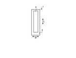
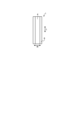
図1Aは、実施形態に係る電気化学セルの一例を示す横断面図であり、図1Bは、実施形態に係る電気化学セルの一例を空気極側からみた側面図であり、図1Cは、実施形態に係る電気化学セルの一例をインターコネクタ側からみた側面図である。なお、図1A~図1Cは、電気化学セルの各構成の一部を拡大して示している。以下、電気化学セルを単にセルという場合もある。
FIG. 1A is a cross-sectional view showing an example of an electrochemical cell according to an embodiment, FIG. 1B is a side view of an example of an electrochemical cell according to an embodiment, viewed from the air electrode side, and FIG. 1C is a cross-sectional view showing an example of an electrochemical cell according to an embodiment. FIG. 3 is a side view of an example of an electrochemical cell according to the embodiment, viewed from the interconnector side. Note that FIGS. 1A to 1C show enlarged portions of each structure of the electrochemical cell. Hereinafter, the electrochemical cell may be simply referred to as a cell.
図1A~図1Cに示す例において、セル1は中空平板型で、細長い板状である。図1Bに示すように、セル1の全体を側面から見た形状は、たとえば、長さ方向Lの辺の長さが5cm~50cmで、この長さ方向Lに直交する幅方向Wの長さが、たとえば1cm~10cmの長方形である。このセル1の全体の厚み方向Tの厚さは、たとえば1mm~5mmである。
In the example shown in FIGS. 1A to 1C, the cell 1 is a hollow flat plate and has an elongated plate shape. As shown in FIG. 1B, the shape of the entire cell 1 when viewed from the side has, for example, a side length in the length direction L of 5 cm to 50 cm, and a length in the width direction W perpendicular to the length direction L. is, for example, a rectangle with a size of 1 cm to 10 cm. The overall thickness of this cell 1 in the thickness direction T is, for example, 1 mm to 5 mm.
図1Aに示すように、セル1は、導電性の支持基板2と、素子部3と、インターコネクタ4とを備えている。支持基板2は、一対の対向する平坦面n1、n2、およびかかる平坦面n1、n2を接続する一対の円弧状の側面mを有する柱状である。
As shown in FIG. 1A, the cell 1 includes a conductive support substrate 2, an element section 3, and an interconnector 4. The support substrate 2 has a columnar shape having a pair of opposing flat surfaces n1 and n2 and a pair of arcuate side surfaces m connecting the flat surfaces n1 and n2.
素子部3は、支持基板2の平坦面n1上に設けられている。かかる素子部3は、燃料極層5と、固体電解質層6と、空気極層8とを有している。また、図1Aに示す例では、セル1の平坦面n2上にインターコネクタ4が位置している。なお、セル1は、固体電解質層6と空気極層8との間に中間層7を備えていてもよい。
The element section 3 is provided on the flat surface n1 of the support substrate 2. The element section 3 includes a fuel electrode layer 5, a solid electrolyte layer 6, and an air electrode layer 8. Further, in the example shown in FIG. 1A, the interconnector 4 is located on the flat surface n2 of the cell 1. Note that the cell 1 may include an intermediate layer 7 between the solid electrolyte layer 6 and the air electrode layer 8.
また、図1Bに示すように、空気極層8はセル1の下端まで延びていない。セル1の下端部では、固体電解質層6のみが平坦面n1の表面に露出している。また、図1Cに示すように、インターコネクタ4がセル1の下端まで延びていてもよい。セル1の下端部では、インターコネクタ4および固体電解質層6が表面に露出している。なお、図1Aに示すように、セル1の一対の円弧状の側面mにおける表面では、固体電解質層6が露出している。インターコネクタ4は、セル1の下端まで延びていなくてもよい。
Furthermore, as shown in FIG. 1B, the air electrode layer 8 does not extend to the lower end of the cell 1. At the lower end of the cell 1, only the solid electrolyte layer 6 is exposed on the surface of the flat surface n1. Further, as shown in FIG. 1C, the interconnector 4 may extend to the lower end of the cell 1. At the lower end of the cell 1, the interconnector 4 and the solid electrolyte layer 6 are exposed to the surface. Note that, as shown in FIG. 1A, the solid electrolyte layer 6 is exposed on the surface of the pair of arcuate side faces m of the cell 1. The interconnector 4 does not have to extend to the lower end of the cell 1.
以下、セル1を構成する各構成部材について説明する。
Hereinafter, each component that makes up the cell 1 will be explained.
支持基板2は、ガスが流れるガス流路2aを内部に有している。図1Aに示す支持基板2の例は、6つのガス流路2aを有している。支持基板2は、ガス透過性を有し、ガス流路2aを流れる燃料ガスを燃料極層5まで透過させる。支持基板2は、導電性を有していてもよい。導電性を有する支持基板2は、素子部3で生じた電気をインターコネクタ4に集電する。
The support substrate 2 has a gas passage 2a inside thereof through which gas flows. The example of the support substrate 2 shown in FIG. 1A has six gas flow paths 2a. The support substrate 2 has gas permeability and allows the fuel gas flowing through the gas flow path 2 a to pass through to the fuel electrode layer 5 . The support substrate 2 may be electrically conductive. The conductive support substrate 2 collects electricity generated in the element section 3 to the interconnector 4 .
支持基板2の材料は、たとえば、鉄族金属成分および無機酸化物を含む。鉄族金属成分は、たとえば、Ni(ニッケル)および/またはNiOであってもよい。無機酸化物は、たとえば、特定の希土類元素酸化物であってもよい。希土類元素酸化物は、たとえば、Sc、Y、La、Nd、Sm、Gd、DyおよびYbから選択される1以上の希土類元素を含んでよい。
The material of the support substrate 2 includes, for example, an iron group metal component and an inorganic oxide. The iron group metal component may be, for example, Ni (nickel) and/or NiO. The inorganic oxide may be, for example, a specific rare earth element oxide. The rare earth element oxide may contain one or more rare earth elements selected from, for example, Sc, Y, La, Nd, Sm, Gd, Dy, and Yb.
燃料極層5の材料には、一般的に公知のものを使用することができる。燃料極層5は、多孔質の導電性セラミックス、たとえば酸化カルシウム、酸化マグネシウム、または希土類元素酸化物が固溶しているZrO2と、Niおよび/またはNiOとを含むセラミックスなどを用いてもよい。この希土類元素酸化物は、たとえば、Sc、Y、La、Nd、Sm、Gd、DyおよびYbから選択される複数の希土類元素を含んでもよい。酸化カルシウム、酸化マグネシウム、または希土類元素酸化物が固溶しているZrO2を安定化ジルコニアと称する場合もある。安定化ジルコニアは、部分安定化ジルコニアを含んでもよい。
Generally known materials can be used for the material of the fuel electrode layer 5. The fuel electrode layer 5 may be made of a porous conductive ceramic, such as a ceramic containing calcium oxide, magnesium oxide, or ZrO 2 in which a rare earth element oxide is dissolved as a solid solution, and Ni and/or NiO. . This rare earth element oxide may include a plurality of rare earth elements selected from, for example, Sc, Y, La, Nd, Sm, Gd, Dy, and Yb. ZrO 2 containing calcium oxide, magnesium oxide, or rare earth element oxide as a solid solution is sometimes referred to as stabilized zirconia. Stabilized zirconia may include partially stabilized zirconia.
固体電解質層6は、電解質であり、燃料極層5と空気極層8との間でイオンの受け渡しをする。同時に、固体電解質層6は、ガス遮断性を有し、燃料ガスと酸素含有ガスとのリークを生じにくくする。
The solid electrolyte layer 6 is an electrolyte and transfers ions between the fuel electrode layer 5 and the air electrode layer 8. At the same time, the solid electrolyte layer 6 has gas barrier properties, making it difficult for fuel gas and oxygen-containing gas to leak.
固体電解質層6の材料は、たとえば、3モル%~15モル%の希土類元素酸化物、酸化カルシウム、酸化マグネシウムが固溶したZrO2であってもよい。希土類元素酸化物は、たとえば、Sc、Y、La、Nd、Sm、Gd、DyおよびYbから選択される1以上の希土類元素を含んでよい。固体電解質層6は、たとえば、La、Nd、Sm、GdまたはYbが固溶したCeO2を含んでもよく、ScまたはYbが固溶したBaZrO3を含んでもよく、ScまたはYbが固溶したBaCeO3を含んでもよい。
The material of the solid electrolyte layer 6 may be, for example, ZrO 2 in which 3 mol % to 15 mol % of rare earth element oxide, calcium oxide, and magnesium oxide are solidly dissolved. The rare earth element oxide may contain one or more rare earth elements selected from, for example, Sc, Y, La, Nd, Sm, Gd, Dy, and Yb. The solid electrolyte layer 6 may include, for example, CeO 2 in which La, Nd, Sm, Gd or Yb is dissolved in solid solution, BaZrO 3 in which Sc or Yb is dissolved in solid solution, BaCeO in which Sc or Yb is dissolved in solid solution. 3 may be included.
空気極層8は、ガス透過性を有している。空気極層8の開気孔率は、たとえば20%~50%、特に30%~50%の範囲であってもよい。
The air electrode layer 8 has gas permeability. The open porosity of the air electrode layer 8 may be in the range of, for example, 20% to 50%, particularly 30% to 50%.
空気極層8の材料は、一般的に空気極に用いられるものであれば特に制限はない。空気極層8の材料は、たとえば、いわゆるABO3型のペロブスカイト型酸化物など導電性セラミックスでもよい。
The material for the air electrode layer 8 is not particularly limited as long as it is commonly used for air electrodes. The material of the air electrode layer 8 may be, for example, a conductive ceramic such as a so-called ABO 3 perovskite oxide.
空気極層8の材料は、たとえば、AサイトにSr(ストロンチウム)とLa(ランタン)が共存する複合酸化物であってもよい。このような複合酸化物の例としては、LaxSr1-xCoyFe1-yO3、LaxSr1-xMnO3、LaxSr1-xFeO3、LaxSr1-xCoO3などが挙げられる。なお、xは0<x<1、yは0<y<1である。
The material of the air electrode layer 8 may be, for example, a composite oxide in which Sr (strontium) and La (lanthanum) coexist at the A site. Examples of such composite oxides include La x Sr 1-x Co y Fe 1-y O 3 , La x Sr 1-x MnO 3 , La x Sr 1-x FeO 3 , La x Sr 1-x Examples include CoO3 . Note that x is 0<x<1, and y is 0<y<1.
また、素子部3が中間層7を有する場合、中間層7は、拡散抑制層としての機能を有する。空気極層8に含まれるSr(ストロンチウム)などの元素が固体電解質層6に拡散すると、かかる固体電解質層6にたとえばSrZrO3などの電気抵抗層が形成される。中間層7は、Srを拡散させにくくすることで、SrZrO3その他の電気絶縁性を有する酸化物が形成されにくくする。
Further, when the element section 3 includes the intermediate layer 7, the intermediate layer 7 has a function as a diffusion suppressing layer. When an element such as Sr (strontium) contained in the air electrode layer 8 diffuses into the solid electrolyte layer 6, an electrical resistance layer such as SrZrO 3 is formed in the solid electrolyte layer 6. The intermediate layer 7 makes it difficult for Sr to diffuse, thereby making it difficult for SrZrO 3 and other electrically insulating oxides to be formed.
中間層7の材料は、一般的に空気極層8と固体電解質層6との間の元素の拡散を生じにくくするものであれば特に制限はない。中間層7の材料は、たとえば、Ce(セリウム)を除く希土類元素が固溶した酸化セリウム(CeO2)を含んでもよい。かかる希土類元素としては、たとえば、Gd(ガドリニウム)、Sm(サマリウム)などを用いてもよい。
The material for the intermediate layer 7 is not particularly limited as long as it generally makes it difficult for elements to diffuse between the air electrode layer 8 and the solid electrolyte layer 6. The material of the intermediate layer 7 may include, for example, cerium oxide (CeO 2 ) in which a rare earth element other than Ce (cerium) is dissolved. As such rare earth elements, for example, Gd (gadolinium), Sm (samarium), etc. may be used.
また、インターコネクタ4は、緻密質であり、支持基板2の内部に位置するガス流路2aを流通する燃料ガス、および支持基板2の外側を流通する酸素含有ガスのリークを生じにくくする。インターコネクタ4は、93%以上、特に95%以上の相対密度を有していてもよい。
Furthermore, the interconnector 4 is dense and prevents leakage of the fuel gas flowing through the gas flow path 2a located inside the support substrate 2 and the oxygen-containing gas flowing outside the support substrate 2. The interconnector 4 may have a relative density of 93% or more, in particular 95% or more.
インターコネクタ4の材料には、ランタンクロマイト系のペロブスカイト型酸化物(LaCrO3系酸化物)、ランタンストロンチウムチタン系のペロブスカイト型酸化物(LaSrTiO3系酸化物)などを用いてもよい。これらの材料は、導電性を有し、かつ水素含有ガスなどの燃料ガスおよび空気などの酸素含有ガスと接触しても還元も酸化もされにくい。また、インターコネクタ4の材料には、金属または合金を用いてもよい。
As the material of the interconnector 4, a lanthanum chromite-based perovskite oxide (LaCrO 3 -based oxide), a lanthanum strontium titanium-based perovskite oxide (LaSrTiO 3 -based oxide), or the like may be used. These materials have electrical conductivity and are not easily reduced or oxidized even when they come into contact with fuel gas such as hydrogen-containing gas and oxygen-containing gas such as air. Furthermore, the interconnector 4 may be made of metal or an alloy.
<電気化学セル装置>
次に、上述したセル1を用いた本実施形態に係る電気化学セル装置について、図2A~図2Cを参照しながら説明する。図2Aは、第1の実施形態に係る電気化学セル装置の一例を示す斜視図であり、図2Bは、図2Aに示すX-X線の断面図であり、図2Cは、第1の実施形態に係る電気化学セル装置の一例を示す上面図である。 <Electrochemical cell device>
Next, an electrochemical cell device according to this embodiment using thecell 1 described above will be described with reference to FIGS. 2A to 2C. FIG. 2A is a perspective view showing an example of the electrochemical cell device according to the first embodiment, FIG. 2B is a cross-sectional view taken along line XX shown in FIG. 2A, and FIG. 2C is a perspective view showing an example of the electrochemical cell device according to the first embodiment. FIG. 2 is a top view showing an example of an electrochemical cell device according to the embodiment.
次に、上述したセル1を用いた本実施形態に係る電気化学セル装置について、図2A~図2Cを参照しながら説明する。図2Aは、第1の実施形態に係る電気化学セル装置の一例を示す斜視図であり、図2Bは、図2Aに示すX-X線の断面図であり、図2Cは、第1の実施形態に係る電気化学セル装置の一例を示す上面図である。 <Electrochemical cell device>
Next, an electrochemical cell device according to this embodiment using the
図2Aに示すように、セルスタック装置10は、セル1の厚み方向T(図1A参照)に配列(積層)された複数のセル1を有するセルスタック11と、固定部材12とを備える。
As shown in FIG. 2A, the cell stack device 10 includes a cell stack 11 having a plurality of cells 1 arranged (stacked) in the thickness direction T of the cells 1 (see FIG. 1A), and a fixing member 12.
固定部材12は、固定材13と、支持部材14とを有する。支持部材14は、セル1を支持する。固定材13は、セル1を支持部材14に固定する。また、支持部材14は、支持体15と、ガスタンク16とを有する。支持部材14である支持体15およびガスタンク16は、たとえば金属製であり導電性を有している。
The fixing member 12 includes a fixing member 13 and a support member 14. The support member 14 supports the cell 1. The fixing member 13 fixes the cell 1 to the support member 14 . Further, the support member 14 includes a support body 15 and a gas tank 16. The support body 15 and the gas tank 16, which are the support members 14, are made of metal and have electrical conductivity, for example.
セルスタック装置10は、セルスタック11を挟んで固定部材12と向かい合うように位置する固定部材12aを備えていてもよい。固定部材12は、セル1の下端側を固定し、固定部材12aは、セル1の上端側を固定する。なお、図2A~図2Cでは、固定部材12aの図示を省略している。
The cell stack device 10 may include a fixing member 12a positioned opposite the fixing member 12 with the cell stack 11 in between. The fixing member 12 fixes the lower end of the cell 1, and the fixing member 12a fixes the upper end of the cell 1. Note that in FIGS. 2A to 2C, illustration of the fixing member 12a is omitted.
図2Bに示すように、支持体15は、複数のセル1の下端部が挿入される挿入孔15aを有している。複数のセル1の下端部と挿入孔15aの内壁とは、固定材13で接合されている。
As shown in FIG. 2B, the support body 15 has an insertion hole 15a into which the lower end portions of the plurality of cells 1 are inserted. The lower ends of the plurality of cells 1 and the inner wall of the insertion hole 15a are joined with a fixing material 13.
ガスタンク16は、挿入孔15aを通じて複数のセル1に反応ガスを供給する開口部と、かかる開口部の周囲に位置する凹溝16aとを有する。支持体15の外周の端部は、ガスタンク16の凹溝16aに充填された接合材21によって、ガスタンク16と接合されている。
The gas tank 16 has an opening for supplying reaction gas to the plurality of cells 1 through the insertion hole 15a, and a groove 16a located around the opening. An end of the outer periphery of the support body 15 is joined to the gas tank 16 by a joining material 21 filled in the groove 16a of the gas tank 16.
図2Aに示す例では、支持部材14である支持体15とガスタンク16とで形成される内部空間22に燃料ガスが貯留される。ガスタンク16にはガス流通管20が接続されている。燃料ガスは、このガス流通管20を通してガスタンク16に供給され、ガスタンク16からセル1の内部のガス流路2a(図1A参照)に供給され、セル1の上端部側から排出される。ガスタンク16に供給される燃料ガスは、後述する改質器102(図7参照)で生成される。セルスタック装置10が固定部材12aを備える場合、セル1の上端部側から固定部材12aに排出された燃料ガスは、さらに図示しないガス排出管から排出、処理されてもよいし、再度改質器を通してセルスタック11、またはセルスタック11とは別のセルスタックに供給されてもよい。
In the example shown in FIG. 2A, fuel gas is stored in the internal space 22 formed by the support body 15, which is the support member 14, and the gas tank 16. A gas flow pipe 20 is connected to the gas tank 16. The fuel gas is supplied to the gas tank 16 through the gas distribution pipe 20, supplied from the gas tank 16 to the gas passage 2a (see FIG. 1A) inside the cell 1, and discharged from the upper end side of the cell 1. The fuel gas supplied to the gas tank 16 is generated in a reformer 102 (see FIG. 7), which will be described later. When the cell stack device 10 includes the fixing member 12a, the fuel gas discharged from the upper end side of the cell 1 to the fixing member 12a may be further discharged and processed from a gas exhaust pipe (not shown), or may be sent to the reformer again. It may be supplied to the cell stack 11 or a cell stack different from the cell stack 11 through the cell stack 11 .
水素リッチな燃料ガスは、原燃料を水蒸気改質などすることによって生成することができる。水蒸気改質により燃料ガスを生成する場合には、燃料ガスは水蒸気を含む。
Hydrogen-rich fuel gas can be produced by steam reforming raw fuel. When fuel gas is generated by steam reforming, the fuel gas contains steam.
図2Aに示す例では、2列のセルスタック11、支持部材14を有している。支持部材14は、2つの支持体15およびガスタンク16を備えている。2列のセルスタック11はそれぞれ、複数のセル1を有する。各セルスタック11は、各支持体15に固定されている。ガスタンク16は上面に2つの貫通孔を有している。各貫通孔には、各支持体15が配置されている。内部空間22は、1つのガスタンク16と、2つの支持体15とで形成される。セルスタック装置10が図示しない固定部材12aを備える場合、支持部材14aが支持部材14のように、2つの支持体およびガスタンクを備えていてもよい。図2Aでは、2列のセルスタック11を有するセルスタック装置10を示したが、セルスタック装置は1列のセルスタック11を有してもよいし、3列以上のセルスタック11を有してもよい。
The example shown in FIG. 2A has two rows of cell stacks 11 and support members 14. The support member 14 includes two supports 15 and a gas tank 16. Each of the two rows of cell stacks 11 has a plurality of cells 1 . Each cell stack 11 is fixed to each support 15. The gas tank 16 has two through holes on its upper surface. Each support body 15 is arranged in each through hole. Internal space 22 is formed by one gas tank 16 and two supports 15. When the cell stack device 10 includes a fixing member 12a (not shown), the support member 14a may include two supports and a gas tank like the support member 14. Although FIG. 2A shows the cell stack device 10 having two rows of cell stacks 11, the cell stack device may have one row of cell stacks 11, or may have three or more rows of cell stacks 11. Good too.
挿入孔15aの形状は、たとえば、上面視で長円形状である。挿入孔15aは、たとえば、セル1の配列方向すなわち厚み方向Tの長さが、セルスタック11の両端に位置する2つの端部集電部材17の間の距離よりも大きい。挿入孔15aの幅は、たとえば、セル1の幅方向W(図1A参照)の長さよりも大きい。
The shape of the insertion hole 15a is, for example, an oval shape when viewed from above. For example, the length of the insertion hole 15a in the arrangement direction of the cells 1, that is, the thickness direction T, is larger than the distance between the two end current collecting members 17 located at both ends of the cell stack 11. The width of the insertion hole 15a is, for example, larger than the length of the cell 1 in the width direction W (see FIG. 1A).
図2Bに示すように、挿入孔15aの内壁とセル1の下端部との接合部は、固定材13が充填され、固化されている。これにより、挿入孔15aの内壁と複数個のセル1の下端部とがそれぞれ接合・固定され、また、セル1の下端部同士が接合・固定されている。各セル1のガス流路2aは、下端部で支持部材14の内部空間22と連通している。
As shown in FIG. 2B, the joint between the inner wall of the insertion hole 15a and the lower end of the cell 1 is filled with the fixing material 13 and solidified. Thereby, the inner wall of the insertion hole 15a and the lower end portions of the plurality of cells 1 are respectively joined and fixed, and the lower end portions of the cells 1 are joined and fixed to each other. The gas flow path 2a of each cell 1 communicates with the internal space 22 of the support member 14 at its lower end.
固定材13および接合材21は、ガラスなどの導電性が低いものを用いることができる。固定材13および接合材21の具体的な材料としては、非晶質ガラスなどを用いてもよく、特に結晶化ガラスなどを用いてもよい。
For the fixing material 13 and the bonding material 21, materials with low conductivity such as glass can be used. As specific materials for the fixing material 13 and the bonding material 21, amorphous glass or the like may be used, and in particular, crystallized glass or the like may be used.
結晶化ガラスとしては、たとえば、SiO2-CaO系、MgO-B2O3系、La2O3-B2O3-MgO系、La2O3-B2O3-ZnO系、SiO2-CaO-ZnO系などの材料のいずれかを用いてもよく、特にSiO2-MgO系の材料を用いてもよい。
Examples of crystallized glass include SiO 2 -CaO system, MgO-B 2 O 3 system, La 2 O 3 -B 2 O 3 -MgO system, La 2 O 3 -B 2 O 3 -ZnO system, SiO 2 -CaO--ZnO-based materials may be used, and in particular, SiO 2 -MgO-based materials may be used.
また、図2Bに示すように、複数のセル1のうち隣接するセル1の間には、導電部材18が介在している。導電部材18は、隣接する一方のセル1の燃料極層5と他方のセル1の空気極層8とを電気的に直列に接続する。より具体的には、導電部材18は、隣接する一方のセル1の燃料極層5と電気的に接続されたインターコネクタ4と、他方のセル1の空気極層8とを接続している。インターコネクタ4が金属または合金である場合、インターコネクタ4と導電部材18とが一体化していてもよいし、導電部材18がインターコネクタ4を兼ねてもよい。なお、導電部材18の詳細については後述する。
Furthermore, as shown in FIG. 2B, a conductive member 18 is interposed between adjacent cells 1 among the plurality of cells 1. The conductive member 18 electrically connects the fuel electrode layer 5 of one adjacent cell 1 and the air electrode layer 8 of the other cell 1 in series. More specifically, the conductive member 18 connects the interconnector 4, which is electrically connected to the fuel electrode layer 5 of one adjacent cell 1, and the air electrode layer 8 of the other cell 1. When the interconnector 4 is made of metal or an alloy, the interconnector 4 and the conductive member 18 may be integrated, or the conductive member 18 may also serve as the interconnector 4. Note that details of the conductive member 18 will be described later.
また、図2Bに示すように、複数のセル1の配列方向における最も外側に位置するセル1に、端部集電部材17が電気的に接続されている。端部集電部材17は、セルスタック11の外側に突出する導電部19に接続されている。導電部19は、セル1の発電により生じた電気を集電して外部に引き出す。なお、図2Aでは、端部集電部材17の図示を省略している。
Further, as shown in FIG. 2B, the end current collecting member 17 is electrically connected to the outermost cell 1 in the arrangement direction of the plurality of cells 1. The end current collecting member 17 is connected to a conductive portion 19 protruding to the outside of the cell stack 11 . The conductive part 19 collects electricity generated by the power generation of the cell 1 and draws it to the outside. Note that in FIG. 2A, illustration of the end current collecting member 17 is omitted.
また、図2Cに示すように、セルスタック装置10は、2つのセルスタック11A、11Bが直列に接続され、一つの電池として機能する。そのため、セルスタック装置10の導電部19は、正極端子19Aと、負極端子19Bと、接続端子19Cとに区別される。
Further, as shown in FIG. 2C, in the cell stack device 10, two cell stacks 11A and 11B are connected in series, and function as one battery. Therefore, the conductive portion 19 of the cell stack device 10 is divided into a positive terminal 19A, a negative terminal 19B, and a connection terminal 19C.
正極端子19Aは、セルスタック11が発電した電力を外部に出力する場合の正極であり、セルスタック11Aにおける正極側の端部集電部材17に電気的に接続される。負極端子19Bは、セルスタック11が発電した電力を外部に出力する場合の負極であり、セルスタック11Bにおける負極側の端部集電部材17に電気的に接続される。
The positive electrode terminal 19A is a positive electrode for outputting the electric power generated by the cell stack 11 to the outside, and is electrically connected to the end current collecting member 17 on the positive electrode side of the cell stack 11A. The negative electrode terminal 19B is a negative electrode for outputting the electric power generated by the cell stack 11 to the outside, and is electrically connected to the end current collecting member 17 on the negative electrode side of the cell stack 11B.
接続端子19Cは、セルスタック11Aにおける負極側の端部集電部材17と、セルスタック11Bにおける正極側の端部集電部材17とを電気的に接続する。
The connection terminal 19C electrically connects the negative end current collecting member 17 of the cell stack 11A and the positive end current collecting member 17 of the cell stack 11B.
<導電部材>
つづいて、第1の実施形態に係る電気化学セル装置が有する導電部材18の詳細について、図3を参照しながらさらに説明する。図3は、第1の実施形態に係る電気化学セル装置を拡大した断面図である。図3に示すセルスタック装置10は、図2Bに示すセルスタック装置10が有するセルスタック11を拡大視したものに相当する。なお、図3では、たとえばセル1、導電部材18などを単純化して図示している。また、後述する他の図面でも、構成要素を単純化して図示する場合がある。 <Conductive member>
Next, details of theconductive member 18 included in the electrochemical cell device according to the first embodiment will be further described with reference to FIG. 3. FIG. 3 is an enlarged cross-sectional view of the electrochemical cell device according to the first embodiment. The cell stack device 10 shown in FIG. 3 corresponds to an enlarged view of the cell stack 11 included in the cell stack device 10 shown in FIG. 2B. In addition, in FIG. 3, for example, the cell 1, the conductive member 18, etc. are shown in a simplified manner. Further, in other drawings to be described later, constituent elements may be illustrated in a simplified manner.
つづいて、第1の実施形態に係る電気化学セル装置が有する導電部材18の詳細について、図3を参照しながらさらに説明する。図3は、第1の実施形態に係る電気化学セル装置を拡大した断面図である。図3に示すセルスタック装置10は、図2Bに示すセルスタック装置10が有するセルスタック11を拡大視したものに相当する。なお、図3では、たとえばセル1、導電部材18などを単純化して図示している。また、後述する他の図面でも、構成要素を単純化して図示する場合がある。 <Conductive member>
Next, details of the
図3に示すように、厚み方向Tに隣り合うセル1の間には、長さ方向に延びる導電部材18が位置している。セル1は、ガスが流れるガス流路2aを有している。ガス流路2aは、供給口2a1と排出口2a2とを有する。供給口2a1には、内部空間22内に貯留された燃料ガスが供給される。排出口2a2は、セル1の内部から燃料ガスを排出する。
As shown in FIG. 3, a conductive member 18 extending in the length direction is located between adjacent cells 1 in the thickness direction T. The cell 1 has a gas flow path 2a through which gas flows. The gas flow path 2a has a supply port two a1 and a discharge port two a2. The fuel gas stored in the internal space 22 is supplied to the supply port two a1. The exhaust port 2a2 exhausts fuel gas from inside the cell 1.
かかるセルスタック装置10は、発電時の温度にばらつきが生じる場合がある。具体的には、セル1のうち、排出口2a2側に近いセル1の部分1aの方が、供給口2a1側に近いセル1の部分1b側よりも温度が上昇する。このため、セル1の部分1aでは、たとえば、発電に適した温度よりも高温となり、耐久性が低下しやすくなる。
In such a cell stack device 10, variations in temperature may occur during power generation. Specifically, the temperature of the portion 1a of the cell 1 closer to the discharge port 2a2 side increases than that of the portion 1b of the cell 1 closer to the supply port 2a1 side. Therefore, in the portion 1a of the cell 1, for example, the temperature becomes higher than the temperature suitable for power generation, and the durability tends to decrease.
そこで、本実施形態では、厚み方向Tに隣り合うセル1間に、電気抵抗率が異なる第1部位181と第2部位182とを有する導電部材18を適用することで温度のばらつきを低減させる。具体的には、第1部位181が部分1aに接続され、第2部位182が部分1bに接続されるように導電部材18を位置させる。第1部位181の電気抵抗率は、第2部位182の電気抵抗率よりも大きい。以下、電気抵抗率を単に抵抗率といい、電気抵抗を単に抵抗という場合もある。
Therefore, in this embodiment, temperature variations are reduced by applying a conductive member 18 having a first portion 181 and a second portion 182 having different electrical resistivities between cells 1 adjacent in the thickness direction T. Specifically, the conductive member 18 is positioned such that the first portion 181 is connected to the portion 1a and the second portion 182 is connected to the portion 1b. The electrical resistivity of the first portion 181 is greater than the electrical resistivity of the second portion 182. Hereinafter, electrical resistivity may be simply referred to as resistivity, and electrical resistance may simply be referred to as resistance.
これにより、第1部位181では、第2部位182よりも通電量が低減し、第1部位181における抵抗加熱が抑えられる。その結果、第1部位181およびそれに接続されたセル1の部分1aでの温度上昇が、第2部位およびそれに接続されたセル1の部分1bよりも低減される。このため、本実施形態によれば、導電部材18およびセルスタック装置10の耐久性が高くなる。
As a result, the amount of current applied to the first portion 181 is lower than that of the second portion 182, and resistance heating in the first portion 181 is suppressed. As a result, the temperature rise in the first portion 181 and the portion 1a of the cell 1 connected thereto is lower than that in the second portion 181 and the portion 1b of the cell 1 connected thereto. Therefore, according to this embodiment, the durability of the conductive member 18 and the cell stack device 10 is increased.
例えば、第1部位181が導電部材18の排出口側の端部であり、第2部位182が導電部材18の供給口側の端部であってもよい。また、導電部材18の排出口側の端部から供給口側の端部までの長さlに対し、導電部材18の排出口側の端部からl/3離れた部位が第1部位181であり、導電部材18の供給口側の端部からl/3離れた部位が第2部位182であってもよい。
For example, the first portion 181 may be the end of the conductive member 18 on the discharge port side, and the second portion 182 may be the end of the conductive member 18 on the supply port side. Furthermore, with respect to the length l from the end of the conductive member 18 on the discharge port side to the end of the supply port, the first portion 181 is located 1/3 away from the end of the conductive member 18 on the discharge port side. Alternatively, the second portion 182 may be a portion 1/3 away from the end of the conductive member 18 on the supply port side.
セル1Aとセル1Bの間に位置する第1部位181の電気抵抗は、セル1Aとセル1Bの間に位置する第2部位182の電気抵抗よりも、たとえば0.05Ω以上大きくてもよい。第1部位181の電気抵抗と第2部位182の電気抵抗の差が0.05Ω以上であることで、第1部位181の通電量が小さくなり第1部位181における抵抗加熱が小さくなり、導電部材18およびセルスタック装置10の耐久性が高くなる。
The electrical resistance of the first portion 181 located between the cells 1A and 1B may be greater than the electrical resistance of the second portion 182 located between the cells 1A and 1B by, for example, 0.05Ω or more. Since the difference between the electrical resistance of the first portion 181 and the electrical resistance of the second portion 182 is 0.05Ω or more, the amount of current applied to the first portion 181 is reduced, resistance heating in the first portion 181 is reduced, and the conductive member 18 and the durability of the cell stack device 10 are increased.
導電部材18の排出口側に位置する半分を第1部位181とし、供給口側に位置する半分を第2部位182としてもよい。また、導電部材18の排出口側の端部から供給口側の端部までの長さlに対し、導電部材18の排出口側の端部からl/3までの部位を第1部位181とし、導電部材18の供給口側の端部からl/3までの部位を第2部位182としてもよい。第1部位181の抵抗率は、第2部位182の抵抗率よりも、0.8Ω・m以上大きくてもよい。第1部位181の抵抗率が、第2部位182の抵抗率より0.8Ω・m以上大きいと、第1部位181の通電量が有意に低減される。なお、抵抗率は各部位において例えば任意の3点以上を測定した平均値としてもよい。
The half of the conductive member 18 located on the discharge port side may be the first portion 181, and the half located on the supply port side may be the second portion 182. In addition, with respect to the length l from the end of the conductive member 18 on the discharge port side to the end of the supply port, a portion from the end of the conductive member 18 on the discharge port side to 1/3 is defined as the first portion 181. , the second portion 182 may be a portion up to ⅓ from the end of the conductive member 18 on the supply port side. The resistivity of the first portion 181 may be greater than the resistivity of the second portion 182 by 0.8 Ω·m or more. When the resistivity of the first portion 181 is greater than the resistivity of the second portion 182 by 0.8 Ω·m or more, the amount of current flowing through the first portion 181 is significantly reduced. Note that the resistivity may be an average value obtained by measuring, for example, three or more points at each location.
ここで、導電部材18の具体的な構成の一例につき、図4および図5を用いて説明する。図4は、第1の実施形態に係る電気化学セル装置が有する導電部材の一例を示す横断面図である。
Here, an example of a specific configuration of the conductive member 18 will be explained using FIGS. 4 and 5. FIG. 4 is a cross-sectional view showing an example of a conductive member included in the electrochemical cell device according to the first embodiment.
図4に示すように、導電部材18は、隣接するセル1のうち、一方のセル1であるセル1Aに接続される接続部18aと、他方のセル1であるセル1Bに接続される接続部18bとを有する。また、導電部材18は、幅方向Wの両端に連結部18cを有しており、接続部18a,18bを接続する。これにより、導電部材18は、厚み方向Tに隣り合うセル1同士を電気的に接続することができる。
As shown in FIG. 4, the conductive member 18 has a connecting portion 18a connected to one cell 1, ie, cell 1A, among adjacent cells 1, and a connecting portion 18a, connected to the other cell 1, ie, cell 1B. 18b. Further, the conductive member 18 has connecting portions 18c at both ends in the width direction W, and connects the connecting portions 18a and 18b. Thereby, the conductive member 18 can electrically connect cells 1 adjacent to each other in the thickness direction T.
また、接続部18a,18bは、セル1A,1Bと接触する接触部18a1,18b1と、セル1A,1Bとは非接触の非接触部18a2,18b2とを有している。
Furthermore, the connecting portions 18a, 18b have contact portions 18a1, 18b1 that contact the cells 1A, 1B, and non-contact portions 18a2, 18b2 that do not contact the cells 1A, 1B.
図5は、図4に示すA-A線に沿った断面図である。導電部材18は、セル1の長さ方向Lに延在している。導電部材18は、断面視で櫛歯状を有しており、接続部18a,18bは、連結部18cからセル1A,1Bに向かって互い違いに伸びている。
FIG. 5 is a cross-sectional view taken along line AA shown in FIG. 4. The conductive member 18 extends in the length direction L of the cell 1. The conductive member 18 has a comb-like shape when viewed in cross section, and the connecting portions 18a and 18b extend alternately from the connecting portion 18c toward the cells 1A and 1B.
次に、第1部位181および第2部位182を有する導電部材18の具体例につき、図6A~図6Dを用いて説明する。図6Aは、第1の実施形態に係る電気化学セル装置が有する導電部材の一例を示す断面図である。
Next, a specific example of the conductive member 18 having the first portion 181 and the second portion 182 will be described using FIGS. 6A to 6D. FIG. 6A is a cross-sectional view showing an example of a conductive member included in the electrochemical cell device according to the first embodiment.
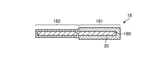
図6Aに示すように、導電部材18は、基材180と、基材180を覆う被膜30とを有してもよい。基材180は、導電性および耐熱性を有する。基材180は、クロムを含有する。基材180は、たとえば、ステンレス鋼である。基材180は、たとえば、金属酸化物を含有してもよい。
As shown in FIG. 6A, the conductive member 18 may include a base material 180 and a coating 30 that covers the base material 180. The base material 180 has electrical conductivity and heat resistance. Base material 180 contains chromium. Base material 180 is, for example, stainless steel. The base material 180 may contain, for example, a metal oxide.
被膜30は、電気絶縁性または低い導電性を有している。被膜30は、たとえば、酸化クロム(Cr2O3)、酸化アルミニウム(Al2O3)、Alおよび/またはSiを含む複合酸化物などを含有する。図6Aに示す導電部材18は、被膜30の厚みを異ならせることにより、抵抗率が異なる第1部位181および第2部位182を有している。すなわち、第2部位182と比較して被膜30の厚みが大きい第1部位181の抵抗率は、第2部位182の抵抗率よりも大きくなる。
The coating 30 has electrical insulation or low conductivity. The coating 30 contains, for example, chromium oxide (Cr 2 O 3 ), aluminum oxide (Al 2 O 3 ), a composite oxide containing Al and/or Si, and the like. The conductive member 18 shown in FIG. 6A has a first portion 181 and a second portion 182 having different resistivities by making the thickness of the coating 30 different. That is, the resistivity of the first portion 181, where the coating 30 is thicker than the second portion 182, is greater than the resistivity of the second portion 182.
図6B~図6Dは、第1の実施形態に係る電気化学セル装置が有する導電部材の別の一例を示す断面図である。
6B to 6D are cross-sectional views showing another example of a conductive member included in the electrochemical cell device according to the first embodiment.
図6Bに示すように、導電部材18は、基材180と、基材180を覆う被膜31を有してもよい。
As shown in FIG. 6B, the conductive member 18 may have a base material 180 and a coating 31 that covers the base material 180.
被膜31は、導電性を有している。被膜31は、たとえば、導電性を有する金属材料および/または金属酸化物を含有する。図6Bに示すように、導電部材18は、被膜31の厚みを異ならせることにより、抵抗率が異なる第1部位181および第2部位182を有していてもよい。すなわち、第1部位181と比較して被膜31の厚みが大きい第2部位182の抵抗率は、第1部位181の抵抗率よりも小さくなる。被膜31に含まれる導電性を有する金属酸化物は、たとえばスピネル構造を有する複合酸化物、たとえば、ZnMnCoO4などのZn(CoxMn1-x)2O4(0<x<1)、Mn1.5Co1.5O4、MnCo2O4、CoMn2O4、などであってもよい。導電性を有する金属酸化物は、いわゆるABO3型のペロブスカイト型酸化物であってもよい。
The coating 31 has electrical conductivity. The coating 31 contains, for example, a conductive metal material and/or a metal oxide. As shown in FIG. 6B, the conductive member 18 may have a first portion 181 and a second portion 182 having different resistivities by making the thickness of the coating 31 different. That is, the resistivity of the second portion 182, where the coating 31 is thicker than the first portion 181, is smaller than the resistivity of the first portion 181. The conductive metal oxide contained in the film 31 is , for example, a complex oxide having a spinel structure, such as Zn( CoxMn1 -x ) 2O4 (0<x<1) such as ZnMnCoO4 , Mn 1.5 Co 1.5 O 4 , MnCo 2 O 4 , CoMn 2 O 4 , etc. may be used. The electrically conductive metal oxide may be a so-called ABO 3 perovskite oxide.
なお、導電部材18は、被膜30および被膜30よりも高い導電性を有する被膜31の両方を有していてもよい。導電部材18は、たとえば、基材180上を覆う被膜30と、さらに被膜30上を覆う被膜31を有していてもよい。このとき、第2部位182は、第1部位181と比較して、被膜30の厚みが小さくてもよい。また、第2部位182は、第1部位181と比較して、被膜31の厚みが大きくてもよい。
Note that the conductive member 18 may include both the coating 30 and the coating 31 having higher conductivity than the coating 30. The conductive member 18 may have, for example, a coating 30 that covers the base material 180 and a coating 31 that further covers the coating 30. At this time, the thickness of the coating 30 in the second portion 182 may be smaller than that in the first portion 181. Further, the thickness of the coating 31 in the second portion 182 may be greater than that in the first portion 181.
また、図6Cに示すように、導電部材18は、基材180と、基材180を覆う被膜32,33を有してもよい。
Further, as shown in FIG. 6C, the conductive member 18 may have a base material 180 and coatings 32 and 33 that cover the base material 180.
被膜32,33は、導電性または絶縁性を有している。被膜32は、被膜33よりも絶縁性が高くてもよい。また、被膜33は、被膜32よりも導電性が高くてもよい。
The coatings 32 and 33 have conductivity or insulation. Coating 32 may have higher insulating properties than coating 33. Further, the coating 33 may have higher conductivity than the coating 32.
図6Cに示すように、導電部材18は、被膜32,33の材料を異ならせることにより、抵抗率が異なる第1部位181および第2部位182を有していてもよい。すなわち、被膜32と比較して絶縁性が低いまたは導電性が高い被膜33を有する第2部位182の抵抗率は、第1部位181の抵抗率よりも小さくなる。
As shown in FIG. 6C, the conductive member 18 may have a first portion 181 and a second portion 182 having different resistivities by using different materials for the coatings 32 and 33. That is, the resistivity of the second portion 182 having the coating 33 having lower insulation or higher conductivity than the coating 32 is smaller than the resistivity of the first portion 181.
被膜32,33は、気孔率が異なる同じ材料であってもよい。被膜32の気孔率が被膜33の気孔率より大きいと、被膜32は、被膜33と比較して絶縁性が高くなる。被膜32の気孔率が被膜33の気孔率より大きいと、被膜32は、被膜33と比較して導電性が低くなる。被膜32,33の材料は、被膜30,31に含まれるような材料であってもよい。
The coatings 32 and 33 may be made of the same material with different porosity. If the porosity of the coating 32 is greater than the porosity of the coating 33, the coating 32 will have higher insulating properties than the coating 33. If the porosity of coating 32 is greater than the porosity of coating 33, coating 32 will have lower conductivity than coating 33. The material of the coatings 32 and 33 may be the same material as that contained in the coatings 30 and 31.
図6Dに示すように、導電部材18は、基材180の材料が互いに異なる部位180a,180bを有していてもよい。部位180bは、部位180aと比較して導電性が高い。これにより、第2部位182の抵抗率は、第1部位181の抵抗率よりも小さくなる。
As shown in FIG. 6D, the conductive member 18 may have portions 180a and 180b where the base material 180 is made of different materials. Portion 180b has higher conductivity than portion 180a. As a result, the resistivity of the second portion 182 becomes smaller than the resistivity of the first portion 181.
このように、本実施形態に係る電気化学セル装置が有する導電部材18は、いかなる方法により作製されたものであってもよい。なお、図6A、図6Bに示す被膜30,31は、たとえば、ディップ法において塗布回数および/またはディップ液の濃度を変更させて形成してもよく、電着またはめっき法において成膜電極を変更させて形成してもよい。また、図6Cに示す被膜32,33は、たとえば、ディップ法においてディップ液の種類を変更させて形成してもよい。また、図6Dに示す導電部材18は、たとえば、溶接または接合により形成してもよい。
In this way, the conductive member 18 included in the electrochemical cell device according to this embodiment may be manufactured by any method. The films 30 and 31 shown in FIGS. 6A and 6B may be formed, for example, by changing the number of coatings and/or the concentration of the dip liquid in a dip method, or by changing the film forming electrode in an electrodeposition or plating method. It may also be formed by Further, the coatings 32 and 33 shown in FIG. 6C may be formed, for example, by changing the type of dipping liquid in a dipping method. Further, the conductive member 18 shown in FIG. 6D may be formed by, for example, welding or joining.
<モジュール>
次に、上述したセルスタック装置10を用いた本実施形態に係るモジュール100について、図7を用いて説明する。図7は、第1の実施形態に係るモジュールを示す外観斜視図である。図7では、収納容器101の一部である前面および後面を取り外し、内部に収納される燃料電池のセルスタック装置10を後方に取り出した状態を示している。 <Module>
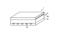
Next, amodule 100 according to this embodiment using the above-described cell stack device 10 will be described using FIG. 7. FIG. 7 is an external perspective view showing the module according to the first embodiment. FIG. 7 shows a state in which the front and rear surfaces, which are part of the storage container 101, are removed and the fuel cell cell stack device 10 housed inside is taken out rearward.
次に、上述したセルスタック装置10を用いた本実施形態に係るモジュール100について、図7を用いて説明する。図7は、第1の実施形態に係るモジュールを示す外観斜視図である。図7では、収納容器101の一部である前面および後面を取り外し、内部に収納される燃料電池のセルスタック装置10を後方に取り出した状態を示している。 <Module>
Next, a
図7に示すように、モジュール100は、収納容器101、および収納容器101内に収納されたセルスタック装置10を備えている。また、セルスタック装置10の上方には、改質器102が配置されている。
As shown in FIG. 7, the module 100 includes a storage container 101 and a cell stack device 10 housed within the storage container 101. Further, above the cell stack device 10, a reformer 102 is arranged.
かかる改質器102は、天然ガス、灯油などの原燃料を改質して燃料ガスを生成し、セル1に供給する。原燃料は、原燃料供給管103を通じて改質器102に供給される。改質器102は、水を気化させる気化部102aと、改質部102bとを備えていてもよい。改質部102bは、図示しない改質触媒を備えており、原燃料を燃料ガスに改質する。このような改質器102は、効率の高い改質反応である水蒸気改質を行うことができる。
The reformer 102 generates fuel gas by reforming raw fuel such as natural gas or kerosene, and supplies the fuel gas to the cell 1. Raw fuel is supplied to the reformer 102 through a raw fuel supply pipe 103. The reformer 102 may include a vaporizing section 102a that vaporizes water, and a reforming section 102b. The reforming section 102b includes a reforming catalyst (not shown), and reformes the raw fuel into fuel gas. Such a reformer 102 can perform steam reforming, which is a highly efficient reforming reaction.
そして、改質器102で生成された燃料ガスは、ガス流通管20、固定部材12を通じて、セル1のガス流路2a(図1A参照)に供給される。
Then, the fuel gas generated in the reformer 102 is supplied to the gas flow path 2a of the cell 1 (see FIG. 1A) through the gas distribution pipe 20 and the fixing member 12.
また、上述の構成のモジュール100では、ガスの燃焼、セル1の発電等に伴い、通常発電時におけるモジュール100内の温度が500℃~1000℃程度となる。
Furthermore, in the module 100 configured as described above, the temperature inside the module 100 during normal power generation is about 500° C. to 1000° C. due to combustion of gas, power generation of the cell 1, etc.
このようなモジュール100においては、上述したように、耐久性が高いセルスタック装置10を備えていることにより、耐久性が高いモジュール100とすることができる。
In such a module 100, as described above, by including the cell stack device 10 with high durability, the module 100 can have high durability.
<モジュール収容装置>
図8は、第1の実施形態に係るモジュール収容装置の一例を示す分解斜視図である。モジュール収容装置110は、外装ケース111と、図7で示したモジュール100と、図示しない補機と、を備えている。補器は、モジュール100の運転を行う。モジュール100および補器は、外装ケース111内に収容されている。なお、図8においては一部構成を省略して示している。 <Module housing device>
FIG. 8 is an exploded perspective view showing an example of the module housing device according to the first embodiment. Themodule housing device 110 includes an exterior case 111, the module 100 shown in FIG. 7, and auxiliary equipment not shown. The auxiliary equipment operates the module 100. The module 100 and auxiliary equipment are housed in an exterior case 111. Note that in FIG. 8, some configurations are omitted.
図8は、第1の実施形態に係るモジュール収容装置の一例を示す分解斜視図である。モジュール収容装置110は、外装ケース111と、図7で示したモジュール100と、図示しない補機と、を備えている。補器は、モジュール100の運転を行う。モジュール100および補器は、外装ケース111内に収容されている。なお、図8においては一部構成を省略して示している。 <Module housing device>
FIG. 8 is an exploded perspective view showing an example of the module housing device according to the first embodiment. The
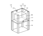
図8に示すモジュール収容装置110の外装ケース111は、支柱112と外装板113とを有する。仕切板114は、外装ケース111内を上下に区画している。外装ケース111内の仕切板114より上側の空間は、モジュール100を収容するモジュール収容室115であり、外装ケース111内の仕切板114より下側の空間は、モジュール100を運転する補機を収容する補機収容室116である。なお、図8では、補機収容室116に収容する補機を省略して示している。
The exterior case 111 of the module housing device 110 shown in FIG. 8 includes a support 112 and an exterior plate 113. The partition plate 114 divides the interior of the exterior case 111 into upper and lower sections. The space above the partition plate 114 in the exterior case 111 is a module storage chamber 115 that accommodates the module 100, and the space below the partition plate 114 in the exterior case 111 accommodates auxiliary equipment that operates the module 100. This is the auxiliary equipment storage chamber 116. Note that, in FIG. 8, the auxiliary equipment accommodated in the auxiliary equipment storage chamber 116 is omitted.
また、仕切板114は、補機収容室116の空気をモジュール収容室115側に流すための空気流通口117を有している。モジュール収容室115を構成する外装板113は、モジュール収容室115内の空気を排気するための排気口118を有している。
Furthermore, the partition plate 114 has an air flow port 117 for flowing air from the auxiliary equipment storage chamber 116 to the module storage chamber 115 side. The exterior plate 113 configuring the module storage chamber 115 has an exhaust port 118 for exhausting the air inside the module storage chamber 115 .
このようなモジュール収容装置110においては、上述したように、耐久性が高いモジュール100をモジュール収容室115に備えていることにより、耐久性が高いモジュール収容装置110とすることができる。
In such a module accommodating device 110, by providing the highly durable modules 100 in the module accommodating chamber 115 as described above, the module accommodating device 110 can have high durability.
[第2の実施形態]
図9は、第2の実施形態に係る電気化学セル装置を拡大した断面図である。図9に示すセルスタック装置10は、導電部材18として抵抗率の異なる第1導電部材18Aと第2導電部材18Bとを有する点で、上記した第1の実施形態に係るセルスタック装置10が有する導電部材18と相違する。第2導電部材18Bの抵抗率は、第1導電部材18Aの抵抗率よりも小さく、第1導電部材18Aおよび第2導電部材18Bは、隣り合うセル1間にそれぞれ配置される。このように、導電部材18として抵抗率の異なる第1導電部材18Aおよび第2導電部材18Bを使用した場合であっても、第1導電部材18Aおよびセル1の部分1aでの温度上昇が低減される。このため、本実施形態に係る電気化学セル装置によれば、導電部材18およびセルスタック装置10の耐久性が高くなる。 [Second embodiment]
FIG. 9 is an enlarged cross-sectional view of the electrochemical cell device according to the second embodiment. Thecell stack device 10 shown in FIG. 9 has a first conductive member 18A and a second conductive member 18B having different resistivities as the conductive members 18, which is different from the cell stack device 10 according to the first embodiment described above. This is different from the conductive member 18. The resistivity of the second conductive member 18B is smaller than the resistivity of the first conductive member 18A, and the first conductive member 18A and the second conductive member 18B are respectively arranged between adjacent cells 1. In this way, even when the first conductive member 18A and the second conductive member 18B having different resistivities are used as the conductive member 18, the temperature rise in the first conductive member 18A and the portion 1a of the cell 1 is reduced. Ru. Therefore, according to the electrochemical cell device according to this embodiment, the durability of the conductive member 18 and the cell stack device 10 is increased.
図9は、第2の実施形態に係る電気化学セル装置を拡大した断面図である。図9に示すセルスタック装置10は、導電部材18として抵抗率の異なる第1導電部材18Aと第2導電部材18Bとを有する点で、上記した第1の実施形態に係るセルスタック装置10が有する導電部材18と相違する。第2導電部材18Bの抵抗率は、第1導電部材18Aの抵抗率よりも小さく、第1導電部材18Aおよび第2導電部材18Bは、隣り合うセル1間にそれぞれ配置される。このように、導電部材18として抵抗率の異なる第1導電部材18Aおよび第2導電部材18Bを使用した場合であっても、第1導電部材18Aおよびセル1の部分1aでの温度上昇が低減される。このため、本実施形態に係る電気化学セル装置によれば、導電部材18およびセルスタック装置10の耐久性が高くなる。 [Second embodiment]
FIG. 9 is an enlarged cross-sectional view of the electrochemical cell device according to the second embodiment. The
第1導電部材18Aおよび第2導電部材18Bは、たとえば、図6A~図6Dに示す第1部位181および第2部位182に準じてそれぞれ作製することができる。また、第1導電部材18Aおよび第2導電部材18Bは、互いに接触させてもよく、離間させてもよい。第1導電部材18Aおよび第2導電部材18Bを離間させると、第1導電部材18Aを流れる電流をより低下させることができることから、導電部材18およびセルスタック装置10の耐久性が高くなる。
The first conductive member 18A and the second conductive member 18B can be manufactured, for example, in accordance with the first portion 181 and the second portion 182 shown in FIGS. 6A to 6D, respectively. Further, the first conductive member 18A and the second conductive member 18B may be in contact with each other or may be separated from each other. When the first conductive member 18A and the second conductive member 18B are spaced apart, the current flowing through the first conductive member 18A can be further reduced, which increases the durability of the conductive member 18 and the cell stack device 10.
[第3の実施形態]
図10は、第3の実施形態に係る電気化学セル装置の一例を示す上面図である。図10に示すセルスタック装置10は、厚み方向T(第1方向)に並ぶセル1を複数備えるセルスタック11を有する。セルスタック11は、セル1の幅方向W(第2方向)に隣り合うセルスタック11A(第1セルスタック)およびセルスタック11B(第2セルスタック)を有する。 [Third embodiment]
FIG. 10 is a top view showing an example of an electrochemical cell device according to the third embodiment. Thecell stack device 10 shown in FIG. 10 has a cell stack 11 including a plurality of cells 1 arranged in the thickness direction T (first direction). The cell stack 11 includes a cell stack 11A (first cell stack) and a cell stack 11B (second cell stack) that are adjacent to each other in the width direction W (second direction) of the cell 1.
図10は、第3の実施形態に係る電気化学セル装置の一例を示す上面図である。図10に示すセルスタック装置10は、厚み方向T(第1方向)に並ぶセル1を複数備えるセルスタック11を有する。セルスタック11は、セル1の幅方向W(第2方向)に隣り合うセルスタック11A(第1セルスタック)およびセルスタック11B(第2セルスタック)を有する。 [Third embodiment]
FIG. 10 is a top view showing an example of an electrochemical cell device according to the third embodiment. The
このように、セルスタック11A,11Bを有するセルスタック装置10では、発電時に発生した熱がセルスタック11A,11Bの間にこもり、セルスタック装置10内の温度にばらつきが生じる場合がある。具体的には、セルスタック11Aのうち、セルスタック11Bに近い部分11Aaの方が、セルスタック11Bから離れた部分11Ab側よりも温度が上昇する。このため、部分11Aaでは、たとえば、発電に適した温度よりも高温となり、耐久性が低下しやすくなる。
As described above, in the cell stack device 10 having the cell stacks 11A and 11B, heat generated during power generation may be trapped between the cell stacks 11A and 11B, causing variations in temperature within the cell stack device 10. Specifically, the temperature of the portion 11Aa of the cell stack 11A that is closer to the cell stack 11B is higher than that of the portion 11Ab that is farther from the cell stack 11B. Therefore, in the portion 11Aa, for example, the temperature becomes higher than the temperature suitable for power generation, and the durability tends to decrease.
そこで、図10に示すように、セルスタック11Aが有するセル1間に、セルスタック11Bからの距離に応じて抵抗率が異なる第1部位181と第2部位182とを有する導電部材18を適用することで温度のばらつきを低減させてもよい。具体的には、第1部位181が部分11Aaに位置するセル1に接続され、第2部位182が部分11Abに位置するセル1に接続されるように導電部材18を位置させる。第1部位181の抵抗率は、第2部位182の抵抗率よりも大きい。
Therefore, as shown in FIG. 10, a conductive member 18 having a first portion 181 and a second portion 182 having different resistivities depending on the distance from the cell stack 11B is applied between the cells 1 included in the cell stack 11A. This may reduce temperature variations. Specifically, the conductive member 18 is positioned such that the first portion 181 is connected to the cell 1 located in the portion 11Aa, and the second portion 182 is connected to the cell 1 located in the portion 11Ab. The resistivity of the first portion 181 is greater than the resistivity of the second portion 182.
これにより、第1部位181に接続されたセル1を有する部分11Aaでは、第2部位182に接続されたセル1を有する部分11Abよりも通電量が低減し、第1導電部材18Aおよび部分11Aaでの温度上昇が低減される。このため、本実施形態に係る電気化学セル装置によれば、導電部材18およびセルスタック装置10の耐久性が高くなる。
As a result, the amount of current is reduced in the portion 11Aa having the cell 1 connected to the first portion 181 than in the portion 11Ab having the cell 1 connected to the second portion 182, and in the first conductive member 18A and the portion 11Aa. temperature rise is reduced. Therefore, according to the electrochemical cell device according to this embodiment, the durability of the conductive member 18 and the cell stack device 10 is increased.
[第4の実施形態]
図11は、第4の実施形態に係る電気化学セル装置が有する電気化学セルの一例を示す斜視図である。図11に示すセル1は、素子部3Bと、素子部3Bを挟む導電部材91,92とを有する平板型の電気化学セルである。素子部3Bは、固体電解質層(たとえば、固体電解質層6)と、固体電解質層を挟む第1電極層(たとえば、燃料極層5)および第2電極層(たとえば、空気極層8)を有する。導電部材91,92は、反応ガスが流れる流路97,98をそれぞれ有しており、不図示のシール部材等で封止されている。 [Fourth embodiment]
FIG. 11 is a perspective view showing an example of an electrochemical cell included in the electrochemical cell device according to the fourth embodiment. Thecell 1 shown in FIG. 11 is a flat electrochemical cell having an element part 3B and conductive members 91 and 92 sandwiching the element part 3B. The element section 3B includes a solid electrolyte layer (for example, solid electrolyte layer 6), a first electrode layer (for example, fuel electrode layer 5) and a second electrode layer (for example, air electrode layer 8) that sandwich the solid electrolyte layer. . The conductive members 91 and 92 have channels 97 and 98, respectively, through which the reaction gas flows, and are sealed with a seal member (not shown) or the like.
図11は、第4の実施形態に係る電気化学セル装置が有する電気化学セルの一例を示す斜視図である。図11に示すセル1は、素子部3Bと、素子部3Bを挟む導電部材91,92とを有する平板型の電気化学セルである。素子部3Bは、固体電解質層(たとえば、固体電解質層6)と、固体電解質層を挟む第1電極層(たとえば、燃料極層5)および第2電極層(たとえば、空気極層8)を有する。導電部材91,92は、反応ガスが流れる流路97,98をそれぞれ有しており、不図示のシール部材等で封止されている。 [Fourth embodiment]
FIG. 11 is a perspective view showing an example of an electrochemical cell included in the electrochemical cell device according to the fourth embodiment. The
図12は、平板型の電気化学セルにおける温度分布の一例を示す平面図である。図12に示すように、素子部3Bの周囲には、導電部材91,92に接するセパレータ40が位置している。また、導電部材91または導電部材92と向かい合う素子部3Bの表面3aは、セル1の発電時には素子部3Bの中心P1に近い部分が高温となり、中心P1から離れた外縁側に向かって同心円状に温度が低下する。
FIG. 12 is a plan view showing an example of temperature distribution in a flat plate electrochemical cell. As shown in FIG. 12, a separator 40 in contact with conductive members 91 and 92 is located around the element portion 3B. In addition, the surface 3a of the element part 3B facing the conductive member 91 or 92 has a high temperature at the part near the center P1 of the element part 3B when the cell 1 is generating electricity, and the surface 3a is concentrically shaped toward the outer edge away from the center P1. Temperature decreases.
図13は、第4の実施形態に係る電気化学セル装置が有する導電部材の一例を示す縦断面図である。複数のセル1を積層させたセルスタック装置10Bでは、互いに隣り合う一方のセル1の導電部材91と他のセル1の導電部材92とが、導電部材であるインターコネクタ93を介して電気的に接続されている。以下、素子部3B間に位置する導電部材91,92およびインターコネクタ93をまとめて導電部材18と称する場合がある。
FIG. 13 is a longitudinal cross-sectional view showing an example of a conductive member included in the electrochemical cell device according to the fourth embodiment. In a cell stack device 10B in which a plurality of cells 1 are stacked, a conductive member 91 of one cell 1 adjacent to each other and a conductive member 92 of another cell 1 are electrically connected via an interconnector 93 which is a conductive member. It is connected. Hereinafter, the conductive members 91 and 92 and the interconnector 93 located between the element portions 3B may be collectively referred to as the conductive member 18.
上述したように、発電時に高温となった素子部3Bの中心P1の付近では、温度が低下しにくいことから、セルスタック装置10内の温度にばらつきが生じる場合がある。具体的には、セル1のうち、素子部3Bの中心P1に近い部分は、素子部3Bの中心P1から離れた外縁側よりも温度が上昇し、たとえば、発電に適した温度よりも高温となり、耐久性が低下しやすくなる。
As described above, the temperature in the vicinity of the center P1 of the element portion 3B, which is at a high temperature during power generation, is difficult to decrease, so that the temperature within the cell stack device 10 may vary. Specifically, the temperature of the portion of the cell 1 that is closer to the center P1 of the element portion 3B increases than the outer edge side that is farther from the center P1 of the element portion 3B, and for example, becomes higher than the temperature suitable for power generation. , durability tends to decrease.
そこで、図13に示すように、セルスタック装置10Bが有する素子部3B間に、中心P1からの距離に応じて抵抗率が異なる第1部位181と第2部位182とを有する導電部材18を適用することで温度のばらつきを低減させてもよい。具体的には、第1部位181が中心P1に近い素子部3Bの第1電極層に接続され、第2部位182が中心P1から離れた素子部3Bの第1電極層に接続されるように導電部材18を位置させる。第1部位181の抵抗率は、第2部位182の抵抗率よりも大きい。
Therefore, as shown in FIG. 13, a conductive member 18 having a first portion 181 and a second portion 182 having different resistivities depending on the distance from the center P1 is applied between the element portions 3B of the cell stack device 10B. By doing so, variations in temperature may be reduced. Specifically, the first portion 181 is connected to the first electrode layer of the element portion 3B near the center P1, and the second portion 182 is connected to the first electrode layer of the element portion 3B distant from the center P1. The conductive member 18 is positioned. The resistivity of the first portion 181 is greater than the resistivity of the second portion 182.
これにより、第1部位181に接続された素子部3Bを有する部分では、第2部位182に接続された素子部3Bを有する部分よりも通電量が低減し、第1部位181およびそれに接続された部分での温度上昇が低減される。このため、本実施形態に係る電気化学セル装置によれば、導電部材18およびセルスタック装置10Bの耐久性が高くなる。
As a result, the amount of current is reduced in the part having the element part 3B connected to the first part 181 than in the part having the element part 3B connected to the second part 182, and The temperature rise in the area is reduced. Therefore, according to the electrochemical cell device according to this embodiment, the durability of the conductive member 18 and the cell stack device 10B is increased.
なお、上記では、導電部材91,92およびインターコネクタ93をまとめて導電部材18として説明したが、導電部材91,92とは異なるインターコネクタ93を第3導電部材として適用し、導電部材91,92を並列に接続してもよい。
In addition, although the conductive members 91, 92 and the interconnector 93 were collectively described as the conductive member 18 in the above, the interconnector 93, which is different from the conductive members 91, 92, is applied as a third conductive member, and the conductive members 91, 92 may be connected in parallel.
[第5の実施形態]
図14は、第5の実施形態に係る電気化学セル装置が有する導電部材の一例を示す縦断面図である。図14に示すように、セルスタック装置10Cは、導電部材18として抵抗率の異なる第1導電部材18Aと第2導電部材18Bとを有してもよい。第2導電部材18Bの抵抗率は、第1導電部材18Aの抵抗率よりも小さく、第1導電部材18Aおよび第2導電部材18Bは、隣り合うセル1間にそれぞれ配置される。このように、導電部材18として抵抗率の異なる第1導電部材18Aおよび第2導電部材18Bを使用した場合であっても、第1導電部材18Aおよびそれに接続されたセル1の部分での温度上昇が低減される。このため、本実施形態に係る電気化学セル装置によれば、導電部材18およびセルスタック装置10Cの耐久性が高くなる。 [Fifth embodiment]
FIG. 14 is a longitudinal cross-sectional view showing an example of a conductive member included in the electrochemical cell device according to the fifth embodiment. As shown in FIG. 14, thecell stack device 10C may include a first conductive member 18A and a second conductive member 18B having different resistivities as the conductive members 18. The resistivity of the second conductive member 18B is smaller than the resistivity of the first conductive member 18A, and the first conductive member 18A and the second conductive member 18B are respectively arranged between adjacent cells 1. In this way, even if the first conductive member 18A and the second conductive member 18B having different resistivities are used as the conductive member 18, the temperature will rise in the first conductive member 18A and the portion of the cell 1 connected thereto. is reduced. Therefore, according to the electrochemical cell device according to this embodiment, the durability of the conductive member 18 and the cell stack device 10C is increased.
図14は、第5の実施形態に係る電気化学セル装置が有する導電部材の一例を示す縦断面図である。図14に示すように、セルスタック装置10Cは、導電部材18として抵抗率の異なる第1導電部材18Aと第2導電部材18Bとを有してもよい。第2導電部材18Bの抵抗率は、第1導電部材18Aの抵抗率よりも小さく、第1導電部材18Aおよび第2導電部材18Bは、隣り合うセル1間にそれぞれ配置される。このように、導電部材18として抵抗率の異なる第1導電部材18Aおよび第2導電部材18Bを使用した場合であっても、第1導電部材18Aおよびそれに接続されたセル1の部分での温度上昇が低減される。このため、本実施形態に係る電気化学セル装置によれば、導電部材18およびセルスタック装置10Cの耐久性が高くなる。 [Fifth embodiment]
FIG. 14 is a longitudinal cross-sectional view showing an example of a conductive member included in the electrochemical cell device according to the fifth embodiment. As shown in FIG. 14, the
[第6の実施形態]
図15Aは、第6の実施形態に係る電気化学セル装置が有する電気化学セルの一例を示す横断面図である。図15B、図15Cは、第6の実施形態に係る電気化学セル装置が有する電気化学セルの他の一例を示す横断面図である。 [Sixth embodiment]
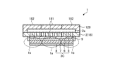
FIG. 15A is a cross-sectional view showing an example of an electrochemical cell included in the electrochemical cell device according to the sixth embodiment. 15B and 15C are cross-sectional views showing other examples of electrochemical cells included in the electrochemical cell device according to the sixth embodiment.
図15Aは、第6の実施形態に係る電気化学セル装置が有する電気化学セルの一例を示す横断面図である。図15B、図15Cは、第6の実施形態に係る電気化学セル装置が有する電気化学セルの他の一例を示す横断面図である。 [Sixth embodiment]
FIG. 15A is a cross-sectional view showing an example of an electrochemical cell included in the electrochemical cell device according to the sixth embodiment. 15B and 15C are cross-sectional views showing other examples of electrochemical cells included in the electrochemical cell device according to the sixth embodiment.
図15A~図15Cに示すように、セル1は、燃料極層5、固体電解質層6、中間層7および空気極層8が積層された素子部3Cと、支持基板2とを有している。支持基板2は、素子部3Cの燃料極層5と接する部位に貫通孔または細孔を有するとともに、ガス流路2aの外側に位置する部材120を有する。支持基板2は、ガス流路2aと素子部3Cとの間でガスを流通させることができる。支持基板2は、例えば、1または複数の金属板を含んでもよい。金属板の材料は、クロムを含有していてもよい。金属板は、導電性の被覆層を有していてもよい。支持基板2は、隣接するセル1同士を電気的に接続する導電部材である。素子部3Cは、支持基板2上に直接形成されていてもよいし、接合材により支持基板2に接合されていてもよい。
As shown in FIGS. 15A to 15C, the cell 1 includes an element section 3C in which a fuel electrode layer 5, a solid electrolyte layer 6, an intermediate layer 7, and an air electrode layer 8 are laminated, and a support substrate 2. . The support substrate 2 has a through hole or pore at a portion of the element portion 3C that contacts the fuel electrode layer 5, and also has a member 120 located outside the gas flow path 2a. The support substrate 2 can allow gas to flow between the gas flow path 2a and the element section 3C. Support substrate 2 may include, for example, one or more metal plates. The material of the metal plate may contain chromium. The metal plate may have a conductive coating layer. The support substrate 2 is a conductive member that electrically connects adjacent cells 1 to each other. The element portion 3C may be directly formed on the support substrate 2, or may be bonded to the support substrate 2 with a bonding material.
図15Aに示す例では、燃料極層5の側面は固体電解質層6により被覆され、燃料ガスが流れるガス流路2aを気密に封止している。図15Bに示すように、燃料極層5の側面はガラスまたはセラミックを含む緻密な封止材9で被覆され、封止されていてもよい。燃料極層5の側面を被覆する封止材9は、電気絶縁性を有していてもよい。
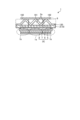
In the example shown in FIG. 15A, the side surface of the fuel electrode layer 5 is covered with a solid electrolyte layer 6, and the gas flow path 2a through which the fuel gas flows is hermetically sealed. As shown in FIG. 15B, the side surface of the fuel electrode layer 5 may be covered and sealed with a dense sealing material 9 containing glass or ceramic. The sealing material 9 covering the side surface of the fuel electrode layer 5 may have electrical insulation properties.
また、支持基板2のガス流路2aは、図15Cに示すように凹凸を有する部材120により形成されていてもよい。
Further, the gas flow path 2a of the support substrate 2 may be formed of a member 120 having unevenness as shown in FIG. 15C.
第6の実施形態において、部材120は、隣接する別のセル1の空気極層8と、セル間接続部材などの他の導電部材および接合材を介して接合されている。なお、部材120は、他の導電部材等を介さずに直接別のセル1の空気極層8と接触していてもよい。
In the sixth embodiment, the member 120 is joined to the air electrode layer 8 of another adjacent cell 1 via another conductive member such as an inter-cell connecting member and a bonding material. Note that the member 120 may be in direct contact with the air electrode layer 8 of another cell 1 without using another conductive member or the like.
第6の実施形態においても、支持基板2(導電部材18)は、抵抗率が異なる第1部位181および第2部位182を有している。支持基板2(導電部材18)は、第1~第4の実施形態に係る電気化学セル装置のように、第1部位181を高温となるセル1の部分1aに位置させ、第2部位182を比較的低温となるセル1の部分1bに位置させてもよい。第1部位181の抵抗率が、第2部位182の抵抗率よりも大きいことにより、第1部位181に接続されたセル1の部分1aでは、第2部位182に接続された部分1bよりも通電量が低減し、、第1部位181および部分1aでの温度上昇が低減される。このため、本実施形態に係る電気化学セル装置によれば、支持基板2(導電部材18)およびセルスタック装置10の耐久性が高くなる。なお、図15A~図15Cでは、高温となるセル1の部分1aとして、第2の実施形態のように素子部3Cの中心に近い部分を示したが、たとえば、第1の実施形態のように燃料ガスの排出口側に近い部分が、高温となるセル1の部分1aとなってもよい。
In the sixth embodiment as well, the support substrate 2 (conductive member 18) has a first portion 181 and a second portion 182 having different resistivities. As in the electrochemical cell devices according to the first to fourth embodiments, the support substrate 2 (conductive member 18) has a first portion 181 located in the high temperature portion 1a of the cell 1, and a second portion 182 located in the high temperature portion 1a of the cell 1. It may be located in the portion 1b of the cell 1 where the temperature is relatively low. Since the resistivity of the first portion 181 is greater than the resistivity of the second portion 182, the portion 1a of the cell 1 connected to the first portion 181 is more energized than the portion 1b connected to the second portion 182. The temperature increase in the first portion 181 and the portion 1a is reduced. Therefore, according to the electrochemical cell device according to the present embodiment, the durability of the support substrate 2 (conductive member 18) and the cell stack device 10 is increased. Note that in FIGS. 15A to 15C, the portion 1a of the cell 1 that becomes high temperature is shown as a portion near the center of the element portion 3C as in the second embodiment, but for example, as in the first embodiment, A portion close to the fuel gas outlet side may be the portion 1a of the cell 1 that becomes high temperature.
<実験例1>
図5に示すセルスタック装置10(セルスタック11)を作製した。セル1のサイズは、170mm(長さ方向L)×27mm(幅方向W)×2.3mm(厚み方向T)の中空平板状とした。導電部材18の形状は、図4、図5に示す櫛歯状であって、第1部位181と第2部位182とは同じ形状とした。具体的には、導電部材18は、セル1と接続部18a,18bとの接触面積が21mm×0.8mm×60片であり、うち、第1部位181が30片、第2部位182が30片となるように作製した。導電部材18は、図6Aに示すものを使用した。また、セルスタック11が有するセル1の数は32枚とし、セルスタック11の中央部に位置するセル1において温度差を評価した。なお、セル1の温度は、導電部材18の長さ方向Lの長さlを基準として、排出口側の端部から概ねl/3離れた位置を第1部位181とし、供給口側の端部から概ねl/3離れた位置を第2部位182として、第1部位181および第2部位182に対応するセル1の各部分にそれぞれ熱電対を配置して測定した。 <Experiment example 1>
A cell stack device 10 (cell stack 11) shown in FIG. 5 was manufactured. The size of thecell 1 was a hollow flat plate of 170 mm (length direction L) x 27 mm (width direction W) x 2.3 mm (thickness direction T). The shape of the conductive member 18 was a comb shape shown in FIGS. 4 and 5, and the first portion 181 and the second portion 182 had the same shape. Specifically, the conductive member 18 has a contact area between the cell 1 and the connecting parts 18a and 18b of 21 mm x 0.8 mm x 60 pieces, of which the first portion 181 has 30 pieces and the second portion 182 has 30 pieces. It was made in pieces. The conductive member 18 shown in FIG. 6A was used. Further, the number of cells 1 included in the cell stack 11 was set to 32, and the temperature difference in the cell 1 located at the center of the cell stack 11 was evaluated. Note that the temperature of the cell 1 is determined based on the length l in the length direction L of the conductive member 18, with the first portion 181 being a position approximately 1/3 away from the end on the discharge port side, and the end on the supply port side being the first portion 181. A position approximately 1/3 away from the second part 182 was defined as the second part 182, and thermocouples were placed in each part of the cell 1 corresponding to the first part 181 and the second part 182, respectively.
図5に示すセルスタック装置10(セルスタック11)を作製した。セル1のサイズは、170mm(長さ方向L)×27mm(幅方向W)×2.3mm(厚み方向T)の中空平板状とした。導電部材18の形状は、図4、図5に示す櫛歯状であって、第1部位181と第2部位182とは同じ形状とした。具体的には、導電部材18は、セル1と接続部18a,18bとの接触面積が21mm×0.8mm×60片であり、うち、第1部位181が30片、第2部位182が30片となるように作製した。導電部材18は、図6Aに示すものを使用した。また、セルスタック11が有するセル1の数は32枚とし、セルスタック11の中央部に位置するセル1において温度差を評価した。なお、セル1の温度は、導電部材18の長さ方向Lの長さlを基準として、排出口側の端部から概ねl/3離れた位置を第1部位181とし、供給口側の端部から概ねl/3離れた位置を第2部位182として、第1部位181および第2部位182に対応するセル1の各部分にそれぞれ熱電対を配置して測定した。 <Experiment example 1>
A cell stack device 10 (cell stack 11) shown in FIG. 5 was manufactured. The size of the
<実験例2>
図5に示すセルスタック装置10に代えて、図9に示すセルスタック装置10を用いたことを除き、実験例1と同様に作製したセルスタック11の中央部に位置するセル1において温度差を評価した。 <Experiment example 2>
The temperature difference in thecell 1 located at the center of the cell stack 11 was fabricated in the same manner as in Experimental Example 1 except that the cell stack device 10 shown in FIG. 9 was used instead of the cell stack device 10 shown in FIG. evaluated.
図5に示すセルスタック装置10に代えて、図9に示すセルスタック装置10を用いたことを除き、実験例1と同様に作製したセルスタック11の中央部に位置するセル1において温度差を評価した。 <Experiment example 2>
The temperature difference in the
<実験例3>
図5に示すセルスタック装置10に代えて、抵抗率が一様の導電部材18を用いたことを除き、実験例1と同様に作製したセルスタック11の中央部に位置するセル1において温度差を評価した。 <Experiment example 3>
Temperature difference in thecell 1 located in the center of the cell stack 11 produced in the same manner as in Experimental Example 1 except that a conductive member 18 having a uniform resistivity was used in place of the cell stack device 10 shown in FIG. was evaluated.
図5に示すセルスタック装置10に代えて、抵抗率が一様の導電部材18を用いたことを除き、実験例1と同様に作製したセルスタック11の中央部に位置するセル1において温度差を評価した。 <Experiment example 3>
Temperature difference in the
<実験例4>
図13に示すセルスタック装置10Bを作製した。セル1のサイズは、200mm×200mm×3.2mmとした。導電部材18の形状は、第1部位181(140mm×140mm)と第2部位182(第1部位181を除く残りの部分)の接触面積を同じにした。また、セルスタック装置10Bが有するセル1の数は20枚とし、セルスタック装置10Bの中央部に位置するセル1において温度差を評価した。なお、セル1の温度は、中心P1から30mm離れた部分と、中心Pから80mm離れた部分にそれぞれ熱電対を配置して測定した。 <Experiment example 4>
Acell stack device 10B shown in FIG. 13 was manufactured. The size of cell 1 was 200 mm x 200 mm x 3.2 mm. The shape of the conductive member 18 was such that the first portion 181 (140 mm x 140 mm) and the second portion 182 (the remaining portion excluding the first portion 181) had the same contact area. Further, the number of cells 1 included in the cell stack device 10B was set to 20, and the temperature difference was evaluated in the cell 1 located at the center of the cell stack device 10B. Note that the temperature of the cell 1 was measured by placing thermocouples at a portion 30 mm away from the center P1 and a portion 80 mm away from the center P, respectively.
図13に示すセルスタック装置10Bを作製した。セル1のサイズは、200mm×200mm×3.2mmとした。導電部材18の形状は、第1部位181(140mm×140mm)と第2部位182(第1部位181を除く残りの部分)の接触面積を同じにした。また、セルスタック装置10Bが有するセル1の数は20枚とし、セルスタック装置10Bの中央部に位置するセル1において温度差を評価した。なお、セル1の温度は、中心P1から30mm離れた部分と、中心Pから80mm離れた部分にそれぞれ熱電対を配置して測定した。 <Experiment example 4>
A
<実験例5>
図13に示すセルスタック装置10Bに代えて、図14に示すセルスタック装置10Cを、実験例4と同様に作製し、セルスタック装置10Cの中央部に位置するセル1において温度差を評価した。 <Experiment example 5>
In place of thecell stack device 10B shown in FIG. 13, a cell stack device 10C shown in FIG. 14 was manufactured in the same manner as in Experimental Example 4, and the temperature difference was evaluated in the cell 1 located in the center of the cell stack device 10C.
図13に示すセルスタック装置10Bに代えて、図14に示すセルスタック装置10Cを、実験例4と同様に作製し、セルスタック装置10Cの中央部に位置するセル1において温度差を評価した。 <Experiment example 5>
In place of the
<実験例6>
図13に示すセルスタック装置10Bに代えて、抵抗率が一様の導電部材18を用いたことを除き、実験例4と同様に作製したセルスタック装置の中央部に位置するセル1において温度差を評価した。 <Experiment example 6>
Temperature difference incell 1 located in the center of a cell stack device manufactured in the same manner as in Experimental Example 4 except that a conductive member 18 having a uniform resistivity was used in place of the cell stack device 10B shown in FIG. was evaluated.
図13に示すセルスタック装置10Bに代えて、抵抗率が一様の導電部材18を用いたことを除き、実験例4と同様に作製したセルスタック装置の中央部に位置するセル1において温度差を評価した。 <Experiment example 6>
Temperature difference in
図16は、電気化学セル装置の耐久性を比較する図である。セル内に供給される燃料ガスの温度を950℃、900℃、850℃の各試験温度とした場合の加速試験を行い、初期値からの電圧降下量が10%に到達するまでの時間をそれぞれ計測した。具体的には、各試験温度に設定した各セルスタック装置の電流密度を0.4A/cm2に調整し、100hr時間ごとに各セルスタック装置の温度を試験温度から750℃に低下させて電圧測定を行った。電圧測定後、各セルスタック装置を再度試験温度に設定して加速試験を継続した。各試験温度において、測定した電圧が初期値に対し10%低い値に低下するまでの時間から加速係数を算出し、750℃で連続運転したとき、電圧が初期値に対し10%低い値に低下するまでの時間(耐久時間)を推定した。図16では、実験例3および実験例6を基準とする耐久時間の相対値を算出し、耐久性を評価した。
FIG. 16 is a diagram comparing the durability of electrochemical cell devices. An accelerated test was performed when the temperature of the fuel gas supplied into the cell was set to 950°C, 900°C, and 850°C, and the time required for the voltage drop to reach 10% from the initial value was determined for each test temperature. I measured it. Specifically, the current density of each cell stack device set at each test temperature was adjusted to 0.4 A/cm 2 , and the temperature of each cell stack device was lowered from the test temperature to 750°C every 100 hr to adjust the voltage. Measurements were taken. After measuring the voltage, each cell stack device was set to the test temperature again and the accelerated test was continued. At each test temperature, the acceleration coefficient is calculated from the time it takes for the measured voltage to drop to a value 10% lower than the initial value, and when the voltage is continuously operated at 750°C, the voltage drops to a value 10% lower than the initial value. We estimated the time it would take to do so (durability time). In FIG. 16, relative values of durability time based on Experimental Example 3 and Experimental Example 6 were calculated to evaluate durability.
図16に示すように、実験例1,2ではいずれも、実験例3と比較して耐久性が向上した。実験例4,5ではいずれも、実験例6と比較して耐久性が向上した。このように各実施形態に係る導電部材18によれば、耐久性が向上し、導電部材18を使用したセルスタックについても、耐久性が向上した。
As shown in FIG. 16, both Experimental Examples 1 and 2 had improved durability compared to Experimental Example 3. In both Experimental Examples 4 and 5, the durability was improved compared to Experimental Example 6. As described above, the conductive member 18 according to each embodiment has improved durability, and the cell stack using the conductive member 18 also has improved durability.
[その他の実施形態]
上述の各実施形態では、「電池化学セル」、「電池化学セル装置」、「モジュール」および「モジュール収容装置」の一例として燃料電池セル、燃料電池セルスタック装置、燃料電池モジュールおよび燃料電池装置を示したが、他の例としてはそれぞれ、電解セル、電解セルスタック装置、電解モジュールおよび電解装置であってもよい。電解セルは、第1電極層および第2電極層を有し、電力の供給により水蒸気を水素と酸素に分解する、または二酸化炭素を一酸化炭素と酸素に分解する。このような電解セル、電解セルスタック装置、電解モジュールおよび電解装置によれば、耐久性が高くなる。 [Other embodiments]
In each of the embodiments described above, a fuel cell, a fuel cell stack device, a fuel cell module, and a fuel cell device are used as examples of a “battery chemical cell,” a “battery chemical cell device,” a “module,” and a “module housing device.” Although shown, other examples may be an electrolytic cell, an electrolytic cell stack device, an electrolytic module, and an electrolytic device, respectively. The electrolytic cell has a first electrode layer and a second electrode layer, and decomposes water vapor into hydrogen and oxygen or decomposes carbon dioxide into carbon monoxide and oxygen by supplying electric power. According to such an electrolytic cell, an electrolytic cell stack device, an electrolytic module, and an electrolytic device, durability becomes high.
以上、本開示について詳細に説明したが、本開示は上述の実施の形態に限定されるものではなく、本開示の要旨を逸脱しない範囲内において、種々の変更、改良等が可能である。
Although the present disclosure has been described in detail above, the present disclosure is not limited to the above-described embodiments, and various changes and improvements can be made without departing from the gist of the present disclosure.
以上のように、実施形態に係る導電部材18は、第1部位181と、第1部位181とは抵抗率が異なる第2部位182とを有する。これにより、耐久性が高い導電部材18が提供可能となる。
As described above, the conductive member 18 according to the embodiment includes the first portion 181 and the second portion 182 having a different resistivity from the first portion 181. This makes it possible to provide the conductive member 18 with high durability.
また、本開示の電気化学セル装置(たとえば、セルスタック装置10)は、上記に記載の導電部材18と、導電部材18に接続された電気化学セル(たとえば、セル1)とを備える。電気化学セルは、第1部位181に接続された第1部分(たとえば、部分1a)と、第2部位182に接続された第2部分(たとえば、部分1b)とを有する。第1部分の温度は、第2部分の温度よりも高く、第1部位181の抵抗率は、第2部位182の抵抗率よりも大きい。これにより、耐久性が高い電気化学セル装置が提供可能となる。
Further, the electrochemical cell device (eg, cell stack device 10) of the present disclosure includes the electrically conductive member 18 described above and an electrochemical cell (eg, cell 1) connected to the electrically conductive member 18. The electrochemical cell has a first portion (eg, portion 1a) connected to a first portion 181 and a second portion (eg, portion 1b) connected to a second portion 182. The temperature of the first portion is higher than the temperature of the second portion, and the resistivity of the first portion 181 is greater than the resistivity of the second portion 182. This makes it possible to provide an electrochemical cell device with high durability.
また、本開示の電気化学セル装置(たとえば、セルスタック装置10C)は、固体電解質層と、電気化学セル(たとえば、セル1)と、第1導電部材18Aと、第2導電部材18Bとを備える。第2導電部材18Bは、第1導電部材18Aと離間している。第1導電部材18Aの抵抗率は、第2導電部材18Bの抵抗率と異なる。これにより、耐久性が高い電気化学セル装置が提供可能となる。
Further, the electrochemical cell device (for example, cell stack device 10C) of the present disclosure includes a solid electrolyte layer, an electrochemical cell (for example, cell 1), a first conductive member 18A, and a second conductive member 18B. . The second conductive member 18B is spaced apart from the first conductive member 18A. The resistivity of the first conductive member 18A is different from the resistivity of the second conductive member 18B. This makes it possible to provide an electrochemical cell device with high durability.
また、本開示のモジュール100は、上記に記載の電気化学セル装置と、電気化学セル装置を収納する収納容器101とを備える。これにより、耐久性が高いモジュール100とすることができる。
Furthermore, the module 100 of the present disclosure includes the electrochemical cell device described above and a storage container 101 that houses the electrochemical cell device. This allows the module 100 to have high durability.
また、本開示のモジュール収容装置110は、上記に記載のモジュール100と、モジュール100の運転を行うための補機と、モジュール100および補機を収容する外装ケース111とを備える。これにより、耐久性が高いモジュール収容装置110とすることができる。
Further, the module housing device 110 of the present disclosure includes the module 100 described above, an auxiliary machine for operating the module 100, and an exterior case 111 that houses the module 100 and the auxiliary machine. This allows the module housing device 110 to have high durability.
今回開示された実施形態は全ての点で例示であって制限的なものではないと考えられるべきである。実に、上記した実施形態は多様な形態で具現され得る。また、上記の実施形態は、添付の請求の範囲及びその趣旨を逸脱することなく、様々な形態で省略、置換、変更されてもよい。
The embodiments disclosed this time should be considered to be illustrative in all respects and not restrictive. Indeed, the embodiments described above may be implemented in various forms. Moreover, the above-described embodiments may be omitted, replaced, or modified in various forms without departing from the scope and spirit of the appended claims.
1 セル
10 セルスタック装置
11 セルスタック
12 固定部材
13 固定材
14 支持部材
15 支持体
16 ガスタンク
17 端部集電部材
18 導電部材
100 モジュール
110 モジュール収容装置
181 第1部位
182 第2部位 1Cell 10 Cell stack device 11 Cell stack 12 Fixing member 13 Fixing material 14 Support member 15 Support body 16 Gas tank 17 End collector member 18 Conductive member 100 Module 110 Module housing device 181 First part 182 Second part
10 セルスタック装置
11 セルスタック
12 固定部材
13 固定材
14 支持部材
15 支持体
16 ガスタンク
17 端部集電部材
18 導電部材
100 モジュール
110 モジュール収容装置
181 第1部位
182 第2部位 1
Claims (9)
- 第1部位と、前記第1部位とは抵抗率が異なる第2部位とを有する
導電部材。 A conductive member having a first portion and a second portion having a different resistivity from the first portion. - 請求項1に記載の導電部材と、
前記導電部材に接続された電気化学セルと
を備え、
前記電気化学セルは、前記第1部位に接続された第1部分と、前記第2部位に接続された第2部分とを有し、
前記第1部分の温度は、前記第2部分の温度よりも高く、
前記第1部位の抵抗率は、前記第2部位の抵抗率よりも大きい
電気化学セル装置。 The conductive member according to claim 1;
an electrochemical cell connected to the conductive member;
The electrochemical cell has a first part connected to the first part and a second part connected to the second part,
The temperature of the first part is higher than the temperature of the second part,
The resistivity of the first portion is greater than the resistivity of the second portion. The electrochemical cell device. - 請求項1に記載の導電部材と、
前記導電部材に接続された電気化学セルと
を備え、
前記電気化学セルは、反応ガスが供給される供給口と前記反応ガスが排出される排出口とを有し、
前記第1部位は、前記電気化学セルの前記排出口側の近くに位置する部分に接続され、
前記第2部位は、前記電気化学セルの前記供給口の近くに位置する部分に接続され、
前記第1部位の抵抗率は、前記第2部位の抵抗率よりも大きい
電気化学セル装置。 The conductive member according to claim 1;
an electrochemical cell connected to the conductive member;
The electrochemical cell has a supply port through which a reaction gas is supplied and an exhaust port through which the reaction gas is discharged,
the first portion is connected to a portion of the electrochemical cell located near the outlet side;
the second section is connected to a portion of the electrochemical cell located near the supply port;
The resistivity of the first portion is greater than the resistivity of the second portion. The electrochemical cell device. - 第1方向に並ぶ複数の電気化学セルと、該複数の電気化学セルを電気的に接続する請求項1に記載の導電部材とを備えるセルスタックを有し、
前記セルスタックは、前記第1方向に交差する第2方向に隣り合う第1セルスタックおよび第2セルスタックを有し、
前記第1セルスタックにおいて、前記第1部位は、前記電気化学セルの前記第2セルスタックの近くに位置する部分に接続され、
前記第2部位は、前記電気化学セルの前記第2セルスタックの近くに位置する部分に接続され、
前記第1部位の抵抗率は、前記第2部位の抵抗率よりも大きい
電気化学セル装置。 A cell stack comprising a plurality of electrochemical cells arranged in a first direction and a conductive member according to claim 1 that electrically connects the plurality of electrochemical cells,
The cell stack includes a first cell stack and a second cell stack that are adjacent to each other in a second direction intersecting the first direction,
in the first cell stack, the first section is connected to a portion of the electrochemical cell located near the second cell stack;
the second portion is connected to a portion of the electrochemical cell located near the second cell stack;
The resistivity of the first portion is greater than the resistivity of the second portion. The electrochemical cell device. - 請求項1に記載の導電部材と、
前記導電部材に接続された電気化学セルと
を備え、
前記電気化学セルは、前記導電部材と向かい合う素子部を有し、
前記第1部位は、前記素子部の中心部の近くに接続され、
前記第2部位は、前記素子部の中心部から離れた外縁の近くに接続され、
前記第1部位の抵抗率は、前記第2部位の抵抗率よりも大きい
電気化学セル装置。 The conductive member according to claim 1;
an electrochemical cell connected to the conductive member;
The electrochemical cell has an element portion facing the conductive member,
The first part is connected near the center of the element part,
the second portion is connected near an outer edge remote from the center of the element portion;
The resistivity of the first portion is greater than the resistivity of the second portion. The electrochemical cell device. - 固体電解質層と、前記固体電解質層を挟む第1電極層および第2電極層を有する電気化学セルと、
前記第1電極層に接続された第1導電部材と、
前記第1電極層に接続され、前記第1導電部材と離間された第2導電部材と
を備え、
前記第1導電部材の抵抗率は、前記第2導電部材の抵抗率と異なる
電気化学セル装置。 an electrochemical cell having a solid electrolyte layer, a first electrode layer and a second electrode layer sandwiching the solid electrolyte layer;
a first conductive member connected to the first electrode layer;
a second conductive member connected to the first electrode layer and spaced apart from the first conductive member;
The resistivity of the first conductive member is different from the resistivity of the second conductive member. The electrochemical cell device. - 前記第1導電部材と前記第2導電部材とを並列に接続する第3導電部材を備える
請求項6に記載の電気化学セル装置。 The electrochemical cell device according to claim 6, further comprising a third conductive member that connects the first conductive member and the second conductive member in parallel. - 請求項2~7のいずれか1つに記載の電気化学セル装置と、
前記電気化学セル装置を収納する収納容器と
を備えるモジュール。 The electrochemical cell device according to any one of claims 2 to 7,
A module comprising: a storage container that stores the electrochemical cell device. - 請求項8に記載のモジュールと、
前記モジュールの運転を行うための補機と、
前記モジュールおよび前記補機を収容する外装ケースと
を備えるモジュール収容装置。 A module according to claim 8,
an auxiliary machine for operating the module;
A module housing device comprising: an exterior case housing the module and the auxiliary equipment.
Applications Claiming Priority (2)
| Application Number | Priority Date | Filing Date | Title |
|---|---|---|---|
| JP2022-067602 | 2022-04-15 | ||
| JP2022067602 | 2022-04-15 |
Publications (1)
| Publication Number | Publication Date |
|---|---|
| WO2023200016A1 true WO2023200016A1 (en) | 2023-10-19 |
Family
ID=88329681
Family Applications (1)
| Application Number | Title | Priority Date | Filing Date |
|---|---|---|---|
| PCT/JP2023/015252 WO2023200016A1 (en) | 2022-04-15 | 2023-04-14 | Electroconductive member, electrochemical cell device, module, and module accommodation device |
Country Status (1)
| Country | Link |
|---|---|
| WO (1) | WO2023200016A1 (en) |
Citations (3)
| Publication number | Priority date | Publication date | Assignee | Title |
|---|---|---|---|---|
| JP2009158123A (en) * | 2007-12-25 | 2009-07-16 | Kyocera Corp | Fuel cell stack device, fuel cell module, and fuel cell device |
| JP2009176609A (en) * | 2008-01-25 | 2009-08-06 | Toyota Motor Corp | Fuel cell stack and current-collecting plate used for the fuel cell stack |
| JP2017076565A (en) * | 2015-10-16 | 2017-04-20 | 株式会社デンソー | Fuel cell stack |
-
2023
- 2023-04-14 WO PCT/JP2023/015252 patent/WO2023200016A1/en unknown
Patent Citations (3)
| Publication number | Priority date | Publication date | Assignee | Title |
|---|---|---|---|---|
| JP2009158123A (en) * | 2007-12-25 | 2009-07-16 | Kyocera Corp | Fuel cell stack device, fuel cell module, and fuel cell device |
| JP2009176609A (en) * | 2008-01-25 | 2009-08-06 | Toyota Motor Corp | Fuel cell stack and current-collecting plate used for the fuel cell stack |
| JP2017076565A (en) * | 2015-10-16 | 2017-04-20 | 株式会社デンソー | Fuel cell stack |
Similar Documents
| Publication | Publication Date | Title |
|---|---|---|
| JP6835572B2 (en) | Cell stack device, module and module containment device | |
| JP2024038153A (en) | Cell stack device, module, module housing device, and conductive member | |
| JP6627016B1 (en) | Cell stack device, module and module accommodating device | |
| WO2023200016A1 (en) | Electroconductive member, electrochemical cell device, module, and module accommodation device | |
| EP4145574A1 (en) | Cell, cell stack device, module, and module accommodating device | |
| JP7453485B1 (en) | Electrochemical cells, electrochemical cell equipment, modules and module housing equipment | |
| WO2024004361A1 (en) | Electroconductive member, electrochemical cell, electrochemical cell device, module, and module storage device | |
| JP2024013791A (en) | Electrochemical cell equipment, modules and module housing equipment | |
| WO2023195520A1 (en) | Electrochemical cell, electrochemical cell device, module, and module accommodating device | |
| JP7197747B2 (en) | Cells, cell stacking equipment, modules and module housing equipment | |
| WO2024071093A1 (en) | Electroconductive member, electrochemical cell device, module, and module accommodation device | |
| JP7433450B2 (en) | Cells, cell stack equipment, modules and module housing equipment | |
| WO2024095998A1 (en) | Electrochemical cell, electrochemical cell device, module, and module-accommodating device | |
| JP7284355B1 (en) | Electrochemical cells, electrochemical cell devices, modules and module housing devices | |
| JP7311728B1 (en) | Electrochemical cell equipment, modules and module housing equipment | |
| WO2024071416A1 (en) | Electrochemical cell, electrochemical cell device, module, and module accommodating device | |
| WO2023145903A1 (en) | Electroconductive member, electrochemical cell, electrochemical cell device, module, and module accommodation device | |
| WO2023176979A1 (en) | Electrochemical cell, electrochemical cell device, module, and module accommodation device | |
| JP7445097B1 (en) | Electrochemical cell equipment, modules and module housing equipment | |
| WO2023286749A1 (en) | Electrochemical cell, electrochemical cell device, module, and module storage device | |
| WO2023190754A1 (en) | Electrochemical cell, electrochemical cell device, module, and module accommodating device | |
| WO2023074807A1 (en) | Electroconductive member, electrochemical cell, electrochemical cell device, module and module storage device | |
| WO2023074702A1 (en) | Electrochemical cell, electrochemical cell device, module, and module storage device | |
| WO2023127813A1 (en) | Electrochemical cell device, module, and module accommodation device | |
| WO2024048629A1 (en) | Electrochemical cell device, module, and module housing device |
Legal Events
| Date | Code | Title | Description |
|---|---|---|---|
| 121 | Ep: the epo has been informed by wipo that ep was designated in this application |
Ref document number: 23788433 Country of ref document: EP Kind code of ref document: A1 |