WO2023199488A1 - 無線通信装置、無線通信方法および無線通信システム - Google Patents
無線通信装置、無線通信方法および無線通信システム Download PDFInfo
- Publication number
- WO2023199488A1 WO2023199488A1 PCT/JP2022/017858 JP2022017858W WO2023199488A1 WO 2023199488 A1 WO2023199488 A1 WO 2023199488A1 JP 2022017858 W JP2022017858 W JP 2022017858W WO 2023199488 A1 WO2023199488 A1 WO 2023199488A1
- Authority
- WO
- WIPO (PCT)
- Prior art keywords
- wireless communication
- channel
- communication
- channels
- communication module
- Prior art date
- Legal status (The legal status is an assumption and is not a legal conclusion. Google has not performed a legal analysis and makes no representation as to the accuracy of the status listed.)
- Ceased
Links
Images




Classifications
-
- H—ELECTRICITY
- H04—ELECTRIC COMMUNICATION TECHNIQUE
- H04B—TRANSMISSION
- H04B7/00—Radio transmission systems, i.e. using radiation field
- H04B7/14—Relay systems
- H04B7/15—Active relay systems
-
- H—ELECTRICITY
- H04—ELECTRIC COMMUNICATION TECHNIQUE
- H04W—WIRELESS COMMUNICATION NETWORKS
- H04W72/00—Local resource management
- H04W72/04—Wireless resource allocation
Definitions
- This disclosure relates to a wireless communication device, a wireless communication method, and a wireless communication system that are suitable for use in an environment where transmission time restrictions can be relaxed by utilizing multiple channels.
- communication systems a wireless communication device, a wireless communication method, and a wireless communication system that are suitable for use in an environment where transmission time restrictions can be relaxed by utilizing multiple channels.
- the total transmission time when using the 920MHz band there are restrictions on the total transmission time when using the 920MHz band. Specifically, in this frequency band, the total transmission time of wireless communication terminals is limited to 360 seconds or less per hour, that is, the upper limit of the duty ratio is limited to 10%.
- the above transmission limit is strictly a limit per channel.
- a single wireless communication terminal is allowed to transmit for up to 720 seconds by utilizing multiple channels. In other words, transmission with a duty ratio of 20% is essentially possible.
- the propagation range of wireless signals using the 920MHz band is wider than when using the 2.4GHz or 5GHz bands.
- repeaters may be used to widen the communication area due to the presence of shielding objects. In that case, by using multiple wireless communication modules within the repeater and using separate channels for each wireless communication module, the relay function can be maintained continuously while avoiding interference between the wireless communication modules. be able to.
- a single repeater may collect wireless signals from multiple terminals, and the repeater may be required to forward all of them.
- the repeater is required to expand its communication capacity more strongly than other wireless communication terminals.
- Figure 1 shows how two wireless communication modules NIC (Network Interface Card or Network Interface Controller)-1 and NIC-2 switch channels as appropriate. As shown in Figure 1, when the wireless communication module NIC-1 uses channel #1 and channel #2, in order to obtain a duty ratio of 20%, they must not have even a partial overlap area. Required. Similarly, when the wireless communication module NIC-2 uses channel #3 and channel #4, it is necessary that they also have completely no overlapping areas.
- NIC Network Interface Card or Network Interface Controller
- NIC-1 and NIC-2 are placed close to each other within the repeater, channels whose usage periods overlap with each other need to not interfere with each other. Furthermore, if the timing of channel transition in NIC-1 and the timing of channel transition in NIC-2 do not match, it is necessary to treat all channels used by the other channel as channels with overlapping usage periods. Become. Therefore, in the example shown in FIG. 1, it is necessary that channel #1 does not have an overlapping area with channels #3 and #4, and channel #2 does not have an overlapping area with channels #3 and #4. Therefore, if a plurality of wireless communication modules perform channel transition independently, it becomes necessary to prepare a total of four non-interference channels for the two wireless communication modules NIC-1 and NIC-2.
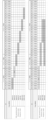
- FIG. 2 shows an example of setting channels according to the classification of the 920MHz band in Japan. More specifically, the upper part of FIG. 2 shows an example in which a 1 MHz wide channel is set in the 920 MHz band so that overlapping areas do not occur.
- the 1 MHz wide region spanning sub-ch29 to sub-ch33 is an NG region because it straddles the "passive priority” region and the "active priority” region.
- FIG. 2 shows an example in which a 2 MHz wide channel is set in the 920 MHz band, and an example in which a 4 MHz wide channel is set.
- the 2 MHz wide region spanning sub-ch24 to sub-ch33 is set as an NG region because it straddles the two regions of "passive priority" and "active priority".
- each channel When following the classification shown in Figure 2, a maximum of two 2MHz wide channels and only one 4MHz wide channel can be prepared. In other words, in order to provide four independent channels in the 920 MHz band that do not overlap, each channel must be set to a width of 1 MHz. In such a setting, the frequency width that is simultaneously utilized is only 2 MHz, and the wide frequency band shown in FIG. 2 cannot be fully utilized.
- the present disclosure has been made in view of the above-mentioned problems, and provides for appropriately controlling the transition timing of multiple channels so that multiple wireless communication modules placed in close proximity can fully utilize the frequency band.
- the first objective is to provide a wireless communication device.
- the present disclosure also provides a wireless communication method for appropriately controlling the transition timing of multiple channels so that multiple wireless communication modules placed in close proximity can fully utilize the frequency band. This is the second purpose.
- the present disclosure also provides a wireless communication system that can appropriately control the transition timing of multiple channels so that multiple wireless communication modules placed in close proximity can fully utilize the frequency band. is the third purpose.
- a first aspect includes a first wireless communication module that performs wireless communication with a communication device belonging to a first communication group by switching between a plurality of channels that do not have overlapping frequency ranges; a second wireless communication module that performs wireless communication with a communication device belonging to a second communication group by switching the plurality of channels; a control circuit that issues a command to the first wireless communication module and the second wireless communication module to specify a channel to be used for communication and a channel switching timing;
- the first wireless communication module and the second wireless communication module are Executing a process of relaying packets between a communication device belonging to the first communication group and a communication device belonging to the second communication group, In response to the said directive, A process of switching channels in synchronization with each other, A process of selecting channels to be used for communication so that the channels used at the same time do not have overlapping areas with each other; It is preferable that the system be configured to run .
- a second aspect is a wireless communication method in which a wireless communication device relays communication between a communication device belonging to a first communication group and a communication device belonging to a second communication group
- the wireless communication device includes: a first wireless communication module that performs wireless communication with a communication device belonging to a first communication group by switching between a plurality of channels that do not have overlapping frequency ranges; a second wireless communication module that performs wireless communication with a communication device belonging to a second communication group by switching the plurality of channels; a control circuit that issues a command to the first wireless communication module and the second wireless communication module to specify a channel to be used for communication and a channel switching timing; The first wireless communication module and the second wireless communication module, Relaying packets between a communication device belonging to the first communication group and a communication device belonging to the second communication group; switching channels in synchronization with each other according to the instructions; Selecting channels to be used for communication in accordance with the instruction so that channels used at the same time do not have overlapping areas with each other; It is desirable to include.
- a third aspect is a wireless communication system including a communication device belonging to a first communication group, a communication device belonging to a second communication group, and a wireless communication device that relays communication between the two
- the wireless communication device includes: a first wireless communication module that performs wireless communication with a communication device belonging to a first communication group by switching between a plurality of channels that do not have overlapping frequency ranges; a second wireless communication module that performs wireless communication with a communication device belonging to a second communication group by switching the plurality of channels; a control circuit that issues a command to the first wireless communication module and the second wireless communication module to specify a channel to be used for communication and a channel switching timing;
- the first wireless communication module and the second wireless communication module are Executing a process of relaying packets between a communication device belonging to the first communication group and a communication device belonging to the second communication group, In response to the said directive, A process of switching channels in synchronization with each other, A process of selecting channels to be used for communication so that the channels used at the same time do
- the first to third aspects it is possible to use a wide channel by appropriately controlling the timing at which a plurality of wireless communication modules arranged in close proximity change channels. Therefore, according to this aspect, it is possible to appropriately avoid interference between a plurality of adjacently arranged wireless communication modules, and to expand communication capacity by efficiently utilizing frequencies.
- FIG. 3 is a timing chart showing how the two wireless communication modules NIC-1 and NIC-2 switch channels as appropriate.
- FIG. 3 is a diagram illustrating an example of setting channels according to the classification of the 920 MHz band in Japan.
- FIG. 1 is a block diagram showing the basic configuration of a wireless communication system according to Embodiment 1 of the present disclosure.
- 4 is a block diagram showing a detailed configuration of the wireless communication repeater shown in FIG. 3.
- FIG. 4 is a diagram showing how two communication groups communicate simultaneously in the wireless communication system shown in FIG. 3.
- FIG. 3 is a timing chart for explaining the characteristics of the wireless communication system according to Embodiment 1 of the present disclosure.
- 12 is a timing chart for explaining the characteristics of the wireless communication system according to Embodiment 2 of the present disclosure.
- FIG. 3 is a block diagram showing the basic configuration of a wireless communication system according to Embodiment 1 of the present disclosure.
- the wireless communication system of this embodiment includes a wireless communication repeater 10.
- the wireless communication repeater 10 includes a repeater SoC (System on Chip) 12 .
- the repeater SoC 12 transmits packets between a first wireless communication module NIC-1 (hereinafter simply referred to as NIC-1) and a second wireless communication module NIC-2 (hereinafter simply referred to as NIC-2). This is an integrated circuit for exchanging information.
- the repeater SoC 12 is equipped with various elements necessary to realize the above functions, such as a processor and memory.
- the NIC-1 is a wireless communication module for performing wireless communication with the wireless communication master device 14.
- the NIC-2 is a wireless communication module for performing wireless communication with the wireless communication handset 16.
- the wireless communication system of this embodiment includes a base unit 14 and a slave unit 16, and may include a plurality of slave units 16. Although the base unit 14 and the slave unit 16 are separated from each other to the extent that direct communication is not possible, they can communicate with each other by interposing the wireless communication repeater 10.
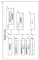
- FIG. 4 is a block diagram for explaining the configuration of the wireless communication repeater 10 in more detail.
- the wireless communication repeater 10 includes a communication bus 18.
- a memory 22 is connected to the communication bus 18 along with a control circuit 20 .
- the memory 22 stores control programs and management information.
- the control circuit 20 includes a processor, and is realized by the processor using the above management information and the like to execute processing in accordance with the above control program.
- the control program can be provided via a computer-readable recording medium and can also be provided via a network.
- a wired communication module 24 and a drive circuit 26 are also connected to the communication bus 18.
- the wireless communication repeater 10 can establish wired communication with an external device via the wired communication module 24 .
- the drive circuit 26 has a built-in storage medium for storing various data.
- a user interface 28 and a timer 30 are also connected to the communication bus 18.
- the user interface 28 is used for various input operations on the wireless communication repeater 10. Further, the timer 30 is used for various counts required in connection with communication.
- NIC-1 and NIC-2 which are also shown in FIG. 3, are further connected to the communication bus 18.
- the NIC-1 is a wireless communication module for establishing wireless communication between the wireless communication repeater 10 and the base unit 14.
- the NIC-2 is a wireless communication module for establishing wireless communication between the wireless communication repeater 10 and the handset 16.
- Both NIC-1 and NIC-2 can be used by switching between a plurality of channels in accordance with commands provided from the control circuit 20. For example, if the wireless communication system of this embodiment uses the 920 MHz band in Japan, a plurality of channels that can be set according to the classification shown in FIG. 2 can be switched and used as appropriate. Specifically, when the control circuit 20 requests the use of a 1 MHz width spanning sub-ch24 to sub-ch28, NIC-1 and NIC-2 use that area as a single channel. Furthermore, if it is required to use a 4 MHz width spanning sub-ch34 to sub-ch53, that area is used as a single channel. Furthermore, NIC-1 and NIC-2 can change the channel used at the timing specified by the control circuit 20.
- FIG. 5 shows a state in which a first communication group including NIC-1 and base unit 14 and a second communication group including NIC-2 and slave unit 16 are performing wireless communication at the same time.
- the first communication group uses channel #1 and the second communication group uses channel #2.
- Channel #1 and channel #2 are independent channels with no frequency overlap.
- the commands provided by the control circuit 20 of the repeater SoC 12 to the NIC-1 are also provided from the NIC-1 to the base unit 14 belonging to the same communication group. Therefore, the NIC-1 and the base unit 14 can perform wireless communication using a channel that is compatible with the commands from the control circuit 20.
- a command issued from the control circuit 20 to the NIC-2 is transmitted to all slave units 16 belonging to the same communication group as the NIC-2. Thereby, the NIC-2 and all slave devices 16 can perform wireless communication using a channel that is compatible with the commands of the control circuit 20.
- FIG. 6 is a timing chart for explaining the characteristics of the wireless communication system of this embodiment.
- FIG. 6 shows how NIC-1 uses channel #1 for a usage time a, and NIC-2 uses channel #2 for the same period. Furthermore, FIG. 6 shows how, after channel switching time c has elapsed, NIC-1 uses channel #2 for a usage time b, and NIC-2 uses channel #1 for the same period. .
- NIC-1 sequentially executes the following processes.
- (1-1) At the start timing of monitoring time d, communication using channel #1 is started with base unit 14.
- (1-2) Maintain channel #1 until usage time a has elapsed.
- (1-3) During the usage time a, the total transmission time is monitored, and the amount of transmitted packets is limited so that the duty ratio during the monitoring time d does not exceed 10%. That is, when the transmission time of NIC-1 reaches "d/10" during the usage time a, subsequent packet transmission is stopped.
- (1-4) When the usage time a has elapsed, stop communication using channel #1 and wait for the channel switching time c to elapse.
- the NIC-2 receives the above command from the control circuit 20 and executes the following processing.
- (2-1) At the start timing of monitoring time d, that is, in synchronization with NIC-1 starting communication on channel #1, start communication using channel #2 with slave unit 16. .
- (2-3) Maintain channel #2 until usage time a has elapsed.
- (2-3) During the usage time a, monitor the total transmission time and limit the amount of transmitted packets so that the duty ratio during the monitoring time d does not exceed 10%.
- (2-4) When the usage time a has elapsed, stop communication using channel #2 and wait for the channel switching time c to elapse. (2-5) After the switching time c has elapsed, communication with the handset 16 is resumed on channel #1.
- the wireless communication system of this embodiment is assumed to be used in a frequency band where transmission restrictions are imposed, such as the 920 MHz band in Japan.
- a restriction is imposed on all communication devices included in this system such that the duty ratio of the total transmission time on a single channel is 10% or less.
- the upper limit of the duty ratio is allowed to be up to 20%, provided that switching to a channel that does not have an overlapping area is performed.
- the above-mentioned monitoring time d is a unit time for monitoring the transmission duty ratio, and is, for example, "1 hour".
- a 10% duty ratio can be given to NIC-1 on each channel by processing (1-1) to (1-8) above. .
- a maximum duty ratio of 20% can be given to NIC-1.
- a maximum duty ratio of 20% can be given to NIC-2 by processing (2-1) to (2-8) above. I can do it.
- NIC-1 and NIC-2 switch channels at the same timing. Therefore, the period in which NIC-1 uses channel #1 and the period in which NIC-2 uses channel #1 do not overlap. The same applies to channel #2. Therefore, according to the operation example shown in FIG. 6, if only two independent channels with no overlapping areas can be prepared, signal interference between the first communication group and the second communication group can be prevented in all periods. can be avoided.
- the control circuit 20 provides the NIC-1 and NIC-2 with a command in which a width of 2 MHz is assigned to each of channel #1 and channel #2.
- a wide frequency range covering a total of 4 MHz can be utilized during usage times a and b.
- the range width that can be used simultaneously is 2 MHz, so the system of this embodiment significantly improves frequency usage efficiency. If frequency usage efficiency improves, communication capacity will also expand. Therefore, according to this embodiment, the communication capacity of the entire system can be significantly expanded.
- Embodiment 2 [Configuration of Embodiment 2] Next, a second embodiment of the present disclosure will be described with reference to FIG. 7 together with FIGS. 2 to 5.
- the wireless communication system of this embodiment can be realized by the hardware configuration shown in FIGS. 3 and 4, as in the case of Embodiment 1. Also in this embodiment, as shown in FIG. 5, the first communication group including NIC-1 and the base unit 14 and the second communication group including NIC-2 and the slave unit 16 do not interfere with each other. Communicate simultaneously using channels.
- the first communication group and the second communication group communicate using channel #1 and channel #2, each having a width of 2 MHz.
- channel #1 and channel #2 each having a width of 2 MHz.
- Japan's 920MHz band only one 4MHz wide channel can be prepared without creating overlapping bands. Therefore, in the method of switching and using a plurality of 4 MHz wide channels, the occurrence of overlapping areas is unavoidable, and the maximum transmission duty is 10%. Furthermore, since interference occurs between the two communication groups, retransmission requests also occur, making it difficult to secure sufficient capacity. For these reasons, the operation of switching between two independent channels with a width of 2 MHz is useful for increasing frequency usage efficiency.
- FIG. 7 shows an example of a timing chart when NIC-1 and NIC-2 switch and use channel #1 having a width of 4 MHz and channel #2 having a width of 1 MHz.
- the wireless communication repeater 10 causes each of NIC-1 and NIC-2 to execute switching between channel #1 and channel 2 so that the state shown in FIG. 7 is realized.
- the efficiency of frequency use is further improved compared to the first embodiment.
- the NIC-2 may communicate with a plurality of slave devices 16.
- Each of the plurality of handsets 16 can transmit at a duty ratio of 10%.
- the same restriction is imposed on transmission from NIC-1 to base unit 14, so if the transmission rates of the two communication groups are the same, the amount of packets received by NIC-2 is equal to the amount of packets sent by NIC-1. becomes more than Therefore, in this system, packet congestion is likely to occur at NIC-1.
- NIC-1 uses the 4 MHz band as described above, and NIC-2 uses the 1 MHz channel #1.
- the transmission rate r1_1 of NIC-1 is sufficiently larger than the transmission rate r2_2 of NIC-2. That is, during the usage time a, the plurality of child devices 16 upload packets to the NIC-2 at a small transmission rate r2_2, and on the other hand, the NIC-1 uploads packets to the base device 14 at a high transmission rate r1_1. In this case, packet congestion is unlikely to occur in the wireless communication repeater 10.
- the usage time a in which 4 MHz is allocated to NIC-1 is secured longer than the usage time b in which 1 MHz is allocated to NIC-1. According to this setting, it is possible to maintain a state in which congestion is unlikely to occur for a long time during the monitoring time d for the above-mentioned reason.
- the band that can be used simultaneously is set to 5 MHz, and the frequency usage efficiency is further increased compared to the case of the first embodiment. be able to. Furthermore, by setting the usage time a longer than the usage time b, congestion can be prevented from occurring in the wireless communication repeater 10 in an environment where the loads on the two wireless communication modules NIC-1 and NIC-2 are unbalanced. This can be effectively avoided.
- usage times a and b are specifically set so that the upper limit or average value of the transmission rate is constant between channel #1 and channel #2. It is set by the calculation below.
- r1_1 d1/a...(1)
- r1_2 d2/b...(2)
- usage times a and b are set so as to satisfy equations (5) and (6) above. Therefore, according to the wireless communication system of this embodiment, in addition to being able to efficiently utilize a wide frequency band and suppressing congestion at the wireless communication repeater 10, the user can experience changes in communication quality. can be sufficiently suppressed.
- Wireless communication repeater 12
- Repeater SoC System on Chip
- Master device 16
- Child device 20
- Control circuit 22
- Memory NIC-1, NIC-2 Wireless communication module (Network Interface Card or Network Interface Controller)
Landscapes
- Engineering & Computer Science (AREA)
- Computer Networks & Wireless Communication (AREA)
- Signal Processing (AREA)
- Mobile Radio Communication Systems (AREA)
Abstract
Description
前記複数のチャネルを切り替えて第二の通信グループに属する通信装置と無線通信を行なう第二の無線通信モジュールと、
前記第一の無線通信モジュールおよび前記第二の無線通信モジュールに、通信に用いるチャネルとチャネルの切り替えタイミングとを指定する指令を発する制御回路と、を備え、
前記第一の無線通信モジュールおよび前記第二の無線通信モジュールは、
前記第一の通信グループに属する通信装置と、前記第二の通信グループに属する通信装置との間でパケットを中継する処理を実行すると共に、
前記指令を受けて、
互いに同期してチャネルの切り替えを行う処理と、
同時に使用されるチャネルが互いに重複域を持たないもの同士となるように、通信に用いるチャネルを選択する処理と、
を実行するように構成されていることが望ましい。
前記無線通信装置は、
周波数の重複域を持たない複数のチャネルを切り替えて第一の通信グループに属する通信装置と無線通信を行なう第一の無線通信モジュールと、
前記複数のチャネルを切り替えて第二の通信グループに属する通信装置と無線通信を行なう第二の無線通信モジュールと、
前記第一の無線通信モジュールおよび前記第二の無線通信モジュールに、通信に用いるチャネルとチャネルの切り替えタイミングとを指定する指令を発する制御回路と、を備え、
前記第一の無線通信モジュールおよび前記第二の無線通信モジュールが、
前記第一の通信グループに属する通信装置と、前記第二の通信グループに属する通信装置との間でパケットを中継するステップと、
前記指令に従って、互いに同期してチャネルの切り替えを行うステップと、
前記指令に従って、同時に使用されるチャネルが互いに重複域を持たないもの同士となるように、通信に用いるチャネルを選択するステップと、
を含むことが望ましい。
前記無線通信装置は、
周波数の重複域を持たない複数のチャネルを切り替えて第一の通信グループに属する通信装置と無線通信を行なう第一の無線通信モジュールと、
前記複数のチャネルを切り替えて第二の通信グループに属する通信装置と無線通信を行なう第二の無線通信モジュールと、
前記第一の無線通信モジュールおよび前記第二の無線通信モジュールに、通信に用いるチャネルとチャネルの切り替えタイミングとを指定する指令を発する制御回路と、を備え、
前記第一の無線通信モジュールおよび前記第二の無線通信モジュールは、
前記第一の通信グループに属する通信装置と、前記第二の通信グループに属する通信装置との間でパケットを中継する処理を実行すると共に、
前記指令を受けて、
互いに同期してチャネルの切り替えを行う処理と、
同時に使用されるチャネルが互いに重複域を持たないもの同士となるように、通信に用いるチャネルを選択する処理と、
を実行するように構成されていることが望ましい。
[実施の形態1の構成]
図3は、本開示の実施の形態1の無線通信システムの基本的な構成を示すブロック図である。図3に示すように、本実施形態の無線通信システムは、無線通信中継器10を備えている。無線通信中継器10は、中継器SoC(System on Chip)12を備えている。中継器SoC12は、第一の無線通信モジュールNIC-1(以下、単にNIC-1と称す)と、第二の無線通信モジュールNIC-2(以下、単にNIC-2と称す)との間でパケットの受け渡しを行うための集積回路である。中継器SoC12には、プロセッサやメモリなど、上記の機能を実現するために必要な様々な素子が搭載されている。
図6は、本実施形態の無線通信システムの特徴を説明するためのタイミングチャートである。図6は、NIC-1が、利用時間aの間チャネル#1を使用し、同期間に亘ってNIC-2がチャネル#2を使用する様子を示している。また、図6は、チャネル切り替え時間cの経過後、利用時間bの間NIC-1がチャネル#2を使用し、同期間に亘ってNIC-2がチャネル#1を使用する様子を示している。
(1-1)監視時間dの開始タイミングにおいて、チャネル#1を使った通信を親機14との間で開始する。
(1-2)利用時間aが経過するまでチャネル#1を維持する。
(1-3)利用時間aの間、送信時間の総和を監視して、監視時間dにおけるデューティ比が10%を超えないように送信パケットの量を制限する。つまり、利用時間aの間にNIC-1の送信時間が「d/10」に達したら、以後のパケット送信を停止する。
(1-4)利用時間aが経過したらチャネル#1による通信を停止して、チャネル切り替え時間cの経過を待つ。
(1-5)切り替え時間cが経過したら、チャネル#2で親機14との通信を再開する。
(1-6)利用時間bの間、送信時間の総和を監視して、監視時間dにおけるデューティ比が10%を超えないように送信パケットの量を制限する。
(1-7)利用時間bが経過したらチャネル#2による通信を停止して、チャネル切り替え時間cの経過を待つ。
(1-8)以後、上記(1-1)~(1-7)の処理を繰り返し実行する。
(2-1)監視時間dの開始タイミングにおいて、つまり、NIC-1がチャネル#1の通信を開始するのと同期して、チャネル#2を使った通信を子機16との間で開始する。
(2-3)利用時間aが経過するまでチャネル#2を維持する。
(2-3)利用時間aの間、送信時間の総和を監視して、監視時間dにおけるデューティ比が10%を超えないように送信パケットの量を制限する。
(2-4)利用時間aが経過したらチャネル#2による通信を停止して、チャネル切り替え時間cの経過を待つ。
(2-5)切り替え時間cが経過したら、チャネル#1で子機16との通信を再開する。
(2-6)利用時間bの間、送信時間の総和を監視して、監視時間dに対するデューティ比が10%を超えないように送信パケットの量を制限する。
(2-7)利用時間bが経過したらチャネル#1による通信を停止して、チャネル切り替え時間cの経過を待つ。
(2-8)以後、上記(2-1)~(2-7)の処理を繰り返し実行する。
[実施の形態2の構成]
次に、図2乃至図5と共に図7を参照して、本開示の実施の形態2について説明する。
本実施の形態の無線通信システムは、実施の形態1の場合と同様に、図3および図4に示すハードウェア構成により実現することができる。また、本実施形態においても、図5に示すように、NIC-1と親機14を含む第一の通信グループと、NIC-2と子機16を含む第二の通信グループは、互いに干渉しないチャネルを用いて同時に通信を行なう。
図7は、4MHz幅のチャネル#1と1MHz幅のチャネル#2とをNIC-1およびNIC-2がそれぞれ切り替えて用いる場合のタイミングチャートの一例を示す。本実施形態において、無線通信中継器10は、図7に示す状態が実現されるように、NIC-1およびNIC-2のそれぞれにチャネル#1とチャネル2の切り替えを実行させる。これにより、本実施形態では、周波数利用の効率化が、実施の形態1の場合に比して更に高められている。
ところで、上記のように、4MHzのチャネル#1と1MHzのチャネル#2を切り替えて用いることとすると、チャネルの切り替えに伴って、ユーザに、通信品質の変化が体感として伝わる事態が生じ得る。本実施形態では、このような体感変化を抑制するため、送信レートの上限または平均値がチャネル#1の場合とチャネル#2の場合とで一定になるように、利用時間aおよびbが、具体的には下記の計算により設定される。
・NIC-1がチャネル#1(4MHz)で送信可能な送信レート:r1_1
・NIC-1がチャネル#2(1MHz)で送信可能な送信レート:r1_2
・チャネル#1が10%のデューティ比で送信可能なデータ量:d1[byte]
・チャネル#2が10%のデューティ比で送信可能なデータ量:d2[byte]
r1_1=d1/a ・・・(1)
r1_2=d2/b ・・・(2)
r1_1 = r1_2 ・・・(3)
d1/a=d2/b ・・・(4)
a=d1/d2*b ・・・(5)
d=a+b+c ・・・(6)
12 中継器SoC(System on Chip)
14 親機
16 子機
20 制御回路
22 メモリ
NIC-1、NIC-2 無線通信モジュール(Network Interface CardまたはNetwork Interface Controller)
Claims (8)
- 周波数の重複域を持たない複数のチャネルを切り替えて第一の通信グループに属する通信装置と無線通信を行なう第一の無線通信モジュールと、
前記複数のチャネルを切り替えて第二の通信グループに属する通信装置と無線通信を行なう第二の無線通信モジュールと、
前記第一の無線通信モジュールおよび前記第二の無線通信モジュールに、通信に用いるチャネルとチャネルの切り替えタイミングとを指定する指令を発する制御回路と、を備え、
前記第一の無線通信モジュールおよび前記第二の無線通信モジュールは、
前記第一の通信グループに属する通信装置と、前記第二の通信グループに属する通信装置との間でパケットを中継する処理を実行すると共に、
前記指令を受けて、
互いに同期してチャネルの切り替えを行う処理と、
同時に使用されるチャネルが互いに重複域を持たないもの同士となるように、通信に用いるチャネルを選択する処理と、
を実行するように構成されている無線通信装置。 - 前記第一の無線通信モジュールおよび前記第二の無線通信モジュールは、
通信に用いるチャネル毎に送信時間を監視する処理と、
前記送信時間が、単一チャネルについての制限時間に達したら当該チャネルでの以後の送信を停止する処理と、
を更に実行するように構成されている請求項1に記載の無線通信装置。 - 単一の無線装置が単一チャネルでデータを送信する時間に制限が課されており、かつ、チャネルが切り替えられると、新たに前記制限まで送信が許容される環境で用いられる請求項2に記載の無線通信装置。
- 前記複数のチャネルは第一のチャネルと第二のチャネルであり、
前記第一のチャネルと前記第二のチャネルは、同じ幅の周波数帯域を夫々有している請求項1に記載の無線通信装置。 - 前記複数のチャネルは第一のチャネルと第二のチャネルであり、
前記第一のチャネルは、前記第二のチャネルに比して広域の周波数帯域を有している請求項1に記載の無線通信装置。 - 前記第一の無線通信モジュールには、前記第二の無線通信モジュールに比してパケットの輻輳が生じ易く、
前記第一の無線通信モジュールが前記第一のチャネルを使用する第一の利用時間は、前記第一の無線通信モジュールが前記第二のチャネルを使用する第二の利用時間に比して長く設定されている請求項5に記載の無線通信装置。 - 第一の通信グループに属する通信装置と第二の通信グループに属する通信装置との通信を無線通信装置が中継する無線通信方法であって、
前記無線通信装置は、
周波数の重複域を持たない複数のチャネルを切り替えて第一の通信グループに属する通信装置と無線通信を行なう第一の無線通信モジュールと、
前記複数のチャネルを切り替えて第二の通信グループに属する通信装置と無線通信を行なう第二の無線通信モジュールと、
前記第一の無線通信モジュールおよび前記第二の無線通信モジュールに、通信に用いるチャネルとチャネルの切り替えタイミングとを指定する指令を発する制御回路と、を備え、
前記第一の無線通信モジュールおよび前記第二の無線通信モジュールが、
前記第一の通信グループに属する通信装置と、前記第二の通信グループに属する通信装置との間でパケットを中継するステップと、
前記指令に従って、互いに同期してチャネルの切り替えを行うステップと、
前記指令に従って、同時に使用されるチャネルが互いに重複域を持たないもの同士となるように、通信に用いるチャネルを選択するステップと、
を含む無線通信方法。 - 第一の通信グループに属する通信装置と、第二の通信グループに属する通信装置と、両者間で通信を中継する無線通信装置とを含む無線通信システムであって、
前記無線通信装置は、
周波数の重複域を持たない複数のチャネルを切り替えて第一の通信グループに属する通信装置と無線通信を行なう第一の無線通信モジュールと、
前記複数のチャネルを切り替えて第二の通信グループに属する通信装置と無線通信を行なう第二の無線通信モジュールと、
前記第一の無線通信モジュールおよび前記第二の無線通信モジュールに、通信に用いるチャネルとチャネルの切り替えタイミングとを指定する指令を発する制御回路と、を備え、
前記第一の無線通信モジュールおよび前記第二の無線通信モジュールは、
前記第一の通信グループに属する通信装置と、前記第二の通信グループに属する通信装置との間でパケットを中継する処理を実行すると共に、
前記指令を受けて、
互いに同期してチャネルの切り替えを行う処理と、
同時に使用されるチャネルが互いに重複域を持たないもの同士となるように、通信に用いるチャネルを選択する処理と、
を実行するように構成されている無線通信システム。
Priority Applications (2)
| Application Number | Priority Date | Filing Date | Title |
|---|---|---|---|
| PCT/JP2022/017858 WO2023199488A1 (ja) | 2022-04-14 | 2022-04-14 | 無線通信装置、無線通信方法および無線通信システム |
| JP2024514756A JP7782684B2 (ja) | 2022-04-14 | 2022-04-14 | 無線通信装置、無線通信方法および無線通信システム |
Applications Claiming Priority (1)
| Application Number | Priority Date | Filing Date | Title |
|---|---|---|---|
| PCT/JP2022/017858 WO2023199488A1 (ja) | 2022-04-14 | 2022-04-14 | 無線通信装置、無線通信方法および無線通信システム |
Publications (1)
| Publication Number | Publication Date |
|---|---|
| WO2023199488A1 true WO2023199488A1 (ja) | 2023-10-19 |
Family
ID=88329412
Family Applications (1)
| Application Number | Title | Priority Date | Filing Date |
|---|---|---|---|
| PCT/JP2022/017858 Ceased WO2023199488A1 (ja) | 2022-04-14 | 2022-04-14 | 無線通信装置、無線通信方法および無線通信システム |
Country Status (2)
| Country | Link |
|---|---|
| JP (1) | JP7782684B2 (ja) |
| WO (1) | WO2023199488A1 (ja) |
Citations (3)
| Publication number | Priority date | Publication date | Assignee | Title |
|---|---|---|---|---|
| US20120113918A1 (en) * | 2010-11-05 | 2012-05-10 | Interdigital Patent Holdings, Inc. | Silent period method and apparatus for dynamic spectrum management |
| WO2021161863A1 (ja) * | 2020-02-13 | 2021-08-19 | パナソニックIpマネジメント株式会社 | 無線通信装置、無線通信方法及び無線通信システム |
| WO2021250825A1 (ja) * | 2020-06-10 | 2021-12-16 | 日本電信電話株式会社 | 通信方法、及び端末 |
Family Cites Families (1)
| Publication number | Priority date | Publication date | Assignee | Title |
|---|---|---|---|---|
| JP5685418B2 (ja) | 2010-11-10 | 2015-03-18 | ホーチキ株式会社 | 無線中継器 |
-
2022
- 2022-04-14 WO PCT/JP2022/017858 patent/WO2023199488A1/ja not_active Ceased
- 2022-04-14 JP JP2024514756A patent/JP7782684B2/ja active Active
Patent Citations (3)
| Publication number | Priority date | Publication date | Assignee | Title |
|---|---|---|---|---|
| US20120113918A1 (en) * | 2010-11-05 | 2012-05-10 | Interdigital Patent Holdings, Inc. | Silent period method and apparatus for dynamic spectrum management |
| WO2021161863A1 (ja) * | 2020-02-13 | 2021-08-19 | パナソニックIpマネジメント株式会社 | 無線通信装置、無線通信方法及び無線通信システム |
| WO2021250825A1 (ja) * | 2020-06-10 | 2021-12-16 | 日本電信電話株式会社 | 通信方法、及び端末 |
Non-Patent Citations (2)
| Title |
|---|
| ARIB ORGANIZATION: "920MHz-Band Telemeter, Telecontrol and Data Transmission Radio Equipment", ARIB, ASSOCIATION OF RADIO INDUSTRIES AND BUSINESSES, NITTOCHI BLDG., 1-4-1, KASUMIGASEKI, CHIYODAKU, TOKYO 100-0013, JAPAN, no. v1.4, 21 September 2021 (2021-09-21), Nittochi Bldg., 1-4-1, Kasumigaseki, Chiyodaku, Tokyo 100-0013, Japan , pages 2.24 - 2.29, 3.14 - 3.16, 4.15, XP017862164 * |
| FUJITA, KOSUKE, ET AL.: "1V-05 Transmission timing adjustment to improve throughput in sensor networks using specific low power radio with transmission time controller", PROCEEDINGS OF THE 82ND NATIONAL CONVENTION OF IPSJ; KANAZAWA INSTITUTE OF TECHNOLOGY; MARCH 5-7, 2020, vol. 82, no. 3, 20 February 2020 (2020-02-20) - 7 March 2020 (2020-03-07), pages 3 - 3-92, XP009549623 * |
Also Published As
| Publication number | Publication date |
|---|---|
| JPWO2023199488A1 (ja) | 2023-10-19 |
| JP7782684B2 (ja) | 2025-12-09 |
Similar Documents
| Publication | Publication Date | Title |
|---|---|---|
| TWI558119B (zh) | 具有多個同質無線電共存的無線感測器基地台 | |
| TWI555427B (zh) | 能夠區別出功率敏感無線感測器且對其提供分開處理的無線路由器或住宅閘道 | |
| US12101716B2 (en) | User equipment involved in transmitting UE assistance information | |
| US10652912B2 (en) | Smart radio arbiter with conflict resolution based on timing predictability | |
| WO2017196551A1 (en) | Single radio switching between multiple wireless links | |
| EP2832168A1 (en) | Dynamic setting of transmisison time in a contention based wireless system | |
| JP7424319B2 (ja) | 通信装置および通信方法 | |
| JP6585739B2 (ja) | 無線通信システム、無線通信端末および無線通信方法 | |
| JP7782684B2 (ja) | 無線通信装置、無線通信方法および無線通信システム | |
| KR20090060050A (ko) | 이중 광대역 무선 접속 장치 및 그의 접속 제어 방법 | |
| US7840183B2 (en) | Short-range wireless communication device | |
| EP3813267B1 (en) | Radio module, method to operate a radio module, radio terminal, method to operate a radio terminal | |
| JP2008085794A (ja) | 無線通信装置およびその制御方法 | |
| JP7683728B2 (ja) | 無線通信監理方法、無線通信監理システムおよび無線通信監理装置 | |
| US20140323177A1 (en) | Apparatus and Method of Discontinuous Operation in LTE on Shared Band | |
| JP2025530914A (ja) | アップリンク伝送方法および装置 | |
| KR20250162267A (ko) | 데이터의 스케줄링을 수행하기 위한 장치 및 방법 | |
| WO2025200686A1 (zh) | 一种通信方法及装置 | |
| WO2025103312A1 (zh) | 一种通信方法及装置 | |
| WO2025161954A1 (zh) | 一种切换方法和通信装置 | |
| WO2024239331A1 (zh) | 用于侧行通信的方法及装置 | |
| WO2022264334A1 (ja) | 無線通信システム、無線通信方法、アクセスポイント装置およびプログラム | |
| WO2025218565A1 (zh) | 通信方法和通信装置 | |
| WO2025092762A1 (zh) | 一种资源池选择或重选方法及装置 | |
| JP2004146980A (ja) | 無線パケット通信方法及び無線パケット通信装置 |
Legal Events
| Date | Code | Title | Description |
|---|---|---|---|
| 121 | Ep: the epo has been informed by wipo that ep was designated in this application |
Ref document number: 22937467 Country of ref document: EP Kind code of ref document: A1 |
|
| ENP | Entry into the national phase |
Ref document number: 2024514756 Country of ref document: JP Kind code of ref document: A |
|
| WWE | Wipo information: entry into national phase |
Ref document number: 18855655 Country of ref document: US |
|
| NENP | Non-entry into the national phase |
Ref country code: DE |
|
| 122 | Ep: pct application non-entry in european phase |
Ref document number: 22937467 Country of ref document: EP Kind code of ref document: A1 |