WO2023195089A1 - ネットワーク管理における経路情報のアドバタイズ - Google Patents
ネットワーク管理における経路情報のアドバタイズ Download PDFInfo
- Publication number
- WO2023195089A1 WO2023195089A1 PCT/JP2022/017144 JP2022017144W WO2023195089A1 WO 2023195089 A1 WO2023195089 A1 WO 2023195089A1 JP 2022017144 W JP2022017144 W JP 2022017144W WO 2023195089 A1 WO2023195089 A1 WO 2023195089A1
- Authority
- WO
- WIPO (PCT)
- Prior art keywords
- network
- information
- route information
- network management
- management device
- Prior art date
- Legal status (The legal status is an assumption and is not a legal conclusion. Google has not performed a legal analysis and makes no representation as to the accuracy of the status listed.)
- Ceased
Links
Images



Classifications
-
- H—ELECTRICITY
- H04—ELECTRIC COMMUNICATION TECHNIQUE
- H04L—TRANSMISSION OF DIGITAL INFORMATION, e.g. TELEGRAPHIC COMMUNICATION
- H04L45/00—Routing or path finding of packets in data switching networks
- H04L45/74—Address processing for routing
- H04L45/745—Address table lookup; Address filtering
- H04L45/748—Address table lookup; Address filtering using longest matching prefix
-
- H—ELECTRICITY
- H04—ELECTRIC COMMUNICATION TECHNIQUE
- H04L—TRANSMISSION OF DIGITAL INFORMATION, e.g. TELEGRAPHIC COMMUNICATION
- H04L45/00—Routing or path finding of packets in data switching networks
- H04L45/02—Topology update or discovery
-
- H—ELECTRICITY
- H04—ELECTRIC COMMUNICATION TECHNIQUE
- H04L—TRANSMISSION OF DIGITAL INFORMATION, e.g. TELEGRAPHIC COMMUNICATION
- H04L45/00—Routing or path finding of packets in data switching networks
- H04L45/02—Topology update or discovery
- H04L45/04—Interdomain routing, e.g. hierarchical routing
-
- H—ELECTRICITY
- H04—ELECTRIC COMMUNICATION TECHNIQUE
- H04L—TRANSMISSION OF DIGITAL INFORMATION, e.g. TELEGRAPHIC COMMUNICATION
- H04L45/00—Routing or path finding of packets in data switching networks
- H04L45/12—Shortest path evaluation
- H04L45/123—Evaluation of link metrics
-
- H—ELECTRICITY
- H04—ELECTRIC COMMUNICATION TECHNIQUE
- H04L—TRANSMISSION OF DIGITAL INFORMATION, e.g. TELEGRAPHIC COMMUNICATION
- H04L61/00—Network arrangements, protocols or services for addressing or naming
Definitions
- the present invention relates to technology for advertising route information.
- a technology in which multiple prefixes are aggregated, replaced with a single route, and information on the aggregated route is advertised to other devices.
- a router constituting a network aggregates a plurality of IP prefixes of networks connectable to the router, and advertises the aggregated IP prefixes to routers of other networks (Patent Document 1).
- a router in a second network obtains aggregated IP prefixes advertised from each of a plurality of border routers in a first network (a plurality of edge routers in the first network).
- the aggregated IP prefix may indicate information of the same aggregated prefix indicating the first network.
- a router in a second network sends a packet received from a terminal in the second network to a terminal in the first network, it obtains only the aggregated IP prefix indicating the first network. , forwards the packet to one of the plurality of border routers in the first network.
- the router in the first network to which the packet was forwarded is a router far from the router connected to the destination terminal, unnecessary packets may be transferred between the routers in the first network. Transfer is necessary, and the packet will have to take a long detour to reach the destination terminal. Additionally, if the router in the first network to which the packet is forwarded is different from the router connected to the destination terminal, and the first network is disconnected, the packet will be forwarded to the destination terminal. There may be cases where this is not possible.
- the present invention aims to provide a route information advertising technique for streamlining network operation.
- one aspect of the network management device includes an acquisition unit that acquires information on IP prefixes managed in each of one or more subnetworks in a first network as route information; an aggregation unit that generates aggregated IP prefix information, which aggregates information on IP prefixes managed in each of one or more subnetworks, as aggregated route information; and an advertising unit that advertises to a different second network.
- the advertising unit may also advertise location information of each of the one or more subnetworks.
- the location information may include a distance between a predetermined location in each of the one or more subnetworks and the location of the network management device.
- another aspect of the network management device provides packets sent from a terminal device in a first network to another terminal device in a second network different from the first network.
- an acquisition unit that acquires route information and aggregated route information advertised from each of the plurality of network devices of the second network; and an acquisition unit that acquires route information and aggregated route information based on the route information and the aggregated route information.
- a determining unit that determines a device to which the packet is to be forwarded in the second network, and a forwarding unit that forwards the packet to the determined device, and the route information is transmitted to the second network.
- Information on IP prefixes managed in each of one or more subnetworks in the network, and the aggregate route information is information on an aggregated IP prefix that aggregates information on IP prefixes managed in each of the one or more subnetworks. It is.
- the acquisition unit acquires location information of each of the one or more subnetworks, and the determination unit determines the transfer destination based on the route information, the aggregated route information, and the location information. equipment can be determined.
- the location information may include a distance between a predetermined location in each of the one or more subnetworks and the location of the network management device.
- one aspect of the network management method includes an acquisition step of acquiring information on IP prefixes managed in each of one or more subnetworks in a first network as route information; an aggregation step of generating aggregated IP prefix information, which is aggregation of information on IP prefixes managed in each of one or more subnetworks, as aggregated route information; and a step of combining the route information and the aggregated route information with a first network and an advertising step of advertising to a different second network.
- another aspect of the network management method provides packets sent from a terminal device in a first network to another terminal device in a second network different from the first network.
- Information on IP prefixes managed in each of one or more subnetworks in the network, and the aggregate route information is information on an aggregated IP prefix that aggregates information on IP prefixes managed in each of the one or more subnetworks. It is.
- one aspect of the storage medium according to the present invention is a storage medium that stores a control program for causing a computer to execute network management processing, the program causing the computer to perform a first Acquisition processing that acquires information on IP prefixes managed in each of one or more subnetworks in a network as route information, and an acquisition process that aggregates information on IP prefixes managed in each of the one or more subnetworks in the network.
- This is for executing processing including aggregation processing for generating information as aggregated route information, and advertising processing for advertising the route information and the aggregated route information to a second network different from the first network.
- another aspect of the storage medium is a storage medium that stores a control program for causing a computer to execute a network management process, the program causing the computer to perform a first a reception process for receiving a packet destined for another terminal device in a second network different from the first network from a terminal device in a network; an acquisition process for acquiring route information and aggregated route information, and a determination process for determining a device to which the packet is transferred in the second network based on the route information and the aggregated route information; and a transfer process of transferring the packet to the determined device, and the route information is an IP address managed by each of one or more subnetworks in the second network.
- the aggregate route information is prefix information
- the aggregate route information is aggregate IP prefix information that aggregates information on IP prefixes managed in each of the one or more subnetworks.
- a route information advertising technique is provided to improve the efficiency of network operation.
- FIG. 1 shows an example of a network configuration according to an embodiment.
- FIG. 2 shows an example of the functional configuration of the network management device according to the embodiment.
- FIG. 3 is a diagram showing an example of the hardware configuration of the network management device according to the embodiment.
- FIG. 4 is a diagram illustrating an example of a processing flow according to the embodiment.
- FIG. 5A is a diagram for explaining an example of packet transfer at the time of network division according to the embodiment.
- FIG. 5B is a diagram for explaining an example of packet transfer at the time of network division according to the embodiment.
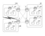
- FIG. 1 shows a network configuration according to this embodiment.
- the terminal devices 111, 112, 121, 122, 131, 132, 141, and 142 are communication devices that have a function of generating and transmitting packets (traffic) containing data.
- Network management devices 1 to 4 and 11 to 14 are communication devices that function as routers.
- the terminal devices 111, 112, 121, 122, 131, 132, 141, and 142 may be collectively referred to as the terminal device 111.
- the network management devices 1 to 4 and 11 to 14 can be collectively referred to as the network management device 1.
- the generated packet may be, for example, a packet that follows the IPv4 (Internet Protocol Version 4) protocol or a packet that follows the IPv6 protocol.
- IPv4 Internet Protocol Version 4
- the terminal device 111 is a mobile device such as a user equipment (UE), a mobile station (MS), a mobile station device, a mobile terminal, a subscriber unit, a subscriber station, a wireless terminal, or a mobile device. or a general term for fixed user end equipment.
- the terminal device 1 may be a device such as a cellular phone, a smartphone, a personal digital assistant (PDA), a tablet, a laptop, a handheld communication device, a handheld computing device, a satellite radio, a wireless modem card, or a CPE (Customer Premises Equipment). It's okay.
- the network management device 1 controls the transfer of the received packet by referring to the destination address (destination IP address) included in the packet. For example, when transmitting a packet generated by the terminal device 111 to the terminal device 132, the terminal device 111 transmits the packet to the network management device 11. Subsequently, the network management device 11 extracts the destination address from the packet received from the terminal device 111, and calculates the network address of the destination address. Thereafter, the network management device 11 refers to its own routing table, determines the network management device to which the packet is to be forwarded, and forwards the packet. In FIG. 1, for example, the network management device 11 transfers the packet to the network management device 1. Thereafter, the packet is transferred to the network management device 3 and the network management device 13, for example, based on the routing table possessed by each network management device, and finally reaches the terminal device 132.
- the destination address destination IP address
- the network management device 1 updates its own routing table. For this update, each network management device aggregates the IP prefixes managed by one or more networks (subnetworks) managed by each network management device itself (that is, its lower level), and Advertise (public relations) to the management device.
- the network management device 11 aggregates a plurality of IP prefixes in the network 110 including the IP prefixes of the terminal device 111 and the terminal device 112, generates an aggregated IP prefix, and communicates with the network management device 1 and network management. Advertise to device 2.
- the network management device 12 advertises an aggregated IP prefix, which is a collection of a plurality of IP prefixes in the network 120, to the network management device 1 and the network management device 2.
- the network management device 1 that has received the aggregated IP prefix of the network 110 and the network 120 aggregates a plurality of IP prefixes in the network 10 including the aggregated IP prefix, generates an aggregated IP prefix, and connects the network management device 3 and the network. Advertise to the management device 4.
- Such advertising procedure is the same for networks 20, 130, and 140.
- each network management device is configured to advertise not only the generated aggregated IP prefix but also the aggregated IP prefix in the underlying network.
- the network management device 1 is configured to advertise (leak) not only the aggregated IP prefix in the network 10 but also the aggregated IP prefixes in each of the networks 110 and 120. That is, the network management device 1 is configured to advertise a plurality of (aggregated) IP prefixes (a plurality of stages).
- FIG. 2 shows the functional configuration of the network management device 1 according to this embodiment.
- the network management devices 2 to 4 and 11 to 14 can also have a functional configuration similar to the configuration shown in FIG.
- the acquisition unit 21 acquires route information from devices in the lower network managed by the network management device 1.
- a plurality of IP prefixes in the network 10 including the aggregated IP prefixes generated by the network management device 11 and the network management device 12, are acquired as route information.
- a plurality of IP prefixes in the network 110 are acquired as route information.
- the aggregation unit 22 generates aggregated route information from the route information acquired by the acquisition unit 21.
- a plurality of IP prefixes in the network 10 are aggregated to generate an aggregated IP prefix as aggregated route information.
- a plurality of IP prefixes in the network 110 are aggregated, and the aggregated IP prefix is generated as aggregated route information.
- the advertising unit 23 advertises the aggregated route information generated by the aggregating unit 22. In this embodiment, the advertising unit 23 also advertises the route information acquired by the acquisition unit 21.
- the receiving unit 24 receives packets from devices in the lower network managed by the network management device 1.
- the determining unit 25 maintains a routing table of the network management device 1 itself, and determines the device to which the packet received by the receiving unit 24 is to be transferred based on the routing table.
- the determining unit 25 determines the transfer destination device according to the longest match rule. That is, when a plurality of available networks exist in the routing table, the determining unit 25 determines the destination route with the longest matching address bits (prefix length) of the destination network as the packet transfer destination.
- the transfer unit 26 transfers the packet received by the reception unit 24 to the packet transfer destination device determined by the determination unit 25.
- the advertising unit 23 is configured to advertise the aggregated route information generated by the aggregating unit 22 and the route information acquired by the acquiring unit 21.
- the prefix length of the aggregated IP prefixes aggregated by the network management device 1 is 32 (for example, 240b: ) and an IP prefix (aggregated route information) with a prefix length of 32.
- the network management device 3 and the network management device 4 to which these IP prefixes have been advertised can acquire information on IP prefixes not only in the network 10 but also in the networks 110 and 120.
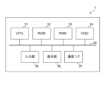
- FIG. 3 shows an example of the hardware configuration of the network management device 1 according to this embodiment.
- the network management devices 2 to 4 and 11 to 14 can also have a hardware configuration similar to the configuration shown in FIG.
- the network management device 1 according to this embodiment can be implemented on any computer or any other processing platform, single or multiple.
- the network management device 1 may be implemented in a general-purpose server device that constitutes a cloud, or may be implemented in a dedicated server device. Referring to FIG. 3, an example is shown in which the network management device 1 is implemented in a single computer, but the network management device 1 according to the present embodiment is implemented in a computer system including a plurality of computers. good. A plurality of computers may be connected to each other through a wired or wireless network so that they can communicate with each other.
- the network management device may include a CPU 31, a ROM 32, a RAM 33, an HDD 34, an input section 35, a display section 36, a communication I/F 37, and a system bus 38.
- the network management device 1 may also include external memory.
- a CPU (Central Processing Unit) 31 centrally controls operations in the network management device 1, and controls each component (32 to 37) via a system bus 38, which is a data transmission path.
- the ROM (Read Only Memory) 32 is a nonvolatile memory that stores control programs and the like necessary for the CPU 31 to execute processing.
- the program may be stored in a nonvolatile memory such as an HDD (Hard Disk Drive) 34 or an SSD (Solid State Drive), or an external memory such as a removable storage medium (not shown).
- a RAM (Random Access Memory) 33 is a volatile memory and functions as a main memory, work area, etc. of the CPU 31. That is, the CPU 31 loads necessary programs and the like from the ROM 32 into the RAM 33 when executing processing, and implements various functional operations by executing the programs and the like.
- the HDD 34 stores, for example, various data and information necessary when the CPU 31 performs processing using a program. Further, the HDD 34 stores various data, various information, etc. obtained by the CPU 31 performing processing using programs and the like.
- the input unit 35 is composed of a pointing device such as a keyboard and a mouse.
- the display unit 36 is composed of a monitor such as a liquid crystal display (LCD).
- the display unit 36 may provide a GUI (Graphical User Interface) for inputting various parameters, communication parameters used in communication with other devices, etc. to the communication device.
- the communication I/F 37 is an interface that controls communication between the network management device 1 and external devices.
- each element of the functional configuration of the network management device 1 shown in FIG. 2 can be realized by the CPU 31 executing a program.
- at least a portion of each element of the functional configuration of the network management device 1 may operate as dedicated hardware.
- the dedicated hardware operates under the control of the CPU 31.
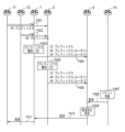
- FIG. 4 is a diagram showing an example of a processing flow according to this embodiment, and will be described with reference to the network configuration of FIG. 1.
- the acquisition unit 21 of the network management device 1 acquires the aggregated IP prefix (route information) advertised in F401 and F402.
- the advertising unit 23 of the network management device 1 advertises the aggregated IP prefix (route information) acquired from the network management devices 11 and 12 and the aggregated IP prefix (aggregated route information) generated in F403. do.
- the advertising unit 23 of the network management device 2 advertises the aggregated IP prefix (route information) acquired from the network management devices 11 and 12 and the aggregated IP prefix (aggregated route information) generated in F405. do.
- a packet to be transmitted to the terminal device 111 is generated in the terminal device 141, for example.
- the terminal device 141 generates a packet to be transmitted, and transmits the packet to the network management device 14.
- the receiving unit 24 of the network management device 14 receives the packet, and the transfer unit 26 transfers the packet to another network management device according to the routing table of the network management device 14 itself. In this example, it is assumed that the network management device 14 transfers the packet to the network management device 4.
- the receiving unit 24 of the network management device 4 receives the packet from the network management device 14.
- the determining unit 25 of the network management device 4 can determine to transfer the packet to the network management device 1 based on the various route information transmitted in F404 and F406. Subsequently, in F410, the transfer unit 26 of the network management device 4 transfers the packet to the network management device 1. In F411, the network management device 1 transfers the packet to the network management device 11 that manages the terminal device 111 that is the destination device of the packet. The network management device 11 transmits the packet to the terminal device 111 (not shown).
- the advertising units 23 of the network management device 1 and the network management device 2 may advertise cost information for the network management device in the lower network, along with the route information and the aggregated route information.
- Cost information generally refers to information (distance between a predetermined position in a source network and a predetermined position in a destination network) indicating a reachable distance (cost on a route) to a destination network.
- the network management device 11 may also advertise cost information for the network management device 11 (reaching distance from the network management device 11 to the network management device 1).
- the cost information may be set in advance in the system, or each network management device itself may be configured to acquire it using a predetermined method.
- the network management device 1 can also advertise the cost information for the network management device 11 acquired in F401.
- the network management device 12 can also advertise cost information (reaching distance from the network management device 12 to the network management device 2) to the network management device 12, and in F406, the network management device 2 Cost information may also be advertised.
- the network management device 4 can acquire cost information for each of the network management device 11 and the network management device 12.
- the cost information for each of the network management device 11 and the network management device 12 is also taken into consideration, and the packet is transferred from the network management device 4. That is, when the destination device of the packet is the terminal device 111, the packet is efficiently transferred so that the packet is transferred to the network management device 11 that manages the terminal device 111.
- the cost information may be information indicating (or including) the positional relationship (distance) between the network management device and a network management device above the network management device.
- the cost information for the network management device 11 may be information indicating (or including) the distance between a predetermined location in the network 110 and the location of the network management device 1.
- Advertising cost information to the network management device along with route information and aggregated route information is effective even when the network is partitioned.
- An example of packet transfer at the time of network division will be described with reference to FIGS. 5A and 5B.
- 5A and 5B are diagrams for explaining an example of packet transfer at the time of network division according to this embodiment.
- the network management device 14 receives the packet from the terminal device 141 and transfers it to the network management device 4.
- the network management device 4 determines the device to which the packet is to be transferred based on the cost information for each of the network management device 11 and the network management device 12, the destination prefix of the packet, the advertised route information, and the aggregated route information.
- the network management device 4 can transfer the packet to the network management device 1 that is closer to the network management device 11.
- the network management device 1 can transfer the packet to the network management device 11, and the network management device 11 can transfer it to the terminal device 111.
- the network management device 4 can transfer the packet to the network management device 1 instead of the network management device 2. The packet will be transferred successfully. Therefore, resistance to network failures is improved.
- each network management device can efficiently transfer packets.
- each network management device also advertises the reachable distance (cost information) from the network management device in the lower network to the network management device in the higher network, so that each network management device takes into account the cost information. It becomes possible to perform more efficient packet transfer. Through such processing, detours in packet transfer can be avoided, and packets can be delivered to the destination device even in the event of a network failure, so failure tolerance is improved.
- the network management device 1 advertises IP prefixes with two prefix lengths, but it may be configured to advertise IP prefixes with three or more prefix lengths.
- this embodiment is applicable to both IPv4 and IPv6.
- IPv6 since IP addresses can be assigned to more devices, there are many devices with the same prefix length, and the effects of the above embodiment can be more advantageously exerted.
- 11 to 14 network management device
- 111; 112; 121; 122; 131; 132; 141; 142 terminal device
- 21 acquisition unit
- 22 aggregation unit
- 23 advertising unit
- 25 Determination section
- 26 Transfer section
Landscapes
- Engineering & Computer Science (AREA)
- Computer Networks & Wireless Communication (AREA)
- Signal Processing (AREA)
- Data Exchanges In Wide-Area Networks (AREA)
Abstract
Description
また、パケットが転送された第1のネットワークにおけるルータが、宛先の端末に接続されているルータと異なるルータであり、かつ、第1のネットワークが分断した場合には、宛先の端末までパケットを転送できない場合も生じうる。
図1に、本実施形態によるネットワーク構成を示す。端末装置111、112、121、122、131、132、141、142は、データを含むパケット(トラフィック)を生成して送信する機能を有する通信装置である。ネットワーク管理装置1~4、11~14は、ルータとしての機能を有する通信装置である。以下、説明のために、端末装置111、112、121、122、131、132、141、142を端末装置111と総称しうる。また、ネットワーク管理装置1~4、11~14を、ネットワーク管理装置1と総称しうる。生成されるパケットは、例えば、IPv4(Internet Protocol Version 4)プロトコルに従うパケット、または、IPv6プロトコルに従うパケットでありうる。
図2に、本実施形態によるネットワーク管理装置1の機能構成を示す。ネットワーク管理装置2~4、11~14も、図2の構成と同様の機能構成を有することができる。
決定部25は、ネットワーク管理装置1自身のルーティングテーブルを保持し、当該ルーティングテーブルに基づいて、受信部24により受信されたパケットの転送先の装置を決定する。ここで、決定部25は、ロンゲストマッチのルールに従って、転送先の装置を決定する。すなわち、利用可能なネットワークがルーティングテーブルに複数存在する場合、決定部25は、宛先ネットワークのアドレスビット(プレフィックス長)が最も長く一致する宛先ルートを、パケットの転送先として決定する。
転送部26は、決定部25により決定されたパケット転送先の装置へ、受信部24により受信されたパケットを転送する。
これにより、これらのIPプレフィックスがアドバタイズされたネットワーク管理装置3とネットワーク管理装置4は、ネットワーク10だけでなく、ネットワーク110とネットワーク120におけるIPプレフィックスの情報を取得することが可能となる。
図3に、本実施形態によるネットワーク管理装置1のハードウェア構成例を示す。ネットワーク管理装置2~4、11~14も、図3の構成と同様のハードウェア構成を有することができる。
本実施形態によるネットワーク管理装置1は、単一または複数の、あらゆるコンピュータ、または他のいかなる処理プラットフォーム上にも実装することができる。ネットワーク管理装置1は、クラウドを構成する汎用サーバ装置に実装されてもよく、専用のサーバ装置に実装されてもよい。
図3を参照して、ネットワーク管理装置1は、単一のコンピュータに実装される例が示されているが、本実施形態によるネットワーク管理装置1は、複数のコンピュータを含むコンピュータシステムに実装されてよい。複数のコンピュータは、有線または無線のネットワークにより相互通信可能に接続されてよい。
CPU(Central Processing Unit)31は、ネットワーク管理装置1における動作を統括的に制御するものであり、データ伝送路であるシステムバス38を介して、各構成部(32~37)を制御する。
RAM(Random Access Memory)33は、揮発性メモリであり、CPU31の主メモリ、ワークエリア等として機能する。すなわち、CPU31は、処理の実行に際してROM32から必要なプログラム等をRAM33にロードし、当該プログラム等を実行することで各種の機能動作を実現する。
入力部35は、キーボードやマウス等のポインティングデバイスにより構成される。
表示部36は、液晶ディスプレイ(LCD)等のモニターにより構成される。表示部36は、各種パラメータや、他の装置との通信で使用される通信パラメータ等を通信装置へ指示入力するためのGUI(Graphical User Interface)を提供してよい。
通信I/F37は、ネットワーク管理装置1と外部装置との通信を制御するインタフェースである。
次に、図4を参照して、本実施形態における処理の流れについて説明する。図4は、本実施形態による処理フローの一例を示す図であり、図1のネットワーク構成を参照して説明する。
Claims (10)
- 第1のネットワークにおける1つ以上のサブネットワークそれぞれで管理されるIPプレフィックスの情報を経路情報として取得する取得部と、
前記1つ以上のサブネットワークそれぞれで管理されるIPプレフィックスの情報を集約した集約IPプレフィックスの情報を集約経路情報として生成する集約部と、
前記経路情報と前記集約経路情報とを、第1のネットワークと異なる第2のネットワークにアドバタイズするアドバタイズ部と、
を有することを特徴とするネットワーク管理装置。 - 前記アドバタイズ部は、前記1つ以上のサブネットワークそれぞれに対するコスト情報もアドバタイズすることを特徴とする請求項1に記載のネットワーク管理装置。
- 前記コスト情報は、前記1つ以上のサブネットワークそれぞれにおける所定の位置から前記ネットワーク管理装置の位置までの距離を示すことを特徴とする請求項2に記載のネットワーク管理装置。
- 第1のネットワークにおける端末装置から、前記第1のネットワークと異なる第2のネットワークにおける他の端末装置を宛先とするパケットを受信する受信部と、
前記第2のネットワークの複数のネットワーク装置のそれぞれからアドバタイズされる、経路情報と集約経路情報とを取得する取得する取得部と、
前記経路情報と前記集約経路情報に基づいて、前記第2のネットワークにおける前記パケットの転送先の装置を決定する決定部と、
前記決定された装置に前記パケットを転送する転送部と、
を有し、
前記経路情報は、前記第2のネットワークにおける1つ以上のサブネットワークそれぞれで管理されるIPプレフィックスの情報であり、
前記集約経路情報は、前記1つ以上のサブネットワークそれぞれで管理されるIPプレフィックスの情報を集約した集約IPプレフィックスの情報である
ことを特徴とするネットワーク管理装置。 - 前記取得部は、前記1つ以上のサブネットワークそれぞれに対するコスト情報を取得し、
前記決定部は、前記経路情報と前記集約経路情報と前記コスト情報に基づいて、前記転送先の装置を決定することを特徴とする請求項4に記載のネットワーク管理装置。 - 前記コスト情報は、前記1つ以上のサブネットワークそれぞれにおける所定の位置から前記ネットワーク管理装置の位置までの距離を示すことを特徴とする請求項5に記載のネットワーク管理装置。
- 第1のネットワークにおける1つ以上のサブネットワークそれぞれで管理されるIPプレフィックスの情報を経路情報として取得する取得工程と、
前記1つ以上のサブネットワークそれぞれで管理されるIPプレフィックスの情報を集約した集約IPプレフィックスの情報を集約経路情報として生成する集約工程と、
前記経路情報と前記集約経路情報とを、第1のネットワークと異なる第2のネットワークにアドバタイズするアドバタイズ工程と、
を有することを特徴とするネットワーク管理方法。 - 第1のネットワークにおける端末装置から、前記第1のネットワークと異なる第2のネットワークにおける他の端末装置を宛先とするパケットを受信する受信工程と、
前記第2のネットワークの複数のネットワーク装置のそれぞれからアドバタイズされる、経路情報と集約経路情報とを取得する取得する取得工程と、
前記経路情報と前記集約経路情報に基づいて、前記第2のネットワークにおける前記パケットの転送先の装置を決定する決定工程と、
前記決定された装置に前記パケットを転送する転送工程と、
を有し、
前記経路情報は、前記第2のネットワークにおける1つ以上のサブネットワークそれぞれで管理されるIPプレフィックスの情報であり、
前記集約経路情報は、前記1つ以上のサブネットワークそれぞれで管理されるIPプレフィックスの情報を集約した集約IPプレフィックスの情報である
ことを特徴とするネットワーク管理方法。 - ネットワーク管理処理をコンピュータに実行させるための制御プログラムを記憶する記憶媒体であって、該プログラムは、前記コンピュータに、
第1のネットワークにおける1つ以上のサブネットワークそれぞれで管理されるIPプレフィックスの情報を経路情報として取得する取得処理と、
前記1つ以上のサブネットワークそれぞれで管理されるIPプレフィックスの情報を集約した集約IPプレフィックスの情報を集約経路情報として生成する集約処理と、
前記経路情報と前記集約経路情報とを、第1のネットワークと異なる第2のネットワークにアドバタイズするアドバタイズ処理と、
を含む処理を実行させるためのものであることを特徴とする記憶媒体。 - ネットワーク管理処理をコンピュータに実行させるための制御プログラムを記憶する記憶媒体であって、該プログラムは、前記コンピュータに、
第1のネットワークにおける端末装置から、前記第1のネットワークと異なる第2のネットワークにおける他の端末装置を宛先とするパケットを受信する受信処理と、
前記第2のネットワークの複数のネットワーク装置のそれぞれからアドバタイズされる、経路情報と集約経路情報とを取得する取得する取得処理と、
前記経路情報と前記集約経路情報に基づいて、前記第2のネットワークにおける前記パケットの転送先の装置を決定する決定処理と、
前記決定された装置に前記パケットを転送する転送処理と、を含む処理を実行させるためのものであり、
前記経路情報は、前記第2のネットワークにおける1つ以上のサブネットワークそれぞれで管理されるIPプレフィックスの情報であり、
前記集約経路情報は、前記1つ以上のサブネットワークそれぞれで管理されるIPプレフィックスの情報を集約した集約IPプレフィックスの情報である
ことを特徴とする記憶媒体。
Priority Applications (2)
| Application Number | Priority Date | Filing Date | Title |
|---|---|---|---|
| PCT/JP2022/017144 WO2023195089A1 (ja) | 2022-04-06 | 2022-04-06 | ネットワーク管理における経路情報のアドバタイズ |
| US17/792,056 US12445378B2 (en) | 2022-04-06 | 2022-04-06 | Advertisement of routing information in network management |
Applications Claiming Priority (1)
| Application Number | Priority Date | Filing Date | Title |
|---|---|---|---|
| PCT/JP2022/017144 WO2023195089A1 (ja) | 2022-04-06 | 2022-04-06 | ネットワーク管理における経路情報のアドバタイズ |
Publications (1)
| Publication Number | Publication Date |
|---|---|
| WO2023195089A1 true WO2023195089A1 (ja) | 2023-10-12 |
Family
ID=88242707
Family Applications (1)
| Application Number | Title | Priority Date | Filing Date |
|---|---|---|---|
| PCT/JP2022/017144 Ceased WO2023195089A1 (ja) | 2022-04-06 | 2022-04-06 | ネットワーク管理における経路情報のアドバタイズ |
Country Status (2)
| Country | Link |
|---|---|
| US (1) | US12445378B2 (ja) |
| WO (1) | WO2023195089A1 (ja) |
Families Citing this family (1)
| Publication number | Priority date | Publication date | Assignee | Title |
|---|---|---|---|---|
| US20250039076A1 (en) * | 2023-07-27 | 2025-01-30 | Palo Alto Networks, Inc. | Border gateway protocol dynamic route aggregation |
Citations (2)
| Publication number | Priority date | Publication date | Assignee | Title |
|---|---|---|---|---|
| JP2007180775A (ja) * | 2005-12-27 | 2007-07-12 | Nippon Telegr & Teleph Corp <Ntt> | ルーティング装置およびネットワーク |
| JP2008227848A (ja) * | 2007-03-12 | 2008-09-25 | Nippon Telegr & Teleph Corp <Ntt> | ルーティング装置、経路情報交換方法、通信システムおよびコンピュータプログラム |
Family Cites Families (6)
| Publication number | Priority date | Publication date | Assignee | Title |
|---|---|---|---|---|
| US8073968B1 (en) * | 2004-11-03 | 2011-12-06 | Cisco Technology, Inc. | Method and apparatus for automatically optimizing routing operations at the edge of a network |
| US7630392B2 (en) * | 2005-05-31 | 2009-12-08 | Cisco Technology, Inc. | Multi-homing using controlled route leakage at a backup service provider |
| US20070008949A1 (en) * | 2005-07-07 | 2007-01-11 | Nokia Corporation | Method for automatic route aggregation in a communication system |
| CN101335697B (zh) * | 2007-06-25 | 2012-04-04 | 华为技术有限公司 | 路由信息发布方法、实现数据包路由的方法、系统和装置 |
| US9036504B1 (en) * | 2009-12-07 | 2015-05-19 | Amazon Technologies, Inc. | Using virtual networking devices and routing information to associate network addresses with computing nodes |
| JP6916126B2 (ja) | 2018-02-16 | 2021-08-11 | エヌ・ティ・ティ・コミュニケーションズ株式会社 | 通信システム、通信制御装置、通信方法、及びプログラム |
-
2022
- 2022-04-06 WO PCT/JP2022/017144 patent/WO2023195089A1/ja not_active Ceased
- 2022-04-06 US US17/792,056 patent/US12445378B2/en active Active
Patent Citations (2)
| Publication number | Priority date | Publication date | Assignee | Title |
|---|---|---|---|---|
| JP2007180775A (ja) * | 2005-12-27 | 2007-07-12 | Nippon Telegr & Teleph Corp <Ntt> | ルーティング装置およびネットワーク |
| JP2008227848A (ja) * | 2007-03-12 | 2008-09-25 | Nippon Telegr & Teleph Corp <Ntt> | ルーティング装置、経路情報交換方法、通信システムおよびコンピュータプログラム |
Also Published As
| Publication number | Publication date |
|---|---|
| US12445378B2 (en) | 2025-10-14 |
| US20240179093A1 (en) | 2024-05-30 |
Similar Documents
| Publication | Publication Date | Title |
|---|---|---|
| US10708856B2 (en) | Gateway advertisement in a wireless mesh | |
| JP4995891B2 (ja) | Macブリッジを用いたマルチホップメッシュネットワークの接続 | |
| EP2863614A1 (en) | Method and apparatus for a named data network within an autonomous system | |
| US20130111040A1 (en) | Auto-Split DNS | |
| JP2016123088A (ja) | コンテンツ指向型ネットワークにおける複数ソースのマルチキャスティングのためのシステムおよび方法 | |
| CN114051714B (zh) | 用于生成上下文标签的系统和方法 | |
| CN101674221A (zh) | 静态路由生成方法、终端路由实现方法及装置 | |
| Ishakian et al. | On supporting mobility and multihoming in recursive internet architectures | |
| EP2223549B1 (en) | Enabling provider network inter-working with mobile access | |
| JP5526015B2 (ja) | ゲートウェイシステム、ゲートウェイ装置、負荷分散方法 | |
| CN101809950A (zh) | 为移动通信网络的控制平面实施负载均衡的方法和设备 | |
| EP3151478B1 (en) | Content caching in metro access networks | |
| WO2023195089A1 (ja) | ネットワーク管理における経路情報のアドバタイズ | |
| CN115567441A (zh) | 一种用于生成转发信息的方法、装置和系统 | |
| WO2022068484A1 (zh) | 一种业务链地址池切片处理方法、装置及系统 | |
| CN103532852A (zh) | 一种路由调度方法、装置及网络设备 | |
| JP6003726B2 (ja) | パケット処理装置及びパケット処理プログラム、並びに、ネットワークシステム | |
| CN104468305B (zh) | 实现三层虚拟专用网方法和设备 | |
| US8645564B2 (en) | Method and apparatus for client-directed inbound traffic engineering over tunnel virtual network links | |
| CN116708456A (zh) | 使用多因素路径选择确定最佳路径上的最佳目的地 | |
| CN107040442B (zh) | 通信方法、通信系统和城域传送网的缓存路由器 | |
| Moraes et al. | On developing interest-centric applications for ad hoc networks | |
| CN111953804A (zh) | 一种网络数据传输的方法、装置、介质和电子设备 | |
| CN114629956B (zh) | 用于实现边缘计算网络加速的方法和区块链网络 | |
| JP2019145922A (ja) | 通信システム、通信制御装置、通信方法、及びプログラム |
Legal Events
| Date | Code | Title | Description |
|---|---|---|---|
| WWE | Wipo information: entry into national phase |
Ref document number: 17792056 Country of ref document: US |
|
| 121 | Ep: the epo has been informed by wipo that ep was designated in this application |
Ref document number: 22936489 Country of ref document: EP Kind code of ref document: A1 |
|
| NENP | Non-entry into the national phase |
Ref country code: DE |
|
| 122 | Ep: pct application non-entry in european phase |
Ref document number: 22936489 Country of ref document: EP Kind code of ref document: A1 |
|
| NENP | Non-entry into the national phase |
Ref country code: JP |
|
| WWG | Wipo information: grant in national office |
Ref document number: 17792056 Country of ref document: US |