WO2023189875A1 - 撮影装置 - Google Patents
撮影装置 Download PDFInfo
- Publication number
- WO2023189875A1 WO2023189875A1 PCT/JP2023/011070 JP2023011070W WO2023189875A1 WO 2023189875 A1 WO2023189875 A1 WO 2023189875A1 JP 2023011070 W JP2023011070 W JP 2023011070W WO 2023189875 A1 WO2023189875 A1 WO 2023189875A1
- Authority
- WO
- WIPO (PCT)
- Prior art keywords
- sub
- image
- person
- image sensor
- phase
- Prior art date
- Legal status (The legal status is an assumption and is not a legal conclusion. Google has not performed a legal analysis and makes no representation as to the accuracy of the status listed.)
- Ceased
Links
Images
















Classifications
-
- H—ELECTRICITY
- H04—ELECTRIC COMMUNICATION TECHNIQUE
- H04N—PICTORIAL COMMUNICATION, e.g. TELEVISION
- H04N23/00—Cameras or camera modules comprising electronic image sensors; Control thereof
- H04N23/70—Circuitry for compensating brightness variation in the scene
- H04N23/73—Circuitry for compensating brightness variation in the scene by influencing the exposure time
-
- G—PHYSICS
- G01—MEASURING; TESTING
- G01N—INVESTIGATING OR ANALYSING MATERIALS BY DETERMINING THEIR CHEMICAL OR PHYSICAL PROPERTIES
- G01N21/00—Investigating or analysing materials by the use of optical means, i.e. using sub-millimetre waves, infrared, visible or ultraviolet light
- G01N21/17—Systems in which incident light is modified in accordance with the properties of the material investigated
-
- G—PHYSICS
- G01—MEASURING; TESTING
- G01N—INVESTIGATING OR ANALYSING MATERIALS BY DETERMINING THEIR CHEMICAL OR PHYSICAL PROPERTIES
- G01N21/00—Investigating or analysing materials by the use of optical means, i.e. using sub-millimetre waves, infrared, visible or ultraviolet light
- G01N21/17—Systems in which incident light is modified in accordance with the properties of the material investigated
- G01N21/25—Colour; Spectral properties, i.e. comparison of effect of material on the light at two or more different wavelengths or wavelength bands
- G01N21/31—Investigating relative effect of material at wavelengths characteristic of specific elements or molecules, e.g. atomic absorption spectrometry
- G01N21/35—Investigating relative effect of material at wavelengths characteristic of specific elements or molecules, e.g. atomic absorption spectrometry using infrared light
- G01N21/3581—Investigating relative effect of material at wavelengths characteristic of specific elements or molecules, e.g. atomic absorption spectrometry using infrared light using far infrared light; using Terahertz radiation
-
- G—PHYSICS
- G01—MEASURING; TESTING
- G01S—RADIO DIRECTION-FINDING; RADIO NAVIGATION; DETERMINING DISTANCE OR VELOCITY BY USE OF RADIO WAVES; LOCATING OR PRESENCE-DETECTING BY USE OF THE REFLECTION OR RERADIATION OF RADIO WAVES; ANALOGOUS ARRANGEMENTS USING OTHER WAVES
- G01S17/00—Systems using the reflection or reradiation of electromagnetic waves other than radio waves, e.g. lidar systems
- G01S17/88—Lidar systems specially adapted for specific applications
- G01S17/89—Lidar systems specially adapted for specific applications for mapping or imaging
-
- G—PHYSICS
- G01—MEASURING; TESTING
- G01S—RADIO DIRECTION-FINDING; RADIO NAVIGATION; DETERMINING DISTANCE OR VELOCITY BY USE OF RADIO WAVES; LOCATING OR PRESENCE-DETECTING BY USE OF THE REFLECTION OR RERADIATION OF RADIO WAVES; ANALOGOUS ARRANGEMENTS USING OTHER WAVES
- G01S7/00—Details of systems according to groups G01S13/00, G01S15/00, G01S17/00
- G01S7/48—Details of systems according to groups G01S13/00, G01S15/00, G01S17/00 of systems according to group G01S17/00
- G01S7/481—Constructional features, e.g. arrangements of optical elements
- G01S7/4816—Constructional features, e.g. arrangements of optical elements of receivers alone
-
- G—PHYSICS
- G01—MEASURING; TESTING
- G01S—RADIO DIRECTION-FINDING; RADIO NAVIGATION; DETERMINING DISTANCE OR VELOCITY BY USE OF RADIO WAVES; LOCATING OR PRESENCE-DETECTING BY USE OF THE REFLECTION OR RERADIATION OF RADIO WAVES; ANALOGOUS ARRANGEMENTS USING OTHER WAVES
- G01S7/00—Details of systems according to groups G01S13/00, G01S15/00, G01S17/00
- G01S7/48—Details of systems according to groups G01S13/00, G01S15/00, G01S17/00 of systems according to group G01S17/00
- G01S7/51—Display arrangements
-
- H—ELECTRICITY
- H04—ELECTRIC COMMUNICATION TECHNIQUE
- H04N—PICTORIAL COMMUNICATION, e.g. TELEVISION
- H04N23/00—Cameras or camera modules comprising electronic image sensors; Control thereof
- H04N23/60—Control of cameras or camera modules
-
- H—ELECTRICITY
- H04—ELECTRIC COMMUNICATION TECHNIQUE
- H04N—PICTORIAL COMMUNICATION, e.g. TELEVISION
- H04N23/00—Cameras or camera modules comprising electronic image sensors; Control thereof
- H04N23/70—Circuitry for compensating brightness variation in the scene
- H04N23/71—Circuitry for evaluating the brightness variation
-
- H—ELECTRICITY
- H04—ELECTRIC COMMUNICATION TECHNIQUE
- H04N—PICTORIAL COMMUNICATION, e.g. TELEVISION
- H04N23/00—Cameras or camera modules comprising electronic image sensors; Control thereof
- H04N23/70—Circuitry for compensating brightness variation in the scene
- H04N23/75—Circuitry for compensating brightness variation in the scene by influencing optical camera components
-
- H—ELECTRICITY
- H04—ELECTRIC COMMUNICATION TECHNIQUE
- H04N—PICTORIAL COMMUNICATION, e.g. TELEVISION
- H04N23/00—Cameras or camera modules comprising electronic image sensors; Control thereof
- H04N23/80—Camera processing pipelines; Components thereof
Definitions
- the present disclosure relates to an imaging device.
- Patent Document 1 discloses a photographing device that acquires an image of an object using sub-terahertz waves.
- the present disclosure provides a photographing device that can suppress unevenness in brightness of an image that occurs regardless of the reflection characteristics of sub-terahertz waves in an object to be photographed.
- An imaging device is an imaging device that uses sub-terahertz waves to image an object passing through a predetermined area, and the imaging device emits the sub-terahertz waves to the object.
- an optical system that images reflected waves of the sub-terahertz waves emitted from the radiation unit by the object to be photographed; and
- an optical system that is arranged in a plane and that is imaged by the optical system. and a cumulative intensity obtained by accumulating the intensity of the reflected waves received by each of the plurality of pixels for a predetermined time and a planar arrangement of the plurality of pixels.
- an image sensor that generates an image based on the image, and the predetermined time is ⁇ /1778 seconds or more, where the wavelength of the sub-terahertz wave is ⁇ mm.
- An imaging device is an imaging device that uses sub-terahertz waves to image an object to be imaged passing through a predetermined area, and the imaging device emits the sub-terahertz waves to the object to be imaged.
- an optical system that images reflected waves of the sub-terahertz waves emitted from the radiation unit by the object to be photographed; and
- an optical system that is arranged in a plane and that is imaged by the optical system. and a cumulative intensity obtained by accumulating the intensity of the reflected waves received by each of the plurality of pixels for a predetermined time and a planar arrangement of the plurality of pixels.
- a detector including an image sensor that generates an image based on the image sensor; a detection unit that detects a movement state when the object to be photographed passes through the predetermined area; and a detection unit that controls the operation of the photographing device based on the movement state.
- a control unit that determines the predetermined time based on the movement state, and displays the image on the image sensor based on the cumulative intensity accumulated for the determined predetermined time. to be generated.
- the imaging device it is possible to suppress unevenness in brightness of an image that occurs regardless of the reflection characteristics of sub-terahertz waves in the object to be photographed.
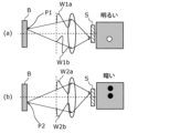
- FIG. 1 is a diagram for explaining the occurrence of brightness and darkness unevenness in imaging using sub-terahertz waves.
- FIG. 2 is a schematic diagram showing the appearance of the imaging device according to the embodiment.
- FIG. 3 is a block diagram showing the configuration of the imaging device according to the embodiment.
- FIG. 4 is a schematic diagram of the photographing device according to the embodiment viewed from above.
- FIG. 5 is a diagram illustrating an example of a circuit configuration of an image sensor according to an embodiment.
- FIG. 6 is a timing chart for explaining the operation of the image sensor shown in FIG.
- FIG. 7 is a diagram showing another example of the circuit configuration of the image sensor according to the embodiment.
- FIG. 8 is a timing chart for explaining the operation of the image sensor shown in FIG. 7.
- FIG. 7 is a diagram for explaining the operation of the image sensor shown in FIG. 7.
- FIG. 9 is a plan view showing an example of a retardation plate according to an embodiment.
- FIG. 10 is a sectional view showing an example of a retardation plate according to an embodiment.
- FIG. 11 is a schematic diagram for explaining an example of movement of an example of a retardation plate according to an embodiment.
- FIG. 12 is a plan view showing another example of the retardation plate according to the embodiment.
- FIG. 13 is a schematic diagram for explaining an example of the movement of another example of the retardation plate according to the embodiment.
- FIG. 14 is a plan view showing still another example of the retardation plate according to the embodiment.
- FIG. 15 is a schematic diagram for explaining another example of movement of the retardation plate according to the embodiment.
- FIG. 16 is a diagram illustrating an example of an image output by the detection unit according to the embodiment.
- FIG. 17 is a side view for explaining another example of the arrangement of the detection unit according to the embodiment.
- FIG. 18 is a top view for explaining yet another example of the arrangement of the detection unit according to the embodiment.
- FIG. 19 is a diagram showing an example of an image output by the detection section shown in FIG. 17.
- FIG. 20 is a diagram showing an example of an image output by the detection section shown in FIG. 18.
- FIG. 21 is a side view showing an example in which the detection section according to the embodiment is configured with a pressure sensor.
- FIG. 22 is a top view showing an example in which the detection unit according to the embodiment is configured with a distance sensor.
- FIG. 23 is a side view showing an example in which the detection unit according to the embodiment is configured with a human sensor.
- FIG. 24 is a top view showing an example in which the detection unit according to the embodiment is configured with a speed sensor.
- FIG. 25 is a schematic diagram of the photographing device according to the first modification of the embodiment viewed from above.
- FIG. 26 is a schematic diagram for explaining an example of movement of an example of a retardation plate according to Modification 1 of the embodiment.
- FIG. 27 is a schematic diagram for explaining an example of the movement of another example of the retardation plate according to Modification 1 of the embodiment.
- FIG. 28 is a schematic diagram for explaining yet another example of movement of the retardation plate according to Modification 1 of the embodiment.
- FIG. 29 is a schematic diagram of the photographing device according to the second modification of the embodiment, viewed from above.
- FIG. 30 is a schematic diagram of an imaging device according to modification 3 of the embodiment, viewed from above.
- FIG. 31 is a schematic diagram for explaining an example of movement of a light source according to modification 3 of the embodiment.
- FIG. 32 is a schematic diagram for explaining another example of the movement of the light source according to Modification 3 of the embodiment.
- FIG. 33 is a schematic diagram of an imaging device according to modification 4 of the embodiment, viewed from above.
- FIG. 34 is a diagram for explaining changes in the optical path length of sub-terahertz waves due to movement of a person.
- FIG. 35A is a schematic diagram showing an example of arrangement of pixels in a pixel array of an image sensor according to an embodiment.
- FIG. 35B is a schematic diagram showing an example of the photographing distance of the detector.
- FIG. 35A is a schematic diagram showing an example of arrangement of pixels in a pixel array of an image sensor according to an embodiment.
- FIG. 35B is a schematic diagram showing an example of the photographing distance of the
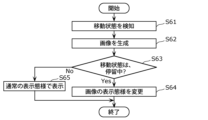
- FIG. 36 is a flowchart of operation example 1 of the photographing device according to the embodiment and each modification.
- FIG. 37 is a flowchart of operation example 2 of the photographing device according to the embodiment and each modification.
- FIG. 38 is a flowchart of operation example 3 of the photographing device according to the embodiment and each modification.
- FIG. 39 is a flowchart of operation example 4 of the photographing device according to the embodiment and each modification.
- FIG. 40 is a flowchart of operation example 5 of the photographing device according to the embodiment and each modification.
- FIG. 41 is a flowchart of operation example 6 of the photographing device according to the embodiment and each modification.
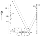
- sub-terahertz waves When photographing using sub-terahertz waves, since sub-terahertz waves have a longer wavelength than visible light, they are specularly reflected by objects to be photographed, such as the human body. Difficult to receive waves. Therefore, in order to make it easier for the image sensor to receive the reflected waves from the object to be photographed, for example, sub-terahertz waves can be diffusely reflected by a reflector and then irradiated onto the object to be photographed, so that the object can be viewed from various angles. It emits sub-terahertz waves. When such a method is used, sub-terahertz waves having different optical path lengths from a light source that emits sub-terahertz waves to the object to be imaged are incident on the object to be imaged. As a result, the sub-terahertz waves incident on the object to be photographed include components of various phases.
- FIG. 1 is a diagram for explaining the occurrence of brightness and darkness unevenness in imaging using sub-terahertz waves.
- FIG. 1 shows a case where a plate-shaped object B to be imaged that uniformly reflects sub-terahertz waves is to be imaged.
- FIG. 1A schematically shows a case where a reflected wave reflected at a certain position P1 on an object B to be photographed is photographed.
- FIG. 1B schematically shows a case where a reflected wave reflected at a position P2 different from the position P1 on the object B to be photographed is photographed.
- the reflected waves are indicated by arrows, and the reflected waves are imaged on the image sensor S.
- waveforms W1a, W1b, W2a, and W2b of reflected waves are schematically shown on arrows indicating reflected waves.
- the sub-terahertz wave incident on the object B to be photographed includes components of various phases, so the distribution of the phase of the wave reflected by the object B to be photographed with respect to the reflection angle may differ depending on the reflection position.
- the two components of the reflected wave reflected at position P1 have the same phase as shown in waveforms W1a and W1b, so the same phase components When the image is formed on the sensor S, it interferes and becomes brighter.
- the two components of the reflected wave reflected at position P2 have different phases (for example, are shifted by half a wavelength), as shown in waveforms W2a and W2b. , when components of different phases are imaged on the image sensor S, they interfere and become dark. In this way, even though the object B having uniform reflection characteristics is photographed, unevenness in brightness occurs in the obtained image.
- the present inventors have found that when imaging using sub-terahertz waves, the distribution of the phase of the reflected wave with respect to the reflection angle differs depending on the reflection position on the object to be imaged, and thus unevenness in brightness occurs in the obtained image. I found out that there is. Note that in this specification, "the distribution of the phase of the reflected wave with respect to the reflection angle” may be simply referred to as "the angular distribution of the phase of the reflected wave”.
- the present disclosure provides a photographing device that can suppress unevenness in brightness of an image that occurs regardless of the reflection characteristics of sub-terahertz waves in an object to be photographed.
- An example of an imaging device according to the present disclosure is shown below as an overview of the present disclosure.
- An imaging device is an imaging device that uses sub-terahertz waves to image an object passing through a predetermined area, and emits the sub-terahertz waves to the object.
- a radiation part a radiation part; (i) an optical system that images reflected waves of the sub-terahertz waves emitted from the radiation part by the object to be photographed; and (ii) an optical system arranged in a plane and formed by the optical system; a cumulative intensity obtained by accumulating the intensity of the reflected waves received by each of the plurality of pixels for a predetermined time, and a planar arrangement of the plurality of pixels; an image sensor that generates an image based on , and the predetermined time is ⁇ /1778 seconds or more, where the wavelength of the sub-terahertz wave is ⁇ mm.
- the object to be photographed will move more than half the wavelength of the sub-terahertz wave in a predetermined time. I will do it.
- the optical path length of the sub-terahertz wave emitted from the radiator until it is reflected by the object to be photographed and enters the image sensor is longer than the wavelength of the sub-terahertz wave before and after the movement of the object to be photographed at a given time. Change. Therefore, the image sensor can accumulate the intensity between the angular distribution patterns of the phases of two reflected waves shifted by the wavelength of the sub-terahertz wave at a predetermined time.
- the intensities of reflected waves having different phase angular distributions are effectively accumulated, and the brightness and darkness caused by the interference described above is leveled out. Therefore, in the photographing device according to this aspect, it is possible to suppress unevenness in brightness of an image that occurs regardless of the reflection characteristics of sub-terahertz waves in the object to be photographed as described above.
- a photographing device is the photographing device according to the first aspect, and includes a detection unit that detects a moving state of the object to be photographed when passing through the predetermined area; A control unit that controls the operation of the photographing device when the moving state is stationary.
- the control unit controls the operation of the photographing device. Therefore, even if the object to be photographed is stationary, by appropriately controlling the operation of the photographing device, it is possible to suppress unevenness in brightness of the image that occurs regardless of the reflection characteristics of sub-terahertz waves in the object to be photographed.
- a photographing device is a photographing device according to a second aspect, in which the control section determines the predetermined time based on the movement state, and the image sensor Then, the image is generated based on the cumulative intensity accumulated over the determined predetermined time.
- an imaging device is an imaging device that uses sub-terahertz waves to image an object to be imaged passing through a predetermined area, the imaging device transmitting the sub-terahertz waves to the object to be imaged.
- an optical system that forms an image of the reflected wave of the sub-terahertz wave emitted from the radiation unit by the object to be photographed; It includes a plurality of pixels that receive the imaged reflected waves, and the cumulative intensity obtained by accumulating the intensity of the reflected waves received by each of the plurality of pixels for a predetermined time and the planar shape of the plurality of pixels.
- a detector including an image sensor that generates an image based on the arrangement; a detection unit that detects a movement state of the object to be photographed when it passes through the predetermined area; a control unit that controls the operation, the control unit determining the predetermined time based on the movement state, and transmitting the information to the image sensor based on the cumulative intensity accumulated over the determined predetermined time. to generate the image.
- the optical path length of the sub-terahertz waves emitted from the radiation section until it is reflected by the object and enters the image sensor changes. Further, the amount of change in the optical path length during a predetermined period of time during which the image sensor accumulates the intensity of the reflected waves is determined by the moving state of the object, such as the moving speed. Furthermore, as the optical path length changes, the angular distribution of the phase of the reflected waves received by the image sensor also changes, so the angle of the phase of the reflected waves received by the image sensor at a given time varies depending on the moving state of the object to be photographed. The distribution will be affected.
- the ease with which uneven brightness occurs in images generated by a sensor is influenced by the moving state of the object to be photographed. Therefore, by the control unit determining the predetermined time based on the moving state of the object to be photographed, it is possible to appropriately control the amount of change in the optical path length in the predetermined time that affects uneven brightness of the image. Therefore, it is possible to suppress unevenness in brightness of an image that occurs regardless of the reflection characteristics of sub-terahertz waves in the object to be photographed.
- a photographing device is a photographing device according to any one of the second to fourth aspects, in which the detection unit detects that the object to be photographed is in the moving state.
- the control unit detects a moving speed when passing through the predetermined area, and determines that the moving state of the object to be photographed is in a stationary state when the moving speed is less than the predetermined speed.
- the moving state of the sub-terahertz wave emitted from the radiation section is determined based on the moving speed of the object, which is particularly susceptible to the optical path length from reflection by the object to be imaged until it enters the image sensor. can.
- the imaging device is the imaging device according to any one of the second to fifth aspects, and the control unit controls the control unit when the moving state is at rest. Then, the detector is caused to stop generating the image.
- an image will not be generated in a case where the uneven brightness of the image becomes large regardless of the reflection characteristics of sub-terahertz waves in the object to be photographed. Therefore, for example, when detecting a dangerous object using an image, an image that would reduce the detection accuracy of the dangerous object is not output, and false detection can be suppressed.
- a photographing device is a photographing device according to any one of the second to fifth aspects, and includes a display unit that displays the image, and the control unit , when the moving state is stationary, causing the display unit to stop displaying the image, or superimposing another image on the image;
- a photographing device is a photographing device according to any one of the second to seventh aspects, and includes an alarm that issues a warning, and the control unit: When the moving state is at rest, the alarm is caused to issue the warning.
- a photographing device is a photographing device according to any one of the second to fifth aspects, and is provided during an exposure period when the image sensor generates the image. further comprising a phase modulation unit that changes the phase angle distribution of the reflected wave received by the image sensor, and the control unit controls the phase modulation unit to change the phase angle distribution of the reflected wave when the moving state is stationary. Change the distribution.
- the phase modulation section allows the image sensor to receive the image. It is possible to change the angular distribution of the phase of the reflected wave. Therefore, it is possible to suppress unevenness in brightness of an image that occurs regardless of the reflection characteristics of sub-terahertz waves in the object to be photographed.
- a photographing device is a photographing device according to a ninth aspect, in which the radiation section includes a light source that emits the sub-terahertz wave, and a sub-terahertz wave emitted from the light source. a reflector that diffusely reflects the terahertz wave to radiate the sub-terahertz wave to the object to be photographed, and the phase modulator is disposed between the light source and the reflector, and a retardation plate drive unit that moves the retardation plate under predetermined conditions.
- the phase of the sub-terahertz wave irradiated onto the object to be photographed changes, so it is possible to effectively change the angular distribution of the phase of the reflected wave received by the image sensor at a predetermined time.
- diffuse reflection refers to sub-terahertz waves incident on a reflector at a single incident angle from a macro perspective, due to the structure of the uneven surface having multiple microscopic unevenness. It means that it is reflected at the reflection angle.
- a photographing device is a photographing device according to a ninth aspect, in which the phase modulation section transmits light of the reflected wave between the predetermined region and the image sensor.
- the vehicle includes a retardation plate disposed on a road and changing the phase of the transmitted reflected wave, and a retardation plate drive unit that moves the retardation plate under predetermined conditions.
- the phase of the reflected wave from the object to be photographed that enters the image sensor changes, so it is possible to effectively change the angular distribution of the phase of the sub-terahertz wave received by the image sensor at a predetermined time.
- a photographing device is a photographing device according to a ninth aspect, in which the phase modulation section is at least a part of the optical system, and the optical system is configured to a mirror system that forms an image on the image sensor by reflecting the reflected wave; the mirror system includes a plurality of mirrors, and each of the plurality of mirrors is configured to form an image on the image sensor during an exposure period of the image sensor. The phase of the reflected wave is changed.
- phase modulation section and the detector can be integrated, and the angular distribution of the phase of the reflected wave received by the image sensor can be changed.
- a photographing device is a photographing device according to a ninth aspect, in which the radiation section includes a light source that emits the sub-terahertz wave, and a sub-terahertz wave emitted from the light source.
- a reflector that diffusely reflects the terahertz waves to radiate the sub-terahertz waves to the object to be photographed, and the phase modulator moves the light source under predetermined conditions to adjust the phase angle. It includes a light source driver that changes the distribution.
- the optical path length changes as the light source moves, so it is possible to effectively change the angular distribution of the phase of the reflected waves received by the image sensor at a predetermined time.
- a photographing device is a photographing device according to a ninth aspect, in which the radiation section includes a light source that emits the sub-terahertz wave, and a sub-terahertz wave emitted from the light source. a reflector that radiates the sub-terahertz wave to the object to be photographed by diffusely reflecting the terahertz wave, and the phase modulator moves the reflector under predetermined conditions to change the phase of the object. It includes a reflector drive unit that changes the angular distribution.
- the optical path length changes as the reflecting plate moves, so it is possible to effectively change the angular distribution of the phase of the reflected waves received by the image sensor at a predetermined time.
- an imaging device is an imaging device according to any one of the ninth to fourteenth aspects, in which the phase modulation section
- the image sensor includes a conveying unit that moves the object to be photographed by more than half the wavelength of the sub-terahertz wave during the exposure period of the image sensor to change the angular distribution of the phase.
- an imaging device is an imaging device according to any one of the first to fifteenth aspects, in which the predetermined time is the shortest imaging distance in the detector. is L/27800 seconds or less, where L mm is L/27800 seconds or less.
- the shift in the position of the pixel where the reflected wave from the object is incident due to the movement of the object during a predetermined period of time is likely to be less than half a pixel length, thereby suppressing blur in the generated image.
- a photographing device is a photographing device according to any one of the first to sixteenth aspects, in which the predetermined time is the exposure of the image sensor in one frame. It is the length of the period.
- the image sensor can generate an image in one frame of exposure period, so the time to generate one image can be shortened.
- a photographing device is a photographing device according to any one of the first to seventeenth aspects, and the predetermined time is ⁇ /254 seconds or more.
- the optical path length changes further before and after the movement of the object to be photographed during a predetermined period of time. Therefore, it is possible to further suppress unevenness in brightness of the image that occurs regardless of the reflection characteristics of sub-terahertz waves in the object to be photographed.
- an imaging device is an imaging device according to any one of the first to eighteenth aspects, wherein the frequency of the sub-terahertz wave is 0.05 THz or more and 2 THz or less.
- the wavelength of the sub-terahertz wave is 0.15 mm or more and 6 mm or less.
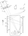
- FIG. 2 is a schematic diagram showing the appearance of the photographing device 10 according to the present embodiment.
- components other than the reflection plate 22 are omitted.
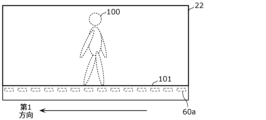
- the imaging device 10 irradiates the person 100 with sub-terahertz waves, for example, when the person 100 passes through the imaging space 102 on the passage 101 sandwiched between the reflectors 22.
- the photographing space 102 is, for example, a space above the passageway 101 that is sandwiched between the reflectors 22 .
- the photographing device 10 photographs, for example, a dangerous object such as a knife that the person 100 conceals under his or her clothes.
- the person 100 and a dangerous object such as a knife that the person 100 conceals under their clothes are examples of objects to be photographed.
- the photographing space 102 is an example of a predetermined space.
- the imaging space 102 is not particularly limited as long as it is a space that is irradiated with sub-terahertz waves and can photograph objects within the imaging space 102 using sub-terahertz waves.
- sub-terahertz waves refer to electromagnetic waves that have a frequency of 0.05 THz or more and 2 THz or less, and a wavelength of 0.15 mm or more and 6 mm or less.
- the sub-terahertz wave in this specification may be an electromagnetic wave having a frequency of 0.08 THz or more and 1 THz or less, and a wavelength of 0.3 mm or more and 3.75 mm or less.
- FIG. 3 is a block diagram showing the configuration of the imaging device 10 according to this embodiment.
- FIG. 4 is a schematic diagram of the photographing device 10 according to the present embodiment viewed from above.
- FIG. 4 shows a person 100 passing through the imaging space 102.
- an example of the course of the sub-terahertz wave emitted from the light source 21 is shown by an arrow.
- the photographing device 10 includes a radiation section 20, a detector 30, a control section 40, a phase modulation section 50, a detection section 60, an alarm 70, a transport section 80, an image processing section 90, and a display section 95. and.
- the radiation section 20 emits sub-terahertz waves to the person 100.
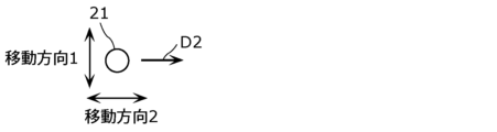
- the radiation section 20 includes, for example, a light source 21 that emits sub-terahertz waves, and a reflecting plate 22 that diffusely reflects the sub-terahertz waves emitted from the light source 21.
- the radiation section 20 includes two light sources 21 and two reflection plates 22.
- the light source 21 is a light source that emits sub-terahertz waves to the reflecting plate 22. Specifically, the light source 21 emits sub-terahertz waves to the surface 22a of the reflection plate 22. Further, as shown in FIG. 4, the light source 21 transmits the sub-terahertz waves to the reflecting plate 22 so that at least a part of the sub-terahertz waves emitted by the light source 21 is diffusely reflected by the reflecting plate 22 at least once. Inject. Further, a part of the sub-terahertz waves emitted by the light source 21 may be directly incident on the person 100.
- the light source 21 emits, for example, sub-terahertz waves having a substantially single wavelength.
- the light source 21 is, for example, a light source that emits coherent sub-terahertz waves.
- one of the two light sources 21 emits sub-terahertz waves toward one of the two reflectors 22 .
- the other light source 21 of the two light sources 21 emits sub-terahertz waves toward the other of the two reflectors 22 .
- One light source 21 is located, for example, on the surface 22a side of one reflecting plate 22 and on the first direction side of one reflecting plate 22.
- the first direction is the direction in which the passage 101 extends in the photographing device 10 and the person 100 advances. Further, the first direction is, for example, parallel to the direction in which the reflecting plate 22 extends when viewed from above (in other words, perpendicular to the thickness direction of the reflecting plate 22).
- the other light source 21 is located, for example, on the surface 22a side of the other reflecting plate 22 and on the first direction side of the other reflecting plate 22.
- the light source 21 and the reflection plate 22 are separated from each other. Further, the light source 21 is placed closer to the reflector 22 than the detector 30, for example.
- the number of light sources 21 included in the radiation section 20 is not limited to two, and may be one, or three or more.
- the light source 21 is, for example, a point light source that emits sub-terahertz waves around the light source 21. Further, the light source 21 may be a line light source that extends along the end of the reflection plate 22 in the first direction and emits sub-terahertz waves.
- the light source 21 is realized by, for example, a light source including a known sub-terahertz wave generating element.
- the reflective plate 22 covers the space above the passage 101 through which the person 100 passes, specifically the photographing space 102, from at least one of both sides of the passage 101.
- covering the passage 101 from at least one of both sides means covering it from both sides when the passage 101 is viewed from above, that is, from at least one of two directions perpendicular to the direction in which the passage 101 extends. It means that.
- the reflecting plate 22 sandwiches the photographing space 102 on the passage 101 through which the person 100 passes from both sides of the passage 101 . That is, the reflector 22 covers the photographing space 102 from both sides of the passage 101.
- the photographing space 102 is, for example, a space above the passageway 101 that is sandwiched between the inner surfaces 22a of the two reflecting plates 22.
- the two reflecting plates 22 are erected from the floor surface on both sides of the passageway 101 and face each other. That is, the two reflecting plates 22 are arranged so as to sandwich the passage 101 when viewed from above. Further, in the illustrated example, the two reflecting plates 22 are arranged so as to be parallel to each other. Furthermore, in the illustrated example, the two reflecting plates 22 are each erected perpendicularly to the floor surface on which the passage 101 is provided.
- the photographing device 10 only needs to include at least one reflecting plate 22, and may include only one of the two reflecting plates 22, for example. Further, for example, the photographing device 10 may further include a reflector other than the two illustrated reflectors 22, for example, a reflector located above the two reflectors 22. Further, the reflecting plate 22 may be a tunnel-shaped reflecting plate that stands up from the floor surface.
- the two reflecting plates 22 are each plate-shaped.
- the two reflecting plates 22 each have a surface 22a that is a front surface when viewed from the thickness direction of the reflecting plate 22.
- the two reflecting plates 22 are arranged such that one surface 22a of the two reflecting plates 22 and the other surface 22a of the two reflecting plates 22 face each other.
- the surface 22a is the surface of the reflecting plate 22 on the imaging space 102 side.
- the shape of each of the reflecting plates 22 in plan view is not particularly limited, but is, for example, rectangular.
- the reflecting plate 22 diffusely reflects the sub-terahertz waves emitted from the light source 21. Specifically, the reflection plate 22 diffusely reflects the sub-terahertz waves incident from the imaging space 102 side on the surface 22a. Therefore, the surface 22a is a sub-terahertz wave radiation surface, and the reflection plate 22 functions as a surface light source.
- the surface 22a is an uneven surface that diffusely reflects sub-terahertz waves.
- the average length RSm of the roughness curve elements is equal to or longer than the wavelength of the sub-terahertz wave emitted from the light source 21.
- the average length RSm of the roughness curve elements is 0.15 mm or more, and may be 0.3 mm or more.
- the reflecting plate 22 including the surface 22a is made of a conductive member such as a metal or a conductive oxide.
- the reflective plate 22 may include a protective member that covers the surface 22a.
- the protection member is made of, for example, a material such as resin that transmits sub-terahertz waves.
- the sub-terahertz waves emitted from the light source 21 are diffusely reflected one or more times by at least one of the two reflecting plates 22, and are irradiated onto the person 100.
- the sub-terahertz waves that have entered the imaging space 102 can be easily stopped, and the sub-terahertz waves can be viewed from various angles toward the person 100. is irradiated.
- the sub-terahertz waves emitted from the light source 21 are diffusely reflected one or more times by the reflector 22 and radiated to the person 100, the sub-terahertz waves emitted from the light source 21 are emitted until the person 100 is irradiated.
- a distribution occurs in the optical path length.
- the phase of the sub-terahertz wave incident on the person 100 is distributed depending on the distribution of the optical path length, so that the wave reflected by the person 100 also has a phase angular distribution. Therefore, when such a radiation section 20 is used, as explained using FIG. 1, unevenness in brightness tends to occur in an image of reflected waves. In the photographing device 10 according to the present embodiment, such unevenness in brightness of an image can be suppressed.
- the detector 30 generates an image based on the waves reflected by the person 100 of the sub-terahertz waves emitted from the radiation section 20 . Generating an image is also referred to as "photographing.” That is, the detector 30 of the photographing device 10 photographs the person 100 present in the photographing space 102. The detector 30 outputs the generated image to the image processing section 90.
- Detector 30 includes an image sensor 31 and an optical system 32. The detector 30 is placed at a position where it can receive the waves reflected by the person 100. The detector 30 is located on the first direction side of the reflecting plate 22, for example.
- the image sensor 31 receives the sub-terahertz wave reflected by the person 100, which is emitted from the light source 21 and then diffusely reflected by the reflection plate 22.
- the image sensor 31 detects the intensity of the received reflected wave and generates an image based on the detected intensity.
- the image sensor 31 is arranged in a plane and includes a plurality of pixels that receive reflected waves imaged by the optical system 32.
- the image sensor 31 generates an image based on a signal corresponding to the cumulative intensity obtained by accumulating the intensity of reflected waves received by each of the plurality of pixels for a predetermined period of time, and the planar arrangement of the plurality of pixels.
- the predetermined time is, for example, the length of the exposure period in one frame, but may be the total length of the exposure periods in a plurality of frames.
- the image sensor 31 converts, for example, an image of a reflected wave emitted from the person 100 into an electrical signal according to the cumulative intensity. The image sensor 31 then generates an image based on the converted electrical signal. The image generated by the image sensor 31 is output to the image processing section 90. Further, the image sensor 31 includes a control circuit 31a that controls each circuit of the image sensor 31. The detailed configuration of the image sensor 31 will be described later.
- the optical system 32 forms an image of the sub-terahertz wave emitted from the radiation section 20 reflected by the person 100 on the image sensor 31 .
- the optical system 32 includes, for example, at least one lens or mirror.
- the image sensor 31 can be set to have a longer predetermined time for accumulating the intensity of received reflected waves, for example, than a conventional image sensor that generates images of sub-terahertz waves.
- the predetermined time may be, for example, ⁇ /1778 seconds or more, and may be ⁇ /254 seconds or more, where ⁇ mm is the wavelength of the subterahertz wave emitted by the radiation section 20.
- the predetermined time may be ⁇ /10 seconds or less, or may be ⁇ /30 seconds or less.
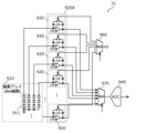
- FIG. 5 is a diagram showing an example of the circuit configuration of the image sensor 31 according to the present embodiment.
- the image sensor 31 includes a pixel array 910, an integrating circuit 920, a multiplexer 930, an analog-to-digital converter 940, and a combining circuit 950.
- the pixel array 910 includes a plurality of pixels 911 arranged in a plane.
- the pixel array 910 forms a receiving surface on which reflected waves are imaged.
- the plurality of pixels 911 are arranged in an array of 8 rows and 4 columns.
- four pixels 911 out of 32 pixels 911 are shown as representatives.
- the number of pixels 911 is not particularly limited.
- Each of the plurality of pixels 911 includes a conversion element such as a diode that converts the received sub-terahertz wave into an electric charge.
- Each of the plurality of pixels 911 generates an amount of charge depending on the intensity of the received sub-terahertz wave (specifically, the wave reflected by the person 100).
- the configuration of the plurality of pixels 911 is not limited to a configuration including a diode, and is not particularly limited as long as it includes a conversion element that can convert the received sub-terahertz wave into an electrical signal.
- the integration circuit 920 is a circuit that integrates the input from the pixel 911 during the exposure period. Integrating circuit 920 is connected to each of the plurality of pixels 911 via multiplexer 930. The charge (voltage) generated in the pixel 911 is input to the integrating circuit 920 .
- the integrating circuit 920 includes an operational amplifier 921, a capacitive element 922, and a switch 923.
- the inverting input terminal of the operational amplifier 921 is connected to the plurality of pixels 911 via a multiplexer 930.
- a non-inverting input terminal of operational amplifier 921 is connected to reference voltage Vref.
- the output of operational amplifier 921 is connected to analog-to-digital converter 940.
- One end of the capacitive element 922 is connected between the inverting input terminal of the operational amplifier 921 and the multiplexer 930.
- the other end of capacitive element 922 is connected between the output of operational amplifier 921 and analog-to-digital converter 940.
- switch 923 One end of the switch 923 is connected between the inverting input terminal of the operational amplifier 921 and the multiplexer 930. The other end of switch 923 is connected between the output of operational amplifier 921 and analog-to-digital converter 940 via a resistor. Further, the switch 923 is connected in parallel with the capacitive element 922.
- the charge from the pixel 911 is accumulated in the capacitive element 922 (that is, the voltage is integrated) while the switch 923 is off, and the operational amplifier 921 outputs a voltage according to the accumulated charge. Furthermore, when the switch 923 is turned on, the charge accumulated in the capacitive element 922 is discharged.
- the multiplexer 930 selects the output of one pixel 911 from among the outputs of the plurality of pixels 911 and outputs it to the integrating circuit 920.
- the analog-to-digital converter 940 performs AD (Analog to Digital) conversion on the output from the integrating circuit 920 and outputs it to the subsequent stage circuit. Further, the analog-to-digital converter 940 outputs a signal that synchronizes the on/off operation of the switch 923 and the selection of the pixel 911 to be read.
- AD Analog to Digital
- the synthesis circuit 950 synthesizes the signals of each pixel 911 obtained in a plurality of frames.
- the synthesis circuit 950 receives, for example, a digital signal (pixel value) AD-converted by the analog-to-digital converter 940, stores it in a memory, etc., and integrates or averages the signals of each pixel 911 in a plurality of frames.
- the synthesis circuit 950 is provided after the analog-to-digital converter 940, but it may be provided before the analog-to-digital converter 940.
- the synthesis circuit 950 may be a circuit that includes a multiplexer, a capacitive element, and the like, and holds and accumulates the analog signal (voltage) of each pixel 911 over a plurality of frames before AD conversion. Then, the analog signal accumulated by the synthesis circuit 950 may be AD converted.
- the operation of at least one of the pixel array 910, the integrating circuit 920, the multiplexer 930, the analog-to-digital converter 940, and the combining circuit 950 is controlled by, for example, the above-mentioned control circuit 31a. Ru. Further, the control circuit 31a may have a function of modulating a clock that determines the exposure period (frame length) of the plurality of pixels 911.
- FIG. 6 is a timing chart for explaining the operation of the image sensor 31 shown in FIG.
- the signal readout operation timings of four pixels 911 among the plurality of pixels 911 are representatively shown in rows labeled pixel 1 to pixel 4.
- a reset operation is performed during the reset period before integrating the signal of pixel 1.
- the switch 923 is turned on to discharge the charge in the capacitive element 922, and the input of the pixel 1 is selected by the multiplexer 930, thereby performing a reset operation.
- the switch 923 is turned off, thereby starting the exposure period of the pixel 1.
- the charge from the pixel 1 is accumulated in the capacitive element 922, and the input (voltage) of the pixel 1 is integrated. In other words, the intensity of the waves reflected by the person 100 is accumulated.
- the integrated voltage is read out from the integration circuit 920. Specifically, the integrated voltage is input to an analog-to-digital converter 940, subjected to AD conversion, and output to a subsequent circuit. As a result, a digital signal (pixel value) corresponding to the intensity of the reflected wave received by the pixel 1, which is integrated during the exposure period of the pixel 1, is output.
- the reset period of pixel 2 starts, and the same operations as pixel 1 from reset to signal readout are performed in pixel 2 as well.
- one frame period Tf ends, and the pixel value of each of the plurality of pixels 911 is output.
- one integrating circuit 920 is connected to 32 pixels 911. Therefore, as can be seen from FIG. 6, during the exposure period of one pixel 911, it is not possible to set an exposure period for another pixel 911. As a result, the exposure period of one pixel 911 becomes Tf/32 or less. Therefore, when the image sensor 31 does not include the combining circuit 950, an image is generated based on a signal corresponding to the cumulative intensity of reflected waves accumulated over a very short period of time. On the other hand, since the image sensor 31 includes the synthesis circuit 950, it is possible to generate an image in which signals from each exposure period of a plurality of frames are synthesized, so that the predetermined time for accumulating the intensity can be lengthened. . In other words, the predetermined time for accumulating the intensity is the length of the exposure period multiplied by the number of frames in which signals are combined.
- FIG. 7 is a diagram showing another example of the circuit configuration of the image sensor 31 according to the present embodiment.
- description of the same components as in FIG. 5 may be omitted or simplified.
- the image sensor 31 includes a pixel array 910, an integrating circuit group 920A, an analog-to-digital converter 940, a multiplexer 960, and a multiplexer 970.
- the integrating circuit group 920A includes a plurality of integrating circuits 920.
- FIG. 7 shows a plurality of integration circuits 920 arranged vertically in the integration circuit group 920A, the arrangement of the plurality of integration circuits 920 is not particularly limited.
- the plurality of integrating circuits 920 may not be arranged in a row, but may be arranged discretely.
- the plurality of integrating circuits 920 are connected one-to-one to the plurality of pixels 911. That is, one integrating circuit 920 is connected to one pixel 911. Therefore, in this example, there is no need for the multiplexer 930 between the pixel 911 and the integrating circuit 920 as in the example shown in FIG. Note that the plurality of integrating circuits 920 may not be connected one-to-one to the plurality of pixels 911, and one integrating circuit 920 may be connected to two or more pixels 911 via a multiplexer.
- the multiplexer 960 is connected to the control line of each switch 923 of the plurality of integrating circuits 920. Multiplexer 960 selects one integrating circuit 920 from among the plurality of integrating circuits 920 based on the selection signal and outputs a signal for controlling on/off of switch 923 .
- the multiplexer 970 is connected to each output of the plurality of integrating circuits 920 (output terminal of the operational amplifier 921). Based on the selection signal, multiplexer 970 selects the output of one integrating circuit 920 from among the outputs of multiple integrating circuits 920 and outputs it to analog-to-digital converter 940.
- the operation of at least one of the pixel array 910, the integrating circuit group 920A, the analog-to-digital converter 940, the multiplexer 960, and the multiplexer 970 is controlled by, for example, the above-mentioned control circuit 31a. Ru. Further, the control circuit 31a may have a function of modulating a clock that determines the exposure period (frame length) of the plurality of pixels 911.
- FIG. 8 is a timing chart for explaining the operation of the image sensor 31 shown in FIG. 7.
- the signal readout operation timings of four representative pixels 911 among the plurality of pixels 911 are shown in rows labeled from pixel 1 to pixel 4.
- a reset operation is first performed during the reset period before integrating the signal of pixel 1.
- the selection of the multiplexer 960 turns on the switch 923 of the integrating circuit 920 corresponding to pixel 1.
- the switch 923 of the integrating circuit 920 corresponding to pixel 1 is turned off, thereby starting the exposure period of pixel 1.
- a reset operation of pixel 2 is performed during the reset period, and further the exposure period of pixel 2 starts.
- the switch 923 of the integrating circuit 920 corresponding to pixel 2 is controlled by the selection of the multiplexer 960. In this way, the exposure period of pixel 1 and the reset period and exposure period of pixel 2 overlap.
- the multiplexer 970 selects the integrating circuit 920 corresponding to pixel 1, and the integrated voltage is applied to pixel 1. It is read out from the corresponding integration circuit 920. Specifically, the integrated voltage is input to an analog-to-digital converter 940, subjected to AD conversion, and output to a subsequent circuit. As a result, a digital signal (pixel value) corresponding to the intensity of the reflected wave received by the pixel 1, which is integrated during the exposure period of the pixel 1, is output.
- the readout period of pixel 1 overlaps with the exposure period of pixels 911 other than pixel 1.
- the same readout operation as for pixel 1 is sequentially performed for a plurality of pixels 911 other than pixel 1.
- the pixel value of each of the plurality of pixels 911 is obtained, and a signal corresponding to the cumulative intensity obtained by accumulating the intensity of the reflected waves received by each of the plurality of pixels 911 for a predetermined time, and a signal corresponding to the cumulative intensity of the reflected waves received by each of the plurality of pixels 911 and An image is generated based on the planar arrangement.
- the image sensor 31 includes a plurality of integrating circuits 920, so that the exposure periods of the plurality of pixels 911 can be overlapped. Therefore, in the plurality of pixels 911, the proportion of the exposure period in the frame period Tf can be increased.
- the predetermined time for the image sensor 31 to accumulate the intensity of the reflected waves is the length of the exposure period in one frame, and compared to the image sensor 31 in the example shown in FIG. Since the example image sensor 31 can secure a long exposure period, it is possible to lengthen the predetermined time for accumulating the intensity in one frame period Tf. Therefore, the time to generate an image can be shortened. Furthermore, since the intensity of the reflected waves is accumulated over consecutive periods, blurring of the obtained image can be suppressed.
- the image sensor 31 shown in FIG. 7 may further include the synthesis circuit 950 shown in FIG. 5.
- control unit 40 is a control device that controls operations in the photographing device 10.
- the control unit 40 controls at least one of the radiation unit 20 , the detector 30 , the phase modulation unit 50 , the detection unit 60 , the alarm 70 , the transport unit 80 , and the display unit 95 to control the operation of the imaging device 10 .
- Control behavior Further, the control unit 40 controls the operation of the photographing device 10 based on the movement state of the person 100 detected by the detection unit 60 when passing through the photographing space 102, for example. Details of the operation control by the control unit 40 will be described later.
- the control unit 40 includes, for example, a processor and a memory, and is realized by the processor executing a program stored in the memory.
- the phase modulation unit 50 changes the angular distribution of the phase of the reflected waves received by the image sensor 31 during an exposure period when the image sensor 31 generates an image.
- the phase modulation section 50 changes the phase of at least a part of the components of the reflected wave after the sub-terahertz wave emitted from the radiation section 20 is reflected by the person 100.
- the phase modulation unit 50 may change the angular distribution of the phase of the reflected wave received by the image sensor 31 by changing the phase of the sub-terahertz wave radiated to the person 100.
- An example in which the phase modulation section 50 changes the phase of the sub-terahertz wave radiated to the person 100 will be described later.
- the phase modulation unit 50 operates, for example, under the control of the control unit 40, but may operate at all times while the imaging device 10 is capturing an image.
- the phase modulation section 50 includes a phase difference plate 51 and a drive section 52.
- the drive unit 52 is an example of a retardation plate drive unit.
- the retardation plate 51 is a plate-shaped member that is transparent to sub-terahertz waves and changes the phase of the transmitted sub-terahertz waves.
- the amount of change in the phase of the transmitted sub-terahertz wave varies depending on the position where the sub-terahertz wave is transmitted through the retardation plate 51.
- the sub-terahertz waves that pass through the retardation plate 51 are waves reflected by the person 100 of the sub-terahertz waves emitted from the radiation section 20 .
- the retardation plate 51 is moved by the driving unit 52, the amount of change in the phase of the sub-terahertz wave passing through the retardation plate 51 changes depending on the position and time.
- the retardation plate 51 transmits, for example, 50% or more of the sub-terahertz waves incident from the thickness direction of the retardation plate 51.
- the retardation plate 51 may transmit 80% or more, or 90% or more, of the sub-terahertz waves incident from the thickness direction of the retardation plate 51.
- the retardation plate 51 is placed between the imaging space 102 and the image sensor 31 on the optical path of the reflected wave from the person 100 that enters the image sensor 31.
- the retardation plate 51 is arranged between the imaging space 102 and the optical system 32, but it may be arranged between the optical system 32 and the image sensor 31.
- a dielectric material such as a resin material that is transparent to sub-terahertz waves is used.
- the resin material include polycarbonate resin, acrylic resin, epoxy resin, silicone resin, polystyrene resin, polyethylene resin, polypropylene resin, and fluorine resin.
- the driving unit 52 is a driving device that changes the angular distribution of the phase of the reflected wave received by the image sensor 31 by moving the retardation plate 51 under predetermined conditions. For example, the driving unit 52 moves the retardation plate 51 so that the amount of change in the phase of the sub-terahertz wave transmitted through the retardation plate 51 changes during the exposure period of the image sensor 31.
- the drive unit 52 includes, for example, a drive device such as a motor and an actuator, and power transmission members such as a belt, a gear, a pulley, and a connecting shaft for transmitting power to the retardation plate 51.
- FIG. 9 is a plan view showing an example of the retardation plate 51 according to the present embodiment.
- FIG. 10 is a cross-sectional view showing an example of the retardation plate 51 according to this embodiment.
- FIG. 10 shows a cross section taken along line XX in FIG.
- FIG. 11 is a schematic diagram for explaining an example of the movement of the retardation plate 51 according to the present embodiment. Note that in FIGS. 9 and 10, in order to distinguish between the first region 51a and the second region 51b, different patterns are attached to each region. This also applies to FIGS. 12 and 14, which will be described later.
- the retardation plate 51 includes a first region 51a and a second region 51b.
- the first region 51a and the second region 51b each have sub-terahertz wave transparency.
- the first region 51a and the second region 51b differ in the amount of change in the phase of the sub-terahertz wave when the sub-terahertz wave is transmitted therethrough.
- the first region 51a and the second region 51b have different thicknesses, the amount of change in the phase of the sub-terahertz wave when the sub-terahertz wave is transmitted is different.
- the sub-terahertz waves that pass through the first region 51a and the second region 51b are waves reflected by the person 100.
- the thickness of the first region 51a is smaller than the thickness of the second region 51b, but it may be larger.
- the amount of change in the phase of the sub-terahertz wave can be set to a desired amount.
- the amount of change in the phase of the sub-terahertz wave when the sub-terahertz wave is transmitted may be different.
- the first region 51a and the second region 51b may have the same thickness.
- the difference in the amount of change in the phase of the sub-terahertz wave when the sub-terahertz wave is transmitted between the first region 51a and the second region 51b is, for example, 1/4 or more or more than 3/3 of the wavelength of the sub-terahertz wave used in the imaging device 10. 4 or less (that is, 90° or more and 270° or less), and may be 1/2 (that is, 180°) of the wavelength of the subterahertz wave used in the imaging device 10.
- the retardation plate 51 may include yet another region in which the amount of change in the phase of the sub-terahertz wave when the sub-terahertz wave is transmitted is different from the first region 51a and the second region 51b.
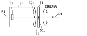
- the retardation plate 51 is moved, for example, by the drive unit 52, through the center 32c of the optical system 32, at an inclination angle with respect to a direction parallel to the incident direction D1 of the reflected wave to the optical system 32. is rotated around a rotation axis R1 of ⁇ 10° or more and 10° or less.
- the rotation axis R1 is a virtual axis and does not necessarily mean that a substantial shaft body exists. The same applies to the rotating shaft described below.
- the incident direction D1 of the reflected wave to the optical system 32 is, for example, the direction connecting the focal point of the optical system 32 and the center 32c of the optical system 32 (in other words, the optical axis direction of the optical system 32).
- the retardation plate 51 is moved by using a motor equipped with a pulley as the drive unit 52 and connecting the pulley and the retardation plate 51 with a belt.
- the phase difference plate 51 rotates one revolution or more during the exposure period of the image sensor 31.
- the rotational speed of the retardation plate 51 is not particularly limited as long as it can be rotated by the drive unit 52.
- the rotation axis R1 is, for example, parallel to the thickness direction of the retardation plate 51, and passes through the center 51c of the retardation plate 51 in plan view.
- the retardation plate 51 by arranging the retardation plate 51 so as to rotate about the rotation axis R1 passing through the center 32c of the optical system 32, the retardation plate 51 to be driven can be arranged compactly.
- the rotation axis R1 does not need to pass through the center 51c of the retardation plate 51.
- the rotation axis R1 may pass through a position other than the center 32c of the optical system 32.
- the rotation axis R1 does not need to be parallel to the thickness direction of the retardation plate 51, and may be inclined with respect to the thickness direction (for example, inclined at an inclination angle of ⁇ 10° or more and 10° or less).
- the retardation plate 51 is, for example, circular in plan view, but the shape of the retardation plate 51 in plan view is not particularly limited.
- a plan view means a case where the retardation plate 51 is viewed along the thickness direction of the retardation plate 51.
- the first region 51a and the second region 51b are arranged along the rotation direction of the retardation plate 51 in a plan view.
- the first region 51a and the second region 51b each have, for example, a sector shape with the center 51c of the retardation plate 51 as the apex, and the first region 51a and the second region 51b are arranged along the arc direction. I'm here. Note that in the example shown in FIG.
- the retardation plate 51 includes one first region 51a and one second region 51b, but it does not include a plurality of first regions 51a and a plurality of second regions 51b. It's okay to stay.
- the first regions 51a and the second regions 51b are arranged alternately along the rotation direction of the retardation plate 51, for example.
- the area of the first region 51a is larger than the area of the second region 51b.
- the area of each of the first region 51a and the second region 51b is the total area of the plurality of regions.
- the first region 51a includes a symmetrical region 51a1 in which the first region 51a exists in a point-symmetrical position across the rotation axis R1, and a second region 51b in a point-symmetrical position across the rotational axis R1. an asymmetric region 51a2.
- the components of the reflected wave passing through two certain points pass through the asymmetric region 51a2 and the second region 51b due to the rotation of the retardation plate 51 at a different time point than at a certain point.
- the area of the asymmetric region 51a2 is, for example, 1/8 or more and 3/8 or less of the area of the retardation plate 51, and may be 1/4.
- the area of the symmetrical region 51a1 is, for example, 3/8 or more and 5/8 or less of the area of the retardation plate 51, and may be 1/2.
- the retardation plate 51 is not particularly limited as long as it is a member that can change the phase of the sub-terahertz wave that passes therethrough.
- FIG. 12 is a plan view showing another example of the retardation plate 51 according to this embodiment.
- FIG. 13 is a schematic diagram for explaining another example of the movement of the retardation plate 51 according to the present embodiment.
- the retardation plate 51 includes a plurality of first regions 51a and a plurality of second regions 51b. Note that in this example, the retardation plate 51 may include only one first region 51a and one second region 51b.
- the retardation plate 51 is moved, for example, by the driving unit 52, so that the wave does not pass through the optical system 32 and is tilted at an angle of - It is rotated about a rotation axis R2 of 10 degrees or more and 10 degrees or less as a rotation center.
- the phase difference plate 51 rotates one revolution or more during the exposure period of the image sensor 31.
- the rotational speed of the retardation plate 51 is not particularly limited as long as it can be rotated by the drive unit 52.
- the rotation axis R2 is, for example, parallel to the thickness direction of the retardation plate 51, and passes through the center 51c of the retardation plate 51 in plan view.
- the retardation plate 51 can be rotated simply by attaching the shaft body to the retardation plate 51. Therefore, the structure can be simplified.
- the rotation axis R2 does not need to pass through the center 51c of the retardation plate 51.
- the rotation axis R2 does not need to be parallel to the thickness direction of the retardation plate 51, and may be inclined with respect to the thickness direction (for example, inclined at an inclination angle of ⁇ 10° or more and 10° or less).
- the retardation plate 51 is, for example, circular in plan view, but the shape of the retardation plate 51 in plan view is not particularly limited.
- the first regions 51a and the second regions 51b are arranged alternately along the rotation direction of the retardation plate 51.
- the plurality of first regions 51a and the plurality of second regions 51b each have, for example, a fan shape with the center 51c of the retardation plate 51 as the apex, and the first regions 51a and the second regions 51b are arranged in the arc direction. are arranged alternately along the In plan view, the areas of the plurality of first regions 51a and the plurality of second regions 51b are, for example, equal to each other. Note that, in plan view, at least one area of each of the plurality of first regions 51a and the plurality of second regions 51b may be different.
- FIG. 14 is a plan view showing still another example of the retardation plate 51 according to this embodiment.
- FIG. 15 is a schematic diagram for explaining yet another example of the movement of the retardation plate 51 according to the present embodiment.
- the retardation plate 51 includes a plurality of first regions 51a and a plurality of second regions 51b.
- the first region 51a and the second region 51b are arranged along a predetermined direction.
- the number of at least one of the first region 51a and the second region 51b included in the retardation plate 51 may be one.
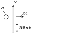
- the retardation plate 51 is driven, for example, by the drive unit 52 in a direction perpendicular to the incident direction D1 of the reflected wave to the optical system 32 and in a direction perpendicular to the thickness direction of the retardation plate 51.
- the predetermined frequency is, for example, a frequency whose cycle is equal to or less than the exposure period of the image sensor 31.
- the upper limit of the predetermined frequency is not particularly limited as long as the frequency can be reciprocated by the drive unit 52.
- the retardation plate 51 has an oval shape having a long axis and a short axis in a plan view, but the shape of the retardation plate 51 in a plan view is not particularly limited. .
- the shape of the retardation plate 51 in plan view may be an ellipse or a rectangle having a long axis and a short axis. Further, the shape of the retardation plate 51 in plan view may be circular, square, polygonal, or the like.
- the first regions 51a and the second regions 51b are arranged alternately along the moving direction of the retardation plate 51.
- the plurality of first regions 51a and the plurality of second regions 51b each have a stripe shape.
- the moving direction is, for example, parallel to the long axis direction of the retardation plate 51.
- the retardation plate 51 is moved along the moving direction so that the first region 51a and the second region 51b are interchanged at least at a predetermined position.
- the amount of change in the phase of the reflected wave passing through the retardation plate 51 can be changed by simply rotating or reciprocating the retardation plate 51 described using FIGS. 9 to 15. be able to.
- the detection unit 60 is a sensor for detecting the movement state of the person 100 in the imaging space 102.
- the detection unit 60 detects, for example, the moving speed of the person 100 when passing through the imaging space as the moving state of the person 100.
- the detection unit 60 may detect at least one of the presence, position, and posture of the person 100 in the imaging space 102.
- the detection unit 60 outputs the detection result to the control unit 40, for example.
- the detection unit 60 is placed on the first direction side of the imaging space 102, but it may be placed anywhere as long as it can detect the movement state of the person 100 in the imaging space 102.
- the detection unit 60 is, for example, a visible light camera that captures moving images. Further, the detection unit 60 may have a distance measurement function. The detection unit 60 detects at least one of the moving speed, presence, position, and posture of the person 100 in the shooting space 102, for example, by shooting a moving image. The detection unit 60 outputs information regarding the movement state as a detection result. The detection unit 60 may output a moving image to the control unit 40 as a detection result, and may determine at least one of the moving speed, presence, position, and posture of the person 100 from the moving image, and detect the determined result. The result may be output to the control unit 40. Further, the detection unit 60 may be another sensor such as a human sensor or a speed sensor. Further, although the number of detection sections 60 included in the imaging device 10 is one in the example shown in FIG. 4, the imaging device 10 may include a plurality of detection sections 60.
- the control unit 40 may obtain detection results regarding the movement state of the person 100 from an external device such as a surveillance camera.
- the control unit 40 determines whether or not the moving state of the person 100 is stationary, for example, based on the moving state of the person 100 detected by the detecting unit 60.
- being stationary does not mean only a state in which the person 100 is completely stationary, but also a state in which the person 100 is moving at a speed lower than a predetermined value (for example, lower than the moving speed of a typical person).
- This expression includes a state in which the amount of movement of 100 people per unit time is small. That is, in this specification, "staying" is an expression indicating that the amount of movement of the person 100 in a predetermined time is less than a predetermined amount.
- FIG. 16 is a diagram showing an example of an image output by the detection unit 60.
- FIG. 16 shows an example of an N-th frame image and an N+M-th frame image taken by the detection unit 60, which is a visible light camera.
- the numerical value M is, for example, 1, but may be a natural number of 2 or more. Note that in FIG. 16, in the N+M frame image, the person 100 in the Nth frame image is shown by a broken line, but in the actual image, only the person 100 in the solid line is photographed. The same applies to FIGS. 19 and 20, which will be described later.
- the detection unit 60 outputs an image as information indicating the detected movement state.
- the control unit 40 determines whether the moving state is stationary based on the moving state detected by the detecting unit 60. In the example shown in FIG. 16, the control unit 40 determines whether the moving state of the person 100 is stationary based on a change in the size of the person 100 in the image.
- the control unit 40 compares the size of the person 100 in the Nth frame image with the size of the person 100 in the N+Mth frame image.
- the control unit 40 determines that the moving state is at rest when the change in the size of the person 100 is less than a predetermined value, and determines that the moving state is not at rest but moving when the change in the size of the person 100 is less than a predetermined value.
- the size of the person 100 is, for example, the height of the person 100 from the optical axis of the optical system 32, but may be other indicators such as the overall height or width of the person 100.
- Examples of specific criteria for determining the movement state include: the frame rate of the detection unit 60 is 20 fps, the imaging position (distance from the detection unit 60 to the person 100) is 4000 mm, and the height of the person 100 from the optical axis is 400 mm.
- the control unit 40 determines that the moving state is stopped if the change in the size of the person 100 is less than 1.1% between the Nth frame image and the N+Mth frame image. It is determined that
- FIG. 17 is a side view for explaining another example of the arrangement of the detection unit 60.
- FIG. 18 is a top view for explaining yet another example of the arrangement of the detection unit 60. Note that in FIGS. 17 and 18, illustrations of the configuration of the photographing device 10 other than the reflection plate 22 and the detection section 60 are omitted.
- the detection unit 60 is arranged above the reflection plate 22. Further, in the example shown in FIG. 18, the detection unit 60 is arranged on the side of the reflection plate 22. In the case of the example shown in FIG. 18, the reflecting plate 22 is formed using a material such as a transparent conductive oxide that transmits visible light and reflects sub-terahertz waves. By arranging the detection unit 60 at a position as shown in FIG. 17 or 18, the detection unit 60 can photograph the person 100 from a direction orthogonal to the first direction.
- FIG. 19 is a diagram showing an example of an image output by the detection unit 60 shown in FIG. 17.
- FIG. 20 is a diagram showing an example of an image output by the detection unit 60 shown in FIG. 18.
- 19 and 20 show examples of an N-th frame image and an N+M-th frame image taken by the detection unit 60, which is a visible light camera.
- FIG. 19 shows an image of the person 100 taken by the detection unit 60 at the position shown in FIG. 17.
- FIG. 20 shows an image of the person 100 taken by the detection unit 60 at the position shown in FIG. 18.
- the control unit 40 determines whether the moving state of the person 100 is stationary based on a change in the position of the person 100 in the image.
- the control unit 40 compares the position of the person 100 in the Nth frame image and the position of the person 100 in the N+Mth frame image.
- the control unit 40 determines that the moving state is at rest when the change in the position of the person 100 is less than a predetermined value, and determines that the moving state is not at rest but moving when the change in the position of the person 100 is greater than or equal to the predetermined value. I decide.
- the control unit 40 uses the N-th frame image and the N+M-th frame image, If the change in the position of the person 100 is less than 44 mm, it is determined that the moving state is stationary.
- control unit 40 determines the movement state of the person from two frames of images output by the detection unit 60, but the movement state may be determined from three or more frames of images.
- the detection unit 60 is not a visible light camera but is composed of another sensor.
- FIG. 21 is a side view showing an example in which the detection section 60a according to the present embodiment is constituted by a pressure sensor. Note that in FIG. 21, illustration of the configuration of the photographing device 10 other than the reflection plate 22 and the detection section 60a is omitted.
- the photographing device 10 may include a detection section 60a instead of the detection section 60.
- the detection section 60a is composed of a plurality of pressure sensors using piezoelectric elements or the like.
- the plurality of pressure sensors are provided on the floor of the passageway 101 and lined up along the first direction.
- the detection unit 60a outputs the detection results of each of the plurality of pressure sensors at predetermined measurement intervals. Further, in the detection unit 60a, since a high pressure is detected by the pressure sensor where the center of gravity of the person 100 is located, the position of the person 100 is determined based on the position of the pressure sensor where the high pressure is detected. Therefore, in the detection unit 60a, the movement state of the person 100 can be detected by each of the plurality of pressure sensors detecting pressure at predetermined measurement intervals. Note that the detection unit 60a may be provided in the transportation unit 80.
- the control unit 40 determines whether or not the moving state of the person 100 is stationary, for example, based on the change in the position of the person 100 in the detection result of the detection unit 60a.
- the control unit 40 compares the detection result of the N-th measurement by the detection unit 60a and the detection result of the N+M-th measurement of the detection unit 60a.
- the numerical value M is, for example, 1, but may be a natural number of 2 or more.
- the control unit 40 determines that the moving state is at rest when the change in the position of the person 100 is less than a predetermined value, and determines that the moving state is not at rest but moving when the change in the position of the person 100 is greater than or equal to the predetermined value. I decide.
- the control unit 40 may If the change in the position of the person 100 is less than 8.9 mm based on the detection results in the measurement, it is determined that the moving state is stationary.
- FIG. 22 is a top view showing an example in which the detection section 60b according to the present embodiment is composed of a distance sensor. Note that in FIG. 22, illustration of the configuration of the photographing device 10 other than the reflection plate 22 and the detection section 60b is omitted.
- the photographing device 10 may include a detection section 60b instead of the detection section 60.
- the detection unit 60b is configured with a distance sensor that measures the distance between the detection unit 60b and the person 100.
- the detection unit 60b is provided, for example, on the first direction side of the reflection plate 22 (that is, on the first direction side of the imaging space 102).
- the detection unit 60b outputs the detection results of the distance sensor at predetermined measurement intervals.
- the position of the person 100 is determined based on the distance between the detection unit 60b and the person 100. Therefore, in the detection unit 60b, the moving state of the person 100 can be detected by the distance sensor detecting the distance between the detection unit 60b and the person 100 at predetermined measurement intervals.
- the control unit 40 determines whether or not the moving state of the person 100 is stationary based on the change in the position of the person 100 in the detection result of the detection unit 60b.
- the control unit 40 compares the detection result of the detection unit 60b in the N-th measurement with the detection result of the detection unit 60b in the N+M-th measurement.
- the numerical value M is, for example, 1, but may be a natural number of 2 or more.
- the control unit 40 determines that the moving state is at rest when the change in the position of the person 100 is less than a predetermined value, and determines that the moving state is not at rest but moving when the change in the position of the person 100 is greater than or equal to the predetermined value. I decide.
- the control unit 40 may If the change in the position of the person 100 is less than 8.9 mm based on the detection results in the measurement, it is determined that the moving state is stationary.
- FIG. 23 is a side view showing an example in which the detection unit 60c according to the present embodiment is composed of a human sensor. Note that in FIG. 23, illustration of the configuration of the photographing device 10 other than the reflection plate 22 and the detection section 60c is omitted.
- the photographing device 10 may include a detection section 60c instead of the detection section 60.
- the detection unit 60c includes a plurality of human sensors that detect whether or not a person 100 is present using infrared rays or the like.
- the plurality of human sensors are arranged, for example, above the reflecting plate 22 (that is, above the photographing space 102) along the first direction.
- Each of the plurality of human sensors detects whether or not a person 100 is present in a predetermined range below the sensor.
- the detection unit 60c outputs the detection results of each of the plurality of human sensors at predetermined measurement intervals.
- the position of the person 100 is determined based on the position of the human sensor that detects the presence of the person 100. Therefore, in the detection unit 60c, the movement state of the person 100 can be detected by each of the plurality of human sensors detecting whether or not the person 100 is present at predetermined measurement intervals.
- the control unit 40 determines whether or not the moving state of the person 100 is stationary based on the change in the position of the person 100 in the detection result of the detection unit 60c.
- the control unit 40 compares the detection result of the N-th measurement by the detection unit 60c with the detection result of the N+M-th measurement by the detection unit 60c.
- the numerical value M is, for example, 1, but may be a natural number of 2 or more.
- the control unit 40 determines that the moving state is at rest when the change in the position of the person 100 is less than a predetermined value, and determines that the moving state is not at rest but moving when the change in the position of the person 100 is greater than or equal to the predetermined value. I decide.
- the control unit 40 may If the change in the position of the person 100 is less than 8.9 mm based on the detection results in the measurement, it is determined that the moving state is stationary.
- control unit 40 determines the movement state of the person from the two detection results output by any one of the detection units 60a to 60c, but the control unit 40 may determine the movement state from the detection results three or more times. good.
- FIG. 24 is a top view showing an example in which the detection unit 60d according to the present embodiment is composed of a speed sensor. Note that in FIG. 24, illustration of the configuration of the photographing device 10 other than the reflection plate 22 and the detection section 60d is omitted.
- the photographing device 10 may include a detection section 60d instead of the detection section 60.
- the detection unit 60d is configured with a speed sensor that measures the moving speed of the person 100.
- the detection unit 60d is provided, for example, on the first direction side of the reflection plate 22 (that is, on the first direction side of the photographing space 102).
- the detection unit 60d outputs a detection result of the moving speed of the person 100 moving in the imaging space 102.
- the moving state of the person 100 can be detected by the speed sensor detecting the moving speed of the person 100 moving in the imaging space 102.
- the control unit 40 determines whether the moving state of the person 100 is stationary based on the moving speed of the person 100 detected by the detection unit 60d.
- the control unit 40 determines that the moving state of the person 100 is at rest when the moving speed is less than a predetermined value, and determines that the moving state is not at rest but moving when the moving speed of the person 100 is greater than or equal to the predetermined value. decide.
- a criterion for determining the moving state if the moving speed of the person 100 is less than 889 mm per second, the control unit 40 determines that the moving state is stationary.
- control unit 40 calculates the moving speed of the person 100 from the detection results of the detection units 60 to 60c, and applies the calculated moving speed of the person 100 to the detected moving speed of the person 100. Based on this, it may be determined whether the moving state of the person 100 is at rest.
- the moving speed of the person 100 which serves as a criterion for determination, is, for example, the speed per second (B ⁇ /2)/T mm.
- the constant B is, for example, a numerical value of 1 or more and 15 or less, or 7 or more and 15 or less, and is set according to the specifications of the radiation section 20 and the detector 30, etc.
- control unit 40 may further determine the degree of movement. For example, a predetermined threshold value different from the criterion for determining whether or not the vehicle is stationary is set, and the control unit 40 determines the amount of movement during movement based on whether the value based on the movement state is less than or equal to the predetermined threshold value. determine whether is small or large.
- the classification of the degree of movement during movement is not limited to two levels, but may be classified into three or more levels.
- the alarm 70 issues a warning to the person 100.
- the warning is issued, for example, to notify the person 100 that the person 100 is moving at a slow speed or is standing still.
- the alarm 70 has, for example, at least one of a light source, a speaker, and a display, and issues a warning using at least one of light, sound, and images.
- the alarm 70 may issue a warning simply by emitting light or sound, and may provide information indicating that the person 100 is stationary or informing the person 100 of a change in movement status, such as increasing the speed of movement.
- a warning may be issued by displaying information to prompt the user. Note that the photographing device 10 does not need to include the alarm 70.
- the transport unit 80 is a transport device that moves the person 100 within the imaging space 102 under predetermined conditions.
- the transport unit 80 may be in operation all the time, or may be controlled to operate or not as needed.
- the phase modulation section 50 may include a transport section 80 in addition to or instead of the phase difference plate 51 and the drive section 52. Note that the photographing device 10 does not need to include the transport section 80.
- the conveying unit 80 changes the angular distribution of the phase of the sub-terahertz waves received by the image sensor 31 by moving more than half the wavelength of the sub-terahertz waves emitted by the light source 21 during the exposure period of the image sensor 31.
- the speed at which the transport unit 80 moves the person 100 is, for example, per second ( ⁇ /2)/second.
- the speed may be T mm or more, and the speed per second (7 ⁇ /2)/T mm or more.
- the speed at which the transport unit 80 moves the person 100 may be less than or equal to (30 ⁇ /2)/T mm per second.
- the image processing unit 90 receives an image from the detector 30, for example, it outputs the received image to the outside, performs image processing on the received image, and outputs the result of the image processing to the outside.
- the image processing performed by the image processing unit 90 includes, for example, determining whether or not the image output from the detector 30 includes an object having predetermined characteristics (for example, an object having the characteristics of a knife), and If it is determined that an object having the characteristics of a knife is included, a process may be performed to output a predetermined detection signal (for example, an alarm indicating that an object having the characteristics of a cutlery is being photographed).
- the image processing unit 90 includes, for example, a processor and a memory, and is realized by the processor executing a program stored in the memory.
- the control unit 40 and the image processing unit 90 may share a processor and memory.
- the photographing device 10 does not need to include the image processing unit 90, and the detector 30 may output the image to an external image processing device. Further, the function of the image processing section 90 may be included in the detector 30.
- the display unit 95 displays images based on the control of the control unit 40. For example, an image generated by the detector 30 is displayed. This allows the user to check the image.
- the display unit 95 may display an image other than the image generated by the detector 30, such as an image indicating the image processing result by the image processing unit 90.
- the display section 95 is realized by, for example, a display panel such as a liquid crystal panel or an organic EL panel.
- FIG. 25 is a schematic diagram of the photographing device 110 according to this modification when viewed from above.
- the imaging device 110 has a retardation plate 51 disposed on the optical path of the reflected wave that enters the optical system 32. The difference is that it is arranged between a light source 21 and a reflection plate 22.
- the sub-terahertz wave emitted from the light source 21 passes through the retardation plate 51, and changes the phase of the sub-terahertz wave that is transmitted. That is, in this modification, the phase modulation unit 50 changes the phase of at least some components of the sub-terahertz wave radiated to the person 100, thereby changing the phase angle of the reflected wave received by the image sensor 31. Change the distribution.
- the retardation plate 51 may have, for example, the various shapes described using FIGS. 9, 12, 14, etc. above.
- FIG. 26 is a schematic diagram for explaining an example of the movement of the retardation plate 51 according to this modification.
- FIG. 27 is a schematic diagram for explaining another example of the movement of the retardation plate 51 according to this modification.
- FIG. 28 is a schematic diagram for explaining yet another example of the movement of the retardation plate 51 according to this modification.
- the retardation plate 51 is moved as shown in FIG. 26. Specifically, the retardation plate 51 is moved, for example, by the driving unit 52, so that the inclination angle of the retardation plate 51 is ⁇ 10° with respect to a direction that passes through the light emission center 21c of the light source 21 and is parallel to the emission direction D2 of the sub-terahertz wave of the light source 21. It is rotated around a rotation axis R3 which is greater than or equal to 10 degrees. For example, the phase difference plate 51 rotates one revolution or more during the exposure period of the image sensor 31.
- the rotational speed of the retardation plate 51 is not particularly limited as long as it can be rotated by the drive unit 52.
- the emission direction D2 of the sub-terahertz wave from the light source 21 is, for example, the direction of the optical axis of the light source 21, that is, the direction that is the center of the range from which the light source 21 emits the sub-terahertz wave.
- the rotation axis R3 is, for example, parallel to the thickness direction of the retardation plate 51, and passes through the center 51c of the retardation plate 51 in plan view. Note that the rotation axis R3 does not need to pass through the center 51c of the retardation plate 51. Further, the rotation axis R3 may pass through a position other than the light emission center 21c of the light source 21. Further, the rotation axis R3 does not need to be parallel to the thickness direction of the retardation plate 51, and may be inclined with respect to the thickness direction (for example, inclined at an inclination angle of ⁇ 10° or more and 10° or less).
- the retardation plate 51 is moved as shown in FIG. 27. Specifically, the retardation plate 51 is moved, for example, by the drive unit 52, so that the inclination angle of the retardation plate 51 is -10° or more and 10° with respect to a direction parallel to the emission direction D2 of the sub-terahertz wave of the light source 21, without passing through the light source 21. It is rotated around the following rotation axis R4. For example, the phase difference plate 51 rotates one revolution or more during the exposure period of the image sensor 31.
- the rotational speed of the retardation plate 51 is not particularly limited as long as it can be rotated by the drive unit 52.
- the rotation axis R4 is, for example, parallel to the thickness direction of the retardation plate 51, and passes through the center 51c of the retardation plate 51 in plan view. Note that the rotation axis R4 does not need to pass through the center 51c of the retardation plate 51. Further, the rotation axis R4 does not need to be parallel to the thickness direction of the retardation plate 51, and may be inclined with respect to the thickness direction (for example, inclined at an inclination angle of ⁇ 10° or more and 10° or less).
- the retardation plate 51 is moved as shown in FIG. 28. Specifically, the retardation plate 51 is moved, for example, by the driving unit 52 in a direction perpendicular to the emission direction D2 of the sub-terahertz wave from the light source 21 and in a direction perpendicular to the thickness direction of the retardation plate 51. .
- the retardation plate 51 is moved back and forth at a predetermined frequency along the moving direction.
- the predetermined frequency is, for example, a frequency whose cycle is equal to or less than the exposure period of the image sensor 31.
- the upper limit of the predetermined frequency is not particularly limited as long as the frequency can be reciprocated by the drive unit 52.
- FIG. 29 is a schematic diagram of the photographing device 210 according to this modification as viewed from above.
- the imaging device 210 differs from the imaging device 10 according to the embodiment in that it includes a detector 230 and a phase modulation unit 250 instead of the detector 30 and the phase modulation unit 50. differ.
- the detector 230 differs from the detector 30 in that a mirror system 251 forming the phase modulation section 250 functions as an optical system instead of the optical system 32. That is, the phase modulation section 250 is at least a part of the optical system of the detector 230, and the optical system of the detector 230 includes the mirror system 251 as the phase modulation section 250.
- the phase modulation unit 250 changes the phase of a part of the component of the reflected wave after the sub-terahertz wave emitted from the radiation unit 20 is reflected by the person 100, so that the image sensor 31 Changes the angular distribution of the phase of the received reflected waves.
- the mirror system 251 images the sub-terahertz waves emitted from the radiation section 20 reflected by the person 100 onto the image sensor 31.
- the mirror system 251 includes, for example, a plurality of mirrors arranged in a curved shape. Each of the plurality of mirrors of the mirror system 251 changes the phase of the reflected wave from the person 100 that is incident on each of the plurality of mirrors during the exposure period of the image sensor 31. For example, in the mirror system 251, the phase change characteristics of each of the plurality of mirrors when reflected by each mirror change during the exposure period of the image sensor 31. Furthermore, in the mirror system 251, the amount of change in the phase of the reflected wave from the person 100 may vary from mirror to mirror.
- the plurality of mirrors in the mirror system 251 may be configured such that one mirror reflects the reflected wave from the person 100 without changing its phase, and another mirror reflects the reflected wave from the person 100 with the phase changed.
- the characteristics of these mirrors change over time.
- the angular distribution of the phase of the reflected waves received by the image sensor 31 can be changed.
- a mirror that changes the phase changes the phase by 180 degrees and reflects the light, for example.
- the mirror system 251 is composed of, for example, a reflective spatial light phase modulation element including a circuit for controlling a change in phase.
- the structure of the imaging device 210 can be simplified.
- FIG. 30 is a schematic diagram of the photographing device 310 according to this modification as viewed from above.
- the imaging device 310 differs from the imaging device 10 according to the embodiment in that it includes a phase modulation section 350 instead of the phase modulation section 50.
- the phase modulation unit 350 changes the phase angular distribution of the reflected waves received by the image sensor 31 by changing the phase of the sub-terahertz waves radiated to the person 100.
- the phase modulation section 350 has a drive section 352.
- the drive unit 352 is an example of a light source drive unit.
- the drive unit 352 is a drive device that changes the angular distribution of the phase of the reflected wave received by the image sensor 31 by moving the light source 21 under predetermined conditions. Therefore, in the photographing device 310, the light source 21 is not fixed but is movably installed.
- the drive unit 352 moves the light source 21 so that the phase of the sub-terahertz wave irradiated to the person 100 changes, thereby changing the reflected wave from the person 100 that is received by the image sensor 31.
- the phase of the terahertz wave changes.
- the angular distribution of the phase of the wave reflected by the person 100 that the image sensor 31 receives changes.
- the drive unit 352 is composed of, for example, a drive machine such as a motor and an actuator, and power transmission members such as a belt, gear, pulley, and connection shaft for transmitting power to the light source 21.
- FIG. 31 is a schematic diagram for explaining an example of the movement of the light source 21 according to this modification.
- FIG. 32 is a schematic diagram for explaining another example of the movement of the light source 21 according to this modification.
- the light source 21 is moved along a moving direction 1 perpendicular to the emission direction D2 of the sub-terahertz wave of the light source 21 or a moving direction 2 parallel to the emission direction D2 by the driving unit 352. , is moved back and forth at a predetermined frequency.
- the predetermined frequency is, for example, a frequency whose cycle is equal to or less than the exposure period of the image sensor 31.
- the upper limit of the predetermined frequency is not particularly limited as long as the frequency can be reciprocated by the drive unit 352.
- the vibration range at this time is, for example, equal to or longer than the wavelength of the sub-terahertz wave emitted by the light source 21.
- the light source 21 is moved during the exposure period of the image sensor 31 so that the movement range is equal to or longer than the wavelength of the sub-terahertz wave emitted by the light source 21.
- the optical path length of the sub-terahertz wave emitted from the light source 21 until it is incident on the person 100 changes by more than the wavelength of the sub-terahertz wave. Therefore, the angular distribution of the phase of the wave reflected by the person 100 that is received by the image sensor 31 can be effectively changed.
- the vibration range at this time is set, for example, in a range in which the sub-terahertz waves emitted by the light source 21 are irradiated onto the reflecting plate 22 at any position during the reciprocating movement.
- the light source 21 may be moved back and forth in a direction between the movement direction 1 and the movement direction 2 (that is, the direction of the combined vector).
- the light source 21 is rotated, for example, by the drive unit 352, so that the rotation axis R5 does not pass through the emission center 21c of the light source 21, but is parallel to the emission direction D2 of the sub-terahertz wave of the light source 21. Rotated around the center of rotation. That is, the light source 21 is moved so that the light emitting center 21c draws a circular trajectory. In the example shown in FIG. 32, the rotation axis R5 does not pass through any position of the light source 21. In the example shown in FIG.
- the light source 21 drawing an annular trajectory, the light source 21 can continue moving without stopping, which effectively reduces the optical path length of the sub-terahertz wave emitted by the light source 21 until it enters the image sensor 31. can be changed.
- the length of the orbit at this time is, for example, longer than the wavelength of the sub-terahertz wave emitted by the light source 21.
- the diameter of the orbit at this time may be equal to or larger than the wavelength of the sub-terahertz wave emitted by the light source 21.
- the length of the trajectory at this time is set, for example, within a range in which the sub-terahertz wave emitted by the light source 21 is irradiated onto the reflecting plate 22 at any position on the trajectory.
- the rotation axis R5 may intersect with the emission direction D2, or may be orthogonal to the emission direction D2, as long as it does not pass through the light emission center 21c.
- FIG. 33 is a schematic diagram of the photographing device 410 according to this modification as viewed from above.
- the imaging device 410 differs from the imaging device 10 according to the embodiment in that it includes a phase modulation section 450 instead of the phase modulation section 50.
- the phase modulation unit 450 changes the phase angular distribution of the reflected waves received by the image sensor 31 by changing the phase of the sub-terahertz waves radiated to the person 100.
- the phase modulation section 450 has a driving section 452.
- the drive section 452 is an example of a reflector drive section.
- the drive unit 452 is a drive device that changes the angular distribution of the phase of the reflected wave received by the image sensor 31 by moving the reflection plate 22 under predetermined conditions. Therefore, in the photographing device 410, the reflector 22 is not fixed but is movably installed.
- the drive unit 452 moves the reflector 22 so that the phase of the sub-terahertz wave irradiated to the person 100 changes, thereby reducing the reflection by the person 100 that the image sensor 31 receives.
- Change the angular distribution of the wave phase Specifically, by moving the reflector 22, the optical path length of the sub-terahertz wave emitted from the light source 21 until it is incident on the person 100 changes, so at each position where the sub-terahertz wave of the person 100 is incident, The phase of sub-terahertz waves changes. As a result, the angular distribution of the phase of the wave reflected by the person 100 that the image sensor 31 receives changes.
- the drive unit 452 is composed of, for example, a drive device such as a motor and an actuator, and power transmission members such as a belt, gear, pulley, and connection shaft for transmitting power to the reflection plate 22.
- the reflecting plate 22 is reciprocated at a predetermined frequency by, for example, a driving unit 452 along a movement direction 3 parallel to the thickness direction of the reflecting plate 22.
- the predetermined frequency is, for example, a frequency whose cycle is equal to or less than the exposure period of the image sensor 31.
- the upper limit of the predetermined frequency is not particularly limited as long as the frequency can be reciprocated by the drive unit 452.
- the vibration range at this time is, for example, more than half the wavelength of the sub-terahertz wave emitted by the light source 21.
- the reflecting plate 22 is moved such that the movement range of the reflecting plate 22 in the thickness direction is more than half the wavelength of the sub-terahertz wave emitted by the light source 21.
- the sub-terahertz wave emitted from the light source 21 is reflected by the reflector 22 and reaches the person 100.
- the optical path length changes by more than the wavelength of the sub-terahertz wave. Therefore, the angular distribution of the phase of the wave reflected by the person 100 that is received by the image sensor 31 can be effectively changed.
- the vibration range at this time is set in such a range that the photographing space 102 through which the person 100 passes can be secured, and the sub-terahertz waves radiated from the surface 22a can be irradiated onto the person 100 passing through the photographing space 102.
- the reflecting plate 22 may be reciprocated at a predetermined frequency by the driving unit 452 along the movement direction 4 perpendicular to the thickness direction of the reflecting plate 22.
- the predetermined frequency is, for example, a frequency whose cycle is equal to or less than the exposure period of the image sensor 31.
- the upper limit of the predetermined frequency is not particularly limited as long as the frequency can be reciprocated by the drive unit 452.
- the vibration range at this time is, for example, equal to or longer than the wavelength of the sub-terahertz wave emitted by the light source 21.
- the reflecting plate 22 is moved such that the movement range in the direction perpendicular to the thickness direction of the reflecting plate 22 is equal to or longer than the wavelength of the sub-terahertz wave emitted by the light source 21.
- the position of the concavo-convex shape of the reflector 22a is shifted, and the direction of diffuse reflection by the reflector 22 is effectively changed. Therefore, the angular distribution of the phase of the wave reflected by the person 100 that is received by the image sensor 31 can be effectively changed.
- the reflecting plate 22 may be moved back and forth in the direction between the moving direction 3 and the moving direction 4 (that is, the direction of the combined vector) so as to fall within the moving range of the reflecting plate 22 described above.
- FIG. 34 is a diagram for explaining changes in the optical path length of sub-terahertz waves due to movement of the person 100.
- FIG. 34 shows a state in which a person 100 is moving at a speed v in the imaging space 102 along the first direction.
- solid lines indicate (i) an example of a subterahertz wave incident on the person 100, (ii) an example of a subterahertz wave incident on the person 100, and (iii) an example of a reflected wave by the person 100 before movement. Further, in FIG.
- the sub-terahertz waves emitted toward the person 100 are reflected by the person 100 and directed toward the image sensor 31. Therefore, when the person 100 moves along the first direction, the optical path length from when the sub-terahertz wave emitted from the light source 21 is reflected by the person 100 and enters the image sensor 31 is approximately equal to the amount of movement of the person 100. Changes by twice the length.
- the optical path length is changed by more than the wavelength of the sub-terahertz wave.
- the angular distribution pattern of the phase of the reflected wave received by the image sensor 31 is shifted by the wavelength of the sub-terahertz wave.
- the amount of movement of the person 100 to change the optical path length by more than the wavelength of the sub-terahertz wave is half the wavelength of the sub-terahertz wave.
- the exposure period of the image sensor 31 is set to a time that is enough for the person 100 to move half the wavelength of the sub-terahertz wave, the image sensor 31 will shift by two wavelengths of the sub-terahertz wave during the exposure period.
- the intensity between the two phase angular distribution patterns can be accumulated.
- the intensities of reflected waves with different phase angular distributions accumulate, and the brightness and darkness caused by interference is leveled out.
- the optical path length of the sub-terahertz wave emitted from the light source 21 to the person 100 is changed by the phase modulation unit 350 or the phase modulation unit 450. Even in this case, by changing the optical path length by more than the wavelength of the sub-terahertz wave during the exposure period, it is possible to effectively suppress the uneven brightness and darkness of the image that occurs regardless of the reflection characteristics of the sub-terahertz wave on the person 100.
- the phase modulation units 50, 250, 350, and 450 adjust the phase of the reflected wave received by the image sensor 31 during the exposure period of the image sensor 31.
- the image sensor 31 can accumulate the intensities of reflected waves having different phase angular distributions, and can even out brightness and darkness due to interference. Therefore, it is possible to effectively suppress the uneven brightness of the image that occurs regardless of the reflection characteristics of the sub-terahertz waves on the person 100.
- the length of the exposure period is It may be ⁇ /2000 seconds or less.
- the length of the exposure period is determined by the shooting distance of the detector 30 and the image sensor.
- the time may be set to a predetermined time or less based on the arrangement of the pixels 911 in the 31 pixel array 910.
- the exposure period for suppressing blur will be explained using FIGS. 35A and 35B.
- FIG. 35A is a schematic diagram showing an example of the arrangement of pixels 911 in the pixel array 910 of the image sensor 31.
- FIG. 35B is a schematic diagram showing an example of the photographing distance L of the detector 30. Note that in FIG. 35B, only the pixel array 910 and the optical system 32 of the detector 30 are schematically shown.
- the person 100 being photographed is indicated by a solid line arrow, and the person 100 who is photographed at a position shifted by one pixel from the person 100 indicated by the solid line arrow is indicated by a broken line arrow. ing.
- the length of one side of the pixel array 910 is T mm, and the number of pixels 911 on that side is N. Further, the distance from the center of the pixel array 910 to the pixel 911 in the end row of the pixel array 910 is T1, and the distance from the center of the pixel array 910 to the pixel 911 in the second row from the end of the pixel array 910 is T1. Let it be T2. The distances T1 and T2 in this case are as shown in FIG. 35A.
- the imaging distance from the optical system 32 of the detector 30 to the person 100, which is the object to be photographed, is L mm
- the distance between the pixel array 910 and the optical system 32 is b mm
- the moving distance of the person 100 when photographed with a shift of one pixel is D mm.
- the length of the exposure period is, for example, L(1-T2/T1)/1778 seconds or less, which can reduce the deviation of the reflected light from the person 100 entering the pixel array 910 by half a pixel or less. It is.
- the photographing distance L in this case is, for example, the shortest photographing distance at the detector 30 when the person 100 is photographed.
- the shortest photographing distance L in the detector 30 is, for example, the shortest distance between the photographing space 102 and the optical system 32.
- the imaging device according to the embodiment and each modification may perform one of the following operation examples, or may perform a combination of a plurality of operation examples. Further, the photographing device according to the embodiment and each modification may be a photographing device that does not perform the following operations.
- the detection unit 60 detects the movement state of the person 100. Good too.
- FIG. 36 is a flowchart of operation example 1 of the photographing device according to the embodiment and each modification.
- the detection unit 60 detects the movement state of the person 100 (step S11).
- the detection unit 60 detects the moving state of the person 100, for example, by acquiring a moving image of the person 100 moving.
- the control unit 40 determines a predetermined time for accumulating the intensity of the reflected waves received by the image sensor 31 based on the movement state of the person 100 detected by the detection unit 60 in step S11 (step S12). .
- the control unit 40 determines whether the moving state of the person 100 is stationary using the method described in the above [Detection unit], and when the moving state of the person 100 is stationary, the control unit 40 determines whether the moving state of the person 100 is stationary.
- the predetermined time is determined to be longer than when the moving state is not stationary.
- the control unit 40 may further determine the degree of movement of the person 100, and may determine a predetermined time based on the degree of movement.
- control unit 40 calculates the moving speed of the person 100 from the detection result of the detecting unit 60, sets the moving speed of the person 100 to v mm per second, and sets the wavelength of the sub-terahertz wave emitted by the radiating unit 20 to ⁇ mm.
- the predetermined time is determined to be (A ⁇ /2)/v seconds.
- the constant A is, for example, a numerical value of 1 or more and 15 or less, or 7 or more and 15 or less, and is set according to the specifications of the radiation section 20 and the detector 30, etc.
- control unit 40 causes the image sensor 31 to generate an image based on a signal corresponding to the cumulative intensity accumulated for the predetermined time determined in step S12 (step S13). As a result, an image showing the person 100 is photographed.
- the optical path length of the subterahertz wave emitted from the light source 21 until it is incident on the image sensor 31 changes depending on the movement of the person 100. Further, the amount of change in the optical path length within a predetermined time period in which the intensity of the reflected waves received by the image sensor 31 is accumulated is determined by the moving state of the person 100 (for example, the moving speed of the person 100). Furthermore, as the optical path length changes, the distribution of the phase of the reflected wave received by the image sensor 31 with respect to the reflection angle also changes. The distribution of phase with respect to reflection angle will be affected.
- step S12 the control unit 40 determines a predetermined time based on the movement state of the person 100, so that the amount of change in the optical path length in the predetermined time can be appropriately controlled.
- the control unit 40 can determine a predetermined time so that the optical path length can be changed by more than the wavelength of the sub-terahertz wave as described above. Therefore, the image sensor 31 can accumulate the intensities of reflected waves having different phase angular distributions for an appropriate predetermined time, and can generate an image with suppressed brightness and darkness unevenness.
- FIG. 37 is a flowchart of operation example 2 of the photographing device according to the embodiment and each modification.
- Step S21 is the same as step S11 described above.
- control unit 40 determines whether the moving state of the person 100 detected by the detection unit 60 in step S21 is stationary (step S22).
- the control unit 40 determines whether or not the moving state of the person 100 is stationary based on the detection result output from the detection unit 60, for example, by the method described in the above [Detection unit].
- step S23 the control unit 40 determines conditions such as the speed of driving by the driving unit 52 for changing the angular distribution of the phase of the reflected wave based on the movement state of the person 100 such as the movement speed. Based on conditions, the phase modulation section 50 may change the angular distribution of the phase of the reflected wave received by the image sensor 31.
- control unit 40 causes the phase modulation section of the photographing device according to each modification to transmit the reflected wave received by the image sensor 31 instead of the phase modulation section 50. Change the angular distribution of the phase.
- the control unit 40 causes the image sensor 31 to generate an image based on the received reflected waves (step S24).
- the image sensor 31 may generate an image based on a signal corresponding to the cumulative intensity accumulated over a time period of ⁇ /1778 seconds or more.
- control unit 40 determines that the moving state of the person 100 is not stationary (No in step S22)
- the control unit 40 generates an image based on the reflected waves received by the image sensor 31 without operating the phase modulation unit 50. generated (step S24).
- the control unit 40 causes the phase modulation unit 50 to change the angular distribution of the phase of the sub-terahertz wave received by the image sensor 31. Therefore, if the person 100 is moving at a slow speed or is stationary due to being stationary, the change in the angular distribution of the phase of the reflected wave received by the image sensor 31 becomes small. However, since the phase modulation section 50 changes the angular distribution of the phase of the reflected wave received by the image sensor 31, it is possible to suppress uneven brightness of the obtained image.
- the control unit 40 determines whether the person 100 is present in a predetermined space based on the detection result of the detection unit 60, instead of determining whether the moving state of the person 100 is stationary. It may be determined whether or not to do so. For example, if the control unit 40 determines that the person 100 is present in a predetermined space, the phase modulation unit 50 determines the phase angle of the reflected wave received by the image sensor 31, regardless of the movement state of the person 100. The distribution is changed to generate an image based on the reflected waves received by the image sensor 31. Thereby, it is possible to more reliably suppress uneven brightness in the obtained image.
- FIG. 38 is a flowchart of operation example 3 of the photographing device according to the embodiment and each modification.
- Step S31 is the same as step S11 described above.
- control unit 40 determines whether the moving state of the person 100 detected by the detection unit 60 in step S31 is stationary (step S32).
- Step S32 is the same as step S22 described above.
- step S32 when the control unit 40 determines that the moving state of the person 100 is stationary (Yes in step S32), the control unit 40 causes the alarm 70 to issue a warning (step S33). Then, the control unit 40 causes the image sensor 31 to generate an image based on the received reflected waves (step S34). For example, the control unit 40 causes the image sensor 31 to generate an image based on the received reflected waves after a certain period of time has passed since the alarm 70 issues the warning in step S33.
- the certain period of time is, for example, from 0.5 seconds to 5.0 seconds.
- control unit 40 determines that the moving state of the person 100 is not stationary (No in step S32), the control unit 40 generates an image based on the reflected waves received by the image sensor 31 without operating the alarm 70. (Step S34).
- the control unit 40 causes the alarm 70 to issue a warning. Therefore, it is possible to prompt the person 100 to change the movement state, such as increasing the movement speed, and as the person 100 increases the movement speed, the change in the angular distribution of the phase of the reflected wave received by the image sensor 31 increases. , it is possible to suppress unevenness in brightness of the obtained image.
- FIG. 39 is a flowchart of operation example 4 of the photographing device according to the embodiment and each modification.
- Step S41 is the same as step S11 described above.
- Step S42 is the same as step S12 described above.
- control unit 40 determines whether the moving state of the person 100 detected by the detection unit 60 in step S41 is stationary (step S43).
- Step S43 is the same as step S22 described above.
- Step S44 is the same as step S23 described above.
- control unit 40 causes the image sensor 31 to generate an image based on a signal corresponding to the cumulative intensity accumulated for the predetermined time determined in step S42 (step S45). As a result, an image showing the person 100 is photographed.
- control unit 40 determines that the moving state of the person 100 is not stationary (No in step S43)
- the control unit 40 generates an image based on the reflected waves received by the image sensor 31 without operating the phase modulation unit 50. generated (step S45).
- control unit 40 when the moving state of the person 100 is stationary, the control unit 40 causes the phase modulation unit 50 to change the angular distribution of the phase of the reflected wave received by the image sensor 31. Furthermore, in step S42, the control unit 40 determines a predetermined time based on the movement state of the person 100. Therefore, even if the moving state of the person 100 is stationary, both of the effects of suppressing the uneven brightness of the obtained images described in the above-mentioned operation examples 1 and 2 are achieved.
- the control unit 40 controls the operation of the photographing device 10 based on the movement state of the person 100, which affects the uneven brightness of the image, so that the photographing conditions can be changed appropriately.
- the control unit 40 controls the operation of the imaging device 10 to be different from normal operation. The operation of the device 10 is controlled. Therefore, it is possible to suppress unevenness in brightness of the image that occurs regardless of the reflection characteristics of the sub-terahertz waves on the person 100.
- FIG. 40 is a flowchart of operation example 5 of the photographing device according to the embodiment and each modification.
- Step S51 is the same as step S11 described above.
- control unit 40 determines whether the moving state of the person 100 detected by the detection unit 60 in step S51 is stationary (step S52).
- Step S52 is the same as step S22 described above.
- step S52 when the control unit 40 determines that the moving state of the person 100 is stationary (Yes in step S52), the control unit 40 causes the detector 30 to stop generating images (step S53). As a result, the image captured by the photographing device 10 of the person 100 is no longer output.
- the control unit 40 determines that the moving state of the person 100 is not stationary (No in step S52)
- the control unit 40 causes the image sensor 31 to generate an image based on the received reflected waves (step S54).
- the image sensor 31 generates an image based on a signal corresponding to the cumulative intensity accumulated over a period of time equal to or longer than ⁇ /1778 seconds, for example. Further, the image sensor 31 may generate an image based on a signal corresponding to a cumulative intensity accumulated for a predetermined time determined based on the movement state of the person 100.
- the control unit 40 when the moving state of the person 100 is stationary, the control unit 40 does not cause the detector 30 to generate an image. Therefore, when the person 100 is stationary and the resulting image has large unevenness in brightness, the photographing device 10 does not output the image. Therefore, for example, when detecting a dangerous object using an image, an image that would reduce the detection accuracy of the dangerous object is not output, and false detection can be suppressed.
- FIG. 41 is a flowchart of operation example 6 of the photographing device according to the embodiment and each modification.
- Step S61 is the same as step S11 described above.
- the control unit 40 causes the image sensor 31 to generate an image based on the received reflected waves (step S62).
- the image sensor 31 generates an image based on a signal corresponding to the cumulative intensity accumulated over a period of time equal to or longer than ⁇ /1778 seconds, for example. Further, the image sensor 31 may generate an image based on a signal corresponding to a cumulative intensity accumulated for a predetermined time determined based on the movement state of the person 100.
- control unit 40 determines whether the moving state of the person 100 detected by the detection unit 60 in step S61 is stationary (step S63). Step S63 is the same as step S22 described above.
- control unit 40 determines that the moving state of the person 100 is stationary (Yes in step S63)
- the control unit 40 changes the display mode of the image displayed on the display unit 95 (step S64).
- the control unit 40 causes the display unit 95 to stop displaying the image generated in step S62, or causes another image to be superimposed on the image generated in step S62.
- the other image is, for example, an image showing that the image generated in step S62 has large brightness unevenness.
- control unit 40 determines that the moving state of the person 100 is not stationary (No in step S63)
- the control unit 40 causes the display unit 95 to display the image generated in step S62 in the normal display mode (step S65). .
- control unit 40 changes the display mode of the image displayed on the display unit 95. Therefore, when the person 100 is stationary and the resulting image has large uneven brightness, the image generated by the detector 30 will not be displayed as is. Therefore, for example, when the user checks the image generated by the detector 30, erroneous recognition is suppressed.
- the light source 21 and the detector 30 are arranged only on the first direction side of the reflection plate 22, but the present invention is not limited thereto.
- the light source 21 and the detector 30 may also be arranged on the side opposite to the first direction side of the reflection plate 22. Thereby, both the front side and the back side of the person 100 can be photographed.
- the object to be photographed is the person 100, but the object is not limited to this.
- the object to be photographed may be luggage or the like.
- the photographing device 10 may photograph a foreign object in a baggage such as a suitcase or a product.
- the retardation plate 51 includes both the first region 51a and the second region 51b, but the invention is not limited to this.
- the retardation plate 51 may include only the first region 51a or the second region 51b.
- the retardation plate 51 is configured, for example, by the drive unit 52, to determine a position through which at least a portion of the sub-terahertz wave emitted from the light source 21 or a position through which at least a portion of the reflected wave incident on the optical system 32 does not pass. is moved to move alternately.
- the radiation section 20 included the light source 21 and the reflection plate 22, but the present invention is not limited to this.
- the radiation unit 20 may be configured with a plurality of light sources arranged so as to be able to radiate sub-terahertz waves to the person 100 from various angles.
- the radiation section 20 may be a surface light source in which a plurality of sub-terahertz wave generating elements are arranged along a surface.
- each component such as the control unit 40 and the image processing unit 90 is configured by dedicated hardware or by executing a software program suitable for each component. May be realized.
- Each component may be realized by a program execution unit such as a CPU or a processor reading and executing a software program recorded on a recording medium such as a hard disk or a semiconductor memory.
- each component may be a circuit (or integrated circuit). These circuits may constitute one circuit as a whole, or may be separate circuits. Further, each of these circuits may be a general-purpose circuit or a dedicated circuit.
- the general or specific aspects of the present disclosure may be implemented in a system, apparatus, method, integrated circuit, computer program, or non-transitory storage medium such as a computer-readable CD-ROM.
- the present invention may be implemented in any combination of systems, devices, methods, integrated circuits, computer programs, and non-transitory storage media.
- the present disclosure may be implemented as a program for causing a computer to execute control performed by a control unit included in each component of the imaging device.
- the order of the plurality of processes in the operation of the photographing device described in the above embodiment and each modification is an example.
- the order of multiple processes may be changed, and multiple processes may be executed in parallel.
- the present disclosure can be widely used in photographing devices that photograph objects.
Landscapes
- Engineering & Computer Science (AREA)
- Physics & Mathematics (AREA)
- General Physics & Mathematics (AREA)
- Multimedia (AREA)
- Signal Processing (AREA)
- Computer Networks & Wireless Communication (AREA)
- Radar, Positioning & Navigation (AREA)
- Remote Sensing (AREA)
- Health & Medical Sciences (AREA)
- Electromagnetism (AREA)
- Biochemistry (AREA)
- Spectroscopy & Molecular Physics (AREA)
- Life Sciences & Earth Sciences (AREA)
- Chemical & Material Sciences (AREA)
- Analytical Chemistry (AREA)
- General Health & Medical Sciences (AREA)
- Immunology (AREA)
- Pathology (AREA)
- Toxicology (AREA)
- Investigating Or Analysing Materials By Optical Means (AREA)
Priority Applications (2)
| Application Number | Priority Date | Filing Date | Title |
|---|---|---|---|
| JP2024511920A JPWO2023189875A1 (https=) | 2022-03-29 | 2023-03-22 | |
| US18/894,712 US20250016459A1 (en) | 2022-03-29 | 2024-09-24 | Imaging apparatus |
Applications Claiming Priority (2)
| Application Number | Priority Date | Filing Date | Title |
|---|---|---|---|
| JP2022-053410 | 2022-03-29 | ||
| JP2022053410 | 2022-03-29 |
Related Child Applications (1)
| Application Number | Title | Priority Date | Filing Date |
|---|---|---|---|
| US18/894,712 Continuation US20250016459A1 (en) | 2022-03-29 | 2024-09-24 | Imaging apparatus |
Publications (1)
| Publication Number | Publication Date |
|---|---|
| WO2023189875A1 true WO2023189875A1 (ja) | 2023-10-05 |
Family
ID=88201293
Family Applications (1)
| Application Number | Title | Priority Date | Filing Date |
|---|---|---|---|
| PCT/JP2023/011070 Ceased WO2023189875A1 (ja) | 2022-03-29 | 2023-03-22 | 撮影装置 |
Country Status (3)
| Country | Link |
|---|---|
| US (1) | US20250016459A1 (https=) |
| JP (1) | JPWO2023189875A1 (https=) |
| WO (1) | WO2023189875A1 (https=) |
Citations (4)
| Publication number | Priority date | Publication date | Assignee | Title |
|---|---|---|---|---|
| US20090294704A1 (en) * | 2005-06-08 | 2009-12-03 | Eitan Zailer | Active millimeter wave imaging system and method |
| EP3287816A1 (en) * | 2016-08-25 | 2018-02-28 | Nuctech Company Limited | Millimeter-wave imaging system |
| JP2020153973A (ja) * | 2019-03-14 | 2020-09-24 | キヤノン株式会社 | 移動体 |
| WO2021255964A1 (ja) * | 2020-06-19 | 2021-12-23 | パナソニックIpマネジメント株式会社 | 撮影装置 |
-
2023
- 2023-03-22 JP JP2024511920A patent/JPWO2023189875A1/ja active Pending
- 2023-03-22 WO PCT/JP2023/011070 patent/WO2023189875A1/ja not_active Ceased
-
2024
- 2024-09-24 US US18/894,712 patent/US20250016459A1/en active Pending
Patent Citations (4)
| Publication number | Priority date | Publication date | Assignee | Title |
|---|---|---|---|---|
| US20090294704A1 (en) * | 2005-06-08 | 2009-12-03 | Eitan Zailer | Active millimeter wave imaging system and method |
| EP3287816A1 (en) * | 2016-08-25 | 2018-02-28 | Nuctech Company Limited | Millimeter-wave imaging system |
| JP2020153973A (ja) * | 2019-03-14 | 2020-09-24 | キヤノン株式会社 | 移動体 |
| WO2021255964A1 (ja) * | 2020-06-19 | 2021-12-23 | パナソニックIpマネジメント株式会社 | 撮影装置 |
Non-Patent Citations (1)
| Title |
|---|
| OTANI CHIKO; IKARI TOMOFUMI; SASAKI YOSHIAKI: "Development of 300 GHz walk-through body scanner for the security gate applications", PROCEEDINGS OF THE SPIE, SPIE, US, vol. 11827, 1 August 2021 (2021-08-01), US, pages 118270N-1 - 118270N-6, XP060145077, ISSN: 0277-786X, ISBN: 978-1-5106-5738-0, DOI: 10.1117/12.2594528 * |
Also Published As
| Publication number | Publication date |
|---|---|
| JPWO2023189875A1 (https=) | 2023-10-05 |
| US20250016459A1 (en) | 2025-01-09 |
Similar Documents
| Publication | Publication Date | Title |
|---|---|---|
| JP6075644B2 (ja) | 情報処理装置および方法 | |
| JP2017195569A (ja) | 監視システム | |
| US12366651B2 (en) | Imaging apparatus | |
| KR20210089792A (ko) | 동기화된 회전식 lidar 및 롤링 셔터 카메라 시스템 | |
| CN106257997B (zh) | 振动可视化元件、振动计测系统以及振动计测方法 | |
| JP2008542740A (ja) | 走査方法および装置 | |
| JP2008523475A (ja) | 目からの反射を用いる虹彩撮像 | |
| US20050185195A1 (en) | Positional measurement system and lens for positional measurement | |
| JP2022115975A (ja) | 電磁波検出装置および情報取得システム | |
| TW200819899A (en) | Combination camera/projector system | |
| US10962764B2 (en) | Laser projector and camera | |
| US11733362B2 (en) | Distance measuring apparatus comprising deterioration determination of polarizing filters based on a reflected polarized intensity from a reference reflector | |
| JP2017215676A (ja) | 監視システム | |
| WO2023189875A1 (ja) | 撮影装置 | |
| WO2023189876A1 (ja) | 撮影装置 | |
| IL269776B2 (en) | Spectrometer | |
| US9195071B2 (en) | Speckle jitter sensor | |
| JP5279605B2 (ja) | 個体撮像装置及び監視システム | |
| US20200333458A1 (en) | Electromagnetic wave detection apparatus and information acquisition system | |
| JP2003295118A (ja) | 撮像装置 | |
| JP7002979B2 (ja) | 照射装置及び受信装置 | |
| KR101164640B1 (ko) | 동일시계 및 영상을 갖는 적외선 열화상 카메라 장치 | |
| US12189154B2 (en) | Optical system with a filter element | |
| JP7260966B2 (ja) | 電磁波検出装置 | |
| JP5215547B2 (ja) | 空間情報の検出装置 |
Legal Events
| Date | Code | Title | Description |
|---|---|---|---|
| 121 | Ep: the epo has been informed by wipo that ep was designated in this application |
Ref document number: 23779889 Country of ref document: EP Kind code of ref document: A1 |
|
| ENP | Entry into the national phase |
Ref document number: 2024511920 Country of ref document: JP Kind code of ref document: A |
|
| NENP | Non-entry into the national phase |
Ref country code: DE |
|
| 122 | Ep: pct application non-entry in european phase |
Ref document number: 23779889 Country of ref document: EP Kind code of ref document: A1 |