WO2023189604A1 - シフトアクチュエータ - Google Patents
シフトアクチュエータ Download PDFInfo
- Publication number
- WO2023189604A1 WO2023189604A1 PCT/JP2023/010109 JP2023010109W WO2023189604A1 WO 2023189604 A1 WO2023189604 A1 WO 2023189604A1 JP 2023010109 W JP2023010109 W JP 2023010109W WO 2023189604 A1 WO2023189604 A1 WO 2023189604A1
- Authority
- WO
- WIPO (PCT)
- Prior art keywords
- gear
- shaft
- shift actuator
- output shaft
- rotation
- Prior art date
- Legal status (The legal status is an assumption and is not a legal conclusion. Google has not performed a legal analysis and makes no representation as to the accuracy of the status listed.)
- Ceased
Links
Images




Classifications
-
- B—PERFORMING OPERATIONS; TRANSPORTING
- B60—VEHICLES IN GENERAL
- B60K—ARRANGEMENT OR MOUNTING OF PROPULSION UNITS OR OF TRANSMISSIONS IN VEHICLES; ARRANGEMENT OR MOUNTING OF PLURAL DIVERSE PRIME-MOVERS IN VEHICLES; AUXILIARY DRIVES FOR VEHICLES; INSTRUMENTATION OR DASHBOARDS FOR VEHICLES; ARRANGEMENTS IN CONNECTION WITH COOLING, AIR INTAKE, GAS EXHAUST OR FUEL SUPPLY OF PROPULSION UNITS IN VEHICLES
- B60K23/00—Arrangement or mounting of control devices for vehicle transmissions, or parts thereof, not otherwise provided for
- B60K23/08—Arrangement or mounting of control devices for vehicle transmissions, or parts thereof, not otherwise provided for for changing number of driven wheels, for switching from driving one axle to driving two or more axles
-
- F—MECHANICAL ENGINEERING; LIGHTING; HEATING; WEAPONS; BLASTING
- F16—ENGINEERING ELEMENTS AND UNITS; GENERAL MEASURES FOR PRODUCING AND MAINTAINING EFFECTIVE FUNCTIONING OF MACHINES OR INSTALLATIONS; THERMAL INSULATION IN GENERAL
- F16H—GEARING
- F16H1/00—Toothed gearings for conveying rotary motion
- F16H1/02—Toothed gearings for conveying rotary motion without gears having orbital motion
- F16H1/04—Toothed gearings for conveying rotary motion without gears having orbital motion involving only two intermeshing members
- F16H1/06—Toothed gearings for conveying rotary motion without gears having orbital motion involving only two intermeshing members with parallel axes
-
- F—MECHANICAL ENGINEERING; LIGHTING; HEATING; WEAPONS; BLASTING
- F16—ENGINEERING ELEMENTS AND UNITS; GENERAL MEASURES FOR PRODUCING AND MAINTAINING EFFECTIVE FUNCTIONING OF MACHINES OR INSTALLATIONS; THERMAL INSULATION IN GENERAL
- F16H—GEARING
- F16H1/00—Toothed gearings for conveying rotary motion
- F16H1/02—Toothed gearings for conveying rotary motion without gears having orbital motion
- F16H1/04—Toothed gearings for conveying rotary motion without gears having orbital motion involving only two intermeshing members
- F16H1/12—Toothed gearings for conveying rotary motion without gears having orbital motion involving only two intermeshing members with non-parallel axes
- F16H1/16—Toothed gearings for conveying rotary motion without gears having orbital motion involving only two intermeshing members with non-parallel axes comprising worm and worm-wheel
-
- F—MECHANICAL ENGINEERING; LIGHTING; HEATING; WEAPONS; BLASTING
- F16—ENGINEERING ELEMENTS AND UNITS; GENERAL MEASURES FOR PRODUCING AND MAINTAINING EFFECTIVE FUNCTIONING OF MACHINES OR INSTALLATIONS; THERMAL INSULATION IN GENERAL
- F16H—GEARING
- F16H19/00—Gearings comprising essentially only toothed gears or friction members and not capable of conveying indefinitely-continuing rotary motion
- F16H19/02—Gearings comprising essentially only toothed gears or friction members and not capable of conveying indefinitely-continuing rotary motion for interconverting rotary or oscillating motion and reciprocating motion
- F16H19/04—Gearings comprising essentially only toothed gears or friction members and not capable of conveying indefinitely-continuing rotary motion for interconverting rotary or oscillating motion and reciprocating motion comprising a rack
Definitions
- the present invention relates to a shift actuator.
- JP2011-57221A includes a motor that drives a shift rail, a gear mechanism that transmits the rotation of the motor to the shift rail, a magnet that rotates together with the shift rail, and a magnetic sensor element that provides an output according to the rotation angle of the magnet.
- a shift actuator for switching the driving state of an automobile is disclosed.
- the magnetic sensor element may not be able to detect the rotation angle.
- An object of the present invention is to provide a shift actuator that can detect the rotation angle of an output shaft even if the rotation angle exceeds 360°.
- a shift actuator for switching the drive state of a vehicle between two-wheel drive and four-wheel drive, the shift actuator including a motor having a rotating shaft, and a first motor that decelerates and outputs rotation of the rotating shaft.
- a speed reduction mechanism a second speed reduction mechanism that decelerates the output of the first speed reduction mechanism and outputs it to the output shaft, and an angle detection mechanism that detects the rotation angle of the output shaft.
- the second reduction mechanism includes a fixed first gear, a second gear that meshes with the first gear and is supported by a shaft, and a third gear that rotates integrally with the second gear;
- the angle detection mechanism includes a fourth gear that meshes with the gear and is fixed to the output shaft, and the angle detection mechanism includes a fifth gear that rotates together with the output shaft, and a fifth gear that meshes with the fifth gear and is supported by the shaft. It has six gears, a magnet that rotates together with the sixth gear, and an angle detector provided to face the magnet.
- FIG. 1 is a schematic diagram of a vehicle equipped with a shift actuator according to an embodiment of the present invention.
- FIG. 2 is an external view of a shift actuator according to an embodiment of the present invention.
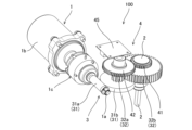
- FIG. 3 is a perspective view of the shift actuator according to the embodiment of the present invention with the housing removed.
- FIG. 4 is a sectional view taken along the line IV-IV in FIG. 2 of the drive section of the shift actuator according to the embodiment of the present invention.
- FIG. 5 is a sectional view taken along line VV in FIG. 2 of the main parts of the shift actuator according to the embodiment of the present invention.
- FIG. 1 is a schematic diagram of a vehicle V in which the shift actuator 100 is mounted.
- the vehicle V of this embodiment is a rear-wheel drive vehicle that is normally driven only by the rear wheels RT. Torque output from engine E is transmitted to rear wheels RT through automatic transmission TM.
- the shift actuator 100 is used to change the drive state of the vehicle V between two-wheel drive and four-wheel drive. By controlling shift actuator 100, vehicle V is configured to be able to switch between two-wheel drive driven only by rear wheels RT and four-wheel drive driven by front wheels FT and rear wheels RT.
- the vehicle V includes an engine E as a driving source, an automatic transmission TM that changes the speed of the engine E and outputs it, and a transfer TF that distributes the output torque of the automatic transmission TM to front wheels FT and rear wheels RT. Be prepared.
- the drive source of the vehicle V is not limited to the engine E, but may be a motor, or the engine E and the motor.
- the transfer TF includes a clutch CL that connects and disconnects power between the automatic transmission TM and the front wheels FT in the power transmission path from the engine E, and a shift actuator 100 that controls the operation of the clutch CL.
- the clutch CL is configured by, for example, a multi-plate wet clutch.
- the clutch CL When the clutch CL is engaged, the torque output from the engine E is transmitted not only to the rear wheels RT but also to the front wheels FT via the clutch CL.
- the clutch CL when the clutch CL is released, the torque output from the engine E is not transmitted to the front wheels FT but only to the rear wheels RT.
- Switching between rear-wheel drive and four-wheel drive is performed by switching a switch SW provided inside the vehicle interior.
- the controller C may automatically switch between rear-wheel drive and four-wheel drive according to the driving state of the vehicle V.
- FIG. 2 is an external view of the shift actuator 100.
- FIG. 3 is a perspective view of the shift actuator 100 with the housing 10 removed.
- FIG. 4 is a cross-sectional view of the drive section of the shift actuator 100.
- FIG. 5 is a cross-sectional view of the main parts of the shift actuator 100.
- the shift actuator 100 includes a motor 1 as a drive unit, a deceleration mechanism 3 that decelerates the rotation of the rotating shaft 1a of the motor 1 and transmits the rotation to the output shaft 2, and a It includes an angle detection mechanism 4 that detects a rotation angle, and a housing 10 that accommodates the deceleration mechanism 3 and the angle detection mechanism 4.
- the housing 10 includes a main body 10a in which a recess 10c for accommodating the deceleration mechanism 3 and the angle detection mechanism 4 is formed, and a cover 10b that covers the recess 10c.
- the motor 1 is controlled by a controller C that controls the vehicle V using a battery (not shown) mounted on the vehicle V as a power source. As shown in FIGS. 2 to 4, the motor 1 includes a rotating shaft 1a, a coil portion 1b that generates rotational power to rotate the rotating shaft 1a by receiving power from a battery, and a coil portion 1b that generates rotational power to rotate the rotating shaft 1a.
- An electromagnetic brake 1c for regulation is provided.
- the rotating shaft 1a of the motor 1 is rotatably supported by the housing 10 by a bearing 1d and a sleeve 1e.
- the rotating shaft 1a is arranged substantially perpendicular to the output shaft 2.
- the rotating shaft 1a is connected to a rotor (not shown) of the coil portion 1b.
- the coil portion 1b is fixed to the outer surface of the housing 10 with bolts 70 (see FIG. 4, etc.).
- the electromagnetic brake 1c is, for example, a non-excitation type electromagnetic brake.
- the electromagnetic brake 1c when a current is applied to the electromagnetic brake 1c, the brake is released and rotation of the rotating shaft 1a is allowed.
- the application of current to the electromagnetic brake 1c is cut off, the brake is activated and the rotation of the rotating shaft 1a is restricted.
- the rotating shaft 1a of the motor 1 is provided with a worm gear 31a as a first gear.
- the worm gear 31a is provided in a region between the bearing 1d and the sleeve 1e.
- the deceleration mechanism 3 includes a first deceleration mechanism 31 that decelerates the rotation of the rotating shaft 1a of the motor 1, and a second deceleration mechanism 32 that further decelerates the output rotation of the first deceleration mechanism 31. has.
- the first speed reduction mechanism 31 includes a worm gear 31a and a worm wheel 31b as a second gear that meshes with the worm gear 31a.
- the worm wheel 31b is rotatably supported by a shaft 5 whose end portion 5a is fixed to the housing 10.
- the second reduction mechanism 32 includes a spur gear 32a as a third gear that rotates integrally with the worm wheel 31b, and a spur gear 32b as a fourth gear that meshes with the spur gear 32a and is fixed to the output shaft 2.
- the spur gear 32a is rotatably supported by the shaft 5 and rotates together with the worm wheel 31b.
- the spur gear 32a and the worm wheel 31b are each manufactured separately, and they are coupled by adhesive or key coupling, so that they rotate as a unit.
- the spur gear 32a and the worm wheel 31b are held between the retaining ring 7 that is engaged with the shaft 5 and the bottom surface 10d of the recess 10c of the housing 10.
- the spur gear 32b is fixed to the output shaft 2 and rotates integrally with the output shaft 2.
- the number of teeth of the spur gear 32b is greater than the number of teeth of the spur gear 32a.
- the rotation of the rotating shaft 1a of the motor 1 is reduced at a predetermined gear ratio and transmitted to the output shaft 2.
- the shift actuator 100 further includes a plate 8 fixed within the housing 10 with bolts.
- One end (end 2a) of the output shaft 2 is rotatably supported by a bearing 2b attached to the main body 10a of the housing 10.
- the other end (end 2d) of the output shaft 2 is rotatably supported by the plate 8 via a sleeve 2c serving as a bearing.
- An end portion 2a of the output shaft 2 passes through the main body portion 10a of the housing 10 and is connected to a power transmission mechanism (not shown) for controlling the operation of the clutch CL described above.
- the output shaft 2 can be inserted between the main body 10a of the housing 10 and the plate 8 by inserting the end 2d into the through hole 8a formed in the plate 8 and fixing the plate 8 to the main body 10a of the housing 10. The shaft is held in place, and movement in the axial direction is restricted.
- the angle detection mechanism 4 meshes with a spur gear 41 as a fifth gear fixed to the output shaft 2 and rotates integrally with the output shaft 2, and is rotatably attached to the shaft 5.
- a spur gear 42 as a supported sixth gear, a magnet 43 attached to the spur gear 42 and rotating integrally with the spur gear 42, and an angle sensor 44 as an angle detector provided to face the magnet 43. and has.
- the spur gear 41 and the spur gear 42 constitute the speed reduction mechanism 40.
- the speed reduction mechanism 40 reduces the rotation angle of the output shaft 2 at a predetermined ratio and outputs the rotation angle of the spur gear 42 .
- the spur gear 42 has a cap portion 42a that covers the end portion 5b of the shaft 5, and a gear portion 42b that meshes with the spur gear 41.
- the spur gear 42 is supported so as to be rotatable relative to the shaft 5 so as to cover the end 5b of the shaft 5.
- the cap portion 42a includes a main body portion 42c to which the gear portion 42b is fixed on the outer periphery, a hole 42d formed in the main body portion 42c into which the end portion 5b of the shaft 5 is inserted, and a small diameter portion having an outer diameter smaller than that of the main body portion 42c. 42e, a stepped portion 42f constituted by the main body portion 42c and the small diameter portion 42e, and a projection portion 42g that is formed to protrude from the end surface of the small diameter portion 42e and to which the magnet 43 is fixed.
- the outer diameter of the main body 42c of the spur gear 42 is larger than the inner diameter of the through hole 8b formed in the plate 8.
- the spur gear 42 is configured such that the shaft 5 is inserted into the hole 42d of the spur gear 42, and the small diameter portion 42e is inserted into the through hole 8b formed in the plate 8, and the plate 8 is inserted into the main body 10a of the housing 10. By fixing, it is held between the end 5b of the shaft 5 and the plate 8. At this time, the stepped portion 42f comes into slidable contact with the plate 8, thereby restricting movement of the spur gear 42 in the axial direction of the shaft 5.
- the outer diameter of the small diameter portion 42e of the spur gear 42 is formed to be slightly smaller than the inner diameter of the through hole 8b formed in the plate 8. As a result, when the small diameter portion 42e is inserted into the through hole 8b formed in the plate 8, the spur gear 42 is restricted from moving in the radial direction by the plate 8.
- the cap part 42a and the gear part 42b may be formed separately and then formed by integrating them, or the cap part 42a and the gear part 42b may be formed from one member.
- a gear portion 42b may also be formed.
- the angle sensor 44 is attached to the substrate 45.
- the board 45 is attached to the cover 10b of the housing 10 with screws or the like.
- the rotation angle of the spur gear 42 detected by the angle sensor 44 is transmitted to the controller C (see FIG. 1). Note that the rotation angle of the spur gear 42 corresponds to the rotation angle obtained by reducing the rotation angle of the output shaft 2 by a predetermined ratio (reduction ratio) by the reduction gear mechanism 40.
- the plate 8 partitions the space within the recess 10c of the housing 10 into a space S1 where the speed reduction mechanism 3 is provided and a space S2 where the angle sensor 44 and the board 45 to which the angle sensor 44 is attached are provided.
- the plate 8 is provided between the speed reduction mechanism 3 and the substrate 45, in other words, so as to cover the speed reduction mechanism 3.
- the plate 8 not only has the function of partitioning the inside of the recess 10c into a space S1 and a space S2, but also has the function of separating the inside of the recess 10c into a space S1 and a space S2. It has a function of preventing the particles from adhering to the substrate 45.
- the plate 8 preferably completely partitions the recess 10c of the housing 10 into a space S1 and a space S2, that is, it is preferable to cover the entire space S1 where the deceleration mechanism 3 is provided. It is sufficient if it is provided between.
- the speed reduction mechanisms 3 the rotational speed of the worm gear 31a of the first speed reduction mechanism 31 is the fastest. Therefore, the lubricant applied near the worm gear 31a is likely to scatter. Further, as is clear from FIG. 5 and the like, there is a high possibility that the lubricant scattered by the rotation of the worm gear 31a will scatter toward the angle sensor 44 and the substrate 45 from the rotation direction of the worm gear 31a.
- the controller C applies a current to the electromagnetic brake 1c to release the rotation restriction on the rotation shaft 1a of the motor 1, and then the motor A current is applied to the coil portion 1b of No. 1.
- the rotating shaft 1a of the motor 1 rotates.
- the rotation of the rotating shaft 1 a is reduced in speed by the first reduction mechanism 31 and the second reduction mechanism 32 and transmitted to the output shaft 2 .
- the rotation of the output shaft 2 is transmitted to the power transmission mechanism of the transfer TF (see FIG. 1), and is converted into a fastening force that fastens the clutch CL.
- the controller C applies a current to the electromagnetic brake 1c to release the restriction on the rotation of the rotation shaft 1a of the motor 1, and then , a current is applied to the coil portion 1b of the motor 1 to rotate the rotating shaft 1a of the motor 1 in the opposite direction.
- the rotating shaft 1a of the motor 1 rotates in the opposite direction.
- the rotation of the rotating shaft 1 a is reduced in speed by the first reduction mechanism 31 and the second reduction mechanism 32 and transmitted to the output shaft 2 .
- the rotation of the output shaft 2 is transmitted to the power transmission mechanism of the transfer TF (see FIG. 1) and converted into a force that reduces the engagement force of the clutch CL.
- the shift actuator 100 of this embodiment includes the angle detection mechanism 4 having the deceleration mechanism 40 configured by the spur gear 41 and the spur gear 42, the variation range of the rotation angle of the output shaft 2 is 360 degrees (1 Even in the case where the rotation angle exceeds 360°, the range of variation in the rotation angle of the magnet 43 can be kept within 360° by adjusting the speed ratio of the spur gear 41 and the spur gear 42.
- the spur gear 42 to which the magnet 43 is attached is supported by the shaft 5 that supports the worm wheel 31b. Therefore, there is no need to separately provide a shaft for supporting the spur gear 42, so the device can be miniaturized.
- the shift actuator 100 of this embodiment includes an electromagnetic brake 1c that restricts rotation of the rotating shaft 1a of the motor 1.
- the electromagnetic brake 1c controls the rotation of the rotating shaft 1a of the motor 1 when the spring reaction force of the clutch CL acts on the output shaft 2 as a reverse torque, thereby reducing the output mechanically connected to the rotating shaft 1a. Regulates rotation of shaft 2.
- the shift actuator 100 since the shift actuator 100 includes the electromagnetic brake 1c, when a reverse torque is applied to the output shaft 2 due to the spring reaction force of the clutch CL, the output shaft 2 rotates and the clutch CL is prevented from being inadvertently activated. It is possible to prevent the drive force from being released or fastened, or from changing the amount of driving force distributed.
- the first reduction mechanism 31 is configured by a worm gear 31a and a worm wheel 31b.
- the power transmission efficiency when power is transmitted from the worm wheel 31b to the worm gear 31a is lower than the power transmission efficiency when power is transmitted from the worm gear 31a to the worm wheel 31b. Therefore, when the above-mentioned reverse torque acts on the first speed reduction mechanism 31 from the output shaft 2, a part of this reverse torque can be absorbed by the first speed reduction mechanism 31. Thereby, the torque in the opposite direction transmitted to the rotating shaft 1a of the motor 1 can be reduced, so that the electromagnetic brake 1c can be downsized.
- the rotating shaft 1a and the output shaft 2 are arranged to be substantially perpendicular to each other.
- the rotating shaft 1a and the output shaft 2 are arranged in parallel, when the shift actuator 100 is attached to the transfer TF, the coil portion 1b of the motor 1 is located in the axial direction of the output shaft 2, and the output It is necessary to secure a corresponding space in the axial direction of the shaft 2.
- the rotating shaft 1a and the output shaft 2 are arranged to be substantially perpendicular to each other, so there is a space for providing the coil portion 1b of the motor 1 in the axial direction of the output shaft 2. Since this eliminates the need for the shift actuator 100, the space required to install the shift actuator 100 can be reduced.
- the deceleration mechanism 3 includes the first deceleration mechanism 31 and the second deceleration mechanism 32 has been described as an example, but the present invention is not limited to this. It may be.
- the angle sensor 44 is provided to detect the rotation angle of the output shaft 2 of the shift actuator 100, but in addition to this, in order to directly detect the rotation angle of the output shaft 2, for example, the output shaft An angle sensor may be provided at a position facing the end portion 2d of 2.
- the rotation angle of the output shaft 2 is calculated from the rotation angle of the rotation shaft 1a of the motor 1 detected by a sensor that detects the rotation angle of the rotation shaft 1a of the motor 1. , may be used to control the motor 1.
- the shaft 5 is fixed to the main body 10a of the housing 10, but the invention is not limited to this.
- a bearing may be provided between the shaft 5 and the housing 10, and the shaft 5
- the shaft 5 and the worm wheel 31b may rotate together, or the shaft 5 and the spur gear 42 may rotate together.
- the spur gear 41 and the spur gear 42 constitute the speed reduction mechanism 40, but the spur gear 41 and the spur gear 42 may constitute the speed increasing mechanism.
- the speed increasing mechanism increases the rotation angle of the output shaft 2 at a predetermined ratio and outputs it as rotation of the spur gear 42.
- the resolution when detecting the rotation angle of the output shaft 2 can be improved.
- the shift actuator 100 includes a motor 1 having a rotating shaft 1a, a first reducing mechanism 31 that decelerates and outputs the rotation of the rotating shaft 1a, and a first reducing mechanism 31 that decelerates the output of the first reducing mechanism 31 and outputs it to the output shaft 2.
- the first reduction mechanism 31 includes a worm gear 31a (first gear) fixed to the rotation shaft 1a, and a worm gear 31a (first gear) fixed to the rotation shaft 1a.
- the second reduction mechanism 32 has a worm wheel 31b (second gear) that meshes with the worm wheel 31b (second gear) and is supported by the shaft 5, and the second reduction mechanism 32 is a spur gear that rotates integrally with the worm wheel 31b (second gear).
- the variation range of the rotation angle of the magnet 43 can be made within 360 degrees. This eliminates the need to count the number of rotations of the output shaft 2, so in the event of a temporary loss of power, for example, the counted number of rotations of the output shaft 2 will become unknown and the number of rotations of the output shaft 2 will be lost. It is possible to avoid a situation where the rotation angle cannot be detected.
- the spur gear 42 (sixth gear) is supported by the shaft 5 that supports the worm wheel 31b (second gear). Thereby, there is no need to separately provide a shaft that supports the spur gear 42 (sixth gear), so the device can be downsized.
- the spur gear 42 (sixth gear) is supported so as to be rotatable relative to the shaft 5 so as to cover the end 5b (one end) of the shaft 5.
- This configuration has a simpler structure than a configuration in which the spur gear 42 (sixth gear) is supported at an intermediate position in the axial direction of the shaft 5. Thereby, assembly efficiency can be improved.
- the magnet 43 is fixed to the spur gear 42 (sixth gear).
- the shift actuator 100 further includes a housing 10 that houses the first deceleration mechanism 31, the second deceleration mechanism 32, and the angle detection mechanism 4, and the end 5a (other end) of the shaft 5 is fixed to the housing 10.
- the shift actuator 100 further includes a plate 8 that partitions a space S1 in which the first deceleration mechanism 31 and the second deceleration mechanism 32 are provided and a space S2 in which an angle sensor 44 (angle detector) is provided in the housing 10. , the radial movement of the spur gear 42 (sixth gear) is restricted by the plate 8.
- the shift actuator 100 further includes a plate 8 that partitions a space S1 in which the first deceleration mechanism 31 and the second deceleration mechanism 32 are provided and a space S2 in which an angle sensor 44 (angle detector) is provided in the housing 10. , the movement of the spur gear 42 (sixth gear) in the axial direction of the shaft 5 is restricted by the plate 8.
- the first deceleration mechanism 31 is configured with the worm gear 31a and the worm wheel 31b, but it is not limited to this, and any combination of bevel gears, spur gears, etc. There may be.
Landscapes
- Engineering & Computer Science (AREA)
- General Engineering & Computer Science (AREA)
- Mechanical Engineering (AREA)
- Chemical & Material Sciences (AREA)
- Combustion & Propulsion (AREA)
- Transportation (AREA)
- Arrangement And Mounting Of Devices That Control Transmission Of Motive Force (AREA)
- Gear Transmission (AREA)
- Transmission Devices (AREA)
- Connection Of Motors, Electrical Generators, Mechanical Devices, And The Like (AREA)
Abstract
シフトアクチュエータ(100)は、回転軸(1a)の回転を減速して出力する第1減速機構(31)及び第2減速機構(32)と、出力軸2の回転角度を検出する角度検出機構(4)と、を備え、第1減速機構(31)は、回転軸(1a)に固定されたウォームギア(31a)と、ウォームギア(31a)と噛合し、シャフト(5)に支持されるウォームホイール(31b)と、を有し、角度検出機構(4)は、出力軸(2)と一体に回転する平歯車(41)と、平歯車(41)に噛合し、シャフト(5)に支持される平歯車(42)と、平歯車(42)と一体に回転する磁石(43)と、磁石(43)と対向するように設けられた角度センサ(44)と、を有する。
Description
本発明は、シフトアクチュエータに関するものである。
JP2011-57221Aには、シフトレールを駆動するモータと、モータの回転をシフトレールに伝えるギヤ機構と、シフトレールと共に回転する磁石と、磁石の回転角度に応じた出力を提供する磁気センサ素子とを有する自動車の駆動状態を切り替えるためのシフトアクチュエータが開示されている。
JP2011-57221Aに記載のシフトアクチュエータでは、出力軸の回転角度が360°を超えると、磁気センサ素子では回転角度を検出できなくなるおそれがある。
本発明の目的は、出力軸の回転角度が360°を超えても回転角度が検出できるシフトアクチュエータを提供することである。
本発明のある態様によれば、車両の駆動状態を二輪駆動と四輪駆動とに切り換えるためのシフトアクチュエータであって、回転軸を有するモータと、回転軸の回転を減速して出力する第1減速機構と、第1減速機構の出力を減速して出力軸に出力する第2減速機構と、出力軸の回転角度を検出する角度検出機構と、を備え、第1減速機構は、回転軸に固定された第1歯車と、第1歯車と噛合し、シャフトに支持される第2歯車と、を有し、第2減速機構は、第2歯車と一体に回転する第3歯車と、第3歯車と噛合し、出力軸に固定される第4歯車と、を有し、角度検出機構は、出力軸と一体に回転する第5歯車と、第5歯車に噛合し、シャフトに支持される第6歯車と、第6歯車と一体に回転する磁石と、磁石と対向するように設けられた角度検出器と、を有する。
以下、図面を参照して、本発明の実施形態に係るシフトアクチュエータ100について説明する。
まず、図1を参照しながら、シフトアクチュエータ100が搭載される車両Vの概略について説明する。なお、図1は、シフトアクチュエータ100が搭載される車両Vの概略図である。
本実施形態の車両Vは、通常は後輪RTのみで駆動する後輪駆動をベースとする車両である。エンジンEから出力されたトルクは、自動変速機TMを通じて後輪RTに伝達される。
シフトアクチュエータ100は、車両Vの駆動状態を二輪駆動と四輪駆動とに変更するために用いられる。シフトアクチュエータ100を制御することによって、車両Vは、後輪RTのみによって駆動する二輪駆動と、前輪FT及び後輪RTによって駆動する四輪駆動と、を切り換えることが可能に構成される。
車両Vは、駆動源としてのエンジンEと、エンジンEの回転を変速して出力する自動変速機TMと、自動変速機TMの出力トルクを前輪FT及び後輪RTに分配するトランスファTFと、を備える。なお、車両Vの駆動源は、エンジンEに限らず、モータ、あるいは、エンジンE及びモータであってもよい。
トランスファTFは、エンジンEからの動力伝達経路における自動変速機TMと前輪FTとの間の動力を断接するクラッチCLと、クラッチCLの動作を制御するシフトアクチュエータ100と、を有する。
クラッチCLは、例えば、多板式の湿式クラッチによって構成される。クラッチCLが締結されると、エンジンEから出力されたトルクは、後輪RTのみならず、クラッチCLを通じて前輪FTにも伝達される。これに対し、クラッチCLが解放されると、エンジンEから出力されたトルクは、前輪FTに伝達されず、後輪RTのみに伝達される。
後輪駆動と四輪駆動との切り換えは、車室内に設けられたスイッチSWを切り換えることにより行われる。なお、これに限らず、後輪駆動と四輪駆動との切り換えは、車両Vの走行状態に応じてコントローラCが自動的に切り換えるようにしてもよい。
次に、図2から図5を参照して、シフトアクチュエータ100の具体的な構成について説明する。図2は、シフトアクチュエータ100の外観図である。図3は、シフトアクチュエータ100のハウジング10を取り除いた状態での斜視図である。図4は、シフトアクチュエータ100の駆動部の断面図である。図5は、シフトアクチュエータ100の主要部の断面図である。
図2から図5に示すように、シフトアクチュエータ100は、駆動部としてのモータ1と、モータ1の回転軸1aの回転を減速して出力軸2に伝達する減速機構3と、出力軸2の回転角度を検出する角度検出機構4と、減速機構3及び角度検出機構4を収容するハウジング10と、を備える。
ハウジング10は、減速機構3と角度検出機構4とを収容する凹部10cが形成された本体部10aと、凹部10cを覆うカバー10bと、を有する。
モータ1は、車両Vに搭載されたバッテリ(図示せず)を電源として車両Vを制御するコントローラCによって制御される。図2から図4に示すように、モータ1は、回転軸1aと、バッテリからの電力の供給を受けて回転軸1aを回転させる回転動力を発生させるコイル部1bと、回転軸1aの回転を規制する電磁ブレーキ1cと、を備える。
図4に示すように、モータ1の回転軸1aは、軸受1d及びスリーブ1eによってハウジング10に対して回転可能に支持される。本実施形態では、図5などに示すように、回転軸1aは、出力軸2に対して略直交するように配置される。
回転軸1aは、コイル部1bのロータ(図示せず)に連結される。コイル部1bは、ハウジング10の外面にボルト70によって固定される(図4など参照)。
電磁ブレーキ1cは、例えば、無励磁作動型の電磁ブレーキである。電磁ブレーキ1cでは、電磁ブレーキ1cに電流が印加されると、ブレーキが解除され、回転軸1aの回転が許容される。これに対し、電磁ブレーキ1cへの電流の印加が遮断されると、ブレーキが作動し、回転軸1aの回転が規制される。
図4などに示すように、モータ1の回転軸1aには、第1歯車としてのウォームギア31aが設けられる。ウォームギア31aは、軸受1dとスリーブ1eの間の領域に設けられる。
図5などに示すように、減速機構3は、モータ1の回転軸1aの回転を減速する第1減速機構31と、第1減速機構31の出力回転をさらに減速する第2減速機構32と、を有する。
第1減速機構31は、ウォームギア31aと、ウォームギア31aに噛合する第2歯車としてのウォームホイール31bと、を有する。ウォームホイール31bは、ハウジング10に端部5aが固定されたシャフト5に回転可能に支持される。
第2減速機構32は、ウォームホイール31bと一体に回転する第3歯車としての平歯車32aと、平歯車32aと噛合し、出力軸2に固定された第4歯車としての平歯車32bと、を有する。
平歯車32aは、シャフト5に回転可能に支持されるとともに、ウォームホイール31bと一体に回転する。具体的には、平歯車32aとウォームホイール31bは、それぞれ個別に製作され、これらは、接着やキー結合などにより結合されることで、一体となって回転する。平歯車32aとウォームホイール31bは、シャフト5に係止された止め輪7とハウジング10の凹部10cの底面10dとの間で保持される。
平歯車32bは、出力軸2に固定され、出力軸2と一体になって回転する。平歯車32bの歯数は、平歯車32aの歯数より多い。
このように構成された第1減速機構31及び第2減速機構32によって、モータ1の回転軸1aの回転は、所定の変速比で減速され、出力軸2に伝達される。
図5に示すように、シフトアクチュエータ100は、ハウジング10内にボルトによって固定されたプレート8をさらに備える。
出力軸2の一端(端部2a)側は、ハウジング10の本体部10aに取り付けられた軸受2bによって回転可能に支持される。また、出力軸2の他端(端部2d)側は、プレート8に軸受としてのスリーブ2cを介して回転可能に支持される。出力軸2の端部2aは、ハウジング10の本体部10aを貫通して、上述のクラッチCLの動作を制御するための動力伝達機構(図示せず)に接続される。また、出力軸2は、端部2dをプレート8に形成された貫通孔8aに挿入し、プレート8をハウジング10の本体部10aに固定することで、ハウジング10の本体部10aとプレート8の間において保持されて、軸方向の移動が規制される。
図5に示すように、角度検出機構4は、出力軸2に固定され出力軸2と一体に回転する第5歯車としての平歯車41と、平歯車41に噛合し、シャフト5に回転可能に支持される第6歯車としての平歯車42と、平歯車42に取り付けられ、平歯車42と一体に回転する磁石43と、磁石43と対向するように設けられた角度検出器としての角度センサ44と、を有する。
本実施形態では、平歯車41と平歯車42は、減速機構40を構成する。減速機構40は、出力軸2の回転角度を所定の比率で減少して平歯車42の回転として出力する。
図5に示すように、平歯車42は、シャフト5の端部5bを覆うキャップ部42aと、平歯車41と噛合する歯車部42bと、を有する。平歯車42は、シャフト5の端部5bを覆うようにして、シャフト5に対して相対回転可能に支持される。
キャップ部42aは、外周に歯車部42bが固定される本体部42cと、本体部42cに形成され、シャフト5の端部5bが挿入される孔42dと、本体部42cより外径の小さな小径部42eと、本体部42cと小径部42eとによって構成される段差部42fと、小径部42eの端面から突出するように形成され、先端に磁石43が固定される突起部42gと、を有する。
平歯車42の本体部42cの外径は、プレート8に形成された貫通孔8bの内径より大きく形成される。平歯車42は、平歯車42の孔42dにシャフト5が挿入されるとともに、プレート8に形成された貫通孔8bに小径部42eが挿入された状態で、プレート8をハウジング10の本体部10aに固定することにより、シャフト5の端部5bとプレート8の間に保持される。このとき、段差部42fがプレート8と摺動可能に接することで、平歯車42のシャフト5の軸方向における移動が規制される。
平歯車42の小径部42eの外径は、プレート8に形成された貫通孔8bの内径よりわずかに小さく形成される。これにより、平歯車42は、プレート8に形成された貫通孔8bに小径部42eが挿入された状態では、プレート8によって径方向の移動が規制される。
なお、平歯車42を形成する場合には、キャップ部42aと歯車部42bとを別体で形成した後、これらを一体にすることで形成してもよいし、1つの部材からキャップ部42aと歯車部42bとを形成してもよい。
角度センサ44は、基板45に取り付けられる。基板45は、ハウジング10のカバー10bにビスなどによって取り付けられる。角度センサ44によって検出された平歯車42の回転角度は、コントローラC(図1参照)に送信される。なお、平歯車42の回転角度は、出力軸2の回転角度を減速機構40によって所定の比率(減速比)で減少させた回転角度に相当する。
プレート8は、ハウジング10の凹部10c内の空間を、減速機構3が設けられる空間S1と、角度センサ44及び角度センサ44が取り付けられる基板45が設けられる空間S2とに仕切る。プレート8は、減速機構3と基板45との間、言い換えると、減速機構3を覆うように設けられる。プレート8は、凹部10c内を空間S1と空間S2に仕切る機能だけでなく、減速機構3を構成するギアなどに塗布された潤滑剤がギアの回転によって飛散した場合に、潤滑剤が角度センサ44や基板45に付着することを防止する機能を有する。
なお、プレート8は、ハウジング10の凹部10cを空間S1と空間S2とに完全に仕切る、つまり、減速機構3が設けられる空間S1全体を覆うことが好ましいが、少なくとも第1減速機構31と基板45との間に設けられていればよい。減速機構3の中で、第1減速機構31のウォームギア31aの回転速度が最も速い。このため、ウォームギア31a近傍に塗布された潤滑剤は飛散しやすい。また、図5などから明らかなように、ウォームギア31aの回転方向から、ウォームギア31aの回転によって飛散する潤滑剤は、角度センサ44や基板45の方向に向かって飛散する可能性が高い。そこで、プレート8を少なく第1減速機構31と基板45との間に設けることができれば、角度センサ44や基板45に潤滑剤が付着することを防止できる。これにより、角度センサ44や基板45に潤滑剤が付着することによって、角度センサ44の検出精度が低下したり、あるいは、基板45において電気的な短絡が発生することを防止できる。
このように構成されたシフトアクチュエータ100の制御の一例を説明する。
スイッチSW(図1参照)が四輪駆動に切り換える位置に操作されると、コントローラCは、電磁ブレーキ1cに電流を印加して、モータ1の回転軸1aにおける回転の規制を解除した後、モータ1のコイル部1bに電流を印加する。これにより、モータ1の回転軸1aが回転する。回転軸1aの回転は、第1減速機構31及び第2減速機構32によって減速されて出力軸2に伝達される。出力軸2の回転は、トランスファTF(図1参照)の動力伝達機構に伝達され、クラッチCLを締結する締結力に変換される。このようにして、クラッチCLが締結されると、エンジンEから出力されたトルクは、後輪RTに伝達されるとともに、クラッチCLを通じて前輪FTに伝達される。そして、コントローラCが、角度センサ44の検出値に基づいて、出力軸2の回転角度がクラッチCLが締結されたと判断できる回転角度まで回転したと判断すると、コントローラCは、モータ1のコイル部1bへの電流の印加を停止するとともに、電磁ブレーキ1cへの電流の印加を停止する。これにより、モータ1の回転軸1aの回転が規制される。このとき、出力軸2は、モータ1の回転軸1aと機械的に接続されているため、出力軸2の回転も規制される。これにより、クラッチCLは締結状態に維持される。
反対に、スイッチSW(図1参照)が二輪駆動に切り換える位置に操作されると、コントローラCは、電磁ブレーキ1cに電流を印加して、モータ1の回転軸1aにおける回転の規制を解除した後、モータ1のコイル部1bにモータ1の回転軸1aを逆方向に回転させる電流を印加する。これにより、モータ1の回転軸1aが逆方向に回転する。回転軸1aの回転は、第1減速機構31及び第2減速機構32によって減速されて出力軸2に伝達される。出力軸2の回転は、トランスファTF(図1参照)の動力伝達機構に伝達され、クラッチCLの締結力を減少させる方向の力に変換される。このようにして、クラッチCLが解放されると、エンジンEから出力されたトルクは、前輪FTには伝達されず、後輪RTのみに伝達される。そして、コントローラCが、角度センサ44の検出値に基づいて、出力軸2の回転角度がクラッチCLが解放されたと判断できる回転角度まで回転したと判断すると、コントローラCは、モータ1のコイル部1bへの電流の印加を停止するとともに、電磁ブレーキ1cへの電流の印加を停止する。これにより、モータ1の回転軸1aの回転が規制される。このとき、出力軸2は、モータ1の回転軸1aと機械的に接続されているため、出力軸2の回転も規制される。これにより、クラッチCLは解放状態に維持される。
なお、この例では、クラッチCLを完全に締結、あるいは解放する場合を説明したが、クラッチCLの締結状態(トルク容量)を制御することで、前輪FTと後輪RTとの駆動力の分配量を制御することも可能である。
本実施形態のシフトアクチュエータ100は、平歯車41と平歯車42とによって構成された減速機構40を有する角度検出機構4を備えているので、出力軸2の回転角度の変動範囲が360°(1回転)を超えるような場合であっても、平歯車41と平歯車42の変速比を調整することによって磁石43の回転角度の変動範囲を360°以内にすることができる。これにより、出力軸2の回転数をカウントする必要がなくなるので、例えば、一時的に電源が喪失してしまった場合などに、カウントされた出力軸2の回転数が不明となり、出力軸2の回転角度が検出できないといった事態を避けることができる。
また、本実施形態のシフトアクチュエータ100では、磁石43が取り付けられた平歯車42がウォームホイール31bを支持するシャフト5によって支持されている。これにより、平歯車42を支持する軸を別途設ける必要がないので、装置を小型化できる。
本実施形態のシフトアクチュエータ100は、モータ1の回転軸1aの回転を規制する電磁ブレーキ1cを備えている。電磁ブレーキ1cは、クラッチCLのばね反力などが出力軸2に逆トルクとして作用した場合に、モータ1の回転軸1aの回転を規制することで、回転軸1aと機械的に接続された出力軸2の回転を規制する。このように、シフトアクチュエータ100が、電磁ブレーキ1cを備えることにより、クラッチCLのばね反力などが出力軸2に逆トルクが作用した場合に、出力軸2が回転することでクラッチCLが不用意に解放、または締結されてしまうこと、あるいは、駆動力の分配量が変化してしまうことを防止できる。
そして、本実施形態のシフトアクチュエータ100では、第1減速機構31が、ウォームギア31aとウォームホイール31bとによって構成されている。ウォームホイール31bからウォームギア31aへ動力を伝達する場合の動力伝達効率は、ウォームギア31aからウォームホイール31bへ動力を伝達する場合の動力伝達効率と比較して低い。このため、上述のような逆トルクが出力軸2から第1減速機構31に作用した場合に、この逆トルクの一部を第1減速機構31によって吸収させることができる。これにより、モータ1の回転軸1aに伝達される逆方向のトルクを小さくできるので、電磁ブレーキ1cを小型化することができる。
さらに、本実施形態のシフトアクチュエータ100では、回転軸1aと出力軸2が略直交するように配置されている。回転軸1aと出力軸2とが平行に配置された構成では、シフトアクチュエータ100をトランスファTFに取り付けた際に、モータ1のコイル部1bが出力軸2の軸線方向に位置することになり、出力軸2の軸線方向にその分スペースを確保する必要がある。これに対し、本実施形態のシフトアクチュエータ100では、回転軸1aと出力軸2が略直交するように配置されているので、出力軸2の軸線方向にモータ1のコイル部1bを設けるためのスペースが不要となるため、シフトアクチュエータ100を設置するためスペースを小さくすることができる。
上記実施形態では、減速機構3が、第1減速機構31及び第2減速機構32を有している場合を例として説明したが、これに限らず、減速機構3は、第1減速機構31のみであってもよい。
上記実施形態では、シフトアクチュエータ100の出力軸2の回転角度を検出するために角度センサ44を設けているが、これに加え、出力軸2の回転角度を直接検出するために、例えば、出力軸2の端部2dに対向する位置に角度センサを設けてもよい。あるいは、角度センサ44による検出値に加え、モータ1の回転軸1aの回転角度を検出するセンサによって検出されたモータ1の回転軸1aの回転角度から、出力軸2の回転角度を算出するようにし、モータ1の制御に用いてもよい。
また、上記実施形態では、シャフト5がハウジング10の本体部10aに固定されている場合を例に説明したが、これに限らず、例えば、シャフト5とハウジング10の間に軸受を設け、シャフト5とウォームホイール31bとが一体に回転する、あるいは、シャフト5と平歯車42とが一体に回転するようにしてもよい。
上記実施形態では、平歯車41と平歯車42が減速機構40を構成する場合を説明が、平歯車41と平歯車42が増速機構を構成してもよい。この場合には、増速機構は、出力軸2の回転角を所定の比率で増加して平歯車42の回転として出力する。このような増速機構を用いた場合には、出力軸2の回転角を検出する際の分解能を高めることができる。
以上のように構成された本発明の実施形態の構成、作用、及び効果をまとめて説明する。
シフトアクチュエータ100は、回転軸1aを有するモータ1と、回転軸1aの回転を減速して出力する第1減速機構31と、第1減速機構31の出力を減速して出力軸2に出力する第2減速機構32と、出力軸2の回転角度を検出する角度検出機構4と、を備え、第1減速機構31は、回転軸1aに固定されたウォームギア31a(第1歯車)と、ウォームギア31a(第1歯車)と噛合し、シャフト5に支持されるウォームホイール31b(第2歯車)と、を有し、第2減速機構32は、ウォームホイール31b(第2歯車)と一体に回転する平歯車32a(第3歯車)と、平歯車32a(第3歯車)と噛合し、出力軸2に固定される平歯車32b(第4歯車)と、を有し、角度検出機構4は、出力軸2と一体に回転する平歯車41(第5歯車)と、平歯車41(第5歯車)に噛合し、シャフト5に支持される平歯車42(第6歯車)と、平歯車42(第6歯車)と一体に回転する磁石43と、磁石43と対向するように設けられた角度センサ44(角度検出器)と、を有する。
この構成では、出力軸2の回転角度の変動範囲が360°(1回転)を超えるような場合であっても、平歯車41(第5歯車)と平歯車42(第6歯車)の変速比を調整することによって磁石43の回転角度の変動範囲を360°以内にすることができる。これにより、出力軸2の回転数をカウントする必要がなくなるので、例えば、一時的に電源が喪失してしまった場合などに、カウントされた出力軸2の回転数が不明となり、出力軸2の回転角度が検出できないといった事態を避けることができる。
また、この構成では、平歯車42(第6歯車)をウォームホイール31b(第2歯車)を支持するシャフト5によって支持する。これにより、平歯車42(第6歯車)を支持する軸を別途設ける必要がないので、装置を小型化できる。
シフトアクチュエータ100では、平歯車42(第6歯車)は、シャフト5の端部5b(一端)を覆うようにして、シャフト5に対して相対回転可能に支持される。
この構成では、平歯車42(第6歯車)をシャフト5の軸方向における中間位置に支持する構成に比べて、構造が簡単になる。これにより、組立効率を向上させることができる。
シフトアクチュエータ100では、磁石43は、平歯車42(第6歯車)に固定されている。
この構成では、平歯車42(第6歯車)に伝達された回転角度をそのまま角度センサ44(角度検出器)に対して伝えることができる。
シフトアクチュエータ100は、第1減速機構31、第2減速機構32、及び角度検出機構4を収容するハウジング10をさらに備え、シャフト5の端部5a(他端)は、ハウジング10に固定される。
この構成では、シャフト5をハウジング10に固定しているので、シャフト5を回転可能に支持する軸受が不要になる。これにより、コストの上昇を抑制できる。
シフトアクチュエータ100は、ハウジング10内において、第1減速機構31及び第2減速機構32が設けられる空間S1と、角度センサ44(角度検出器)が設けられる空間S2と、を仕切るプレート8をさらに備え、平歯車42(第6歯車)は、径方向の移動がプレート8によって規制される。
この構成では、平歯車42(第6歯車)の径方向の移動がプレート8によって規制されるので、平歯車42(第6歯車)と一体に回転する磁石43の径方向のブレを抑制することができる。これにより、回転角度の検出精度の低下を防止できる。
シフトアクチュエータ100は、ハウジング10内において、第1減速機構31及び第2減速機構32が設けられる空間S1と、角度センサ44(角度検出器)が設けられる空間S2と、を仕切るプレート8をさらに備え、平歯車42(第6歯車)は、シャフト5の軸方向における移動がプレート8によって規制される。
この構成では、平歯車42(第6歯車)のシャフト5の軸方向における移動がプレート8によって規制されるので、平歯車42(第6歯車)と一体に回転する磁石43の軸方向のブレを抑制することができる。これにより、回転角度の検出精度の低下を防止できる。
以上、本発明の実施形態について説明したが、上記実施形態は本発明の適用例の一部を示したに過ぎず、本発明の技術的範囲を上記実施形態の具体的構成に限定する趣旨ではない。
上記実施形態では、第1減速機構31をウォームギア31aとウォームホイール31bで構成した場合を例に説明したが、これに限らず、傘歯車の組み合わせや、平歯車の組み合わせなど、どのようなものであってもよい。
本願は、2022年3月30日に日本国特許庁に出願された特願2022-57593号に基づく優先権を主張し、この出願の全ての内容は参照により本明細書に組み込まれる。
Claims (6)
- 車両の駆動状態を二輪駆動と四輪駆動とに切り換えるためのシフトアクチュエータであって、
回転軸を有するモータと、
前記回転軸の回転を減速して出力する第1減速機構と、
前記第1減速機構の出力を減速して出力軸に出力する第2減速機構と、
前記出力軸の回転角度を検出する角度検出機構と、を備え、
前記第1減速機構は、
前記回転軸に固定された第1歯車と、
前記第1歯車と噛合し、シャフトに支持される第2歯車と、を有し、
前記第2減速機構は、
前記第2歯車と一体に回転する第3歯車と、
前記第3歯車と噛合し、前記出力軸に固定される第4歯車と、を有し、
前記角度検出機構は、
前記出力軸と一体に回転する第5歯車と、
前記第5歯車に噛合し、前記シャフトに支持される第6歯車と、
前記第6歯車と一体に回転する磁石と、
前記磁石と対向するように設けられた角度検出器と、を有するシフトアクチュエータ。 - 請求項1に記載のシフトアクチュエータであって、
前記第6歯車は、前記シャフトの一端を覆うようにして、前記シャフトに対して相対回転可能に支持されるシフトアクチュエータ。 - 請求項1に記載のシフトアクチュエータであって、
前記磁石は、前記第6歯車に固定されているシフトアクチュエータ。 - 請求項1に記載のシフトアクチュエータであって、
前記第1減速機構、前記第2減速機構、及び前記角度検出機構を収容するハウジングをさらに備え、
前記シャフトの他端は、前記ハウジングに固定されるシフトアクチュエータ。 - 請求項4に記載のシフトアクチュエータであって、
前記ハウジング内において、前記第1減速機構及び前記第2減速機構が設けられる空間と、前記角度検出器が設けられる空間と、を仕切るプレートをさらに備え、
前記第6歯車は、径方向の移動が前記プレートによって規制されるシフトアクチュエータ。 - 請求項4に記載のシフトアクチュエータであって、
前記ハウジング内において、前記第1減速機構及び前記第2減速機構が設けられる空間と、前記角度検出器が設けられる空間と、を仕切るプレートをさらに備え、
前記第6歯車は、前記シャフトの軸方向における移動が前記プレートによって規制されるシフトアクチュエータ。
Applications Claiming Priority (2)
| Application Number | Priority Date | Filing Date | Title |
|---|---|---|---|
| JP2022057593A JP7738512B2 (ja) | 2022-03-30 | 2022-03-30 | シフトアクチュエータ |
| JP2022-057593 | 2022-03-30 |
Publications (1)
| Publication Number | Publication Date |
|---|---|
| WO2023189604A1 true WO2023189604A1 (ja) | 2023-10-05 |
Family
ID=88201588
Family Applications (1)
| Application Number | Title | Priority Date | Filing Date |
|---|---|---|---|
| PCT/JP2023/010109 Ceased WO2023189604A1 (ja) | 2022-03-30 | 2023-03-15 | シフトアクチュエータ |
Country Status (2)
| Country | Link |
|---|---|
| JP (1) | JP7738512B2 (ja) |
| WO (1) | WO2023189604A1 (ja) |
Citations (4)
| Publication number | Priority date | Publication date | Assignee | Title |
|---|---|---|---|---|
| JP2005204468A (ja) * | 2004-01-19 | 2005-07-28 | Jidosha Denki Kogyo Co Ltd | 電磁クラッチ付モータ |
| JP2007168575A (ja) * | 2005-12-21 | 2007-07-05 | Univance Corp | 駆動切換アクチュエータ及び2輪・4輪駆動切換装置 |
| JP2009264504A (ja) * | 2008-04-25 | 2009-11-12 | Aisan Ind Co Ltd | 弁駆動装置 |
| JP2016052841A (ja) * | 2014-09-04 | 2016-04-14 | アイシン精機株式会社 | 駆動切換装置 |
-
2022
- 2022-03-30 JP JP2022057593A patent/JP7738512B2/ja active Active
-
2023
- 2023-03-15 WO PCT/JP2023/010109 patent/WO2023189604A1/ja not_active Ceased
Patent Citations (4)
| Publication number | Priority date | Publication date | Assignee | Title |
|---|---|---|---|---|
| JP2005204468A (ja) * | 2004-01-19 | 2005-07-28 | Jidosha Denki Kogyo Co Ltd | 電磁クラッチ付モータ |
| JP2007168575A (ja) * | 2005-12-21 | 2007-07-05 | Univance Corp | 駆動切換アクチュエータ及び2輪・4輪駆動切換装置 |
| JP2009264504A (ja) * | 2008-04-25 | 2009-11-12 | Aisan Ind Co Ltd | 弁駆動装置 |
| JP2016052841A (ja) * | 2014-09-04 | 2016-04-14 | アイシン精機株式会社 | 駆動切換装置 |
Also Published As
| Publication number | Publication date |
|---|---|
| JP2023149169A (ja) | 2023-10-13 |
| JP7738512B2 (ja) | 2025-09-12 |
Similar Documents
| Publication | Publication Date | Title |
|---|---|---|
| JP5002142B2 (ja) | 減速駆動装置 | |
| JP5387769B2 (ja) | パーキングロック装置 | |
| JP4699725B2 (ja) | モータリトラクタ | |
| US20080105009A1 (en) | Electric steering lock system | |
| KR20040062450A (ko) | 로크 검출 센서 | |
| WO2012039313A1 (ja) | 車両用ドア駆動装置 | |
| JP3699371B2 (ja) | インホイールモータ型駆動ユニットおよびハイブリッドシステム | |
| CN111692326B (zh) | 驱动装置、机器人及图像形成装置 | |
| WO2023189604A1 (ja) | シフトアクチュエータ | |
| JP7256440B2 (ja) | センサ | |
| JP2023149172A (ja) | シフトアクチュエータ | |
| US20140150587A1 (en) | Transfer | |
| WO2018168857A1 (ja) | 動力伝達装置、及び自動二輪車 | |
| JP2023149168A (ja) | シフトアクチュエータ | |
| CN110397734B (zh) | 马达单元 | |
| JP4980595B2 (ja) | シフトレンジ切替装置 | |
| CN109099144B (zh) | 换档装置 | |
| WO2012137427A1 (ja) | ハブユニットおよび電動自転車 | |
| EP1338493B1 (en) | Mechanism with variable transmission ratio | |
| JP2022083868A (ja) | 車両用駆動装置 | |
| JP2005042846A (ja) | 減速駆動装置 | |
| CN115325129A (zh) | 一种差速结构和车辆 | |
| JP7714406B2 (ja) | ハイブリッド電動車両の歯打ち音低減装置 | |
| JP3823070B2 (ja) | 駆動装置 | |
| JP2014130266A (ja) | 回転体ロック機構および回転板駆動装置 |
Legal Events
| Date | Code | Title | Description |
|---|---|---|---|
| 121 | Ep: the epo has been informed by wipo that ep was designated in this application |
Ref document number: 23779622 Country of ref document: EP Kind code of ref document: A1 |
|
| NENP | Non-entry into the national phase |
Ref country code: DE |
|
| 122 | Ep: pct application non-entry in european phase |
Ref document number: 23779622 Country of ref document: EP Kind code of ref document: A1 |