WO2023189232A1 - ヒートパイプ用ウイック、それを用いたヒートパイプ、冷却ユニット及び冷却システム - Google Patents
ヒートパイプ用ウイック、それを用いたヒートパイプ、冷却ユニット及び冷却システム Download PDFInfo
- Publication number
- WO2023189232A1 WO2023189232A1 PCT/JP2023/008257 JP2023008257W WO2023189232A1 WO 2023189232 A1 WO2023189232 A1 WO 2023189232A1 JP 2023008257 W JP2023008257 W JP 2023008257W WO 2023189232 A1 WO2023189232 A1 WO 2023189232A1
- Authority
- WO
- WIPO (PCT)
- Prior art keywords
- fiber
- nonwoven fabric
- wick
- metal
- sparse
- Prior art date
- Legal status (The legal status is an assumption and is not a legal conclusion. Google has not performed a legal analysis and makes no representation as to the accuracy of the status listed.)
- Ceased
Links
Images




Classifications
-
- F—MECHANICAL ENGINEERING; LIGHTING; HEATING; WEAPONS; BLASTING
- F28—HEAT EXCHANGE IN GENERAL
- F28D—HEAT-EXCHANGE APPARATUS, NOT PROVIDED FOR IN ANOTHER SUBCLASS, IN WHICH THE HEAT-EXCHANGE MEDIA DO NOT COME INTO DIRECT CONTACT
- F28D15/00—Heat-exchange apparatus with the intermediate heat-transfer medium in closed tubes passing into or through the conduit walls ; Heat-exchange apparatus employing intermediate heat-transfer medium or bodies
- F28D15/02—Heat-exchange apparatus with the intermediate heat-transfer medium in closed tubes passing into or through the conduit walls ; Heat-exchange apparatus employing intermediate heat-transfer medium or bodies in which the medium condenses and evaporates, e.g. heat pipes
-
- F—MECHANICAL ENGINEERING; LIGHTING; HEATING; WEAPONS; BLASTING
- F28—HEAT EXCHANGE IN GENERAL
- F28D—HEAT-EXCHANGE APPARATUS, NOT PROVIDED FOR IN ANOTHER SUBCLASS, IN WHICH THE HEAT-EXCHANGE MEDIA DO NOT COME INTO DIRECT CONTACT
- F28D15/00—Heat-exchange apparatus with the intermediate heat-transfer medium in closed tubes passing into or through the conduit walls ; Heat-exchange apparatus employing intermediate heat-transfer medium or bodies
- F28D15/02—Heat-exchange apparatus with the intermediate heat-transfer medium in closed tubes passing into or through the conduit walls ; Heat-exchange apparatus employing intermediate heat-transfer medium or bodies in which the medium condenses and evaporates, e.g. heat pipes
- F28D15/04—Heat-exchange apparatus with the intermediate heat-transfer medium in closed tubes passing into or through the conduit walls ; Heat-exchange apparatus employing intermediate heat-transfer medium or bodies in which the medium condenses and evaporates, e.g. heat pipes with tubes having a capillary structure
Definitions
- the present invention relates to a wick for a heat pipe, a heat pipe using the same, a cooling unit, and a cooling system.
- a heat pipe has a porous wick, mainly made of metal with high thermal conductivity, arranged along the inner wall surface, and a liquid that acts as a heat medium is sealed inside the inner wall, and both ends of the heat pipe are closed to reduce the pressure inside. Those that did are common.
- the liquid evaporates and the evaporator moves to the other end, dissipates the heat, condenses and condenses, and turns into a liquid.
- the condensed liquid moves through the heat pipe wick (hereinafter simply referred to as the wick in this specification) by capillary action, returns to its original state, evaporates again, and circulates inside the heat pipe to transfer heat. .
- the present invention has been made in view of the above-mentioned circumstances, and allows the vaporized body in the heat pipe to move well inside the metal fiber nonwoven fabric by capillary action, thereby efficiently controlling the reflux.
- the purpose of the present invention is to provide a wick, a heat pipe, a cooling unit, and a cooling system using the wick.
- a wick for a heat pipe having a metal fiber nonwoven fabric characterized in that the metal fiber nonwoven fabric has a fiber sparse portion and a fiber dense portion where the metal fiber nonwoven fabric has fewer voids than the fiber sparse portion.
- Wick for heat pipes [2] The wick for a heat pipe according to [1], wherein the fiber sparse portion has a convex portion and the fiber dense portion has a concave portion.
- the space factor of the metal fiber nonwoven fabric in the fiber sparse portion is 30% to 60%, and the space factor of the metal fiber nonwoven fabric in the fiber dense portion is 50% to 80% [1 ] or the wick for a heat pipe according to [2].
- a cooling unit comprising the heat pipe of [4] above.
- a cooling system comprising the cooling unit of [5] above.
- FIG. 1 is a schematic perspective view showing a wick according to the present invention.
- FIG. 1 is a schematic perspective view showing a wick according to the present invention.
- FIG. 1 is a schematic perspective view showing a wick according to the present invention.
- FIG. 1 is a schematic perspective view showing a wick according to the present invention.
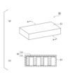
- 1 is a schematic perspective view and a sectional view showing a heat pipe according to the present invention.
- FIG. 2 is a sectional view showing a heat pipe according to the present invention.
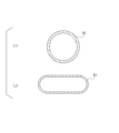
- FIG. 3 is a sectional view showing a heat pipe container according to the present invention.
- 1 is a schematic diagram showing an example of a conventional cooling unit and cooling system and a cooling unit and cooling system according to the present invention.
- FIG. 1(a) is a schematic perspective view of the wick 10 in the first embodiment
- FIG. 1(b) is a schematic perspective view of the back side of FIG. 1(a).
- the wick 10 shown in FIG. 1 has a sparse fiber part (hereinafter referred to as a sparse fiber part) 11 in which the metal fiber nonwoven fabric has many voids and a dense fiber part (hereinafter referred to as a dense fiber part) in which the metal fiber nonwoven fabric has fewer voids than the sparse fiber part. Consists of 12.
- the wick 10 is composed of a plurality of sparse fiber sections 11 and a plurality of dense fiber sections 12.
- the sparse fiber portions 11 and the dense fiber portions 12 each have a rectangular parallelepiped shape, and the sparse fiber portions 11 and the dense fiber portions 12 are alternately adjacent to each other.
- the sparse fiber portion 11 is a convex portion
- the dense fiber portion 12 is a concave portion.
- the evaporator vaporized inside the sparse fiber section 11 adjacent to the heat generating section diffuses into the sparse fiber section 11, and the sparse fiber section 11 and the fiber It diffuses between the sparse portion 11 (dense fiber portion 12).
- the diffused evaporator dissipates heat in the dense fiber section 12 adjacent to the cooling section, condenses and condenses, and turns into liquid.Then, the diffused evaporator is transmitted through the fiber surfaces of the sparse fiber section 11 and the dense fiber section 12, and the working fluid is Reflux can occur by returning to the heat generating part.
- the thickness of the sparse fiber portion 11 is not particularly limited, but is preferably 200 ⁇ m or more and 5000 ⁇ m or less, more preferably 500 ⁇ m or more and 4000 ⁇ m or less, and even more preferably 1000 ⁇ m or more and 2000 ⁇ m or less.
- a surface area for efficiently vaporizing the working fluid can be obtained.
- the thickness of the sparse fiber section 11 is 5000 ⁇ m or less, the liquefied working fluid does not pass through the inside of the sparse fiber section 11 and move to the heat generating section, so that the effect of refluxing the working fluid can be obtained.
- the thickness of the dense fiber portion 12 is not particularly limited, but is preferably 10 ⁇ m or more and 300 ⁇ m or less, more preferably 20 ⁇ m or more and 200 ⁇ m or less, and even more preferably 50 ⁇ m or more and 100 ⁇ m or less.
- the thickness of the dense fiber portion 12 is 10 ⁇ m or more, a surface area sufficient to condense the working fluid can be obtained.
- the thickness of the dense fiber portion 12 is 300 ⁇ m or less, it is possible to suppress the vaporized working fluid from accumulating inside the fiber structure of the dense portion, and it is possible to obtain the effect of increasing the amount of reflux liquid.
- the thickness of the wick in this specification refers to the case where, for example, an arbitrary number of measurement points on the wick are measured using a film thickness meter using an air terminal drop method (for example, Digimatic Indicator ID-C112X manufactured by Mitutoyo). means the average value of
- the wick 10 in the first embodiment can be manufactured as follows. A metal fiber nonwoven fabric is manufactured as described below, and a substantially flat sheet-shaped metal fiber nonwoven fabric is prepared. Next, a sheet-shaped metal fiber non-woven fabric is placed on a base, and pressure is applied from the surface of the sheet-shaped metal fiber non-woven fabric using a mold having the shape of the fiber-dense portion 12 prepared separately. In this way, by applying pressure by the formwork so that the shape of the wick 10 in Embodiment 1 is applied, the wick 10 is formed in which the sparse fiber portion 11 has a convex portion and the dense fiber portion 12 has a concave portion. can be manufactured.
- FIG. 2(c) is a schematic perspective view of the wick 20 in the second embodiment
- FIG. 2(d) is a schematic perspective view of the back side of FIG. 2(c).
- the wick 20 shown in FIG. 2 is composed of a sparse fiber section 21 and a dense fiber section 22.
- the wick 20 is composed of a plurality of sparse fiber portions 21 and a sheet-like dense fiber portion 22.
- the wick 20 according to the second embodiment has a plurality of sparse fiber portions 21 each having a rectangular parallelepiped shape on the surface of a sheet-like dense fiber portion 22 .
- the sparse fiber portion 21 is a convex portion
- the dense fiber portion 22 forms a concave portion.
- the evaporator vaporized inside the sparse fiber section 21 adjacent to the heat generating section diffuses into the sparse fiber section 21, and the sparse fiber section 21 and the fiber It diffuses between the sparse portion 21 (fiber dense portion 22).
- the diffused evaporator dissipates heat in the dense fiber section 22 adjacent to the cooling section, condenses and condenses, and turns into liquid.Then, the diffused evaporator is transmitted through the fiber surfaces of the sparse fiber section 21 and the dense fiber section 22, and the working fluid is Reflux can occur by returning to the heat generating part.
- the thickness of the sparse fiber portion 21 is not particularly limited, but is preferably 200 ⁇ m or more and 5000 ⁇ m or less, more preferably 500 ⁇ m or more and 4000 ⁇ m or less, and even more preferably 1000 ⁇ m or more and 2000 ⁇ m or less.
- a surface area for efficiently vaporizing the working fluid can be obtained.
- the thickness of the sparse fiber section 21 is 5000 ⁇ m or less, the liquefied working fluid does not pass through the inside of the sparse fiber section 21 and move to the heat generating section, so that the effect of refluxing the working fluid can be obtained.
- the thickness of the dense fiber portion 22 is preferably 10 ⁇ m or more and 300 ⁇ m or less, more preferably 20 ⁇ m or more and 200 ⁇ m or less, and even more preferably 50 ⁇ m or more and 100 ⁇ m or less.
- the thickness of the dense fiber portion 22 is 10 ⁇ m or more, a surface area sufficient to condense the working fluid can be obtained.
- the thickness of the dense fiber portion 22 is 300 ⁇ m or less, it is possible to suppress the vaporized working fluid from accumulating inside the fiber structure of the dense portion, and it is possible to obtain the effect of increasing the amount of reflux liquid.
- the wick 20 in the second embodiment can be manufactured as follows.
- a metal fiber nonwoven fabric is manufactured as described below, and a substantially flat sheet-shaped metal fiber nonwoven fabric is prepared.
- the metal fiber nonwoven fabric is shaped into the shape of the sparse fiber portion 21 to prepare the sparse fiber portion 21 made of a plurality of metal fiber nonwoven fabrics.
- the prepared substantially flat sheet-like metal fiber nonwoven fabric is used as the fiber dense part 22, and the fiber sparse part 21 made of a plurality of metal fiber nonwoven fabrics is fused to the surface of the fiber dense part 22, thereby making the fibers loose. It is possible to manufacture a wick 20 in which the portion 21 has a convex portion and the fiber dense portion 22 has a concave portion.
- FIG. 3(e) is a schematic perspective view of the wick 30 in the third embodiment
- FIG. 3(f) is a schematic perspective view of the back side of FIG. 3(e).
- the wick 30 shown in FIG. 3 is composed of a sparse fiber section 31 and a dense fiber section 32.
- the wick 30 is composed of a plurality of sparse fiber portions 31 and a sheet-like dense fiber portion 32.
- the sheet-like dense fiber portion 32 has a plurality of protrusions 33 and a plurality of recesses 34 .
- the wick 30 according to the third embodiment has a plurality of sparse fiber portions 31 each having a rectangular parallelepiped shape on the surface of the protruding portion 33 in the sheet-like dense fiber portion 32 . Further, the sparse fiber portion 31 is a convex portion, and the recessed portion 34 in the dense fiber portion 32 forms a concave portion.
- the evaporator vaporized inside the sparse fiber section 31 adjacent to the heat generating section diffuses into the sparse fiber section 31, and the sparse fiber section 31 and the fiber It diffuses between the sparse portion 31 (the dense fiber portion 32, the protruding portion 33, and the recessed portion 34).
- the diffused evaporator dissipates heat in the dense fiber section 32 adjacent to the cooling section, condenses and condenses, and turns into liquid.
- the working fluid travels along the fiber surface and returns to the heat generating part, allowing for reflux.
- the thickness of the sparse fiber portion 31 is not particularly limited, but is preferably 200 ⁇ m or more and 5000 ⁇ m or less, more preferably 500 ⁇ m or more and 4000 ⁇ m or less, and even more preferably 1000 ⁇ m or more and 2000 ⁇ m or less.
- a surface area for efficiently vaporizing the working fluid can be obtained.
- the thickness of the sparse fiber section 31 is 5000 ⁇ m or less, the liquefied working fluid does not pass through the inside of the sparse fiber section 31 and move to the heat generating section, so that the effect of refluxing the working fluid can be obtained.
- the thickness of the protruding portion 33 in the dense fiber portion 32 is not particularly limited, but is preferably 10 ⁇ m or more and 300 ⁇ m or less, more preferably 20 ⁇ m or more and 200 ⁇ m or less, and even more preferably 50 ⁇ m or more and 100 ⁇ m or less. preferable.
- the thickness of the protrusion 33 is 10 ⁇ m or more, a surface area sufficient to condense the working fluid can be obtained.
- the thickness of the protruding portion 33 is 300 ⁇ m or less, it is possible to suppress the vaporized working fluid from accumulating inside the fiber structure in the dense portion, and it is possible to obtain the effect of increasing the amount of reflux liquid.
- the thickness of the recessed portion 34 in the fiber dense portion 32 is not particularly limited, but is preferably 10 ⁇ m or more and 300 ⁇ m or less, more preferably 20 ⁇ m or more and 200 ⁇ m or less, and even more preferably 50 ⁇ m or more and 100 ⁇ m or less. preferable.
- the thickness of the recessed portion 34 is 10 ⁇ m or more, a surface area sufficient to condense the working fluid can be obtained.
- the thickness of the concave portion 34 is 300 ⁇ m or less, it is possible to suppress the vaporized working fluid from accumulating inside the fiber structure in the dense portion, and it is possible to obtain the effect of increasing the amount of reflux liquid.
- the wick 30 in Embodiment 3 can be manufactured as follows. After manufacturing a metal fiber nonwoven fabric as described later and preparing a generally flat sheet metal fiber nonwoven fabric, the sheet metal fiber nonwoven fabric is shaped to have the shape of the protrusion 33. On the other hand, after manufacturing the metal fiber nonwoven fabric as described later, the metal fiber nonwoven fabric is shaped into the shape of the sparse fiber portion 31 to prepare the sparse fiber portion 31 made of a plurality of metal fiber nonwoven fabrics. Next, the prepared sheet-shaped metal fiber nonwoven fabric having the protrusion parts 33 is used as the fiber dense part 32, and the fiber sparse part 31 made of a plurality of metal fiber nonwoven fabrics is fused to the surface of the protrusion part 33. It is possible to manufacture a wick 30 in which the sparse portion 31 has a convex portion and the dense fiber portion 32 has a concave portion.
- FIG. 4 is a schematic perspective view of the wick 40 in the fourth embodiment.
- the wick 40 shown in FIG. 4 is composed of a sparse fiber section 41 and a dense fiber section 22.
- the wick 40 is composed of a plurality of sparse fiber portions 41 and a sheet-like dense fiber portion 22.
- the wick 40 according to the fourth embodiment has a plurality of sparse fiber portions 41 each having a cylindrical shape on the surface of the sheet-like dense fiber portion 22 .
- the sparse fiber portion 41 is a convex portion
- the dense fiber portion 22 forms a concave portion.
- the evaporator vaporized inside the sparse fiber section 41 adjacent to the heat generating section diffuses into the sparse fiber section 41, and the sparse fiber section 41 and the fiber It diffuses between the sparse portion 41 (dense fiber portion 22).
- the diffused evaporator dissipates heat in the dense fiber section 22 adjacent to the cooling section, condenses and condenses, and turns into a liquid.Then, it travels through the fiber surfaces of the sparse fiber section 41 and the dense fiber section 22, and the working fluid is Reflux can occur by returning to the heat generating part.
- the thickness of the sparse fiber portion 41 is preferably 200 ⁇ m or more and 5000 ⁇ m or less, more preferably 500 ⁇ m or more and 4000 ⁇ m or less, and even more preferably 1000 ⁇ m or more and 2000 ⁇ m or less.
- a surface area for efficiently vaporizing the working fluid can be obtained.
- the thickness of the sparse fiber portion 41 is 5000 ⁇ m or less, the liquefied hydraulic fluid does not pass through the sparse fiber portion 41 and move to the heat generating portion, so that the effect of refluxing the hydraulic fluid can be obtained.
- the thickness of the fiber dense portion 22 is as described above.
- the wick 40 in the fourth embodiment can be manufactured as follows.
- a metal fiber nonwoven fabric is manufactured as described below, and a substantially flat sheet-shaped metal fiber nonwoven fabric is prepared.
- the metal fiber nonwoven fabric is shaped into the shape of the sparse fiber portion 41 to prepare the sparse fiber portion 41 made of a plurality of metal fiber nonwoven fabrics.
- the prepared substantially flat sheet-like metal fiber nonwoven fabric is used as the fiber dense part 22, and the fiber sparse part 41 made of a plurality of metal fiber nonwoven fabrics is fused to the surface of the fiber dense part 22. It is possible to manufacture a wick 40 in which the portion 41 has a convex portion and the fiber dense portion 22 has a concave portion.
- the wick according to the present invention is not limited to the above embodiment.
- the shape of the sparse fiber portion in the wick can be arbitrarily selected depending on the required characteristics.
- the shape of the sparse fiber portion can be selected from a spherical shape, a star shape, a trapezoid, a polygonal shape such as a triangle, and the like.
- the shape of the dense fiber portion in the wick can be arbitrarily selected depending on the required characteristics.
- the shape of the fiber dense portion can be selected from a spherical shape, a star shape, a trapezoid, a polyhedral shape such as a triangle, and the like.
- the space factor of the metal fiber nonwoven fabric in the sparse fiber portion is preferably 30% to 60%, more preferably 30% to 50%.
- the space factor of the metal fiber nonwoven fabric in the sparse fiber portion is 30% or more, the thermal conductivity and heat transferability of the metal fiber nonwoven fabric are improved, and the effect of promoting vaporization of the working fluid is obtained.
- the space factor of the fibers is 60% or less, an effect can be obtained that does not prevent the condensed working fluid from flowing along the fiber surface and flowing back to the heating section.
- the space factor of the metal fiber nonwoven fabric in the fiber dense portion is preferably 50% to 80%, more preferably 60% to 80%.
- the space factor of the metal fiber nonwoven fabric in the fiber dense portion is 50% or more, the thermal conductivity of the metal fiber nonwoven fabric improves, and the effect of increasing the efficiency of condensing the vaporized working fluid can be obtained. If the space factor of the fibers is 80% or less, the evaporated working fluid can penetrate into the inside of the metal fiber nonwoven fabric, and the liquefied working fluid can flow along the fiber surface and not prevent it from flowing back to the heating section. can get.
- the difference between the space factor of the metal fiber nonwoven fabric in the fiber sparse area and the space factor of the metal fiber nonwoven fabric in the fiber dense area is preferably 10% to 50%, and preferably 20% to 50%. 50% is more preferable, and 30% to 50% is particularly preferable. If the difference between the space factor of the metal fiber nonwoven fabric in the fiber sparse area and the space factor of the metal fiber nonwoven fabric in the fiber dense area is 10% or more, there is clear functional separation between the fiber sparse area and the fiber dense area. This provides the effect that the vaporization of the working fluid in the fiber-dense areas and the condensation of the vaporized working fluid in the fiber-dense areas are performed appropriately.
- the thermal conductivity required for vaporization of the working fluid in the fiber sparse area is 50% or less, the thermal conductivity required for vaporization of the working fluid in the fiber sparse area.
- the vaporized working fluid can penetrate into the inside of the fiber-dense area, and the working fluid can be efficiently condensed.
- the metal fiber nonwoven fabric used in the wick according to the present invention will be explained.
- the metal fiber nonwoven fabric used in the wick according to the present invention may be composed only of metal fibers, or may contain something other than metal fibers in addition to metal fibers.
- the binding between metal fibers refers to a state in which the metal fibers are physically fixed, and the portion where the metal fibers are physically fixed is referred to as a binding portion.
- the metal fibers may be directly fixed to each other, or some of the metal fibers may be indirectly fixed to each other via a component other than the metal component.
- metal fiber nonwoven fabric used in the wick according to the present invention
- metal fibers constituting the metal fiber nonwoven fabric include, but are not limited to, stainless steel, iron, copper, aluminum, bronze, brass, nickel, chromium, and gold, platinum, silver, palladium, rhodium, iridium, and ruthenium. , and noble metals such as osmium.
- copper fibers are preferable because they have an appropriate balance between rigidity and plastic deformability and are easy to obtain metal fiber nonwoven fabrics with sufficient homogeneity.
- Components other than the metal components include polyolefin resins such as polyethylene resin and polypropylene resin, polyethylene terephthalate (PET) resin, polyvinyl alcohol (PVA) resin, polyvinyl chloride resin, aramid resin, nylon, and acrylic resin. Examples include resins and fibrous materials made of these resins. Furthermore, an organic substance or the like that has binding and supporting properties for metal fibers can also be used in the binding portion.
- the average fiber diameter of the metal fibers used in the present invention can be arbitrarily set within a range that does not impair the homogeneity of the nonwoven fabric, but is preferably 1 ⁇ m to 30 ⁇ m, more preferably 2 ⁇ m to 20 ⁇ m.
- the average fiber diameter of the metal fibers is 1 ⁇ m or more, appropriate rigidity of the metal fibers can be obtained, so that so-called lumps tend not to occur when forming a nonwoven fabric.
- the average fiber diameter of the metal fibers is 30 ⁇ m or less, appropriate flexibility of the metal fibers can be obtained, so that the fibers tend to be appropriately entangled.
- the average fiber diameter of the metal fibers is smaller within a range that does not pose a problem in forming a nonwoven fabric, since this facilitates increasing the homogeneity of the metal fiber nonwoven fabric.
- the "average fiber diameter" in this specification is calculated by calculating the cross-sectional area of the metal fibers in an arbitrary cross section perpendicular to the longitudinal direction of the metal fiber nonwoven fabric imaged with a microscope (for example, calculated using known software). ) is the average value of the area diameter (for example, the average value of 20 fibers) derived by calculating the diameter of a circle having the same area as the cross-sectional area.
- the cross-sectional shape perpendicular to the longitudinal direction of the metal fiber may be circular, elliptical, substantially quadrangular, irregular, etc., but is preferably circular.
- the circular cross-section does not necessarily have to be a perfect circular cross-section, as it is sufficient to have a circular cross-section that easily causes bending under the stress normally received during the production of metal fiber nonwoven fabrics.
- metal fibers with a circular cross section are more likely to bend due to stress than fibers with a prismatic cross section, and the degree of bending of the metal fibers is less likely to differ depending on the location where stress is applied. There is a tendency to homogenize.
- metal fibers with a circular cross section are likely to form curved portions due to contact with a slurry stirring blade or the like. Appropriate intertwining of metal fibers having curved portions tends to increase the homogeneity of the metal fiber nonwoven fabric.
- the average fiber length of the metal fibers according to the present invention is not particularly limited, but is preferably in the range of 0.05 mm to 1 mm, more preferably in the range of 0.1 mm to 0.5 mm.
- the fiber length of the metal fibers is preferably short within a range that does not cause any problem in forming a nonwoven fabric, since this facilitates improving the homogeneity of the metal fiber nonwoven fabric.
- the average fiber length is in the range of 0.05 mm to 1 mm, for example, when producing the metal fiber nonwoven fabric of the present invention by papermaking, so-called lumps of metal fibers are unlikely to occur, and the degree of dispersion of the metal fibers can be easily controlled.
- the "average fiber length" in this specification is a value obtained by measuring 20 fibers using a microscope and averaging the measured values.
- the aspect ratio of the metal fiber according to the present invention is not particularly limited, but is preferably 50 to 1000, more preferably 50 to 200.
- the aspect ratio is 50 or more, so-called clumps are less likely to occur and moderate entanglement of metal fibers is likely to occur, so that the metal fiber nonwoven fabric tends to maintain an appropriate handling strength.
- the aspect ratio is 1000 or less, handling strength can be sufficiently maintained and lumps are less likely to occur, so that excellent homogeneity of the metal fiber nonwoven fabric tends to be obtained.
- Methods for obtaining the metal fiber nonwoven fabric used in the wick according to the present invention include a dry method of compression molding metal fibers or a web mainly composed of metal fibers, and a wet method using metal fibers or a raw material mainly composed of metal fibers. law can be adopted.
- a metal fiber nonwoven fabric is obtained by a dry method
- a metal fiber or a web mainly composed of metal fibers obtained by a card method, an air-laid method, or the like is compression molded.
- a binder may be impregnated between the fibers to bind them together.
- binders include, but are not particularly limited to, organic binders such as acrylic adhesives, epoxy adhesives, and urethane adhesives, as well as inorganic adhesives such as colloidal silica, water glass, and sodium silicate. Can be used.
- the surfaces of the fibers may be coated in advance with a thermoadhesive resin, and after laminating metal fibers or an aggregate mainly composed of metal fibers, the fibers may be pressurized and compressed with heat.
- a metal fiber nonwoven fabric can also be produced by a wet papermaking method in which metal fibers and the like are dispersed in water and then papered.
- the manufacturing method of metal fiber nonwoven fabric includes a process of dispersing fibrous materials such as metal fibers in water to prepare a papermaking slurry, a papermaking process of obtaining a wet sheet from the papermaking slurry, a dehydration process of dehydrating the wet sheet, and a dehydration process.
- the method includes at least a drying step of drying the subsequent sheet to obtain a dry sheet, and a binding step of binding metal fibers and the like constituting the dry sheet.
- a pressing step may be performed to press the sheet-like material between the dehydration step and the drying step, between the drying step and the binding step, or after the binding step.
- a slurry of metal fibers or a slurry containing metal fibers and fibrous materials other than metal fibers is prepared using a stirring mixer, and fillers, dispersants, thickeners, antifoaming agents, and paper strength agents are added to this slurry.
- a sizing agent, a flocculant, a coloring agent, a fixing agent, etc. are added as appropriate.
- Fibrous materials other than the metal fibers mentioned above include polyolefin resins such as polyethylene resin and polypropylene resin, polyethylene terephthalate (PET) resin, polyvinyl alcohol (PVA) resin, polyvinyl chloride resin, aramid resin, nylon, Examples include acrylic resin.
- the fibrous materials of these resins can also be added to the slurry since they exhibit binding properties when heated and melted.
- Paper making process Next, using the slurry, wet paper making is performed using a paper machine.
- a paper machine As the paper machine, a cylinder paper machine, a Fourdrinier paper machine, a short wire paper machine, an inclined paper machine, a combination paper machine formed by combining paper machines of the same type or different types among these, etc. can be used.
- Dehydration process Next, the wet paper after papermaking is dehydrated. During dewatering, it is preferable to equalize the water flow rate (dewatering amount) in the plane of the papermaking net, in the width direction, and the like.
- drying process After dehydration, dry using an air dryer, cylinder dryer, suction drum dryer, infrared dryer, etc. A sheet containing metal fibers can be obtained through such steps.
- Bonding process Next, the metal fibers in the sheet are bound together.
- a bonding method a method of sintering metal fiber nonwoven fabric, a method of bonding by chemical etching, a method of laser welding, a method of bonding using IH heating, a chemical bond method, a thermal bond method, etc. may be used. I can do it.
- Sintering the metal fiber nonwoven fabric preferably includes a sintering step of sintering at a temperature below the melting point of the metal fibers in vacuum or in a non-oxidizing atmosphere.
- Metal fiber nonwoven fabrics that have gone through the sintering process have organic matter burned off, and even if the nonwoven fabric is made only of metal fibers, the contact points between the metal fibers are bound together, making it easy to obtain metal fiber nonwoven fabrics with stable homogeneity. It has a certain effect.
- a metal fiber nonwoven fabric can be obtained through the above steps. Note that in addition to the above steps, the following steps may also be adopted.
- a fiber entanglement treatment process After the papermaking process, a fiber entanglement treatment process may be performed in which metal fibers or fibers mainly composed of metal fibers forming the wet sheet containing moisture on the papermaking net are entangled with each other.
- the fiber entanglement treatment step is preferably a fiber entanglement treatment step in which a high-pressure jet water stream is injected onto the wet sheet surface.
- metal fibers or metal fibers are mainly formed throughout the sheet. It is possible to intertwine the fibers. After passing through the above steps, the wet sheet is subjected to a drying step and then wound up.
- the pressing step can be performed between the dehydration step and the drying step, between the drying step and the binding step, and/or after the binding step.
- the pressing step by performing the pressing step after the binding step, it is easier to form binding portions between the metal fibers in the subsequent fiber entangling treatment step. This is preferable because the homogeneity of the metal fiber nonwoven fabric can be further improved.
- pressing may be carried out under heating or may be carried out without heating.
- the metal fiber nonwoven fabric contains organic fibers etc. that melt when heated, heating at a temperature higher than the melting start temperature is effective.
- the metal fiber nonwoven fabric is composed only of metal fibers, only pressure may be applied.
- the pressure may be set appropriately in consideration of the thickness of the metal fiber nonwoven fabric, but for example, in the case of a metal fiber nonwoven fabric with a thickness of about 170 ⁇ m, the pressure may be set at a linear pressure of less than 300 kg/cm, preferably less than 250 kg/cm. , is preferable because it facilitates imparting homogeneity to the metal fiber nonwoven fabric. Moreover, the space factor of the metal fibers in the metal fiber nonwoven fabric can also be adjusted by this pressing step.
- the pressing (pressurizing) process can also be carried out on a metal fiber nonwoven fabric that has been sintered through a binding process. Homogeneity can be further improved by subjecting the metal fiber nonwoven fabric to a pressing process after the sintering process.
- a metal fiber nonwoven fabric in which fibers are randomly intertwined is compressed in the thickness direction, the fibers shift not only in the thickness direction but also in the planar direction. This can be expected to have the effect of making it easier for metal fibers to be placed in areas that were voids during sintering, and this state is maintained by the plastic deformation properties of the metal fibers.
- FIG. 5(g) is a schematic perspective view of the heat pipe 50 in the first embodiment
- FIG. 5(h) is a sectional view taken along line AA in FIG. 5(g).
- the heat pipe 50 is provided with the wick 10 according to the present invention described in detail above inside the container 51.
- the installation location of the wick 10 inside the container 51 is selected depending on the usage conditions of the heat pipe.
- a liquid (not shown) is provided inside the heat pipe 50, and is vaporized by external heat to generate an evaporator.
- the evaporator diffuses inside the sparse fiber portion 11 of the wick 10 according to the present invention, and also diffuses between the sparse fiber portions 11 (dense fiber portion 12).
- the dense fiber part 12 where the metal fiber nonwoven fabric has fewer voids has better capillary action than the sparse fiber part 11, so it quickly evaporates. It moves to the fiber dense area and is refluxed.
- the structure is such that the heating element is arranged adjacent to the sparse fiber part 11 through the container 51 as shown in FIG. It is used as a structure in which a cooling body (heat dissipation body) is arranged adjacent to the dense part 12.
- the container 51 is a sealed tube.
- the shape of the container 51 in the longitudinal direction is not particularly specified, such as a straight line, a shape with a curved part, etc., and the heat pipe 50 has a substantially straight shape.
- the cross-sectional shape of the container 51 in the direction orthogonal to the longitudinal direction is a quadrilateral.
- the thickness (wall thickness) of the container 51 is not particularly limited, but is, for example, 400 to 7000 ⁇ m.
- the length of the long side of the container 51 in FIG. 5(h) is not particularly limited, but is, for example, 5 to 200 mm, and the length of the short side is not particularly limited, but is, for example, 3 to 100 mm.
- the material of the container 51 includes metals such as copper and stainless steel, but is not particularly limited. Further, the shape of the heat pipe container 51 is not particularly specified, and the cross-sectional shape may be a circular container as shown in FIG. 7(i) or an elliptical container as shown in FIG. 7(j).
- FIG. 8(k) shows a cooling unit and a cooling system according to the prior art.
- an LED element 61 as a heating element is attached to one surface of a substrate 62, and a water-cooled heat sink 63 as a cooling unit is placed on the surface of the substrate 62 opposite to the element 61.
- water is configured to flow into each groove of the heat sink 63.
- the substrate 62 may be a ceramic substrate or an aluminum substrate.
- cooling unit 60 according to the present invention is placed on the surface.
- This cooling unit 60 includes, for example, a heat pipe 50 (in a reduced pressure state, working fluid) including the wick 10 according to the invention described above.
- the cooling unit 60 further includes height-adjustable fins 64 and a blower fan 65, but the structure of the cooling unit 60 is not limited.
- a structure may be adopted in which a Peltier element cooling unit having a heat sink 63 and radiation fins is placed on the heat pipe 50.
- the cooling unit 60 according to the present invention may have a structure in which another cooling body (heat dissipation body) is placed directly on the heat pipe 50, as shown in FIG.
- another cooling body heat dissipation body
- two-stage temperature control is possible using the heat pipe wick 10 and the heat pipe 50 using the same. Therefore, the reflux can be controlled more efficiently.
- the space factor of the copper fiber nonwoven fabric obtained in the example was calculated as follows after a sample was obtained by cutting the copper fiber nonwoven fabric at an arbitrary position into a size of 5 mm x 5 mm.
- Space factor (%) of copper fiber nonwoven fabric Basis weight of copper fiber nonwoven fabric / (thickness of copper fiber nonwoven fabric x true density of copper fiber) x 100
- Example 1 (Preparation of metal fiber nonwoven fabric) Copper fibers having an average fiber diameter of 18.5 ⁇ m, an average fiber length of 3 mm, and a substantially annular cross-sectional shape were dispersed in water, and a thickener was appropriately added to prepare a papermaking slurry. Using this paper-made slurry from which the part with high copper fiber concentration at the bottom of the mixer was removed, a basis weight of 3100 g/m 2 was put on a papermaking screen as a guide, and after dehydration and drying, a copper fiber nonwoven fabric before sintering was obtained. Thereafter, the copper fiber nonwoven fabric was heated at 1020° C. for 40 minutes in an atmosphere of 75% hydrogen gas and 25% nitrogen gas to sinter the copper fibers to obtain a copper fiber nonwoven fabric. The thickness of the obtained copper fiber nonwoven fabric was 3.2 mm, and the space factor was 10.9%.
- the copper fiber nonwoven fabric obtained above was cut to 10 cm x 10 cm, and the copper fiber nonwoven fabric was pressed with a mold to produce a wick of the present invention having the shape shown in FIG. 1.
- the produced wick had convex portions in the sparse fiber portions and concave portions in the dense fiber portions. Further, the space factor of the copper fiber nonwoven fabric in the fiber sparse area was 35%, and the space factor of the copper fiber nonwoven fabric in the fiber dense area was 68%.
- the thickness of the wick at the sparse fiber portion was 1005 ⁇ m. Moreover, the thickness in the fiber-dense part was 81 ⁇ m.
- Example 2 (Preparation of metal fiber nonwoven fabric) Copper fibers having an average fiber diameter of 18.5 ⁇ m, an average fiber length of 3 mm, and a substantially annular cross-sectional shape were dispersed in water, and a thickener was appropriately added to prepare a papermaking slurry. Using this papermaking slurry from which the part with high copper fiber concentration at the bottom of the mixer was removed, 2 was put on a papermaking screen as a guide, and after dehydration and drying, a copper fiber nonwoven fabric before sintering was obtained. Thereafter, the copper fiber nonwoven fabric was heated at 1020° C. for 40 minutes in an atmosphere of 75% hydrogen gas and 25% nitrogen gas to sinter the copper fibers to obtain a copper fiber nonwoven fabric. The thickness of the obtained copper fiber nonwoven fabric was 3.0 mm, and the space factor was 13.7%.
- the copper fiber nonwoven fabric obtained above was cut to 10 cm x 10 cm, and the copper fiber nonwoven fabric was cut by mechanical processing to produce the wick of the present invention having the shape shown in FIG. 1.
- the produced wick had convex portions in the sparse fiber portions and concave portions in the dense fiber portions. Further, the space factor of the copper fiber nonwoven fabric in the fiber sparse area was 31%, and the space factor of the copper fiber nonwoven fabric in the fiber dense area was 79%.
- the thickness of the wick at the sparse fiber portion was 1329 ⁇ m. Moreover, the thickness in the fiber-dense part was 98 ⁇ m.
- Example 3 (Preparation of metal fiber nonwoven fabric) Copper fibers having an average fiber diameter of 18.5 ⁇ m, an average fiber length of 3 mm, and a substantially annular cross-sectional shape were dispersed in water, and a thickener was appropriately added to prepare a papermaking slurry. Using this paper-made slurry from which the part with high copper fiber concentration at the bottom of the mixer was removed, 2 was put on a papermaking screen as a guide, and after dehydration and drying, a copper fiber nonwoven fabric before sintering was obtained. Thereafter, the copper fiber nonwoven fabric was heated at 1020° C. for 40 minutes in an atmosphere of 75% hydrogen gas and 25% nitrogen gas to sinter the copper fibers to obtain a copper fiber nonwoven fabric. The thickness of the obtained copper fiber nonwoven fabric was 3.1 mm, and the space factor was 9.4%.
- the copper fiber nonwoven fabric obtained above was cut to 10 cm x 10 cm, and the copper fiber nonwoven fabric was cut by mechanical processing to produce the wick of the present invention having the shape shown in FIG. 1.
- the produced wick had convex portions in the sparse fiber portions and concave portions in the dense fiber portions. Further, the space factor of the copper fiber nonwoven fabric in the fiber sparse portion was 43%, and the space factor of the copper fiber nonwoven fabric in the fiber dense portion was 69%.
- the thickness of the wick at the sparse fiber portion was 680 ⁇ m. Moreover, the thickness in the fiber-dense part was 42 ⁇ m.
- Example 4 (Preparation of metal fiber nonwoven fabric) Copper fibers having an average fiber diameter of 18.5 ⁇ m, an average fiber length of 3 mm, and a substantially annular cross-sectional shape were dispersed in water, and a thickener was appropriately added to prepare a papermaking slurry. Using this papermaking slurry from which the part with high copper fiber concentration at the bottom of the mixer was removed, 2 was put on a papermaking screen as a guide, and after dehydration and drying, a copper fiber nonwoven fabric before sintering was obtained. Thereafter, the copper fiber nonwoven fabric was heated at 1020° C. for 40 minutes in an atmosphere of 75% hydrogen gas and 25% nitrogen gas to sinter the copper fibers to obtain a copper fiber nonwoven fabric. The thickness of the obtained copper fiber nonwoven fabric was 3.5 mm, and the space factor was 11.2%.
- the copper fiber nonwoven fabric obtained above was cut to 10 cm x 10 cm, and the copper fiber nonwoven fabric was pressed with a mold to produce a wick of the present invention having the shape shown in FIG. 1.
- the produced wick had convex portions in the sparse fiber portions and concave portions in the dense fiber portions. Further, the space factor of the copper fiber nonwoven fabric in the fiber sparse area was 49%, and the space factor of the copper fiber nonwoven fabric in the fiber dense area was 61%.
- the thickness of the wick at the sparse fiber portion was 803 ⁇ m. Further, the thickness at the fiber dense portion was 124 ⁇ m.
- Example 5 (Preparation of metal fiber nonwoven fabric) Copper fibers having an average fiber diameter of 18.5 ⁇ m, an average fiber length of 3 mm, and a substantially annular cross-sectional shape were dispersed in water, and a thickener was appropriately added to prepare a papermaking slurry. Using this papermaking slurry from which the part with high copper fiber concentration at the bottom of the mixer was removed, 2 was put on a papermaking screen as a guide, and after dehydration and drying, a copper fiber nonwoven fabric before sintering was obtained. Thereafter, the copper fiber nonwoven fabric was heated at 1020° C. for 40 minutes in an atmosphere of 75% hydrogen gas and 25% nitrogen gas to sinter the copper fibers to obtain a copper fiber nonwoven fabric. The thickness of the obtained copper fiber nonwoven fabric was 16.7 mm, and the space factor was 13.3%.
- the copper fiber nonwoven fabric obtained above was cut to 10 cm x 10 cm, and the copper fiber nonwoven fabric was molded by pressurization and machining in a mold to form the wick of the present invention having the shape shown in FIG. Created.
- the produced wick had convex portions in the sparse fiber portions and concave portions in the dense fiber portions. Further, the space factor of the copper fiber nonwoven fabric in the fiber sparse area was 51%, and the space factor of the copper fiber nonwoven fabric in the fiber dense area was 69%.
- the thickness of the wick at the sparse fiber portion was 4356 ⁇ m. Moreover, the thickness in the fiber-dense part was 278 ⁇ m.
- Example 6 (Preparation of metal fiber nonwoven fabric) Copper fibers having an average fiber diameter of 18.5 ⁇ m, an average fiber length of 3 mm, and a substantially annular cross-sectional shape were dispersed in water, and a thickener was appropriately added to prepare a papermaking slurry. Using this paper-made slurry from which the part with high copper fiber concentration at the bottom of the mixer was removed, a basis weight of 8200 g/m 2 was put on a papermaking screen as a guide, and after dehydration and drying, a copper fiber nonwoven fabric before sintering was obtained. Thereafter, the copper fiber nonwoven fabric was heated at 1020° C. for 40 minutes in an atmosphere of 75% hydrogen gas and 25% nitrogen gas to sinter the copper fibers to obtain a copper fiber nonwoven fabric. The thickness of the obtained copper fiber nonwoven fabric was 7.1 mm, and the space factor was 13.0%.
- the copper fiber nonwoven fabric obtained above was cut to 10 cm x 10 cm, and the copper fiber nonwoven fabric was molded by pressurization and machining in a mold to form the wick of the present invention having the shape shown in FIG. Created.
- the produced wick had convex portions in the sparse fiber portions and concave portions in the dense fiber portions. Further, the space factor of the copper fiber nonwoven fabric in the fiber sparse area was 27%, and the space factor of the copper fiber nonwoven fabric in the fiber dense area was 84%.
- the thickness of the wick in the fiber sparse portion was 3430 ⁇ m. Moreover, the thickness in the fiber-dense part was 257 ⁇ m.
- Example 7 (Preparation of metal fiber nonwoven fabric) Copper fibers having an average fiber diameter of 18.5 ⁇ m, an average fiber length of 3 mm, and a substantially annular cross-sectional shape were dispersed in water, and a thickener was appropriately added to prepare a papermaking slurry. Using this paper-made slurry from which the part with high copper fiber concentration at the bottom of the mixer was removed, a basis weight of 800 g/m 2 was put on a papermaking screen as a guide, and after dehydration and drying, a copper fiber nonwoven fabric before sintering was obtained. Thereafter, the copper fiber nonwoven fabric was heated at 1020° C. for 40 minutes in an atmosphere of 75% hydrogen gas and 25% nitrogen gas to sinter the copper fibers to obtain a copper fiber nonwoven fabric. The thickness of the obtained copper fiber nonwoven fabric was 1.2 mm, and the space factor was 7.5%.
- the copper fiber nonwoven fabric obtained above was cut to 10 cm x 10 cm, and the copper fiber nonwoven fabric was pressed with a mold to produce a wick of the present invention having the shape shown in FIG. 1.
- the produced wick had convex portions in the sparse fiber portions and concave portions in the dense fiber portions. Further, the space factor of the copper fiber nonwoven fabric in the fiber sparse area was 62%, and the space factor of the copper fiber nonwoven fabric in the fiber dense area was 69%.
- the thickness of the wick in the fiber sparse portion was 145 ⁇ m. Moreover, the thickness in the fiber-dense part was 111 ⁇ m.
- Example 1 The copper fiber nonwoven fabric obtained in Example 1, which was not pressed in the formwork, was used as it was as a wick.
- a hole is made in the side of the container for injecting the working fluid, and an appropriate amount of fluorine-based solvent with a boiling point of approximately 85°C is placed inside the container as the working fluid.
- the injection hole for the working fluid is sealed by metal welding and a heat pipe is installed. was created.
- the amount of working fluid was calculated from the amount of heat input, and the required amount was injected into the container.
- a seat heater was installed on the copper plate adjacent to the fiber-dense area, and a Peltier element cooling unit with radiation fins was installed on the copper plate adjacent to the fiber-dense area.
- Heat transfer efficiency is 0.98 or more 1.00: ⁇ Heat transfer efficiency is 0.93 or more and less than 0.98: ⁇ Heat transfer efficiency is 0.90 or more and less than 0.93: ⁇ Heat transfer efficiency is less than 0.90: ⁇
- the heat pipes of Examples 1 to 7 of the present invention had heat transfer efficiency of 0.90 or more, and had excellent heat transfer characteristics in practical use.
- the difference between the space factor of the metal fibers in the dense fiber portion and the space factor of the metal fibers in the coarse fiber portion is 30% to 50%.
- the functional separation between the sparse fiber part and the dense fiber part becomes clear, and the effect of obtaining the thermal conductivity necessary for vaporization of the working fluid in the sparse fiber part and the penetration of the vaporized working fluid into the inside of the dense fiber part.
- the result was an excellent result in which the effect of efficiently condensing the working fluid was obtained and the heat transfer efficiency was 1.00.
- the heat pipe of Comparative Example 1 which does not have a dense fiber part, the working fluid cannot circulate properly, so the surface temperature (B) of the seat heater increases and the heat transfer efficiency is 0.82. The result was lower than that of
- the wick of the present invention, a heat pipe using the same, a cooling unit, and a cooling system can be used for cooling power cables, recovering exhaust heat from boilers, cooling high-density electronic equipment such as semiconductors, and the like.
Landscapes
- Engineering & Computer Science (AREA)
- Life Sciences & Earth Sciences (AREA)
- Sustainable Development (AREA)
- Physics & Mathematics (AREA)
- Thermal Sciences (AREA)
- Mechanical Engineering (AREA)
- General Engineering & Computer Science (AREA)
- Nonwoven Fabrics (AREA)
- Cooling Or The Like Of Semiconductors Or Solid State Devices (AREA)
- Cooling Or The Like Of Electrical Apparatus (AREA)
Abstract
金属繊維不織布を有するヒートパイプ用ウイック(10)であって、前記金属繊維不織布の空隙が多い繊維疎部(11)と、前記繊維疎部より金属繊維不織布の空隙が少ない繊維密部(12)とを有するヒートパイプ用ウイック(10)、それを用いたヒートパイプ(50)、冷却ユニット(60)及び冷却システム(70)。
Description
本発明は、ヒートパイプ用ウイック、それを用いたヒートパイプ、冷却ユニット及び冷却システムに関する。
ヒートパイプは、熱伝導率の高い主に金属製の多孔性のウイックを内壁面に沿って配し、内壁内部に熱媒体となる液体を封入して、ヒートパイプ両端を閉鎖して内部を減圧したものが一般的である。
このパイプの一端に熱が加わると該液体は気化蒸発し、蒸発体が他端に移動して熱を放散して凝縮・結露し、液体にかわる。結露した液体は、ヒートパイプ用ウイック(以下、この明細書内では単にウイックという)内を毛細管現象によって移動してもとに戻り、再び蒸発してヒートパイプ内部を還流して熱の移動を行う。
このように、伝熱素子としてのヒートパイプの機能については、熱媒体である液体が毛細管現象にとってウイック内を還流することに基づいているので、その還流速度によりヒートパイプの伝熱能力が左右される。
従来、ウイックとして金属繊維の焼結体を使用することが提案されている(例えば、国際公開第2019/131790号(WO2019/131790A)参照)。当該従来技術によれば、特定の繊維長や繊維径を有する金属繊維を使用することによって良好な熱輸送量を得ようとするものであるが、このような金属繊維を使用しただけでは、気化蒸発した蒸発体が、金属繊維内部にとどまってしまい毛細管現象による移動ができにくいという問題を有していた。
本発明は、上記事情に鑑みてなされたものであって、ヒートパイプ内における気化蒸発した蒸発体が、金属繊維不織布内部を毛細管現象による移動が良好に行うことができ、還流の制御を効率的に行うことができるウイック、それを用いたヒートパイプ、冷却ユニット及び冷却システムを提供することを目的とする。
本発明は、以下の態様を有する。
[1]金属繊維不織布を有するヒートパイプ用ウイックであって、前記金属繊維不織布は、繊維疎部と、前記繊維疎部より金属繊維不織布の空隙が少ない繊維密部とを有することを特徴とするヒートパイプ用ウイック。
[2]前記繊維疎部が凸部を有し、前記繊維密部が凹部を有することを特徴とする[1]に記載のヒートパイプ用ウイック。
[3]前記繊維疎部における金属繊維不織布の占積率が30%~60%で、前記繊維密部における金属繊維不織布の占積率が50%~80%であることを特徴とする[1]又は[2]に記載のヒートパイプ用ウイック。
[4]前記[1]乃至[3]のいずれかのヒートパイプ用ウイックを用いたことを特徴とするヒートパイプ。
[5]前記[4]のヒートパイプを備えることを特徴とする冷却ユニット。
[6]前記[5]の冷却ユニットを備えることを特徴とする冷却システム。
[1]金属繊維不織布を有するヒートパイプ用ウイックであって、前記金属繊維不織布は、繊維疎部と、前記繊維疎部より金属繊維不織布の空隙が少ない繊維密部とを有することを特徴とするヒートパイプ用ウイック。
[2]前記繊維疎部が凸部を有し、前記繊維密部が凹部を有することを特徴とする[1]に記載のヒートパイプ用ウイック。
[3]前記繊維疎部における金属繊維不織布の占積率が30%~60%で、前記繊維密部における金属繊維不織布の占積率が50%~80%であることを特徴とする[1]又は[2]に記載のヒートパイプ用ウイック。
[4]前記[1]乃至[3]のいずれかのヒートパイプ用ウイックを用いたことを特徴とするヒートパイプ。
[5]前記[4]のヒートパイプを備えることを特徴とする冷却ユニット。
[6]前記[5]の冷却ユニットを備えることを特徴とする冷却システム。
以下、図面を参照して本発明に係るウイック及びヒートパイプについて説明する。なお、以下の説明で用いる図面は、便宜上、特徴となる部分を拡大して示しており、各構成要素の寸法比率等は、実際とは異なる場合がある。また、以下の説明において例示される材料、寸法等は一例であって、本発明はそれらに限定されるものではなく、その要旨を変更しない範囲で適宜変更できる。
[ウイック]
図1を参照しながら、本発明に係る実施の形態1におけるウイックについて説明する。
図1の(a)図は実施の形態1におけるウイック10の概略斜視図であり、(b)図は(a)図の裏面における概略斜視図である。
図1に示すウイック10は、金属繊維不織布の空隙が多い繊維疎部(以下、繊維疎部という)11と繊維疎部より金属繊維不織布の空隙が少ない繊維密部(以下、繊維密部という)12から構成される。ウイック10は、複数の繊維疎部11と複数の繊維密部12から構成される。
実施の形態1におけるウイック10では、繊維疎部11及び繊維密部12は各々直方体形状を有し、繊維疎部11と繊維密部12とが交互に隣接した形状を有している。
また、繊維疎部11が凸部であり、前記繊維密部12が凹部を形成している。
図1を参照しながら、本発明に係る実施の形態1におけるウイックについて説明する。
図1の(a)図は実施の形態1におけるウイック10の概略斜視図であり、(b)図は(a)図の裏面における概略斜視図である。
図1に示すウイック10は、金属繊維不織布の空隙が多い繊維疎部(以下、繊維疎部という)11と繊維疎部より金属繊維不織布の空隙が少ない繊維密部(以下、繊維密部という)12から構成される。ウイック10は、複数の繊維疎部11と複数の繊維密部12から構成される。
実施の形態1におけるウイック10では、繊維疎部11及び繊維密部12は各々直方体形状を有し、繊維疎部11と繊維密部12とが交互に隣接した形状を有している。
また、繊維疎部11が凸部であり、前記繊維密部12が凹部を形成している。
実施の形態1におけるウイック10をヒートパイプに使用した場合、発熱部に隣接する繊維疎部11の内部で気化蒸発した蒸発体が、繊維疎部11内部に拡散すると共に、繊維疎部11と繊維疎部11との間(繊維密部12)に拡散する。拡散された蒸発体は、冷却部に隣接する繊維密部12で熱を放散して凝縮・結露し液体にかわった後、繊維疎部11ならびに繊維密部12の繊維表面を伝わり、作動液が発熱部に戻ることで還流できる。
繊維疎部11の厚さは、特に限定されないが、200μm以上5000μm以下であることが好ましく、500μm以上4000μm以下であることがより好ましく、1000μm以上2000μm以下であることがさらに好ましい。繊維疎部11の厚さが200μm以上であると、効率よく作動液を気化させるための表面積を得られる。繊維疎部11の厚さが5000μm以下であると、液化した作動液が繊維疎部11の内部を通過し、発熱部に移動することを阻害しないため、作動液を還流する効果を得られる。
また、繊維密部12の厚さは、特に限定されないが、10μm以上300μm以下であることが好ましく、20μm以上200μm以下であることがより好ましく、50μm以上100μm以下であることがさらに好ましい。繊維密部12の厚さが10μm以上であると、作動液を凝縮するのに十分な表面積を得られる。繊維密部12の厚さが300μm以下であると、気化した作動液が密部の繊維構造体の内部に溜まることを抑えることができ、還流液量を上げる効果を得られる。
なお、本明細書におけるウイックの厚さとは、空気による端子落下方式の膜厚計(例えば、ミツトヨ社製:デジマチックインジケータID-C112X)で例えば、ウイックの任意の数の測定点を測定した場合の平均値をいう。
実施の形態1におけるウイック10は、次のように製造することができる。
後述するように金属繊維不織布を製造し、概ね平らなシート状の金属繊維不織布を用意する。
次に、シート状の金属繊維不織布を基台に置き、別に用意した繊維密部12の形状を有する型枠で該シート状の金属繊維不織布の表面から圧力を加える。このように、該型枠による圧力を、実施の形態1におけるウイック10の形状になるように加圧することによって、繊維疎部11が凸部を有し、繊維密部12が凹部を有するウイック10を製造することができる。
後述するように金属繊維不織布を製造し、概ね平らなシート状の金属繊維不織布を用意する。
次に、シート状の金属繊維不織布を基台に置き、別に用意した繊維密部12の形状を有する型枠で該シート状の金属繊維不織布の表面から圧力を加える。このように、該型枠による圧力を、実施の形態1におけるウイック10の形状になるように加圧することによって、繊維疎部11が凸部を有し、繊維密部12が凹部を有するウイック10を製造することができる。
次に、図2を参照しながら、本発明に係る実施の形態2におけるウイックについて説明する。
図2の(c)図は実施の形態2におけるウイック20の概略斜視図であり、(d)図は(c)図の裏面における概略斜視図である。
図2に示すウイック20は、繊維疎部21と繊維密部22から構成される。ウイック20は、複数の繊維疎部21とシート状の繊維密部22から構成される。
実施の形態2におけるウイック20では、シート状の繊維密部22の表面に、複数の直方体形状を有する繊維疎部21を有している。
また、繊維疎部21は凸部であり、前記繊維密部22が凹部を形成している。
図2の(c)図は実施の形態2におけるウイック20の概略斜視図であり、(d)図は(c)図の裏面における概略斜視図である。
図2に示すウイック20は、繊維疎部21と繊維密部22から構成される。ウイック20は、複数の繊維疎部21とシート状の繊維密部22から構成される。
実施の形態2におけるウイック20では、シート状の繊維密部22の表面に、複数の直方体形状を有する繊維疎部21を有している。
また、繊維疎部21は凸部であり、前記繊維密部22が凹部を形成している。
実施の形態2におけるウイック20をヒートパイプに使用した場合、発熱部に隣接する繊維疎部21の内部で気化蒸発した蒸発体が、繊維疎部21内部に拡散すると共に、繊維疎部21と繊維疎部21との間(繊維密部22)に拡散する。拡散された蒸発体は、冷却部に隣接する繊維密部22で熱を放散して凝縮・結露し液体にかわった後、繊維疎部21ならびに繊維密部22の繊維表面を伝わり、作動液が発熱部に戻ることで還流できる。
繊維疎部21の厚さは、特に限定されないが、200μm以上5000μm以下であることが好ましく、500μm以上4000μm以下であることがより好ましく、1000μm以上2000μm以下であることがさらに好ましい。繊維疎部21の厚さが200μm以上であると、効率よく作動液を気化させるための表面積を得られる。繊維疎部21の厚さが5000μm以下であると、液化した作動液が繊維疎部21の内部を通過し、発熱部に移動することを阻害しないため、作動液を還流する効果を得られる。
また、繊維密部22の厚さは、10μm以上300μm以下であることが好ましく、20μm以上200μm以下であることがより好ましく、50μm以上100μm以下であることがさらに好ましい。繊維密部22の厚さが10μm以上であると、作動液を凝縮するのに十分な表面積を得られる。繊維密部22の厚さが300μm以下であると、気化した作動液が密部の繊維構造体の内部に溜まることを抑えることができ、還流液量を上げる効果を得られる。
実施の形態2におけるウイック20は、次のように製造することができる。
後述するように金属繊維不織布を製造し、概ね平らなシート状の金属繊維不織布を用意する。
一方、後述するように金属繊維不織布を製造した後、繊維疎部21の形状に該金属繊維不織布を整形し、複数の金属繊維不織布からなる繊維疎部21を用意する。
次に、前記用意した概ね平らなシート状の金属繊維不織布を繊維密部22として、該繊維密部22表面に、複数の金属繊維不織布からなる繊維疎部21を融着することによって、繊維疎部21が凸部を有し、繊維密部22が凹部を有するウイック20を製造することができる。
後述するように金属繊維不織布を製造し、概ね平らなシート状の金属繊維不織布を用意する。
一方、後述するように金属繊維不織布を製造した後、繊維疎部21の形状に該金属繊維不織布を整形し、複数の金属繊維不織布からなる繊維疎部21を用意する。
次に、前記用意した概ね平らなシート状の金属繊維不織布を繊維密部22として、該繊維密部22表面に、複数の金属繊維不織布からなる繊維疎部21を融着することによって、繊維疎部21が凸部を有し、繊維密部22が凹部を有するウイック20を製造することができる。
次に、図3を参照しながら、本発明に係る実施の形態3におけるウイックについて説明する。
図3の(e)図は実施の形態3におけるウイック30の概略斜視図であり、(f)図は(e)図の裏面における概略斜視図である。
図3に示すウイック30は、繊維疎部31と繊維密部32から構成される。ウイック30は、複数の繊維疎部31とシート状の繊維密部32から構成される。
シート状の繊維密部32は、複数の突出部33と複数のへこみ部34を有する。
実施の形態3におけるウイック30では、シート状の繊維密部32における突出部33の表面に、複数の直方体形状を有する繊維疎部31を有している。
また、繊維疎部31が凸部であり、前記繊維密部32におけるへこみ部34が凹部を形成している。
図3の(e)図は実施の形態3におけるウイック30の概略斜視図であり、(f)図は(e)図の裏面における概略斜視図である。
図3に示すウイック30は、繊維疎部31と繊維密部32から構成される。ウイック30は、複数の繊維疎部31とシート状の繊維密部32から構成される。
シート状の繊維密部32は、複数の突出部33と複数のへこみ部34を有する。
実施の形態3におけるウイック30では、シート状の繊維密部32における突出部33の表面に、複数の直方体形状を有する繊維疎部31を有している。
また、繊維疎部31が凸部であり、前記繊維密部32におけるへこみ部34が凹部を形成している。
実施の形態3におけるウイック30をヒートパイプに使用した場合、発熱部に隣接する繊維疎部31の内部で気化蒸発した蒸発体が、繊維疎部31内部に拡散すると共に、繊維疎部31と繊維疎部31との間(繊維密部32、突出部33、へこみ部34)に拡散する。拡散された蒸発体は、冷却部に隣接する繊維密部32で熱を放散して凝縮・結露し液体にかわった後、繊維疎部31ならびに繊維密部32、突出部33、へこみ部34の繊維表面を伝わり、作動液が発熱部に戻ることで還流できる。
繊維疎部31の厚さは、特に限定されないが、200μm以上5000μm以下であることが好ましく、500μm以上4000μm以下であることがより好ましく、1000μm以上2000μm以下であることがさらに好ましい。繊維疎部31の厚さが200μm以上であると、効率よく作動液を気化させるための表面積を得られる。繊維疎部31の厚さが5000μm以下であると、液化した作動液が繊維疎部31の内部を通過し、発熱部に移動することを阻害しないため、作動液を還流する効果を得られる。
また、繊維密部32における突出部33の厚さは、特に限定されないが、10μm以上300μm以下であることが好ましく、20μm以上200μm以下であることがより好ましく、50μm以上100μm以下であることがさらに好ましい。突出部33の厚さが10μm以上であると、作動液を凝縮するのに十分な表面積を得られる。突出部33の厚さが300μm以下であると、気化した作動液が密部の繊維構造体の内部に溜まることを抑えることができ、還流液量を上げる効果を得られる。
また、繊維密部32におけるへこみ部34の厚さは、特に限定されないが、10μm以上300μm以下であることが好ましく、20μm以上200μm以下であることがより好ましく、50μm以上100μm以下であることがさらに好ましい。へこみ部34の厚さが10μm以上であると、作動液を凝縮するのに十分な表面積を得られる。へこみ部34の厚さが300μm以下であると、気化した作動液が密部の繊維構造体の内部に溜まることを抑えることができ、還流液量を上げる効果を得られる。
また、繊維密部32におけるへこみ部34の厚さは、特に限定されないが、10μm以上300μm以下であることが好ましく、20μm以上200μm以下であることがより好ましく、50μm以上100μm以下であることがさらに好ましい。へこみ部34の厚さが10μm以上であると、作動液を凝縮するのに十分な表面積を得られる。へこみ部34の厚さが300μm以下であると、気化した作動液が密部の繊維構造体の内部に溜まることを抑えることができ、還流液量を上げる効果を得られる。
実施の形態3におけるウイック30は、次のように製造することができる。
後述するように金属繊維不織布を製造し、概ね平らなシート状の金属繊維不織布を用意した後、該シート状の金属繊維不織布を突出部33の形状を有するように整形する。
一方、後述するように金属繊維不織布を製造した後、繊維疎部31の形状に該金属繊維不織布を整形し、複数の金属繊維不織布からなる繊維疎部31を用意する。
次に、前記用意した突出部33を有するシート状の金属繊維不織布を繊維密部32として、該突出部33表面に、複数の金属繊維不織布からなる繊維疎部31を融着することによって、繊維疎部31が凸部を有し、繊維密部32が凹部を有するウイック30を製造することができる。
後述するように金属繊維不織布を製造し、概ね平らなシート状の金属繊維不織布を用意した後、該シート状の金属繊維不織布を突出部33の形状を有するように整形する。
一方、後述するように金属繊維不織布を製造した後、繊維疎部31の形状に該金属繊維不織布を整形し、複数の金属繊維不織布からなる繊維疎部31を用意する。
次に、前記用意した突出部33を有するシート状の金属繊維不織布を繊維密部32として、該突出部33表面に、複数の金属繊維不織布からなる繊維疎部31を融着することによって、繊維疎部31が凸部を有し、繊維密部32が凹部を有するウイック30を製造することができる。
次に、図4を参照しながら、本発明に係る実施の形態4におけるウイックについて説明する。
図4は実施の形態4におけるウイック40の概略斜視図である。
図4に示すウイック40は、繊維疎部41と繊維密部22から構成される。ウイック40は、複数の繊維疎部41とシート状の繊維密部22から構成される。
実施の形態4におけるウイック40では、シート状の繊維密部22の表面に、複数の円柱形状を有する繊維疎部41を有している。
また、繊維疎部41は凸部であり、前記繊維密部22が凹部を形成している。
図4は実施の形態4におけるウイック40の概略斜視図である。
図4に示すウイック40は、繊維疎部41と繊維密部22から構成される。ウイック40は、複数の繊維疎部41とシート状の繊維密部22から構成される。
実施の形態4におけるウイック40では、シート状の繊維密部22の表面に、複数の円柱形状を有する繊維疎部41を有している。
また、繊維疎部41は凸部であり、前記繊維密部22が凹部を形成している。
実施の形態4におけるウイック40をヒートパイプに使用した場合、発熱部に隣接する繊維疎部41の内部で気化蒸発した蒸発体が、繊維疎部41内部に拡散すると共に、繊維疎部41と繊維疎部41との間(繊維密部22)に拡散する。拡散された蒸発体は、冷却部に隣接する繊維密部22で熱を放散して凝縮・結露し液体にかわった後、繊維疎部41ならびに繊維密部22の繊維表面を伝わり、作動液が発熱部に戻ることで還流できる。
繊維疎部41の厚さは、200μm以上5000μm以下であることが好ましく、500μm以上4000μm以下であることがより好ましく、1000μm以上2000μm以下であることがさらに好ましい。繊維疎部41の厚さが200μm以上であると、効率よく作動液を気化させるための表面積を得られる。繊維疎部41の厚さが5000μm以下であると、液化した作動液が繊維疎部41の内部を通過し、発熱部に移動することを阻害しないため、作動液を還流する効果を得られる。
また、繊維密部22の厚さは、前記に記載した通りである。
また、繊維密部22の厚さは、前記に記載した通りである。
実施の形態4におけるウイック40は、次のように製造することができる。
後述するように金属繊維不織布を製造し、概ね平らなシート状の金属繊維不織布を用意する。
一方、後述するように金属繊維不織布を製造した後、繊維疎部41の形状に該金属繊維不織布を整形し、複数の金属繊維不織布からなる繊維疎部41を用意する。
次に、前記用意した概ね平らなシート状の金属繊維不織布を繊維密部22として、該繊維密部22表面に、複数の金属繊維不織布からなる繊維疎部41を融着することによって、繊維疎部41が凸部を有し、繊維密部22が凹部を有するウイック40を製造することができる。
後述するように金属繊維不織布を製造し、概ね平らなシート状の金属繊維不織布を用意する。
一方、後述するように金属繊維不織布を製造した後、繊維疎部41の形状に該金属繊維不織布を整形し、複数の金属繊維不織布からなる繊維疎部41を用意する。
次に、前記用意した概ね平らなシート状の金属繊維不織布を繊維密部22として、該繊維密部22表面に、複数の金属繊維不織布からなる繊維疎部41を融着することによって、繊維疎部41が凸部を有し、繊維密部22が凹部を有するウイック40を製造することができる。
なお、本発明に係るウイックは、上記の実施形態に限定するものではない。
ウイックにおける繊維疎部の形状は、求められる特性に応じて任意に選択できる。例えば、繊維疎部の形状は、球形、星形、台形、三角形などの多面形状、等を選択できる。
また、ウイックにおける繊維密部の形状は、求められる特性に応じて任意に選択できる。例えば、繊維密部の形状は、球形、星形、台形、三角形などの多面形状、等を選択できる。
ウイックにおける繊維疎部の形状は、求められる特性に応じて任意に選択できる。例えば、繊維疎部の形状は、球形、星形、台形、三角形などの多面形状、等を選択できる。
また、ウイックにおける繊維密部の形状は、求められる特性に応じて任意に選択できる。例えば、繊維密部の形状は、球形、星形、台形、三角形などの多面形状、等を選択できる。
本発明に係るウイックにおいては、前記繊維疎部における金属繊維不織布の占積率が30%~60%が好ましく、30%~50%がより好ましい。繊維疎部における金属繊維不織布の占積率が30%以上の場合には、金属繊維不織布の熱伝導性、熱伝達性が向上し、作動液の気化促進効果が得られる。繊維の占積率が60%以下であれば、凝縮した作動液が繊維表面を伝い、加熱部に還流することを妨げない効果が得られる。
また、前記繊維密部における金属繊維不織布の占積率が50%~80%が好ましく、60%~80%がより好ましい。繊維密部における金属繊維不織布の占積率が50%以上の場合には、金属繊維不織布の熱伝導性が向上し、気化した作動液の凝縮を効率化する効果が得られる。繊維の占積率が80%以下であれば、金属繊維不織布の内部に気化した作動液が浸透でき、また、液化した作動液が繊維表面を伝い、加熱部に還流することを妨げない効果が得られる。
また、前記繊維密部における金属繊維不織布の占積率が50%~80%が好ましく、60%~80%がより好ましい。繊維密部における金属繊維不織布の占積率が50%以上の場合には、金属繊維不織布の熱伝導性が向上し、気化した作動液の凝縮を効率化する効果が得られる。繊維の占積率が80%以下であれば、金属繊維不織布の内部に気化した作動液が浸透でき、また、液化した作動液が繊維表面を伝い、加熱部に還流することを妨げない効果が得られる。
本明細書における「金属繊維不織布の占積率」とは、金属繊維不織布の体積に対して繊維が存在する部分の割合である。
単一金属繊維のみから金属繊維不織布が構成される場合、金属繊維不織布の坪量と厚さ、及び金属繊維の真密度から以下の式により算出される。
占積率(%)=金属繊維不織布の坪量/(金属繊維不織布の厚さ×金属繊維の真密度)×100
なお、金属繊維不織布が、他の金属繊維や金属繊維以外の繊維を含む場合には、組成比率を反映した真密度値を採用することで占積率を算出することができる。
単一金属繊維のみから金属繊維不織布が構成される場合、金属繊維不織布の坪量と厚さ、及び金属繊維の真密度から以下の式により算出される。
占積率(%)=金属繊維不織布の坪量/(金属繊維不織布の厚さ×金属繊維の真密度)×100
なお、金属繊維不織布が、他の金属繊維や金属繊維以外の繊維を含む場合には、組成比率を反映した真密度値を採用することで占積率を算出することができる。
本発明に係るウイックにおいては、前記繊維疎部における金属繊維不織布の占積率と、前記繊維密部における金属繊維不織布の占積率との差は、10%~50%が好ましく、20%~50%がより好ましく、更に30%~50%が特に好ましい。繊維疎部における金属繊維不織布の占積率と繊維密部における金属繊維不織布の占積率との差が10%以上の場合には、繊維疎部と繊維密部の間で機能分離が明確となり、繊維疎部に於ける作動液の気化と繊維密部に於ける気化した作動液の凝縮が適切に行われる効果が得られる。繊維疎部における金属繊維不織布の占積率と繊維密部における金属繊維不織布の占積率との差が50%以下であれば、繊維疎部に於ける作動液の気化に必要な熱伝導性を得る効果と、繊維密部の内部に気化した作動液が浸透でき、作動液の凝縮を効率よく行う効果が得られる。
[金属繊維不織布]
本発明に係るウイックに使用する金属繊維不織布について説明する。
本発明に係るウイックに使用する金属繊維不織布は、金属繊維のみから構成されていても良いし、金属繊維に加えて金属繊維以外のものを有していても良い。
金属繊維間が結着しているとは、金属繊維が物理的に固定されている状態を指し、金属繊維が物理的に固定されている部位を結着部という。結着部では、金属繊維同士が直接的に固定されていても良いし、金属繊維の一部同士が金属成分以外の成分を介して間接的に固定されていても良い。
本発明に係るウイックに使用する金属繊維不織布について説明する。
本発明に係るウイックに使用する金属繊維不織布は、金属繊維のみから構成されていても良いし、金属繊維に加えて金属繊維以外のものを有していても良い。
金属繊維間が結着しているとは、金属繊維が物理的に固定されている状態を指し、金属繊維が物理的に固定されている部位を結着部という。結着部では、金属繊維同士が直接的に固定されていても良いし、金属繊維の一部同士が金属成分以外の成分を介して間接的に固定されていても良い。
以下、本発明に係るウイックに使用する金属繊維不織布をより詳細に説明する。
<金属繊維不織布を構成する材料>
金属繊維不織布を構成する前記金属繊維の具体例としては、特に限定されないが、ステンレス、鉄、銅、アルミニウム、青銅、黄銅、ニッケル、クロム、および金、白金、銀、パラジウム、ロジウム、イリジウム、ルテニウム、およびオスミウム等の貴金属であっても良い。この中でも、銅繊維は、剛直性と塑性変形性とのバランスが適度であり、充分な均質性を有する金属繊維不織布を得やすいため好ましい。
<金属繊維不織布を構成する材料>
金属繊維不織布を構成する前記金属繊維の具体例としては、特に限定されないが、ステンレス、鉄、銅、アルミニウム、青銅、黄銅、ニッケル、クロム、および金、白金、銀、パラジウム、ロジウム、イリジウム、ルテニウム、およびオスミウム等の貴金属であっても良い。この中でも、銅繊維は、剛直性と塑性変形性とのバランスが適度であり、充分な均質性を有する金属繊維不織布を得やすいため好ましい。
前記金属成分以外の成分としては、ポリエチレン樹脂およびポリプロピレン樹脂等のポリオレフィン樹脂、ポリエチレンテレフタレ-ト(PET)樹脂、ポリビニルアルコ-ル(PVA)樹脂、ポリ塩化ビニル樹脂、アラミド樹脂、ナイロン、アクリル系樹脂など、およびこれら樹脂からなる繊維状物を例示できる。
さらには、金属繊維に対して結着性および担持性を有する有機物等を結着部に使用することもできる。
さらには、金属繊維に対して結着性および担持性を有する有機物等を結着部に使用することもできる。
<金属繊維および金属繊維不織布の物性>
本発明で使用する金属繊維の平均繊維径は、不織布の均質性を損なわない範囲で任意に設定可能であるが、好ましくは1μm~30μmであり、さらに好ましくは2μm~20μmである。金属繊維の平均繊維径が1μm以上であれば、金属繊維の適度な剛直性が得られるため、不織布にする際にいわゆるダマが発生しにくい傾向がある。金属繊維の平均繊維径が30μm以下であれば、金属繊維の適度な可撓性が得られるため、繊維が適度に交絡しやすい傾向がある。
なお、金属繊維の平均繊維径は不織布とするのに支障がない範囲内において小さい方が金属繊維不織布の均質性を高め易くなるため好ましい。
また、本明細書における「平均繊維径」とは、顕微鏡で撮像された金属繊維不織布の長手方向に対する任意の垂直断面における、金属繊維の断面積を算出し(例えば、公知ソフトにて算出する。)、当該断面積と同一面積を有する円の直径を算出することにより導かれた面積径の平均値(例えば、20個の繊維の平均値)である。
本発明で使用する金属繊維の平均繊維径は、不織布の均質性を損なわない範囲で任意に設定可能であるが、好ましくは1μm~30μmであり、さらに好ましくは2μm~20μmである。金属繊維の平均繊維径が1μm以上であれば、金属繊維の適度な剛直性が得られるため、不織布にする際にいわゆるダマが発生しにくい傾向がある。金属繊維の平均繊維径が30μm以下であれば、金属繊維の適度な可撓性が得られるため、繊維が適度に交絡しやすい傾向がある。
なお、金属繊維の平均繊維径は不織布とするのに支障がない範囲内において小さい方が金属繊維不織布の均質性を高め易くなるため好ましい。
また、本明細書における「平均繊維径」とは、顕微鏡で撮像された金属繊維不織布の長手方向に対する任意の垂直断面における、金属繊維の断面積を算出し(例えば、公知ソフトにて算出する。)、当該断面積と同一面積を有する円の直径を算出することにより導かれた面積径の平均値(例えば、20個の繊維の平均値)である。
また、金属繊維の長手方向に垂直な断面形状は円形、楕円形、略四角形、不定形等いずれであっても良いが、好ましくは円形である。ここで円形断面とは、通常金属繊維不織布の生産を実施する上で受ける応力において、曲部を生じ易い程度の円断面形状であれば良いため、真円断面である必要はない。
円形断面の金属繊維は、例えば、角柱断面を有する繊維よりも、応力に対して曲がりが生じやすく、かつ応力を受ける箇所に対して、金属繊維の曲がり度合いに差が生じ難いため、曲がり度合いも均質化する傾向がある。
例えば後述する湿式抄造法で金属繊維不織布を作製した場合、円形断面の金属繊維はスラリー攪拌羽根等との接触により、曲部を生じやすい。曲部を有する金属繊維同士が適度に交絡することで、金属繊維不織布の均質性を高めやすくなる傾向がある。
円形断面の金属繊維は、例えば、角柱断面を有する繊維よりも、応力に対して曲がりが生じやすく、かつ応力を受ける箇所に対して、金属繊維の曲がり度合いに差が生じ難いため、曲がり度合いも均質化する傾向がある。
例えば後述する湿式抄造法で金属繊維不織布を作製した場合、円形断面の金属繊維はスラリー攪拌羽根等との接触により、曲部を生じやすい。曲部を有する金属繊維同士が適度に交絡することで、金属繊維不織布の均質性を高めやすくなる傾向がある。
本発明に係わる金属繊維の平均繊維長は、特に限定されないが、0.05mm~1mmの範囲であることが好ましく、さらに好ましくは、0.1mm~0.5mmの範囲である。なお、金属繊維の繊維長は不織布とするのに支障がない範囲内において短かい方が金属繊維不織布の均質性を高め易くなるため好ましい。
平均繊維長が0.05mm~1mmの範囲であると、例えば、抄造によって本発明の金属繊維不織布を作製する場合に、いわゆる金属繊維のダマを生じにくく、金属繊維の分散の度合いを制御しやすくなると共に、金属繊維不織布の均質性、繊維構造体のポア径を均質化する効果をも発揮しやすくなる。
なお、本明細書における「平均繊維長」とは、顕微鏡で20本を測定し、測定値を平均した値である。
平均繊維長が0.05mm~1mmの範囲であると、例えば、抄造によって本発明の金属繊維不織布を作製する場合に、いわゆる金属繊維のダマを生じにくく、金属繊維の分散の度合いを制御しやすくなると共に、金属繊維不織布の均質性、繊維構造体のポア径を均質化する効果をも発揮しやすくなる。
なお、本明細書における「平均繊維長」とは、顕微鏡で20本を測定し、測定値を平均した値である。
繊維長を調整するために、溶融紡糸法、引抜き法等で作製された長金属繊維を所望の繊維長にカットする場合、金属繊維1本1本を切断することは金属繊維の微細さからも現実的ではない。そこで長金属繊維を束ねて切断する方法を用いるが、その際長金属繊維の束を予め充分にほぐした後に切断することが好ましい。繊維間を充分にほぐすことで、切断時に金属繊維間の切断面同士が固着する現象(例えば、松葉状等)を抑制しやすくなる。これにより、不織布にする際、金属繊維1本1本が独立した挙動を取ることで、より均質性の高い金属繊維不織布を得易くなる。とりわけ、硬度の低い銅繊維等はこの手法を用いることが有効である。
さらに、本発明に係わる金属繊維のアスペクト比は、特に限定されないが、50~1000であることが好ましく、50~200がさらに好ましい。アスペクト比が50以上である場合には、いわゆるダマは生じにくいうえに金属繊維の適度な交絡が生じ易くなるため、金属繊維不織布の適度なハンドリング強度が保てる傾向がある。アスペクト比が1000以下であれば、ハンドリング強度を充分に保てる上に、ダマが生じ難くなるため、金属繊維不織布の優れた均質性が得られる傾向がある。
<金属繊維不織布の作製>
本発明に係るウイックに使用する金属繊維不織布を得る方法としては、金属繊維または金属繊維を主体としたウェブを圧縮成形する乾式法や、金属繊維または金属繊維を主体とする原料を用いた湿式抄造法を採用できる。
本発明に係るウイックに使用する金属繊維不織布を得る方法としては、金属繊維または金属繊維を主体としたウェブを圧縮成形する乾式法や、金属繊維または金属繊維を主体とする原料を用いた湿式抄造法を採用できる。
<乾式法>
乾式法により、金属繊維不織布を得る場合には、カード法、エアレイド法等により得られた金属繊維または金属繊維を主体とするウェブを圧縮成形する。この時、繊維同士を結着させるために繊維間にバインダーを含浸させてもよい。
かかるバインダーとしては、特に限定されないが、例えば、アクリル系接着剤、エポキシ系接着剤、ウレタン系接着剤などの有機系バインダーの他に、コロイダルシリカ、水ガラス、ケイ酸ソーダなどの無機質接着剤を用いることができる。
なお、バインダーを含浸させる代わりに、繊維の表面に熱接着性樹脂を予め被覆しておき、金属繊維または金属繊維を主体とする集合体を積層した後に加圧・加熱圧縮しても良い。
乾式法により、金属繊維不織布を得る場合には、カード法、エアレイド法等により得られた金属繊維または金属繊維を主体とするウェブを圧縮成形する。この時、繊維同士を結着させるために繊維間にバインダーを含浸させてもよい。
かかるバインダーとしては、特に限定されないが、例えば、アクリル系接着剤、エポキシ系接着剤、ウレタン系接着剤などの有機系バインダーの他に、コロイダルシリカ、水ガラス、ケイ酸ソーダなどの無機質接着剤を用いることができる。
なお、バインダーを含浸させる代わりに、繊維の表面に熱接着性樹脂を予め被覆しておき、金属繊維または金属繊維を主体とする集合体を積層した後に加圧・加熱圧縮しても良い。
<湿式抄造法>
また、金属繊維等を水中に分散させて、これを抄き上げる湿式抄造法により金属繊維不織布を作製することもできる。
金属繊維不織布の製造方法としては、金属繊維等の繊維状物を水中分散等して抄造スラリーを作製する工程、抄造スラリーから湿体シートを得る抄造工程、湿体シートを脱水させる脱水工程、脱水後のシートを乾燥して、乾燥シートを得る乾燥工程、および乾燥シートを構成する金属繊維等を結着させる結着工程を少なくとも具備する。
なお、脱水工程と乾燥工程の間、乾燥工程と結着工程の間、結着工程後にシート状物をプレスするプレス工程を実施しても良い。
また、金属繊維等を水中に分散させて、これを抄き上げる湿式抄造法により金属繊維不織布を作製することもできる。
金属繊維不織布の製造方法としては、金属繊維等の繊維状物を水中分散等して抄造スラリーを作製する工程、抄造スラリーから湿体シートを得る抄造工程、湿体シートを脱水させる脱水工程、脱水後のシートを乾燥して、乾燥シートを得る乾燥工程、および乾燥シートを構成する金属繊維等を結着させる結着工程を少なくとも具備する。
なお、脱水工程と乾燥工程の間、乾燥工程と結着工程の間、結着工程後にシート状物をプレスするプレス工程を実施しても良い。
以下、工程ごとに説明する。
(スラリー作製工程)
例えば攪拌ミキサーを用いて金属繊維のスラリー、または金属繊維と金属繊維以外の繊維状物とを含有するスラリーを調製し、これに填料、分散剤、増粘剤、消泡剤、紙力増強剤、サイズ剤、凝集剤、着色剤、定着剤等を適宜添加する。
上記金属繊維以外の繊維状物としては、ポリエチレン樹脂およびポリプロピレン樹脂等のポリオレフィン樹脂、ポリエチレンテレフタレ-ト(PET)樹脂、ポリビニルアルコ-ル(PVA)樹脂、ポリ塩化ビニル樹脂、アラミド樹脂、ナイロン、アクリル系樹脂等を挙げることができる。
これら樹脂の繊維状物は、加熱溶融により結着性を発揮するためスラリー中に添加することもできる。
しかしながら、焼結によって金属繊維間に結着部を設ける場合には、金属繊維間に有機繊維等の存在が無い方が、結着部を確実に設けやすいため好ましい。
(スラリー作製工程)
例えば攪拌ミキサーを用いて金属繊維のスラリー、または金属繊維と金属繊維以外の繊維状物とを含有するスラリーを調製し、これに填料、分散剤、増粘剤、消泡剤、紙力増強剤、サイズ剤、凝集剤、着色剤、定着剤等を適宜添加する。
上記金属繊維以外の繊維状物としては、ポリエチレン樹脂およびポリプロピレン樹脂等のポリオレフィン樹脂、ポリエチレンテレフタレ-ト(PET)樹脂、ポリビニルアルコ-ル(PVA)樹脂、ポリ塩化ビニル樹脂、アラミド樹脂、ナイロン、アクリル系樹脂等を挙げることができる。
これら樹脂の繊維状物は、加熱溶融により結着性を発揮するためスラリー中に添加することもできる。
しかしながら、焼結によって金属繊維間に結着部を設ける場合には、金属繊維間に有機繊維等の存在が無い方が、結着部を確実に設けやすいため好ましい。
上記のように有機繊維等の存在無くして、金属繊維を抄造する場合、水と金属繊維との真密度差、金属繊維の過交絡により、いわゆるダマ等の凝集物を生じやすい。このため、増粘剤等を適宜使用することが好ましい。
また、攪拌ミキサー中のスラリーは、真密度の大きな金属繊維がミキサー底面に沈降しやすい傾向にある。このため、金属繊維比率が比較的安定した底面付近を除いたスラリーを抄造スラリーとして用いることが好ましい。
また、攪拌ミキサー中のスラリーは、真密度の大きな金属繊維がミキサー底面に沈降しやすい傾向にある。このため、金属繊維比率が比較的安定した底面付近を除いたスラリーを抄造スラリーとして用いることが好ましい。
(抄造工程)
次に前記スラリーを用いて、抄紙機にて湿式抄造する。抄紙機としては、円網抄紙機、長網抄紙機、短網抄紙機、傾斜型抄紙機、これらの中から同種又は異種の抄紙機を組み合わせてなるコンビネーション抄紙機などを用いることができる。
(脱水工程)
次に、抄紙後の湿紙を、脱水する。
脱水時には、脱水の水流量(脱水量)を抄造網の面内、幅方向等で均一化することが好ましい。水流量を一定にすることで、脱水時の乱流等が抑えられ、金属繊維が抄造網へ沈降する速度が均一化されるため、均質性の高い金属繊維不織布を得易くなる。脱水時の水流量を一定にするためには、抄造網下の水流の障害となる可能性のある構造物を排除すればよい。
次に前記スラリーを用いて、抄紙機にて湿式抄造する。抄紙機としては、円網抄紙機、長網抄紙機、短網抄紙機、傾斜型抄紙機、これらの中から同種又は異種の抄紙機を組み合わせてなるコンビネーション抄紙機などを用いることができる。
(脱水工程)
次に、抄紙後の湿紙を、脱水する。
脱水時には、脱水の水流量(脱水量)を抄造網の面内、幅方向等で均一化することが好ましい。水流量を一定にすることで、脱水時の乱流等が抑えられ、金属繊維が抄造網へ沈降する速度が均一化されるため、均質性の高い金属繊維不織布を得易くなる。脱水時の水流量を一定にするためには、抄造網下の水流の障害となる可能性のある構造物を排除すればよい。
(乾燥工程)
脱水後、エアードライヤー、シリンダードライヤー、サクションドラムドライヤー、赤外方式ドライヤー等を用いて乾燥する。このような工程を経て金属繊維を含有するシートを得ることができる。
脱水後、エアードライヤー、シリンダードライヤー、サクションドラムドライヤー、赤外方式ドライヤー等を用いて乾燥する。このような工程を経て金属繊維を含有するシートを得ることができる。
(結着工程)
次に、シート中の金属繊維同士を結着させる。結着方法としては、金属繊維不織布を焼結する方法、化学エッチングにより結着する方法、レーザー溶着する方法、IH加熱を利用して結着する方法、ケミカルボンド法、サーマルボンド法等を用いることができる。
次に、シート中の金属繊維同士を結着させる。結着方法としては、金属繊維不織布を焼結する方法、化学エッチングにより結着する方法、レーザー溶着する方法、IH加熱を利用して結着する方法、ケミカルボンド法、サーマルボンド法等を用いることができる。
金属繊維不織布を焼結させるには、真空中または非酸化雰囲気中で金属繊維の融点以下の温度で焼結する焼結工程を含むことが好ましい。焼結工程を経た金属繊維不織布は有機物が焼失しており、金属繊維のみからなる不織布であっても、金属繊維同士の接点が結着することで、均質性が安定した金属繊維不織布を得やすくなる効果を奏する。
上記工程を経て金属繊維不織布を得ることができる。
なお、上記工程以外に、下記工程を採用することもできる。
(繊維交絡処理工程)
抄造工程後の抄造網上の水分を含んだ湿体シートを形成している金属繊維または金属繊維を主体とした繊維を互いに交絡させる繊維交絡処理工程を施してもよい。
ここで、繊維交絡処理工程としては、湿体シート面に高圧ジェット水流を噴射する繊維交絡処理工程が好ましい。具体的には、シートの流れ方向に対して直交する方向に複数のノズルを配列し、この複数のノズルから同時に高圧ジェット水流を噴射することにより、シート全体に亘って金属繊維または金属繊維を主体とする繊維同士を交絡させることが可能である。前記工程を経た後、湿体シートは、乾燥工程を経て巻取り等される。
なお、上記工程以外に、下記工程を採用することもできる。
(繊維交絡処理工程)
抄造工程後の抄造網上の水分を含んだ湿体シートを形成している金属繊維または金属繊維を主体とした繊維を互いに交絡させる繊維交絡処理工程を施してもよい。
ここで、繊維交絡処理工程としては、湿体シート面に高圧ジェット水流を噴射する繊維交絡処理工程が好ましい。具体的には、シートの流れ方向に対して直交する方向に複数のノズルを配列し、この複数のノズルから同時に高圧ジェット水流を噴射することにより、シート全体に亘って金属繊維または金属繊維を主体とする繊維同士を交絡させることが可能である。前記工程を経た後、湿体シートは、乾燥工程を経て巻取り等される。
(プレス工程)
上述したように、プレス工程は、脱水工程と乾燥工程の間、乾燥工程と結着工程の間、および/または結着工程後に実施することができる。特に、結着工程後にプレス工程を実施することによって、その後の繊維交絡処理工程に於いて金属繊維間に結着部を設けやすい。これにより、金属繊維不織布の均質性をさらに向上させることができるため好ましい。
また、プレスは加熱下で実施しても、非加熱下で実施しても良い。しかしながら、金属繊維不織布が加熱溶融する有機繊維等を含んでいる場合には、その溶融開始温度以上での加熱が有効である。
金属繊維不織布が金属繊維のみで構成される場合には、加圧のみでも良い。圧力は、金属繊維不織布の厚さを考慮して適宜設定すれば良いが、例えば厚さ170μm程度の金属繊維不織布の場合、線圧300kg/cm未満、好ましくは250kg/cm未満で実施することで、金属繊維不織布に均質性を与え易くなるため好ましい。また、このプレス工程により、金属繊維不織布における金属繊維の占積率を調整することもできる。
上述したように、プレス工程は、脱水工程と乾燥工程の間、乾燥工程と結着工程の間、および/または結着工程後に実施することができる。特に、結着工程後にプレス工程を実施することによって、その後の繊維交絡処理工程に於いて金属繊維間に結着部を設けやすい。これにより、金属繊維不織布の均質性をさらに向上させることができるため好ましい。
また、プレスは加熱下で実施しても、非加熱下で実施しても良い。しかしながら、金属繊維不織布が加熱溶融する有機繊維等を含んでいる場合には、その溶融開始温度以上での加熱が有効である。
金属繊維不織布が金属繊維のみで構成される場合には、加圧のみでも良い。圧力は、金属繊維不織布の厚さを考慮して適宜設定すれば良いが、例えば厚さ170μm程度の金属繊維不織布の場合、線圧300kg/cm未満、好ましくは250kg/cm未満で実施することで、金属繊維不織布に均質性を与え易くなるため好ましい。また、このプレス工程により、金属繊維不織布における金属繊維の占積率を調整することもできる。
また、プレス(加圧)工程は、結着工程を経て焼結された金属繊維不織布に実施することもできる。焼結工程後の金属繊維不織布にプレス工程を施すことでさらに均質性を高めることができる。
繊維がランダムに交絡した金属繊維不織布は、厚さ方向に圧縮されることで厚さ方向だけではなく、面方向にも繊維のシフトが生じる。これにより、焼結時には空隙だった場所にも金属繊維が配置しやすくなる効果が期待でき、その状態は金属繊維の有する塑性変形特性によって維持される。
繊維がランダムに交絡した金属繊維不織布は、厚さ方向に圧縮されることで厚さ方向だけではなく、面方向にも繊維のシフトが生じる。これにより、焼結時には空隙だった場所にも金属繊維が配置しやすくなる効果が期待でき、その状態は金属繊維の有する塑性変形特性によって維持される。
[ヒートパイプ]
次に、図5を参照しながら、本発明に係るヒートパイプについて説明する。
図5の(g)図は実施の形態1におけるヒートパイプ50の概略斜視図であり、(h)図は(g)図のA-A断面図である。
ヒートパイプ50は、コンテナ51内部に前記詳述した本発明に係るウイック10が備えられている。コンテナ51内部のウイック10の設置場所は、ヒートパイプの使用条件により選択される。ヒートパイプ50内部には、図示しない液体が備えられており、外部からの熱により気化蒸発し蒸発体が発生する。該蒸発体は、本発明に係るウイック10における繊維疎部11内部に拡散すると共に、繊維疎部11と繊維疎部11との間(繊維密部12)に拡散する。拡散された蒸発体は、熱を放散して凝縮・結露し液体にかわった後、繊維疎部11よりも金属繊維不織布の空隙が少ない繊維密部12のほうが毛細管現象に優れているためすみやかに繊維密部に移動し還流される。
次に、図5を参照しながら、本発明に係るヒートパイプについて説明する。
図5の(g)図は実施の形態1におけるヒートパイプ50の概略斜視図であり、(h)図は(g)図のA-A断面図である。
ヒートパイプ50は、コンテナ51内部に前記詳述した本発明に係るウイック10が備えられている。コンテナ51内部のウイック10の設置場所は、ヒートパイプの使用条件により選択される。ヒートパイプ50内部には、図示しない液体が備えられており、外部からの熱により気化蒸発し蒸発体が発生する。該蒸発体は、本発明に係るウイック10における繊維疎部11内部に拡散すると共に、繊維疎部11と繊維疎部11との間(繊維密部12)に拡散する。拡散された蒸発体は、熱を放散して凝縮・結露し液体にかわった後、繊維疎部11よりも金属繊維不織布の空隙が少ない繊維密部12のほうが毛細管現象に優れているためすみやかに繊維密部に移動し還流される。
ウイック10を内部に配したヒートパイプ50を使用する場合は、図6に示すようにコンテナ51を介し繊維疎部11に隣接して発熱体を配する構造となっており、コンテナ51を介し繊維密部12に隣接して冷却体(放熱体)が配する構造として使用される。
コンテナ51は、密閉された管材である。コンテナ51の長手方向の形状は、直線状、曲部を有する形状等、特に特定されず、ヒートパイプ50では、略直線状となっている。コンテナ51の長手方向に対して直交方向の断面形状は、四角形となっている。コンテナ51の厚さ(肉厚)は特に限定されないが、例えば、400~7000μmである。図5の(h)図におけるコンテナ51の長辺の長さは特に限定されないが、例えば5~200mmであり、短辺の長さは特に限定されないが、例えば3~100mmである。
コンテナ51の材質は、銅やステンレス等の金属を挙げられるが特に限定されない。
また、ヒートパイプのコンテナ51の形状は特に特定されず、断面形状が図7(i)図のような円形状のコンテナや図7(j)図のような楕円形状のコンテナでもよい。
また、ヒートパイプのコンテナ51の形状は特に特定されず、断面形状が図7(i)図のような円形状のコンテナや図7(j)図のような楕円形状のコンテナでもよい。
[冷却ユニットおよび冷却システム]
次に、図8を参照しながら、本発明に係る冷却ユニットおよび冷却システムの例について説明する。
次に、図8を参照しながら、本発明に係る冷却ユニットおよび冷却システムの例について説明する。
比較のために、図8の(k)図に従来技術に係る冷却ユニットおよび冷却システムを示す。この従来の冷却システムでは、発熱体としてのLED素子61が基板62の一面に取り付けられ、素子61とは反対側の基板62の面には冷却ユニットとしての水冷式ヒートシンク63が載置されている。なお、ヒートシンク63の各溝に水が流れる構成となっている。また、基板62はセラミック基板、アルミ基板であってもよい。
これに対し、図8の(l)図に示す本発明に係る冷却システム70では、発熱体としてのLED素子61が基板62の他の面に取り付けられ、素子61とは反対側の基板62の面には本発明に係る冷却ユニット60が載置されている。この冷却ユニット60は、例えば、上述した発明に係るウイック10を備えるヒートパイプ50(減圧状態、作動液)を備えるものである。図8の(l)図に示す例では、冷却ユニット60は、高さを調整可能にフィン64と、送風ファン65とをさらに含んでいるが、冷却ユニット60の構造は限定されない。例えば、ヒートシンク63や放熱フィンを有するペルチェ素子冷却ユニットがヒートパイプ50に載置される構造となっていてもよい。また、本発明に係る冷却ユニット60は、図6に示すように、他の冷却体(放熱体)が、ヒートパイプ50に直接配置される構造となっていてもよい。 このように、本発明に係る冷却ユニット60および冷却システム70によれば、従来からある冷却手段に加えて、ヒートパイプ用ウイック10及びそれを用いたヒートパイプ50による2段階の調温制御が可能であり、還流の制御をより効率的に行うことができる。
以下、実施例および比較例により本発明をさらに具体的に説明するが、本発明は以下の実施例に限定されるものではない。
下記の実施例における厚さなどの物性値は、次のように測定した。
(厚さ測定)
実施例で得られた銅繊維不織布の厚さは、ミツトヨ社製デジマチックインジケータID-C112Xを用いて、直径15mmの測定端子にて測定した。得られたシートの厚さ9点を測定し、その平均値を厚さとした。
下記の実施例における厚さなどの物性値は、次のように測定した。
(厚さ測定)
実施例で得られた銅繊維不織布の厚さは、ミツトヨ社製デジマチックインジケータID-C112Xを用いて、直径15mmの測定端子にて測定した。得られたシートの厚さ9点を測定し、その平均値を厚さとした。
(寸法測定)
実施例で得られた銅繊維不織布の短辺と長辺の長さの寸法は、JIS1級の金尺を用いて測定した。
実施例で得られた銅繊維不織布の短辺と長辺の長さの寸法は、JIS1級の金尺を用いて測定した。
(占積率)
実施例で得られた銅繊維不織布の占積率は、任意の位置の銅繊維不織布を5mm×5mmの大きさに裁断して試料を得た後、該試料について以下の通り算出した。
銅繊維不織布の占積率(%)=銅繊維不織布の坪量/(銅繊維不織布の厚さ×銅繊維の真密度)×100
実施例で得られた銅繊維不織布の占積率は、任意の位置の銅繊維不織布を5mm×5mmの大きさに裁断して試料を得た後、該試料について以下の通り算出した。
銅繊維不織布の占積率(%)=銅繊維不織布の坪量/(銅繊維不織布の厚さ×銅繊維の真密度)×100
[実施例1]
(金属繊維不織布の作製)
繊維の平均繊維径が18.5μm、平均繊維長が3mmの、断面形状が略円環状である銅繊維を水中で分散し、増粘剤を適宜添加して抄造スラリーとした。この抄造スラリーのミキサー底部の、銅繊維濃度の高い部分を取り除いた抄造スラリーを用いて、坪量3100g/m
2を目安に抄造網上に投入し、脱水・乾燥を経て焼結前の銅繊維不織布を得た。
その後、前記銅繊維不織布を、水素ガス75%、窒素ガス25%の雰囲気中で、1020℃で40分間加熱して銅繊維間を焼結させ、銅繊維不織布を得た。
得られた銅繊維不織布の厚さは3.2mm、占積率は10.9%であった。
(金属繊維不織布の作製)
繊維の平均繊維径が18.5μm、平均繊維長が3mmの、断面形状が略円環状である銅繊維を水中で分散し、増粘剤を適宜添加して抄造スラリーとした。この抄造スラリーのミキサー底部の、銅繊維濃度の高い部分を取り除いた抄造スラリーを用いて、坪量3100g/m
2を目安に抄造網上に投入し、脱水・乾燥を経て焼結前の銅繊維不織布を得た。
その後、前記銅繊維不織布を、水素ガス75%、窒素ガス25%の雰囲気中で、1020℃で40分間加熱して銅繊維間を焼結させ、銅繊維不織布を得た。
得られた銅繊維不織布の厚さは3.2mm、占積率は10.9%であった。
(ウイックの作製)
次に、上記で得られた銅繊維不織布を10cm×10cmに裁断し、該銅繊維不織布に対して型枠で加圧し、図1で示す形状の本発明のウイックを作製した。
作製したウイックは、繊維疎部が凸部を有し、繊維密部が凹部を有していた。
また、繊維疎部における銅繊維不織布の占積率が35%で、繊維密部における銅繊維不織布の占積率が68%であった。ウイックの繊維疎部における厚さは1005μmであった。また、繊維密部における厚さは81μmであった。
次に、上記で得られた銅繊維不織布を10cm×10cmに裁断し、該銅繊維不織布に対して型枠で加圧し、図1で示す形状の本発明のウイックを作製した。
作製したウイックは、繊維疎部が凸部を有し、繊維密部が凹部を有していた。
また、繊維疎部における銅繊維不織布の占積率が35%で、繊維密部における銅繊維不織布の占積率が68%であった。ウイックの繊維疎部における厚さは1005μmであった。また、繊維密部における厚さは81μmであった。
[実施例2]
(金属繊維不織布の作製)
繊維の平均繊維径が18.5μm、平均繊維長が3mmの、断面形状が略円環状である銅繊維を水中で分散し、増粘剤を適宜添加して抄造スラリーとした。この抄造スラリーのミキサー底部の、銅繊維濃度の高い部分を取り除いた抄造スラリーを用いて、坪量3650g/m
2を目安に抄造網上に投入し、脱水・乾燥を経て焼結前の銅繊維不織布を得た。
その後、前記銅繊維不織布を、水素ガス75%、窒素ガス25%の雰囲気中で、1020℃で40分間加熱して銅繊維間を焼結させ、銅繊維不織布を得た。
得られた銅繊維不織布の厚さは3.0mm、占積率は13.7%であった。
(金属繊維不織布の作製)
繊維の平均繊維径が18.5μm、平均繊維長が3mmの、断面形状が略円環状である銅繊維を水中で分散し、増粘剤を適宜添加して抄造スラリーとした。この抄造スラリーのミキサー底部の、銅繊維濃度の高い部分を取り除いた抄造スラリーを用いて、坪量3650g/m
2を目安に抄造網上に投入し、脱水・乾燥を経て焼結前の銅繊維不織布を得た。
その後、前記銅繊維不織布を、水素ガス75%、窒素ガス25%の雰囲気中で、1020℃で40分間加熱して銅繊維間を焼結させ、銅繊維不織布を得た。
得られた銅繊維不織布の厚さは3.0mm、占積率は13.7%であった。
(ウイックの作製)
次に、上記で得られた銅繊維不織布を10cm×10cmに裁断し、該銅繊維不織布に対して機械加工により切削し、図1で示す形状の本発明のウイックを作製した。
作製したウイックは、繊維疎部が凸部を有し、繊維密部が凹部を有していた。
また、繊維疎部における銅繊維不織布の占積率が31%で、繊維密部における銅繊維不織布の占積率が79%であった。ウイックの繊維疎部における厚さは1329μmであった。また、繊維密部における厚さは98μmであった。
次に、上記で得られた銅繊維不織布を10cm×10cmに裁断し、該銅繊維不織布に対して機械加工により切削し、図1で示す形状の本発明のウイックを作製した。
作製したウイックは、繊維疎部が凸部を有し、繊維密部が凹部を有していた。
また、繊維疎部における銅繊維不織布の占積率が31%で、繊維密部における銅繊維不織布の占積率が79%であった。ウイックの繊維疎部における厚さは1329μmであった。また、繊維密部における厚さは98μmであった。
[実施例3]
(金属繊維不織布の作製)
繊維の平均繊維径が18.5μm、平均繊維長が3mmの、断面形状が略円環状である銅繊維を水中で分散し、増粘剤を適宜添加して抄造スラリーとした。この抄造スラリーのミキサー底部の、銅繊維濃度の高い部分を取り除いた抄造スラリーを用いて、坪量1850g/m
2を目安に抄造網上に投入し、脱水・乾燥を経て焼結前の銅繊維不織布を得た。
その後、前記銅繊維不織布を、水素ガス75%、窒素ガス25%の雰囲気中で、1020℃で40分間加熱して銅繊維間を焼結させ、銅繊維不織布を得た。
得られた銅繊維不織布の厚さは3.1mm、占積率は9.4%であった。
(金属繊維不織布の作製)
繊維の平均繊維径が18.5μm、平均繊維長が3mmの、断面形状が略円環状である銅繊維を水中で分散し、増粘剤を適宜添加して抄造スラリーとした。この抄造スラリーのミキサー底部の、銅繊維濃度の高い部分を取り除いた抄造スラリーを用いて、坪量1850g/m
2を目安に抄造網上に投入し、脱水・乾燥を経て焼結前の銅繊維不織布を得た。
その後、前記銅繊維不織布を、水素ガス75%、窒素ガス25%の雰囲気中で、1020℃で40分間加熱して銅繊維間を焼結させ、銅繊維不織布を得た。
得られた銅繊維不織布の厚さは3.1mm、占積率は9.4%であった。
(ウイックの作製)
次に、上記で得られた銅繊維不織布を10cm×10cmに裁断し、該銅繊維不織布に対して機械加工により切削し、図1で示す形状の本発明のウイックを作製した。
作製したウイックは、繊維疎部が凸部を有し、繊維密部が凹部を有していた。
また、繊維疎部における銅繊維不織布の占積率が43%で、繊維密部における銅繊維不織布の占積率が69%であった。ウイックの繊維疎部における厚さは680μmであった。また、繊維密部における厚さは42μmであった。
次に、上記で得られた銅繊維不織布を10cm×10cmに裁断し、該銅繊維不織布に対して機械加工により切削し、図1で示す形状の本発明のウイックを作製した。
作製したウイックは、繊維疎部が凸部を有し、繊維密部が凹部を有していた。
また、繊維疎部における銅繊維不織布の占積率が43%で、繊維密部における銅繊維不織布の占積率が69%であった。ウイックの繊維疎部における厚さは680μmであった。また、繊維密部における厚さは42μmであった。
[実施例4]
(金属繊維不織布の作製)
繊維の平均繊維径が18.5μm、平均繊維長が3mmの、断面形状が略円環状である銅繊維を水中で分散し、増粘剤を適宜添加して抄造スラリーとした。この抄造スラリーのミキサー底部の、銅繊維濃度の高い部分を取り除いた抄造スラリーを用いて、坪量2500g/m
2を目安に抄造網上に投入し、脱水・乾燥を経て焼結前の銅繊維不織布を得た。
その後、前記銅繊維不織布を、水素ガス75%、窒素ガス25%の雰囲気中で、1020℃で40分間加熱して銅繊維間を焼結させ、銅繊維不織布を得た。
得られた銅繊維不織布の厚さは3.5mm、占積率は11.2%であった。
(金属繊維不織布の作製)
繊維の平均繊維径が18.5μm、平均繊維長が3mmの、断面形状が略円環状である銅繊維を水中で分散し、増粘剤を適宜添加して抄造スラリーとした。この抄造スラリーのミキサー底部の、銅繊維濃度の高い部分を取り除いた抄造スラリーを用いて、坪量2500g/m
2を目安に抄造網上に投入し、脱水・乾燥を経て焼結前の銅繊維不織布を得た。
その後、前記銅繊維不織布を、水素ガス75%、窒素ガス25%の雰囲気中で、1020℃で40分間加熱して銅繊維間を焼結させ、銅繊維不織布を得た。
得られた銅繊維不織布の厚さは3.5mm、占積率は11.2%であった。
(ウイックの作製)
次に、上記で得られた銅繊維不織布を10cm×10cmに裁断し、該銅繊維不織布に対して型枠で加圧し、図1で示す形状の本発明のウイックを作製した。
作製したウイックは、繊維疎部が凸部を有し、繊維密部が凹部を有していた。
また、繊維疎部における銅繊維不織布の占積率が49%で、繊維密部における銅繊維不織布の占積率が61%であった。ウイックの繊維疎部における厚さは803μmであった。また、繊維密部における厚さは124μmであった。
次に、上記で得られた銅繊維不織布を10cm×10cmに裁断し、該銅繊維不織布に対して型枠で加圧し、図1で示す形状の本発明のウイックを作製した。
作製したウイックは、繊維疎部が凸部を有し、繊維密部が凹部を有していた。
また、繊維疎部における銅繊維不織布の占積率が49%で、繊維密部における銅繊維不織布の占積率が61%であった。ウイックの繊維疎部における厚さは803μmであった。また、繊維密部における厚さは124μmであった。
[実施例5]
(金属繊維不織布の作製)
繊維の平均繊維径が18.5μm、平均繊維長が3mmの、断面形状が略円環状である銅繊維を水中で分散し、増粘剤を適宜添加して抄造スラリーとした。この抄造スラリーのミキサー底部の、銅繊維濃度の高い部分を取り除いた抄造スラリーを用いて、坪量19700g/m
2を目安に抄造網上に投入し、脱水・乾燥を経て焼結前の銅繊維不織布を得た。
その後、前記銅繊維不織布を、水素ガス75%、窒素ガス25%の雰囲気中で、1020℃で40分間加熱して銅繊維間を焼結させ、銅繊維不織布を得た。
得られた銅繊維不織布の厚さは16.7mm、占積率は13.3%であった。
(金属繊維不織布の作製)
繊維の平均繊維径が18.5μm、平均繊維長が3mmの、断面形状が略円環状である銅繊維を水中で分散し、増粘剤を適宜添加して抄造スラリーとした。この抄造スラリーのミキサー底部の、銅繊維濃度の高い部分を取り除いた抄造スラリーを用いて、坪量19700g/m
2を目安に抄造網上に投入し、脱水・乾燥を経て焼結前の銅繊維不織布を得た。
その後、前記銅繊維不織布を、水素ガス75%、窒素ガス25%の雰囲気中で、1020℃で40分間加熱して銅繊維間を焼結させ、銅繊維不織布を得た。
得られた銅繊維不織布の厚さは16.7mm、占積率は13.3%であった。
(ウイックの作製)
次に、上記で得られた銅繊維不織布を10cm×10cmに裁断し、該銅繊維不織布に対して型枠での加圧と機械加工により成形し、図1で示す形状の本発明のウイックを作製した。
作製したウイックは、繊維疎部が凸部を有し、繊維密部が凹部を有していた。
また、繊維疎部における銅繊維不織布の占積率が51%で、繊維密部における銅繊維不織布の占積率が69%であった。ウイックの繊維疎部における厚さは4356μmであった。また、繊維密部における厚さは278μmであった。
次に、上記で得られた銅繊維不織布を10cm×10cmに裁断し、該銅繊維不織布に対して型枠での加圧と機械加工により成形し、図1で示す形状の本発明のウイックを作製した。
作製したウイックは、繊維疎部が凸部を有し、繊維密部が凹部を有していた。
また、繊維疎部における銅繊維不織布の占積率が51%で、繊維密部における銅繊維不織布の占積率が69%であった。ウイックの繊維疎部における厚さは4356μmであった。また、繊維密部における厚さは278μmであった。
[実施例6]
(金属繊維不織布の作製)
繊維の平均繊維径が18.5μm、平均繊維長が3mmの、断面形状が略円環状である銅繊維を水中で分散し、増粘剤を適宜添加して抄造スラリーとした。この抄造スラリーのミキサー底部の、銅繊維濃度の高い部分を取り除いた抄造スラリーを用いて、坪量8200g/m
2を目安に抄造網上に投入し、脱水・乾燥を経て焼結前の銅繊維不織布を得た。
その後、前記銅繊維不織布を、水素ガス75%、窒素ガス25%の雰囲気中で、1020℃で40分間加熱して銅繊維間を焼結させ、銅繊維不織布を得た。
得られた銅繊維不織布の厚さは7.1mm、占積率は13.0%であった。
(金属繊維不織布の作製)
繊維の平均繊維径が18.5μm、平均繊維長が3mmの、断面形状が略円環状である銅繊維を水中で分散し、増粘剤を適宜添加して抄造スラリーとした。この抄造スラリーのミキサー底部の、銅繊維濃度の高い部分を取り除いた抄造スラリーを用いて、坪量8200g/m
2を目安に抄造網上に投入し、脱水・乾燥を経て焼結前の銅繊維不織布を得た。
その後、前記銅繊維不織布を、水素ガス75%、窒素ガス25%の雰囲気中で、1020℃で40分間加熱して銅繊維間を焼結させ、銅繊維不織布を得た。
得られた銅繊維不織布の厚さは7.1mm、占積率は13.0%であった。
(ウイックの作製)
次に、上記で得られた銅繊維不織布を10cm×10cmに裁断し、該銅繊維不織布に対して型枠での加圧と機械加工により成形し、図1で示す形状の本発明のウイックを作製した。
作製したウイックは、繊維疎部が凸部を有し、繊維密部が凹部を有していた。
また、繊維疎部における銅繊維不織布の占積率が27%で、繊維密部における銅繊維不織布の占積率が84%であった。ウイックの繊維疎部における厚さは3430μmであった。また、繊維密部における厚さは257μmであった。
次に、上記で得られた銅繊維不織布を10cm×10cmに裁断し、該銅繊維不織布に対して型枠での加圧と機械加工により成形し、図1で示す形状の本発明のウイックを作製した。
作製したウイックは、繊維疎部が凸部を有し、繊維密部が凹部を有していた。
また、繊維疎部における銅繊維不織布の占積率が27%で、繊維密部における銅繊維不織布の占積率が84%であった。ウイックの繊維疎部における厚さは3430μmであった。また、繊維密部における厚さは257μmであった。
[実施例7]
(金属繊維不織布の作製)
繊維の平均繊維径が18.5μm、平均繊維長が3mmの、断面形状が略円環状である銅繊維を水中で分散し、増粘剤を適宜添加して抄造スラリーとした。この抄造スラリーのミキサー底部の、銅繊維濃度の高い部分を取り除いた抄造スラリーを用いて、坪量800g/m
2を目安に抄造網上に投入し、脱水・乾燥を経て焼結前の銅繊維不織布を得た。
その後、前記銅繊維不織布を、水素ガス75%、窒素ガス25%の雰囲気中で、1020℃で40分間加熱して銅繊維間を焼結させ、銅繊維不織布を得た。
得られた銅繊維不織布の厚さは1.2mm、占積率は7.5%であった。
(金属繊維不織布の作製)
繊維の平均繊維径が18.5μm、平均繊維長が3mmの、断面形状が略円環状である銅繊維を水中で分散し、増粘剤を適宜添加して抄造スラリーとした。この抄造スラリーのミキサー底部の、銅繊維濃度の高い部分を取り除いた抄造スラリーを用いて、坪量800g/m
2を目安に抄造網上に投入し、脱水・乾燥を経て焼結前の銅繊維不織布を得た。
その後、前記銅繊維不織布を、水素ガス75%、窒素ガス25%の雰囲気中で、1020℃で40分間加熱して銅繊維間を焼結させ、銅繊維不織布を得た。
得られた銅繊維不織布の厚さは1.2mm、占積率は7.5%であった。
(ウイックの作製)
次に、上記で得られた銅繊維不織布を10cm×10cmに裁断し、該銅繊維不織布に対して型枠で加圧し、図1で示す形状の本発明のウイックを作製した。
作製したウイックは、繊維疎部が凸部を有し、繊維密部が凹部を有していた。
また、繊維疎部における銅繊維不織布の占積率が62%で、繊維密部における銅繊維不織布の占積率が69%であった。ウイックの繊維疎部における厚さは145μmであった。また、繊維密部における厚さは111μmであった。
次に、上記で得られた銅繊維不織布を10cm×10cmに裁断し、該銅繊維不織布に対して型枠で加圧し、図1で示す形状の本発明のウイックを作製した。
作製したウイックは、繊維疎部が凸部を有し、繊維密部が凹部を有していた。
また、繊維疎部における銅繊維不織布の占積率が62%で、繊維密部における銅繊維不織布の占積率が69%であった。ウイックの繊維疎部における厚さは145μmであった。また、繊維密部における厚さは111μmであった。
[比較例1]
実施例1で得られた型枠で加圧していない銅繊維不織布をそのままウイックとして用いた。
実施例1で得られた型枠で加圧していない銅繊維不織布をそのままウイックとして用いた。
[評価]
実施例1~実施例7および比較例1で得られたウイックを用いて、次の試験を行った。
大きさ12cm角、厚さ2mmの銅板にウイックを融着し、外形12cm角、内形10cm角、高さ650μmの銅製角枠を溶接し、大きさ12cm角、厚さ2mmの銅板を蓋として融着させることで試験用コンテナを得た。ウイックは融着の際、650μmになるように繊維疎部を圧縮し、融着した。コンテナの側面に作動液を注入するための穴を設け、コンテナ内部に作動液として、沸点が約85℃のフッ素系溶媒をコンテナに適量入れ、作動液の注入孔を金属溶接により封しヒートパイプを作製した。作動液量は投入熱量から計算し、必要量をコンテナに注入した。繊維疎部に隣接する銅板上にシートヒーターを設置し、繊維密部に隣接する銅板上に放熱フィンを有するペルチェ素子冷却ユニットを設置した。
実施例1~実施例7および比較例1で得られたウイックを用いて、次の試験を行った。
大きさ12cm角、厚さ2mmの銅板にウイックを融着し、外形12cm角、内形10cm角、高さ650μmの銅製角枠を溶接し、大きさ12cm角、厚さ2mmの銅板を蓋として融着させることで試験用コンテナを得た。ウイックは融着の際、650μmになるように繊維疎部を圧縮し、融着した。コンテナの側面に作動液を注入するための穴を設け、コンテナ内部に作動液として、沸点が約85℃のフッ素系溶媒をコンテナに適量入れ、作動液の注入孔を金属溶接により封しヒートパイプを作製した。作動液量は投入熱量から計算し、必要量をコンテナに注入した。繊維疎部に隣接する銅板上にシートヒーターを設置し、繊維密部に隣接する銅板上に放熱フィンを有するペルチェ素子冷却ユニットを設置した。
そして、シートヒーターに電気を流してシートヒーターの熱量とペルチェ素子冷却ユニットの熱量とを測定した。また、シートヒーターの表面温度(B)を測定し、作動液の沸点(A)に基づいて伝熱効率=(A)/(B)を計算した。それらの結果を繊維粗部及び繊維密部の物性値とともに表1に記した。
なお、伝熱効率の結果に基づいて判定として次のように示した。
伝熱効率が0.98以上1.00 :◎
伝熱効率が0.93以上0.98未満:〇
伝熱効率が0.90以上0.93未満:△
伝熱効率が0.90未満 :×
なお、伝熱効率の結果に基づいて判定として次のように示した。
伝熱効率が0.98以上1.00 :◎
伝熱効率が0.93以上0.98未満:〇
伝熱効率が0.90以上0.93未満:△
伝熱効率が0.90未満 :×

表1から明らかなように、実施例1~実施例7の本発明のヒートパイプは、伝熱効率が0.90以上であり実用上優れた熱伝導特性であった。特に、実施例1及び実施例2の本発明のヒートパイプは、繊維密部における金属繊維の占積率と繊維粗部における金属繊維の占積率との差が30%~50%であるため、繊維疎部と繊維密部の間で機能分離が明確となり、繊維疎部に於ける作動液の気化に必要な熱伝導性を得る効果と、繊維密部の内部に気化した作動液が浸透でき、作動液の凝縮を効率よく行う効果が得られ伝熱効率が1.00という優れた結果であった。これに対して、繊維密部を有していない比較例1のヒートパイプでは、作動液の還流が上手くできないため、シートヒーターの表面温度(B)が上昇し伝熱効率が0.82という実施例に比べて低い結果であった。
本発明のウイック、それを用いたヒートパイプ、冷却ユニット及び冷却システムは、電力ケーブルの冷却、ボイラーの排熱回収、半導体などの高密度化電子機器の冷却などに使用することができる。
Claims (6)
- 金属繊維不織布を有するヒートパイプ用ウイックであって、
前記金属繊維不織布は、繊維疎部と、前記繊維疎部より金属繊維不織布の空隙が少ない繊維密部とを有することを特徴とするヒートパイプ用ウイック。 - 前記繊維疎部が凸部を有し、前記繊維密部が凹部を有することを特徴とする請求項1に記載のヒートパイプ用ウイック。
- 前記繊維疎部における金属繊維不織布の占積率が30%~60%で、前記繊維密部における金属繊維不織布の占積率が50%~80%であることを特徴とする請求項1又は2に記載のヒートパイプ用ウイック。
- 前記請求項1乃至3のいずれか一項に記載のヒートパイプ用ウイックを用いたことを特徴とするヒートパイプ。
- 前記請求項4に記載のヒートパイプを備えることを特徴とする冷却ユニット。
- 前記請求項5に記載の冷却ユニットを備えることを特徴とする冷却システム。
Priority Applications (1)
| Application Number | Priority Date | Filing Date | Title |
|---|---|---|---|
| JP2024511576A JPWO2023189232A1 (ja) | 2022-03-29 | 2023-03-06 |
Applications Claiming Priority (2)
| Application Number | Priority Date | Filing Date | Title |
|---|---|---|---|
| JP2022052891 | 2022-03-29 | ||
| JP2022-052891 | 2022-03-29 |
Publications (1)
| Publication Number | Publication Date |
|---|---|
| WO2023189232A1 true WO2023189232A1 (ja) | 2023-10-05 |
Family
ID=88201368
Family Applications (1)
| Application Number | Title | Priority Date | Filing Date |
|---|---|---|---|
| PCT/JP2023/008257 Ceased WO2023189232A1 (ja) | 2022-03-29 | 2023-03-06 | ヒートパイプ用ウイック、それを用いたヒートパイプ、冷却ユニット及び冷却システム |
Country Status (3)
| Country | Link |
|---|---|
| JP (1) | JPWO2023189232A1 (ja) |
| TW (1) | TW202407281A (ja) |
| WO (1) | WO2023189232A1 (ja) |
Citations (3)
| Publication number | Priority date | Publication date | Assignee | Title |
|---|---|---|---|---|
| JP2008281253A (ja) * | 2007-05-09 | 2008-11-20 | Denso Corp | 冷却装置 |
| JP2011007365A (ja) * | 2009-06-23 | 2011-01-13 | Taisei Kogyo Kk | アルミ繊維多孔質焼結成形体及びその製造方法 |
| WO2018221369A1 (ja) * | 2017-06-01 | 2018-12-06 | 古河電気工業株式会社 | 平面型ヒートパイプ |
-
2023
- 2023-03-06 JP JP2024511576A patent/JPWO2023189232A1/ja active Pending
- 2023-03-06 WO PCT/JP2023/008257 patent/WO2023189232A1/ja not_active Ceased
- 2023-03-21 TW TW112110500A patent/TW202407281A/zh unknown
Patent Citations (3)
| Publication number | Priority date | Publication date | Assignee | Title |
|---|---|---|---|---|
| JP2008281253A (ja) * | 2007-05-09 | 2008-11-20 | Denso Corp | 冷却装置 |
| JP2011007365A (ja) * | 2009-06-23 | 2011-01-13 | Taisei Kogyo Kk | アルミ繊維多孔質焼結成形体及びその製造方法 |
| WO2018221369A1 (ja) * | 2017-06-01 | 2018-12-06 | 古河電気工業株式会社 | 平面型ヒートパイプ |
Also Published As
| Publication number | Publication date |
|---|---|
| JPWO2023189232A1 (ja) | 2023-10-05 |
| TW202407281A (zh) | 2024-02-16 |
Similar Documents
| Publication | Publication Date | Title |
|---|---|---|
| JP6694973B2 (ja) | 金属繊維不織布およびその製造方法 | |
| KR102643544B1 (ko) | 온조 유닛 | |
| CN101213333B (zh) | 弹性、柔软以及点状粘合的具有填料颗粒的无纺织物,其制造方法以及其应用 | |
| CN115646066B (zh) | 高破裂强度的湿法成网的非织造过滤介质及其生产方法 | |
| EP3569302A1 (en) | Self-heating sheet-shaped article to be used for moisture absorption/desorption, moisture-absorbing/desorbing body, and moisture-absorbing/desorbing device using said article and body | |
| JPWO2018056405A1 (ja) | 銅繊維不織布 | |
| KR20230006539A (ko) | 온도 조절 유닛 | |
| JP2012500864A (ja) | 高圧縮率を有する折り畳みコアおよびそれから製造された物品 | |
| WO2023189232A1 (ja) | ヒートパイプ用ウイック、それを用いたヒートパイプ、冷却ユニット及び冷却システム | |
| KR20240005125A (ko) | 온도 제어 유닛, 온도 제어 장치 | |
| WO2019065625A1 (ja) | 通液部材 | |
| JP6745914B2 (ja) | 抵抗素子 | |
| JP2013245253A (ja) | 繊維強化複合材料およびその製造方法 | |
| JP7556873B2 (ja) | 金属繊維シート、金属繊維シートの作製方法及び温調ユニット | |
| JP2021188856A (ja) | 加湿エレメント及びスケール抑制方法 | |
| JP2008045239A (ja) | 不織布及び不織布の製造方法 | |
| TWI807189B (zh) | 調溫單元 | |
| JP6866626B2 (ja) | プリプレグとその製造方法、繊維強化熱可塑性樹脂シートの製造方法、金属張積層シートの製造方法、及び配線板の製造方法 | |
| JP2008045229A (ja) | 不織布及び不織布の製造方法 | |
| KR102858926B1 (ko) | 전열체 | |
| TH27803B (th) | แผ่นผืนไม่ถักทอในรูปแบบที่ไม่เชื่อมยึดและกระบวนการสำหรับการผลิต |
Legal Events
| Date | Code | Title | Description |
|---|---|---|---|
| 121 | Ep: the epo has been informed by wipo that ep was designated in this application |
Ref document number: 23779261 Country of ref document: EP Kind code of ref document: A1 |
|
| ENP | Entry into the national phase |
Ref document number: 2024511576 Country of ref document: JP Kind code of ref document: A |
|
| NENP | Non-entry into the national phase |
Ref country code: DE |
|
| 122 | Ep: pct application non-entry in european phase |
Ref document number: 23779261 Country of ref document: EP Kind code of ref document: A1 |