WO2023188733A1 - 情報処理方法、情報処理システム、及びプログラム - Google Patents
情報処理方法、情報処理システム、及びプログラム Download PDFInfo
- Publication number
- WO2023188733A1 WO2023188733A1 PCT/JP2023/001945 JP2023001945W WO2023188733A1 WO 2023188733 A1 WO2023188733 A1 WO 2023188733A1 JP 2023001945 W JP2023001945 W JP 2023001945W WO 2023188733 A1 WO2023188733 A1 WO 2023188733A1
- Authority
- WO
- WIPO (PCT)
- Prior art keywords
- information
- crystal structure
- polyhedra
- atoms
- information processing
- Prior art date
Links
- 230000010365 information processing Effects 0.000 title claims abstract description 121
- 238000003672 processing method Methods 0.000 title claims abstract description 37
- 239000013078 crystal Substances 0.000 claims abstract description 298
- 230000000704 physical effect Effects 0.000 claims description 52
- 239000000463 material Substances 0.000 claims description 43
- 239000000203 mixture Substances 0.000 claims description 42
- 238000000034 method Methods 0.000 claims description 41
- 230000000737 periodic effect Effects 0.000 claims description 20
- 238000004364 calculation method Methods 0.000 claims description 5
- 238000010801 machine learning Methods 0.000 claims description 2
- 238000010586 diagram Methods 0.000 description 57
- 230000008569 process Effects 0.000 description 20
- 238000004590 computer program Methods 0.000 description 12
- 150000002500 ions Chemical class 0.000 description 11
- 210000004027 cell Anatomy 0.000 description 10
- 238000012545 processing Methods 0.000 description 10
- 150000001875 compounds Chemical class 0.000 description 9
- 238000000547 structure data Methods 0.000 description 8
- 230000015572 biosynthetic process Effects 0.000 description 7
- 239000002994 raw material Substances 0.000 description 7
- 238000003786 synthesis reaction Methods 0.000 description 7
- FAPWRFPIFSIZLT-UHFFFAOYSA-M Sodium chloride Chemical compound [Na+].[Cl-] FAPWRFPIFSIZLT-UHFFFAOYSA-M 0.000 description 5
- 230000006870 function Effects 0.000 description 5
- 230000015654 memory Effects 0.000 description 5
- 239000004065 semiconductor Substances 0.000 description 5
- 238000004891 communication Methods 0.000 description 4
- 239000000470 constituent Substances 0.000 description 4
- 238000005516 engineering process Methods 0.000 description 4
- 238000013507 mapping Methods 0.000 description 4
- 210000002487 multivesicular body Anatomy 0.000 description 4
- 108090000623 proteins and genes Proteins 0.000 description 4
- OWXLRKWPEIAGAT-UHFFFAOYSA-N [Mg].[Cu] Chemical compound [Mg].[Cu] OWXLRKWPEIAGAT-UHFFFAOYSA-N 0.000 description 3
- 238000013528 artificial neural network Methods 0.000 description 3
- 235000002639 sodium chloride Nutrition 0.000 description 3
- 239000011780 sodium chloride Substances 0.000 description 3
- 230000002194 synthesizing effect Effects 0.000 description 3
- 150000001450 anions Chemical class 0.000 description 2
- JYIMWRSJCRRYNK-UHFFFAOYSA-N dialuminum;disodium;oxygen(2-);silicon(4+);hydrate Chemical compound O.[O-2].[O-2].[O-2].[O-2].[O-2].[O-2].[Na+].[Na+].[Al+3].[Al+3].[Si+4] JYIMWRSJCRRYNK-UHFFFAOYSA-N 0.000 description 2
- 238000005401 electroluminescence Methods 0.000 description 2
- 239000008204 material by function Substances 0.000 description 2
- 238000012986 modification Methods 0.000 description 2
- 230000004048 modification Effects 0.000 description 2
- 229910002367 SrTiO Inorganic materials 0.000 description 1
- 150000001768 cations Chemical class 0.000 description 1
- 238000013527 convolutional neural network Methods 0.000 description 1
- 239000002178 crystalline material Substances 0.000 description 1
- 230000014509 gene expression Effects 0.000 description 1
- 229910010272 inorganic material Inorganic materials 0.000 description 1
- 239000011147 inorganic material Substances 0.000 description 1
- 230000010354 integration Effects 0.000 description 1
- 239000004973 liquid crystal related substance Substances 0.000 description 1
- 230000003287 optical effect Effects 0.000 description 1
- 239000011148 porous material Substances 0.000 description 1
- 230000004044 response Effects 0.000 description 1
- 238000012216 screening Methods 0.000 description 1
- 230000008685 targeting Effects 0.000 description 1
- 238000013519 translation Methods 0.000 description 1
- 230000014616 translation Effects 0.000 description 1
- 229910052984 zinc sulfide Inorganic materials 0.000 description 1
Images


Classifications
-
- G—PHYSICS
- G16—INFORMATION AND COMMUNICATION TECHNOLOGY [ICT] SPECIALLY ADAPTED FOR SPECIFIC APPLICATION FIELDS
- G16C—COMPUTATIONAL CHEMISTRY; CHEMOINFORMATICS; COMPUTATIONAL MATERIALS SCIENCE
- G16C20/00—Chemoinformatics, i.e. ICT specially adapted for the handling of physicochemical or structural data of chemical particles, elements, compounds or mixtures
- G16C20/30—Prediction of properties of chemical compounds, compositions or mixtures
Definitions
- the present disclosure relates to techniques and the like for generating crystal structures.
- Patent Document 1 and Patent Document 2 disclose a method of generating a molecular structure based on a feature vector of the structure.
- Non-Patent Document 1 discloses a method of generating a structure based on symmetry.
- the present disclosure provides an information processing method etc. that easily generates a crystal structure with high prediction accuracy.
- An information processing method is an information processing method executed by a computer, which includes the steps of acquiring first information regarding a plurality of polyhedra; and regarding a plurality of atoms arranged in each of the plurality of polyhedra. obtaining second information; and determining a crystal structure that can be formed when each of the plurality of atoms is arranged in a three-dimensional structure in which the plurality of polyhedra are arranged, based on the first information and the second information. and outputting the generated third information.
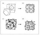
- FIG. 1 is a diagram showing an example of a three-dimensional structure generated from a plurality of polyhedra.
- FIG. 2 is a diagram showing an example of a crystal structure generated from a three-dimensional structure.
- FIG. 3 is a diagram showing another example of a crystal structure generated from a three-dimensional structure.
- FIG. 4 is a diagram showing an example of a crystal structure generated from a periodic graph.
- FIG. 5 is a block diagram showing the overall configuration including the information processing system according to the first embodiment.
- FIG. 6 is a diagram showing an example of three-dimensional structure data stored in the first storage unit.
- FIG. 7 is a diagram illustrating an example of third information stored in the second storage unit.
- FIG. 8 is a diagram showing an image displayed on the display unit in the first usage example of the first embodiment.
- FIG. 1 is a diagram showing an example of a three-dimensional structure generated from a plurality of polyhedra.
- FIG. 2 is a diagram showing an example of a crystal structure generated from
- FIG. 9 is a diagram showing an image displayed on the display unit in the first usage example of the first embodiment.
- FIG. 10 is a diagram showing an image displayed on the display unit in the second usage example of the first embodiment.
- FIG. 11 is a flowchart illustrating an example of the operation of the information processing system according to the first embodiment.
- FIG. 12 is a diagram illustrating an example of placement pattern candidates.
- FIG. 13 is a diagram showing an example of a crystal structure corresponding to an arrangement pattern candidate.
- FIG. 14 is a diagram showing another example of placement pattern candidates.
- FIG. 15 is a diagram showing another example of the crystal structure corresponding to the arrangement pattern candidate.
- FIG. 16 is a diagram illustrating an example of the arrangement of atoms in a candidate arrangement pattern.
- FIG. 17 is a sequence diagram illustrating an operation example of the information processing system, the display unit, the first storage unit, and the second storage unit according to the first embodiment.
- FIG. 18 is a diagram illustrating an example of an image displayed on the display unit according to the second embodiment.
- FIG. 19 is a flowchart illustrating an example of the operation of the information processing system according to the second embodiment.
- FIG. 20 is a block diagram showing the overall configuration including the information processing system according to the third embodiment.
- FIG. 21 is a flowchart illustrating an example of the operation of the information processing system according to the third embodiment.
- FIG. 22 is a sequence diagram illustrating an operation example of the information processing system, the display unit, the first storage unit, and the second storage unit according to the third embodiment.
- FIG. 23 is a diagram illustrating an example of the second image displayed on the display unit according to the first usage example of the third embodiment.
- FIG. 24 is a diagram illustrating an example of the third image displayed on the display unit according to the first usage example of the third embodiment.
- FIG. 25 is a diagram showing an image displayed on the display unit in the second usage example of the third embodiment.
- FIG. 26 is a diagram showing another image displayed on the display unit in the second usage example of the third embodiment.
- FIG. 27 is a diagram showing still another image displayed on the display unit in the second usage example of the third embodiment.
- FIG. 28 is a diagram showing an image displayed on the display unit when selecting another physical property in the second usage example of the third embodiment.
- FIG. 29 is a flowchart showing another example of the operation of the information processing system according to the third embodiment.
- FIG. 30 is a diagram showing an image displayed on the display unit in a modified example.
- FIG. 31 is a diagram showing an image displayed on the display unit in a modified example.
- FIG. 32 is a diagram showing a specific example of converting a periodic graph into a three-dimensional structure.
- the physical properties of a material greatly depend on how atoms are coordinated with surrounding atoms, that is, on the local coordination environment of atoms. For example, in ionic crystalline materials, cations are surrounded by a group of anions. The polyhedron formed by connecting the centers of these anions is called a coordination polyhedron.
- AgI has a face-centered cubic lattice structure (fcc type structure) with low Ag ion conductivity and a body-centered cubic lattice structure (bcc type structure) with high Ag ion conductivity.
- I ions around Ag ions are formed by filling tetrahedral and octahedral coordination polyhedra. Since Ag ions are more stable at octahedral sites, they cannot move to adjacent tetrahedral sites, making it difficult for Ag ions to conduct. On the other hand, in the bcc type structure, the I ions around the Ag ions are formed by filling a tetrahedral coordination polyhedron, and all sites are equivalent, so the Ag ions are easily conductive.
- Patent Document 1 and Patent Document 2 disclose a method of generating a new structure based on a structural feature vector.
- Patent Document 1 and Patent Document 2 do not disclose a method for generating a new crystal structure based on coordination polyhedra.
- Non-Patent Document 1 discloses a method of generating a new crystal structure based on symmetry. However, Non-Patent Document 1 does not disclose a method for generating a new crystal structure based on coordination polyhedra.
- an information processing method is an information processing method executed by a computer, which includes a step of acquiring first information regarding a plurality of polyhedra; a step of obtaining second information regarding the plurality of atoms arranged in each of the plurality of atoms; and based on the first information and the second information, each of the plurality of atoms is arranged in the three-dimensional structure in which the plurality of polyhedra are arranged.
- the method includes the steps of generating third information indicating a possible crystal structure when arranged, and outputting the generated third information.
- the three-dimensional structure may be a structure in which the plurality of polyhedra are arranged without gaps.
- the step of acquiring the first information information regarding the three-dimensional structure in which the plurality of polyhedra are arranged without gaps may be acquired as the first information.
- the information regarding the three-dimensional structure is at least one of the following: information indicating the three-dimensional structure, information indicating a numerical sequence including numbers or letters representing the three-dimensional structure, and information indicating a periodic graph representing the three-dimensional structure. It may include one.
- a crystal structure having a space-filling structure in three-dimensional space can be generated using various methods.
- the third information indicating the crystal structure may be generated using possible arrangement patterns of the plurality of atoms in the crystal structure.
- the arrangement pattern may indicate that the atoms are arranged at at least one of the vertices of each of the plurality of polyhedra and the inside of each of the plurality of polyhedra.
- step of acquiring the second information material information regarding the material containing the atoms arranged in each of the plurality of polyhedra is acquired as the second information, and in the step of generating the third information, , the third information indicating the crystal structure that the material can have may be generated based on the material information.
- element information indicating the type of each of the plurality of atoms is further acquired as the material information
- the element information indicated by the element information is further acquired.
- the third information indicating the crystal structure in which one or more types of atoms are arranged may be generated.
- composition information regarding the composition of the material is further acquired as the material information
- the step of generating the third information the crystal structure having the composition indicated by the composition information is further acquired. You may generate the third information indicating.
- a crystal structure can be generated under the constraints of the composition specified by the user, for example, so it is easy to generate the crystal structure desired by the user.
- atomic number information indicating the number of the plurality of atoms arranged in each of the plurality of polyhedra is further acquired as the material information, and the third information is generated.
- the third information indicating the crystal structure in which the atoms are arranged as many as the number of atoms indicated by the atomic number information may be generated.
- the crystal structure information indicating a basic crystal structure that is the basis of the crystal structure is acquired
- the crystal structure information is The third information may be generated indicating the crystal structure that can be obtained when the atoms are arranged in the basic crystal structure indicated by the information.
- a crystal structure can be generated under the constraints of, for example, the basic crystal structure specified by the user, so it is easy to generate the crystal structure desired by the user.
- a crystal structure can be generated under the constraints of, for example, the basic crystal structure specified by the user, so it is easy to generate the crystal structure desired by the user.
- the method may further include the step of calculating and outputting fourth information regarding the physical properties of the crystal structure indicated by the third information using at least one of first-principles calculations and machine-learning predictive models.
- the third information may be output limited to the crystal structure having predetermined physical properties based on the calculated fourth information.
- a crystal structure can be generated under the constraints of, for example, the physical properties of the crystal structure specified by the user, so it is easy to generate the crystal structure desired by the user.
- the information processing system displays a first image that receives input of first information regarding a plurality of polyhedra and second information regarding a plurality of atoms arranged in each of the plurality of polyhedra.
- a display control section that causes the display section to display a second image representing third information indicating.
- the first image includes a first input image that accepts input of the first information, and a second input image that accepts input of the second information, and the display control unit is configured to input the second input image.
- the first input image may be displayed on the display section based on the input second information.
- a program includes the steps of: acquiring first information regarding a plurality of polyhedra; acquiring second information regarding a plurality of atoms arranged in each of the plurality of polyhedra; 1 information and the second information, generating third information indicating a possible crystal structure when each of the plurality of atoms is arranged in a three-dimensional structure in which the plurality of polyhedra are arranged; and outputting the third information obtained by the computer.
- the present invention can also be implemented as a computer program that causes a computer to execute the characteristic processing included in the information processing method of the present disclosure. It goes without saying that such a computer program can be distributed via a computer-readable non-transitory recording medium such as a CD-ROM or a communication network such as the Internet.
- the three-dimensional structure is a structure in a three-dimensional space, particularly a space-filling structure in a three-dimensional space, in other words, a structure in which a plurality of polyhedra are completely filled in the three-dimensional space without gaps.
- FIG. 1 is a diagram showing an example of a three-dimensional structure generated from a plurality of polyhedra.
- FIG. 1A shows a face-centered cubic lattice structure (FCC type structure) composed of a plurality of regular tetrahedra and a plurality of regular octahedrons.
- FIG. 1B shows a body-centered cubic lattice structure (bcc type structure) composed of a plurality of regular tetrahedra.
- FIG. 1C shows a hexagonal close-packed structure (hcp type structure) composed of a plurality of regular tetrahedra and a plurality of regular octahedrons.
- FIG. 1(d) shows a perovskite structure composed of one regular octahedron and multiple cuboctahedrons. Although one cuboctahedron is shown in FIG. 1(d), in reality, a plurality of cuboctahedrons are arranged without gaps around the regular octahedron at the center.
- FIG. 1(e) shows a MgCu type 2 structure composed of a plurality of regular tetrahedra.
- the structure of an inorganic material can be regarded as a three-dimensional structure
- the technology of the present disclosure that can generate a crystal structure by inputting information on multiple polyhedra, such as the three-dimensional structure, can be applied to unknown materials. It is very effective for searching.
- FIG. 2 is a diagram showing an example of a crystal structure generated from a three-dimensional structure.
- a three-dimensional structure that is an fcc type structure shown in FIG. NaCl having a rock salt type structure shown in 2(b) is obtained.
- a three-dimensional structure that is a bcc type structure shown in FIG. 2(c) if I is placed at the vertex site and Ag is placed at the center site of the tetrahedron, AgI shown in FIG. 2(d) The type structure of AgI is obtained.
- a three-dimensional structure that is an hcp type structure shown in FIG. When holes are arranged at the center site of the face piece, ZnO having a wurtzite structure shown in FIG. 2(f) is obtained.
- FIG. 3 is a diagram showing another example of a crystal structure generated from a three-dimensional structure.
- a three-dimensional structure that is a perovskite structure shown in FIG. SrTiO 3 having a perovskite structure shown in FIG. 3(b) is obtained.
- the three-dimensional structure of the MgCu type 2 structure shown in FIG. Li 6 PS 5 Cl having an argyrodite structure shown in d) is obtained.
- the technology of the present disclosure creates a three-dimensional structure, that is, an arrangement, by arranging elements or holes at the vertex sites and center sites of each polyhedron in a three-dimensional structure based on input information on a plurality of polyhedra. Crystal structures based on topological polyhedra can be generated. Therefore, with the technology of the present disclosure, it is possible to generate a crystal structure that matches an actual crystal structure, and it is easy to generate a crystal structure with high prediction accuracy.
- a molecular structure can be expressed as a graph. That is, the molecular structure can be expressed as a graph structure in which the "atoms" constituting a compound are “nodes” and the “bonds between atoms" are “edges” connecting the nodes.
- Patent Document 2 Japanese Unexamined Patent Publication No. 2021-081769
- a periodic graph is also called a crystal net, and is a three-dimensional periodic graph.
- "three-dimensionally periodic” means that three linearly independent translations exist.
- a crystal structure can be converted into a periodic graph by defining the bonds between atoms in the crystal structure.
- a periodic graph can be uniquely converted into a crystal structure.
- a periodic graph with two independent nodes and four edges connecting them, as shown in Figure 4(a) can be interconverted with the diamond-shaped structure shown in Figure 4(b). be.
- the periodic graph is a graph that can be converted into a crystal structure that can be obtained when each of a plurality of atoms is arranged in a three-dimensional structure in which a plurality of polyhedra are arranged.
- the information processing system may be configured such that all the components are included in one computer, or may be configured as a system in which multiple components are respectively distributed among multiple computers. It's okay.
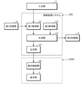
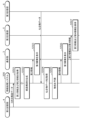
- FIG. 5 is a block diagram showing the overall configuration including the information processing system 100 according to the first embodiment.
- the information processing system 100 is configured as a computer such as a personal computer or a server, for example. That is, the information processing system 100 may be realized by cloud computing, for example.
- Embodiment 1 will be described assuming that information processing system 100 is a stationary computer.
- the information processing system 100 includes a first acquisition unit 11, a second acquisition unit 12, a generation unit 13, and an output unit 14. Further, the information processing system 100 is connected to an input section 2, a display control section 30, a display section 3, a first storage section 4, and a second storage section 5.
- the input unit 2, the display control unit 30, and the display unit 3 are configured by an information terminal used by a user, such as a smartphone, a tablet terminal, or a personal computer.
- the input unit 2, display control unit 30, and display unit 3 may be an input unit, a display control unit, and a display unit included in an information terminal used by a user.
- the input unit 2, the display control unit 30, the first storage unit 4, and the second storage unit 5 may all be connected to the information processing system 100 via a LAN (Local Area Network) or the like, or may be connected to the information processing system 100 via a LAN (Local Area Network) or the like. It may be connected to the information processing system 100 via a network.
- LAN Local Area Network
- the input unit 2, the display control unit 30, the first storage unit 4, and the second storage unit 5 may all be connected to the information processing system 100 via a LAN (Local Area Network) or the like, or may be connected to the information processing system 100 via a LAN (Local Area Network) or the like. It may be connected to the information processing system 100 via a network.
- the input unit 2 is an input interface that accepts user input, and is composed of, for example, a keyboard, a touch sensor, a touch pad, a mouse, or the like.
- the input unit 2 receives an input operation by a user, and outputs a signal corresponding to the input operation to the information processing system 100.
- the display section 3 and the input section 2 are configured independently from each other, but they may be configured integrally like a touch panel.
- the information processing system 100 does not include the display unit 3 and the input unit 2, but may include these.
- the input unit 2 receives input of first information regarding a plurality of polyhedra and input of second information regarding a plurality of atoms arranged in each of the plurality of polyhedra.
- the first information is, for example, a three-dimensional structure.
- the first information may be, for example, the type of polyhedron, the number of polyhedra, the permissible skewness, or the permissible symmetry.
- the first information has a three-dimensional structure.
- the second information may include, for example, the type of element placed at the center site and apex site of each polyhedron, the composition ratio of the elements placed at the center site and apex site of each polyhedron, or symmetry.
- a plurality of atoms includes a case where there is a plurality of one type of element, and also includes a case where there is a plurality of atoms as the total number of two or more types of elements. Note that the composition ratio and symmetry of elements are not essential information.
- the display control unit 30 causes the display unit 3 to display images and the like based on information output from the output unit 14 of the information processing system 100.
- the display unit 3 displays images and the like under the control of the display control unit 30.
- the display unit 3 is, for example, a liquid crystal display, a plasma display, an organic EL (Electro-Luminescence) display, or the like, but is not limited thereto.
- the first storage unit 4 is a recording medium for storing a three-dimensional structure database.
- the recording medium is, for example, a hard disk drive, RAM (Random Access Memory), ROM (Read Only Memory), or semiconductor memory. Note that such a recording medium may be volatile or nonvolatile.
- the three-dimensional structure database includes data regarding three-dimensional structures. Examples of three-dimensional structures recorded in the three-dimensional structure database include fcc-type structures, bcc-type structures, hcp-type structures, perovskite-type structures, and MgCu 2 -type structures.
- the three-dimensional structure data is used when the user inputs first information through the input unit 2.
- FIG. 6 is a diagram showing an example of three-dimensional structure data stored in the first storage unit 4.
- 6(a) shows a three-dimensional structure (in this case, an FCC type structure), and
- FIG. 6(b) shows the three-dimensional structure shown in FIG. 6(a) in a predetermined description format ( Here, data written in D-Symbol format is shown.
- the first storage unit 4 stores, for example, an image showing a three-dimensional structure as shown in FIG. 6(a), and data described in a predetermined description format as shown in FIG. 6(b). Saved as structural data.
- the second storage unit 5 is a recording medium for storing third information indicating the crystal structure generated by the generation unit 13.
- the recording medium is, for example, a hard disk drive, RAM (Random Access Memory), ROM (Read Only Memory), or semiconductor memory. Note that such a recording medium may be volatile or nonvolatile.
- FIG. 7 is a diagram showing an example of the third information stored in the second storage unit 5.
- (a) of FIG. 7 shows the crystal structure shown by the third information (here, the structure of NaCl), and
- (b) of FIG. 7 shows the crystal structure shown in (a) of FIG. It shows data written in a format (here, cif format).
- the second storage unit 5 stores, for example, an image showing a crystal structure as shown in FIG. 7(a) and data described in a predetermined description format as shown in FIG. Saved as .
- the third information includes, for example, an image, three-dimensional data, graph data, space group, Wyckoff label, cell size, lattice constant, angle, composition, element type, or atomic coordinates.
- the file format (extension) of the data saved in the second storage unit 5 is, for example, *. cif, *. pdb, *. ins,*. xyz, *. cc1, *. stl, *. wrl, *. pme, *. stin, *. p1, *. vasp, or *. xtl etc.
- the first acquisition unit 11 acquires first information regarding a plurality of polyhedra.
- the first acquisition unit 11 is the main entity that executes the step of acquiring first information in the information processing method of the present disclosure. Specifically, the first acquisition unit 11 acquires the first information input by the user through the input unit 2. As will be described later, the user performs an operation to input the first information while viewing the first image displayed on the display unit 3 and accepting input of the first information and the second information.
- the second acquisition unit 12 acquires second information regarding atoms arranged in each of the plurality of polyhedra.
- the second acquisition unit 12 is the main body that executes the step of acquiring second information in the information processing method of the present disclosure. Specifically, the second acquisition unit 12 acquires the second information input by the user through the input unit 2. As will be described later, the user performs an operation to input the second information while viewing the first image displayed on the display unit 3 and accepting input of the first information and the second information.
- the generation unit 13 generates each of the plurality of atoms in a three-dimensional structure in which the plurality of polyhedra are arranged, based on the first information acquired by the first acquisition unit 11 and the second information acquired by the second acquisition unit 12. Third information indicating the crystal structure that can be obtained when the crystal structure is arranged is generated.
- the generation unit 13 is the main body that executes the step of generating the third information in the information processing method of the present disclosure. In the first embodiment, the generation unit 13 executes a process of generating third information indicating the crystal structure using each possible arrangement pattern of a plurality of atoms in the crystal structure.
- the arrangement pattern indicates that atoms are arranged at at least one of the vertices of each of the plurality of polyhedra and the interior (center) of each of the plurality of polyhedra.
- the arrangement pattern of Embodiment 1 is obtained by a combination of the positions of each of a plurality of atoms that can be taken in the crystal structure. Details of the above processing will be described later.
- the output unit 14 causes the display unit 3 to display the image etc. by outputting the image etc. to the display control unit 30. Furthermore, the output unit 14 outputs the third information generated by the generation unit 13.
- the output unit 14 is the main body that executes the step of outputting the third information in the information processing method of the present disclosure. Specifically, the output unit 14 outputs the second information by displaying the second image representing the third information generated by the generation unit 13 on the display unit 3. As will be described later, the user performs an operation to select third information to be stored in the second storage unit 5 while viewing the second image displayed on the display unit 3.
- FIG. 8 and 9 are diagrams showing images displayed on the display unit 3 in the first usage example of the first embodiment.
- (a) of FIG. 8 represents an example of the first image displayed on the display unit 3.
- the first image is displayed on the display unit 3 by the output unit 14 by reading the three-dimensional structure data stored in the first storage unit 4.
- the first image includes a three-dimensional structure selection area for selecting a three-dimensional structure, a placement specification area for selecting the arrangement of atoms, and an execution icon called "Generate". There is.
- the three-dimensional structure selection area a plurality of three-dimensional structures that can be selected by the user and a plurality of selection buttons that respectively correspond to the plurality of three-dimensional structures are displayed.
- the name of each three-dimensional structure may be displayed in the three-dimensional structure selection area.
- each three-dimensional structure may be displayed as a moving image instead of a still image.
- the user selects a three-dimensional structure in the three-dimensional structure selection area.
- the first acquisition unit 11 acquires, as the first information, information regarding a three-dimensional structure in which a plurality of polyhedra are arranged without gaps.
- the generation unit 13 when the user selects the execution icon, the generation unit 13 (in the step of generating third information) generates third information indicating a crystal structure based on the selected three-dimensional structure.
- the generation unit 13 generates third information indicating the crystal structure based on the fcc type structure.
- the user has data regarding a three-dimensional structure that does not appear in the options in the three-dimensional structure selection area, it is also possible to input the three-dimensional structure.
- the 3D structure owned by the user is transferred to the first acquisition unit 11. can be obtained.
- the placement specification area displays a text box for specifying the element (atom) placed at the vertex of each polyhedron, and a text box for specifying the element (atom) placed at the center of each polyhedron. has been done.
- the user enters the desired element in each text box. Note that, for example, if the user wants to place a hole at the center of each polyhedron, the user may leave the corresponding text box blank.
- the second acquisition unit 12 obtains, as the second information, material information about the material having atoms arranged in each of the plurality of polyhedra, and more specifically, the material information about the material having atoms arranged in each of the plurality of polyhedra.
- Elemental information indicating the type of atom placed in each element will be acquired.
- the generation unit 13 in the step of generating the third information
- the generation unit 13 generates the crystal structure that the material can have based on the material information, and more specifically, the type of atoms indicated by the elemental information. generates third information indicating the crystal structure in which is arranged.
- the user inputs "Se” as the element to be placed at the vertex of the polyhedron, and "Cu” and “In” as the elements to be placed at the center of the polyhedron.
- the user may select "Se,” “Cu,” or “In” from the periodic table or preset candidate element options. Therefore, in this case, the generation unit 13 generates third information indicating a crystal structure in which “Se” is placed at the apex of the polyhedron and “Cu” or “In” is placed at the center of the polyhedron.
- FIG. 8(b) shows an example of the second image displayed on the display unit 3.
- the second image is displayed on the display unit 3 after the user selects the execution icon in the first image and the generation unit 13 generates third information indicating the crystal structure.
- the second image includes a table showing a list of crystal structures generated by the generation unit 13 and an execution icon that says "Export selected crystal structure.” In this table, from the left, a column for selecting the crystal structure to be exported, a column for displaying the identification number (ID) for each crystal structure, a column for displaying the composition of the crystal structure, and a column for displaying the symmetry of the crystal structure (here, , space group), and a column indicating the number of atoms included in the unit cell of the crystal structure.
- ID identification number
- FIGS. 9(a) to (c). show an image including an area showing the selected crystal structure and an execution icon "Save image” on the display unit 3, as shown in FIGS. 9(a) to (c). .
- FIG. 9(a) shows the image when the crystal structure with the identification number "1" is selected
- FIG. 9(b) shows the image when the crystal structure with the identification number "2" is selected
- FIG. 9C shows an image when the crystal structure with the identification number "3" is selected.
- the display unit 3 displays an image including a selection area for selecting the storage format of the crystal structure and an execution icon "save". Note that in the example shown in FIG. 9(d), the user can select either ".cif” or ".vasp", but even if it is possible to select other storage formats, good.
- third information indicating the crystal structure selected by the user is stored in the second storage unit 5.
- FIG. 10 is a diagram showing an image displayed on the display unit 3 in the second usage example of the first embodiment.
- (a) of FIG. 10 represents an example of the first image displayed on the display unit 3.
- FIG. 10(b) represents an example of the second image displayed on the display unit 3.
- the first image differs from the first usage example in that it includes a composition specification area for the user to specify a desired composition, and the maximum number of atoms in a unit cell in the crystal structure. It further includes a maximum number of atoms specification area for specifying .
- a text box for specifying the composition of the crystal structure is displayed.
- the user enters the desired composition in the text box.
- the second acquisition unit 12 in the step of acquiring the second information
- the generation unit 13 in the step of generating third information
- the generation unit 13 generates third information indicating a crystal structure having the composition indicated by the composition information.
- the user specifies "CuInSe 2 " as the composition of the crystal structure. Therefore, in this case, the generation unit 13 generates third information indicating a crystal structure having the composition "CuInSe 2 ". Therefore, in the second image, as shown in FIG. 10(b), a crystal structure having the composition "CuInSe 2 " is displayed.
- a text box for specifying the maximum number of atoms in the unit cell of the crystal structure is displayed in the maximum number of atoms specification area.
- the user enters the desired number in the text box.
- the second acquisition unit 12 (in the step of acquiring the second information) obtains, as material information, the number of atoms arranged in each of the plurality of polyhedra (here, the maximum number of atoms in the unit cell). Further, atomic number information indicating .
- the generation unit 13 (in the step of generating the third information) arranges atoms as many as the number of atoms indicated by the atomic number information (here, the atoms specified in the unit cell are third information indicating a crystal structure (in which atoms are arranged so as not to exceed the maximum value of the number) is generated.
- the generation unit 13 generates third information indicating a crystal structure in which the number of atoms in the unit cell is "16" or less. Therefore, in the second image, as shown in FIG. 10(b), a crystal structure in which the number of atoms in the unit cell is "16" or less is displayed.
- the first image includes both the composition specification area and the maximum atomic number specification area, but may include either one of them.
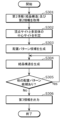
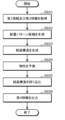
- FIG. 11 is a flowchart illustrating an example of the operation of the information processing system 100 according to the first embodiment.
- the first acquisition unit 11 acquires first information.
- the first information is input by the user using the input unit 2 while reading the three-dimensional structure data stored in the first storage unit 4 and viewing the first image displayed on the display unit 3.
- the first acquisition unit 11 acquires the information.
- the first information may be acquired by the first acquisition unit 11 by the user inputting original data using the input unit 2 without referring to the first image.
- the second acquisition unit 12 acquires second information. As described above, the second information is acquired by the second acquisition unit 12 by the user inputting (selecting) using the input unit 2 while viewing the first image displayed on the display unit 3 .
- the generation unit 13 executes a process of generating placement pattern candidates based on the acquired first information and second information.
- the generation unit 13 generates placement pattern candidates for each of a pattern in which atoms are placed at the vertex site of each polyhedron and a pattern in which atoms are placed at the center site of each polyhedron.
- atoms may be arranged randomly or atoms may be arranged efficiently based on a predetermined rule.
- a predetermined law for example, P. V. Bushlanov, V. A. Blatov and A. R.
- they are arranged so as to satisfy the symmetry of the space group.
- the generation unit 13 executes a process of generating a crystal structure for each arrangement pattern candidate. Specifically, the generation unit 13 generates a crystal structure by arranging atoms at the vertices of each polyhedron and at the center of each polyhedron according to the content of the arrangement pattern candidate.
- Step S104 The generation unit 13 determines whether there are any other placement pattern candidates for which no crystal structure has been generated. If it is determined that there are other placement pattern candidates (step S104: Yes), the generation unit 13 returns to step S103. When crystal structures have been generated for all arrangement pattern candidates (step S104: No), the processing of the generation unit 13 is completed. The information processing system 100 (information processing method) then executes step S105.
- Step S105 The output unit 14 executes a process of outputting the third information generated by the generation unit 13.
- the output unit 14 outputs the third information by displaying the second image representing the third information generated by the generation unit 13 on the display unit 3.
- the display section 3 may include a display control section 30.
- the display section 3 including the display control section 30 may be referred to as a display section 3A.
- the output unit 14 may output the third information generated by the generation unit 13 to the display unit 3A. Thereby, the display unit 3A may display the second image representing the third information. That is, the output unit 14 may display the second image representing the third information on the display unit 3A.
- FIG. 12 is a diagram illustrating an example of placement pattern candidates.
- FIG. 13 is a diagram showing an example of a crystal structure corresponding to an arrangement pattern candidate.
- FIG. 14 is a diagram showing another example of placement pattern candidates.
- FIG. 15 is a diagram showing another example of the crystal structure corresponding to the arrangement pattern candidate.
- FIG. 16 is a diagram illustrating an example of the arrangement of atoms in a candidate arrangement pattern.
- FIG. 12 shows a table showing a list of arrangement pattern candidates for an FCC type structure of a unit cell.
- the "vertex site” column in FIG. 12 indicates the elements (atoms) arranged at the vertices of each polyhedron.
- “A”, “B”, “C”, and “D” in the “Vertex Site” column correspond to “X1”, “X2”, “X3”, and “X4” in the atomic arrangement shown in FIG. 16, respectively.
- the "tetrahedral center site” column in FIG. 12 indicates an element (atom) or a hole located at the center of the tetrahedron.
- “A”, “B”, “C”, “D”, “E”, “F”, “G”, and “H” in the “tetrahedral center site” column are respectively in the atomic arrangement shown in FIG. It corresponds to “T1”, “T2”, “T3”, “T4", “T5", “T6”, “T7”, and “T8".
- the "octahedron center site” column in FIG. 12 indicates the element (atom) or hole located at the center of the octahedron.
- “A”, “B”, “C”, and “D” in the “octahedral center site” column correspond to “O1”, “O2”, “O3”, and “O4” in the atomic arrangement shown in Figure 16, respectively. handle.
- the “composition” column in FIG. 12 indicates the composition of the crystal structure.
- FIG. 13 shows a crystal structure corresponding to "arrangement pattern candidate 1" in FIG. 12. That is, in (a) of FIG. 13, the composition is "CuInSe 2 ", “Se” is placed at the vertex of each polyhedron, “Cu”, “In”, or a hole is placed at the center of each tetrahedron, and each 8 It shows a crystal structure in which a hole is placed in the center of a hedron.
- FIG. 13(b) shows a crystal structure corresponding to "arrangement pattern candidate 4" in FIG. 12. That is, in FIG.
- the composition is "CuInSe", with “Se” at the apex of each polyhedron, “Cu” or “In” at the center of each tetrahedron, and an empty space at the center of each octahedron.
- FIG. 13(c) shows a crystal structure corresponding to "arrangement pattern candidate 8" in FIG. 12. That is, in FIG. 13(c), the composition is "CuInSe --2 ", with “Se” at the apex of each polyhedron, a hole at the center of each tetrahedron, and "Cu” at the center of each octahedron. Or, it shows a crystal structure in which "In” is arranged.
- FIG. 14 shows a table showing a list of layout pattern candidates for a 1 ⁇ 1 ⁇ 2 supercell fcc type structure.
- the "vertex site” column and the “octahedral center site” column are omitted, and a part of the “tetrahedral center site” column is omitted.
- FIG. 15 shows a crystal structure corresponding to "arrangement pattern candidate 1" in FIG. 14. That is, in FIG. 15, the composition is "CuInSe 2 ", with “Se” at the apex of each polyhedron, "Cu", "In”, or a hole at the center of each tetrahedron, and a hole at the center of each octahedron. Shows a crystal structure with holes arranged.
- FIG. 17 is a sequence diagram showing an example of the operation of the information processing system 100, the display section 3, the first storage section 4, and the second storage section 5 according to the first embodiment.
- the first acquisition unit 11 of the information processing system 100 acquires first information.
- the first information is input (selected) by the user using the input unit 2 while reading the three-dimensional structure data stored in the first storage unit 4 and viewing the first image displayed on the display unit 3.
- the data is acquired by the first acquisition unit 11.
- the second acquisition unit 12 of the information processing system 100 acquires second information.
- the second information is acquired by the second acquisition unit 12 by the user inputting (selecting) using the input unit 2 while viewing the first image displayed on the display unit 3 .
- Step S202 The generation unit 13 executes a process of generating placement pattern candidates based on the acquired first information and second information.
- Step S203 The generation unit 13 executes a process of generating a crystal structure for each arrangement pattern candidate.
- the display unit 3 displays a second image representing third information output from the output unit 14 of the information processing system 100.
- the display section 3 may include a display control section 30.
- the display section 3 including the display control section 30 may be referred to as a display section 3A.
- the output unit 14 may cause the display unit 3A to display a second image representing the third information.
- Step S205 When the user selects a crystal structure to save while viewing the second image displayed on the display unit 3, the information processing system 100 provides the second storage unit 5 with third information indicating the selected crystal structure. Thereby, the second storage unit 5 stores the third information indicating the crystal structure selected by the user.
- the first embodiment information on a plurality of polyhedra is input, and in a three-dimensional structure based on the input information on the plurality of polyhedra, elements or holes are placed at the vertex sites and center sites of each polyhedron.
- a three-dimensional structure that is, a crystal structure based on a coordination polyhedron. Therefore, in the first embodiment, it is possible to generate a crystal structure that matches the actual crystal structure, and it is easy to generate a crystal structure with high prediction accuracy.
- the information processing system according to the second embodiment is different from the information processing system according to the first embodiment in that the first acquisition unit 11 acquires crystal structure information indicating a basic crystal structure that is the basis of the crystal structure as the first information. It is different from 100. Further, the information processing system according to the second embodiment is similar to the second embodiment in that the generation unit 13 generates third information indicating a possible crystal structure when atoms are arranged in the basic crystal structure indicated by the crystal structure information.
- the information processing system 100 according to No. 1 is different from the information processing system 100 according to No. 1.
- the information processing system according to the second embodiment like the information processing system 100 according to the first embodiment, includes a first acquisition section 11, a second acquisition section 12, a generation section 13, and an output section 14. , and the configuration is common, so a description of these will be omitted.
- FIG. 18 is a diagram showing an example of an image displayed on the display unit 3 according to the second embodiment.
- FIG. 18 shows an example of the first image displayed on the display unit 3.
- the first image is a crystal structure for selecting a basic crystal structure that is the basis of the crystal structure generated by the generation unit 13, instead of a three-dimensional structure selection area. Contains a selection area.
- the crystal structure selection area a plurality of basic crystal structures that can be selected by the user and a plurality of selection buttons respectively corresponding to the plurality of basic crystal structures are displayed.
- the name of each basic crystal structure may be displayed in the crystal structure selection area.
- each basic crystal structure may be displayed as a moving image instead of a still image.
- the user selects a basic crystal structure in the crystal structure selection area.
- the first acquisition unit 11 acquires, as the first information, crystal structure information indicating a basic crystal structure that is the basis of the crystal structure.
- the generation unit 13 in the step of generating third information
- the generation unit 13 generates third information indicating a crystal structure based on the selected basic crystal structure.
- the user can cause the first acquisition unit 11 to acquire the basic crystal structure owned by the user. .
- FIG. 19 is a flowchart illustrating an example of the operation of the information processing system according to the second embodiment.
- the first acquisition unit 11 acquires first information.
- the first information is crystal structure information as described above, and is input (selected) by the user using the input unit 2 while viewing the first image displayed on the display unit 3. Then, it is acquired by the first acquisition unit 11.
- the second acquisition unit 12 acquires second information. The second information is the same as in the first embodiment.
- Step S302 The generation unit 13 determines the vertex site of each polyhedron and the center site of each polyhedron in the basic crystal structure based on the acquired first information. In other words, the generation unit 13 (in the step of generating the third information) determines the positions of the vertices of each of the plurality of polyhedra in which atoms are arranged, and the positions of the vertices of the plurality of polyhedra, based on the basic crystal structure indicated by the crystal structure information. Determine the internal (center) position of each.
- Step S303 Similar to the first embodiment, the generation unit 13 executes a process of generating placement pattern candidates based on the acquired first information and second information.
- Step S304 Similar to the first embodiment, the generation unit 13 executes a process of generating a crystal structure for each arrangement pattern candidate.
- Step S305 Similar to the first embodiment, the generation unit 13 determines whether there are any other placement pattern candidates for which no crystal structure has been generated. If it is determined that there are other placement pattern candidates (step S305: Yes), the generation unit 13 returns to step S304. When crystal structures have been generated for all arrangement pattern candidates (step S305: No), the processing of the generation unit 13 is completed. The information processing system (information processing method) then executes step S306.
- Step S306 The output unit 14 executes the process of outputting the third information generated by the generation unit 13, as in the first embodiment.
- a crystal structure can be generated by inputting information on a basic crystal structure that is the basis of the crystal structure to be generated. Therefore, in the second embodiment, as in the first embodiment, it is possible to generate a crystal structure that conforms to the actual crystal structure, and it is easy to generate a crystal structure with high prediction accuracy.
- Embodiment 3 an information processing system 200 (information processing method or program) according to Embodiment 3 of the present disclosure will be described in detail using the drawings.
- the information processing system 200 according to the third embodiment differs from the information processing system 100 according to the first embodiment in that the generation unit 13 calculates and outputs fourth information regarding the physical properties of the crystal structure generated.
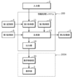
- FIG. 20 is a block diagram showing the overall configuration including an information processing system 200 according to the third embodiment.
- a third storage unit 6 is further connected to the information processing system 200 according to the second embodiment.
- the generation unit 13 has a function of calculating fourth information regarding the physical properties of the generated crystal structure. Note that a description of the configuration common to the information processing system 100 according to the first embodiment will be omitted.
- the third storage unit 6 is a recording medium for storing a compound database regarding physical property values (including predicted values) of existing materials.
- the recording medium is, for example, a hard disk drive, RAM (Random Access Memory), ROM (Read Only Memory), or semiconductor memory. Note that such a recording medium may be volatile or nonvolatile.
- the generation unit 13 predicts the physical properties of the crystal structure based on the generated crystal structure and the compound data read from the third storage unit 6.
- physical properties include indicators of synthesis possibility such as thermodynamic convex hull energy, optical properties such as band gap, electronic properties such as carrier mobility, dielectric properties such as relative permittivity, and ion conduction. It may include transport physical properties such as power, electrochemical properties such as potential window, etc.
- the physical properties include information regarding the synthesis of the crystal structure. Information regarding synthesis may include candidates for raw materials used in synthesizing the crystal structure, conditions for synthesis, and the like.
- the physical properties of the crystal structure can be calculated using, for example, first-principles calculations or machine-learned predictive models.
- the thermodynamic convex hull energy or bandgap of a crystal structure can be calculated using first principles calculations.
- the thermodynamic convex hull energy or band gap of a crystal structure can be calculated (estimated) using a prediction model.
- the prediction model is constructed by a graph neural network that receives the graph structure as input.
- the graph neural network is, for example, CGCNN (Crystal Graph Convolutional Neural Network) or MEGNet (Material Graph Network).
- the prediction model is configured by MEGNet.
- MEGNet is a graph neural network that uses not only nodes (nodes/vertices) and edges (branches/sides) as feature quantities, but also global state quantities representing the characteristics of the entire target system as feature quantities.
- the prediction model is machine-trained to output the total energy of an arbitrary crystal structure in response to an input crystal structure.
- the learning data set includes a crystal structure as input data and total energy corresponding to the crystal structure as correct data.
- FIG. 21 is a flowchart illustrating an example of the operation of the information processing system 200 according to the third embodiment.
- the first acquisition unit 11 acquires first information.
- the first information is obtained by reading the three-dimensional structure data stored in the first storage unit 4 and viewing the first image displayed on the display unit 3, as in the first embodiment.
- the first acquisition unit 11 acquires the information.
- the second acquisition unit 12 acquires second information. The second information is the same as in the first embodiment.
- Step S402 Similar to the first embodiment, the generation unit 13 executes a process of generating placement pattern candidates based on the acquired first information and second information.
- Step S403 Similar to the first embodiment, the generation unit 13 executes a process of generating a crystal structure for each arrangement pattern candidate. Here, in step S403, the generation unit 13 generates crystal structures for all arrangement pattern candidates.
- Step S404 The generation unit 13 executes a process of predicting the physical properties of the crystal structure based on the generated crystal structure and the compound data read from the third storage unit 6. For example, the generation unit 13 calculates thermodynamic convex hull energy as a physical property of the crystal structure. For example, when the composition of the crystal structure is "CuInSe 2 ", the thermodynamic convex hull energy is expressed by the following formula.
- thermodynamic convex hull energy indicates the thermodynamic convex hull energy of the crystal structure "A”
- Etot(A) indicates the total energy of the crystal structure "A”.
- the total energy of a crystal structure can be calculated using first-principles calculations or a machine-learned prediction model.
- thermodynamic convex hull energy can be expressed, for example, in a paper by Wenhao et al. y.” Science advances 2.11 (2016): e1600225.) It has been suggested that synthesis is possible as long as the voltage is 0.1 eV or less.
- the thermodynamic convex hull energy is an index of the synthesis possibility of a crystal structure.
- Step S405 The output unit 14 executes a process of outputting the fourth information generated by the generation unit 13.
- the output unit 14 outputs the fourth information by displaying the third image representing the fourth information generated by the generation unit 13 on the display unit 3.
- FIG. 22 is a sequence diagram showing an example of the operation of the information processing system 200, the display unit 3, the first storage unit 4, and the second storage unit 5 according to the third embodiment.
- Step S501 The first acquisition unit 11 of the information processing system 200 acquires first information.
- the first information is input (selected) by the user using the input unit 2 while reading the three-dimensional structure data stored in the first storage unit 4 and viewing the first image displayed on the display unit 3.
- the data is acquired by the first acquisition unit 11.
- the second acquisition unit 12 of the information processing system 200 acquires second information.
- the second information is acquired by the second acquisition unit 12 by the user inputting (selecting) using the input unit 2 while viewing the first image displayed on the display unit 3 .
- Step S502 The generation unit 13 of the information processing system 200 executes a process of generating a crystal structure for each arrangement pattern candidate. Note that between step S501 and step S502, the same processing as step S202 (see FIG. 17) is executed.
- the display unit 3 displays a second image representing third information output from the output unit 14 of the information processing system 200.
- the display section 3 may include a display control section 30.
- the display section 3 including the display control section 30 may be referred to as a display section 3A.
- the output unit 14 may cause the display unit 3A to display a second image representing the third information.
- Step S504 The first acquisition unit 11 (or second acquisition unit 12) of the information processing system 200 reads compound data stored in the third storage unit 6 and acquires the compound data.
- Step S505 The generation unit 13 of the information processing system 200 predicts the physical properties of the crystal structure based on the generated crystal structure and the compound data read from the third storage unit 6.
- Step S506 The display unit 3 displays a third image representing fourth information output from the output unit 14 of the information processing system 200.
- the output unit 14 may cause the display unit 3A to display a third image representing the fourth information.
- Step S507 When the user selects a crystal structure to be saved while viewing the third image displayed on the display unit 3, the information processing system 200 displays third information indicating the selected crystal structure and third information corresponding to the selected crystal structure. 4 information to the second storage unit 5. Thereby, the second storage unit 5 stores third information indicating the crystal structure selected by the user and fourth information corresponding to the selected crystal structure.
- FIG. 23 is a diagram showing an example of the second image displayed on the display unit 3 in the first usage example of the third embodiment.
- the second image is displayed on the display unit 3 after the user selects the execution icon in the first image and the generation unit 13 generates third information indicating the crystal structure.
- the second image includes a table showing a list of crystal structures generated by the generation unit 13 and an execution icon "Export selected crystal structure".
- the second image further includes a physical property selection area for selecting the physical property of the crystal structure to be predicted, and a prediction execution icon labeled "Predict physical property.”
- the physical property selection area physical properties of the crystal structure that can be selected by the user are displayed.
- the user can select one of "convex hull energy" and "bandgap," but other than crystal structure
- the physical properties may be selectable.
- the user wants to predict the physical properties of a crystal structure, he selects the physical properties of the crystal structure that he wants to predict in the physical property selection area, and selects the prediction execution icon. Thereby, the generation unit 13 executes a process of predicting the physical properties of the crystal structure.
- the user thinks that it is not necessary to predict the physical properties of the crystal structure, he selects the crystal structure he wants to save and selects the execution icon. In this case, the user can confirm the selected crystal structure and then save it in the second storage unit 5 without obtaining the prediction result of the physical properties of the crystal structure.
- FIG. 24 is a diagram showing an example of the third image displayed on the display unit 3 according to the first usage example of the third embodiment.
- the third image is displayed on the display unit 3 after the user selects the prediction execution icon in the second image and the generation unit 13 generates fourth information regarding the physical properties of the crystal structure.
- the third image includes a table showing a list of the crystal structures generated by the generation unit 13 and physical properties of the crystal structures predicted by the generation unit 13, and an execution icon “Export selected crystal structure”.
- the third image shown in FIG. 24(a) shows an image when the user selects "convex hull energy" in the physical property selection area.
- a "synthesizability index” column is included in the table, and this column indicates the thermodynamic convex hull energy of the crystal structure. Note that the smaller the thermodynamic convex hull energy of the crystal structure, the higher the possibility of synthesis.
- the third image shown in FIG. 24(b) shows an image when the user selects "bandgap" in the physical property selection area.
- the table includes a "Bandgap" column, which indicates the bandgap of the crystal structure.
- the user selects the crystal structure that he or she wants to save and selects the execution icon. Thereby, after confirming the selected crystal structure, the user can save the third information indicating the selected crystal structure and the fourth information regarding the physical properties of the selected crystal structure in the second storage unit 5. .
- FIG. 25 is a diagram showing an image displayed on the display unit 3 in the second usage example of the third embodiment.
- FIG. 25A shows a part of the first image that is displayed next on the display unit 3 when the user selects the physical property of the crystal structure in the physical property selection area in the first image.
- the user has selected "convex hull energy" as the physical property of the crystal structure.
- an execution icon "Please select threshold and condition", a text box for specifying the threshold, and a pull-down menu for specifying the condition are displayed.
- the generation unit 13 narrows down the generated crystal structures to those having a thermodynamic convex hull energy of 100 meV/atm or less and makes a prediction. That is, the generation unit 13 (in the step of generating the third information) determines a predetermined physical property (here, thermodynamic convex hull energy) based on the calculated fourth information (here, thermodynamic convex hull energy). 100 meV/atm or less) to generate the third information.
- a predetermined physical property here, thermodynamic convex hull energy
- FIG. 25(b) is a diagram showing an example of the third image displayed on the display unit 3.
- the third image further includes a "raw material candidate" column indicating raw material candidates for generating the crystal structure in the table.
- the raw material candidates shown in the "Raw Material Candidate" column merely indicate raw materials that have the possibility of generating a crystal structure, and it does not necessarily mean that a corresponding crystal structure can be generated if the raw materials are synthesized.
- FIG. 25(c) is a diagram showing an example of the third image displayed on the display section 3.
- the image shown in FIG. 25(c) may be displayed on the display unit 3 at the same time as the image shown in FIG. 25(b), or may be displayed on the display unit 3 separately from the image shown in FIG. 25(b). may be done.
- the third image shown in FIG. 25(c) includes a mapping area.
- the mapping area shows the mapping results showing the number of crystal structures that meet the specified threshold and conditions, the multiple elements (atoms) that make up the crystal structure are represented at the vertices, and the multiple compounds made of these multiple elements are represented on the line. A map and will be displayed.
- compositions of the crystal structure and the composition representing a phase thermodynamically coexisting with the crystal structure are displayed. Furthermore, in the map, compositions that have zero thermodynamic convex hull energy, that is, thermodynamically stable phases, are connected by straight lines.
- the crystal structure having the composition "CuInSe 2 " is located on the line. Therefore, the user can understand that the possibility of synthesizing the crystal structure is relatively high.
- the crystal structure having the composition "CuInSe” is not located on the line. Therefore, the user can understand that the possibility of synthesizing the crystal structure is relatively low.
- FIG. 26 is a diagram showing another image displayed on the display unit 3 in the second usage example of the third embodiment.
- the image shown in FIG. 26 is displayed on the display unit 3 when the user selects the composition of the crystal structure on the map in the image shown in FIG. (here, thermodynamic convex hull energy).
- the example shown in FIG. 26 shows an image when the user selects the crystal structure composition "CuInSe" on the map.
- FIG. 27 is a diagram showing still another image displayed on the display section 3 in the second usage example of the third embodiment.
- the image shown in Figure 27(a) is similar to the image shown in Figure 25(a), with an execution icon that says ⁇ Please select a threshold and conditions'', a text box for specifying a threshold, and a text box for specifying conditions. Includes a pull-down menu for specifying.
- the user inputs "50" into the text box and selects "less than” from the pull-down menu.
- the generation unit 13 narrows down the generated crystal structures to those having a thermodynamic convex hull energy of 50 meV/atm or less and makes a prediction.
- the image shown in FIG. 27(b) is similar to the image shown in FIG. 25(b), and shows the processing result by the generation unit 13 under the threshold and conditions shown in FIG. 27(a).
- the image shown in FIG. 27(c) is similar to the image shown in FIG. 25(c), and shows the processing result by the generation unit 13 under the threshold value and conditions shown in FIG. 27(a).
- FIG. 28 is a diagram showing an image displayed on the display unit 3 when selecting another physical property in the second usage example of the third embodiment.
- the user selects "bandgap" as the physical property of the crystal structure, enters "2.0" in the text box, and selects "less than” in the pull-down menu. ing.
- the generation unit 13 narrows down the generated crystal structures to those with a band gap of 2.0 eV or less and makes a prediction.
- FIG. 28(b) is an image similar to the image shown in FIG. 25(b), and shows the processing result by the generation unit 13 under the threshold value and conditions shown in FIG. 28(a).
- the third image includes a "bandgap" column instead of a "convex hull energy” column.
- FIG. 28(c) is an image similar to the image shown in FIG. 25(c), and shows the processing result by the generation unit 13 under the threshold value and conditions shown in FIG. 28(a).
- a map representing the size of the band gap with shading is displayed in the mapping area of the third image.
- FIG. 29 is a flowchart showing another example of the operation of the information processing system according to the third embodiment.
- Step S601 The first acquisition unit 11 acquires first information. Further, the second acquisition unit 12 acquires second information. Step S601 is similar to step S401.
- Step S602 Similar to step S402, the generation unit 13 executes a process of generating placement pattern candidates based on the acquired first information and second information.
- Step S603 Similar to step S403, the generation unit 13 executes a process of generating crystal structures for all arrangement pattern candidates.
- Step S604 The generation unit 13 executes a process of predicting the physical properties of the crystal structure based on the generated crystal structure and the compound data read from the third storage unit 6, as in step S404.
- the generation unit 13 generates third information by restricting the crystal structure to crystal structures having predetermined physical properties, in other words, by narrowing down to crystal structures having predetermined physical properties.
- the predetermined physical properties are thresholds and conditions specified by the user (for example, thermodynamic convex hull energy is 100 meV/atm or less).
- Step S606 The output unit 14 executes a process of outputting the fourth information generated by the generation unit 13, similarly to step S405.
- the fourth information includes the crystal structure narrowed down in step S605.
- the third embodiment it is possible not only to generate a crystal structure but also to predict and output the physical properties of the generated crystal structure. Therefore, in the third embodiment, the user can efficiently search for unknown materials by referring to the physical properties of the generated crystal structure.
- the first image is displayed on the display unit 3 in the order of the image shown in FIG. 30(a), the image shown in FIG. 30(b), and the image shown in FIG. 30(c). May be displayed.
- FIG. 30 is a diagram showing an image displayed on the display unit 3 in a modified example.
- FIG. 30(a) shows an example of the first image displayed first on the display unit 3.
- the first image shown in FIG. 30(a) includes an element selection area for selecting an element and an execution icon "Next".
- a periodic table is displayed in the element selection area.
- the user selects an element (atom) contained in a desired material in the element selection area.
- the element becomes the element arranged at the center of the polyhedron.
- the second acquisition unit 12 acquires material information regarding the composition of the material (here, atoms contained in the material) as the second information. I will get it.
- FIG. 30(b) shows an example of the first image displayed second on the display unit 3.
- the first image shown in FIG. 30(b) is displayed on the display unit 3 when the user selects the execution icon in the first image shown in FIG. 30(a).
- an arrangement designation area for specifying the arrangement of elements (atoms) included in the material and an execution icon "Next" are displayed.
- a table showing the number of each element in the polyhedron and the position (vertex or center) of each element in the polyhedron is displayed.
- the second acquisition unit 12 acquires second information regarding the arrangement of elements (atoms) arranged in each of the plurality of polyhedra.
- FIG. 30(c) shows an example of the first image displayed third on the display unit 3.
- the first image shown in FIG. 30 is displayed on the display unit 3 when the user selects the execution icon in the first image shown in FIG. 30(b).
- the first image shown in FIG. 30(c) includes a three-dimensional structure selection area, similar to the first image shown in FIG. 8 of the first embodiment.
- FIG. 31 is a diagram showing an image displayed on the display unit 3 in a modified example.
- FIG. 31 is a second image that is displayed on the display unit 3 after the generation unit 13 generates the third information indicating the crystal structure.
- the second image includes a list of crystal structures generated by the generation unit 13 and an execution icon that says "Export selected crystal structure.”
- the information processing system displays the first to third images on the display unit 3, but the present invention is not limited to this.
- the information processing system may output information included in the first to third images without displaying them on the display unit 3.
- the first acquisition unit 11 of the information processing system acquires the first information input by the user through the input unit 2, but the invention is not limited to this.
- the first acquisition unit 11 may acquire the first information by reading information stored in the first storage unit 4 without receiving input from the user.
- the information processing system generates the crystal structure using the three-dimensional structure or the basic crystal structure as the first information, but the information processing system is not limited to this.
- the information processing system may generate a crystal structure using a plurality of polyhedra as first information.
- the generation unit 13 generates a three-dimensional structure from a plurality of polyhedra as the first information, and then executes a process of generating a crystal structure.
- a method for generating a three-dimensional structure from multiple polyhedra can be realized by expressing the three-dimensional structure as a sequence of numbers or a graph.
- the "number sequence” here includes not only numbers but also letters such as alphabets in which numbers are replaced.
- Inorganic genes include, for example, K.
- CRYSTAL-SELFIES which is an application of SELFIE proposed by Krenn et al., which can express a molecular structure using a string of alphabets, to a three-dimensional structure.
- an inorganic gene is, for example, a multivesicular code that can be converted into a three-dimensional structure.
- the multivesicular body code of type A zeolite (LTA) structure is represented by the numerical sequence "OHG 4 (HG) 4 H”.
- “O”, “H”, and “G” are called a polyhedron code, which is a sequence determined from the input polyhedron.
- “O” means a truncated octahedron, and is represented by the sequence "46 4 (46) 4 4".
- “H” means a cube, and is represented by the numerical sequence "46”.
- G means a truncated cuboctahedron, and is represented by the numerical sequence "6 (48) 3 (64) 6 (84) 3 6".
- this multivesicular body code By changing the arrangement of this multivesicular body code, another three-dimensional structure composed of the same plurality of polyhedra can be generated. Furthermore, by changing the polyhedron code, any polyhedron can be expressed. In this way, by using inorganic genes typified by multivesicular body codes, it becomes possible to comprehensively generate three-dimensional structures from information on multiple polyhedra.
- the method of generating a three-dimensional structure from a plurality of polyhedra can also be realized by expressing the three-dimensional structure as a periodic graph.
- a polyhedron can be converted into a polyhedron graph by connecting each vertex site of the polyhedron to the center site.
- a periodic graph can be generated by combining each vertex node in a plurality of converted polyhedral graphs. For example, by using the method shown in the above-mentioned Kotani-Sunada theory (Kotani-Sunada, 2000, Trans. Amer. Mat), it is possible to convert the periodic graph into a three-dimensional structure.
- FIG. 32 is a diagram showing a specific example of converting a periodic graph into a three-dimensional structure.
- the three-dimensional structure (fcc type structure) shown in FIG. 32(b) is generated by converting the periodic graph shown in FIG. 32(a). In this way, by using a periodic graph, it is possible to comprehensively generate a three-dimensional structure from information on a plurality of polyhedra.
- the first storage section 4 and the second storage section 5 are realized by mutually different recording media, but the present invention is not limited to this.
- the first storage unit 4 and the second storage unit 5 may be realized by the same recording medium.
- the first storage section 4, the second storage section 5, and the third storage section 6 are realized by mutually different recording media, but the present invention is not limited to this.
- the first storage section 4, the second storage section 5, and the third storage section 6 may be realized by the same recording medium.
- the first acquisition unit 11 and the second acquisition unit 12 are different acquisition units, but they may be realized by the same acquisition unit.
- the information processing system 100, 200 is composed of the first acquisition section 11, the second acquisition section 12, the generation section 13, and the output section 14.
- the information processing system 100 may include a display control section 30 and a display section 3, as indicated by "100A" in FIG.
- the information processing system 200 may similarly include a display control section 30 and a display section 3.
- the first image is configured to accept input of the first information and the second information as one image, but the image that accepts the input of the first information and the second information
- the images may be displayed on the display unit 3 in order.
- the former image may be displayed on the display section 3 first, or the latter image may be displayed on the display section 3 first.
- the first image includes a first input image (image shown in FIG. 30(c)) that accepts input of first information, and a second input image (image shown in (c) of FIG. 30) that accepts input of second information. (images shown in FIGS. 30(a) and 30(b)).
- the display control unit 30 displays the second input image on the display unit 3, and displays the first input image on the display unit 3 based on the input second information. It turns out.
- each component may be configured with dedicated hardware, or may be realized by executing a software program suitable for each component.
- Each component may be realized by a program execution unit such as a CPU (Central Processing Unit) or a processor reading and executing a software program recorded on a recording medium such as a hard disk or a semiconductor memory.
- a program execution unit such as a CPU (Central Processing Unit) or a processor reading and executing a software program recorded on a recording medium such as a hard disk or a semiconductor memory.
- At least one of the above devices is specifically a computer system consisting of a microprocessor, ROM (Read Only Memory), RAM (Random Access Memory), hard disk unit, display unit, keyboard, mouse, etc. be.
- a computer program is stored in the RAM or hard disk unit.
- the at least one device described above achieves its functions by the microprocessor operating according to a computer program.
- a computer program is configured by combining a plurality of instruction codes indicating instructions to a computer in order to achieve a predetermined function.
- a part or all of the components constituting at least one of the above devices may be composed of one system LSI (Large Scale Integration).
- a system LSI is a super-multifunctional LSI manufactured by integrating multiple components onto a single chip, and specifically, it is a computer system that includes a microprocessor, ROM, RAM, etc. .
- a computer program is stored in the RAM. The system LSI achieves its functions by the microprocessor operating according to a computer program.
- An IC card or module is a computer system consisting of a microprocessor, ROM, RAM, etc.
- the IC card or module may include the above-mentioned super multifunctional LSI.
- An IC card or module achieves its functions by a microprocessor operating according to a computer program. This IC card or this module may be tamper resistant.
- the present disclosure may be the method described above. Furthermore, it may be a computer program that implements these methods using a computer, or it may be a digital signal formed from a computer program.
- the present disclosure also provides a method for storing computer programs or digital signals on computer-readable recording media, such as flexible disks, hard disks, CD (Compact Disc)-ROMs, DVDs, DVD-ROMs, DVD-RAMs, and BDs (Blu-rays). (registered trademark) Disc), semiconductor memory, etc. Further, it may be a digital signal recorded on these recording media.
- computer-readable recording media such as flexible disks, hard disks, CD (Compact Disc)-ROMs, DVDs, DVD-ROMs, DVD-RAMs, and BDs (Blu-rays). (registered trademark) Disc), semiconductor memory, etc. Further, it may be a digital signal recorded on these recording media.
- the present disclosure may transmit a computer program or a digital signal via a telecommunication line, a wireless or wired communication line, a network typified by the Internet, data broadcasting, or the like.
- program or digital signal may be implemented by another independent computer system by recording the program or digital signal on a recording medium and transferring it, or by transferring the program or digital signal via a network or the like.
- the present disclosure is useful when searching for unknown materials.
- First acquisition unit 12
- Second acquisition unit 13
- Generation unit 14
- Output unit 2
- Display unit 30
- Display control unit 4
- First storage unit 5
- Second storage unit 6 Third storage unit 100, 200 Information processing system 100A, 200A information processing system
Abstract
情報処理方法は、コンピュータが実行する情報処理方法であって、複数の多面体に関する第1情報を取得するステップ(S101)と、複数の多面体の各々に配置される複数の原子に関する第2情報を取得するステップ(S101)と、第1情報及び第2情報に基づいて、複数の多面体を配置させた3次元構造に複数の原子の各々が配置された場合にとり得る結晶構造を示す第3情報を生成するステップ(S102~S104)と、生成した第3情報を出力するステップ(S105)と、を含む。
Description
本開示は、結晶構造を生成する技術等に関する。
実験報告がない組成において高機能材料を探索するために、結晶構造を予測することは重要である。特に、電子伝導、イオン伝導、熱伝導、そして合成可能性のような結晶構造の物性が支配的な材料の物性をターゲットとする場合において、結晶構造の予測精度がスクリーニングの結果を左右する。
特許文献1及び特許文献2は、構造の特徴ベクトルに基づき分子構造を生成する方法を開示している。
非特許文献1は、対称性に基づいて構造を生成する方法を開示している。
S. Fredericks, K. Parrish, D. Sayre et al. Computer Physics Communications 261 (2021) 107810
本開示は、予測精度の高い結晶構造を生成しやすい情報処理方法等を提供する。
本開示の一態様に係る情報処理方法は、コンピュータが実行する情報処理方法であって、複数の多面体に関する第1情報を取得するステップと、前記複数の多面体の各々に配置される複数の原子に関する第2情報を取得するステップと、前記第1情報及び前記第2情報に基づいて、前記複数の多面体を配置させた3次元構造に前記複数の原子の各々が配置された場合にとり得る結晶構造を示す第3情報を生成するステップと、生成した前記第3情報を出力するステップと、を含む。
本開示によれば、予測精度の高い結晶構造を生成しやすい。
(本開示に至った知見)
電子伝導、イオン伝導、又は熱伝導等の材料の物性は、原子が周囲の原子とどのように配位しているか、つまり原子の局所的な配位環境に大きく依存する。例えば、イオン性結晶材料の場合、陽イオンは一群の陰イオンによって取り囲まれている。この陰イオンの中心を結んでできる多面体を配位多面体と呼ぶ。例えば、AgIは、Agイオン伝導性が低い面心立方格子構造(fcc型の構造)と、Agイオン伝導性が高い体心立方格子構造(bcc型の構造)と、をとる。fcc型の構造では、Agイオン周りのIイオンは、四面体と八面体の配位多面体を充填して構成される。Agイオンは、八面体サイトの方が安定となるため、隣の四面体サイトに移動できず、Agイオンは伝導しにくい。一方、bcc型の構造では、Agイオン周りのIイオンは、四面体の配位多面体を充填して構成され、全てのサイトが等価であるため、Agイオンは伝導しやすい。
電子伝導、イオン伝導、又は熱伝導等の材料の物性は、原子が周囲の原子とどのように配位しているか、つまり原子の局所的な配位環境に大きく依存する。例えば、イオン性結晶材料の場合、陽イオンは一群の陰イオンによって取り囲まれている。この陰イオンの中心を結んでできる多面体を配位多面体と呼ぶ。例えば、AgIは、Agイオン伝導性が低い面心立方格子構造(fcc型の構造)と、Agイオン伝導性が高い体心立方格子構造(bcc型の構造)と、をとる。fcc型の構造では、Agイオン周りのIイオンは、四面体と八面体の配位多面体を充填して構成される。Agイオンは、八面体サイトの方が安定となるため、隣の四面体サイトに移動できず、Agイオンは伝導しにくい。一方、bcc型の構造では、Agイオン周りのIイオンは、四面体の配位多面体を充填して構成され、全てのサイトが等価であるため、Agイオンは伝導しやすい。
このように、充填される配位多面体の種類により発現する材料の物性が変わる。そのため、狙いの物性を有する配位多面体を指定して結晶構造を生成することができれば、効率的な未知の材料の探索が可能となる。すなわち、これまで報告のない結晶構造を生成することができ、未知の高機能性材料を見出すことができる。
しかしながら、配位多面体を入力とした結晶構造を生成する方法はこれまでなく、狙いの高機能性を有する未知の材料を見つけるのは困難である。
例えば、特許文献1及び特許文献2は、構造特徴ベクトルに基づき新たな構造を生成する方法を開示している。しかしながら、特許文献1及び特許文献2には、配位多面体に基づき新たな結晶構造を生成する方法は開示されていない。
また、非特許文献1は、対称性に基づき新たな結晶構造を生成する方法を開示している。しかしながら、非特許文献1には、配位多面体に基づき新たな結晶構造を生成する方法は開示されていない。
上記の課題を解決するために、本開示の一態様に係る情報処理方法は、コンピュータが実行する情報処理方法であって、複数の多面体に関する第1情報を取得するステップと、前記複数の多面体の各々に配置される複数の原子に関する第2情報を取得するステップと、前記第1情報及び前記第2情報に基づいて、前記複数の多面体を配置させた3次元構造に前記複数の原子の各々が配置された場合にとり得る結晶構造を示す第3情報を生成するステップと、生成した前記第3情報を出力するステップと、を含む。
これにより、予測精度の高い結晶構造を生成しやすい。
また、例えば、前記3次元構造は、前記複数の多面体が隙間なく配置された構造であってもよい。
これにより、3次元空間での空間充填構造を有する結晶構造を生成することができる。
また、前記第1情報を取得するステップでは、前記第1情報として、前記複数の多面体が隙間なく配置された前記3次元構造に関する情報を取得してもよい。
これにより、3次元空間での空間充填構造を有する結晶構造を生成することができる。
また、前記3次元構造に関する情報は、前記3次元構造を示す情報、前記3次元構造を表す数字若しくは文字を含む数列を示す情報、及び前記3次元構造を表す周期グラフを示す情報のうちの少なくとも1つを含んでもよい。
これにより、種々の方法で3次元空間での空間充填構造を有する結晶構造を生成することができる。
また、前記第3情報を生成するステップでは、前記結晶構造においてとり得る前記複数の原子の配置パターンを用いて、前記結晶構造を示す前記第3情報を生成してもよい。
これにより、結晶構造を網羅的に生成することができる。
また、前記配置パターンは、前記原子が前記複数の多面体の各々の頂点及び前記複数の多面体の各々の内部の少なくとも一方に配置されることを示してもよい。
これにより、結晶構造を網羅的に生成することができる。
また、前記第2情報を取得するステップでは、前記第2情報として、前記複数の多面体の各々に配置される前記原子を含有する材料に関する材料情報を取得し、前記第3情報を生成するステップでは、前記材料情報に基づいて、前記材料がとり得る前記結晶構造を示す前記第3情報を生成してもよい。
これにより、例えばユーザが指定した材料での制約のもと、結晶構造を生成することができるので、ユーザが所望する結晶構造を生成しやすい。
また、前記第2情報を取得するステップでは、前記材料情報として、前記複数の原子の各々の種類を示す元素情報を更に取得し、前記第3情報を生成するステップでは、前記元素情報が示す当該種類の原子が1又は複数個配置された前記結晶構造を示す前記第3情報を生成してもよい。
これにより、例えばユーザが指定した原子の種類での制約のもと、結晶構造を生成することができるので、ユーザが所望する結晶構造を生成しやすい。
また、前記第2情報を取得するステップでは、前記材料情報として、前記材料の組成に関する組成情報を更に取得し、前記第3情報を生成するステップでは、前記組成情報が示す組成を有する前記結晶構造を示す前記第3情報を生成してもよい。
これにより、例えばユーザが指定した組成での制約のもと、結晶構造を生成することができるので、ユーザが所望する結晶構造を生成しやすい。
また、前記第2情報を取得するステップでは、前記材料情報として、前記複数の多面体の各々に配置される前記複数の原子の個数を示す原子数情報を更に取得し、前記第3情報を生成するステップでは、前記原子数情報が示す原子の個数だけ前記原子が配置された前記結晶構造を示す前記第3情報を生成してもよい。
これにより、例えばユーザが指定した原子の個数での制約のもと、結晶構造を生成することができるので、ユーザが所望する結晶構造を生成しやすい。
また、前記第1情報を取得するステップでは、前記第1情報として、前記結晶構造の基礎となる基礎結晶構造を示す結晶構造情報を取得し、前記第3情報を取得するステップでは、前記結晶構造情報が示す基礎結晶構造に前記原子が配置された場合にとり得る前記結晶構造を示す前記第3情報を生成してもよい。
これにより、例えばユーザが指定した基礎結晶構造での制約のもと、結晶構造を生成することができるので、ユーザが所望する結晶構造を生成しやすい。
また、前記第3情報を生成するステップでは、前記結晶構造情報が示す基礎結晶構造に基づいて、前記原子が配置される前記複数の多面体の各々の頂点の位置、及び前記複数の多面体の各々の内部の位置を判定してもよい。
これにより、例えばユーザが指定した基礎結晶構造での制約のもと、結晶構造を生成することができるので、ユーザが所望する結晶構造を生成しやすい。
また、第一原理計算及び機械学習された予測モデルの少なくとも一方を用いて、前記第3情報が示す前記結晶構造の物性に関する第4情報を算出して出力するステップを更に含んでもよい。
これにより、ユーザは、生成した結晶構造の物性を参照することで、未知の材料の探索を効率よく行うことが可能になる。
また、前記第3情報を生成するステップでは、算出した前記第4情報に基づいて、所定の物性を有する前記結晶構造に限定して前記第3情報を出力してもよい。
これにより、例えばユーザが指定した結晶構造の物性での制約のもと、結晶構造を生成することができるので、ユーザが所望する結晶構造を生成しやすい。
また、本開示の一態様に係る情報処理システムは、複数の多面体に関する第1情報、及び前記複数の多面体の各々に配置される複数の原子に関する第2情報の入力を受け付ける第1画像を表示する表示部と、入力された前記第1情報及び前記第2情報に基づいて生成された、前記複数の多面体を配置させた3次元構造に前記複数の原子の各々が配置された場合にとり得る結晶構造を示す第3情報を表す第2画像を前記表示部に表示させる表示制御部と、を備える。
これにより、ユーザは、生成された予測精度の高い結晶構造を確認することができる。
また、前記第1画像は、前記第1情報の入力を受け付ける第1入力画像と、前記第2情報の入力を受け付ける第2入力画像とを含み、前記表示制御部は、前記第2入力画像を前記表示部に表示させ、入力された前記第2情報に基づいて、前記第1入力画像を前記表示部に表示させてもよい。
これにより、ユーザは、生成された予測精度の高い結晶構造を確認することができる。
また、本開示の一態様に係るプログラムは、複数の多面体に関する第1情報を取得するステップと、前記複数の多面体の各々に配置される複数の原子に関する第2情報を取得するステップと、前記第1情報及び前記第2情報に基づいて、前記複数の多面体を配置させた3次元構造に前記複数の原子の各々が配置された場合にとり得る結晶構造を示す第3情報を生成するステップと、生成した前記第3情報を出力するステップと、をコンピュータに実行させる。
これにより、予測精度の高い結晶構造を生成しやすい。
また、本開示の情報処理方法に含まれる特徴的な処理をコンピュータに実行させるコンピュータプログラムとして実現することもできる。そして、このようなコンピュータプログラムを、CD-ROM等のコンピュータ読取可能な非一時的な記録媒体又はインターネット等の通信ネットワークを介して流通させることができるのは、言うまでもない。
すなわち、本開示の技術によれば、複数の多面体の情報を入力することで、入力した複数の多面体を組み合わせてなる3次元構造に複数の原子の各々を配置した結晶構造を生成することが可能となる。ここで、3次元構造は、3次元空間での構造であって、特に3次元空間での空間充填構造、言い換えれば複数の多面体が3次元空間に隙間なく埋め尽くされている構造である。なお、「複数の多面体が隙間なく配置された」とは、複数の多面体のうちのいずれの多面体においても、他の多面体と接する面の各頂点が、当該他の多面体において当該多面体と接する面の各頂点と同じ位置にあることをいう。
複数の多面体を組み合わせることにより、多種多様な3次元構造を生成することが可能である。図1は、複数の多面体から生成される3次元構造の一例を示す図である。図1の(a)は、複数の正四面体及び複数の正八面体から構成される面心立方格子構造(fcc型の構造)を示す。図1の(b)は、複数の正四面体から構成される体心立方格子構造(bcc型の構造)を示す。図1の(c)は、複数の正四面体及び複数の正八面体から構成される六方最密充填構造(hcp型の構造)を示す。図1の(d)は、1つの正八面体と複数の立方八面体とから構成されるペロブスカイト構造を示す。なお、図1の(d)においては、1つの立方八面体を図示しているが、実際には中心にある正八面体の周囲に隙間なく複数の立方八面体が配置されている。図1の(e)は、複数の正四面体から構成されるMgCu2型の構造を示す。
ここで、無機材料の構造は、3次元構造とみなすことができるため、複数の多面体の情報、例えば3次元構造を入力とすることで、結晶構造を生成できる本開示の技術は、未知の材料の探索に非常に有効である。
図2は、3次元構造から生成される結晶構造の一例を示す図である。例えば、図2の(a)に示すfcc型の構造である3次元構造において、頂点サイトにClを、八面体の中心サイトにNaを、四面体の中心サイトに空孔を配置した場合、図2の(b)に示す岩塩型の構造のNaClが得られる。また、例えば、図2の(c)に示すbcc型の構造である3次元構造において、頂点サイトにIを、四面体の中心サイトにAgを配置した場合、図2の(d)に示すAgI型の構造のAgIが得られる。また、例えば、図2の(e)に示すhcp型の構造である3次元構造において、頂点サイトにOを、四面体の中心サイトの一部にZnを、残りの四面体の中心サイト及び八面体の中心サイトに空孔を配置した場合、図2の(f)に示すウルツ鉱型の構造のZnOが得られる。
図3は、3次元構造から生成される結晶構造の他の一例を示す図である。例えば、図3の(a)に示すペロブスカイト型の構造である3次元構造において、頂点サイトにOを、八面体の中心サイトにTiを、切頂八面体の中心サイトにSrを配置した場合、図3の(b)に示すペロブスカイト型の構造のSrTiO3が得られる。また、例えば、図3の(c)に示すMgCu2型の構造である3次元構造において、頂点サイトにS及びClを、四面体の中心サイトにLi及びPを配置した場合、図3の(d)に示すアルジロダイト型の構造のLi6PS5Clが得られる。
このように、本開示の技術では、入力した複数の多面体の情報に基づく3次元構造において、各多面体の頂点サイト及び中心サイトに元素又は空孔を配置することで、3次元構造、つまりは配位多面体に基づく結晶構造を生成することができる。したがって、本開示の技術では、実際の結晶構造に即した結晶構造を生成することができ、予測精度の高い結晶構造を生成しやすい。
ところで、一般に、分子構造は、グラフとして表現することができる。すなわち、分子構造は、化合物を構成する「原子」を“ノード”とし、「原子間の結合」をノードを繋ぐ“エッジ”としたグラフ構造として表現できる。例えば、分子構造をグラフとして表現し、分子構造を生成した例が、特許文献2(特開2021-081769号公報)に開示されている。
一方、結晶構造は、通常のグラフではなく、周期グラフで表現する必要がある。周期グラフは、結晶網(Crystal Net)とも呼ばれ、3次元に周期的なグラフのことである。ここで、「3次元に周期的」とは、3つの線形独立な並進が存在することである。一般に、結晶構造中の原子の結合を定義することで、結晶構造を周期グラフに変換することができる。また、小谷・砂田理論(Kotani-Sunada, 2000, Trans. Amer. Mat)を用いることにより、周期グラフは結晶構造へ一意に変換することが可能である。例えば、図4の(a)に示すように、2つの独立なノードと、これらをつなぐ4つのエッジをもつ周期グラフは、図4の(b)に示すダイヤモンド型の構造と相互変換が可能である。言い換えれば、周期グラフは、複数の多面体を配置させた3次元構造に複数の原子の各々が配置された場合にとり得る結晶構造に変換可能なグラフである。
以下、実施の形態について、図面を参照しながら具体的に説明する。
なお、以下で説明する実施の形態は、いずれも本開示の包括的又は具体的な例を示すものである。以下の実施の形態で示される数値、形状、材料、構成要素、構成要素の配置位置及び接続形態、ステップ、ステップの順序等は、一例であり、本開示を限定する主旨ではない。また、以下の実施の形態における構成要素のうち、最上位概念を示す独立請求項に記載されていない構成要素については、任意の構成要素として説明される。また、全ての実施の形態において、各々の内容を組み合わせることもできる。また、各図は、模式図であり、必ずしも厳密に図示されたものではない。また、各図において、同じ構成部材については同じ符号を付している。
また、以下で説明する実施の形態に登場する図面における組成式では、下付き文字による表現を省略している。
また、本開示の実施の形態に係る情報処理システムは、全ての構成要素を1つのコンピュータが含むように構成してもよいし、複数の構成要素をそれぞれ複数のコンピュータに分散したシステムとして構成してもよい。
(実施の形態1)
以下、本開示の実施の形態1に係る情報処理システム100(情報処理方法、又はプログラム)について、図面を用いて詳細に説明する。
以下、本開示の実施の形態1に係る情報処理システム100(情報処理方法、又はプログラム)について、図面を用いて詳細に説明する。
[情報処理システム]
まず、実施の形態1で使用される情報処理システムの構成について説明する。
まず、実施の形態1で使用される情報処理システムの構成について説明する。
図5は、実施の形態1に係る情報処理システム100を含む全体構成を示すブロック図である。情報処理システム100は、例えばパーソナルコンピュータ又はサーバ等のコンピュータとして構成されている。すなわち、情報処理システム100は、例えばクラウドコンピューティングにより実現されてもよい。実施の形態1では、情報処理システム100が据え置きのコンピュータであることとして説明する。
情報処理システム100は、第1取得部11と、第2取得部12と、生成部13と、出力部14と、を備える。また、情報処理システム100には、入力部2と、表示制御部30と、表示部3と、第1記憶部4と、第2記憶部5とが接続されている。入力部2、表示制御部30、及び表示部3は、例えばスマートフォン、タブレット端末、又はパーソナルコンピュータ等のユーザが利用する情報端末により構成されている。入力部2、表示制御部30、及び表示部3は、ユーザが利用する情報端末に含まれる、入力部、表示制御部、及び、表示部であってもよい。
入力部2、表示制御部30、第1記憶部4、及び第2記憶部5は、いずれもLAN(Local Area Network)等で情報処理システム100と接続されていてもよいし、例えばインターネット等のネットワークを介して情報処理システム100と接続されていてもよい。
入力部2は、ユーザの入力を受け付ける入力インタフェースであって、例えばキーボード、タッチセンサ、タッチパッド、又はマウス等で構成される。入力部2は、ユーザによる入力操作を受け付け、その入力操作に応じた信号を情報処理システム100に出力する。なお、本開示では、表示部3及び入力部2は、互いに独立して構成されているが、タッチパネルのように一体に構成されていてもよい。また、本開示では、情報処理システム100は、表示部3及び入力部2を備えていないが、これらを備えていてもよい。
入力部2は、複数の多面体に関する第1情報の入力と、複数の多面体の各々に配置される複数の原子に関する第2情報の入力とが受け付けられる。第1情報は、例えば、3次元構造である。また、第1情報は、3次元構造の代わりに、例えば多面体の種類、多面体の数、許容する歪度、又は許容する対称性等であってもよい。実施の形態1では、第1情報は、3次元構造である。第2情報は、例えば各多面体の中心サイト及び頂点サイトに配置する元素の種類、各多面体の中心サイト及び頂点サイトに配置する元素の構成比、又は対称性等を含み得る。すなわち、複数の原子は、1種類の元素が複数個ある場合も含み、2種類以上の元素の総数として複数個ある場合も含む。なお、元素の構成比及び対称性は、必須の情報ではない。
表示制御部30は、情報処理システム100の出力部14から出力される情報に基づいて、表示部3に画像等を表示させる。
表示部3は、表示制御部30により制御されることで、画像等を表示する。表示部3は、例えば、液晶ディスプレイ、プラズマディスプレイ、又は有機EL(Electro-Luminescence)ディスプレイ等であるが、これらに限定されない。
第1記憶部4は、3次元構造データベースを格納するための記録媒体である。記録媒体は、例えば、ハードディスクドライブ、RAM(Random Access Memory)、ROM(Read Only Memory)、又は半導体メモリ等である。なお、このような記録媒体は、揮発性であっても不揮発性であってもよい。3次元構造データベースは、3次元構造に関するデータを含む。3次元構造データベースに収録されている3次元構造の例としては、fcc型の構造、bcc型の構造、hcp型の構造、ペロブスカイト型の構造、及びMgCu2型の構造等である。3次元構造データは、入力部2でユーザが第1情報を入力する際に使用される。
図6は、第1記憶部4に保存される3次元構造データの一例を示す図である。図6の(a)は、3次元構造(ここでは、fcc型の構造)を示しており、図6の(b)は、図6の(a)に示す3次元構造を所定の記述形式(ここでは、D-Symbol形式)で記述したデータを示している。第1記憶部4には、例えば図6の(a)に示すような3次元構造を示す画像と、図6の(b)に示すような所定の記述形式で記述したデータとが、3次元構造データとして保存される。
第2記憶部5は、生成部13で生成された結晶構造を示す第3情報を格納するための記録媒体である。記録媒体は、例えば、ハードディスクドライブ、RAM(Random Access Memory)、ROM(Read Only Memory)、又は半導体メモリ等である。なお、このような記録媒体は、揮発性であっても不揮発性であってもよい。
図7は、第2記憶部5に保存される第3情報の一例を示す図である。図7の(a)は、第3情報が示す結晶構造(ここでは、NaClの構造)を示しており、図7の(b)は、図7の(a)に示す結晶構造を所定の記述形式(ここでは、cif形式)で記述したデータを示している。第2記憶部5には、例えば図7の(a)に示すような結晶構造を示す画像と、図7の(b)に示すような所定の記述形式で記述したデータとが、第3情報として保存される。第3情報には、例えば、画像、3次元データ、グラフデータ、空間群、ワイコフラベル、セルサイズ、格子定数、角度、組成、元素種、又は原子座標等が含まれる。
第2記憶部5に保存されるデータのファイル形式(拡張子)は、例えば、*.cif、*.pdb、*.ins、*.xyz、*.cc1、*.stl、*.wrl、*.pme、*.stin、*.p1、*.vasp、又は*.xtl等である。
第1取得部11は、複数の多面体に関する第1情報を取得する。第1取得部11は、本開示の情報処理方法における、第1情報を取得するステップの実行主体である。具体的には、第1取得部11は、入力部2でユーザにより入力された第1情報を取得する。後述するように、ユーザは、表示部3に表示された、第1情報及び第2情報の入力を受け付ける第1画像を見ながら、第1情報を入力する操作を行う。
第2取得部12は、複数の多面体の各々に配置される原子に関する第2情報を取得する。第2取得部12は、本開示の情報処理方法における、第2情報を取得するステップの実行主体である。具体的には、第2取得部12は、入力部2でユーザにより入力された第2情報を取得する。後述するように、ユーザは、表示部3に表示された、第1情報及び第2情報の入力を受け付ける第1画像を見ながら、第2情報を入力する操作を行う。
生成部13は、第1取得部11が取得した第1情報、及び第2取得部12が取得した第2情報に基づいて、複数の多面体を配置させた3次元構造に複数の原子の各々が配置された場合にとり得る結晶構造を示す第3情報を生成する。生成部13は、本開示の情報処理方法における、第3情報を生成するステップの実行主体である。実施の形態1では、生成部13は、結晶構造においてとり得る複数の原子の各々の配置パターンを用いて、結晶構造を示す第3情報を生成する処理を実行する。配置パターンは、原子が複数の多面体の各々の頂点及び複数の多面体の各々の内部(中心)の少なくとも一方に配置されることを示す。言い換えれば、実施の形態1の配置パターンは、結晶構造においてとり得る複数の原子の各々の位置の組合せによって得られる。上記処理の詳細については、後述する。
出力部14は、画像等を表示制御部30に出力することで、画像等を表示部3に表示させる。また、出力部14は、生成部13が生成した第3情報を出力する。出力部14は、本開示の情報処理方法における、第3情報を出力するステップの実行主体である。具体的には、出力部14は、生成部13が生成した第3情報を表す第2画像を表示部3に表示させることで、第2情報を出力する。後述するように、ユーザは、表示部3に表示された第2画像を見ながら、第2記憶部5に保存させる第3情報を選択する操作を行う。
[使用例]
以下、実施の形態1に係る情報処理システム100の使用例を列挙する。以下では、第2使用例の説明においては、第1使用例と共通する点についての説明を省略する。
以下、実施の形態1に係る情報処理システム100の使用例を列挙する。以下では、第2使用例の説明においては、第1使用例と共通する点についての説明を省略する。
図8及び図9は、いずれも実施の形態1の第1使用例において表示部3に表示される画像を示す図である。図8の(a)は、表示部3に表示される第1画像の一例を表している。第1画像は、第1記憶部4に保存されている3次元構造データを読み出すことで、出力部14により表示部3に表示される。第1使用例では、第1画像は、3次元構造を選択するための3次元構造選択領域と、原子の配置を選択するための配置指定領域と、「生成」という実行アイコンと、を含んでいる。
3次元構造選択領域には、ユーザが選択可能な複数の3次元構造と、複数の3次元構造にそれぞれ対応する複数の選択用のボタンと、が表示されている。なお、3次元構造選択領域においては、各3次元構造の名称が表示されていてもよい。また、3次元構造選択領域においては、各3次元構造は、静止画像ではなく、動画像により表示されていてもよい。ユーザは、3次元構造選択領域において3次元構造を選択する。これにより、第1取得部11は(第1情報を取得するステップでは)、第1情報として、複数の多面体が隙間なく配置された3次元構造に関する情報を取得することになる。この場合、ユーザが実行アイコンを選択すると、生成部13は(第3情報を生成するステップでは)、選択した3次元構造に基づく結晶構造を示す第3情報を生成する。図8の(a)に示す例では、ユーザは、fcc型の構造を選択している。したがって、この場合、生成部13は、fcc型の構造に基づく結晶構造を示す第3情報を生成する。
なお、例えばユーザが3次元構造選択領域において選択肢に現れていない3次元構造についてのデータを所有している場合、当該3次元構造を入力することも可能である。図8の(a)に示す例では、3次元構造選択領域における「3次元構造を読み込む」と記された欄をユーザが選択することで、ユーザが所有する3次元構造を第1取得部11に取得させることができる。
配置指定領域には、各多面体の頂点に配置される元素(原子)を指定するためのテキストボックスと、各多面体の中心に配置される元素(原子)を指定するためのテキストボックスと、が表示されている。ユーザは、各テキストボックスに所望の元素を入力する。なお、例えば各多面体の中心に空孔を配置したい場合、ユーザは、対応するテキストボックスを空欄にすればよい。これにより、第2取得部12は(第2情報を取得するステップでは)、第2情報として、複数の多面体の各々に配置される原子を有する材料に関する材料情報、更に言えば、複数の多面体の各々に配置される原子の種類を示す元素情報を取得することになる。この場合、ユーザが実行アイコンを選択すると、生成部13は(第3情報を生成するステップでは)、材料情報に基づいて、材料がとり得る結晶構造、更に言えば、元素情報が示す種類の原子が配置された結晶構造を示す第3情報を生成する。図8の(a)に示す例では、ユーザは、多面体の頂点に配置する元素として「Se」を、多面体の中心に配置する元素として「Cu」「In」を入力している。なお、ユーザは、周期表又は予め設定された候補元素の選択肢から「Se」「Cu」又は「In」などを選択してもよい。したがって、この場合、生成部13は、多面体の頂点に「Se」、多面体の中心に「Cu」、又は「In」が配置された結晶構造を示す第3情報を生成する。
図8の(b)は、表示部3に表示される第2画像の一例を表している。第2画像は、ユーザが第1画像における実行アイコンを選択し、生成部13が結晶構造を示す第3情報を生成した後に、表示部3に表示される。第2画像は、生成部13が生成した結晶構造の一覧を示す表と、「選択した結晶構造をエクスポート」という実行アイコンと、を含む。当該表においては、左から順に、エクスポートする結晶構造を選択するためのカラム、結晶構造ごとの識別番号(ID)を表示するカラム、結晶構造の組成を示すカラム、結晶構造の対称性(ここでは、空間群)を示すカラム、及び結晶構造の単位格子(ユニットセル)に含まれる原子数を示すカラムが表示される。
ユーザは、保存したい結晶構造を選択し、実行アイコンを選択する。これにより、表示部3には、図9の(a)~(c)に示すように、選択した結晶構造を示す領域と、「画像を保存」という実行アイコンと、を含む画像が表示される。図9の(a)は、識別番号が「1」である結晶構造を選択した場合の画像を示し、図9の(b)は、識別番号が「2」である結晶構造を選択した場合の画像を示し、図9の(c)は、識別番号が「3」である結晶構造を選択した場合の画像を示す。
そして、ユーザは、選択した結晶構造を確認し、問題がなければ実行アイコンを選択する。すると、表示部3には、図9の(d)に示すように、結晶構造の保存形式を選択するための選択領域と、「保存」という実行アイコンと、を含む画像が表示される。なお、図9の(d)に示す例では、ユーザは、「.cif」及び「.vasp」のいずれか1つを選択可能となっているが、他の保存形式を選択可能であってもよい。ユーザが所望の保存形式を選択し、実行アイコンを選択することで、ユーザが選択した結晶構造を示す第3情報が第2記憶部5に保存される。
図10は、実施の形態1の第2使用例において表示部3に表示される画像を示す図である。図10の(a)は、表示部3に表示される第1画像の一例を表している。図10の(b)は、表示部3に表示される第2画像の一例を表している。第2使用例では、第1画像は、第1使用例とは異なり、ユーザが所望の組成を指定するための組成指定領域と、結晶構造における単位格子(ユニットセル)内の原子数の最大値を指定するための最大原子数指定領域と、を更に含んでいる。
組成指定領域には、結晶構造の組成を指定するためのテキストボックスが表示されている。ユーザは、テキストボックスに所望の組成を入力する。これにより、第2取得部12は(第2情報を取得するステップでは)、材料情報として、材料の組成に関する組成情報を更に取得することになる。この場合、ユーザが実行アイコンを選択すると、生成部13は(第3情報を生成するステップでは)、組成情報が示す組成を有する結晶構造を示す第3情報を生成する。図10の(a)に示す例では、ユーザは、結晶構造の組成として「CuInSe2」を指定している。したがって、この場合、生成部13は、組成「CuInSe2」を有する結晶構造を示す第3情報を生成する。このため、第2画像においては、図10の(b)に示すように、組成「CuInSe2」を有する結晶構造が表示される。
最大原子数指定領域には、結晶構造の単位格子内の原子数の最大値を指定するためのテキストボックスが表示されている。ユーザは、テキストボックスに所望の数を入力する。これにより、第2取得部12は(第2情報を取得するステップでは)、材料情報として、複数の多面体の各々に配置される原子の個数(ここでは、単位格子内の原子数の最大値)を示す原子数情報を更に取得することになる。この場合、ユーザが実行アイコンを選択すると、生成部13は(第3情報を生成するステップでは)、原子数情報が示す原子の個数だけ原子が配置された(ここでは、単位格子において指定した原子数の最大値を超えないように原子が配置された)結晶構造を示す第3情報を生成する。図10の(a)に示す例では、ユーザは、単位格子内の原子数の最大値として「16」を指定している。したがって、この場合、生成部13は、単位格子内の原子数が「16」以下となる結晶構造を示す第3情報を生成する。このため、第2画像においては、図10の(b)に示すように、単位格子内の原子数が「16」以下となる結晶構造が表示される。
なお、第2使用例では、第1画像には、組成指定領域と、最大原子数指定領域との両方が含まれているが、いずれか一方を含んでいてもよい。
[動作]
以下、実施の形態1に係る情報処理システム100の動作(つまり、情報処理方法)について説明する。図11は、実施の形態1に係る情報処理システム100の動作例を示すフローチャートである。
以下、実施の形態1に係る情報処理システム100の動作(つまり、情報処理方法)について説明する。図11は、実施の形態1に係る情報処理システム100の動作例を示すフローチャートである。
(ステップS101)
第1取得部11は、第1情報を取得する。第1情報は、上述のように、第1記憶部4に保存されている3次元構造データを読み出して表示部3に表示される第1画像を見ながら、ユーザが入力部2を用いて入力(選択)することで、第1取得部11に取得される。なお、第1情報は、第1画像を参照せずに、ユーザが入力部2を用いてオリジナルのデータを入力することで、第1取得部11に取得されてもよい。
第1取得部11は、第1情報を取得する。第1情報は、上述のように、第1記憶部4に保存されている3次元構造データを読み出して表示部3に表示される第1画像を見ながら、ユーザが入力部2を用いて入力(選択)することで、第1取得部11に取得される。なお、第1情報は、第1画像を参照せずに、ユーザが入力部2を用いてオリジナルのデータを入力することで、第1取得部11に取得されてもよい。
第2取得部12は、第2情報を取得する。第2情報は、上述のように、表示部3に表示される第1画像を見ながら、ユーザが入力部2を用いて入力(選択)することで、第2取得部12に取得される。
(ステップS102)
生成部13は、取得した第1情報及び第2情報に基づいて、配置パターン候補を生成する処理を実行する。ここでは、生成部13は、各多面体の頂点サイトに原子を配置するパターンと、各多面体の中心サイトに原子を配置するパターンのそれぞれについて、配置パターン候補を生成する。配置パターン候補を生成する際には、原子をランダムに配置してもよいし、所定の法則に基づいて原子を効率的に配置してもよい。所定の法則の一例としては、例えばP.V. Bushlanov, V.A. Blatov and A.R. Oganov “Topology-based crystal structure generator” Computer Physics Communications 236 (2019) 1-7に開示されているように、空間群の対称性を満たすように配置する等である。
生成部13は、取得した第1情報及び第2情報に基づいて、配置パターン候補を生成する処理を実行する。ここでは、生成部13は、各多面体の頂点サイトに原子を配置するパターンと、各多面体の中心サイトに原子を配置するパターンのそれぞれについて、配置パターン候補を生成する。配置パターン候補を生成する際には、原子をランダムに配置してもよいし、所定の法則に基づいて原子を効率的に配置してもよい。所定の法則の一例としては、例えばP.V. Bushlanov, V.A. Blatov and A.R. Oganov “Topology-based crystal structure generator” Computer Physics Communications 236 (2019) 1-7に開示されているように、空間群の対称性を満たすように配置する等である。
(ステップS103)
生成部13は、配置パターン候補ごとに、結晶構造を生成する処理を実行する。具体的には、生成部13は、配置パターン候補の内容に従って、各多面体の頂点及び各多面体の中心に原子を配置することで、結晶構造を生成する。
生成部13は、配置パターン候補ごとに、結晶構造を生成する処理を実行する。具体的には、生成部13は、配置パターン候補の内容に従って、各多面体の頂点及び各多面体の中心に原子を配置することで、結晶構造を生成する。
(ステップS104)
生成部13は、結晶構造を生成していない他の配置パターン候補が存在するか否かを判断する。他の配置パターン候補があると判断した場合(ステップS104:Yes)、生成部13は、ステップS103に戻る。全ての配置パターン候補について結晶構造を生成した場合(ステップS104:No)、生成部13の処理が完了する。そして、情報処理システム100(情報処理方法)は、次にステップS105を実行する。
生成部13は、結晶構造を生成していない他の配置パターン候補が存在するか否かを判断する。他の配置パターン候補があると判断した場合(ステップS104:Yes)、生成部13は、ステップS103に戻る。全ての配置パターン候補について結晶構造を生成した場合(ステップS104:No)、生成部13の処理が完了する。そして、情報処理システム100(情報処理方法)は、次にステップS105を実行する。
(ステップS105)
出力部14は、生成部13が生成した第3情報を出力する処理を実行する。ここでは、出力部14は、生成部13が生成した第3情報を表す第2画像を表示部3に表示させることで、第3情報を出力する。
出力部14は、生成部13が生成した第3情報を出力する処理を実行する。ここでは、出力部14は、生成部13が生成した第3情報を表す第2画像を表示部3に表示させることで、第3情報を出力する。
表示部3は表示制御部30を含んでもよい。表示制御部30を含む表示部3を表示部3Aと呼んでもよい。出力部14は、生成部13が生成した第3情報を、表示部3Aに出力してもよい。これにより、表示部3Aは第3情報を表す第2画像を表示してもよい。つまり、出力部14は、表示部3Aに第3情報を表す第2画像を表示させてもよい。
ここで、配置パターン候補の具体例について図面を用いて説明する。図12は、配置パターン候補の一例を示す図である。図13は、配置パターン候補に対応する結晶構造の一例を示す図である。図14は、配置パターン候補の他の一例を示す図である。図15は、配置パターン候補に対応する結晶構造の他の一例を示す図である。図16は、配置パターン候補における原子の配置の一例を示す図である。
図12は、単位格子(ユニットセル)のfcc型の構造の配置パターン候補の一覧を示す表を表している。図12における「頂点サイト」カラムは、各多面体の頂点に配置される元素(原子)を示す。「頂点サイト」カラムにおける「A」、「B」、「C」、「D」は、それぞれ図16に示す原子の配置における「X1」、「X2」、「X3」、「X4」に対応する。また、図12における「四面体中心サイト」カラムは、四面体の中心に配置される元素(原子)、又は空孔を示す。「四面体中心サイト」カラムにおける「A」、「B」、「C」、「D」、「E」、「F」、「G」、「H」は、それぞれ図16に示す原子の配置における「T1」、「T2」、「T3」、「T4」、「T5」、「T6」、「T7」、「T8」に対応する。また、図12における「八面体中心サイト」カラムは、八面体の中心に配置される元素(原子)、又は空孔を示す。「八面体中心サイト」カラムにおける「A」、「B」、「C」、「D」は、それぞれ図16に示す原子の配置における「O1」、「O2」、「O3」、「O4」に対応する。また、図12における「組成」カラムは、結晶構造の組成を示す。
例えば、図13の(a)は、図12における「配置パターン候補1」に対応する結晶構造を示す。すなわち、図13の(a)は、組成が「CuInSe2」であり、各多面体の頂点に「Se」を、各四面体の中心に「Cu」、「In」、又は空孔を、各八面体の中心に空孔を配置した結晶構造を示す。また、例えば、図13の(b)は、図12における「配置パターン候補4」に対応する結晶構造を示す。すなわち、図13の(b)は、組成が「CuInSe」であり、各多面体の頂点に「Se」を、各四面体の中心に「Cu」又は「In」を、各八面体の中心に空孔を配置した結晶構造を示す。また、例えば、図13の(c)は、図12における「配置パターン候補8」に対応する結晶構造を示す。すなわち、図13の(c)は、組成が「CuInSe--2」であり、各多面体の頂点に「Se」を、各四面体の中心に空孔を、各八面体の中心に「Cu」又は「In」を配置した結晶構造を示す。
図14は、1×1×2のスーパーセルのfcc型の構造の配置パターン候補の一覧を示す表を表している。図14においては、「頂点サイト」カラム及び「八面体中心サイト」カラムを省略し、かつ、「四面体中心サイト」カラムの一部を省略している。例えば、図15は、図14における「配置パターン候補1」に対応する結晶構造を示す。すなわち、図15は、組成が「CuInSe2」であり、各多面体の頂点に「Se」を、各四面体の中心に「Cu」、「In」、又は空孔を、各八面体の中心に空孔を配置した結晶構造を示す。
以下、実施の形態1に係る情報処理システム100、及び、表示部3、第1記憶部4、第2記憶部5の動作例について、図面を用いて説明する。図17は、実施の形態1に係る情報処理システム100、及び、表示部3、第1記憶部4、第2記憶部5の動作例を示すシーケンス図である。
(ステップS201)
情報処理システム100の第1取得部11は、第1情報を取得する。ここでは、第1情報は、第1記憶部4に保存されている3次元構造データを読み出して表示部3に表示される第1画像を見ながら、ユーザが入力部2を用いて入力(選択)することで、第1取得部11に取得される。また、情報処理システム100の第2取得部12は、第2情報を取得する。ここでは、第2情報は、表示部3に表示される第1画像を見ながら、ユーザが入力部2を用いて入力(選択)することで、第2取得部12に取得される。
情報処理システム100の第1取得部11は、第1情報を取得する。ここでは、第1情報は、第1記憶部4に保存されている3次元構造データを読み出して表示部3に表示される第1画像を見ながら、ユーザが入力部2を用いて入力(選択)することで、第1取得部11に取得される。また、情報処理システム100の第2取得部12は、第2情報を取得する。ここでは、第2情報は、表示部3に表示される第1画像を見ながら、ユーザが入力部2を用いて入力(選択)することで、第2取得部12に取得される。
(ステップS202)
生成部13は、取得した第1情報及び第2情報に基づいて、配置パターン候補を生成する処理を実行する。
生成部13は、取得した第1情報及び第2情報に基づいて、配置パターン候補を生成する処理を実行する。
(ステップS203)
生成部13は、配置パターン候補ごとに、結晶構造を生成する処理を実行する。
生成部13は、配置パターン候補ごとに、結晶構造を生成する処理を実行する。
(ステップS204)
表示部3は、情報処理システム100の出力部14から出力される第3情報を表す第2画像を表示する。表示部3は表示制御部30を含んでもよい。表示制御部30を含む表示部3を表示部3Aと呼んでもよい。出力部14は、表示部3Aに第3情報を表す第2画像を表示させてもよい。
表示部3は、情報処理システム100の出力部14から出力される第3情報を表す第2画像を表示する。表示部3は表示制御部30を含んでもよい。表示制御部30を含む表示部3を表示部3Aと呼んでもよい。出力部14は、表示部3Aに第3情報を表す第2画像を表示させてもよい。
(ステップS205)
ユーザが、表示部3に表示された第2画像を見ながら、保存したい結晶構造を選択すると、情報処理システム100は、選択した結晶構造を示す第3情報を第2記憶部5に与える。これにより、第2記憶部5は、ユーザが選択した結晶構造を示す第3情報を保存する。
ユーザが、表示部3に表示された第2画像を見ながら、保存したい結晶構造を選択すると、情報処理システム100は、選択した結晶構造を示す第3情報を第2記憶部5に与える。これにより、第2記憶部5は、ユーザが選択した結晶構造を示す第3情報を保存する。
上述のように、実施の形態1では、複数の多面体の情報を入力し、入力した複数の多面体の情報に基づく3次元構造において、各多面体の頂点サイト及び中心サイトに元素又は空孔を配置することで、3次元構造、つまりは配位多面体に基づく結晶構造を生成することができる。したがって、実施の形態1では、実際の結晶構造に即した結晶構造を生成することができ、予測精度の高い結晶構造を生成しやすい。
(実施の形態2)
以下、本開示の実施の形態2に係る情報処理システム(情報処理方法、又はプログラム)について、図面を用いて詳細に説明する。実施の形態2に係る情報処理システムは、第1取得部11が第1情報として結晶構造の基礎となる基礎結晶構造を示す結晶構造情報を取得する点で、実施の形態1に係る情報処理システム100と相違する。また、実施の形態2に係る情報処理システムは、生成部13が結晶構造情報が示す基礎結晶構造に原子が配置された場合にとり得る結晶構造を示す第3情報を生成する点で、実施の形態1に係る情報処理システム100と相違する。なお、実施の形態2に係る情報処理システムは、実施の形態1に係る情報処理システム100と同様に、第1取得部11と、第2取得部12と、生成部13と、出力部14と、を備えており、構成が共通であるため、これらの説明を省略する。
以下、本開示の実施の形態2に係る情報処理システム(情報処理方法、又はプログラム)について、図面を用いて詳細に説明する。実施の形態2に係る情報処理システムは、第1取得部11が第1情報として結晶構造の基礎となる基礎結晶構造を示す結晶構造情報を取得する点で、実施の形態1に係る情報処理システム100と相違する。また、実施の形態2に係る情報処理システムは、生成部13が結晶構造情報が示す基礎結晶構造に原子が配置された場合にとり得る結晶構造を示す第3情報を生成する点で、実施の形態1に係る情報処理システム100と相違する。なお、実施の形態2に係る情報処理システムは、実施の形態1に係る情報処理システム100と同様に、第1取得部11と、第2取得部12と、生成部13と、出力部14と、を備えており、構成が共通であるため、これらの説明を省略する。
[使用例]
以下、実施の形態2に係る情報処理システムの使用例について図面を用いて説明する。図18は、実施の形態2に係る表示部3に表示される画像の一例を示す図である。図18は、表示部3に表示される第1画像の一例を表している。実施の形態2では、第1画像は、実施の形態1とは異なり、3次元構造選択領域の代わりに、生成部13で生成する結晶構造の基礎となる基礎結晶構造を選択するための結晶構造選択領域を含んでいる。
以下、実施の形態2に係る情報処理システムの使用例について図面を用いて説明する。図18は、実施の形態2に係る表示部3に表示される画像の一例を示す図である。図18は、表示部3に表示される第1画像の一例を表している。実施の形態2では、第1画像は、実施の形態1とは異なり、3次元構造選択領域の代わりに、生成部13で生成する結晶構造の基礎となる基礎結晶構造を選択するための結晶構造選択領域を含んでいる。
結晶構造選択領域には、ユーザが選択可能な複数の基礎結晶構造と、複数の基礎結晶構造にそれぞれ対応する複数の選択用のボタンと、が表示されている。なお、結晶構造選択領域においては、各基礎結晶構造の名称が表示されていてもよい。また、結晶構造選択領域においては、各基礎結晶構造は、静止画像ではなく、動画像により表示されていてもよい。ユーザは、結晶構造選択領域において基礎結晶構造を選択する。これにより、第1取得部11は(第1情報を取得するステップでは)、第1情報として、結晶構造の基礎となる基礎結晶構造を示す結晶構造情報を取得することになる。この場合、ユーザが実行アイコンを選択すると、生成部13は(第3情報を生成するステップでは)、選択した基礎結晶構造に基づく結晶構造を示す第3情報を生成する。
なお、例えばユーザが結晶構造選択領域において選択肢に現れていない基礎結晶構造についてのデータを所有している場合、当該基礎結晶構造を入力することも可能である。図18に示す例では、結晶構造選択領域における「結晶構造を読み込む」と記された欄をユーザが選択することで、ユーザが所有する基礎結晶構造を第1取得部11に取得させることができる。
[動作]
以下、実施の形態2に係る情報処理システムの動作(つまり、情報処理方法)について説明する。図19は、実施の形態2に係る情報処理システムの動作例を示すフローチャートである。
以下、実施の形態2に係る情報処理システムの動作(つまり、情報処理方法)について説明する。図19は、実施の形態2に係る情報処理システムの動作例を示すフローチャートである。
(ステップS301)
第1取得部11は、第1情報を取得する。実施の形態2では、第1情報は、上述のように結晶構造情報であって、表示部3に表示される第1画像を見ながら、ユーザが入力部2を用いて入力(選択)することで、第1取得部11に取得される。第2取得部12は、第2情報を取得する。第2情報は、実施の形態1と同様である。
第1取得部11は、第1情報を取得する。実施の形態2では、第1情報は、上述のように結晶構造情報であって、表示部3に表示される第1画像を見ながら、ユーザが入力部2を用いて入力(選択)することで、第1取得部11に取得される。第2取得部12は、第2情報を取得する。第2情報は、実施の形態1と同様である。
(ステップS302)
生成部13は、取得した第1情報に基づいて、基礎結晶構造における各多面体の頂点サイトと、各多面体の中心サイトとを判定する。言い換えれば、生成部13は(第3情報を生成するステップでは)、結晶構造情報が示す基礎結晶構造に基づいて、原子が配置される複数の多面体の各々の頂点の位置、及び複数の多面体の各々の内部(中心)の位置を判定する。
生成部13は、取得した第1情報に基づいて、基礎結晶構造における各多面体の頂点サイトと、各多面体の中心サイトとを判定する。言い換えれば、生成部13は(第3情報を生成するステップでは)、結晶構造情報が示す基礎結晶構造に基づいて、原子が配置される複数の多面体の各々の頂点の位置、及び複数の多面体の各々の内部(中心)の位置を判定する。
(ステップS303)
生成部13は、実施の形態1と同様に、取得した第1情報及び第2情報に基づいて、配置パターン候補を生成する処理を実行する。
生成部13は、実施の形態1と同様に、取得した第1情報及び第2情報に基づいて、配置パターン候補を生成する処理を実行する。
(ステップS304)
生成部13は、実施の形態1と同様に、配置パターン候補ごとに、結晶構造を生成する処理を実行する。
生成部13は、実施の形態1と同様に、配置パターン候補ごとに、結晶構造を生成する処理を実行する。
(ステップS305)
生成部13は、実施の形態1と同様に、結晶構造を生成していない他の配置パターン候補が存在するか否かを判断する。他の配置パターン候補があると判断した場合(ステップS305:Yes)、生成部13は、ステップS304に戻る。全ての配置パターン候補について結晶構造を生成した場合(ステップS305:No)、生成部13の処理が完了する。そして、情報処理システム(情報処理方法)は、次にステップS306を実行する。
生成部13は、実施の形態1と同様に、結晶構造を生成していない他の配置パターン候補が存在するか否かを判断する。他の配置パターン候補があると判断した場合(ステップS305:Yes)、生成部13は、ステップS304に戻る。全ての配置パターン候補について結晶構造を生成した場合(ステップS305:No)、生成部13の処理が完了する。そして、情報処理システム(情報処理方法)は、次にステップS306を実行する。
(ステップS306)
出力部14は、実施の形態1と同様に、生成部13が生成した第3情報を出力する処理を実行する。
出力部14は、実施の形態1と同様に、生成部13が生成した第3情報を出力する処理を実行する。
上述のように、実施の形態2では、生成する結晶構造の基礎となる基礎結晶構造の情報を入力することで、結晶構造を生成することができる。したがって、実施の形態2では、実施の形態1と同様に、実際の結晶構造に即した結晶構造を生成することができ、予測精度の高い結晶構造を生成しやすい。
(実施の形態3)
以下、本開示の実施の形態3に係る情報処理システム200(情報処理方法、又はプログラム)について、図面を用いて詳細に説明する。実施の形態3に係る情報処理システム200は、生成部13が生成した結晶構造の物性に関する第4情報を算出して出力する点で、実施の形態1に係る情報処理システム100と相違する。
以下、本開示の実施の形態3に係る情報処理システム200(情報処理方法、又はプログラム)について、図面を用いて詳細に説明する。実施の形態3に係る情報処理システム200は、生成部13が生成した結晶構造の物性に関する第4情報を算出して出力する点で、実施の形態1に係る情報処理システム100と相違する。
図20は、実施の形態3に係る情報処理システム200を含む全体構成を示すブロック図である。図20に示すように、実施の形態2に係る情報処理システム200には、第3記憶部6が更に接続されている。また、実施の形態2に係る情報処理システム200では、生成部13は、生成した結晶構造の物性に関する第4情報を算出する機能を有している。なお、実施の形態1に係る情報処理システム100と共通する構成については、説明を省略する。
第3記憶部6は、既存の材料の物性値(予測値を含む)についての化合物データベースを格納するための記録媒体である。記録媒体は、例えば、ハードディスクドライブ、RAM(Random Access Memory)、ROM(Read Only Memory)、又は半導体メモリ等である。なお、このような記録媒体は、揮発性であっても不揮発性であってもよい。
生成部13は、生成した結晶構造と、第3記憶部6から読み出した化合物データとに基づいて、結晶構造の物性を予測する。物性は、一例として、熱力学的凸包エネルギー(convex hull energy)等の合成可能性の指標、バンドギャップ等の光学物性、キャリア移動度等の電子物性、比誘電率等の誘電物性、イオン伝導度等の輸送物性、電位窓等の電気化学物性等を含み得る。また、物性には、結晶構造の合成に関する情報が含まれる。合成に関する情報は、結晶構造の合成に使用される原料の候補、又は合成の条件等を含み得る。
結晶構造の物性は、例えば第一原理計算、又は機械学習された予測モデルを用いることで算出することが可能である。一例として、結晶構造の熱力学的凸包エネルギー又はバンドギャップは、第一原理計算を用いて算出することが可能である。また、一例として、結晶構造の熱力学的凸包エネルギー又はバンドギャップは、予測モデルを用いて算出(推定)することが可能である。
予測モデルは、グラフ構造を入力とするグラフニューラルネットワークにより構成される。グラフニューラルネットワークは、例えばCGCNN(Crystal Graph Convolutional Neural Network)、又はMEGNet(Material Graph Network)等である。ここでは、予測モデルは、MEGNetにより構成される。MEGNetは、ノード(節点・頂点)及びエッジ(枝・辺)を特徴量とするだけでなく、対象とする系全体の特徴を表すグローバル状態量を更に特徴量とするグラフニューラルネットワークである。
予測モデルは、多数の学習用データセットを用いて、任意の結晶構造の入力に対して、当該結晶構造の全エネルギーを出力するように機械学習される。学習用データセットは、結晶構造を入力データ、当該結晶構造に対応する全エネルギーを正解データとして含む。
[動作]
以下、実施の形態3に係る情報処理システム200の動作(つまり、情報処理方法)について説明する。図21は、実施の形態3に係る情報処理システム200の動作例を示すフローチャートである。
以下、実施の形態3に係る情報処理システム200の動作(つまり、情報処理方法)について説明する。図21は、実施の形態3に係る情報処理システム200の動作例を示すフローチャートである。
(ステップS401)
第1取得部11は、第1情報を取得する。実施の形態3では、第1情報は、実施の形態1と同様に、第1記憶部4に保存されている3次元構造データを読み出して表示部3に表示される第1画像を見ながら、ユーザが入力部2を用いて入力(選択)することで、第1取得部11に取得される。第2取得部12は、第2情報を取得する。第2情報は、実施の形態1と同様である。
第1取得部11は、第1情報を取得する。実施の形態3では、第1情報は、実施の形態1と同様に、第1記憶部4に保存されている3次元構造データを読み出して表示部3に表示される第1画像を見ながら、ユーザが入力部2を用いて入力(選択)することで、第1取得部11に取得される。第2取得部12は、第2情報を取得する。第2情報は、実施の形態1と同様である。
(ステップS402)
生成部13は、実施の形態1と同様に、取得した第1情報及び第2情報に基づいて、配置パターン候補を生成する処理を実行する。
生成部13は、実施の形態1と同様に、取得した第1情報及び第2情報に基づいて、配置パターン候補を生成する処理を実行する。
(ステップS403)
生成部13は、実施の形態1と同様に、配置パターン候補ごとに、結晶構造を生成する処理を実行する。ここでは、ステップS403において、生成部13は、全ての配置パターン候補について結晶構造を生成することとする。
生成部13は、実施の形態1と同様に、配置パターン候補ごとに、結晶構造を生成する処理を実行する。ここでは、ステップS403において、生成部13は、全ての配置パターン候補について結晶構造を生成することとする。
(ステップS404)
生成部13は、生成した結晶構造と、第3記憶部6から読み出した化合物データとに基づいて、結晶構造の物性を予測する処理を実行する。例えば、生成部13は、結晶構造の物性として、熱力学的凸包エネルギー(convex hull energy)を算出する。熱力学的凸包エネルギーは、例えば結晶構造の組成が「CuInSe2」である場合、以下の数式により表される。
生成部13は、生成した結晶構造と、第3記憶部6から読み出した化合物データとに基づいて、結晶構造の物性を予測する処理を実行する。例えば、生成部13は、結晶構造の物性として、熱力学的凸包エネルギー(convex hull energy)を算出する。熱力学的凸包エネルギーは、例えば結晶構造の組成が「CuInSe2」である場合、以下の数式により表される。

上記の数式において、「Ehull(A)」は、結晶構造「A」の熱力学的凸包エネルギーを示し、「Etot(A)」は、結晶構造「A」の全エネルギーを示す。結晶構造の全エネルギーは、第一原理計算又は機械学習された予測モデルを用いて算出することが可能である。なお、熱力学的凸包エネルギーは、例えばWenhao等の論文(S. Wenhao, et al. “The thermodynamic scale of inorganic crystalline metastability.” Science advances 2.11 (2016): e1600225.)にも記載があるように、0.1eV以下であれば合成することが可能であることが示唆されている。つまり、熱力学的凸包エネルギーは、結晶構造の合成可能性の指標となる。
(ステップS405)
出力部14は、生成部13が生成した第4情報を出力する処理を実行する。ここでは、出力部14は、生成部13が生成した第4情報を表す第3画像を表示部3に表示させることで、第4情報を出力する。
出力部14は、生成部13が生成した第4情報を出力する処理を実行する。ここでは、出力部14は、生成部13が生成した第4情報を表す第3画像を表示部3に表示させることで、第4情報を出力する。
以下、実施の形態3に係る情報処理システム200、及び、表示部3、第1記憶部4、第2記憶部5の動作例について、図面を用いて説明する。図22は、実施の形態3に係る情報処理システム200、表示部3、及び、第1記憶部4、第2記憶部5の動作例を示すシーケンス図である。
(ステップS501)
情報処理システム200の第1取得部11は、第1情報を取得する。ここでは、第1情報は、第1記憶部4に保存されている3次元構造データを読み出して表示部3に表示される第1画像を見ながら、ユーザが入力部2を用いて入力(選択)することで、第1取得部11に取得される。また、情報処理システム200の第2取得部12は、第2情報を取得する。ここでは、第2情報は、表示部3に表示される第1画像を見ながら、ユーザが入力部2を用いて入力(選択)することで、第2取得部12に取得される。
情報処理システム200の第1取得部11は、第1情報を取得する。ここでは、第1情報は、第1記憶部4に保存されている3次元構造データを読み出して表示部3に表示される第1画像を見ながら、ユーザが入力部2を用いて入力(選択)することで、第1取得部11に取得される。また、情報処理システム200の第2取得部12は、第2情報を取得する。ここでは、第2情報は、表示部3に表示される第1画像を見ながら、ユーザが入力部2を用いて入力(選択)することで、第2取得部12に取得される。
(ステップS502)
情報処理システム200の生成部13は、配置パターン候補ごとに、結晶構造を生成する処理を実行する。なお、ステップS501とステップS502との間においては、ステップS202(図17参照)と同じ処理が実行される。
情報処理システム200の生成部13は、配置パターン候補ごとに、結晶構造を生成する処理を実行する。なお、ステップS501とステップS502との間においては、ステップS202(図17参照)と同じ処理が実行される。
(ステップS503)
表示部3は、情報処理システム200の出力部14から出力される第3情報を表す第2画像を表示する。表示部3は表示制御部30を含んでもよい。表示制御部30を含む表示部3を表示部3Aと呼んでもよい。出力部14は、表示部3Aに第3情報を表す第2画像を表示させてもよい。
表示部3は、情報処理システム200の出力部14から出力される第3情報を表す第2画像を表示する。表示部3は表示制御部30を含んでもよい。表示制御部30を含む表示部3を表示部3Aと呼んでもよい。出力部14は、表示部3Aに第3情報を表す第2画像を表示させてもよい。
(ステップS504)
情報処理システム200の第1取得部11(又は第2取得部12)は、第3記憶部6に保存されている化合物データを読み出して、化合物データを取得する。
情報処理システム200の第1取得部11(又は第2取得部12)は、第3記憶部6に保存されている化合物データを読み出して、化合物データを取得する。
(ステップS505)
情報処理システム200の生成部13は、生成した結晶構造と、第3記憶部6から読み出した化合物データとに基づいて、結晶構造の物性を予測する。
情報処理システム200の生成部13は、生成した結晶構造と、第3記憶部6から読み出した化合物データとに基づいて、結晶構造の物性を予測する。
(ステップS506)
表示部3は、情報処理システム200の出力部14から出力される第4情報を表す第3画像を表示する。出力部14は、表示部3Aに第4情報を表す第3画像を表示させてもよい。
表示部3は、情報処理システム200の出力部14から出力される第4情報を表す第3画像を表示する。出力部14は、表示部3Aに第4情報を表す第3画像を表示させてもよい。
(ステップS507)
ユーザが、表示部3に表示された第3画像を見ながら、保存したい結晶構造を選択すると、情報処理システム200は、選択した結晶構造を示す第3情報、及び選択した結晶構造に対応する第4情報を第2記憶部5に与える。これにより、第2記憶部5は、ユーザが選択した結晶構造を示す第3情報、及び選択した結晶構造に対応する第4情報を保存する。
ユーザが、表示部3に表示された第3画像を見ながら、保存したい結晶構造を選択すると、情報処理システム200は、選択した結晶構造を示す第3情報、及び選択した結晶構造に対応する第4情報を第2記憶部5に与える。これにより、第2記憶部5は、ユーザが選択した結晶構造を示す第3情報、及び選択した結晶構造に対応する第4情報を保存する。
[使用例]
以下、実施の形態3に係る情報処理システム200の使用例を列挙する。以下では、第2使用例及び第3使用例の説明においては、第1使用例と共通する点についての説明を省略する。
以下、実施の形態3に係る情報処理システム200の使用例を列挙する。以下では、第2使用例及び第3使用例の説明においては、第1使用例と共通する点についての説明を省略する。
図23は、実施の形態3の第1使用例において表示部3に表示される第2画像の一例を示す図である。第2画像は、ユーザが第1画像における実行アイコンを選択し、生成部13が結晶構造を示す第3情報を生成した後に、表示部3に表示される。第2画像は、実施の形態1と同様に、生成部13が生成した結晶構造の一覧を示す表と、「選択した結晶構造をエクスポート」という実行アイコンと、を含む。第1使用例では、第2画像は、予測する結晶構造の物性を選択するための物性選択領域と、「物性を予測」という予測実行アイコンと、を更に含んでいる。
物性選択領域には、ユーザが選択可能な結晶構造の物性が表示されている。なお、図23に示す例では、ユーザは、「convex hull energy(熱力学的凸包エネルギー」及び「bandgap(バンドギャップ)」のいずれか1つを選択可能となっているが、結晶構造の他の物性を選択可能であってもよい。
ユーザは、結晶構造の物性を予測したい場合、物性選択領域において予測したい結晶構造の物性を選択し、予測実行アイコンを選択する。これにより、生成部13は、結晶構造の物性を予測する処理を実行する。一方、ユーザは、結晶構造の物性を予測する必要がないと考える場合、保存したい結晶構造を選択し、実行アイコンを選択する。この場合、ユーザは、結晶構造の物性の予測結果を得ることなく、選択した結晶構造を確認した後に第2記憶部5に保存することが可能である。
図24は、実施の形態3の第1使用例に係る表示部3に表示される第3画像の一例を示す図である。第3画像は、ユーザが第2画像における予測実行アイコンを選択し、生成部13が結晶構造の物性に関する第4情報を生成した後に、表示部3に表示される。第3画像は、生成部13が生成した結晶構造、及び生成部13が予測した結晶構造の物性の一覧を示す表と、「選択した結晶構造をエクスポート」という実行アイコンと、を含む。
図24の(a)に示す第3画像は、物性選択領域においてユーザが「convex hull energy」を選択した場合の画像を示す。図24の(a)に示す第3画像においては、「合成可能性指標」カラムが表に含まれており、当該カラムは、結晶構造の熱力学的凸包エネルギーを示す。なお、結晶構造の熱力学的凸包エネルギーが小さければ小さい程、合成の可能性が高いことを表している。
図24の(b)に示す第3画像は、物性選択領域においてユーザが「bandgap」を選択した場合の画像を示す。図24の(a)に示す第3画像においては、「バンドギャップ」カラムが表に含まれており、当該カラムは、結晶構造のバンドギャップを示す。
ユーザは、保存したい結晶構造を選択し、実行アイコンを選択する。これにより、ユーザは、選択した結晶構造を確認した後に、選択した結晶構造を示す第3情報、及び選択した結晶構造の物性に関する第4情報を第2記憶部5に保存することが可能である。
図25は、実施の形態3の第2使用例において表示部3に表示される画像を示す図である。図25の(a)は、第1画像において物性選択領域においてユーザが結晶構造の物性を選択した際に、表示部3に次に表示される第1画像の一部を表している。図25の(a)に示す例では、ユーザは、結晶構造の物性として「convex hull energy」を選択している。すると、表示部3には、「閾値と条件を選択してください」という実行アイコンと、閾値を指定するためのテキストボックスと、条件を指定するためのプルダウンメニューと、が表示される。
図25の(a)に示す例では、ユーザは、テキストボックスに「100」を入力し、プルダウンメニューにて「以下」を選択している。この場合、ユーザが実行アイコンを選択すると、生成部13は、生成した結晶構造のうち、熱力学的凸包エネルギーが100meV/atm以下となる結晶構造に絞り込んで予測する。つまり、生成部13は(第3情報を生成するステップでは)、算出した第4情報(ここでは、熱力学的凸包エネルギー)に基づいて、所定の物性(ここでは、熱力学的凸包エネルギーが100meV/atm以下)を有する結晶構造に限定して第3情報を生成する。
図25の(b)は、表示部3に表示される第3画像の一例を示す図である。図25の(b)に示すように、第3画像は、第1使用例とは異なり、表において結晶構造を生成するための原料の候補を示す「原料候補」カラムを更に含んでいる。なお、「原料候補」カラムに示す原料の候補は、あくまで結晶構造を生成する可能性がある原料を示しており、当該原料を合成すれば必ず対応する結晶構造が生成できるわけではない。
図25の(c)は、表示部3に表示される第3画像の一例を示す図である。図25の(c)に示す画像は、図25の(b)に示す画像と同時に表示部3に表示されてもよいし、図25の(b)に示す画像と別々に表示部3に表示されてもよい。図25の(c)に示す第3画像は、マッピング領域を含んでいる。マッピング領域には、指定した閾値及び条件を満たす結晶構造の数を示すマッピング結果と、結晶構造を構成する複数の元素(原子)を頂点、これら複数の元素からなる複数の化合物を線上に表したマップと、が表示される。マップにおいては、結晶構造の組成と、結晶構造と熱力学的に共存する相を表す組成と、が表示される。また、マップにおいては、熱力学的凸包エネルギーが零、つまり熱力学的に安定な相を表す組成同士が直線で結ばれている。
図25の(c)に示すマップでは、組成が「CuInSe2」である結晶構造が線上に位置している。このため、ユーザは、当該結晶構造の合成可能性が比較的高いことを把握することが可能である。一方、図25の(c)に示すマップでは、組成が「CuInSe」である結晶構造が線上に位置していない。このため、ユーザは、当該結晶構造の合成可能性が比較的低いことを把握することが可能である。
図26は、実施の形態3の第2使用例において表示部3に表示される他の画像を示す図である。図26に示す画像は、図25の(c)に示す画像において、ユーザがマップ上にある結晶構造の組成を選択した場合に表示部3に表示され、当該結晶構造の画像と、当該結晶構造の物性(ここでは、熱力学的凸包エネルギー)と、を含んでいる。図26に示す例は、ユーザがマップ上における結晶構造の組成「CuInSe」を選択した場合の画像を示す。
図27は、実施の形態3の第2使用例において表示部3に表示される更に他の画像を示す図である。図27の(a)に示す画像は、図25の(a)に示す画像と同様に、閾値と条件を選択してください」という実行アイコンと、閾値を指定するためのテキストボックスと、条件を指定するためのプルダウンメニューと、を含んでいる。そして、図27の(a)に示す例では、ユーザは、テキストボックスに「50」を入力し、プルダウンメニューにて「以下」を選択している。この場合、ユーザが実行アイコンを選択すると、生成部13は、生成した結晶構造のうち、熱力学的凸包エネルギーが50meV/atm以下となる結晶構造に絞り込んで予測する。
図27の(b)に示す画像は、図25の(b)に示す画像と同様の画像であって、図27の(a)に示す閾値及び条件での生成部13による処理結果を示す。図27の(c)に示す画像は、図25の(c)に示す画像と同様の画像であって、図27の(a)に示す閾値及び条件での生成部13による処理結果を示す。
図28は、実施の形態3の第2使用例において他の物性を選択する場合に表示部3に表示される画像を示す図である。図28の(a)に示す例では、ユーザは、結晶構造の物性として「bandgap」を選択し、かつ、テキストボックスに「2.0」を入力し、プルダウンメニューにて「以下」を選択している。この場合、ユーザが実行アイコンを選択すると、生成部13は、生成した結晶構造のうち、バンドギャップが2.0eV以下となる結晶構造に絞り込んで予測する。
図28の(b)は、図25の(b)に示す画像と同様の画像であって、図28の(a)に示す閾値及び条件での生成部13による処理結果を示す。図28の(b)に示す例では、第3画像は、「convex hull energy」カラムの代わりに、「バンドギャップ」カラムを含んでいる。
図28の(c)は、図25の(c)に示す画像と同様の画像であって、図28の(a)に示す閾値及び条件での生成部13による処理結果を示す。図28の(c)に示す例では、第3画像のマッピング領域には、バンドギャップの大きさを濃淡で表したマップが表示される。
以下、実施の形態3に係る情報処理システム200の他の動作例、つまり上記の第1使用例及び第2使用例での動作例について図面を用いて説明する。図29は、実施の形態3に係る情報処理システムの他の動作例を示すフローチャートである。
(ステップS601)
第1取得部11は、第1情報を取得する。また、第2取得部12は、第2情報を取得する。ステップS601は、ステップS401と同様である。
第1取得部11は、第1情報を取得する。また、第2取得部12は、第2情報を取得する。ステップS601は、ステップS401と同様である。
(ステップS602)
生成部13は、ステップS402と同様に、取得した第1情報及び第2情報に基づいて、配置パターン候補を生成する処理を実行する。
生成部13は、ステップS402と同様に、取得した第1情報及び第2情報に基づいて、配置パターン候補を生成する処理を実行する。
(ステップS603)
生成部13は、ステップS403と同様に、全ての配置パターン候補について結晶構造を生成する処理を実行する。
生成部13は、ステップS403と同様に、全ての配置パターン候補について結晶構造を生成する処理を実行する。
(ステップS604)
生成部13は、ステップS404と同様に、生成した結晶構造と、第3記憶部6から読み出した化合物データとに基づいて、結晶構造の物性を予測する処理を実行する。
生成部13は、ステップS404と同様に、生成した結晶構造と、第3記憶部6から読み出した化合物データとに基づいて、結晶構造の物性を予測する処理を実行する。
(ステップS605)
生成部13は、所定の物性を有する結晶構造に限定して、言い換えれば所定の物性を有する結晶構造に絞り込んで、第3情報を生成する。所定の物性は、ユーザが指定した閾値及び条件(例えば、熱力学的凸包エネルギーが100meV/atm以下等)である。
生成部13は、所定の物性を有する結晶構造に限定して、言い換えれば所定の物性を有する結晶構造に絞り込んで、第3情報を生成する。所定の物性は、ユーザが指定した閾値及び条件(例えば、熱力学的凸包エネルギーが100meV/atm以下等)である。
(ステップS606)
出力部14は、ステップS405と同様に、生成部13が生成した第4情報を出力する処理を実行する。ここでは、第4情報は、ステップS605にて絞り込まれた結晶構造を含むことになる。
出力部14は、ステップS405と同様に、生成部13が生成した第4情報を出力する処理を実行する。ここでは、第4情報は、ステップS605にて絞り込まれた結晶構造を含むことになる。
上述のように、実施の形態3では、結晶構造を生成するだけでなく、生成した結晶構造の物性を予測して出力することができる。したがって、実施の形態3では、ユーザは、生成した結晶構造の物性を参照することで、未知の材料の探索を効率よく行うことが可能になる。
(変形例)
以上、本開示の1つ又は複数の態様に係る情報処理システム(情報処理方法)について、各実施の形態に基づいて説明したが、本開示は、それらの実施の形態に限定されるものではない。本開示の趣旨を逸脱しない限り、当業者が思いつく各種変形を上記各実施の形態に施したものも本開示に含まれてもよい。また、複数の互いに異なる実施の形態における構成要素を組み合わせて構築される形態も本開示に含まれてもよい。
以上、本開示の1つ又は複数の態様に係る情報処理システム(情報処理方法)について、各実施の形態に基づいて説明したが、本開示は、それらの実施の形態に限定されるものではない。本開示の趣旨を逸脱しない限り、当業者が思いつく各種変形を上記各実施の形態に施したものも本開示に含まれてもよい。また、複数の互いに異なる実施の形態における構成要素を組み合わせて構築される形態も本開示に含まれてもよい。
例えば、上記各実施の形態において、第1画像は、図30の(a)に示す画像、図30の(b)に示す画像、及び図30の(c)に示す画像の順に表示部3に表示されてもよい。図30は、変形例において表示部3に表示される画像を示す図である。
図30の(a)は、表示部3に1番目に表示される第1画像の一例を表している。図30の(a)に示す第1画像は、元素を選択するための元素選択領域と、「次へ」という実行アイコンと、を含んでいる。元素選択領域には、周期表が表示されている。ユーザは、元素選択領域において所望の材料に含有される元素(原子)を選択する。ここで、例えば、ユーザが同一の元素に対して選択する操作を1回行った場合、当該元素は、多面体の中心に配置される元素となる。一方、ユーザが同一の元素に対して選択する操作を2回行った場合、当該元素は、多面体の頂点に配置される元素となる。そして、ユーザが実行アイコンを選択すると、第2取得部12は(第2情報を取得するステップでは)、第2情報として、材料の組成(ここでは、材料に含有される原子)に関する材料情報を取得することになる。
図30の(b)は、表示部3に2番目に表示される第1画像の一例を表している。図30の(b)に示す第1画像は、図30の(a)に示す第1画像において、ユーザが実行アイコンを選択した場合に、表示部3に表示される。図30の(b)に示す第1画像は、材料に含まれる元素(原子)の配置を指定するための配置指定領域と、「次へ」という実行アイコンと、が表示されている。配置指定領域には、多面体における各元素の数と、各元素の多面体における位置(頂点又は中心)とを示す表が表示される。
ここで、図30の(a)に示す第1画像を経て、図30の(b)に示す第1画像が表示部3に表示されると、配置指定領域においては、各元素の位置が既に指定されていることになる。したがって、ユーザは、多面体における各元素の数を指定し、実行アイコンを選択する。この場合、第2取得部12は(第2情報を取得するステップでは)、複数の多面体の各々に配置される元素(原子)の配置に関する第2情報を取得することになる。
図30の(c)は、表示部3に3番目に表示される第1画像の一例を表している。図30に示す第1画像は、図30の(b)に示す第1画像において、ユーザが実行アイコンを選択した場合に、表示部3に表示される。図30の(c)に示す第1画像は、実施の形態1の図8に示す第1画像と同様に、3次元構造選択領域を含んでいる。
図31は、変形例において表示部3に表示される画像を示す図である。図31は、第2画像であって、生成部13が結晶構造を示す第3情報を生成した後に、表示部3に表示される。第2画像は、生成部13が生成した結晶構造の一覧と、「選択した結晶構造をエクスポート」という実行アイコンと、を含む。
例えば、上記各実施の形態では、情報処理システムは、第1画像~第3画像を表示部3に表示させるが、これに限られない。例えば、情報処理システムは、第1画像~第3画像自体を表示部3に表示させずに、これらの画像に含まれる情報を出力してもよい。
また、上記各実施の形態では、情報処理システムの第1取得部11は、入力部2でユーザが入力した第1情報を取得しているが、これに限られない。例えば、第1取得部11は、ユーザの入力を受けずに、第1記憶部4に記憶されている情報を読み出して第1情報を取得してもよい。
また、上記各実施の形態では、情報処理システムは、3次元構造又は基礎結晶構造を第1情報として結晶構造を生成しているが、これに限られない。例えば、情報処理システムは、複数の多面体を第1情報として結晶構造を生成してもよい。この場合、生成部13は、例えば第1情報としての複数の多面体から3次元構造を生成した上で、結晶構造を生成する処理を実行することになる。
複数の多面体から3次元構造を生成する方法は、3次元構造を数列あるいはグラフとして表現することにより実現することが可能である。なお、ここでいう「数列」は、数字だけでなく、アルファベット等の数字を置き換えた文字も含む。
以下では、3次元構造を表現した数列を「無機遺伝子」と呼ぶこともある。無機遺伝子は、例えばK.Nishio等が提案した多胞体コード、又はO.Delgado-Friedrichs等が提案したSystre Key、若しくはD-Symbol、あるいはM.Krennらが提案した分子構造をアルファベットの列で表現できるSELFIEを3次元構造に応用したCRYSTAL-SELFIES等がある。言い換えれば、無機遺伝子は、例えば、3次元構造に変換可能な多胞体コードである。
一例として、A型ゼオライト(LTA)構造の多胞体コードは、「OHG4(HG)4H」という数列で表される。なお、当該数列において、「O」、「H」、「G」は多面体コードと呼ばれ、入力された多面体から決まる数列である。例えば、「O」は切頂八面体を意味しており、「464(46)44」という数列で表される。また、例えば、「H」は立方体を意味し、「46」という数列で表される。また、例えば、「G」は切頂立方八面体を意味し、「6(48)3(64)6(84)36」という数列で表される。
この多胞体コードの並びを変えることで、同じ複数の多面体から構成される別の3次元構造を生成することができる。また、多面体コードを変えることで、任意の多面体を表現できる。このように、多胞体コードに代表される無機遺伝子を用いることで、複数の多面体の情報から3次元構造を網羅的に生成することが可能となる。
また、複数の多面体から3次元構造を生成する方法は、3次元構造を周期グラフとして表現することでも実現することが可能である。例えば、多面体は、多面体の各頂点サイトと中心サイトとを繋ぐようにして、多面体グラフに変換することが可能である。また、例えば、変換した複数の多面体グラフにおける各頂点ノードを結合することで、周期グラフを生成することが可能である。そして、例えば、上述の小谷・砂田理論(Kotani-Sunada, 2000, Trans. Amer. Mat)に示される手法を用いることで、周期グラフを3次元構造に変換することが可能である。
図32は、周期グラフを3次元構造に変換する場合の具体例を示す図である。図32の(b)に示す3次元構造(fcc型の構造)は、図32の(a)に示す周期グラフを変換することにより生成される。このように、周期グラフを用いることで、複数の多面体の情報から3次元構造を網羅的に生成することが可能となる。
また、上記実施の形態1,2では、第1記憶部4と第2記憶部5とは、互いに異なる記録媒体により実現されているが、これに限られない。例えば、第1記憶部4と第2記憶部5とは、同一の記録媒体により実現されていてもよい。同様に、上記実施の形態3では、第1記憶部4、第2記憶部5、及び第3記憶部6は、互いに異なる記録媒体により実現されているが、これに限られない。例えば、第1記憶部4、第2記憶部5、及び第3記憶部6は、同一の記録媒体により実現されていてもよい。
また、上記各実施の形態では、第1取得部11と第2取得部12とは互いに異なる取得部であるが、同一の取得部により実現されていてもよい。
また、上記各実施の形態では、情報処理システム100,200は、第1取得部11と、第2取得部12と、生成部13と、出力部14と、で構成されているが、これに限られない。例えば、情報処理システム100は、図5の「100A」で示されるように、表示制御部30と、表示部3と、で構成されていてもよい。情報処理システム200も同様に、表示制御部30と、表示部3と、で構成されていてもよい。
また、上記各実施の形態では、第1画像は、1つの画像で第1情報及び第2情報の入力を受け付けるように構成されているが、第1情報の入力を受け付ける画像と、第2情報の入力を受け付ける画像とに分かれて順に表示部3に表示されてもよい。この場合、前者の画像を先に表示部3に表示させてもよいし、後者の画像を先に表示部3に表示させてもよい。
例えば、図30に示す例では、第1画像は、第1情報の入力を受け付ける第1入力画像(図30の(c)に示す画像)と、第2情報の入力を受け付ける第2入力画像(図30の(a)、(b)に示す画像)と、を含んでいる。そして、図30に示す例では、表示制御部30は、第2入力画像を表示部3に表示させ、入力された第2情報に基づいて、第1入力画像を表示部3に表示させていることになる。
なお、上記各実施の形態において、各構成要素は、専用のハードウェアで構成されるか、各構成要素に適したソフトウェアプログラムを実行することによって実現されてもよい。各構成要素は、CPU(Central Processing Unit)又はプロセッサなどのプログラム実行部が、ハードディスク又は半導体メモリなどの記録媒体に記録されたソフトウェアプログラムを読み出して実行することによって実現されてもよい。
なお、以下のような場合も本開示に含まれる。
(1)上記の少なくとも1つの装置は、具体的には、マイクロプロセッサ、ROM(Read Only Memory)、RAM(Random Access Memory)、ハードディスクユニット、ディスプレイユニット、キーボード、マウスなどから構成されるコンピュータシステムである。そのRAM又はハードディスクユニットには、コンピュータプログラムが記憶されている。マイクロプロセッサが、コンピュータプログラムにしたがって動作することにより、上記の少なくとも1つの装置は、その機能を達成する。ここでコンピュータプログラムは、所定の機能を達成するために、コンピュータに対する指令を示す命令コードが複数個組み合わされて構成されたものである。
(2)上記の少なくとも1つの装置を構成する構成要素の一部又は全部は、1個のシステムLSI(Large Scale Integration:大規模集積回路)から構成されているとしてもよい。システムLSIは、複数の構成部を1個のチップ上に集積して製造された超多機能LSIであり、具体的には、マイクロプロセッサ、ROM、RAMなどを含んで構成されるコンピュータシステムである。上記RAMには、コンピュータプログラムが記憶されている。マイクロプロセッサが、コンピュータプログラムにしたがって動作することにより、システムLSIは、その機能を達成する。
(3)上記の少なくとも1つの装置を構成する構成要素の一部又は全部は、その装置に脱着可能なICカード又は単体のモジュールから構成されているとしてもよい。ICカード又はモジュールは、マイクロプロセッサ、ROM、RAMなどから構成されるコンピュータシステムである。ICカード又はモジュールは、上記の超多機能LSIを含むとしてもよい。マイクロプロセッサが、コンピュータプログラムにしたがって動作することにより、ICカード又はモジュールは、その機能を達成する。このICカード又はこのモジュールは、耐タンパ性を有するとしてもよい。
(4)本開示は、上記に示す方法であるとしてもよい。また、これらの方法をコンピュータにより実現するコンピュータプログラムであるとしてもよいし、コンピュータプログラムからなるデジタル信号であるとしてもよい。
また、本開示は、コンピュータプログラム又はデジタル信号をコンピュータ読み取り可能な記録媒体、例えば、フレキシブルディスク、ハードディスク、CD(Compact Disc)-ROM、DVD、DVD-ROM、DVD-RAM、BD(Blu-ray(登録商標) Disc)、半導体メモリなどに記録したものとしてもよい。また、これらの記録媒体に記録されているデジタル信号であるとしてもよい。
また、本開示は、コンピュータプログラム又はデジタル信号を、電気通信回線、無線又は有線通信回線、インターネットを代表とするネットワーク、データ放送等を経由して伝送するものとしてもよい。
また、プログラム又はデジタル信号を記録媒体に記録して移送することにより、又はプログラム又はデジタル信号をネットワーク等を経由して移送することにより、独立した他のコンピュータシステムにより実施するとしてもよい。
(その他)
本開示の実施形態の変形例は下記に示すようなものであってもよい。
本開示の実施形態の変形例は下記に示すようなものであってもよい。
一又は複数のメモリに記録された複数の命令を実行する一又は複数のプロセッサによって実行される方法(a method being performed by one or more processors configured to execute instructions stored in one or more memories)であって、前記方法は、
複数の多面体に関する第1情報を取得し、
複数の第1原子に関する第2情報し、
前記第1情報及び前記第2情報に基づいて、結晶構造を示す第3情報を生成し、
前記結晶構造は、前記複数の多面体が配置され、かつ、前記複数の第1原子の各々を1又は複数個含む3次元構造を有し、
生成した前記第3情報を出力する
情報処理方法。
複数の多面体に関する第1情報を取得し、
複数の第1原子に関する第2情報し、
前記第1情報及び前記第2情報に基づいて、結晶構造を示す第3情報を生成し、
前記結晶構造は、前記複数の多面体が配置され、かつ、前記複数の第1原子の各々を1又は複数個含む3次元構造を有し、
生成した前記第3情報を出力する
情報処理方法。
本開示は、未知の材料を探索する場合に有用である。
11 第1取得部
12 第2取得部
13 生成部
14 出力部
2 入力部
3 表示部
30 表示制御部
4 第1記憶部
5 第2記憶部
6 第3記憶部
100、200 情報処理システム
100A、200A 情報処理システム
12 第2取得部
13 生成部
14 出力部
2 入力部
3 表示部
30 表示制御部
4 第1記憶部
5 第2記憶部
6 第3記憶部
100、200 情報処理システム
100A、200A 情報処理システム
Claims (17)
- コンピュータが実行する情報処理方法であって、
複数の多面体に関する第1情報を取得するステップと、
前記複数の多面体の各々に配置される複数の原子に関する第2情報を取得するステップと、
前記第1情報及び前記第2情報に基づいて、前記複数の多面体を配置させた3次元構造に前記複数の原子の各々が配置された場合にとり得る結晶構造を示す第3情報を生成するステップと、
生成した前記第3情報を出力するステップと、を含む、
情報処理方法。 - 前記3次元構造は、前記複数の多面体が隙間なく配置された構造である、
請求項1に記載の情報処理方法。 - 前記第1情報を取得するステップでは、前記第1情報として、前記複数の多面体が隙間なく配置された前記3次元構造に関する情報を取得する、
請求項2に記載の情報処理方法。 - 前記3次元構造に関する情報は、前記3次元構造を示す情報、前記3次元構造を表す数字若しくは文字を含む数列を示す情報、及び前記3次元構造を表す周期グラフを示す情報のうちの少なくとも1つを含む、
請求項3に記載の情報処理方法。 - 前記第3情報を生成するステップでは、前記結晶構造においてとり得る前記複数の原子の配置パターンを用いて、前記結晶構造を示す前記第3情報を生成する、
請求項1~4のいずれか1項に記載の情報処理方法。 - 前記配置パターンは、前記原子が前記複数の多面体の各々の頂点及び前記複数の多面体の各々の内部の少なくとも一方に配置されることを示す、
請求項5に記載の情報処理方法。 - 前記第2情報を取得するステップでは、前記第2情報として、前記複数の多面体の各々に配置される前記原子を含有する材料に関する材料情報を取得し、
前記第3情報を生成するステップでは、前記材料情報に基づいて、前記材料がとり得る前記結晶構造を示す前記第3情報を生成する、
請求項1~6のいずれか1項に記載の情報処理方法。 - 前記第2情報を取得するステップでは、前記材料情報として、前記複数の原子の各々の種類を示す元素情報を更に取得し、
前記第3情報を生成するステップでは、前記元素情報が示す当該種類の原子が1又は複数個配置された前記結晶構造を示す前記第3情報を生成する、
請求項7に記載の情報処理方法。 - 前記第2情報を取得するステップでは、前記材料情報として、前記材料の組成に関する組成情報を更に取得し、
前記第3情報を生成するステップでは、前記組成情報が示す組成を有する前記結晶構造を示す前記第3情報を生成する、
請求項7又は8に記載の情報処理方法。 - 前記第2情報を取得するステップでは、前記材料情報として、前記複数の多面体の各々に配置される前記複数の原子の個数を示す原子数情報を更に取得し、
前記第3情報を生成するステップでは、前記原子数情報が示す原子の個数だけ前記原子が配置された前記結晶構造を示す前記第3情報を生成する、
請求項7~9のいずれか1項に記載の情報処理方法。 - 前記第1情報を取得するステップでは、前記第1情報として、前記結晶構造の基礎となる基礎結晶構造を示す結晶構造情報を取得し、
前記第3情報を取得するステップでは、前記結晶構造情報が示す基礎結晶構造に前記原子が配置された場合にとり得る前記結晶構造を示す前記第3情報を生成する、
請求項1~10のいずれか1項に記載の情報処理方法。 - 前記第3情報を生成するステップでは、前記結晶構造情報が示す基礎結晶構造に基づいて、前記原子が配置される前記複数の多面体の各々の頂点の位置、及び前記複数の多面体の各々の内部の位置を判定する、
請求項11に記載の情報処理方法。 - 第一原理計算及び機械学習された予測モデルの少なくとも一方を用いて、前記第3情報が示す前記結晶構造の物性に関する第4情報を算出して出力するステップを更に含む、
請求項1~12のいずれか1項に記載の情報処理方法。 - 前記第3情報を生成するステップでは、算出した前記第4情報に基づいて、所定の物性を有する前記結晶構造に限定して前記第3情報を出力する、
請求項13に記載の情報処理方法。 - 複数の多面体に関する第1情報、及び前記複数の多面体の各々に配置される複数の原子に関する第2情報の入力を受け付ける第1画像を表示する表示部と、
入力された前記第1情報及び前記第2情報に基づいて生成された、前記複数の多面体を配置させた3次元構造に前記複数の原子の各々が配置された場合にとり得る結晶構造を示す第3情報を表す第2画像を前記表示部に表示させる表示制御部と、を備える、
情報処理システム。 - 前記第1画像は、前記第1情報の入力を受け付ける第1入力画像と、前記第2情報の入力を受け付ける第2入力画像とを含み、
前記表示制御部は、前記第2入力画像を前記表示部に表示させ、入力された前記第2情報に基づいて、前記第1入力画像を前記表示部に表示させる、
請求項15に記載の情報処理システム。 - 複数の多面体に関する第1情報を取得するステップと、
前記複数の多面体の各々に配置される複数の原子に関する第2情報を取得するステップと、
前記第1情報及び前記第2情報に基づいて、前記複数の多面体を配置させた3次元構造に前記複数の原子の各々が配置された場合にとり得る結晶構造を示す第3情報を生成するステップと、
生成した前記第3情報を出力するステップと、をコンピュータに実行させる、
プログラム。
Applications Claiming Priority (2)
| Application Number | Priority Date | Filing Date | Title |
|---|---|---|---|
| JP2022-058003 | 2022-03-31 | ||
| JP2022058003 | 2022-03-31 |
Publications (1)
| Publication Number | Publication Date |
|---|---|
| WO2023188733A1 true WO2023188733A1 (ja) | 2023-10-05 |
Family
ID=88200779
Family Applications (1)
| Application Number | Title | Priority Date | Filing Date |
|---|---|---|---|
| PCT/JP2023/001945 WO2023188733A1 (ja) | 2022-03-31 | 2023-01-23 | 情報処理方法、情報処理システム、及びプログラム |
Country Status (1)
| Country | Link |
|---|---|
| WO (1) | WO2023188733A1 (ja) |
Citations (1)
| Publication number | Priority date | Publication date | Assignee | Title |
|---|---|---|---|---|
| JP2020106483A (ja) * | 2018-12-28 | 2020-07-09 | 日本製鉄株式会社 | モデル作成装置、モデル作成方法およびプログラム |
-
2023
- 2023-01-23 WO PCT/JP2023/001945 patent/WO2023188733A1/ja unknown
Patent Citations (1)
| Publication number | Priority date | Publication date | Assignee | Title |
|---|---|---|---|---|
| JP2020106483A (ja) * | 2018-12-28 | 2020-07-09 | 日本製鉄株式会社 | モデル作成装置、モデル作成方法およびプログラム |
Non-Patent Citations (2)
| Title |
|---|
| ANONYMOUS: "CrystalMaker: Overview", CRYSTALMAKER, 22 January 2022 (2022-01-22), XP093096110, Retrieved from the Internet <URL:http://crystalmaker.com/crystalmaker/index.html> [retrieved on 20231030] * |
| CRYSTALMAKER SOFTWARE: "Building a New Crystal", YOUTUBE, 30 July 2018 (2018-07-30), XP093096115, Retrieved from the Internet <URL:https://www.youtube.com/watch?v=AnYD0ERAfJw> [retrieved on 20231030] * |
Similar Documents
| Publication | Publication Date | Title |
|---|---|---|
| Wang et al. | Featureless adaptive optimization accelerates functional electronic materials design | |
| JP7453244B2 (ja) | 推定装置、訓練装置、推定方法及びモデル生成方法 | |
| WO2009154482A1 (en) | A method and system of graphically representing discrete data as a continuous surface | |
| WO2020031671A1 (ja) | 材料記述子生成方法、材料記述子生成装置、材料記述子生成プログラム、予測モデル構築方法、予測モデル構築装置及び予測モデル構築プログラム | |
| Jalem et al. | A general representation scheme for crystalline solids based on Voronoi-tessellation real feature values and atomic property data | |
| Davariashtiyani et al. | Predicting synthesizability of crystalline materials via deep learning | |
| JP6760739B2 (ja) | 情報処理装置、情報処理方法及びプログラム | |
| Liluashvili et al. | iCAVE: an open source tool for visualizing biomolecular networks in 3D, stereoscopic 3D and immersive 3D | |
| Husz et al. | Web tools for large-scale 3D biological images and atlases | |
| Yang et al. | Approaches for handling high-dimensional cluster expansions of ionic systems | |
| CN111563357B (zh) | 电子器件的三维可视化显示方法及系统 | |
| WO2023188733A1 (ja) | 情報処理方法、情報処理システム、及びプログラム | |
| Sikora et al. | Variational Monte Carlo simulations using tensor-product projected states | |
| Holmboe | atom: A MATLAB package for manipulation of molecular systems | |
| CN104376120B (zh) | 一种信息检索方法及系统 | |
| Cho et al. | BetaMol: a molecular modeling, analysis and visualization software based on the beta-complex and the quasi-triangulation | |
| Nakano et al. | iBET: Immersive visualization of biological electron-transfer dynamics | |
| JP2016143210A (ja) | 磁界シミュレータプログラム、磁界シミュレータ装置および磁界シミュレーション方法 | |
| JP2010262469A (ja) | 情報処理装置、情報処理方法、およびプログラム | |
| WO2023188731A1 (ja) | 情報処理方法、情報処理システム、及びプログラム | |
| JP5038250B2 (ja) | 情報処理装置、情報処理方法、およびプログラム | |
| Burger et al. | Applications of crystal structure prediction–inorganic and network structures: general discussion | |
| WO2022044937A1 (ja) | 特性表示方法、特性表示装置、情報処理装置及びプログラム | |
| WO2023008450A1 (ja) | 情報表示方法、情報表示装置およびプログラム | |
| WO2023188732A1 (ja) | 情報処理方法、情報処理システム、及びプログラム |
Legal Events
| Date | Code | Title | Description |
|---|---|---|---|
| 121 | Ep: the epo has been informed by wipo that ep was designated in this application |
Ref document number: 23778772 Country of ref document: EP Kind code of ref document: A1 |