WO2023188732A1 - 情報処理方法、情報処理システム、及びプログラム - Google Patents
情報処理方法、情報処理システム、及びプログラム Download PDFInfo
- Publication number
- WO2023188732A1 WO2023188732A1 PCT/JP2023/001944 JP2023001944W WO2023188732A1 WO 2023188732 A1 WO2023188732 A1 WO 2023188732A1 JP 2023001944 W JP2023001944 W JP 2023001944W WO 2023188732 A1 WO2023188732 A1 WO 2023188732A1
- Authority
- WO
- WIPO (PCT)
- Prior art keywords
- information
- dimensional structure
- polyhedra
- polyhedron
- information processing
- Prior art date
Links
- 230000010365 information processing Effects 0.000 title claims abstract description 124
- 238000003672 processing method Methods 0.000 title claims abstract description 33
- 238000000034 method Methods 0.000 claims description 72
- 210000002487 multivesicular body Anatomy 0.000 claims description 55
- 230000000737 periodic effect Effects 0.000 claims description 32
- 230000005484 gravity Effects 0.000 claims description 3
- 238000010586 diagram Methods 0.000 description 103
- 239000000463 material Substances 0.000 description 44
- 239000013078 crystal Substances 0.000 description 29
- 238000004590 computer program Methods 0.000 description 12
- 238000013461 design Methods 0.000 description 11
- 238000006243 chemical reaction Methods 0.000 description 10
- 238000012545 processing Methods 0.000 description 10
- 230000000704 physical effect Effects 0.000 description 6
- 230000006870 function Effects 0.000 description 5
- 230000015654 memory Effects 0.000 description 5
- 239000004065 semiconductor Substances 0.000 description 5
- 239000000470 constituent Substances 0.000 description 4
- 229910010272 inorganic material Inorganic materials 0.000 description 4
- 239000011147 inorganic material Substances 0.000 description 4
- 108090000623 proteins and genes Proteins 0.000 description 4
- QNRATNLHPGXHMA-XZHTYLCXSA-N (r)-(6-ethoxyquinolin-4-yl)-[(2s,4s,5r)-5-ethyl-1-azabicyclo[2.2.2]octan-2-yl]methanol;hydrochloride Chemical compound Cl.C([C@H]([C@H](C1)CC)C2)CN1[C@@H]2[C@H](O)C1=CC=NC2=CC=C(OCC)C=C21 QNRATNLHPGXHMA-XZHTYLCXSA-N 0.000 description 3
- 230000033001 locomotion Effects 0.000 description 3
- 238000000547 structure data Methods 0.000 description 3
- 238000004891 communication Methods 0.000 description 2
- JYIMWRSJCRRYNK-UHFFFAOYSA-N dialuminum;disodium;oxygen(2-);silicon(4+);hydrate Chemical compound O.[O-2].[O-2].[O-2].[O-2].[O-2].[O-2].[Na+].[Na+].[Al+3].[Al+3].[Si+4] JYIMWRSJCRRYNK-UHFFFAOYSA-N 0.000 description 2
- 238000005401 electroluminescence Methods 0.000 description 2
- 238000012986 modification Methods 0.000 description 2
- 230000004048 modification Effects 0.000 description 2
- 239000007787 solid Substances 0.000 description 2
- OWXLRKWPEIAGAT-UHFFFAOYSA-N [Mg].[Cu] Chemical compound [Mg].[Cu] OWXLRKWPEIAGAT-UHFFFAOYSA-N 0.000 description 1
- 239000004566 building material Substances 0.000 description 1
- 210000004027 cell Anatomy 0.000 description 1
- 150000001875 compounds Chemical class 0.000 description 1
- 238000010411 cooking Methods 0.000 description 1
- RKTYLMNFRDHKIL-UHFFFAOYSA-N copper;5,10,15,20-tetraphenylporphyrin-22,24-diide Chemical compound [Cu+2].C1=CC(C(=C2C=CC([N-]2)=C(C=2C=CC=CC=2)C=2C=CC(N=2)=C(C=2C=CC=CC=2)C2=CC=C3[N-]2)C=2C=CC=CC=2)=NC1=C3C1=CC=CC=C1 RKTYLMNFRDHKIL-UHFFFAOYSA-N 0.000 description 1
- 239000002178 crystalline material Substances 0.000 description 1
- 238000005034 decoration Methods 0.000 description 1
- 230000005611 electricity Effects 0.000 description 1
- 238000005516 engineering process Methods 0.000 description 1
- 230000014509 gene expression Effects 0.000 description 1
- 239000004615 ingredient Substances 0.000 description 1
- 230000010354 integration Effects 0.000 description 1
- 239000004973 liquid crystal related substance Substances 0.000 description 1
- 238000004088 simulation Methods 0.000 description 1
- 238000005728 strengthening Methods 0.000 description 1
- 239000000126 substance Substances 0.000 description 1
- 238000012876 topography Methods 0.000 description 1
- 238000013519 translation Methods 0.000 description 1
- 230000014616 translation Effects 0.000 description 1
- XLYOFNOQVPJJNP-UHFFFAOYSA-N water Substances O XLYOFNOQVPJJNP-UHFFFAOYSA-N 0.000 description 1
Images


Classifications
-
- G—PHYSICS
- G16—INFORMATION AND COMMUNICATION TECHNOLOGY [ICT] SPECIALLY ADAPTED FOR SPECIFIC APPLICATION FIELDS
- G16C—COMPUTATIONAL CHEMISTRY; CHEMOINFORMATICS; COMPUTATIONAL MATERIALS SCIENCE
- G16C20/00—Chemoinformatics, i.e. ICT specially adapted for the handling of physicochemical or structural data of chemical particles, elements, compounds or mixtures
- G16C20/40—Searching chemical structures or physicochemical data
Definitions
- the present disclosure relates to techniques and the like for generating three-dimensional structures.
- Space filling is an operation that fills a space with shapes without any gaps.
- space filling in a two-dimensional space is called plane filling, which is an operation that fills a two-dimensional space with a planar figure without any gaps.
- Patent Document 1 discloses a method of generating a three-dimensional solid.
- Patent Document 2 discloses a method for simulating a housing structure.
- Non-Patent Document 1 discloses a polyhedral code and a multivesicular code.
- the present disclosure provides an information processing method and the like that can generate a space-filling structure in a three-dimensional space.
- An information processing method is an information processing method executed by a computer, and includes the steps of: acquiring first information regarding a plurality of polyhedra including two or more types of polyhedra having mutually different shapes; The steps include the steps of generating second information regarding a three-dimensional structure in which the plurality of polyhedra are arranged based on the information, and outputting the generated second information, wherein the three-dimensional structure is It has a structure in which polyhedrons are arranged without gaps.
- a space-filling structure in three-dimensional space can be generated.
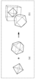
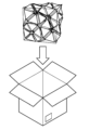
- FIG. 1 is a diagram showing an example of a three-dimensional structure generated from a plurality of polyhedra.
- FIG. 2 is a diagram showing another example of a three-dimensional structure generated from a plurality of polyhedra.
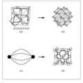
- FIG. 3 is a diagram showing still another example of a three-dimensional structure generated from a plurality of polyhedra.
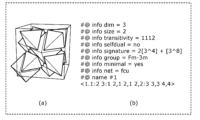
- FIG. 4 is a diagram showing an example of a crystal structure generated from a three-dimensional structure.
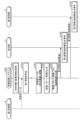
- FIG. 5 is a block diagram showing the overall configuration including the information processing system according to the first embodiment.
- FIG. 6 is a diagram illustrating an example of polyhedral data stored in the first storage unit.
- FIG. 7 is a diagram illustrating an example of second information stored in the second storage unit.
- FIG. 1 is a diagram showing an example of a three-dimensional structure generated from a plurality of polyhedra.
- FIG. 2 is a diagram showing another example of a three-dimensional structure generated from a plurality of polyhedra.
- FIG. 3
- FIG. 8 is a diagram showing an image displayed on the display unit in the first usage example of the first embodiment.
- FIG. 9 is a diagram showing an image displayed on the display unit in the first usage example of the first embodiment.
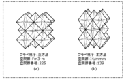
- FIG. 10 is a diagram showing a list of Bravais lattices.
- FIG. 11 is a diagram showing an image displayed on the display unit in the second usage example of the first embodiment.
- FIG. 12 is a diagram showing an example of the symmetry of a three-dimensional structure.
- FIG. 13 is a diagram showing an image displayed on the display unit in the third usage example of the first embodiment.
- FIG. 14 is a diagram showing an image displayed on the display unit in the fourth usage example of the first embodiment.
- FIG. 15 is a diagram showing an image displayed on the display unit in the fifth usage example of the first embodiment.
- FIG. 16 is a diagram showing an example of skewness of a polyhedron.
- FIG. 17 is a diagram showing an example of a three-dimensional structure with distortion.
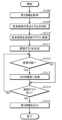
- FIG. 18 is a flowchart illustrating an example of the operation of the information processing system according to the first embodiment.
- FIG. 19 is a flowchart showing an example of the process of generating a polyhedron code from a polyhedron.
- FIG. 20 is a diagram showing an example of the process of generating a polyhedral code from a regular tetrahedron.
- FIG. 21 is a diagram showing an example of the process of generating a polyhedron code from a regular octahedron.
- FIG. 22 is a diagram showing an example of the process of generating a polyhedral code from a cuboctahedron.
- FIG. 23 is a flowchart showing an example of the process of generating a multivesicular code from a polyhedral code.
- FIG. 24 is a flowchart showing an example of the process of generating a three-dimensional structure from a multivesicular body code.
- FIG. 25 is a diagram showing a specific example of a multivesicular body code.
- FIG. 26 is a diagram showing a specific example of the process of generating a three-dimensional structure from a multivesicular body code.
- FIG. 27 is a sequence diagram illustrating an operation example of the information processing system, the display unit, the first storage unit, and the second storage unit according to the first embodiment.
- FIG. 28 is a flowchart showing another example of the operation of the information processing system according to the first embodiment.
- FIG. 29 is a diagram showing a specific example of the process of converting a polyhedron into a polyhedron graph.
- FIG. 30 is a diagram showing a specific example of converting a periodic graph into a three-dimensional structure.
- FIG. 31 is a diagram showing an image displayed on the display unit in the first usage example of the second embodiment.
- FIG. 32 is a diagram showing an image displayed on the display unit in the first usage example of the second embodiment.
- FIG. 33 is a diagram showing an image displayed on the display unit in the first usage example of the second embodiment.
- FIG. 34 is a sequence diagram showing a first operation example of the information processing system, the display section, the first storage section, and the second storage section according to the second embodiment.
- FIG. 35 is a diagram showing an image displayed on the display unit in the second usage example of the second embodiment.
- FIG. 36 is a diagram showing an image displayed on the display unit in the second usage example of the second embodiment.
- FIG. 37 is a sequence diagram showing a second operation example of the information processing system, the display section, the first storage section, and the second storage section according to the second embodiment.
- FIG. 38 is a block diagram showing the overall configuration including the information processing system according to the third embodiment.
- FIG. 34 is a sequence diagram showing a first operation example of the information processing system, the display section, the first storage section, and the second storage section according to the second embodiment.
- FIG. 35 is a diagram showing an image displayed on the display unit in the second usage example of the
- FIG. 39 is a diagram showing an image displayed on the display unit in the usage example of the third embodiment.
- FIG. 40 is a diagram showing an example of a three-dimensional structure related to a building.
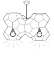
- FIG. 41 is a diagram showing an example of a three-dimensional structure regarding an ornament.
- FIG. 42 is a diagram showing an example of a three-dimensional structure related to an interior.
- FIG. 43 is a diagram showing an example of a three-dimensional structure regarding a toy.
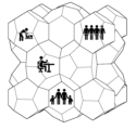
- FIG. 44 is a diagram showing an example of a three-dimensional structure related to urban design.
- FIG. 45 is a diagram showing an example of a three-dimensional structure related to storage.
- FIG. 46 is a diagram showing an example of a three-dimensional structure related to food.
- FIG. 40 is a diagram showing an example of a three-dimensional structure related to a building.
- FIG. 41 is a diagram showing an example of a three-dimensional structure regarding an ornament.
- FIG. 42 is a diagram showing an example of a
- FIG. 47 is a diagram showing an example of a three-dimensional structure regarding materials.
- FIG. 48 is a diagram showing sides a, b, and c of surface 1 of a regular tetrahedron.
- FIG. 49 is a diagram showing surface 1 of a regular tetrahedron.
- FIG. 50 is a diagram showing sides a, b, and c of face 1 of a regular octahedron.
- FIG. 51 is a diagram showing surface 2 of a regular octahedron.
- FIG. 52 is a diagram showing face 5 of a regular octahedron.
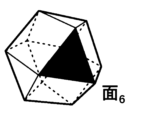
- FIG. 53 is a diagram showing face 6 of a regular octahedron.
- FIG. 48 is a diagram showing sides a, b, and c of surface 1 of a regular tetrahedron.
- FIG. 49 is a diagram showing surface 1 of a regular tetrahedron.
- FIG. 50 is a diagram showing sides a
- FIG. 54 is a diagram showing sides a, b, and c of face 1 of a cuboctahedron.
- FIG. 55 is a diagram showing surface 2 of a cuboctahedron.
- FIG. 56 is a diagram showing face 6 of the cuboctahedron.
- FIG. 57 is a diagram showing face 7 of the cuboctahedron.
- a space-dimensional structure is a structure in which a plurality of solids such as polyhedra fill a three-dimensional space without gaps.
- the three-dimensional structure here refers to a structure in which a plurality of polyhedra are arranged without gaps in a three-dimensional space.
- the three-dimensional structure refers to a structure in which a plurality of polyhedra including two or more types of polyhedra having mutually different shapes are arranged without gaps in a three-dimensional space.
- the structure of a material is the microstructure of a material such as a crystalline material or an amorphous material.
- a material such as a crystalline material or an amorphous material.
- an atom exists in coordination with and surrounded by a plurality of adjacent atoms.
- the structure of an inorganic material is made up of polyhedra (coordination polyhedra) formed by connecting the centers of a plurality of adjacent atoms, filling a three-dimensional space without gaps.
- the structure of the inorganic material can be regarded as a three-dimensional structure.
- FIG. 1 is a diagram showing an example of a three-dimensional structure generated from a plurality of polyhedra.
- the three-dimensional structure generated from two regular tetrahedrons and one regular octahedron shown in FIG. 1(a) has a face-centered cubic lattice shown in FIG.
- FIG. 2 is a diagram showing another example of a three-dimensional structure generated from a plurality of polyhedra.
- FIG. 3 is a diagram showing still another example of a three-dimensional structure generated from a plurality of polyhedra.
- a three-dimensional structure generated from one regular octahedron and one cuboctahedron shown in FIG. 3(a) includes a perovskite structure shown in FIG. 3(b).
- one cuboctahedron is shown in FIG. 3(b)
- a plurality of cuboctahedrons are arranged without gaps around the regular octahedron at the center.
- three-dimensional structures have the potential to be applied not only to material structures but also to a variety of other uses, such as the design of buildings.
- Patent Document 1 discloses a method of generating a three-dimensional spatial figure that allows gaps. However, Patent Document 1 does not disclose a method for generating a three-dimensional structure in which a plurality of polyhedra are arranged without gaps.
- Patent Document 2 discloses a method of generating housing structure data by combining three-dimensional blocks and performing a simulation of the housing structure using the housing structure data.
- Patent Document 2 only discloses housing structure data by combining three-dimensional blocks with the same shape, but does not disclose a method for generating a three-dimensional structure using two or more types of polyhedra with different shapes. Not yet.
- Non-Patent Document 1 discloses a polyhedral code that describes a polyhedron in a number sequence, and a multivesicular body code that describes a multivesicular body in a number sequence. However, Non-Patent Document 1 does not disclose a technique for using these to generate a three-dimensional structure in which a plurality of polyhedra are arranged without gaps.
- an information processing method is an information processing method executed by a computer, in which first information regarding a plurality of polyhedra including two or more types of polyhedra having different shapes from each other is provided. , a step of generating second information regarding a three-dimensional structure in which the plurality of polyhedra are arranged based on the first information, and a step of outputting the generated second information,
- the three-dimensional structure is a structure in which the plurality of polyhedra are arranged without gaps.
- the second information is at least one of information indicating the three-dimensional structure, information indicating a numerical sequence including numbers or letters indicating the three-dimensional structure, and information indicating a periodic graph indicating the three-dimensional structure. It may include one.
- shape information indicating the shape of each of the plurality of polyhedra is acquired as the first information
- shape information indicated by the shape information is The second information regarding the three-dimensional structure in which the plurality of polyhedra are arranged without gaps may be generated.
- step of acquiring the first information number information indicating the number of each shape of the plurality of polyhedra is further acquired as the first information, and in the step of generating the second information, the shape information is The second information regarding the three-dimensional structure may be generated in which the plurality of polyhedra having the indicated shapes are arranged without gaps in the number corresponding to each shape indicated by the number information.
- composition ratio information indicating the composition ratio of each shape of the plurality of polyhedra is further acquired as the first information
- second information regarding the three-dimensional structure may be generated in which the plurality of polyhedra having shapes indicated by the information are arranged without gaps in a composition ratio for each shape indicated by the composition ratio information.
- Second information regarding the three-dimensional structure may be generated by distorting at least a portion of the plurality of polyhedra such that the skewness does not exceed the skewness indicated by the skewness information.
- the skewness may include the position of the center of gravity of the polyhedron, the position of at least one vertex of the polyhedron, the length of at least one side of the polyhedron, and the length of at least one side of the polyhedron, based on the shape of the polyhedron indicated by the shape information.
- the determination may be based on at least one of an angle formed by at least two sides and an area of at least one face of the polyhedron.
- the method further includes the step of acquiring third information regarding the use of the three-dimensional structure, and in the step of generating the second information, the third information is added to the three-dimensional structure generated based on the first information.
- the second information regarding the three-dimensional structure may be generated with information based on the intended use.
- the step of generating the second information includes converting the acquired first information into a plurality of first number sequences representing each of the plurality of polyhedra, and generating the second information using the converted first number sequences. converting the second number sequence representing the multivesicular body into the three-dimensional structure.
- the step of generating the second information includes a step of converting the acquired first information into a plurality of polyhedral graphs representing each of the plurality of polyhedra, and a step of generating the second information using the converted plurality of polyhedron graphs.
- the method may further include converting a periodic graph into the three-dimensional structure.
- an information processing system includes a display unit that displays a first image that receives an input of first information regarding a plurality of polyhedra including two or more types of polyhedra having mutually different shapes; a display control unit that causes the display unit to display a second image representing second information about the three-dimensional structure in which the plurality of polyhedra are arranged, which is generated based on the first information, and the three-dimensional structure is , is a structure in which the plurality of polyhedra are arranged without gaps.
- the display unit further displays a third image that receives input of third information regarding the use of the three-dimensional structure, and the three-dimensional structure is generated based on the input first information, and
- the structure may include information based on the purpose indicated by the input third information.
- the program according to one aspect of the present disclosure includes the steps of: acquiring first information regarding a plurality of polyhedra including two or more types of polyhedra having mutually different shapes; and arranging the plurality of polyhedra based on the first information. a step of generating second information regarding the generated three-dimensional structure; and a step of outputting the generated second information; and the three-dimensional structure is a structure in which the plurality of polyhedra are arranged without gaps It is.
- the present invention can also be implemented as a computer program that causes a computer to execute the characteristic processing included in the information processing method of the present disclosure. It goes without saying that such a computer program can be distributed via a computer-readable non-transitory recording medium such as a CD-ROM or a communication network such as the Internet.
- the information processing system may be configured such that all the components are included in one computer, or may be configured as a system in which multiple components are respectively distributed among multiple computers. It's okay.
- the three-dimensional structure is a structure that becomes a crystal structure when atoms are arranged. That is, in the first embodiment, the three-dimensional structure is used for materials such as inorganic materials.
- Inorganic genes include, for example, K.
- CRYSTAL-SELFIES which is an application of SELFIE proposed by Krenn et al., which can express a molecular structure using a string of alphabets, to a three-dimensional structure.
- an inorganic gene is, for example, a multivesicular code that can be converted into a three-dimensional structure.
- the multivesicular body code of type A zeolite (LTA) structure is represented by the numerical sequence "OHG 4 (HG) 4 H”.
- “O”, “H”, and “G” are called a polyhedron code, which is a sequence determined from the input polyhedron.
- “O” means a truncated octahedron, and is represented by the sequence "46 4 (46) 4 4".
- “H” means a cube, and is represented by the numerical sequence "46”.
- G means a truncated cuboctahedron, and is represented by the numerical sequence "6 (48) 3 (64) 6 (84) 3 6".
- this multivesicular body code By changing the arrangement of this multivesicular body code, another three-dimensional structure composed of the same plurality of polyhedra can be generated. Furthermore, by changing the polyhedron code, any polyhedron can be expressed. In this way, by using inorganic genes typified by multivesicular body codes, it becomes possible to comprehensively generate three-dimensional structures from information on multiple polyhedra.
- FIG. 4 is a diagram showing an example of a crystal structure generated from a three-dimensional structure.
- Figure 4(a) represented as "3 4 (3 6 ) 4 (3 4 ) 6 3 4 " in the multivesicular body code
- Figure 4(b) is It is possible to produce crystalline structures.
- a molecular structure can be expressed as a graph. That is, the molecular structure can be expressed as a graph structure in which the "atoms" constituting a compound are “nodes” and the “bonds between atoms" are “edges” connecting the nodes.
- the molecular structure is expressed as a graph and a molecular structure is generated is disclosed in JP-A-2021-081769.
- a periodic graph is also called a crystal net, and is a three-dimensional periodic graph.
- "three-dimensionally periodic” means that three linearly independent translations exist.
- a crystal structure can be converted into a periodic graph by defining the bonds between atoms in the crystal structure.
- a periodic graph can be uniquely converted into a crystal structure.
- a periodic graph with two independent nodes and four edges connecting them as shown in Figure 4(c)
- Figure 4(d) can be interconverted with the diamond-shaped structure shown in Figure 4(d).
- a periodic graph is a graph that has a structure in which a plurality of polyhedra are arranged without gaps, and that can be converted into a three-dimensional structure that becomes a crystal structure when atoms are arranged.
- FIG. 5 is a block diagram showing the overall configuration including the information processing system 100 according to the first embodiment.
- the information processing system 100 is configured as a computer such as a personal computer or a server, for example. That is, the information processing system 100 may be realized by cloud computing, for example.
- Embodiment 1 will be described assuming that information processing system 100 is a stationary computer.
- the information processing system 100 includes an acquisition unit 11, a generation unit 12, and an output unit 13. Further, the information processing system 100 is connected to an input section 2, a display control section 30, a display section 3, a first storage section 4, and a second storage section 5.
- the input unit 2, the display control unit 30, and the display unit 3 are configured by an information terminal used by a user, such as a smartphone, a tablet terminal, or a personal computer.
- the input unit 2, display control unit 30, and display unit 3 may be an input unit, a display control unit, and a display unit included in an information terminal used by a user.
- the input unit 2, the display control unit 30, the first storage unit 4, and the second storage unit 5 may all be connected to the information processing system 100 via a LAN (Local Area Network) or the like, or may be connected to the information processing system 100 via a LAN (Local Area Network) or the like. It may be connected to the information processing system 100 via a network.
- LAN Local Area Network
- the input unit 2, the display control unit 30, the first storage unit 4, and the second storage unit 5 may all be connected to the information processing system 100 via a LAN (Local Area Network) or the like, or may be connected to the information processing system 100 via a LAN (Local Area Network) or the like. It may be connected to the information processing system 100 via a network.
- the input unit 2 is an input interface that accepts user input, and is composed of, for example, a keyboard, a touch sensor, a touch pad, a mouse, or the like.
- the input unit 2 receives an input operation by a user, and outputs a signal corresponding to the input operation to the information processing system 100.
- the display section 3 and the input section 2 are configured independently from each other, but they may be configured integrally like a touch panel.
- the information processing system 100 does not include the display unit 3 and the input unit 2, but may include these.
- the input unit 2 receives input of first information regarding a plurality of polyhedra.
- the first information may include, for example, the type of polyhedron, the number of polyhedra, the allowed skewness, or the allowed symmetry. Details of the first information and input of the first information by the input unit 2 will be described later.
- the display control unit 30 causes the display unit 3 to display images and the like based on information output from the output unit 13 of the information processing system 100.
- the display unit 3 displays images and the like under the control of the display control unit 30.
- the display unit 3 is, for example, a liquid crystal display, a plasma display, an organic EL (Electro-Luminescence) display, or the like, but is not limited thereto.
- the first storage unit 4 is a recording medium for storing a polyhedron database.
- the recording medium is, for example, a hard disk drive, RAM (Random Access Memory), ROM (Read Only Memory), or semiconductor memory. Note that such a recording medium may be volatile or nonvolatile.
- the polyhedron database includes data regarding the polyhedron, such as a diagram of the polyhedron, the number of vertices, the number of sides, the number of faces, or the shape of the face of the polyhedron.
- Examples of polyhedra recorded in the polyhedron database include regular polyhedra such as a regular tetrahedron, a regular hexahedron, a regular octahedron, a regular dodecahedron, and a regular icosahedron.
- Examples of polyhedra include truncated tetrahedron, truncated hexahedron, truncated octahedron, truncated dodecahedron, truncated icosahedron, cuboctahedron, icosico-dodecahedron, and orthorhombic cube.
- the polyhedral data is used when the user inputs first information through the input unit 2.
- FIG. 6 is a diagram showing an example of polyhedron data stored in the first storage unit 4.
- 6(a) shows the structure of a polyhedron (here, a regular octahedron)
- FIG. 6(b) shows the structure of the polyhedron shown in FIG. 6(a) in a predetermined description format (here, a regular octahedron). , xyz file format).
- the first storage unit 4 stores polyhedral data such as an image showing the structure of a polyhedron as shown in FIG. 6(a), and data written in a predetermined description format as shown in FIG. 6(b). Saved as .
- the second storage unit 5 is a recording medium for storing second information regarding the three-dimensional structure generated by the generation unit 12.
- the recording medium is, for example, a hard disk drive, RAM (Random Access Memory), ROM (Read Only Memory), or semiconductor memory. Note that such a recording medium may be volatile or nonvolatile.
- FIG. 7 is a diagram showing an example of the second information stored in the second storage unit 5.
- FIG. 7(a) shows the three-dimensional structure (in this case, an FCC type structure) indicated by the second information
- FIG. 7(b) shows the three-dimensional structure shown in FIG. 7(a). It shows data written in a predetermined description format (here, D-Symbol format).
- the second storage unit 5 stores, for example, an image showing a three-dimensional structure as shown in FIG. 7(a), and data described in a predetermined description format as shown in FIG. 7(b). Saved as information.
- the second information includes, for example, three-dimensional data, graph data, space group, Wyckoff label, cell size, coordinates, maximum distortion of a polyhedron, and the like.
- the file format (extension) of the data saved in the second storage unit 5 is, for example, *. sldprt, *. sldasm, *. iam, *. ipt, *. model, *. CATPart, *. CATProduct, *. 3ds, or *. max etc.
- the file format (extension) please refer to the site indicated by the URL "https://www.data-henkan.com/extension-list”.
- the acquisition unit 11 acquires first information regarding a plurality of polyhedra including two or more types of polyhedra with mutually different shapes.
- the acquisition unit 11 is the main body that executes the step of acquiring the first information in the information processing method of the present disclosure. Specifically, the acquisition unit 11 acquires the first information input by the user through the input unit 2. As will be described later, the user performs an operation to input the first information while viewing the first image displayed on the display unit 3 and accepting input of the first information.
- the generation unit 12 generates second information regarding a three-dimensional structure in which a plurality of polyhedra are arranged, based on the first information acquired by the acquisition unit 11.
- the generation unit 12 is the main entity that executes the step of generating the second information in the information processing method of the present disclosure.
- the generation unit 12 performs a process of converting the acquired first information into a plurality of first number sequences each representing a plurality of polyhedra, and a multivesicular body generated using the converted plurality of first number sequences.
- a process of converting the second number sequence representing , into a three-dimensional structure is executed.
- the generation unit 12 converts each of the plurality of polyhedra into polyhedral codes (first number sequence), and converts the multivesicular code (second number sequence) generated using the plurality of polyhedron codes into a three-dimensional structure. Process and execute. Details of each of the above processes will be described later.
- the output unit 13 causes the display unit 3 to display the image etc. by outputting the image etc. to the display control unit 30. Furthermore, the output unit 13 outputs the second information generated by the generation unit 12.
- the output unit 13 is the main body that executes the step of outputting the second information in the information processing method of the present disclosure. Specifically, the output unit 13 outputs the second information by displaying the second image representing the second information generated by the generation unit 12 on the display unit 3. As will be described later, the user performs an operation to select second information to be stored in the second storage unit 5 while viewing the second image displayed on the display unit 3.
- Examples of usage of the information processing system 100 according to the first embodiment will be listed below.
- the information processing system 100 may apply any one of the first to fifth usage examples described below, or may apply a combination of multiple usage examples. Further, in the following description of the second to fifth usage examples, descriptions of points common to the first usage example will be omitted.
- FIG. 8 and 9 are diagrams showing images displayed on the display unit 3 in the first usage example of the first embodiment.
- (a) of FIG. 8 represents an example of the first image displayed on the display unit 3.
- the first image is displayed on the display unit 3 by the output unit 13 by reading the polyhedron data stored in the first storage unit 4.
- the first image includes a shape selection area for selecting the shape of a polyhedron, a unit structure selection area for selecting a unit structure (in this case, a Bravais lattice), and a ⁇ generate three-dimensional structure'' function. '' and an execution icon.
- the shape selection area a plurality of polyhedra that can be selected by the user and a plurality of selection buttons respectively corresponding to the plurality of polyhedra are displayed.
- the shape name of each polyhedron may be displayed in the shape selection area.
- each polyhedron may be displayed as a moving image instead of a still image.
- the user selects a polyhedron to be included in the three-dimensional structure in the shape selection area.
- the acquisition unit 11 (in the step of acquiring the first information) acquires shape information indicating the shape of each of the plurality of polyhedra as the first information.
- the generation unit 12 when the user selects the execution icon, the generation unit 12 (in the step of generating second information) generates second information regarding a three-dimensional structure in which a plurality of polyhedra having the shape indicated by the shape information are arranged without gaps. do.
- the user has selected a regular tetrahedron and a regular octahedron. Therefore, in this case, the generation unit 12 generates second information regarding a three-dimensional structure in which regular tetrahedrons and regular octahedrons are arranged without gaps.
- the unit structure selection area displays the types of unit structures (in this case, Bravais lattice) that can be selected by the user.
- the user can select either "cubic” or “tetragonal”; however, for example, in FIG. It may also be possible to select one from the list of Bravais lattices shown in .
- FIG. 10 is a diagram showing a list of Bravais lattices.
- the user selects a unit structure (here, a Bravais lattice) in the unit structure selection area.
- the acquisition unit 11 acquires, as the first information, unit structure information indicating the shape of the unit structure in which a plurality of polyhedra are arranged without gaps.
- the unit structure information is information indicating a Bravais lattice in a crystal structure.
- the generation unit 12 in the step of generating the second information
- the generation unit 12 generates a three-dimensional structure in which at least one unit structure (in this case, a Bravais lattice) indicated by the unit structure information is arranged. Generate second information regarding.
- FIG. 8(b) shows an example of the second image displayed on the display unit 3.
- the second image is displayed on the display unit 3 after the user selects the execution icon in the first image and the generation unit 12 generates second information regarding the three-dimensional structure.
- the second image includes a table showing a list of three-dimensional structures generated by the generation unit 12 and an execution icon that says "Export selected three-dimensional structure.”
- a column for selecting the 3D structure to be exported a column for displaying the identification number (ID) for each 3D structure, and a number for each shape of multiple polyhedra included in the 3D structure.
- a column indicating the composition ratio (here, the composition ratio) and a column indicating the symmetry of the three-dimensional structure (here, the space group) are displayed.
- the user selects the three-dimensional structure that he or she wants to save and selects the execution icon.
- the display unit 3 displays an image including an area showing the selected three-dimensional structure and an execution icon "Save image”.
- the user checks the selected three-dimensional structure and selects the execution icon if there is no problem.
- the display unit 3 displays an image including a selection area for selecting the storage format of the three-dimensional structure and an execution icon "save".
- the user can select either ".slbprt" or ".slbasm", but even if the user can select other storage formats, good.
- second information regarding the three-dimensional structure selected by the user is stored in the second storage unit 5.
- FIG. 11 is a diagram showing an image displayed on the display unit 3 in the second usage example of the first embodiment.
- FIG. 11 shows an example of the first image displayed on the display section 3.
- the first image includes a symmetry specification area for specifying the symmetry (here, space group) of the three-dimensional structure instead of the unit structure selection area. Contains.
- FIG. 12 is a diagram showing an example of the symmetry of a three-dimensional structure.
- the three-dimensional structure shown in FIG. 12(a) has symmetry shown by the space group "Fm3-m” with the space group number "225".
- the three-dimensional structure shown in FIG. 12(b) has symmetry shown by the space group "l4/mmm” of the space group number "139".
- space groups please refer to the site indicated by the URL "https://en.wikipedia.org/wiki/List_of_space_groups”.
- the user specifies the symmetry of the three-dimensional structure by inputting the number of the desired space group into the text box in the symmetry specification area.
- the range of desired space group numbers may be input in the text box.
- the acquisition unit 11 acquires symmetry information indicating the symmetry of the three-dimensional structure as the first information.
- the symmetry information is information indicating a space group in a crystal structure.
- the generation unit 12 in the step of generating second information
- the generation unit 12 generates second information regarding the three-dimensional structure having the symmetry (here, space group) indicated by the symmetry information. generate.
- a plurality of space groups that can be selected by the user may be listed in the symmetry specification area of the first image instead of a text box. In this case, the user only has to select one of the plurality of space groups.
- FIG. 13 is a diagram showing an image displayed on the display unit 3 in the third usage example of the first embodiment.
- FIG. 13 shows an example of the first image displayed on the display unit 3.
- the first image is a number for specifying the number of multiple polyhedra included in a three-dimensional structure for each shape of the polyhedron. Contains the specified area.
- the name of the shape of the polyhedron selected in the shape selection area and a text box for specifying the number of polyhedra to be included in the three-dimensional structure are displayed.
- the user has selected a regular tetrahedron and a regular octahedron in the shape selection area. Therefore, a text box for specifying the number of regular tetrahedra and a text box for specifying the number of regular octahedrons are displayed in the number specifying area.
- the user specifies the number of polyhedra to be included in the three-dimensional structure by inputting the desired number into the text box in the number specification area.
- the acquisition unit 11 in the step of acquiring the first information further acquires, as the first information, number information indicating the number of each shape of the plurality of polyhedra.
- the generation unit 12 in the step of generating the second information arranges a plurality of polyhedra of the shape indicated by the shape information without gaps for each shape indicated by the number information. second information regarding the three-dimensional structure is generated.
- FIG. 14 is a diagram showing an image displayed on the display unit 3 in the fourth usage example of the first embodiment.
- FIG. 14 shows an example of the first image displayed on the display section 3.
- the first image includes a composition ratio specification area for specifying the composition ratio for each polyhedral shape included in the three-dimensional structure, instead of a unit structure selection area. Contains.
- the composition ratio specification area displays the name of the shape of the polyhedron selected in the shape selection area and a text box for specifying the composition ratio of the polyhedron to be included in the three-dimensional structure.
- the user has selected a regular tetrahedron and a regular octahedron in the shape selection area. Therefore, in the composition ratio designation area, a text box for specifying the composition ratio of the regular tetrahedron and a text box for specifying the composition ratio of the regular octahedron are displayed.
- the user specifies the composition ratio for each shape of the plurality of polyhedra to be included in the three-dimensional structure by inputting the desired composition ratio into the text box in the composition ratio specification area.
- the acquisition unit 11 in the step of acquiring the first information further acquires composition ratio information indicating the composition ratio of each shape of the plurality of polyhedra as the first information.
- the generation unit 12 in the step of generating the second information generates a plurality of polyhedra of the shape indicated by the shape information without any gaps at the composition ratio of each shape indicated by the composition ratio information. Second information regarding the placed three-dimensional structure is generated.
- FIG. 15 is a diagram showing an image displayed on the display unit 3 in the fifth usage example of the first embodiment.
- (a) of FIG. 15 represents an example of the first image displayed on the display unit 3.
- the first image includes a skewness designation area for designating the allowable skewness of the shapes of the plurality of polyhedrons.
- the degree of distortion indicates the degree to which the shape of the polyhedron is distorted based on the shape of the polyhedron indicated by the shape information, that is, the shape of the polyhedron displayed in the shape selection area.
- the skewness is based on the shape of the polyhedron indicated by the shape information, the position of the center of gravity of the polyhedron, the position of at least one vertex of the polyhedron, the length of at least one side of the polyhedron, and the position of at least two sides of the polyhedron. It is determined based on at least one of the angle and the area of at least one face of the polyhedron.
- the generation unit 12 attempts to generate a three-dimensional structure within the range of distortion allowed by the user.
- the skewness is expressed by the following equation (1) using, for example, Baur's method.
- “D” is the skewness
- "l i” is the distance from the center of the polyhedron to the i-th vertex
- " lav " is the average distance from the center of the polyhedron to the vertex.
- Equation (2) the skewness is expressed by the following equation (2) using, for example, Robinson's method (quadratic elongation).
- ⁇ is the skewness
- l i is the distance from the center of the polyhedron to the i-th vertex
- l 0 is the distance from the center to the vertex of a regular polyhedron with the same volume.
- FIG. 16 is a diagram showing an example of the skewness of a polyhedron.
- FIG. 16A shows the shape of a polyhedron (here, a regular tetrahedron) having no distortion when the skewness "D" is "0.0".
- FIG. 16(b) shows a case where the skewness "D" is "0.00869", that is, a polyhedron having distortion (here, the shape of a regular tetrahedron).
- FIG. 17 is a diagram showing an example of a three-dimensional structure with distortion.
- FIG. 17 shows a three-dimensional structure (here, a bcc-type structure) in which a plurality of distorted polyhedra (here, polyhedra obtained by distorting a regular tetrahedron) are arranged without gaps.
- a text box for specifying the allowable skewness of the shapes of multiple polyhedra is displayed.
- the user specifies the allowable skewness of the shapes of the plurality of polyhedra by inputting the desired skewness into the text box in the skewness specification area.
- a desired range of skewness may be input in the text box.
- the acquisition unit 11 in the step of acquiring the first information further acquires skewness information indicating the allowable skewness of the shapes of the plurality of polyhedra as the first information.
- the generation unit 12 distorts at least some of the plurality of polyhedra so as not to exceed the skewness indicated by the skewness information. Generate second information regarding the dimensional structure.
- FIG. 15(b) shows an example of the second image displayed on the display unit 3.
- the second image displays total distortion, which is the sum of distortions of the three-dimensional structures, in a table showing a list of three-dimensional structures generated by the generation unit 12. It further includes a column.
- FIG. 18 is a flowchart illustrating an example of the operation of the information processing system 100 according to the first embodiment.
- Step S101 The acquisition unit 11 acquires first information.
- the first information is input (selected) by the user using the input unit 2 while reading the polyhedron data stored in the first storage unit 4 and viewing the first image displayed on the display unit 3. ), the data is acquired by the acquisition unit 11.
- the first information may be acquired by the acquisition unit 11 by the user inputting original data using the input unit 2 without referring to the first image.
- Step S102 The generation unit 12 executes a process of converting the first information acquired by the acquisition unit 11 into a plurality of first number sequences each representing a plurality of polyhedra.
- the generation unit 12 converts each polyhedron included in the first information into a polyhedron code.
- Step S103 The generation unit 12 executes a process of generating a second number sequence representing a multivesicular body using the plurality of converted first number sequences.
- the generation unit 12 generates a plurality of polyhedral codes based on the plurality of polyhedral codes obtained by the conversion.
- Step S104 The generation unit 12 determines whether the generated multivesicular body code can be converted into a three-dimensional structure.
- the generation unit 12 generates a multivesicular body code based on, for example, whether the faces of two polyhedra that touch each other are the same, or whether a plurality of polyhedra are arranged without gaps (in other words, whether the filling rate is 100% or not). It is possible to determine whether conversion to a three-dimensional structure is possible. If it is determined that conversion is possible (step S104: Yes), the generation unit 12 next executes step S105. If it is determined that conversion is not possible (step S104: No), the generation unit 12 next executes step S106.
- Step S105 The generation unit 12 executes a process of converting the multivesicular body code into a three-dimensional structure.
- K the above-mentioned K.
- the generation unit 12 then executes step S106.
- Step S106 The generation unit 12 determines whether there is a multivesicular body code whose convertibility has not yet been determined. If there is a multivesicular body code that has not been determined yet (S106: Yes), the generation unit 12 returns to step S104. When all the multivesicular body codes are determined (S106: No), the processing of the generation unit 12 is completed. The information processing system 100 (information processing method) then executes step S107.
- Step S107 The output unit 13 executes a process of outputting the second information generated by the generation unit 12.
- the output unit 13 outputs the second information by displaying the second image representing the second information generated by the generation unit 12 on the display unit 3.
- the display section 3 may include a display control section 30.
- the display section 3 including the display control section 30 may be referred to as a display section 3A.
- the output unit 13 may output the second information generated by the generation unit 12 to the display unit 3A. Thereby, the display section 3A may display the second information. That is, the output unit 13 may display the second information on the display unit 3A.
- the generation unit 12 cannot convert all the multivesicular body codes into a three-dimensional structure, the second information is not generated. If the generation unit 12 cannot convert all the multivesicular body codes into a three-dimensional structure, the second information is not displayed on the display unit 3.
- FIG. 19 is a flowchart showing an example of the process of generating a polyhedron code from a polyhedron.
- Step S201 The generation unit 12 assigns the number "1" to any face of the polyhedron.
- Step S202 The generation unit 12 assigns "1" to the variable "i”.
- Step S203 The generation unit 12 assigns the number "i+1" to the surface adjacent to the "i"-th surface.
- Step S204 The generation unit 12 assigns numbers to the variable "j" number of faces adjacent to the "i” and following faces in a clockwise direction from the "i+1" face to the "i+j" face. The number of surfaces adjacent to the surface "i” or lower is assigned to the variable "j".
- Step S205 The generation unit 12 determines whether numbers have been assigned to all faces of the polyhedron. If all faces of the polyhedron have been numbered (step S205: Yes), the generation unit 12 next executes step S209. If all faces of the polyhedron have not yet been numbered (step S205: No), the generation unit 12 next executes step S206.
- Step S206 The generation unit 12 assigns the number "i+j+1" to an unnumbered surface adjacent to the "i+1" numbered surface.
- Step S207 The generation unit 12 determines whether numbers have been assigned to all faces of the polyhedron. If all faces of the polyhedron have been numbered (step S207: Yes), the generation unit 12 next executes step S209. If all faces of the polyhedron have not yet been numbered (step S207: No), the generation unit 12 next executes step S208.
- Step S208 The generation unit 12 assigns "i+j" to the variable "i”. The generation unit 12 then returns to step S204.
- Step S209 The generation unit 12 converts the number of sides of each face into a numerical sequence by arranging the number of sides of each face in the order of the numbers given to all the faces of the polyhedron.
- Step S210 The generation unit 12 determines whether there are any other sequence patterns. If there are other sequence patterns (step S210: Yes), the generation unit 12 returns to step S201. In this case, in step S201, the generation unit 12 assigns the number "1" to an arbitrary surface different from the surface previously assigned the number "1". If there are no other sequence patterns (step S210: No), the generation unit 12 next executes step S211.
- Step S211 The generation unit 12 selects the smallest number sequence from one or more number sequences.
- the selected number sequence becomes the polyhedral code.
- FIG. 20 is a diagram showing an example of the process of generating a polyhedral code from a regular tetrahedron.
- the generation unit 12 assigns a number "1" to an arbitrary surface.
- the generation unit 12 sequentially assigns numbers "2", “3", and "4" to the faces adjacent to the face "1" clockwise (left-handed).
- the surface numbered “1” is surface 1
- the surface numbered “2” is surface 2
- the surface numbered “3” is surface 3
- the surface numbered "4" is surface 2.
- the surface be surface 4 .
- Surface 1 is the front right surface of each regular tetrahedron shown in FIG. The three sides of surface 1 are named, clockwise, side a, side b, and side c.
- FIG. 48 is a diagram showing sides a, b, and c of surface 1 of a regular tetrahedron.
- FIG. 49 is a diagram showing surface 1 of a regular tetrahedron. In FIG. 49, surface 1 is filled in black.
- Surface 2 shares side a with surface 1
- surface 3 shares side b with surface 1
- surface 4 shares side c with surface 1 .
- the generation unit 12 converts the number of sides of the faces into a numerical sequence in numerical order using terms as terms.
- FIG. 21 is a diagram showing an example of the process of generating a polyhedron code from a regular octahedron.
- the generation unit 12 assigns a number "1" to an arbitrary surface. Then, the generation unit 12 sequentially assigns numbers “2", “3", and “4" to the faces adjacent to the face "1" clockwise (left-handed).
- the generation unit 12 assigns a number "5" to a surface that is adjacent to the surface "2" and has not been assigned a number yet.
- the generation unit 12 sequentially assigns numbers "6" and "7” clockwise (left-handed) from the "5" face to the faces adjacent to the faces assigned numbers "4" and below. do.
- the generation unit 12 assigns the number "8" to a surface adjacent to the surface "5" and to which no number has been assigned yet.
- FIG. 21 the surface numbered “1" is surface 1
- the surface numbered “8” is surface 8
- Surface 1 is the far right surface in each regular octahedron shown in FIG.
- the three sides of surface 1 are named a, b, and c in clockwise order.
- FIG. 50 is a diagram showing sides a, b, and c of face 1 of a regular octahedron.
- Surface 2 shares side a with surface 1
- surface 3 shares side b with surface 1
- surface 4 shares side c with surface 1 .
- FIG. 51 is a diagram showing surface 2 of a regular octahedron. In FIG. 51, surface 2 is filled in black.
- FIG. 51 is a diagram showing surface 2 of a regular octahedron. In FIG. 51, surface 2 is filled in black.
- FIG. 52 is a diagram showing face 5 of a regular octahedron. In FIG. 52, surface 5 is filled in black.
- FIG. 53 is a diagram showing face 6 of a regular octahedron. In FIG. 53, surface 6 is filled in black.
- the generation unit 12 converts the number of sides of the faces into a numerical sequence in numerical order using terms as terms.
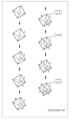
- FIG. 22 is a diagram showing an example of the process of generating a polyhedron code from a cuboctahedron.
- the generation unit 12 assigns a number "1" to an arbitrary surface. Then, the generation unit 12 sequentially assigns numbers “2", “3", and “4" to the faces adjacent to the face "1" clockwise (left-handed).
- the generation unit 12 assigns a number "5" to a surface that is adjacent to the surface "2" and has not been assigned a number yet. Then, the generation unit 12 sequentially generates "6", "7", and “8” in clockwise (left-handed) order from the "5" face on the faces adjacent to the faces assigned numbers "4" and below. , “9", and "10".
- the generation unit 12 assigns a number "11” to a surface adjacent to the surface "5" and to which no number has been assigned yet. Then, the generation unit 12 sequentially assigns numbers "12" and “13” clockwise (left-handed) from the "11" face to the faces adjacent to the faces assigned numbers "10" and below. do. Furthermore, the generation unit 12 assigns a number "14" to a surface that is adjacent to the surface "11” and has not been assigned a number yet.
- FIG. 22 is a diagram showing sides a, b, and c of face 1 of a cuboctahedron.
- Surface 2 shares side a with surface 1
- surface 3 shares side b with surface 1
- surface 4 shares side c with surface 1 .
- FIG. 55 is a diagram showing surface 2 of a cuboctahedron. In FIG. 55, surface 2 is filled in black.
- FIG. 56 is a diagram showing face 6 of the cuboctahedron. In FIG. 56, surface 6 is filled in black.
- FIG. 57 is a diagram showing face 7 of the cuboctahedron. In FIG. 57, surface 7 is filled in black.
- the generation unit 12 converts the number of sides of the faces into a numerical sequence in numerical order using terms as terms.
- the term corresponding to the surface is "3".
- sequence A is less than sequence B.
- sequence B is less than sequence B.
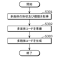
- FIG. 23 is a flowchart showing an example of the process of generating a multivesicular code from a polyhedral code.
- the acquisition unit 11 will be described as acquiring the shapes of each of the plurality of polyhedra and the number of each shape as the first information.
- Step S301 The generation unit 12 acquires the shape of each of the plurality of polyhedra and the number of each shape from among the first information acquired by the acquisition unit 11.
- Step S302 The generation unit 12 prepares a plurality of polyhedral codes by converting each of the plurality of polyhedrons into a polyhedral code.
- Step S303 The generation unit 12 generates a plurality of polyhedral codes based on the plurality of polyhedral codes.
- the generation unit 12 generates a plurality of polyhedral codes by rearranging the sequence "OOOOOTTTTTT" of the plurality of polyhedral codes.
- a plurality of polyhedral codes are generated based on a plurality of polyhedral codes, that is, eight T's and four O's.
- Each of the plurality of multivesicular cords includes eight T's and four O's.
- "OOOOOTTTTTTTT” and “TOOOOTTTTTT” are different multivesicular body codes.
- FIG. 24 is a flowchart showing an example of the process of generating a three-dimensional structure from a multivesicular body code.
- Step S401 The generation unit 12 generates a polyhedron corresponding to each term of the polyhedral code, that is, the polyhedral code.
- Step S402 The generation unit 12 assigns numbers to each face of the polyhedron clockwise in the order of the terms of the multivesicular body code. For example, if the polyhedra corresponding to the first term of the multivesicular code are assigned numbers "1" to "4", the polyhedra corresponding to the second term of the multivesicular code are assigned numbers starting from "5". be done. That is, the generation unit 12 assigns numbers to each face of each polyhedron so that the numbers do not overlap in each polyhedron.
- Step S403 The generation unit 12 determines the polyhedron having the lowest number of uncombined faces as a partial polyhedron.
- Step S404 The generation unit 12 selects the faces of the remaining polyhedrons having the same shape as the face with the smallest number of the partial polyhedron. For example, if the smallest numbered face of a partial polyhedron has a triangular shape, the same triangular faces are selected from the remaining polyhedra.
- one surface may be selected, or multiple surfaces may be selected.
- Step S405 The generation unit 12 combines the lowest numbered surface of the selected surfaces with the uncombined lowest numbered surface of the partial multivesicular body.
- Step S406 The generation unit 12 determines whether there is a set of unconnected faces between the faces of the partial multivesicular body and the faces of the remaining selected polyhedra. If there is a set of uncombined surfaces (step S406: Yes), the generation unit 12 next executes step S407. If there is no set of uncombined surfaces (step S406: No), the generation unit 12 next executes step S408.
- Step S407 The generation unit 12 combines the uncombined faces of the partial polyhedron and the remaining selected polyhedra. The generation unit 12 then returns to step S406.
- Step S408 The generation unit 12 determines whether there are any remaining uncombined polyhedra. If there are remaining uncombined polyhedra (step S408: Yes), the generation unit 12 returns to step S403. If there are no uncombined remaining polyhedra (step S408: No), the generation unit 12 next executes step S409.
- Step S409 The generation unit 12 determines whether all polyhedra are filled 100%, in other words, whether all polyhedra are arranged without gaps. If all polyhedra have been filled 100% (step S409: Yes), the processing of the generation unit 12 is completed. In this case, the generation unit 12 has converted the multivesicular body code into a three-dimensional structure. If all polyhedra are not filled 100% (step S409: No), the generation unit 12 next executes step S410.
- Step S410 The generation unit 12 discards three-dimensional structures whose filling rate is not 100%, and completes the process. In this case, the generation unit 12 does not convert the multivesicular body code into a three-dimensional structure.
- FIG. 25 is a diagram showing a specific example of a multivesicular body code.
- FIG. 26 is a diagram showing a specific example of the process of generating a three-dimensional structure from a multivesicular body code. As shown in FIG. 25, a case will be described below in which the multivesicular body code "TOOOOTTTTTT" is converted into a three-dimensional structure.
- the generation unit 12 converts the polyhedral codes "T” and "O" in the multivesicular code into corresponding polyhedrons.
- the polyhedron code "T” is a regular tetrahedron
- the polyhedron code “O” is a regular octahedron.
- the generation unit 12 assigns numbers to each face of the polyhedron clockwise in the order of the plurality of terms included in the multivesicular body code.
- each face of the regular tetrahedron corresponding to the first term (leftmost term) of the multivesicular body code is given a number from ⁇ 1'' to ⁇ 4'', and each face of the regular octahedron corresponding to the second term is assigned a number from ⁇ 1'' to ⁇ 4''.
- the faces are numbered from "5" to "10".
- the generation unit 12 determines the regular tetrahedron corresponding to the first term of the multivesicular body code as a partial multivesicular body.
- the generation unit 12 selects the remaining polyhedral faces having the shape of the smallest numbered face of the regular tetrahedron that is the partial multivesicular body.
- the shape of the face "1" which is the lowest numbered face of the partial multivesicle, is triangular, and the shapes of the faces of all remaining polyhedra are triangular, so the faces of all remaining polyhedra are selected.
- the generation unit 12 combines the lowest numbered surface of the selected surfaces with the uncombined lowest numbered surface of the partial multivesicular body.
- the "1" face of the regular tetrahedron, which is a partial multivesicular body, and the "5" face of the regular octahedron, which corresponds to the second term of the multivesicular body code are combined.
- the generation unit 12 repeats the process of joining the uncombined faces.
- the generation unit 12 combines the face with the lowest unbound number "2" of the partial multivesicular body and the face with the lowest unbound number "13" among the remaining selected polyhedra. .
- the generation unit 12 combines the face "3" and the face "21", and the face "4" and the face "29".
- the generation unit 12 since there are remaining uncombined polyhedra, the generation unit 12 generates a polyhedron (here, a polyhedron corresponding to the second term of the multivesicular body code) having the lowest unconnected face number among the remaining polyhedra.
- a regular octahedron is determined as a new partial multivesicular body, and the same process as above is repeated.
- the generation unit 12 generates a three-dimensional structure with a filling rate of 100% by repeating the above process until there are no remaining unbonded polyhedra.
- the generation unit 12 combines the face with the lowest unbound number "6" of the new partial multivesicular body with the face with the lowest unbound number "37” among the remaining selected polyhedra. .
- the generation unit 12 combines the faces "7" and "41", the faces “8” and “45”, and the faces "9” and "49”. , join the faces "10” and "53”, join the faces "11” and "57”, and join the faces "12” and "59”.
- the multivesicular body code "TOOOTTTTTTTTTT the three-dimensional structure generated by the generation unit 12 is an fcc type structure.
- FIG. 27 is a sequence diagram showing an example of the operation of the information processing system 100, the display section 3, the first storage section 4, and the second storage section 5 according to the first embodiment.
- Step S501 The acquisition unit 11 of the information processing system 100 acquires first information.
- the first information is input (selected) by the user using the input unit 2 while reading the polyhedral data stored in the first storage unit 4 and viewing the first image displayed on the display unit 3.
- the information is acquired by the acquisition unit 11.
- Step S502 The generation unit 12 of the information processing system 100 executes a process of converting each polyhedron included in the first information acquired by the acquisition unit 11 into a polyhedron code.
- Step S503 The generation unit 12 of the information processing system 100 executes a process of generating a plurality of polyhedral codes based on the plurality of polyhedral codes obtained by the conversion.
- Step S504 The generation unit 12 of the information processing system 100 executes a process of determining whether the generated multivesicular body code can be converted into a three-dimensional structure.
- Step S505 The generation unit 12 of the information processing system 100 executes a process of converting the multivesicular body code determined to be convertible into a three-dimensional structure.
- Step S506 The display unit 3 displays a second image representing second information output from the output unit 13 of the information processing system 100.
- Step S507 When the user selects a three-dimensional structure to save while viewing the second image displayed on the display unit 3, the information processing system 100 provides second information regarding the selected three-dimensional structure to the second storage unit 5. Thereby, the second storage unit 5 stores second information regarding the three-dimensional structure selected by the user.
- a three-dimensional structure that is, a three-dimensional It becomes possible to comprehensively generate space-filling structures in a space. Therefore, in Embodiment 1, it is possible to search for unknown materials using the comprehensively generated three-dimensional structure, so that it is possible to improve the efficiency of the search for unknown materials.
- a polyhedron is converted into a polyhedral code
- a multivesicular body code is generated from the converted polyhedral code
- the generated other body code is converted into a three-dimensional structure.
- the information processing system 100 according to the first embodiment may convert a polyhedron into a polyhedral graph, generate a periodic graph from the converted polyhedron graph, and convert the generated periodic graph into a three-dimensional structure.
- the generation unit 12 (the step of generating second information) converts the acquired first information into a plurality of polyhedron graphs each representing a plurality of polyhedra, and generates the second information using the converted polyhedron graphs.
- a process of converting a periodic graph into a three-dimensional structure may also be executed.
- FIG. 28 is a flowchart showing another example of the operation of the information processing system 100 according to the first embodiment.
- Step S108 The acquisition unit 11 acquires first information.
- the first information is input (selected) by the user using the input unit 2 while reading the polyhedron data stored in the first storage unit 4 and viewing the first image displayed on the display unit 3. ), the data is acquired by the acquisition unit 11.
- the first information may be acquired by the acquisition unit 11 by the user inputting original data using the input unit 2 without referring to the first image.
- Step S109 The generation unit 12 determines the position of the vertex of each polyhedron (vertex site) and the position of the center of each polyhedron (center site) based on the acquired first information.
- Step S110 The generation unit 12 executes a process of converting the first information acquired by the acquisition unit 11 into a plurality of polyhedron graphs each representing a plurality of polyhedra.
- the generation unit 12 converts each polyhedron included in the first information into a polyhedron graph.
- Step S111 The generation unit 12 executes a process of generating a periodic graph using the converted polyhedral graph.
- the generation unit 12 generates a plurality of periodic graphs based on a combination of a plurality of polyhedral graphs obtained by the conversion.
- Step S112 The generation unit 12 determines whether the generated periodic graph can be converted into a three-dimensional structure. For example, the generation unit 12 determines whether or not the faces of two polyhedra that touch each other are the same, and whether or not the plurality of polyhedra are arranged without gaps (in other words, whether the filling rate is 100% or not). It is possible to determine whether conversion to a dimensional structure is possible. If it is determined that conversion is possible (step S112: Yes), the generation unit 12 next executes step S113. If it is determined that conversion is not possible (step S112: No), the generation unit 12 next executes step S114.
- Step S113 The generation unit 12 executes a process of converting a periodic graph into a three-dimensional structure.
- the conversion process for example, the method shown in the above-mentioned Kotani-Sunada theory (Kotani-Sunada, 2000, Trans. Amer. Mat) can be used.
- the generation unit 12 then executes step S114.
- Step S114 The generation unit 12 determines whether there is a periodic graph whose convertibility has not yet been determined. If there is a periodic graph that has not been determined yet (S114: Yes), the generation unit 12 returns to step S112. If the determination is made for all periodic graphs (S114: No), the processing of the generation unit 12 is completed. The information processing system 100 (information processing method) then executes step S115.
- Step S115 The output unit 13 executes a process of outputting the second information generated by the generation unit 12.
- the output unit 13 outputs the second information by displaying the second image representing the second information generated by the generation unit 12 on the display unit 3.
- the display section 3 may include a display control section 30.
- the display section 3 including the display control section 30 may be referred to as a display section 3A.
- the output unit 13 may output the second information generated by the generation unit 12 to the display unit 3A. Thereby, the display section 3A may display the second information. That is, the output unit 13 may display the second information on the display unit 3A.
- FIG. 29 is a diagram showing a specific example of the process of converting a polyhedron into a polyhedron graph.
- FIG. 30 is a diagram showing a specific example of converting a periodic graph into a three-dimensional structure.
- the generation unit 12 determines each vertex site of the polyhedron and the center site of the polyhedron. In the case of the regular tetrahedron shown in FIG. 29(a), the generation unit 12 determines four vertex sites and one center site as shown in FIG. 29(b). Furthermore, in the case of the regular octahedron shown in FIG. 29(d), the generation unit 12 determines six vertex sites and one vertex site, as shown in FIG. 29(e).
- the generation unit 12 generates a polyhedron graph by connecting each vertex site and the center site of the polyhedron.
- the generation unit 12 When the polyhedron is a regular tetrahedron, the generation unit 12 generates a polyhedron graph in which edges extend from the center node to each of the four vertex nodes, as shown in FIG. 29(c). Further, when the polyhedron is a regular octahedron, the generation unit 12 generates a polyhedron graph in which edges extend from the center node to each of the six vertex nodes, as shown in FIG. 29(f).
- the generation unit 12 generates a periodic graph by connecting each vertex node in the generated polyhedral graph.
- the periodic graph shown in FIG. 30(a) is a periodic graph generated from two polyhedral graphs corresponding to two regular tetrahedra and one polyhedral graph corresponding to one regular octahedron. This periodic graph is generated by combining the vertex nodes of each polyhedral graph into one.
- the generation unit 12 then converts the generated periodic graph into a three-dimensional structure.
- the three-dimensional structure (fcc type structure) shown in FIG. 30(b) is generated by converting the periodic graph shown in FIG. 30(a).
- the information processing system 200 according to the second embodiment is different from the information processing system 100 according to the first embodiment in that the acquisition unit 11 acquires material information regarding the composition of the material as the first information.
- the information processing system 200 according to the second embodiment includes an acquisition section 11, a generation section 12, and an output section 13, and has a configuration similar to the information processing system 100 according to the first embodiment. Since these are common, their explanation will be omitted.
- 31, 32, and 33 are diagrams showing images displayed on the display section 3 in the first usage example of the second embodiment.
- 31(a) and 31(b) each represent an example of the first image initially displayed on the display unit 3.
- the display unit 3 may display the first image shown in FIG. 31(a), or may display the first image shown in FIG. 31(b).
- the first image shown in FIG. 31(a) includes an element selection area for selecting an element and an execution icon "Next".
- a periodic table is displayed in the element selection area.
- the user selects an element (atom) contained in a desired material in the element selection area.
- the element becomes the element arranged at the center of the polyhedron.
- the acquisition unit 11 acquires material information regarding the composition of the material (here, atoms contained in the material) as the first information. It turns out.
- the first image shown in FIG. 31(b) includes a composition specification area for specifying the composition of the material and an execution icon labeled "Next."
- a text box is displayed for the user to specify the desired composition of the material.
- the user enters the chemical formula of the desired material into the text box.
- the acquisition unit 11 acquires material information regarding the composition of the material (here, the composition of the material itself) as the first information.
- expressions using subscripts are omitted.
- FIG. 32 shows an example of the first image displayed second on the display unit 3.
- the first image shown in FIG. 32 is displayed on the display unit 3 when the user selects the execution icon in the first image shown in FIG. 31(a) or the first image shown in FIG. 31(b). be done.
- an arrangement designation area for specifying the arrangement of elements (atoms) included in the material and an execution icon "Next" are displayed.
- a table showing the number of each element in the polyhedron and the position (vertex or center) of each element in the polyhedron is displayed.
- the acquisition unit 11 acquires, as the first information, arrangement information regarding the arrangement of elements (atoms) in the three-dimensional structure.
- the acquisition unit 11 acquires, as the first information, placement information regarding the placement of elements (atoms) in the three-dimensional structure.
- FIG. 33 shows an example of the first image displayed third on the display unit 3.
- the first image shown in FIG. 33 is displayed on the display unit 3 when the user selects the execution icon in the first image shown in FIG. 32.
- the first image shown in FIG. 33 includes a combination selection area for selecting a combination of polyhedra, a skewness designation area, and an execution icon "generate three-dimensional structure".
- the first image shown in FIG. 33 may include, for example, a unit structure selection area instead of the skewness specification area. That is, any one of the first to fifth usage examples of the first embodiment, or a combination thereof, may be applied to the first image shown in FIG. 33, except for the combination selection area.
- the combination selection area displays combinations of a plurality of polyhedra that can be selected by the user based on the arrangement information, and a plurality of selection buttons that respectively correspond to the combinations of the plurality of polyhedra.
- the name of the shape of each polyhedron may be displayed in the combination selection area.
- each polyhedron may be displayed as a moving image instead of a still image.
- the user selects a combination of polyhedra to be included in the three-dimensional structure in the combination selection area.
- the acquisition unit 11 acquires, as the first information, shape information indicating the shape of each of the plurality of polyhedra and composition ratio information indicating the composition ratio of each shape. I will do it.
- the generation unit 12 determines number information indicating the number of each shape of a plurality of polyhedra based on the composition ratio information.
- n may be a natural number of 2 or more and a predetermined value. The following process may be performed for each of the plural pieces of number information.
- the generation unit 12 (in the step of generating the second information) generates second information regarding a three-dimensional structure in which a number of polyhedra having the shape indicated by the shape information are arranged without gaps in a number corresponding to the polyhedra.
- the generation unit 12 generates second information regarding a three-dimensional structure in which a plurality of polyhedra having the shape indicated by the shape information are arranged without any gaps in the composition ratio of each shape indicated by the composition ratio information.
- the above shape information and composition ratio information are information based on arrangement information. Therefore, it can be said that the generation unit 12 (in the step of generating the second information) generates the second information regarding the three-dimensional structure based on the arrangement of elements (atoms) indicated by the arrangement information.
- the second image is displayed on the display unit 3, similar to the first usage example of the first embodiment. Then, by selecting the three-dimensional structure that the user wants to save and the storage format of the three-dimensional structure, second information regarding the three-dimensional structure selected by the user is saved in the second storage unit 5.
- FIG. 34 is a sequence diagram showing a first operation example of the entire information processing system 200 according to the second embodiment, including the display section 3, the first storage section 4, and the second storage section 5.
- Step S601 The acquisition unit 11 of the information processing system 200 acquires material information and arrangement information.
- the material information is acquired by the acquisition unit 11 by the user inputting (selecting) using the input unit 2 while looking at the first image (see FIG. 31) that is first displayed on the display unit 3.
- the arrangement information is acquired by the acquisition unit 11 by the user inputting (selecting) using the input unit 2 while looking at the first image displayed second on the display unit 3 (see FIG. 32). Ru.
- Step S602 The acquisition unit 11 of the information processing system 200 searches for combinations of a plurality of polyhedra that can be selected by the user based on the arrangement information.
- the acquisition unit 11 reads and refers to the polyhedron data stored in the first storage unit 4.
- Step S603 The display unit 3 displays combinations of multiple polyhedra output from the output unit 13 of the information processing system 200. In other words, the display unit 3 displays the first image including a combination selection area for selecting a combination of polyhedra.
- Step S604 The acquisition unit 11 of the information processing system 200 acquires first information.
- the first information is shape information and composition ratio information, which the user inputs ( selection), the acquisition unit 11 acquires the information.
- Step S605 The generation unit 12 of the information processing system 200 executes a process of converting the multivesicular code determined to be convertible into a three-dimensional structure. Note that step S605 is the same process as step S505 (see FIG. 27). Furthermore, between step S604 and step S605, the same processing as steps S502 to S504 (see FIG. 27) is executed.
- Step S606 The display unit 3 displays a second image representing second information output from the output unit 13 of the information processing system 200.
- Step S607 When the user selects a three-dimensional structure to be saved while viewing the second image displayed on the display unit 3, the information processing system 200 provides second information regarding the selected three-dimensional structure to the second storage unit 5. Thereby, the second storage unit 5 stores second information regarding the three-dimensional structure selected by the user.
- FIG. 35 and 36 are both diagrams showing images displayed on the display unit 3 in the second usage example of the second embodiment.
- FIG. 35 shows an example of the first image that is displayed second on the display unit 3.
- the first image shown in FIG. 35 is displayed on the display unit 3 instead of the first image shown in FIG. 32.
- the first image shown in FIG. 35 differs from the first image shown in FIG. It includes an execution icon that says "No" for not inputting information.
- the display unit 3 displays, for example, one of the first to fifth usage examples of the first embodiment, A combined first image (see (a) of FIG. 8, FIG. 11, FIG. 13, FIG. 14, and (a) of FIG. 15) that prompts input of polyhedron information is displayed. Therefore, when the user inputs (selects) polyhedron information while looking at the first image displayed on the display unit 3, the acquisition unit 11 (in the step of acquiring the first information) obtains the polyhedron information (first information). will be obtained.
- the generation unit 12 (in the step of generating second information) generates second information regarding the crystal structure that the composition of the material as a three-dimensional structure can have.
- the generation unit 12 generates the second information based not only on the material information and placement information but also on the polyhedron information.
- the generation unit 12 will generate the second information based on the material information and placement information.
- FIG. 36 shows an example of the second image displayed on the display section 3.
- the second image is displayed on the display unit 3 after the generation unit 12 generates second information regarding the three-dimensional structure (here, the crystal structure).
- the second image includes a list of crystal structures generated by the generation unit 12 and an execution icon that says "Export selected crystal structure.”
- the user selects the crystal structure that he or she wants to save and selects the execution icon. Thereafter, as in the first embodiment, the user selects a desired storage format, and the second information regarding the crystal structure selected by the user is stored in the second storage unit 5.
- FIG. 37 is a sequence diagram showing a second operation example of the information processing system 200, the display section 3, the first storage section 4, and the second storage section 5 according to the second embodiment.
- explanation will be given assuming that the user inputs polyhedron information.
- Step S701 The acquisition unit 11 of the information processing system 200 acquires material information and arrangement information.
- the material information is acquired by the acquisition unit 11 by the user inputting (selecting) using the input unit 2 while looking at the first image (see FIG. 31) that is first displayed on the display unit 3.
- the arrangement information is acquired by the acquisition unit 11 by the user inputting (selecting) using the input unit 2 while looking at the first image displayed second on the display unit 3 (see FIG. 32). Ru.
- Step S702 The acquisition unit 11 of the information processing system 200 acquires first information.
- the first information is polyhedron information, and is acquired by the acquisition unit 11 by the user inputting (selecting) using the input unit 2 while viewing the first image displayed on the display unit 3. Ru.
- Step S703 The generation unit 12 of the information processing system 200 executes a process of converting the multivesicular code determined to be convertible into a three-dimensional structure. Note that step S703 is the same process as step S505 (see FIG. 27). Furthermore, between step S702 and step S703, the same processing as steps S502 to S504 (see FIG. 27) is executed.
- the generation unit 12 of the information processing system 200 generates a plurality of placement pattern candidates for each generated three-dimensional structure.
- the arrangement pattern candidates are candidates for patterns of elements (atoms) arranged at each vertex and center of each polyhedron included in the three-dimensional structure. Note that the arrangement pattern candidates may also include a pattern in which no element is arranged at the center of the polyhedron.
- Step S705 The generation unit 12 of the information processing system 200 generates a crystal structure for each arrangement pattern candidate. Specifically, the generation unit 12 generates a crystal structure by arranging elements (atoms) at each vertex and center of each polyhedron according to the arrangement pattern candidate.
- Step S706 The display unit 3 displays a second image representing second information regarding the crystal structure, which is output from the output unit 13 of the information processing system 200.
- Step S707 When the user selects a crystal structure to be saved while viewing the second image displayed on the display unit 3, the information processing system 200 provides second information regarding the selected crystal structure to the second storage unit 5. Thereby, the second storage unit 5 stores second information regarding the crystal structure selected by the user.
- a three-dimensional structure that is, a space-filling structure in a three-dimensional space formed by combining a plurality of polyhedra based on the input material information is created.
- a three-dimensional structure that is, a space-filling structure in a three-dimensional space
- FIG. 38 is a block diagram showing the overall configuration including an information processing system 300 according to the third embodiment.
- the information processing system 300 according to the third embodiment is different from the information processing system 100 according to the first embodiment in that the acquisition unit 11 further acquires third information regarding the use of the three-dimensional structure.
- the information processing system 300 according to the third embodiment differs from the information processing system 100 according to the first embodiment in that a third storage unit 6 is further connected.
- the information processing system 300 according to the third embodiment includes an acquisition section 11, a generation section 12, and an output section 13, and has a configuration similar to the information processing system 100 according to the first embodiment. Since these are common, their explanation will be omitted.
- the third storage unit 6 is a recording medium for storing an application database regarding the application of the three-dimensional structure.
- the recording medium is, for example, a hard disk drive, RAM (Random Access Memory), ROM (Read Only Memory), or semiconductor memory. Note that such a recording medium may be volatile or nonvolatile.
- the usage database may include data on usage such as architecture, decorations, interiors, toys, urban design, storage, or food.
- the data regarding architecture may include, for example, the strengthening or lightweighting of buildings, the design of buildings in outer space or the metaverse (virtual space), or data regarding buildings in general, such as monuments.
- information on the use of buildings includes, for example, data on laws and regulations such as building standards, data on the physical properties of building materials, data on land or space, data on residents, data on rules in the metaverse, data on budgets, etc. may be included.
- the data regarding the ornament may include data regarding the aspect of the ornament, such as a pendant, earrings, or ring. Further, the information regarding the use of the decorative item may include data regarding the physical properties of the material of the decorative item, data regarding the size, and the like.
- the data regarding interior usage may include data regarding interior aspects such as shelves, lighting fixtures, or monuments. Further, the information regarding the interior use may include data regarding the physical properties of the interior material, data regarding the size, data regarding the weight limit, and the like.
- Data about toys may include data about aspects of the toy, such as building blocks or puzzles, for example.
- the information regarding the use of the toy may include, for example, data regarding the physical properties of the material of the toy, data regarding the target age, data regarding the user's hand size, data regarding the difficulty level of the toy, and the like.
- Data regarding urban design may include data regarding road design, such as roads in the sky, roads in outer space, or roads in the metaverse. Further, the data regarding the use of urban design may include, for example, data regarding divisions such as boundaries of spaces. Further, the data regarding the use of urban design may include data regarding the layout, such as the layout of drones or the layout of stores in the metaverse.
- data related to urban design uses include, for example, data related to residents, topography, climate, or culture, data related to infrastructure (water supply, sewerage, electricity, gas, etc.), and area (commercial area, residential area, or industrial area). This may include data related to data, data related to budget, data related to drones, data related to stores, data related to laws and regulations, etc.
- the data regarding storage may include, for example, data regarding the manner in which the storage container can be stored at a filling rate of 100%. Further, the data regarding the storage use may include, for example, data regarding the physical properties of the material of the container or the contents, data regarding the size of the container, data regarding the contents (fragile items, Tenchi Muyo, etc.), and the like.
- the data regarding food may include data regarding the mode of cooking, such as cake, for example. Further, the data regarding the use of the food may include, for example, data regarding the physical properties of the materials of the ingredients included in the dish, data regarding the size, and the like.
- FIG. 39 is a diagram illustrating an image displayed on the display section 3 in usage example 1 of the third embodiment.
- FIG. 39 shows an example of the first image and the third image displayed on the display unit 3.
- the first image includes a shape selection area, a number specification area, a unit structure selection area, and an execution icon "Generate 3D structure". Note that the first image only needs to include a shape selection area, and the number specification area and unit structure selection area are not essential. Further, the first image may include at least one of a number specification area, a unit structure selection area, a symmetry specification area, a composition ratio specification area, and a skewness specification area.
- the third image includes a usage selection area for selecting the usage of the three-dimensional structure.
- a usage selection area names of multiple usages that can be selected by the user and multiple selection buttons respectively corresponding to the multiple usages are displayed. Note that in the usage selection area, an image of each usage may be displayed together with the name of each usage.
- the user selects the use of the three-dimensional structure in the use selection area.
- the acquisition unit 11 acquires the third information regarding the use of the three-dimensional structure.
- the generation unit 12 (in the step of generating second information) generates second information regarding the three-dimensional structure to which information based on the purpose indicated by the third information is added.
- the generation unit 12 generates second information regarding the three-dimensional structure of the material, that is, the crystal structure.
- the third image may further include a detailed input image for inputting detailed information about the use of the three-dimensional structure.
- the detailed input image is displayed on the display unit 3 when the user selects a three-dimensional structure usage in the usage selection area.
- the detailed input image includes an area for inputting detailed information about the application selected by the user.
- the detailed input image is displayed on the display unit 3 by the output unit 13 by reading data stored in the third storage unit 6 and corresponding to the purpose specified by the user.
- the acquisition unit 11 (in the step of generating the third information) further acquires detailed information about the use of the three-dimensional structure.
- the generation unit 12 (in the step of generating the second information) generates second information regarding the three-dimensional structure to which detailed information is further added as information based on the use indicated by the third information.
- the detailed input image includes the element selection area or composition specification area and the arrangement specification area in Embodiment 2.
- the user inputs elements in the element selection area or the composition specification area and the placement specification area to determine the elements ( It is possible to specify the types of atoms) and the arrangement of elements.
- the first image and the third image are displayed on the display section 3 at the same time, but the invention is not limited to this.
- the third image may be displayed separately from the first image.
- the third image may be displayed before the first image is displayed on the display section 3, or may be displayed after the first image is displayed on the display section 3.
- the example shown below shows the three-dimensional structure generated by the generation unit 12 when the user selects the usage of the three-dimensional structure in the usage selection area and inputs detailed information of the specified usage in the detailed input image. This is an example.
- FIG. 40 is a diagram showing an example of a three-dimensional structure related to a building.
- the three-dimensional structure shown in FIG. 40 shows a residential facility such as an apartment complex in outer space or the metaverse.
- each polyhedron is a living space.
- FIG. 41 is a diagram showing an example of a three-dimensional structure regarding an ornament.
- the three-dimensional structure shown in FIG. 41 shows the structure of the pendant.
- FIG. 42 is a diagram showing an example of a three-dimensional structure related to the interior.
- the three-dimensional structure shown in FIG. 42 shows the structure of the fixture body of the lighting fixture.
- FIG. 43 is a diagram showing an example of a three-dimensional structure regarding a toy.
- the three-dimensional structure shown in FIG. 43 shows the structure of the assembly block.
- the leftmost image in FIG. 43 represents an example of a completed diagram of an assembly block, and the three images on the right side of FIG. 43 represent an example of blocks included in the assembly block.
- FIG. 44 is a diagram showing an example of a three-dimensional structure related to urban design.
- the three-dimensional structure shown in FIG. 44(a) shows the route of the spacecraft in outer space.
- the sides of each polyhedron represent the route of the spacecraft, and the center of each polyhedron represents the planet or the like on which the spacecraft departs and lands.
- the three-dimensional structure shown in FIG. 44(b) shows the movement path of the drone.
- the sides of each polyhedron represent the movement route of the drone, and the vertices of each polyhedron represent the departure and arrival points of the drone.
- FIG. 45 is a diagram showing an example of a three-dimensional structure related to storage.
- the three-dimensional structure shown in FIG. 45 shows a structure that can be stored in a cubic cardboard box (container) with a filling rate of 100%.
- each polyhedron represents an article to be stored in a cardboard box.
- FIG. 46 is a diagram showing an example of a three-dimensional structure related to food.
- the three-dimensional structure shown in FIG. 46 represents the structure of the cake, in other words, the design of the cake.
- FIG. 47 is a diagram showing an example of a three-dimensional structure regarding materials.
- the three-dimensional structure shown in FIG. 47 is a crystal structure. Note that in the example shown in FIG. 47, the three-dimensional structure is displayed in a virtual space that is visible to the user through a head-mounted display for VR (Virtual Reality) that the user is wearing. Therefore, the user can edit the crystal structure using the VR controller while viewing the crystal structure in virtual space.
- VR Virtual Reality
- the three-dimensional structure that is, the space-filling structure in the three-dimensional space
- the three-dimensional structure corresponding to the input use is comprehensively created. It is possible to generate Therefore, in the third embodiment, it is possible to generate a three-dimensional structure according to the user's desired application.
- the second information is information indicating the three-dimensional structure itself, but is not limited to this.
- the second information includes at least one of information indicating a three-dimensional structure, information indicating a numerical sequence (e.g., multivesicular body code) expressing the three-dimensional structure, and information indicating a periodic graph expressing the three-dimensional structure. It's fine as long as you are.
- the information processing systems 100, 200, and 300 display the first image or the second image on the display unit 3, but the invention is not limited to this.
- the information processing systems 100, 200, and 300 may output information included in the first image or the second image without displaying the first image or the second image themselves on the display unit 3.
- the information processing system 300 may output information included in the third image without displaying the third image itself on the display unit 3.
- the acquisition unit 11 of the information processing system 100, 200, 300 acquires the first information input by the user through the input unit 2, but the invention is not limited to this.
- the acquisition unit 11 may acquire the first information by reading information stored in the first storage unit 4 without receiving input from the user.
- the first storage section 4 and the second storage section 5 are realized by mutually different recording media, but the invention is not limited to this.
- the first storage unit 4 and the second storage unit 5 may be realized by the same recording medium.
- the first storage section 4, the second storage section 5, and the third storage section 6 may be realized by the same recording medium.
- each of the information processing systems 100, 200, and 300 is configured with the acquisition unit 11, the generation unit 12, and the output unit 13, but the invention is not limited to this.
- the information processing system 100 may include a display control section 30 and a display section 3, as indicated by "100A” in FIG. .
- the information processing system 300 may include a display control section 30 and a display section 3, as indicated by "300A” in FIG.
- the information processing system 200 may include a display control section 30 and a display section 3.
- each component may be configured with dedicated hardware, or may be realized by executing a software program suitable for each component.
- Each component may be realized by a program execution unit such as a CPU (Central Processing Unit) or a processor reading and executing a software program recorded on a recording medium such as a hard disk or a semiconductor memory.
- a program execution unit such as a CPU (Central Processing Unit) or a processor reading and executing a software program recorded on a recording medium such as a hard disk or a semiconductor memory.
- At least one of the above devices is specifically a computer system consisting of a microprocessor, ROM (Read Only Memory), RAM (Random Access Memory), hard disk unit, display unit, keyboard, mouse, etc. be.
- a computer program is stored in the RAM or hard disk unit.
- the at least one device described above achieves its functions by the microprocessor operating according to a computer program.
- a computer program is configured by combining a plurality of instruction codes indicating instructions to a computer in order to achieve a predetermined function.
- a part or all of the components constituting at least one of the above devices may be composed of one system LSI (Large Scale Integration).
- a system LSI is a super-multifunctional LSI manufactured by integrating multiple components on a single chip, and specifically, it is a computer system that includes a microprocessor, ROM, RAM, etc. .
- a computer program is stored in the RAM. The system LSI achieves its functions by the microprocessor operating according to a computer program.
- An IC card or module is a computer system consisting of a microprocessor, ROM, RAM, etc.
- the IC card or module may include the above-mentioned super multifunctional LSI.
- An IC card or module achieves its functions by a microprocessor operating according to a computer program. This IC card or this module may be tamper resistant.
- the present disclosure may be the method described above. Furthermore, it may be a computer program that implements these methods using a computer, or it may be a digital signal formed from a computer program.
- the present disclosure describes how to store a computer program or a digital signal on a computer-readable recording medium, such as a flexible disk, a hard disk, a CD (Compact Disc)-ROM, a DVD, a DVD-ROM, a DVD-RAM, and a BD (Blu-ray).
- a computer-readable recording medium such as a flexible disk, a hard disk, a CD (Compact Disc)-ROM, a DVD, a DVD-ROM, a DVD-RAM, and a BD (Blu-ray).
- the information may be recorded on a registered trademark Disc), a semiconductor memory, or the like. Further, it may be a digital signal recorded on these recording media.
- the present disclosure may transmit a computer program or a digital signal via a telecommunication line, a wireless or wired communication line, a network typified by the Internet, data broadcasting, or the like.
- program or digital signal may be implemented by another independent computer system by recording the program or digital signal on a recording medium and transferring it, or by transferring the program or digital signal via a network or the like.
- an n-th number corresponding to the n-th polyhedron; a plurality of first polyhedra, ⁇ , the n-th polyhedron and one or more corresponding n-th polyhedra of the n-th number are determined;
- a plurality of codes including one or more first codes to one or more n-th codes are rearranged, thereby determining a plurality of multivesicular body codes (for example, see FIG. 23),
- the first code corresponds to the first code for the first number and the first polyhedron, and the one or more n-th codes correspond to the n-th code for the n-th number and the n-th polyhedron.
- the first code is determined based on the number of sides of each of the faces included in the first polyhedron
- the n-th code is determined based on the number of sides of each of the faces included in the n-th polyhedron. Determined based on the number of multiple sides (see, for example, FIGS. 20, 21, and 22)
- a three-dimensional structure including the one or more first polyhedrons to the one or more n-th polyhedrons is determined (for example, see FIG. 24).
- the three-dimensional structure does not include one or more polyhedra other than the one or more first polyhedrons, ⁇ , the one or more n-th polyhedrons,
- the two polyhedra arbitrarily selected from the one or more first polyhedrons to the one or more n-th polyhedrons do not overlap,
- the multiple positions included in the three-dimensional structure correspond to the multiple positions of multiple atoms included in the crystal structure.
- the present disclosure is useful when searching for unknown materials.
Abstract
情報処理方法は、コンピュータが実行する情報処理方法であって、互いに形状が異なる2種類以上の複数の多面体に関する第1情報を取得するステップ(S101)と、第1情報に基づいて、複数の多面体を配置させた3次元構造に関する第2情報を生成するステップ(S102~S106)と、生成した第2情報を出力するステップ(S107)と、を含む。3次元構造は、複数の多面体が隙間なく配置された構造である。
Description
本開示は、3次元構造を生成する技術等に関する。
空間充填(タイリング、又はテセレーション)とは、空間内を図形で隙間なく埋め尽くす操作のことである。例えば、2次元空間での空間充填は平面充填と呼ばれ、平面図形を2次元空間に隙間なく埋め尽くす操作のことである。
特許文献1は、3次元の立体を生成する方法を開示している。
特許文献2は、住宅構造のシミュレーションを行う方法を開示している。
非特許文献1は、多面体コード及び多胞体コードを開示している。
Kengo, N., & Takahide, M. (2016). How to describe disordered structures, Scientific Reports,6, 23455.
本開示は、3次元空間での空間充填構造を生成することができる情報処理方法等を提供する。
本開示の一態様に係る情報処理方法は、コンピュータが実行する情報処理方法であって、互いに形状が異なる2種類以上の多面体を含む複数の多面体に関する第1情報を取得するステップと、前記第1情報に基づいて、前記複数の多面体を配置させた3次元構造に関する第2情報を生成するステップと、生成した前記第2情報を出力するステップと、を含み、前記3次元構造は、前記複数の多面体が隙間なく配置された構造である。
本開示によれば、3次元空間での空間充填構造を生成することができる。
(本開示に至った知見)
従来、多くの2次元空間での空間充填構造が発見されている。一方で、近年、五角形からなる新しい2次元空間での空間充填構造が報告される等、古くから応用されている2次元空間での空間充填構造であっても、未知の空間充填構造が存在する。
従来、多くの2次元空間での空間充填構造が発見されている。一方で、近年、五角形からなる新しい2次元空間での空間充填構造が報告される等、古くから応用されている2次元空間での空間充填構造であっても、未知の空間充填構造が存在する。
また、2次元空間での空間充填構造の他に、3次元空間での空間充填構造も存在する。以下では、3次元空間での空間充填構造を「3次元構造」という。3次元構造は、多面体等の複数の立体が3次元空間に隙間なく埋め尽くされている構造である。ここでは特に、3次元構造は、複数の多面体が3次元空間に隙間なく配置された構造をいう。さらに言えば、3次元構造は、互いに形状が異なる2種類以上の多面体を含む複数の多面体が3次元空間に隙間なく配置された構造をいう。なお、「複数の多面体が隙間なく配置された」とは、複数の多面体のうちのいずれの多面体においても、他の多面体と接する面の各頂点が、当該他の多面体において当該多面体と接する面の各頂点と同じ位置にあることをいう。また、互いに同じ面数を有する2つの多面体であっても、歪度又は大きさが互いに異なる場合は、互いに形状がことなる2種類の多面体に相当する。
例えば、近年、3次元構造が材料の構造を表現するために応用され始めている。材料の構造とは、具体的には、結晶材料又はアモルファス材料といった材料のミクロな構造等である。特に、無機材料の構造においては、ある原子は、複数の隣り合う原子と配位し、それらに取り囲まれて存在している。そして、無機材料の構造は、複数の隣り合う原子の各々の中心を結んでできる多面体(配位多面体)が3次元空間を隙間なく充填することで構成されている。つまり、無機材料の構造は、3次元構造とみなすことができる。
また、充填される配位多面体の組み合わせから、多種多様な3次元構造が存在する。図1は、複数の多面体から生成される3次元構造の一例を示す図である。例えば、図1の(a)に示す2つの正四面体と、1つの正八面体とから生成される3次元構造には、その積層の違いから、図1の(b)に示す面心立方格子構造(fcc型の構造)と、図1の(c)に示す六方最密充填構造(hcp型の構造)の2種類が存在する。図2は、複数の多面体から生成される3次元構造の他の一例を示す図である。例えば、1種類の多面体から構成されてはいるが、図2の(a)に示す1つの正四面体から生成される3次元構造には、その積層の違いから、図2の(b)に示す体心立方格子構造(bcc型の構造)と、図2の(c)に示すMgCu2型の構造との2種類が存在する。図3は、複数の多面体から生成される3次元構造の更に他の一例を示す図である。例えば、図3の(a)に示す1つの正八面体と、1つの立方八面体とから生成される3次元構造には、図3の(b)に示すペロブスカイト構造が存在する。なお、図3の(b)においては、1つの立方八面体を図示しているが、実際には中心にある正八面体の周囲に隙間なく複数の立方八面体が配置されている。
また、3次元構造は、材料の構造のみならず、例えば建造物のデザイン等、多様な用途において応用することができる可能性を秘めている。
しかしながら、未知の3次元構造を見つけるのは困難である。
例えば、特許文献1は、隙間を許容した3次元空間図形を生成する方法を開示している。しかしながら、特許文献1には、複数の多面体が隙間なく配置された3次元構造を生成する方法は開示されていない。
また、例えば、特許文献2は、3次元ブロックを組み合わせて住宅構造データを生成し、当該住宅構造データを用いて住宅構造のシミュレーションを行う方法を開示している。しかしながら、特許文献2では、形状の同じ3次元ブロックを組み合わせて住宅構造データを開示しているに過ぎず、互いに形状が異なる2種類以上の多面体を用いて3次元構造を生成する方法は開示されていない。
また、非特許文献1は、多面体を数列で記述する多面体コード、及び多胞体を数列で記述する多胞体コードを開示している。しかしながら、非特許文献1には、これらを用いて複数の多面体が隙間なく配置された3次元構造を生成する技術に関しては開示されていない。
上記の課題を解決するために、本開示の一態様に係る情報処理方法は、コンピュータが実行する情報処理方法であって、互いに形状が異なる2種類以上の多面体を含む複数の多面体に関する第1情報を取得するステップと、前記第1情報に基づいて、前記複数の多面体を配置させた3次元構造に関する第2情報を生成するステップと、生成した前記第2情報を出力するステップと、を含み、前記3次元構造は、前記複数の多面体が隙間なく配置された構造である。
これにより、3次元空間での空間充填構造を生成することができる。
また、例えば、前記第2情報は、前記3次元構造を示す情報、前記3次元構造を表す数字若しくは文字を含む数列を示す情報、及び前記3次元構造を表す周期グラフを示す情報のうちの少なくとも1つを含んでもよい。
これにより、3次元空間での空間充填構造を生成することができる。
また、前記第1情報を取得するステップでは、前記第1情報として、前記複数の多面体の各々の形状を示す形状情報を取得し、前記第2情報を生成するステップでは、前記形状情報が示す形状の前記複数の多面体を隙間なく配置させた前記3次元構造に関する前記第2情報を生成してもよい。
これにより、例えばユーザが指定した複数の多面体の各々の形状での制約のもと、3次元空間での空間充填構造を生成することができるので、ユーザが所望する3次空間での空間充填構造を生成しやすい。
また、前記第1情報を取得するステップでは、前記第1情報として、前記複数の多面体の形状ごとの数を示す個数情報を更に取得し、前記第2情報を生成するステップでは、前記形状情報が示す形状の前記複数の多面体を、前記個数情報が示す形状ごとの数だけ隙間なく配置させた前記3次元構造に関する前記第2情報を生成してもよい。
これにより、例えばユーザが指定した複数の多面体の形状ごとの数での制約のもと、3次元空間での空間充填構造を生成することができるので、ユーザが所望する3次空間での空間充填構造を生成しやすい。
また、前記第1情報を取得するステップでは、前記第1情報として、前記複数の多面体の形状ごとの構成比を示す構成比情報を更に取得し、前記第2情報を生成するステップでは、前記形状情報が示す形状の前記複数の多面体を、前記構成比情報が示す形状ごとの構成比で隙間なく配置させた前記3次元構造に関する前記第2情報を生成してもよい。
これにより、例えばユーザが指定した複数の多面体の形状ごとの構成比での制約のもと、3次元空間での空間充填構造を生成することができるので、ユーザが所望する3次空間での空間充填構造を生成しやすい。
また、前記第1情報を取得するステップでは、前記第1情報として、前記複数の多面体の形状の許容される歪度を示す歪度情報を更に取得し、前記第2情報を生成するステップでは、前記歪度情報が示す歪度を超えないように前記複数の多面体の少なくとも一部を歪ませた前記3次元構造に関する第2情報を生成してもよい。
これにより、例えばユーザが指定した複数の多面体の形状の許容される歪度での制約のもと、3次元空間での空間充填構造を生成することができるので、ユーザが所望する3次空間での空間充填構造を生成しやすい。
また、前記歪度は、前記形状情報が示す多面体の形状を基準として、前記多面体の重心の位置、前記多面体の少なくとも1つの頂点の位置、前記多面体の少なくとも1つの辺の長さ、前記多面体の少なくとも2つの辺がなす角度、及び前記多面体の少なくとも1つの面の面積のうちの少なくとも1つに基づいて決定されてもよい。
これにより、例えばユーザが指定した複数の多面体の形状の許容される歪度での制約のもと、3次元空間での空間充填構造を生成することができるので、ユーザが所望する3次空間での空間充填構造を生成しやすい。
また、前記3次元構造の用途に関する第3情報を取得するステップを更に含み、前記第2情報を生成するステップでは、前記第1情報に基づいて生成した前記3次元構造に、前記第3情報が示す用途に基づく情報を付与した前記3次元構造に関する前記第2情報を生成してもよい。
これにより、ユーザが指定した用途に応じた3次元空間での空間充填構造を生成することができるので、ユーザが所望する3次元空間での空間充填構造を生成しやすい。
また、前記第2情報を生成するステップは、取得した前記第1情報を、前記複数の多面体をそれぞれ表す複数の第1数列に変換するステップと、変換した前記複数の第1数列を用いて生成された多胞体を表す第2数列を前記3次元構造に変換するステップと、を有してもよい。
これにより、複数の多面体の情報から3次元空間での空間充填構造を網羅的に生成することが可能となる。
また、前記第2情報を生成するステップは、取得した前記第1情報を、前記複数の多面体をそれぞれ表す複数の多面体グラフに変換するステップと、変換した前記複数の多面体グラフを用いて生成された周期グラフを前記3次元構造に変換するステップと、を有してもよい。
これにより、複数の多面体の情報から種々の方法で3次元空間での空間充填構造を網羅的に生成することが可能となる。
また、本開示の一態様に係る情報処理システムは、互いに形状が異なる2種類以上の多面体を含む複数の多面体に関する第1情報の入力を受け付ける第1画像を表示する表示部と、入力された前記第1情報に基づいて生成された、前記複数の多面体を配置させた3次元構造に関する第2情報を表す第2画像を前記表示部に表示させる表示制御部と、を備え、前記3次元構造は、前記複数の多面体が隙間なく配置された構造である。
これにより、ユーザは、生成された3次元空間での空間充填構造を確認することができる。
また、前記表示部は、前記3次元構造の用途に関する第3情報の入力を受け付ける第3画像を更に表示し、前記3次元構造は、入力された前記第1情報に基づいて生成され、かつ、入力された前記第3情報が示す用途に基づく情報が付与された構造であってもよい。
これにより、ユーザは、所望の用途に応じた3次元空間での空間充填構造を確認することができる。
また、本開示の一態様に係るプログラムは、互いに形状が異なる2種類以上の多面体を含む複数の多面体に関する第1情報を取得するステップと、前記第1情報に基づいて、前記複数の多面体を配置させた3次元構造に関する第2情報を生成するステップと、生成した前記第2情報を出力するステップと、をコンピュータに実行させ、前記3次元構造は、前記複数の多面体が隙間なく配置された構造である。
これにより、3次元空間での空間充填構造を生成することができる。
また、本開示の情報処理方法に含まれる特徴的な処理をコンピュータに実行させるコンピュータプログラムとして実現することもできる。そして、このようなコンピュータプログラムを、CD-ROM等のコンピュータ読取可能な非一時的な記録媒体又はインターネット等の通信ネットワークを介して流通させることができるのは、言うまでもない。
すなわち、本開示の技術によれば、複数の多面体の情報を入力することで、入力した複数の多面体を組み合わせてなる3次元構造を網羅的に生成することが可能となる。
以下、実施の形態について、図面を参照しながら具体的に説明する。
なお、以下で説明する実施の形態は、いずれも本開示の包括的又は具体的な例を示すものである。以下の実施の形態で示される数値、形状、材料、構成要素、構成要素の配置位置及び接続形態、ステップ、ステップの順序等は、一例であり、本開示を限定する主旨ではない。また、以下の実施の形態における構成要素のうち、最上位概念を示す独立請求項に記載されていない構成要素については、任意の構成要素として説明される。また、全ての実施の形態において、各々の内容を組み合わせることもできる。また、各図は、模式図であり、必ずしも厳密に図示されたものではない。また、各図において、同じ構成部材については同じ符号を付している。
また、本開示の実施の形態に係る情報処理システムは、全ての構成要素を1つのコンピュータが含むように構成してもよいし、複数の構成要素をそれぞれ複数のコンピュータに分散したシステムとして構成してもよい。
(実施の形態1)
以下、本開示の実施の形態1に係る情報処理システム100(情報処理方法、又はプログラム)について、図面を用いて詳細に説明する。実施の形態1では、3次元構造は、原子が配置された場合に結晶構造となる構造である。つまり、実施の形態1では、3次元構造の用途は、無機材料等の材料である。
以下、本開示の実施の形態1に係る情報処理システム100(情報処理方法、又はプログラム)について、図面を用いて詳細に説明する。実施の形態1では、3次元構造は、原子が配置された場合に結晶構造となる構造である。つまり、実施の形態1では、3次元構造の用途は、無機材料等の材料である。
[3次元構造の生成]
まず、実施の形態1の詳細な説明に先立ち、本開示の情報処理方法における3次元構造の生成について説明する。本開示の情報処理方法においては、3次元構造を数列あるいはグラフとして表現することにより、3次元構造を網羅的に生成することを実現している。なお、ここでいう「数列」は、数字だけでなく、アルファベット等の数字を置き換えた文字も含む。
まず、実施の形態1の詳細な説明に先立ち、本開示の情報処理方法における3次元構造の生成について説明する。本開示の情報処理方法においては、3次元構造を数列あるいはグラフとして表現することにより、3次元構造を網羅的に生成することを実現している。なお、ここでいう「数列」は、数字だけでなく、アルファベット等の数字を置き換えた文字も含む。
以下では、3次元構造を表現した数列を「無機遺伝子」と呼ぶこともある。無機遺伝子は、例えばK. Nishio等が提案した多胞体コード、又はO. Delgado-Friedrichs等が提案したSystre Key、若しくはD-Symbol、あるいはM. Krennらが提案した分子構造をアルファベットの列で表現できるSELFIEを3次元構造に応用したCRYSTAL-SELFIES等がある。言い換えれば、無機遺伝子は、例えば、3次元構造に変換可能な多胞体コードである。
一例として、A型ゼオライト(LTA)構造の多胞体コードは、「OHG4(HG)4H」という数列で表される。なお、当該数列において、「O」、「H」、「G」は多面体コードと呼ばれ、入力された多面体から決まる数列である。例えば、「O」は切頂八面体を意味しており、「464(46)44」という数列で表される。また、例えば、「H」は立方体を意味し、「46」という数列で表される。また、例えば、「G」は切頂立方八面体を意味し、「6(48)3(64)6(84)36」という数列で表される。
この多胞体コードの並びを変えることで、同じ複数の多面体から構成される別の3次元構造を生成することができる。また、多面体コードを変えることで、任意の多面体を表現できる。このように、多胞体コードに代表される無機遺伝子を用いることで、複数の多面体の情報から3次元構造を網羅的に生成することが可能となる。
そして、このように生成した3次元構造において、各多面体の中心及び各多面体の頂点に適宜原子を配置することで、3次元構造から結晶構造を生成することも可能である。図4は、3次元構造から生成される結晶構造の一例を示す図である。例えば、図4の(a)に示す3次元構造(多胞体コードでは、「34(36)4(34)634」で表される)から、図4の(b)に示す結晶構造を生成することが可能である。
ところで、一般に、分子構造は、グラフとして表現することができる。すなわち、分子構造は、化合物を構成する「原子」を“ノード”とし、「原子間の結合」をノードを繋ぐ“エッジ”としたグラフ構造として表現できる。例えば、分子構造をグラフとして表現し、分子構造を生成した例が、特開2021-081769号公報に開示されている。
一方、結晶構造は、通常のグラフではなく、周期グラフで表現する必要がある。周期グラフは、結晶網(Crystal Net)とも呼ばれ、3次元に周期的なグラフのことである。ここで、「3次元に周期的」とは、3つの線形独立な並進が存在することである。一般に、結晶構造中の原子の結合を定義することで、結晶構造を周期グラフに変換することができる。また、小谷・砂田理論(Kotani-Sunada, 2000, Trans. Amer. Mat)を用いることにより、周期グラフは結晶構造へ一意に変換することが可能である。例えば、図4の(c)に示すように、2つの独立なノードと、これらをつなぐ4つのエッジをもつ周期グラフは、図4の(d)に示すダイヤモンド型の構造と相互変換が可能である。言い換えれば、周期グラフは、複数の多面体が隙間なく配置された構造を有し、かつ、原子が配置された場合に結晶構造となる構造である3次元構造に変換可能なグラフである。
[情報処理システム]
次に、実施の形態1で使用される情報処理システムの構成について説明する。
次に、実施の形態1で使用される情報処理システムの構成について説明する。
図5は、実施の形態1に係る情報処理システム100を含む全体構成を示すブロック図である。情報処理システム100は、例えばパーソナルコンピュータ又はサーバ等のコンピュータとして構成されている。すなわち、情報処理システム100は、例えばクラウドコンピューティングにより実現されてもよい。実施の形態1では、情報処理システム100が据え置きのコンピュータであることとして説明する。
情報処理システム100は、取得部11と、生成部12と、出力部13と、を備える。また、情報処理システム100には、入力部2と、表示制御部30と、表示部3と、第1記憶部4と、第2記憶部5とが接続されている。入力部2、表示制御部30、及び表示部3は、例えばスマートフォン、タブレット端末、又はパーソナルコンピュータ等のユーザが利用する情報端末により構成されている。入力部2、表示制御部30、及び表示部3は、ユーザが利用する情報端末に含まれる、入力部、表示制御部、及び、表示部であってもよい。
入力部2、表示制御部30、第1記憶部4、及び第2記憶部5は、いずれもLAN(Local Area Network)等で情報処理システム100と接続されていてもよいし、例えばインターネット等のネットワークを介して情報処理システム100と接続されていてもよい。
入力部2は、ユーザの入力を受け付ける入力インタフェースであって、例えばキーボード、タッチセンサ、タッチパッド、又はマウス等で構成される。入力部2は、ユーザによる入力操作を受け付け、その入力操作に応じた信号を情報処理システム100に出力する。なお、本開示では、表示部3及び入力部2は、互いに独立して構成されているが、タッチパネルのように一体に構成されていてもよい。また、本開示では、情報処理システム100は、表示部3及び入力部2を備えていないが、これらを備えていてもよい。
入力部2では、複数の多面体に関する第1情報の入力が受け付けられる。第1情報は、例えば多面体の種類、多面体の数、許容する歪度、又は許容する対称性等を含み得る。第1情報、及び入力部2での第1情報の入力についての詳細は、後述する。
表示制御部30は、情報処理システム100の出力部13から出力される情報に基づいて、表示部3に画像等を表示させる。
表示部3は、表示制御部30により制御されることで、画像等を表示する。表示部3は、例えば、液晶ディスプレイ、プラズマディスプレイ、又は有機EL(Electro-Luminescence)ディスプレイ等であるが、これらに限定されない。
第1記憶部4は、多面体データベースを格納するための記録媒体である。記録媒体は、例えば、ハードディスクドライブ、RAM(Random Access Memory)、ROM(Read Only Memory)、又は半導体メモリ等である。なお、このような記録媒体は、揮発性であっても不揮発性であってもよい。多面体データベースは、多面体の図、多面体の頂点数、辺数、面数、又は面の形状等、多面体に関するデータを含む。多面体データベースに収録されている多面体の例としては、例えば正四面体、正六面体、正八面体、正十二面体、及び正二十面体等の正多面体である。また、多面体の例としては、例えば、切頂四面体、切頂六面体、切頂八面体、切頂十二面体、切頂二十面体、立方八面体、二十・十二面体、斜方立方八面体、斜方二十・十二面体、斜方切頂立方八面体、斜方切頂二十・十二面体、変形立方体、及び変形十二面体等の半正多面体等である。多面体データは、入力部2でユーザが第1情報を入力する際に使用される。
図6は、第1記憶部4に保存される多面体データの一例を示す図である。図6の(a)は、多面体(ここでは、正八面体)の構造を示しており、図6の(b)は、図6の(a)に示す多面体の構造を所定の記述形式(ここでは、xyzファイル形式)で記述したデータを示している。第1記憶部4には、例えば図6の(a)に示すような多面体の構造を示す画像と、図6の(b)に示すような所定の記述形式で記述したデータとが、多面体データとして保存される。
第2記憶部5は、生成部12で生成された3次元構造に関する第2情報を格納するための記録媒体である。記録媒体は、例えば、ハードディスクドライブ、RAM(Random Access Memory)、ROM(Read Only Memory)、又は半導体メモリ等である。なお、このような記録媒体は、揮発性であっても不揮発性であってもよい。
図7は、第2記憶部5に保存される第2情報の一例を示す図である。図7の(a)は、第2情報が示す3次元構造(ここでは、fcc型の構造)を示しており、図7の(b)は、図7の(a)に示す3次元構造を所定の記述形式(ここでは、D-Symbol形式)で記述したデータを示している。第2記憶部5には、例えば図7の(a)に示すような3次元構造を示す画像と、図7の(b)に示すような所定の記述形式で記述したデータとが、第2情報として保存される。第2情報には、例えば、3次元データ、グラフデータ、空間群、ワイコフラベル、セルサイズ、座標、又は多面体の最大歪み等が含まれる。
第2記憶部5に保存されるデータのファイル形式(拡張子)は、例えば、*.sldprt、*.sldasm、*.iam、*.ipt、*.model、*.CATPart、*.CATProduct、*.3ds、又は*.max等である。ファイル形式(拡張子)については、「https://www.data-henkan.com/extension-list」のURLで示すサイトを参照されたい。
取得部11は、互いに形状が異なる2種類以上の多面体を含む複数の多面体に関する第1情報を取得する。取得部11は、本開示の情報処理方法における、第1情報を取得するステップの実行主体である。具体的には、取得部11は、入力部2でユーザにより入力された第1情報を取得する。後述するように、ユーザは、表示部3に表示された、第1情報の入力を受け付ける第1画像を見ながら、第1情報を入力する操作を行う。
生成部12は、取得部11が取得した第1情報に基づいて、複数の多面体を配置させた3次元構造に関する第2情報を生成する。生成部12は、本開示の情報処理方法における、第2情報を生成するステップの実行主体である。実施の形態1では、生成部12は、取得した第1情報を、複数の多面体をそれぞれ表す複数の第1数列に変換する処理と、変換した複数の第1数列を用いて生成された多胞体を表す第2数列を3次元構造に変換する処理と、を実行する。すなわち、生成部12は、複数の多面体をそれぞれ多面体コード(第1数列)に変換する処理と、複数の多面体コードを用いて生成された多胞体コード(第2数列)を3次元構造に変換する処理と、を実行する。上記各処理の詳細については、後述する。
出力部13は、画像等を表示制御部30に出力することで、画像等を表示部3に表示させる。また、出力部13は、生成部12が生成した第2情報を出力する。出力部13は、本開示の情報処理方法における、第2情報を出力するステップの実行主体である。具体的には、出力部13は、生成部12が生成した第2情報を表す第2画像を表示部3に表示させることで、第2情報を出力する。後述するように、ユーザは、表示部3に表示された第2画像を見ながら、第2記憶部5に保存させる第2情報を選択する操作を行う。
[使用例]
以下、実施の形態1に係る情報処理システム100の使用例を列挙する。情報処理システム100は、以下に示す第1使用例~第5使用例のいずれか1つを適用してもよいし、複数の使用例を組み合わせて適用してもよい。また、以下では、第2使用例~第5使用例の説明においては、第1使用例と共通する点についての説明を省略する。
以下、実施の形態1に係る情報処理システム100の使用例を列挙する。情報処理システム100は、以下に示す第1使用例~第5使用例のいずれか1つを適用してもよいし、複数の使用例を組み合わせて適用してもよい。また、以下では、第2使用例~第5使用例の説明においては、第1使用例と共通する点についての説明を省略する。
図8及び図9は、いずれも実施の形態1の第1使用例において表示部3に表示される画像を示す図である。図8の(a)は、表示部3に表示される第1画像の一例を表している。第1画像は、第1記憶部4に保存されている多面体データを読み出すことで、出力部13により表示部3に表示される。
第1使用例では、第1画像は、多面体の形状を選択するための形状選択領域と、単位構造(ここでは、ブラベ格子)を選択するための単位構造選択領域と、「3次元構造を生成」という実行アイコンと、を含んでいる。
形状選択領域には、ユーザが選択可能な複数の多面体と、複数の多面体にそれぞれ対応する複数の選択用のボタンと、が表示されている。なお、形状選択領域においては、各多面体の形状の名称が表示されていてもよい。また、形状選択領域においては、各多面体は、静止画像ではなく、動画像により表示されていてもよい。ユーザは、形状選択領域において3次元構造に含めたい多面体を選択する。これにより、取得部11は(第1情報を取得するステップでは)、第1情報として、複数の多面体の各々の形状を示す形状情報を取得することになる。この場合、ユーザが実行アイコンを選択すると、生成部12は(第2情報を生成するステップでは)、形状情報が示す形状の複数の多面体を隙間なく配置させた3次元構造に関する第2情報を生成する。図8の(a)に示す例では、ユーザは、正四面体と、正八面体と、を選択している。したがって、この場合、生成部12は、正四面体及び正八面体を隙間なく配置させた3次元構造に関する第2情報を生成する。
なお、例えばユーザが情報処理システム100を運営する事業者に対して課金することにより、選択可能な多面体の種類を増やすことも可能である。図8の(a)に示す例では、形状選択領域における「オプション購入で使用可能」と記された欄には、ユーザが課金することにより、新たに選択可能な多面体が表示される。
単位構造選択領域には、ユーザが選択可能な単位構造(ここでは、ブラベ格子)の種類が表示されている。なお、図8の(a)に示す例では、ユーザは、「cubic(立方晶系)」及び「tetragonal(正方晶系)」のいずれか1つを選択可能となっているが、例えば図10に示すブラベ格子の一覧から1つを選択可能であってもよい。図10は、ブラベ格子の一覧を示す図である。
ユーザは、単位構造選択領域において単位構造(ここでは、ブラベ格子)を選択する。これにより、取得部11は(第1情報を取得するステップでは)、第1情報として、複数の多面体が隙間なく配置された単位構造の形状を示す単位構造情報を取得することになる。ここでは、単位構造情報は、結晶構造におけるブラベ格子を示す情報である。この場合、ユーザが実行アイコンを選択すると、生成部12は(第2情報を生成するステップでは)、単位構造情報が示す少なくとも1つの単位構造(ここでは、ブラベ格子)を配置させた3次元構造に関する第2情報を生成する。
図8の(b)は、表示部3に表示される第2画像の一例を表している。第2画像は、ユーザが第1画像における実行アイコンを選択し、生成部12が3次元構造に関する第2情報を生成した後に、表示部3に表示される。第2画像は、生成部12が生成した3次元構造の一覧を示す表と、「選択した3次元構造をエクスポート」という実行アイコンと、を含む。当該表においては、左から順に、エクスポートする3次元構造を選択するためのカラム、3次元構造ごとの識別番号(ID)を表示するカラム、3次元構造に含まれる複数の多面体の形状ごとの数(ここでは、構成比)を示すカラム、及び3次元構造の対称性(ここでは、空間群)を示すカラムが表示される。
ユーザは、保存したい3次元構造を選択し、実行アイコンを選択する。これにより、表示部3には、図9の(a)に示すように、選択した3次元構造を示す領域と、「画像を保存」という実行アイコンと、を含む画像が表示される。そして、ユーザは、選択した3次元構造を確認し、問題がなければ実行アイコンを選択する。すると、表示部3には、図9の(b)に示すように、3次元構造の保存形式を選択するための選択領域と、「保存」という実行アイコンと、を含む画像が表示される。なお、図9の(b)に示す例では、ユーザは、「.slbprt」及び「.slbasm」のいずれか1つを選択可能となっているが、他の保存形式を選択可能であってもよい。ユーザが所望の保存形式を選択し、実行アイコンを選択することで、ユーザが選択した3次元構造に関する第2情報が第2記憶部5に保存される。
図11は、実施の形態1の第2使用例において表示部3に表示される画像を示す図である。図11は、表示部3に表示される第1画像の一例を表している。第2使用例では、第1画像は、第1使用例とは異なり、単位構造選択領域の代わりに、3次元構造の対称性(ここでは、空間群)を指定するための対称性指定領域を含んでいる。
対称性指定領域には、ユーザが所望する3次元構造の対称性(ここでは、空間群)を指定するためのテキストボックスが表示されている。空間群は、3次元構造の対称性を記述するために用いられる。図12は、3次元構造の対称性の一例を示す図である。図12の(a)に示す3次元構造は、空間群番号「225」の空間群「Fm3-m」が示す対称性を有している。また、図12の(b)に示す3次元構造は、空間群番号「139」の空間群「l4/mmm」が示す対称性を有している。空間群については、「https://en.wikipedia.org/wiki/List_of_space_groups」のURLで示すサイトを参照されたい。
ユーザは、対称性指定領域においてテキストボックスに所望の空間群の番号を入力することで、3次元構造の対称性を指定する。なお、テキストボックスには、所望の空間群の番号の範囲が入力されてもよい。これにより、取得部11(第1情報を取得するステップでは)、第1情報として、3次元構造の対称性を示す対称性情報を取得することになる。ここでは、対称性情報は、結晶構造における空間群を示す情報である。この場合、ユーザが実行アイコンを選択すると、生成部12は(第2情報を生成するステップでは)、対称性情報が示す対称性(ここでは、空間群)を有する3次元構造に関する第2情報を生成する。
なお、第2使用例において、第1画像の対称性指定領域には、テキストボックスの代わりに、ユーザが選択可能な複数の空間群が列挙されていてもよい。この場合、ユーザは、複数の空間群のうちのいずれか1つの空間群を選択すればよい。
図13は、実施の形態1の第3使用例において表示部3に表示される画像を示す図である。図13は、表示部3に表示される第1画像の一例を表している。第3使用例では、第1画像は、第1使用例とは異なり、単位構造選択領域の代わりに、3次元構造に含まれる複数の多面体の数を、多面体の形状ごとに指定するための個数指定領域を含んでいる。
個数指定領域には、形状選択領域で選択した多面体の形状の名称と、3次元構造に含める多面体の個数を指定するためのテキストボックスと、が表示されている。図13に示す例では、ユーザは、形状選択領域において正四面体と正八面体とを選択している。このため、個数指定領域には、正四面体の個数を指定するためのテキストボックスと、正八面体の個数を指定するためのテキストボックスと、が表示される。
ユーザは、個数指定領域においてテキストボックスに所望の個数を入力することで、3次元構造に含める複数の多面体の個数を指定する。これにより、取得部11(第1情報を取得するステップでは)、第1情報として、複数の多面体の形状ごとの数を示す個数情報を更に取得することになる。この場合、ユーザが実行アイコンを選択すると、生成部12は(第2情報を生成するステップでは)、形状情報が示す形状の複数の多面体を、個数情報が示す形状ごとの数だけ隙間なく配置させた3次元構造に関する第2情報を生成する。
図14は、実施の形態1の第4使用例において表示部3に表示される画像を示す図である。図14は、表示部3に表示される第1画像の一例を表している。第4使用例では、第1画像は、第1使用例とは異なり、単位構造選択領域の代わりに、3次元構造に含まれる多面体の形状ごとの構成比を指定するための構成比指定領域を含んでいる。
構成比指定領域には、形状選択領域で選択した多面体の形状の名称と、3次元構造に含める多面体の構成比を指定するためのテキストボックスと、が表示されている。図14に示す例では、ユーザは、形状選択領域において正四面体と正八面体とを選択している。このため、構成比指定領域には、正四面体の構成比を指定するためのテキストボックスと、正八面体の構成比を指定するためのテキストボックスと、が表示される。
ユーザは、構成比指定領域においてテキストボックスに所望の構成比を入力することで、3次元構造に含める複数の多面体の形状ごとの構成比を指定する。これにより、取得部11(第1情報を取得するステップでは)、第1情報として、複数の多面体の形状ごとの構成比を示す構成比情報を更に取得することになる。この場合、ユーザが実行アイコンを選択すると、生成部12は(第2情報を生成するステップでは)、形状情報が示す形状の複数の多面体を、構成比情報が示す形状ごとの構成比で隙間なく配置させた3次元構造に関する第2情報を生成する。
図15は、実施の形態1の第5使用例において表示部3に表示される画像を示す図である。図15の(a)は、表示部3に表示される第1画像の一例を表している。第5使用例では、第1画像は、第3使用例とは異なり、複数の多面体の形状の許容される歪度を指定するための歪度指定領域を含んでいる。
ここで、歪度は、形状情報が示す多面体の形状、つまり形状選択領域で表示される多面体の形状を基準として、当該多面体の形状を歪ませた場合のその度合いを示す。例えば、歪度は、形状情報が示す多面体の形状を基準として、多面体の重心の位置、多面体の少なくとも1つの頂点の位置、多面体の少なくとも1つの辺の長さ、多面体の少なくとも2つの辺がなす角度、及び多面体の少なくとも1つの面の面積のうちの少なくとも1つに基づいて決定される。
例えば、形状情報が示す形状の多面体を組み合わせた際に、複数の多面体を隙間なく配置できない場合がある。このような場合、複数の多面体のうちの少なくとも1以上の多面体の形状を歪ませることで、複数の多面体を隙間なく配置させることが可能である。そこで、第5使用例では、生成部12は、ユーザが許容する歪度の範囲内で、3次元構造の生成を試みる。
歪度は、例えばBaurの方法を用いて、以下の式(1)により表される。式(1)において、「D」は歪度、「li」は多面体の中心からi番目の頂点までの距離、「lav」は多面体の中心から頂点までの平均距離を示す。
また、歪度は、例えばRobinsonの方法(quadratic elongation)を用いて、以下の式(2)により表される。式(2)において、「λ」は歪度、「li」は多面体の中心からi番目の頂点までの距離、「l0」は同じ体積の正多面体の中心から頂点までの距離を示す。
図16は、多面体の歪度の一例を示す図である。図16の(a)は、歪度「D」が「0.0」の場合、つまり歪みを有しない多面体(ここでは、正四面体)の形状を示す。一方、図16の(b)は、歪度「D」が「0.00869」の場合、つまり歪みを有する多面体(ここでは、正四面体の形状)を示す。図17は、歪みを有する3次元構造の一例を示す図である。図17は、複数の歪みを有する多面体(ここでは、正四面体を歪ませた多面体)を隙間なく配置させた3次元構造(ここでは、bcc型の構造)を示す。
歪度指定領域には、複数の多面体の形状の許容される歪度を指定するためのテキストボックスが表示されている。ユーザは、歪度指定領域においてテキストボックスに所望の歪度を入力することで、複数の多面体の形状の許容される歪度を指定する。なお、テキストボックスには、所望の歪度の範囲が入力されてもよい。これにより、取得部11(第1情報を取得するステップでは)、第1情報として、複数の多面体の形状の許容される歪度を示す歪度情報を更に取得することになる。この場合、ユーザが実行アイコンを選択すると、生成部12は(第2情報を生成するステップでは)、歪度情報が示す歪度を超えないように複数の多面体の少なくとも一部を歪ませた3次元構造に関する第2情報を生成する。
図15の(b)は、表示部3に表示される第2画像の一例を表している。第5使用例では、第2画像は、第1使用例とは異なり、生成部12が生成した3次元構造の一覧を示す表において、3次元構造の有する歪みの合計である合計歪を表示するカラムを更に含んでいる。
[動作]
以下、実施の形態1に係る情報処理システム100の動作(つまり、情報処理方法)について説明する。図18は、実施の形態1に係る情報処理システム100の動作例を示すフローチャートである。
以下、実施の形態1に係る情報処理システム100の動作(つまり、情報処理方法)について説明する。図18は、実施の形態1に係る情報処理システム100の動作例を示すフローチャートである。
(ステップS101)
取得部11は、第1情報を取得する。第1情報は、上述のように、第1記憶部4に保存されている多面体データを読み出して表示部3に表示される第1画像を見ながら、ユーザが入力部2を用いて入力(選択)することで、取得部11に取得される。なお、第1情報は、第1画像を参照せずに、ユーザが入力部2を用いてオリジナルのデータを入力することで、取得部11に取得されてもよい。
取得部11は、第1情報を取得する。第1情報は、上述のように、第1記憶部4に保存されている多面体データを読み出して表示部3に表示される第1画像を見ながら、ユーザが入力部2を用いて入力(選択)することで、取得部11に取得される。なお、第1情報は、第1画像を参照せずに、ユーザが入力部2を用いてオリジナルのデータを入力することで、取得部11に取得されてもよい。
(ステップS102)
生成部12は、取得部11が取得した第1情報を、複数の多面体をそれぞれ表す複数の第1数列に変換する処理を実行する。ここでは、生成部12は、第1情報に含まれる各多面体を多面体コードに変換する。
生成部12は、取得部11が取得した第1情報を、複数の多面体をそれぞれ表す複数の第1数列に変換する処理を実行する。ここでは、生成部12は、第1情報に含まれる各多面体を多面体コードに変換する。
(ステップS103)
生成部12は、変換した複数の第1数列を用いて多胞体を表す第2数列を生成する処理を実行する。ここでは、生成部12は、変換により得られた複数の多面体コードに基づいて、複数の多胞体コードを生成する。
生成部12は、変換した複数の第1数列を用いて多胞体を表す第2数列を生成する処理を実行する。ここでは、生成部12は、変換により得られた複数の多面体コードに基づいて、複数の多胞体コードを生成する。
(ステップS104)
生成部12は、生成した多胞体コードが3次元構造に変換可能か否かを判定する。生成部12は、例えば、互いに接する2つの多面体の面が同じか否か、複数の多面体が隙間なく配置されたか否か(言い換えれば、充填率が100%か否か)により、多胞体コードの3次元構造への変換の可否を判定できる。変換が可能であると判定した場合(ステップS104:Yes)、生成部12は、次にステップS105を実行する。変換が不可能であると判定した場合(ステップS104:No)、生成部12は、次にステップS106を実行する。
生成部12は、生成した多胞体コードが3次元構造に変換可能か否かを判定する。生成部12は、例えば、互いに接する2つの多面体の面が同じか否か、複数の多面体が隙間なく配置されたか否か(言い換えれば、充填率が100%か否か)により、多胞体コードの3次元構造への変換の可否を判定できる。変換が可能であると判定した場合(ステップS104:Yes)、生成部12は、次にステップS105を実行する。変換が不可能であると判定した場合(ステップS104:No)、生成部12は、次にステップS106を実行する。
(ステップS105)
生成部12は、多胞体コードを3次元構造に変換する処理を実行する。変換処理には、例えば、上述のK. Nishio等の手法、又はO. Delgado-Friedrichs等の手法を用いることが可能である。生成部12は、次にステップS106を実行する。
生成部12は、多胞体コードを3次元構造に変換する処理を実行する。変換処理には、例えば、上述のK. Nishio等の手法、又はO. Delgado-Friedrichs等の手法を用いることが可能である。生成部12は、次にステップS106を実行する。
(ステップS106)
生成部12は、変換可能であるか否かを未だ判定していない多胞体コードが存在するか否かを判断する。未だ判定していない多胞体コードがある場合(S106:Yes)、生成部12は、ステップS104に戻る。全ての多胞体コードについて判定した場合(S106:No)、生成部12の処理が完了する。そして、情報処理システム100(情報処理方法)は、次にステップS107を実行する。
生成部12は、変換可能であるか否かを未だ判定していない多胞体コードが存在するか否かを判断する。未だ判定していない多胞体コードがある場合(S106:Yes)、生成部12は、ステップS104に戻る。全ての多胞体コードについて判定した場合(S106:No)、生成部12の処理が完了する。そして、情報処理システム100(情報処理方法)は、次にステップS107を実行する。
(ステップS107)
出力部13は、生成部12が生成した第2情報を出力する処理を実行する。ここでは、出力部13は、生成部12が生成した第2情報を表す第2画像を表示部3に表示させることで、第2情報を出力する。
出力部13は、生成部12が生成した第2情報を出力する処理を実行する。ここでは、出力部13は、生成部12が生成した第2情報を表す第2画像を表示部3に表示させることで、第2情報を出力する。
表示部3は表示制御部30を含んでもよい。表示制御部30を含む表示部3を表示部3Aと呼んでもよい。出力部13は、生成部12が生成した第2情報を、表示部3Aに出力してもよい。これにより、表示部3Aは第2情報を表示してもよい。つまり、出力部13は、表示部3Aに第2情報を表示させてもよい。
生成部12が、全ての多胞体コードを3次元構造に変換できない場合、第2情報は生成されない。生成部12が、全ての多胞体コードを3次元構造に変換できない場合、第2情報は表示部3されない。
次に、多面体を多面体コードに変換する処理について、図面を用いて具体的に説明する。図19は、多面体から多面体コードを生成する過程の一例を示すフローチャートである。
(ステップS201)
生成部12は、多面体の任意の面に対して、番号「1」を付与する。
生成部12は、多面体の任意の面に対して、番号「1」を付与する。
(ステップS202)
生成部12は、変数「i」に「1」を代入する。
生成部12は、変数「i」に「1」を代入する。
(ステップS203)
生成部12は、「i」番目の面と隣接する面に、番号「i+1」を付与する。
生成部12は、「i」番目の面と隣接する面に、番号「i+1」を付与する。
(ステップS204)
生成部12は、「i」以下の番目の面と隣接する変数「j」個の面に対し、「i+1」番の面から時計回りに「i+j」番の面まで番号を付与する。変数「j」には、「i」以下の番目の面と隣接する面の数が代入される。
生成部12は、「i」以下の番目の面と隣接する変数「j」個の面に対し、「i+1」番の面から時計回りに「i+j」番の面まで番号を付与する。変数「j」には、「i」以下の番目の面と隣接する面の数が代入される。
(ステップS205)
生成部12は、多面体の全ての面に番号を付与したか否かを判断する。多面体の全ての面に番号を付与した場合(ステップS205:Yes)、生成部12は、次にステップS209を実行する。多面体の全ての面に未だ番号を付与していない場合(ステップS205:No)、生成部12は、次にステップS206を実行する。
生成部12は、多面体の全ての面に番号を付与したか否かを判断する。多面体の全ての面に番号を付与した場合(ステップS205:Yes)、生成部12は、次にステップS209を実行する。多面体の全ての面に未だ番号を付与していない場合(ステップS205:No)、生成部12は、次にステップS206を実行する。
(ステップS206)
生成部12は、「i+1」番の面と隣接する、番号が付与されていない面に番号「i+j+1」を付与する。
生成部12は、「i+1」番の面と隣接する、番号が付与されていない面に番号「i+j+1」を付与する。
(ステップS207)
生成部12は、多面体の全ての面に番号を付与したか否かを判断する。多面体の全ての面に番号を付与した場合(ステップS207:Yes)、生成部12は、次にステップS209を実行する。多面体の全ての面に未だ番号を付与していない場合(ステップS207:No)、生成部12は、次にステップS208を実行する。
生成部12は、多面体の全ての面に番号を付与したか否かを判断する。多面体の全ての面に番号を付与した場合(ステップS207:Yes)、生成部12は、次にステップS209を実行する。多面体の全ての面に未だ番号を付与していない場合(ステップS207:No)、生成部12は、次にステップS208を実行する。
(ステップS208)
生成部12は、変数「i」に「i+j」を代入する。そして、生成部12は、ステップS204に戻る。
生成部12は、変数「i」に「i+j」を代入する。そして、生成部12は、ステップS204に戻る。
(ステップS209)
生成部12は、多面体の全ての面に付与した番号順に面が有する辺の数を並べることで、各面の辺の数を数列化する。
生成部12は、多面体の全ての面に付与した番号順に面が有する辺の数を並べることで、各面の辺の数を数列化する。
(ステップS210)
生成部12は、他に数列のパターンが存在するか否かを判断する。他に数列のパターンが存在する場合(ステップS210:Yes)、生成部12は、ステップS201に戻る。この場合、生成部12は、ステップS201においては、過去に番号「1」を付与した面とは異なる任意の面に番号「1」を付与する。他に数列のパターンが存在しない場合(ステップS210:No)、生成部12は、次にステップS211を実行する。
生成部12は、他に数列のパターンが存在するか否かを判断する。他に数列のパターンが存在する場合(ステップS210:Yes)、生成部12は、ステップS201に戻る。この場合、生成部12は、ステップS201においては、過去に番号「1」を付与した面とは異なる任意の面に番号「1」を付与する。他に数列のパターンが存在しない場合(ステップS210:No)、生成部12は、次にステップS211を実行する。
(ステップS211)
生成部12は、1以上の数列から最小の数列を選択する。選択された数列が、多面体コードとなる。
生成部12は、1以上の数列から最小の数列を選択する。選択された数列が、多面体コードとなる。
以下、多面体を多面体コードに変換する処理の具体例を列挙する。
図20は、正四面体から多面体コードを生成する過程の一例を示す図である。まず、生成部12は、任意の面に「1」という番号を付与する。そして、生成部12は、時計(左手系)回りに、「1」の面と隣接する面に、順に「2」、「3」、「4」という番号を付与する。
図20において、番号「1」が付与された面を面1、番号「2」が付与された面を面2、番号「3」が付与された面を面3、番号「4」が付与された面を面4とする。面1は図20に示す各正四面体において右手前の面である。面1が有する3辺を時計回りに辺a、辺b、辺cと命名する。図48は、正四面体の面1の辺a、辺b、辺cを示す図である。図49は、正四面体の面1を示す図である。図49において、面1は黒色で塗りつぶされている。面2は面1と辺aを共有し、面3は面1と辺bを共有し、面4は面1と辺cを共有する。
これにより、全ての面に番号が付与されるので、生成部12は、番号順に面の辺の数を項として数列化する。つまり、面が三角形であれば3辺なので、当該面に対応する項は「3」となる。したがって、正四面体の各面を表す数列は、番号が「1」から「4」の順に「3333=34」となる。この場合、他に数列のパターンが存在しないので、正四面体は、多面体コード「34」に変換される。
図21は、正八面体から多面体コードを生成する過程の一例を示す図である。まず、生成部12は、任意の面に「1」という番号を付与する。そして、生成部12は、時計(左手系)回りに、「1」の面と隣接する面に、順に「2」、「3」、「4」という番号を付与する。次に、生成部12は、「2」の面と隣接し、未だ番号が付与されていない面に「5」という番号を付与する。そして、生成部12は、「4」以下の番号が付与された面と隣接する面に、「5」の面から時計(左手系)回りに、順に「6」、「7」という番号を付与する。さらに、生成部12は、「5」の面と隣接し、未だ番号が付与されていない面に「8」という番号を付与する。
図21において、番号「1」が付与された面を面1、~、番号「8」が付与された面を面8とする。面1は図21に示す各正八面体において右奥の面である。面1が有する3辺を時計回りにa、b、cと命名する。図50は、正八面体の面1の辺a、辺b、辺cを示す図である。面2は面1と辺aを共有し、面3は面1と辺bを共有し、面4は面1と辺cを共有する。図51は、正八面体の面2を示す図である。図51において、面2は黒色で塗りつぶされている。図52は、正八面体の面5を示す図である。図52において、面5は黒色で塗りつぶされている。図53は、正八面体の面6を示す図である。図53において、面6は黒色で塗りつぶされている。
これにより、全ての面に番号が付与されるので、生成部12は、番号順に面の辺の数を項として数列化する。つまり、面が三角形であれば3辺なので、当該面に対応する項は「3」となる。したがって、正八面体の各面を表す数列は、番号が「1」から「8」の順に「33333333=38」となる。この場合、他に数列のパターンが存在しないので、正八面体は、多面体コード「38」に変換される。
図22は、立方八面体から多面体コードを生成する過程の一例を示す図である。まず、生成部12は、任意の面に「1」という番号を付与する。そして、生成部12は、時計(左手系)回りに、「1」の面と隣接する面に、順に「2」、「3」、「4」という番号を付与する。次に、生成部12は、「2」の面と隣接し、未だ番号が付与されていない面に「5」という番号を付与する。そして、生成部12は、「4」以下の番号が付与された面と隣接する面に、「5」の面から時計(左手系)回りに、順に「6」、「7」、「8」、「9」、「10」という番号を付与する。さらに、生成部12は、「5」の面と隣接し、未だ番号が付与されていない面に「11」という番号を付与する。そして、生成部12は、「10」以下の番号が付与された面と隣接する面に、「11」の面から時計(左手系)回りに、順に「12」、「13」という番号を付与する。さらに、生成部12は、「11」の面と隣接し、未だ番号が付与されていない面に「14」という番号を付与する。
図22において、番号「1」が付与された面を面1、~、番号「14」が付与された面を面14とする。面1は図22に示す各立方八面体において右奥の三角形の面である。面1が有する3辺を時計回りにa、b、cと命名する。図54は、立方八面体の面1の辺a、辺b、辺cを示す図である。面2は面1と辺aを共有し、面3は面1と辺bを共有し、面4は面1と辺cを共有する。図55は、立方八面体の面2を示す図である。図55において、面2は黒色で塗りつぶされている。図56は、立方八面体の面6を示す図である。図56において面6は黒色で塗りつぶされている。図57は、立方八面体の面7を示す図である。図57において、面7は黒色で塗りつぶされている。
これにより、全ての面に番号が付与されるので、生成部12は、番号順に面の辺の数を項として数列化する。つまり、面が三角形であれば3辺なので、当該面に対応する項は「3」となる。また、面が四角形であれば4辺なので、当該面に対応する項は「4」となる。したがって、立方八面体の各面を表す数列は、番号が「1」から「14」の順に「34443333334443=34336433」となる。この場合、他の数列のパターンよりも当該数列が最小の数列となるので、立方八面体は、多面体コード「34336433」に変換される。
整数Aが整数Bより小さいなら、数列Aは数列Bより小さい。上記の立方八面体の例では、最初に三角形を選択した場合には「34443333334443=34336433」の数列が得られるが、四角形を選択した場合には「43333444433334=43444344」の数列が得られる。つまり一つの多面体は複数の数列を有するため、一意に数列を定める必要がある。一例として最小の数列を選択することができる。その場合、数列43333444433334は数列34443333334443より大きいので数列34443333334443が選択される。
以下、複数の多面体コードに基づいて、複数の多胞体コードを生成する処理について、図面を用いて具体的に説明する。図23は、多面体コードから多胞体コードを生成する過程の一例を示すフローチャートである。ここでは、取得部11は、第1情報として複数の多面体の各々の形状、及び形状ごとの個数を取得することとして説明する。
(ステップS301)
生成部12は、取得部11が取得した第1情報のうち、複数の多面体の各々の形状、及び形状ごとの個数を取得する。
生成部12は、取得部11が取得した第1情報のうち、複数の多面体の各々の形状、及び形状ごとの個数を取得する。
(ステップS302)
生成部12は、複数の多面体のそれぞれを多面体コードに変換することで、複数の多面体コードを準備する。
生成部12は、複数の多面体のそれぞれを多面体コードに変換することで、複数の多面体コードを準備する。
(ステップS303)
生成部12は、複数の多面体コードに基づいて、複数の多胞体コードを生成する。
生成部12は、複数の多面体コードに基づいて、複数の多胞体コードを生成する。
例えば、複数の多面体が、8個の正四面体と、4個の正八面体とで構成されている、と仮定する。この場合、正四面体に対応する多面体コード「34」は、「T=34」、正八面体に対応する多面体コード「38」は「O=38」で表される。したがって、生成部12は、ステップS303において、複数の多面体コードの数列「OOOOTTTTTTTT」を並び替えることにより、複数の多胞体コードを生成する。例えば、多胞体コードは、「TOOOOTTTTTTT=TO4T7」である。つまり、ステップS303において、複数の多面体コード、すなわち、8つのTと4つのOに基づいて、複数の多胞体コードを生成する。複数の多胞体コードのそれぞれは、8つのTと4つのOを含む。「OOOOTTTTTTTT」と「TOOOOTTTTTTT」は異なる多胞体コードである。
以下、多胞体コードを3次元構造に変換する処理について、図面を用いて具体的に説明する。以下で説明する処理においては、多胞体コードが3次元構造に変換可能か否かを判定する処理も含まれる。図24は、多胞体コードから3次元構造を生成する過程の一例を示すフローチャートである。
(ステップS401)
生成部12は、多胞体コードの各項、つまり多面体コードに対応する多面体を生成する。
生成部12は、多胞体コードの各項、つまり多面体コードに対応する多面体を生成する。
(ステップS402)
生成部12は、多胞体コードの項順に、多面体の各面に時計回りに番号を付与する。例えば、多胞体コードの第1項に対応する多面体に番号「1」~「4」が付与された場合、多胞体コードの第2項に対応する多面体には、番号「5」から番号が付与される。つまり、生成部12は、各多面体で番号が重複しないように、各多面体の各面に番号を付与する。
生成部12は、多胞体コードの項順に、多面体の各面に時計回りに番号を付与する。例えば、多胞体コードの第1項に対応する多面体に番号「1」~「4」が付与された場合、多胞体コードの第2項に対応する多面体には、番号「5」から番号が付与される。つまり、生成部12は、各多面体で番号が重複しないように、各多面体の各面に番号を付与する。
(ステップS403)
生成部12は、未結合の最小の番号の面を有する多面体を部分多胞体に決定する。
生成部12は、未結合の最小の番号の面を有する多面体を部分多胞体に決定する。
(ステップS404)
生成部12は、部分多胞体の最小の番号の面の形状と同じ形状を有する残りの多面体の面を選択する。例えば、部分多胞体の最小の番号の面の形状が三角形であれば、残りの多面体から同じ三角形の面を選択する。ここでは、1つの面が選択される場合もあれば、複数の面が選択される場合もある。
生成部12は、部分多胞体の最小の番号の面の形状と同じ形状を有する残りの多面体の面を選択する。例えば、部分多胞体の最小の番号の面の形状が三角形であれば、残りの多面体から同じ三角形の面を選択する。ここでは、1つの面が選択される場合もあれば、複数の面が選択される場合もある。
(ステップS405)
生成部12は、選択した面のうちの最小の番号の面と、部分多胞体の未結合の最小の番号の面とを結合する。
生成部12は、選択した面のうちの最小の番号の面と、部分多胞体の未結合の最小の番号の面とを結合する。
(ステップS406)
生成部12は、部分多胞体の面と、選択した残りの多面体の面とにおいて未結合の面の組が存在するか否かを判断する。未結合の面の組がある場合(ステップS406:Yes)、生成部12は、次にステップS407を実行する。未結合の面の組が無い場合(ステップS406:No)、生成部12は、次にステップS408を実行する。
生成部12は、部分多胞体の面と、選択した残りの多面体の面とにおいて未結合の面の組が存在するか否かを判断する。未結合の面の組がある場合(ステップS406:Yes)、生成部12は、次にステップS407を実行する。未結合の面の組が無い場合(ステップS406:No)、生成部12は、次にステップS408を実行する。
(ステップS407)
生成部12は、部分多胞体及び選択した残りの多面体の未結合の面同士を結合する。そして、生成部12は、ステップS406に戻る。
生成部12は、部分多胞体及び選択した残りの多面体の未結合の面同士を結合する。そして、生成部12は、ステップS406に戻る。
(ステップS408)
生成部12は、未結合の残りの多面体が存在するか否かを判断する。未結合の残りの多面体がある場合(ステップS408:Yes)、生成部12は、ステップS403に戻る。未結合の残りの多面体が無い場合(ステップS408:No)、生成部12は、次にステップS409を実行する。
生成部12は、未結合の残りの多面体が存在するか否かを判断する。未結合の残りの多面体がある場合(ステップS408:Yes)、生成部12は、ステップS403に戻る。未結合の残りの多面体が無い場合(ステップS408:No)、生成部12は、次にステップS409を実行する。
(ステップS409)
生成部12は、全ての多面体が100%充填できているか否か、言い換えれば、全ての多面体が隙間なく配置されているか否かを判断する。全ての多面体が100%充填できている場合(ステップS409:Yes)、生成部12の処理が完了する。この場合、生成部12は、多胞体コードを3次元構造に変換したことになる。全ての多面体が100%充填できていない場合(ステップS409:No)、生成部12は、次にステップS410を実行する。
生成部12は、全ての多面体が100%充填できているか否か、言い換えれば、全ての多面体が隙間なく配置されているか否かを判断する。全ての多面体が100%充填できている場合(ステップS409:Yes)、生成部12の処理が完了する。この場合、生成部12は、多胞体コードを3次元構造に変換したことになる。全ての多面体が100%充填できていない場合(ステップS409:No)、生成部12は、次にステップS410を実行する。
(ステップS410)
生成部12は、充填率が100%でない3次元構造を破棄し、処理を完了する。この場合、生成部12は、多胞体コードを3次元構造に変換しないことになる。
生成部12は、充填率が100%でない3次元構造を破棄し、処理を完了する。この場合、生成部12は、多胞体コードを3次元構造に変換しないことになる。
以下、多面体コードを3次元構造に変換する処理の具体例を、図面を用いて説明する。図25は、多胞体コードの具体例を示す図である。図26は、多胞体コードから3次元構造を生成する過程の具体例を示す図である。図25に示すように、以下では、多胞体コード「TOOOOTTTTTTT」を3次元構造に変換する場合について説明する。
まず、生成部12は、多胞体コードにおける多面体コード「T」、「O」をそれぞれ対応する多面体に変換する。この場合、多面体コード「T」は正四面体、多面体コード「O」は正八面体である。次に、生成部12は、多胞体コードに含まれる複数の項の順に、多面体の各面に時計回りに番号を付与する。例えば、多胞体コードの最初の項(最も左の項)に対応する正四面体の各面には「1」~「4」の番号が付与され、二番目の項に対応する正八面体の各面には「5」~「10」の番号が付与される。そして、生成部12は、多胞体コードの最初の項に対応する正四面体を部分多胞体に決定する。
次に、生成部12は、部分多胞体である正四面体の最小の番号の面の形状を有する残りの多面体の面を選択する。ここでは、部分多胞体の最小の番号の面である「1」の面の形状が三角形であり、残り全ての多面体の面の形状が三角形であるため、残り全ての多面体の面が選択される。その後、生成部12は、選択した面のうちの最小の番号の面と、部分多胞体の未結合の最小の番号の面とを結合する。ここでは、部分多胞体である正四面体の「1」の面と、多胞体コードの二番目の項に対応する正八面体の「5」の面とが結合される。
次に、生成部12は、部分多胞体の面と、選択した残りの多面体の面とにおいて未結合の面の組が存在するため、未結合の面同士を結合する処理を繰り返す。ここでは、生成部12は、部分多胞体の未結合の最小の番号である「2」の面と、選択した残りの多面体のうち未結合の最小の番号の「13」の面とを結合する。同様にして、生成部12は、「3」の面と「21」の面、「4」の面と「29」の面を結合する。
次に、生成部12は、未結合の残りの多面体が存在するため、残りの多面体のうち未結合の最小の番号の面を有する多面体(ここでは、多胞体コードの二番目の項に対応する正八面体)を、新たな部分多胞体に決定し、上記と同様の処理を繰り返す。
そして、生成部12は、未結合の残りの多面体が無くなるまで上記の処理を繰り返すことにより、充填率が100%である3次元構造を生成する。つまり、生成部12は、新部分多胞体の未結合の最小の番号である「6」の面と、選択した残りの多面体のうち未結合の最小の番号の「37」の面とを結合する。同様にして、生成部12は、「7」の面と「41」の面を結合し、「8」の面と「45」の面を結合し、「9」の面と「49」の面を結合し、「10」の面と「53」の面を結合し、「11」の面と「57」の面を結合し、「12」の面と「59」の面を結合する。多胞体コード「TOOOTTTTTTT」の場合、生成部12により生成される3次元構造は、fcc型の構造となる。
以下、実施の形態1に係る情報処理システム100、及び、表示部3、第1記憶部4、第2記憶部5の動作例について、図面を用いて説明する。図27は、実施の形態1に係る情報処理システム100、及び、表示部3、第1記憶部4、第2記憶部5の動作例を示すシーケンス図である。
(ステップS501)
情報処理システム100の取得部11は、第1情報を取得する。ここでは、第1情報は、第1記憶部4に保存されている多面体データを読み出して表示部3に表示される第1画像を見ながら、ユーザが入力部2を用いて入力(選択)することで、取得部11に取得される。
情報処理システム100の取得部11は、第1情報を取得する。ここでは、第1情報は、第1記憶部4に保存されている多面体データを読み出して表示部3に表示される第1画像を見ながら、ユーザが入力部2を用いて入力(選択)することで、取得部11に取得される。
(ステップS502)
情報処理システム100の生成部12は、取得部11が取得した第1情報に含まれる各多面体を多面体コードに変換する処理を実行する。
情報処理システム100の生成部12は、取得部11が取得した第1情報に含まれる各多面体を多面体コードに変換する処理を実行する。
(ステップS503)
情報処理システム100の生成部12は、変換により得られた複数の多面体コードに基づいて、複数の多胞体コードを生成する処理を実行する。
情報処理システム100の生成部12は、変換により得られた複数の多面体コードに基づいて、複数の多胞体コードを生成する処理を実行する。
(ステップS504)
情報処理システム100の生成部12は、生成した多胞体コードが3次元構造に変換可能か否かを判定する処理を実行する。
情報処理システム100の生成部12は、生成した多胞体コードが3次元構造に変換可能か否かを判定する処理を実行する。
(ステップS505)
情報処理システム100の生成部12は、変換可能と判定した多胞体コードを3次元構造に変換する処理を実行する。
情報処理システム100の生成部12は、変換可能と判定した多胞体コードを3次元構造に変換する処理を実行する。
(ステップS506)
表示部3は、情報処理システム100の出力部13から出力される第2情報を表す第2画像を表示する。
表示部3は、情報処理システム100の出力部13から出力される第2情報を表す第2画像を表示する。
(ステップS507)
ユーザが、表示部3に表示された第2画像を見ながら、保存したい3次元構造を選択すると、情報処理システム100は、選択した3次元構造に関する第2情報を第2記憶部5に与える。これにより、第2記憶部5は、ユーザが選択した3次元構造に関する第2情報を保存する。
ユーザが、表示部3に表示された第2画像を見ながら、保存したい3次元構造を選択すると、情報処理システム100は、選択した3次元構造に関する第2情報を第2記憶部5に与える。これにより、第2記憶部5は、ユーザが選択した3次元構造に関する第2情報を保存する。
上述のように、実施の形態1では、互いに形状が異なる2種類以上の多面体を含む複数の多面体の情報を入力することで、入力した複数の多面体を組み合わせてなる3次元構造(つまり、3次元空間での空間充填構造)を網羅的に生成することが可能となる。このため、実施の形態1では、網羅的に生成した3次元構造を用いて未知の材料の探索を行うことができるので、未知の材料の探索の効率化を図ることができる。
ところで、実施の形態1に係る情報処理システム100(情報処理方法)では、多面体を多面体コードに変換し、変換した多面体コードから多胞体コードを生成し、生成した他方体コードを3次元構造に変換しているが、これに限られない。実施の形態1に係る情報処理システム100は、多面体を多面体グラフに変換し、変換した多面体グラフから周期グラフを生成し、生成した周期グラフを3次元構造に変換してもよい。すなわち、生成部12(第2情報を生成するステップ)は、取得した第1情報を、複数の多面体をそれぞれ表す複数の多面体グラフに変換する処理と、変換した複数の多面体グラフを用いて生成された周期グラフを3次元構造に変換する処理と、を実行してもよい。
以下、実施の形態1に係る情報処理システム100の上記動作(つまり、情報処理方法)について説明する。図28は、実施の形態1に係る情報処理システム100の他の動作例を示すフローチャートである。
(ステップS108)
取得部11は、第1情報を取得する。第1情報は、上述のように、第1記憶部4に保存されている多面体データを読み出して表示部3に表示される第1画像を見ながら、ユーザが入力部2を用いて入力(選択)することで、取得部11に取得される。なお、第1情報は、第1画像を参照せずに、ユーザが入力部2を用いてオリジナルのデータを入力することで、取得部11に取得されてもよい。
取得部11は、第1情報を取得する。第1情報は、上述のように、第1記憶部4に保存されている多面体データを読み出して表示部3に表示される第1画像を見ながら、ユーザが入力部2を用いて入力(選択)することで、取得部11に取得される。なお、第1情報は、第1画像を参照せずに、ユーザが入力部2を用いてオリジナルのデータを入力することで、取得部11に取得されてもよい。
(ステップS109)
生成部12は、取得した第1情報に基づいて、各多面体の頂点の位置(頂点サイト)と、各多面体の中心の位置(中心サイト)とを判定する。
生成部12は、取得した第1情報に基づいて、各多面体の頂点の位置(頂点サイト)と、各多面体の中心の位置(中心サイト)とを判定する。
(ステップS110)
生成部12は、取得部11が取得した第1情報を、複数の多面体をそれぞれ表す複数の多面体グラフに変換する処理を実行する。ここでは、生成部12は、第1情報に含まれる各多面体を多面体グラフに変換する。
生成部12は、取得部11が取得した第1情報を、複数の多面体をそれぞれ表す複数の多面体グラフに変換する処理を実行する。ここでは、生成部12は、第1情報に含まれる各多面体を多面体グラフに変換する。
(ステップS111)
生成部12は、変換した多面体グラフを用いて周期グラフを生成する処理を実行する。ここでは、生成部12は、変換により得られた複数の多面体グラフの組み合わせに基づいて、複数の周期グラフを生成する。
生成部12は、変換した多面体グラフを用いて周期グラフを生成する処理を実行する。ここでは、生成部12は、変換により得られた複数の多面体グラフの組み合わせに基づいて、複数の周期グラフを生成する。
(ステップS112)
生成部12は、生成した周期グラフが3次元構造に変換可能か否かを判定する。生成部12は、例えば、互いに接する2つの多面体の面が同じか否か、複数の多面体が隙間なく配置されたか否か(言い換えれば、充填率が100%か否か)により、周期グラフの3次元構造への変換の可否を判定できる。変換が可能であると判定した場合(ステップS112:Yes)、生成部12は、次にステップS113を実行する。変換が不可能であると判定した場合(ステップS112:No)、生成部12は、次にステップS114を実行する。
生成部12は、生成した周期グラフが3次元構造に変換可能か否かを判定する。生成部12は、例えば、互いに接する2つの多面体の面が同じか否か、複数の多面体が隙間なく配置されたか否か(言い換えれば、充填率が100%か否か)により、周期グラフの3次元構造への変換の可否を判定できる。変換が可能であると判定した場合(ステップS112:Yes)、生成部12は、次にステップS113を実行する。変換が不可能であると判定した場合(ステップS112:No)、生成部12は、次にステップS114を実行する。
(ステップS113)
生成部12は、周期グラフを3次元構造に変換する処理を実行する。変換処理には、例えば、上述の小谷・砂田理論(Kotani-Sunada, 2000, Trans. Amer. Mat)に示される手法を用いることが可能である。生成部12は、次にステップS114を実行する。
生成部12は、周期グラフを3次元構造に変換する処理を実行する。変換処理には、例えば、上述の小谷・砂田理論(Kotani-Sunada, 2000, Trans. Amer. Mat)に示される手法を用いることが可能である。生成部12は、次にステップS114を実行する。
(ステップS114)
生成部12は、変換可能であるか否かを未だ判定していない周期グラフが存在するか否かを判断する。未だ判定していない周期グラフがある場合(S114:Yes)、生成部12は、ステップS112に戻る。全ての周期グラフについて判定した場合(S114:No)、生成部12の処理が完了する。そして、情報処理システム100(情報処理方法)は、次にステップS115を実行する。
生成部12は、変換可能であるか否かを未だ判定していない周期グラフが存在するか否かを判断する。未だ判定していない周期グラフがある場合(S114:Yes)、生成部12は、ステップS112に戻る。全ての周期グラフについて判定した場合(S114:No)、生成部12の処理が完了する。そして、情報処理システム100(情報処理方法)は、次にステップS115を実行する。
(ステップS115)
出力部13は、生成部12が生成した第2情報を出力する処理を実行する。ここでは、出力部13は、生成部12が生成した第2情報を表す第2画像を表示部3に表示させることで、第2情報を出力する。
出力部13は、生成部12が生成した第2情報を出力する処理を実行する。ここでは、出力部13は、生成部12が生成した第2情報を表す第2画像を表示部3に表示させることで、第2情報を出力する。
表示部3は表示制御部30を含んでもよい。表示制御部30を含む表示部3を表示部3Aと呼んでもよい。出力部13は、生成部12が生成した第2情報を、表示部3Aに出力してもよい。これにより、表示部3Aは第2情報を表示してもよい。つまり、出力部13は、表示部3Aに第2情報を表示させてもよい。
以下、多面体から3次元構造を生成する処理の具体例について図面を用いて説明する。図29は、多面体を多面体グラフに変換する過程の具体例を示す図である。図30は、周期グラフを3次元構造に変換する場合の具体例を示す図である。
まず、生成部12は、多面体の各頂点サイトと、多面体の中心サイトと、を判定する。図29の(a)に示す正四面体の場合、生成部12は、図29の(b)に示すように4つの頂点サイト及び1つの中心サイトを判定する。また、図29の(d)に示す正八面体の場合、生成部12は、図29の(e)に示すように6つの頂点サイト及び1つの頂点サイトを判定する。
次に、生成部12は、多面体の各頂点サイトと中心サイトとを繋ぐようにして、多面体グラフを生成する。多面体が正四面体の場合、生成部12は、図29の(c)に示すように、中心ノードから4つの頂点ノードのそれぞれにエッジが伸びた多面体グラフを生成する。また、多面体が正八面体の場合、生成部12は、図29の(f)に示すように、中心ノードから6つの頂点ノードのそれぞれにエッジが伸びた多面体グラフを生成する。
次に、生成部12は、生成した多面体グラフにおける各頂点ノードを結合することで、周期グラフを生成する。図30の(a)に示す周期グラフは、2つの正四面体に対応する2つの多面体グラフと、1つの正八面体に対応する1つの多面体グラフと、から生成された周期グラフを示す。この周期グラフは、各多面体グラフの頂点ノードが1つに結合することで生成される。そして、生成部12は、生成した周期グラフを3次元構造に変換する。図30の(b)に示す3次元構造(fcc型の構造)は、図30の(a)に示す周期グラフを変換することにより生成される。
(実施の形態2)
以下、本開示の実施の形態2に係る情報処理システム200(情報処理方法、又はプログラム)について、図面を用いて詳細に説明する。実施の形態2に係る情報処理システム200は、取得部11が第1情報として材料の組成に関する材料情報を取得する点で、実施の形態1に係る情報処理システム100と相違する。なお、実施の形態2に係る情報処理システム200は、実施の形態1に係る情報処理システム100と同様に、取得部11と、生成部12と、出力部13と、を備えており、構成が共通であるため、これらの説明を省略する。
以下、本開示の実施の形態2に係る情報処理システム200(情報処理方法、又はプログラム)について、図面を用いて詳細に説明する。実施の形態2に係る情報処理システム200は、取得部11が第1情報として材料の組成に関する材料情報を取得する点で、実施の形態1に係る情報処理システム100と相違する。なお、実施の形態2に係る情報処理システム200は、実施の形態1に係る情報処理システム100と同様に、取得部11と、生成部12と、出力部13と、を備えており、構成が共通であるため、これらの説明を省略する。
[使用例]
以下、実施の形態2に係る情報処理システム200の使用例を列挙する。以下では、第2使用例の説明においては、第1使用例と共通する点についての説明を省略する。
以下、実施の形態2に係る情報処理システム200の使用例を列挙する。以下では、第2使用例の説明においては、第1使用例と共通する点についての説明を省略する。
図31、図32、及び図33は、いずれも実施の形態2の第1使用例において表示部3に表示される画像を示す図である。図31の(a)及び図31の(b)は、いずれも表示部3に最初に表示される第1画像の一例を表している。表示部3は、図31の(a)に示す第1画像を表示してもよいし、図31の(b)に示す第1画像を表示してもよい。
図31の(a)に示す第1画像は、元素を選択するための元素選択領域と、「次へ」という実行アイコンと、を含んでいる。元素選択領域には、周期表が表示されている。ユーザは、元素選択領域において所望の材料に含有される元素(原子)を選択する。ここで、例えば、ユーザが同一の元素に対して選択する操作を1回行った場合、当該元素は、多面体の中心に配置される元素となる。一方、ユーザが同一の元素に対して選択する操作を2回行った場合、当該元素は、多面体の頂点に配置される元素となる。そして、ユーザが実行アイコンを選択すると、取得部11は(第1情報を取得するステップでは)、第1情報として、材料の組成(ここでは、材料に含有される原子)に関する材料情報を取得することになる。
図31の(b)に示す第1画像は、材料の組成を指定するための組成指定領域と、「次へ」という実行アイコンと、を含んでいる。組成指定領域には、ユーザが所望する材料の組成を指定するためのテキストボックスが表示されている。ユーザは、テキストボックスに所望の材料の組成式を入力する。そして、ユーザが実行アイコンを選択すると、取得部11は(第1情報を取得するステップでは)、第1情報として、材料の組成(ここでは、材料の組成自体)に関する材料情報を取得することになる。なお、図31の(b)に示す組成式においては、下付き文字による表現を省略している。
図32は、表示部3に2番目に表示される第1画像の一例を表している。図32に示す第1画像は、図31の(a)に示す第1画像、又は図31の(b)に示す第1画像において、ユーザが実行アイコンを選択した場合に、表示部3に表示される。図32に示す第1画像は、材料に含まれる元素(原子)の配置を指定するための配置指定領域と、「次へ」という実行アイコンと、が表示されている。配置指定領域には、多面体における各元素の数と、各元素の多面体における位置(頂点又は中心)とを示す表が表示される。
ここで、図31の(a)に示す第1画像を経て、図32に示す第1画像が表示部3に表示される場合、配置指定領域においては、各元素の位置が既に指定されていることになる。したがって、ユーザは、多面体における各元素の数を指定し、実行アイコンを選択する。この場合、取得部11は(第1情報を取得するステップでは)、第1情報として、3次元構造における元素(原子)の配置に関する配置情報を取得することになる。
一方、図31の(b)に示す第1画像を経て、図32に示す第1画像が表示部3に表示される場合、配置指定領域においては、各元素の数が既に指定されていることになる。したがって、ユーザは、多面体における各元素の配置を指定し、実行アイコンを選択する。この場合も、取得部11は(第1情報を取得するステップでは)、第1情報として、3次元構造における元素(原子)の配置に関する配置情報を取得することになる。
図33は、表示部3に3番目に表示される第1画像の一例を表している。図33に示す第1画像は、図32に示す第1画像において、ユーザが実行アイコンを選択した場合に、表示部3に表示される。図33に示す第1画像は、多面体の組み合わせを選択するための組み合わせ選択領域と、歪度指定領域と、「3次元構造を生成」という実行アイコンと、を含んでいる。なお、図33に示す第1画像は、歪度指定領域の代わりに、例えば単位構造選択領域を含んでいてもよい。つまり、図33に示す第1画像には、組み合わせ選択領域を除いて、実施の形態1の第1使用例~第5使用例のいずれか1つ、又はこれらの組み合わせが適用されてもよい。
組み合わせ選択領域には、配置情報に基づくユーザが選択可能な複数の多面体の組み合わせと、複数の多面体の組み合わせにそれぞれ対応する複数の選択用のボタンと、が表示されている。なお、組み合わせ選択領域においては、各多面体の形状の名称が表示されていてもよい。また、組み合わせ選択領域においては、各多面体は、静止画像ではなく、動画像により表示されていてもよい。ユーザは、組み合わせ選択領域において3次元構造に含めたい多面体の組み合わせを選択する。これにより、取得部11は(第1情報を取得するステップでは)、第1情報として、複数の多面体の各々の形状を示す形状情報と、形状ごとの構成比を示す構成比情報と、を取得することになる。
そして、ユーザが実行アイコンを選択すると下記の処理が実行される。
生成部12は、構成比情報に基づいて、複数の多面体の形状ごとの数を示す個数情報を決定する。当該個数情報は複数の個数情報であってもよい。例えば、図33で正四面体の数:正八面体の数=2:1を示す情報が選択されたとする。複数の個数情報は、(正四面体の数は2個、正八面体の数は1個)、(正四面体の数は4個、正八面体の数は2個)、・・・、(正四面体の数は2×n個、正八面体の数は1×n個)を示す情報であってもよい。nは2以上の自然数、かつ、予め定められた値であってもよい。複数の個数情報のそれぞれに対して下記の処理が実行されてもよい。
生成部12は(第2情報を生成するステップでは)、形状情報が示す形状の複数の多面体のそれぞれを当該多面体に対応する数だけ隙間なく配置させた3次元構造に関する第2情報を生成する。言い換えれば、生成部12は、形状情報が示す形状の複数の多面体を、構成比情報が示す形状ごとの構成比で隙間なく配置させた3次元構造に関する第2情報を生成する。ここで、上記の形状情報及び構成比情報は、配置情報に基づく情報である。したがって、生成部12は(第2情報を生成するステップでは)、配置情報が示す元素(原子)の配置に基づいて3次元構造に関する第2情報を生成している、と言える。
その後、実施の形態1の第1使用例と同様に、表示部3には第2画像が表示される。そして、ユーザが保存したい3次元構造、及び3次元構造の保存形式を選択することで、ユーザが選択した3次元構造に関する第2情報が第2記憶部5に保存される。
以下、実施の形態2に係る情報処理システム200、及び、表示部3、第1記憶部4、第2記憶部5の第1動作例について、図面を用いて説明する。図34は、実施の形態2に係る情報処理システム200、及び、表示部3、第1記憶部4、第2記憶部5を含む全体の第1動作例を示すシーケンス図である。
(ステップS601)
情報処理システム200の取得部11は、材料情報及び配置情報を取得する。ここでは、材料情報は、表示部3に最初に表示される第1画像(図31参照)を見ながら、ユーザが入力部2を用いて入力(選択)することで、取得部11に取得される。また、配置情報は、表示部3に2番目に表示される第1画像(図32参照)を見ながら、ユーザが入力部2を用いて入力(選択)することで、取得部11に取得される。
情報処理システム200の取得部11は、材料情報及び配置情報を取得する。ここでは、材料情報は、表示部3に最初に表示される第1画像(図31参照)を見ながら、ユーザが入力部2を用いて入力(選択)することで、取得部11に取得される。また、配置情報は、表示部3に2番目に表示される第1画像(図32参照)を見ながら、ユーザが入力部2を用いて入力(選択)することで、取得部11に取得される。
(ステップS602)
情報処理システム200の取得部11は、配置情報に基づくユーザが選択可能な複数の多面体の組み合わせを探索する。複数の多面体の組み合わせを探索する際に、取得部11は、第1記憶部4に保存されている多面体データを読み出して参照する。
情報処理システム200の取得部11は、配置情報に基づくユーザが選択可能な複数の多面体の組み合わせを探索する。複数の多面体の組み合わせを探索する際に、取得部11は、第1記憶部4に保存されている多面体データを読み出して参照する。
(ステップS603)
表示部3は、情報処理システム200の出力部13から出力される複数の多面体の組み合わせを表示する。言い換えれば、表示部3は、多面体の組み合わせを選択するための組み合わせ選択領域を含む第1画像を表示する。
表示部3は、情報処理システム200の出力部13から出力される複数の多面体の組み合わせを表示する。言い換えれば、表示部3は、多面体の組み合わせを選択するための組み合わせ選択領域を含む第1画像を表示する。
(ステップS604)
情報処理システム200の取得部11は、第1情報を取得する。ここでは、第1情報は、形状情報及び構成比情報であって、表示部3に3番目に表示される第1画像(図33参照)を見ながら、ユーザが入力部2を用いて入力(選択)することで、取得部11に取得される。
情報処理システム200の取得部11は、第1情報を取得する。ここでは、第1情報は、形状情報及び構成比情報であって、表示部3に3番目に表示される第1画像(図33参照)を見ながら、ユーザが入力部2を用いて入力(選択)することで、取得部11に取得される。
(ステップS605)
情報処理システム200の生成部12は、変換可能と判定した多胞体コードを3次元構造に変換する処理を実行する。なお、ステップS605は、ステップS505(図27参照)と同じ処理である。また、ステップS604とステップS605との間においては、ステップS502~ステップS504(図27参照)と同じ処理が実行される。
情報処理システム200の生成部12は、変換可能と判定した多胞体コードを3次元構造に変換する処理を実行する。なお、ステップS605は、ステップS505(図27参照)と同じ処理である。また、ステップS604とステップS605との間においては、ステップS502~ステップS504(図27参照)と同じ処理が実行される。
(ステップS606)
表示部3は、情報処理システム200の出力部13から出力される第2情報を表す第2画像を表示する。
表示部3は、情報処理システム200の出力部13から出力される第2情報を表す第2画像を表示する。
(ステップS607)
ユーザが、表示部3に表示された第2画像を見ながら、保存したい3次元構造を選択すると、情報処理システム200は、選択した3次元構造に関する第2情報を第2記憶部5に与える。これにより、第2記憶部5は、ユーザが選択した3次元構造に関する第2情報を保存する。
ユーザが、表示部3に表示された第2画像を見ながら、保存したい3次元構造を選択すると、情報処理システム200は、選択した3次元構造に関する第2情報を第2記憶部5に与える。これにより、第2記憶部5は、ユーザが選択した3次元構造に関する第2情報を保存する。
図35及び図36は、いずれも実施の形態2の第2使用例において表示部3に表示される画像を示す図である。図35は、表示部3に2番目に表示される第1画像の一例を表している。第2使用例では、表示部3には、図32に示す第1画像の代わりに、図35に示す第1画像が表示される。図35に示す第1画像は、図32に示す第1画像とは異なり、「次へ」という実行アイコンの代わりに、多面体情報の入力を行うための「する」という第1実行アイコンと、多面体情報の入力を行わないための「しない」という実行アイコンと、を含んでいる。
図35に示す第1画像において、ユーザが第1実行アイコンを選択した場合、表示部3には、例えば実施の形態1の第1使用例~第5使用例のいずれか1つ、又はこれらを組み合わせた、多面体情報の入力を促す第1画像(図8の(a)、図11、図13、図14、及び図15の(a)参照)が表示される。したがって、ユーザが表示部3に表示される第1画像を見ながら多面体情報を入力(選択)することで、取得部11は(第1情報を取得するステップでは)、多面体情報(第1情報)を取得することになる。そして、ユーザが実行アイコンを選択することで、生成部12(第2情報を生成するステップでは)、3次元構造としての材料の組成がとり得る結晶構造に関する第2情報を生成する。この場合、生成部12は、材料情報及び配置情報のみならず、多面体情報に更に基づいて第2情報を生成することになる。
一方、図35に示す第1画像において、ユーザが第2実行アイコンを選択した場合においても、生成部12(第2情報を生成するステップでは)、3次元構造としての材料の組成がとり得る結晶構造に関する第2情報を生成する。この場合、生成部12は、材料情報及び配置情報に基づいて第2情報を生成することになる。
図36は、表示部3に表示される第2画像の一例を表している。第2画像は、生成部12が3次元構造(ここでは、結晶構造)に関する第2情報を生成した後に、表示部3に表示される。第2画像は、生成部12が生成した結晶構造の一覧と、「選択した結晶構造をエクスポート」という実行アイコンと、を含む。
ユーザは、保存したい結晶構造を選択し、実行アイコンを選択する。その後、ユーザは、実施の形態1と同様に、所望の保存形式を選択することで、ユーザが選択した結晶構造に関する第2情報が第2記憶部5に保存される。
以下、実施の形態2に係る情報処理システム200を含む全体の第2動作例について、図面を用いて説明する。図37は、実施の形態2に係る情報処理システム200、及び、表示部3、第1記憶部4、第2記憶部5の第2動作例を示すシーケンス図である。ここでは、ユーザが多面体情報を入力することとして説明する。
(ステップS701)
情報処理システム200の取得部11は、材料情報及び配置情報を取得する。ここでは、材料情報は、表示部3に最初に表示される第1画像(図31参照)を見ながら、ユーザが入力部2を用いて入力(選択)することで、取得部11に取得される。また、配置情報は、表示部3に2番目に表示される第1画像(図32参照)を見ながら、ユーザが入力部2を用いて入力(選択)することで、取得部11に取得される。
情報処理システム200の取得部11は、材料情報及び配置情報を取得する。ここでは、材料情報は、表示部3に最初に表示される第1画像(図31参照)を見ながら、ユーザが入力部2を用いて入力(選択)することで、取得部11に取得される。また、配置情報は、表示部3に2番目に表示される第1画像(図32参照)を見ながら、ユーザが入力部2を用いて入力(選択)することで、取得部11に取得される。
(ステップS702)
情報処理システム200の取得部11は、第1情報を取得する。ここでは、第1情報は、多面体情報であって、表示部3に表示される第1画像を見ながら、ユーザが入力部2を用いて入力(選択)することで、取得部11に取得される。
情報処理システム200の取得部11は、第1情報を取得する。ここでは、第1情報は、多面体情報であって、表示部3に表示される第1画像を見ながら、ユーザが入力部2を用いて入力(選択)することで、取得部11に取得される。
(ステップS703)
情報処理システム200の生成部12は、変換可能と判定した多胞体コードを3次元構造に変換する処理を実行する。なお、ステップS703は、ステップS505(図27参照)と同じ処理である。また、ステップS702とステップS703との間においては、ステップS502~ステップS504(図27参照)と同じ処理が実行される。
情報処理システム200の生成部12は、変換可能と判定した多胞体コードを3次元構造に変換する処理を実行する。なお、ステップS703は、ステップS505(図27参照)と同じ処理である。また、ステップS702とステップS703との間においては、ステップS502~ステップS504(図27参照)と同じ処理が実行される。
(ステップS704)
情報処理システム200の生成部12は、生成した3次元構造ごとに複数の配置パターン候補を生成する。配置パターン候補は、3次元構造に含まれる各多面体の各頂点及び中心に配置される元素(原子)のパターンの候補である。なお、配置パターン候補は、多面体の中心に元素を配置しないというパターンも含み得る。
情報処理システム200の生成部12は、生成した3次元構造ごとに複数の配置パターン候補を生成する。配置パターン候補は、3次元構造に含まれる各多面体の各頂点及び中心に配置される元素(原子)のパターンの候補である。なお、配置パターン候補は、多面体の中心に元素を配置しないというパターンも含み得る。
(ステップS705)
情報処理システム200の生成部12は、配置パターン候補ごとに結晶構造を生成する。具体的には、生成部12は、配置パターン候補に従って各多面体の各頂点及び中心に元素(原子)を配置することにより、結晶構造を生成する。
情報処理システム200の生成部12は、配置パターン候補ごとに結晶構造を生成する。具体的には、生成部12は、配置パターン候補に従って各多面体の各頂点及び中心に元素(原子)を配置することにより、結晶構造を生成する。
(ステップS706)
表示部3は、情報処理システム200の出力部13から出力される、結晶構造に関する第2情報を表す第2画像を表示する。
表示部3は、情報処理システム200の出力部13から出力される、結晶構造に関する第2情報を表す第2画像を表示する。
(ステップS707)
ユーザが、表示部3に表示された第2画像を見ながら、保存したい結晶構造を選択すると、情報処理システム200は、選択した結晶構造に関する第2情報を第2記憶部5に与える。これにより、第2記憶部5は、ユーザが選択した結晶構造に関する第2情報を保存する。
ユーザが、表示部3に表示された第2画像を見ながら、保存したい結晶構造を選択すると、情報処理システム200は、選択した結晶構造に関する第2情報を第2記憶部5に与える。これにより、第2記憶部5は、ユーザが選択した結晶構造に関する第2情報を保存する。
上述のように、実施の形態2では、材料の組成に関する材料情報を入力することで、入力した材料情報に基づく複数の多面体を組み合わせてなる3次元構造(つまり、3次元空間での空間充填構造)を網羅的に生成することが可能となる。このため、実施の形態2では、ユーザが探索したい材料についての3次元構造を生成することができる。
(実施の形態3)
以下、本開示の実施の形態3に係る情報処理システム300(情報処理方法、又はプログラム)について、図面を用いて詳細に説明する。図38は、実施の形態3に係る情報処理システム300を含む全体構成を示すブロック図である。実施の形態3に係る情報処理システム300は、取得部11が3次元構造の用途に関する第3情報を更に取得する点で、実施の形態1に係る情報処理システム100と相違する。また、実施の形態3に係る情報処理システム300は、第3記憶部6が更に接続されている点で、実施の形態1に係る情報処理システム100と相違する。なお、実施の形態3に係る情報処理システム300は、実施の形態1に係る情報処理システム100と同様に、取得部11と、生成部12と、出力部13と、を備えており、構成が共通であるため、これらの説明を省略する。
以下、本開示の実施の形態3に係る情報処理システム300(情報処理方法、又はプログラム)について、図面を用いて詳細に説明する。図38は、実施の形態3に係る情報処理システム300を含む全体構成を示すブロック図である。実施の形態3に係る情報処理システム300は、取得部11が3次元構造の用途に関する第3情報を更に取得する点で、実施の形態1に係る情報処理システム100と相違する。また、実施の形態3に係る情報処理システム300は、第3記憶部6が更に接続されている点で、実施の形態1に係る情報処理システム100と相違する。なお、実施の形態3に係る情報処理システム300は、実施の形態1に係る情報処理システム100と同様に、取得部11と、生成部12と、出力部13と、を備えており、構成が共通であるため、これらの説明を省略する。
第3記憶部6は、3次元構造の用途に関する用途データベースを格納するための記録媒体である。記録媒体は、例えば、ハードディスクドライブ、RAM(Random Access Memory)、ROM(Read Only Memory)、又は半導体メモリ等である。なお、このような記録媒体は、揮発性であっても不揮発性であってもよい。
用途データベースには、例えば建築、装飾品、インテリア、玩具、都市設計、収納、又は食等の用途についてのデータが含まれ得る。
建築についてのデータには、例えば建築物の骨格強度化若しくは軽量化、宇宙空間若しくはメタバース(仮想空間)における建築物の設計、又はモニュメント等の建築物全般に関するデータが含まれ得る。また、建築の用途についての情報には、例えば建築基準等の法規制に関するデータ、建材の物性に関するデータ、土地若しくは空間に関するデータ、住人に関するデータ、メタバースでのルールに関するデータ、又は予算に関するデータ等が含まれ得る。
装飾品についてのデータには、例えばペンダント、イヤリング、又は指輪等の装飾品の態様に関するデータが含まれ得る。また、装飾品の用途についての情報には、装飾品の材質の物性に関するデータ、又はサイズに関するデータ等が含まれ得る。
インテリアの用途についてのデータには、例えば棚、照明器具、又はモニュメント等のインテリアの態様に関するデータが含まれ得る。また、インテリアの用途についての情報には、インテリアの材質の物性に関するデータ、サイズに関するデータ、又は重量限界に関するデータ等が含まれ得る。
玩具についてのデータには、例えば組立ブロック、又はパズル等の玩具の態様に関するデータが含まれ得る。また、玩具の用途についての情報には、例えば玩具の材質の物性に関するデータ、対象年齢に関するデータ、利用者の手のサイズに関するデータ、又は玩具の難易度に関するデータ等が含まれ得る。
都市設計についてのデータには、例えば空における道、宇宙空間における道、又はメタバースにおける道等の道路設計に関するデータが含まれ得る。また、都市設計の用途についてのデータには、例えば空間の境界等の区割りに関するデータが含まれ得る。また、都市設計の用途についてのデータには、例えばドローンの配置、又はメタバースにおける店舗の配置等の配置に関するデータが含まれ得る。また、都市設計の用途についてのデータには、例えば住人、地形、気候、若しくは文化に関するデータ、インフラ(上下水道、電気、若しくはガス等)に関するデータ、エリア(商業エリア、住宅エリア、若しくは工業エリア)に関するデータ、予算に関するデータ、ドローンに関するデータ、店舗に関するデータ、若しくは法規制等に関するデータ等が含まれ得る。
収納についてのデータには、例えば収納用の容器に充填率100%で収納可能な態様に関するデータが含まれ得る。また、収納の用途についてのデータには、例えば容器若しくは内容物の材質の物性に関するデータ、容器のサイズに関するデータ、又は内容物(割れ物、若しくは天地無用等)に関するデータ等が含まれ得る。
食についてのデータには、例えばケーキ等の料理の態様に関するデータが含まれ得る。また、食の用途についてのデータには、例えば料理に含まれる食材の材質の物性に関するデータ、サイズに関するデータ等が含まれ得る。
[使用例]
以下、実施の形態3に係る情報処理システム300の使用例について説明する。図39は、実施の形態3の使用例1において表示部3に表示される画像を示す図である。図39は、表示部3に表示される第1画像及び第3画像の一例を表している。
以下、実施の形態3に係る情報処理システム300の使用例について説明する。図39は、実施の形態3の使用例1において表示部3に表示される画像を示す図である。図39は、表示部3に表示される第1画像及び第3画像の一例を表している。
第1画像は、形状選択領域と、個数指定領域と、単位構造選択領域と、「3次元構造を生成」という実行アイコンと、を含んでいる。なお、第1画像は、形状選択領域を含んでいればよく、個数指定領域及び単位構造選択領域は必須ではない。また、第1画像は、個数指定領域、単位構造選択領域、対称性指定領域、構成比指定領域、及び歪度指定領域のうちの少なくとも1つを含んでいてもよい。
第3画像は、3次元構造の用途を選択するための用途選択領域を含んでいる。用途選択領域には、ユーザが選択可能な複数の用途の名称と、複数の用途にそれぞれ対応する複数の選択用ボタンと、が表示されている。なお、用途選択領域においては、各用途の名称と共に、各用途のイメージ画像が表示されていてもよい。
ユーザは、用途選択領域において3次元構造の用途を選択する。これにより、取得部11は(第3情報を取得するステップでは)、3次元構造の用途に関する第3情報を取得することになる。この場合、ユーザが実行アイコンを選択すると、生成部12は(第2情報を生成するステップでは)、第3情報が示す用途に基づく情報を付与した3次元構造に関する第2情報を生成する。
図39に示す例では、ユーザは、3次元構造の用途として「材料」を選択している。したがって、この場合、生成部12は、材料についての3次元構造、つまり結晶構造に関する第2情報を生成する。
ここで、第3画像は、3次元構造の用途についての詳細な情報を入力するための詳細入力画像を更に含んでいてもよい。例えば、詳細入力画像は、ユーザが用途選択領域にて3次元構造の用途を選択した場合に、表示部3に表示される。詳細入力画像には、ユーザが選択した用途についての詳細な情報を入力するための領域が含まれる。詳細入力画像は、第3記憶部6に保存されている、ユーザが指定した用途に対応するデータを読み出すことで、出力部13により表示部3に表示される。
ユーザが詳細入力画像にて詳細情報を入力することで、取得部11(第3情報を生成するステップでは)、3次元構造の用途についての詳細情報を更に取得することになる。この場合、生成部12は(第2情報を生成するステップでは)、第3情報が示す用途に基づく情報として、詳細情報を更に付与した3次元構造に関する第2情報を生成する。
例えば、ユーザが3次元構造の用途として「材料」を選択した場合、詳細入力画像には、実施の形態2における元素選択領域又は組成指定領域と、配置指定領域と、が含まれる。この場合、ユーザが元素選択領域又は組成指定領域と、配置指定領域との各々で入力することにより、生成部12で生成される材料についての3次元構造(つまり、結晶構造)に含まれる元素(原子)の種類と、元素の配置とを指定することが可能である。
ここで、図39に示す例では、第1画像及び第3画像を同時に表示部3に表示しているが、これに限られない。例えば、第3画像は、第1画像とは別に表示されてもよい。具体的には、第3画像は、第1画像が表示部3に表示される前に表示されてもよいし、第1画像が表示部3に表示された後に表示されてもよい。
以下、生成部12が生成する3次元構造の用途ごとの例について列挙する。以下に示す例は、ユーザが用途選択領域にて3次元構造の用途を選択し、かつ、詳細入力画像にて指定した用途の詳細情報を入力した場合に生成部12が生成する3次元構造の例である。
図40は、建築物に関する3次元構造の一例を示す図である。図40に示す3次元構造は、宇宙空間又はメタバースにおける集合住宅等の住宅施設を示している。図40に示す例では、各多面体が居住空間となっている。
図41は、装飾品に関する3次元構造の一例を示す図である。図41に示す3次元構造は、ペンダントの構造を示している。
図42は、インテリアに関する3次元構造の一例を示す図である。図42に示す3次元構造は、照明器具の器具本体の構造を示している。
図43は、玩具に関する3次元構造の一例を示す図である。図43に示す3次元構造は、組立ブロックの構造を示している。図43における最も左側の画像は、組立ブロックの完成図の一例を表しており、図43における右側の3つの画像は、組立ブロックに含まれるブロックの一例を表している。
図44は、都市設計に関する3次元構造の一例を示す図である。図44の(a)に示す3次元構造は、宇宙空間における宇宙船の航路を示している。図44の(a)において、各多面体の辺は、宇宙船の航路を表しており、各多面体の中心は、宇宙船が発着する惑星等を表している。図44の(b)に示す3次元構造は、ドローンの移動経路を示している。図44の(b)において、各多面体の辺は、ドローンの移動経路を表しており、各多面体の頂点は、ドローンの発着地点を表している。
図45は、収納に関する3次元構造の一例を示す図である。図45に示す3次元構造は、立方体形状の段ボール箱(容器)に充填率100%で収納可能な構造を示している。図45において、各多面体は、段ボール箱に収納する物品を表している。
図46は、食に関する3次元構造の一例を示す図である。図46に示す3次元構造は、ケーキの構造、言い換えればケーキのデザインを表している。
図47は、材料に関する3次元構造の一例を示す図である。図47に示す3次元構造は、結晶構造である。なお、図47に示す例では、3次元構造は、ユーザが装着しているVR(Virtual Reality)用のヘッドマウントディスプレイを通してユーザが視認可能な仮想空間に表示されている。したがって、ユーザは、仮想空間上の結晶構造を見ながら、VR用のコントローラを用いて結晶構造を編集することが可能である。
上述のように、実施の形態3では、3次元構造の用途に関する第3情報を入力することで、入力した用途に応じた3次元構造(つまり、3次元空間での空間充填構造)を網羅的に生成することが可能である。このため、実施の形態3では、ユーザの所望の用途に応じた3次元構造を生成することができる。
(変形例)
以上、本開示の1つ又は複数の態様に係る情報処理システム(情報処理方法)について、各実施の形態に基づいて説明したが、本開示は、それらの実施の形態に限定されるものではない。本開示の趣旨を逸脱しない限り、当業者が思いつく各種変形を上記各実施の形態に施したものも本開示に含まれてもよい。また、複数の互いに異なる実施の形態における構成要素を組み合わせて構築される形態も本開示に含まれてもよい。
以上、本開示の1つ又は複数の態様に係る情報処理システム(情報処理方法)について、各実施の形態に基づいて説明したが、本開示は、それらの実施の形態に限定されるものではない。本開示の趣旨を逸脱しない限り、当業者が思いつく各種変形を上記各実施の形態に施したものも本開示に含まれてもよい。また、複数の互いに異なる実施の形態における構成要素を組み合わせて構築される形態も本開示に含まれてもよい。
例えば、上記各実施の形態では、第2情報は、3次元構造自体を示す情報であるが、これに限られない。例えば、第2情報は、3次元構造を示す情報、3次元構造を表す数列(例えば、多胞体コード)を示す情報、及び3次元構造を表す周期グラフを示す情報のうちの少なくとも1つを含んでいればよい。
例えば、上記各実施の形態では、情報処理システム100,200,300は、第1画像又は第2画像を表示部3に表示させるが、これに限られない。例えば、情報処理システム100,200,300は、第1画像又は第2画像自体を表示部3に表示させずに、これらの画像に含まれる情報を出力してもよい。同様に、情報処理システム300は、第3画像自体を表示部3に表示させずに、当該画像に含まれる情報を出力してもよい。
また、上記各実施の形態では、情報処理システム100,200,300の取得部11は、入力部2でユーザが入力した第1情報を取得しているが、これに限られない。例えば、取得部11は、ユーザの入力を受けずに、第1記憶部4に記憶されている情報を読み出して第1情報を取得してもよい。
また、上記各実施の形態では、第1記憶部4と第2記憶部5とは、互いに異なる記録媒体により実現されているが、これに限られない。例えば、第1記憶部4と第2記憶部5とは、同一の記録媒体により実現されていてもよい。同様に、実施の形態3では、第1記憶部4、第2記憶部5、及び第3記憶部6は、同一の記録媒体により実現されてもよい。
また、上記各実施の形態では、情報処理システム100,200,300の各々は、取得部11と、生成部12と、出力部13と、で構成されているが、これに限られない。例えば、情報処理システム100は、図5の「100A」で示されるように、表示制御部30と、表示部3を含んでもよい。。また、情報処理システム300は、図38の「300A」で示されるように、表示制御部30と、表示部3を含んでもよい。情報処理システム200も同様に、表示制御部30と、表示部3とを含んでもよい。
なお、上記各実施の形態において、各構成要素は、専用のハードウェアで構成されるか、各構成要素に適したソフトウェアプログラムを実行することによって実現されてもよい。各構成要素は、CPU(Central Processing Unit)又はプロセッサなどのプログラム実行部が、ハードディスク又は半導体メモリなどの記録媒体に記録されたソフトウェアプログラムを読み出して実行することによって実現されてもよい。
なお、以下のような場合も本開示に含まれる。
(1)上記の少なくとも1つの装置は、具体的には、マイクロプロセッサ、ROM(Read Only Memory)、RAM(Random Access Memory)、ハードディスクユニット、ディスプレイユニット、キーボード、マウスなどから構成されるコンピュータシステムである。そのRAM又はハードディスクユニットには、コンピュータプログラムが記憶されている。マイクロプロセッサが、コンピュータプログラムにしたがって動作することにより、上記の少なくとも1つの装置は、その機能を達成する。ここでコンピュータプログラムは、所定の機能を達成するために、コンピュータに対する指令を示す命令コードが複数個組み合わされて構成されたものである。
(2)上記の少なくとも1つの装置を構成する構成要素の一部又は全部は、1個のシステムLSI(Large Scale Integration:大規模集積回路)から構成されているとしてもよい。システムLSIは、複数の構成部を1個のチップ上に集積して製造された超多機能LSIであり、具体的には、マイクロプロセッサ、ROM、RAMなどを含んで構成されるコンピュータシステムである。上記RAMには、コンピュータプログラムが記憶されている。マイクロプロセッサが、コンピュータプログラムにしたがって動作することにより、システムLSIは、その機能を達成する。
(3)上記の少なくとも1つの装置を構成する構成要素の一部又は全部は、その装置に脱着可能なICカード又は単体のモジュールから構成されているとしてもよい。ICカード又はモジュールは、マイクロプロセッサ、ROM、RAMなどから構成されるコンピュータシステムである。ICカード又はモジュールは、上記の超多機能LSIを含むとしてもよい。マイクロプロセッサが、コンピュータプログラムにしたがって動作することにより、ICカード又はモジュールは、その機能を達成する。このICカード又はこのモジュールは、耐タンパ性を有するとしてもよい。
(4)本開示は、上記に示す方法であるとしてもよい。また、これらの方法をコンピュータにより実現するコンピュータプログラムであるとしてもよいし、コンピュータプログラムからなるデジタル信号であるとしてもよい。
また、本開示は、コンピュータプログラム又はデジタル信号をコンピュータ読み取り可能な記録媒体、例えば、フレキシブルディスク、ハードディスク、CD(Compact Disc)-ROM、DVD、DVD-ROM、DVD-RAM、BD(Blu-ray(登録商標) Disc)、半導体メモリなどに記録したものとしてもよい。また、これらの記録媒体に記録されているデジタル信号であるとしてもよい。
また、本開示は、コンピュータプログラム又はデジタル信号を、電気通信回線、無線又は有線通信回線、インターネットを代表とするネットワーク、データ放送等を経由して伝送するものとしてもよい。
また、プログラム又はデジタル信号を記録媒体に記録して移送することにより、又はプログラム又はデジタル信号をネットワーク等を経由して移送することにより、独立した他のコンピュータシステムにより実施するとしてもよい。
(その他)
本開示の実施形態の変形例は下記に示すようなものであってもよい。
本開示の実施形態の変形例は下記に示すようなものであってもよい。
一又は複数のメモリに記録された複数の命令を実行する一又は複数のプロセッサによって実行される方法(a method being performed by one or more processors configured to execute instructions stored in one or more memories)であって、前記方法は、
第1多面体の形状の第1情報、~、第n多面体の形状の第n情報を含む形状情報を受け取り、前記nは1以上の整数であり、
前記第1多面体に対応する第1の数、~、前記第n多面体に対応する第nの数を含む数情報を受け取り、これにより、前記第1多面体及び前記第1の数に対応する一又は複数の第1多面体、~、前記第n多面体及び前記第nの数の対応する一又は複数の第n多面体が決定され、
一又は複数の第1コード、~、一又は複数の第nコードを含む複数のコードを並び変え、これにより、複数の多胞体コードを決定し、(例えば、図23参照)前記一又は複数の第1コードは、前記第1の数と前記第1多面体に対する第1コードに対応し、~、前記一又は複数の第nコードは、前記第nの数と前記第n多面体に対する第nコードに対応し、前記第1コードは前記第1多面体に含まれる複数の面それぞれの複数の辺の数に基づいて決定され、~、前記第nコードは前記第n多面体に含まれる複数の面それぞれの複数の辺の数に基づいて決定され、(例えば、図20、図21、図22参照)
前記複数の多胞体コードに基づいて、前記一又は複数の第1多面体、~、前記一又は複数の第n多面体を含む3次元構造を決定し、(例えば、図24参照)
前記3次元構造の画像及び前記3次元構造に含まれる複数の3次元座標を含む第2情報を生成し、
前記画像及び前記第2情報を出力し、を含み、
前記3次元構造は前記一又は複数の第1多面体、~、前記一又は複数の第n多面体以外の一又は複数の多面体を含まず、
前記一又は複数の第1多面体、~、前記一又は複数の第n多面体から任意に選択された2つの多面体は重ならず、
前記3次元構造に含まれる複数の位置は、結晶構造が含む複数の原子の複数の位置に対応する。
本開示は、未知の材料を探索する場合に有用である。
11 取得部
12 生成部
13 出力部
2 入力部
3 表示部
30 表示制御部
4 第1記憶部
5 第2記憶部
6 第3記憶部
100,200,300 情報処理システム
100A,300A 情報処理システム
12 生成部
13 出力部
2 入力部
3 表示部
30 表示制御部
4 第1記憶部
5 第2記憶部
6 第3記憶部
100,200,300 情報処理システム
100A,300A 情報処理システム
Claims (13)
- コンピュータが実行する情報処理方法であって、
互いに形状が異なる2種類以上の多面体を含む複数の多面体に関する第1情報を取得するステップと、
前記第1情報に基づいて、前記複数の多面体を配置させた3次元構造に関する第2情報を生成するステップと、
生成した前記第2情報を出力するステップと、を含み、
前記3次元構造は、前記複数の多面体が隙間なく配置された構造である、
情報処理方法。 - 前記第2情報は、前記3次元構造を示す情報、前記3次元構造を表す数字若しくは文字を含む数列を示す情報、及び前記3次元構造を表す周期グラフを示す情報のうちの少なくとも1つを含む、
請求項1に記載の情報処理方法。 - 前記第1情報を取得するステップでは、前記第1情報として、前記複数の多面体の各々の形状を示す形状情報を取得し、
前記第2情報を生成するステップでは、前記形状情報が示す形状の前記複数の多面体を隙間なく配置させた前記3次元構造に関する前記第2情報を生成する、
請求項1又は2に記載の情報処理方法。 - 前記第1情報を取得するステップでは、前記第1情報として、前記複数の多面体の形状ごとの数を示す個数情報を更に取得し、
前記第2情報を生成するステップでは、前記形状情報が示す形状の前記複数の多面体を、前記個数情報が示す形状ごとの数だけ隙間なく配置させた前記3次元構造に関する前記第2情報を生成する、
請求項3に記載の情報処理方法。 - 前記第1情報を取得するステップでは、前記第1情報として、前記複数の多面体の形状ごとの構成比を示す構成比情報を更に取得し、
前記第2情報を生成するステップでは、前記形状情報が示す形状の前記複数の多面体を、前記構成比情報が示す形状ごとの構成比で隙間なく配置させた前記3次元構造に関する前記第2情報を生成する、
請求項3に記載の情報処理方法。 - 前記第1情報を取得するステップでは、前記第1情報として、前記複数の多面体の形状の許容される歪度を示す歪度情報を更に取得し、
前記第2情報を生成するステップでは、前記歪度情報が示す歪度を超えないように前記複数の多面体の少なくとも一部を歪ませた前記3次元構造に関する第2情報を生成する、
請求項3~5のいずれか1項に記載の情報処理方法。 - 前記歪度は、前記形状情報が示す多面体の形状を基準として、前記多面体の重心の位置、前記多面体の少なくとも1つの頂点の位置、前記多面体の少なくとも1つの辺の長さ、前記多面体の少なくとも2つの辺がなす角度、及び前記多面体の少なくとも1つの面の面積のうちの少なくとも1つに基づいて決定される、
請求項6に記載の情報処理方法。 - 前記3次元構造の用途に関する第3情報を取得するステップを更に含み、
前記第2情報を生成するステップでは、前記第1情報に基づいて生成した前記3次元構造に、前記第3情報が示す用途に基づく情報を付与した前記3次元構造に関する前記第2情報を生成する、
請求項1~7のいずれか1項に記載の情報処理方法。 - 前記第2情報を生成するステップは、
取得した前記第1情報を、前記複数の多面体をそれぞれ表す複数の第1数列に変換するステップと、
変換した前記複数の第1数列を用いて生成された多胞体を表す第2数列を前記3次元構造に変換するステップと、を有する、
請求項1~8のいずれか1項に記載の情報処理方法。 - 前記第2情報を生成するステップは、
取得した前記第1情報を、前記複数の多面体をそれぞれ表す複数の多面体グラフに変換するステップと、
変換した前記複数の多面体グラフを用いて生成された周期グラフを前記3次元構造に変換するステップと、を有する、
請求項1~8のいずれか1項に記載の情報処理方法。 - 互いに形状が異なる2種類以上の多面体を含む複数の多面体に関する第1情報の入力を受け付ける第1画像を表示する表示部と、
入力された前記第1情報に基づいて生成された、前記複数の多面体を配置させた3次元構造に関する第2情報を表す第2画像を前記表示部に表示させる表示制御部と、を備え、
前記3次元構造は、前記複数の多面体が隙間なく配置された構造である、
情報処理システム。 - 前記表示部は、前記3次元構造の用途に関する第3情報の入力を受け付ける第3画像を更に表示し、
前記3次元構造は、入力された前記第1情報に基づいて生成され、かつ、入力された前記第3情報が示す用途に基づく情報が付与された構造である、
請求項11に記載の情報処理システム。 - 互いに形状が異なる2種類以上の多面体を含む複数の多面体に関する第1情報を取得するステップと、
前記第1情報に基づいて、前記複数の多面体を配置させた3次元構造に関する第2情報を生成するステップと、
生成した前記第2情報を出力するステップと、をコンピュータに実行させ、
前記3次元構造は、前記複数の多面体が隙間なく配置された構造である、
プログラム。
Applications Claiming Priority (2)
| Application Number | Priority Date | Filing Date | Title |
|---|---|---|---|
| JP2022-057957 | 2022-03-31 | ||
| JP2022057957 | 2022-03-31 |
Publications (1)
| Publication Number | Publication Date |
|---|---|
| WO2023188732A1 true WO2023188732A1 (ja) | 2023-10-05 |
Family
ID=88200777
Family Applications (1)
| Application Number | Title | Priority Date | Filing Date |
|---|---|---|---|
| PCT/JP2023/001944 WO2023188732A1 (ja) | 2022-03-31 | 2023-01-23 | 情報処理方法、情報処理システム、及びプログラム |
Country Status (1)
| Country | Link |
|---|---|
| WO (1) | WO2023188732A1 (ja) |
Citations (1)
| Publication number | Priority date | Publication date | Assignee | Title |
|---|---|---|---|---|
| JP2020106483A (ja) * | 2018-12-28 | 2020-07-09 | 日本製鉄株式会社 | モデル作成装置、モデル作成方法およびプログラム |
-
2023
- 2023-01-23 WO PCT/JP2023/001944 patent/WO2023188732A1/ja unknown
Patent Citations (1)
| Publication number | Priority date | Publication date | Assignee | Title |
|---|---|---|---|---|
| JP2020106483A (ja) * | 2018-12-28 | 2020-07-09 | 日本製鉄株式会社 | モデル作成装置、モデル作成方法およびプログラム |
Non-Patent Citations (3)
| Title |
|---|
| "CrystalMaker: Overview", CRYSTALMAKER, 22 January 2022 (2022-01-22), XP093096110, Retrieved from the Internet <URL:http://crystalmaker.com/crystalmaker/index.html> * |
| ANONYMOUS: "CrystalViewer: Introduction", 29 December 2021 (2021-12-29), XP093097914, Retrieved from the Internet <URL:https://web.archive.org/web/20211229165639/http://crystalmaker.com/crystalviewer/index.html> * |
| CRYSTALMAKER SOFTWARE: "Building a New Crystal", YOUTUBE, 30 July 2018 (2018-07-30), XP093097913, Retrieved from the Internet <URL:https://www.youtube.com/watch?v=AnYD0ERAfJw> * |
Similar Documents
| Publication | Publication Date | Title |
|---|---|---|
| CN106780709B (zh) | 一种确定全局光照信息的方法及装置 | |
| JP2008502960A (ja) | 組立てブロックモデルのための組立て指示の自動作成 | |
| Cummings et al. | The Neolithic of the Irish Sea | |
| Weizmann et al. | Topological interlocking in architecture: A new design method and computational tool for designing building floors | |
| Bagnolo et al. | Beyond HBIM: serious games and procedural modelling for heritage dissemination | |
| WO2023188732A1 (ja) | 情報処理方法、情報処理システム、及びプログラム | |
| Vajak et al. | Combining photogrammetry, 3D modeling and real time information gathering for highly immersive VR experience | |
| JP2004206551A (ja) | 三次元内装空間シミュレーションシステム | |
| Zhou et al. | Automatic generation of vivid LEGO architectural sculptures | |
| Doulgerakis | Genetic programming+ unfolding embryology in automated layout planning | |
| WO2023188731A1 (ja) | 情報処理方法、情報処理システム、及びプログラム | |
| Stacey | Sporadic SICs and the Exceptional Lie Algebras | |
| Cao et al. | Research on Dynamic Simulation Technology of Urban 3D Art Landscape Based on VR-Platform | |
| Pérez et al. | Touring the Forum Adiectum of Augusta Emerita in a virtual reality experience | |
| CN114494577A (zh) | 展示方法、装置、电子设备及存储介质 | |
| Merrell et al. | Constraint-based model synthesis | |
| Adzhiev et al. | Augmented sculpture: Computer ghosts of physical artifacts | |
| Burch et al. | Procedural city modeling for AR applications | |
| JP7239286B2 (ja) | 情報処理装置、ゲーム実行方法及びゲーム実行プログラム | |
| WO2023188733A1 (ja) | 情報処理方法、情報処理システム、及びプログラム | |
| CN101571812A (zh) | 对象动态迁移的可视化方法和装置 | |
| Bennett et al. | InstructiBlocks: Designing with Ambiguous Physical-Digital Models | |
| Joy et al. | Digital 3D modeling for preconstruction real-time visualization of home interior design through virtual reality | |
| Dsouza et al. | A Framework for Development of a Virtual Campus Tour | |
| Regueiro et al. | An Algorithm for Extending Menger-Type Fractal Structures |
Legal Events
| Date | Code | Title | Description |
|---|---|---|---|
| 121 | Ep: the epo has been informed by wipo that ep was designated in this application |
Ref document number: 23778771 Country of ref document: EP Kind code of ref document: A1 |