WO2023181854A1 - Information processing device, information processing method and information processing program - Google Patents
Information processing device, information processing method and information processing program Download PDFInfo
- Publication number
- WO2023181854A1 WO2023181854A1 PCT/JP2023/008095 JP2023008095W WO2023181854A1 WO 2023181854 A1 WO2023181854 A1 WO 2023181854A1 JP 2023008095 W JP2023008095 W JP 2023008095W WO 2023181854 A1 WO2023181854 A1 WO 2023181854A1
- Authority
- WO
- WIPO (PCT)
- Prior art keywords
- virtual projection
- information processing
- projection device
- processing device
- virtual
- Prior art date
Links
- 230000010365 information processing Effects 0.000 title claims abstract description 356
- 238000003672 processing method Methods 0.000 title claims abstract description 10
- 238000009434 installation Methods 0.000 claims abstract description 74
- 238000003384 imaging method Methods 0.000 claims description 34
- 238000012545 processing Methods 0.000 claims description 27
- 230000003287 optical effect Effects 0.000 description 66
- 238000000034 method Methods 0.000 description 43
- 230000008569 process Effects 0.000 description 42
- 230000008859 change Effects 0.000 description 38
- 230000007246 mechanism Effects 0.000 description 34
- 230000015654 memory Effects 0.000 description 22
- 238000004891 communication Methods 0.000 description 12
- 238000010586 diagram Methods 0.000 description 10
- 230000004048 modification Effects 0.000 description 10
- 238000012986 modification Methods 0.000 description 10
- 238000004364 calculation method Methods 0.000 description 6
- 239000004973 liquid crystal related substance Substances 0.000 description 6
- 238000011156 evaluation Methods 0.000 description 5
- 230000004044 response Effects 0.000 description 4
- 230000007423 decrease Effects 0.000 description 2
- 238000000926 separation method Methods 0.000 description 2
- 239000003086 colorant Substances 0.000 description 1
- 239000000470 constituent Substances 0.000 description 1
- 238000001514 detection method Methods 0.000 description 1
- 238000005516 engineering process Methods 0.000 description 1
- 239000000284 extract Substances 0.000 description 1
- 238000000605 extraction Methods 0.000 description 1
- 230000006870 function Effects 0.000 description 1
- 238000004519 manufacturing process Methods 0.000 description 1
- 230000002093 peripheral effect Effects 0.000 description 1
- 239000004065 semiconductor Substances 0.000 description 1
- 229910052710 silicon Inorganic materials 0.000 description 1
- 239000010703 silicon Substances 0.000 description 1
- 239000007787 solid Substances 0.000 description 1
Images


Classifications
-
- H—ELECTRICITY
- H04—ELECTRIC COMMUNICATION TECHNIQUE
- H04N—PICTORIAL COMMUNICATION, e.g. TELEVISION
- H04N9/00—Details of colour television systems
- H04N9/12—Picture reproducers
- H04N9/31—Projection devices for colour picture display, e.g. using electronic spatial light modulators [ESLM]
- H04N9/3141—Constructional details thereof
- H04N9/3147—Multi-projection systems
-
- G—PHYSICS
- G03—PHOTOGRAPHY; CINEMATOGRAPHY; ANALOGOUS TECHNIQUES USING WAVES OTHER THAN OPTICAL WAVES; ELECTROGRAPHY; HOLOGRAPHY
- G03B—APPARATUS OR ARRANGEMENTS FOR TAKING PHOTOGRAPHS OR FOR PROJECTING OR VIEWING THEM; APPARATUS OR ARRANGEMENTS EMPLOYING ANALOGOUS TECHNIQUES USING WAVES OTHER THAN OPTICAL WAVES; ACCESSORIES THEREFOR
- G03B21/00—Projectors or projection-type viewers; Accessories therefor
-
- H—ELECTRICITY
- H04—ELECTRIC COMMUNICATION TECHNIQUE
- H04N—PICTORIAL COMMUNICATION, e.g. TELEVISION
- H04N5/00—Details of television systems
- H04N5/74—Projection arrangements for image reproduction, e.g. using eidophor
-
- H—ELECTRICITY
- H04—ELECTRIC COMMUNICATION TECHNIQUE
- H04N—PICTORIAL COMMUNICATION, e.g. TELEVISION
- H04N9/00—Details of colour television systems
- H04N9/12—Picture reproducers
- H04N9/31—Projection devices for colour picture display, e.g. using electronic spatial light modulators [ESLM]
- H04N9/3179—Video signal processing therefor
- H04N9/3185—Geometric adjustment, e.g. keystone or convergence
-
- H—ELECTRICITY
- H04—ELECTRIC COMMUNICATION TECHNIQUE
- H04N—PICTORIAL COMMUNICATION, e.g. TELEVISION
- H04N9/00—Details of colour television systems
- H04N9/12—Picture reproducers
- H04N9/31—Projection devices for colour picture display, e.g. using electronic spatial light modulators [ESLM]
- H04N9/3179—Video signal processing therefor
- H04N9/3188—Scale or resolution adjustment
-
- H—ELECTRICITY
- H04—ELECTRIC COMMUNICATION TECHNIQUE
- H04N—PICTORIAL COMMUNICATION, e.g. TELEVISION
- H04N9/00—Details of colour television systems
- H04N9/12—Picture reproducers
- H04N9/31—Projection devices for colour picture display, e.g. using electronic spatial light modulators [ESLM]
- H04N9/3191—Testing thereof
- H04N9/3194—Testing thereof including sensor feedback
Definitions
- the present invention relates to an information processing device, an information processing method, and an information processing program.
- the information processing device 50 uses the recalculated position and size of the first virtual projection plane 91, and the projection ratio and lens shift amount that can be set with the model that has been designated as the model of the second virtual projection device in step S145. Based on this, the position and size of the second installable range 93 are recalculated. Then, the information processing device 50 displays the second installable range 93 with the recalculated position and size superimposed on the physical space image 80 (step S150), and returns to step S147.
- the information processing device 50 may display the range in which the position and size of the first virtual projection surface 91 and the second virtual projection surface 252 can be adjusted by changing the parameters of the first virtual projection device 151 and the second virtual projection device 251. good.
- the information processing device 50 is configured to perform a lens shift range 261 of the second virtual projection device 251 when the size of the first virtual projection surface 91 is closest to the size of the second virtual projection surface 252. is displayed.
- the lens shift range 261 is a range centered on the center position of the second virtual projection plane calculated in step S208.
- step S216 if the instruction to change the position of the first virtual projection device 151 is not received (step S216: No), the information processing device 50 changes the amount of lens shift of the first virtual projection device 151 (first virtual projection surface 91) is received from the user (step S219). If the instruction to change the lens shift amount of the first virtual projection device 151 is received (step S219: Yes), the information processing device 50 changes the lens shift amount of the first virtual projection device 151 to the first virtual projection device 151 based on the changed lens shift amount of the first virtual projection device 151. The position of the projection plane 91 is recalculated, and the first virtual projection plane 91 at the recalculated position is displayed superimposed on the physical space image 80 (step S220).
- step S306 if there is no position that satisfies the constraint within the installable range of the second virtual projection device 251 (step S306: No), the information processing device 50 displays the projection that satisfies the constraint and was calculated in step S304. The position of the second virtual projection device 251 is changed so that it is within the distance range (step S308).
- the information processing device 50 receives the position and size (range) of the virtual projection surface 341 (projection surface) and the installation of the projection device based on the physical space image 80 (third image). Based on the specification of the candidate range 351, outputting a compatible model list 361 that is a candidate model of the projection device that can project onto the range of the virtual projection surface 341 by installing the projection device in the installation candidate range 351; Therefore, it is possible to improve the user's convenience in selecting the model of the projector to be installed.
- the information processing device 50 displays each object superimposed on the second image (the first virtual projection surface 91, the first virtual projection device 151 or the first installable range 92, and the second virtual Control may be performed to make the visibility of some objects in the projection device 251 or the second installable range 93 lower than the visibility of other objects.
- the information processing device 50 selects the first virtual projection device 151 among the first virtual projection plane 91, the first virtual projection device 151, and the second installation range 93 included in the second image shown in FIG. By setting the opacity higher than the opacity of the first virtual projection surface 91 and the second installable range 93, control is performed to reduce the visibility of the first virtual projection device 151.
- the information processing device includes the first virtual projection plane, the first virtual projection device, and an installation range of the second virtual projection device,
- the above processor is setting at least one of the position and size of the first virtual projection plane based on the position of the first virtual projection device; setting an installable range of the second virtual projection device based on at least one of the position and size of the first virtual projection plane; Information processing device.
- the information processing device according to any one of (7) to (9),
- the above processor is
- the second image is an image indicating a range in which at least one of the position and size of the first virtual projection plane or the second virtual projection plane can be adjusted by changing the parameters of the first virtual projection device or the second virtual projection device. perform processing to include it in Information processing device.
- An information processing device comprising a processor, The above processor is Based on the designation of the range of the projection surface and the installation range of the projection device received from the user based on the image captured by the imaging device, the projection device is installed in the installation range to the range of the projection surface.
- Output projector candidates capable of projecting Information processing device.
- the processor of the information processing device Based on the designation of the range of the projection surface and the installation range of the projection device received from the user based on the image captured by the imaging device, the projection device is installed in the installation range to the range of the projection surface.
- Output projector candidates capable of projecting Information processing method.
Landscapes
- Engineering & Computer Science (AREA)
- Multimedia (AREA)
- Signal Processing (AREA)
- Physics & Mathematics (AREA)
- Geometry (AREA)
- General Physics & Mathematics (AREA)
- Transforming Electric Information Into Light Information (AREA)
Abstract
Description
本発明は、情報処理装置、情報処理方法及び情報処理プログラムに関する。 The present invention relates to an information processing device, an information processing method, and an information processing program.
特許文献1には、投写型表示装置の設置・調整を容易化することを課題とする投写画像調整システムが記載されている。特許文献2には、映像の投影装置を設置して映像を投影させる際の手間を少なくすることを課題とする投影装置が記載されている。特許文献3には、描画物とその描画物に関連する投影画像を投影するプロジェクタとを設置するための設置条件を、投影画像データに応じて決定することを課題とする、プロジェクタの設置をアシストする情報処理装置が記載されている。
本開示の技術に係る1つの実施形態は、設置する投影装置の機種選択に関するユーザの利便性を向上させることができる、情報処理装置、情報処理方法及び情報処理プログラムを提供する。 One embodiment of the technology of the present disclosure provides an information processing device, an information processing method, and an information processing program that can improve user convenience in selecting a model of a projection device to be installed.
本発明の一態様の情報処理装置は、プロセッサを備える情報処理装置であって、上記プロセッサは、撮像装置により撮像された第1画像を表す第1画像データと、第1仮想投影面に関する第1仮想投影面データ、上記第1仮想投影面に対応する第1仮想投影装置に関する第1仮想投影装置データ、及び第2仮想投影装置に関する第2仮想投影装置データと、を取得し、上記第1仮想投影面データ、上記第1仮想投影装置データ、及び上記第2仮想投影装置データに基づいて、上記第1仮想投影面と、上記第1仮想投影装置又は上記第1仮想投影装置の設置可能範囲と、上記第2仮想投影装置又は上記第2仮想投影装置の設置可能範囲と、が上記第1画像に表示される第2画像を表す第2画像データを生成し、上記第2画像データを出力先に出力するものである。 An information processing device according to one aspect of the present invention is an information processing device including a processor, wherein the processor receives first image data representing a first image captured by an imaging device, and first image data related to a first virtual projection plane. obtain virtual projection plane data, first virtual projection device data regarding the first virtual projection device corresponding to the first virtual projection plane, and second virtual projection device data regarding the second virtual projection device; Based on the projection plane data, the first virtual projection device data, and the second virtual projection device data, the first virtual projection plane and the installable range of the first virtual projection device or the first virtual projection device; , the second virtual projection device or an installable range of the second virtual projection device, generates second image data representing a second image displayed on the first image, and outputs the second image data to an output destination. This is what is output to.
本発明の一態様の情報処理方法は、情報処理装置のプロセッサが、撮像装置により撮像された第1画像を表す第1画像データと、第1仮想投影面に関する第1仮想投影面データ、上記第1仮想投影面に対応する第1仮想投影装置に関する第1仮想投影装置データ、及び第2仮想投影装置に関する第2仮想投影装置データと、を取得し、上記第1仮想投影面データ、上記第1仮想投影装置データ、及び上記第2仮想投影装置データに基づいて、上記第1仮想投影面と、上記第1仮想投影装置又は上記第1仮想投影装置の設置可能範囲と、上記第2仮想投影装置又は上記第2仮想投影装置の設置可能範囲と、が上記第1画像に表示される第2画像を表す第2画像データを生成し、上記第2画像データを出力先に出力するものである。 In an information processing method according to one aspect of the present invention, a processor of an information processing device obtains first image data representing a first image captured by an imaging device, first virtual projection plane data regarding a first virtual projection plane, and the first image data representing a first image captured by an imaging device; First virtual projection device data related to a first virtual projection device corresponding to one virtual projection surface and second virtual projection device data related to a second virtual projection device are acquired, and the first virtual projection device data and the first virtual projection device data are obtained. Based on the virtual projection device data and the second virtual projection device data, the first virtual projection plane, the first virtual projection device or an installation range of the first virtual projection device, and the second virtual projection device or an installable range of the second virtual projection device, generates second image data representing a second image displayed on the first image, and outputs the second image data to an output destination.
本発明の一態様の情報処理プログラムは、情報処理装置のプロセッサに、撮像装置により撮像された第1画像を表す第1画像データと、第1仮想投影面に関する第1仮想投影面データ、上記第1仮想投影面に対応する第1仮想投影装置に関する第1仮想投影装置データ、及び第2仮想投影装置に関する第2仮想投影装置データと、を取得し、上記第1仮想投影面データ、上記第1仮想投影装置データ、及び上記第2仮想投影装置データに基づいて、上記第1仮想投影面と、上記第1仮想投影装置又は上記第1仮想投影装置の設置可能範囲と、上記第2仮想投影装置又は上記第2仮想投影装置の設置可能範囲と、が上記第1画像に表示される第2画像を表す第2画像データを生成し、上記第2画像データを出力先に出力する、処理を実行させるためのものである。 An information processing program according to one aspect of the present invention provides a processor of an information processing device with first image data representing a first image captured by an imaging device, first virtual projection plane data regarding a first virtual projection plane, and the first image data representing a first image captured by an imaging device; First virtual projection device data related to a first virtual projection device corresponding to one virtual projection surface and second virtual projection device data related to a second virtual projection device are acquired, and the first virtual projection device data and the first virtual projection device data are obtained. Based on the virtual projection device data and the second virtual projection device data, the first virtual projection plane, the first virtual projection device or an installation range of the first virtual projection device, and the second virtual projection device or the installable range of the second virtual projection device, and executes a process of generating second image data representing a second image displayed on the first image, and outputting the second image data to an output destination. It is for the purpose of
本発明によれば、設置する投影装置の機種選択に関するユーザの利便性を向上させることができる、情報処理装置、情報処理方法及び情報処理プログラムを提供することができる。 According to the present invention, it is possible to provide an information processing device, an information processing method, and an information processing program that can improve the user's convenience in selecting the type of projection device to be installed.
以下、本発明の実施形態の一例について、図面を参照して説明する。 Hereinafter, an example of an embodiment of the present invention will be described with reference to the drawings.
<実施形態の情報処理装置による配置変更対象の投影装置10の一例>
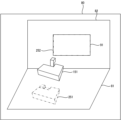
図1は、実施形態の情報処理装置による設置支援対象の投影装置10の一例を示す模式図である。
<An example of the
FIG. 1 is a schematic diagram illustrating an example of a
実施形態の情報処理装置は、例えば投影装置10の配置支援に用いることができる。投影装置10は、投影部1と、制御装置4と、操作受付部2と、を備える。投影部1は、例えば液晶プロジェクタ又はLCOS(Liquid Crystal On Silicon)を用いたプロジェクタ等によって構成される。以下では、投影部1が液晶プロジェクタであるものとして説明する。
The information processing device of the embodiment can be used, for example, to support placement of the
制御装置4は、投影装置10による投影の制御を行う制御装置である。制御装置4は、各種のプロセッサにより構成される制御部と、各部と通信するための通信インタフェース(図示省略)と、ハードディスク、SSD(Solid State Drive)、又はROM(Read Only Memory)等のメモリ4aと、を含む装置であり、投影部1を統括制御する。
The
制御装置4の制御部の各種のプロセッサとしては、プログラムを実行して各種処理を行う汎用的なプロセッサであるCPU(Central Processing Unit)、FPGA(Field Programmable Gate Array)等の製造後に回路構成を変更可能なプロセッサであるプログラマブルロジックデバイス(Programmable Logic Device:PLD)、又はASIC(Application Specific Integrated Circuit)等の特定の処理を実行させるために専用に設計された回路構成を有するプロセッサである専用電気回路等が含まれる。
Various processors in the control unit of the
これら各種のプロセッサの構造は、より具体的には、半導体素子等の回路素子を組み合わせた電気回路である。制御装置4の制御部は、各種のプロセッサのうちの1つで構成されてもよいし、同種又は異種の2つ以上のプロセッサの組み合わせ(例えば、複数のFPGAの組み合わせ又はCPUとFPGAの組み合わせ)で構成されてもよい。
More specifically, the structure of these various processors is an electric circuit that combines circuit elements such as semiconductor elements. The control unit of the
操作受付部2は、利用者からの各種の操作を受け付けることにより、利用者からの指示を検出する。操作受付部2は、制御装置4に設けられたボタン、キー、ジョイスティック等であってもよいし、制御装置4の遠隔操作を行うリモートコントローラからの信号を受け付ける受信部等であってもよい。
The
被投影物6は、投影部1によって投影画像が表示される投影面を有する、スクリーンや壁などの物体である。図1に示す例では、被投影物6は、被投影物6の投影面は矩形の平面である。図1における被投影物6の上下左右が、実際の被投影物6の上下左右であるとする。
The
一点鎖線で図示する投影範囲11は、被投影物6のうち、投影部1により投影光が照射される領域である。図1に示す例では、投影範囲11は矩形である。投影範囲11は、投影部1により投影が可能な投影可能範囲の一部又は全部である。
A
なお、投影部1、制御装置4、及び操作受付部2は、例えば一個の装置により実現される(例えば図3,図4参照)。又は、投影部1、制御装置4、及び操作受付部2は、互いに通信を行うことにより連携する、それぞれ別の装置であってもよい。
Note that the
<図1に示す投影部1の内部構成>
図2は、図1に示す投影部1の内部構成の一例を示す模式図である。
<Internal configuration of
FIG. 2 is a schematic diagram showing an example of the internal configuration of the
図2に示すように、投影部1は、光源21と、光変調部22と、投影光学系23と、制御回路24と、を備える。
As shown in FIG. 2, the
光源21は、レーザ又はLED(Light Emitting Diode)等の発光素子を含み、例えば白色光を出射する。
The
光変調部22は、光源21から出射されて図示省略の色分離機構によって赤、青、緑の3色に分離された各色光を、画像情報に基づいて変調して各色画像を出射する3つの液晶パネルによって構成される。この3つの液晶パネルにそれぞれ赤、青、緑のフィルタを搭載し、光源21から出射された白色光を、各液晶パネルにて変調して各色画像を出射させてもよい。
The
投影光学系23は、光源21及び光変調部22からの光が入射されるものであり、少なくとも1つのレンズを含む、例えばリレー光学系によって構成されている。投影光学系23を通過した光は被投影物6に投影される。
The projection
被投影物6のうち、光変調部22の全範囲を透過する光が照射される領域が、投影部1により投影が可能な投影可能範囲となる。この投影可能範囲のうち、光変調部22から実際に透過する光が照射される領域が投影範囲11となる。例えば、光変調部22のうち光が透過する領域の大きさ、位置、及び形状を制御することにより、投影可能範囲において、投影範囲11の大きさ、位置、及び形状が変化する。
The area of the object to be projected 6 that is irradiated with light that passes through the entire range of the
制御回路24は、制御装置4から入力される表示用データに基づいて、光源21、光変調部22、及び投影光学系23を制御することにより、被投影物6にこの表示用データに基づく画像を投影させる。制御回路24に入力される表示用データは、赤表示用データと、青表示用データと、緑表示用データとの3つによって構成される。
The
また、制御回路24は、制御装置4から入力される命令に基づいて、投影光学系23を変化させることにより、投影部1の投影範囲11(図1参照)の拡大や縮小を行う。また、制御装置4は、操作受付部2によって受け付けられた利用者からの操作に基づいて投影光学系23を変化させることにより、投影部1の投影範囲11の移動を行ってもよい。
Furthermore, the
また、投影装置10は、投影光学系23のイメージサークルを維持しつつ、投影範囲11を機械的又は光学的に移動させるシフト機構を備える。投影光学系23のイメージサークルは、投影光学系23に入射した投影光が、光量落ち、色分離、周辺湾曲などの点から適正に投影光学系23を通過する領域である。
Furthermore, the
シフト機構は、光学系シフトを行う光学系シフト機構と、電子シフトを行う電子シフト機構と、の少なくともいずれかにより実現される。 The shift mechanism is realized by at least one of an optical system shift mechanism that shifts the optical system and an electronic shift mechanism that shifts the electronic system.
光学系シフト機構は、例えば、投影光学系23を光軸に垂直な方向に移動させる機構(例えば図3,図4参照)、又は、投影光学系23を移動させる代わりに光変調部22を光軸に垂直な方向に移動させる機構である。また、光学系シフト機構は、投影光学系23の移動と光変調部22の移動とを組み合わせて行うものであってもよい。
The optical system shift mechanism is, for example, a mechanism that moves the projection
電子シフト機構は、光変調部22において光を透過させる範囲を変化させることによる疑似的な投影範囲11のシフトを行う機構である。
The electronic shift mechanism is a mechanism that performs a pseudo shift of the
また、投影装置10は、投影光学系23のイメージサークルとともに投影範囲11を移動させる投影方向変更機構を備えてもよい。投影方向変更機構は、機械的な回転で投影部1の向きを変更することにより、投影部1の投影方向を変化させる機構である(例えば図3,図4参照)。
Furthermore, the
<投影装置10の機械的構成>
図3は、投影装置10の外観構成を示す模式図である。図4は、図3に示す投影装置10の光学ユニット106の断面模式図である。図4は、図3に示す本体部101から出射される光の光路に沿った面での断面を示している。
<Mechanical configuration of
FIG. 3 is a schematic diagram showing the external configuration of the
図3に示すように、投影装置10は、本体部101と、本体部101から突出して設けられた光学ユニット106と、を備える。図3に示す構成において、操作受付部2と、制御装置4と、投影部1における光源21、光変調部22、及び制御回路24と、は本体部101に設けられる。投影部1における投影光学系23は光学ユニット106に設けられる。
As shown in FIG. 3, the
光学ユニット106は、本体部101に支持される第1部材102と、第1部材102に支持された第2部材103と、を備える。
The
なお、第1部材102と第2部材103は一体化された部材であってもよい。光学ユニット106は、本体部101に着脱自在に構成(換言すると交換可能に構成)されていてもよい。
Note that the
本体部101は、光学ユニット106と連結される部分に光を通すための開口15a(図4参照)が形成された筐体15(図4参照)を有する。
The
本体部101の筐体15の内部には、図3に示すように、光源21と、光源21から出射される光を入力画像データに基づいて空間変調して画像を生成する光変調部22(図2参照)を含む光変調ユニット12と、が設けられている。
As shown in FIG. 3, inside the
光源21から出射された光は、光変調ユニット12の光変調部22に入射され、光変調部22によって空間変調されて出射される。
The light emitted from the
図4に示すように、光変調ユニット12によって空間変調された光によって形成される画像は、筐体15の開口15aを通過して光学ユニット106に入射され、投影対象物としての被投影物6に投影されて、画像G1が観察者から視認可能となる。
As shown in FIG. 4, the image formed by the light spatially modulated by the
図4に示すように、光学ユニット106は、本体部101の内部と繋がる中空部2Aを有する第1部材102と、中空部2Aと繋がる中空部3Aを有する第2部材103と、中空部2Aに配置された第1光学系121及び反射部材122と、中空部3Aに配置された第2光学系31、反射部材32、第3光学系33、及びレンズ34と、シフト機構105と、投影方向変更機構104と、を備える。
As shown in FIG. 4, the
第1部材102は、断面外形が一例として矩形の部材であり、開口2aと開口2bが互いに垂直な面に形成されている。第1部材102は、本体部101の開口15aと対面する位置に開口2aが配置される状態にて、本体部101によって支持されている。本体部101の光変調ユニット12の光変調部22から射出された光は、開口15a及び開口2aを通って第1部材102の中空部2Aに入射される。
The
本体部101から中空部2Aに入射される光の入射方向を方向X1と記載し、方向X1の逆方向を方向X2と記載し、方向X1と方向X2を総称して方向Xと記載する。また、図4において、紙面手前から奥に向かう方向とその逆方向を方向Zと記載する。方向Zのうち、紙面手前から奥に向かう方向を方向Z1と記載し、紙面奥から手前に向かう方向を方向Z2と記載する。
The direction of incidence of light entering the
また、方向X及び方向Zに垂直な方向を方向Yと記載し、方向Yのうち、図4において上に向かう方向を方向Y1と記載し、図4において下に向かう方向を方向Y2と記載する。図4の例では方向Y2が鉛直方向となるように投影装置10が配置されている。
Further, the direction perpendicular to the direction X and the direction Z is described as a direction Y, the direction going upward in FIG. . In the example of FIG. 4, the
図2に示した投影光学系23は、第1光学系121、反射部材122、第2光学系31、反射部材32、第3光学系33、及びレンズ34により構成される。図4には、この投影光学系23の光軸Kが示されている。第1光学系121、反射部材122、第2光学系31、反射部材32、第3光学系33、及びレンズ34は、光変調部22側からこの順に光軸Kに沿って配置されている。
The projection
第1光学系121は、少なくとも1つのレンズを含み、本体部101から第1部材102に入射された方向X1に進む光を反射部材122に導く。
The first
反射部材122は、第1光学系121から入射された光を方向Y1に反射させる。反射部材122は、例えばミラー等によって構成される。第1部材102には、反射部材122にて反射した光の光路上に開口2bが形成されており、この反射した光は開口2bを通過して第2部材103の中空部3Aへと進む。
The reflecting
第2部材103は、断面外形が略T字状の部材であり、第1部材102の開口2bと対面する位置に開口3aが形成されている。第1部材102の開口2bを通過した本体部101からの光は、この開口3aを通って第2部材103の中空部3Aに入射される。なお、第1部材102や第2部材103の断面外形は任意であり、上記のものには限定されない。
The
第2光学系31は、少なくとも1つのレンズを含み、第1部材102から入射された光を、反射部材32に導く。
The second
反射部材32は、第2光学系31から入射される光を方向X2に反射させて第3光学系33に導く。反射部材32は、例えばミラー等によって構成される。
The reflecting
第3光学系33は、少なくとも1つのレンズを含み、反射部材32にて反射された光をレンズ34に導く。
The third
レンズ34は、第2部材103の方向X2側の端部に形成された開口3cを塞ぐ形でこの端部に配置されている。レンズ34は、第3光学系33から入射された光を被投影物6に投影する。
The
投影方向変更機構104は、第1部材102に対して第2部材103を回転自在に連結する回転機構である。この投影方向変更機構104によって、第2部材103は、方向Yに延びる回転軸(具体的には光軸K)の回りに回転自在に構成されている。なお、投影方向変更機構104は、光学系を回転させることができればよく、図4に示した配置位置に限定されない。また、回転機構の数も1つに限らず、複数設けられていてもよい。
The projection
シフト機構105は、投影光学系の光軸K(換言すると光学ユニット106)をその光軸Kに垂直な方向(図4の方向Y)に移動させるための機構である。具体的には、シフト機構105は、第1部材102の本体部101に対する方向Yの位置を変更することができるように構成されている。シフト機構105は、手動にて第1部材102を移動させるものの他、電動にて第1部材102を移動させるものであってもよい。
The
図4は、シフト機構105によって第1部材102が方向Y1側に最大限移動された状態を示している。この図4に示す状態から、シフト機構105によって第1部材102が方向Y2に移動することで、光変調部22によって形成される画像の中心(換言すると表示面の中心)と光軸Kとの相対位置が変化して、被投影物6に投影されている画像G1を方向Y2にシフト(平行移動)させることができる。
FIG. 4 shows a state in which the
なお、シフト機構105は、光学ユニット106を方向Yに移動させる代わりに、光変調部22を方向Yに移動させる機構であってもよい。この場合でも、被投影物6に投影されている画像G1を方向Y2に移動させることができる。
Note that the
<実施形態の情報処理装置50>
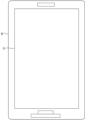
図5は、実施形態の情報処理装置50の一例を示す図である。実施形態の情報処理装置50は、タッチパネル51を有するタブレット端末である。タッチパネル51は、タッチ操作が可能なディスプレイである。例えば、情報処理装置50の利用者は、投影装置10を設置して投影を行う空間(例えば部屋)に情報処理装置50を持ち込む。情報処理装置50は、その空間への投影装置10の設置を支援するための設置支援画像をタッチパネル51により表示する。
<
FIG. 5 is a diagram illustrating an example of the
具体的には、情報処理装置50は、投影装置10を設置して投影を行う空間を撮像して得られた第1画像に、仮想的な投影面である第1仮想投影面と、1つ目の仮想的な投影装置である第1仮想投影装置又は第1仮想投影装置の第1設置可能範囲と、2つ目の仮想的な投影装置である第2仮想投影装置又は第2仮想投影装置の第2設置可能範囲と、を重畳した第2画像を表示することで、第1仮想投影装置及び第2仮想投影装置を比較しながら投影装置10の設置を検討することができる。第1仮想投影装置及び第2仮想投影装置は、投影装置10の候補を仮想的に表すものである。ユーザは、第1仮想投影装置及び第2仮想投影装置として、互いに異なる機種の投影装置を指定可能である。また、ユーザは、第1仮想投影装置及び第2仮想投影装置として、互いに異なるメーカーの投影装置を指定可能であってもよい。
Specifically, the
<情報処理装置50のハードウェア構成>
図6は、実施形態の情報処理装置50のハードウェア構成の一例を示す図である。図5に示した情報処理装置50は、例えば、図6に示すように、プロセッサ61と、メモリ62と、通信インタフェース63と、ユーザインタフェース64と、センサ65と、を備える。プロセッサ61、メモリ62、通信インタフェース63、ユーザインタフェース64、及びセンサ65は、例えばバス69によって接続される。
<Hardware configuration of
FIG. 6 is a diagram illustrating an example of the hardware configuration of the
プロセッサ61は、信号処理を行う回路であり、例えば情報処理装置50の全体の制御を司るCPUである。なお、プロセッサ61は、FPGAやDSP(Digital Signal Processor)などの他のデジタル回路により実現されてもよい。また、プロセッサ61は、複数のデジタル回路を組み合わせて実現されてもよい。
The
メモリ62には、例えばメインメモリ及び補助メモリが含まれる。メインメモリは、例えばRAM(Random Access Memory)である。メインメモリは、プロセッサ61のワークエリアとして使用される。
The
補助メモリは、例えば磁気ディスク、フラッシュメモリなどの不揮発性メモリである。補助メモリには、情報処理装置50を動作させる各種のプログラムが記憶されている。補助メモリに記憶されたプログラムは、メインメモリにロードされてプロセッサ61によって実行される。
The auxiliary memory is, for example, nonvolatile memory such as a magnetic disk or flash memory. Various programs for operating the
また、補助メモリは、情報処理装置50から取り外し可能な可搬型のメモリを含んでもよい。可搬型のメモリには、USB(Universal Serial Bus)フラッシュドライブやSD(Secure Digital)メモリカードなどのメモリカードや、外付けハードディスクドライブなどがある。
Further, the auxiliary memory may include a portable memory that is removable from the
通信インタフェース63は、情報処理装置50の外部の装置との間で通信を行う通信インタフェースである。通信インタフェース63は、有線により通信を行う有線通信インタフェースと、無線により通信を行う無線通信インタフェースと、の少なくともいずれかを含む。通信インタフェース63は、プロセッサ61によって制御される。
The
ユーザインタフェース64は、例えば、利用者からの操作入力を受け付ける入力デバイスや、利用者へ情報を出力する出力デバイスなどを含む。入力デバイスは、例えばキー(例えばキーボード)やリモコンなどにより実現することができる。出力デバイスは、例えばディスプレイやスピーカなどにより実現することができる。図5に示した情報処理装置50においては、タッチパネル51によって入力デバイス及び出力デバイスが実現されている。ユーザインタフェース64は、プロセッサ61によって制御される。
The
センサ65は、撮像光学系及び撮像素子を有し撮像が可能な撮像装置や、情報処理装置50の周辺の空間を3次元的に認識可能な空間認識センサなどを含む。撮像装置は、例えば図5に示した情報処理装置50の裏面に設けられた撮像装置を含む。
The
空間認識センサは、一例としては、レーザ光を照射し、照射したレーザ光が物体に当たって跳ね返ってくるまでの時間を計測し、物体までの距離や方向を測定するLIDAR(Light Detection and Ranging)である。ただし、空間認識センサは、これに限らず、電波を発射するレーダや、超音波を発射する超音波センサなど各種のセンサとすることができる。 An example of a spatial recognition sensor is LIDAR (Light Detection and Ranging) that irradiates a laser beam, measures the time until the irradiated laser beam hits an object and bounces back, and measures the distance and direction to the object. . However, the spatial recognition sensor is not limited to this, and may be various sensors such as a radar that emits radio waves or an ultrasonic sensor that emits ultrasonic waves.
情報処理装置50は、例えば下記のスクリーン優先モード、プロジェクタ優先第1モード、プロジェクタ優先第2モード、プロジェクタ優先第3モード、及び機種検索モードの少なくともいずれかの処理を実行する。
The
(スクリーン優先モード)
図7は、スクリーン優先モードにおける情報処理装置50の処理の一例を示すフローチャートである。図8~図13は、図7に示す処理において情報処理装置50が表示する画像の一例である。例えば、図7に示す処理の開始時に、情報処理装置50は、図8に示す物理空間画像80を表示している。物理空間画像80は、例えば、情報処理装置50がセンサ65として備える撮像装置による撮像で得られた画像をリアルタイムに示すスルー画像(ライブビュー画像)である。物理空間画像80は、本発明の第1画像の一例である。
(Screen priority mode)
FIG. 7 is a flowchart illustrating an example of processing of the
また、情報処理装置50は、物理空間画像80が示す物理空間を3次元的に認識している。この空間認識には、例えば情報処理装置50のセンサ65に含まれる空間認識センサを用いられる。物理空間画像80が示す物理空間には、床81及び壁82が存在している。ここでは、床81に投影装置10を設置し、壁82に対して投影を行うことを想定するものとする。
Furthermore, the
まず、情報処理装置50は、第1仮想投影面の位置及びサイズの指定をユーザから受け付ける(ステップS71)。第1仮想投影面は、例えば上記の投影範囲11を仮想的に示すものである。第1仮想投影面の位置は、例えば、第1仮想投影面の中心位置(投影中心の位置)である。例えば、第1仮想投影面の位置は、ユーザが物理空間画像80における1点を第1仮想投影面の中心位置として指示することにより、物理空間画像80の2次元座標として指定される。情報処理装置50は、指定された2次元座標を、物理空間画像80が示す物理空間の認識結果に基づいて3次元座標に変換することにより、第1仮想投影面の3次元位置として受け付ける。第1仮想投影面のサイズは、例えば対角線の長さ=x[inch]などの物理空間における実際の距離を用いて指定される。
First, the
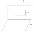
次に、情報処理装置50は、ステップS71によって受け付けた指定に基づいて、第1仮想投影面を物理空間画像80に重畳して表示する(ステップS72)。具体的には、情報処理装置50は、物理空間画像80が示す物理空間における第1仮想投影面の3次元領域を計算し、物理空間画像80が示す物理空間の認識結果に基づいてその3次元領域を物理空間画像80に対応する2次元領域に変換し、変換した領域を示す画像を第1仮想投影面として物理空間画像80に重畳する。例えば、情報処理装置50は、図9に示すように、物理空間画像80に第1仮想投影面91を重畳した画像を表示する。
Next, the
次に、情報処理装置50は、投影装置10の機種の複数の選択肢の中から、第1仮想投影装置の機種の指定をユーザから受け付ける(ステップS73)。次に、情報処理装置50は、現在の第1仮想投影面91の位置及びサイズと、ステップS73によって第1仮想投影装置の機種として指定を受け付けた機種で設定可能な投写比及びレンズシフト量に基づいて、例えば多面体で表される第1設置可能範囲の位置及びサイズを計算し、算出した位置及びサイズの第1設置可能範囲を物理空間画像80に重畳して表示する(ステップS74)。
Next, the
具体的には、情報処理装置50は、物理空間画像80が示す物理空間における第1設置可能範囲の3次元領域を計算し、物理空間画像80が示す物理空間の認識結果に基づいてその3次元領域を物理空間画像80に対応する2次元領域に変換し、変換した領域を示す画像を第1設置可能範囲として物理空間画像80に重畳する。例えば、情報処理装置50は、図10に示すように、物理空間画像80に第1仮想投影面91及び第1設置可能範囲92を重畳した画像を表示する。
Specifically, the
次に、情報処理装置50は、投影装置10の機種の複数の選択肢の中から、第2仮想投影装置の機種の指定をユーザから受け付ける(ステップS75)。次に、情報処理装置50は、現在の第1仮想投影面91の位置及びサイズと、ステップS75によって第2仮想投影装置の機種として指定を受け付けた機種で設定可能な投写比及びレンズシフト量と、に基づいて、例えば多面体で表される第2設置可能範囲の位置及びサイズを計算し、算出した位置及びサイズの第2設置可能範囲を物理空間画像80に重畳して表示する(ステップS76)。
Next, the
具体的には、情報処理装置50は、物理空間画像80が示す物理空間における第2設置可能範囲の3次元領域を計算し、物理空間画像80が示す物理空間の認識結果に基づいてその3次元領域を物理空間画像80に対応する2次元領域に変換し、変換した領域を示す画像を第2設置可能範囲として物理空間画像80に重畳する。例えば、情報処理装置50は、図11に示すように、物理空間画像80に第1仮想投影面91、第1設置可能範囲92、及び第2設置可能範囲93を重畳した画像を表示する。
Specifically, the
これにより、ユーザは、投写比やレンズシフト量などのパラメータの設定範囲が異なる投影装置同士(例えば第1仮想投影装置と第2仮想投影装置)について、所望の投影面(例えば第1仮想投影面91)に対する設置可能な範囲(例えば第1設置可能範囲92や第2設置可能範囲93)を視覚的に比較でき、適切な投影装置の機種の選定が容易になる。
As a result, the user can select a desired projection surface (for example, the first virtual projection surface) for projection devices (for example, the first virtual projection device and the second virtual projection device) that have different setting ranges for parameters such as the projection ratio and the amount of lens shift. 91), the installable range (for example, the first
次に、情報処理装置50は、第1仮想投影面91のサイズの変更指示をユーザから受け付けたか否かを判断する(ステップS77)。第1仮想投影面91のサイズの変更指示を受け付けた場合(ステップS77:Yes)は、情報処理装置50は、第1仮想投影面91のサイズを変更し、サイズを変更した第1仮想投影面91を物理空間画像80に重畳して表示する(ステップS78)。
Next, the
また、情報処理装置50は、現在の第1仮想投影面91の位置及びサイズと、ステップS73によって第1仮想投影装置の機種として指定を受け付けた機種で設定可能な投写比及びレンズシフト量と、に基づいて、第1設置可能範囲92の位置及びサイズを再計算する。また、情報処理装置50は、現在の第1仮想投影面91の位置及びサイズと、ステップS75によって第2仮想投影装置の機種として指定を受け付けた機種で設定可能な投写比及びレンズシフト量と、に基づいて、第2設置可能範囲93の位置及びサイズを再計算する。そして、情報処理装置50は、再計算した位置及びサイズの第1設置可能範囲92及び第2設置可能範囲93を物理空間画像80に重畳して表示し(ステップS79)、ステップS77へ戻る。
The
これにより、ユーザは、第1仮想投影面91のサイズの変更に対する、第1設置可能範囲92及び第2設置可能範囲93の設置可能範囲の位置やサイズの変化を視覚的に把握でき、適切な機種の選定が容易になる。例えば、第1仮想投影面91のサイズをx[inch]からy[inch]に変更(x>y)することを指示する変更指示が行われたとする。この場合、例えば図12に示すように、第1仮想投影面91の縮小に連動して、第1設置可能範囲92及び第2設置可能範囲93が縮小するとともに、第1仮想投影面91からの第1設置可能範囲92及び第2設置可能範囲93の距離が小さくなる。
As a result, the user can visually understand the changes in the position and size of the first
ステップS77において、第1仮想投影面91のサイズの変更指示を受け付けていない場合(ステップS77:No)は、情報処理装置50は、第1仮想投影面91の位置の変更指示を受け付けたか否かを判断する(ステップS80)。第1仮想投影面91の位置の変更指示を受け付けた場合(ステップS80:Yes)は、情報処理装置50は、第1仮想投影面91の位置を変更し、位置を変更した第1仮想投影面91を物理空間画像に重畳して表示する(ステップS81)。
In step S77, if an instruction to change the size of the first
また、情報処理装置50は、ステップS79と同様に、第1設置可能範囲92及び第2設置可能範囲93のそれぞれの位置及びサイズを再計算し、再計算した位置及びサイズの第1設置可能範囲92及び第2設置可能範囲93を物理空間画像80に重畳して表示し(ステップS82)、ステップS77へ戻る。
Further, similarly to step S79, the
これにより、ユーザは、第1仮想投影面91の位置の変更に対する、第1設置可能範囲92及び第2設置可能範囲93の設置可能範囲の位置やサイズの変化を視覚的に把握でき、適切な機種の選定が容易になる。例えば、第1仮想投影面91の位置を第1仮想投影面91に向かって左方向に移動することを指示する変更指示が行われたとする。この場合、例えば図13に示すように、第1仮想投影面91の左方向への移動に連動して、第1設置可能範囲92及び第2設置可能範囲93が左方向へ移動する。
As a result, the user can visually grasp the changes in the position and size of the first
ステップS80において、第1仮想投影面91の位置の変更指示を受け付けていない場合(ステップS80:No)は、情報処理装置50は、ステップS77へ戻る。
In step S80, if the instruction to change the position of the first
このように、スクリーン優先モードにおいて、情報処理装置50は、第1仮想投影面91と、第1仮想投影装置の第1設置可能範囲92と、第2仮想投影装置の第2設置可能範囲93と、を含む第2画像を表示する。また、情報処理装置50は、第1仮想投影面91の位置及びサイズに基づいて、第1仮想投影装置の第1設置可能範囲92及び第2仮想投影装置の第2設置可能範囲93を設定する。また、情報処理装置50は、第1仮想投影面91の位置及びサイズのいずれかに基づいて、第1仮想投影装置の第1設置可能範囲92及び第2仮想投影装置の第2設置可能範囲93を設定してもよい。
In this way, in the screen priority mode, the
また、スクリーン優先モードにおいて、情報処理装置50は、第1仮想投影面91の位置及びサイズの少なくともいずれかが変更された場合、第1仮想投影装置の第1設置可能範囲92及び第2仮想投影装置の第2設置可能範囲93を再設定する。
Furthermore, in the screen priority mode, when at least one of the position and size of the first
(プロジェクタ優先第1モード)
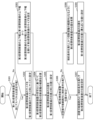
図14は、プロジェクタ優先第1モードにおける情報処理装置50の処理の一例を示すフローチャートである。図15~図19は、図14に示す処理において情報処理装置50が表示する画像の一例である。スクリーン優先モードの場合と同様に、情報処理装置50は、図14に示す処理の開始時に、図8に示した物理空間画像80を表示している。また、情報処理装置50は、物理空間画像80が示す物理空間を3次元的に認識している。
(Projector priority 1st mode)
FIG. 14 is a flowchart illustrating an example of the processing of the
まず、情報処理装置50は、第1仮想投影装置の位置と、第1仮想投影面91の位置(投影中心の位置)と、の指定をユーザから受け付ける(ステップS141)。第1仮想投影装置の位置は、例えば第1仮想投影装置の投影レンズの前玉の位置である。例えば、情報処理装置50は、図15に示す第1仮想投影装置の位置P1と第1仮想投影面91の位置P2との指定を受け付ける。情報処理装置50は、指定を受け付けた位置P1,P2に基づいて、位置P1,P2の間の距離である投影距離D1を計算する。
First, the
次に、情報処理装置50は、投影装置10の機種の複数の選択肢の中から、第1仮想投影装置の機種の指定をユーザから受け付ける(ステップS142)。次に、情報処理装置50は、投影距離D1と、ステップS142によって指定を受け付けた第1仮想投影装置の機種に応じた投写比と、に基づいて、第1仮想投影面91のサイズを計算する(ステップS143)。
Next, the
また、情報処理装置50は、ステップS142によって指定を受け付けた第1仮想投影装置の3次元モデルである第1仮想投影装置151と第1仮想投影面91とを物理空間画像80に重畳して表示する(ステップS144)。例えば、情報処理装置50は、図16に示すように、物理空間画像80に第1仮想投影装置151及び第1仮想投影面91を重畳した画像を表示する。
The
第1仮想投影装置151は、第1仮想投影装置151の投影レンズの前玉が図15に示した位置P1となるように配置される。第1仮想投影面91は、第1仮想投影面91の中心位置が図15に示した位置P2となるように配置される。また、第1仮想投影面91のサイズは、ステップS143によって計算されたサイズである。
The first
次に、情報処理装置50は、投影装置10の機種の複数の選択肢の中から、第2仮想投影装置の機種の指定を受け付ける(ステップS145)。次に、情報処理装置50は、第1仮想投影面91の位置及びサイズと、ステップS145によって第2仮想投影装置の機種として指定を受け付けた機種で設定可能な投写比及びレンズシフト量と、に基づいて、第2仮想投影装置を設置可能な第2設置可能範囲93の位置及びサイズを計算し、位置及びサイズを計算した第2設置可能範囲93を物理空間画像80に重畳して表示する(ステップS146)。例えば、情報処理装置50は、図17に示すように、物理空間画像80に第1仮想投影装置151、第1仮想投影面91、及び第2設置可能範囲93を重畳した画像を表示する。
Next, the
これにより、ユーザは、暫定的に仮想配置した第1仮想投影装置151に対して、比較対象とする第2仮想投影装置の第2設置可能範囲93を視覚的に把握でき、適切な機種の選定が容易になる。
As a result, the user can visually grasp the second
次に、情報処理装置50は、第1仮想投影装置151の位置の変更指示をユーザから受け付けたか否かを判断する(ステップS147)。第1仮想投影装置151の位置の変更指示を受け付けた場合(ステップS147:Yes)は、情報処理装置50は、第1仮想投影装置151の位置を変更し、位置を変更した第1仮想投影装置151を物理空間画像80に重畳して表示する(ステップS148)。
Next, the
また、情報処理装置50は、現在の第1仮想投影装置151の位置と、ステップS142によって第1仮想投影装置の機種として指定を受け付けた機種で設定可能な投写比及びレンズシフト量と、に基づいて、第1仮想投影面91の位置及びサイズを再計算する。そして、情報処理装置50は、再計算した位置及びサイズの第1仮想投影面91を物理空間画像80に重畳して表示する(ステップS149)。
Further, the
次に、情報処理装置50は、再計算した第1仮想投影面91の位置及びサイズと、ステップS145によって第2仮想投影装置の機種として指定を受け付けた機種で設定可能な投写比及びレンズシフト量と、に基づいて、第2設置可能範囲93の位置及びサイズを再計算する。そして、情報処理装置50は、再計算した位置及びサイズの第2設置可能範囲93を物理空間画像80に重畳して表示し(ステップS150)、ステップS147へ戻る。
Next, the
これにより、ユーザは、第1仮想投影面91のサイズの変更に対する、比較対象とする機種(第2仮想投影装置)の第2設置可能範囲93の位置及びサイズの変化を視覚的に把握でき、適切な機種の選定が容易になる。例えば、第1仮想投影装置151を第1仮想投影面91に近づけることを指示する変更指示が行われたとする。この場合、例えば図18に示すように、第1仮想投影装置151の第1仮想投影面91の側への移動に連動して、第1仮想投影面91が縮小し、第2設置可能範囲93が第1仮想投影面91の側へ移動し、第2設置可能範囲93が縮小する。
Thereby, the user can visually grasp the change in the position and size of the second
ステップS147において、第1仮想投影装置151の位置の変更指示を受け付けていない場合(ステップS147:No)は、情報処理装置50は、第1仮想投影面91の位置の変更指示をユーザから受け付けたか否かを判断する(ステップS151)。第1仮想投影面91の位置の変更指示を受け付けた場合(ステップS151:Yes)は、情報処理装置50は、第1仮想投影面91の位置を変更し、位置を変更した第1仮想投影面91を物理空間画像80に重畳して表示する(ステップS152)。
In step S147, if the instruction to change the position of the first
次に、情報処理装置50は、現在の第1仮想投影面91の位置及びサイズと、ステップS145によって第2仮想投影装置の機種として指定を受け付けた機種で設定可能な投写比及びレンズシフト量と、に基づいて、第2設置可能範囲93の位置及びサイズを再計算する。そして、情報処理装置50は、再計算した位置及びサイズの第2設置可能範囲93を物理空間画像80に重畳して表示し(ステップS153)、ステップS147へ戻る。
Next, the
これにより、ユーザは、第1仮想投影面91の位置の変更に対する、比較対象とする機種(第2仮想投影装置)の第2設置可能範囲93の位置の変化を視覚的に把握でき、適切な機種の選定が容易になる。例えば、第1仮想投影面91の位置を第1仮想投影面91に向かって左方向に移動することを指示する変更指示が行われたとする。この場合、例えば図19に示すように、第1仮想投影面91の左方向への移動に連動して第2設置可能範囲93が左方向へ移動する。
This allows the user to visually grasp the change in the position of the second
ステップS151において、第1仮想投影面91の位置の変更指示を受け付けていない場合(ステップS151:No)は、情報処理装置50は、ステップS147へ戻る。
In step S151, if the instruction to change the position of the first
なお、情報処理装置50は、ステップS147の後に、第1仮想投影装置151の投写比の変更指示をユーザから受け付けてもよい。例えば、情報処理装置50は、第1仮想投影装置151の投写比を減少させる変更指示を受け付けた場合、第1仮想投影装置151の位置は維持しつつ第1仮想投影面91を縮小する。この場合、情報処理装置50は、第2設置可能範囲93を第1仮想投影面91の方へ移動させ、第2設置可能範囲93を縮小する。
Note that the
このように、プロジェクタ優先第1モードにおいて、情報処理装置50は、第1仮想投影面91と、第1仮想投影装置151と、第2仮想投影装置の第2設置可能範囲93と、を含む第2画像を表示する。また、情報処理装置50は、第1仮想投影装置151の位置に基づいて、第1仮想投影面91の位置及びサイズの少なくともいずれかを設定し、設定した第1仮想投影面91の位置及びサイズの少なくともいずれかに基づいて、第2仮想投影装置の第2設置可能範囲93を設定する。
As described above, in the first projector priority mode, the
また、プロジェクタ優先第1モードにおいて、情報処理装置50は、第1仮想投影装置151の位置又はパラメータが変更された場合、第1仮想投影面91の位置及びサイズの少なくともいずれかと、第2仮想投影装置の第2設置可能範囲93と、を再設定する。また、情報処理装置50は、第1仮想投影面91の位置が変更された場合、第2仮想投影装置の第2設置可能範囲93を再設定する。
Furthermore, in the first projector priority mode, when the position or parameters of the first
(プロジェクタ優先第2モード)
図20及び図21は、プロジェクタ優先第2モードにおける情報処理装置50の処理の一例を示すフローチャートである。図22~図26は、図20,図21に示す処理において情報処理装置50が表示する画像の一例である。スクリーン優先モードの場合と同様に、情報処理装置50は、図20に示す処理の開始時に、図8に示した物理空間画像80を表示している。また、情報処理装置50は、物理空間画像80が示す物理空間を3次元的に認識している。
(Projector priority 2nd mode)
20 and 21 are flowcharts illustrating an example of the processing of the
まず、情報処理装置50は、図14に示したステップS141と同様に、第1仮想投影装置151の位置と、第1仮想投影面91の位置(投影中心の位置)と、の指定をユーザから受け付ける(ステップS201)。例えば、情報処理装置50は、図15に示した第1仮想投影装置の位置P1と第1仮想投影面91の位置P2との指定を受け付ける。
First, the
次に、情報処理装置50は、図14に示したステップS142と同様に、投影装置10の機種の複数の選択肢の中から、第1仮想投影装置の機種の指定をユーザから受け付ける(ステップS202)。
Next, the
次に、情報処理装置50は、ステップS201により指定を受け付けた第1仮想投影装置151の位置に基づいて、第1仮想投影装置151においてレンズシフトを行わない場合の投影中心の位置を計算する(ステップS203)。例えば、情報処理装置50は、図22に示すように、第1仮想投影装置151においてレンズシフトを行わない場合(レンズシフト量=0の場合)の投影中心の位置P3を計算する。また、情報処理装置50は、位置P1,P3の間の距離である投影距離D2を計算する。
Next, the
次に、情報処理装置50は、投影距離D2と、ステップS202によって指定を受け付けた第1仮想投影装置の機種に応じた投写比と、に基づいて、第1仮想投影面91のサイズを計算する(ステップS204)。例えば、情報処理装置50は、第1仮想投影装置151がレンズシフトを行わずに位置P3へ投影を行った場合の投影面のサイズを、第1仮想投影面91のサイズとして計算する。
Next, the
次に、情報処理装置50は、第1仮想投影装置151と第1仮想投影面91を物理空間画像80に投影して表示する(ステップS205)。例えば、情報処理装置50は、図23に示すように、物理空間画像80に第1仮想投影装置151及び第1仮想投影面91を重畳した画像を表示する。第1仮想投影装置151は、ステップS202によって第1仮想投影装置の機種として指定を受け付けた機種の3次元モデルである。
Next, the
第1仮想投影装置151は、第1仮想投影装置151の投影レンズの前玉が図22に示した位置P1となるように配置される。第1仮想投影面91は、第1仮想投影面91の中心位置が図22に示した位置P2となるように配置される。また、第1仮想投影面91のサイズは、ステップS204によって計算されたサイズである。
The first
また、情報処理装置50は、図24に示すように、第1仮想投影装置151の底面に垂直な軸をY軸、第1仮想投影装置151の投影方向をZ軸、Y軸及びZ軸と直交する軸をX軸とする座標系を設定する。
Further, as shown in FIG. 24, the
次に、情報処理装置50は、投影装置10の機種の複数の選択肢の中から、第2仮想投影装置の機種の指定を受け付ける(ステップS206)。次に、情報処理装置50は、ステップS206によって第2仮想投影装置の機種として指定を受け付けた機種の仕様に基づいて、第2仮想投影装置の位置を、第1仮想投影装置151と第2仮想投影装置との距離を用いた評価値が最小となる位置に設定する(ステップS207)。
Next, the
この評価値は、例えば第1仮想投影装置151と第2仮想投影装置との距離が短くなるほど小さくなる評価値である。第1仮想投影装置151と第2仮想投影装置との距離には、第1仮想投影装置151と第2仮想投影装置のレンズ位置(例えば前玉の位置)の距離を用いてもよいし、第1仮想投影装置151と第2仮想投影装置との底面の中心間の距離を用いてもよい。ここでは、第1仮想投影装置151と第2仮想投影装置の底面のY座標が一致し、第1仮想投影装置151と第2仮想投影装置のレンズ位置のX座標及びZ座標が一致する位置で、上記の評価値が最小になったとする。なお、単純に、第1仮想投影装置151と第2仮想投影装置のレンズのX座標、Y座標、及びZ座標が一致するときに評価値が最小になるものとしてもよい。
This evaluation value is an evaluation value that decreases as the distance between the first
次に、情報処理装置50は、ステップS206によって第2仮想投影装置の機種として指定を受け付けた機種の仕様と、ステップS207によって設定した第2仮想投影装置の位置と、に基づいて、位置P3と同様に、第2仮想投影装置においてレンズシフトを行わない場合の投影中心の位置を計算する(ステップS208)。例えば、情報処理装置50は、第2仮想投影装置においてレンズシフトを行わない場合(レンズシフト量=0の場合)の投影中心の位置P4を計算する。また、情報処理装置50は、ステップS207によって設定した第2仮想投影装置の位置と位置P4の間の距離である投影距離D3を計算する。
Next, the
次に、情報処理装置50は、ステップS204による第1仮想投影面91のサイズの計算と同様に、第2仮想投影装置による第2仮想投影面のサイズを計算する(ステップS209)。例えば、情報処理装置50は、第2仮想投影装置がレンズシフトを行わずに位置P4へ投影を行った場合の投影面のサイズを、第2仮想投影面のサイズとして計算する。
Next, the
また、情報処理装置50は、第2仮想投影装置にズーム機能がある場合、第2仮想投影面のサイズが第1仮想投影面91のサイズに最も近くなるように第2仮想投影装置の投写比を設定する。また、情報処理装置50は、ステップS206によって第2仮想投影装置の機種として指定を受け付けた機種の仕様に基づいて、第1仮想投影面91の中心位置と第2仮想投影面の中心位置との間の距離が最小となるように、第2仮想投影装置のレンズシフト量を設定する(ステップS210)。
Further, when the second virtual projection device has a zoom function, the
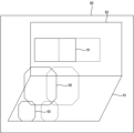
次に、情報処理装置50は、第2仮想投影装置と第2仮想投影面を、物理空間画像80に重畳して表示する(ステップS211)。例えば、情報処理装置50は、図25に示すように、物理空間画像80に第1仮想投影装置151、第1仮想投影面91、第2仮想投影装置251、及び第2仮想投影面252を重畳した画像を表示する。第2仮想投影装置251は、ステップS206によって第2仮想投影装置の機種として指定を受け付けた機種の3次元モデルである。
Next, the
第2仮想投影装置251は、第2仮想投影装置251の投影レンズの前玉がステップS207によって設定した第2仮想投影装置の位置となるように配置される。第2仮想投影面252は、第2仮想投影面252の中心位置が、ステップS208によって計算された第2仮想投影面の中心位置に対して、ステップS210によって設定されたレンズシフト量に基づいてシフトさせた位置となるように配置される。また、第2仮想投影面252のサイズは、ステップS209によって計算されたサイズである。
The second
これにより、ユーザは、機種を変更しても仮想投影装置や仮想投影面の位置を再設定することなく、投影状態を視覚的に把握でき、適切な機種の選定が容易になる。 As a result, even if the user changes the model, the user can visually grasp the projection state without resetting the position of the virtual projection device or the virtual projection surface, and it becomes easy to select the appropriate model.
情報処理装置50は、第1仮想投影装置151や第2仮想投影装置251のパラメータ変更によって、第1仮想投影面91や第2仮想投影面252の位置及びサイズが調整できる範囲を表示してもよい。例えば、情報処理装置50は、図26に示すように、第1仮想投影面91のサイズが第2仮想投影面252のサイズに最も近くなるときの、第2仮想投影装置251のレンズシフト範囲261を表示している。レンズシフト範囲261は、ステップS208によって計算された第2仮想投影面の中心位置を中心とする範囲である。
The
これにより、ユーザは、機種を変更した際の、仮想投影面の設定可能範囲を視覚的に把握でき、適切な機種の選定が容易になる。 This allows the user to visually grasp the settable range of the virtual projection plane when changing the model, making it easier to select an appropriate model.
次に、情報処理装置50は、第1仮想投影装置151の位置の変更指示をユーザから受け付けたか否かを判断する(ステップS212)。第1仮想投影装置151の位置の変更指示を受け付けた場合(ステップS212:Yes)は、情報処理装置50は、第1仮想投影装置151の位置を変更し、位置を変更した第1仮想投影装置151を物理空間画像80に重畳して表示する(ステップS213)。
Next, the
また、情報処理装置50は、現在の第1仮想投影装置151の位置と、ステップS142によって第1仮想投影装置の機種として指定を受け付けた機種で設定可能な投写比及びレンズシフト量と、に基づいて、第1仮想投影面91の位置及びサイズを再計算する。そして、情報処理装置50は、再計算した位置及びサイズの第1仮想投影面91を物理空間画像80に重畳して表示する(ステップS214)。
Further, the
次に、情報処理装置50は、第2仮想投影装置251の位置を、第1仮想投影装置151との距離が最小となるように再計算する。また、情報処理装置50は、第2仮想投影面252の位置及びサイズが、ステップS214によって再計算した第1仮想投影面91の位置及びサイズとの差が最小になるように第2仮想投影装置251のパラメータ(例えばレンズシフト量やズーム量)を再計算する。そして、情報処理装置50は、これらの再計算結果に基づく第2仮想投影装置251及び第2仮想投影面252を物理空間画像80に重畳して表示し(ステップS215)、ステップS212へ戻る。
Next, the
これにより、ユーザは、第1仮想投影装置151に対する位置変更以外の操作を行うことなく、比較対象とする機種(第2仮想投影装置251)の投影状態を視覚的に把握でき、適切な機種の選定が容易になる。
As a result, the user can visually grasp the projection state of the model to be compared (second virtual projection device 251) without performing any operation other than changing the position of the first
ステップS212において、第1仮想投影装置151の位置の変更指示を受け付けていない場合(ステップS212:No)は、情報処理装置50は、第1仮想投影装置151のズーム量の変更指示をユーザから受け付けたか否かを判断する(ステップS216)。第1仮想投影装置151のズーム量の変更指示を受け付けた場合(ステップS212:Yes)は、情報処理装置50は、変更後の第1仮想投影装置151のズーム量すなわち投写比に基づいて第1仮想投影面91のサイズを再計算し、再計算したサイズの第1仮想投影面91を物理空間画像80に重畳して表示する(ステップS217)。
In step S212, if the instruction to change the position of the first
次に、情報処理装置50は、第2仮想投影面252のサイズが、ステップS217によって再計算した第1仮想投影面91のサイズとの差が最小になるように第2仮想投影装置251のパラメータ(例えばズーム量)を再計算する。そして、情報処理装置50は、この再計算結果に基づく第2仮想投影装置251及び第2仮想投影面252を物理空間画像80に重畳して表示し(ステップS218)、ステップS212へ戻る。
Next, the
これにより、ユーザは、第1仮想投影装置151に対するズーム量(投写比)の変更以外の操作を行うことなく、比較対象とする機種(第2仮想投影装置251)の投影状態を視覚的に把握でき、適切な機種の選定が容易になる。
As a result, the user can visually grasp the projection state of the model to be compared (the second virtual projection device 251) without performing any operation other than changing the zoom amount (projection ratio) on the first
ステップS216において、第1仮想投影装置151の位置の変更指示を受け付けていない場合(ステップS216:No)は、情報処理装置50は、第1仮想投影装置151のレンズシフト量(第1仮想投影面91の位置)の変更指示をユーザから受け付けたか否かを判断する(ステップS219)。第1仮想投影装置151のレンズシフト量の変更指示を受け付けた場合(ステップS219:Yes)は、情報処理装置50は、変更後の第1仮想投影装置151のレンズシフト量に基づいて第1仮想投影面91の位置を再計算し、再計算した位置の第1仮想投影面91を物理空間画像80に重畳して表示する(ステップS220)。
In step S216, if the instruction to change the position of the first
次に、情報処理装置50は、ステップS206によって第2仮想投影装置の機種として指定を受け付けた機種の仕様に基づいて、第1仮想投影面91の中心位置と第2仮想投影面252の中心位置との間の距離が最小となるように、第2仮想投影装置251のレンズシフト量を設定する。また、情報処理装置50は、設定した第2仮想投影装置251のレンズシフト量に基づいて第2仮想投影面252の位置を再計算する。そして、情報処理装置50は、再計算した位置の第2仮想投影面252を物理空間画像80に重畳して表示し(ステップS221)、ステップS212へ戻る。
Next, the
これにより、ユーザは、第1仮想投影装置151のレンズシフト量(第1仮想投影面91の位置)の変更以外の操作を行うことなく、比較対象とする機種(第2仮想投影装置251)の投影状態を視覚的に把握でき、適切な機種の選定が容易になる。
As a result, the user can change the model (second virtual projection device 251) to be compared without performing any operation other than changing the lens shift amount (position of the first virtual projection surface 91) of the first
ステップS219において、第1仮想投影装置151のレンズシフト量の変更指示を受け付けていない場合(ステップS219:No)は、情報処理装置50は、ステップS212へ戻る。
In step S219, if the instruction to change the lens shift amount of the first
このように、プロジェクタ優先第2モードにおいて、情報処理装置50は、第1仮想投影面91と、第1仮想投影装置151と、第2仮想投影装置251と、第2仮想投影装置251に対応する第2仮想投影面252と、を含む第2画像を表示する。また、情報処理装置50は、第1仮想投影装置151の位置と、第1仮想投影面91の位置と、に基づいて、第2仮想投影面252の位置と、第2仮想投影装置251の位置と、を設定する。
In this manner, in the second projector priority mode, the
また、プロジェクタ優先第2モードにおいて、情報処理装置50は、第1仮想投影装置151の位置と、第1仮想投影面91の位置と、に基づいて第1仮想投影面91のサイズを設定し、第1仮想投影装置151の位置に基づいて、第2仮想投影装置の位置を設定(例えばなるべく近い位置に設定)する。そして、情報処理装置50は、第1仮想投影面91の位置及びサイズに基づいて、第2仮想投影面252の位置及びサイズに関する第2仮想投影装置251のパラメータ(レンズシフト量やズーム量など)を設定(例えば第1仮想投影面91と第2仮想投影面252の位置及びサイズがなるべく近くなるように設定)する。
Further, in the second projector priority mode, the
また、情報処理装置50は、第1仮想投影装置151又は第2仮想投影装置251のパラメータ変更により第1仮想投影面91又は第2仮想投影面252の位置及びサイズの少なくともいずれかが調整できる範囲を示す画像(例えばレンズシフト範囲261)を第2画像に含める処理を行ってもよい。
Further, the
(プロジェクタ優先第3モード)
図27は、プロジェクタ優先第3モードにおける情報処理装置50の処理の一例を示すフローチャートである。スクリーン優先モードの場合と同様に、情報処理装置50は、図27に示す処理の開始時に、図8に示した物理空間画像80を表示している。また、情報処理装置50は、物理空間画像80が示す物理空間を3次元的に認識している。
(Projector priority 3rd mode)
FIG. 27 is a flowchart illustrating an example of the processing of the
図27に示すステップS271~S276は、図20に示したステップS201~S206と同様である。ステップS276の次に、情報処理装置50は、ステップS276によって第2仮想投影装置の機種として指定を受け付けた機種の仕様に基づいて、第2仮想投影装置251の位置と、第2仮想投影面252の位置及びサイズと、を計算する(ステップS277)。ステップS277における計算については図28,図30において後述する。
Steps S271 to S276 shown in FIG. 27 are similar to steps S201 to S206 shown in FIG. 20. Next to step S276, the
次に、情報処理装置50は、第2仮想投影装置251及び第2仮想投影面252を、物理空間画像80に重畳して表示し(ステップS278)、一連の処理を終了する。ステップS278の後に、情報処理装置50は、図21に示したステップS212~S221と同様に、各種の変更指示に基づく処理を行ってもよい。
Next, the
図28は、図27のステップS277における計算の一例を示すフローチャートである。図29は、図28の例における図27の処理において情報処理装置50が表示する画像の一例である。図27のステップS277において、情報処理装置50は、例えば図28に示す処理を実行する。
FIG. 28 is a flowchart showing an example of the calculation in step S277 of FIG. 27. FIG. 29 is an example of an image displayed by the
まず、情報処理装置50は、第1仮想投影装置151及び第2仮想投影装置251が、互いに同じアスペクト比を設定可能か否かを判断する(ステップS281)。ステップS281の判断は、例えば図27のステップS272,S276によって指定された第1仮想投影装置151及び第2仮想投影装置251の各機種に基づいて行われる。
First, the
ステップS281において、第1仮想投影装置151及び第2仮想投影装置251が互いに同じアスペクト比を設定可能である場合(ステップS281:Yes)は、情報処理装置50は、第2仮想投影面252のサイズを、図27のステップS274によって計算した第1仮想投影面91のサイズと同じサイズに設定する(ステップS282)。
In step S281, if the first
ステップS281において、第1仮想投影装置151及び第2仮想投影装置251が互いに同じアスペクト比を設定可能でない場合(ステップS281:No)は、情報処理装置50は、第2仮想投影面252の上下幅が第1仮想投影装置151の上下幅以上であり、かつ第2仮想投影面252の左右幅が第1仮想投影装置151の上下幅以上である第2仮想投影面252のサイズを設定する(ステップS283)。
In step S281, if it is not possible to set the same aspect ratio for the first
次に、情報処理装置50は、ステップS206によって第2仮想投影装置の機種として指定を受け付けた機種の投写比に基づいて、第2仮想投影装置251の投影距離の取り得る範囲を計算する(ステップS284)。また、情報処理装置50は、第2仮想投影面252の位置を、第1仮想投影面91の位置と同じ位置に設定する(ステップS285)。
Next, the
次に、情報処理装置50は、第2仮想投影装置251の位置を設定し(ステップS286)、図27のステップS277を終了する。具体的には、情報処理装置50は、ステップS286において、ステップS285によって設定した第2仮想投影面252の位置と、ステップS284によって計算した第2仮想投影装置251の投影距離の取り得る範囲と、から求まる第2仮想投影装置251の設置候補範囲の中から、第1仮想投影装置151と第2仮想投影装置251との距離が最小となるように第2仮想投影装置251の位置を設定する。
Next, the
図28の例では、図27のステップS278において、例えば、情報処理装置50は、図29に示すように、中心位置が一致した第1仮想投影面91及び第2仮想投影面252と、これらに対応する第1仮想投影装置151及び第2仮想投影面252と、を表示している。図29の例では、第1仮想投影装置151との底面と第2仮想投影装置251の底面が同一平面上にない状態となっている。
In the example of FIG. 28, in step S278 of FIG. 27, the
図30は、図27のステップS277における計算の他の一例を示すフローチャートである。図31及び図32は、図30の例における図27の処理において情報処理装置50が表示する画像の一例である。第2仮想投影装置251の位置に関する制約条件を設定する場合、図27のステップS277において、情報処理装置50は、例えば図30に示す処理を実行する。
FIG. 30 is a flowchart showing another example of the calculation in step S277 of FIG. 27. 31 and 32 are examples of images displayed by the
図30に示すステップS301~S305は、図28に示したステップS281~S285と同様である。ステップS305の次に、情報処理装置50は、第2仮想投影装置251の設置可能範囲内に制約条件を満たす位置があるか否かを判断する(ステップS306)。第2仮想投影装置251の設置可能範囲内に制約条件を満たす位置がある場合(ステップS306:Yes)は、情報処理装置50は、第2仮想投影装置251の設置可能範囲かつ制約条件を満たす、第2仮想投影装置251の位置を設定し(ステップS307)、図27のステップS277を終了する。
Steps S301 to S305 shown in FIG. 30 are similar to steps S281 to S285 shown in FIG. 28. After step S305, the
ステップS306において、第2仮想投影装置251の設置可能範囲内に制約条件を満たす位置がない場合(ステップS306:No)は、情報処理装置50は、制約条件を満たし、かつステップS304によって計算した投影距離の範囲内となるように、第2仮想投影装置251の位置を変更する(ステップS308)。
In step S306, if there is no position that satisfies the constraint within the installable range of the second virtual projection device 251 (step S306: No), the
次に、情報処理装置50は、第2仮想投影面252の位置(中心位置)を、第1仮想投影面91の位置に最も近い位置(中心位置)に設定し(ステップS309)、図27のステップS277を終了する。
Next, the
例えば、図30の例で、第1仮想投影装置151との底面と第2仮想投影装置251の底面が同一平面上にあることを制約条件として設定するとする。また、第2仮想投影装置251では、第2仮想投影面252の位置(中心位置)と第1仮想投影面91の位置(中心位置)を同じ位置に設定すると、第2仮想投影装置251の設置可能範囲内にこの制約条件を満たす位置が存在しないものとする。この場合、図27のステップS278において、情報処理装置50は、例えば、図31に示すように、第1仮想投影装置151と、第1仮想投影装置151との底面と同一平面上にある底面を有する第2仮想投影装置251と、第1仮想投影面91と、第2仮想投影装置251から投影可能であり第1仮想投影面91に近い第2仮想投影面252と、を表示している。
For example, in the example of FIG. 30, it is assumed that the constraint is set that the bottom surface of the first
また、図30の例で、第2仮想投影装置251の底面が物理平面上にあることを制約条件として設定するとする。また、第1仮想投影装置151の位置を、第1仮想投影装置151の底面が床81(物理平面)とは異なる平面となる位置に設定したものとする。また、第2仮想投影装置251のレンズシフト範囲が十分に大きく、第2仮想投影面252の位置(中心位置)と第1仮想投影面91の位置(中心位置)を同じ位置に設定すると、第2仮想投影装置251の設置可能範囲は床81に重なるものとする。この場合、図27のステップS278において、情報処理装置50は、例えば、図32に示すように、第1仮想投影装置151と、底面が床81にある第2仮想投影装置251と、位置が一致した第1仮想投影面91及び第2仮想投影面252と、を表示している。
Furthermore, in the example of FIG. 30, it is assumed that the constraint is set that the bottom surface of the second
これにより、ユーザは、仮想投影装置の異なる機種で可能な限りサイズの近い仮想投影面を配置したときの仮想投影装置の位置の差異を視覚的に把握でき、適切な機種の選定が容易になる。 This allows the user to visually understand the difference in the position of the virtual projection device when arranging virtual projection surfaces that are as close in size as possible for different models of virtual projection devices, making it easier to select the appropriate model. .
このように、プロジェクタ優先第3モードにおいて、情報処理装置50は、プロジェクタ優先第2モードと同様に、第1仮想投影面91と、第1仮想投影装置151と、第2仮想投影装置251と、第2仮想投影装置251に対応する第2仮想投影面252と、を含む第2画像を表示する。また、情報処理装置50は、第1仮想投影装置151の位置と、第1仮想投影面91の位置と、に基づいて、第2仮想投影面252の位置と、第2仮想投影装置251の位置と、を設定する。
In this manner, in the third projector priority mode, the
また、プロジェクタ優先第3モードにおいて、情報処理装置50は、第1仮想投影装置151の位置と、第1仮想投影面91の位置と、に基づいて第1仮想投影面91のサイズを設定し、第1仮想投影面91の位置及びサイズに基づいて、第2仮想投影面252の位置及びサイズを設定(例えばなるべく近い位置及びサイズに設定)する。そして、情報処理装置50は、第1仮想投影装置151の位置に基づいて、第2仮想投影面252の位置を設定(例えば第1仮想投影面と第2仮想投影面の位置がなるべく近くなるように設定)する。
Further, in the third projector priority mode, the
また、プロジェクタ優先第3モードにおいて、第1仮想投影装置151及び第1仮想投影面91のそれぞれの位置やサイズが決定された後、これらの位置を制約として第2仮想投影装置251や第2仮想投影面252の設定が行われるが、情報処理装置50は、ユーザからの指示等の所定条件に応じてこの制約を解除してもよい。情報処理装置50は、この制約を解除した場合は、第2仮想投影装置251や第2仮想投影面252の位置やサイズを、ユーザからの指示に応じて、第1仮想投影装置151及び第1仮想投影面91の位置やサイズとは無関係に設定する。すなわち、情報処理装置50は、第1仮想投影装置151及び第1仮想投影面91の設定に基づく制約により第2仮想投影装置251及び第2仮想投影面252の設定を行う状態と、その制約によらずに第2仮想投影装置251及び第2仮想投影面252の設定を行う状態と、を切り替え可能であってもよい。
In the third projector priority mode, after the respective positions and sizes of the first
以上説明したように、情報処理装置50は、第1仮想投影面91と、第1仮想投影装置151又は第1設置可能範囲92と、第2仮想投影装置251又は第2設置可能範囲93と、が物理空間画像80に表示される第2画像を表示することで、設置する投影装置の機種選択に関するユーザの利便性を向上させることができる。
As described above, the
(機種検索モード)
図33は、機種検索モードにおける情報処理装置50の処理の一例を示すフローチャートである。図34~図38は、図33に示す処理において情報処理装置50が表示する画像の一例である。図7等の処理と同様に、情報処理装置50は、図33に示す処理の開始時に、図8に示した物理空間画像80を表示している。また、情報処理装置50は、物理空間画像80が示す物理空間を3次元的に認識している。
(Model search mode)
FIG. 33 is a flowchart illustrating an example of the processing of the
まず、情報処理装置50は、仮想投影面の位置及びサイズの指定をユーザから受け付ける(ステップS331)。次に、情報処理装置50は、ステップS331によって受け付けた指定に基づいて、仮想投影面を物理空間画像80に重畳して表示する(ステップS332)。物理空間画像80に仮想投影面を重畳した画像を表示する処理は、例えば図9に示した物理空間画像80に仮想投影面を重畳した画像を表示する処理と同様である。例えば、情報処理装置50は、図34に示すように、物理空間画像80に仮想投影面341を重畳した画像を表示する。
First, the
次に、情報処理装置50は、仮想投影装置の設置を希望する範囲である設置候補範囲の位置及びサイズの指定をユーザから受け付ける(ステップS333)。次に、情報処理装置50は、ステップS333によって指定を受け付けた設置候補範囲を物理空間画像80に重畳して表示する(ステップS334)。例えば、情報処理装置50は、図35に示すように、物理空間画像80に仮想投影面341及び設置候補範囲351を重畳した画像を表示する。この例では、設置候補範囲351は直方体となっている。
Next, the
次に、情報処理装置50は、登録されている投影装置の機種の中から、ステップS331によって指定を受け付けた位置及びサイズの仮想投影面341を実現可能な機種を抽出する(ステップS335)。例えば、情報処理装置50は、登録されている投影装置の機種のそれぞれについて、その機種をステップS333によって指定を受け付けた設置候補範囲351内に配置してその機種のパラメータ(例えばレンジシフト量やズーム量)の設定により仮想投影面341を実現可能か否かを判定することにより、ステップS335の抽出を行う。
Next, the
次に、情報処理装置50は、ステップS335によって抽出した機種の一覧を表示する(ステップS336)。例えば、情報処理装置50は、図36に示す適合機種一覧361を表示する。この例では、適合機種一覧361は、仮想投影面341を実現可能な機種(適合する機種)として、「プロジェクタ1」、「プロジェクタ2」、及び「プロジェクタ5」を示している。なお、情報処理装置50は、図34に示した画像に代えて適合機種一覧361を表示してもよいし、図34に示した画像と同時に適合機種一覧361を表示してもよい。
Next, the
これにより、ユーザは、投影装置を設置したい設置候補範囲351に対して適合する機種を絞り込むことができ、適切な機種の選定が容易になる。
Thereby, the user can narrow down the models that are suitable for the
次に、情報処理装置50は、ステップS336によって表示した一覧の中から、仮想投影装置の機種の選択をユーザから受け付ける(ステップS337)。
Next, the
次に、情報処理装置50は、ステップS331によって指定を受け付けた仮想投影面341の位置及びサイズと、ステップS337によって仮想投影装置の機種として指定を受け付けた機種で設定可能な投写比とレンズシフト量に基づいて、設置可能範囲の位置及びサイズを計算する。そして、情報処理装置50は、位置及びサイズを計算した設置可能範囲を物理空間画像80に重畳して表示する(ステップS338)。例えば、情報処理装置50は、図37に示すように、物理空間画像80に仮想投影面341、設置候補範囲351、及び設置可能範囲371を重畳した画像を表示する。この例では、設置候補範囲351は直方体となっている。なお、このとき、情報処理装置50は、設置可能範囲371を、ユーザが指定した設置候補範囲351との重複領域のみに限定して表示してもよい。
Next, the
これにより、ユーザは、設置を検討している機種によって限定される設置可能範囲を視覚的に把握でき、適切な機種の選定が容易になる。 This allows the user to visually grasp the installation range that is limited by the model the user is considering installing, making it easier to select the appropriate model.
また、図33のステップS335において、情報処理装置50は、登録されている投影装置の機種のそれぞれについて、その機種をステップS333によって指定を受け付けた設置候補範囲351内に配置してその機種のパラメータの設定により仮想投影面341を実現可能か否かを、クロップの有無毎に判定してもよい。そして、ステップS336において、情報処理装置50は、仮想投影面341を実現可能な機種の候補を、クロップ無しで仮想投影面341を実現可能な機種の候補と、クロップ有りで仮想投影面341を実現可能な機種の候補と、を区別して表示してもよい。例えば、情報処理装置50は、図38に示す適合機種一覧361を表示する。この例では、適合機種一覧361は、仮想投影面341を実現可能な機種(適合する機種)として、「プロジェクタ1」、「プロジェクタ2」、「プロジェクタ5」、及び「プロジェクタ6」を示している。これらのうち、「プロジェクタ1」、「プロジェクタ2」、及び「プロジェクタ5」はクロップ無しで仮想投影面341を実現可能な機種であり、「プロジェクタ6」はクロップ有りで仮想投影面341を実現可能な機種であったとする。この場合、適合機種一覧361において、「プロジェクタ6」には、クロップ有りで仮想投影面341を実現可能な機種であることを示すクロップマーク381が付される。
In addition, in step S335 of FIG. 33, the
これにより、ユーザは、投影装置を設置したい範囲に対して適合する機種のうち、調整の必要な機種とそうでない機種を把握することができ、適切な機種の選定が容易になる。 This allows the user to understand which models require adjustment and which do not, among the models that are suitable for the range in which the projection device is desired to be installed, making it easier to select an appropriate model.
このように、機種検索モードにおいて、情報処理装置50は、センサ65の撮像装置により撮像された物理空間画像80(第3画像)に基づいてユーザから受け付けた、仮想投影面341(投影面)の位置及びサイズ(範囲)と、投影装置の設置候補範囲351と、の指定に基づいて、投影装置の設置候補範囲351への設置により仮想投影面341の範囲への投影が可能な投影装置の機種の候補である適合機種一覧361を出力する。
In this way, in the model search mode, the
また、機種検索モードにおいて、情報処理装置50は、投影装置の設置可能範囲371を、投影装置の設置候補範囲351との重複領域に限定して物理空間画像80に表示してもよい。また、機種検索モードにおいて、情報処理装置50は、適合機種一覧361を、投影装置候補の使用条件(例えばクロップの要否)とともに出力してもよい。
Furthermore, in the model search mode, the
また、情報処理装置50は、機種検索モードの処理を、上記のスクリーン優先モード、プロジェクタ優先第1モード、プロジェクタ優先第2モード、又はプロジェクタ優先第3モードの処理と組み合わせて実行してもよい。例えば、情報処理装置50は、上記のスクリーン優先モード、プロジェクタ優先第1モード、プロジェクタ優先第2モード、又はプロジェクタ優先第3モードにおいて、第1仮想投影装置及び第2仮想投影装置の機種の指定を受け付ける処理に代えて、機種検索モードにおいて出力した候補の中から投影装置の機種の指定を受け付ける処理を実行してもよい。
Furthermore, the
以上説明したように、情報処理装置50は、物理空間画像80(第3画像)に基づいてユーザから受け付けた、仮想投影面341(投影面)の位置及びサイズ(範囲)と、投影装置の設置候補範囲351と、の指定に基づいて、投影装置の設置候補範囲351への設置により仮想投影面341の範囲への投影が可能な投影装置の機種の候補である適合機種一覧361を出力することで、設置する投影装置の機種選択に関するユーザの利便性を向上させることができる。
As explained above, the
(変形例)
上記の各実施形態に関する変形例について説明する。
(Modified example)
Modifications of each of the above embodiments will be described.
<変形例1>
物理空間を示す物理空間画像80が、情報処理装置50が備える撮像装置による撮像で得られた画像をリアルタイムに示すスルー画像である場合について説明したが、物理空間画像80はこれに限らない。例えば、物理空間画像80は、過去に物理空間を撮像して得られた静止画像であってもよい。また、物理空間画像80は、撮像して得られた画像ではなくてもよく、例えば、物理空間の構造を示す3次元データに基づいて生成された画像であってもよい。
<
Although a case has been described in which the
<変形例2>
情報処理装置50がタッチパネル51を有するタブレット端末である場合について説明したが、情報処理装置50はこのような構成に限らない。例えば、情報処理装置50は、スマートフォンやパーソナルコンピュータなどの情報端末であってもよい。
<
Although the case where the
<変形例3>
情報処理装置50が第2画像を表示する構成について説明したが、情報処理装置50は、生成した第2画像を他の装置へ送信することにより、その他の装置に第2画像を表示させる制御を行ってもよい。この場合に、情報処理装置50は、表示装置を備えないサーバ装置などであってもよい。
<Modification 3>
Although the configuration in which the
<変形例4>
物理空間画像80が情報処理装置50の撮像装置による撮像で得られた画像である場合について説明したが、物理空間画像80は情報処理装置50とは装置による撮像で得らえられた画像をその装置から情報処理装置50が受信したものであってもよい。この場合、情報処理装置50は撮像装置を備えない装置であってもよい。
<
Although the
<変形例5>
プロジェクタ優先第2モード及びプロジェクタ優先第3モードにおいて、情報処理装置50は、第2画像を表示した後に、第1仮想投影装置151の設置状態(例えば床置きか天吊りか等)又は第2仮想投影装置251の位置がユーザ指定により変更された場合、第2仮想投影装置251の設置状態、第2仮想投影装置251のパラメータ(例えばレンズシフト量やズーム量)、及び第2仮想投影面252の位置の少なくともいずれかを再設定してもよい。
<Modification 5>
In the second projector priority mode and the third projector priority mode, after displaying the second image, the
<変形例6>
情報処理装置50は、第2画像を表示する際に、第2画像に重畳する各オブジェクト(第1仮想投影面91と、第1仮想投影装置151又は第1設置可能範囲92と、第2仮想投影装置251又は第2設置可能範囲93)のうち一部のオブジェクトの視認性を他のオブジェクトの視認性より低くする制御を行ってもよい。例えば、情報処理装置50は、図17に示した第2画像に含まれる第1仮想投影面91、第1仮想投影装置151、及び第2設置可能範囲93のうち、第1仮想投影装置151の不透明度を、第1仮想投影面91及び第2設置可能範囲93の不透明度より高く設定することにより、第1仮想投影装置151の視認性を低下させる制御を行う。各オブジェクトのうち視認性を低下させるオブジェクトは、例えばユーザ操作によって選択されてもよいし、情報処理装置50が取得可能か各種の情報(例えば投影装置のパラメータ、情報処理装置50の撮像装置の位置、操作の順序など)に基づいて自動的に選択されてもよい。
<
When displaying the second image, the
<変形例7>
第2画像が、第1仮想投影面91と、第1仮想投影装置151又は第1設置可能範囲92と、第2仮想投影装置251又は第2設置可能範囲93と、を含む静止画である場合について説明したが、第2画像は、第1仮想投影面91と、第1仮想投影装置151又は第1設置可能範囲92と、第2仮想投影装置251又は第2設置可能範囲93と、が交互に表示される動画像であってもよい。
<Modification 7>
When the second image is a still image including the first
なお、前述した実施形態で説明した情報処理方法は、予め用意された情報処理プログラムをコンピュータで実行することにより実現できる。本情報処理プログラムは、コンピュータが読み取り可能な記憶媒体に記録され、記憶媒体から読み出されることによって実行される。また、本情報処理プログラムは、フラッシュメモリ等の非一過性の記憶媒体に記憶された形で提供されてもよいし、インターネット等のネットワークを介して提供されてもよい。本情報処理プログラムを実行するコンピュータは、情報処理装置に含まれるものであってもよいし、情報処理装置と通信可能なスマートフォン、タブレット端末、又はパーソナルコンピュータ等の電子機器に含まれるものでもあってもよいし、これら情報処理装置及び電子機器と通信可能なサーバ装置に含まれるものであってもよい。 Note that the information processing method described in the above-described embodiment can be realized by executing a previously prepared information processing program on a computer. This information processing program is recorded on a computer-readable storage medium, and is executed by being read from the storage medium. Further, the information processing program may be provided in a form stored in a non-transitory storage medium such as a flash memory, or may be provided via a network such as the Internet. The computer that executes this information processing program may be included in an information processing device, or may be included in an electronic device such as a smartphone, tablet terminal, or personal computer that can communicate with the information processing device. Alternatively, it may be included in a server device that can communicate with these information processing devices and electronic devices.
上記の各実施形態及び各変形例は、組み合わせて実施することができる。 The above embodiments and modifications can be implemented in combination.
本明細書には少なくとも以下の事項が記載されている。 This specification describes at least the following matters.
(1)
プロセッサを備える情報処理装置であって、
上記プロセッサは、
撮像装置により撮像された第1画像を表す第1画像データと、
第1仮想投影面に関する第1仮想投影面データ、上記第1仮想投影面に対応する第1仮想投影装置に関する第1仮想投影装置データ、及び第2仮想投影装置に関する第2仮想投影装置データと、を取得し、
上記第1仮想投影面データ、上記第1仮想投影装置データ、及び上記第2仮想投影装置データに基づいて、上記第1仮想投影面と、上記第1仮想投影装置又は上記第1仮想投影装置の設置可能範囲と、上記第2仮想投影装置又は上記第2仮想投影装置の設置可能範囲と、が上記第1画像に表示される第2画像を表す第2画像データを生成し、
上記第2画像データを出力先に出力する、
情報処理装置。
(1)
An information processing device comprising a processor,
The above processor is
First image data representing a first image captured by the imaging device;
First virtual projection plane data regarding a first virtual projection plane, first virtual projection device data regarding a first virtual projection device corresponding to the first virtual projection surface, and second virtual projection device data regarding a second virtual projection device; get
Based on the first virtual projection plane data, the first virtual projection device data, and the second virtual projection device data, the first virtual projection plane, the first virtual projection device, or the first virtual projection device generating second image data representing a second image displayed in the first image, the installable range and the second virtual projection device or the installable range of the second virtual projection device;
outputting the second image data to an output destination;
Information processing device.
(2)
(1)に記載の情報処理装置であって、
上記第2画像は、上記第1仮想投影面と、上記第1仮想投影装置の設置可能範囲と、上記第2仮想投影装置の設置可能範囲と、を含み、
上記プロセッサは、
上記第1仮想投影面の位置及びサイズの少なくともいずれかに基づいて、上記第1仮想投影装置の設置可能範囲及び上記第2仮想投影装置の設置可能範囲を設定する、
情報処理装置。
(2)
The information processing device according to (1),
The second image includes the first virtual projection plane, an installable range of the first virtual projection device, and an installable range of the second virtual projection device,
The above processor is
setting an installable range of the first virtual projection device and an installable range of the second virtual projection device based on at least one of the position and size of the first virtual projection plane;
Information processing device.
(3)
(2)に記載の情報処理装置であって、
上記プロセッサは、
上記第1仮想投影面の位置及びサイズの少なくともいずれかが変更された場合、上記第1仮想投影装置の設置可能範囲及び上記第2仮想投影装置の設置可能範囲を再設定する、
情報処理装置。
(3)
The information processing device according to (2),
The above processor is
resetting the installable range of the first virtual projection device and the installable range of the second virtual projection device when at least one of the position and size of the first virtual projection plane is changed;
Information processing device.
(4)
(1)に記載の情報処理装置であって、
上記第2画像は、上記第1仮想投影面と、上記第1仮想投影装置と、上記第2仮想投影装置の設置可能範囲と、を含み、
上記プロセッサは、
上記第1仮想投影装置の位置に基づいて、上記第1仮想投影面の位置及びサイズの少なくともいずれかを設定し、
上記第1仮想投影面の位置及びサイズの少なくともいずれかに基づいて、上記第2仮想投影装置の設置可能範囲を設定する、
情報処理装置。
(4)
The information processing device according to (1),
The second image includes the first virtual projection plane, the first virtual projection device, and an installation range of the second virtual projection device,
The above processor is
setting at least one of the position and size of the first virtual projection plane based on the position of the first virtual projection device;
setting an installable range of the second virtual projection device based on at least one of the position and size of the first virtual projection plane;
Information processing device.
(5)
(4)に記載の情報処理装置であって、
上記プロセッサは、
上記第1仮想投影装置の位置又はパラメータが変更された場合、上記第1仮想投影面の位置及びサイズの少なくともいずれかと、上記第2仮想投影装置の設置可能範囲と、を再設定する、
情報処理装置。
(5)
The information processing device according to (4),
The above processor is
When the position or parameters of the first virtual projection device are changed, resetting at least one of the position and size of the first virtual projection plane and the installable range of the second virtual projection device;
Information processing device.
(6)
(4)又は(5)に記載の情報処理装置であって、
上記プロセッサは、
上記第1仮想投影面の位置が変更された場合、上記第2仮想投影装置の設置可能範囲を再設定する、
情報処理装置。
(6)
The information processing device according to (4) or (5),
The above processor is
resetting the installable range of the second virtual projection device when the position of the first virtual projection plane is changed;
Information processing device.
(7)
(1)に記載の情報処理装置であって、
上記第2画像は、上記第1仮想投影面と、上記第1仮想投影装置と、上記第2仮想投影装置と、上記第2仮想投影装置に対応する第2仮想投影面と、を含み、
上記プロセッサは、
上記第1仮想投影装置の位置と、上記第1仮想投影面の位置と、に基づいて、上記第2仮想投影面の位置と、上記第2仮想投影装置の位置と、を設定する、
情報処理装置。
(7)
The information processing device according to (1),
The second image includes the first virtual projection plane, the first virtual projection device, the second virtual projection device, and a second virtual projection plane corresponding to the second virtual projection device,
The above processor is
setting the position of the second virtual projection plane and the position of the second virtual projection apparatus based on the position of the first virtual projection apparatus and the position of the first virtual projection plane;
Information processing device.
(8)
(7)に記載の情報処理装置であって、
上記プロセッサは、
上記第1仮想投影装置の位置と、上記第1仮想投影面の位置と、に基づいて上記第1仮想投影面のサイズを設定し、
上記第1仮想投影装置の位置に基づいて、上記第2仮想投影装置の位置を設定し、
上記第1仮想投影面の位置及びサイズに基づいて、上記第2仮想投影面の位置及びサイズに関する上記第2仮想投影面のパラメータを設定する、
情報処理装置。
(8)
The information processing device according to (7),
The above processor is
setting the size of the first virtual projection plane based on the position of the first virtual projection device and the position of the first virtual projection plane;
setting the position of the second virtual projection device based on the position of the first virtual projection device;
setting parameters of the second virtual projection plane regarding the position and size of the second virtual projection plane based on the position and size of the first virtual projection plane;
Information processing device.
(9)
(7)に記載の情報処理装置であって、
上記プロセッサは、
上記第1仮想投影装置の位置と、上記第1仮想投影面の位置と、に基づいて上記第1仮想投影面のサイズを設定し、
上記第1仮想投影面の位置及びサイズに基づいて、上記第2仮想投影面の位置及びサイズを設定し、
上記第1仮想投影装置の位置に基づいて、上記第2仮想投影面の位置に関する上記第2仮想投影面のパラメータを設定する、
情報処理装置。
(9)
The information processing device according to (7),
The above processor is
setting the size of the first virtual projection plane based on the position of the first virtual projection device and the position of the first virtual projection plane;
setting the position and size of the second virtual projection plane based on the position and size of the first virtual projection plane;
setting parameters of the second virtual projection plane regarding the position of the second virtual projection plane based on the position of the first virtual projection device;
Information processing device.
(10)
(7)から(9)のいずれか1項に記載の情報処理装置であって、
上記プロセッサは、
上記第1仮想投影装置又は上記第2仮想投影装置のパラメータ変更により上記第1仮想投影面又は上記第2仮想投影面の位置及びサイズの少なくともいずれかが調整できる範囲を示す画像を上記第2画像に含める処理を行う、
情報処理装置。
(10)
The information processing device according to any one of (7) to (9),
The above processor is
The second image is an image indicating a range in which at least one of the position and size of the first virtual projection plane or the second virtual projection plane can be adjusted by changing the parameters of the first virtual projection device or the second virtual projection device. perform processing to include it in
Information processing device.
(11)
(7)から(10)のいずれか1項に記載の情報処理装置であって、
上記プロセッサは、
上記第1仮想投影装置の設置状態又は上記第2仮想投影装置の位置が変更された場合、上記第2仮想投影装置の設置状態、上記第2仮想投影装置のパラメータ、及び上記第2仮想投影面の位置の少なくともいずれかを再設定する、
情報処理装置。
(11)
The information processing device according to any one of (7) to (10),
The above processor is
When the installation state of the first virtual projection device or the position of the second virtual projection device is changed, the installation state of the second virtual projection device, the parameters of the second virtual projection device, and the second virtual projection plane resetting at least one of the positions of
Information processing device.
(12)
(7)から(11)のいずれか1項に記載の情報処理装置であって、
上記プロセッサは、
上記第1仮想投影装置及び上記第1仮想投影面の設定に基づく制約により上記第2仮想投影装置及び上記第2仮想投影面の設定を行う状態と、上記制約によらずに上記第2仮想投影装置及び上記第2仮想投影面の設定を行う状態と、を切り替え可能である、
情報処理装置。
(12)
The information processing device according to any one of (7) to (11),
The above processor is
a state in which the second virtual projection device and the second virtual projection surface are set according to constraints based on the settings of the first virtual projection device and the first virtual projection plane; and a state in which the second virtual projection device and the second virtual projection plane are set without the constraints; being able to switch between a state in which the device and the second virtual projection plane are set;
Information processing device.
(13)
(1)から(12)のいずれか1項に記載の情報処理装置であって、
上記プロセッサは、
上記撮像装置により撮像された第3画像に基づいてユーザから受け付けた、投影面の範囲と、投影装置の設置範囲と、の指定に基づいて、上記投影装置の設置範囲への設置により上記投影面の範囲への投影が可能な投影装置候補を出力し、
上記第1仮想投影装置及び上記第2仮想投影装置は、上記投影装置候補の中からユーザにより選択された各投影装置を示す仮想投影装置である、
情報処理装置。
(13)
The information processing device according to any one of (1) to (12),
The above processor is
Based on the designation of the range of the projection plane and the installation range of the projection device received from the user based on the third image captured by the imaging device, the projection device is installed in the installation range of the projection device. Output projector candidates that can project to the range of
The first virtual projection device and the second virtual projection device are virtual projection devices representing each projection device selected by the user from among the projection device candidates.
Information processing device.
(14)
(13)に記載の情報処理装置であって、
上記プロセッサは、
上記第1仮想投影装置及び上記第2仮想投影装置の少なくともいずれかの設置可能範囲を、上記投影装置の設置範囲との重複領域に限定して上記第1画像に表示する、
情報処理装置。
(14)
The information processing device according to (13),
The above processor is
displaying in the first image an installation range of at least one of the first virtual projection device and the second virtual projection device, limited to an overlapping area with the installation range of the projection device;
Information processing device.
(15)
(13)又は(14)に記載の情報処理装置であって、
上記プロセッサは、
上記投影装置候補を、上記投影装置候補の使用条件とともに出力する、
情報処理装置。
(15)
The information processing device according to (13) or (14),
The above processor is
outputting the projection device candidate together with usage conditions of the projection device candidate;
Information processing device.
(16)
(1)から(15)のいずれか1項に記載の情報処理装置であって、
上記プロセッサは、
上記第2画像において、上記第1仮想投影面と、上記第1仮想投影装置又は上記第1仮想投影装置の設置可能範囲と、上記第2仮想投影装置又は上記第2仮想投影装置の設置可能範囲と、のうち、一部のオブジェクトの視認性を他のオブジェクトの視認性より低くする制御を行う、
情報処理装置。
(16)
The information processing device according to any one of (1) to (15),
The above processor is
In the second image, the first virtual projection plane, the first virtual projection device or an installable range of the first virtual projection device, and the installable range of the second virtual projection device or the second virtual projection device Among these, controlling the visibility of some objects to be lower than that of other objects,
Information processing device.
(17)
情報処理装置のプロセッサが、
撮像装置により撮像された第1画像を表す第1画像データと、
第1仮想投影面に関する第1仮想投影面データ、上記第1仮想投影面に対応する第1仮想投影装置に関する第1仮想投影装置データ、及び第2仮想投影装置に関する第2仮想投影装置データと、を取得し、
上記第1仮想投影面データ、上記第1仮想投影装置データ、及び上記第2仮想投影装置データに基づいて、上記第1仮想投影面と、上記第1仮想投影装置又は上記第1仮想投影装置の設置可能範囲と、上記第2仮想投影装置又は上記第2仮想投影装置の設置可能範囲と、が上記第1画像に表示される第2画像を表す第2画像データを生成し、
上記第2画像データを出力先に出力する、
情報処理方法。
(17)
The processor of the information processing device
First image data representing a first image captured by the imaging device;
First virtual projection plane data regarding a first virtual projection plane, first virtual projection device data regarding a first virtual projection device corresponding to the first virtual projection surface, and second virtual projection device data regarding a second virtual projection device; get
Based on the first virtual projection plane data, the first virtual projection device data, and the second virtual projection device data, the first virtual projection plane, the first virtual projection device, or the first virtual projection device generating second image data representing a second image displayed in the first image, the installable range and the second virtual projection device or the installable range of the second virtual projection device;
outputting the second image data to an output destination;
Information processing method.
(18)
情報処理装置のプロセッサに、
撮像装置により撮像された第1画像を表す第1画像データと、
第1仮想投影面に関する第1仮想投影面データ、上記第1仮想投影面に対応する第1仮想投影装置に関する第1仮想投影装置データ、及び第2仮想投影装置に関する第2仮想投影装置データと、を取得し、
上記第1仮想投影面データ、上記第1仮想投影装置データ、及び上記第2仮想投影装置データに基づいて、上記第1仮想投影面と、上記第1仮想投影装置又は上記第1仮想投影装置の設置可能範囲と、上記第2仮想投影装置又は上記第2仮想投影装置の設置可能範囲と、が上記第1画像に表示される第2画像を表す第2画像データを生成し、
上記第2画像データを出力先に出力する、
処理を実行させるための情報処理プログラム。
(18)
In the processor of the information processing device,
First image data representing a first image captured by the imaging device;
First virtual projection plane data regarding a first virtual projection plane, first virtual projection device data regarding a first virtual projection device corresponding to the first virtual projection surface, and second virtual projection device data regarding a second virtual projection device; get
Based on the first virtual projection plane data, the first virtual projection device data, and the second virtual projection device data, the first virtual projection plane, the first virtual projection device, or the first virtual projection device generating second image data representing a second image displayed in the first image, the installable range and the second virtual projection device or the installable range of the second virtual projection device;
outputting the second image data to an output destination;
An information processing program for executing processing.
(19)
プロセッサを備える情報処理装置であって、
上記プロセッサは、
撮像装置により撮像された画像に基づいてユーザから受け付けた、投影面の範囲と、投影装置の設置範囲と、の指定に基づいて、上記投影装置の設置範囲への設置により上記投影面の範囲への投影が可能な投影装置候補を出力する、
情報処理装置。
(19)
An information processing device comprising a processor,
The above processor is
Based on the designation of the range of the projection surface and the installation range of the projection device received from the user based on the image captured by the imaging device, the projection device is installed in the installation range to the range of the projection surface. Output projector candidates capable of projecting
Information processing device.
(20)
情報処理装置のプロセッサが、
撮像装置により撮像された画像に基づいてユーザから受け付けた、投影面の範囲と、投影装置の設置範囲と、の指定に基づいて、上記投影装置の設置範囲への設置により上記投影面の範囲への投影が可能な投影装置候補を出力する、
情報処理方法。
(20)
The processor of the information processing device
Based on the designation of the range of the projection surface and the installation range of the projection device received from the user based on the image captured by the imaging device, the projection device is installed in the installation range to the range of the projection surface. Output projector candidates capable of projecting
Information processing method.
(21)
情報処理装置のプロセッサに、
撮像装置により撮像された画像に基づいてユーザから受け付けた、投影面の範囲と、投影装置の設置範囲と、の指定に基づいて、上記投影装置の設置範囲への設置により上記投影面の範囲への投影が可能な投影装置候補を出力する、
処理を実行させるための情報処理プログラム。
(21)
In the processor of the information processing device,
Based on the designation of the range of the projection surface and the installation range of the projection device received from the user based on the image captured by the imaging device, the projection device is installed in the installation range to the range of the projection surface. Output projector candidates capable of projecting
An information processing program for executing processing.
以上、各種の実施の形態について説明したが、本発明はかかる例に限定されないことは言うまでもない。当業者であれば、特許請求の範囲に記載された範疇内において、各種の変更例又は修正例に想到し得ることは明らかであり、それらについても当然に本発明の技術的範囲に属するものと了解される。また、発明の趣旨を逸脱しない範囲において、上記実施の形態における各構成要素を任意に組み合わせてもよい。 Although various embodiments have been described above, it goes without saying that the present invention is not limited to such examples. It is clear that those skilled in the art can come up with various changes or modifications within the scope of the claims, and these naturally fall within the technical scope of the present invention. Understood. Further, each of the constituent elements in the above embodiments may be arbitrarily combined without departing from the spirit of the invention.
なお、本出願は、2022年3月25日出願の日本特許出願(特願2022-049515)に基づくものであり、その内容は本出願の中に参照として援用される。 Note that this application is based on a Japanese patent application (Japanese Patent Application No. 2022-049515) filed on March 25, 2022, the contents of which are incorporated into this application as a reference.
1 投影部
2 操作受付部
2A,3A 中空部
2a,2b,3a,3c,15a 開口
4 制御装置
4a,62 メモリ
6 被投影物
10 投影装置
11 投影範囲
12 光変調ユニット
15 筐体
21 光源
22 光変調部
23 投影光学系
24 制御回路
31 第2光学系
32,122 反射部材
33 第3光学系
34 レンズ
50 情報処理装置
51 タッチパネル
61 プロセッサ
63 通信インタフェース
64 ユーザインタフェース
65 センサ
69 バス
80 物理空間画像
81 床
82 壁
91 第1仮想投影面
92 第1設置可能範囲
93 第2設置可能範囲
101 本体部
102 第1部材
103 第2部材
104 投影方向変更機構
105 シフト機構
106 光学ユニット
121 第1光学系
151 第1仮想投影装置
251 第2仮想投影装置
252 第2仮想投影面
261 レンズシフト範囲
341 仮想投影面
351 設置候補範囲
361 適合機種一覧
371 設置可能範囲
381 クロップマーク
G1 画像
P1~P4 位置
D1~D3 投影距離
1
Claims (18)
前記プロセッサは、
撮像装置により撮像された第1画像を表す第1画像データと、
第1仮想投影面に関する第1仮想投影面データ、前記第1仮想投影面に対応する第1仮想投影装置に関する第1仮想投影装置データ、及び第2仮想投影装置に関する第2仮想投影装置データと、を取得し、
前記第1仮想投影面データ、前記第1仮想投影装置データ、及び前記第2仮想投影装置データに基づいて、前記第1仮想投影面と、前記第1仮想投影装置又は前記第1仮想投影装置の設置可能範囲と、前記第2仮想投影装置又は前記第2仮想投影装置の設置可能範囲と、が前記第1画像に表示される第2画像を表す第2画像データを生成し、
前記第2画像データを出力先に出力する、
情報処理装置。 An information processing device comprising a processor,
The processor includes:
First image data representing a first image captured by the imaging device;
First virtual projection surface data regarding a first virtual projection surface, first virtual projection device data regarding a first virtual projection device corresponding to the first virtual projection surface, and second virtual projection device data regarding a second virtual projection device; get
Based on the first virtual projection plane data, the first virtual projection device data, and the second virtual projection device data, the first virtual projection plane, the first virtual projection device, or the first virtual projection device generating second image data in which an installable range and an installable range of the second virtual projection device or the second virtual projection device represent a second image displayed in the first image;
outputting the second image data to an output destination;
Information processing device.
前記第2画像は、前記第1仮想投影面と、前記第1仮想投影装置の設置可能範囲と、前記第2仮想投影装置の設置可能範囲と、を含み、
前記プロセッサは、
前記第1仮想投影面の位置及びサイズの少なくともいずれかに基づいて、前記第1仮想投影装置の設置可能範囲及び前記第2仮想投影装置の設置可能範囲を設定する、
情報処理装置。 The information processing device according to claim 1,
The second image includes the first virtual projection plane, an installable range of the first virtual projection device, and an installable range of the second virtual projection device,
The processor includes:
setting an installable range of the first virtual projection device and an installable range of the second virtual projection device based on at least one of the position and size of the first virtual projection plane;
Information processing device.
前記プロセッサは、
前記第1仮想投影面の位置及びサイズの少なくともいずれかが変更された場合、前記第1仮想投影装置の設置可能範囲及び前記第2仮想投影装置の設置可能範囲を再設定する、
情報処理装置。 The information processing device according to claim 2,
The processor includes:
If at least one of the position and size of the first virtual projection plane is changed, resetting the installable range of the first virtual projection device and the installable range of the second virtual projection device;
Information processing device.
前記第2画像は、前記第1仮想投影面と、前記第1仮想投影装置と、前記第2仮想投影装置の設置可能範囲と、を含み、
前記プロセッサは、
前記第1仮想投影装置の位置に基づいて、前記第1仮想投影面の位置及びサイズの少なくともいずれかを設定し、
前記第1仮想投影面の位置及びサイズの少なくともいずれかに基づいて、前記第2仮想投影装置の設置可能範囲を設定する、
情報処理装置。 The information processing device according to claim 1,
The second image includes the first virtual projection plane, the first virtual projection device, and an installation range of the second virtual projection device,
The processor includes:
setting at least one of the position and size of the first virtual projection plane based on the position of the first virtual projection device;
setting an installable range of the second virtual projection device based on at least one of the position and size of the first virtual projection plane;
Information processing device.
前記プロセッサは、
前記第1仮想投影装置の位置又はパラメータが変更された場合、前記第1仮想投影面の位置及びサイズの少なくともいずれかと、前記第2仮想投影装置の設置可能範囲と、を再設定する、
情報処理装置。 The information processing device according to claim 4,
The processor includes:
When the position or parameters of the first virtual projection device are changed, resetting at least one of the position and size of the first virtual projection plane and the installable range of the second virtual projection device;
Information processing device.
前記プロセッサは、
前記第1仮想投影面の位置が変更された場合、前記第2仮想投影装置の設置可能範囲を再設定する、
情報処理装置。 The information processing device according to claim 4 or 5,
The processor includes:
resetting an installable range of the second virtual projection device when the position of the first virtual projection plane is changed;
Information processing device.
前記第2画像は、前記第1仮想投影面と、前記第1仮想投影装置と、前記第2仮想投影装置と、前記第2仮想投影装置に対応する第2仮想投影面と、を含み、
前記プロセッサは、
前記第1仮想投影装置の位置と、前記第1仮想投影面の位置と、に基づいて、前記第2仮想投影面の位置と、前記第2仮想投影装置の位置と、を設定する、
情報処理装置。 The information processing device according to claim 1,
The second image includes the first virtual projection plane, the first virtual projection device, the second virtual projection device, and a second virtual projection plane corresponding to the second virtual projection device,
The processor includes:
setting the position of the second virtual projection plane and the position of the second virtual projection apparatus based on the position of the first virtual projection apparatus and the position of the first virtual projection plane;
Information processing device.
前記プロセッサは、
前記第1仮想投影装置の位置と、前記第1仮想投影面の位置と、に基づいて前記第1仮想投影面のサイズを設定し、
前記第1仮想投影装置の位置に基づいて、前記第2仮想投影装置の位置を設定し、
前記第1仮想投影面の位置及びサイズに基づいて、前記第2仮想投影面の位置及びサイズに関する前記第2仮想投影面のパラメータを設定する、
情報処理装置。 The information processing device according to claim 7,
The processor includes:
setting the size of the first virtual projection plane based on the position of the first virtual projection device and the position of the first virtual projection plane;
setting the position of the second virtual projection device based on the position of the first virtual projection device;
setting parameters of the second virtual projection plane regarding the position and size of the second virtual projection plane based on the position and size of the first virtual projection plane;
Information processing device.
前記プロセッサは、
前記第1仮想投影装置の位置と、前記第1仮想投影面の位置と、に基づいて前記第1仮想投影面のサイズを設定し、
前記第1仮想投影面の位置及びサイズに基づいて、前記第2仮想投影面の位置及びサイズを設定し、
前記第1仮想投影装置の位置に基づいて、前記第2仮想投影面の位置に関する前記第2仮想投影面のパラメータを設定する、
情報処理装置。 The information processing device according to claim 7,
The processor includes:
setting the size of the first virtual projection plane based on the position of the first virtual projection device and the position of the first virtual projection plane;
setting the position and size of the second virtual projection plane based on the position and size of the first virtual projection plane;
setting parameters of the second virtual projection plane regarding the position of the second virtual projection plane based on the position of the first virtual projection device;
Information processing device.
前記プロセッサは、
前記第1仮想投影装置又は前記第2仮想投影装置のパラメータ変更により前記第1仮想投影面又は前記第2仮想投影面の位置及びサイズの少なくともいずれかが調整できる範囲を示す画像を前記第2画像に含める処理を行う、
情報処理装置。 The information processing device according to any one of claims 7 to 9,
The processor includes:
The second image is an image indicating a range in which at least one of the position and size of the first virtual projection plane or the second virtual projection plane can be adjusted by changing parameters of the first virtual projection device or the second virtual projection device. perform processing to include it in
Information processing device.
前記プロセッサは、
前記第1仮想投影装置の設置状態又は前記第2仮想投影装置の位置が変更された場合、前記第2仮想投影装置の設置状態、前記第2仮想投影装置のパラメータ、及び前記第2仮想投影面の位置の少なくともいずれかを再設定する、
情報処理装置。 The information processing device according to any one of claims 7 to 10,
The processor includes:
When the installation state of the first virtual projection device or the position of the second virtual projection device is changed, the installation state of the second virtual projection device, the parameters of the second virtual projection device, and the second virtual projection plane resetting at least one of the positions of
Information processing device.
前記プロセッサは、
前記第1仮想投影装置及び前記第1仮想投影面の設定に基づく制約により前記第2仮想投影装置及び前記第2仮想投影面の設定を行う状態と、前記制約によらずに前記第2仮想投影装置及び前記第2仮想投影面の設定を行う状態と、を切り替え可能である、
情報処理装置。 The information processing device according to any one of claims 7 to 11,
The processor includes:
A state in which the second virtual projection device and the second virtual projection surface are set according to constraints based on the settings of the first virtual projection device and the first virtual projection plane, and a state in which the second virtual projection device and the second virtual projection plane are set without the constraints. being able to switch between a state in which the device and the second virtual projection plane are set;
Information processing device.
前記プロセッサは、
前記撮像装置により撮像された第3画像に基づいてユーザから受け付けた、投影面の範囲と、投影装置の設置範囲と、の指定に基づいて、前記投影装置の設置範囲への設置により前記投影面の範囲への投影が可能な投影装置候補を出力し、
前記第1仮想投影装置及び前記第2仮想投影装置は、前記投影装置候補の中からユーザにより選択された各投影装置を示す仮想投影装置である、
情報処理装置。 The information processing device according to any one of claims 1 to 12,
The processor includes:
Based on the designation of the range of the projection plane and the installation range of the projection device, which are received from the user based on the third image captured by the imaging device, the projection screen is set by installing the projection device in the installation range. Output projector candidates that can project to the range of
The first virtual projection device and the second virtual projection device are virtual projection devices representing each projection device selected by the user from among the projection device candidates,
Information processing device.
前記プロセッサは、
前記第1仮想投影装置及び前記第2仮想投影装置の少なくともいずれかの設置可能範囲を、前記投影装置の設置範囲との重複領域に限定して前記第1画像に表示する、
情報処理装置。 The information processing device according to claim 13,
The processor includes:
displaying in the first image a range where at least one of the first virtual projection device and the second virtual projection device can be installed is limited to an area overlapping with an installation range of the projection device;
Information processing device.
前記プロセッサは、
前記投影装置候補を、前記投影装置候補の使用条件とともに出力する、
情報処理装置。 The information processing device according to claim 13 or 14,
The processor includes:
outputting the projection device candidate together with usage conditions of the projection device candidate;
Information processing device.
前記プロセッサは、
前記第2画像において、前記第1仮想投影面と、前記第1仮想投影装置又は前記第1仮想投影装置の設置可能範囲と、前記第2仮想投影装置又は前記第2仮想投影装置の設置可能範囲と、のうち、一部のオブジェクトの視認性を他のオブジェクトの視認性より低くする制御を行う、
情報処理装置。 The information processing device according to any one of claims 1 to 15,
The processor includes:
In the second image, the first virtual projection plane, the first virtual projection device or an installable range of the first virtual projection device, and the installable range of the second virtual projection device or the second virtual projection device. Among these, controlling the visibility of some objects to be lower than that of other objects,
Information processing device.
撮像装置により撮像された第1画像を表す第1画像データと、
第1仮想投影面に関する第1仮想投影面データ、前記第1仮想投影面に対応する第1仮想投影装置に関する第1仮想投影装置データ、及び第2仮想投影装置に関する第2仮想投影装置データと、を取得し、
前記第1仮想投影面データ、前記第1仮想投影装置データ、及び前記第2仮想投影装置データに基づいて、前記第1仮想投影面と、前記第1仮想投影装置又は前記第1仮想投影装置の設置可能範囲と、前記第2仮想投影装置又は前記第2仮想投影装置の設置可能範囲と、が前記第1画像に表示される第2画像を表す第2画像データを生成し、
前記第2画像データを出力先に出力する、
情報処理方法。 The processor of the information processing device
First image data representing a first image captured by the imaging device;
First virtual projection surface data regarding a first virtual projection surface, first virtual projection device data regarding a first virtual projection device corresponding to the first virtual projection surface, and second virtual projection device data regarding a second virtual projection device; get
Based on the first virtual projection plane data, the first virtual projection device data, and the second virtual projection device data, the first virtual projection plane, the first virtual projection device, or the first virtual projection device generating second image data in which an installable range and an installable range of the second virtual projection device or the second virtual projection device represent a second image displayed in the first image;
outputting the second image data to an output destination;
Information processing method.
撮像装置により撮像された第1画像を表す第1画像データと、
第1仮想投影面に関する第1仮想投影面データ、前記第1仮想投影面に対応する第1仮想投影装置に関する第1仮想投影装置データ、及び第2仮想投影装置に関する第2仮想投影装置データと、を取得し、
前記第1仮想投影面データ、前記第1仮想投影装置データ、及び前記第2仮想投影装置データに基づいて、前記第1仮想投影面と、前記第1仮想投影装置又は前記第1仮想投影装置の設置可能範囲と、前記第2仮想投影装置又は前記第2仮想投影装置の設置可能範囲と、が前記第1画像に表示される第2画像を表す第2画像データを生成し、
前記第2画像データを出力先に出力する、
処理を実行させるための情報処理プログラム。 In the processor of the information processing device,
first image data representing a first image captured by the imaging device;
First virtual projection surface data regarding a first virtual projection surface, first virtual projection device data regarding a first virtual projection device corresponding to the first virtual projection surface, and second virtual projection device data regarding a second virtual projection device; get
Based on the first virtual projection plane data, the first virtual projection device data, and the second virtual projection device data, the first virtual projection plane, the first virtual projection device, or the first virtual projection device generating second image data in which an installable range and an installable range of the second virtual projection device or the second virtual projection device represent a second image displayed in the first image;
outputting the second image data to an output destination;
An information processing program for executing processing.
Priority Applications (3)
| Application Number | Priority Date | Filing Date | Title |
|---|---|---|---|
| JP2024509917A JPWO2023181854A1 (en) | 2022-03-25 | 2023-03-03 | |
| CN202380029966.5A CN118923105A (en) | 2022-03-25 | 2023-03-03 | Information processing device, information processing method, and information processing program |
| US18/894,836 US20250016293A1 (en) | 2022-03-25 | 2024-09-24 | Information processing apparatus, information processing method, and information processing program |
Applications Claiming Priority (2)
| Application Number | Priority Date | Filing Date | Title |
|---|---|---|---|
| JP2022049515 | 2022-03-25 | ||
| JP2022-049515 | 2022-03-25 |
Related Child Applications (1)
| Application Number | Title | Priority Date | Filing Date |
|---|---|---|---|
| US18/894,836 Continuation US20250016293A1 (en) | 2022-03-25 | 2024-09-24 | Information processing apparatus, information processing method, and information processing program |
Publications (1)
| Publication Number | Publication Date |
|---|---|
| WO2023181854A1 true WO2023181854A1 (en) | 2023-09-28 |
Family
ID=88100639
Family Applications (1)
| Application Number | Title | Priority Date | Filing Date |
|---|---|---|---|
| PCT/JP2023/008095 WO2023181854A1 (en) | 2022-03-25 | 2023-03-03 | Information processing device, information processing method and information processing program |
Country Status (4)
| Country | Link |
|---|---|
| US (1) | US20250016293A1 (en) |
| JP (1) | JPWO2023181854A1 (en) |
| CN (1) | CN118923105A (en) |
| WO (1) | WO2023181854A1 (en) |
Citations (3)
| Publication number | Priority date | Publication date | Assignee | Title |
|---|---|---|---|---|
| JP2014056044A (en) * | 2012-09-11 | 2014-03-27 | Ricoh Co Ltd | Image projection system, operation method of image projection system, image projection device, and remote control device of image projection system |
| WO2017179272A1 (en) * | 2016-04-15 | 2017-10-19 | ソニー株式会社 | Information processing device, information processing method, and program |
| JP2018005115A (en) * | 2016-07-07 | 2018-01-11 | パナソニックIpマネジメント株式会社 | Projection image adjustment system and projection image adjustment method |
-
2023
- 2023-03-03 CN CN202380029966.5A patent/CN118923105A/en active Pending
- 2023-03-03 WO PCT/JP2023/008095 patent/WO2023181854A1/en active Application Filing
- 2023-03-03 JP JP2024509917A patent/JPWO2023181854A1/ja active Pending
-
2024
- 2024-09-24 US US18/894,836 patent/US20250016293A1/en active Pending
Patent Citations (3)
| Publication number | Priority date | Publication date | Assignee | Title |
|---|---|---|---|---|
| JP2014056044A (en) * | 2012-09-11 | 2014-03-27 | Ricoh Co Ltd | Image projection system, operation method of image projection system, image projection device, and remote control device of image projection system |
| WO2017179272A1 (en) * | 2016-04-15 | 2017-10-19 | ソニー株式会社 | Information processing device, information processing method, and program |
| JP2018005115A (en) * | 2016-07-07 | 2018-01-11 | パナソニックIpマネジメント株式会社 | Projection image adjustment system and projection image adjustment method |
Also Published As
| Publication number | Publication date |
|---|---|
| US20250016293A1 (en) | 2025-01-09 |
| CN118923105A (en) | 2024-11-08 |
| JPWO2023181854A1 (en) | 2023-09-28 |
Similar Documents
| Publication | Publication Date | Title |
|---|---|---|
| JP4999734B2 (en) | ENVIRONMENTAL MAP GENERATION DEVICE, METHOD, AND PROGRAM | |
| CN107016726B (en) | Overlay display method and overlay display device | |
| JP2020523713A (en) | Method and system for generating adaptive projected reality at a construction site | |
| JP2020504872A (en) | System and method for controlling vehicle movement | |
| JP2009146333A (en) | Spatial input motion display device | |
| US20150186559A1 (en) | X-ray vision for buildings | |
| KR20210023671A (en) | Image processing method and image processing apparatus for generating texture of 3d content using 2d image | |
| JP7006810B2 (en) | 3D measuring device, mobile robot, push wheel type moving device and 3D measurement processing method | |
| CN116724271A (en) | Setting support device, setting support method, and setting support program | |
| CN113632454B (en) | Projection system, projection device and projection method | |
| WO2023181854A1 (en) | Information processing device, information processing method and information processing program | |
| JP7505129B2 (en) | CONTROL DEVICE, CONTROL METHOD, CONTROL PROGRAM, AND PROJECTION SYSTEM | |
| WO2023189212A1 (en) | Image processing device, image processing method, and image processing program | |
| JP5742379B2 (en) | Projection system and projection method | |
| WO2024038733A1 (en) | Image processing device, image processing method and image processing program | |
| JP7304591B2 (en) | PROJECTION METHOD, PROJECTION APPARATUS, AND PROJECTION SYSTEM | |
| JP7403273B2 (en) | Image processing device and image processing method | |
| WO2023127563A1 (en) | Information processing device, information processing method, and information processing program | |
| US20240295939A1 (en) | Projector and method for controlling the same | |
| CN114270405A (en) | Image processing method and image processing apparatus for generating three-dimensional content using two-dimensional image | |
| JP6859763B2 (en) | Program, information processing device | |
| WO2024185422A1 (en) | Information processing device, information processing method, and information processing program | |
| JP7004057B1 (en) | Computer program, information display method, information display device and information display system | |
| JP5407228B2 (en) | Article display device, portable terminal, article display method, and article display program | |
| WO2022044386A1 (en) | Control device, control method, control program, and projection system |
Legal Events
| Date | Code | Title | Description |
|---|---|---|---|
| 121 | Ep: the epo has been informed by wipo that ep was designated in this application |
Ref document number: 23774453 Country of ref document: EP Kind code of ref document: A1 |
|
| ENP | Entry into the national phase |
Ref document number: 2024509917 Country of ref document: JP Kind code of ref document: A |
|
| WWE | Wipo information: entry into national phase |
Ref document number: 202380029966.5 Country of ref document: CN |
|
| NENP | Non-entry into the national phase |
Ref country code: DE |