WO2023181756A1 - 研磨方法および研磨装置 - Google Patents
研磨方法および研磨装置 Download PDFInfo
- Publication number
- WO2023181756A1 WO2023181756A1 PCT/JP2023/006211 JP2023006211W WO2023181756A1 WO 2023181756 A1 WO2023181756 A1 WO 2023181756A1 JP 2023006211 W JP2023006211 W JP 2023006211W WO 2023181756 A1 WO2023181756 A1 WO 2023181756A1
- Authority
- WO
- WIPO (PCT)
- Prior art keywords
- polishing
- polishing head
- head
- substrate
- point
- Prior art date
- Legal status (The legal status is an assumption and is not a legal conclusion. Google has not performed a legal analysis and makes no representation as to the accuracy of the status listed.)
- Ceased
Links
Images























Classifications
-
- B—PERFORMING OPERATIONS; TRANSPORTING
- B24—GRINDING; POLISHING
- B24B—MACHINES, DEVICES, OR PROCESSES FOR GRINDING OR POLISHING; DRESSING OR CONDITIONING OF ABRADING SURFACES; FEEDING OF GRINDING, POLISHING, OR LAPPING AGENTS
- B24B21/00—Machines or devices using grinding or polishing belts; Accessories therefor
-
- B—PERFORMING OPERATIONS; TRANSPORTING
- B24—GRINDING; POLISHING
- B24B—MACHINES, DEVICES, OR PROCESSES FOR GRINDING OR POLISHING; DRESSING OR CONDITIONING OF ABRADING SURFACES; FEEDING OF GRINDING, POLISHING, OR LAPPING AGENTS
- B24B7/00—Machines or devices designed for grinding plane surfaces on work, including polishing plane glass surfaces; Accessories therefor
- B24B7/04—Machines or devices designed for grinding plane surfaces on work, including polishing plane glass surfaces; Accessories therefor involving a rotary work-table
-
- B—PERFORMING OPERATIONS; TRANSPORTING
- B24—GRINDING; POLISHING
- B24B—MACHINES, DEVICES, OR PROCESSES FOR GRINDING OR POLISHING; DRESSING OR CONDITIONING OF ABRADING SURFACES; FEEDING OF GRINDING, POLISHING, OR LAPPING AGENTS
- B24B9/00—Machines or devices designed for grinding edges or bevels on work or for removing burrs; Accessories therefor
-
- H—ELECTRICITY
- H10—SEMICONDUCTOR DEVICES; ELECTRIC SOLID-STATE DEVICES NOT OTHERWISE PROVIDED FOR
- H10P—GENERIC PROCESSES OR APPARATUS FOR THE MANUFACTURE OR TREATMENT OF DEVICES COVERED BY CLASS H10
- H10P52/00—Grinding, lapping or polishing of wafers, substrates or parts of devices
Definitions
- the present invention relates to a polishing method and a polishing apparatus for polishing the peripheral edge of a substrate such as a wafer.
- a device that polishes the peripheral edge of a substrate using a polishing tape is known.
- the peripheral edge of the substrate is polished by pressing the polishing tape against the peripheral edge of the rotating substrate using the polishing head while feeding the polishing tape in a predetermined direction.
- conventional polishing apparatuses there are known ones equipped with a single polishing head, and those equipped with a plurality of polishing heads in order to shorten the overall polishing processing time, as shown in Patent Document 1. .
- FIG. 24 is a diagram showing how the peripheral edge of the substrate W is being polished by the two polishing heads 110A and 110B.
- the peripheral edge of the substrate W is polished by pressing the polishing tape 102A against the peripheral edge of the substrate W with the polishing head 110A and simultaneously pressing the polishing tape 102B against the peripheral edge of the substrate W with the polishing head 110B.
- the overall polishing processing time is shorter than when the substrate W is polished with only one polishing head.
- the present invention provides a polishing method and a polishing apparatus that can reduce the overall polishing time and suppress warpage of the substrate by polishing the peripheral edge of the substrate using a plurality of polishing heads. .
- a method for polishing a peripheral edge of a substrate wherein the substrate is held by a substrate holder, the substrate is rotated, and a first polishing tape is pressed against the peripheral edge by a first polishing head. While moving or tilting the first polishing head in a first direction to polish the first polishing area of the peripheral edge, the second polishing head presses the second polishing tape against the peripheral edge, and the second polishing tape is pressed against the peripheral edge. polishing a second polishing area of the peripheral edge by moving or tilting a second polishing head in a second direction, the first direction and the second direction being opposite directions; A method is provided.
- the first polishing region is one of the top edge portion and the bottom edge portion of the peripheral portion
- the second polishing region is one of the top edge portion and the bottom edge portion of the peripheral portion.
- the first direction is one of a direction toward the center of the substrate and a direction away from the center of the substrate
- the second direction is the other direction.
- the moving speed of the first polishing head and the moving speed of the second polishing head are equal.
- the first polishing region and the second polishing region are beveled portions of the peripheral edge, and the first direction is a direction from an upper side to a lower side of the beveled portion and a direction below the beveled portion.
- the second direction is one of the directions from the side to the top, and the second direction is the other of the direction from the top to the bottom of the beveled portion and the direction from the bottom to the top of the beveled portion. be.
- the tilting speed of the first polishing head and the tilting speed of the second polishing head are equal.
- an angle between a line connecting the first polishing head and the center of the substrate and a line connecting the second polishing head and the center of the substrate is within a range of 0 degrees to 90 degrees. .
- the first polishing head when polishing the first polishing region, after moving or tilting the first polishing head in the first direction, the first polishing head is further moved or tilted in the second direction. to polish the first polishing area back and forth at least once, and when polishing the second polishing area, after moving or tilting the second polishing head in the second direction, the second polishing head is further moved or tilted in the first direction to reciprocate and polish the second polishing area at least once.
- the apparatus for polishing a peripheral edge of a substrate includes a substrate holding part that holds the substrate and rotates the substrate around a predetermined rotation axis, and a first polishing tape that presses a first polishing tape against the peripheral edge.
- a polishing head movable mechanism, and an operation control unit that controls the operation of the polishing device, and the operation control unit is configured to move the first polishing tape in a state where the first polishing head presses the first polishing tape against the peripheral edge.
- the first polishing head is moved or tilted in a first direction by the first polishing head movable mechanism, and while polishing the first polishing area of the peripheral edge, the second polishing head moves the second polishing tape to the peripheral edge.
- the second polishing head is moved or tilted in a second direction by the second polishing head movable mechanism in a state where the second polishing head is pressed against the second polishing area, and the second polishing area of the peripheral edge part is polished.
- a polishing apparatus is provided, wherein the first direction and the second direction are opposite directions.
- the first polishing head moving mechanism is a first polishing head translation mechanism that translates the first polishing head
- the second polishing head moving mechanism translates the second polishing head.
- a second polishing head translational movement mechanism the first polishing region is one of a top edge portion and a bottom edge portion of the peripheral portion
- the second polishing region is a top edge portion of the peripheral portion.
- the first direction is either one of a direction approaching the predetermined rotation axis and a direction away from the predetermined rotation axis
- the second The direction is the other of the direction toward the predetermined rotation axis and the direction away from the predetermined rotation axis.
- the moving speed of the first polishing head and the moving speed of the second polishing head are equal.
- the first polishing head movable mechanism is a first polishing head tilting mechanism that tilts the first polishing head
- the second polishing head movable mechanism is a second polishing head tilting mechanism that tilts the second polishing head.
- a head tilting mechanism, the first polishing region and the second polishing region are bevel portions of the peripheral edge portion, and the first direction is a direction from an upper side to a lower side of the bevel portion and a direction from the top to the bottom of the bevel portion;
- the second direction is one of the directions from the bottom to the top of the beveled portion and the direction from the bottom to the top of the beveled portion.
- the tilting speed of the first polishing head and the tilting speed of the second polishing head are equal.
- an angle between a line connecting the first polishing head and the center of the substrate and a line connecting the second polishing head and the center of the substrate is within a range of 0 degrees to 90 degrees.
- the operation control unit issues a command to the first polishing head movable mechanism to move or tilt the first polishing head in the first direction, and then moves the first polishing head to the second polishing head. further moving or tilting the first polishing area in the second direction to reciprocate the first polishing area at least once, and issuing a command to the second polishing head movable mechanism to move or tilt the second polishing head in the second direction. After tilting, the second polishing head is further moved or tilted in the first direction to reciprocate and polish the second polishing area at least once.
- the second polishing head is moved or tilted in the second direction opposite to the first direction.
- the first polishing head and the second polishing head polish the substrate while moving in the first direction and the second direction, which are opposite directions. 2.
- the polishing head is moved by pressing it from both the top edge side and the bottom edge side of the substrate, the substrate moves together with the first polishing head and the second polishing head, and becomes misaligned with respect to the substrate holding part. can be prevented.
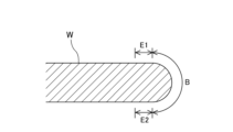
- FIG. 1A is an enlarged cross-sectional view showing the peripheral portion of the substrate.
- FIG. 1B is an enlarged cross-sectional view showing the peripheral portion of the substrate.
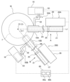
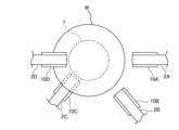
- FIG. 2 is a plan view showing one embodiment of the polishing apparatus.
- FIG. 3 is a side view seen from the direction indicated by arrow A in FIG.
- FIG. 4 is a side view seen from the direction indicated by arrow B in FIG.
- FIG. 5 is a diagram showing a state in which the bevel portion of the substrate is polished by the first polishing head.
- FIG. 6A is a diagram illustrating an embodiment of the polishing operation of the first polishing head.
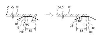
- FIG. 6B is a diagram illustrating an embodiment of the polishing operation of the second polishing head.
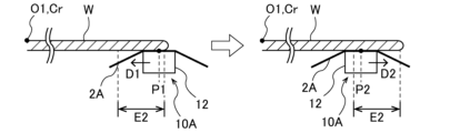
- FIG. 7A is a diagram showing another embodiment of the polishing operation of the first polishing head and the second polishing head.
- FIG. 7B is a diagram showing another embodiment of the polishing operation of the first polishing head and the second polishing head.
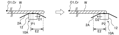
- FIG. 8A is a diagram showing another embodiment of the polishing operation of the first polishing head and the second polishing head.
- FIG. 8B is a diagram showing another embodiment of the polishing operation of the first polishing head and the second polishing head.
- FIG. 9A is a diagram showing another embodiment of the polishing operation of the first polishing head and the second polishing head.
- FIG. 9B is a diagram showing another embodiment of the polishing operation of the first polishing head and the second polishing head.
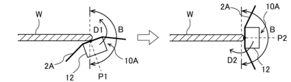
- FIG. 10A is a diagram illustrating an embodiment of the polishing operation of the first polishing head when polishing the bevel portion of the substrate.
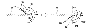
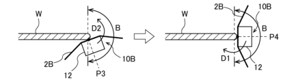
- FIG. 10B is a diagram illustrating an embodiment of the polishing operation of the second polishing head when polishing the bevel portion of the substrate.
- FIG. 11A is a diagram illustrating a polishing operation of a first polishing head and a second polishing head according to another embodiment.
- FIG. 11B is a diagram illustrating a polishing operation of a first polishing head and a second polishing head according to another embodiment.
- FIG. 12A is a diagram illustrating a polishing operation of a first polishing head and a second polishing head according to another embodiment.
- FIG. 12B is a diagram illustrating the polishing operation of the first polishing head and the second polishing head according to another embodiment.
- FIG. 13A is a diagram illustrating a polishing operation of a first polishing head and a second polishing head according to another embodiment.
- FIG. 13B is a diagram illustrating a polishing operation of a first polishing head and a second polishing head according to another embodiment.
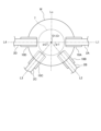
- FIG. 14 is a plan view showing another embodiment of the polishing apparatus.
- FIG. 15A is a diagram showing one embodiment of the polishing operation of the first to fourth polishing heads.
- FIG. 15B is a diagram showing one embodiment of the polishing operation of the first to fourth polishing heads.
- FIG. 15C is a diagram showing one embodiment of the polishing operation of the first to fourth polishing heads.
- FIG. 15D is a diagram showing an embodiment of the polishing operation of the first to fourth polishing heads.
- FIG. 16A is a diagram illustrating an example of another embodiment of the polishing operation of the first to fourth polishing heads.
- FIG. 16B is a diagram showing an example of another embodiment of the polishing operation of the first to fourth polishing heads.
- FIG. 16C is a diagram showing an example of another embodiment of the polishing operation of the first to fourth polishing heads.
- FIG. 16D is a diagram showing an example of another embodiment of the polishing operation of the first to fourth polishing heads.
- FIG. 17A is a diagram showing an example of another embodiment of the polishing operation of the first to fourth polishing heads.
- FIG. 17B is a diagram showing an example of another embodiment of the polishing operation of the first to fourth polishing heads.
- FIG. 17C is a diagram illustrating an example of another embodiment of the polishing operation of the first to fourth polishing heads.
- FIG. 17D is a diagram showing an example of another embodiment of the polishing operation of the first to fourth polishing heads.
- FIG. 18A is a diagram illustrating an example of another embodiment of the polishing operation of the first to fourth polishing heads.
- FIG. 18B is a diagram showing an example of another embodiment of the polishing operation of the first to fourth polishing heads.
- FIG. 18C is a diagram illustrating an example of another embodiment of the polishing operation of the first to fourth polishing heads.
- FIG. 18D is a diagram illustrating an example of another embodiment of the polishing operation of the first to fourth polishing heads.
- FIG. 18A is a diagram illustrating an example of another embodiment of the polishing operation of the first to fourth polishing heads.
- FIG. 18B is a diagram showing an example of another embodiment of the polishing operation of the first to fourth polishing heads.
- FIG. 18C is a diagram
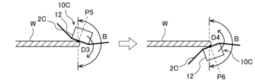
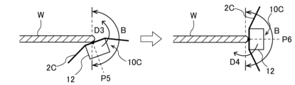
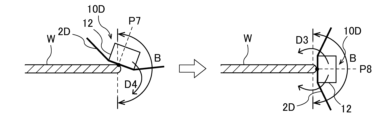
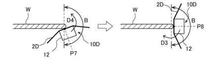
- FIG. 19A is a diagram showing an embodiment of the polishing operation of the first to fourth polishing heads when polishing a beveled portion of a substrate.
- FIG. 19B is a diagram illustrating an embodiment of the polishing operation of the first to fourth polishing heads when polishing the bevel portion of the substrate.
- FIG. 19C is a diagram illustrating an embodiment of the polishing operation of the first to fourth polishing heads when polishing the bevel portion of the substrate.
- FIG. 19D is a diagram illustrating an embodiment of the polishing operation of the first to fourth polishing heads when polishing the bevel portion of the substrate.
- FIG. 20A is a diagram showing an example of another embodiment of the polishing operation of the first to fourth polishing heads.
- FIG. 20B is a diagram showing an example of another embodiment of the polishing operation of the first to fourth polishing heads.
- FIG. 20C is a diagram showing an example of another embodiment of the polishing operation of the first to fourth polishing heads.
- FIG. 20D is a diagram showing an example of another embodiment of the polishing operation of the first to fourth polishing heads.
- FIG. 21A is a diagram showing an example of another embodiment of the polishing operation of the first to fourth polishing heads.
- FIG. 21B is a diagram showing an example of another embodiment of the polishing operation of the first to fourth polishing heads.
- FIG. 21C is a diagram illustrating an example of another embodiment of the polishing operation of the first to fourth polishing heads.
- FIG. 21D is a diagram showing an example of another embodiment of the polishing operation of the first to fourth polishing heads.
- FIG. 22A is a diagram showing an example of another embodiment of the polishing operation of the first to fourth polishing heads.
- FIG. 22B is a diagram showing an example of another embodiment of the polishing operation of the first to fourth polishing heads.
- FIG. 22C is a diagram illustrating an example of another embodiment of the polishing operation of the first to fourth polishing heads.
- FIG. 22D is a diagram showing an example of another embodiment of the polishing operation of the first to fourth polishing heads.
- FIG. 23A is a diagram for explaining still another embodiment in which the peripheral edge of a substrate is polished using four polishing heads.
- FIG. 23B is a diagram for explaining still another embodiment in which the peripheral edge of the substrate is polished with four polishing heads.
- FIG. 24 is a diagram showing how the peripheral edge of a substrate is polished with two polishing heads.
- FIG. 1A and 1B are enlarged cross-sectional views showing the peripheral portion of the substrate W.
- FIG. 1A is a sectional view of a so-called straight type substrate
- FIG. 1B is a sectional view of a so-called round type substrate.
- the bevel portion B has a chamfered shape or a rounded shape.
- the bevel portion B is the outermost periphery of the substrate W, which is composed of an upper inclined surface (upper bevel portion) B1, a lower inclined surface (lower bevel portion) B2, and a side portion (apex) B3. It is a surface.
- the bevel portion B is a portion that constitutes the outermost peripheral surface of the substrate W and has a curved cross section.
- the top edge portion E1 is an annular flat portion located inside the bevel portion B in the radial direction.
- the bottom edge portion E2 is an annular flat portion located on the opposite side from the top edge portion E1 and located inside the bevel portion B in the radial direction.
- the top edge portion E1 may include a region where a device is formed.
- the peripheral portion of the substrate W refers to a region including any one of the top edge portion E1, the bevel portion B, and the bottom edge portion E2.
- FIG. 2 is a plan view showing one embodiment of the polishing device.
- FIG. 3 is a side view seen from the direction indicated by arrow A in FIG.
- FIG. 4 is a side view seen from the direction indicated by arrow B in FIG.
- the polishing device is a device for polishing the peripheral edge of a substrate W such as a semiconductor wafer.
- the polishing apparatus includes a substrate holder 5, a first polishing head 10A, a second polishing head 10B, a first polishing tape supply mechanism 20A, a second polishing tape supply mechanism 20B, a lower supply nozzle 31, and an upper supply nozzle 32. ing.
- the substrate holding unit 5 includes a holding stage 7 that holds the substrate W by vacuum suction, a shaft 8 connected to the center of the holding stage 7, and a holding stage drive mechanism 9 that rotates and moves the holding stage 7 up and down.
- the holding stage drive mechanism 9 is configured to rotate the holding stage 7 around a predetermined rotation axis Cr and to be movable in the vertical direction along the predetermined rotation axis Cr.
- the axis passing through the center O1 of the substrate W and the predetermined rotation axis Cr substantially coincide with each other.
- the first polishing head 10A is configured to press the first polishing tape 2A against the peripheral edge of the substrate W to polish the peripheral edge of the substrate W.
- the second polishing head 10B is configured to press the second polishing tape 2B against the peripheral edge of the substrate W to polish the peripheral edge of the substrate W. Since the first polishing head 10A and the second polishing head 10B basically have the same configuration, the first polishing head 10A will be described below.
- the first polishing head 10A includes a pressing member 12 that presses the polishing surface of the first polishing tape 2A against the peripheral edge of the substrate W, and an air cylinder (drive mechanism) that moves the pressing member 12 toward the peripheral edge of the substrate W. It is equipped with 15. By controlling the air pressure supplied to the air cylinder 15, the pressing force of the first polishing tape 2A against the substrate W is adjusted.
- the pressing member 12 is arranged on the back side of the first polishing tape 2A (on the back side of the polishing surface having abrasive grains). When the pressing member 12 is moved toward the substrate W by the air cylinder 15, the pressing member 12 presses the first polishing tape 2A against the peripheral edge of the substrate W from the back side thereof. Thereby, the first polishing head 10A polishes the peripheral portion of the substrate W.
- an angle ⁇ 1 between a line L1 connecting the first polishing head 10A and the center O1 of the substrate W and a line L2 connecting the second polishing head 10B and the center O1 of the substrate W is 0 degrees. It is within 90 degrees from.
- the angle ⁇ 1 may be any angle smaller than 180 degrees, and may be, for example, 130 degrees, 50 degrees, or 0 degrees (i.e., a position where the first polishing head 10A and the second polishing head 10B overlap vertically). good.
- the first polishing tape supply mechanism 20A is configured to supply the first polishing tape 2A to the first polishing head 10A and collect it from the first polishing head 10A.
- the second polishing tape supply mechanism 20B is configured to supply the second polishing tape 2B to the second polishing head 10B and to collect it from the second polishing head 10B. Since the first polishing tape supply mechanism 20A and the second polishing tape supply mechanism 20B basically have the same configuration, the first polishing tape supply mechanism 20A will be described below.
- the first polishing tape supply mechanism 20A includes a tape unwinding reel 21, a tape take-up reel 22, and a plurality of guide rollers 24, 25, 26, and 27.
- the tape unwinding reel 21, the tape take-up reel 22, and the plurality of guide rollers 24, 25, 26, 27 are fixed to a reel base 28.
- the first polishing tape 2A is supplied to the first polishing head 10A so that the polishing surface of the first polishing tape 2A faces the peripheral edge of the substrate W.
- the traveling direction of the first polishing tape 2A is guided by guide rollers 24, 25, 26, and 27.
- Tension motors are connected to the tape unwinding reel 21 and the tape take-up reel 22, respectively.
- the tape unwinding reel 21 and the tape take-up reel 22 are fixed to a reel base 28 via a tension motor.
- Each tension motor is configured to apply a predetermined torque to the tape unwinding reel 21 and the tape take-up reel 22, and to apply a predetermined tension to the first polishing tape 2A.
- the lower supply nozzle 31 is configured to supply liquid to the lower surface of the substrate W.
- the upper supply nozzle 32 is configured to supply liquid to the upper surface of the substrate W.
- An example of the liquid supplied to the substrate W is pure water.
- the polishing apparatus further includes a first polishing head translational movement mechanism 40A as a first polishing head movement mechanism and a second polishing head translational movement mechanism 40B as a second polishing head movement mechanism.
- the first polishing head translation mechanism 40A is configured to translate the first polishing head 10A along the radial direction of the substrate W.
- the second polishing head translation mechanism 40B is configured to translate the second polishing head 10B along the radial direction of the substrate W. Since the first polishing head translational movement mechanism 40A and the second polishing head translational movement mechanism 40B basically have the same configuration, the first polishing head translational movement mechanism 40A will be described below.
- the first polishing head translation mechanism 40A includes a connecting member 43, a guide rail 44, a connecting shaft 46, and an air cylinder (drive mechanism) 47.
- the first polishing head translation mechanism 40A is connected to the first polishing head 10A and the first polishing tape supply mechanism 20A via a movable plate 41. More specifically, the polishing head support member 18 connected to the first polishing head 10A and the reel base 28 of the first polishing tape supply mechanism 20A are connected to the upper surface of the movable plate 41, and the first polishing head is translated.
- the moving mechanism 40A is connected to the lower surface of the movable plate 41. The entire first polishing head 10A and first polishing tape supply mechanism 20A are movable together with the movable plate 41.
- the guide rail 44 extends in the same direction as the line connecting the predetermined rotation axis Cr on the holding stage 7 (i.e., the center O1 of the substrate W) and the first polishing head 10A, and is fixed to the base plate 48. .
- the air cylinder 47 is connected to the movable plate 41 via a connecting member 43 and a connecting shaft 46, and is fixed to a base plate 48.
- the first polishing head translation mechanism 40A drives the air cylinder 47 to move the movable plate 41 along the guide rail 44 at a predetermined movement speed, thereby moving the first polishing head 10A and the first polishing tape supply mechanism 20A.
- a predetermined moving speed in a direction approaching a predetermined rotational axis Cr of the substrate W (i.e., the center O1 of the substrate W) and in a direction away from the predetermined rotational axis Cr (i.e., the center O1 of the substrate W). I can do it.
- the first polishing head 10A is moved in the direction approaching the predetermined rotation axis Cr of the substrate W (i.e., the center O1 of the substrate W) and in the direction away from the predetermined rotation axis Cr (i.e., the center O1 of the substrate W).
- the specific configuration of the first polishing head translation mechanism 40A is not limited to the present embodiment, as long as it is possible to do so.
- the polishing apparatus further includes a first polishing head tilting mechanism 50A as a first polishing head moving mechanism and a second polishing head tilting mechanism 50B as a second polishing head moving mechanism.
- the first polishing head tilting mechanism 50A is connected to the first polishing head 10A
- the second polishing head tilting mechanism 50B is connected to the second polishing head 10B.
- the first polishing head tilting mechanism 50A is configured to tilt the first polishing head 10A with respect to the substrate holding surface of the holding stage 7.
- the second polishing head tilting mechanism 50B is configured to tilt the second polishing head 10B with respect to the substrate holding surface of the holding stage 7. Since the first polishing head tilting mechanism 50A and the second polishing head tilting mechanism 50B basically have the same configuration, the first polishing head tilting mechanism 50A will be described below.
- the first polishing head tilting mechanism 50A includes a crank arm 52 connected to the first polishing head 10A, and an arm rotation device 53 that rotates the crank arm 52.
- One end of the crank arm 52 is located at substantially the same height as the substrate holding surface of the holding stage 7 and is connected to an arm rotation device 53.
- the other end of the crank arm 52 is connected to the first polishing head 10A.
- the arm rotation device 53 is disposed inside the polishing head support member 18 , and the crank arm 52 extends through the polishing head support member 18 .
- the first polishing head tilting mechanism 50A tilts the entire first polishing head 10A with respect to the substrate W on the substrate holding surface of the holding stage 7 at a predetermined tilting speed. can be done. Furthermore, the first polishing head tilting mechanism 50A is configured to be able to maintain the first polishing head 10A at a predetermined inclination angle. Note that the specific configuration of the first polishing head tilting mechanism 50A is not limited to this embodiment, as long as the first polishing head 10A can be tilted with respect to the substrate holding surface of the holding stage 7 and the substrate W.
- the first polishing head 10A shown in FIG. 3 is tilted so that the top edge portion E1 of the substrate W (see FIGS. 1A and 1B) can be polished by the first polishing head tilting mechanism 50A.
- the second polishing head 10B shown in FIG. 4 is tilted so that the bottom edge portion E2 (see FIGS. 1A and 1B) of the substrate W can be polished by the second polishing head tilting mechanism 50B.
- FIG. 5 is a diagram showing how the bevel portion B (see FIGS. 1A and 1B) of the substrate W is being polished by the first polishing head 10A.
- the first polishing head tilting mechanism 50A can polish the bevel portion B of the substrate W by continuously changing the inclination angle of the first polishing head 10A. In this way, the first polishing head 10A and the second polishing head 10B are tilted by the first polishing head tilting mechanism 50A and the second polishing head tilting mechanism 50B, so that the top edge portion E1, which is the peripheral edge of the substrate W, , the bottom edge portion E2, and the bevel portion B can be polished.
- the polishing apparatus of this embodiment includes a first polishing head translation mechanism 40A and a first polishing head tilting mechanism 50A as a first polishing head movable mechanism, and a second polishing head translation mechanism as a second polishing head movable mechanism.
- the polishing apparatus includes the moving mechanism 40B and the second polishing head tilting mechanism 50B
- the polishing apparatus includes only the first polishing head translation mechanism 40A as the first polishing head movable mechanism, and the second polishing head movable mechanism 40B. It may be configured to include only the second polishing head translation mechanism 40B as a mechanism and to polish only the top edge portion E1 or the bottom edge portion B2 of the peripheral edge portion of the substrate W.
- the polishing apparatus further includes an operation control section 80 that controls the operation of the polishing apparatus.
- the mechanism 40A, the second polishing head translation mechanism 40B, the first polishing head tilting mechanism 50A, and the second polishing head tilting mechanism 50B are electrically connected to the operation control section 80.
- Substrate holder 5 first polishing head 10A, second polishing head 10B, first polishing tape supply mechanism 20A, second polishing tape supply mechanism 20B, lower supply nozzle 31, upper supply nozzle 32, first polishing head translational movement
- the operations of the mechanism 40A, the second polishing head translation mechanism 40B, the first polishing head tilting mechanism 50A, and the second polishing head tilting mechanism 50B are controlled by the operation control unit 80.
- the operation control unit 80 includes at least one computer.
- the operation control unit 80 includes a storage device 80a that stores programs, and an arithmetic device 80b that executes calculations according to the programs.
- the storage device 80a includes a main storage device (for example, random access memory) that can be accessed by the arithmetic device 80b, and an auxiliary storage device (for example, a hard disk drive or solid state drive) that stores programs.
- the arithmetic device 80b includes a CPU (central processing unit), a GPU (graphic processing module), or the like that performs arithmetic operations according to instructions included in a program stored in the storage device 80a.
- the specific configuration of the operation control section 80 is not limited to these examples.
- the polishing apparatus of this embodiment simultaneously drives the first polishing head 10A and the second polishing head 10B to simultaneously polish the peripheral portion of the substrate W. Polishing of the peripheral edge of the substrate W is performed as follows.
- the operation control section 80 issues a command to the holding stage drive mechanism 9 of the substrate holding section 5 to raise the holding stage 7.
- the substrate W is placed on the substrate holding surface of the holding stage 7 and held by vacuum suction.
- the operation control unit 80 issues a command to the holding stage drive mechanism 9 of the substrate holding unit 5 to lower the substrate W to the polishing position and rotate the holding stage 7 and the substrate W. Further, the operation control unit 80 issues a command to the lower supply nozzle 31 and the upper supply nozzle 32 to supply liquid from the lower supply nozzle 31 and the upper supply nozzle 32.
- the operation control unit 80 issues a command to the first polishing tape supply mechanism 20A to start supplying the first polishing tape 2A to the first polishing head 10A, and issues a command to the second polishing tape supply mechanism 20B. Then, supply of the second polishing tape 2B to the second polishing head 10B is started. Thereafter, the operation control unit 80 issues a command to the air cylinder 15 of the first polishing head 10A to press the first polishing tape 2A against the peripheral edge of the substrate W with the pressing member 12 of the first polishing head 10A, and A command is issued to the air cylinder 15 of the polishing head 10B to press the second polishing tape 2B against the peripheral edge of the substrate W using the pressing member 12 of the second polishing head 10B.
- the operation control unit 80 issues a command to the first polishing head translation mechanism 40A to move the first polishing tape 2A to the substrate with the first polishing head 10A. While moving the first polishing head 10A while being pressed against either the top edge portion E1 or the bottom edge portion E2 of the W, a command is issued to the second polishing head translation mechanism 40B to perform the second polishing. The second polishing head 10B is moved with the head 10B pressing the second polishing tape 2B against the other of the top edge portion E1 and bottom edge portion E2 of the substrate W.
- the operation control unit 80 issues a command to the first polishing head tilting mechanism 50A to press the first polishing tape 2A against the bevel portion B of the substrate W with the first polishing head 10A.
- a command is issued to the second polishing head tilting mechanism 50B so that the second polishing tape 2B is pressed against the bevel portion B of the substrate W by the second polishing head 10B. , tilting the second polishing head 10B.
- the operation control unit 80 issues a command to the polishing device to finish polishing the substrate W. Specifically, the operation control unit 80 stops the operations of the first polishing head translation mechanism 40A and the second polishing head translation mechanism 40B, or the first polishing head tilting mechanism 50A and the second polishing head tilting mechanism 50B. , the driving of the air cylinder 15 of the first polishing head 10A and the air cylinder 15 of the second polishing head 10B is stopped, and the pressing member 12 of the first polishing head 10A and the pressing member 12 of the second polishing head 10B are removed from the substrate W. Separate. After that, the operation control unit 80 stops the operations of the substrate holding unit 5, the first polishing tape supply mechanism 20A, the second polishing tape supply mechanism 20B, the lower supply nozzle 31, and the upper supply nozzle 32, and removes the substrate W. Finish polishing.
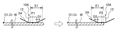
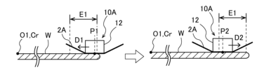
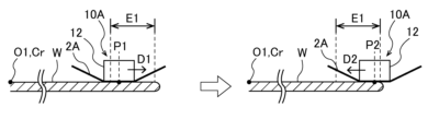
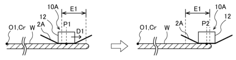
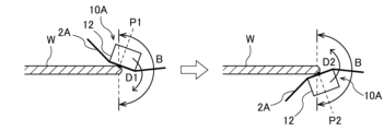
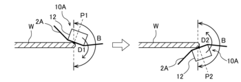
- FIG. 6A is a diagram showing one embodiment of the polishing operation of the first polishing head 10A
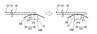
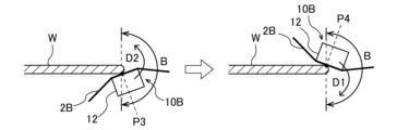
- FIG. 6B is a diagram showing one embodiment of the polishing operation of the second polishing head 10B.
- the polishing apparatus of this embodiment polishes the bottom edge portion E2 of the substrate W using the second polishing head 10B while polishing the top edge portion E1 of the substrate W using the first polishing head 10A.
- 6A and 6B are enlarged schematic diagrams of the contact portions between the top edge portion E1 of the substrate W and the first polishing tape 2A, and between the bottom edge portion E2 and the second polishing tape 2B.
- the first polishing region polished by the first polishing head 10A is the region between the first polishing point P1 and the second polishing point P2 within the top edge portion E1 of the substrate W.
- the first polishing point P1 is located closer to the center O1 of the substrate W (that is, the predetermined rotation axis Cr) than the second polishing point P2.
- the second polishing region polished by the second polishing head 10B is an area between the third polishing point P3 and the fourth polishing point P4 within the bottom edge portion E2 of the substrate W.
- the third polishing point P3 is located further from the center O1 of the substrate W (ie, the predetermined rotation axis Cr) than the fourth polishing point P4.
- the first polishing region and the second polishing region are located on opposite sides. That is, the first polishing point P1 and the second polishing point P2, which are both ends of the first polishing area, and the third polishing point P3, and fourth polishing point P4, which are both ends of the second polishing area, are located on opposite sides. ing.
- the distance from the center O1 of the substrate W (i.e., the predetermined rotational axis Cr) of the first polishing point P1 and the distance from the center O1 (i.e., the predetermined rotational axis Cr) of the substrate W of the fourth polishing point P4 are equal.
- the distance from the center O1 of the substrate W (i.e., the predetermined rotational axis Cr) of the second polishing point P2 and the distance from the center O1 (i.e., the predetermined rotational axis Cr) of the substrate W of the third polishing point P3 are equal. That is, the lengths of the first polishing region and the second polishing region in the radial direction of the substrate W are equal.
- the first polishing head 10A presses the first polishing tape 2A against the first polishing point P1 and starts polishing the first polishing area.
- the first polishing head translation mechanism 40A moves the first polishing head 10A in the first direction D1 to the second polishing point P2. move it to
- the first direction D1 is a direction away from the center O1 of the substrate W in the radial direction of the substrate W, that is, a direction away from the predetermined rotation axis Cr.
- the first polishing head translation mechanism 40A moves the first polishing head 10A in the second direction D2 to the first polishing point P1. move it.
- the second direction D2 is a direction approaching the center O1 of the substrate W in the radial direction of the substrate W, that is, a direction approaching the predetermined rotation axis Cr.
- the first direction D1 and the second direction D2 are opposite directions.
- the first polishing head 10A reciprocates the first polishing area once.
- the first polishing head 10A may be further moved in the first direction D1 and the polishing operation shown in FIG. 6A may be repeated to reciprocate and polish the first polishing region multiple times.
- the first polishing area may be polished one way without moving the first polishing head 10A in the second direction D2.
- the second polishing head 10B presses the second polishing tape 2B against the third polishing point P3 and starts polishing the second polishing area.
- the second polishing head translation mechanism 40B moves the second polishing head 10B in the second direction D2 to the fourth polishing point P4. move it to The second direction D2 is the same as the second direction D2 described with reference to FIG. 6A.
- the second polishing head translation mechanism 40B moves the second polishing head 10B in the first direction D1 to the third polishing point P3. move it.
- the first direction D1 is the same as the first direction D1 described with reference to FIG. 6A.
- the second polishing head 10B reciprocates the second polishing area once.
- the second polishing head 10B may be further moved in the second direction D2 and the polishing operation shown in FIG. 6B may be repeated to polish the second polishing region back and forth a plurality of times.
- the second polishing area may be polished one way without moving the second polishing head 10B in the first direction D1.
- the first polishing head 10A and the second polishing head 10B simultaneously polish the first polishing region of the top edge portion E1 and the second polishing region of the bottom edge portion E2.
- the timing of pressing and starting polishing of the second polishing area may be simultaneous.
- the moving speeds of the first polishing head 10A and the second polishing head 10B are equal, and the timing when the first polishing head 10A reaches the second polishing point P2 and the timing when the second polishing head 10B reaches the fourth polishing point P4 are different.
- the timing at which the first polishing head 10A and the second polishing head 10B turn back and the first polishing head 10A returns to the first polishing point P1 and the timing at which the second polishing head 10B returns to the third polishing point P3 are at the same time. It may be. Furthermore, at the end of polishing, the timing at which the pressing member 12 of the first polishing head 10A is separated from the substrate W and the timing at which the pressing member 12 of the second polishing head 10B is separated from the substrate W may be the same.
- the first polishing head 10A and the second polishing head 10B simultaneously polish the first polishing region of the top edge portion E1 and the second polishing region of the bottom edge portion E2, so that a single polishing head is used. Compared to the case where the top edge portion E1 and the bottom edge portion E2 are polished, the overall polishing processing time can be shortened.
- first polishing region and the second polishing region are located on opposite sides, and the first polishing head 10A and the second polishing head 10B are arranged in the first direction D1 and the second direction D1, which are opposite directions. Since the substrate W is polished while moving in the direction D2, the pressing force by the first polishing head 10A and the pressing force by the second polishing head 10B are applied in opposite directions. Therefore, as described with reference to FIG. 24, the pressing force by the first polishing head 10A and the second polishing head 10B is not excessively applied to the peripheral edge of the substrate W, and warpage of the substrate W is suppressed. be able to.
- the first polishing head 10A and the second polishing head 10B polish the substrate W while moving in the first direction D1 and the second direction D2, which are opposite directions.
- the substrate W moves together with the first polishing head 10A and the second polishing head 10B.
- positional displacement with respect to the substrate holder 5 can be prevented.
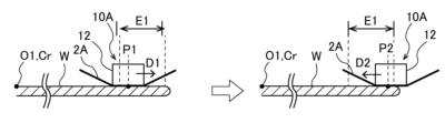
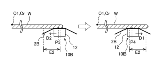
- FIGS. 7A to 9B are diagrams showing other embodiments of the polishing operation of the first polishing head 10A and the second polishing head 10B.
- the configurations and operations of these embodiments, which are not particularly described, are the same as those of the embodiments described with reference to FIGS. 6A and 6B, and thus redundant explanations thereof will be omitted.
- the first polishing area is the top edge E1 of the periphery of the substrate W
- the second polishing area is the bottom edge E2 of the periphery of the substrate W.
- the first polishing region is one of the top edge portion E1 and the bottom edge portion E2
- the second polishing region is the top edge portion E1 and the bottom edge portion E2. It may be the other one of the bottom edge portions E2.
- the first direction D1 is a direction away from the center O1 of the substrate W (i.e., the predetermined rotation axis Cr) in the radial direction of the substrate W.
- the second direction D2 was a direction approaching the center O1 of the substrate W (i.e., the predetermined rotation axis Cr) in the radial direction of the substrate W.
- 1 direction D1 is a direction approaching the center O1 of the substrate W (i.e., a predetermined rotational axis Cr) and a direction away from the center O1 of the substrate W (i.e., a predetermined rotational axis Cr) in the radial direction of the substrate W.
- the second direction D2 is a direction approaching the center O1 of the substrate W (i.e., a predetermined rotation axis Cr) in the radial direction of the substrate W, and a direction approaching the center O1 of the substrate W ( That is, it may be the other direction away from the predetermined rotation axis Cr).
- the first polishing region polished by the first polishing head 10A is the top edge portion E1, and the first polishing point P1 and the second polishing point P2 are within the top edge portion E1. It is in.
- the first polishing point P1 is located further from the center O1 of the substrate W (ie, the predetermined rotation axis Cr) than the second polishing point P2.
- the second polishing region polished by the second polishing head 10B is the bottom edge portion E2, and the third polishing point P3 and the fourth polishing point P4 are located within the bottom edge portion E2.
- the third polishing point P3 is located closer to the center O1 of the substrate W (ie, the predetermined rotational axis Cr) than the fourth polishing point P4.
- the first direction D1 is a direction approaching the center O1 of the substrate W in the radial direction of the substrate W, that is, a direction approaching a predetermined rotation axis Cr.
- the second direction D2 is a direction away from the center O1 of the substrate W in the radial direction of the substrate W, that is, a direction away from the predetermined rotation axis Cr.
- the first polishing area polished by the first polishing head 10A is the bottom edge portion E2, and the first polishing point P1 and the second polishing point P2 are inside the bottom edge portion E2. It is in.
- the first polishing point P1 is located further from the center O1 of the substrate W (ie, the predetermined rotation axis Cr) than the second polishing point P2.
- the second polishing region polished by the second polishing head 10B is the top edge portion E1, and the third polishing point P3 and the fourth polishing point P4 are located within the top edge portion E1.
- the third polishing point P3 is located closer to the center O1 of the substrate W (ie, the predetermined rotational axis Cr) than the fourth polishing point P4.
- the first direction D1 is a direction approaching the center O1 of the substrate W in the radial direction of the substrate W, that is, a direction approaching a predetermined rotation axis Cr.
- the second direction D2 is a direction away from the center O1 of the substrate W in the radial direction of the substrate W, that is, a direction away from the predetermined rotation axis Cr.
- the first polishing area polished by the first polishing head 10A is the bottom edge portion E2, and the first polishing point P1 and the second polishing point P2 are inside the bottom edge portion E2. It is in.
- the first polishing point P1 is located closer to the center O1 of the substrate W (that is, the predetermined rotation axis Cr) than the second polishing point P2.
- the second polishing region polished by the second polishing head 10B is the top edge portion E1, and the third polishing point P3 and the fourth polishing point P4 are located within the top edge portion E1.
- the third polishing point P3 is located further from the center O1 of the substrate W (ie, the predetermined rotation axis Cr) than the fourth polishing point P4.
- the first direction D1 is a direction away from the center O1 of the substrate W in the radial direction of the substrate W, that is, a direction away from the predetermined rotation axis Cr.
- the second direction D2 is a direction approaching the center O1 of the substrate W in the radial direction of the substrate W, that is, a direction approaching the predetermined rotation axis Cr.
- FIG. 10A is a diagram showing an embodiment of the polishing operation of the first polishing head 10A when polishing the bevel portion B of the substrate W
- FIG. It is a figure showing one embodiment of polishing operation of polishing head 10B.
- the configuration and operation of this embodiment, which are not particularly described, are the same as those of the embodiment described with reference to FIG. 6A and FIG. 6B, so the redundant description thereof will be omitted.
- the first polishing area polished by the first polishing head 10A is the area between the first polishing point P1 and the second polishing point P2 in the bevel portion B of the substrate W.
- the first polishing point P1 is located above the second polishing point P2 in the bevel portion B.
- the second polishing area polished by the second polishing head 10B is an area between the third polishing point P3 and the fourth polishing point P4 in the bevel portion B of the substrate W.
- the third polishing point P3 is located lower in the bevel portion B than the fourth polishing point P4.
- the first polishing point P1 is one of both ends of the first polishing area where polishing is started by the first polishing head 10A
- the second polishing area is where polishing is started by the second polishing head 10B.
- the third polishing point P3, which is one end of both ends, is located on the opposite side of the bevel portion B.
- the second polishing point P2, which is the other end of the first polishing region, and the fourth polishing point P4, which is the other end of the second polishing region are located on opposite sides of the bevel portion B. positioned.
- the first polishing area polished by the first polishing head 10A and the second polishing area polished by the second polishing head 10B substantially match. That is, the first polishing point P1 and the fourth polishing point P4 substantially match, and the second polishing point P2 and the third polishing point P3 substantially match.
- the first polishing head 10A presses the first polishing tape 2A against the first polishing point P1 and starts polishing the first polishing area.
- the first polishing head tilting mechanism 50A moves the first polishing head 10A in the first direction D1 to the second polishing point P2. Tilt it.
- the first direction D1 is a direction from the upper side of the bevel portion B to the lower side.
- the first polishing head tilting mechanism 50A tilts the first polishing head 10A in the second direction D2 to the first polishing point P1.
- the second direction D2 is a direction from the lower side of the bevel portion B to the upper side.
- the first direction D1 and the second direction D2 are opposite directions.
- the first polishing head 10A reciprocates the first polishing area once.
- the first polishing head 10A may be further tilted in the first direction D1 and the polishing operation shown in FIG. 10A may be repeated to polish the first polishing region back and forth a plurality of times.
- the first polishing area may be polished one way without tilting the first polishing head 10A in the second direction D2.
- the second polishing head 10B presses the second polishing tape 2B against the third polishing point P3 and starts polishing the second polishing area.
- the second polishing head tilting mechanism 50B moves the second polishing head 10B in the second direction D2 to the fourth polishing point P4. Tilt it.
- the second direction D2 is the same as the second direction D2 described with reference to FIG. 10A.
- the second polishing head tilting mechanism 50B tilts the second polishing head 10B in the first direction D1 to the third polishing point P3.
- the first direction D1 is the same as the first direction D1 described with reference to FIG. 10A.
- the second polishing head 10B reciprocates the second polishing area once.
- the second polishing head 10B may be further tilted in the second direction D2 and the polishing operation shown in FIG. 10B may be repeated to reciprocate and polish the second polishing region multiple times.
- the second polishing area may be polished one way without tilting the second polishing head 10B in the first direction D1.
- the first polishing head 10A and the second polishing head 10B simultaneously polish the first polishing region and the second polishing region of the bevel portion B.
- the timing of pressing and starting polishing of the second polishing area may be simultaneous.
- the tilting speeds of the first polishing head 10A and the second polishing head 10B are equal, and the timing when the first polishing head 10A reaches the second polishing point P2 and the timing when the second polishing head 10B reaches the fourth polishing point P4 are different. , may be simultaneous.
- the timing at which the first polishing head 10A and the second polishing head 10B turn back and the first polishing head 10A returns to the first polishing point P1 and the timing at which the second polishing head 10B returns to the third polishing point P3 are at the same time. It may be. Furthermore, at the end of polishing, the timing at which the pressing member 12 of the first polishing head 10A is separated from the substrate W and the timing at which the pressing member 12 of the second polishing head 10B is separated from the substrate W may be the same.
- the first polishing head 10A and the second polishing head 10B simultaneously polish the bevel portion B, so the overall polishing processing time is shorter than when polishing the bevel portion B with one polishing head. can be shortened.
- first polishing point P1 where polishing is started by the first polishing head 10A and the third polishing point P3 where polishing is started by the second polishing head 10B are located on opposite sides in the bevel portion B, Since the first polishing head 10A and the second polishing head 10B polish the substrate W while tilting in the first direction D1 and the second direction D2, which are opposite directions, the pressing force by the first polishing head 10A and The pressing force by the second polishing head 10B is applied to the bevel portion B in the opposite direction. Therefore, as described with reference to FIG. 24, the pressing force by the first polishing head 10A and the second polishing head 10B is not excessively applied to the peripheral edge of the substrate W, and warpage of the substrate W is suppressed. be able to.
- 11A to 13B are diagrams showing other embodiments of the polishing operation of the first polishing head 10A and the second polishing head 10B.
- the configurations and operations of these embodiments, which are not particularly described, are the same as those of the embodiments described with reference to FIGS. 10A and 10B, and thus redundant description thereof will be omitted.
- the first direction D1 is from the upper side of the beveled part B to the lower side
- the second direction D2 is from the lower side of the beveled part B.
- the first direction D1 is a direction from the upper side of the beveled portion B to the lower side and a direction from the lower side of the beveled portion B to the upper side.
- the second direction D2 may be the other of the direction from the upper side of the bevel part B to the lower side and the direction from the lower side of the bevel part B to the upper side.
- the first polishing area polished by the first polishing head 10A is the bevel portion B, and the first polishing point P1 and the second polishing point P2 are within the bevel portion B. .
- the first polishing point P1 is located lower in the bevel portion B than the second polishing point P2.
- the second polishing region polished by the second polishing head 10B is the bevel portion B, and the third polishing point P3 and the fourth polishing point P4 are within the bevel portion B.
- the third polishing point P3 is located above the fourth polishing point P4 in the bevel portion B.
- the first direction D1 is a direction from the lower side of the bevel portion B to the upper side.
- the second direction D2 is a direction from the upper side of the bevel portion B to the lower side.
- the first polishing region polished by the first polishing head 10A is the upper region of the bevel portion B, and the first polishing point P1 and the second polishing point P2 are It is in section B.
- the first polishing point P1 is located above the second polishing point P2 in the bevel portion B, and the second polishing point P2 is located in the center of the bevel portion B.
- the second polishing region polished by the second polishing head 10B is the lower region of the bevel portion B, and the third polishing point P3 and the fourth polishing point P4 are located within the bevel portion B.
- the third polishing point P3 is located lower in the bevel portion B than the fourth polishing point P4, and the fourth polishing point P4 is located in the center of the bevel portion B.
- the first direction D1 is a direction from the upper side of the bevel portion B to the lower side.
- the second direction D2 is a direction from the lower side of the bevel portion B to the upper side. In this way, the first polishing head 10A and the second polishing head 10B may polish different areas within the bevel portion B.
- the first polishing region polished by the first polishing head 10A is the lower region of the bevel portion B, and the first polishing point P1 and the second polishing point P2 are It is located inside the bevel part B.
- the first polishing point P1 is located lower in the bevel portion B than the second polishing point P2, and the second polishing point P2 is located in the center of the bevel portion B.
- the second polishing region polished by the second polishing head 10B is the upper region of the bevel portion B, and the third polishing point P3 and the fourth polishing point P4 are within the bevel portion B.
- the third polishing point P3 is located above the fourth polishing point P4 in the bevel portion B, and the fourth polishing point P4 is located in the center of the bevel portion B.
- the first direction D1 is a direction from the lower side of the bevel portion B to the upper side.
- the second direction D2 is a direction from the upper side of the bevel portion B to the lower side. In this way, the first polishing head 10A and the second polishing head 10B may polish different areas within the bevel portion B.
- FIG. 14 is a plan view showing another embodiment of the polishing device.
- the polishing apparatus of this embodiment includes a third polishing head 10C and a fourth polishing head 10D in addition to a first polishing head 10A and a second polishing head 10B.
- the configuration of the polishing apparatus of this embodiment which is not particularly described, is the same as the configuration of the polishing apparatus described with reference to FIGS. 2 to 5, and therefore, the redundant explanation will be omitted.
- the polishing apparatus of this embodiment includes a third polishing tape supply mechanism (not shown) that supplies the third polishing tape 2C to the third polishing head 10C and collects the third polishing tape 2C from the third polishing head 10C, and a fourth polishing tape 2D.
- a fourth polishing tape supply mechanism (not shown) that supplies the tape to and collects it from the fourth polishing head 10D, and a third polishing head translation mechanism (not shown) that serves as a third polishing head movable mechanism.
- the third polishing head translation mechanism is configured to translate the third polishing head 10C along the radial direction of the substrate W.
- the fourth polishing head translation mechanism is configured to translate the fourth polishing head 10D along the radial direction of the substrate W.
- the third polishing head tilting mechanism is configured to tilt the third polishing head 10C with respect to the substrate holding surface of the holding stage 7.
- the fourth polishing head tilting mechanism is configured to tilt the fourth polishing head 10D with respect to the substrate holding surface of the holding stage 7.
- the third polishing head 10C and the fourth polishing head 10D have basically the same configuration as the first polishing head 10A.
- the third polishing tape supply mechanism and the fourth polishing tape supply mechanism have basically the same configuration as the first polishing tape supply mechanism 20A.
- the third polishing head translation mechanism and the fourth polishing head translation mechanism basically have the same configuration as the first polishing head translation mechanism 40A.
- the third polishing head tilting mechanism and the fourth polishing head tilting mechanism basically have the same configuration as the first polishing head tilting mechanism 50A. Therefore, these redundant explanations will be omitted.
- an angle ⁇ 1 formed by a line L1 connecting the first polishing head 10A and the center O1 of the substrate W and a line L2 connecting the second polishing head 10B and the center O1 of the substrate W is 0 degrees. It is within 90 degrees from.
- the angle ⁇ 2 formed by the line L3 connecting the third polishing head 10C and the center O1 of the substrate W and the line L4 connecting the fourth polishing head 10D and the center O1 of the substrate W is within the range of 0 degrees to 90 degrees. be.
- the first polishing head 10A and the fourth polishing head 10D are arranged symmetrically with respect to a line Lc passing through the center O1 of the substrate W and perpendicular to a predetermined rotation axis Cr.
- the second polishing head 10B and the third polishing head 10C are arranged symmetrically with respect to a line Lc passing through the center O1 of the substrate W and perpendicular to a predetermined rotation axis Cr.
- the positional relationship between the first polishing head 10A, the second polishing head 10B, the third polishing head 10C, and the fourth polishing head 10D is true as long as the angle ⁇ 1 and the angle ⁇ 2 are within the range of 0 degrees to 90 degrees. It is not limited to the embodiment.
- FIGS. 15A to 15D are diagrams showing an embodiment of the polishing operation of the first polishing head 10A to the fourth polishing head 10D.
- the top edge portion E1 of the substrate W is polished by the first polishing head 10A and the fourth polishing head 10D
- the bottom edge portion E2 of the substrate W is polished by the second polishing head 10B and the third polishing head 10C. do.
- the polishing operations of the first polishing head 10A and the second polishing head 10B shown in FIGS. 15A and 15B are the same as the polishing operations of the first polishing head 10A and the second polishing head 10B described with reference to FIGS. 6A and 6B. Therefore, the redundant explanation will be omitted.
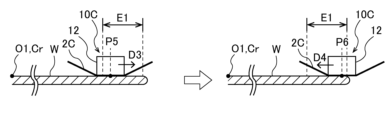
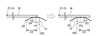
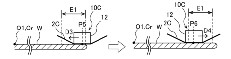
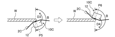
- the third polishing region polished by the third polishing head 10C is the region between the fifth polishing point P5 and the sixth polishing point P6 in the bottom edge portion E2 of the substrate W.
- the fifth polishing point P5 is located further from the center O1 of the substrate W (that is, the predetermined rotation axis Cr) than the sixth polishing point P6.
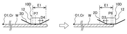
- the fourth polishing region polished by the fourth polishing head 10D is an area between the seventh polishing point P7 and the eighth polishing point P8 within the top edge portion E1 of the substrate W.
- the seventh polishing point P7 is located closer to the center O1 of the substrate W (ie, the predetermined rotation axis Cr) than the eighth polishing point P8.
- the third polishing area polished by the third polishing head 10C and the fourth polishing area polished by the fourth polishing head 10D are located on opposite sides. That is, the fifth polishing point P5 and the sixth polishing point P6, which are both ends of the third polishing area, and the seventh polishing point P7, and the eighth polishing point P8, which are both ends of the fourth polishing area, are located on the opposite side. ing.
- the distance from the center O1 of the substrate W (i.e., the predetermined rotation axis Cr) of the fifth polishing point P5 and the distance from the center O1 of the substrate W (i.e., the predetermined rotation axis Cr) of the eighth polishing point P8 are equal.
- the distance from the center O1 of the substrate W (i.e., the predetermined rotation axis Cr) of the sixth polishing point P6 and the distance from the center O1 (i.e., the predetermined rotation axis Cr) of the substrate W of the seventh polishing point P7 are equal. That is, the lengths of the third polishing region and the fourth polishing region in the radial direction of the substrate W are equal.
- the third polishing head 10C presses the third polishing tape 2C against the fifth polishing point P5 and starts polishing the third polishing area.
- the third polishing head translation mechanism moves the third polishing head 10C in the third direction D3 to the sixth polishing point P6. move it.
- the third direction D3 is a direction approaching the center O1 of the substrate W in the radial direction of the substrate W, that is, a direction approaching the predetermined rotation axis Cr.
- the third polishing head 10C is moved in the fourth direction D4 to the fifth polishing point P5 by the third polishing head translation mechanism.
- the fourth direction D4 is a direction away from the center O1 of the substrate W in the radial direction of the substrate W, that is, a direction away from the predetermined rotation axis Cr.
- the third direction D3 and the fourth direction D4 are opposite directions.
- the third polishing head 10C reciprocates the third polishing area once.
- the third polishing head 10C may be further moved in the third direction D3 and the polishing operation shown in FIG. 15C may be repeated to reciprocate and polish the third polishing region multiple times.
- the third polishing region may be polished one way without moving the third polishing head 10C in the fourth direction D4.
- the fourth polishing head 10D presses the fourth polishing tape 2D against the seventh polishing point P7 and starts polishing the fourth polishing area.
- the fourth polishing head translation mechanism moves the fourth polishing head 10D in the fourth direction D4 to the eighth polishing point P8. move it.
- the fourth direction D4 is the same as the fourth direction D4 described with reference to FIG. 15C.
- the fourth polishing head translation mechanism moves the fourth polishing head 10D in the third direction D3 to the seventh polishing point P7.
- the third direction D3 is the same as the third direction D3 described with reference to FIG. 15C.
- the fourth polishing head 10D reciprocates the fourth polishing region once.
- the fourth polishing head 10D may be further moved in the fourth direction D4 and the polishing operation shown in FIG. 15D may be repeated to reciprocate and polish the fourth polishing region multiple times.
- the fourth polishing region may be polished one way without moving the fourth polishing head 10D in the third direction D3.
- the first polishing area polished by the first polishing head 10A and the fourth polishing area polished by the fourth polishing head 10D substantially match
- the second polishing area polished by the second polishing head 10B The area and the third polishing area polished by the third polishing head 10C substantially match.
- the first direction D1 and the fourth direction D4 substantially match
- the second direction D2 and the third direction D3 substantially match.
- the first polishing head 10A to the fourth polishing head 10D simultaneously polish the first polishing region and fourth polishing region of the top edge portion E1, and the second polishing region and third polishing region of the bottom edge portion E2.
- the timing at which the third polishing head 10C presses the third polishing tape 2C to start polishing the second polishing area, the timing at which the third polishing head 10C presses the third polishing tape 2C against the fifth polishing point P5 and starts polishing the third polishing area, and the fourth polishing head The timing at which the polishing tape 10D presses the fourth polishing tape 2D against the seventh polishing point P7 and starts polishing the fourth polishing area may be at the same time.
- the moving speeds of the first polishing head 10A, the second polishing head 10B, the third polishing head 10C, and the fourth polishing head 10D are equal, and the timing at which the first polishing head 10A reaches the second polishing point P2 and the timing at which the second polishing
- the timing at which the head 10B reaches the fourth polishing point P4, the timing at which the third polishing head 10C reaches the sixth polishing point P6, and the timing at which the fourth polishing head 10D reaches the eighth polishing point P8 are simultaneous. There may be.
- the timing at which the first polishing head 10A, the second polishing head 10B, the third polishing head 10C, and the fourth polishing head 10D turn back and the first polishing head 10A returns to the first polishing point P1 and the timing at which the second polishing head
- the timing at which the polishing head 10B returns to the third polishing point P3, the timing at which the third polishing head 10C returns to the fifth polishing point P5, and the timing at which the fourth polishing head 10D returns to the seventh polishing point P7 may be the same. .
- the timing of separating the pressing member 12 of the first polishing head 10A from the substrate W, the timing of separating the pressing member 12 of the second polishing head 10B from the substrate W, and the pressing member of the third polishing head 10C are further determined.
- the timing at which the polishing head 12 is separated from the substrate W and the timing at which the pressing member 12 of the fourth polishing head 10D is separated from the substrate W may be the same.
- the first polishing head 10A and the fourth polishing head 10D simultaneously polish the top edge portion E1, and the second polishing head 10B and the third polishing head 10C simultaneously polish the bottom edge portion E2.
- the entire polishing process is The time can be further reduced.
- the third polishing region and the fourth polishing region are located on opposite sides, and the third polishing head 10C and the fourth polishing head 10D are arranged in the third direction D3 and the fourth direction, which are opposite directions. Since the substrate W is polished while moving in the direction D4, the pressing force by the third polishing head 10C and the pressing force by the fourth polishing head 10D are applied in opposite directions. Therefore, similar to the pressing force by the first polishing head 10A and the second polishing head 10B, the pressing force by the third polishing head 10C and the fourth polishing head 10D is not excessively applied to the peripheral edge of the substrate W. Warpage of the substrate W can be suppressed.
- the third polishing head 10C and the fourth polishing head 10D are arranged in the third direction D3 and the third direction D3, which are opposite directions.
- the third polishing head 10C and the fourth polishing head 10D are arranged in the third direction D3 and the third direction D3, which are opposite directions.
- the adjacent first polishing head 10A and second polishing head 10B polish As for the operation, the four patterns of polishing operation of the first polishing head 10A and the second polishing head 10B described with reference to FIGS. 6A to 9B can be applied. Furthermore, the polishing operations of the adjacent third polishing head 10C and fourth polishing head 10D apply the four patterns of polishing operations of the first polishing head 10A and second polishing head 10B described with reference to FIGS. 6A to 9B. can do.
- FIGS. 16A to 18D are diagrams showing an example of another embodiment of the polishing operation of such first polishing head 10A to fourth polishing head 10D.
- the configurations and operations of these embodiments, which are not particularly described, are the same as those of the embodiments described with reference to FIGS. 15A to 15D, and thus redundant explanation thereof will be omitted.
- the polishing operation of the first polishing head 10A shown in FIGS. 16A, 17A, and 18A is the same as the polishing operation of the first polishing head 10A shown in FIG. 6A, and the polishing operation of the first polishing head 10A shown in FIGS.
- the polishing operation of the second polishing head 10B is the same as the polishing operation of the second polishing head 10B shown in FIG. 6B, so a redundant explanation thereof will be omitted.
- the third polishing region polished by the third polishing head 10C is the bottom edge portion E2, and the fifth polishing point P5 and the sixth polishing point P6 are inside the bottom edge portion E2. It is in.
- the fifth polishing point P5 is located closer to the center O1 of the substrate W (ie, the predetermined rotational axis Cr) than the sixth polishing point P6.
- the fourth polishing region polished by the fourth polishing head 10D is the top edge portion E1, and the seventh polishing point P7 and the eighth polishing point P8 are located within the top edge portion E1.
- the seventh polishing point P7 is located further from the center O1 of the substrate W (ie, the predetermined rotation axis Cr) than the eighth polishing point P8.
- the third direction D3 is a direction away from the center O1 of the substrate W in the radial direction of the substrate W, that is, a direction away from the predetermined rotation axis Cr.
- the fourth direction D4 is a direction approaching the center O1 of the substrate W in the radial direction of the substrate W, that is, a direction approaching the predetermined rotation axis Cr.
- the first polishing area polished by the first polishing head 10A and the fourth polishing area polished by the fourth polishing head 10D substantially match
- the second polishing area polished by the second polishing head 10B The area and the third polishing area polished by the third polishing head 10C substantially match.
- the first direction D1 and the third direction D3 substantially match
- the second direction D2 and the fourth direction D4 substantially match.
- the third polishing region polished by the third polishing head 10C is the top edge portion E1, and the fifth polishing point P5 and the sixth polishing point P6 are inside the top edge portion E1. It is in.
- the fifth polishing point P5 is located closer to the center O1 of the substrate W (ie, the predetermined rotational axis Cr) than the sixth polishing point P6.
- the fourth polishing region polished by the fourth polishing head 10D is the bottom edge portion E2, and the seventh polishing point P7 and the eighth polishing point P8 are located within the bottom edge portion E2.
- the seventh polishing point P7 is located further from the center O1 of the substrate W (ie, the predetermined rotation axis Cr) than the eighth polishing point P8.
- the third direction D3 is a direction away from the center O1 of the substrate W in the radial direction of the substrate W, that is, a direction away from the predetermined rotation axis Cr.
- the fourth direction D4 is a direction approaching the center O1 of the substrate W in the radial direction of the substrate W, that is, a direction approaching the predetermined rotation axis Cr.
- the first polishing area polished by the first polishing head 10A and the third polishing area polished by the third polishing head 10C substantially match
- the second polishing area polished by the second polishing head 10B The area and the fourth polishing area polished by the fourth polishing head 10D substantially match.
- the first direction D1 and the third direction D3 substantially match
- the second direction D2 and the fourth direction D4 substantially match.
- the third polishing region polished by the third polishing head 10C is the top edge portion E1, and the fifth polishing point P5 and the sixth polishing point P6 are inside the top edge portion E1. It is in.
- the fifth polishing point P5 is located further from the center O1 of the substrate W (that is, the predetermined rotation axis Cr) than the sixth polishing point P6.
- the fourth polishing region polished by the fourth polishing head 10D is the bottom edge portion E2, and the seventh polishing point P7 and the eighth polishing point P8 are located within the bottom edge portion E2.
- the seventh polishing point P7 is located closer to the center O1 of the substrate W (ie, the predetermined rotation axis Cr) than the eighth polishing point P8.
- the third direction D3 is a direction approaching the center O1 of the substrate W in the radial direction of the substrate W, that is, a direction approaching the predetermined rotation axis Cr.
- the fourth direction D4 is a direction away from the center O1 of the substrate W in the radial direction of the substrate W, that is, a direction away from the predetermined rotation axis Cr.
- the first polishing area polished by the first polishing head 10A and the third polishing area polished by the third polishing head 10C substantially match
- the second polishing area polished by the second polishing head 10B The area and the fourth polishing area polished by the fourth polishing head 10D substantially match.
- the first direction D1 and the fourth direction D4 substantially match
- the second direction D2 and the third direction D3 substantially match.
- first polishing head 10A to fourth polishing head 10D are diagrams showing one embodiment of the polishing operation of the first polishing head 10A to the fourth polishing head 10D when polishing the bevel portion B of the substrate W.
- the bevel portion B of the substrate W is simultaneously polished by the first polishing head 10A to the fourth polishing head 10D.
- the polishing operations of the first polishing head 10A and the second polishing head 10B shown in FIGS. 19A and 19B are the same as the polishing operations of the first polishing head 10A and the second polishing head 10B described with reference to FIGS. 10A and 10B. Therefore, the redundant explanation will be omitted.
- the third polishing region polished by the third polishing head 10C is the region between the fifth polishing point P5 and the sixth polishing point P6 in the bevel portion B of the substrate W.
- the fifth polishing point P5 is located lower in the bevel portion B than the sixth polishing point P6.
- the fourth polishing region polished by the fourth polishing head 10D is an area between the seventh polishing point P7 and the eighth polishing point P8 in the bevel portion B of the substrate W.
- the seventh polishing point P7 is located higher in the bevel portion B than the eighth polishing point P8.
- the third polishing area polished by the third polishing head 10C and the fourth polishing area polished by the fourth polishing head 10D substantially match. That is, the fifth polishing point P5 and the eighth polishing point P8 substantially match, and the sixth polishing point P6 and the seventh polishing point P7 substantially match.
- the fifth polishing point P5 is one of both ends of the third polishing area where polishing is started by the third polishing head 10C
- the fifth polishing point P5 is one of both ends of the fourth polishing area where polishing is started by the fourth polishing head 10D.
- the seventh polishing point P7, which is one end is located on the opposite side of the bevel portion B. Further, the sixth polishing point P6, which is the other end of the third polishing region, and the eighth polishing point P8, which is the other end of the fourth polishing region, are located on opposite sides of the bevel portion B. positioned.
- the third polishing head 10C presses the third polishing tape 2C against the fifth polishing point P5 and starts polishing the third polishing area.
- the third polishing head tilting mechanism tilts the third polishing head 10C in the third direction D3 to the sixth polishing point P6.
- the third direction D3 is a direction from the lower side of the bevel portion B to the upper side.
- the third polishing head tilting mechanism tilts the third polishing head 10C in the fourth direction D4 to the fifth polishing point P5.
- the fourth direction D4 is a direction from the upper side of the bevel portion B to the lower side.
- the third direction D3 and the fourth direction D4 are opposite directions.
- the third polishing head 10C reciprocates the third polishing area once.
- the third polishing head 10C may be further tilted in the third direction D3 and the polishing operation shown in FIG. 19C may be repeated to reciprocate and polish the third polishing region multiple times.
- the third polishing area may be polished one way without tilting the third polishing head 10C in the fourth direction D4.
- the fourth polishing head 10D presses the fourth polishing tape 2D against the seventh polishing point P7 and starts polishing the fourth polishing area.
- the fourth polishing head tilting mechanism tilts the fourth polishing head 10D in the fourth direction D4 to the eighth polishing point P8.
- the fourth direction D4 is the same as the fourth direction D4 described with reference to FIG. 19C.
- the fourth polishing head tilting mechanism tilts the fourth polishing head 10D in the third direction D3 to the seventh polishing point P7. .
- the third direction D3 is the same as the third direction D3 described with reference to FIG. 19C.
- the fourth polishing head 10D reciprocates the fourth polishing region once.
- the fourth polishing head 10D may be further tilted in the fourth direction D4 and the polishing operation shown in FIG. 19D may be repeated to reciprocate and polish the fourth polishing region multiple times.
- the fourth polishing region may be polished one way without tilting the fourth polishing head 10D in the third direction D3.
- the fourth polishing area polished by is substantially coincident. Further, the first direction D1 and the fourth direction D4 substantially match, and the second direction D2 and the third direction D3 substantially match.
- the first polishing head 10A to the fourth polishing head 10D simultaneously polish the first polishing region to the fourth polishing region of the bevel portion B.
- the timing at which the third polishing head 10C presses the third polishing tape 2C to start polishing the second polishing area, the timing at which the third polishing head 10C presses the third polishing tape 2C against the fifth polishing point P5 and starts polishing the third polishing area, and the fourth polishing head The timing at which the polishing tape 10D presses the fourth polishing tape 2D against the seventh polishing point P7 and starts polishing the fourth polishing area may be at the same time.
- the tilting speeds of the first polishing head 10A, the second polishing head 10B, the third polishing head 10C, and the fourth polishing head 10D are equal, and the timing at which the first polishing head 10A reaches the second polishing point P2 and the timing at which the second polishing
- the timing at which the head 10B reaches the fourth polishing point P4, the timing at which the third polishing head 10C reaches the sixth polishing point P6, and the timing at which the fourth polishing head 10D reaches the eighth polishing point P8 are simultaneous. There may be.
- the timing at which the first polishing head 10A, the second polishing head 10B, the third polishing head 10C, and the fourth polishing head 10D turn back and the first polishing head 10A returns to the first polishing point P1 and the timing at which the second polishing head
- the timing at which the polishing head 10B returns to the third polishing point P3, the timing at which the third polishing head 10C returns to the fifth polishing point P5, and the timing at which the fourth polishing head 10D returns to the seventh polishing point P7 may be the same. .
- the timing of separating the pressing member 12 of the first polishing head 10A from the substrate W, the timing of separating the pressing member 12 of the second polishing head 10B from the substrate W, and the pressing member of the third polishing head 10C are further determined.
- the timing at which the polishing head 12 is separated from the substrate W and the timing at which the pressing member 12 of the fourth polishing head 10D is separated from the substrate W may be the same.
- the overall polishing processing time can be further shortened.
- the fifth polishing point P5 where polishing is started by the third polishing head 10C and the seventh polishing point P7 where polishing is started by the fourth polishing head 10D are located on opposite sides in the bevel portion B, Since the third polishing head 10C and the fourth polishing head 10C polish the substrate W while tilting in the third direction D3 and the fourth direction D4, which are opposite directions, the pressing force by the third polishing head 10C and The pressing force by the fourth polishing head 10D is applied to the bevel portion B in the opposite direction. Therefore, similarly to the pressing force by the first polishing head 10A and the second polishing head 10B, the pressing force by the third polishing head 10C and the fourth polishing head 10D is not excessively applied to the peripheral edge of the substrate W. Therefore, warping of the substrate W can be suppressed.
- the polishing operations of the adjacent first polishing head 10A and second polishing head 10B are as shown in FIGS. 10A to 10D.
- the four patterns of polishing operations of the first polishing head 10A and the second polishing head 10B described with reference to FIG. 13B can be applied.
- the polishing operations of the adjacent third polishing head 10C and fourth polishing head 10D apply the four patterns of polishing operations of the first polishing head 10A and the second polishing head 10B described with reference to FIGS. 10A to 13B. can do.
- FIGS. 20A to 22D are diagrams showing an example of another embodiment of the polishing operation of such first polishing head 10A to fourth polishing head 10D.
- the configurations and operations of these embodiments, which are not particularly described, are the same as those of the embodiments described with reference to FIGS. 19A to 19D, and thus redundant explanation thereof will be omitted.
- the polishing operations of the first polishing head 10A and the second polishing head 10B shown in FIGS. 20A and 20B are the same as the polishing operations of the first polishing head 10A and the second polishing head 10B described with reference to FIGS. 10A and 10B. Therefore, the redundant explanation will be omitted.
- the third polishing area polished by the third polishing head 10C is the bevel portion B, and the fifth polishing point P5 and the sixth polishing point P6 are within the bevel portion B. .
- the fifth polishing point P5 is located above the sixth polishing point P6 in the bevel portion B.
- the fourth polishing region polished by the fourth polishing head 10D is the bevel portion B, and the seventh polishing point P7 and the eighth polishing point P8 are within the bevel portion B.
- the seventh polishing point P7 is located lower in the bevel portion B than the eighth polishing point P8.
- the third direction D3 is a direction from the upper side of the bevel portion B to the lower side.
- the fourth direction D4 is a direction from the lower side of the bevel portion B to the upper side.
- the fourth polishing area polished by is substantially coincident. Further, the first direction D1 and the third direction D3 substantially match, and the second direction D2 and the fourth direction D4 substantially match.
- the polishing operation of the first polishing head 10A shown in FIGS. 21A and 22A and the polishing operation of the second polishing head 10B shown in FIGS. 21B and 22B are the polishing operations of the first polishing head 10A described with reference to FIG. 12A. , and the polishing operation of the second polishing head 10B described with reference to FIG. 12B, so a redundant explanation will be omitted.
- the third polishing region polished by the third polishing head 10C is the lower region of the bevel portion B, and the fifth polishing point P5 and the sixth polishing point P6 are It is located inside the bevel part B.
- the fifth polishing point P5 is located lower in the bevel portion B than the sixth polishing point P6, and the sixth polishing point P6 is located in the center of the bevel portion B.
- the fourth polishing region polished by the fourth polishing head 10D is the upper region of the bevel portion B, and the seventh polishing point P7 and the eighth polishing point P8 are within the bevel portion B.
- the seventh polishing point P7 is located above the eighth polishing point P8 in the bevel portion B, and the eighth polishing point P8 is located in the center of the bevel portion B.
- the third direction D3 is a direction from the lower side of the bevel portion B to the upper side.
- the fourth direction D4 is a direction from the upper side of the bevel portion B to the lower side.
- the first polishing area polished by the first polishing head 10A and the fourth polishing area polished by the fourth polishing head 10D substantially match
- the second polishing area polished by the second polishing head 10B The area and the third polishing area polished by the third polishing head 10C substantially match.
- the first direction D1 and the fourth direction D4 substantially match
- the second direction D2 and the third direction D3 substantially match.
- the third polishing region polished by the third polishing head 10C is the upper region of the bevel portion B, and the fifth polishing point P5 and the sixth polishing point P6 are It is in section B.
- the fifth polishing point P5 is located above the sixth polishing point P6 in the bevel portion B, and the sixth polishing point P6 is located in the center of the bevel portion B.
- the fourth polishing region polished by the fourth polishing head 10D is the lower region of the bevel portion B, and the seventh polishing point P7 and the eighth polishing point P8 are within the bevel portion B.
- the seventh polishing point P7 is located lower in the bevel portion B than the eighth polishing point P8, and the eighth polishing point P8 is located in the center of the bevel portion B.
- the third direction D3 is a direction from the upper side of the bevel portion B to the lower side.
- the fourth direction D4 is a direction from the lower side of the bevel portion B to the upper side.
- the first polishing area polished by the first polishing head 10A and the third polishing area polished by the third polishing head 10C substantially match
- the second polishing area polished by the second polishing head 10B The area and the fourth polishing area polished by the fourth polishing head 10D substantially match.
- the first direction D1 and the third direction D3 substantially match
- the second direction D2 and the fourth direction D4 substantially match.
- the polishing operations of the first polishing head 10A to fourth polishing head 10D described with reference to FIGS. 15A to 22D are merely examples, and in one embodiment, the first polishing head 10A and the second polishing head 10B shown in FIG. Applying the polishing operations of the first polishing head 10A and the second polishing head 10B described with reference to FIG. 9B, the third polishing head polishes the top edge portion E1 and bottom edge portion E2 of the substrate W simultaneously 10C and the fourth polishing head 10D simultaneously polish the beveled portion B of the substrate W by applying the polishing operations of the first polishing head 10A and the second polishing head 10B described with reference to FIGS. 10A to 13B. Good too. In this way, the first polishing head 10A to the fourth polishing head 10D can perform the polishing operations shown in FIGS. 6A to 13B in combination.
- FIGS. 23A and 23B are diagrams for explaining yet another embodiment in which the peripheral edge of the substrate W is polished using four polishing heads.
- the configuration of the polishing apparatus of this embodiment which is not particularly described, is the same as the configuration of the polishing apparatus described with reference to FIG. 14, and therefore, the redundant explanation will be omitted.
- the other third polishing head 10C and The peripheral edge of the substrate W is simultaneously polished by the fourth polishing head 10D.
- FIG. 23A shows the peripheral edge of the substrate W being polished by the first polishing head 10A and the second polishing head 10B.
- the first polishing head 10A is arranged at a position where it can polish the top edge part E1 of the substrate W
- the second polishing head 10B is arranged at a position where it can polish the bottom edge part E2 of the substrate W.
- the third polishing head 10C and the fourth polishing head 10D are arranged at non-polishing positions outside the substrate W in the radial direction.
- the first polishing tape 2A supplied to the first polishing head 10A and the second polishing tape 2B supplied to the second polishing head 10B have coarse abrasive grains on their polishing surfaces.
- the first polishing head 10A and the second polishing head 10B simultaneously roughly polish a first polishing region within the top edge portion E1 of the substrate W and a second polishing region within the bottom edge portion E2 of the substrate W, respectively.
- the polishing operations of the first polishing head 10A and the second polishing head 10B are the same as the polishing operations of the first polishing head 10A and the second polishing head 10B described with reference to FIGS. 6A and 6B. The explanation will be omitted.
- the first polishing head 10A and the second polishing head 10B are placed at a non-polishing position outside the substrate W in the radial direction.
- the third polishing head 10C is arranged at a position where it can polish the bottom edge part E2 of the substrate W
- the fourth polishing head 10D is arranged at a position where it can polish the top edge part E1 of the substrate W.
- the third polishing tape 2C supplied to the third polishing head 10C and the fourth polishing tape 2D supplied to the fourth polishing head 10D have fine abrasive grains on their polishing surfaces.
- the third polishing head 10C and the fourth polishing head 10D simultaneously perform final polishing on the third polishing region in the bottom edge portion E2 of the substrate W and the fourth polishing region in the top edge portion E1 of the substrate W, respectively.
- the polishing operations of the third polishing head 10C and the fourth polishing head 10D are the same as the polishing operations of the first polishing head 10A and the second polishing head 10B described with reference to FIGS. 8A and 8B. The explanation will be omitted.
- the third polishing head 10C polishes the second polishing region that has already been polished by the second polishing head 10B. That is, the third polishing area and the second polishing area are the same area.
- the fourth polishing head 10D polishes the first polishing region that has already been polished by the first polishing head 10A. That is, the fourth polishing area and the first polishing area are the same area.
- the first polishing head 10A and the second polishing head 10B After rough polishing the first polishing region of the top edge portion E1 and the second polishing region of the bottom edge portion E2 by the two polishing heads, the first polishing head 10A and the second polishing head 10B, Immediately, two polishing heads, the third polishing head 10C and the fourth polishing head 10D, polish the first polishing area (fourth polishing area) of the top edge portion E1 and the second polishing area (third polishing area) of the bottom edge portion E2. ) for final polishing. Therefore, compared to the case where the top edge portion E1 and the bottom edge portion E2 are polished with one polishing head, the overall polishing processing time can be shortened. Furthermore, since it is not necessary to change the polishing tape having coarse abrasive grains for rough polishing to the polishing tape having fine abrasive grains for final polishing, the overall polishing processing time can be shortened.
- first polishing region and the second polishing region are located on opposite sides, and the first polishing head 10A and the second polishing head 10B are arranged in the first direction D1 and the second direction D1, which are opposite directions. Since the substrate W is polished while moving in the direction D2, the pressing force by the first polishing head 10A and the pressing force by the second polishing head 10B are applied in opposite directions. Therefore, as described with reference to FIG. 24, the pressing force by the first polishing head 10A and the second polishing head 10B is not excessively applied to the peripheral edge of the substrate W, and warpage of the substrate W is suppressed. be able to. Similar effects can be obtained when the third polishing area and the fourth polishing area are polished by the third polishing head 10C and the fourth polishing head 10D.
- the first polishing head 10A and the second polishing head 10B polish the substrate W while moving in the first direction D1 and the second direction D2, which are opposite directions.
- the substrate W moves together with the first polishing head 10A and the second polishing head 10B.
- positional displacement with respect to the substrate holder 5 can be prevented.
- Similar effects can be obtained when the third polishing area and the fourth polishing area are polished by the third polishing head 10C and the fourth polishing head 10D.
- the polishing operation of the first polishing head 10A and the second polishing head 10B, and the polishing operation of the third polishing head 10C and the fourth polishing head 10D are not limited to this embodiment, and are described with reference to FIGS. 6A to 9B. Any pattern of polishing operation for the top edge portion E1 and the bottom edge portion E2 may be used. In another embodiment, the polishing operation of the first polishing head 10A and the second polishing head 10B and the polishing operation of the third polishing head 10C and the fourth polishing head 10D are also performed when polishing the bevel portion B of the substrate W. Can be applied.
- the polishing operation of the first polishing head 10A and the second polishing head 10B, and the polishing operation of the third polishing head 10C and the fourth polishing head 10D are the polishing of the bevel portion B described with reference to FIGS. 10A and 10B. It may be an action.
- the polishing apparatus according to the embodiment described above may include six or more polishing heads including two or more polishing heads in addition to the first polishing head 10A to the fourth polishing head 10D.
- the present invention can be used in a polishing method and a polishing apparatus for polishing the peripheral edge of a substrate such as a wafer.
Landscapes
- Engineering & Computer Science (AREA)
- Mechanical Engineering (AREA)
- Grinding And Polishing Of Tertiary Curved Surfaces And Surfaces With Complex Shapes (AREA)
- Finish Polishing, Edge Sharpening, And Grinding By Specific Grinding Devices (AREA)
- Mechanical Treatment Of Semiconductor (AREA)
- Grinding Of Cylindrical And Plane Surfaces (AREA)
Abstract
本発明は、ウェーハなどの基板の周縁部を研磨する研磨方法および研磨装置に関するものである。研磨方法は、基板保持部(5)により基板(W)を保持し、基板(W)を回転させ、第1研磨ヘッド(10A)で第1研磨テープ(2A)を基板(W)の周縁部に押し付けた状態で、第1研磨ヘッド(10A)を第1の方向(D1)に移動または傾動させて基板(W)の周縁部の第1研磨領域を研磨しながら、第2研磨ヘッド(10B)で第2研磨テープ(2B)を基板(W)の周縁部に押し付けた状態で、第2研磨ヘッド(10B)を第2の方向(D2)に移動または傾動させて基板(W)の周縁部の第2研磨領域を研磨することを含み、第1の方向(D1)と第2の方向(D2)とは、反対の方向である。
Description
本発明は、ウェーハなどの基板の周縁部を研磨する研磨方法および研磨装置に関する。
半導体デバイスの製造における歩留まり向上の観点から、基板の表面状態の管理が近年注目されている。半導体デバイスの製造工程では、種々の材料がシリコンウェーハ上に成膜される。このため、基板の周縁部には不要な膜や表面荒れが形成される。近年では、基板の周縁部のみをアームで保持して基板を搬送する方法が一般的になってきている。このような背景のもとでは、周縁部に残存した不要な膜が種々の工程を経ていく間に剥離して基板に形成されたデバイスに付着し、歩留まりを低下させてしまう。そこで、基板の周縁部に形成された不要な膜を除去するために、研磨装置を用いて基板の周縁部の研磨が行われている。
このような研磨装置として、研磨テープを用いて基板の周縁部を研磨する装置が知られている。研磨テープを所定の方向に送りながら、研磨ヘッドで研磨テープを回転する基板の周縁部に押し付けることにより、基板の周縁部が研磨される。従来の研磨装置としては、単一の研磨ヘッドを備えたものや、特許文献1に示すように、全体の研磨処理時間を短縮するために、複数の研磨ヘッドを備えたものが知られている。
図24は、2つの研磨ヘッド110A,110Bで基板Wの周縁部を研磨している様子を示す図である。研磨ヘッド110Aで研磨テープ102Aを基板Wの周縁部に押し付けると同時に、研磨ヘッド110Bで研磨テープ102Bを基板Wの周縁部に押し付けることにより、基板Wの周縁部が研磨される。2つの研磨ヘッドで基板Wを研磨すると、1つの研磨ヘッドのみで基板Wを研磨するよりも全体の研磨処理時間が短縮される。
しかしながら、図24に示すように、2つの研磨ヘッド110A,110Bによる押付力Fが基板Wの周縁部に付与されると、1つの研磨ヘッドで研磨する場合と比較して基板Wの周縁部に過大な負荷がかかることとなり、基板Wが反ってしまうことがある。このような基板Wの変形に起因して、研磨ヘッド110A,110Bによる押付力が基板Wの周縁部に均一に付与されず、結果として基板Wの周縁部を均一に研磨することができない。
そこで、本発明は、基板の周縁部を複数の研磨ヘッドを用いて研磨することにより、全体の研磨処理時間を短縮しつつ、基板の反りを抑制することができる研磨方法および研磨装置を提供する。
一態様では、基板の周縁部の研磨方法であって、基板保持部により前記基板を保持し、前記基板を回転させ、第1研磨ヘッドで第1研磨テープを前記周縁部に押し付けた状態で、前記第1研磨ヘッドを第1の方向に移動または傾動させて前記周縁部の第1研磨領域を研磨しながら、第2研磨ヘッドで第2研磨テープを前記周縁部に押し付けた状態で、前記第2研磨ヘッドを第2の方向に移動または傾動させて前記周縁部の第2研磨領域を研磨することを含み、前記第1の方向と前記第2の方向とは、反対の方向である、研磨方法が提供される。
一態様では、前記第1研磨領域は、前記周縁部のトップエッジ部およびボトムエッジ部のうちのいずれか一方であり、前記第2研磨領域は、前記周縁部のトップエッジ部およびボトムエッジ部のうちの他方であり、前記第1の方向は、前記基板の半径方向において、前記基板の中心に近づく方向および前記基板の中心から離れる方向のうちのいずれか一方であり、前記第2の方向は、前記基板の半径方向において、前記基板の中心に近づく方向および前記基板の中心から離れる方向のうちの他方である。
一態様では、前記第1研磨領域は、前記周縁部のトップエッジ部およびボトムエッジ部のうちのいずれか一方であり、前記第2研磨領域は、前記周縁部のトップエッジ部およびボトムエッジ部のうちの他方であり、前記第1の方向は、前記基板の半径方向において、前記基板の中心に近づく方向および前記基板の中心から離れる方向のうちのいずれか一方であり、前記第2の方向は、前記基板の半径方向において、前記基板の中心に近づく方向および前記基板の中心から離れる方向のうちの他方である。
一態様では、前記第1研磨ヘッドの移動速度と前記第2研磨ヘッドの移動速度は等しい。
一態様では、前記第1研磨領域および前記第2研磨領域は、前記周縁部のベベル部であり、前記第1の方向は、前記ベベル部の上側から下側に向かう方向および前記ベベル部の下側から上側に向かう方向のうちのいずれか一方であり、前記第2の方向は、前記ベベル部の上側から下側に向かう方向および前記ベベル部の下側から上側に向かう方向のうちの他方である。
一態様では、前記第1研磨ヘッドの傾動速度と前記第2研磨ヘッドの傾動速度は等しい。
一態様では、前記第1研磨領域および前記第2研磨領域は、前記周縁部のベベル部であり、前記第1の方向は、前記ベベル部の上側から下側に向かう方向および前記ベベル部の下側から上側に向かう方向のうちのいずれか一方であり、前記第2の方向は、前記ベベル部の上側から下側に向かう方向および前記ベベル部の下側から上側に向かう方向のうちの他方である。
一態様では、前記第1研磨ヘッドの傾動速度と前記第2研磨ヘッドの傾動速度は等しい。
一態様では、前記第1研磨ヘッドと前記基板の中心とを結ぶ線と、前記第2研磨ヘッドと前記基板の中心とを結ぶ線とがなす角度は、0度から90度の範囲内にある。
一態様では、前記第1研磨領域を研磨するときに、前記第1研磨ヘッドを前記第1の方向に移動または傾動させた後に、前記第1研磨ヘッドを前記第2の方向にさらに移動または傾動させて前記第1研磨領域を少なくとも1回往復研磨し、前記第2研磨領域を研磨するときに、前記第2研磨ヘッドを前記第2の方向に移動または傾動させた後に、前記第2研磨ヘッドを前記第1の方向にさらに移動または傾動させて前記第2研磨領域を少なくとも1回往復研磨する。
一態様では、前記第1研磨領域を研磨するときに、前記第1研磨ヘッドを前記第1の方向に移動または傾動させた後に、前記第1研磨ヘッドを前記第2の方向にさらに移動または傾動させて前記第1研磨領域を少なくとも1回往復研磨し、前記第2研磨領域を研磨するときに、前記第2研磨ヘッドを前記第2の方向に移動または傾動させた後に、前記第2研磨ヘッドを前記第1の方向にさらに移動または傾動させて前記第2研磨領域を少なくとも1回往復研磨する。
一態様では、基板の周縁部の研磨装置であって、前記基板を保持し、前記基板を所定の回転軸心を中心に回転させる基板保持部と、第1研磨テープを前記周縁部に押し付ける第1研磨ヘッドと、第2研磨テープを前記周縁部に押し付ける第2研磨ヘッドと、前記第1研磨ヘッドを移動または傾動させる第1研磨ヘッド可動機構と、前記第2研磨ヘッドを移動または傾動させる第2研磨ヘッド可動機構と、前記研磨装置の動作を制御する動作制御部を備え、前記動作制御部は、前記第1研磨ヘッドで前記第1研磨テープを前記周縁部に押し付けた状態で、前記第1研磨ヘッド可動機構により前記第1研磨ヘッドを第1の方向に移動または傾動させて、前記周縁部の第1研磨領域を研磨しながら、前記第2研磨ヘッドで前記第2研磨テープを前記周縁部に押し付けた状態で、前記第2研磨ヘッド可動機構により前記第2研磨ヘッドを第2の方向に移動または傾動させて、前記周縁部の第2研磨領域を研磨するように構成されており、前記第1の方向と前記第2の方向とは、反対の方向である、研磨装置が提供される。
一態様では、前記第1研磨ヘッド可動機構は、前記第1研磨ヘッドを並進移動させる第1研磨ヘッド並進移動機構であり、前記第2研磨ヘッド可動機構は、前記第2研磨ヘッドを並進移動させる第2研磨ヘッド並進移動機構であり、前記第1研磨領域は、前記周縁部のトップエッジ部およびボトムエッジ部のうちのいずれか一方であり、前記第2研磨領域は、前記周縁部のトップエッジ部およびボトムエッジ部のうちの他方であり、前記第1の方向は、前記所定の回転軸心に近づく方向および前記所定の回転軸心から離れる方向のうちのいずれか一方であり、前記第2の方向は、前記所定の回転軸心に近づく方向および前記所定の回転軸心から離れる方向のうちの他方である。
一態様では、前記第1研磨ヘッドの移動速度と前記第2研磨ヘッドの移動速度は等しい。
一態様では、前記第1研磨ヘッド可動機構は、前記第1研磨ヘッドを傾動させる第1研磨ヘッド傾動機構であり、前記第2研磨ヘッド可動機構は、前記第2研磨ヘッドを傾動させる第2研磨ヘッド傾動機構であり、前記第1研磨領域および前記第2研磨領域は、前記周縁部のベベル部であり、前記第1の方向は、前記ベベル部の上側から下側に向かう方向および前記ベベル部の下側から上側に向かう方向のうちのいずれか一方であり、前記第2の方向は、前記ベベル部の上側から下側に向かう方向および前記ベベル部の下側から上側に向かう方向のうちの他方である。
一態様では、前記第1研磨ヘッドの傾動速度と前記第2研磨ヘッドの傾動速度は等しい。
一態様では、前記第1研磨ヘッド可動機構は、前記第1研磨ヘッドを傾動させる第1研磨ヘッド傾動機構であり、前記第2研磨ヘッド可動機構は、前記第2研磨ヘッドを傾動させる第2研磨ヘッド傾動機構であり、前記第1研磨領域および前記第2研磨領域は、前記周縁部のベベル部であり、前記第1の方向は、前記ベベル部の上側から下側に向かう方向および前記ベベル部の下側から上側に向かう方向のうちのいずれか一方であり、前記第2の方向は、前記ベベル部の上側から下側に向かう方向および前記ベベル部の下側から上側に向かう方向のうちの他方である。
一態様では、前記第1研磨ヘッドの傾動速度と前記第2研磨ヘッドの傾動速度は等しい。
一態様では、前記第1研磨ヘッドと前記基板の中心とを結ぶ線と、前記第2研磨ヘッドと前記基板の中心とを結ぶ線とがなす角度は、0度から90度の範囲内にある。
一態様では、前記動作制御部は、前記第1研磨ヘッド可動機構に指令を発して前記第1研磨ヘッドを前記第1の方向に移動または傾動させた後に、前記第1研磨ヘッドを前記第2の方向にさらに移動または傾動させて、前記第1研磨領域を少なくとも1回往復研磨するとともに、前記第2研磨ヘッド可動機構に指令を発して前記第2研磨ヘッドを前記第2の方向に移動または傾動させた後に、前記第2研磨ヘッドを前記第1の方向にさらに移動または傾動させて、前記第2研磨領域を少なくとも1回往復研磨するように構成されている。
一態様では、前記動作制御部は、前記第1研磨ヘッド可動機構に指令を発して前記第1研磨ヘッドを前記第1の方向に移動または傾動させた後に、前記第1研磨ヘッドを前記第2の方向にさらに移動または傾動させて、前記第1研磨領域を少なくとも1回往復研磨するとともに、前記第2研磨ヘッド可動機構に指令を発して前記第2研磨ヘッドを前記第2の方向に移動または傾動させた後に、前記第2研磨ヘッドを前記第1の方向にさらに移動または傾動させて、前記第2研磨領域を少なくとも1回往復研磨するように構成されている。
本発明によれば、第1研磨ヘッドを第1の方向に移動または傾動させて基板の周縁部の第1研磨領域を研磨しながら、第2研磨ヘッドを第1の方向とは反対の第2の方向に移動または傾動させて基板の周縁部の第2研磨領域を研磨することにより、全体の研磨処理時間を短縮しつつ、基板の反りを抑制することができる。
さらに、本発明によれば、第1研磨ヘッドと第2研磨ヘッドとは、反対の方向である第1の方向および第2の方向に移動しながら基板を研磨するため、第1研磨ヘッドと第2研磨ヘッドを基板のトップエッジ部側とボトムエッジ部側の両側から押し付けて移動させる際に、基板が第1研磨ヘッドおよび第2研磨ヘッドとともに移動して、基板保持部に対して位置ずれするのを防ぐことができる。
さらに、本発明によれば、第1研磨ヘッドと第2研磨ヘッドとは、反対の方向である第1の方向および第2の方向に移動しながら基板を研磨するため、第1研磨ヘッドと第2研磨ヘッドを基板のトップエッジ部側とボトムエッジ部側の両側から押し付けて移動させる際に、基板が第1研磨ヘッドおよび第2研磨ヘッドとともに移動して、基板保持部に対して位置ずれするのを防ぐことができる。
以下、本発明の実施形態について図面を参照して説明する。
図1Aおよび図1Bは、基板Wの周縁部を示す拡大断面図である。より詳しくは、図1Aはいわゆるストレート型の基板の断面図であり、図1Bはいわゆるラウンド型の基板の断面図である。ベベル部Bは、面取りされた形状または丸みを帯びた形状を有している。
図1Aおよび図1Bは、基板Wの周縁部を示す拡大断面図である。より詳しくは、図1Aはいわゆるストレート型の基板の断面図であり、図1Bはいわゆるラウンド型の基板の断面図である。ベベル部Bは、面取りされた形状または丸みを帯びた形状を有している。
図1Aの基板Wにおいて、ベベル部Bは、上側傾斜面(上側ベベル部)B1、下側傾斜面(下側ベベル部)B2、および側部(アペックス)B3から構成される基板Wの最外周面である。図1Bの基板Wにおいては、ベベル部Bは、基板Wの最外周面を構成する、湾曲した断面を有する部分である。トップエッジ部E1は、ベベル部Bの半径方向内側に位置する環状の平坦部である。ボトムエッジ部E2は、トップエッジ部E1とは反対側に位置し、ベベル部Bの半径方向内側に位置する環状の平坦部である。トップエッジ部E1は、デバイスが形成された領域を含むこともある。本明細書において、基板Wの周縁部は、トップエッジ部E1、ベベル部B、およびボトムエッジ部E2のうちのいずれかを含む領域のことを示す。
図2は、研磨装置の一実施形態を示す平面図である。図3は、図2の矢印Aで示す方向から見た側面図である。図4は、図2の矢印Bで示す方向から見た側面図である。研磨装置は、半導体ウェーハなどの基板Wの周縁部を研磨するための装置である。研磨装置は、基板保持部5、第1研磨ヘッド10A、第2研磨ヘッド10B、第1研磨テープ供給機構20A、第2研磨テープ供給機構20B、下側供給ノズル31、および上側供給ノズル32を備えている。
基板保持部5は、基板Wを真空吸着により保持する保持ステージ7と、保持ステージ7の中央部に連結されたシャフト8と、保持ステージ7を回転させ、かつ上下動させる保持ステージ駆動機構9を備えている。保持ステージ駆動機構9は、保持ステージ7を、所定の回転軸心Crを中心に回転させ、所定の回転軸心Crに沿って上下方向に移動可能に構成されている。基板Wの中心O1を通る軸心と所定の回転軸心Crは、実質的に一致している。
第1研磨ヘッド10Aは、基板Wの周縁部に第1研磨テープ2Aを押し付けて、基板Wの周縁部を研磨するように構成されている。第2研磨ヘッド10Bは、基板Wの周縁部に第2研磨テープ2Bを押し付けて、基板Wの周縁部を研磨するように構成されている。第1研磨ヘッド10Aおよび第2研磨ヘッド10Bは、基本的に同じ構成を有しているため、以下、第1研磨ヘッド10Aについて説明する。
第1研磨ヘッド10Aは、第1研磨テープ2Aの研磨面を基板Wの周縁部に対して押し付ける押圧部材12と、押圧部材12を基板Wの周縁部に向かって移動させるエアシリンダ(駆動機構)15を備えている。エアシリンダ15へ供給する空気圧を制御することによって、第1研磨テープ2Aの基板Wに対する押圧力が調整される。押圧部材12は、第1研磨テープ2Aの裏面側(砥粒を有する研磨面の裏側)に配置されている。押圧部材12がエアシリンダ15によって基板Wに向かって移動されると、押圧部材12は、第1研磨テープ2Aをその裏側から基板Wの周縁部に対して押し付ける。これにより、第1研磨ヘッド10Aは、基板Wの周縁部を研磨する。
図2に示すように、第1研磨ヘッド10Aと基板Wの中心O1とを結ぶ線L1と、第2研磨ヘッド10Bと基板Wの中心O1とを結ぶ線L2とがなす角度α1は、0度から90度の範囲内にある。角度α1は、180度よりも小さい角度であればよく、例えば、130度、50度、あるいは0度(すなわち、第1研磨ヘッド10Aと第2研磨ヘッド10Bが上下で重なる位置)であってもよい。
第1研磨テープ供給機構20Aは、第1研磨テープ2Aを第1研磨ヘッド10Aに供給し、かつ第1研磨ヘッド10Aから回収するように構成されている。第2研磨テープ供給機構20Bは、第2研磨テープ2Bを第2研磨ヘッド10Bに供給し、かつ第2研磨ヘッド10Bから回収するように構成されている。第1研磨テープ供給機構20Aおよび第2研磨テープ供給機構20Bは、基本的に同じ構成を有しているため、以下、第1研磨テープ供給機構20Aについて説明する。
第1研磨テープ供給機構20Aは、テープ巻き出しリール21、テープ巻き取りリール22、および複数のガイドローラー24,25,26,27を備えている。テープ巻き出しリール21、テープ巻き取りリール22および複数のガイドローラー24,25,26,27は、リールベース28に固定されている。第1研磨テープ2Aは、第1研磨テープ2Aの研磨面が基板Wの周縁部を向くように第1研磨ヘッド10Aに供給される。第1研磨テープ2Aの進行方向は、ガイドローラー24,25,26,27によってガイドされる。
テープ巻き出しリール21およびテープ巻き取りリール22には図示しないテンションモータがそれぞれ連結されている。テープ巻き出しリール21およびテープ巻き取りリール22は、テンションモータを介してリールベース28に固定されている。それぞれのテンションモータは、テープ巻き出しリール21およびテープ巻き取りリール22に所定のトルクを与え、第1研磨テープ2Aに所定のテンションをかけることができるように構成されている。
下側供給ノズル31は、基板Wの下面に液体を供給するように構成されている。上側供給ノズル32は、基板Wの上面に液体を供給するように構成されている。基板Wに供給される液体の一例として、純水が挙げられる。基板Wの研磨中、下側供給ノズル31から基板Wの下面に液体が供給され、上側供給ノズル32から基板Wの上面に液体が供給される。
研磨装置は、第1研磨ヘッド可動機構としての第1研磨ヘッド並進移動機構40Aおよび第2研磨ヘッド可動機構としての第2研磨ヘッド並進移動機構40Bをさらに備えている。第1研磨ヘッド並進移動機構40Aは、第1研磨ヘッド10Aを基板Wの半径方向に沿って並進移動させるように構成されている。第2研磨ヘッド並進移動機構40Bは、第2研磨ヘッド10Bを基板Wの半径方向に沿って並進移動させるように構成されている。第1研磨ヘッド並進移動機構40Aおよび第2研磨ヘッド並進移動機構40Bは、基本的に同じ構成を有しているため、以下、第1研磨ヘッド並進移動機構40Aについて説明する。
第1研磨ヘッド並進移動機構40Aは、連結部材43、ガイドレール44、連結シャフト46、およびエアシリンダ(駆動機構)47を備えている。第1研磨ヘッド並進移動機構40Aは、可動プレート41を介して第1研磨ヘッド10Aおよび第1研磨テープ供給機構20Aに連結されている。より具体的には、第1研磨ヘッド10Aに連結された研磨ヘッド支持部材18および第1研磨テープ供給機構20Aのリールベース28は、可動プレート41の上面に連結されており、第1研磨ヘッド並進移動機構40Aは、可動プレート41の下面に連結されている。第1研磨ヘッド10Aおよび第1研磨テープ供給機構20Aの全体は可動プレート41と一体に移動可能である。
ガイドレール44は、保持ステージ7上の所定の回転軸心Cr(すなわち、基板Wの中心O1)と第1研磨ヘッド10Aとを結ぶ線と同じ方向に延びており、ベースプレート48に固定されている。エアシリンダ47は、連結部材43および連結シャフト46を介して可動プレート41に連結されており、ベースプレート48に固定されている。第1研磨ヘッド並進移動機構40Aは、エアシリンダ47を駆動させてガイドレール44に沿って可動プレート41を所定の移動速度で移動させることにより、第1研磨ヘッド10Aおよび第1研磨テープ供給機構20Aを基板Wの所定の回転軸心Cr(すなわち、基板Wの中心O1)に近づく方向および所定の回転軸心Cr(すなわち、基板Wの中心O1)から離れる方向に所定の移動速度で移動させることができる。
なお、第1研磨ヘッド10Aを基板Wの所定の回転軸心Cr(すなわち、基板Wの中心O1)に近づく方向および所定の回転軸心Cr(すなわち、基板Wの中心O1)から離れる方向に移動させることができるのであれば、第1研磨ヘッド並進移動機構40Aの具体的構成は本実施形態に限られない。
研磨装置は、第1研磨ヘッド可動機構としての第1研磨ヘッド傾動機構50Aおよび第2研磨ヘッド可動機構としての第2研磨ヘッド傾動機構50Bをさらに備えている。第1研磨ヘッド傾動機構50Aは第1研磨ヘッド10Aに連結されており、第2研磨ヘッド傾動機構50Bは第2研磨ヘッド10Bに連結されている。第1研磨ヘッド傾動機構50Aは、第1研磨ヘッド10Aを保持ステージ7の基板保持面に対して傾動させるように構成されている。第2研磨ヘッド傾動機構50Bは、第2研磨ヘッド10Bを保持ステージ7の基板保持面に対して傾動させるように構成されている。第1研磨ヘッド傾動機構50Aおよび第2研磨ヘッド傾動機構50Bは、基本的に同じ構成を有しているため、以下、第1研磨ヘッド傾動機構50Aについて説明する。
第1研磨ヘッド傾動機構50Aは、第1研磨ヘッド10Aに連結されたクランクアーム52と、クランクアーム52を回転させるアーム回転装置53を備えている。クランクアーム52の一端は、保持ステージ7の基板保持面と実質的に同じ高さに位置しており、アーム回転装置53に連結されている。クランクアーム52の他端は第1研磨ヘッド10Aに連結されている。アーム回転装置53は、研磨ヘッド支持部材18の内部に配置されており、クランクアーム52は、研磨ヘッド支持部材18を貫通して延びている。
第1研磨ヘッド傾動機構50Aは、アーム回転装置53がクランクアーム52を回転させると、第1研磨ヘッド10Aの全体を保持ステージ7の基板保持面上の基板Wに対して所定の傾動速度で傾動させることができる。さらに、第1研磨ヘッド傾動機構50Aは、第1研磨ヘッド10Aを所定の傾斜角度に維持することができるように構成されている。なお、第1研磨ヘッド10Aを保持ステージ7の基板保持面および基板Wに対して傾動させることができるのであれば、第1研磨ヘッド傾動機構50Aの具体的構成は本実施形態に限られない。
図3に示す第1研磨ヘッド10Aは、第1研磨ヘッド傾動機構50Aにより基板Wのトップエッジ部E1(図1Aおよび図1B参照)を研磨することができるように傾けられた状態である。図4に示す第2研磨ヘッド10Bは、第2研磨ヘッド傾動機構50Bにより基板Wのボトムエッジ部E2(図1Aおよび図1B参照)を研磨することができるように傾けられた状態である。
図5は、第1研磨ヘッド10Aにより基板Wのベベル部B(図1Aおよび図1B参照)を研磨している様子を示す図である。第1研磨ヘッド傾動機構50Aは、第1研磨ヘッド10Aの傾斜角度を連続的に変化させて、基板Wのベベル部Bを研磨することができる。このように、第1研磨ヘッド10Aおよび第2研磨ヘッド10Bは、第1研磨ヘッド傾動機構50Aおよび第2研磨ヘッド傾動機構50Bによって傾動されることにより、基板Wの周縁部であるトップエッジ部E1、ボトムエッジ部E2、およびベベル部Bを研磨することができる。
本実施形態の研磨装置は、第1研磨ヘッド可動機構として、第1研磨ヘッド並進移動機構40Aおよび第1研磨ヘッド傾動機構50Aを備えており、第2研磨ヘッド可動機構として、第2研磨ヘッド並進移動機構40Bおよび第2研磨ヘッド傾動機構50Bを備えているが、一実施形態では、研磨装置は、第1研磨ヘッド可動機構として第1研磨ヘッド並進移動機構40Aのみを備え、第2研磨ヘッド可動機構として第2研磨ヘッド並進移動機構40Bのみを備えており、基板Wの周縁部のうちトップエッジ部E1またはボトムエッジ部B2のみを研磨するように構成されてもよい。
研磨装置は、研磨装置の動作を制御する動作制御部80をさらに備えている。基板保持部5、第1研磨ヘッド10A、第2研磨ヘッド10B、第1研磨テープ供給機構20A、第2研磨テープ供給機構20B、下側供給ノズル31、上側供給ノズル32、第1研磨ヘッド並進移動機構40A、第2研磨ヘッド並進移動機構40B、第1研磨ヘッド傾動機構50A、および第2研磨ヘッド傾動機構50Bは、動作制御部80に電気的に接続されている。基板保持部5、第1研磨ヘッド10A、第2研磨ヘッド10B、第1研磨テープ供給機構20A、第2研磨テープ供給機構20B、下側供給ノズル31、上側供給ノズル32、第1研磨ヘッド並進移動機構40A、第2研磨ヘッド並進移動機構40B、第1研磨ヘッド傾動機構50A、および第2研磨ヘッド傾動機構50Bの動作は、動作制御部80によって制御される。
動作制御部80は、少なくとも1台のコンピュータを備えている。動作制御部80は、プログラムが格納された記憶装置80aと、プログラムに従って演算を実行する演算装置80bを備えている。記憶装置80aは、演算装置80bがアクセス可能な主記憶装置(例えばランダムアクセスメモリ)と、プログラムを格納する補助記憶装置(例えば、ハードディスクドライブまたはソリッドステートドライブ)を備えている。演算装置80bは、記憶装置80aに格納されているプログラムに含まれている命令に従って演算を行うCPU(中央処理装置)またはGPU(グラフィックプロセッシングモジュール)などを含む。ただし、動作制御部80の具体的構成はこれらの例に限定されない。
本実施形態の研磨装置は、第1研磨ヘッド10Aと第2研磨ヘッド10Bを同時に駆動させて、基板Wの周縁部を同時に研磨する。基板Wの周縁部の研磨は、次のように行われる。基板Wが研磨装置に搬送されると、動作制御部80は、基板保持部5の保持ステージ駆動機構9に指令を発して、保持ステージ7を上昇させる。基板Wは、保持ステージ7の基板保持面に載置され、真空吸着により保持される。動作制御部80は、基板保持部5の保持ステージ駆動機構9に指令を発して、基板Wを研磨位置まで下降させて、保持ステージ7および基板Wを回転させる。さらに、動作制御部80は、下側供給ノズル31および上側供給ノズル32に指令を発して、下側供給ノズル31および上側供給ノズル32から液体を供給する。
次に、動作制御部80は、第1研磨テープ供給機構20Aに指令を発して、第1研磨ヘッド10Aに第1研磨テープ2Aの供給を開始し、第2研磨テープ供給機構20Bに指令を発して、第2研磨ヘッド10Bに第2研磨テープ2Bの供給を開始する。その後、動作制御部80は、第1研磨ヘッド10Aのエアシリンダ15に指令を発して、第1研磨ヘッド10Aの押圧部材12で第1研磨テープ2Aを基板Wの周縁部に押し付けるとともに、第2研磨ヘッド10Bのエアシリンダ15に指令を発して、第2研磨ヘッド10Bの押圧部材12で第2研磨テープ2Bを基板Wの周縁部に押し付ける。
基板Wのトップエッジ部E1およびボトムエッジ部E2を研磨する場合、動作制御部80は、第1研磨ヘッド並進移動機構40Aに指令を発して、第1研磨ヘッド10Aで第1研磨テープ2Aを基板Wのトップエッジ部E1およびボトムエッジ部E2のうちのいずれか一方に押し付けた状態で、第1研磨ヘッド10Aを移動させながら、第2研磨ヘッド並進移動機構40Bに指令を発して、第2研磨ヘッド10Bで第2研磨テープ2Bを基板Wのトップエッジ部E1およびボトムエッジ部E2のうちの他方に押し付けた状態で、第2研磨ヘッド10Bを移動させる。
基板Wのベベル部Bを研磨する場合、動作制御部80は、第1研磨ヘッド傾動機構50Aに指令を発して、第1研磨ヘッド10Aで第1研磨テープ2Aを基板Wのベベル部Bに押し付けた状態で、第1研磨ヘッド10Aを傾動させながら、第2研磨ヘッド傾動機構50Bに指令を発して、第2研磨ヘッド10Bで第2研磨テープ2Bを基板Wのベベル部Bに押し付けた状態で、第2研磨ヘッド10Bを傾動させる。
動作制御部80は、所定の研磨レシピに従って基板Wの周縁部が研磨された後、研磨装置に指令を発して基板Wの研磨を終了させる。具体的には、動作制御部80は、第1研磨ヘッド並進移動機構40Aと第2研磨ヘッド並進移動機構40B、または第1研磨ヘッド傾動機構50Aと第2研磨ヘッド傾動機構50Bの動作を停止させ、第1研磨ヘッド10Aのエアシリンダ15および第2研磨ヘッド10Bのエアシリンダ15の駆動を停止させて、第1研磨ヘッド10Aの押圧部材12および第2研磨ヘッド10Bの押圧部材12を基板Wから離間させる。その後、動作制御部80は、基板保持部5、第1研磨テープ供給機構20A、第2研磨テープ供給機構20B、下側供給ノズル31、および上側供給ノズル32の動作を停止させて、基板Wの研磨を終了させる。
図6Aは、第1研磨ヘッド10Aの研磨動作の一実施形態を示す図であり、図6Bは、第2研磨ヘッド10Bの研磨動作の一実施形態を示す図である。本実施形態の研磨装置は、第1研磨ヘッド10Aで基板Wのトップエッジ部E1を研磨しながら、第2研磨ヘッド10Bで基板Wのボトムエッジ部E2を研磨する。図6Aおよび図6Bは、基板Wのトップエッジ部E1と第1研磨テープ2A、ボトムエッジ部E2と第2研磨テープ2Bとの接触部の拡大模式図である。
第1研磨ヘッド10Aによって研磨される第1研磨領域は、基板Wのトップエッジ部E1内の第1研磨点P1と第2研磨点P2との間の領域である。第1研磨点P1は、第2研磨点P2よりも基板Wの中心O1(すなわち、所定の回転軸心Cr)に近い位置にある。第2研磨ヘッド10Bによって研磨される第2研磨領域は、基板Wのボトムエッジ部E2内の第3研磨点P3と第4研磨点P4との間の領域である。第3研磨点P3は、第4研磨点P4よりも基板Wの中心O1(すなわち、所定の回転軸心Cr)から遠い位置にある。
本実施形態では、第1研磨領域と第2研磨領域とは、反対側に位置している。すなわち、第1研磨領域の両端である第1研磨点P1、第2研磨点P2と、第2研磨領域の両端である第3研磨点P3、第4研磨点P4とは、反対側に位置している。第1研磨点P1の基板Wの中心O1(すなわち、所定の回転軸心Cr)からの距離と第4研磨点P4の基板Wの中心O1(すなわち、所定の回転軸心Cr)からの距離は等しい。第2研磨点P2の基板Wの中心O1(すなわち、所定の回転軸心Cr)からの距離と第3研磨点P3の基板Wの中心O1(すなわち、所定の回転軸心Cr)からの距離は等しい。すなわち、第1研磨領域と第2研磨領域の基板Wの半径方向における長さは等しい。
図6Aに示すように、第1研磨ヘッド10Aは、第1研磨テープ2Aを第1研磨点P1に押し付けて第1研磨領域の研磨を開始する。次に、第1研磨ヘッド10Aで第1研磨テープ2Aを基板Wに押し付けた状態で、第1研磨ヘッド並進移動機構40Aにより、第1研磨ヘッド10Aを第2研磨点P2まで第1の方向D1に移動させる。第1の方向D1は、基板Wの半径方向において、基板Wの中心O1から離れる方向、すなわち、所定の回転軸心Crから離れる方向である。
さらに、第1研磨ヘッド10Aで第1研磨テープ2Aを基板Wに押し付けた状態で、第1研磨ヘッド並進移動機構40Aにより、第1研磨ヘッド10Aを第1研磨点P1まで第2の方向D2に移動させる。第2の方向D2は、基板Wの半径方向において、基板Wの中心O1に近づく方向、すなわち、所定の回転軸心Crに近づく方向である。第1の方向D1と第2の方向D2とは反対の方向である。これにより、第1研磨ヘッド10Aは、第1研磨領域を1回往復研磨する。一実施形態では、さらに第1研磨ヘッド10Aを第1の方向D1に移動させて、図6Aに示す研磨動作を繰り返し、第1研磨領域を複数回往復研磨してもよい。あるいは、第1研磨ヘッド10Aを第2の方向D2に移動させることなく、第1研磨領域を片道分研磨してもよい。
図6Bに示すように、第2研磨ヘッド10Bは、第2研磨テープ2Bを第3研磨点P3に押し付けて第2研磨領域の研磨を開始する。次に、第2研磨ヘッド10Bで第2研磨テープ2Bを基板Wに押し付けた状態で、第2研磨ヘッド並進移動機構40Bにより、第2研磨ヘッド10Bを第4研磨点P4まで第2の方向D2に移動させる。第2の方向D2は、図6Aを参照して説明した第2の方向D2と同じである。
さらに、第2研磨ヘッド10Bで第2研磨テープ2Bを基板Wに押し付けた状態で、第2研磨ヘッド並進移動機構40Bにより、第2研磨ヘッド10Bを第3研磨点P3まで第1の方向D1に移動させる。第1の方向D1は、図6Aを参照して説明した第1の方向D1と同じである。これにより、第2研磨ヘッド10Bは、第2研磨領域を1回往復研磨する。一実施形態では、さらに第2研磨ヘッド10Bを第2の方向D2に移動させて、図6Bに示す研磨動作を繰り返し、第2研磨領域を複数回往復研磨してもよい。あるいは、第2研磨ヘッド10Bを第1の方向D1に移動させることなく、第2研磨領域を片道分研磨してもよい。
第1研磨ヘッド10Aと第2研磨ヘッド10Bは、トップエッジ部E1の第1研磨領域とボトムエッジ部E2の第2研磨領域を同時に研磨する。第1研磨ヘッド10Aが第1研磨テープ2Aを第1研磨点P1に押し付けて第1研磨領域の研磨を開始するタイミングと、第2研磨ヘッド10Bが第2研磨テープ2Bを第3研磨点P3に押し付けて第2研磨領域の研磨を開始するタイミングは、同時であってもよい。第1研磨ヘッド10Aと第2研磨ヘッド10Bの移動速度は等しく、第1研磨ヘッド10Aが第2研磨点P2に到達するタイミングと、第2研磨ヘッド10Bが第4研磨点P4に到達するタイミングは、同時であってもよい。さらに、第1研磨ヘッド10Aと第2研磨ヘッド10Bが折り返して、第1研磨ヘッド10Aが第1研磨点P1に戻るタイミングと、第2研磨ヘッド10Bが第3研磨点P3に戻るタイミングは、同時であってもよい。さらに、研磨終了時に、第1研磨ヘッド10Aの押圧部材12を基板Wから離間させるタイミングと、第2研磨ヘッド10Bの押圧部材12を基板Wから離間させるタイミングは、同時であってもよい。
本実施形態によれば、第1研磨ヘッド10Aと第2研磨ヘッド10Bは、トップエッジ部E1の第1研磨領域とボトムエッジ部E2の第2研磨領域を同時に研磨するため、1つの研磨ヘッドでトップエッジ部E1とボトムエッジ部E2を研磨する場合と比較して、全体の研磨処理時間を短縮することができる。
また、第1研磨領域と第2研磨領域とは、反対側に位置しており、第1研磨ヘッド10Aと第2研磨ヘッド10Bとは、反対の方向である第1の方向D1および第2の方向D2に移動しながら基板Wを研磨するため、第1研磨ヘッド10Aによる押付力と第2研磨ヘッド10Bによる押付力は、反対方向に付与される。したがって、図24を参照して説明したように、第1研磨ヘッド10Aと第2研磨ヘッド10Bによる押付力が基板Wの周縁部に過大に付与されることがなく、基板Wの反りを抑制することができる。
さらに、本実施形態によれば、第1研磨ヘッド10Aと第2研磨ヘッド10Bとは、反対の方向である第1の方向D1および第2の方向D2に移動しながら基板Wを研磨するため、第1研磨ヘッド10Aと第2研磨ヘッド10Bを基板Wのトップエッジ部側とボトムエッジ部側の両側から押し付けて移動させる際に、基板Wが第1研磨ヘッド10Aおよび第2研磨ヘッド10Bとともに移動して、基板保持部5に対して位置ずれするのを防ぐことができる。
図7A乃至図9Bは、第1研磨ヘッド10Aおよび第2研磨ヘッド10Bの研磨動作の他の実施形態を示す図である。特に説明しないこれらの実施形態の構成および動作は、図6Aおよび図6Bを参照して説明した実施形態と同じであるので、その重複する説明を省略する。
図6Aおよび図6Bを参照して説明した実施形態では、第1研磨領域は、基板Wの周縁部のトップエッジ部E1であり、第2研磨領域は、基板Wの周縁部のボトムエッジ部E2であったが、図7A乃至図9Bに示すように、第1研磨領域は、トップエッジ部E1およびボトムエッジ部E2のうちのいずれか一方であり、第2研磨領域は、トップエッジ部E1およびボトムエッジ部E2のうちの他方であればよい。
また、図6Aおよび図6Bを参照して説明した実施形態では、第1の方向D1は、基板Wの半径方向において、基板Wの中心O1(すなわち、所定の回転軸心Cr)から離れる方向であり、第2の方向D2は、基板Wの半径方向において、基板Wの中心O1(すなわち、所定の回転軸心Cr)に近づく方向であったが、図7A乃至図9Bに示すように、第1の方向D1は、基板Wの半径方向において、基板Wの中心O1(すなわち、所定の回転軸心Cr)に近づく方向および基板Wの中心O1(すなわち、所定の回転軸心Cr)から離れる方向のうちのいずれか一方であればよく、第2の方向D2は、基板Wの半径方向において、基板Wの中心O1(すなわち、所定の回転軸心Cr)に近づく方向および基板Wの中心O1(すなわち、所定の回転軸心Cr)から離れる方向のうちの他方であればよい。
図7Aおよび図7Bに示す実施形態では、第1研磨ヘッド10Aにより研磨される第1研磨領域はトップエッジ部E1であり、第1研磨点P1および第2研磨点P2は、トップエッジ部E1内にある。第1研磨点P1は、第2研磨点P2よりも基板Wの中心O1(すなわち、所定の回転軸心Cr)から遠い位置にある。第2研磨ヘッド10Bにより研磨される第2研磨領域はボトムエッジ部E2であり、第3研磨点P3および第4研磨点P4は、ボトムエッジ部E2内にある。第3研磨点P3は、第4研磨点P4よりも基板Wの中心O1(すなわち、所定の回転軸心Cr)に近い位置にある。第1の方向D1は、基板Wの半径方向において、基板Wの中心O1に近づく方向、すなわち、所定の回転軸心Crに近づく方向である。第2の方向D2は、基板Wの半径方向において、基板Wの中心O1から離れる方向、すなわち、所定の回転軸心Crから離れる方向である。
図8Aおよび図8Bに示す実施形態では、第1研磨ヘッド10Aにより研磨される第1研磨領域はボトムエッジ部E2であり、第1研磨点P1および第2研磨点P2は、ボトムエッジ部E2内にある。第1研磨点P1は、第2研磨点P2よりも基板Wの中心O1(すなわち、所定の回転軸心Cr)から遠い位置にある。第2研磨ヘッド10Bにより研磨される第2研磨領域はトップエッジ部E1であり、第3研磨点P3および第4研磨点P4は、トップエッジ部E1内にある。第3研磨点P3は、第4研磨点P4よりも基板Wの中心O1(すなわち、所定の回転軸心Cr)に近い位置にある。第1の方向D1は、基板Wの半径方向において、基板Wの中心O1に近づく方向、すなわち、所定の回転軸心Crに近づく方向である。第2の方向D2は、基板Wの半径方向において、基板Wの中心O1から離れる方向、すなわち、所定の回転軸心Crから離れる方向である。
図9Aおよび図9Bに示す実施形態では、第1研磨ヘッド10Aにより研磨される第1研磨領域はボトムエッジ部E2であり、第1研磨点P1および第2研磨点P2は、ボトムエッジ部E2内にある。第1研磨点P1は、第2研磨点P2よりも基板Wの中心O1(すなわち、所定の回転軸心Cr)に近い位置にある。第2研磨ヘッド10Bにより研磨される第2研磨領域はトップエッジ部E1であり、第3研磨点P3および第4研磨点P4は、トップエッジ部E1内にある。第3研磨点P3は、第4研磨点P4よりも基板Wの中心O1(すなわち、所定の回転軸心Cr)から遠い位置にある。第1の方向D1は、基板Wの半径方向において、基板Wの中心O1から離れる方向、すなわち、所定の回転軸心Crから離れる方向である。第2の方向D2は、基板Wの半径方向において、基板Wの中心O1に近づく方向、すなわち、所定の回転軸心Crに近づく方向である。
次に、基板Wのベベル部Bを研磨するときの第1研磨ヘッド10Aおよび第2研磨ヘッド10Bの研磨動作について説明する。図10Aは、基板Wのベベル部Bを研磨するときの第1研磨ヘッド10Aの研磨動作の一実施形態を示す図であり、図10Bは、基板Wのベベル部Bを研磨するときの第2研磨ヘッド10Bの研磨動作の一実施形態を示す図である。特に説明しない本実施形態の構成および動作は、図6Aおよび図6Bを参照して説明した実施形態と同じであるので、その重複する説明を省略する。
第1研磨ヘッド10Aによって研磨される第1研磨領域は、基板Wのベベル部B内の第1研磨点P1と第2研磨点P2との間の領域である。第1研磨点P1は、第2研磨点P2よりもベベル部Bにおいて上側に位置している。第2研磨ヘッド10Bによって研磨される第2研磨領域は、基板Wのベベル部B内の第3研磨点P3と第4研磨点P4との間の領域である。第3研磨点P3は、第4研磨点P4よりもベベル部Bにおいて下側に位置している。
本実施形態では、第1研磨ヘッド10Aにより研磨が開始される第1研磨領域の両端のうちの一端である第1研磨点P1と、第2研磨ヘッド10Bにより研磨が開始される第2研磨領域の両端のうちの一端である第3研磨点P3とは、ベベル部Bにおいて反対側に位置している。また、第1研磨領域の両端のうちの他端である第2研磨点P2と、第2研磨領域の両端のうちの他端である第4研磨点P4とは、ベベル部Bにおいて反対側に位置している。第1研磨ヘッド10Aによって研磨される第1研磨領域と、第2研磨ヘッド10Bによって研磨される第2研磨領域は、実質的に一致している。すなわち、第1研磨点P1と第4研磨点P4は実質的に一致しており、第2研磨点P2と第3研磨点P3は実質的に一致している。
図10Aに示すように、第1研磨ヘッド10Aは、第1研磨テープ2Aを第1研磨点P1に押し付けて第1研磨領域の研磨を開始する。次に、第1研磨ヘッド10Aで第1研磨テープ2Aを基板Wに押し付けた状態で、第1研磨ヘッド傾動機構50Aにより、第1研磨ヘッド10Aを第2研磨点P2まで第1の方向D1に傾動させる。第1の方向D1は、ベベル部Bの上側から下側に向かう方向である。
さらに、第1研磨ヘッド10Aで第1研磨テープ2Aを基板Wに押し付けた状態で、第1研磨ヘッド傾動機構50Aにより、第1研磨ヘッド10Aを第1研磨点P1まで第2の方向D2に傾動させる。第2の方向D2は、ベベル部Bの下側から上側に向かう方向である。第1の方向D1と第2の方向D2とは、反対の方向である。これにより、第1研磨ヘッド10Aは、第1研磨領域を1回往復研磨する。一実施形態では、さらに第1研磨ヘッド10Aを第1の方向D1に傾動させて、図10Aに示す研磨動作を繰り返し、第1研磨領域を複数回往復研磨してもよい。あるいは、第1研磨ヘッド10Aを第2の方向D2に傾動させることなく、第1研磨領域を片道分研磨してもよい。
図10Bに示すように、第2研磨ヘッド10Bは、第2研磨テープ2Bを第3研磨点P3に押し付けて第2研磨領域の研磨を開始する。次に、第2研磨ヘッド10Bで第2研磨テープ2Bを基板Wに押し付けた状態で、第2研磨ヘッド傾動機構50Bにより、第2研磨ヘッド10Bを第4研磨点P4まで第2の方向D2に傾動させる。第2の方向D2は、図10Aを参照して説明した第2の方向D2と同じである。
さらに、第2研磨ヘッド10Bで第2研磨テープ2Bを基板Wに押し付けた状態で、第2研磨ヘッド傾動機構50Bにより、第2研磨ヘッド10Bを第3研磨点P3まで第1の方向D1に傾動させる。第1の方向D1は、図10Aを参照して説明した第1の方向D1と同じである。これにより、第2研磨ヘッド10Bは、第2研磨領域を1回往復研磨する。一実施形態では、さらに第2研磨ヘッド10Bを第2の方向D2に傾動させて、図10Bに示す研磨動作を繰り返し、第2研磨領域を複数回往復研磨してもよい。あるいは、第2研磨ヘッド10Bを第1の方向D1に傾動させることなく、第2研磨領域を片道分研磨してもよい。
第1研磨ヘッド10Aと第2研磨ヘッド10Bは、ベベル部Bの第1研磨領域と第2研磨領域を同時に研磨する。第1研磨ヘッド10Aが第1研磨テープ2Aを第1研磨点P1に押し付けて第1研磨領域の研磨を開始するタイミングと、第2研磨ヘッド10Bが第2研磨テープ2Bを第3研磨点P3に押し付けて第2研磨領域の研磨を開始するタイミングは、同時であってもよい。第1研磨ヘッド10Aと第2研磨ヘッド10Bの傾動速度は等しく、第1研磨ヘッド10Aが第2研磨点P2に到達するタイミングと、第2研磨ヘッド10Bが第4研磨点P4に到達するタイミングは、同時であってもよい。さらに、第1研磨ヘッド10Aと第2研磨ヘッド10Bが折り返して、第1研磨ヘッド10Aが第1研磨点P1に戻るタイミングと、第2研磨ヘッド10Bが第3研磨点P3に戻るタイミングは、同時であってもよい。さらに、研磨終了時に、第1研磨ヘッド10Aの押圧部材12を基板Wから離間させるタイミングと、第2研磨ヘッド10Bの押圧部材12を基板Wから離間させるタイミングは、同時であってもよい。
本実施形態によれば、第1研磨ヘッド10Aと第2研磨ヘッド10Bで同時にベベル部Bを研磨するため、1つの研磨ヘッドでベベル部Bを研磨する場合と比較して、全体の研磨処理時間を短縮することができる。
また、第1研磨ヘッド10Aにより研磨が開始される第1研磨点P1と第2研磨ヘッド10Bにより研磨が開始される第3研磨点P3とは、ベベル部Bにおいて反対側に位置しており、第1研磨ヘッド10Aと第2研磨ヘッド10Bとは、反対の方向である第1の方向D1および第2の方向D2に傾動しながら基板Wを研磨するため、第1研磨ヘッド10Aによる押付力と第2研磨ヘッド10Bによる押付力は、ベベル部Bに対して反対方向に付与される。したがって、図24を参照して説明したように、第1研磨ヘッド10Aと第2研磨ヘッド10Bによる押付力が基板Wの周縁部に過大に付与されることがなく、基板Wの反りを抑制することができる。
図11A乃至図13Bは、第1研磨ヘッド10Aおよび第2研磨ヘッド10Bの研磨動作の他の実施形態を示す図である。特に説明しないこれらの実施形態の構成および動作は、図10Aおよび図10Bを参照して説明した実施形態と同じであるので、その重複する説明を省略する。
図10Aおよび図10Bを参照して説明した実施形態では、第1の方向D1は、ベベル部Bの上側から下側に向かう方向であり、第2の方向D2は、ベベル部Bの下側から上側に向かう方向であったが、図11A乃至図13Bに示すように、第1の方向D1は、ベベル部Bの上側から下側に向かう方向およびベベル部Bの下側から上側に向かう方向のうちのいずれか一方であればよく、第2の方向D2は、ベベル部Bの上側から下側に向かう方向およびベベル部Bの下側から上側に向かう方向のうちの他方であればよい。
図11Aおよび図11Bに示す実施形態では、第1研磨ヘッド10Aにより研磨される第1研磨領域はベベル部Bであり、第1研磨点P1および第2研磨点P2は、ベベル部B内にある。第1研磨点P1は、第2研磨点P2よりもベベル部Bにおいて下側に位置している。第2研磨ヘッド10Bにより研磨される第2研磨領域はベベル部Bであり、第3研磨点P3および第4研磨点P4は、ベベル部B内にある。第3研磨点P3は、第4研磨点P4よりもベベル部Bにおいて上側に位置している。第1の方向D1は、ベベル部Bの下側から上側に向かう方向である。第2の方向D2は、ベベル部Bの上側から下側に向かう方向である。
図12Aおよび図12Bに示す実施形態では、第1研磨ヘッド10Aにより研磨される第1研磨領域はベベル部Bのうち上側の領域であり、第1研磨点P1および第2研磨点P2は、ベベル部B内にある。第1研磨点P1は、第2研磨点P2よりもベベル部Bにおいて上側に位置しており、第2研磨点P2は、ベベル部Bの中央に位置している。第2研磨ヘッド10Bにより研磨される第2研磨領域はベベル部Bのうち下側の領域であり、第3研磨点P3および第4研磨点P4は、ベベル部B内にある。第3研磨点P3は、第4研磨点P4よりもベベル部Bにおいて下側に位置しており、第4研磨点P4は、ベベル部Bの中央に位置している。第1の方向D1は、ベベル部Bの上側から下側に向かう方向である。第2の方向D2は、ベベル部Bの下側から上側に向かう方向である。このように、第1研磨ヘッド10Aおよび第2研磨ヘッド10Bは、ベベル部B内の異なる領域を研磨してもよい。
図13Aおよび図13Bに示す実施形態では、第1研磨ヘッド10Aにより研磨される第1研磨領域はベベル部Bのうち下側の領域であり、第1研磨点P1および第2研磨点P2は、ベベル部B内にある。第1研磨点P1は、第2研磨点P2よりもベベル部Bにおいて下側に位置しており、第2研磨点P2は、ベベル部Bの中央に位置している。第2研磨ヘッド10Bにより研磨される第2研磨領域はベベル部Bのうち上側の領域であり、第3研磨点P3および第4研磨点P4は、ベベル部B内にある。第3研磨点P3は、第4研磨点P4よりもベベル部Bにおいて上側に位置しており、第4研磨点P4は、ベベル部Bの中央に位置している。第1の方向D1は、ベベル部Bの下側から上側に向かう方向である。第2の方向D2は、ベベル部Bの上側から下側に向かう方向である。このように、第1研磨ヘッド10Aおよび第2研磨ヘッド10Bは、ベベル部B内の異なる領域を研磨してもよい。
図14は、研磨装置の他の実施形態を示す平面図である。本実施形態の研磨装置は、第1研磨ヘッド10A、第2研磨ヘッド10Bに加えて、第3研磨ヘッド10C、および第4研磨ヘッド10Dを備えている。特に説明しない本実施形態の研磨装置の構成は、図2乃至図5を参照して説明した研磨装置の構成と同じであるので、その重複する説明を省略する。
本実施形態の研磨装置は、第3研磨テープ2Cを第3研磨ヘッド10Cに供給し、かつ第3研磨ヘッド10Cから回収する第3研磨テープ供給機構(図示せず)、第4研磨テープ2Dを第4研磨ヘッド10Dに供給し、かつ第4研磨ヘッド10Dから回収する第4研磨テープ供給機構(図示せず)、第3研磨ヘッド可動機構としての第3研磨ヘッド並進移動機構(図示せず)と第3研磨ヘッド傾動機構(図示せず)、および第4研磨ヘッド可動機構としての第4研磨ヘッド並進移動機構(図示せず)と第4研磨ヘッド傾動機構(図示せず)をさらに備えている。
第3研磨ヘッド並進移動機構は、第3研磨ヘッド10Cを基板Wの半径方向に沿って並進移動させるように構成されている。第4研磨ヘッド並進移動機構は、第4研磨ヘッド10Dを基板Wの半径方向に沿って並進移動させるように構成されている。第3研磨ヘッド傾動機構は、第3研磨ヘッド10Cを保持ステージ7の基板保持面に対して傾動させるように構成されている。第4研磨ヘッド傾動機構は、第4研磨ヘッド10Dを保持ステージ7の基板保持面に対して傾動させるように構成されている。
第3研磨ヘッド10Cおよび第4研磨ヘッド10Dは、第1研磨ヘッド10Aと基本的に同じ構成を有している。第3研磨テープ供給機構および第4研磨テープ供給機構は、第1研磨テープ供給機構20Aと基本的に同じ構成を有している。第3研磨ヘッド並進移動機構および第4研磨ヘッド並進移動機構は、第1研磨ヘッド並進移動機構40Aと基本的に同じ構成を有している。第3研磨ヘッド傾動機構および第4研磨ヘッド傾動機構は、第1研磨ヘッド傾動機構50Aと基本的に同じ構成を有している。したがって、これらの重複する説明を省略する。
図14に示すように、第1研磨ヘッド10Aと基板Wの中心O1とを結ぶ線L1と、第2研磨ヘッド10Bと基板Wの中心O1とを結ぶ線L2とがなす角度α1は、0度から90度の範囲内にある。第3研磨ヘッド10Cと基板Wの中心O1とを結ぶ線L3と、第4研磨ヘッド10Dと基板Wの中心O1とを結ぶ線L4とがなす角度α2は、0度から90度の範囲内にある。
第1研磨ヘッド10Aと第4研磨ヘッド10Dは、基板Wの中心O1を通り、かつ所定の回転軸心Crに直交する線Lcに関して対称に配置されている。第2研磨ヘッド10Bと第3研磨ヘッド10Cは、基板Wの中心O1を通り、かつ所定の回転軸心Crに直交する線Lcに関して対称に配置されている。ただし、第1研磨ヘッド10A、第2研磨ヘッド10B、第3研磨ヘッド10C、および第4研磨ヘッド10Dの位置関係は、角度α1および角度α2が0度から90度の範囲内にある限り、本実施形態に限られない。
図15A乃至図15Dは、第1研磨ヘッド10A~第4研磨ヘッド10Dの研磨動作の一実施形態を示す図である。本実施形態では、第1研磨ヘッド10Aおよび第4研磨ヘッド10Dで基板Wのトップエッジ部E1を研磨しながら、第2研磨ヘッド10Bおよび第3研磨ヘッド10Cで基板Wのボトムエッジ部E2を研磨する。
図15Aおよび図15Bに示す第1研磨ヘッド10Aおよび第2研磨ヘッド10Bの研磨動作は、図6Aおよび図6Bを参照して説明した第1研磨ヘッド10Aおよび第2研磨ヘッド10Bの研磨動作と同じであるので、その重複する説明を省略する。
第3研磨ヘッド10Cによって研磨される第3研磨領域は、基板Wのボトムエッジ部E2内の第5研磨点P5と第6研磨点P6との間の領域である。第5研磨点P5は、第6研磨点P6よりも基板Wの中心O1(すなわち、所定の回転軸心Cr)から遠い位置にある。第4研磨ヘッド10Dによって研磨される第4研磨領域は、基板Wのトップエッジ部E1内の第7研磨点P7と第8研磨点P8との間の領域である。第7研磨点P7は、第8研磨点P8よりも基板Wの中心O1(すなわち、所定の回転軸心Cr)に近い位置にある。
本実施形態では、第3研磨ヘッド10Cにより研磨される第3研磨領域と、第4研磨ヘッド10Dにより研磨される第4研磨領域とは、反対側に位置している。すなわち、第3研磨領域の両端である第5研磨点P5、第6研磨点P6と、第4研磨領域の両端である第7研磨点P7、第8研磨点P8とは、反対側に位置している。第5研磨点P5の基板Wの中心O1(すなわち、所定の回転軸心Cr)からの距離と第8研磨点P8の基板Wの中心O1(すなわち、所定の回転軸心Cr)からの距離は等しい。第6研磨点P6の基板Wの中心O1(すなわち、所定の回転軸心Cr)からの距離と第7研磨点P7の基板Wの中心O1(すなわち、所定の回転軸心Cr)からの距離は等しい。すなわち、第3研磨領域と第4研磨領域の基板Wの半径方向における長さは等しい。
図15Cに示すように、第3研磨ヘッド10Cは、第3研磨テープ2Cを第5研磨点P5に押し付けて第3研磨領域の研磨を開始する。次に、第3研磨ヘッド10Cで第3研磨テープ2Cを基板Wに押し付けた状態で、第3研磨ヘッド並進移動機構により、第3研磨ヘッド10Cを第6研磨点P6まで第3の方向D3に移動させる。第3の方向D3は、基板Wの半径方向において、基板Wの中心O1に近づく方向、すなわち、所定の回転軸心Crに近づく方向である。
さらに、第3研磨ヘッド10Cで第3研磨テープ2Cを基板Wに押し付けた状態で、第3研磨ヘッド並進移動機構により、第3研磨ヘッド10Cを第5研磨点P5まで第4の方向D4に移動させる。第4の方向D4は、基板Wの半径方向において、基板Wの中心O1から離れる方向、すなわち、所定の回転軸心Crから離れる方向である。第3の方向D3と第4の方向D4とは、反対の方向である。これにより、第3研磨ヘッド10Cは、第3研磨領域を1回往復研磨する。一実施形態では、さらに第3研磨ヘッド10Cを第3の方向D3に移動させて、図15Cに示す研磨動作を繰り返し、第3研磨領域を複数回往復研磨してもよい。あるいは、第3研磨ヘッド10Cを第4の方向D4に移動させることなく、第3研磨領域を片道分研磨してもよい。
図15Dに示すように、第4研磨ヘッド10Dは、第4研磨テープ2Dを第7研磨点P7に押し付けて第4研磨領域の研磨を開始する。次に、第4研磨ヘッド10Dで第4研磨テープ2Dを基板Wに押し付けた状態で、第4研磨ヘッド並進移動機構により、第4研磨ヘッド10Dを第8研磨点P8まで第4の方向D4に移動させる。第4の方向D4は、図15Cを参照して説明した第4の方向D4と同じである。
さらに、第4研磨ヘッド10Dで第4研磨テープ2Dを基板Wに押し付けた状態で、第4研磨ヘッド並進移動機構により、第4研磨ヘッド10Dを第7研磨点P7まで第3の方向D3に移動させる。第3の方向D3は、図15Cを参照して説明した第3の方向D3と同じである。これにより、第4研磨ヘッド10Dは、第4研磨領域を1回往復研磨する。一実施形態では、さらに第4研磨ヘッド10Dを第4の方向D4に移動させて、図15Dに示す研磨動作を繰り返し、第4研磨領域を複数回往復研磨してもよい。あるいは、第4研磨ヘッド10Dを第3の方向D3に移動させることなく、第4研磨領域を片道分研磨してもよい。
第1研磨ヘッド10Aによって研磨される第1研磨領域と、第4研磨ヘッド10Dによって研磨される第4研磨領域は、実質的に一致しており、第2研磨ヘッド10Bによって研磨される第2研磨領域と、第3研磨ヘッド10Cによって研磨される第3研磨領域は、実質的に一致している。また、第1の方向D1と第4の方向D4は、実質的に一致しており、第2の方向D2と第3の方向D3は、実質的に一致している。
第1研磨ヘッド10A~第4研磨ヘッド10Dは、トップエッジ部E1の第1研磨領域、第4研磨領域と、ボトムエッジ部E2の第2研磨領域、第3研磨領域を同時に研磨する。第1研磨ヘッド10Aが第1研磨テープ2Aを第1研磨点P1に押し付けて第1研磨領域の研磨を開始するタイミングと、第2研磨ヘッド10Bが第2研磨テープ2Bを第3研磨点P3に押し付けて第2研磨領域の研磨を開始するタイミングと、第3研磨ヘッド10Cが第3研磨テープ2Cを第5研磨点P5に押し付けて第3研磨領域の研磨を開始するタイミングと、第4研磨ヘッド10Dが第4研磨テープ2Dを第7研磨点P7に押し付けて第4研磨領域の研磨を開始するタイミングは、同時であってもよい。
第1研磨ヘッド10A、第2研磨ヘッド10B、第3研磨ヘッド10C、および第4研磨ヘッド10Dの移動速度は等しく、第1研磨ヘッド10Aが第2研磨点P2に到達するタイミングと、第2研磨ヘッド10Bが第4研磨点P4に到達するタイミングと、第3研磨ヘッド10Cが第6研磨点P6に到達するタイミングと、第4研磨ヘッド10Dが第8研磨点P8に到達するタイミングは、同時であってもよい。さらに、第1研磨ヘッド10A、第2研磨ヘッド10B、第3研磨ヘッド10C、および第4研磨ヘッド10Dが折り返して、第1研磨ヘッド10Aが第1研磨点P1に戻るタイミングと、第2研磨ヘッド10Bが第3研磨点P3に戻るタイミングと、第3研磨ヘッド10Cが第5研磨点P5に戻るタイミングと、第4研磨ヘッド10Dが第7研磨点P7に戻るタイミングは、同時であってもよい。さらに、研磨終了時に、第1研磨ヘッド10Aの押圧部材12を基板Wから離間させるタイミングと、第2研磨ヘッド10Bの押圧部材12を基板Wから離間させるタイミングと、第3研磨ヘッド10Cの押圧部材12を基板Wから離間させるタイミングと、第4研磨ヘッド10Dの押圧部材12を基板Wから離間させるタイミングは、同時であってもよい。
本実施形態によれば、第1研磨ヘッド10Aと第4研磨ヘッド10Dで同時にトップエッジ部E1を研磨し、第2研磨ヘッド10Bと第3研磨ヘッド10Cで同時にボトムエッジ部E2を研磨するため、図6A乃至図9Bを参照して説明した第1研磨ヘッド10Aと第2研磨ヘッド10Bの2つの研磨ヘッドでトップエッジ部E1とボトムエッジ部E2を研磨する場合と比較して、全体の研磨処理時間をさらに短縮することができる。
また、第3研磨領域と第4研磨領域とは、反対側に位置しており、第3研磨ヘッド10Cと第4研磨ヘッド10Dとは、反対の方向である第3の方向D3および第4の方向D4に移動しながら基板Wを研磨するため、第3研磨ヘッド10Cによる押付力と第4研磨ヘッド10Dによる押付力は、反対方向に付与される。したがって、第1研磨ヘッド10Aと第2研磨ヘッド10Bによる押付力と同様に、第3研磨ヘッド10Cと第4研磨ヘッド10Dによる押付力が基板Wの周縁部に過大に付与されることがなく、基板Wの反りを抑制することができる。
さらに、本実施形態によれば、第1研磨ヘッド10Aと第2研磨ヘッド10Bと同様に、第3研磨ヘッド10Cと第4研磨ヘッド10Dとは、反対の方向である第3の方向D3および第4の方向D4に移動しながら基板Wを研磨するため、第3研磨ヘッド10Cと第4研磨ヘッド10Dを基板Wのトップエッジ部側とボトムエッジ部側の両側から押し付けて移動させる際に、基板Wが第3研磨ヘッド10Cおよび第4研磨ヘッド10Dとともに移動して、基板保持部5に対して位置ずれするのを防ぐことができる。
第1研磨ヘッド10A~第4研磨ヘッド10Dの4つの研磨ヘッドで基板Wのトップエッジ部E1およびボトムエッジ部E2を同時に研磨する場合、隣接する第1研磨ヘッド10Aと第2研磨ヘッド10Bの研磨動作は、図6A乃至図9Bを参照して説明した第1研磨ヘッド10Aと第2研磨ヘッド10Bの4パターンの研磨動作を適用することができる。また、隣接する第3研磨ヘッド10Cと第4研磨ヘッド10Dの研磨動作は、図6A乃至図9Bを参照して説明した第1研磨ヘッド10Aと第2研磨ヘッド10Bの4パターンの研磨動作を適用することができる。
図16A乃至図18Dは、このような第1研磨ヘッド10A~第4研磨ヘッド10Dの研磨動作の他の実施形態の一例を示す図である。特に説明しないこれらの実施形態の構成および動作は、図15A乃至図15Dを参照して説明した実施形態と同じであるので、その重複する説明を省略する。図16A、図17A、および図18Aに示す第1研磨ヘッド10Aの研磨動作は、図6Aに示す第1研磨ヘッド10Aの研磨動作と同じであり、図16B、図17B、および図18Bに示す第2研磨ヘッド10Bの研磨動作は、図6Bに示す第2研磨ヘッド10Bの研磨動作と同じであるので、その重複する説明を省略する。
図16A乃至図16Dに示す実施形態では、第3研磨ヘッド10Cにより研磨される第3研磨領域はボトムエッジ部E2であり、第5研磨点P5および第6研磨点P6は、ボトムエッジ部E2内にある。第5研磨点P5は、第6研磨点P6よりも基板Wの中心O1(すなわち、所定の回転軸心Cr)に近い位置にある。第4研磨ヘッド10Dにより研磨される第4研磨領域はトップエッジ部E1であり、第7研磨点P7および第8研磨点P8は、トップエッジ部E1内にある。第7研磨点P7は、第8研磨点P8よりも基板Wの中心O1(すなわち、所定の回転軸心Cr)から遠い位置にある。第3の方向D3は、基板Wの半径方向において、基板Wの中心O1から離れる方向、すなわち、所定の回転軸心Crから離れる方向である。第4の方向D4は、基板Wの半径方向において、基板Wの中心O1に近づく方向、すなわち、所定の回転軸心Crに近づく方向である。
第1研磨ヘッド10Aによって研磨される第1研磨領域と、第4研磨ヘッド10Dによって研磨される第4研磨領域は、実質的に一致しており、第2研磨ヘッド10Bによって研磨される第2研磨領域と、第3研磨ヘッド10Cによって研磨される第3研磨領域は、実質的に一致している。また、第1の方向D1と第3の方向D3は、実質的に一致しており、第2の方向D2と第4の方向D4は、実質的に一致している。
図17A乃至図17Dに示す実施形態では、第3研磨ヘッド10Cにより研磨される第3研磨領域はトップエッジ部E1であり、第5研磨点P5および第6研磨点P6は、トップエッジ部E1内にある。第5研磨点P5は、第6研磨点P6よりも基板Wの中心O1(すなわち、所定の回転軸心Cr)に近い位置にある。第4研磨ヘッド10Dにより研磨される第4研磨領域はボトムエッジ部E2であり、第7研磨点P7および第8研磨点P8は、ボトムエッジ部E2内にある。第7研磨点P7は、第8研磨点P8よりも基板Wの中心O1(すなわち、所定の回転軸心Cr)から遠い位置にある。第3の方向D3は、基板Wの半径方向において、基板Wの中心O1から離れる方向、すなわち、所定の回転軸心Crから離れる方向である。第4の方向D4は、基板Wの半径方向において、基板Wの中心O1に近づく方向、すなわち、所定の回転軸心Crに近づく方向である。
第1研磨ヘッド10Aによって研磨される第1研磨領域と、第3研磨ヘッド10Cによって研磨される第3研磨領域は、実質的に一致しており、第2研磨ヘッド10Bによって研磨される第2研磨領域と、第4研磨ヘッド10Dによって研磨される第4研磨領域は、実質的に一致している。また、第1の方向D1と第3の方向D3は、実質的に一致しており、第2の方向D2と第4の方向D4は、実質的に一致している。
図18A乃至図18Dに示す実施形態では、第3研磨ヘッド10Cにより研磨される第3研磨領域はトップエッジ部E1であり、第5研磨点P5および第6研磨点P6は、トップエッジ部E1内にある。第5研磨点P5は、第6研磨点P6よりも基板Wの中心O1(すなわち、所定の回転軸心Cr)から遠い位置にある。第4研磨ヘッド10Dにより研磨される第4研磨領域はボトムエッジ部E2であり、第7研磨点P7および第8研磨点P8は、ボトムエッジ部E2内にある。第7研磨点P7は、第8研磨点P8よりも基板Wの中心O1(すなわち、所定の回転軸心Cr)に近い位置にある。第3の方向D3は、基板Wの半径方向において、基板Wの中心O1に近づく方向、すなわち、所定の回転軸心Crに近づく方向である。第4の方向D4は、基板Wの半径方向において、基板Wの中心O1から離れる方向、すなわち、所定の回転軸心Crから離れる方向である。
第1研磨ヘッド10Aによって研磨される第1研磨領域と、第3研磨ヘッド10Cによって研磨される第3研磨領域は、実質的に一致しており、第2研磨ヘッド10Bによって研磨される第2研磨領域と、第4研磨ヘッド10Dによって研磨される第4研磨領域は、実質的に一致している。また、第1の方向D1と第4の方向D4は、実質的に一致しており、第2の方向D2と第3の方向D3は、実質的に一致している。
次に、第1研磨ヘッド10A~第4研磨ヘッド10Dの4つの研磨ヘッドを用いて、基板Wのベベル部Bを同時に研磨するときの第1研磨ヘッド10A~第4研磨ヘッド10Dの研磨動作について説明する。図19A乃至図19Dは、基板Wのベベル部Bを研磨するときの第1研磨ヘッド10A~第4研磨ヘッド10Dの研磨動作の一実施形態を示す図である。本実施形態では、第1研磨ヘッド10A~第4研磨ヘッド10Dで基板Wのベベル部Bを同時に研磨する。図19Aおよび図19Bに示す第1研磨ヘッド10Aおよび第2研磨ヘッド10Bの研磨動作は、図10Aおよび図10Bを参照して説明した第1研磨ヘッド10Aおよび第2研磨ヘッド10Bの研磨動作と同じであるので、その重複する説明を省略する。
第3研磨ヘッド10Cによって研磨される第3研磨領域は、基板Wのベベル部B内の第5研磨点P5と第6研磨点P6との間の領域である。第5研磨点P5は、第6研磨点P6よりもベベル部Bにおいて下側に位置している。第4研磨ヘッド10Dによって研磨される第4研磨領域は、基板Wのベベル部B内の第7研磨点P7と第8研磨点P8との間の領域である。第7研磨点P7は、第8研磨点P8よりもベベル部Bにおいて上側に位置している。
本実施形態では、第3研磨ヘッド10Cにより研磨される第3研磨領域と、第4研磨ヘッド10Dにより研磨される第4研磨領域は、実質的に一致している。すなわち、第5研磨点P5と第8研磨点P8は実質的に一致しており、第6研磨点P6と第7研磨点P7は実質的に一致している。第3研磨ヘッド10Cにより研磨が開始される第3研磨領域の両端のうちの一端である第5研磨点P5と、第4研磨ヘッド10Dにより研磨が開始される第4研磨領域の両端のうちの一端である第7研磨点P7とは、ベベル部Bにおいて反対側に位置している。また、第3研磨領域の両端のうちの他端である第6研磨点P6と、第4研磨領域の両端のうちの他端である第8研磨点P8とは、ベベル部Bにおいて反対側に位置している。
図19Cに示すように、第3研磨ヘッド10Cは、第3研磨テープ2Cを第5研磨点P5に押し付けて第3研磨領域の研磨を開始する。次に、第3研磨ヘッド10Cで第3研磨テープ2Cを基板Wに押し付けた状態で、第3研磨ヘッド傾動機構により、第3研磨ヘッド10Cを第6研磨点P6まで第3の方向D3に傾動させる。第3の方向D3は、ベベル部Bの下側から上側に向かう方向である。
さらに、第3研磨ヘッド10Cで第3研磨テープ2Cを基板Wに押し付けた状態で、第3研磨ヘッド傾動機構により、第3研磨ヘッド10Cを第5研磨点P5まで第4の方向D4に傾動させる。第4の方向D4は、ベベル部Bの上側から下側に向かう方向である。第3の方向D3と第4の方向D4とは、反対の方向である。これにより、第3研磨ヘッド10Cは、第3研磨領域を1回往復研磨する。一実施形態では、さらに第3研磨ヘッド10Cを第3の方向D3に傾動させて、図19Cに示す研磨動作を繰り返し、第3研磨領域を複数回往復研磨してもよい。あるいは、第3研磨ヘッド10Cを第4の方向D4に傾動させることなく、第3研磨領域を片道分研磨してもよい。
図19Dに示すように、第4研磨ヘッド10Dは、第4研磨テープ2Dを第7研磨点P7に押し付けて第4研磨領域の研磨を開始する。次に、第4研磨ヘッド10Dで第4研磨テープ2Dを基板Wに押し付けた状態で、第4研磨ヘッド傾動機構により、第4研磨ヘッド10Dを第8研磨点P8まで第4の方向D4に傾動させる。第4の方向D4は、図19Cを参照して説明した第4の方向D4と同じである。
さらに、第4研磨ヘッド10Dで第4研磨テープ2Dを基板Wに押し付けた状態で、第4研磨ヘッド傾動機構により、第4研磨ヘッド10Dを第7研磨点P7まで第3の方向D3に傾動させる。第3の方向D3は、図19Cを参照して説明した第3の方向D3と同じである。これにより、第4研磨ヘッド10Dは、第4研磨領域を1回往復研磨する。一実施形態では、さらに第4研磨ヘッド10Dを第4の方向D4に傾動させて、図19Dに示す研磨動作を繰り返し、第4研磨領域を複数回往復研磨してもよい。あるいは、第4研磨ヘッド10Dを第3の方向D3に傾動させることなく、第4研磨領域を片道分研磨してもよい。
第1研磨ヘッド10Aによって研磨される第1研磨領域と、第2研磨ヘッド10Bによって研磨される第2研磨領域と、第3研磨ヘッド10Cによって研磨される第3研磨領域と、第4研磨ヘッド10Dによって研磨される第4研磨領域は、実質的に一致している。また、第1の方向D1と第4の方向D4は、実質的に一致しており、第2の方向D2と第3の方向D3は、実質的に一致している。
第1研磨ヘッド10A~第4研磨ヘッド10Dは、ベベル部Bの第1研磨領域~第4研磨領域を同時に研磨する。第1研磨ヘッド10Aが第1研磨テープ2Aを第1研磨点P1に押し付けて第1研磨領域の研磨を開始するタイミングと、第2研磨ヘッド10Bが第2研磨テープ2Bを第3研磨点P3に押し付けて第2研磨領域の研磨を開始するタイミングと、第3研磨ヘッド10Cが第3研磨テープ2Cを第5研磨点P5に押し付けて第3研磨領域の研磨を開始するタイミングと、第4研磨ヘッド10Dが第4研磨テープ2Dを第7研磨点P7に押し付けて第4研磨領域の研磨を開始するタイミングは、同時であってもよい。
第1研磨ヘッド10A、第2研磨ヘッド10B、第3研磨ヘッド10C、および第4研磨ヘッド10Dの傾動速度は等しく、第1研磨ヘッド10Aが第2研磨点P2に到達するタイミングと、第2研磨ヘッド10Bが第4研磨点P4に到達するタイミングと、第3研磨ヘッド10Cが第6研磨点P6に到達するタイミングと、第4研磨ヘッド10Dが第8研磨点P8に到達するタイミングは、同時であってもよい。さらに、第1研磨ヘッド10A、第2研磨ヘッド10B、第3研磨ヘッド10C、および第4研磨ヘッド10Dが折り返して、第1研磨ヘッド10Aが第1研磨点P1に戻るタイミングと、第2研磨ヘッド10Bが第3研磨点P3に戻るタイミングと、第3研磨ヘッド10Cが第5研磨点P5に戻るタイミングと、第4研磨ヘッド10Dが第7研磨点P7に戻るタイミングは、同時であってもよい。さらに、研磨終了時に、第1研磨ヘッド10Aの押圧部材12を基板Wから離間させるタイミングと、第2研磨ヘッド10Bの押圧部材12を基板Wから離間させるタイミングと、第3研磨ヘッド10Cの押圧部材12を基板Wから離間させるタイミングと、第4研磨ヘッド10Dの押圧部材12を基板Wから離間させるタイミングは、同時であってもよい。
本実施形態によれば、第1研磨ヘッド10A~第4研磨ヘッド10Dで同時にベベル部Bを研磨するため、図10A乃至図11Bを参照して説明した第1研磨ヘッド10Aと第2研磨ヘッド10Bの2つの研磨ヘッドでベベル部Bを研磨する場合と比較して、全体の研磨処理時間をさらに短縮することができる。
また、第3研磨ヘッド10Cにより研磨が開始される第5研磨点P5と第4研磨ヘッド10Dにより研磨が開始される第7研磨点P7とは、ベベル部Bにおいて反対側に位置しており、第3研磨ヘッド10Cと第4研磨ヘッド10Cとは、反対の方向である第3の方向D3および第4の方向D4に傾動しながら基板Wを研磨するため、第3研磨ヘッド10Cによる押付力と第4研磨ヘッド10Dによる押付力は、ベベル部Bに対して反対方向に付与される。したがって、したがって、第1研磨ヘッド10Aと第2研磨ヘッド10Bによる押付力と同様に、第3研磨ヘッド10Cと第4研磨ヘッド10Dによる押付力が基板Wの周縁部に過大に付与されることがなく、基板Wの反りを抑制することができる。
第1研磨ヘッド10A~第4研磨ヘッド10Dの4つの研磨ヘッドで基板Wのベベル部Bを同時に研磨する場合、隣接する第1研磨ヘッド10Aと第2研磨ヘッド10Bの研磨動作は、図10A乃至図13Bを参照して説明した第1研磨ヘッド10Aと第2研磨ヘッド10Bの4パターンの研磨動作を適用することができる。また、隣接する第3研磨ヘッド10Cと第4研磨ヘッド10Dの研磨動作は、図10A乃至図13Bを参照して説明した第1研磨ヘッド10Aと第2研磨ヘッド10Bの4パターンの研磨動作を適用することができる。
図20A乃至図22Dは、このような第1研磨ヘッド10A~第4研磨ヘッド10Dの研磨動作の他の実施形態の一例を示す図である。特に説明しないこれらの実施形態の構成および動作は、図19A乃至図19Dを参照して説明した実施形態と同じであるので、その重複する説明を省略する。
図20Aおよび図20Bに示す第1研磨ヘッド10Aおよび第2研磨ヘッド10Bの研磨動作は、図10Aおよび図10Bを参照して説明した第1研磨ヘッド10Aおよび第2研磨ヘッド10Bの研磨動作と同じであるので、その重複する説明を省略する。図20A乃至図20Dに示す実施形態では、第3研磨ヘッド10Cにより研磨される第3研磨領域はベベル部Bであり、第5研磨点P5および第6研磨点P6は、ベベル部B内にある。第5研磨点P5は、第6研磨点P6よりもベベル部Bにおいて上側に位置している。第4研磨ヘッド10Dにより研磨される第4研磨領域はベベル部Bであり、第7研磨点P7および第8研磨点P8は、ベベル部B内にある。第7研磨点P7は、第8研磨点P8よりもベベル部Bにおいて下側に位置している。第3の方向D3は、ベベル部Bの上側から下側に向かう方向である。第4の方向D4は、ベベル部Bの下側から上側に向かう方向である。
第1研磨ヘッド10Aによって研磨される第1研磨領域と、第2研磨ヘッド10Bによって研磨される第2研磨領域と、第3研磨ヘッド10Cによって研磨される第3研磨領域と、第4研磨ヘッド10Dによって研磨される第4研磨領域は、実質的に一致している。また、第1の方向D1と第3の方向D3は、実質的に一致しており、第2の方向D2と第4の方向D4は、実質的に一致している。
図21Aおよび図22Aに示す第1研磨ヘッド10Aの研磨動作、および図21Bおよび図22Bに示す第2研磨ヘッド10Bの研磨動作は、図12Aを参照して説明した第1研磨ヘッド10Aの研磨動作、および図12Bを参照して説明した第2研磨ヘッド10Bの研磨動作と同じであるので、その重複する説明を省略する。
図21A乃至図21Dに示す実施形態では、第3研磨ヘッド10Cにより研磨される第3研磨領域はベベル部Bのうち下側の領域であり、第5研磨点P5および第6研磨点P6は、ベベル部B内にある。第5研磨点P5は、第6研磨点P6よりもベベル部Bにおいて下側に位置しており、第6研磨点P6は、ベベル部Bの中央に位置している。第4研磨ヘッド10Dにより研磨される第4研磨領域はベベル部Bのうち上側の領域であり、第7研磨点P7および第8研磨点P8は、ベベル部B内にある。第7研磨点P7は、第8研磨点P8よりもベベル部Bにおいて上側に位置しており、第8研磨点P8は、ベベル部Bの中央に位置している。第3の方向D3は、ベベル部Bの下側から上側に向かう方向である。第4の方向D4は、ベベル部Bの上側から下側に向かう方向である。
第1研磨ヘッド10Aによって研磨される第1研磨領域と、第4研磨ヘッド10Dによって研磨される第4研磨領域は、実質的に一致しており、第2研磨ヘッド10Bによって研磨される第2研磨領域と、第3研磨ヘッド10Cによって研磨される第3研磨領域は、実質的に一致している。また、第1の方向D1と第4の方向D4は、実質的に一致しており、第2の方向D2と第3の方向D3は、実質的に一致している。
図22A乃至図22Dに示す実施形態では、第3研磨ヘッド10Cにより研磨される第3研磨領域はベベル部Bのうち上側の領域であり、第5研磨点P5および第6研磨点P6は、ベベル部B内にある。第5研磨点P5は、第6研磨点P6よりもベベル部Bにおいて上側に位置しており、第6研磨点P6は、ベベル部Bの中央に位置している。第4研磨ヘッド10Dにより研磨される第4研磨領域はベベル部Bのうち下側の領域であり、第7研磨点P7および第8研磨点P8は、ベベル部B内にある。第7研磨点P7は、第8研磨点P8よりもベベル部Bにおいて下側に位置しており、第8研磨点P8は、ベベル部Bの中央に位置している。第3の方向D3は、ベベル部Bの上側から下側に向かう方向である。第4の方向D4は、ベベル部Bの下側から上側に向かう方向である。
第1研磨ヘッド10Aによって研磨される第1研磨領域と、第3研磨ヘッド10Cによって研磨される第3研磨領域は、実質的に一致しており、第2研磨ヘッド10Bによって研磨される第2研磨領域と、第4研磨ヘッド10Dによって研磨される第4研磨領域は、実質的に一致している。また、第1の方向D1と第3の方向D3は、実質的に一致しており、第2の方向D2と第4の方向D4は、実質的に一致している。
図15A乃至図22Dを参照して説明した第1研磨ヘッド10A~第4研磨ヘッド10Dの研磨動作は一例であり、一実施形態では、第1研磨ヘッド10Aと第2研磨ヘッド10Bは、図6A乃至図9Bを参照して説明した第1研磨ヘッド10Aと第2研磨ヘッド10Bの研磨動作を適用して、基板Wのトップエッジ部E1およびボトムエッジ部E2を同時に研磨しながら、第3研磨ヘッド10Cと第4研磨ヘッド10Dは、図10A乃至図13Bを参照して説明した第1研磨ヘッド10Aと第2研磨ヘッド10Bの研磨動作を適用して、基板Wのベベル部Bを同時に研磨してもよい。このように、第1研磨ヘッド10A~第4研磨ヘッド10Dは、図6A乃至図13Bに示す研磨動作を組み合わせて実施することができる。
図23Aおよび図23Bは、4つの研磨ヘッドで基板Wの周縁部を研磨するさらに他の実施形態を説明するための図である。特に説明しない本実施形態の研磨装置の構成は、図14を参照して説明した研磨装置の構成と同じであるので、その重複する説明を省略する。本実施形態では、第1研磨ヘッド10A~第4研磨ヘッド10Dのうち、第1研磨ヘッド10Aおよび第2研磨ヘッド10Bで同時に基板Wの周縁部を研磨した後、他の第3研磨ヘッド10Cおよび第4研磨ヘッド10Dで同時に基板Wの周縁部を研磨する。
図23Aは、第1研磨ヘッド10Aおよび第2研磨ヘッド10Bにより基板Wの周縁部を研磨している様子を示している。第1研磨ヘッド10Aは、基板Wのトップエッジ部E1を研磨することができる位置に配置されており、第2研磨ヘッド10Bは基板Wのボトムエッジ部E2を研磨することができる位置に配置されている。第3研磨ヘッド10Cおよび第4研磨ヘッド10Dは、基板Wの半径方向外側の非研磨位置に配置されている。
第1研磨ヘッド10Aに供給される第1研磨テープ2A、および第2研磨ヘッド10Bに供給される第2研磨テープ2Bは、研磨面に粗い砥粒を有している。第1研磨ヘッド10Aおよび第2研磨ヘッド10Bは、それぞれ基板Wのトップエッジ部E1内の第1研磨領域および基板Wのボトムエッジ部E2内の第2研磨領域を同時に粗研磨する。第1研磨ヘッド10Aおよび第2研磨ヘッド10Bの研磨動作は、図6Aおよび図6Bを参照して説明した第1研磨ヘッド10Aおよび第2研磨ヘッド10Bの研磨動作と同じであるので、その重複する説明を省略する。
その後、図23Bに示すように、第1研磨ヘッド10Aおよび第2研磨ヘッド10Bは、基板Wの半径方向外側の非研磨位置に配置される。第3研磨ヘッド10Cは、基板Wのボトムエッジ部E2を研磨することができる位置に配置され、第4研磨ヘッド10Dは、基板Wのトップエッジ部E1を研磨することができる位置に配置される。第3研磨ヘッド10Cに供給される第3研磨テープ2C、および第4研磨ヘッド10Dに供給される第4研磨テープ2Dは、研磨面に細かい砥粒を有している。
第3研磨ヘッド10Cおよび第4研磨ヘッド10Dは、それぞれ基板Wのボトムエッジ部E2内の第3研磨領域および基板Wのトップエッジ部E1内の第4研磨領域を同時に仕上げ研磨する。第3研磨ヘッド10Cおよび第4研磨ヘッド10Dの研磨動作は、図8Aおよび図8Bを参照して説明した第1研磨ヘッド10Aおよび第2研磨ヘッド10Bの研磨動作と同じであるので、その重複する説明を省略する。第3研磨ヘッド10Cは、第2研磨ヘッド10Bですでに研磨された第2研磨領域を研磨する。すなわち、第3研磨領域と第2研磨領域は同じ領域である。第4研磨ヘッド10Dは、第1研磨ヘッド10Aですでに研磨された第1研磨領域を研磨する。すなわち、第4研磨領域と第1研磨領域は同じ領域である。
本実施形態によれば、第1研磨ヘッド10Aと第2研磨ヘッド10Bの2つの研磨ヘッドにより、トップエッジ部E1の第1研磨領域とボトムエッジ部E2の第2研磨領域を粗研磨した後、すぐに第3研磨ヘッド10Cと第4研磨ヘッド10Dの2つの研磨ヘッドにより、トップエッジ部E1の第1研磨領域(第4研磨領域)とボトムエッジ部E2の第2研磨領域(第3研磨領域)を仕上げ研磨する。したがって、1つの研磨ヘッドでトップエッジ部E1およびボトムエッジ部E2を研磨する場合と比較して、全体の研磨処理時間を短縮することができる。さらに、粗研磨用の粗い砥粒を有する研磨テープから、仕上げ研磨用の細かい砥粒を有する研磨テープに交換する必要がないため、全体の研磨処理時間を短縮することができる。
また、第1研磨領域と第2研磨領域とは、反対側に位置しており、第1研磨ヘッド10Aと第2研磨ヘッド10Bとは、反対の方向である第1の方向D1および第2の方向D2に移動しながら基板Wを研磨するため、第1研磨ヘッド10Aによる押付力と第2研磨ヘッド10Bによる押付力は、反対方向に付与される。したがって、図24を参照して説明したように、第1研磨ヘッド10Aと第2研磨ヘッド10Bによる押付力が基板Wの周縁部に過大に付与されることがなく、基板Wの反りを抑制することができる。第3研磨ヘッド10Cと第4研磨ヘッド10Dによる第3研磨領域と第4研磨領域の研磨についても、同様の効果が得られる。
さらに、本実施形態によれば、第1研磨ヘッド10Aと第2研磨ヘッド10Bとは、反対の方向である第1の方向D1および第2の方向D2に移動しながら基板Wを研磨するため、第1研磨ヘッド10Aと第2研磨ヘッド10Bを基板Wのトップエッジ部側とボトムエッジ部側の両側から押し付けて移動させる際に、基板Wが第1研磨ヘッド10Aおよび第2研磨ヘッド10Bとともに移動して、基板保持部5に対して位置ずれするのを防ぐことができる。第3研磨ヘッド10Cと第4研磨ヘッド10Dによる第3研磨領域と第4研磨領域の研磨についても、同様の効果が得られる。
第1研磨ヘッド10Aと第2研磨ヘッド10Bの研磨動作、および第3研磨ヘッド10Cと第4研磨ヘッド10Dの研磨動作は、本実施形態に限られず、図6A乃至図9Bを参照して説明したトップエッジ部E1およびボトムエッジ部E2の研磨動作のいずれのパターンであってもよい。他の実施形態では、第1研磨ヘッド10Aと第2研磨ヘッド10Bの研磨動作、および第3研磨ヘッド10Cと第4研磨ヘッド10Dの研磨動作は、基板Wのベベル部Bを研磨する場合にも適用することができる。例えば、第1研磨ヘッド10Aと第2研磨ヘッド10Bの研磨動作、および第3研磨ヘッド10Cと第4研磨ヘッド10Dの研磨動作は、図10Aおよび図10Bを参照して説明したベベル部Bの研磨動作であってもよい。
上述した実施形態に係る研磨装置は、第1研磨ヘッド10A~第4研磨ヘッド10Dに加えて、さらに2つ以上の研磨ヘッドを備えた6つ以上の研磨ヘッドを備えてもよい。
上述した実施形態は、本発明が属する技術分野における通常の知識を有する者が本発明を実施できることを目的として記載されたものである。上記実施形態の種々の変形例は、当業者であれば当然になしうることであり、本発明の技術的思想は他の実施形態にも適用しうる。したがって、本発明は、記載された実施形態に限定されることはなく、特許請求の範囲によって定義される技術的思想に従った最も広い範囲に解釈されるものである。
本発明は、ウェーハなどの基板の周縁部を研磨する研磨方法および研磨装置に利用可能である。
2A 第1研磨テープ
2B 第2研磨テープ
2C 第3研磨テープ
2D 第4研磨テープ
5 基板保持部
7 保持ステージ
8 シャフト
9 保持ステージ駆動機構
10A 第1研磨ヘッド
10B 第2研磨ヘッド
10C 第3研磨ヘッド
10D 第4研磨ヘッド
12 押圧部材
15 エアシリンダ(駆動機構)
18 研磨ヘッド支持部材
20A 第1研磨テープ供給機構
20B 第1研磨テープ供給機構
21 テープ巻き出しリール
22 テープ巻き取りリール
24,25,26,27 ガイドローラー
28 リールベース
31 下側供給ノズル
32 上側供給ノズル
40A 第1研磨ヘッド並進移動機構
40B 第2研磨ヘッド並進移動機構
41 可動プレート
43 連結部材
44 ガイドレール
46 連結シャフト
47 エアシリンダ(駆動機構)
48 ベースプレート
50A 第1研磨ヘッド傾動機構
50B 第2研磨ヘッド傾動機構
52 クランクアーム
53 アーム回転装置
80 動作制御部
80a 記憶装置
80b 演算装置
2B 第2研磨テープ
2C 第3研磨テープ
2D 第4研磨テープ
5 基板保持部
7 保持ステージ
8 シャフト
9 保持ステージ駆動機構
10A 第1研磨ヘッド
10B 第2研磨ヘッド
10C 第3研磨ヘッド
10D 第4研磨ヘッド
12 押圧部材
15 エアシリンダ(駆動機構)
18 研磨ヘッド支持部材
20A 第1研磨テープ供給機構
20B 第1研磨テープ供給機構
21 テープ巻き出しリール
22 テープ巻き取りリール
24,25,26,27 ガイドローラー
28 リールベース
31 下側供給ノズル
32 上側供給ノズル
40A 第1研磨ヘッド並進移動機構
40B 第2研磨ヘッド並進移動機構
41 可動プレート
43 連結部材
44 ガイドレール
46 連結シャフト
47 エアシリンダ(駆動機構)
48 ベースプレート
50A 第1研磨ヘッド傾動機構
50B 第2研磨ヘッド傾動機構
52 クランクアーム
53 アーム回転装置
80 動作制御部
80a 記憶装置
80b 演算装置
Claims (14)
- 基板の周縁部の研磨方法であって、
基板保持部により前記基板を保持し、前記基板を回転させ、
第1研磨ヘッドで第1研磨テープを前記周縁部に押し付けた状態で、前記第1研磨ヘッドを第1の方向に移動または傾動させて前記周縁部の第1研磨領域を研磨しながら、第2研磨ヘッドで第2研磨テープを前記周縁部に押し付けた状態で、前記第2研磨ヘッドを第2の方向に移動または傾動させて前記周縁部の第2研磨領域を研磨することを含み、
前記第1の方向と前記第2の方向とは、反対の方向である、研磨方法。 - 前記第1研磨領域は、前記周縁部のトップエッジ部およびボトムエッジ部のうちのいずれか一方であり、
前記第2研磨領域は、前記周縁部のトップエッジ部およびボトムエッジ部のうちの他方であり、
前記第1の方向は、前記基板の半径方向において、前記基板の中心に近づく方向および前記基板の中心から離れる方向のうちのいずれか一方であり、
前記第2の方向は、前記基板の半径方向において、前記基板の中心に近づく方向および前記基板の中心から離れる方向のうちの他方である、請求項1に記載の研磨方法。 - 前記第1研磨ヘッドの移動速度と前記第2研磨ヘッドの移動速度は等しい、請求項2に記載の研磨方法。
- 前記第1研磨領域および前記第2研磨領域は、前記周縁部のベベル部であり、
前記第1の方向は、前記ベベル部の上側から下側に向かう方向および前記ベベル部の下側から上側に向かう方向のうちのいずれか一方であり、
前記第2の方向は、前記ベベル部の上側から下側に向かう方向および前記ベベル部の下側から上側に向かう方向のうちの他方である、請求項1に記載の研磨方法。 - 前記第1研磨ヘッドの傾動速度と前記第2研磨ヘッドの傾動速度は等しい、請求項4に記載の研磨方法。
- 前記第1研磨ヘッドと前記基板の中心とを結ぶ線と、前記第2研磨ヘッドと前記基板の中心とを結ぶ線とがなす角度は、0度から90度の範囲内にある、請求項1乃至5のいずれか一項に記載の研磨方法。
- 前記第1研磨領域を研磨するときに、前記第1研磨ヘッドを前記第1の方向に移動または傾動させた後に、前記第1研磨ヘッドを前記第2の方向にさらに移動または傾動させて前記第1研磨領域を少なくとも1回往復研磨し、
前記第2研磨領域を研磨するときに、前記第2研磨ヘッドを前記第2の方向に移動または傾動させた後に、前記第2研磨ヘッドを前記第1の方向にさらに移動または傾動させて前記第2研磨領域を少なくとも1回往復研磨する、請求項1乃至6のいずれか一項に記載の研磨方法。 - 基板の周縁部の研磨装置であって、
前記基板を保持し、前記基板を所定の回転軸心を中心に回転させる基板保持部と、
第1研磨テープを前記周縁部に押し付ける第1研磨ヘッドと、
第2研磨テープを前記周縁部に押し付ける第2研磨ヘッドと、
前記第1研磨ヘッドを移動または傾動させる第1研磨ヘッド可動機構と、
前記第2研磨ヘッドを移動または傾動させる第2研磨ヘッド可動機構と、
前記研磨装置の動作を制御する動作制御部を備え、
前記動作制御部は、前記第1研磨ヘッドで前記第1研磨テープを前記周縁部に押し付けた状態で、前記第1研磨ヘッド可動機構により前記第1研磨ヘッドを第1の方向に移動または傾動させて、前記周縁部の第1研磨領域を研磨しながら、前記第2研磨ヘッドで前記第2研磨テープを前記周縁部に押し付けた状態で、前記第2研磨ヘッド可動機構により前記第2研磨ヘッドを第2の方向に移動または傾動させて、前記周縁部の第2研磨領域を研磨するように構成されており、
前記第1の方向と前記第2の方向とは、反対の方向である、研磨装置。 - 前記第1研磨ヘッド可動機構は、前記第1研磨ヘッドを並進移動させる第1研磨ヘッド並進移動機構であり、
前記第2研磨ヘッド可動機構は、前記第2研磨ヘッドを並進移動させる第2研磨ヘッド並進移動機構であり、
前記第1研磨領域は、前記周縁部のトップエッジ部およびボトムエッジ部のうちのいずれか一方であり、
前記第2研磨領域は、前記周縁部のトップエッジ部およびボトムエッジ部のうちの他方であり、
前記第1の方向は、前記所定の回転軸心に近づく方向および前記所定の回転軸心から離れる方向のうちのいずれか一方であり、
前記第2の方向は、前記所定の回転軸心に近づく方向および前記所定の回転軸心から離れる方向のうちの他方である、請求項8に記載の研磨装置。 - 前記第1研磨ヘッドの移動速度と前記第2研磨ヘッドの移動速度は等しい、請求項9に記載の研磨装置。
- 前記第1研磨ヘッド可動機構は、前記第1研磨ヘッドを傾動させる第1研磨ヘッド傾動機構であり、
前記第2研磨ヘッド可動機構は、前記第2研磨ヘッドを傾動させる第2研磨ヘッド傾動機構であり、
前記第1研磨領域および前記第2研磨領域は、前記周縁部のベベル部であり、
前記第1の方向は、前記ベベル部の上側から下側に向かう方向および前記ベベル部の下側から上側に向かう方向のうちのいずれか一方であり、
前記第2の方向は、前記ベベル部の上側から下側に向かう方向および前記ベベル部の下側から上側に向かう方向のうちの他方である、請求項8に記載の研磨装置。 - 前記第1研磨ヘッドの傾動速度と前記第2研磨ヘッドの傾動速度は等しい、請求項11に記載の研磨装置。
- 前記第1研磨ヘッドと前記基板の中心とを結ぶ線と、前記第2研磨ヘッドと前記基板の中心とを結ぶ線とがなす角度は、0度から90度の範囲内にある、請求項8乃至12のいずれか一項に記載の研磨装置。
- 前記動作制御部は、前記第1研磨ヘッド可動機構に指令を発して前記第1研磨ヘッドを前記第1の方向に移動または傾動させた後に、前記第1研磨ヘッドを前記第2の方向にさらに移動または傾動させて、前記第1研磨領域を少なくとも1回往復研磨するとともに、前記第2研磨ヘッド可動機構に指令を発して前記第2研磨ヘッドを前記第2の方向に移動または傾動させた後に、前記第2研磨ヘッドを前記第1の方向にさらに移動または傾動させて、前記第2研磨領域を少なくとも1回往復研磨するように構成されている、請求項8乃至13のいずれか一項に記載の研磨装置。
Applications Claiming Priority (2)
| Application Number | Priority Date | Filing Date | Title |
|---|---|---|---|
| JP2022-047860 | 2022-03-24 | ||
| JP2022047860A JP2023141507A (ja) | 2022-03-24 | 2022-03-24 | 研磨方法および研磨装置 |
Publications (1)
| Publication Number | Publication Date |
|---|---|
| WO2023181756A1 true WO2023181756A1 (ja) | 2023-09-28 |
Family
ID=88101194
Family Applications (1)
| Application Number | Title | Priority Date | Filing Date |
|---|---|---|---|
| PCT/JP2023/006211 Ceased WO2023181756A1 (ja) | 2022-03-24 | 2023-02-21 | 研磨方法および研磨装置 |
Country Status (3)
| Country | Link |
|---|---|
| JP (1) | JP2023141507A (ja) |
| TW (1) | TW202347479A (ja) |
| WO (1) | WO2023181756A1 (ja) |
Citations (4)
| Publication number | Priority date | Publication date | Assignee | Title |
|---|---|---|---|---|
| JP2009154285A (ja) * | 2007-12-03 | 2009-07-16 | Ebara Corp | 研磨装置および研磨方法 |
| JP2014143247A (ja) * | 2013-01-22 | 2014-08-07 | Toshiba Corp | 研磨装置 |
| JP2015150662A (ja) * | 2014-02-17 | 2015-08-24 | 株式会社荏原製作所 | 研磨装置および研磨方法 |
| JP2017087305A (ja) * | 2015-11-02 | 2017-05-25 | 日本電気硝子株式会社 | 円板状ワークの研磨加工方法及び研磨加工装置 |
-
2022
- 2022-03-24 JP JP2022047860A patent/JP2023141507A/ja active Pending
-
2023
- 2023-02-21 WO PCT/JP2023/006211 patent/WO2023181756A1/ja not_active Ceased
- 2023-03-21 TW TW112110326A patent/TW202347479A/zh unknown
Patent Citations (4)
| Publication number | Priority date | Publication date | Assignee | Title |
|---|---|---|---|---|
| JP2009154285A (ja) * | 2007-12-03 | 2009-07-16 | Ebara Corp | 研磨装置および研磨方法 |
| JP2014143247A (ja) * | 2013-01-22 | 2014-08-07 | Toshiba Corp | 研磨装置 |
| JP2015150662A (ja) * | 2014-02-17 | 2015-08-24 | 株式会社荏原製作所 | 研磨装置および研磨方法 |
| JP2017087305A (ja) * | 2015-11-02 | 2017-05-25 | 日本電気硝子株式会社 | 円板状ワークの研磨加工方法及び研磨加工装置 |
Also Published As
| Publication number | Publication date |
|---|---|
| JP2023141507A (ja) | 2023-10-05 |
| TW202347479A (zh) | 2023-12-01 |
Similar Documents
| Publication | Publication Date | Title |
|---|---|---|
| US6068542A (en) | Pad tape surface polishing method and apparatus | |
| US5733181A (en) | Apparatus for polishing the notch of a wafer | |
| US7011569B2 (en) | Method and apparatus for polishing workpiece | |
| EP2202031B1 (en) | High-rate polishing method | |
| US6343978B1 (en) | Method and apparatus for polishing workpiece | |
| KR20040047820A (ko) | 화학 기계적 연마기, 연마 장치 및 연마 방법 | |
| JP2000301450A (ja) | Cmp研磨パッドおよびそれを用いたcmp処理装置 | |
| JPH02139172A (ja) | 研磨具 | |
| EP1034883A1 (en) | Wafer, apparatus and method of chamfering wafer | |
| JP4487353B2 (ja) | 研磨装置および研磨方法 | |
| WO2023181756A1 (ja) | 研磨方法および研磨装置 | |
| JP7296864B2 (ja) | 研磨装置および研磨方法 | |
| JP5218886B2 (ja) | 両面研磨装置 | |
| KR100504116B1 (ko) | 집적회로 제조를 위한 화학적 기계적 연마 장치 | |
| JP4162567B2 (ja) | ウェハノッチの鏡面加工装置 | |
| JP2025165535A (ja) | 研磨装置および研磨方法 | |
| KR20010040249A (ko) | 연마장치 및 그 장치를 사용한 반도체제조방법 | |
| US20240091902A1 (en) | Retainer ring, chemical mechanical polishing apparatus, and substrate polishing method | |
| US7166013B2 (en) | Polishing apparatus and method for producing semiconductors using the apparatus | |
| JP7762092B2 (ja) | 基板研磨方法 | |
| US20260077443A1 (en) | Grinding head | |
| JP3788562B2 (ja) | ポリッシング装置 | |
| JP2023074598A (ja) | 基板処理方法および基板処理装置 | |
| JP2025137428A (ja) | 研磨装置、研磨方法、および研磨ヘッド | |
| KR20240105053A (ko) | 화학 기계적 연마 장치 및 이의 제어 방법 |
Legal Events
| Date | Code | Title | Description |
|---|---|---|---|
| 121 | Ep: the epo has been informed by wipo that ep was designated in this application |
Ref document number: 23774355 Country of ref document: EP Kind code of ref document: A1 |
|
| NENP | Non-entry into the national phase |
Ref country code: DE |
|
| 122 | Ep: pct application non-entry in european phase |
Ref document number: 23774355 Country of ref document: EP Kind code of ref document: A1 |