WO2023181607A1 - 画像符号化装置、画像復号装置、画像符号化方法、および画像復号方法 - Google Patents
画像符号化装置、画像復号装置、画像符号化方法、および画像復号方法 Download PDFInfo
- Publication number
- WO2023181607A1 WO2023181607A1 PCT/JP2023/001333 JP2023001333W WO2023181607A1 WO 2023181607 A1 WO2023181607 A1 WO 2023181607A1 JP 2023001333 W JP2023001333 W JP 2023001333W WO 2023181607 A1 WO2023181607 A1 WO 2023181607A1
- Authority
- WO
- WIPO (PCT)
- Prior art keywords
- block
- image
- prediction
- pixels
- predicted
- Prior art date
- Legal status (The legal status is an assumption and is not a legal conclusion. Google has not performed a legal analysis and makes no representation as to the accuracy of the status listed.)
- Ceased
Links
Images


Classifications
-
- H—ELECTRICITY
- H04—ELECTRIC COMMUNICATION TECHNIQUE
- H04N—PICTORIAL COMMUNICATION, e.g. TELEVISION
- H04N19/00—Methods or arrangements for coding, decoding, compressing or decompressing digital video signals
- H04N19/10—Methods or arrangements for coding, decoding, compressing or decompressing digital video signals using adaptive coding
- H04N19/102—Methods or arrangements for coding, decoding, compressing or decompressing digital video signals using adaptive coding characterised by the element, parameter or selection affected or controlled by the adaptive coding
- H04N19/117—Filters, e.g. for pre-processing or post-processing
-
- H—ELECTRICITY
- H04—ELECTRIC COMMUNICATION TECHNIQUE
- H04N—PICTORIAL COMMUNICATION, e.g. TELEVISION
- H04N19/00—Methods or arrangements for coding, decoding, compressing or decompressing digital video signals
- H04N19/10—Methods or arrangements for coding, decoding, compressing or decompressing digital video signals using adaptive coding
- H04N19/102—Methods or arrangements for coding, decoding, compressing or decompressing digital video signals using adaptive coding characterised by the element, parameter or selection affected or controlled by the adaptive coding
- H04N19/103—Selection of coding mode or of prediction mode
- H04N19/107—Selection of coding mode or of prediction mode between spatial and temporal predictive coding, e.g. picture refresh
-
- H—ELECTRICITY
- H04—ELECTRIC COMMUNICATION TECHNIQUE
- H04N—PICTORIAL COMMUNICATION, e.g. TELEVISION
- H04N19/00—Methods or arrangements for coding, decoding, compressing or decompressing digital video signals
- H04N19/10—Methods or arrangements for coding, decoding, compressing or decompressing digital video signals using adaptive coding
- H04N19/134—Methods or arrangements for coding, decoding, compressing or decompressing digital video signals using adaptive coding characterised by the element, parameter or criterion affecting or controlling the adaptive coding
- H04N19/136—Incoming video signal characteristics or properties
-
- H—ELECTRICITY
- H04—ELECTRIC COMMUNICATION TECHNIQUE
- H04N—PICTORIAL COMMUNICATION, e.g. TELEVISION
- H04N19/00—Methods or arrangements for coding, decoding, compressing or decompressing digital video signals
- H04N19/10—Methods or arrangements for coding, decoding, compressing or decompressing digital video signals using adaptive coding
- H04N19/134—Methods or arrangements for coding, decoding, compressing or decompressing digital video signals using adaptive coding characterised by the element, parameter or criterion affecting or controlling the adaptive coding
- H04N19/157—Assigned coding mode, i.e. the coding mode being predefined or preselected to be further used for selection of another element or parameter
- H04N19/159—Prediction type, e.g. intra-frame, inter-frame or bidirectional frame prediction
-
- H—ELECTRICITY
- H04—ELECTRIC COMMUNICATION TECHNIQUE
- H04N—PICTORIAL COMMUNICATION, e.g. TELEVISION
- H04N19/00—Methods or arrangements for coding, decoding, compressing or decompressing digital video signals
- H04N19/10—Methods or arrangements for coding, decoding, compressing or decompressing digital video signals using adaptive coding
- H04N19/134—Methods or arrangements for coding, decoding, compressing or decompressing digital video signals using adaptive coding characterised by the element, parameter or criterion affecting or controlling the adaptive coding
- H04N19/167—Position within a video image, e.g. region of interest [ROI]
-
- H—ELECTRICITY
- H04—ELECTRIC COMMUNICATION TECHNIQUE
- H04N—PICTORIAL COMMUNICATION, e.g. TELEVISION
- H04N19/00—Methods or arrangements for coding, decoding, compressing or decompressing digital video signals
- H04N19/10—Methods or arrangements for coding, decoding, compressing or decompressing digital video signals using adaptive coding
- H04N19/169—Methods or arrangements for coding, decoding, compressing or decompressing digital video signals using adaptive coding characterised by the coding unit, i.e. the structural portion or semantic portion of the video signal being the object or the subject of the adaptive coding
- H04N19/17—Methods or arrangements for coding, decoding, compressing or decompressing digital video signals using adaptive coding characterised by the coding unit, i.e. the structural portion or semantic portion of the video signal being the object or the subject of the adaptive coding the unit being an image region, e.g. an object
- H04N19/176—Methods or arrangements for coding, decoding, compressing or decompressing digital video signals using adaptive coding characterised by the coding unit, i.e. the structural portion or semantic portion of the video signal being the object or the subject of the adaptive coding the unit being an image region, e.g. an object the region being a block, e.g. a macroblock
-
- H—ELECTRICITY
- H04—ELECTRIC COMMUNICATION TECHNIQUE
- H04N—PICTORIAL COMMUNICATION, e.g. TELEVISION
- H04N19/00—Methods or arrangements for coding, decoding, compressing or decompressing digital video signals
- H04N19/10—Methods or arrangements for coding, decoding, compressing or decompressing digital video signals using adaptive coding
- H04N19/169—Methods or arrangements for coding, decoding, compressing or decompressing digital video signals using adaptive coding characterised by the coding unit, i.e. the structural portion or semantic portion of the video signal being the object or the subject of the adaptive coding
- H04N19/182—Methods or arrangements for coding, decoding, compressing or decompressing digital video signals using adaptive coding characterised by the coding unit, i.e. the structural portion or semantic portion of the video signal being the object or the subject of the adaptive coding the unit being a pixel
-
- H—ELECTRICITY
- H04—ELECTRIC COMMUNICATION TECHNIQUE
- H04N—PICTORIAL COMMUNICATION, e.g. TELEVISION
- H04N19/00—Methods or arrangements for coding, decoding, compressing or decompressing digital video signals
- H04N19/85—Methods or arrangements for coding, decoding, compressing or decompressing digital video signals using pre-processing or post-processing specially adapted for video compression
- H04N19/86—Methods or arrangements for coding, decoding, compressing or decompressing digital video signals using pre-processing or post-processing specially adapted for video compression involving reduction of coding artifacts, e.g. of blockiness
-
- H—ELECTRICITY
- H04—ELECTRIC COMMUNICATION TECHNIQUE
- H04N—PICTORIAL COMMUNICATION, e.g. TELEVISION
- H04N19/00—Methods or arrangements for coding, decoding, compressing or decompressing digital video signals
- H04N19/10—Methods or arrangements for coding, decoding, compressing or decompressing digital video signals using adaptive coding
- H04N19/169—Methods or arrangements for coding, decoding, compressing or decompressing digital video signals using adaptive coding characterised by the coding unit, i.e. the structural portion or semantic portion of the video signal being the object or the subject of the adaptive coding
- H04N19/186—Methods or arrangements for coding, decoding, compressing or decompressing digital video signals using adaptive coding characterised by the coding unit, i.e. the structural portion or semantic portion of the video signal being the object or the subject of the adaptive coding the unit being a colour or a chrominance component
Definitions
- the present invention relates to image encoding technology and image decoding technology.
- VVC Very Video Coding
- a basic block of maximum 128 x 128 pixels is divided into sub-blocks not only in the conventional square shape but also in a rectangular shape.
- Patent Document 1 discloses a technique for encoding such a quantization matrix.
- Patent Document 2 discloses a technique related to such a deblocking filter.
- intra/inter mixed prediction a new prediction method that mixes intra prediction pixels and inter prediction pixels within the same subblock. It is being considered.
- the deblocking filter in VVC is based on conventional prediction methods such as intra prediction and inter prediction, and cannot support the new prediction method of mixed intra and inter prediction. Therefore, the present invention provides a technology that enables deblocking filter processing that supports mixed intra-inter prediction.
- One aspect of the present invention provides an encoding means for encoding an image by performing predictive processing on a block-by-block basis, and a boundary between a first block in the image and a second block adjacent to the first block in the image. and a processing means for performing deblocking filter processing on the boundary according to the strength determined by the determining means, and the encoding means includes:
- the prediction process includes a first prediction mode in which predicted pixels of the block to be encoded are derived using pixels in the image including the block to be encoded, and a first prediction mode in which predicted pixels of the block to be encoded are derived using pixels in the image including the block to be encoded.
- a second prediction mode in which predicted pixels of the block to be encoded are derived using pixels in the image, and pixels in the image including the block to be encoded for some areas in the block to be encoded. For other regions in the block to be encoded that are different from the above-mentioned partial region, the predicted pixels are derived using pixels in other images that are different from the image containing the block to be encoded.
- a third prediction mode for deriving is determined to be a first strength, and if at least one of the first block and the second block is a block to which the third prediction mode is applied, the strength is determined to be a strength based on the first strength. It is characterized by
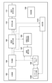
- FIG. 2 is a block diagram showing an example of a functional configuration of an image encoding device.
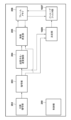
- FIG. 2 is a block diagram showing an example of a functional configuration of an image decoding device.
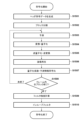
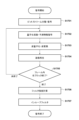
- 5 is a flowchart of encoding processing performed by the image encoding device.
- 5 is a flowchart of decoding processing in the image decoding device.
- FIG. 2 is a block diagram showing an example of the hardware configuration of a computer device. The figure which shows the example of a structure of a bit stream. The figure which shows the example of a structure of a bit stream.
- the figure which shows an example of the method of dividing basic block 700 into subblocks The figure which shows an example of the method of dividing basic block 700 into subblocks. The figure which shows an example of the method of dividing basic block 700 into subblocks. The figure which shows an example of the method of dividing basic block 700 into subblocks. The figure which shows an example of the method of dividing basic block 700 into subblocks. The figure which shows an example of the method of dividing basic block 700 into subblocks. The figure which shows an example of the method of dividing basic block 700 into subblocks. The figure which shows an example of a quantization matrix. The figure which shows an example of a quantization matrix. The figure which shows an example of a quantization matrix. The figure which shows the order of reference of the value of each element in a quantization matrix.
- FIG. 3 is a diagram for explaining intra/inter mixed prediction.
- FIG. 3 is a diagram for explaining intra/inter mixed prediction.
- FIG. 3 is a diagram for explaining intra/inter mixed prediction.
- FIG. 3 is a diagram for explaining intra/inter mixed prediction.
- FIG. 3 is a diagram for explaining intra/inter mixed prediction.
- FIG. 3 is a diagram for explaining intra/inter mixed prediction.
- FIG. 3 is a diagram for explaining intra/inter mixed prediction.
- FIG. 3 is a diagram for explaining intra/inter mixed prediction.
- FIG. 3 is a diagram for explaining intra/inter mixed prediction.
- FIG. 3 is a diagram for explaining intra/inter mixed prediction.
- FIG. 3 is a diagram for explaining intra/inter mixed prediction.
- FIG. 3 is a diagram for explaining intra/inter mixed prediction.
- FIG. 2 is a block diagram showing an example of a functional configuration of an image encoding device.
- FIG. 3 is a diagram illustrating a pixel group at the boundary between a sub-block P and a sub-block Q.
- 5 is a flowchart of encoding processing performed by the image encoding device.
- FIG. 2 is a block diagram showing an example of a functional configuration of an image decoding device.
- 5 is a flowchart of decoding processing in the image decoding device.
- the image encoding device applies an intra-predicted image obtained by intra-prediction to a partial region of a block to be encoded included in an image, and applies an intra-predicted image obtained by intra-prediction to a partial region of the block to be encoded. For the region, a predicted image is obtained by applying the inter-predicted image obtained by inter-prediction.
- the image encoding device then encodes the quantized coefficients obtained by quantizing the orthogonal transform coefficients of the difference between the block and the predicted image using a quantization matrix (first encoding).
- the control unit 150 controls the operation of the entire image encoding device.
- the dividing unit 102 divides the input image into a plurality of basic blocks and outputs each of the divided basic blocks.
- the input image may be an image of each frame constituting a moving image (for example, an image of each frame in a moving image of 30 frames/second), or a still image that is captured regularly or irregularly. There may be.
- the dividing unit 102 may acquire the input image from any device, for example, it may acquire the input image from an imaging device such as a video camera, or it may acquire the input image from a device that holds a plurality of images. Alternatively, the information may be acquired from a memory accessible by the own device.
- the holding unit 103 holds quantization matrices corresponding to each of the plurality of prediction processes.
- the holding unit 103 stores a quantization matrix corresponding to intra prediction which is intra-frame prediction, a quantization matrix corresponding to inter prediction which is inter-frame prediction, and a quantization matrix corresponding to the above-mentioned intra-inter mixed prediction. Assume that the matrix is held.
- each quantization matrix held by the holding unit 103 may be a quantization matrix having default element values, or may be a quantization matrix generated by the control unit 150 in response to a user operation. . Further, each quantization matrix held by the holding unit 103 may be a quantization matrix generated by the control unit 150 according to the characteristics of the input image (the amount of edges, frequency, etc. included in the input image).
- the prediction unit 104 divides each basic block into a plurality of subblocks. Then, the prediction unit 104 obtains a predicted image by intra prediction, inter prediction, or mixed intra/inter prediction for each subblock, and obtains the difference between the subblock and the predicted image as a prediction error.
- the prediction unit 104 also generates information necessary for prediction, such as information indicating a basic block division method, a prediction mode indicating prediction for obtaining a predicted image of a sub-block, and a motion vector, as prediction information.
- the transformation/quantization unit 105 performs orthogonal transformation (frequency transformation) on the prediction error of each subblock obtained by the prediction unit 104 to generate orthogonal transformation coefficients for the subblock, and the prediction unit 104 generates orthogonal transformation coefficients for the subblock.
- the quantization matrix corresponding to the prediction (intra prediction, inter prediction, intra/inter mixed prediction) performed to obtain the predicted image of the sub-block is acquired from the holding unit 103, and the acquired quantization matrix is used to perform the orthogonal prediction.
- quantized coefficients quantization results of the orthogonal transform coefficients
- the inverse quantization/inverse transformation unit 106 converts the quantization coefficients of each sub-block generated by the transformation/quantization unit 105 into a quantization matrix used by the transformation/quantization unit 105 to generate the quantization coefficients.
- the orthogonal transform coefficients are generated by performing inverse quantization of the quantized coefficients using , and the orthogonal transform coefficients are inverse orthogonally transformed to generate (regenerate) a prediction error.
- the image reproduction unit 107 generates a predicted image from the image stored in the frame memory 108 based on the prediction information generated by the prediction unit 104, and combines the predicted image with the image generated by the inverse quantization/inverse transformation unit 106. Regenerate the image from the prediction error.
- the image reproduction unit 107 then stores the reproduced image in the frame memory 108.
- the images stored in the frame memory 108 are referred to by the prediction unit 104 when predicting images of the current frame or the next frame.
- the in-loop filter unit 109 performs in-loop filter processing such as a deblocking filter and sample adaptive offset on the image stored in the frame memory 108.
- the encoding unit 110 encodes the quantized coefficients generated by the conversion/quantization unit 105 and the prediction information generated by the prediction unit 104 to generate encoded data (encoded data).
- the encoding unit 113 encodes the quantization matrix held in the storage unit 103 (including at least the quantization matrix used in quantization by the conversion/quantization unit 105) to generate encoded data (coded data). .
- the integrated encoding unit 111 generates header encoded data using the encoded data generated by the encoding unit 113, and generates bits including the encoded data generated by the encoding unit 110 and the header encoded data. Generate and output a stream.
- the output destination of the bitstream is not limited to a specific output destination.
- the bitstream may be output to the memory of the image encoding device, it may be output to an external device via a network to which the image encoding device is connected, or it may be output for broadcasting. It may also be sent externally.
- the dividing unit 102 divides the input image into a plurality of basic blocks and outputs each of the divided basic blocks.
- the prediction unit 104 divides each basic block into a plurality of subblocks.
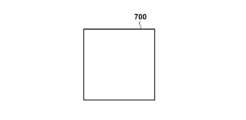
- 7A-7F illustrate an example of how basic block 700 is divided into subblocks.
- FIG. 7B shows an example of conventional square sub-block division, in which a basic block 700 of 8 pixels x 8 pixels is divided into four 4-pixel x 4 pixel sub-blocks (quadtree partitioning).
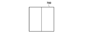
- FIG. 7C to 7F represent examples of types of rectangular subblock division.
- a basic block 700 of 8 pixels x 8 pixels is divided into two sub-blocks of 4 pixels (horizontal direction) x 8 pixels (vertical direction) (binary tree partitioning).
- FIG. 7D the basic block 700 of 8 pixels x 8 pixels is divided into two sub-blocks of 8 pixels (horizontal direction) x 4 pixels (vertical direction) (binary tree partitioning).
- a basic block 700 of 8 pixels x 8 pixels includes a sub-block of 2 pixels (horizontal direction) x 8 pixels (vertical direction), a sub-block of 4 pixels (horizontal direction) x 8 pixels (vertical direction), and a sub-block of 2 pixels (horizontal direction) x 8 pixels (vertical direction). It is divided into three sub-blocks of (horizontal direction) x 8 pixels (vertical direction). That is, in FIG. 7E, the basic block 700 is divided into subblocks with a width (horizontal length) ratio of 1:2:1 (ternary tree division).
- a basic block 700 of 8 pixels x 8 pixels includes a sub-block of 8 pixels (horizontal direction) x 2 pixels (vertical direction), a sub-block of 8 pixels (horizontal direction) x 4 pixels (vertical direction), and a sub-block of 8 pixels (horizontal direction) x 4 pixels (vertical direction). It is divided into three sub-blocks of (horizontal direction) x 2 pixels (vertical direction). That is, in FIG. 7F, the basic block 700 is divided into subblocks at a height (vertical length) ratio of 1:2:1 (ternary tree division).
- encoding processing is performed using not only square sub-blocks but also rectangular sub-blocks.
- prediction information including information indicating such a basic block division method is generated. Note that the division methods shown in FIGS. 7A to 7F are merely examples, and the method of dividing a basic block into subblocks is not limited to the division methods shown in FIGS. 7A to 7F.
- the prediction unit 104 determines the prediction (prediction mode) to be performed for each sub-block.
- the prediction unit 104 then generates a predicted image for each subblock based on the prediction mode determined for the subblock and the encoded pixels, and obtains the difference between the subblock and the predicted image as a prediction error.
- the prediction unit 104 generates "information necessary for prediction" such as information indicating a basic block division method, sub-block prediction mode, motion vector, etc. as prediction information.
- prediction used in this embodiment will be explained again.
- three types of prediction are used: intra prediction, inter prediction, and intra/inter mixed prediction.
- intra prediction In intra prediction (first prediction mode), predicted pixels of the current block to be encoded are generated using encoded pixels located spatially around the current block to be encoded (sub-block in this embodiment).
- encoded pixels in a frame (image) including the block to be encoded are used to generate predicted pixels (predicted image) of the block to be encoded.
- information indicating an intra prediction method such as horizontal prediction, vertical prediction, or DC prediction is generated as "information necessary for prediction.”
- inter prediction In inter prediction (second prediction mode), encoded pixels of another frame (another image) that is different (temporally) from the frame (image) to which the encoding target block (subblock in this embodiment) belongs are used. A predicted pixel of the block to be encoded is generated. For sub-blocks subjected to inter-prediction, motion information indicating reference frames, motion vectors, etc. is generated as "information necessary for prediction.”
- intra-inter mixed prediction third prediction mode
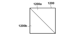
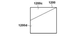
- the block to be coded (sub-block in this embodiment) is divided by diagonal line segments, and the block to be coded is divided into two divided regions. Then, "the predicted pixel obtained for the one divided area by intra prediction for the current block to be encoded” is acquired as the predicted pixel for the one divided area. Further, as the predicted pixel of the other divided area, "the predicted pixel obtained for the other divided area by inter prediction for the current block to be encoded" is acquired.
- the predicted pixels of one divided region of the predicted image obtained by intra-inter mixed prediction for the current block to be encoded are "the predicted pixels obtained for the one divided region by intra prediction for the current block to be encoded.” Furthermore, the predicted pixels of the other divided region of the predicted image obtained by intra-inter mixed prediction for the current block to be encoded are "the predicted pixels obtained for the other divided region by inter prediction for the current block to be encoded.” Examples of dividing a block to be coded in intra-inter mixed prediction are shown in FIGS. 12A to 12H.
- the encoding target block 1200 is divided by a line segment passing through the upper left corner vertex and the lower right corner vertex of the encoding target block 1200, and the encoding target block 1200 is divided into a divided region 1200a and a divided region 1200b.
- Intra/inter mixed prediction processing for the encoding target block 1200 by the prediction unit 104 in this case will be described with reference to FIGS. 12A to 12D.
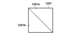
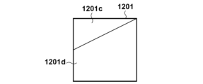
- the prediction unit 104 generates an intra-predicted image 1201 (FIG. 12B) by performing intra-prediction on the encoding target block 1200.
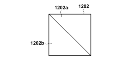
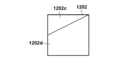
- the intra predicted image 1201 includes an area 1201a located at the same position as the divided area 1200a, and an area 1201b located at the same position as the divided area 1200b. Then, the prediction unit 104 sets the intra-predicted pixels belonging to the region 1201a located at the same position as the divided region 1200a, among the pixels (intra-predicted pixels) included in the intra-predicted image 1201, as "predicted pixels of the divided region 1200a.” Further, by performing inter prediction on the block to be encoded 1200, an inter predicted image 1202 (FIG. 12C) is generated.
- the inter predicted image 1202 includes an area 1202a located at the same position as the divided area 1200a, and an area 1202b located at the same position as the divided area 1200b.
- the prediction unit 104 sets the inter-predicted pixels belonging to the area 1202b located at the same position as the divided area 1200b among the pixels (inter-predicted pixels) included in the inter-predicted image 1202 as "predicted pixels of the divided area 1200b.”
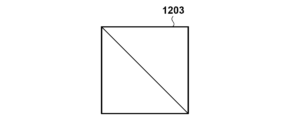
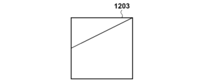
- the prediction unit 104 makes a prediction consisting of an intra prediction pixel included in the area 1201a, which is the "prediction pixel of the divided area 1200a", and an inter prediction pixel included in the area 1202b, which is the "prediction pixel of the divided area 1200b".
- Image 1203 (FIG. 12D) is generated.
- the prediction unit 104 generates the intra-predicted image 1201 (FIG. 12B) by intra-prediction on the block to be coded 1200, and further generates the inter-predicted image 1202 (FIG. 12C) by inter-prediction on the block to be coded 1200. generate. Then, among the intra-predicted pixels in the intra-predicted image 1201, the prediction unit 104 converts the intra-predicted pixel at the position of the coordinates (x, y) included in the area 1201a corresponding to the divided area 1200a into the same intra-predicted pixel in the predicted image 1203. Place at coordinates (x, y).
- the prediction unit 104 selects an inter-predicted pixel at the position of coordinates (x, y) included in the area 1202b corresponding to the divided area 1200b among the inter-predicted pixels in the inter-predicted image 1202, from the same inter-predicted pixel in the predicted image 1203. Place at coordinates (x, y). By doing so, a predicted image 1203 shown in FIG. 12D is generated.
- the intra/inter mixed prediction processing performed by the prediction unit 104 on the current block 1200 to be encoded will be described.
- the encoding target block 1200 is divided by a line segment passing through the midpoint between the upper left corner vertex and the lower left corner vertex and the upper right corner vertex of the encoding target block 1200.
- the prediction unit 104 generates an intra-predicted image 1201 (FIG. 12F) by performing intra-prediction on the encoding target block 1200.
- the intra predicted image 1201 includes an area 1201c located at the same position as the divided area 1200c, and an area 1201d located at the same position as the divided area 1200d. Then, the prediction unit 104 sets the intra-predicted pixels belonging to the region 1201c located at the same position as the divided region 1200c, among the pixels (intra-predicted pixels) included in the intra-predicted image 1201, as "predicted pixels of the divided region 1200c.” Furthermore, the prediction unit 104 generates an inter-predicted image 1202 (FIG. 12G) by performing inter-prediction on the encoding target block 1200.
- FIG. 12G inter-predicted image 1202
- the inter predicted image 1202 includes an area 1202c located at the same position as the divided area 1200c, and an area 1202d located at the same position as the divided area 1200d. Then, the prediction unit 104 sets the inter-predicted pixels belonging to the area 1202d located at the same position as the divided area 1200d among the pixels (inter-predicted pixels) included in the inter-predicted image 1202 as "predicted pixels of the divided area 1200d.” The prediction unit 104 then predicts the intra-predicted pixels included in the region 1201c, which are "predicted pixels of the divided region 1200c," and the inter-predicted pixels included in the region 1202d, which are "predicted pixels of the divided region 1200d.” Image 1203 (FIG. 12H) is generated.
- the prediction unit 104 generates the intra-predicted image 1201 (FIG. 12F) by intra-prediction on the block to be coded 1200, and further generates the inter-predicted image 1202 (FIG. 12G) by inter-prediction on the block to be coded 1200. generate.
- the prediction unit 104 selects an intra-predicted pixel located at the coordinates (x, y) included in the area 1201c corresponding to the divided area 1200c, among the intra-predicted pixels in the intra-predicted image 1201, from the same intra-predicted pixel in the predicted image 1203. Place at coordinates (x, y).
- the prediction unit 104 selects an inter-predicted pixel located at the coordinates (x, y) included in the area 1202d corresponding to the divided area 1200d, among the inter-predicted pixels in the inter-predicted image 1202, from the same inter-predicted pixel in the predicted image 1203. Place at coordinates (x, y). By doing the above, the predicted image 1203 shown in FIG. 12D is generated.
- information indicating the intra prediction method For sub-blocks subjected to intra-inter mixed prediction, information indicating the intra prediction method, motion information indicating the reference frame and motion vector, information specifying the divided area (for example, information specifying the line segment mentioned above) ), etc. are generated as "information necessary for prediction".
- the prediction unit 104 determines the prediction mode of the subblock of interest using the following process.
- the prediction unit 104 generates a difference image between the predicted image generated by intra prediction for the subblock of interest and the subblock of interest.
- the prediction unit 104 also generates a difference image between the predicted image generated by inter prediction for the subblock of interest and the subblock of interest.
- the prediction unit 104 also generates a difference image between the predicted image generated by intra/inter mixed prediction for the subblock of interest and the subblock of interest.
- the pixel value at the pixel position (x, y) in the difference image C between image A and image B is the pixel value AA at the pixel position (x, y) in the image A and the pixel position (x, y) in the image B.
- the prediction unit 104 identifies a predicted image with the smallest total pixel value of all pixels in the difference image, and calculates the prediction made for the sub-block of interest to obtain the predicted image as "of the sub-block of interest". "Prediction mode" is determined. Note that the method for determining the prediction mode of the subblock of interest is not limited to the above method.
- the prediction unit 104 For each subblock, the prediction unit 104 sets the predicted image generated in the prediction mode determined for the subblock as the "predicted image of the subblock," and generates a prediction error from the subblock and the predicted image. The prediction unit 104 also generates prediction information for each subblock, including the prediction mode determined for the subblock and "information necessary for prediction" generated for the subblock.
- the transform/quantization unit 105 generates orthogonal transform coefficients by performing orthogonal transform processing corresponding to the size of the prediction error on the prediction error of the subblock for each subblock. Then, for each sub-block, the conversion/quantization unit 105 obtains a quantization matrix corresponding to the prediction mode of the sub-block from among the quantization matrices held by the holding unit 103, and uses the obtained quantization matrix to The orthogonal transform coefficients of the sub-block are quantized to generate quantized coefficients.
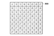
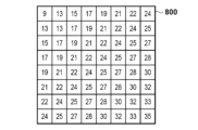
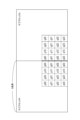
- the holding unit 103 uses the 8 elements x 8 elements illustrated in FIG. It is assumed that a quantization matrix of (all 64 element values are quantization step values) is held. For example, as a quantization matrix used for quantizing the orthogonal transform coefficient of the prediction error obtained when the holding unit 103 performs inter prediction on a subblock of 8 pixels x 8 pixels, an 8 element x 8 It is assumed that a quantization matrix of elements (all 64 element values are quantization step values) is held.
- FIG. 8C illustrates a quantization matrix used to quantize orthogonal transform coefficients of prediction errors obtained when the holding unit 103 performs intra-inter mixed prediction on a subblock of 8 pixels x 8 pixels. It is assumed that a quantization matrix of 8 elements x 8 elements (the values of the 64 elements are all quantization step values) is held.
- the transform/quantization unit 105 quantizes the orthogonal transform coefficient of "prediction error obtained by intra prediction for an 8 pixel x 8 pixel subblock" using the quantization matrix for intra prediction in FIG. 8A. .
- the transform/quantization unit 105 quantizes the orthogonal transform coefficient of "the prediction error obtained by inter prediction for the 8 pixel x 8 pixel subblock" using the quantization matrix for inter prediction in FIG. 8B.
- the transform/quantization unit 105 uses the quantization matrix for intra/inter mixed prediction of FIG. and quantize it.
- the inverse quantization/inverse transformation unit 106 converts the quantization coefficient of each sub-block generated by the transformation/quantization unit 105 into a quantization matrix used by the transformation/quantization unit 105 in quantizing the sub-block.
- Orthogonal transform coefficients are generated by performing inverse quantization using , and a prediction error is generated (regenerated) by performing inverse orthogonal transform on the orthogonal transform coefficients.
- the image reproduction unit 107 generates a predicted image from the image stored in the frame memory 108 based on the prediction information generated by the prediction unit 104, and combines the predicted image with the image generated by the inverse quantization/inverse transformation unit 106 (The sub-block image is reproduced by adding the predicted error (reproduced) and the predicted error. The image reproduction unit 107 then stores the reproduced image in the frame memory 108.
- the in-loop filter unit 109 performs in-loop filter processing such as a deblocking filter and sample adaptive offset on the image stored in the frame memory 108, and stores the in-loop filter-processed image in the frame memory 108. .
- the encoding unit 110 For each subblock, the encoding unit 110 entropy encodes the quantization coefficient of the subblock generated by the transform/quantization unit 105 and the prediction information of the subblock generated by the prediction unit 104. Generate encoded data. Note that the entropy encoding method is not particularly specified, but Golomb encoding, arithmetic encoding, Huffman encoding, etc. can be used.
- the quantization matrix held by the holding unit 103 is generated according to the size of the sub-block to be encoded and the prediction mode. For example, as shown in FIGS. 7A to 7F, the sizes of the sub-blocks to be divided are 8 pixels x 8 pixels, 4 pixels x 4 pixels, 8 pixels x 4 pixels, 4 pixels x 8 pixels, 8 pixels x 2 pixels, 2 pixels x 8 pixels, etc.
- the quantization matrix of the adopted size is registered in the holding unit 103.
- a quantization matrix is prepared for each of intra prediction, inter prediction, and intra/inter mixed prediction, and is registered in the holding unit 103.
- the method of generating a quantization matrix according to the sub-block size and prediction mode is not limited to the specific generation method as described above, and the method of managing such a quantization matrix in the storage unit 103 may also be specified. It is not limited to the management method.
- the quantization matrix held by the holding unit 103 is held in a two-dimensional shape as shown in FIGS. 8A to 8C, but each element in the quantization matrix is not limited to this. It is also possible to hold a plurality of quantization matrices for the same prediction method depending on the size of the subblock or whether the encoding target is a luminance block or a chrominance block.
- the quantization matrix realizes quantization processing according to human visual characteristics, so the element for the DC component corresponding to the upper left corner of the quantization matrix is small, as shown in Figures 8A to 8C.
- the AC component element corresponding to the lower part is large.
- the encoding unit 113 reads out the quantization matrix held in the holding unit 103 (including at least the quantization matrix used in quantization by the conversion/quantization unit 105), and encodes the read quantization matrix. For example, the encoding unit 113 encodes the quantization matrix of interest using the following process.
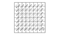
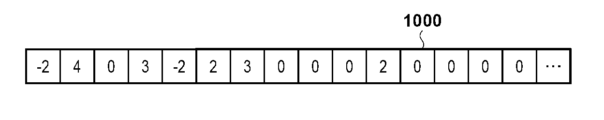
- the encoding unit 113 refers to the values of each element in the quantization matrix of interest, which is a two-dimensional array, in a prescribed order, and arranges the difference values between the currently referenced element value and the immediately previously referenced element value. Create a one-dimensional array. For example, when the quantization matrix in FIG. 8C is the quantization matrix of interest, the encoding unit 113 converts the value of the element in the upper left corner of the quantization matrix of interest to the value of the element in the lower right corner of the quantization matrix of interest, as shown in FIG. Refer to the values of each element in the order indicated by the arrows.
- the encoding unit 113 uses a predetermined value or a value determined by some method as the output value. Output. For example, the encoding unit 113 may output the value "8" of the currently referenced element as the output value, or may output the value obtained by subtracting the specified value from the value "8" of the element as the output value. Alternatively, the output value does not have to be determined by a specific method.
- the value of the next referenced element is "11" and the value of the immediately previous referenced element is "8", so the encoding unit 113 converts the currently referenced element from the value "11" to the previous reference.
- the difference value "+3" obtained by subtracting the value "8" of the element is output as the output value.
- the encoding unit 113 refers to the values of each element in the quantization matrix in a prescribed order, obtains and outputs an output value, and generates a one-dimensional array in which the output values are arranged in the output order.
- FIG. 10A A one-dimensional array generated from the quantization matrix of FIG. 8A through such processing is shown in FIG. 10A.
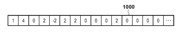
- FIG. 10B shows a one-dimensional array generated from the quantization matrix of FIG. 8B by such processing.
- FIG. 10C shows a one-dimensional array generated from the quantization matrix of FIG. 8C by such processing.
- FIGS. 10A to 10C it is assumed that "8" is set as the above specified value.
- the encoding unit 113 encodes the one-dimensional array generated for the quantization matrix of interest.
- the encoding unit 113 refers to the encoding table illustrated in FIG. 11A and generates, as encoded data, a bit string in which each element value in the one-dimensional array is replaced with a corresponding binary code.
- the encoding table is not limited to the encoding table shown in FIG. 11A, and for example, the encoding table illustrated in FIG. 11B may be used.
- the integrated encoding unit 111 integrates "header information necessary for image encoding" into the encoded data generated by the encoding unit 113, and generates encoded data with the header information integrated. to generate header code data. Then, the integrated encoding unit 111 generates and outputs a bitstream in which the encoded data generated by the encoding unit 110 and the header code data are multiplexed.
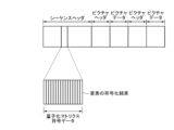
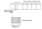
- FIG. 6A shows a configuration example of a bitstream generated by the integrated encoding unit 111.
- the sequence header includes coded data of the quantization matrix, and includes coded data of each element.
- the encoded position is not limited to this, and a configuration in which the encoded information is encoded in a picture header or other header may be adopted.
- step S302 the encoding unit 113 reads out the quantization matrix held in the holding unit 103 (including at least the quantization matrix used by the conversion/quantization unit 105 in quantization), and converts the read quantization matrix into Encode to generate encoded data.
- step S303 the integrated encoding unit 111 generates "header information necessary for image encoding". Then, the integrated encoding unit 111 integrates "header information necessary for image encoding" into the encoded data generated by the encoding unit 113 in step S302, and uses the encoded data with the integrated header information. Generate header code data.
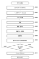
- step S304 the dividing unit 102 divides the input image into a plurality of basic blocks, and outputs each of the divided basic blocks.
- the prediction unit 104 then divides each basic block into a plurality of subblocks.
- step S306 the transform/quantization unit 105 generates orthogonal transform coefficients by performing orthogonal transform processing corresponding to the size of the prediction error on the prediction error of the selected sub-block obtained in step S305. Then, the conversion/quantization unit 105 obtains a quantization matrix corresponding to the prediction mode of the selected sub-block from among the quantization matrices held by the holding unit 103, and uses the obtained quantization matrix to transform the sub-block. Quantize the orthogonal transform coefficients to obtain quantized coefficients.
- step S307 the inverse quantization/inverse transformation unit 106 uses the quantization matrix that the transformation/quantization unit 105 used in quantization for the selected subblock for the quantization coefficient of the selected subblock acquired in step S306. Orthogonal transform coefficients are generated by performing inverse quantization. Then, the inverse quantization/inverse transform unit 106 performs inverse orthogonal transform on the generated orthogonal transform coefficients to generate (regenerate) a prediction error.
- step S308 the image reproduction unit 107 generates a predicted image from the image stored in the frame memory 108 based on the prediction information acquired in step S305, and adds the predicted image and the prediction error generated in step S307. to play the sub-block image.
- the image reproduction unit 107 then stores the reproduced image in the frame memory 108.
- step S309 the encoding unit 110 generates encoded data by entropy encoding the quantized coefficients acquired in step S306 and the prediction information acquired in step S305.
- step S310 the control unit 150 determines whether all sub-blocks in the input image have been selected as selected sub-blocks. As a result of this determination, if all subblocks in the input image are selected as selected subblocks, the process advances to step S311. On the other hand, if one or more subblocks that have not yet been selected as selected subblocks remain among the subblocks in the input image, the process proceeds to step S305.
- step S311 the in-loop filter unit 109 performs in-loop filter processing on the image stored in the frame memory 108 (the image of the selected sub-block reproduced in step S308).
- the in-loop filter unit 109 then stores the in-loop filter-processed image in the frame memory 108.
- the orthogonal transform coefficients of sub-blocks that have been subjected to intra-inter mixed prediction can be quantized using a quantization matrix that supports intra-inter mixed prediction, so quantization is performed for each frequency component. control and improve image quality.
- quantization matrices are individually prepared for each of intra prediction, inter prediction, and intra/inter mixed prediction, and the quantization matrices corresponding to each prediction are encoded. However, some of them may be made common.
- a quantization matrix corresponding to intra-prediction may be used instead of a quantization matrix corresponding to intra-inter-mixed prediction.
- the quantization matrix for intra-prediction in FIG. 8A is used instead of the quantization matrix for intra-inter mixed prediction in FIG. 8C.
- a quantization matrix may also be used. In this case, encoding of the quantization matrix corresponding to intra-inter mixed prediction can be omitted. As a result, it is possible to reduce the amount of encoded data of the quantization matrix included in the bitstream, and it is also possible to reduce image quality deterioration caused by intra-prediction errors such as block distortion.
- a quantization matrix corresponding to inter prediction instead of a quantization matrix corresponding to intra/inter mixed prediction to quantize the orthogonal transform coefficients of the prediction error obtained based on intra/inter mixed prediction.
- the quantization matrix for inter prediction in FIG. 8B is used instead of the quantization matrix for intra/inter mixed prediction in FIG. 8C.
- a quantization matrix may also be used. In this case, encoding of the quantization matrix corresponding to intra-inter mixed prediction can be omitted. Thereby, it is possible to reduce the amount of encoded data of the quantization matrix included in the bitstream, and it is also possible to reduce image quality deterioration caused by errors due to inter prediction such as jerky motion.
- the size of the area of ⁇ predicted pixels obtained by intra prediction'' and the area of ⁇ predicted pixels obtained by inter prediction'' is Accordingly, a quantization matrix to be used for the sub-block may be determined.
- the transform/quantization unit 105 performs orthogonal transformation of sub-block 1200.
- a quantization matrix for example, the quantization matrix in FIG. 8A
- intra prediction is applied to quantize the coefficients.
- a quantization matrix obtained by combining a "quantization matrix corresponding to intra prediction" and "a quantization matrix corresponding to inter prediction” according to the ratio of S1 and S2 is quantized to correspond to intra-inter mixed prediction. It may also be generated as a matrix.
- the conversion/quantization unit 105 may generate a quantization matrix corresponding to intra/inter mixed prediction using the following equation (1).
- the quantization matrix applied to the sub-block to which intra-inter mixed prediction is applied is configured to be uniquely determined, but it may be configured to be selectable by introducing an identifier.
- the quantization matrix to be applied to the sub-block to which intra-inter mixed prediction is applied select from among the following: quantization matrix compatible with intra prediction, quantization matrix compatible with inter prediction, quantization matrix compatible with intra-inter mixed prediction There are various ways to do this.
- the control unit 150 may select according to a user operation.
- the bitstream stores an identifier for specifying the quantization matrix selected as the quantization matrix to be applied to the sub-block to which intra-inter mixed prediction is applied.
- a quantization matrix encoding method information code is newly introduced as the above-mentioned identifier, thereby selectively applying the quantization matrix to the sub-block to which intra-inter mixed prediction is applied.
- the quantization matrix encoding method information code indicates 0, it indicates that a quantization matrix corresponding to intra prediction has been applied to a subblock to which intra/inter mixed prediction has been applied.
- the quantization matrix encoding method information code indicates 1, it indicates that a quantization matrix corresponding to inter prediction has been applied to a subblock to which intra/inter mixed prediction has been applied.
- the quantization matrix encoding method information code indicates 2
- the predicted pixel value of the corresponding area corresponding to one of the divided areas in the predicted image becomes the first predicted pixel
- the predicted pixel value of the corresponding area corresponding to the other divided area in the predicted image becomes the second predicted pixel.
- the predicted pixel value of the corresponding area corresponding to the above boundary area becomes the third predicted pixel.
- intra-inter composite prediction (CIIP) adopted in VVC may be used.
- Intra/inter composite prediction is prediction in which pixels of the entire block to be encoded are calculated by a weighted average of predicted pixels by intra prediction and predicted pixels by inter prediction.
- the quantization matrix used for sub-blocks using intra-inter mixed prediction and the quantization matrix used for sub-blocks using intra-inter combined prediction can be made common. .
- quantization control with the same quantization control properties is applied. Quantization using a quantization matrix can be applied. Furthermore, it is also possible to reduce the amount of code for the quantization matrix corresponding to the new prediction method.
- the encoding target is the input image, but the encoding target is not limited to images.
- a configuration may be adopted in which a two-dimensional data array, which is feature data used in machine learning such as object recognition, is encoded in the same way as an input image to generate and output a bit stream. This makes it possible to efficiently encode feature data used in machine learning.
- the image decoding device decodes quantized coefficients for a block to be decoded from a bitstream, derives transform coefficients from the quantized coefficients using a quantization matrix, and inverts the transform coefficients. By performing frequency conversion, a prediction error for the block to be decoded is derived. Then, the image decoding device applies the intra-predicted image obtained by intra prediction to a part of the area in the block to be decoded, and uses inter prediction to apply the intra-predicted image obtained by intra prediction to another area different from the part of area in the block to be decoded. A predicted image is generated by applying the obtained inter-predicted image, and a block to be decoded is decoded using the generated predicted image and the prediction error.
- an image decoding device that decodes a bitstream encoded by the image encoding device according to the first embodiment will be described.
- an example of the functional configuration of the image decoding device according to the present embodiment will be described using the block diagram of FIG. 2.
- the separation/decoding section 202 separates the encoded data of the quantization matrix from the bitstream and supplies the encoded data to the decoding section 209 . Furthermore, the separation/decoding unit 202 separates the encoded data of the input image from the bitstream and supplies the encoded data to the decoding unit 203 . In other words, the separation decoding section 202 performs an operation opposite to that of the integrated encoding section 111 in FIG.
- the decoding unit 209 decodes the encoded data supplied from the separation decoding unit 202 and reproduces the quantization matrix.
- Decoding section 203 decodes the encoded data supplied from separation decoding section 202 and reproduces quantized coefficients and prediction information.
- the inverse quantization/inverse transform unit 204 performs the same operation as the inverse quantization/inverse transform unit 106 included in the image encoding device according to the first embodiment.
- the inverse quantization/inverse transform unit 204 selects a quantization matrix corresponding to the prediction corresponding to the quantization coefficient to be decoded from among the quantization matrices decoded by the decoding unit 209, and uses the selected quantization matrix to The quantized coefficients are dequantized to reproduce orthogonal transform coefficients. Then, the inverse quantization/inverse transform unit 204 performs inverse orthogonal transform on the reproduced orthogonal transform coefficients to reproduce the prediction error.
- the in-loop filter unit 207 performs in-loop filter processing such as a deblocking filter and sample adaptive offset on the reproduced image stored in the frame memory 206.
- the reproduced image stored in the frame memory 206 is outputted by the control unit 250 as appropriate.
- the output destination of the reproduced image is not limited to a specific output destination.
- the reproduced image may be displayed on the display screen of a display device such as a display, or the reproduced image may be output to a projection device such as a projector. Also good.
- the separation/decoding unit 202 acquires the bitstream generated by the image encoding device, separates information related to decoding processing and encoded data regarding coefficients from the bitstream, and decodes the encoded data present in the header of the bitstream. do. Separation and decoding section 202 extracts encoded data of the quantization matrix from the sequence header of the bitstream in FIG. 6A, and supplies the extracted encoded data to decoding section 209. Separation decoding section 202 also supplies encoded data of picture data in units of subblocks to decoding section 203 .
- the decoding unit 209 decodes the encoded data of the quantization matrix supplied from the separation decoding unit 202 to reproduce a one-dimensional array. More specifically, the decoding unit 209 generates a one-dimensional array in which the binary codes in the encoded data of the quantization matrix are decoded into difference values with reference to the encoding tables illustrated in FIGS. 11A and 11B. do. For example, when the decoding unit 209 decodes the encoded data of the quantization matrices of FIGS. 8A to 8C, the one-dimensional arrays of FIGS. 10A to 10C are respectively reproduced.
- decoding is performed using the encoding table shown in FIG. 11A (or FIG. 11B), but the encoding table is not limited to this, and the encoding table shown in FIG. Other encoding tables may be used as long as they use the same format.
- the value obtained by adding the value of the second element from the head of the one-dimensional array to the value of the element at the head of the one-dimensional array becomes the second element value in the above-mentioned "specified order."
- the value obtained by adding the value of the nth element from the beginning of the one-dimensional array (2 ⁇ n ⁇ N: N is the number of elements in the one-dimensional array) to the value of the (n-1)th element from the beginning of the one-dimensional array. becomes the nth element value in the above "prescribed order".
- the decoding unit 209 reproduces the quantization matrices of FIGS. 8A to 8C from the one-dimensional arrays of FIGS. 10A to 10C using the order shown in FIG. 9, respectively.
- the inverse quantization/inverse transformation unit 204 identifies the “prediction mode corresponding to the quantization coefficient to be decoded” included in the prediction information decoded by the decoding unit 203, and converts the quantization matrix reproduced by the decoding unit 209 into Among them, a quantization matrix corresponding to the specified prediction mode is selected. Then, the inverse quantization/inverse transform unit 204 inversely quantizes the quantized coefficients using the selected quantization matrix to reproduce orthogonal transform coefficients. Then, the inverse quantization/inverse transform unit 204 reproduces the prediction error by performing inverse orthogonal transform on the reproduced orthogonal transform coefficients, and supplies the reproduced prediction error to the image reproduction unit 205.
- the image reproduction unit 205 generates a predicted image by referring to the image stored in the frame memory 206 based on the prediction information decoded by the decoding unit 203.
- three types of prediction are used: intra prediction, inter prediction, and intra/inter mixed prediction.
- the specific prediction process is the same as that of the prediction unit 104 described in the first embodiment, so the description will be omitted.
- the image reproduction unit 205 generates a reproduced image by adding the prediction error obtained by the inverse quantization/inverse transformation unit 204 to the generated predicted image, and stores the generated reproduced image in the frame memory 206. Store.
- the reproduced image stored in the frame memory 206 becomes a predictive reference candidate to be referred to when decoding other sub-blocks.
- the in-loop filter unit 207 operates in the same manner as the in-loop filter unit 109 described above, and performs in-loop filter processing such as a deblocking filter and sample adaptive offset on the reproduced image stored in the frame memory 206.
- the reproduced image stored in the frame memory 206 is outputted by the control unit 250 as appropriate.
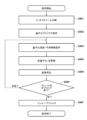
- step S401 the separation decoding unit 202 obtains an encoded bitstream. Then, the separation/decoding unit 202 separates the encoded data of the quantization matrix from the obtained bitstream, and supplies the encoded data to the decoding unit 209 . Furthermore, the separation/decoding unit 202 separates the encoded data of the input image from the bitstream and supplies the encoded data to the decoding unit 203 .
- step S402 the decoding unit 209 decodes the encoded data supplied from the separation decoding unit 202 and reproduces the quantization matrix.
- step S403 the decoding unit 203 decodes the encoded data supplied from the separation decoding unit 202, and reproduces the quantization coefficient and prediction information of the sub-block to be decoded.
- step S405 the image reproduction unit 205 generates a predicted image of the sub-block to be decoded by referring to the image stored in the frame memory 206 based on the prediction information decoded by the decoding unit 203. Then, the image reproduction unit 205 adds the prediction error of the sub-block to be decoded obtained by the inverse quantization/inverse transformation unit 204 to the generated predicted image, thereby generating a reproduced image of the sub-block to be decoded.
- the generated playback image is stored in the frame memory 206.
- step S406 the control unit 250 determines whether the processes of steps S403 to S405 have been performed for all sub-blocks. As a result of this determination, if steps S403 to S405 have been performed for all sub-blocks, the process proceeds to step S407. On the other hand, if there are still subblocks that have not been processed in steps S403 to S405, the process proceeds to step S403 to perform the processes in steps S403 to S405 for the subblocks.
- step S407 the in-loop filter unit 207 performs in-loop filter processing such as a deblocking filter and sample adaptive offset on the reproduced image generated in step S405 and stored in the frame memory 206.
- in-loop filter processing such as a deblocking filter and sample adaptive offset on the reproduced image generated in step S405 and stored in the frame memory 206.
- quantization is controlled for each frequency component to decode a bitstream with improved image quality. be able to.
- quantization matrices were prepared individually for each of intra prediction, inter prediction, and intra/inter mixed prediction, and the quantization matrices corresponding to each prediction were decoded. However, some of them may be made common.
- the quantization matrix corresponding to the inter prediction is used instead of the quantization matrix corresponding to the intra-inter mixed prediction.
- the quantization matrix may be decoded and used. That is, for example, in order to dequantize the quantization coefficient of the orthogonal transform coefficient of the prediction error obtained based on the intra-inter mixed prediction, the quantization matrix for inter prediction shown in FIG. 8B may be used. In this case, decoding of the quantization matrix corresponding to intra-inter mixed prediction can be omitted.
- the corresponding A quantization matrix used for inverse quantization of sub-blocks may be determined.
- the inverse quantization/inverse transform unit 204 A quantization matrix corresponding to intra prediction is applied to inverse quantization of the quantization coefficients.
- the quantization matrix applied to the sub-block to which intra-inter mixed prediction is applied is configured to be uniquely determined, but as in the first embodiment, it can be selected by introducing an identifier. A configuration may also be used. As a result, it is possible to decode a bitstream that selectively achieves a reduction in the amount of encoded data of the quantization matrix included in the bitstream and unique quantization control for subblocks that apply intra/inter mixed prediction. I can do it.
- a predicted image including a predicted pixel for one divided region (first predicted pixel) into which a sub-block is divided and a predicted pixel for the other divided region (second predicted pixel) is decoded.
- the predicted image to be decoded is not limited to such a predicted image.
- calculation is performed by a weighted average of the first predicted pixel and the second predicted pixel included in the area near the boundary (boundary area) between one divided area and the other divided area.
- the predicted image may be a predicted image in which the third predicted pixel thus obtained is the predicted pixel of the boundary area.
- the predicted image to be decoded is similar to the first embodiment, the predicted pixel value of the corresponding area corresponding to one of the above divided areas in the predicted image is the first predicted pixel, and the predicted pixel value of the corresponding area corresponding to the above one divided area in the predicted image is the first predicted pixel, and The predicted pixel value of the corresponding area corresponding to becomes the second predicted pixel. Then, in the predicted image, the predicted pixel value of the corresponding area corresponding to the above boundary area becomes the third predicted pixel. As a result, it is possible to suppress deterioration in image quality in the boundary areas of divided areas in which different predictions are used, and to enable decoding of a bitstream with improved image quality.
- intra-inter composite prediction adopted in VVC may be used.
- the quantization matrix used for sub-blocks using intra-inter mixed prediction and the quantization matrix used for sub-blocks using intra-inter combined prediction can be made common.
- sub-blocks that use prediction methods that have the same feature of using both intra-prediction predicted pixels and inter-prediction predicted pixels within the same sub-block have the same quantization control properties. It is possible to enable decoding of a bitstream to which quantization using a quantization matrix is applied. Furthermore, it is also possible to decode a bitstream in which the amount of code is reduced by a quantization matrix corresponding to a new prediction method.
- the input image to be encoded is decoded from the bitstream, but the decoding target is not limited to images.
- the decoding target is not limited to images.
- the image encoding device performs prediction processing on an image block by block and encodes the image.
- the image encoding device determines the strength of deblocking filter processing to be performed on the boundary between a first block in the image and a second block adjacent to the first block in the image, and A corresponding deblocking filter process is performed on the boundary.
- the prediction process includes a first prediction mode (intra prediction) that uses pixels in an image including the block to be coded to derive predicted pixels of the block to be coded, and an image including the block to be coded.
- the transform/quantization unit 105 uses a predetermined quantization matrix when quantizing orthogonal transform coefficients; - A quantization matrix compatible with inter mixed prediction may be used.
- the in-loop filter unit 1309 performs in-loop filter processing such as a deblocking filter on the image (sub-block) stored in the frame memory 108 according to the filter strength (bS value) determined by the determining unit 1313. conduct.
- the in-loop filter unit 1309 then stores the in-loop filter-processed image in the frame memory 108.
- the bS value is set to 1 (Condition 4) If sub-block P and sub-block Q have different reference images for motion compensation or different numbers of motion vectors, Set the bS value to 1 (Condition 5) If the absolute value of the difference between the motion vector in sub-block P and the motion vector in sub-block Q is 0.5 pixels or more, set the bS value to 1 (Condition 6) In cases other than (Condition 1) to (Condition 5), the bS value is set to 0.
- deblocking filter processing is not performed for sub-block boundaries (edges) where the bS value is 0, and the bS value is 1.
- a deblocking filter is determined based on the gradient and activity near the sub-block boundaries. Basically, the larger the bS value, the stronger the deblocking filter processing is performed.
- the bS value is used as the filter strength, but the invention is not limited to this.
- other variables than the bS value may be defined as the filter strength, or the coefficients and filter length of the deblocking filter may be directly changed.
- Subblock P and subblock Q in FIG. 14 are 8 ⁇ 8 pixel subblocks that are adjacent to each other across the boundary, and are also the unit of orthogonal transformation.
- p00 to p33 indicate pixels (pixel values) belonging to sub-block P
- q00 to q33 indicate pixels (pixel values) belonging to sub-block Q
- the pixel group p00 to p33 and the pixel group q00 to q33 have a boundary. They are in contact with each other.
- the in-loop filter unit 1309 determines whether to perform deblocking filter processing on the boundary between sub-block P and sub-block Q, for example, according to the following equation. do.
- the integrated encoding unit 111 generates a bitstream by multiplexing the header code data generated in step S1501 and the encoded data generated by the encoding unit 110 in step S1507.
- step S1508 the control unit 150 determines whether all sub-blocks in the input image have been selected as selected sub-blocks. As a result of this determination, if all subblocks in the input image are selected as selected subblocks, the process advances to step S1509. On the other hand, if one or more subblocks that have not yet been selected as selected subblocks remain among the subblocks in the input image, the process advances to step S1503.
- an image decoding device that decodes a bitstream encoded by an image encoding device according to the third embodiment will be described.
- an example of the functional configuration of the image decoding device according to this embodiment will be described using the block diagram of FIG. 16.
- FIG. 16 the same reference numerals are given to the same functional parts as those shown in FIG. 2, and the description of the functional parts will be omitted.
- the bS value is used to determine whether to apply a deblocking filter and to calculate the maximum amount of pixel value correction by the deblocking filter.
- a strong filter with a high smoothing effect and a weak filter with a weak smoothing effect were used depending on the pixel value conditions.
- the filter length may be determined according to the bS value, or only the strength of the smoothing effect may be determined based on the bS value.
- step S1701 the separation decoding unit 202 obtains a bitstream.
- the separation/decoding unit 202 separates the encoded data of the input image from the bitstream, supplies the encoded data to the decoding unit 203, and decodes the header encoded data in the bitstream.
- step S1705 the control unit 250 determines whether the processes of steps S1702 to S1704 have been performed for all sub-blocks. As a result of this determination, if steps S1702 to S174 have been performed for all sub-blocks, the process advances to step S1706. On the other hand, if there are still subblocks that have not been processed in steps S1702 to S1704, the process advances to step S1702 to perform the processes in steps S1702 to S1704 for the subblocks.
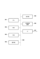
- the RAM 502 has an area for storing computer programs and data loaded from an external storage device 506, and an area for storing data acquired from the outside via an I/F (interface) 507. Furthermore, the RAM 502 has a work area (such as a frame memory) used when the CPU 501 executes various processes. In this way, the RAM 502 can provide various areas as appropriate.
- a work area such as a frame memory
- Computer programs and data stored in the external storage device 506 are loaded into the RAM 502 as appropriate under the control of the CPU 501 and are subject to processing by the CPU 501.
- the above-described holding unit 103 and frame memories 108 and 206 can be implemented using the RAM 502, ROM 503, external storage device 506, and the like.
Landscapes
- Engineering & Computer Science (AREA)
- Multimedia (AREA)
- Signal Processing (AREA)
- Compression Or Coding Systems Of Tv Signals (AREA)
Priority Applications (4)
| Application Number | Priority Date | Filing Date | Title |
|---|---|---|---|
| EP23774208.5A EP4498673A1 (en) | 2022-03-22 | 2023-01-18 | Image encoder, image decoder, image encoding method and image decoding method |
| CN202380028369.0A CN118891872A (zh) | 2022-03-22 | 2023-01-18 | 图像编码设备、图像解码设备、图像编码方法和图像解码方法 |
| KR1020247034070A KR20240166515A (ko) | 2022-03-22 | 2023-01-18 | 화상 부호화 장치, 화상 복호 장치, 화상 부호화 방법, 및 화상 복호 방법 |
| US18/809,569 US20240414335A1 (en) | 2022-03-22 | 2024-08-20 | Image encoding apparatus, image decoding apparatus, image encoding method, image decoding method, and non-transitory computer-readable storage medium |
Applications Claiming Priority (2)
| Application Number | Priority Date | Filing Date | Title |
|---|---|---|---|
| JP2022-046035 | 2022-03-22 | ||
| JP2022046035A JP2023140151A (ja) | 2022-03-22 | 2022-03-22 | 画像符号化装置、画像復号装置、画像符号化方法、および画像復号方法 |
Related Child Applications (1)
| Application Number | Title | Priority Date | Filing Date |
|---|---|---|---|
| US18/809,569 Continuation US20240414335A1 (en) | 2022-03-22 | 2024-08-20 | Image encoding apparatus, image decoding apparatus, image encoding method, image decoding method, and non-transitory computer-readable storage medium |
Publications (1)
| Publication Number | Publication Date |
|---|---|
| WO2023181607A1 true WO2023181607A1 (ja) | 2023-09-28 |
Family
ID=88100973
Family Applications (1)
| Application Number | Title | Priority Date | Filing Date |
|---|---|---|---|
| PCT/JP2023/001333 Ceased WO2023181607A1 (ja) | 2022-03-22 | 2023-01-18 | 画像符号化装置、画像復号装置、画像符号化方法、および画像復号方法 |
Country Status (6)
| Country | Link |
|---|---|
| US (1) | US20240414335A1 (enExample) |
| EP (1) | EP4498673A1 (enExample) |
| JP (1) | JP2023140151A (enExample) |
| KR (1) | KR20240166515A (enExample) |
| CN (1) | CN118891872A (enExample) |
| WO (1) | WO2023181607A1 (enExample) |
Cited By (1)
| Publication number | Priority date | Publication date | Assignee | Title |
|---|---|---|---|---|
| WO2024214432A1 (ja) * | 2023-04-13 | 2024-10-17 | Kddi株式会社 | 画像復号装置、画像復号方法及びプログラム |
Citations (6)
| Publication number | Priority date | Publication date | Assignee | Title |
|---|---|---|---|---|
| JP2013038758A (ja) | 2011-07-13 | 2013-02-21 | Canon Inc | 画像符号化装置、画像符号化方法及びプログラム、画像復号装置、画像復号方法及びプログラム |
| JP2014507863A (ja) | 2011-01-14 | 2014-03-27 | テレフオンアクチーボラゲット エル エム エリクソン(パブル) | デブロッキングフィルタリング |
| JP2018029311A (ja) * | 2016-08-19 | 2018-02-22 | 沖電気工業株式会社 | 映像符号化装置、プログラム及び方法、並びに、映像復号装置、プログラム及び方法、並びに、映像伝送システム |
| JP2020098985A (ja) * | 2018-12-17 | 2020-06-25 | キヤノン株式会社 | 画像符号化装置、画像符号化方法、画像復号装置、画像復号方法 |
| JP2022513433A (ja) * | 2018-12-11 | 2022-02-08 | インターデジタル ヴイシー ホールディングス, インコーポレイテッド | 画像をデブロッキングするための方法及び装置 |
| JP2022046035A (ja) | 2020-09-10 | 2022-03-23 | 健史 平栗 | 植物の栽培方法、植物の栽培システム |
Family Cites Families (4)
| Publication number | Priority date | Publication date | Assignee | Title |
|---|---|---|---|---|
| BRPI0922120A2 (pt) * | 2008-11-07 | 2016-01-05 | Mitsubishi Electric Corp | codificador de imagem, e, decodificador de imagem. |
| JP2011239365A (ja) * | 2010-04-12 | 2011-11-24 | Canon Inc | 動画像符号化装置及びその制御方法、コンピュータプログラム |
| JP6399433B2 (ja) * | 2013-05-31 | 2018-10-03 | サン パテント トラスト | 画像符号化方法、画像復号方法、画像符号化装置及び画像復号装置 |
| KR20170082528A (ko) * | 2014-11-05 | 2017-07-14 | 삼성전자주식회사 | 블록과 관련하여 결정된 적어도 하나의 샘플값 및 적어도 하나의 패턴에 기초한 인트라 예측을 수행하는 영상 부호화 방법 및 장치또는 영상 복호화 방법 및 장치 |
-
2022
- 2022-03-22 JP JP2022046035A patent/JP2023140151A/ja active Pending
-
2023
- 2023-01-18 KR KR1020247034070A patent/KR20240166515A/ko active Pending
- 2023-01-18 WO PCT/JP2023/001333 patent/WO2023181607A1/ja not_active Ceased
- 2023-01-18 CN CN202380028369.0A patent/CN118891872A/zh active Pending
- 2023-01-18 EP EP23774208.5A patent/EP4498673A1/en active Pending
-
2024
- 2024-08-20 US US18/809,569 patent/US20240414335A1/en active Pending
Patent Citations (6)
| Publication number | Priority date | Publication date | Assignee | Title |
|---|---|---|---|---|
| JP2014507863A (ja) | 2011-01-14 | 2014-03-27 | テレフオンアクチーボラゲット エル エム エリクソン(パブル) | デブロッキングフィルタリング |
| JP2013038758A (ja) | 2011-07-13 | 2013-02-21 | Canon Inc | 画像符号化装置、画像符号化方法及びプログラム、画像復号装置、画像復号方法及びプログラム |
| JP2018029311A (ja) * | 2016-08-19 | 2018-02-22 | 沖電気工業株式会社 | 映像符号化装置、プログラム及び方法、並びに、映像復号装置、プログラム及び方法、並びに、映像伝送システム |
| JP2022513433A (ja) * | 2018-12-11 | 2022-02-08 | インターデジタル ヴイシー ホールディングス, インコーポレイテッド | 画像をデブロッキングするための方法及び装置 |
| JP2020098985A (ja) * | 2018-12-17 | 2020-06-25 | キヤノン株式会社 | 画像符号化装置、画像符号化方法、画像復号装置、画像復号方法 |
| JP2022046035A (ja) | 2020-09-10 | 2022-03-23 | 健史 平栗 | 植物の栽培方法、植物の栽培システム |
Non-Patent Citations (1)
| Title |
|---|
| Y. KIDANI (KDDI), H. KATO (KDDI), K. KAWAMURA (KDDI), H. JANG (LGE), S. KIM, J. LIM (LGE), Z. DENG (BYTEDANCE), K. ZHANG, L. ZHANG: "EE2-related: Combination of JVET-X0078 (Test 7/8), JVET-X0147 (Proposal-2), and GPM direct motion storage", 24. JVET MEETING; 20211006 - 20211015; TELECONFERENCE; (THE JOINT VIDEO EXPLORATION TEAM OF ISO/IEC JTC1/SC29/WG11 AND ITU-T SG.16 ), no. JVET-X0166 ; m58206, 11 October 2021 (2021-10-11), XP030298118 * |
Cited By (1)
| Publication number | Priority date | Publication date | Assignee | Title |
|---|---|---|---|---|
| WO2024214432A1 (ja) * | 2023-04-13 | 2024-10-17 | Kddi株式会社 | 画像復号装置、画像復号方法及びプログラム |
Also Published As
| Publication number | Publication date |
|---|---|
| US20240414335A1 (en) | 2024-12-12 |
| CN118891872A (zh) | 2024-11-01 |
| JP2023140151A (ja) | 2023-10-04 |
| EP4498673A1 (en) | 2025-01-29 |
| KR20240166515A (ko) | 2024-11-26 |
Similar Documents
| Publication | Publication Date | Title |
|---|---|---|
| JP6490276B2 (ja) | 再構成された画像のサンプルのセットのための補償オフセットを復号するための方法および装置 | |
| JP7675225B2 (ja) | 画像符号化装置、画像符号化方法、画像復号装置、画像復号方法 | |
| JP7685038B2 (ja) | 画像符号化装置及び画像復号装置及び画像符号化方法及び画像復号方法及びプログラム | |
| WO2023181607A1 (ja) | 画像符号化装置、画像復号装置、画像符号化方法、および画像復号方法 | |
| JP7685102B2 (ja) | 画像符号化装置及び画像復号装置及びそれらの制御方法及びプログラム | |
| WO2023181546A1 (ja) | 画像符号化装置、画像復号装置、画像符号化方法、および画像復号方法 | |
| WO2020129498A1 (ja) | 画像符号化装置、画像符号化方法、画像復号装置、画像復号方法 | |
| KR20220058959A (ko) | 화상 부호화 장치, 화상 복호 장치 및 그것들의 제어 방법 및 프로그램 | |
| JP2020010320A (ja) | 画像符号化装置及び画像復号装置及びそれらの制御方法及びプログラム | |
| JP2021150723A (ja) | 画像符号化装置、画像符号化方法、及びプログラム、画像復号装置、画像復号方法、及びプログラム |
Legal Events
| Date | Code | Title | Description |
|---|---|---|---|
| 121 | Ep: the epo has been informed by wipo that ep was designated in this application |
Ref document number: 23774208 Country of ref document: EP Kind code of ref document: A1 |
|
| WWE | Wipo information: entry into national phase |
Ref document number: 202380028369.0 Country of ref document: CN |
|
| ENP | Entry into the national phase |
Ref document number: 20247034070 Country of ref document: KR Kind code of ref document: A |
|
| WWE | Wipo information: entry into national phase |
Ref document number: 1020247034070 Country of ref document: KR |
|
| WWE | Wipo information: entry into national phase |
Ref document number: 2023774208 Country of ref document: EP |
|
| NENP | Non-entry into the national phase |
Ref country code: DE |
|
| ENP | Entry into the national phase |
Ref document number: 2023774208 Country of ref document: EP Effective date: 20241022 |