WO2023178606A1 - 电化学装置及用电设备 - Google Patents
电化学装置及用电设备 Download PDFInfo
- Publication number
- WO2023178606A1 WO2023178606A1 PCT/CN2022/082793 CN2022082793W WO2023178606A1 WO 2023178606 A1 WO2023178606 A1 WO 2023178606A1 CN 2022082793 W CN2022082793 W CN 2022082793W WO 2023178606 A1 WO2023178606 A1 WO 2023178606A1
- Authority
- WO
- WIPO (PCT)
- Prior art keywords
- housing
- electrochemical device
- bonding
- bonding portion
- present application
- Prior art date
- Legal status (The legal status is an assumption and is not a legal conclusion. Google has not performed a legal analysis and makes no representation as to the accuracy of the status listed.)
- Ceased
Links
Images



Classifications
-
- H—ELECTRICITY
- H01—ELECTRIC ELEMENTS
- H01M—PROCESSES OR MEANS, e.g. BATTERIES, FOR THE DIRECT CONVERSION OF CHEMICAL ENERGY INTO ELECTRICAL ENERGY
- H01M50/00—Constructional details or processes of manufacture of the non-active parts of electrochemical cells other than fuel cells, e.g. hybrid cells
- H01M50/20—Mountings; Secondary casings or frames; Racks, modules or packs; Suspension devices; Shock absorbers; Transport or carrying devices; Holders
- H01M50/233—Mountings; Secondary casings or frames; Racks, modules or packs; Suspension devices; Shock absorbers; Transport or carrying devices; Holders characterised by physical properties of casings or racks, e.g. dimensions
- H01M50/242—Mountings; Secondary casings or frames; Racks, modules or packs; Suspension devices; Shock absorbers; Transport or carrying devices; Holders characterised by physical properties of casings or racks, e.g. dimensions adapted for protecting batteries against vibrations, collision impact or swelling
-
- H—ELECTRICITY
- H01—ELECTRIC ELEMENTS
- H01M—PROCESSES OR MEANS, e.g. BATTERIES, FOR THE DIRECT CONVERSION OF CHEMICAL ENERGY INTO ELECTRICAL ENERGY
- H01M10/00—Secondary cells; Manufacture thereof
- H01M10/04—Construction or manufacture in general
-
- H—ELECTRICITY
- H01—ELECTRIC ELEMENTS
- H01M—PROCESSES OR MEANS, e.g. BATTERIES, FOR THE DIRECT CONVERSION OF CHEMICAL ENERGY INTO ELECTRICAL ENERGY
- H01M50/00—Constructional details or processes of manufacture of the non-active parts of electrochemical cells other than fuel cells, e.g. hybrid cells
- H01M50/10—Primary casings; Jackets or wrappings
- H01M50/102—Primary casings; Jackets or wrappings characterised by their shape or physical structure
- H01M50/105—Pouches or flexible bags
-
- H—ELECTRICITY
- H01—ELECTRIC ELEMENTS
- H01M—PROCESSES OR MEANS, e.g. BATTERIES, FOR THE DIRECT CONVERSION OF CHEMICAL ENERGY INTO ELECTRICAL ENERGY
- H01M50/00—Constructional details or processes of manufacture of the non-active parts of electrochemical cells other than fuel cells, e.g. hybrid cells
- H01M50/20—Mountings; Secondary casings or frames; Racks, modules or packs; Suspension devices; Shock absorbers; Transport or carrying devices; Holders
- H01M50/262—Mountings; Secondary casings or frames; Racks, modules or packs; Suspension devices; Shock absorbers; Transport or carrying devices; Holders with fastening means, e.g. locks
-
- H—ELECTRICITY
- H01—ELECTRIC ELEMENTS
- H01M—PROCESSES OR MEANS, e.g. BATTERIES, FOR THE DIRECT CONVERSION OF CHEMICAL ENERGY INTO ELECTRICAL ENERGY
- H01M2220/00—Batteries for particular applications
- H01M2220/30—Batteries in portable systems, e.g. mobile phone, laptop
-
- Y—GENERAL TAGGING OF NEW TECHNOLOGICAL DEVELOPMENTS; GENERAL TAGGING OF CROSS-SECTIONAL TECHNOLOGIES SPANNING OVER SEVERAL SECTIONS OF THE IPC; TECHNICAL SUBJECTS COVERED BY FORMER USPC CROSS-REFERENCE ART COLLECTIONS [XRACs] AND DIGESTS
- Y02—TECHNOLOGIES OR APPLICATIONS FOR MITIGATION OR ADAPTATION AGAINST CLIMATE CHANGE
- Y02E—REDUCTION OF GREENHOUSE GAS [GHG] EMISSIONS, RELATED TO ENERGY GENERATION, TRANSMISSION OR DISTRIBUTION
- Y02E60/00—Enabling technologies; Technologies with a potential or indirect contribution to GHG emissions mitigation
- Y02E60/10—Energy storage using batteries
Definitions
- the embodiments of the present application relate to the field of electrochemistry technology, and in particular, to an electrochemical device and electrical equipment.
- Secondary batteries have many advantages such as high specific energy density, long cycle life, high nominal voltage, low self-discharge rate, small size, and light weight, and are widely used in the field of new energy.
- secondary batteries have become more and more important, and the market demand for secondary batteries is also increasing. .
- the secondary battery includes an electrode assembly, and a casing is wrapped around the electrode assembly to form a secondary battery.
- the electrode assembly often has edges and corners, and there is a certain movement space within the casing.
- the outer surface of the housing needs to be bonded to the electrical equipment.
- the electrical equipment often moves significantly, causing the electrode assembly of the internal secondary battery to move relative to the casing, causing the electrode assembly to collide with the casing, and the casing may easily become damaged over a long period of time.
- the corresponding position on the body is damaged, which may easily lead to damage to the secondary battery, and also poses a safety risk to the user when using the secondary battery.
- embodiments of the present application provide an electrochemical device and electrical equipment to at least partially solve the above problems.
- an electrochemical device including: a casing, an electrode assembly and a first bonding part; the electrode assembly is disposed in the casing, and the first bonding part is disposed on the outer surface of the casing. on, wherein the contact angle of the surface of the first bonding portion facing away from the housing is greater than 105°.
- At least one corner position of the outer surface of the housing is provided with a first bonding portion.
- first bonding parts are respectively provided at 2 to 4 angular positions of the outer surface of the housing.
- the first bonding part is a coating structure.
- the material of the first bonding part includes at least one of silicon oxide, polysiloxane, and polytetrafluoroethylene.
- each first bonding part is a rectangle, a sector, a triangle, a trapezoid, a square, a closed figure formed by two outer tangents of a circle and an arc of the circle, or n One of the polygons (n ⁇ 5).
- the cross-sectional shapes of each first bonding portion are the same.
- At least two sides of each first bonding portion have equal lengths.
- each first bonding portion coincides with an edge of the outer surface of the housing.
- two sides of each first bonding portion coincide with edges of the outer surface of the housing respectively.
- the radius R of the fan shape or the arc radius R of the closed figure satisfies: if W ⁇ L, then 0.05W ⁇ R ⁇ 0.35 W; if W>L, then 0.05L ⁇ R ⁇ 0.35L; where W is the width of the shell and L is the length of the shell.
- the first bonding part coincides with the edge of the outer surface of the housing.
- the side lengths d1 and d2 of the two sides respectively satisfy: 0.05W ⁇ d1 ⁇ 0.35W and 0.05L ⁇ d2 ⁇ 0.35L; or, 0.05L ⁇ d1 ⁇ 0.35L and 0.05W ⁇ d2 ⁇ 0.35W; where, W is the width of the shell, and L is the length of the shell.
- the first peel strength between the first adhesive part and the electrical device is less than the first adhesive part and the outer surface of the housing. second peel strength between.
- the electrical equipment includes a second bonding part, and when the first bonding part is bonded to the second bonding part, the third bonding part between the second bonding part and the first bonding part The third peel strength is less than the second peel strength.
- the first peel strength or the third peel strength is less than 180gf/25mm.
- an electrical equipment is also provided.
- the electrical equipment includes a main body of the equipment and an electrochemical device as mentioned above.
- the electrochemical device is used to supply power to the main body of the equipment.
- the first bonding portion is provided on the outer surface of the casing of the electrochemical device, and the contact angle of the surface of the first bonding portion away from the casing is greater than 105 °, which makes it possible that when the casing of the electrochemical device in the embodiment of the present application is fixed to the electrical equipment, at least a part of the casing will not be easily affected by the electrical equipment or the adhesive on it due to the existence of the first adhesive portion.
- the connecting structure is attached, so that this part of the shell can be partially deformed with the movement of the electrode assembly when the electrode assembly moves relative to the shell, so that the impact of the electrode assembly on this part of the shell is buffered to a certain extent, that is, The impact of the electrode assembly on this part of the casing (such as the corner position, etc.) is reduced, making the casing less likely to be damaged, and thus the electrochemical device is less likely to be damaged, thereby effectively increasing the service life of the electrochemical device and reducing the user's use of the electrochemical device. Safety risks of chemical devices (including but not limited to lithium-ion batteries or sodium-ion batteries, etc.).
- Figure 1 shows a schematic structural diagram of an optional electrochemical device according to an embodiment of the present application.
- FIG. 2 shows a schematic diagram of the contact angle of the surface of the first bonding portion facing away from the housing according to an embodiment of the present application.
- FIG. 3 shows a schematic structural diagram of an optional second bonding part on an electrical device according to an embodiment of the present application.
- FIG. 4 shows a schematic structural diagram of another optional second bonding part on the electrical equipment according to an embodiment of the present application.
- FIG. 5 shows a schematic structural diagram of yet another optional second bonding part on an electrical device according to an embodiment of the present application.
- FIG. 6 shows a schematic structural diagram of yet another optional second bonding part on an electrical device according to an embodiment of the present application.
- FIG. 7 shows a schematic structural diagram of yet another optional second bonding portion on an electrical device according to an embodiment of the present application.
- FIG. 8 shows a schematic diagram of the cross-sectional shape of an optional first bonding portion according to an embodiment of the present application.
- FIG. 9 shows a schematic diagram of another optional cross-sectional shape of the first bonding portion according to an embodiment of the present application.
- FIG. 10 shows a schematic diagram of the cross-sectional shape of yet another optional first bonding portion according to an embodiment of the present application.
- FIG. 11 shows a schematic diagram of the cross-sectional shape of yet another optional first bonding portion according to an embodiment of the present application.
- FIG. 12 shows a schematic diagram of the cross-sectional shape of yet another optional first bonding portion according to an embodiment of the present application.
- FIG. 13 shows a schematic diagram of the cross-sectional shape of yet another optional first bonding portion according to an embodiment of the present application.
- Figure 14 shows a schematic position diagram of the second bonding portion at an angle according to an embodiment of the present application.
- FIG. 15 shows a schematic diagram of movement between an electrode assembly and a casing of an electrochemical device according to the related art.
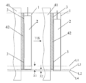
- Figure 16 shows a schematic diagram of movement between an electrode assembly and a housing of an optional electrochemical device according to an embodiment of the present application.
- Figure 17 shows a schematic diagram of an optional electrical device according to an embodiment of the present application.
- secondary batteries may include nickel metal hydride batteries, nickel cadmium batteries, lead-acid (or lead storage) batteries, lithium ion batteries, sodium ion batteries, polymer lithium ion batteries, and the like.
- the present application is explained by taking a lithium-ion battery as an example of an electrochemical device.
- the electrochemical device of the present application is not limited to lithium-ion batteries.
- it can also be a sodium-ion battery. etc.
- the embodiment of the present application provides an electrochemical device 10.
- the electrochemical device 10 includes: a housing 1, an electrode assembly 2 and a first adhesive Connecting portion 3; the electrode assembly 2 is disposed in the housing 1, and the first bonding portion 3 is disposed on the outer surface 11 of the housing 1, wherein the contact angle of the surface of the first bonding portion 3 away from the housing 1 is greater than 105 °.
- the first bonding portion 3 is provided on the outer surface 11 of the housing 1 of the electrochemical device 10, and the contact angle of the first bonding portion 3 away from the surface of the housing 1 is greater than 105°,
- the adhesive structure is attached, so that this part of the housing 1 can be partially deformed with the movement of the electrode assembly 2 when the electrode assembly 2 moves relative to the housing 1, thereby causing the impact of the electrode assembly 2 on this part of the housing 1
- Obtaining a certain degree of buffering reduces the impact of the electrode assembly 2 on this part of the housing 1, making the housing 1 less likely to be damaged, and furthermore, the electrochemical device 10 is also less likely to be damaged, thereby effectively increasing the service life of the electrochemical device. It reduces the safety risks for users when using electrochemical
- the electrochemical device 10 in the embodiment of the present application will be described in detail below. It can be understood that the following description is not intended to limit the embodiment of the present application in any way.
- the material of the casing 1 is not limited in the embodiments of this application. It can generally be made of metal.
- the casing 1 is made of metal plastic film.
- the housing 1 is made of aluminum-plastic film or steel-plastic film.
- the shape of the housing 1 is not limited in the embodiments of the present application.
- the housing 1 can be in the shape of a rectangular parallelepiped or an approximate rectangular parallelepiped (or the cross-section of the housing 1 in one direction can be a rectangular or approximately rectangular shape).
- the housing 1 shown in Figure 1 is a rectangular parallelepiped as a whole. To facilitate the description of the embodiment of the present application, an example will be given below.
- the specific structure of the electrode assembly 2 is not limited.
- the electrode assembly 2 may include a positive electrode tab, a separator, a negative electrode tab, an electrolyte, a positive electrode tab electrically connected to the positive electrode tab, and a negative electrode tab electrically connected to the negative electrode tab.
- the positive electrode tab is used to draw out the positive electrode of the electrochemical device 10 from the positive electrode piece
- the negative electrode tab is used to draw out the negative electrode of the electrochemical device 10 from the negative electrode piece.
- the electrode assembly 2 may be in a rolled shape, or may also be in a stacked shape, which is not subject to any limitation in the embodiment of the present application.
- the electrode assembly 2 is disposed in the housing 1 and has a certain gap with the housing 1 so that the electrode assembly 2 can move relative to the housing 1 within the housing 1 .
- the specific structure of the first bonding part 3 is not limited, and it may be a structure fixedly connected to the outer surface of the housing 1 (for example, the fixed connection method may be bonding, welding, etc.) , the contact angle ⁇ of the surface away from the housing 1 is greater than 105°.
- the contact angle ⁇ is also called the wetting angle, which can be understood with reference to Figure 2.
- the liquid droplet 5 (the size in Figure 2 is only an example) is dripped on the solid surface (corresponding to the first bonding part 3 in Figure 2
- the shape shown in the figure is formed on the surface (surface away from the shell 1), then the contact angle ⁇ is defined as follows: Situated on the solid-liquid-gas three-phase interface, the solid-gas interfacial tension is OSG, and the solid-liquid interfacial tension is is OSL, and the gas-liquid surface tension is OLG, then the contact angle ⁇ passes through the inside of the liquid to the gas-liquid interface at the three-phase boundary.
- the larger the contact angle ⁇ the harder it is to wet, the better the hydrophobicity, and the worse the surface stickiness.
- the contact angle ⁇ can be calculated and measured by taking the angle between the tangent to the droplet surface and the tangent to the solid surface at the point where the droplet contacts the solid surface. It can be understood that the contact angle ⁇ can be measured by a variety of different measurement methods, such as the tangent method, the width-height method, the ellipse method, the Laplace-Young method, etc., which can refer to related technologies and is not limited here. As an optional example, the measurement can be carried out in the following way: drop the liquid droplets onto the solid surface (corresponding to Figure 2, that is, the surface of the first bonding part 3 facing away from the housing 1) to form a shape as shown in Figure 2, so as to form a shape as shown in Figure 2.
- the angle of view in 2 captures the image of the liquid droplet and the solid surface; then determine the reference line in the image, which can be the dividing line between the solid surface and the liquid droplet and the two
- the line connecting three phase points that is, the intersection point of the solid-liquid-gas three-phase interface
- determine the outline of the droplet use an appropriate method to fit the outline curve of the droplet, and then calculate the contact angle ⁇ , and fit
- the method may be to differentially divide the droplet contour into multiple small parts, and then fit each small part, so as to be as close as possible to the true contour of the droplet and obtain better measurement results.
- an existing dedicated contact angle measurement machine can also be used to measure the contact angle ⁇ , which is not particularly limited in the embodiments of the present application.
- the component that provides the bonding ability of the bonding structure on the electrical equipment is actually an adhesive liquid, and the contact angle ⁇ of the surface of the first bonding part 3 away from the housing 1 in the embodiment of the present application is greater than 105°, thus making the electrical
- the casing 1 of the chemical device 10 is fixed to the electrical equipment, at least a part of the casing 1 is difficult to be adhered by the adhesive structure on the electrical equipment due to the presence of the first adhesive portion 3 .
- the contact angle ⁇ of the surface of the first bonding portion 3 facing away from the housing 1 is 120°-180°. In other embodiments, the contact angle ⁇ is 150°-180°. As the contact angle ⁇ increases, the viscosity of the surface of the first bonding part 3 will decrease, which can further reduce the impact of the electrode assembly 2 on the housing 1 (such as at the corner position), and further improve the service life of the electrochemical device. .
- the first peel strength between the first adhesive part 3 and the electrical equipment 4 is smaller than the first adhesive part 3 and the electrical equipment 4 .
- Peel strength refers to the maximum load per unit width required to separate two adherends of an adhesive under specified peel conditions.
- the first peel strength can express the strength between the first adhesive part 3 and the electrical equipment 4
- the bonding strength, the second peel strength can express the bonding strength between the first bonding portion 3 and the outer surface 11 of the housing 1 .
- the housing 1 is bonded to the electrical device 4 through the first bonding portion 3 , and the first peel strength between the first bonding portion 3 and the electrical device 4 is less than the first adhesive strength.
- the second peel strength between the connecting portion 3 and the outer surface 11 of the housing 1 enables the electrochemical device 10 to be stably installed to the electrical equipment 4, and the electrode assembly 2 in the housing 1 is relatively
- the casing 1 moves, the casing 1 can move to a certain extent relative to the electrical equipment 4 along with the movement of the electrode assembly 2 due to the existence of the first bonding portion 3, and is not easily hindered, thereby allowing the electrode assembly 2 to move with respect to the electrical equipment 4.
- the impact of the housing 1 is buffered to a certain extent, which reduces the impact of the electrode assembly 2 on the housing, making the housing 1 less likely to be damaged.
- the electrical equipment 4 includes a second bonding part 42.
- the second bonding part 42 is connected to the first bonding part 42.
- the third peel strength between parts 3 is less than the second peel strength.
- the third peel strength can express the bonding strength between the second adhesive portion 42 and the first adhesive portion 3 .
- the second bonding part 42 may be the aforementioned bonding structure on the electrical device, and the housing 1 and the first bonding part 3 are bonded to the second bonding structure of the electrical device 4 .
- the third peeling strength between the connecting portion 42 and the second bonding portion 42 and the first bonding portion 3 is smaller than the second peeling strength between the first bonding portion 3 and the outer surface 11 of the housing 1, such that
- the electrochemical device 10 can be stably installed on the electrical equipment 4
- the electrode assembly 2 in the housing 1 moves relative to the housing 1, the position corresponding to the position of the housing 1 and the first bonding portion 3 is due to
- the existence of the first adhesive part 3 makes it difficult for the second adhesive part 42 on the electrical equipment 4 to adhere, so that this part of the housing 1 can follow the movement of the electrode assembly 2 when the electrode assembly 2 moves relative to the housing 1 Partial deformation occurs, so that the impact of the electrode assembly 2 on this part of the casing 1 is buffered to a certain extent, which also reduces the impact of the electrode assembly
- the first peel strength or the third peel strength is less than 180gf/25mm.
- the first peel strength or the third peel strength is less than this value, it can effectively ensure that the housing 1 can partially deform with the movement of the electrode assembly 2 when the electrode assembly 2 moves relative to the housing 1, thereby causing the electrode assembly to 2
- the impact of the housing 1 is buffered to a certain extent.
- the test method for each peel strength in the embodiment of this application can adopt GB/T 2792-2014 "Test Method for Peel Strength of Adhesive Tapes".
- the first peel strength or the third peel strength is 0gf/25mm-150gf/25mm. In other embodiments, the first peel strength or the third peel strength is 0gf/25mm-90gf/25mm. As the peeling strength decreases, the viscosity of the surface of the first bonding part 3 will also decrease, which can further reduce the impact of the electrode assembly 2 on the housing 1 (such as at the corner position), and further improve the performance of the electrochemical device. service life.
- the second bonding part 42 may be one or more, for example, one or more double-sided tapes provided on the electrical equipment 4, one side of which is bonded to the electrical equipment 4, and the other side is used for The first bonding portion 3 and the outer surface 11 of the housing 1 are bonded together to stably fix the electrochemical device to the electrical equipment 4 .
- their sizes and shapes can be different from each other, as long as they meet the needs, and this is not limited in the embodiment of the present application.
- FIGS. 3 to 7 show schematic diagrams of the second bonding portion 42 of different sizes and shapes at different positions
- the bonding portion 42 is used to facilitate the display of the position of the second bonding portion 42 between the device body 41 and the housing 1 of the electrical device 4.
- the second bonding portion 42 can also be placed on the electrical device in conjunction with the second bonding portion 42 in Figure 14. 4 to understand the position between the device main body 41 and the housing 1.
- Figures 3-7 and 14 are only used to facilitate understanding of the embodiments of the present application and should not be regarded as any limitations to the present application.
- the first bonding portion 3 is provided at at least one corner of the outer surface 11 of the housing 1 of the electrochemical device 10 in the embodiment of the present application.
- the angular position of the outer surface 11 of the housing 1 refers to the area near the intersection between adjacent sides of the outer surface 11 of the housing 1. Since the included angle is formed between two adjacent sides, , so it will be called the angle position.
- the housing 1 is in the shape of a rectangular parallelepiped, and the outer surface 11 of the housing 1 is a rectangle. It has four corner positions, and the four corner positions are located at each adjacent corner of the rectangle. Near the intersection of two sides.
- the various edges and corners on the electrode assembly 2 of the electrochemical device 10 are generally distributed near each corner of the electrode assembly 2, they are respectively affected by the corresponding positions on the outer surface 11 of the housing 1.
- Each corner position is covered, so when the corners of the outer surface 11 of the housing 1 are bonded by the bonding structure of the electrical equipment 4 (such as the aforementioned second bonding structure 42), the housing 1 cannot occur due to the bonding effect.
- the bonding structure of the electrical equipment 4 such as the aforementioned second bonding structure 42
- the first bonding portion 3 is provided on at least one corner position of the outer surface 11 of the housing 1 of the electrochemical device 10 , and the first bonding portion 3 is away from contact with the surface of the housing 1
- the angle is greater than 105°, so that when the casing 1 of the electrochemical device 10 is fixed to the electrical equipment, at least one angle position on the casing 1 is less likely to be attached to the electrical equipment 4 due to the presence of the first adhesive portion 3
- the second adhesive part 42 i.e., the aforementioned adhesive structure
- the second adhesive part 42 is not likely to constrain and hinder the deformation of the housing 1.
- the housing 1 can move the electrode assembly 2 relative to the housing 1.
- first bonding portions 3 are respectively provided at 2 to 4 corners of the outer surface 11 of the housing 1 .
- the surface 11 of the housing 1 generally does not have only one corner position. Therefore, in this application, first bonding portions 3 are respectively provided at 2 to 4 corner positions of the outer surface 11 of the housing 1, which can provide more comprehensive protection.
- the housing 1 prevents the housing 1 of the electrochemical device 10 from being damaged.
- FIG. 7 shows an example in which first bonding portions 3 are respectively provided at two corners of the outer surface 11 of the housing 1 ;
- Example of adhesive part 3. However, it should be understood that these examples do not serve as any limitations to this application.
- the first bonding part 3 is a coating structure.
- the first bonding part 3 in the form of a coating can be disposed on the outer surface of the housing 1 more stably and does not occupy an excessively large volume, which is beneficial to reducing the volume and weight of the electrochemical device.
- the first bonding part 3 of the coating structure obviously causes less damage to the housing 1 and makes the manufacturing process of the electrochemical device 10 simpler.
- first bonding part 3 shown in FIGS. 3 to 7 and 14 may be a coating structure. Of course, this does not limit the embodiments of the present application.
- the material of the first bonding part 3 includes at least one of silicon oxide, polysiloxane, and polytetrafluoroethylene.
- the first bonding part 3 can be a silicon oxide coating, a polysiloxane coating, a polytetrafluoroethylene coating, or a silicon oxide, polyethylene coating. Silicone, polytetrafluoroethylene or a mixed coating of the three.
- the contact angle ⁇ of the surface away from the housing 1 is greater than 105°, which can meet the usage requirements.
- each first bonding part 3 is a rectangle, a sector, a triangle, a trapezoid, a closed figure formed by two outer tangents of a circle and a circular arc, or One of the n-sided polygons (n ⁇ 5).
- the embodiments of the present application provide the first bonding part 3 with various cross-sectional shapes to meet the requirements of different shapes of the housing 1 and also provide more choices for the preparation of electrochemical devices.
- the cross section of the first bonding portion 3 may be a cross section along a direction perpendicular to the outer surface 11 of the housing 1 .
- its cross section along the direction perpendicular to the outer surface 11 of the housing 1 is also the cross section in the thickness direction of the coating.
- the cross-sectional shape of the first bonding part 3 when the cross-sectional shape of the first bonding part 3 is a rectangle, it may be a square, that is, the length and width of the rectangle are equal.
- the cross-sectional shape of the first bonding part 3 when the cross-sectional shape of the first bonding part 3 is a trapezoid, it may be a right-angled trapezoid.
- the cross-sectional shape of the first bonding portion 3 is n-gonal (n ⁇ 5), it may have at least one right angle.
- the cross-sectional shapes of each first bonding portion 3 are the same. Referring to Figures 8 to 13, an example is shown in which the cross-sectional shapes of each first bonding portion 3 are the same. In Figure 8, the cross-sections of each first bonding portion 3 are rectangles with the same shape. Figures 9 and 13 In FIG. 10 , the cross section of each first bonding part 3 is a triangle with the same shape (for example, a right triangle in FIG. 9 and an acute triangle in FIG. 13 ). The same trapezoid (a right-angled trapezoid in Figure 10). In Figure 11, the cross-section of each first bonding portion 3 is a fan-shaped shape.
- each first bonding portion 3 is a circle with the same shape.
- the first bonding part 3 shown in FIGS. 8 to 13 is a coating structure. Of course, this does not serve as any limitation on the embodiments of the present application.
- each first bonding portion 3 has equal lengths. Still referring to Figures 8-13, some such examples are shown simultaneously.
- each first bonding portion 3 coincides with an edge of the outer surface 11 of the housing 1 . Since at least one edge of the first bonding portion 3 in the embodiment of the present application coincides with the edge of the outer surface 11 of the housing 1, when the electrode assembly 2 inside the housing 1 moves relative to the housing 1, the The edge of the outer surface 11 is not easily adhered by the adhesive structure (such as the aforementioned second adhesive part 42) on the electrical equipment 4, and the adhesive structure is not likely to hinder the deformation of the housing 1.
- the adhesive structure such as the aforementioned second adhesive part 42
- the housing 1 can be used in the electrode assembly 2 is partially deformed as the electrode assembly 2 moves relative to the housing 1, so that the impact of the electrode assembly 2 on the housing 1 is buffered to a certain extent, which also reduces the impact of the electrode assembly 2 on the housing 1. impact, making the housing 1 less likely to be damaged.
- FIGS. 8 to 13 for understanding which also shows an example in which the shape of the cross section of the first bonding portion 3 in FIG. 13 is a triangle, and one side coincides with the edge of the outer surface 11 of the housing 1 .
- each first bonding portion 3 coincide with the edges of the outer surface 11 of the housing 1 respectively.
- the first bonding part 3 when the outer surface 11 of the housing 1 is rectangular, and the cross-sectional shape of the first bonding part 3 is a rectangle, a triangle, a trapezoid, or an n-gon (n ⁇ 5), the first bonding part 3
- the side lengths d1 and d2 of the two sides where the connecting portion 3 coincides with the edges of the outer surface 11 of the housing 1 respectively satisfy: 0.05W ⁇ d1 ⁇ 0.35W and 0.05L ⁇ d2 ⁇ 0.35L; or, 0.05L ⁇ d1 ⁇ 0.35L and 0.05W ⁇ d2 ⁇ 0.35W; where W is the width of the housing 1 and L is the length of the housing 1.
- the outer surface of the first bonding part 3 and the housing 1 respectively satisfy: 0.05W ⁇ d1 ⁇ 0.25W and 0.05L ⁇ d2 ⁇ 0.25L; or, 0.05L ⁇ d1 ⁇ 0.25L and 0.05W ⁇ d2 ⁇ 0.25W ; Where, W is the width of the housing 1, and L is the length of the housing 1. This can ensure the installation stability of the electrochemical device and meet the needs.
- the first bonding part 3 and the outer surface of the housing 1 are a rectangle, a triangle, a trapezoid, or an n-gon (n ⁇ 5)
- the first bonding part 3 and the outer surface of the housing 1 The side lengths d1 and d2 of the two coincident edges of the surface 11 respectively satisfy: 0.1W ⁇ d1 ⁇ 0.25W and 0.1L ⁇ d2 ⁇ 0.25L; or, 0.1L ⁇ d1 ⁇ 0.25L and 0.1W ⁇ d2 ⁇ 0.25 W, where W is the width of the housing 1 and L is the length of the housing 1. This can better ensure the installation stability of the electrochemical device and meet the needs.
- the cross-sectional shape of the first bonding portion 3 is a rectangle, a triangle, or a trapezoid, it can be understood with reference to FIG. 8 , FIG. 9 , and FIG. 10 respectively, and will not be described again here.
- d1 and d2 can respectively satisfy: 2mm ⁇ d1 ⁇ 5mm and 3mm ⁇ d2 ⁇ 0.75mm, or, 3mm ⁇ d1 ⁇ 0.75 mm and 2mm ⁇ d2 ⁇ 5mm.
- the first bonding part 3 The cross-sectional shape of the connecting portion 3 can be a square (that is, a rectangle with equal length and width), an isosceles right triangle, a trapezoid with two equal perpendicular sides, or an n-gon (n ⁇ 5) (the two perpendicular sides The edges are the two edges where the first bonding portion 3 overlaps with the edge of the outer surface 11 of the housing 1).
- the outer surface 11 of the housing 1 is rectangular, and the cross-sectional shape of the first bonding portion 3 is a sector shape or is composed of two outer tangents of a circle with the same shape and a circular arc.
- the radius R of the sector or the arc radius R of the closed figure satisfies:
- the cross-sectional shape of the first bonding portion 3 is a fan shape, and the cross-sectional shape of the first bonding portion 3 is a circle with the same shape, two outer tangent lines and a circle.
- the cross-sectional shape of the first bonding portion 3 is a sector or a closed figure formed by two outer tangents of a circle with the same shape and an arc of the circle, the radius of the sector or the closed figure The arc radius R of length. This can ensure the installation stability of the electrochemical device and meet the needs.
- the radius of the sector or the closed figure satisfies: if W ⁇ L, then 0.1W ⁇ R ⁇ 0.25W; if W>L, then 0.1L ⁇ R ⁇ 0.25L; where W is the width of shell 1 and L is the shell 1 length. This can better ensure the installation stability of the electrochemical device and meet the needs.
- the circular angle of the sector is 90°.
- the case 1 is made of aluminum plastic film or steel plastic film, has a cuboid shape, the outer surface 11 is a rectangle, the electrode assembly 2 is a rolled electrode assembly, the first bonding part 3 is a coating structure, 4 The first bonding parts 3 are respectively located at four corners of the outer surface 11.
- the second bonding parts 42 on the electrical equipment 4 are double-sided tape, for example.
- FIG. 15 the prior art solution that does not adopt the electrochemical device 10 in this application will be briefly introduced.
- an electrochemical device 10 installed on the equipment body 41 of the electrical equipment 4 in an existing solution is shown. Since the four corners of the outer surface 11 of the housing 1 are covered by the equipment body 1
- the second adhesive part 42 (for example, double-sided tape) is adhered and fixed, and the electrode assembly 2 has a certain moving space in the housing.
- the electrical equipment 4 moves (for example, the electrical equipment 4 falls or the user uses the electrical equipment) (swinging, etc.), the electrochemical device 10 moves as a whole.
- the electrode assembly 2 continues to move relative to the casing 1 in the casing 1 due to inertia.
- the casing 1 is moved by the four corners of the outer surface 11.
- the second bonding part 42 is fixed and cannot move (refer to FIG. 15 , during the falling process of the housing 1 , the electrode assembly 2 moves downward by a distance Y relative to the housing 1 , while the housing 1 is moved by the second bonding part 42 Therefore, the electrode assembly 2 has a large impact on the housing 1, and the area near the corner of the outer surface 11 of the housing 1 is easily damaged by the impact of the electrode assembly 2.
- the electrochemical device 10 is installed on the equipment body 41 of the electrical equipment 4, and is adhered and fixed by the second adhesive portion 42 (for example, double-sided tape) on the equipment body 1.
- the shell of the electrochemical device 10 First bonding portions 3 are provided at four corners of the outer surface 11 of the body 1.
- the first bonding portion 3 is a coating structure coated on the outer surface 11 of the housing 1, and the first bonding portion 3 is The contact angle ⁇ of the surface of the part 3 away from the housing 1 is greater than 105°, the first adhesive part 3 is in contact with the second adhesive part 42, and the peel strength between the first adhesive part 3 and the second adhesive part 42 is ( That is, the third peel strength) is smaller than the peel strength between the housing 1 and the second bonding portion 42 (that is, the second peel strength). In this way, the housing 1 can be stably bonded to the electrical appliance by the second bonding portion 42.
- the four corners of the outer surface 11 of the housing 1 are isolated by the first bonding part 3 and the second bonding part 42, so that the four corners of the housing 1 are not easily blocked by the second bonding part 3.
- the two bonding parts 42 are attached, and the second bonding part 42 will not constrain or hinder the deformation of the housing 1 , so that this part of the housing 1 can follow the electrode assembly 2 when the electrode assembly 2 moves relative to the housing 1 Partial deformation occurs due to the movement (refer to Figure 16, during the falling process of the housing 1, the electrode assembly 2 moved downwards by the X1 distance relative to the housing 1 (the distance between the dotted lines L1 and L2), and this part of the housing 1
- the area is deformed relative to the electrical equipment 4 by a distance of The impact on this part of the casing 1 makes it difficult for the casing 1 to be damaged, and thus the electrochemical device 10 is also less likely to be damaged, thereby effectively increasing the service life of the electrochemical device and reducing the user's cost when using the electrochemical
- the first bonding portion 3 is provided on the outer surface 11 of the housing 1 of the electrochemical device 10, and the contact angle of the first bonding portion 3 away from the surface of the housing 1 is It is greater than 105°, which makes the case 1 of the electrochemical device 10 in the embodiment of the present application difficult to be used by electricity due to the presence of the first adhesive portion 3 when the case 1 is fixed to the electrical equipment.
- the device 4 or the adhesive structure thereon is attached, so that the housing 1 of this part can be partially deformed with the movement of the electrode assembly 2 when the electrode assembly 2 moves relative to the housing 1, thereby causing the electrode assembly 2 to
- the impact of the casing 1 is buffered to a certain extent, which reduces the impact of the electrode assembly 2 on this part of the casing 1, making the casing 1 less likely to be damaged, and furthermore, the electrochemical device 10 is also less likely to be damaged, thereby effectively improving the electrochemical performance.
- the service life of the device reduces the safety risks of users when using electrochemical devices (including but not limited to lithium-ion batteries or sodium-ion batteries, etc.).
- the embodiment of the present application provides an electrical equipment 4, which includes: an equipment body 41; and any one of the aforementioned electrochemical devices 10.
- the electrochemical device 10 is used to supply power to the device body 41.
- the electrical equipment 4 includes a second bonding part 42 , and the second bonding part 42 is connected to the first bonding part 3 on the electrochemical device 10
- the peeling strength between them (that is, the aforementioned third peeling strength) is smaller than the peeling strength between the second bonding portion 42 and the outer surface 11 of the housing 1 of the electrochemical device 10 (that is, the aforementioned second peeling strength).
- the electrical equipment 4 in the embodiment of the present application has been described in detail in conjunction with the previous embodiment of the electrochemical device 10.
- the electrical equipment 4 in the embodiment of the present application includes the electrochemical device 10 provided in the embodiment of the present application, the electrochemical device 10 of the electrical equipment 4 is not easily damaged, has a better service life, and can supply power more stably. Therefore, the electrical equipment 4 also has a better service life and is safer for users to use.
- the term “include” and its variations are open-ended, ie, “including but not limited to.”
- the term “based on” means “based at least in part on.”
- the term “one embodiment” means “at least one embodiment”; the term “another embodiment” means “at least one additional embodiment”; and the term “some embodiments” means “at least some embodiments”.
- Relevant definitions of other terms will be given in the description below. It should be noted that concepts such as “first” and “second” mentioned in this application are only used to distinguish different devices, modules or units, and are not used to limit the order of functions performed by these devices, modules or units. Or interdependence.
Landscapes
- Chemical & Material Sciences (AREA)
- Chemical Kinetics & Catalysis (AREA)
- Electrochemistry (AREA)
- General Chemical & Material Sciences (AREA)
- Engineering & Computer Science (AREA)
- Manufacturing & Machinery (AREA)
- Sealing Battery Cases Or Jackets (AREA)
- Battery Mounting, Suspending (AREA)
Abstract
本申请实施例提供了一种电化学装置及电子设备,该电化学装置包括:壳体、电极组件以及第一粘接部;电极组件设置在壳体内,第一粘接部设置在壳体的外表面上,其中,第一粘接部背离壳体的表面的接触角大于105°。本申请实施例中的电化学装置更不易损坏。
Description
本申请实施例涉及电化学技术领域,尤其涉及一种电化学装置及用电设备。
二次电池具有比能量密度大、循环寿命长、标称电压高、自放电率低、体积小、重量轻等许多优点,在新能源领域具有广泛的应用。近年随着平板电脑、手机、电动交通工具、储能设备的高速发展,并且由于新能源行业的不断发展,二次电池变得越来越重要,市场对二次电池的需求也越来越多。
相关技术中,该二次电池包括电极组件,且用壳体包裹在电极组件外以制成二次电池,这类二次电池中,电极组件往往存在棱角,并且在壳体内存在一定的移动空间,在实际安装到用电设备中进行使用时需要将壳体的外表面粘接在用电设备上。由于在用电设备的使用过程中,往往会使得用电设备大幅度移动,造成内部的二次电池的电极组件相对于壳体移动,使得电极组件对壳体进行碰撞,长时间下容易使得壳体上对应位置发生损坏,进而容易导致二次电池的损坏,并且也对用户使用二次电池造成了安全风险。
发明内容
有鉴于此,本申请实施例提供一种电化学装置及用电设备,以至少部分解决上述问题。
根据本申请实施例的一方面,提供了一种电化学装置,包括:壳体、电极组件以及第一粘接部;电极组件设置在壳体内,第一粘接部设置在壳体的外表面上,其中,第一粘接部背离壳体的表面的接触角大于105°。
在一些可选的实施例中,壳体的外表面的至少一个角位设置有第一粘接部。
在一些可选的实施例中,壳体的外表面的2至4个角位分别设置有第一粘接部。
在一些可选的实施例中,第一粘接部为涂层结构。
在一些可选的实施例中,第一粘接部的材质包括氧化硅、聚硅氧烷、聚四氟乙烯中的至少一种。
在一些可选的实施例中,各第一粘接部的横截面形状为矩形、扇形、三角形、梯形、正方形、圆形的两条外切线与圆形的弧形构成的封闭图形、或n边形(n≥5)中的一种。
在一些可选的实施例中,各第一粘接部的横截面形状相同。
在一些可选的实施例中,各第一粘接部的至少两个边的边长相等。
在一些可选的实施例中,各第一粘接部的至少一个边与壳体的外表面的边缘重合。
在一些可选的实施例中,各第一粘接部的两个边分别与壳体的外表面的边缘重合。
在一些可选的实施例中,第一粘接部的横截面形状为扇形或封闭图形时,扇形的半径或封闭图形的圆弧半径R满足:若W<L,则0.05W≤R≤0.35W;若W>L,则0.05L≤R≤0.35L;其中,W为壳体的宽度,L为壳体的长度。
在一些可选的实施例中,第一粘接部的横截面形状为矩形、三角形、梯形、或n边形(n≥5)时,第一粘接部与壳体的外表面的边缘重合的两条边的边长d1、d2分别满足:0.05W≤d1≤0.35W且0.05L≤d2≤0.35L;或者,0.05L≤d1≤0.35L且0.05W≤d2≤0.35W;其中,W为壳体的宽度,L为壳体的长度。
在一些可选的实施例中,当第一粘接部粘贴在用电设备时,第一粘接部与用电设备之间的第一剥离强度小于第一粘接部与壳体的外表面之间的第二剥离强度。
在一些可选的实施例中,用电设备包括第二粘接部,当第一粘接部粘接于第二粘接部时,第二粘接部与第一粘接部之间的第三剥离强度小于第二剥离强度。
在一些可选的实施例中,第一剥离强度或第三剥离强度小于180gf/25mm。
根据本申请实施例的另一方面,还提供了一种用电设备,该用电设备包括设备主体以及如前述的电化学装置,电化学装置用于为设备主体供电。
本申请实施例提供的电化学装置及用电设备,由于该电化学装置的壳体的外表面上设置有第一粘接部,而第一粘接部背离壳体的表面的接触角大于105°,其使得本申请实施例中的电化学装置的壳体在被固定到用电设备时,壳体上的至少一部分因该第一粘接部的存在不易被用电设备或其上的粘接结构附着,使得该部分的壳体可以在电极组件相对于壳体移动时随着电极组件的运动而发生部分形变,从而令电极组件对于该部分壳体的冲击得到一定程度的缓冲,也就减轻了电极组件对该部分壳体(如角位等)的冲击,使得壳体不易因此损坏,进而电化学装置也不易损坏,从而有效提高了电化学装置的使用寿命,降低了用户在使用电化学装置(包括但不限于锂离子电池或钠离子电池等)的安全风险。
为了更清楚地说明本申请实施例的技术方案,下面将对本申请中所需要使用的附图作简单地介绍,显而易见地,下面描述中的附图仅仅是本申请实施例中记载的一些实施例,对于本领域普通技术人员来讲,还可以根据这些附图获得其他的附图。
图1示出了根据本申请实施例的一个可选的电化学装置的结构示意图。
图2示出了根据本申请实施例的第一粘接部背离壳体的表面的接触角的示意图。
图3示出了根据本申请实施例的一个可选的用电设备上的第二粘接部的结构示意图。
图4示出了根据本申请实施例的另一个可选的用电设备上的第二粘接部的结构示意图。
图5示出了根据本申请实施例的再一个可选的用电设备上的第二粘接部的结构示意图。
图6示出了根据本申请实施例的再一个可选的用电设备上的第二粘接部的结构示意图。
图7示出了根据本申请实施例的再一个可选的用电设备上的第二粘接部的结构示意图。
图8示出了根据本申请实施例的一种可选的第一粘接部的横截面的形状的示意图。
图9示出了根据本申请实施例的另一种可选的第一粘接部的横截面的形状的示意图。
图10示出了根据本申请实施例的再一种可选的第一粘接部的横截面的形状的示意图。
图11示出了根据本申请实施例的再一种可选的第一粘接部的横截面的形状的示意图。
图12示出了根据本申请实施例的再一种可选的第一粘接部的横截面的形状的示意图。
图13示出了根据本申请实施例的再一种可选的第一粘接部的横截面的形状的示意图。
图14示出了根据本申请实施例的一个角度的第二粘接部的位置示意图。
图15示出了根据现有技术中的电化学装置的电极组件和壳体之间移动的示意图。
图16示出了根据本申请实施例的可选的电化学装置的电极组件和壳体之间移动的示意图。
图17示出了根据本申请实施例的一个可选的用电设备的示意图。
为了使本领域的人员更好地理解本申请实施例中的技术方案,下面将结合本申请实施例中的附图,对本申请实施例中的技术方案进行清楚、详细地描述,显然,所描述的实施例仅是本申请实施例一部分实施例,而不是全部的实施例。基于本申请中的实施例,本领域普通技术人员所获得的所有其他实施例,都应当属于本申请实施例保护的范围。
下面结合附图说明本申请实施例具体实现。
需要说明的是,二次电池(可充电电池)可以包括镍氢电池、镍镉电池、铅酸(或铅蓄)电池、锂离子电池、钠离子电池、聚合物锂离子电池等。在本申请实施例的内容中,以锂离子电池作为电化学装置的例子来解释本申请,但是如前述,本申请的电化学装置并不仅限于锂离子电池,例如,其还可以是钠离子电池等等。
根据本申请实施例中的一方面,如图1-图17所示,本申请实施例提供了一种电化学装置10,该电化学装置10包括:壳体1、电极组件2以及第一粘接部3;电极组件2设置在壳体1内,第一粘接部3设置在壳体1的外表面11上,其中,第一粘接部3背离壳体1的表面的接触角大于105°。
本申请实施例中,由于该电化学装置10的壳体1的外表面11上设置有第一粘接部3,而第一粘接部3背离壳体1的表面的接触角大于105°,其使得本申请实施例中的电化学装置10的壳体1在被固定到用电设备时,壳体1上的至少一部分因该第一粘接部3的存在不易被用电设备或其上的粘接结构附着,使得该部分的壳体1可以在电极组件2相对于壳体1移动时随着电极组件2的运动而发生部分形变,从而令电极组件2对于该部分壳体1的冲击得到一定程度的缓冲,也就减轻了电极组件2对该部分壳体1的冲击,使得壳体1不易因此损坏,进而电化学装置10也不易损坏,从而有效提高了电化学装置的使用寿命,降低了用户在使用电化学装置(包括但不限于锂离子电池或钠离子电池等)的安全风险。
下面对本申请实施例中的电化学装置10进行具体的说明,可以理解的是,下文中的说明并不做为对本申请实施例中的任何限制。
本申请实施例中不限制壳体1的材质,其一般可以为金属制成,例如在本申请的一些可选的电化学装置10中,壳体1由金属塑膜制成,在其中一些示例中,壳体1由铝塑膜或者钢塑膜制成。此外,本申请实施例中亦不限制壳体1的形状,例如,壳体1可以为长方体形状或者近似的长方体形状(或者壳体1在一个方向上的截面可以为长方形或者近似长方形的形状),如图1中所示的壳体1,其整体为一个长方体,为便于说明本申请实施例,下文中以其进行举例。
本申请实施例中,不限制电极组件2的具体结构。作为示例地,电极组件2可以包括正极极片、隔离膜、负极极片、电解液、与正极极片电连接的正极极耳、与负极极片电连接的负极极耳,对于电化学装置10而言,正极极耳用于将电化学装置10的正极从正极极片上引出,负极极耳用于将电化学装置10的负极从负极极片上引出。该示例里,电极组件2的正极极片、隔离膜、负极极片等可以为卷绕状,或者也可以为堆叠状,本申请实施例中对此不进行任何限制。本申请实施例中,电极组件2设置于壳体1内,且与壳体1存在一定的空隙,使得电极组件2可以在壳体1内相对于壳体1移动。
本申请实施例中,不限制第一粘接部3的具体结构,其可以是固定连接在壳体1的外表面上的一个结构(例如,固定连接的方式可以是粘接、焊接等等),其背离壳体1的表面的接触角θ大于105°。
相关技术中,接触角θ也称为润湿角,参照图2进行理解,液滴5(图2中的大小仅作为示例)滴在固体表面(对应于图2也即第一粘接部3背离壳体1的表面)上形成如图的形状,则接触角θ的定义如下:设在固-液-气三相界面上,固-气的界面张力为的OSG,固-液的界面张力为OSL,气-液的表面张力为OLG,则接触角θ在三相界处经过液体内部到气液界面的夹角,三相界面张力一般服从杨氏方程:OSG=OSL+OLGcosθ。一般来讲,接触角θ的大小是判定润湿性好坏的判据。若θ=0°,cosθ=1,液体完全润湿固体表面,液体在固体表面铺展;0°<θ<90°,液体可润湿固体,且θ越小,润湿性越好;90°<θ<180°,液体不润湿固体,θ=180°,完全不润湿,液体在固体表面凝聚成小球。一般而言,接触角θ越大,润湿越难,疏水性越好,表面粘性越差。
接触角θ可以通过在液滴与固体表面接触处做液滴表面的切线与固体表面之间的切线之间的夹角来计算和测定。可以理解的是,接触角θ可以通过多种不同的测定方法进行测定,例如切线法、宽高法、椭圆法、Laplace-Young法,等等,其可以参照相关技术,在此不进行限制。作为一个可选的示例,例如可以采用如下方式测定:将液滴滴到固体表面(对应于图2也即第一粘接部3背离壳体1的表面)形成如图2的形状,以图2中的视角(可以理解为沿平行于该固体表面方向的视角)拍摄液滴与固体表面的图像;之后在图像中确定基准线,该基准线可以是固体表面与液滴的分界线以及两个三相点(即固-液-气三相界面的交点)之间的连线;确定液滴的外形轮廓,采用适当方式拟合液滴的外形曲线,再计算得到接触角θ,拟合方式例如可以是将液滴轮廓微分分成多个小部分,再对每个小部分进行拟合,从而能够最大限度接近 液滴的真实外形轮廓,以获得更好的测定结果。或者在其他测定方式中,也可以采用现有专用的接触角测量机器进行接触角θ测定,本申请实施例中不进行特别限制。
需要说明的是,图2中的第一粘接部3的位置、形状和厚度仅作为示例,不作为对本申请实施例中任何限制。
由于用电设备上的粘接结构提供粘接能力的成分实际为胶粘剂液体,而本申请实施例中的第一粘接部3背离壳体1的表面的接触角θ大于105°,因而使得电化学装置10的壳体1在被固定到用电设备时,壳体1上的至少一部分因该第一粘接部3的存在不易被用电设备上的粘接结构附着。
在一些实施例中,第一粘接部3背离壳体1的表面的接触角θ为120°-180°。在另一些实施例中,接触角θ为150°-180°。随着接触角θ的增大,第一粘接部3表面的粘性会减小,能够进一步减轻电极组件2对壳体1(如角位处)的冲击,进一步提高了电化学装置的使用寿命。
在一些可选的实施例中,当第一粘接部3粘贴在用电设备4时,第一粘接部3与用电设备4之间的第一剥离强度小于第一粘接部3与壳体1的外表面11之间的第二剥离强度。
剥离强度是指在规定的剥离条件下使粘接件的两个被粘物分离时单位宽度所需的最大载荷,第一剥离强度能够表现第一粘接部3与用电设备4之间的粘接的强度,第二剥离强度能够表现第一粘接部3与壳体1的外表面11之间的粘接的强度。
在这些可选的实施例中,壳体1通过第一粘接部3与用电设备4形成粘接,第一粘接部3与用电设备4之间的第一剥离强度小于第一粘接部3与壳体1的外表面11之间的第二剥离强度,在使得在电化学装置10能够被稳定的安装到用电设备4的基础上,壳体1内的电极组件2相对于壳体1移动时,壳体1因第一粘接部3的存在可一同随电极组件2的移动相对于用电设备4发生一定程度的移动,而不易受阻碍,从而令电极组件2对于该壳体1的冲击得到一定程度的缓冲,也就减轻了电极组件2对该壳体的冲击,使得壳体1不易因此损坏。
在一些可选的实施例中,用电设备4包括第二粘接部42,当第一粘接部3粘接于第二粘接部42时,第二粘接部42与第一粘接部3之间的第三剥离强度小于第二剥离强度。
与第一剥离强度、第二剥离强度同理,第三剥离强度能够表现第二粘接部42与第一粘接部3之间的粘接的强度。
在这些可选的实施例中,该第二粘接部42可以是前述的用电设备上的粘接结构,壳体1和第一粘接部3粘接于用电设备4的第二粘接部42,第第二粘接部42与第一粘接部3之间的第三剥离强度小于第一粘接部3与壳体1的外表面11之间的第二剥离强度,在使得在电化学装置10能够被稳定的安装到用电设备4的基础上,壳体1内的电极组件2相对于壳体1移动时,壳体1与第一粘接部3位置对应的部分因第一粘接部3的存在不易被用电设备4上的第二粘接部42附着,使得该部分的壳体1可以在电极组件2相对于壳体1移动时随着电极组件2的运动而发生部分形变,从而令电极组件2对于该部分壳体1的冲击得到一定程度的缓冲,也就减轻了电极组件2对该部分壳体1的冲击,使得壳体1不易因此损坏,进而电化学装置10也不易损坏,从而有效提高了电化学装置的使用寿命,降低了用户在使用电化学装置(包括但不限于锂离子电池或钠离子电池等)的安全风险。
在一些可选的实施例中,第一剥离强度或第三剥离强度小于180gf/25mm。当第一剥离强度或第三剥离强度小于这一值时,可以有效保证壳体1可以在电极组件2相对于壳体1移动时随着电极组件2的运动而发生部分形变,从而令电极组件2对于壳体1的冲击得到一定程度的缓冲。本申请实施例中各剥离强度的测试方法可采用GB/T 2792-2014《胶粘带剥离强度的测试方法》。
在一些实施例中,第一剥离强度或第三剥离强度为0gf/25mm-150gf/25mm。在另一些实施例中,第一剥离强度或第三剥离强度为0gf/25mm-90gf/25mm。随着剥离强度的减小,第一粘接部3表面的粘性也会随着减小,能够进一步减轻电极组件2对壳体1(如角位处)的冲击,进一步提高了电化学装置的使用寿命。
本申请实施例中,第二粘接部42可以是一个或者多个,例如是设置在用电设备4的一个或者多个双面胶,其一面粘接于用电设备4,另一面用于粘接第一粘接部3和壳体1的外表面11,起到将电化学装置稳定固定在用电设备4上的作用。第二粘接部42为多个时,其大小和形状可以彼此不同,能够满足需求即可,本申请实施例中对此不进行限制。
参照图3-图7中的示例,其示出了不同位置不同大小形状的第二粘接部42的示意,可以理解的是,图3-图7之所以用虚线示意性地表示出第二粘接部42,是为了便于显示出第二粘接部42在用电设备4的设备主体41与壳体1之间的位置,进一步也可以结合图14第二粘接部42在用电设备4的设备主体41与壳体1之间的位置进行理解。对于图3-图7以及图14其仅用于便于理解本申请实施例而不应视为对本申请中的任何限制。
在一些可选的实施例中,本申请实施例中的电化学装置10的壳体1的外表面11的至少一个角位设置有第一粘接部3。
本申请实施例中,壳体1的外表面11的角位是指壳体1的外表面11的各个相邻的边之间的交点附近区域,由于相邻的两个边之间形成夹角,因此将至称之为角位。以图1中的电化学装置10来举例,壳体1整体为长方体形状,壳体1的外表面11为矩形,则其有4个角位,4个角位分别位于矩形的每相邻的两个边的交点附近。
由于电化学装置10的电极组件2上的各个棱角(也即电极组件2上的应力集中的位置)一般分布于电极组件2的各个角位附近,分别被壳体1的外表面11对应位置的各个角位包覆,因此壳体1的外表面11的角位被用电设备4的粘接结构(例如前述的第二粘接结构42)粘接时,壳体1因粘接作用不能发生形变,当此时电极组件2在壳体1内相对于壳体1运动时,各个电极组件2更容易对壳体1的各个角位附近的区域进行冲击,长时间后更容易造成壳体1的角位附近的区域发生损坏。
因此,本申请实施例中的电化学装置10的壳体1的外表面11的至少一个角位上设置第一粘接部3,而该第一粘接部3背离壳体1的表面的接触角大于105°,能够使得电化学装置10的壳体1在被固定到用电设备时,壳体1上的至少一个角位因该第一粘接部3的存在不易被用电设备4上的第二粘接部42(即前述的粘接结构)附着,第二粘接部42不易对壳体1的形变产生束缚和阻碍,壳体1可以在电极组件2相对于壳体1移动时随着电极组件2的运动而发生部分形变,从而令电极组件2对于该壳体1的角位的冲击得到一定程度的缓冲,也就减轻了电 极组件2对该壳体1的角位的冲击,使得壳体1不易因此损坏,进而电化学装置10也不易损坏,从而有效提高了电化学装置10的使用寿命,降低了用户在使用电化学装置(包括但不限于锂离子电池或钠离子电池等)的安全风险。
在一些可选的实施例中,壳体1的外表面11的2至4个角位分别设置有第一粘接部3。显然,壳体1的表面11一般不会只有一个角位,因此本申请中壳体1的外表面11的2至4个角位分别设置有第一粘接部3,可以更全方向的保护壳体1,防止电化学装置10的壳体1损坏。
可参照图7理解,其示出了壳体1的外表面11的2个角位分别设置有第一粘接部3的示例;参照图5和图6理解,其示出了壳体1的外表面11的3个角位分别设置有第一粘接部3的示例;参照图3和图4理解,其分别示出了壳体1的外表面11的4个角位分别设置有第一粘接部3的示例。但可以理解的是,这些示例并不作为对本申请的任何限制。
在一些可选的实施例中,第一粘接部3为涂层结构。涂层形式的第一粘接部3可以更稳定地设置于壳体1的外表面,并且不会占用过大的体积,有利于减小电化学装置的体积和重量,另外相对于其他结构形式,涂层结构的第一粘接部3显然对壳体1的伤害更小,而且使得电化学装置10的制作工艺更简单。
此外,在图3-图7以及图14示出的第一粘接部3可以为涂层结构,当然这不作为对本申请实施例中的任何限制。
在一些可选的实施例中,第一粘接部3的材质包括氧化硅、聚硅氧烷、聚四氟乙烯中的至少一种。以第一粘接部3为涂层结构为例,也即,第一粘接部3可以为氧化硅涂层、聚硅氧烷涂层、聚四氟乙烯涂层,或者是氧化硅、聚硅氧烷、聚四氟乙烯的两者或者三者的混合涂层。这些材质的第一粘接部3设置于壳体1外表面时,其背离壳体1的表面的接触角θ大于105°,可以满足使用需求。
在一些可选地实施例中,各所述第一粘接部3的横截面形状为矩形、扇形、三角形、梯形、圆形的两条外切线与圆形的弧形构成的封闭图形、或n边形(n≥5)中的一种。本申请实施例中提供多种横截面形状的第一粘接部3,以满足不同的壳体1形状的需求,也能给电化学装置的制备提供更多的选择。
本申请实施例中,第一粘接部3的横截面可以是沿垂直于壳体1的外表面11的方向上的横截面。对应于第一粘接部3为涂层结构为例,其沿垂直于壳体1的外表面11的方向上的横截面也即是涂层的厚度方向的横截面。
其中,当第一粘接部3的横截面形状为矩形时,其可以是正方形,即矩形的长和宽相等。当第一粘接部3的横截面形状为梯形时,其可以是直角梯形。而当其第一粘接部3的横截面形状为n边形(n≥5)时,其可以至少具有一个直角。
在一些可选的实施例中,各第一粘接部3的横截面形状相同。参照图8-图13,示出了各第一粘接部3的横截面形状相同的示例,其中图8中各第一粘接部3的横截面为形状相同的矩形,图9和图13中分别为各第一粘接部3的横截面为形状相同的三角形(例如图9中为直角三角形、图13中为锐角三角形),图10中各第一粘接部3的横截面为形状相同的梯形(图10中为直角梯形),图11中各第一粘接部3的横截面为形状相同的扇形,图12中为各第一 粘接部3的横截面为形状相同的圆形的两条外切线与圆形的弧形构成的封闭图形。此外在图8-图13示出的第一粘接部3为涂层结构,当然这不作为对本申请实施例中的任何限制。
在一些可选的实施例中,各第一粘接部3的至少两个边的边长相等。仍参照图8-图13,其同时示出了一些这样的示例。
在一些可选的实施例中,各第一粘接部3的至少一个边与壳体1的外表面11的边缘重合。由于本申请实施例中的第一粘接部3的至少一个边与壳体1的外表面11的边缘重合,使得该壳体1在其内部的电极组件2相对于壳体1运动时,其外表面11的边缘不易被用电设备4上的粘接结构(例如前述的第二粘接部42)附着,粘接结构不易对壳体1的形变产生阻碍,该壳体1可以在电极组件2相对于壳体1移动时随着电极组件2的运动而发生部分形变,从而令电极组件2对于该壳体1的冲击得到一定程度的缓冲,也就减轻了电极组件2对该壳体1的冲击,使得壳体1不易因此损坏。参照图8-图13理解,其同时示出了这样的示例,这其中图13中第一粘接部3的横截面的形状为三角形,一个边与壳体1的外表面11的边缘重合。
在一些可选的实施例中,各第一粘接部3的两个边分别与壳体1的外表面11的边缘重合。参照图8-图12理解,其同时示出了这样的示例。
在一些可选的实施例中,壳体1的外表面11为矩形,第一粘接部3的横截面形状为矩形、三角形、梯形、或n边形(n≥5)时,第一粘接部3与壳体1的外表面11的边缘重合的两条边的边长d1、d2分别满足:0.05W≤d1≤0.35W且0.05L≤d2≤0.35L;或者,0.05L≤d1≤0.35L且0.05W≤d2≤0.35W;其中,W为壳体1的宽度,L为壳体1的长度。
在其中一些优选的实施例中,第一粘接部3的横截面形状为矩形、三角形、梯形、或n边形(n≥5)时,第一粘接部3与壳体1的外表面11的边缘重合的两条边的边长d1、d2分别满足:0.05W≤d1≤0.25W且0.05L≤d2≤0.25L;或者,0.05L≤d1≤0.25L且0.05W≤d2≤0.25W;其中,W为壳体1的宽度,L为壳体1的长度。这样能保证电化学装置的安装稳定性,也能满足需求。
在其中一些更优选的实施例中,第一粘接部3的横截面形状为矩形、三角形、梯形、或n边形(n≥5)时,第一粘接部3与壳体1的外表面11的边缘重合的两条边的边长d1、d2分别满足:0.1W≤d1≤0.25W且0.1L≤d2≤0.25L;或者,0.1L≤d1≤0.25L且0.1W≤d2≤0.25W,其中,W为壳体1的宽度,L为壳体1的长度。这样更能保证电化学装置的安装稳定性,也能满足需求。
对于第一粘接部3的横截面形状为矩形、三角形、梯形的情况,可分别参照图8、图9、图10进行理解,在此不进行赘述。
以此更优先的实施例举一简单示例,若W为20mm、L为30mm,则可以是d1、d2分别满足:2mm≤d1≤5mm且3mm≤d2≤0.75mm,或者,3mm≤d1≤0.75mm且2mm≤d2≤5mm。
在一些可选的实施例中,d1=d2,也即第一粘接部3与壳体1的外表面11的边缘重合的两条边的边长相等,这种实施方式下,第一粘接部3的横截面形状可以为正方形(即长和宽相等的矩形)、等腰直角三角形、两条相垂直的边相等的梯形或n边形(n≥5)(该两条相垂直的 边即第一粘接部3与壳体1的外表面11的边缘重合的两条边)。
以上面d1、d2分别满足:2mm≤d1≤5mm且3mm≤d2≤0.75mm,或者,3mm≤d1≤0.75mm且2mm≤d2≤5mm为例,具体可以是d1=d2=2mm、3mm、5mm等等,当然这些示例并不作为对本申请的限制。
在一些可选的实施例中,壳体1的外表面11为矩形,第一粘接部3的横截面形状为扇形或形状相同的圆形的两条外切线与圆形的弧形构成的封闭图形时,扇形的半径或封闭图形的圆弧半径R满足:
若W<L,则0.05W≤R≤0.35W;若W>L,则0.05L≤R≤0.35L;其中,W为壳体1的宽度,L为壳体1的长度。
参照图11和图12,其分别示出了第一粘接部3的横截面形状为扇形、以及第一粘接部3的横截面形状为形状相同的圆形的两条外切线与圆形的弧形构成的封闭图形的情况。
在其中一些优选的实施例中,第一粘接部3的横截面形状为扇形或形状相同的圆形的两条外切线与圆形的弧形构成的封闭图形时,扇形的半径或封闭图形的圆弧半径R满足:若W<L,则0.05W≤R≤0.25W;若W>L,则0.05L≤R≤0.25L;其中,W为壳体1的宽度,L为壳体1的长度。这样能保证电化学装置的安装稳定性,也能满足需求。
在其中一些更优选的实施例中,第一粘接部3的横截面形状为扇形或形状相同的圆形的两条外切线与圆形的弧形构成的封闭图形时,扇形的半径或封闭图形的圆弧半径R满足:若W<L,则0.1W≤R≤0.25W;若W>L,则0.1L≤R≤0.25L;其中,W为壳体1的宽度,L为壳体1的长度。这样更能保证电化学装置的安装稳定性,也能满足需求。
以此更优先的实施例举一简单示例,若W为20mm、L为30mm,则W<L,则0.1W=2mm≤R≤5mm=0.25W;若W为30mm、L为20mm,则W>L,则0.1L=2mm≤R≤5mm=0.25L。例如R具体可以为2mm、3mm、5mm等等,当然这些示例并不作为对本申请的限制。
在一些可选的实施例中,第一粘接部3的横截面形状为扇形时,扇形的圆形角为90°。
下面,结合上述各实施方式以及各附图,对本申请实施例中的电化学装置的原理、结构和有益效果进行整体且更便于理解的举例说明,但应当理解,下文中的举例说明并不作为对本申请实施例中的任何限制。
下面以壳体1由铝塑膜或者钢塑膜制成、形状为长方体形状,外表面11为矩形、电极组件2为卷绕式的电极组件、第一粘接部3为涂层结构、4个第一粘接部3分别位于外表面11的4个角位上、用电设备4上的第二粘接部42为双面胶为例。
参照图15先对未采取本申请中的电化学装置10的现有技术方案进行简单介绍。参照图15,示出了一个现有方案中的安装于用电设备4的设备主体41上的电化学装置10,由于壳体1的外表面11的4个角位均被设备主体1上的第二粘接部42(例如双面胶)粘接固定,电极组件2在壳体内有一定的移动空间,当用电设备4发生移动(例如可以是用电设备4跌落、用户使用电设备时甩动等等原因)时,电化学装置10整体运动,在整体运动结束时电极组件2由于惯性继续在壳体1内相对壳体1移动,壳体1因外表面11的4个角位被第二粘接部42固 定而不能发生移动(参照图15,壳体1在跌落过程中,电极组件2相对壳体1向下移动了Y距离,而壳体1则被第二粘接部42束缚和阻碍无法发生形变),这样电极组件2对壳体1形成了较大的冲击,壳体1的外表面11的角位附近区域易因电极组件2的冲击而损坏。
再参照图16对本申请中的电化学装置10的方案进行简单说明。参照图16,该电化学装置10安装于用电设备4的设备主体41上,且被设备主体1上的第二粘接部42(例如双面胶)粘接固定,电化学装置10的壳体1的外表面11的4个角位上均设置有第一粘接部3,第一粘接部3为涂覆于壳体1的外表面11上的涂层结构,且第一粘接部3背离壳体1的表面的接触角θ大于105°,第一粘接部3与第二粘接部42接触,第一粘接部3与第二粘接部42之间的剥离强度(即第三剥离强度)小于壳体1与第二粘接部42之间的剥离强度(即第二剥离强度),这样壳体1在能够稳定地被第二粘接部42粘接到用电设备4的设备主体上的基础上,壳体1的外表面11的4个角位通过第一粘接部3与第二粘接部42形成隔离,壳体1的4个角位不易被第二粘接部42附着,第二粘接部42不会对壳体1的变形形成束缚和阻碍,使得该部分的壳体1可以在电极组件2相对于壳体1移动时随着电极组件2的运动而发生部分形变(参照图16,壳体1在跌落过程中,电极组件2相对壳体1向下移动了X1距离(虚线L1和L2之间的距离),而壳体1的该部分区域则相对于用电设备4形变了X2距离(虚线L3和L4之间的距离)),从而令电极组件2对于该部分壳体1的冲击得到一定程度的缓冲,也就减轻了电极组件2对该部分壳体1的冲击,使得壳体1不易因此损坏,进而电化学装置10也不易损坏,从而有效提高了电化学装置的使用寿命,降低了用户在使用电化学装置(包括但不限于锂离子电池或钠离子电池等)的安全风险。
可以理解的是,以上示意图1-图17中的各个结构未必是按照实际比例绘制,仅用于对本申请实施例进行示例性解释,不应视为对本申请实施例中的任何限制。
综合以上内容可知,本申请实施例中由于该电化学装置10的壳体1的外表面11上设置有第一粘接部3,而第一粘接部3背离壳体1的表面的接触角大于105°,其使得本申请实施例中的电化学装置10的壳体1在被固定到用电设备时,壳体1上的至少一部分因该第一粘接部3的存在不易被用电设备4或其上的粘接结构附着,使得该部分的壳体1可以在电极组件2相对于壳体1移动时随着电极组件2的运动而发生部分形变,从而令电极组件2对于该部分壳体1的冲击得到一定程度的缓冲,也就减轻了电极组件2对该部分壳体1的冲击,使得壳体1不易因此损坏,进而电化学装置10也不易损坏,从而有效提高了电化学装置的使用寿命,降低了用户在使用电化学装置(包括但不限于锂离子电池或钠离子电池等)的安全风险。
根据本申请实施例中的另一方面,参照图17,本申请实施例提供了一种用电设备4,其包括:设备主体41;以及,前述任一项的电化学装置10,电化学装置10用于为设备主体41供电。
在其中一些实施例中,参照图3-图7以及图14,该用电设备4包括第二粘接部42,且第二粘接部42与电化学装置10上的第一粘接部3之间的剥离强度(即前述的第三剥离强度)小于第二粘接部42与电化学装置10的壳体1的外表面11之间的剥离强度(即前述的第二剥离强度)。
对于本申请实施例中的用电设备4,已经结合在前面电化学装置10的实施例中进行详细说明,相关之处参照上述电化学装置10的实施例的部分说明即可,在此不在对其进行赘述。
由于本申请实施例中的用电设备4包括本申请实施例中提供的电化学装置10,因此该用电设备4的电化学装置10不易损坏,使用寿命更好,能够更稳定的进行供电,因此该用电设备4也具有较好的使用寿命,对用户来说使用安全性也更高。
本文使用的术语“包括”及其变形是开放性包括,即“包括但不限于”。术语“基于”是“至少部分地基于”。术语“一个实施例”表示“至少一个实施例”;术语“另一实施例”表示“至少一个另外的实施例”;术语“一些实施例”表示“至少一些实施例”。其他术语的相关定义将在下文描述中给出。需要注意,本申请中提及的“第一”、“第二”等概念仅用于对不同的装置、模块或单元进行区分,并非用于限定这些装置、模块或单元所执行的功能的顺序或者相互依存关系。
需要注意,本申请中提及的“一个”、“多个”的修饰是示意性而非限制性的,本领域技术人员应当理解,除非在上下文另有明确指出,否则应该理解为“一个或多个”。
本领域技术人员在考虑说明书及实践这里申请的发明后,将容易想到本申请的其它实施方案。本申请旨在涵盖本申请的任何变型、用途或者适应性变化,这些变型、用途或者适应性变化遵循本申请的一般性原理并包括本申请未申请的本技术领域中的公知常识或惯用技术手段。说明书和实施例仅被视为示例性的,本申请的真正范围和精神由所附的权利要求指出。
Claims (16)
- 一种电化学装置,包括:壳体;电极组件,设置在所述壳体内;以及,第一粘接部,设置在所述壳体的外表面上;其中,所述第一粘接部背离所述壳体的表面的接触角大于105°。
- 根据权利要求1所述的电化学装置,其中,所述壳体的外表面的至少一个角位设置有所述第一粘接部。
- 根据权利要求2所述的电化学装置,其中,所述壳体的外表面的2至4个角位分别设置有所述第一粘接部。
- 根据权利要求1所述的电化学装置,其中,所述第一粘接部为涂层结构。
- 根据权利要求1所述的电化学装置,其中,所述第一粘接部的材质包括氧化硅、聚硅氧烷、聚四氟乙烯中的至少一种。
- 根据权利要求1所述的电化学装置,其中,各所述第一粘接部的横截面形状为矩形、扇形、三角形、梯形、正方形、圆形的两条外切线与圆形的弧形构成的封闭图形、或n边形(n≥5)中的一种。
- 根据权利要求6所述的电化学装置,其中,各所述第一粘接部的横截面形状相同。
- 根据权利要求6所述的电化学装置,其中,各所述第一粘接部的至少两个边的边长相等。
- 根据权利要求6所述的电化学装置,其中,各所述第一粘接部的至少一个边与所述壳体的外表面的边缘重合。
- 根据权利要求9所述的电化学装置,其中,各所述第一粘接部的两个边分别与所述壳体的外表面的边缘重合。
- 根据权利要求10所述的电化学装置,其中,所述第一粘接部的横截面形状为扇形或所述封闭图形时,所述扇形的半径或所述封闭图形的圆弧半径R满足:若W<L,则0.05W≤R≤0.35W;若W>L,则0.05L≤R≤0.35L;其中,W为所述壳体的宽度,L为所述壳体的长度。
- 根据权利要求10所述的电化学装置,其中,所述第一粘接部的横截面形状为矩形、三角形、梯形、或n边形(n≥5)时,所述第一粘接部与所述壳体的外表面的边缘重合的两条边的边长d1、 d2分别满足:0.05W≤d1≤0.35W且0.05L≤d2≤0.35L;或者,0.05L≤d1≤0.35L且0.05W≤d2≤0.35W;其中,W为所述壳体的宽度,L为所述壳体的长度。
- 根据权利要求1-12中任一项所述的电化学装置,其中,当所述第一粘接部粘贴在用电设备时,所述第一粘接部与所述用电设备之间的第一剥离强度小于所述第一粘接部与所述壳体的外表面之间的第二剥离强度。
- 根据权利要求13所述的电化学装置,其中,所述用电设备包括第二粘接部,当所述第一粘接部粘接于所述第二粘接部时,所述第二粘接部与所述第一粘接部之间的第三剥离强度小于所述第二剥离强度。
- 根据权利要求13所述的电化学装置,其中,所述第一剥离强度或所述第三剥离强度小于180gf/25mm。
- 一种用电设备,包括:设备主体;以及,如权利要求1-15中任一项所述的电化学装置,所述电化学装置用于为所述设备主体供电。
Priority Applications (3)
| Application Number | Priority Date | Filing Date | Title |
|---|---|---|---|
| PCT/CN2022/082793 WO2023178606A1 (zh) | 2022-03-24 | 2022-03-24 | 电化学装置及用电设备 |
| CN202280006995.5A CN116420257A (zh) | 2022-03-24 | 2022-03-24 | 电化学装置及用电设备 |
| US18/894,118 US20250015419A1 (en) | 2022-03-24 | 2024-09-24 | Electrochemical apparatus and electric device |
Applications Claiming Priority (1)
| Application Number | Priority Date | Filing Date | Title |
|---|---|---|---|
| PCT/CN2022/082793 WO2023178606A1 (zh) | 2022-03-24 | 2022-03-24 | 电化学装置及用电设备 |
Related Child Applications (1)
| Application Number | Title | Priority Date | Filing Date |
|---|---|---|---|
| US18/894,118 Continuation US20250015419A1 (en) | 2022-03-24 | 2024-09-24 | Electrochemical apparatus and electric device |
Publications (1)
| Publication Number | Publication Date |
|---|---|
| WO2023178606A1 true WO2023178606A1 (zh) | 2023-09-28 |
Family
ID=87058008
Family Applications (1)
| Application Number | Title | Priority Date | Filing Date |
|---|---|---|---|
| PCT/CN2022/082793 Ceased WO2023178606A1 (zh) | 2022-03-24 | 2022-03-24 | 电化学装置及用电设备 |
Country Status (3)
| Country | Link |
|---|---|
| US (1) | US20250015419A1 (zh) |
| CN (1) | CN116420257A (zh) |
| WO (1) | WO2023178606A1 (zh) |
Citations (2)
| Publication number | Priority date | Publication date | Assignee | Title |
|---|---|---|---|---|
| CN1469504A (zh) * | 2002-06-15 | 2004-01-21 | �����ι�˾ | 电化学元件 |
| CN101271767A (zh) * | 2008-04-23 | 2008-09-24 | 江苏集晟电子科技有限公司 | 一种电化学超电容器及其制造方法 |
-
2022
- 2022-03-24 CN CN202280006995.5A patent/CN116420257A/zh active Pending
- 2022-03-24 WO PCT/CN2022/082793 patent/WO2023178606A1/zh not_active Ceased
-
2024
- 2024-09-24 US US18/894,118 patent/US20250015419A1/en active Pending
Patent Citations (2)
| Publication number | Priority date | Publication date | Assignee | Title |
|---|---|---|---|---|
| CN1469504A (zh) * | 2002-06-15 | 2004-01-21 | �����ι�˾ | 电化学元件 |
| CN101271767A (zh) * | 2008-04-23 | 2008-09-24 | 江苏集晟电子科技有限公司 | 一种电化学超电容器及其制造方法 |
Also Published As
| Publication number | Publication date |
|---|---|
| US20250015419A1 (en) | 2025-01-09 |
| CN116420257A (zh) | 2023-07-11 |
Similar Documents
| Publication | Publication Date | Title |
|---|---|---|
| EP4266447A1 (en) | Winding cell and pouch battery | |
| CN218070105U (zh) | 电池、电池包及用电设备 | |
| US20240243247A1 (en) | Electrochemical device and method for preparing same, and electronic device | |
| CN110739487A (zh) | 一种微扣电池及其制备方法 | |
| JP7520126B2 (ja) | 電池セル、電池および電子装置 | |
| CN111509150B (zh) | 一种锂离子电池的电芯结构 | |
| US20210313661A1 (en) | Secondary battery and battery module | |
| WO2023279298A1 (zh) | 电化学装置及包括该电化学装置的电子装置 | |
| WO2023115375A1 (zh) | 电化学装置和电子装置 | |
| CN111799429B (zh) | 软包电池和软包电池的组装方法 | |
| JP2012099264A (ja) | 二次電池およびその製造方法 | |
| CN202094228U (zh) | 一种带鼓包修复装置的软包装锂离子电池 | |
| CN208014838U (zh) | 软包锂离子电池和电子设备 | |
| CN208014792U (zh) | 连接构件和充电电池 | |
| CN102694202A (zh) | 一种扣式锂离子电池 | |
| JP7079414B2 (ja) | 非水電解液二次電池 | |
| US9012070B2 (en) | Secondary battery | |
| WO2023178606A1 (zh) | 电化学装置及用电设备 | |
| CN219534812U (zh) | 极耳、电极片、电芯及电池 | |
| WO2025200914A1 (zh) | 二次电池及电化学装置 | |
| CN209401736U (zh) | 电极构件、电极组件及二次电池 | |
| CN217903249U (zh) | 一种电池 | |
| CN217589042U (zh) | 一种高安全性能的锂离子二次电池 | |
| CN217788735U (zh) | 软包电池、动力电池包及车辆 | |
| CN217589339U (zh) | 一种异性极耳胶的极耳及软包纽扣电池 |
Legal Events
| Date | Code | Title | Description |
|---|---|---|---|
| 121 | Ep: the epo has been informed by wipo that ep was designated in this application |
Ref document number: 22932671 Country of ref document: EP Kind code of ref document: A1 |
|
| NENP | Non-entry into the national phase |
Ref country code: DE |
|
| 122 | Ep: pct application non-entry in european phase |
Ref document number: 22932671 Country of ref document: EP Kind code of ref document: A1 |