WO2023176671A1 - 車両用灯具 - Google Patents
車両用灯具 Download PDFInfo
- Publication number
- WO2023176671A1 WO2023176671A1 PCT/JP2023/008999 JP2023008999W WO2023176671A1 WO 2023176671 A1 WO2023176671 A1 WO 2023176671A1 JP 2023008999 W JP2023008999 W JP 2023008999W WO 2023176671 A1 WO2023176671 A1 WO 2023176671A1
- Authority
- WO
- WIPO (PCT)
- Prior art keywords
- beam light
- low beam
- high beam
- low
- projection lens
- Prior art date
- Legal status (The legal status is an assumption and is not a legal conclusion. Google has not performed a legal analysis and makes no representation as to the accuracy of the status listed.)
- Ceased
Links
Images






Classifications
-
- F—MECHANICAL ENGINEERING; LIGHTING; HEATING; WEAPONS; BLASTING
- F21—LIGHTING
- F21S—NON-PORTABLE LIGHTING DEVICES; SYSTEMS THEREOF; VEHICLE LIGHTING DEVICES SPECIALLY ADAPTED FOR VEHICLE EXTERIORS
- F21S41/00—Illuminating devices specially adapted for vehicle exteriors, e.g. headlamps
- F21S41/20—Illuminating devices specially adapted for vehicle exteriors, e.g. headlamps characterised by refractors, transparent cover plates, light guides or filters
- F21S41/25—Projection lenses
-
- B—PERFORMING OPERATIONS; TRANSPORTING
- B60—VEHICLES IN GENERAL
- B60Q—ARRANGEMENT OF SIGNALLING OR LIGHTING DEVICES, THE MOUNTING OR SUPPORTING THEREOF OR CIRCUITS THEREFOR, FOR VEHICLES IN GENERAL
- B60Q1/00—Arrangement of optical signalling or lighting devices, the mounting or supporting thereof or circuits therefor
- B60Q1/02—Arrangement of optical signalling or lighting devices, the mounting or supporting thereof or circuits therefor the devices being primarily intended to illuminate the way ahead or to illuminate other areas of way or environments
- B60Q1/04—Arrangement of optical signalling or lighting devices, the mounting or supporting thereof or circuits therefor the devices being primarily intended to illuminate the way ahead or to illuminate other areas of way or environments the devices being headlights
- B60Q1/14—Arrangement of optical signalling or lighting devices, the mounting or supporting thereof or circuits therefor the devices being primarily intended to illuminate the way ahead or to illuminate other areas of way or environments the devices being headlights having dimming means
- B60Q1/1407—General lighting circuits comprising dimming circuits
-
- F—MECHANICAL ENGINEERING; LIGHTING; HEATING; WEAPONS; BLASTING
- F21—LIGHTING
- F21S—NON-PORTABLE LIGHTING DEVICES; SYSTEMS THEREOF; VEHICLE LIGHTING DEVICES SPECIALLY ADAPTED FOR VEHICLE EXTERIORS
- F21S41/00—Illuminating devices specially adapted for vehicle exteriors, e.g. headlamps
- F21S41/10—Illuminating devices specially adapted for vehicle exteriors, e.g. headlamps characterised by the light source
- F21S41/14—Illuminating devices specially adapted for vehicle exteriors, e.g. headlamps characterised by the light source characterised by the type of light source
- F21S41/141—Light emitting diodes [LED]
- F21S41/143—Light emitting diodes [LED] the main emission direction of the LED being parallel to the optical axis of the illuminating device
-
- F—MECHANICAL ENGINEERING; LIGHTING; HEATING; WEAPONS; BLASTING
- F21—LIGHTING
- F21S—NON-PORTABLE LIGHTING DEVICES; SYSTEMS THEREOF; VEHICLE LIGHTING DEVICES SPECIALLY ADAPTED FOR VEHICLE EXTERIORS
- F21S41/00—Illuminating devices specially adapted for vehicle exteriors, e.g. headlamps
- F21S41/10—Illuminating devices specially adapted for vehicle exteriors, e.g. headlamps characterised by the light source
- F21S41/14—Illuminating devices specially adapted for vehicle exteriors, e.g. headlamps characterised by the light source characterised by the type of light source
- F21S41/141—Light emitting diodes [LED]
- F21S41/147—Light emitting diodes [LED] the main emission direction of the LED being angled to the optical axis of the illuminating device
-
- F—MECHANICAL ENGINEERING; LIGHTING; HEATING; WEAPONS; BLASTING
- F21—LIGHTING
- F21S—NON-PORTABLE LIGHTING DEVICES; SYSTEMS THEREOF; VEHICLE LIGHTING DEVICES SPECIALLY ADAPTED FOR VEHICLE EXTERIORS
- F21S41/00—Illuminating devices specially adapted for vehicle exteriors, e.g. headlamps
- F21S41/10—Illuminating devices specially adapted for vehicle exteriors, e.g. headlamps characterised by the light source
- F21S41/14—Illuminating devices specially adapted for vehicle exteriors, e.g. headlamps characterised by the light source characterised by the type of light source
- F21S41/141—Light emitting diodes [LED]
- F21S41/151—Light emitting diodes [LED] arranged in one or more lines
-
- F—MECHANICAL ENGINEERING; LIGHTING; HEATING; WEAPONS; BLASTING
- F21—LIGHTING
- F21S—NON-PORTABLE LIGHTING DEVICES; SYSTEMS THEREOF; VEHICLE LIGHTING DEVICES SPECIALLY ADAPTED FOR VEHICLE EXTERIORS
- F21S41/00—Illuminating devices specially adapted for vehicle exteriors, e.g. headlamps
- F21S41/10—Illuminating devices specially adapted for vehicle exteriors, e.g. headlamps characterised by the light source
- F21S41/19—Attachment of light sources or lamp holders
-
- F—MECHANICAL ENGINEERING; LIGHTING; HEATING; WEAPONS; BLASTING
- F21—LIGHTING
- F21S—NON-PORTABLE LIGHTING DEVICES; SYSTEMS THEREOF; VEHICLE LIGHTING DEVICES SPECIALLY ADAPTED FOR VEHICLE EXTERIORS
- F21S41/00—Illuminating devices specially adapted for vehicle exteriors, e.g. headlamps
- F21S41/20—Illuminating devices specially adapted for vehicle exteriors, e.g. headlamps characterised by refractors, transparent cover plates, light guides or filters
- F21S41/24—Light guides
-
- F—MECHANICAL ENGINEERING; LIGHTING; HEATING; WEAPONS; BLASTING
- F21—LIGHTING
- F21S—NON-PORTABLE LIGHTING DEVICES; SYSTEMS THEREOF; VEHICLE LIGHTING DEVICES SPECIALLY ADAPTED FOR VEHICLE EXTERIORS
- F21S41/00—Illuminating devices specially adapted for vehicle exteriors, e.g. headlamps
- F21S41/20—Illuminating devices specially adapted for vehicle exteriors, e.g. headlamps characterised by refractors, transparent cover plates, light guides or filters
- F21S41/25—Projection lenses
- F21S41/255—Lenses with a front view of circular or truncated circular outline
-
- F—MECHANICAL ENGINEERING; LIGHTING; HEATING; WEAPONS; BLASTING
- F21—LIGHTING
- F21S—NON-PORTABLE LIGHTING DEVICES; SYSTEMS THEREOF; VEHICLE LIGHTING DEVICES SPECIALLY ADAPTED FOR VEHICLE EXTERIORS
- F21S41/00—Illuminating devices specially adapted for vehicle exteriors, e.g. headlamps
- F21S41/20—Illuminating devices specially adapted for vehicle exteriors, e.g. headlamps characterised by refractors, transparent cover plates, light guides or filters
- F21S41/29—Attachment thereof
-
- F—MECHANICAL ENGINEERING; LIGHTING; HEATING; WEAPONS; BLASTING
- F21—LIGHTING
- F21S—NON-PORTABLE LIGHTING DEVICES; SYSTEMS THEREOF; VEHICLE LIGHTING DEVICES SPECIALLY ADAPTED FOR VEHICLE EXTERIORS
- F21S41/00—Illuminating devices specially adapted for vehicle exteriors, e.g. headlamps
- F21S41/30—Illuminating devices specially adapted for vehicle exteriors, e.g. headlamps characterised by reflectors
- F21S41/32—Optical layout thereof
- F21S41/321—Optical layout thereof the reflector being a surface of revolution or a planar surface, e.g. truncated
-
- F—MECHANICAL ENGINEERING; LIGHTING; HEATING; WEAPONS; BLASTING
- F21—LIGHTING
- F21S—NON-PORTABLE LIGHTING DEVICES; SYSTEMS THEREOF; VEHICLE LIGHTING DEVICES SPECIALLY ADAPTED FOR VEHICLE EXTERIORS
- F21S41/00—Illuminating devices specially adapted for vehicle exteriors, e.g. headlamps
- F21S41/30—Illuminating devices specially adapted for vehicle exteriors, e.g. headlamps characterised by reflectors
- F21S41/32—Optical layout thereof
- F21S41/322—Optical layout thereof the reflector using total internal reflection
-
- F—MECHANICAL ENGINEERING; LIGHTING; HEATING; WEAPONS; BLASTING
- F21—LIGHTING
- F21S—NON-PORTABLE LIGHTING DEVICES; SYSTEMS THEREOF; VEHICLE LIGHTING DEVICES SPECIALLY ADAPTED FOR VEHICLE EXTERIORS
- F21S41/00—Illuminating devices specially adapted for vehicle exteriors, e.g. headlamps
- F21S41/40—Illuminating devices specially adapted for vehicle exteriors, e.g. headlamps characterised by screens, non-reflecting members, light-shielding members or fixed shades
- F21S41/43—Illuminating devices specially adapted for vehicle exteriors, e.g. headlamps characterised by screens, non-reflecting members, light-shielding members or fixed shades characterised by the shape thereof
-
- F—MECHANICAL ENGINEERING; LIGHTING; HEATING; WEAPONS; BLASTING
- F21—LIGHTING
- F21S—NON-PORTABLE LIGHTING DEVICES; SYSTEMS THEREOF; VEHICLE LIGHTING DEVICES SPECIALLY ADAPTED FOR VEHICLE EXTERIORS
- F21S41/00—Illuminating devices specially adapted for vehicle exteriors, e.g. headlamps
- F21S41/40—Illuminating devices specially adapted for vehicle exteriors, e.g. headlamps characterised by screens, non-reflecting members, light-shielding members or fixed shades
- F21S41/47—Attachment thereof
-
- F—MECHANICAL ENGINEERING; LIGHTING; HEATING; WEAPONS; BLASTING
- F21—LIGHTING
- F21S—NON-PORTABLE LIGHTING DEVICES; SYSTEMS THEREOF; VEHICLE LIGHTING DEVICES SPECIALLY ADAPTED FOR VEHICLE EXTERIORS
- F21S41/00—Illuminating devices specially adapted for vehicle exteriors, e.g. headlamps
- F21S41/60—Illuminating devices specially adapted for vehicle exteriors, e.g. headlamps characterised by a variable light distribution
- F21S41/65—Illuminating devices specially adapted for vehicle exteriors, e.g. headlamps characterised by a variable light distribution by acting on light sources
- F21S41/663—Illuminating devices specially adapted for vehicle exteriors, e.g. headlamps characterised by a variable light distribution by acting on light sources by switching light sources
-
- F—MECHANICAL ENGINEERING; LIGHTING; HEATING; WEAPONS; BLASTING
- F21—LIGHTING
- F21S—NON-PORTABLE LIGHTING DEVICES; SYSTEMS THEREOF; VEHICLE LIGHTING DEVICES SPECIALLY ADAPTED FOR VEHICLE EXTERIORS
- F21S45/00—Arrangements within vehicle lighting devices specially adapted for vehicle exteriors, for purposes other than emission or distribution of light
- F21S45/40—Cooling of lighting devices
- F21S45/47—Passive cooling, e.g. using fins, thermal conductive elements or openings
-
- F—MECHANICAL ENGINEERING; LIGHTING; HEATING; WEAPONS; BLASTING
- F21—LIGHTING
- F21W—INDEXING SCHEME ASSOCIATED WITH SUBCLASSES F21K, F21L, F21S and F21V, RELATING TO USES OR APPLICATIONS OF LIGHTING DEVICES OR SYSTEMS
- F21W2102/00—Exterior vehicle lighting devices for illuminating purposes
- F21W2102/10—Arrangement or contour of the emitted light
- F21W2102/13—Arrangement or contour of the emitted light for high-beam region or low-beam region
- F21W2102/135—Arrangement or contour of the emitted light for high-beam region or low-beam region the light having cut-off lines, i.e. clear borderlines between emitted regions and dark regions
Definitions
- the present invention relates to a vehicle lamp, and in particular, even if the number of low beam light sources is reduced, the high beam partial light distribution pattern (plurality) does not expand in the horizontal direction, which is required for the high beam partial light distribution pattern.
- the present invention relates to a vehicle lamp that can meet the luminous intensity.
- a vehicle lamp has been proposed that includes a substrate on which a projection lens, a separator placed behind the projection lens, and a plurality of low beam light sources and a plurality of high beam light sources placed behind the separator are mounted (for example, see Patent Document 1).
- the separator includes a low beam light entrance section disposed on the rear side of the vehicle, a low beam light exit surface disposed on the front side of the vehicle, and a high beam light entrance section disposed on the rear side of the vehicle. It includes a light entrance part for the high beam and a light exit surface for the high beam located on the front side of the vehicle.
- the light emitted by the low beam light source enters from the low beam light entrance, exits from the low beam light exit surface, and passes through the projection lens (the focal point of the projection lens is located between the low beam light exit surface and the high beam light exit surface). ) to form a low beam light distribution pattern.
- the light emitted by the high beam light source enters from the high beam light entrance, exits from the high beam light exit surface, and is projected by the projection lens to form a high beam light distribution pattern.
- the present inventors have considered reducing the number of low beam light sources in the vehicle lamp described in Patent Document 1 from the viewpoint of cost reduction.
- the present inventors expanded the partial light distribution pattern for low beam in the horizontal direction by increasing the optical length of the separator, thereby increasing the area where the partial light distribution patterns for low beam overlap each other.
- the high beam partial light distribution pattern formed by light from multiple high beam light sources also expands in the horizontal direction.
- the ADB function cannot be realized using the partial light distribution pattern for the high beam due to insufficient luminous intensity.
- the present invention has been made to solve such problems, and even if the number of low beam light sources is reduced, uneven light distribution can be suppressed from occurring in the low beam light distribution pattern. Further, to provide a vehicle lamp in which the partial light distribution pattern for high beam does not spread in the horizontal direction (as a result, the luminous intensity required for the partial light distribution pattern for high beam can be satisfied and the ADB function can be realized). With the goal.
- a vehicle lamp according to the present invention includes a projection lens, an upper separator disposed behind the projection lens and above the optical axis of the projection lens, and an upper separator disposed behind the projection lens and below the optical axis of the projection lens.
- a lower separator, a low beam light source, and a high beam light source are arranged.
- the lower separator includes a high-beam light entrance section disposed on the rear side of the vehicle and a high-beam light exit surface disposed on the front side of the vehicle, and the low-beam light source receives light from the low-beam light entrance section.
- Light is emitted from the low-beam light exit surface and projected by the projection lens to form a low-beam light distribution pattern
- the high-beam light source receives light from the high-beam light entrance and emits the high-beam light.
- Light is emitted from the surface and projected by the projection lens to form a high beam light distribution pattern, and the focal point of the projection lens is located between the low beam light exit surface and the high beam light exit surface.
- the optical length of the upper separator is longer than the optical length of the lower separator.
- the optical length of the upper separator is longer than that of the lower separator.
- the optical length of the upper separator can be increased without increasing the optical length of the lower separator, so even if the optical length of the upper separator is longer than the optical length of the lower separator as described above, the optical length of the upper separator cannot be increased.
- the partial light distribution pattern does not spread horizontally. As a result, even if the number of low beam light sources is reduced, the luminous intensity required for the high beam partial light distribution pattern can be satisfied and the ADB function can be realized.
- the above-mentioned vehicle lamp further includes a board on which the low beam light source and the high beam light source are mounted, the low beam light entrance part is disposed on the rear side of the vehicle from the high beam light entrance part, and the board includes:
- the low beam light source and the low beam light incident section may be arranged in an inclined state so as to face each other, and the high beam light source and the high beam light incident section may face each other.
- the low beam light incident section includes a low beam light incident surface and a low beam total reflection surface disposed above the low beam light incident surface
- the high beam light incident section includes a low beam light incident surface and a low beam total reflection surface disposed above the low beam light incident surface.
- the part includes a high beam light entrance surface, a high beam total reflection surface disposed above the high beam light entrance surface, and a pair of side surfaces, and the low beam light exit surface and the high beam light exit surface are connected to each other.
- a cutoff shape corresponding to the cutoff line of the low beam light distribution pattern may be provided between the two.
- the low beam total reflection surface is arranged such that the low beam enters from the low beam light incident part and enters the low beam total reflection surface so as to condense the light near the focal point of the projection lens.
- the high beam total reflection surface is a total reflection surface that totally reflects the light from the high beam light source, and the high beam total reflection surface receives light from the high beam light entrance part and reflects the high beam total reflection surface so as to condense the light near the focal point of the projection lens.
- the reflective surface may be a total reflection surface that totally reflects the light from the high beam light source that is incident on the reflection surface.
- the low beam total reflection surface is an elliptical total reflection surface with a first focal point located near the low beam light source and a second focal point located near the focal point of the projection lens.
- the high beam total reflection surface may be a curved total reflection surface.
- the center portion of the low beam light exit surface and the center portion of the high beam light exit surface are along the focal plane of the projection lens, and the center portion of the low beam light exit surface is along the focal plane of the projection lens.
- the portions on both sides of the center portion and the portions on both sides of the central portion of the high beam light exit surface may be spaced from the focal plane of the projection lens toward the rear of the vehicle.
- the low beam light emitting surface extends upwardly from the lower end of the low beam light emitting surface through an inclined portion that is inclined toward the front of the vehicle, and the high beam light emitting surface extends upwardly from the lower end of the low beam light emitting surface toward the front of the vehicle.
- the high beam light emitting surface may extend downward from the upper end of the high beam light emitting surface via an inclined portion that is inclined toward the front of the vehicle.
- the vehicle lamp may further include a light shielding member disposed between the upper separator and the lower separator.
- the present invention even if the number of low beam light sources is reduced, uneven light distribution can be suppressed from occurring in the low beam light distribution pattern, and the partial light distribution pattern for high beam can be prevented from spreading in the horizontal direction. (As a result, it is possible to provide a vehicle lamp that is capable of satisfying the luminous intensity required for a partial light distribution pattern for high beams and realizing the ADB function.)
- FIG. 2 is a longitudinal cross-sectional view of the vehicle lamp 10 taken along a vertical plane including the optical axis AX 60 (reference axis) of the projection lens 60.
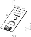
- FIG. 3 is a perspective view of a substrate 30.
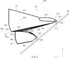
- FIG. 3 is a side view of a substrate 30 and a separator 50.
- FIG. 5 is a top view of a separator 50.
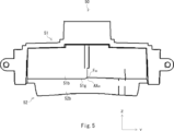
- FIG. 5 is a front view of a separator 50.
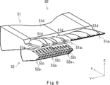
- FIG. 5 is a perspective view of a separator 50.
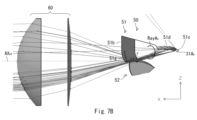
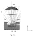
- FIG. FIG. 4 is a diagram (top view) showing the optical path of the light RayA 4 emitted by the low beam light source 31A 4 and the light RayA 1 emitted by the low beam light source 31A 1.
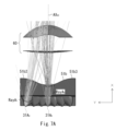
- FIG. 4 is a diagram (side view) showing the optical path of light RayA 4 emitted by the low beam light source 31A 4.
- FIG. This is an example of a partial light distribution pattern P Lo4 for low beam formed by light RayA 4 emitted by light source 31A 4 for low beam.
- P Lo1 to P Lo6 for low beam formed by light emitted by light sources 31A 1 to 31A 6 for low beam.
- P LO formed by superimposing partial light distribution patterns P Lo1 to P Lo6 on each other.
- 5 is a bottom view of a separator 50.
- FIG. It is an enlarged view of the vicinity of the high beam light incident part 52a7 .
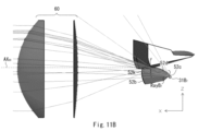
- FIG. 7 is a diagram (bottom view) showing the optical path of the light RayB 7 emitted by the high beam light source 31B 7 and the light RayB 2 emitted by the high beam light source 31B 2.
- FIG. FIG. 7 is a diagram (side view) showing the optical path of the light RayB 7 emitted by the high beam light source 31B 7.
- FIG. This is an example of a partial light distribution pattern PHi7 formed by light RayB7 emitted by the high beam light source 31B7 .
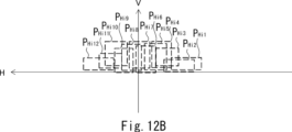
- This is an example of partial light distribution patterns P Hi1 to P Hi12 formed by light emitted from the high beam light sources 31B 1 to 31B 12 .
- FIG. 1 is a longitudinal cross-sectional view of the vehicle lamp 10 taken along a vertical plane including the optical axis AX 60 (reference axis) of the projection lens 60.
- the vehicle lamp 10 of this embodiment is a vehicle headlamp that functions as a low beam or high beam headlamp, and is mounted on both left and right sides of the front end of a vehicle (not shown) such as an automobile. Since the vehicle lights 10 mounted on both the left and right sides have a symmetrical configuration, the vehicle lights 10 mounted on the right side of the front end of the vehicle (the right side when facing the front of the vehicle) will be described below as a representative. .
- the vehicle lamp 10 includes a heat sink 20, a substrate 30 on which a low beam light source 31A and a high beam light source 31B are mounted, a holder 40, a separator 50, and a projection lens 60.
- XYZ axes will be defined.
- the X-axis extends in the vehicle longitudinal direction
- the Y-axis extends in the vehicle width direction
- the Z-axis extends in the vertical direction.
- the heat sink 20 includes a substrate fixing surface 20a to which the substrate 30 is fixed.
- the substrate fixing surface 20a is inclined at an angle ⁇ 1 with respect to the Z axis.
- the angle ⁇ 1 is, for example, 50°.
- metals with high thermal conductivity such as aluminum and copper, alloys thereof, and alloys with low specific gravity such as magnesium are used.
- the heat sink 20 is manufactured by a manufacturing method such as cutting, extrusion, insertion, brazing, die casting, or the like.
- FIG. 2 is a perspective view of the substrate 30.
- the substrate 30 is a metal substrate made of aluminum or the like, and includes a light source mounting surface 30a on which the low beam light sources 31A 1 to 31A 6 and high beam light sources 31B 1 to 31B 12 are mounted, and a back surface 30b on the opposite side.
- a low beam light source 31A 1 to 31A 6 and the high beam light sources 31B 1 to 31B 12 are particularly distinguished, they will be referred to as a low beam light source 31A and a high beam light source 31B.
- the low beam light source 31A and the high beam light source 31B are semiconductor light emitting devices such as LEDs. As shown in FIG. 2, in the present embodiment, six low beam light sources 31A 1 to 31A 6 are arranged in a line in the Y-axis direction at intervals on the upper stage of the board 30 (light source mounting surface 30a). Twelve high-beam light sources 31B 1 to 31B 12 are mounted in the lower row and arranged in a row in the Y-axis direction with intervals between them.
- the low beam light source 31A and the high beam light source 31B each include a light emitting surface.
- the light emitting surface is, for example, a 1 mm square rectangular light emitting surface.
- the low beam light source 31A and the high beam light source 31B are mounted on the substrate 30 (light source mounting surface 30a) with their light emitting surfaces parallel to the light source mounting surface 30a.
- the optical axis AX 31A (see FIGS. 1 and 3) of the low beam light source 31A passes through the center of the light emitting surface and extends in a direction perpendicular to the light emitting surface.
- the optical axis AX 31B (see FIGS. 1 and 3) of the high beam light source 31B passes through the center of the light emitting surface and extends in a direction perpendicular to the light emitting surface.
- the substrate 30 is fixed (for example, fixed with screws) to the heat sink 20 (substrate fixing surface 20a) while being inclined at an angle ⁇ 1 (see FIG. 1) with respect to the Z-axis.
- the back surface 30b on the opposite side of the light source mounting surface 30a contacts the substrate fixing surface 20a of the heat sink 20, so that the substrate 30 is tilted at an angle ⁇ 1 with respect to the Z axis.
- TIM such as thermal grease, thermally conductive sheet, thermally conductive adhesive, etc. is used to increase adhesion between the two and reduce contact thermal resistance.
- Thermal Interface Materials heat conduction materials
- FIG. 3 is a side view of the substrate 30 and separator 50.
- FIG. 4 is a top view of the separator 50.
- the separator 50 is made of silicone resin and includes an upper separator 51 and a lower separator 52, as shown in FIG. Note that the separator 50 may be made of a heat-resistant material and is not limited to silicone resin. For example, the separator 50 may be made of glass.
- the upper separator 51 is arranged above the optical axis AX 60 of the projection lens 60.
- the lower separator 52 is arranged below the optical axis AX 60 of the projection lens 60.
- the optical axis AX 60 of the projection lens 60 extends in the X-axis direction.
- the separator 50 is configured symmetrically with respect to the optical axis AX 60 of the projection lens 60 when viewed from above.
- the upper separator 51 and the lower separator 52 are integrally molded with the lower end of the low beam light output surface 51b of the upper separator 51 and the upper end of the high beam light output surface 52b of the lower separator 52 connected (see FIG. 3). ). Note that the upper separator 51 and the lower separator 52 may be molded separately.
- the separator 50 is constructed such that the low beam light entrance section 51a (low beam light entrance surface 51c) and the high beam light entrance section 52a (high beam light entrance surface 51c)
- the light incident surface 52c), the low beam light source 31A, and the high beam light source 31B are arranged in front of the substrate 30 in a facing state (positioned state) (see FIG. 3).
- the holder 40 includes a light shielding part 41 (see FIG. 1).
- the light blocking section 41 prevents light from the low beam light source 31A that has entered the upper separator 51 from leaking out and does not enter the lower separator 52, and prevents light from the high beam light source 31B that has entered the lower separator 52 from leaking. It is arranged between the upper separator 51 and the lower separator 52 so that the light does not exit and enter the upper separator 51.
- the projection lens 60 is an aspherical lens.
- the projection lens 60 is arranged in front of the separator 50 by fixing the projection lens 60 to the heat sink 20 or the like while positioning the projection lens 60 with respect to the separator 50 .
- the focal point F 60 of the projection lens 60 (see FIGS. 3 and 5) is located between the lower end of the low beam light exit surface 51b of the upper separator 51 and the upper end of the high beam light exit surface 52b of the lower separator 52 (cutoff shape 51g ) is located in
- FIG. 5 is a front view of the separator 50.
- a cut-off shape 51g (Z-shaped stepped portion) is provided.
- the optical length of the upper separator 51 (the optical distance that the light from the low beam light source 31A passes through the inside of the upper separator 51) is the optical length of the lower separator 52 (the optical distance that the light from the high beam light source 31B passes through the inside of the lower separator 52). distance) is longer (see Figure 3).
- FIG. 6 is a perspective view of the separator 50.
- the upper separator 51 includes a low beam light entrance part 51a (51a 1 to 51a 7 ; see FIGS. 3, 4, and 6) arranged on the rear side of the vehicle, and a low beam light exit surface 51b arranged on the front side of the vehicle (see FIGS. 3, 4, and 6). 3)).
- a low beam light entrance part 51a 51a 1 to 51a 7 ; see FIGS. 3, 4, and 6
- a low beam light exit surface 51b arranged on the front side of the vehicle (see FIGS. 3, 4, and 6). 3)).
- the low beam light entrance parts 51a 1 to 51a 7 are particularly distinguished, they will be referred to as low beam light entrance parts 51a.
- the low beam light entrance portions 51a 1 to 51a 7 are arranged in a line in the Y-axis direction.
- the low beam light sources 31A 1 to 31A 6 are The light incident parts 51a 1 to 51a 6 are arranged to face each other.
- the dotted rectangles in FIG. 4 represent the low beam light sources 31A 1 to 31A 6 that are visible through the upper separator 51 (low beam light entrance portions 51a 1 to 51a 6 ).
- the low beam light sources 31A 1 to 31A 6 are connected to the low beam light entrance portions 51a 1 to 51a. 6 , but low beam light incident parts 51a 2 to 51a 7 are arranged facing each other.
- the separator 50 is arranged relative to the optical axis AX 60 of the projection lens 60 when viewed from above.
- the separator 50 (upper separator 51) is mounted on the vehicle lamp 10 mounted on the right side of the front end of the vehicle (right side when facing the front of the vehicle) and on the left side of the front end of the vehicle.
- the vehicle lamp 10 mounted on the left side when facing the front of the vehicle can also be used.
- the low beam light entrance part 51a includes a low beam light entrance surface 51c facing the low beam light source 31A (light emitting surface), and a low beam total reflection surface disposed above the low beam light entrance surface 51c. 51d.
- the low beam light incident surface 51c is, for example, a plane parallel to the light emitting surface of the low beam light source 31A.
- the interval between the low beam light source 31A (light emitting surface) and the low beam light entrance surface 51c is about 2 mm, and the low beam light source 31A is arranged close to the low beam light entrance surface 51c.
- the low beam total reflection surface 51d is configured so that the light from the low beam light source 31A enters from the low beam light incident surface 51c and enters the low beam total reflection surface 51d so as to condense the light near the focal point F60 of the projection lens 60 . It is a total reflection surface that totally reflects the light.
- the low beam total reflection surface 51d has a first focal point F1 51d (see FIG. 3) located near the low beam light source 31A, and a second focal point F2 51d (see FIG. 3) that is the focal point F of the projection lens 60. It is a total reflection surface with an elliptical tone located near 60° .
- the center portion 51b1 of the low beam light exit surface 51b is along the focal plane FP of the projection lens 60 when viewed from above (the same applies to the horizontal section).
- portions 51b2 and 51b3 on both sides of the central portion 51b1 of the low beam light output surface 51b are spaced from the focal plane FP of the projection lens 60 toward the rear of the vehicle.
- the incident angle of light for example, see RayA 1 in FIG. 7A
- the incident angle of light that enters the portions 51b2 and 51b3 on both sides of the central portion 51b1 of the low beam light exit surface 51b becomes small.
- FIG. 7A is a diagram (top view) showing the optical paths of the light RayA 4 emitted by the low beam light source 31A 4 and the light RayA 1 emitted by the low beam light source 31A 1 .
- the low beam light exit surface 51b extends upward from the lower end of the low beam light exit surface 51b via an inclined portion 51g that slopes toward the front of the vehicle. ing.
- the incident angle of light for example, see Ray A 4 in FIG. 7B
- the incident angle of light that enters the vicinity of the lower end (slope portion 51g) of the low beam light exit surface 51b becomes small. This suppresses the occurrence of Fresnel reflection (Fresnel loss) or total reflection near the lower end (slanted part 51g) of the light exit surface 51b for low beam. Light can also be efficiently extracted from the portion 51g).
- FIG. 7B is a diagram (side view) showing the optical path of the light RayA 4 emitted by the low beam light source 31A 4 .
- the low beam light exit surface 51b be disposed slightly toward the rear of the vehicle from the focal point F60 of the projection lens 60 . In this way, it is possible to prevent dust and the like adhering to the vicinity of the cutoff shape 51g from being projected onto the low beam light distribution pattern.
- a lower surface 51e is provided between the lower end of the low beam light exit surface 51b and the low beam light entrance surface 51c. Further, an upper surface 51f is provided between the upper end portion of the low beam light output surface 51b and the low beam total reflection surface 51d.
- FIG. 8A is an example of a partial light distribution pattern P Lo4 for low beam formed by light Ray A 4 emitted by light source 31A 4 for low beam.
- the external shape of the partial light distribution pattern P Lo4 in FIG. 8A is an isoluminous line (representing 625 cd).
- FIG. 8B is an example of partial light distribution patterns P Lo1 to P Lo6 for low beam formed by the light emitted by the light sources 31A 1 to 31A 6 for low beam. Note that in reality, the upper and lower edges of the partial light distribution patterns P Lo1 to P Lo6 roughly match, but it is difficult to understand if they are drawn in a matched state, so in FIG. 8B, the partial light distribution patterns P Lo1 to P Lo6 are P Lo6 is drawn shifted up and down.
- FIG. 8C shows an example of a low beam light distribution pattern P LO formed by overlapping the partial light distribution patterns P Lo1 to P Lo6 with each other. Note that each of the light distribution patterns shown in FIGS. 8A to 8C is formed on a virtual vertical screen (located approximately 25 m in front of the front of the vehicle) directly facing the front of the vehicle.
- the low beam light distribution pattern PLO shown in FIG. 8C is formed as follows.
- the low beam light sources 31A 1 to 31A 6 are turned on.
- the light RayA 4 (see FIGS. 7A and 7B) emitted by the low beam light source 31A 4 enters from the low beam light entrance surface 51c that the low beam light source 31A 4 faces, and enters the low beam total reflection surface 51d.
- the light is totally reflected and exits from the low beam light exit surface 51b.
- a light intensity distribution corresponding to the partial light distribution pattern P Lo4 shown in FIG. 8A is formed near the focal plane FP of the projection lens 60.
- the light intensity distribution corresponding to the partial light distribution pattern P Lo4 is invertedly projected forward by the projection lens 60, thereby forming the partial light distribution pattern P Lo4 as shown in FIG. 8A.
- the light emitted by the low beam light sources 31A 1 to 31A 3 , 31A 5 , 31A 6 other than the low beam light source 31A 4 also differs from the light emitted by the low beam light sources 31A 1 to 31A 3 , 31A 5 , 31A 6 that are opposed to each other.
- a light intensity distribution corresponding to the partial light distribution patterns P Lo1 to P Lo6 shown in FIG. 8B is formed near the focal plane FP of the projection lens 60.
- a low beam light distribution pattern P Lo is formed.
- the upper edge of the low beam light distribution pattern P Lo has a cut-off shape 51g (see FIG. 5)).
- the partial light distribution pattern for low beams (for example, see P Lo4 shown in FIG. 8A) is wider in the horizontal direction than the partial light distribution pattern for high beams (for example, see P Hi7 shown in FIG. 12A), which will be described later.
- the optical length of the upper separator 51 (the optical distance that the light from the low beam light source 31A passes through the inside of the upper separator 51) is different from the optical length of the lower separator 52 (the optical distance that the light from the high beam light source 31B passes through the inside of the lower separator 52). This is due to the fact that the optical distance traveled is longer (see FIG. 3).
- the partial light distribution patterns P Lo1 to P Lo6 for low beam are formed in a state in which they are overlapped with each other in the horizontal direction (see FIG. 8B), the low beam light can be evenly spread in the horizontal direction by using a smaller number of low beam light sources 31A.
- a light distribution pattern P Lo can be formed.
- the lower separator 52 includes a high beam light entrance part 52a (52a 1 to 52a 13 , see FIGS. 3 and 6) arranged on the rear side of the vehicle, and a high beam light exit surface 52b arranged on the front side of the vehicle.
- a high beam light incident section 52a 1 to 52a 13 are particularly distinguished, they will be referred to as high beam light incident sections 52a.
- the vehicle rear side portion of the lower separator 52 is divided by dividing grooves 52j (plurality) penetrating in the Z-axis direction, thereby forming strip-shaped high beam light entrance portions 52a 1 to 52a 13 . It consists of
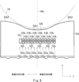
- FIG. 9 is a bottom view of the separator 50.
- the high beam light incident parts 52a 1 to 52a 13 are arranged in a line in the Y-axis direction.
- the high beam light sources 31B 1 to 31B 12 are The light incident portions 52a 1 to 52a 12 are arranged to face each other.
- the high beam light sources 31B 1 to 31B 12 are connected to the high beam light entrance portions 52a 1 to 52a. 12 , but high beam light incident parts 52a 2 to 52a 13 are arranged facing each other.
- the separator 50 is arranged relative to the optical axis AX 60 of the projection lens 60 when viewed from above.
- the separator 50 lower separator 52
- the separator 50 is mounted on the vehicle lamp 10 mounted on the right side of the front end of the vehicle (right side when facing the front of the vehicle) and on the left side of the front end of the vehicle.
- the vehicle lamp 10 mounted on the left side when facing the front of the vehicle can also be used.
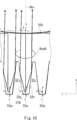
- the high beam light entrance section 52a includes a high beam light entrance surface 52c facing the high beam light source 31B (light emitting surface), and a high beam total reflection surface disposed above the high beam light entrance surface 52c. 52d. Further, as shown in FIG. 10, the high beam light incident section 52a includes a pair of side surfaces 52g and 52h. FIG. 10 is an enlarged view of the vicinity of the high beam light incident section 52a7 .
- the high beam light incident surface 52c is, for example, a plane parallel to the light emitting surface of the high beam light source 31B.
- the interval between the high beam light source 31B (light emitting surface) and the high beam light incident surface 52c is about 2 mm, and the high beam light source 31B is arranged close to the high beam light incident surface 52c.
- the high beam total reflection surface 52d allows light from the high beam light source 31B to enter from the high beam light incident surface 52c and enter the high beam total reflection surface 52d so as to condense the light near the focal point F60 of the projection lens 60 . It is a total reflection surface that totally reflects the light.
- the high beam total reflection surface 52d is a curved reflection surface.
- the high beam total reflection surface 52d may be an elliptical total reflection surface with a first focal point located near the high beam light source 31B and a second focal point located near the focal point F60 of the projection lens 60.
- the center portion 52b1 of the high beam light output surface 52b is along the focal plane FP of the projection lens 60 when viewed from above (the same applies to the horizontal section).
- portions 52b2 and 52b3 on both sides of the central portion 52b1 of the high beam light output surface 52b are spaced from the focal plane FP of the projection lens 60 toward the rear of the vehicle.
- the angle of incidence of light that enters the portions 52b2 and 52b3 on both sides of the central portion 52b1 of the high beam light output surface 52b becomes small.
- FIG. 11A is a diagram (bottom view) showing the optical path of the light RayB 7 emitted by the high beam light source 31B 7 and the light RayB 2 emitted by the high beam light source 31B 2 .
- the high beam light emitting surface 52b extends downward from the upper end of the high beam light emitting surface 52b via an inclined portion 52k that slopes toward the front of the vehicle. ing.
- the angle of incidence of light for example, see RayB 7 in FIG. 11B
- the light can also be efficiently extracted from the portion 52k).
- FIG. 11B is a diagram (side view) showing the optical path of the light RayB 7 emitted by the high beam light source 31B 7.
- a lower surface 52e is provided between the lower end of the high beam light exit surface 52b and the high beam light entrance surface 52c.
- an upper surface 52f is provided between the upper end portion of the high beam light output surface 52b and the high beam total reflection surface 52d.
- FIG. 12A is an example of a partial light distribution pattern PHi7 formed by the light RayB7 emitted by the high beam light source 31B7 .
- the external shape of the partial light distribution pattern PHi7 in FIG. 12A is an isoluminous line (representing 625 cd).
- FIG. 12B is an example of partial light distribution patterns P Hi1 to P Hi12 formed by light emitted by the high beam light sources 31B 1 to 31B 12 . Note that in reality, the lower edges of the partial light distribution patterns P Hi1 to P Hi12 roughly match, but it is difficult to understand if they are drawn in a matched state, so in FIG. 12B, the lower edges of the partial light distribution patterns P Hi1 to P Hi12 are It is drawn shifted up and down. FIG.
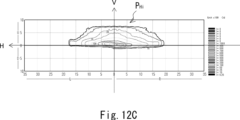
- each of the light distribution patterns shown in FIGS. 12A to 12C is formed on a virtual vertical screen (located approximately 25 m in front of the front of the vehicle) directly facing the front of the vehicle.
- the high beam light distribution pattern PHi shown in FIG. 12C is formed as follows.
- the high beam light sources 31B 1 to 31B 12 are turned on.
- the light RayB 7 (see FIGS. 11A and 11B) emitted by the high beam light source 31B 7 enters from the high beam light entrance surface 52c that the high beam light source 31B 7 faces, and some of the light is for the high beam.
- the light is totally reflected by the total reflection surface 52d, and some of the other light is totally reflected by the pair of side surfaces 52g and 52h (see FIG. 10), and then exits from the high beam light output surface 52b.
- some light directly exits from the high beam output surface 52b without being totally reflected by the high beam total reflection surface 52d, the pair of side surfaces 52g, 52h, and the like.
- a light intensity distribution corresponding to the partial light distribution pattern P Hi7 shown in FIG. 12A is formed near the focal plane FP of the projection lens 60.
- the light intensity distribution corresponding to this partial light distribution pattern P Hi7 is invertedly projected forward by the projection lens 60, thereby forming a partial light distribution pattern P Hi7 as shown in FIG. 12A.
- the light emitted by the high beam light sources 31B 1 to 31B 6 and 31B 8 to 31B 12 other than the high beam light source 31B 7 also differs from the light emitted by the high beam light sources 31B 1 to 31B 6 and 31B 8 to 31B 12 that are opposed to each other.
- the light intensity distribution corresponding to the partial light distribution patterns P Hi1 to P Hi12 (see FIG. 12B) is invertedly projected forward by the projection lens 60, so that the high beam light distribution pattern P Hi is created as shown in FIG. 12C. It is formed.
- the lower edge of the high beam light distribution pattern P Hi has a cut-off shape 51g (see FIG. 5)).
- the partial light distribution pattern for high beam (for example, see P Hi7 shown in FIG. 12A) is narrower in the horizontal direction than the partial light distribution pattern for low beam (for example, see P Lo4 shown in FIG. 8A), This makes it suitable for the light distribution pattern for variable beam system (variable light distribution type headlamps).
- the optical length of the upper separator 51 (the optical distance that the light from the low beam light source 31A passes through the inside of the upper separator 51) is different from the optical length of the lower separator 52 (the optical distance that the light from the high beam light source 31B passes through the inside of the lower separator 52). This is due to the fact that the optical distance traveled is longer (see FIG. 3).
- the partial light distribution patterns P Hi1 to P Hi12 for high beam are brighter than the partial light distribution patterns P Lo1 to P Lo6 for low beam (see FIG. 8B).
- the lower separator 52 includes a rectangular high-beam light entrance portion 52a (a pair of side surfaces 52g and 52h) that controls the light from being diffused in the horizontal direction.
- the present embodiment even if the number of low beam light sources is reduced, uneven light distribution can be suppressed from occurring in the low beam light distribution pattern, and the high beam light distribution pattern can be suppressed. It is possible to provide a vehicle lamp whose distributed light pattern does not spread in the horizontal direction (as a result, the luminous intensity required for a partial light distribution pattern for high beams can be satisfied and the ADB function can be realized). This is because the optical length of the upper separator 51 is longer than the optical length of the lower separator 52.
- the optical length of the upper separator 51 can be increased without increasing the optical length of the lower separator 52, so that the optical length of the upper separator 51 can be made longer than that of the lower separator 52 as described above. Even if the length is longer than the optical length, the high beam partial light distribution patterns P Hi1 to P Hi12 do not expand in the horizontal direction. As a result, even if the number of low beam light sources is reduced, the luminous intensity required for the high beam partial light distribution pattern can be satisfied and the ADB function can be realized.
- the light from the low beam light source 31A that is totally reflected by the low beam total reflection surface 51d is smaller than the reflection angle of the light from the high beam light source 31B that is totally reflected by the high beam total reflection surface 52d.
- the angle of reflection is more acute.
- the amount of light that is totally reflected is larger on the low beam total reflection surface 51d. Therefore, the optical length of the upper separator 51 (the optical distance through which the light from the low beam light source 31A passes through the upper separator 51) can be further increased.
- the optical length of the upper separator 51 (the optical distance that the light from the low beam light source 31A passes through the upper separator 51) is the optical length of the lower separator 52 (the optical distance that the light from the high beam light source 31B passes through).
- the low beam light entrance part 51a and the high beam light entrance part 52a may be molded from a heat-resistant material, and the other parts may be molded from a non-heat-resistant material (for example, acrylic or polycarbonate).
- the angle ⁇ 1 may be smaller than 50°.
- the number of low beam light sources 31A may be increased.
- the angle ⁇ 1 may be set to 40°, seven low beam light sources 31A may be used.
- the angle ⁇ 1 may be larger than 50°. In this way, the number of low beam light sources 31A can be further reduced.
- the low beam light entrance surface 51c and the high beam light entrance surface 52c are flat (substantially flat), but the invention is not limited to this.
- the low beam light incident surface 51c (and the high beam light incident surface 52c) may be a convex surface (or a concave surface) that is convex toward the low beam light source 31A (high beam light source 31B). It's okay.
- FIG. 13 is an enlarged view (modified example) of the vicinity of the high beam light entrance section 52a7 .
- both sides of the high beam light incident part 52a 7 are arranged in the center so that the light from the high beam light source 31B that is totally reflected by the pair of side surfaces 52g and 52h is directed toward the optical axis AX 60 .
- the high-beam light entrance portions 52a (for example, the high-beam light entrance portions 52a 6 and 52a 8 ) may be arranged in an inclined state. In this way, it is possible to suppress Fresnel reflection (Fresnel loss) or total reflection from occurring on the high beam light exit surface 52b.
Landscapes
- Engineering & Computer Science (AREA)
- General Engineering & Computer Science (AREA)
- Physics & Mathematics (AREA)
- Microelectronics & Electronic Packaging (AREA)
- Optics & Photonics (AREA)
- Mechanical Engineering (AREA)
- Non-Portable Lighting Devices Or Systems Thereof (AREA)
Priority Applications (1)
| Application Number | Priority Date | Filing Date | Title |
|---|---|---|---|
| US18/847,083 US12522128B2 (en) | 2022-03-14 | 2023-03-09 | Vehicle lamp |
Applications Claiming Priority (2)
| Application Number | Priority Date | Filing Date | Title |
|---|---|---|---|
| JP2022-039348 | 2022-03-14 | ||
| JP2022039348A JP7749496B2 (ja) | 2022-03-14 | 2022-03-14 | 車両用灯具 |
Publications (1)
| Publication Number | Publication Date |
|---|---|
| WO2023176671A1 true WO2023176671A1 (ja) | 2023-09-21 |
Family
ID=88023271
Family Applications (1)
| Application Number | Title | Priority Date | Filing Date |
|---|---|---|---|
| PCT/JP2023/008999 Ceased WO2023176671A1 (ja) | 2022-03-14 | 2023-03-09 | 車両用灯具 |
Country Status (3)
| Country | Link |
|---|---|
| US (1) | US12522128B2 (cg-RX-API-DMAC7.html) |
| JP (1) | JP7749496B2 (cg-RX-API-DMAC7.html) |
| WO (1) | WO2023176671A1 (cg-RX-API-DMAC7.html) |
Families Citing this family (2)
| Publication number | Priority date | Publication date | Assignee | Title |
|---|---|---|---|---|
| JP2026114462A (ja) * | 2024-12-26 | 2026-07-08 | 市光工業株式会社 | 車両用灯具 |
| WO2026164026A1 (ja) * | 2025-01-31 | 2026-08-06 | 市光工業株式会社 | 車両用灯具 |
Citations (2)
| Publication number | Priority date | Publication date | Assignee | Title |
|---|---|---|---|---|
| JP2021111446A (ja) * | 2020-01-06 | 2021-08-02 | 市光工業株式会社 | 車両用灯具 |
| JP2022517606A (ja) * | 2019-01-29 | 2022-03-09 | ▲華▼域▲視▼▲覺▼科技(上▲海▼)有限公司 | 車両ランプ照明モジュール、車両ランプ及び車両 |
Family Cites Families (5)
| Publication number | Priority date | Publication date | Assignee | Title |
|---|---|---|---|---|
| DE102012203929B3 (de) * | 2012-03-13 | 2013-09-19 | Automotive Lighting Reutlingen Gmbh | Lichtmodul einer Beleuchtungseinrichtung einesKraftfahrzeugs |
| FR3056688B1 (fr) * | 2016-09-26 | 2018-11-02 | Valeo Vision | Module d'eclairage bi-fonction en materiau transparent |
| JP7046730B2 (ja) | 2018-06-21 | 2022-04-04 | スタンレー電気株式会社 | 車両用灯具 |
| US11994267B2 (en) * | 2020-07-06 | 2024-05-28 | Koito Manufacturing Co., Ltd. | Vehicle lamp |
| JP7530281B2 (ja) * | 2020-12-15 | 2024-08-07 | 株式会社小糸製作所 | 灯具ユニット |
-
2022
- 2022-03-14 JP JP2022039348A patent/JP7749496B2/ja active Active
-
2023
- 2023-03-09 WO PCT/JP2023/008999 patent/WO2023176671A1/ja not_active Ceased
- 2023-03-09 US US18/847,083 patent/US12522128B2/en active Active
Patent Citations (2)
| Publication number | Priority date | Publication date | Assignee | Title |
|---|---|---|---|---|
| JP2022517606A (ja) * | 2019-01-29 | 2022-03-09 | ▲華▼域▲視▼▲覺▼科技(上▲海▼)有限公司 | 車両ランプ照明モジュール、車両ランプ及び車両 |
| JP2021111446A (ja) * | 2020-01-06 | 2021-08-02 | 市光工業株式会社 | 車両用灯具 |
Also Published As
| Publication number | Publication date |
|---|---|
| US20250222855A1 (en) | 2025-07-10 |
| JP7749496B2 (ja) | 2025-10-06 |
| US12522128B2 (en) | 2026-01-13 |
| JP2023134029A (ja) | 2023-09-27 |
Similar Documents
| Publication | Publication Date | Title |
|---|---|---|
| JP6864633B2 (ja) | 車両用灯具及び基板 | |
| CN112781004A (zh) | 车辆用灯具 | |
| US11971147B2 (en) | Vehicle light guide and vehicle headlight | |
| JP7530281B2 (ja) | 灯具ユニット | |
| CN114688494A (zh) | 车辆用灯具 | |
| JP7540299B2 (ja) | 車両用前照灯 | |
| US20180272921A1 (en) | Light-projecting device and light cut-off structure thereof | |
| US12522128B2 (en) | Vehicle lamp | |
| JP6582524B2 (ja) | 車両用灯具 | |
| JP7517888B2 (ja) | 車両用灯具 | |
| JP7536543B2 (ja) | 車両用灯具 | |
| WO2017135435A1 (ja) | 車両用灯具 | |
| WO2023282238A1 (ja) | 車両用灯具 | |
| JP7028618B2 (ja) | 車両用灯具 | |
| US11293617B2 (en) | Vehicular lighting fixture | |
| CN110630974B (zh) | 车辆用灯具 | |
| JP2019220404A (ja) | 車両用灯具 | |
| CN116457610B (zh) | 车辆用灯具 | |
| JP7628050B2 (ja) | 車両用灯具 | |
| JP7131250B2 (ja) | 車両用灯具 | |
| JP2026054687A (ja) | 車両用灯具 | |
| JP2018097914A (ja) | 前照灯モジュール | |
| JP2022175633A (ja) | 灯具ユニット | |
| JP2026059081A (ja) | 車両用灯具 | |
| JP2024075193A (ja) | 照明装置 |
Legal Events
| Date | Code | Title | Description |
|---|---|---|---|
| 121 | Ep: the epo has been informed by wipo that ep was designated in this application |
Ref document number: 23770627 Country of ref document: EP Kind code of ref document: A1 |
|
| WWE | Wipo information: entry into national phase |
Ref document number: 18847083 Country of ref document: US |
|
| NENP | Non-entry into the national phase |
Ref country code: DE |
|
| 122 | Ep: pct application non-entry in european phase |
Ref document number: 23770627 Country of ref document: EP Kind code of ref document: A1 |
|
| WWP | Wipo information: published in national office |
Ref document number: 18847083 Country of ref document: US |
|
| WWG | Wipo information: grant in national office |
Ref document number: 18847083 Country of ref document: US |