WO2023176523A1 - Dispositif de communication et procédé de communication - Google Patents
Dispositif de communication et procédé de communication Download PDFInfo
- Publication number
- WO2023176523A1 WO2023176523A1 PCT/JP2023/008134 JP2023008134W WO2023176523A1 WO 2023176523 A1 WO2023176523 A1 WO 2023176523A1 JP 2023008134 W JP2023008134 W JP 2023008134W WO 2023176523 A1 WO2023176523 A1 WO 2023176523A1
- Authority
- WO
- WIPO (PCT)
- Prior art keywords
- ndp
- information
- transmission
- terminal
- type
- Prior art date
Links
Images


Classifications
-
- H—ELECTRICITY
- H04—ELECTRIC COMMUNICATION TECHNIQUE
- H04W—WIRELESS COMMUNICATION NETWORKS
- H04W28/00—Network traffic management; Network resource management
- H04W28/02—Traffic management, e.g. flow control or congestion control
- H04W28/06—Optimizing the usage of the radio link, e.g. header compression, information sizing, discarding information
-
- H—ELECTRICITY
- H04—ELECTRIC COMMUNICATION TECHNIQUE
- H04W—WIRELESS COMMUNICATION NETWORKS
- H04W72/00—Local resource management
- H04W72/04—Wireless resource allocation
- H04W72/044—Wireless resource allocation based on the type of the allocated resource
- H04W72/0453—Resources in frequency domain, e.g. a carrier in FDMA
-
- H—ELECTRICITY
- H04—ELECTRIC COMMUNICATION TECHNIQUE
- H04W—WIRELESS COMMUNICATION NETWORKS
- H04W72/00—Local resource management
- H04W72/20—Control channels or signalling for resource management
- H04W72/23—Control channels or signalling for resource management in the downlink direction of a wireless link, i.e. towards a terminal
-
- H—ELECTRICITY
- H04—ELECTRIC COMMUNICATION TECHNIQUE
- H04W—WIRELESS COMMUNICATION NETWORKS
- H04W84/00—Network topologies
- H04W84/02—Hierarchically pre-organised networks, e.g. paging networks, cellular networks, WLAN [Wireless Local Area Network] or WLL [Wireless Local Loop]
- H04W84/10—Small scale networks; Flat hierarchical networks
- H04W84/12—WLAN [Wireless Local Area Networks]
Definitions
- the present disclosure relates to a communication device and a communication method.
- IEEE 802.11be for next-generation wireless local area networks (LAN), which is the successor standard to the standard IEEE 802.11ax (hereinafter also referred to as "11ax”).
- LAN next-generation wireless local area networks
- 11ax also referred to as "11ax”
- HE High Efficiency
- EHT Extremely High Throughput
- studies are underway on a successor standard to 11be that aims to further reduce latency and improve throughput (see, for example, Non-Patent Document 1).
- IEEE P802.11-22/0032r0 “Thoughts on Next Generation After 802.11be” IEEE 802.11-21/1333r4, “CC36 CR for Trigger frame on Common Info field format” IEEE 802.11-21/0259r4, “Proposed Draft Specification for Trigger frame for EHT” IEEE P802.11ax/D8.0 IEEE 802.11-20/1672r2, “UL Beamforming for TB PPDUs in 11be”
- one communication device e.g., a terminal transmits a response signal in response to a control signal instruction received from another communication device (e.g., an access point (AP)).
- AP access point
- Non-limiting embodiments of the present disclosure contribute to providing a communication device and a communication method that can generate a control signal that appropriately indicates the type of response signal.
- a communication device sets first information indicating a type of response signal in a first field, and sets second information corresponding to the first information in a second field. and a transmitting circuit that transmits the control signal.
- a control signal that appropriately indicates the type of response signal can be generated.
- a block diagram showing a partial configuration example of an AP according to an embodiment of the present disclosure A block diagram showing a partial configuration example of a terminal according to an embodiment of the present disclosure
- the IEEE is proceeding with consideration of 11be, which is a successor standard to 11ax, and is also proceeding with consideration of a successor standard to 11be (see, for example, Non-Patent Document 1).
- the successor standard of 11be will be referred to as EHTplus.
- HE stipulated the introduction of upstream OFDMA (Orthogonal Frequency-Division Multiple Access).
- An access point also called a “base station”
- AP sends a control signal (hereinafter referred to as a "trigger frame") that instructs the transmission of uplink OFDMA signals to multiple frames accommodated by the AP.
- STA Send to a terminal (STA: Station. Also called “non-AP STA”).
- STA Station.
- non-AP STA a terminal that supports HE and/or a terminal that complies with HE may be referred to as an HE terminal.
- EHT it has also been agreed to reuse the HE Trigger frame as a control signal that instructs multiple terminals to transmit upstream OFDMA signals (for example, see Non-Patent Document 2).
- a terminal that supports EHT and/or a terminal that complies with EHT may be referred to as an EHT terminal.
- EHTplus it is possible to reuse the Trigger frame as a control signal that instructs the transmission of uplink signals to multiple terminals.
- a terminal that supports EHTplus and/or a terminal that complies with EHTplus may be referred to as an EHTplus terminal.
- control signal instructing multiple terminals will be described below as an example, the present disclosure is not limited thereto.
- the control signal may be directed to one terminal instead of multiple terminals.
- multiple terminals each transmit a signal (response signal) based on a control signal
- the present disclosure is not limited to this.
- the number of terminals that transmit the response signal based on the control signal may be one.
- the Trigger frame includes a Common Info field, a User Info List, and a Special User Info field (see, for example, Non-Patent Documents 2 and 3).
- the Common Info field contains information common to multiple terminals performing OFDMA multiplexing.
- User Info List includes multiple User Info fields.
- the User Info field contains information specific to each device.
- the Special User Info field contains common information for EHT terminals.
- the Special User Info field may include common information for EHTplus terminals.
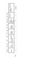
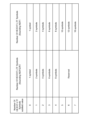
- FIG. 1 is a diagram showing an example of the Common Info field (Common Info field, EHT variant).
- FIG. 2 is a diagram illustrating an example of a User Info field (User Info field, EHT variant).
- FIG. 3 is a diagram showing an example of the Special User Info field.
- FIG. 1, FIG. 2, and FIG. 3 show configuration examples under consideration for EHT (see, for example, Non-Patent Documents 2 and 3).
- a Special User Info field When a Trigger frame is sent for an EHT terminal, a Special User Info field may be provided.
- the Trigger Type subfield of the Common Info field includes information that indicates the type of Trigger frame.
- the type of Trigger frame may be the type of signal that the AP transmits to the terminal.
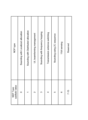
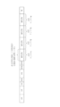
- FIG. 4 is a diagram showing an example of Trigger Type.
- FIG. 4 shows, in a table format, the correspondence between the value of the Trigger Type subfield (Trigger Type subfield value in FIG. 4) and the type of Trigger frame (Trigger frame variant in FIG. 4) indicated by that value.
- the types shown in FIG. 4 are defined as Trigger Types (Non-Patent Document 4).
- the Trigger Dependent Common Info subfield (for example, see FIG. 1) includes common information that depends on the Trigger Type.
- the Trigger Type subfield indicates that the Trigger Type is NDP Feedback Report Poll (NFRP).
- NFRP NDP Feedback Report Poll
- FIG. 5 is a diagram showing an example of the User Info field.
- the Trigger Type is NDP Feedback Report Poll (NFRP)
- the format of the User Info field has the configuration illustrated in FIG. 5 (for example, see Non-Patent Document 4). Note that, below, a Trigger frame whose Trigger Type is set to NFRP may be described as an NFRP Trigger frame.
- the AP can notify whether the terminal holds data to be transmitted on the uplink through a response signal to the Trigger frame. For example, when a terminal receives an NFRP Trigger frame, it may notify the AP of information indicating whether the terminal holds data to be transmitted on the uplink using a response signal to the NFRP Trigger frame.
- NDP nuclear data packet
- NDP is an example of a signal that does not include data (or a signal that is not accompanied by data), and is an example of a response signal to the Trigger frame. Note that when spatial multiplexing is applied, up to 36 terminals may transmit an NDP that does not include data as a response signal to the NFRP Trigger frame.
- transmitting NDP may be referred to as NDP transmission
- receiving NDP may be referred to as NDP reception
- a signal including NDP may be described as an NDP signal
- a received NDP signal may be described as an NDP received signal.
- HE-LTF High Efficiency-long training field
- EHTLTF Extremely Transmit NDP with High Throughput long training field
- NDP transmission has various uses, so when instructing a terminal to send NDP from an AP, it is necessary to appropriately instruct NDP transmission according to the use.
- the AP determines the purpose of NDP transmission, generates a control signal (Trigger frame) according to the determined purpose of NDP transmission, and transmits the control signal to the terminal.
- the terminal performs NDP transmission for the specified purpose based on the control signal.
- NDP transmission includes, for example, in addition to the Resource request use introduced in HE, channel quality estimation (Sounding) use for MIMO (multiple-input and multiple-output) uplink and/or downlink transmit beamforming. , includes the use of channel quality estimation (sounding) of a predetermined band for uplink adaptation. Further, the application of NDP transmission may include the application of reception beamforming control and the application of transmission antenna switching. Channel quality estimation may be replaced by channel quality measurements.
- the AP calculates the frequency response of the uplink channel from the NDP received signal, performs processing such as singular value decomposition on the frequency response, and converts it into an uplink data signal. Calculate the transmit precoding matrix to be applied. The AP notifies the terminal of the calculated precoding matrix. The terminal applies the notified precoding matrix to data transmission after receiving the notification, thereby improving uplink throughput performance.
- the AP estimates the frequency response of the downlink channel from the NDP received signal by using the reversibility of uplink and downlink of the radio propagation path in TDD (time division duplex). Then, the AP calculates a transmission precoding matrix to be applied to the downlink data signal. The AP improves downlink throughput performance by applying the calculated precoding matrix during data transmission after calculating the transmission precoding matrix.
- the AP calculates uplink channel reception quality (for example, SINR (Signal-to-Interference plus Noise Ratio)) from the NDP received signal. Based on the calculated reception quality, the AP determines the allocated band (e.g., RU (resource unit) number), number of streams, MCS (modulation and coding scheme) (e.g., data modulation method, and link adaptation information such as coding rate) and transmission power. The AP notifies the terminal of the calculated link adaptation information, and the terminal applies the notified link adaptation information to data transmission, thereby improving uplink throughput performance.
- SINR Signal-to-Interference plus Noise Ratio
- the AP receives the NDP reception signal using multiple different reception analog beams, and calculates reception quality for each beam.
- the AP determines the reception analog beam that provides the best reception quality for each terminal, and then applies the best reception analog beam when receiving data from each terminal after the determination, thereby improving uplink throughput performance.
- the AP calculates the reception quality of NDP reception signals transmitted from multiple different transmission antennas.
- the AP determines the transmitting antenna that provides the best reception quality for each terminal, and then instructs each terminal to apply the best transmitting antenna when transmitting data to each terminal, thereby increasing the uplink throughput. Performance can be improved.
- the transmission antenna switching assumes that terminals with different numbers of transmitting antennas and receiving antennas that can be processed simultaneously switch antennas in order to estimate downlink channel quality for downlink MIMO transmission.
- a terminal with a different number of transmitting antennas and a different number of receiving antennas that can be processed simultaneously is, for example, a terminal with a smaller number of transmitting antennas.
- the configuration of the number of transmitting antennas and the number of receiving antennas may be defined as capability information of the terminal. Then, by the terminal transmitting Capability information to the AP, the configuration of the number of transmitting antennas and the number of receiving antennas of the terminal may be shared in advance between the terminal and the AP.
- FIG. 6 is a diagram showing transmission antenna switching for a terminal with one transmission and four receptions. Note that 1 transmission indicates that the number of transmitting antennas is 1, and 4 reception indicates that the number of receiving antennas is 4. Below, 1 transmission and 4 receptions will be described as 1T4R.
- a terminal with fewer transmitting antennas than receiving antennas temporally switches the transmitting antenna that performs NDP transmission. This allows the terminal to select the transmission antenna with the best uplink throughput performance. Furthermore, in an environment such as TDD where reversibility of downlink and uplink channel characteristics can be assumed, a terminal with fewer transmitting antennas than receiving antennas temporally switches the transmitting antenna for transmitting NDP.
- the AP can estimate the frequency response from the received signal of each NDP and calculate the transmission precoding matrix to be applied to downlink data transmission, improving downlink throughput performance.
- NDP transmission has various uses, and it is desirable to apply an appropriate transmission method depending on the use.
- each of the multiple terminals may notify information regarding the presence or absence of data through NDP transmission. Therefore, it is sufficient that the NDP signal transmitted by the terminal is transmitted using relatively sparsely allocated tone allocations, and does not need to be transmitted over a wide band (for example, with densely allocated tone allocations).
- NDP transmission is used for quality estimation (sounding) for MIMO use
- the NDP signal transmitted by the terminal in order to obtain beamforming gain and/or scheduling gain, the NDP signal transmitted by the terminal must be distributed over a wide band and with densely arranged tone assignments. It is hoped that the information will be sent in . Desired estimation accuracy can be obtained by densely allocating tone.
- NDP transmission without accompanying data becomes overhead for system throughput performance
- NDP transmission from multiple terminals is efficiently controlled.
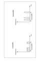
- FIG. 7 is a diagram showing an example of NDP transmission between two terminals.
- FIG. 7 shows an example of signals transmitted by the AP, terminal 1, and terminal 2.
- the horizontal axes of the AP, terminal 1, and terminal 2 in FIG. 7 indicate time axes.
- terminal 1 and terminal 2 send NDP.
- the AP instructs terminal 1 and terminal 2 to transmit NDP in the Sounding band that includes RU1 and RU2
- terminal 1 and terminal 2 send NDP.
- control using multiple trigger frames two in FIG. 7 is required, which increases overhead.
- a trigger frame is required that efficiently (with little overhead) instructs NDP transmission using the transmission method necessary to obtain the desired effect.
- the AP uses a Trigger frame (an example of a control signal) to instruct the terminal to perform NDP transmission determined from among multiple types of NDP transmission.
- a Trigger frame an example of a control signal
- Multiple types of NDP transmission may be associated with multiple uses of NDP.
- multiple types of NDP transmission may correspond to multiple NDP transmission methods.
- There are multiple ways to transmit NDP including the band for transmitting NDP, the method of allocating the signals (for example, symbols) that make up NDP, the procedure for transmitting NDP, the switching of the antenna for transmitting NDP, the information indicated by NDP, etc. may include methods in which at least one of the methods is different from each other.
- “multiple types of NDP transmission” may be replaced with "multiple types of NDP”.
- each type included in multiple types of NDP may be referred to as an NDP type.
- information indicating the NDP type may be described as NDP type information.
- the NDP transmission instruction may be understood as an instruction for the NDP to be transmitted or an instruction for the NDP type.
- instructing NDP transmission may correspond to notifying information instructing NDP transmission or providing information instructing NDP transmission.
- Information instructing NDP transmission may be replaced with information indicating NDP transmission.
- the information indicating the NDP type may be replaced with information indicating the NDP type.
- the wireless communication system may include, for example, AP 100 and terminal 200.
- the AP 100 may have the functions of both Sharing AP and Shared AP, or it may have either one of the functions.
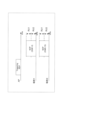
- FIG. 8A is a block diagram illustrating a partial configuration example of the AP 100 according to an embodiment of the present disclosure.
- FIG. 8B is a block diagram showing a partial configuration example of the terminal 200.
- the AP 100 shown in FIG. 8A is an example of a communication device.
- the control unit 111 (corresponding to a control circuit) sets first information (for example, NDP type information) indicating the type of response signal (for example, NDP) in the first field, and A control signal (for example, Trigger frame) is generated in which second information corresponding to the first information is set in the second field.
- the wireless transmitter/receiver 108 (corresponding to a transmitter circuit, for example) transmits a control signal.
- the terminal 200 shown in FIG. 8B is an example of a communication device.
- a wireless transmitter/receiver 201 receives a control signal (e.g., Trigger frame).
- the control unit 210 (for example, corresponding to a control circuit) generates a response signal (for example, NDP) based on the first information included in the first field and the second information included in the second field of the control signal. generate.
- the generated response signal is transmitted by the wireless transmitter/receiver 201 (corresponding to a transmitter circuit, for example).
- the AP 100 may also be referred to as a wireless transmitter.
- Terminal 200 may also be referred to as a wireless receiving device.
- the AP 100 transmits a Trigger frame to the terminal 200 to instruct NDP transmission.
- the terminal 200 receives the Trigger frame and transmits the NDP to the AP 100 based on the instruction of the Trigger frame.
- the Trigger frame instruction may include an instruction for resources used for NDP transmission.
- the terminal 200 may be either an EHT terminal or an EHTplus terminal.
- the AP 100 transmits a Trigger frame to one or more terminals 200 and receives an NDP transmitted from the terminals 200.
- the AP 100 separates the NDP transmitted by the terminal 200 from the received signal based on information on the resources allocated to the terminal 200, and performs reception processing according to the purpose of the NDP.
- the AP 100 supports EHT and/or EHTplus.
- the AP 100 communicates with an EHTplus terminal, the AP that is the communication partner of the EHTplus terminal supports EHTplus.
- the AP 100 may have backward compatibility.
- the AP 100 that supports EHTplus can communicate with HE terminals and EHT terminals in addition to EHTplus terminals.
- the AP 100 that supports EHTplus can transmit a Trigger frame to HE terminals and EHT terminals in addition to the EHTplus terminal, and can receive response signals (for example, NDP) to the Trigger frame.
- NDP response signals
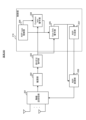
- FIG. 9 is a block diagram showing the main configuration of AP 100 according to this embodiment.
- the AP 100 generates a trigger frame that instructs the terminal 200 to perform NDP transmission for a usage determined from among multiple usages, and transmits the trigger frame to the terminal 200.
- the AP 100 includes a scheduling section 101, an NDP type control section 102, a Common Info generation section 103, a User Info generation section 104, a trigger frame generation section 105, an error correction encoding section 106, a modulation section 107, and a wireless It includes a transmitting/receiving section 108, a demodulating section 109, and an NDP receiving section 110.
- the scheduling section 101 may be included in the control section 111.
- the control unit 111 performs media access control (MAC) access control.
- MAC media access control
- the scheduling section 101 determines the NDP type corresponding to the purpose at the timing of instructing NDP transmission, and outputs it to the NDP type control section 102. Furthermore, the scheduling section 101 determines a terminal ID (Identification) that instructs NDP transmission and NDP radio resource information of the terminal, and outputs them to the Common Info generation section 103 and the User Info generation section 104.
- the terminal's NDP radio resource information includes information on the band (assigned band) that the terminal uses for NDP transmission, information on the sequence that the terminal uses for NDP transmission, information on the number of LTF symbols that the terminal uses for NDP transmission, etc. good.
- the terminal's NDP radio resource information includes information on the band (assigned band) used by each of the multiple terminals for NDP transmission, sequence information, and LTF. Information regarding the number of symbols, etc. may be included.
- the AP instructs the terminal to transmit NDP at a predetermined period.
- the AP instructs the terminal to perform NDP transmission at a predetermined cycle and/or at a timing at which it is determined that the quality deterioration of the terminal is significant.
- the case where the quality deterioration of the terminal is large is, for example, when the reception error rate at the terminal is more than a threshold value, or when the quality information fed back from the terminal to the AP indicates that the quality is worse than a predetermined level. be.
- the NDP type control unit 102 transmits format information indicating the format of a predetermined Common Info field, User Info field, and Special User Info field corresponding to a predefined NDP type. It is output to the User Info generation unit 104 and the Common Info generation unit 103.
- the format information includes information indicating the size of each subfield constituting the field and the interpretation (meaning) of bit information included in each subfield.
- the User Info generation unit 104 uses the format information indicating the format of the predetermined User Info field and Special User Info field corresponding to the NDP type input from the NDP type control unit 102 to generate the terminal ID input from the scheduling unit 101. and/or converting the NDP radio resource information into predetermined bit information. Then, the User Info generation unit 104 generates a User Info field and a Special User Info field including the converted bit information, and outputs them to the Trigger frame generation unit 105.
- the Common Info generation unit 103 uses format information indicating the format of a predetermined Common Info field corresponding to the NDP type input from the NDP type control unit 102 to predetermine the NDP radio resource information input from the scheduling unit 101. Convert to bit information.
- the Common Info generation unit 104 then generates a Common Info field including the converted bit information, and outputs it to the Trigger frame generation unit 105.
- the Trigger frame generation unit 105 generates a User Info List consisting of the Common Info field output from the Common Info generation unit 103, the Special User Info field output from the User Info generation unit 104, and the User Info fields of multiple terminals. Generate a Trigger frame containing. In addition to the Common Info field, Special User Info field, and User Info List, a MAC header, Padding, and FCS (frame check sequence) may be added to the generated Trigger frame. The generated Trigger frame is output to error correction encoding section 106.
- the error correction encoding section 106 inputs, for example, a transmission data signal including a trigger frame, performs error correction encoding on the input signal, and outputs the encoded signal to the modulation section 107.
- the modulating section 107 performs modulation processing on the signal input from the error correction encoding section 106, and outputs the modulated data signal to the wireless transmitting/receiving section 108.
- the AP 100 may perform transmission signal processing related to OFDM.
- the AP 100 e.g., modulation unit 107 maps the modulated signal to a predetermined frequency resource, performs inverse fast Fourier transform (IFFT) processing to convert it into a time waveform, and converts the modulated signal into a time waveform. :Cyclic Prefix) may be added to form an OFDM signal.
- IFFT inverse fast Fourier transform
- :Cyclic Prefix may be added to form an OFDM signal.
- the wireless transmitting/receiving section 108 performs predetermined wireless transmission processing such as D/A (digital-to-analog) conversion and up-conversion to a carrier frequency on the modulated signal output from the modulation section 107, and after the wireless transmission processing, is transmitted to the terminal 200 via the antenna.
- the wireless transmitter/receiver 108 also receives a signal transmitted from the terminal 200 via an antenna, and performs predetermined processing such as down-conversion to baseband and A/D (analog-to-digital) conversion on the received signal. It performs radio reception processing and outputs the signal after the radio reception processing to demodulation section 109 .
- the demodulation section 109 performs demodulation processing on the input signal, for example, and outputs the obtained NDP reception signal to the NDP reception section 110.
- the AP 100 may perform received signal processing related to OFDM.
- the AP eg, demodulation unit
- FFT Fast Fourier Transform
- NDP receiving section 110 performs reception processing corresponding to the NDP type input from NDP type control section 102 on the NDP signal input from demodulation section 109 , and outputs the result of the reception processing to scheduling section 101 . .
- the NDP receiving unit 110 determines the presence or absence of transmission resources (or transmission data) for each terminal based on the NDP signal. For example, the NDP receiving unit 110 determines whether the reception level of the NDP signal is equal to or higher than a predetermined level, and determines whether transmission resources are available for each terminal based on the determination result. NDP receiving section 110 outputs the determination result to scheduling section 101.
- the output determination result may be referred to as Resource request information.
- the NDP receiving unit 110 determines information (for example, a precoding matrix) to be used for MIMO transmission processing based on the NDP signal. For example, the NDP receiving unit 110 determines the frequency response of the propagation path channel from the NDP signal, performs processing such as singular value decomposition on the frequency response, and performs precoding to be applied to the uplink data signal or the downlink data signal. Calculate the matrix. NDP receiving section 110 outputs the calculated precoding matrix to scheduling section 101.
- information for example, a precoding matrix
- the scheduling unit 101 After acquiring the information from the NDP receiving unit 110, the scheduling unit 101 uses the acquired information (for example, the processing result for the NDP received signal (Resource request information, precoding matrix, etc.) to transmit data to the corresponding terminal. Perform data transmission.
- the acquired information for example, the processing result for the NDP received signal (Resource request information, precoding matrix, etc.) to transmit data to the corresponding terminal. Perform data transmission.
- FIG. 10 is a block diagram showing a configuration example of terminal 200 according to this embodiment.
- the terminal 200 includes a radio transmitting/receiving section 201, a demodulating section 202, an error correction decoding section 203, a Common Info decoding section 204, a User info decoding section 205, an NDP type control section 206, an NDP generation section 207, and an NDP generation section 207.
- a modulation section 208 is included.
- the Common Info decoding section 204, the User info decoding section 205, the NDP type control section 206, and the NDP generation section 207 may be included in the control section 210.
- the control unit 210 performs MAC access control.
- the wireless transmitter/receiver 201 receives a received signal with an antenna, performs wireless reception processing such as down-conversion and A/D conversion on the received signal, and outputs the obtained received signal to the demodulator 202.
- the demodulator 202 performs demodulation processing on the received data input from the wireless transmitter/receiver 201 and outputs the demodulated signal to the error correction decoder 203.
- the terminal 200 may perform received signal processing related to OFDM.
- the terminal 200 for example, the demodulating section 202 may perform CP removal processing and FFT processing.
- the error correction decoding section 203 decodes the demodulated signal input from the demodulation section 202 and outputs the decoded signal as a received data signal. Furthermore, error correction decoding section 203 outputs the Trigger frame of the received data signal to Common Info decoding section 204 and User info decoding section 205 .
- the NDP type control unit 206 holds format information indicating the format of a predetermined Common Info field, User Info field, and Special User Info field corresponding to the NDP type.
- the format information held may be the same as the format information held in the NDP type control unit 102 of the AP 100, for example.
- the NDP type control unit 206 outputs format information to the Common Info decoding unit 204 and the User info decoding unit 205.
- the Common Info decoding unit 204 extracts the Common Info field from the Trigger frame output from the error correction decoding unit 203.
- the Common Infor decoding unit 204 decodes the terminal common information using the format information of the Common Info field corresponding to the NDP type output from the NDP type control unit 206, and outputs the terminal common information to the User Info decoding unit 205. .
- the User Info decoding unit 205 extracts the User Info List from the Trigger frame output from the error correction decoding unit 203.
- the extracted User Info List includes one or more User Info fields and a Special User Info field.
- the User Info decoding unit 205 uses the terminal common information output from the Common Info decoding unit 204 and the format information of the User Info field and Special User Info field corresponding to the NDP type output from the NDP type control unit 206. Then, the terminal individual information is decoded, and the terminal individual information is output to NDP generation section 207 and NDP modulation section 208.
- the terminal individual information may include NDP radio resource information.
- the terminal individual information may include NDP radio resource information for each of a plurality of terminals.
- the NDP generation unit 207 generates an NDP signal based on the NDP radio resource information input from the User info decoding unit 205. For example, the NDP generation unit 207 generates an NDP signal using a predetermined sequence indicated by the NDP radio resource information, the number of LTF symbols, and P matrix, which is an orthogonal sequence. NDP generation section 207 outputs the generated NDP signal to NDP modulation section 208.
- the NDP modulation section 208 performs transmission signal processing on the NDP signal input from the NDP generation section 207 based on the NDP radio resource information input from the User Info decoding section 205. For example, the NDP modulation section 208 modulates the NDP signal using a predetermined modulation method and assigns it to a predetermined band (for example, Tone). NDP modulation 208 outputs a modulated signal assigned to a predetermined band (for example, Tone) to wireless transmitter/receiver 209 .
- the modulated signal is an OFDM signal
- terminal 200 may perform transmission signal processing related to OFDM.
- terminal 200 (for example, NDP modulation section 208) may form an OFDM signal by performing IFFT processing after mapping a modulated signal to a frequency resource and adding a CP.
- the wireless transmission/reception unit 201 performs wireless transmission processing such as up-conversion and D/A conversion on the input signal from the NDP modulation unit 208, and transmits the signal after the wireless transmission processing from the antenna.
- the AP 100 uses the Trigger frame to instruct the terminal 200 to perform NDP transmission corresponding to the NDP type determined from among the multiple types.
- the NDP type control unit 102 of the AP 100 holds format information of the predetermined Common Info field, User Info field, and Special User Info field corresponding to the NDP type.
- NDP Network-to-Network Protocol
- MIMO uplink/downlink transmission beamforming
- channel quality estimation may be described as Sounding.
- the frequency band targeted for channel quality estimation may be described as a sounding band.
- NDP used for sounding is referred to as NDP for sounding
- transmitting the NDP for sounding may be referred to as NDP transmission for sounding.
- instructing to transmit the NDP for Sounding corresponds to instructing that the NDP to be transmitted is the NDP for Soundin.
- Sounding NDP transmission instruction may be replaced with "Sounding NDP instruction”.
- NDP transmission for sounding a method may be applied in which the NDP signal of the terminal is allocated in units of RU (clumps of multiple tones) to a predetermined sounding band.
- RU corresponds to a block of multiple tones.
- the method of allocating NDP signals in units of RUs (units of blocks of multiple tones) is sometimes described as localized allocation. Note that allocation in Tone units may correspond to allocation in the smallest allocation unit, and allocation in RU units may correspond to allocation in units of a plurality of minimum allocation units.
- NDP transmission for Sounding is instructed, for example, in the Trigger Type subfield of the Common Info field shown in FIG.
- Sounding NDP is added to the types set in the Trigger Type subfield. Then, by setting information indicating that it is a Sounding NDP in the Trigger Type of the Common Info field, a sounding NDP transmission is instructed.
- FIG. 11 is a diagram showing an example of Trigger Type.
- FIG. 11 shows the correspondence between the value set in the Trigger Type subfield (“Trigger Type subfield value”) and the type indicated by that value (“Trigger frame variant”) in a table format.
- NDP transmission for Sounding (“Sounding NDP" in FIG. 11) is added to the types set in Trigger Type. That is, in FIG. 11, two NDP types are defined: NDP Feedback Report Poll (NFRP) and Sounding NDP transmission.
- NFRP NDP Feedback Report Poll
- NDP transmission for Sounding is associated with the value set in the Trigger Type subfield being 8.
- the value of the Trigger Type subfield is set to 8
- multiple terminals are instructed to perform NDP transmission for Sounding.
- the case where the value of the Trigger Type subfield is set to 8 corresponds to the case where the Trigger Type is NDP transmission for Sounding.
- NDP transmission for Sounding (“Sounding NDP" in Figure 11) is added to the type set in Trigger Type, and a Trigger frame containing the Trigger Type subfield containing information instructing NDP transmission for Sounding is added.
- the AP can appropriately instruct the terminal that the type of NDP is NDP transmission for sounding.
- the type of NDP included in the types set in Trigger Type is "NDP Feedback Report Poll (NFRP)", but in the example shown in Figure 11, There are two types of NDP included in the types set in Trigger Type.
- the AP can select the NDP type to request the terminal to transmit from among the two NDP types, and can instruct the terminal to perform appropriate NDP transmission.
- FIG. 11 shows an example in which NDP transmission for Sounding is instructed in the Trigger Type subfield of the Common Info field, the present disclosure is not limited to this.
- NDP transmission for Sounding may be instructed in a combination of a Common Info field and a field different from the Common Info field (eg, User Info field and/or Special User Info field).
- a Common Info field e.g, User Info field and/or Special User Info field.
- NDP transmission for Sounding is instructed in the Trigger Type of the Common Info field and some subfields of the Special User Info field.
- the Trigger Type of the Common Info field is Basic (the value of the Trigger Type subfield is set to 0)
- some subfields of the Special User Info field are read as NDP type information.
- the type of NDP is specified in some subfields of the Special User Info field.
- subfield A being read as information B may correspond to subfield A being read as subfield B that sets information B.
- subfield A being replaced may correspond to changing the content (or interpretation) of subfield A, or may correspond to subfield A being replaced by subfield B.
- subfield A is replaced with information B when a certain condition X is satisfied means that subfield A is not replaced with information B when a certain condition This may correspond to setting information A that is different from .
- NDP type subfield indicating NDP type information.
- FIG. 12 is a diagram illustrating an example of a method for indicating NDP type information.
- Figure 12 shows the value set in the Trigger Dependent User Info subfield of the Special User Info field ("NDP type subfield value") and the NDP type indicated by that value ("NDP type") when Trigger Type is Basic. ) is shown in a table format.
- Sounding with Localized allocation is defined as the NDP type information. “Sounding with Localized allocation” indicates NDP transmission of Localized allocation for sounding purposes.
- the Trigger Type is Basic
- the value of the Trigger Dependent User Info subfield of the Special User Info field is set based on Figure 12 to specify one of the NDP types defined in Figure 12. be done.
- the Trigger Dependent User Info subfield of the Special User Info field is a Reserved area and is an unused subfield. Therefore, in EHT, no problem occurs even if the Trigger Dependent User Info subfield is replaced with NDP type information.
- the AP transmits a Trigger frame in which NDP type information is set in the Trigger Dependent User Info subfield of the Special User Info field based on the example in Figure 12, and the terminal transmits the Trigger Dependent User Info subfield included in the received Trigger frame.
- the AP can appropriately indicate the NDP type to the terminal. Thereby, it is possible to instruct multiple terminals to transmit NDP of a type selected from multiple types.
- NDP Trigger Dependent User Info subfield of the Special User Info field
- the AP selects the NDP type to request the terminal to transmit, and therefore instruct the terminal to perform appropriate NDP transmission.
- NDP types other than "Sounding with Localized allocation" shown in FIG. 12 will be explained later as appropriate.
- Trigger Type of the Common Info field is Basic (the value of the Trigger Type subfield is 0)
- some subfields of the Special User Info field are read as NDP type information.
- the present disclosure is not limited thereto.
- NDP type For example, for NDP transmission for Sounding, when the Trigger Type of the Common Info field is NFRP (when the value of the Trigger Type subfield is set to 7), some subfields of the Special User Info field are read as NDP type information. It's okay to be hit.
- FIG. 13 is a diagram illustrating an example of a method for indicating NDP type information.
- Figure 13 shows the value set in the Reserved subfield of the Special User Info field (“NDP type subfield value”) and the NDP type (“NDP type”) indicated by that value when the Trigger Type is NFRP. The correspondence is shown in table format.
- FIG. 13 the same NDP type information as in FIG. 12 is defined. However, FIG. 13 differs from FIG. 12 in the value set in the Trigger Dependent User Info subfield corresponding to the NDP type. Further, FIG. 13 differs from FIG. 12 in that NFRP (Resource request) is defined.
- NFRP Resource request
- the Trigger Type When the Trigger Type is NFRP, the Reserved subfield of the Special User Info field is replaced with NDP type information (for example, "NDP Type subfield"). For example, when the Trigger Type is NFRP, the value of the NDP Type subfield is set to 0, thereby instructing conventional NDP transmission for NFRP. On the other hand, when the Trigger Type is NFRP, the value of the NDP Type subfield is set to 1, thereby instructing NDP transmission of Localized allocation for Sounding use.
- NDP Type subfield for example, "NDP Type subfield"
- Trigger Type is NFRP
- Trigger Dependent User Info subfield of the Special User Info field does not exist in EHT.
- a Trigger frame with NDP type information set based on the example in FIG. 13 is sent to the Reserved subfield of the Special User Info field, and the terminal acquires the NDP type information from the Reserved subfield included in the received Trigger frame.
- the AP can appropriately indicate the NDP type to the terminal. With this, it is possible to instruct multiple terminals to perform NDP transmission for a usage selected from multiple usages.
- NDP Trigger Dependent User Info subfield of the Special User Info field
- the AP selects the NDP type to request the terminal to transmit, and therefore instruct the terminal to perform appropriate NDP transmission.
- NDP types other than "Sounding with Localized allocation" shown in FIG. 13 will be explained later as appropriate.
- the terminal common information for NDP transmission for Sounding (for example, the number of EHT-LTF symbols) is indicated by, for example, the Number Of HE/EHT-LTF symbols subfield of the Common Info field. Below, an example will be shown in which the terminal common information is the number of EHT-LTF symbols.
- NDP transmission for Sounding is instructed, the information indicated by "Number Of HE/EHT-LTF symbols subfield" will be read as if another NDP type (for example, NDP for Resource request by NRFP Trigger frame) is instructed.
- NDP type for example, NDP for Resource request by NRFP Trigger frame
- the Number Of HE/EHT-LTF symbols subfield when NDP transmission for Sounding is instructed has a different interpretation than when other NDP types (for example, NDP for Resource request by NRFP Trigger frame) are instructed. It will be done.
- FIG. 14 is a diagram showing an example of how to read the Number Of HE/EHT-LTF symbols subfield.
- Figure 14 shows the correspondence between the value of the Number Of HE/EHT-LTF symbols subfield and the number of symbols when NDP transmission for Sounding is instructed (in the case of "Sounding NDP"), and the correspondence relationship between NDP transmission other than NDP transmission for Sounding.
- the type is specified (“other than Sounding NDP”)
- the correspondence between the value of the Number Of HE/EHT-LTF symbols subfield and the number of symbols is shown in a table format.
- the upper limit of the setting value of the number of EHT-LTF symbols is increased.
- the upper limit of the setting value of the number of EHT-LTF symbols is 8 symbols, whereas NDP transmission for sounding is instructed.
- the upper limit of the setting value of the number of EHT-LTF symbols is greater than 8 symbols (16 symbols in FIG. 14).
- the upper limit of the setting value for the number of EHT-LTF symbols is set to the first value, and the AP will Set the number of EHT-LTF symbols.
- the upper limit of the setting value of the number of EHT-LTF symbols is set to a second value larger than the first value, and the AP , set the number of EHT-LTF symbols.
- the number of EHT-LTF symbols is an example of the size of a signal transmitted by a terminal.
- FIG. 15 is a diagram showing an example of NDP transmission for Sounding.
- FIG. 15 shows the Trigger frame sent from the AP to the terminals 1 and 2, and the NDP transmitted by the terminals 1 and 2 that received the Trigger frame.
- the horizontal axes of the AP, terminal 1, and terminal 2 in FIG. 15 indicate time axes.
- the number of streams (number of terminals) in which NDPs of multiple terminals are orthogonally multiplexed within the Sounding band can be increased. Therefore, the overhead of Sounding NDP transmission from multiple terminals can be reduced.
- spatial multiplexing of EHT-LTF symbols is realized, for example, by multiplying each row of P matrix (corresponding to a Spatial Stream (SS) number), which is an orthogonal sequence, by multiple EHT-LTF symbols.
- P matrix corresponding to a Spatial Stream (SS) number
- SS Spatial Stream
- terminal 1 transmits orthogonally multiplexed EHT-LTF symbols from 8 antennas (8 streams) of terminal 1 using SS numbers 1 to 8.
- Terminal 2 transmits orthogonally multiplexed EHT-LTF symbols from 8 antennas (8 streams) of terminal 2 using SS numbers 9 to 16.
- the NDPs (EHT-LTF symbols) of terminal 1 and terminal 2 are spatially multiplexed using different SS numbers, thereby transmitting the NDPs in RU1 and RU2. Since orthogonal multiplexing can be performed by spatially multiplexing using different SS numbers, wideband sounding can be performed with little overhead.
- the terminal common information for NDP transmission for Sounding (for example, the number of EHT-LTF symbols) is indicated by the Number Of HE/EHT-LTF symbols subfield of the Common Info field. Disclosure is not limited to this.
- Terminal common information for NDP transmission for Sounding may be indicated by some subfields of the Special User Info field. For example, when NDP transmission for Sounding is instructed, some subfields of the Special User Info field may be replaced. For example, the Reserved subfield of the Special User Info field may be used for replacement.
- Terminal individual information for NDP transmission for Sounding (for example, SS number to be multiplied by the number of EHT-LTF symbols) may be indicated by some subfields of the User Info field. For example, when NDP transmission for Sounding is instructed, some subfields of the User Info field may be replaced.
- FIG. 16 is a diagram illustrating an example of replacing the Reserved subfield of the User Info field.
- FIG. 16 shows subfields used to read terminal individual information in the User Info field shown in FIG. 2.
- the AP sets extended information of the SS number to be multiplied by the EHT-LTF symbol of NDP in the Reserved subfield of the User Info field, as shown in FIG.
- the terminal reads the Reserved subfield of the User Info field as extended information of the SS number to be multiplied by the EHT-LTF symbol of NDP.
- the 2 bits of “Number Of Spatial Streams subfield” limit the SS number that can be notified when the upper limit of the spatial multiplexing number of Sounding NDP is increased. Therefore, 1 bit of the Reserved subfield is extended and a total of 3 bits are used to notify the SS number.
- information (SS number) is set in the subfield of the User Info field depending on the NDP type information (for example, depending on whether the NDP type of NDP transmission for Sounding is specified). Appropriate information can be instructed to the terminal according to the NDP type. As a result, even if the upper limit of the number of spatial multiplexes for NDP for Sounding is increased, the number of spatial multiplexes can be specified without any restriction, so that NDP transmission for Sounding from the terminal can be realized with less overhead.
- each terminal is instructed to transmit NDP using tone allocation in which many terminals are sparsely arranged in some channels.
- each terminal is instructed to transmit NDP by relatively densely allocated tones in order to obtain high measurement accuracy in the broadband scheduled by the AP.
- the overhead of NDP transmission from multiple terminals can be reduced by increasing the upper limit of the number of EHT-LTF (or EHTplus-LTF) symbols and increasing the number of spatial multiplexing.
- an allocation method may be applied in which the NDP signal of the terminal is allocated to a predetermined Sounding band at predetermined tone intervals and in units of a predetermined number of tones. This allocation method is called distributed allocation.
- NDP signals can be transmitted over a wide band with the same transmission power density as compared to NDP transmission for sounding using localized allocation described above.
- FIG. 17 is a diagram showing an example of Localized allocation and Distributed allocation.
- the horizontal axis represents frequency
- the vertical axis represents power spectral density (PSD).
- FIG. 17 shows the power spectrum density for each tone.
- PSD power spectral density
- the AP can improve the accuracy of sounding measurement by changing the tone allocation method for sounding NDP transmission in consideration of the ability and/or communication performance of the terminal that instructs NDP transmission.
- NDP transmissions for Sounding multiple types of NDP transmissions with different tone assignments may be defined.
- "Sounding with Distributed allocation” indicating NDP transmission for Sounding with Distributed allocation may be added to the NDP type. Then, similarly to the method of instructing the NDP type in the first example, NDP transmission for Sounding with Distributed allocation may be instructed.
- Terminal common information for example, Tone interval
- Terminal common information for example, Tone interval
- some subfields of the Common Info field may be replaced.
- the Number Of HE/EHT-LTF symbols subfield is replaced with a subfield (“Tone interval subfield”) indicating information regarding tone intervals when NDP transmission for Sounding with Distributed allocation is instructed.
- FIG. 18 is a diagram illustrating an example of notification of tone intervals for distributed allocation.
- FIG. 18 shows the correspondence between the values of the Tone interval subfield and the tone intervals indicated by the values in a table format.
- the value of the Tone interval subfield is set based on the example shown in FIG. 18.
- the AP determines the Tone interval based on Figure 18 and sets information indicating the Ton interval in the Number Of HE/EHT-LTF symbols subfield. do.
- the terminal acquires information regarding the tone interval by replacing the Number Of HE/EHT-LTF symbols subfield with the Tone interval subfield.
- NDP type information for example, depending on whether the NDP type of Sounding NDP transmission for Distributed allocation is specified
- information (Tone interval) is provided in the Number Of HE/EHT-LTF symbols subfield.
- Terminal individual information for example, LTF symbol assigned tone number
- Terminal individual information for example, LTF symbol assigned tone number
- some subfields of the User Info field may be replaced.
- FIG. 19 is a diagram showing an example of reading replacement in the User Info field.
- FIG. 19 shows subfields used to read terminal individual information in the User Infor field shown in FIG. 2.
- the AP assigns the start and number of Tone numbers to allocate EHT-LTF symbols to the SS Allocation subfield and Reserved subfield of the User Info field, as shown in Figure 19. Set the information.
- the terminal reads the SS Allocation subfield and Reserved subfield of the User Info field as information on the start of the tone number and the number of tones to which the EHT-LTF symbol is allocated.
- NDP type information for example, depending on whether NDP transmission for Sounding of Distributed allocation is instructed
- information start of Tone number to which the EHT-LTF symbol is assigned
- Tone number information By setting the NDP information (and Tone number information), it is possible to instruct the terminal to provide appropriate information according to the NDP type.
- the tone number can be set from 1 to 8.
- orthogonal multiplexing can be performed between terminals (streams).
- measurement accuracy can be improved by increasing the number of tones assigned to each antenna and allocating EHT-LTF symbols more closely.
- NDP transmission for Sounding NDP transmission for Sounding with Localized allocation and NDP transmission for Sounding with Distributed allocation were cited, but the present disclosure is not limited to these. Below, variations of NDP transmission for Sounding will be explained.
- repetition transmission may be applied in which a plurality of EHT-LTF (or EHTplus-LTF) symbols multiplied by an orthogonal sequence based on P matrix are repeatedly transmitted a predetermined number of times. That is, the AP may instruct the terminal to send a repetition.
- EHT-LTF or EHTplus-LTF
- the AP causes the terminal to repeatedly transmit EHT-LTF symbols with Localized allocation.
- the band in which EHT-LTF symbols are transmitted in Localized allocation may be the same band in each repetition.
- the AP can improve the accuracy of quality measurement by combining EHT-LTF symbols repeatedly transmitted by terminals.
- the AP causes the terminal to repeatedly transmit EHT-LTF symbols with distributed allocation.
- the band in which EHT-LTF symbols are transmitted in distributed allocation may be the same band in each repetition.
- the terminal transmits a signal with a different assigned tone in each repetition of Repetition transmission. By averaging the estimation results of the received signals, the AP can randomize the effects of interference and improve the accuracy of quality measurements.
- the AP causes the terminal to repeatedly transmit EHT-LTF symbols in the same band using Localized allocation or Distributed allocation.
- the band in which EHT-LTF symbols are transmitted in Localized allocation or Distributed allocation may be the same band in each repetition.
- the AP can select the optimal reception beam by changing the reception analog beam for each repetition transmission of a certain terminal and measuring the quality of the signal received by each beam. Communication performance can be improved by applying the selected reception beam to signal reception from the corresponding terminal.
- an application for updating the optimal reception beam (reception beamforming control) at a predetermined period may be added as an NDP type. For example, if receive beamforming control is instructed as an example of the NDP type, some subfields of the Trigger frame may be replaced with information indicating the number of repetition transmissions of the EHT-LTF symbol.
- the band in which EHT-LTF symbols are transmitted in Localized allocation does not have to be the same band in each repetition.
- the AP may instruct the terminal to transmit in a different band for each repetition.
- the AP may instruct frequency hopping in each repetition. By frequency hopping the EHT-LTF symbol for each repetition transmission, the AP can instruct NDP transmission over a wide band with little overhead (eg, fewer trigger frames).
- UL beamforming management which indicates NDP transmission for sounding to control uplink beamforming, may be added as the NDP type. Then, similar to the method of instructing the NDP type in the first example, NDP transmission by repetition transmission may be instructed.
- NDP transmission may be instructed in which the transmission band is changed for each repetition transmission.
- Terminal common information for example, number of repetitions
- NDP transmission for example, UL beamforming management
- some subfields of the Common Info field may be replaced.
- NDP transmission that applies repetition transmission is instructed, the Reserved subfield of the Common Info field is replaced with a subfield (“Number of repetitions subfield”) indicating information regarding the number of repetitions.
- FIG. 20 is a diagram showing an example of notification of the number of repetitions.
- FIG. 20 shows the correspondence between the value of the Number of repetitions subfield and the number of repetitions of the EHT-LTF symbol indicated by the value in a table format.
- the value of the Number of repetitions subfield is set based on the example shown in FIG. 20.
- the AP determines the number of repetitions based on FIG. 20 and sets information indicating the number of repetitions in the Reserved subfield of the Common Info field.
- the terminal acquires information on the number of repetitions of the EHT-LTF symbol by replacing the Reserved subfield of the Common Info field with the Number of repetitions subfield.
- FIG. 21 is a diagram showing an example of repetition transmission.
- the terminal transmits multiple EHT-LTF symbols twice. Note that the plurality of EHT-LTF symbols to be transmitted may be spatially multiplexed by multiplying orthogonal sequences by P matrix.
- information (repetition number) is set in the Reserved subfield of the Common Info field depending on the NDP type information (for example, depending on whether NDP transmission that applies repetition transmission is instructed). , it is possible to instruct the terminal to provide appropriate information according to the NDP type.
- Terminal individual information for NDP transmission that applies repetition transmission (for example, UL beamforming management) (for example, the offset amount of the transmission band position for each repetition transmission (in Tone units or RU units)) can be found in the User Info field. May be directed by some subfields. For example, when NDP transmission that applies repetition transmission is instructed, some subfields of the User Info field may be replaced.
- the subfield that notifies control information regarding data transmission is replaced with information on the offset amount of the position of the transmission band for each repetition transmission.
- the subfield that notifies control information regarding data transmission is, for example, the UL FEC Coding Type subfield and/or the UL HE-MCS subfield of the User Info field.
- Control information regarding data transmission is unnecessary information for NDP transmission without accompanying data. Therefore, no problem will occur even if the subfield that reports control information regarding data transmission is replaced with a subfield that reports information different from the control information regarding data transmission.
- a value in the range of -15 to 15 is notified using the 5 bits that are the sum of the UL FEC Coding Type subfield and UL HE-MCS subfield of the User Info field.
- the unit of the offset amount may be an RU unit in the case of Localized allocation, and may be a Tone unit in the case of Distributed allocation.
- the terminal transmits the first EHT-LTF symbol of repetition transmission to the band (first band) specified in the RU Allocation subfield. Then, when transmitting the EHT-LTF symbol for the second time in repetition transmission, the terminal transmits the EHT-LTF symbol in a band obtained by adding the offset amount to the first band. Similarly, when transmitting EHT-LTF symbols for the third and subsequent repetition transmissions, the terminal transmits the EHT-LTF symbols in a band obtained by adding an offset amount to the band of the previous repetition transmission.
- the terminal By setting the offset amount to 0 by the AP, the terminal performs each repetition transmission in the same band, and the AP combines the EHT-LTF symbols that the terminal repeatedly transmits in the same band. The accuracy of quality measurements can be improved.
- the AP can select the optimal reception beam by changing the reception analog beam for receiving the NDP transmitted from the terminal in each repetition transmission and measuring the quality of each beam.
- FIG. 22 is a diagram showing an example of frequency hopping.
- FIG. 22 shows an example in which the AP transmits a Trigger frame that triggers NDP transmission, and terminal 1 and terminal 2 perform NDP transmission based on the received Trigger frame.
- the horizontal axes of the AP, terminal 1, and terminal 2 in FIG. 22 indicate time axes.
- terminal 1 transmits an NDP signal (for example, EHT-LTF symbol) in RU2 in the first repetition transmission (“Rep.0” in FIG. 22), and in the second repetition transmission (“Rep.0” in FIG. "Rep.1"), the NDP signal is transmitted using RU1.
- the terminal 2 transmits an NDP signal in RU1, and in the second repetition transmission, it transmits an NDP signal in RU2.
- the NDP signals of terminal 1 and terminal 2 are frequency-multiplexed in each repetition transmission.
- the NDP type information for example, depending on whether the NDP type of NDP transmission for Sounding of Distributed allocation is indicated
- information is provided in the UL FEC Coding Type subfield and/or the UL HE-MCS subfield.
- the NDP type information for example, depending on whether the NDP type of NDP transmission for Sounding of Distributed allocation is indicated
- information is provided in the UL FEC Coding Type subfield and/or the UL HE-MCS subfield.
- offset amount information appropriate information according to the NDP type can be instructed to the terminal.
- the AP can perform wideband sounding with one trigger frame. Note that, as shown in FIG. 22, frequency hopping may be performed while frequency multiplexing the NDPs of multiple terminals. This allows broadband sounding with one Trigger frame.
- the above-described NDP transmission applying repetition transmission may be applied to a method of transmitting by switching the transmission antenna for each repetition transmission in a terminal.
- the antenna configuration of such a terminal is defined as the terminal's capability information, and the antenna configuration is shared in advance between the terminal and the AP to which the terminal connects. For example, in the case of FIG. 7, when the terminal connects to the AP, it notifies the AP of information indicating an antenna configuration of 1T4R as the terminal's capability information.
- the AP instructs the terminal to perform "NDP transmission that switches the transmitting antenna for each repetition transmission" based on the terminal's capability information. Based on the instruction, the terminal switches the transmitting antenna for each repetition transmission and transmits the NDP.
- the AP receives the NDP for each repetition transmission from the terminal, measures the reception quality, compares the reception quality, and selects the optimal transmission antenna for the terminal. For example, the transmitting antenna used for repeat transmission with the best reception quality is selected as the optimal antenna.
- the AP indicates the selected transmitting antenna to the terminal. By using the selected transmitting antenna in the transmission process after receiving the instruction, the terminal can improve uplink communication performance. Furthermore, in an environment where reversibility of channel characteristics can be assumed, the channel characteristics (e.g.
- the AP applies preprocessing to the downlink data signal by estimating the frequency response of the channel between the AP and each of the terminal's receive antennas based on the NDP reception quality for each repetition transmission of the terminal.
- a coding matrix may also be calculated.
- Transmission antenna switching may be added as the NDP type, indicating that the transmission antenna is switched for each repetition transmission. Then, similar to the method of instructing the NDP type in the first example, NDP transmission may be instructed to switch the transmitting antenna for each repetition transmission.
- the terminal receives an NDP transmission instruction to switch the transmitting antenna for each repetition transmission, it repeatedly transmits EHT-LTF symbols equal to the number of receiving antennas/number of transmitting antennas based on the capability of the terminal's antenna configuration.
- FIG. 23 is a diagram showing an example of transmission antenna switching.
- FIG. 23 shows an example of NDP transmitted by a terminal when the antenna configuration is 1T4R.
- the terminal when the antenna configuration is 1T4R, the terminal performs repetition transmission four times, switches the transmission antenna in the order of predetermined antenna numbers for each repetition transmission, and transmits the EHT-LTF symbol.
- Capability information of the antenna configuration of the terminal is notified from the terminal to the AP to which the terminal connects. With this notification, the terminal common information for NDP transmission that switches the transmitting antenna for each repetition transmission does not need to be notified to the terminal.
- the capability information of the antenna configuration of the terminal is notified to the AP to which the terminal connects. With this notification, it is not necessary to notify the terminal of individual terminal information for NDP transmission that switches the transmitting antenna for each repetition transmission. For example, instead of being notified from the AP to the terminal, the number of repetitions can be derived by the terminal from the terminal's capability information.
- ⁇ Variation 3 NDP transmission using ZC sequence>
- a method using a CAZAC (Constant Amplitude Zero Auto Correlation) sequence for example, a Zadoff-Chu (ZC) sequence
- ZC Zadoff-Chu
- a certain terminal A cyclically shifts the ZC sequence used for a certain stream A, and then transmits the cyclically shifted ZC sequence (Cyclic-ZC sequence) to the terminal A.
- A can be applied to other streams different from stream A.
- the cyclically shifted ZC sequence (Cyclic-ZC sequence) can be applied to other terminals different from terminal A.
- NDP transmission for sounding using the ZC sequence is the same as the method of instructing the NDP type in the first example (NDP transmission for sounding) described above.
- NDP transmission may be instructed to switch the transmitting antenna for each repetition transmission.
- Terminal common information for using a ZC sequence to generate an EHT-LTF symbol is not limited to NDP type information.
- terminal common information for using a ZC sequence to generate an EHT-LTF symbol (for example, an EHT-LTF symbol generation sequence) may also be applied to a trigger frame for normal data transmission.
- LTF sequence subfield the subfield in which sequence information is set.
- some subfields (for example, Reserved subfield) of the Special User Info field are read as LTF sequence subfields.
- FIG. 24 is a diagram showing an example of notification of an LTF generation sequence.
- FIG. 24 shows the correspondence between the values of the LTF sequence subfield and the sequences used for LTF indicated by the values in a table format.
- sequence information indicating whether the EHT-LTF symbol is generated using an orthogonal sequence of P matrix or a ZC sequence may be notified in the LTF sequence subfield.
- NDP type information for example, depending on whether NDP transmission for sounding using the ZC sequence is instructed
- information is stored in some subfields (for example, Reserved subfield) of the Special User Info field.
- sequence information By setting (for example, sequence information), appropriate information according to the NDP type can be instructed to the terminal.
- EHT-LTF symbols may be generated by combining spatial multiplexing using P matrix and code multiplexing using CS-ZC sequences. By combining, the number of orthogonal multiplexing can be increased and overhead can be reduced.
- Terminal-specific information for example, ZC sequence number, cyclic shift amount
- Terminal-specific information for example, ZC sequence number, cyclic shift amount
- some subfields of the User Info field may be replaced.
- a subfield that notifies control information regarding data transmission is replaced with information on the ZC sequence number and cyclic shift amount.
- the subfield that notifies control information regarding data transmission is, for example, the UL FEC Coding Type subfield and/or the UL HE-MCS subfield of the User Info field.
- a subfield that includes information on a ZC sequence number and a cyclic shift amount is described as a "ZC subfield.”
- the UL FEC Coding Type subfield and/or UL HE-MCS subfield of the User Info field is replaced with the ZC subfield.
- FIG. 25 is a diagram showing an example of notification of the ZC sequence number and cyclic shift amount.
- FIG. 25 shows, in a table format, the correspondence between the value of the ZC subfield and the ZC sequence number and cyclic shift amount indicated by the value. Based on the example shown in FIG. 25, the value of ZC subfield is set. For example, when the terminal is instructed to use the ZC sequence to generate an EHT-LTF symbol, by replacing the UL FEC Coding Type subfield and/or UL HE-MCS subfield in the User Info field with the ZC subfield, Get the ZC sequence number and cyclic shift amount information.
- the cyclic shift amount is defined in the time unit of symbol length/GI length, taking into consideration the delayed wave of the GI length.
- NDP type information for example, depending on whether NDP transmission for Sounding using a ZC sequence is instructed
- information for example, , ZC sequence number, and cyclic shift amount
- EHT-LTF symbols to be generated using orthogonal CS-ZC sequences between terminals, and NDP signals from multiple terminals can be code-multiplexed in the same band, reducing overhead.
- NDP transmission for 11bf (for sensing)> NDP transmission for multiple uses may include NDP transmission for sensing (for example, a signal for detecting a person or object between a transmitting antenna and a receiving antenna), which is being considered in IEEE802.11bf.
- NDP transmission for sensing specified in 11bf or the above-mentioned NDP transmission for sounding for EHT or EHTplus is instructed to one or more terminals in one Trigger frame.
- FIG. 26 is a diagram illustrating an example of notification of NDP type based on Trigger Type. Similar to FIG. 11, etc., FIG. 26 shows the correspondence between the value set in the Trigger Type subfield (“Trigger Type subfield value”) and the type indicated by that value (“Trigger frame variant”) in a table format. shown.
- Trigger Type subfield value the value set in the Trigger Type subfield
- Trigger frame variant the type indicated by that value
- FIG. 26 "11bf sensing" indicating that the NDP transmission is for 11bf sensing is added to FIG. 11.
- 11bf sensing is associated with the value set in the Trigger Type subfield being 9.
- the terminal can be instructed to transmit NDP for 11bf sensing.
- the example is not limited to adding 11bf sensing to the NDP type based on Trigger Type.
- 11bf sensing may be further added as an NDP type to the examples shown in FIGS. 12 and 13. Then, similar to the method of instructing the NDP type in the first example, NDP transmission for sensing use of 11bf may be instructed as the NDP type.
- the AP can appropriately instruct the terminal to the NDP type. It is possible to instruct multiple terminals to transmit NDP of a type selected from multiple types. Additionally, this allows multiple terminals to instruct not only NDP transmission for sounding purposes for EHT but also NDP transmission for 11bf sensing purposes with a single Trigger frame.
- Terminal individual information for NDP transmission for sensing use for 11bf may be specified by some subfields of the User Info field.
- some subfields of the User Info field may be replaced.
- the Reserved subfield of the User Info field may be replaced with information indicating whether the NDP is for 11bf or for EHT.
- the subfield in which information indicating whether the NDP is for 11bf or the NDP for EHT is set is described as NDP version subfield. In other words, the Reserved subfield of the User Info field may be replaced with the NDP version subfield.
- FIG. 27 is a diagram showing an example of NDP version notification.
- FIG. 27 shows that when the NDP version subfield is set to 0, it is an NDP for EHT or EHTplus, and when the NDP version subfield is set to 1, it is an NDP for 11bf.
- the terminal reads NDP for 11bf, EHT or EHTplus by replacing the Reserved subfield of the User Info field with the NDP version subfield based on Figure 27. Get the NDP version information indicating the
- information for example, NDP version information
- NDP type information for example, depending on whether NDP transmission for sensing use for 11bf is instructed.
- appropriate information can be instructed to the terminal according to the NDP type. Additionally, this allows each terminal to instruct either NDP transmission for EHT sounding purposes or NDP transmission for 11bf sensing purposes with a single Trigger frame.
- the size of the PE (Packet Extension) subfield may be adjusted to make the packet lengths the same.
- some subfields of the User Info field may indicate information related to the size of the PE.
- the AP sets NDP type information indicating the NDP type (an example of the type of response signal) in the first field (or subfield), Information corresponding to the NDP type information (for example, the above-mentioned terminal common information and/or terminal individual information) is set in the second field (or subfield). Then, the AP transmits a trigger frame (an example of a control signal) including the first field and the second field to the terminal. The terminal determines the NDP type based on the first field of the Trigger frame, and acquires information from the second field according to the determined NDP type. With this configuration, the type of response signal can be appropriately instructed to the terminal. Furthermore, it is possible to notify the terminal of appropriate information according to the type of response signal.
- EHT-LTF symbol which is the LTF symbol of the EHT version described in this embodiment
- EHTplus-LTF symbol for the EHTplus version.
- the trigger frame shown in this embodiment is also applied to a trigger signal that instructs joint NDP transmission, which simultaneously transmits NDP signals from multiple APs in the same band, in cooperative AP communication where multiple APs cooperate to communicate. can.
- FIG. 28 is a diagram showing an example of Joint NDP transmission.
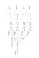
- FIG. 28 shows a Sharing AP that instructs cooperative communication, a Shared AP that performs cooperative communication based on instructions from the Sharing AP, and a terminal (STA).
- the horizontal axes of Sharing AP, Shared AP1, Shared AP1, and STA1 in FIG. 28 indicate the time axis.
- the Sharing AP transmits a Trigger frame instructing multiple Shared APs to transmit NDP.
- Sharing AP and Shared AP transmit NDP using the specified transmission method according to the instructions of the Trigger frame.
- a similar Trigger frame can be applied to a signal that triggers Joint NDP transmission, and the same effect can be obtained.
- some fields of the NDP Announcement frame in which the AP instructs the terminal to provide quality feedback information may be used in the Trigger frame instructing NDP transmission shown in this embodiment.
- the Feedback Type And Ng field which specifies the band for which the terminal sends quality feedback, can be used as the terminal individual information or terminal common information in this embodiment to specify the band for the terminal to perform NDP transmission. It's okay.
- the NDP transmission trigger frame for receiving beamforming control shown in variation 1 can also be applied to a trigger signal for beam control for Hybrid Beamforming used in the IEEE 802.11ay standard, and can be used in the same way.
- This embodiment is not limited to EHT and EHTplus, but can be applied to signals for triggering packets that do not include data (NDP), such as IEEE 802.11ay and IEEE 802.11bf, and similar effects can be obtained.
- NDP data
- the AP transmits a Trigger frame to the terminal, and the terminal transmits the NDP to the AP based on the received Trigger frame
- a communication device e.g., a terminal
- a communication device e.g., AP
- the terminal may transmit the NDP based on the received Trigger frame.
- the terminal individual information notified in the User Info field of this embodiment is not limited to information for one terminal.
- the information may be information for a plurality of terminal groups (for example, a group of terminals with AIDs in a predetermined range).
- the notification information of the NDP types shown in this embodiment may be combined.
- Distributed allocation allows wideband NDP transmission by increasing the allocated tone interval.
- broadband sounding is required with localized allocation, broadband NDP transmission is possible by combining frequency hopping.
- frequency multiplexing can be performed by changing the allocated tone number in one EHT-LTF symbol.
- it is effective to combine a ZC sequence to which a cyclic shift is applied to distributed allocation in order to instruct NDP transmission from multiple terminals in one EHT-LTF symbol.
- ZC sequences By combining ZC sequences with cyclic shifts applied to distributed allocation, the number of orthogonal multiplexing can be increased and NDP transmission of multiple terminals can be performed in one EHT-LTF symbol.
- the information to be notified is not limited to the information shown in the above-described embodiments, and for example, other information may be added. Alternatively, at least part of the defined information may be deleted.
- frame, element, field, subfield, etc. are areas (ranges or configurations) included in a signal, and are examples of names for areas (ranges or configurations) in which information is set. It is. These terms may be read interchangeably.
- the names such as frame, element, field, and subfield in each of the embodiments described above are merely examples, and the present disclosure is not limited to the examples described above.
- different names may be given to the configuration examples of the Common Info field, User Info field, and Special User Info field shown in FIGS. 1, 2, and 3, respectively.
- the definitions of frame, element, field, subfield, etc. in each of the embodiments described above are merely examples, and the present disclosure is not limited to the examples described above.
- the correspondence relationship between the value of the Trigger Type subfield and the type of trigger frame illustrated in FIG. 11 may be changed to a relationship different from that shown in FIG. 11.
- FIGS. 12, 13, etc. the correspondence between the value of the NDP Type subfield and the NDP type may be changed.
- the configurations of frame, element, field, subfield, etc. in each of the embodiments described above are merely examples, and the present disclosure is not limited to the examples described above.
- at least one subfield may be omitted from the above-described field configuration, or the above-described frame configuration may include a subfield that is not included in the configuration.
- the AP that instructs cooperative communication and the AP that is instructed to perform cooperative communication are explained using the terms “Sharing AP” and “Shared AP,” respectively. Terms may be used.
- the explanation has been made based on the 11be format as a non-limiting example, but the format to which an embodiment of the present disclosure can be applied is not limited to the 11be format.
- An embodiment of the present disclosure may be applied, for example, to IEEE 802.11bd (NGV (Next Generation V2X)), which is the next generation standard of IEEE 802.11p, which is an in-vehicle standard.
- NVG Next Generation V2X
- Each functional block used in the description of the above embodiment is partially or entirely realized as an LSI that is an integrated circuit, and each process explained in the above embodiment is partially or entirely realized as an LSI, which is an integrated circuit. It may be controlled by one LSI or a combination of LSIs.
- the LSI may be composed of individual chips, or may be composed of a single chip that includes some or all of the functional blocks.
- the LSI may include data input and output.
- LSIs are sometimes called ICs, system LSIs, super LSIs, and ultra LSIs depending on the degree of integration.
- the method of circuit integration is not limited to LSI, and may be realized using a dedicated circuit, a general-purpose processor, or a dedicated processor. Furthermore, an FPGA (Field Programmable Gate Array) that can be programmed after the LSI is manufactured or a reconfigurable processor that can reconfigure the connections and settings of circuit cells inside the LSI may be used.
- FPGA Field Programmable Gate Array
- reconfigurable processor that can reconfigure the connections and settings of circuit cells inside the LSI may be used.
- the present disclosure may be implemented as digital or analog processing.
- the present disclosure can be implemented in all types of devices, devices, and systems (collectively referred to as communication devices) that have communication capabilities.
- the communication device may include a wireless transceiver and processing/control circuitry.
- the wireless transceiver may include a receiving section and a transmitting section, or both as functions.
- the wireless transceiver (transmitter, receiver) may include an RF (Radio Frequency) module and one or more antennas.
- RF modules may include amplifiers, RF modulators/demodulators, or the like.
- Non-limiting examples of communication devices include telephones (mobile phones, smart phones, etc.), tablets, personal computers (PCs) (laptops, desktops, notebooks, etc.), cameras (digital still/video cameras, etc.) ), digital players (e.g.
- digital audio/video players wearable devices (e.g. wearable cameras, smartwatches, tracking devices), game consoles, digital book readers, telehealth/telemedicine (e.g. These include care/medicine prescription) devices, communication-enabled vehicles or mobile transportation (cars, airplanes, ships, etc.), and combinations of the various devices described above.
- wearable devices e.g. wearable cameras, smartwatches, tracking devices
- game consoles digital book readers
- digital book readers e.g. These include care/medicine prescription) devices, communication-enabled vehicles or mobile transportation (cars, airplanes, ships, etc.), and combinations of the various devices described above.
- Communication equipment is not limited to portable or movable, but also non-portable or fixed equipment, devices, systems, such as smart home devices (home appliances, lighting equipment, smart meters or It also includes measuring instruments, control panels, etc.), vending machines, and any other "things” that can exist on an Internet of Things (IoT) network.
- IoT Internet of Things
- Communication includes data communication using cellular systems, wireless LAN systems, communication satellite systems, etc., as well as data communication using a combination of these.
- Communication devices also include devices such as controllers and sensors that are connected or coupled to communication devices that perform the communication functions described in this disclosure. Examples include controllers and sensors that generate control and data signals used by communication devices to perform communication functions of a communication device.
- Communication equipment also includes infrastructure equipment, such as base stations, access points, and any other equipment, devices, or systems that communicate with or control the various equipment described above, without limitation. .
- a communication device sets first information indicating a type of response signal in a first field, and sets second information corresponding to the first information in a second field. and a transmitting circuit that transmits the control signal.
- the response signal is a signal that is not accompanied by data.
- the first information indicates the type of the response signal selected from a plurality of types.
- the type of the response signal includes a use for measuring communication quality.
- the first information indicates that the response signal is allocated in a unit that includes a plurality of minimum allocation units in the band in which the communication quality is measured.
- the first information indicates that the response signal is allocated in a minimum allocation unit in the band in which the communication quality is measured.
- the control circuit when setting the first information indicating a use different from the use for measuring the communication quality in the first field, sets an upper limit of the size of the response signal to the first field. 1, a size smaller than or equal to the first value is set as the second information in the second field, and the first field indicates the purpose of measuring the communication quality. 1, the upper limit of the size of the response signal is set to a second value larger than the first value, and a size smaller than or equal to the second value is set as the second information. Set in the second field.
- the control circuit when the control circuit sets the first information indicating a use different from the use for measuring the communication quality in the first field, the control circuit determines the frequency interval for allocating the response signal.
- an upper limit is set to a first value
- an interval less than or equal to the first value is set as the second information in the second field
- a purpose for measuring the communication quality is set in the first field.
- the upper limit of the frequency interval to which the response signals are allocated is set to a second value larger than the first value
- the interval less than or equal to the second value is set to the upper limit of the frequency interval to which the response signals are allocated. 2 is set in the second field.
- control circuit includes a size of the response signal, a frequency interval to which the response signal is assigned, a length of a guard interval attached to the response signal, and a frequency interval applied to the response signal. At least one of the number of repetitions of repeated transmission is set in the second field.
- control circuit includes stream information corresponding to an orthogonal sequence applied to the response signal, information regarding frequency hopping of the response signal, a tone number to which the response signal is assigned, and a tone number to which the response signal is assigned. At least one of the transmitting antennas for transmitting is set in the second field.
- the type of the response signal includes an application for uplink or downlink directivity control, an application for switching transmission antennas, and an application for transmitting the response signal using a sequence.
- first information indicating the type of response signal is set in a first field
- second information corresponding to the first information is set in a second field. and transmitting the control signal.
- An embodiment of the present disclosure is useful for wireless communication systems.
Landscapes
- Engineering & Computer Science (AREA)
- Computer Networks & Wireless Communication (AREA)
- Signal Processing (AREA)
- Mobile Radio Communication Systems (AREA)
Abstract
Selon la présente invention, un dispositif de communication comprend : un circuit de commande qui génère un signal de commande dans lequel des premières informations indiquant le type d'un signal de réponse sont définies dans un premier champ et des secondes informations correspondant aux premières informations sont définies dans un second champ ; et un circuit de transmission qui transmet le signal de commande.
Applications Claiming Priority (2)
| Application Number | Priority Date | Filing Date | Title |
|---|---|---|---|
| JP2022-044112 | 2022-03-18 | ||
| JP2022044112 | 2022-03-18 |
Publications (1)
| Publication Number | Publication Date |
|---|---|
| WO2023176523A1 true WO2023176523A1 (fr) | 2023-09-21 |
Family
ID=88022990
Family Applications (1)
| Application Number | Title | Priority Date | Filing Date |
|---|---|---|---|
| PCT/JP2023/008134 WO2023176523A1 (fr) | 2022-03-18 | 2023-03-03 | Dispositif de communication et procédé de communication |
Country Status (1)
| Country | Link |
|---|---|
| WO (1) | WO2023176523A1 (fr) |
Citations (2)
| Publication number | Priority date | Publication date | Assignee | Title |
|---|---|---|---|---|
| US20180359761A1 (en) * | 2015-04-16 | 2018-12-13 | Lg Electronics Inc. | Channel sounding method in wireless communication system and device for same |
| JP2020043560A (ja) * | 2018-09-07 | 2020-03-19 | マーベル ワールド トレード リミテッド | Wlanのアップリンクマルチユーザサウンディング |
-
2023
- 2023-03-03 WO PCT/JP2023/008134 patent/WO2023176523A1/fr unknown
Patent Citations (2)
| Publication number | Priority date | Publication date | Assignee | Title |
|---|---|---|---|---|
| US20180359761A1 (en) * | 2015-04-16 | 2018-12-13 | Lg Electronics Inc. | Channel sounding method in wireless communication system and device for same |
| JP2020043560A (ja) * | 2018-09-07 | 2020-03-19 | マーベル ワールド トレード リミテッド | Wlanのアップリンクマルチユーザサウンディング |
Similar Documents
| Publication | Publication Date | Title |
|---|---|---|
| CN107113824B (zh) | 在无线局域网中使用半正交多址接入的系统和方法 | |
| US9780926B2 (en) | Burst OFDMA supporting MU-MIMO | |
| CN111769918B (zh) | Dmrs端口的指示方法及装置 | |
| KR20180083434A (ko) | 무선랜 시스템에서 이진 시퀀스를 사용하여 stf 신호를 생성하는 방법 및 장치 | |
| KR20180104285A (ko) | 송신 장치 및 송신 방법 | |
| US20230261846A1 (en) | Apparatus and method for communication based on multi-resource unit in wireless local area network system | |
| US20230370237A1 (en) | Communication apparatus and communication method for multiple access point based null data packet feedback report | |
| WO2020241183A1 (fr) | Station de base, terminal et procédé de communication | |
| Lin et al. | acPad: Enhancing channel utilization for 802.11 ac using packet padding | |
| WO2021049172A1 (fr) | Dispositif de communication et procédé de communication | |
| WO2023176523A1 (fr) | Dispositif de communication et procédé de communication | |
| WO2021020083A1 (fr) | Station de base, procédé de transmission et procédé de réception | |
| WO2022097351A1 (fr) | Dispositif de communication et procédé de communication | |
| JP5430306B2 (ja) | 基地局装置及び基地局装置の通信制御方法 | |
| CN115943682A (zh) | 终端及通信方法 | |
| WO2022153579A1 (fr) | Dispositif de communication et procédé de communication | |
| WO2024004596A1 (fr) | Point d'accès, terminal, et procédé de communication | |
| WO2022239426A1 (fr) | Station de base, terminal et procédé de communication | |
| RU2816991C2 (ru) | Базовая станция, способ передачи и способ приема | |
| US20230327717A1 (en) | Communication device and communication method | |
| WO2023079887A1 (fr) | Point d'accès et procédé de communication | |
| WO2022264571A1 (fr) | Point d'accès, terminal et procédé de communication | |
| WO2023149229A1 (fr) | Dispositif de communication et procédé de communication | |
| WO2021084910A1 (fr) | Dispositif de commande de communication sans fil et procédé de commande de communication sans fil | |
| KR20230024285A (ko) | 멀티 유저 다입력 다출력 전송을 위한 통신 장치 및 통신 방법 |
Legal Events
| Date | Code | Title | Description |
|---|---|---|---|
| 121 | Ep: the epo has been informed by wipo that ep was designated in this application |
Ref document number: 23770480 Country of ref document: EP Kind code of ref document: A1 |