WO2023171805A1 - Decorative sheet and method for producing decorative sheet - Google Patents
Decorative sheet and method for producing decorative sheet Download PDFInfo
- Publication number
- WO2023171805A1 WO2023171805A1 PCT/JP2023/009407 JP2023009407W WO2023171805A1 WO 2023171805 A1 WO2023171805 A1 WO 2023171805A1 JP 2023009407 W JP2023009407 W JP 2023009407W WO 2023171805 A1 WO2023171805 A1 WO 2023171805A1
- Authority
- WO
- WIPO (PCT)
- Prior art keywords
- less
- decorative sheet
- protective layer
- surface protective
- ionizing radiation
- Prior art date
Links
Images


Classifications
-
- B—PERFORMING OPERATIONS; TRANSPORTING
- B32—LAYERED PRODUCTS
- B32B—LAYERED PRODUCTS, i.e. PRODUCTS BUILT-UP OF STRATA OF FLAT OR NON-FLAT, e.g. CELLULAR OR HONEYCOMB, FORM
- B32B27/00—Layered products comprising a layer of synthetic resin
-
- E—FIXED CONSTRUCTIONS
- E04—BUILDING
- E04F—FINISHING WORK ON BUILDINGS, e.g. STAIRS, FLOORS
- E04F15/00—Flooring
- E04F15/02—Flooring or floor layers composed of a number of similar elements
Definitions
- the present invention relates to a decorative sheet used for surface decoration of the interior and exterior of buildings, fittings, furniture, fixtures, flooring, etc., and a method for manufacturing the decorative sheet.
- decorative sheets are applied to the surfaces of wood, wood boards, metal plates, noncombustible boards, paper substrates, resin substrates, etc. using adhesives to add design and durability to the surfaces.
- the design can be selected depending on the requirements and purpose, from patterns such as wood grain or stone grain formed using various printing methods to a plain surface without a pattern.
- the glossiness of the surface is also an important item in terms of design, and can be selected from high gloss like a mirror to low gloss with no reflections, depending on requirements and uses.
- imparting durability is an important function of decorative sheets as well as design. Durability is a comprehensive evaluation of scratch resistance, stain resistance, and whether these can be guaranteed over a long period of time.Requirements vary depending on the environment and situation in which the decorative sheet is used. There is always a demand for decorative sheets with high performance. To impart durability, it is common to form a surface protective layer on the outermost surface of the decorative sheet. Furthermore, in order to adjust the glossiness described above, particularly to achieve low gloss, it is common to add a gloss adjuster (matting additive) to the surface protective layer.
- decorative sheets are generally subjected to processing such as cutting and bending in order to form decorative boards and decorative materials, it is preferable that the decorative sheets have processability that can withstand these processes.
- An example of a decorative sheet in which design (low gloss), scratch resistance, and stain resistance are taken into consideration is the decorative sheet described in Patent Document 1, for example.
- the present invention has low gloss and excellent design, and also has fingerprint resistance, high durability (particularly scratch resistance and stain resistance), and processability (on the base material).
- An object of the present invention is to provide a decorative sheet having a laminating process and a method for manufacturing the same.
- the present inventors optimized the uneven shape of the surface protective layer and conducted repeated experiments to find the necessary structural elements for the material used for the surface protective layer, thereby achieving a gloss level of 15 or less and fingerprint resistance.
- a decorative sheet includes a raw fabric layer and a surface protective layer provided on one surface of the raw fabric layer, and the glossiness of the surface protective layer is is 15 or less, the surface protective layer has a ridge-like protruding portion on its surface, and an uneven shape is formed, and the surface protective layer has a main material that is free from ionizing radiation.
- the ionizing radiation curable resin is a curable resin, and the ionizing radiation curable resin is a tetrafunctional acrylic resin containing a repeating structure as a main component, and the number of repetitions of the repeating structure is 12 or more.
- the vinyl group contained is 20% or less with respect to the carbonyl group contained in the ionizing radiation curable resin, and the RSm/Ra of the uneven shape of the surface protective layer is within the range of 10 to 300.
- the gist is something.
- a decorative sheet that has a gloss level of 15 or less and is compatible with fingerprint resistance, scratch resistance, stain resistance, and processability.
- FIG. 1 is a schematic cross-sectional view illustrating one configuration of a surface protective layer of a decorative sheet according to an embodiment of the present invention.
- 1 is a plan view photograph showing an example of the surface structure of a surface protective layer of a decorative sheet according to an embodiment of the present invention.
- It is a schematic sectional view explaining the cross-sectional shape of the ridged part concerning an embodiment of the present invention.
- FIG. 2 is a schematic cross-sectional view illustrating a measurement method of a curl test.
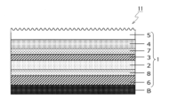
- the decorative sheet 1 of this embodiment has a pattern layer 3, an adhesive layer 7 (thermal adhesive layer, anchor coat layer) on one surface side of the raw fabric layer (base material layer) 2. , dry laminate adhesive layer), transparent resin layer 4 and surface protection layer 5 are laminated in this order.
- a concealing layer 8 and a primer layer 6 are provided on the other surface of the raw fabric layer 2, that is, the back surface side.
- the pattern layer 3, adhesive layer 7, transparent resin layer 4, hiding layer 8, and primer layer 6 may be omitted.
- the decorative sheet 1 of this embodiment constitutes a decorative material 11 by being bonded to a substrate B, as shown in FIG.
- the substrate B is not particularly limited, but may be made of, for example, a wooden board, an inorganic board, a metal plate, a composite board made of a plurality of materials, or the like.
- any material selected from among, for example, paper, synthetic resin, foamed material of synthetic resin, rubber, nonwoven fabric, synthetic paper, metal foil, etc. can be used.
- paper include thin paper, titanium paper, and resin-impregnated paper.
- synthetic resin include polyethylene, polypropylene, polybutylene, polystyrene, polycarbonate, polyester, polyamide, ethylene-vinyl acetate copolymer, polyvinyl alcohol, and acrylic.
- Rubbers include ethylene-propylene copolymer rubber, ethylene-propylene-diene copolymer rubber, styrene-butadiene copolymer rubber, styrene-isoprene-styrene block copolymer rubber, styrene-butadiene-styrene block copolymer rubber, and polyurethane.
- I can give an example.
- the nonwoven fabric organic or inorganic nonwoven fabric can be used.
- the metal of the metal foil include aluminum, iron, gold, and silver.
- the surface of the raw fabric layer 2 is often in an inactive state, so a primer layer 6 is provided between the raw fabric layer 2 and the base material B. It is preferable to provide one.
- the raw fabric layer 2 may be subjected to, for example, corona treatment, plasma treatment, ozone treatment, electron beam treatment, etc. Surface modification treatments such as ultraviolet ray treatment, dichromic acid treatment, etc. may be performed.
- the primer layer 6 the same material as the pattern layer 3, which will be described later, can be used. Since the primer layer 6 is applied to the back side of the decorative sheet 1, considering that the decorative sheet 1 is wound up into a web shape, the primer layer 6 is applied to avoid blocking and improve adhesion with the adhesive.
- An inorganic filler may be added to 6. Examples of the inorganic filler include silica, alumina, magnesia, titanium oxide, and barium sulfate.
- the thickness of the original fabric layer 2 is preferably within the range of 20 ⁇ m or more and 250 ⁇ m or less, considering printing workability, cost, and the like.
- the pattern layer 3 is a pattern printed layer that is printed on the original fabric layer 2 using ink.
- the binder for the ink for example, nitrified cotton, cellulose, vinyl chloride-vinyl acetate copolymer, polyvinyl butyral, polyurethane, acrylic, polyester, and the like can be used alone or appropriately selected from modified products thereof.
- the binder may be aqueous, solvent-based, or emulsion type, and may be a one-part type or a two-part type using a hardening agent.
- a method may be used in which a curable ink is used and the ink is cured by irradiation with ultraviolet rays, electron beams, or the like.
- the most common method is to use urethane-based ink, which is hardened with isocyanate.
- the pattern layer 3 includes, for example, pigments contained in ordinary inks, coloring agents such as dyes, extender pigments, solvents, various additives, and the like.
- highly versatile pigments include pearl pigments such as condensed azo, insoluble azo, quinacridone, isoindoline, anthraquinone, imidazolone, cobalt, phthalocyanine, carbon, titanium oxide, iron oxide, and mica.
- ink In addition to applying ink, it is also possible to create a design on the pattern layer 3 by vapor deposition or sputtering of various metals. In particular, it is preferable that a light stabilizer is added to the ink, thereby suppressing the deterioration of the decorative sheet 1 itself caused by photodeterioration of the ink and extending the life of the decorative sheet 1.
- the adhesive layer 7 is also called a heat-sensitive adhesive layer, an anchor coat layer, or a dry laminate adhesive layer.
- the resin material for the adhesive layer 7 is not particularly limited, but may be appropriately selected from acrylic, polyester, polyurethane, epoxy, and other resin materials. Further, as the resin material for the adhesive layer 7, for example, an ethylene-vinyl acetate copolymer resin adhesive can also be used.
- the coating method can be selected appropriately depending on the viscosity of the adhesive, etc., but generally gravure coating is used, and after coating the upper surface of the pattern layer 3 by gravure coating, the transparent resin layer is coated. It is designed to be laminated with 4. Note that the adhesive layer 7 can be omitted if sufficient adhesive strength between the transparent resin layer 4 and the pattern layer 3 can be obtained.
- olefin resin As the resin material for the transparent resin layer 4, olefin resin is suitably used.
- olefin resins include polypropylene, polyethylene, polybutene, and ⁇ -olefins (e.g., propylene, 1-butene, 1-pentene, 1-hexene, 1-heptene, 1-octene, 1-nonene, 1 -decene, 1-undecene, 1-dodecene, tridecene, 1-tetradecene, 1-pentadecene, 1-hexadecene, 1-heptadecene, 1-octadecene, 1-nonadecene, 1-eicosene, 3-methyl-1-butene, 3 -Methyl-1-pentene, 3-ethyl-1-pentene, 4-methyl-1-pentene, 4-methyl-1-hexene, 4,4-dimethyl-1-pentene
- Copolymer ethylene/vinyl alcohol copolymer, ethylene/methyl methacrylate copolymer, ethylene/ethyl methacrylate copolymer, ethylene/butyl methacrylate copolymer, ethylene/methyl acrylate copolymer, ethylene/ethyl acrylate copolymer
- examples include copolymerization of ethylene or ⁇ -olefin with other monomers, such as ethylene/butyl acrylate copolymer.
- the resin for the transparent resin layer 4.
- various additives such as a heat stabilizer, a light stabilizer, an antiblocking agent, a catalyst scavenger, a coloring agent, a light scattering agent, and a gloss adjusting agent may be added to the transparent resin layer 4 as necessary. You can also.
- heat stabilizers phenol-based, sulfur-based, phosphorus-based, hydrazine-based, etc. are generally added, and as light stabilizers, hindered amine-based, etc. are added in arbitrary combinations.
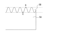
- the surface protective layer 5 has a core portion 5A and a ridge-like portion 5B provided in a ridge-like manner protruding from one surface of the core portion 5A. Thereby, an uneven shape is formed on the surface of the surface protection layer 5.
- the term "ridged” refers to a shape that is elongated and raised in a linear manner in a plan view.
- the ridged portions 5B may be curved or linear in plan view, but are preferably curved from the viewpoint of anti-fingerprint properties of the surface of the decorative sheet 1.
- the ridged portion 5B is, for example, a portion from the lowest part to the tip of the uneven shape provided on the surface of the surface protective layer 5, and the core portion 5A is the ridged portion of the surface protective layer 5. This refers to the part excluding 5B.
- FIG. 2 is a cross-sectional view schematically showing a cross section of the ridged portion 5B of the surface protective layer 5 (a cross section in the thickness direction of the surface protective layer 5), and FIG. This is a planar photograph shown.
- FIG. 3 is a plane photograph obtained using a laser microscope (OLS-4000 manufactured by Olympus).
- the ridged portion 5B has a shape that is elongated and swollen and linearly connected in a plan view.
- the ridged portion 5B is formed by irradiating the surface of the ionizing radiation curable resin with light of a specific wavelength to cause the surface of the ionizing radiation curable resin to contract, as will be described later.
- the shape of the ridged portion 5B is determined by the surface roughness index RSm ( ⁇ m) in the horizontal direction (the plane direction of the surface protective layer 5, and the horizontal direction in FIG. 2) and the vertical direction (the ridged portion 5B).
- the surface roughness index Ra ( ⁇ m) in the depth direction of the surface protective layer 5 (in the vertical direction in FIG. 2) can be expressed as the ratio RSm/Ra, It is 10 or more and 300 or less. More preferably, it is 50 or more and 300 or less.
- RSm/Ra is less than 10
- the shape of the ridged portions 5B is too small, making it difficult to wipe off dirt, resulting in poor stain resistance.
- RSm/Ra is greater than 300, the intervals between the ridges are too wide, resulting in poor gloss.
- RSm/Ra is more preferably 100 or more and 300 or less.
- the spacing between the ridges is appropriately wide, and the affinity for water or cleaning agents (water containing surfactant or alcohol) is improved. Therefore, if the decorative sheet has RSm/Ra within the numerical range, even if the surface of the decorative sheet becomes dirty, the stain can be easily wiped off using water or a detergent.
- RSm/Ra is most preferably 100 or more and 250 or less. If RSm/Ra is within this numerical range, commonly commercially available cleaning sponges will easily penetrate between the ridges, and even if the surface of the decorative sheet is dirty, it will be easier to use commercially available cleaning sponges. It becomes easy to wipe off dirt using the cleaning sponge provided.
- RSm ( ⁇ m) may be 50 or more and 400 or less, preferably 80 or more and 300 or less. If RSm ( ⁇ m) is within this numerical range, the spacing between the ridges is appropriately wide, so the affinity for water or detergent (water containing surfactant or alcohol) is improved. Therefore, if the decorative sheet has RSm ( ⁇ m) within the numerical range, even if the surface of the decorative sheet becomes dirty, the stain can be easily wiped off using water or a detergent.
- Ra ( ⁇ m) may be 0.5 or more and 10 or less, preferably 0.8 or more and 5 or less.
- Ra ( ⁇ m) is within this numerical range, commonly commercially available cleaning sponges will easily penetrate between the ridges, and even if the surface of the decorative sheet is dirty, it will generally be difficult to clean. It becomes easy to wipe off dirt using a commercially available cleaning sponge.
- Ra and RSm are measured values using a line roughness meter (based on JIS B0601).
- the cross-sectional shape of the ridged portion 5B in the thickness direction of the surface protective layer 5 may be a sine wave shape.
- the "sine wave shape” refers to a shape in which a line from the lowest position C to the highest position (apex) D of the ridged portion 5B can be expressed as a sine wave, as shown in FIG.
- acrylate When acrylate is irradiated with light having a wavelength of 200 nm or less as the first irradiation light, acrylate can be self-excited. Therefore, by irradiating the acrylate with light of 200 nm or less, it becomes possible to crosslink the acrylate. Light of 200 nm or less reaches a depth of several tens to hundreds of nm in acrylate. As a result, only the surface is crosslinked, and the underlying portion has fluidity, resulting in a fine uneven shape that is continuous in a wavy manner, such as folding wrinkles.
- the core portion 5A and the ridged portion 5B are formed in an integral and continuous state.
- Light of 200 nm or less is absorbed by oxygen in the atmosphere and is greatly attenuated. Therefore, when processing acrylate, it is necessary to control the reaction atmosphere by introducing nitrogen gas.
- the residual oxygen concentration in the reaction atmosphere is preferably suppressed to 2000 ppm or less. More preferably, the residual oxygen concentration in the reaction atmosphere is 1000 ppm or less.
- the integrated light amount of the first irradiation light is 0.5 mJ/cm 2 or more and 200 mJ/cm 2 or less. More preferably, the integrated light amount is 1 mJ/cm 2 or more and 100 mJ/cm 2 or less. More preferably, the integrated light amount is 3 mJ/cm 2 or more and 50 mJ/cm 2 or less. Most preferably, the integrated light amount is 5 mJ/cm 2 or more and 30 mJ/cm 2 or less.
- the curing shrinkage reaction When the cumulative light amount is less than 0.5 mJ/cm 2 , the curing shrinkage reaction is weak and the uneven shape is not sufficiently formed, so that the gloss does not decrease. When the cumulative light amount is more than 200 mJ/cm 2 , the curing and shrinkage reaction becomes too strong and the surface condition deteriorates.
- Excimer VUV light can be produced from noble gas or noble gas halide compound lamps.
- a gas such as a rare gas or a rare gas halide compound
- This plasma discharge excites the atoms of the discharge gas (rare gas) and instantaneously becomes an excimer state.
- this excimer state When returning from this excimer state to the ground state, it emits light in a wavelength range unique to that excimer.
- the gas used in the excimer lamp may be any conventionally used gas as long as it emits light of 200 nm or less.
- a rare gas such as Xe, Ar, or Kr
- a mixed gas of a rare gas such as ArBr or ArF and a halogen gas
- Excimer lamps have different wavelengths (center wavelengths) depending on the gas, such as approximately 172 nm (Xe), approximately 126 nm (Ar), approximately 146 nm (Kr), approximately 165 nm (ArBr), and approximately 193 nm (ArF).
- a xenon lamp that emits excimer light with a center wavelength of 172 nm as the light source. Furthermore, when considering the cost of equipment maintenance and the availability of materials, it is preferable to use a xenon lamp as the light source.
- the first irradiation light which has a wavelength of 200 nm or less, reaches only a few tens to several hundred nm from the outermost surface of the acrylate, so the ridges formed by the irradiation with light of 200 nm or less
- the inside of the surface protective layer 5 containing 5B has fluidity, and the curing reaction must proceed further.
- the third irradiation light for example, after irradiation with the second irradiation light, a type of ionizing radiation different from the second irradiation light or UV light having a longer wavelength than the second irradiation light is used as the third irradiation light.
- the third irradiation light may be applied when the strength of the surface protective layer 5 is not sufficient only by irradiation with the second irradiation light.
- the cumulative amount of the second irradiation light be 10 mJ/cm 2 or more and 500 mJ/cm 2 or less. More preferably, the integrated light amount is 50 mJ/cm 2 or more and 400 mJ/cm 2 or less. More preferably, the integrated light amount is 100 mJ/cm 2 or more and 300 mJ/cm 2 or less.
- the cumulative light amount is less than 10 mJ/cm 2 , the curing reaction is weak and sufficient strength cannot be imparted to the entire surface protective layer 5, so the scratch resistance tends to decrease. Furthermore, if the cumulative amount of light is more than 200 mJ/cm 2 , the curing reaction becomes too strong and the surface condition tends to deteriorate.
- the cumulative amount of light of the second irradiation light is larger than the cumulative amount of light of the first irradiation light.
- the integrated light amount of the second irradiation light is preferably 1.1 times or more and 50.0 times or less, more preferably 5.0 times or more and 30.0 times or less, than the integrated light amount of the first irradiation light.
- the cumulative amount of light of the second irradiation light is less than 1.1 times the cumulative amount of light of the first irradiation light, the curing reaction is weak and it may not be possible to impart sufficient strength to the entire surface protection layer 5.
- the curing reaction for the entire surface protective layer 5 will become too strong, and the shape of the ridged portion 5B will change. May be deformed.
- FIG. 5 is a diagram schematically showing a temporal change in the amount of irradiation light of the first irradiation light and a time change of the amount of irradiation light of the second irradiation light.
- FIGS. 5(a), (c), (e), (g), and (i) are diagrams schematically showing temporal changes in the amount of irradiation light of the first irradiation light.
- FIGS. 5(b), (d), (f), (h), and (j) are diagrams schematically showing temporal changes in the amount of irradiation light of the second irradiation light.
- the irradiation light amount of the first irradiation light may gradually increase as the irradiation time passes, and then gradually decrease as the irradiation time passes, as shown in FIG. 5(a). Moreover, the irradiation light amount of the first irradiation light may gradually decrease as the irradiation time elapses, as shown in FIG. 5(c). Moreover, the irradiation light amount of the first irradiation light may gradually increase as the irradiation time elapses, as shown in FIG. 5(e).
- the irradiation light amount of the first irradiation light may gradually decrease as the irradiation time passes, and then gradually increase as the irradiation time passes, as shown in FIG. 5(g).
- the irradiation light amount of the first irradiation light may be constant from the start of irradiation to the end of irradiation, as shown in FIG. 5(i).
- the irradiation light amount of the second irradiation light may gradually increase as the irradiation time passes, and then gradually decrease as the irradiation time passes, as shown in FIG. 5(b). Moreover, the irradiation light amount of the second irradiation light may gradually decrease as the irradiation time elapses, as shown in FIG. 5(d). Moreover, the irradiation light amount of the second irradiation light may gradually increase as the irradiation time elapses, as shown in FIG. 5(f).
- the irradiation light amount of the second irradiation light may gradually decrease as the irradiation time passes, and then gradually increase as the irradiation time passes, as shown in FIG. 5(h).
- the irradiation light amount of the second irradiation light may be constant from the start of irradiation to the end of irradiation, as shown in FIG. 5(j).
- the irradiation forms of the first irradiation light shown in FIGS. 5(a), (c), (e), (g), and (i), and the ), (f), (h), and (j) can be used in appropriate combinations with the irradiation forms of the second irradiation light.
- the irradiation form of the first irradiation light shown in FIG. 5(a) and the irradiation form of the second irradiation light shown in FIG. 5(f) may be used in combination.
- the irradiation form of the first irradiation light shown in FIG. 5(c) and the second irradiation form shown in FIG. 5(f) It is more preferable to use it in combination with the light irradiation mode.
- the ridged portions 5B formed by irradiation with light of 200 nm or less have a finer structure than the uneven shapes formed on the surface of the surface protective layer 5 by mechanical processing such as embossing. It has become.
- the layer thickness of the surface protective layer 5 is preferably in the range of 2 ⁇ m or more and 20 ⁇ m or less. More preferably, the layer thickness of the surface protective layer 5 is in the range of 3 ⁇ m or more and 20 ⁇ m or less. More preferably, the layer thickness of the surface protective layer 5 is in the range of 5 ⁇ m or more and 15 ⁇ m or less. Most preferably, the layer thickness of the surface protective layer 5 is in the range of 5 ⁇ m or more and 12 ⁇ m or less.
- the layer thickness of the surface protective layer 5 is less than 2 ⁇ m, shaping by vacuum ultraviolet light does not penetrate deeply, and low gloss cannot be achieved. Moreover, if the layer thickness of the surface protective layer 5 is made thicker than 20 ⁇ m, the workability will be lowered and whitening will occur during bending.
- the layer thickness of the surface protective layer 5 is such that the ratio of the layer thickness of the ridged portion 5B to the layer thickness of the core portion 5A (layer thickness of the ridged portion 5B/layer thickness of the core portion 5A) is 0.01 or more. It is preferable to set it to .0 or less, and more preferably to set it to 0.1 or more and 1.0 or less.
- the pattern layer 3 and the surface protection layer 5 can be formed by various printing methods such as a gravure printing method, an offset printing method, a screen printing method, an electrostatic printing method, and an inkjet printing method.
- the surface protective layer 5 covers the entire surface of the surface side of the raw fabric layer 2, it can also be coated with various coating methods such as roll coating, knife coating, microgravure coating, and die coating. can be formed. These printing methods or coating methods may be selected separately depending on the layer to be formed, or the same method may be selected for batch processing.
- the pattern layer 3 and the surface protection layer 5 may be synchronized from the viewpoint of design.
- the gravure printing method is advantageous in terms of cost since it can be applied at relatively high speeds.
- synchronization means that 50% or more, preferably 70% or more, and most preferably 90% or more of the area on which the surface protective layer 5 is formed overlaps with the pattern part of the pattern layer 3 in plan view. do.
- the coating amount may be adjusted in the above-described printing method and coating method. The coating amount can be calculated from the difference in mass between two types of substrates (original fabric layers) with and without a surface protective layer formed thereon, using various printing methods and coating methods.
- the main material of the surface protective layer 5 is an ionizing radiation curable resin.
- the main material refers to a material containing 60 parts by mass or more, more preferably 70 parts by mass or more, and most preferably 80 parts by mass or more, based on 100 parts by mass of the surface protective layer.
- known resins such as various monomers and commercially available oligomers can be used, such as (meth)acrylic resins, silicone resins, and polyester resins. , urethane resin, amide resin, and epoxy resin can be used.
- the ionizing radiation-curable resin may be either an aqueous resin or a non-aqueous (organic solvent-based) resin.
- the main component of the ionizing radiation-curable resin constituting the surface protective layer 5 is a tetrafunctional acrylate resin containing a repeating structure.
- the tetrafunctional acrylate resin for example, pentaerythritol tetraacrylate can be used.
- the main component refers to 60 parts by mass or more, more preferably 70 parts by mass or more, and most preferably 80 parts by mass or more, based on 100 parts by mass of the constituent resin components.
- trifunctional or less acrylate resins the degree of crosslinking is insufficient and the scratch resistance decreases, which is not preferable.
- the degree of crosslinking becomes too high, which reduces processability, which is not preferable.
- the ionizing radiation curable resin has a suitable viscosity range of 10 to 500 mPa ⁇ s, and an optimum viscosity range of 50 to 300 mPa ⁇ s.
- an organic solvent or a bifunctional acrylate resin with low viscosity can be added.
- organic solvents it is preferable not to use organic solvents.
- Bifunctional acrylate resin is not preferable because scratch resistance decreases if the amount added is large.
- the content of the bifunctional acrylate resin is within the range of 10% by mass or more and 30% by mass or less of the content (mass) of the tetrafunctional acrylate resin. is preferable, and more preferably within the range of 15% by mass or more and 20% by mass or less.
- the viscosity range of the ionizing radiation-curable resin may be 10 to 80 mPa ⁇ s, preferably 10 to 50 mPa ⁇ s. If the viscosity range of the ionizing radiation-curable resin is within this numerical range, the versatility of the coating method will increase. Further, the viscosity range of the ionizing radiation-curable resin may be 200 to 250 mPa ⁇ s, preferably 220 to 250 mPa ⁇ s. If the viscosity range of the ionizing radiation-curable resin is within this numerical range, fine uneven shapes are likely to be formed.
- the above repeating structure is preferably any one of an ethylene oxide (EO) structure, a propylene oxide (PO) structure, and an ⁇ -caprolactone (CL) structure. More preferably, the repeating structure is ethylene oxide or propylene oxide.
- the ethylene oxide structure, propylene oxide structure, and ⁇ -caprolactone structure are preferable because the molecules can freely rotate and have high flexibility, so the molecules are easily folded by light of 200 nm or less and a fine uneven shape is easily formed. Further, the number of times this repeating structure is repeated is 12 or more. More preferably, it is 12 or more and 50 or less, most preferably 20 or more and 50 or less.
- the ionizing radiation-curable resin constituting the surface protective layer 5 will not sufficiently shrink when vacuum ultraviolet light (VUV light) is irradiated, and the surface protective layer 5 will not have low gloss.
- VUV light vacuum ultraviolet light
- the number of repetitions is greater than 50, the crosslinking density decreases and the scratch resistance of the surface protective layer 5 deteriorates.
- the number of repetitions of the above-mentioned repeating structure can be analyzed by using MALDI-TOF-MS.
- Ionizing radiation-curable resins may have a molecular weight distribution.
- the number of repetitions is the number of repetitions corresponding to the molecular weight having the strongest peak in the MALDI-TOF-MS mass spectrum.
- the ratio of the vinyl groups contained in the ionizing radiation curable resin to the carbonyl groups contained in the ionizing radiation curable resin is determined by the Fourier method. It can be analyzed using a type infrared spectrometer. By calculating the peak area around 1400 cm ⁇ 1 derived from vinyl groups and the peak area around 1720 cm ⁇ 1 derived from carbonyl groups, the vinyl group/carbonyl group ratio (content ratio) can be calculated. . The smaller the percentage of vinyl groups, the higher the reaction rate, the higher the crosslinking density, and the higher the scratch resistance. Therefore, the vinyl group/carbonyl group ratio is preferably 20% or less.
- the vinyl group/carbonyl group ratio is more preferably 10% or less, still more preferably 8% or less, and most preferably 5% or less. Further, the ratio of vinyl group/carbonyl group is preferably 0.01% or more. When the vinyl group/carbonyl group ratio is 0.01% or more, excellent scratch resistance can be imparted. Note that the vinyl group does not need to be present in the ionizing radiation curable resin.
- the vinyl group/carbonyl group ratio (content ratio) means "molar ratio".
- the ratio of vinyl groups/carbonyl groups in the ridged portion 5B may be larger than the ratio of vinyl groups/carbonyl groups in the core portion 5A.
- the ratio of the vinyl group/carbonyl group in the ridged part 5B to the vinyl group/carbonyl group in the core part 5A ((vinyl group/carbonyl group in the ridged part 5B)/(vinyl group/carbonyl group in the core part 5A) The group)) may be 1.1 or more and 200 or less, and more preferably 1.1 or more and 100 or less.
- the flexibility of the surface protective layer 5 (especially the ridged portion 5B) can be increased. can.
- the ratio of vinyl groups/carbonyl groups in the ridged portion 5B may be larger than the ratio of vinyl groups/carbonyl groups in the core portion 5A.
- the ratio of the vinyl group/carbonyl group in the ridged part 5B to the vinyl group/carbonyl group in the core part 5A ((vinyl group/carbonyl group in the ridged part 5B)/(vinyl group/carbonyl group in the core part 5A) The group)) may be 0.01 or more and 0.99 or less, and more preferably 0.05 or more and 0.99 or less.
- the ratio of the vinyl group/carbonyl group in the ridged portion 5B to the vinyl group/carbonyl group in the core portion 5A is within the above numerical range, the strength of the surface protective layer 5 (especially the ridged portion 5B) can be increased. .
- the ratio of vinyl groups/carbonyl groups in the ridged portion 5B and the ratio of vinyl groups/carbonyl groups in the core portion 5A may be the same.
- the surface protective layer 5 may contain particles. By adding particles of optimum particle size and optimum content, a uniform surface can be formed.
- the particles for example, organic materials such as PE wax, PP wax, and resin beads, or inorganic materials such as silica, glass, alumina, titania, zirconia, calcium carbonate, and barium sulfate can be used.
- the average particle diameter (D50) of the particles is preferably 10 ⁇ m or less. More preferably, it is 1 ⁇ m or more and 8 ⁇ m or less, still more preferably 2 ⁇ m or more and 6 ⁇ m or less, and most preferably 3 ⁇ m or more and 5 ⁇ m or less. If it is larger than 10 ⁇ m, it is not preferable because the scratch resistance decreases due to particles falling off. If it is less than 1 ⁇ m, it is not preferable because the effect of making the surface uniform is small.
- the amount of particles added is preferably 0.5 parts by mass or more and 10 parts by mass or less based on 100 parts by mass of the ionizing radiation curable resin. More preferably, the amount of particles added is 2 parts by mass or more and 8 parts by mass or less, still more preferably 2 parts by mass or more and 6 parts by mass or less, and most preferably 4 parts by mass or more and 5 parts by mass or less. It is preferable that the surface protective layer 5 contains particles in the above-mentioned amount since it can form a uniform surface condition.
- the "particle size (average particle size)" may be the value (average value) obtained by measuring the particle size distribution of the particles used, or the particle size of multiple particles may be determined from cross-sectional observation of the obtained decorative material.
- the average particle diameter of the particles added to the surface protective layer 5 may be the median diameter (D50) measured with a laser diffraction/scattering particle size distribution measuring device.
- a photoinitiator When the entire surface protective layer 5 is cured by UV light, it is necessary to add a photoinitiator to the surface protective layer 5.
- the photoinitiator include, but are not limited to, benzophenone, acetophenone, benzoin ether, thioxanthone, and the like.
- Functional additives such as antibacterial agents and antifungal agents may be optionally added to the surface protective layer 5 in order to impart required functions.
- an ultraviolet absorber and a light stabilizer can be added to the surface protective layer 5 as necessary.
- ultraviolet absorbers for example, benzotriazole-based, benzoate-based, benzophenone-based, triazine-based, etc. are added, and as light stabilizers, for example, hindered amine-based, etc. are generally added in any combination.
- Such a decorative sheet 1 has a gloss level of 15 or less even though it does not contain a gloss adjuster (matting additive).
- a gloss adjuster matrix additive
- the content of the gloss modifier in the surface protective layer is high, and the surface protective layer becomes cloudy. For this reason, there was a risk that the color and pattern of the colored pattern layer would not be clearly expressed, or that the design of the decorative sheet would deteriorate.
- the content of the gloss modifier in the surface protective layer is even higher, so the surface can be smoothed without streaks or unevenness during the formation of the surface protective layer. It was difficult to form a smooth surface protective layer.
- the decorative sheet 1 can provide a decorative sheet with a gloss level of 15 or less while maintaining performance comparable to that of a decorative sheet with a gloss level of 20 or higher.
- glossiness is a measured value when measured at an incident angle of 60 degrees using a glossmeter based on JIS Z8741.
- the hiding layer 8 can basically be made of the same material as the pattern layer 3, but since the purpose is to provide hiding properties, for example, opaque pigments, titanium oxide, iron oxide, etc. are used as the pigment. It is preferable. Furthermore, in order to improve the hiding property, it is also possible to add metals such as gold, silver, copper, and aluminum. Generally, aluminum flakes are often added.
- a resin film is used as the raw fabric layer 2, and a surface protective layer 5 is formed on the upper surface of the raw fabric layer 2 by printing.
- the surface protective layer 5 irradiates the surface of the applied ionizing radiation curable resin with light (first irradiation light) having a wavelength of 200 nm or less to shrink the surface of the ionizing radiation curable resin.
- first irradiation light having a wavelength of 200 nm or less
- UV light having a longer wavelength than the ionizing radiation or the first irradiation light, which has a wavelength of 200 nm or less, is irradiated.
- the decorative sheet 1 is formed, which includes the surface protection layer 5 having the core portion 5A and the ridged portion 5B provided in a ridge-like manner protruding from one surface (upper surface) of the core portion 5A.
- the decorative sheet 1 according to the present embodiment includes a surface protective layer 5 having an uneven shape formed on the surface.
- the gloss (gloss level) of the surface protective layer can be adjusted even if the surface protective layer does not contain a gloss adjusting agent (matting additive).
- the gloss modifier reduces the oil repellency of the layer formed from the resin material, making it more susceptible to fingerprints. Since the surface protective layer 5 according to this embodiment does not contain a gloss modifier, it does not absorb oil and has relatively improved oil repellency. Therefore, fingerprints are less likely to adhere to the decorative sheet 1 having the surface protective layer 5 in various situations such as on-site construction, furniture assembly, and residents' daily life.
- the oil repellency of the surface protective layer 5 is improved, and it is possible to suppress the adsorption of oil stains and contaminants to the surface of the decorative sheet 1. Become. Furthermore, according to the structure of the surface protective layer 5 that does not contain a gloss adjusting agent, when the surface of the decorative sheet 1 is scratched, the particles of the gloss adjusting agent do not fall off, causing a change in gloss or scratches on the surface of the decorative sheet 1. It is possible to make it more difficult.
- the surface protective layer 5 is formed of a single layer, but the structure is not limited to this.
- the surface protective layer 5 may have a multilayer structure. That is, the surface protective layer 5 may be formed by laminating a plurality of layers of the same ionizing radiation curable resin or by laminating a plurality of layers of different ionizing radiation curable resins to form an uneven shape on the surface.
- the outermost layer of the surface protective layer 5 is mainly composed of an ionizing radiation-curable resin, and the ionizing radiation-curable resin has a repeating structure as a main component.
- It is a tetrafunctional acrylic resin containing, and its repeating structure is preferably any one of ethylene oxide, propylene oxide, and ⁇ -caprolactone structures, and the repeating number of the repeating structure is 12 or more, It is sufficient that the content of vinyl groups contained in the ionizing radiation curable resin is 20% or less of the content of carbonyl groups contained in the ionizing radiation curable resin.
- the layer located on the opposite layer 2 side (that is, the layer located below the outermost layer of the surface protective layer 5) is not particularly limited.
- Example 1 An olefin film (manufactured by RIKEN TECHNOS Co., Ltd.) having a thickness of 55 ⁇ m was used as the raw material layer, one surface of the raw material layer was subjected to corona treatment, and the following surface protective layer coating liquid was applied to that one surface.
- the layer thickness of the surface protective layer coating liquid was 5 ⁇ m.
- the surface of the surface protective layer coating liquid was irradiated with a Xe excimer lamp having a wavelength of 172 nm so that the cumulative amount of light was 100 mJ/cm 2 to shrink the surface.
- the surface protective layer 5 was formed by irradiating 15 kGy of ionizing radiation to cure the coating liquid for the surface protective layer, thereby obtaining the decorative sheet of Example 1 having a total thickness of 60 ⁇ m.
- the coating liquid for the surface protective layer was composed of the following ionizing radiation curable resin and the following particles mixed therein.
- ⁇ Ionizing radiation curable resin Type Ethoxylated pentaerythritol tetraacrylate (35 moles of EO added)
- Blend 100 parts by mass/particles
- Particle size 5 ⁇ m
- Blend 0.5 parts by mass
- Example 2 A decorative sheet of Example 2 was obtained in the same manner as in Example 1 except that the ionizing radiation-curable resin of Example 1 was replaced with the following.
- ⁇ Ionizing radiation curable resin Type Ethoxylated pentaerythritol tetraacrylate (50 moles of EO added)
- ⁇ Ionizing radiation curable resin Type Ethoxylated pentaerythritol tetraacrylate (addition of 20 moles of EO)
- Example 4 A decorative sheet of Example 4 was obtained in the same manner as in Example 1 except that the ionizing radiation-curable resin of Example 1 was replaced with the following.
- ⁇ Ionizing radiation curable resin Type Propoxylated pentaerythritol tetraacrylate (35 moles of PO added)
- ⁇ Ionizing radiation curable resin Type Caprolactone-modified pentaerythritol tetraacrylate (30 moles of caprolactone (CL) added)
- Example 6> A decorative sheet of Example 6 having a total thickness of 56 ⁇ m was obtained in the same manner as in Example 1 except that the layer thickness of the surface protective layer coating liquid of Example 1 was 1 ⁇ m.
- Example 7> A decorative sheet of Example 7 having a total thickness of 57 ⁇ m was obtained in the same manner as in Example 1 except that the layer thickness of the surface protective layer coating liquid of Example 1 was changed to 2 ⁇ m.
- Example 8> A decorative sheet of Example 8 having a total thickness of 75 ⁇ m was obtained in the same manner as in Example 1 except that the layer thickness of the surface protective layer coating liquid of Example 1 was changed to 20 ⁇ m.
- Example 9> A decorative sheet of Example 9 having a total thickness of 80 ⁇ m was obtained in the same manner as in Example 1 except that the layer thickness of the surface protective layer coating liquid of Example 1 was changed to 25 ⁇ m.
- Example 10> A decorative sheet of Example 10 was obtained in the same manner as in Example 9 except that the particles of Example 9 were not blended.
- Example 11> A decorative sheet of Example 11 was obtained in the same manner as in Example 3 except that the particles of Example 3 were not blended.
- Example 12 A decorative sheet of Example 12 was obtained in the same manner as in Example 1 except that the particles of Example 1 were replaced with the following particles.
- Example 13 A decorative sheet of Example 13 was obtained in the same manner as in Example 1 except that the particles of Example 1 were replaced with the following particles.
- Example 14> A decorative sheet of Example 14 was obtained in the same manner as in Example 1 except that the amount of particles of Example 1 was changed to 10 parts by mass.
- Example 15> A decorative sheet of Example 15 was obtained in the same manner as in Example 1 except that the amount of particles of Example 1 was changed to 11 parts by mass.
- Example 16> A decorative sheet of Example 16 having a total thickness of 56 ⁇ m was obtained in the same manner as in Example 1 except that the layer thickness of the surface protective layer coating liquid of Example 1 was 1 ⁇ m and no particles were used.
- Example 17> A decorative sheet of Example 17 was obtained in the same manner as in Example 1 except that the ionizing radiation-curable resin of Example 1 was replaced with the following.
- ⁇ Ionizing radiation curable resin Type Ethoxylated pentaerythritol tetraacrylate (12 moles of EO added)
- Example 18> A decorative sheet of Example 18 having a total thickness of 80 ⁇ m was obtained in the same manner as in Example 2 except that the layer thickness of the surface protective layer coating liquid of Example 2 was changed to 25 ⁇ m.
- Example 19> A decorative sheet of Example 19 was obtained in the same manner as in Example 1 except that the ionizing radiation in Example 1 was changed to 30 kGy.
- Example 20> A decorative sheet of Example 20 was obtained in the same manner as in Example 1 except that the ionizing radiation in Example 1 was changed to 60 kGy.
- ⁇ Comparative example 1> A decorative sheet of Comparative Example 1 was obtained in the same manner as in Example 1 except that the excimer lamp irradiation of Example 1 was omitted and the amount of particles was changed to 15 parts by mass.
- ⁇ Comparative example 2> A decorative sheet of Comparative Example 2 was obtained in the same manner as in Example 1 except that the ionizing radiation-curable resin of Example 1 was replaced with the following.
- ⁇ Ionizing radiation curable resin Type Trimethylolpropane EO-modified triacrylate (6 moles of EO added)
- ⁇ Comparative example 3> A decorative sheet of Comparative Example 3 was obtained in the same manner as in Example 1 except that the ionizing radiation-curable resin of Example 1 was replaced with the following.
- ⁇ Comparative example 4> A decorative sheet of Comparative Example 4 was obtained in the same manner as in Example 1 except that the ionizing radiation-curable resin of Example 1 was replaced with the following.
- ⁇ Surface condition> The uniformity of the surface was evaluated visually. The evaluation criteria were as follows. ⁇ : Uniform surface condition ⁇ : Some uneven surfaces ⁇ : Uneven surface condition over the entire surface
- the peak near 1400 cm -1 is the peak with maximum absorbance at 1400 ⁇ 10 cm -1
- the peak near 1725 cm -1 is the peak with maximum absorbance at 1725 ⁇ 10 cm -1 .
- “vinyl group/carbonyl group (%)” was calculated from the value of the peak area ratio x described above. Further, by adjusting the ionizing radiation dose, "vinyl group/carbonyl group (%)" in the present example and comparative example was adjusted.
- ⁇ Fingerprint resistance Wipeability evaluation>
- a fingerprint wiping property evaluation was conducted. The 60 degree glossiness of the surface of each decorative sheet was measured and defined as [initial glossiness]. Subsequently, a fingerprint resistance evaluation liquid was applied onto the surface protective layer, and then the fingerprint resistance evaluation liquid adhering to the surface of the decorative sheet was wiped off. Thereafter, the 60 degree glossiness of the portion where the fingerprint resistance evaluation liquid was wiped off was measured and defined as the [glossiness after wiping]. Here, higher fatty acids were used as the fingerprint resistance evaluation liquid.
- the evaluation criteria were as follows. ⁇ : 70% or more and less than 250% ⁇ : 50% or more and less than 70%, or 250% or more and less than 300% ⁇ : Less than 50%, or 300% or more
- ⁇ Stain resistance> As a stain resistance evaluation, a line with a width of 10 mm was drawn using blue ink, black quick-drying ink, and red crayon, respectively, using a stain A test specified in the Japanese Agricultural Standards (JAS), and after leaving it for 4 hours, ethanol was applied. was soaked in a cloth and wiped off the lines of blue ink, black quick-drying ink, and red crayon to evaluate the resistance to ink staining.
- the evaluation criteria were as follows. ⁇ : The lines of each color could be easily wiped off. ⁇ : The lines of each color could be partially wiped off, but dirt remained in some areas. ⁇ : The lines of each color could not be wiped off.
- ⁇ Scratch resistance test steel wool rubbing test> After the obtained decorative sheet was attached to the wooden substrate B using a urethane adhesive, a steel wool rubbing test was conducted to evaluate the scratch resistance. A load of 300 g or 400 g was applied to steel wool and rubbed back and forth 20 times, and scratches and changes in gloss on the surface of the decorative sheet were visually confirmed. The evaluation criteria were as follows. ⁇ : No scratches or changes in gloss occurred on the surface ⁇ : Minor scratches or changes in gloss occurred on the surface ⁇ : Significant scratches or changes in gloss occurred on the surface
- ⁇ Scratch resistance test Hoffman scratch test> After the obtained decorative sheet was attached to the wooden substrate B using a urethane adhesive, a Hoffman scratch test was conducted to evaluate the scratch resistance using a Hoffman scratch hardness tester (manufactured by BYK-Gardner). .
- the evaluation criteria were as follows. ⁇ : No scratches occur at a load of 300g ⁇ : No scratches occur at a load of 250g or more and less than 300g ⁇ : No scratches occur at a load of 200g or more and less than 250g ⁇ : A scratch occurs at a load of less than 200g In this example, if the evaluation was " ⁇ ", " ⁇ ", or " ⁇ ”, there would be no problem in using it, so it was judged as a pass.
- ⁇ Wrapping workability test> The obtained decorative sheet was subjected to wrapping processing. The state of workability was evaluated by observing with an optical microscope whether there was any whitening or cracking on the bent portions of the surface of the decorative sheet. Note that this lapping workability corresponds to so-called bending workability. The evaluation criteria were as follows. ⁇ : No whitening or cracks are observed ⁇ : Whitening is observed in some areas ⁇ : Whitening is observed on the entire surface or cracks are observed in some areas
- the decorative sheets of Examples 1 to 20 can provide decorative sheets that have a gloss of 15 or less and also have fingerprint resistance, scratch resistance, stain resistance, and bending workability. can.
- further performance improvement is possible by optimizing the layer thickness of the surface protective layer, and the particle size and addition amount of the particles to be blended.
Abstract
Provided are: a decorative sheet having an excellent design with a glossiness of 15 or less and having anti-fingerprint properties, high durability (particularly scratch resistance and stain resistance), and processability; and a method for producing the decorative sheet. A decorative sheet (1) according to an embodiment of the present invention comprises an original fabric layer (2) and a surface-protective layer (5), wherein: the surface-protective layer (5) has a glossiness of 15 or less, has a ridged portion disposed on the surface thereof so as to protrude in the shape of ridges, and has an uneven shape; and the surface-protective layer (5) is composed mainly of an ionizing-radiation-curable resin; the ionizing-radiation-curable resin comprises, as a main component, a tetrafunctional acrylic resin having a repeating structure, the number of repetitions of the repeating structure being 12 or greater; the ionizing-radiation-curable resin contains vinyl groups in an amount of 20% or less with respect to carbonyl groups contained in the ionizing-radiation-curable resin; and the RSm/Ra of the uneven shape of the surface-protective layer (5) is within a range of 10-300.
Description
本発明は、建築物の内外装、建具、家具、造作材、床材等の表面化粧等に使用される化粧シート、及びその化粧シートの製造方法に関する。
The present invention relates to a decorative sheet used for surface decoration of the interior and exterior of buildings, fittings, furniture, fixtures, flooring, etc., and a method for manufacturing the decorative sheet.
化粧シートは前述の建築物において、その表面に意匠性や耐久性を付与するため、木材、木質ボード、金属板、不燃ボード、紙質基板、あるいは樹脂基板などの表面に接着剤などを介して貼り合わせて化粧板とすることで、一般に広く用いられている。
意匠性の付与については、木目や石目といった柄を、各種印刷方法を用いて形成したものから、柄の無い無地表面まで、要求や用途に応じて選択される。また同様に、表面の光沢感も意匠性として重要な項目であり、鏡面のような高光沢から映り込みの全くない低光沢まで、要求や用途に応じて選択されるものである。 In the above-mentioned buildings, decorative sheets are applied to the surfaces of wood, wood boards, metal plates, noncombustible boards, paper substrates, resin substrates, etc. using adhesives to add design and durability to the surfaces. Combined with a decorative board, it is widely used.
The design can be selected depending on the requirements and purpose, from patterns such as wood grain or stone grain formed using various printing methods to a plain surface without a pattern. Similarly, the glossiness of the surface is also an important item in terms of design, and can be selected from high gloss like a mirror to low gloss with no reflections, depending on requirements and uses.
また、前述の通り、意匠性と並んで重要な化粧シートの機能として、耐久性の付与が挙げられる。耐久性とは耐傷性や耐汚染性、さらにそれらが長期間継続して担保されるかを総合的に評価したものであり、化粧シートが使用される環境や状況により、要求は異なってくるが、常に高い性能を有する化粧シートが求められている。
耐久性の付与には、化粧シートにおける最表面に表面保護層を形成するのが一般的である。また、前述の光沢感を調整するため、特に低光沢を達成するために、表面保護層中に艶調整剤(艶消し添加剤)を添加することが一般的である。 Furthermore, as mentioned above, imparting durability is an important function of decorative sheets as well as design. Durability is a comprehensive evaluation of scratch resistance, stain resistance, and whether these can be guaranteed over a long period of time.Requirements vary depending on the environment and situation in which the decorative sheet is used. There is always a demand for decorative sheets with high performance.
To impart durability, it is common to form a surface protective layer on the outermost surface of the decorative sheet. Furthermore, in order to adjust the glossiness described above, particularly to achieve low gloss, it is common to add a gloss adjuster (matting additive) to the surface protective layer.
さらに、化粧シートには、化粧板や化粧材を形成するために、切削や曲げといった加工が施されるのが一般的なため、これらに耐え得る加工性を有することが好ましい。
このように、意匠性(低光沢)、耐傷性、耐汚染性が考慮された化粧シートとして、例えば特許文献1に記載の化粧シートがある。 Furthermore, since decorative sheets are generally subjected to processing such as cutting and bending in order to form decorative boards and decorative materials, it is preferable that the decorative sheets have processability that can withstand these processes.
An example of a decorative sheet in which design (low gloss), scratch resistance, and stain resistance are taken into consideration is the decorative sheet described inPatent Document 1, for example.
このように、意匠性(低光沢)、耐傷性、耐汚染性が考慮された化粧シートとして、例えば特許文献1に記載の化粧シートがある。 Furthermore, since decorative sheets are generally subjected to processing such as cutting and bending in order to form decorative boards and decorative materials, it is preferable that the decorative sheets have processability that can withstand these processes.
An example of a decorative sheet in which design (low gloss), scratch resistance, and stain resistance are taken into consideration is the decorative sheet described in
近年、化粧シートを用いた化粧板の用途の拡大や、消費者の品質に対する意識の益々の高度化のため、光沢度が15以下で、耐指紋性、耐傷性、耐汚染性、曲げ加工性の両立が求められている。
以上の要求に対し、光沢調整については、艶調整剤を添加し表面を粗くする方法があるが、多量に添加することで、以下に示すような不具合を生じる。(1)指紋汚れが落ちにくくなり、耐指紋性が低下する。(2)耐傷性試験で艶調整剤が脱離してしまい、耐傷性が低下する。(3)汚れが落ちにくくなり、耐汚染性が低下する。(4)曲げ加工する際に艶調整剤をきっかけとして白化が起き、曲げ加工性が低下する。また、耐傷性向上については、表面保護層に使用する樹脂の架橋密度を高くすることで、(5)硬化収縮によりシートが大きくカールし、基材へラミネートしにくくなる。 In recent years, the use of decorative sheets using decorative sheets has expanded and consumers' awareness of quality has become increasingly sophisticated. There is a need for both.
To meet the above requirements, there is a method of adding a gloss adjuster to roughen the surface to adjust the gloss, but adding a large amount causes the following problems. (1) Fingerprint stains become difficult to remove, and fingerprint resistance decreases. (2) The gloss modifier is removed during the scratch resistance test, resulting in a decrease in scratch resistance. (3) Dirt becomes difficult to remove and stain resistance decreases. (4) During bending, whitening occurs due to the gloss modifier, reducing bending workability. Furthermore, in order to improve the scratch resistance, by increasing the crosslinking density of the resin used for the surface protective layer, (5) the sheet will curl significantly due to curing shrinkage, making it difficult to laminate onto the base material.
本発明は、上記課題を解決するために、低光沢である優れた意匠性を有し、かつ、耐指紋性と高度な耐久性(特に耐傷性や耐汚染性)と加工性(基材へのラミネートと曲げ加工)とを有する化粧シート及びその製造方法を提供することを目的とする。
In order to solve the above problems, the present invention has low gloss and excellent design, and also has fingerprint resistance, high durability (particularly scratch resistance and stain resistance), and processability (on the base material). An object of the present invention is to provide a decorative sheet having a laminating process and a method for manufacturing the same.
本発明者は、表面保護層の凹凸形状を最適化し、さらに表面保護層に用いられる材料について、必要な構造的要素を見出すために実験を重ねることで、光沢度が15以下かつ耐指紋性と高度な耐久性(特に耐傷性や耐汚染性)と加工性(基材へのラミネートと曲げ加工)とが発現される化粧シートを提供できることを見出した。
The present inventors optimized the uneven shape of the surface protective layer and conducted repeated experiments to find the necessary structural elements for the material used for the surface protective layer, thereby achieving a gloss level of 15 or less and fingerprint resistance. We have discovered that it is possible to provide a decorative sheet that exhibits a high degree of durability (particularly scratch resistance and stain resistance) and processability (laminating to a base material and bending).
課題を解決するために、本発明の一態様に係る化粧シートは、原反層と、前記原反層の一方の表面に設けられた表面保護層と、を備え、前記表面保護層の光沢度は15以下であり、前記表面保護層は、その表面に、畝状に突出して設けられた畝状部を有し、凹凸形状が形成されており、前記表面保護層は、主材料が電離放射線硬化性樹脂であり、前記電離放射線硬化性樹脂は、主成分が繰り返し構造を含む4官能のアクリル樹脂であり、前記繰り返し構造の繰り返し回数は、12以上であり、前記電離放射線硬化性樹脂中に含有されるビニル基が、前記電離放射線硬化性樹脂中に含有されるカルボニル基に対して20%以下であり、前記表面保護層の凹凸形状のRSm/Raは、10以上300以下の範囲内であることを要旨とする。
In order to solve the problem, a decorative sheet according to one aspect of the present invention includes a raw fabric layer and a surface protective layer provided on one surface of the raw fabric layer, and the glossiness of the surface protective layer is is 15 or less, the surface protective layer has a ridge-like protruding portion on its surface, and an uneven shape is formed, and the surface protective layer has a main material that is free from ionizing radiation. The ionizing radiation curable resin is a curable resin, and the ionizing radiation curable resin is a tetrafunctional acrylic resin containing a repeating structure as a main component, and the number of repetitions of the repeating structure is 12 or more. The vinyl group contained is 20% or less with respect to the carbonyl group contained in the ionizing radiation curable resin, and the RSm/Ra of the uneven shape of the surface protective layer is within the range of 10 to 300. The gist is something.
本発明の一態様によれば、光沢度が15以下で、耐指紋性、耐傷性、耐汚染性、加工性を両立した化粧シートを提供することができる。
According to one aspect of the present invention, it is possible to provide a decorative sheet that has a gloss level of 15 or less and is compatible with fingerprint resistance, scratch resistance, stain resistance, and processability.
以下に、本発明の実施形態に係る化粧シートの構成について図面を参照して説明する。
ここで、図面は模式的なものであり、厚さと平面寸法との関係、各層の厚さの比率等は現実のものとは異なる。また、以下に示す実施形態は、本発明の技術的思想を具体化するための構成を例示するものであって、本発明の技術的思想は、特許請求の範囲に記載された請求項が規定する技術的範囲内において、様々の変更を加えることができる。 EMBODIMENT OF THE INVENTION Below, the structure of the decorative sheet based on embodiment of this invention is demonstrated with reference to drawings.
Here, the drawings are schematic, and the relationship between thickness and planar dimension, the ratio of the thickness of each layer, etc. differ from the actual one. In addition, the embodiments shown below illustrate configurations for embodying the technical idea of the present invention, and the technical idea of the present invention is defined by the claims described in the claims. Various changes can be made within the technical scope.
(構成)
本実施形態の化粧シート1は、図1に示すように、原反層(基材層)2の一方の面である表面側に、絵柄層3、接着層7(感熱接着層、アンカーコート層、ドライラミ接着剤層)、透明樹脂層4及び表面保護層5がこの順に積層されて構成される。また、原反層2の他方の面である裏面側に、隠蔽層8及びプライマ層6が設けられている。絵柄層3及び接着層7、透明樹脂層4、隠蔽層8、プライマ層6は省略してもよい。
そして、本実施形態の化粧シート1は、図1に示すように、基板Bに貼り合わされることで化粧材11を構成する。基板Bは、特に限定はないが、例えば、木質ボード類、無機質ボード類、金属板、複数の材料からなる複合板などから構成される。 (composition)
As shown in FIG. 1, thedecorative sheet 1 of this embodiment has a pattern layer 3, an adhesive layer 7 (thermal adhesive layer, anchor coat layer) on one surface side of the raw fabric layer (base material layer) 2. , dry laminate adhesive layer), transparent resin layer 4 and surface protection layer 5 are laminated in this order. In addition, a concealing layer 8 and a primer layer 6 are provided on the other surface of the raw fabric layer 2, that is, the back surface side. The pattern layer 3, adhesive layer 7, transparent resin layer 4, hiding layer 8, and primer layer 6 may be omitted.
Thedecorative sheet 1 of this embodiment constitutes a decorative material 11 by being bonded to a substrate B, as shown in FIG. The substrate B is not particularly limited, but may be made of, for example, a wooden board, an inorganic board, a metal plate, a composite board made of a plurality of materials, or the like.
本実施形態の化粧シート1は、図1に示すように、原反層(基材層)2の一方の面である表面側に、絵柄層3、接着層7(感熱接着層、アンカーコート層、ドライラミ接着剤層)、透明樹脂層4及び表面保護層5がこの順に積層されて構成される。また、原反層2の他方の面である裏面側に、隠蔽層8及びプライマ層6が設けられている。絵柄層3及び接着層7、透明樹脂層4、隠蔽層8、プライマ層6は省略してもよい。
そして、本実施形態の化粧シート1は、図1に示すように、基板Bに貼り合わされることで化粧材11を構成する。基板Bは、特に限定はないが、例えば、木質ボード類、無機質ボード類、金属板、複数の材料からなる複合板などから構成される。 (composition)
As shown in FIG. 1, the
The
<原反層2>
原反層2としては、例えば紙、合成樹脂、あるいは合成樹脂の発泡体、ゴム、不織布、合成紙、金属箔等から任意に選定したものが使用可能である。紙としては、薄葉紙、チタン紙、樹脂含浸紙等が例示できる。合成樹脂としては、ポリエチレン、ポリプロピレン、ポリブチレン、ポリスチレン、ポリカーボネート、ポリエステル、ポリアミド、エチレン-酢酸ビニル共重合体、ポリビニルアルコール、アクリル等が例示できる。ゴムとしては、エチレン-プロピレン共重合ゴム、エチレン-プロピレン-ジエン共重合ゴム、スチレン-ブタジエン共重合ゴム、スチレン-イソプレン-スチレンブロック共重合ゴム、スチレン-ブタジエン-スチレンブロック共重合ゴム、ポリウレタン等が例示できる。不織布としては、有機系や無機系の不織布が使用できる。金属箔の金属としては、アルミニウム、鉄、金、銀等が例示できる。 <Original fabric layer 2>
As theraw fabric layer 2, any material selected from among, for example, paper, synthetic resin, foamed material of synthetic resin, rubber, nonwoven fabric, synthetic paper, metal foil, etc. can be used. Examples of paper include thin paper, titanium paper, and resin-impregnated paper. Examples of the synthetic resin include polyethylene, polypropylene, polybutylene, polystyrene, polycarbonate, polyester, polyamide, ethylene-vinyl acetate copolymer, polyvinyl alcohol, and acrylic. Rubbers include ethylene-propylene copolymer rubber, ethylene-propylene-diene copolymer rubber, styrene-butadiene copolymer rubber, styrene-isoprene-styrene block copolymer rubber, styrene-butadiene-styrene block copolymer rubber, and polyurethane. I can give an example. As the nonwoven fabric, organic or inorganic nonwoven fabric can be used. Examples of the metal of the metal foil include aluminum, iron, gold, and silver.
原反層2としては、例えば紙、合成樹脂、あるいは合成樹脂の発泡体、ゴム、不織布、合成紙、金属箔等から任意に選定したものが使用可能である。紙としては、薄葉紙、チタン紙、樹脂含浸紙等が例示できる。合成樹脂としては、ポリエチレン、ポリプロピレン、ポリブチレン、ポリスチレン、ポリカーボネート、ポリエステル、ポリアミド、エチレン-酢酸ビニル共重合体、ポリビニルアルコール、アクリル等が例示できる。ゴムとしては、エチレン-プロピレン共重合ゴム、エチレン-プロピレン-ジエン共重合ゴム、スチレン-ブタジエン共重合ゴム、スチレン-イソプレン-スチレンブロック共重合ゴム、スチレン-ブタジエン-スチレンブロック共重合ゴム、ポリウレタン等が例示できる。不織布としては、有機系や無機系の不織布が使用できる。金属箔の金属としては、アルミニウム、鉄、金、銀等が例示できる。 <
As the
原反層2としてオレフィン系の樹脂を用いる場合には、原反層2の表面が不活性な状態であることが多いので、原反層2と基材Bとの間に、プライマ層6を設けることが好ましい。この他にも、オレフィン系材料からなる原反層2と基材Bとの接着性を向上させるために、原反層2に対して、例えば、コロナ処理、プラズマ処理、オゾン処理、電子線処理、紫外線処理、重クロム酸処理等の表面改質処理を施してもよい。
When using an olefin resin as the raw fabric layer 2, the surface of the raw fabric layer 2 is often in an inactive state, so a primer layer 6 is provided between the raw fabric layer 2 and the base material B. It is preferable to provide one. In addition, in order to improve the adhesion between the raw fabric layer 2 made of an olefin material and the base material B, the raw fabric layer 2 may be subjected to, for example, corona treatment, plasma treatment, ozone treatment, electron beam treatment, etc. Surface modification treatments such as ultraviolet ray treatment, dichromic acid treatment, etc. may be performed.
プライマ層6としては、後述の絵柄層3と同じ材料を用いることができる。プライマ層6は、化粧シート1の裏面に施されることから、化粧シート1がウエブ状に巻取りされることを考慮すると、ブロッキングを避けて且つ接着剤との密着を高めるために、プライマ層6に無機充填剤を添加させてもよい。無機充填剤としては、シリカ、アルミナ、マグネシア、酸化チタン、硫酸バリウム等が例示できる。
原反層2の層厚は、印刷作業性やコストなどを考慮すれば、20μm以上250μm以下の範囲内が好ましい。 As theprimer layer 6, the same material as the pattern layer 3, which will be described later, can be used. Since the primer layer 6 is applied to the back side of the decorative sheet 1, considering that the decorative sheet 1 is wound up into a web shape, the primer layer 6 is applied to avoid blocking and improve adhesion with the adhesive. An inorganic filler may be added to 6. Examples of the inorganic filler include silica, alumina, magnesia, titanium oxide, and barium sulfate.
The thickness of theoriginal fabric layer 2 is preferably within the range of 20 μm or more and 250 μm or less, considering printing workability, cost, and the like.
原反層2の層厚は、印刷作業性やコストなどを考慮すれば、20μm以上250μm以下の範囲内が好ましい。 As the
The thickness of the
<絵柄層3>
絵柄層3は、原反層2に対してインキを用いて施された絵柄印刷の層である。インキのバインダとしては、例えば、硝化綿、セルロース、塩化ビニル-酢酸ビニル共重合体、ポリビニルブチラール、ポリウレタン、アクリル、ポリエステル系等の単独若しくは各変性物の中から適宜選定して用いることができる。バインダは、水性、溶剤系、エマルジョンタイプのいずれでもよく、また1液タイプでも硬化剤を使用した2液タイプでもよい。更に、硬化性のインキを使用し、紫外線や電子線等の照射によりインキを硬化させる方法を用いてもよい。中でも最も一般的な方法は、ウレタン系のインキを用いるもので、イソシアネートによって硬化させる方法である。絵柄層3に対し、バインダ以外には、例えば、通常のインキに含まれている顔料、染料等の着色剤、体質顔料、溶剤、各種添加剤などが添加されている。汎用性の高い顔料としては、例えば、縮合アゾ、不溶性アゾ、キナクリドン、イソインドリン、アンスラキノン、イミダゾロン、コバルト、フタロシアニン、カーボン、酸化チタン、酸化鉄、雲母等のパール顔料等が挙げられる。 <Picture layer 3>
The pattern layer 3 is a pattern printed layer that is printed on theoriginal fabric layer 2 using ink. As the binder for the ink, for example, nitrified cotton, cellulose, vinyl chloride-vinyl acetate copolymer, polyvinyl butyral, polyurethane, acrylic, polyester, and the like can be used alone or appropriately selected from modified products thereof. The binder may be aqueous, solvent-based, or emulsion type, and may be a one-part type or a two-part type using a hardening agent. Furthermore, a method may be used in which a curable ink is used and the ink is cured by irradiation with ultraviolet rays, electron beams, or the like. Among them, the most common method is to use urethane-based ink, which is hardened with isocyanate. In addition to the binder, the pattern layer 3 includes, for example, pigments contained in ordinary inks, coloring agents such as dyes, extender pigments, solvents, various additives, and the like. Examples of highly versatile pigments include pearl pigments such as condensed azo, insoluble azo, quinacridone, isoindoline, anthraquinone, imidazolone, cobalt, phthalocyanine, carbon, titanium oxide, iron oxide, and mica.
絵柄層3は、原反層2に対してインキを用いて施された絵柄印刷の層である。インキのバインダとしては、例えば、硝化綿、セルロース、塩化ビニル-酢酸ビニル共重合体、ポリビニルブチラール、ポリウレタン、アクリル、ポリエステル系等の単独若しくは各変性物の中から適宜選定して用いることができる。バインダは、水性、溶剤系、エマルジョンタイプのいずれでもよく、また1液タイプでも硬化剤を使用した2液タイプでもよい。更に、硬化性のインキを使用し、紫外線や電子線等の照射によりインキを硬化させる方法を用いてもよい。中でも最も一般的な方法は、ウレタン系のインキを用いるもので、イソシアネートによって硬化させる方法である。絵柄層3に対し、バインダ以外には、例えば、通常のインキに含まれている顔料、染料等の着色剤、体質顔料、溶剤、各種添加剤などが添加されている。汎用性の高い顔料としては、例えば、縮合アゾ、不溶性アゾ、キナクリドン、イソインドリン、アンスラキノン、イミダゾロン、コバルト、フタロシアニン、カーボン、酸化チタン、酸化鉄、雲母等のパール顔料等が挙げられる。 <Picture layer 3>
The pattern layer 3 is a pattern printed layer that is printed on the
また、インキの塗布とは別に各種金属の蒸着やスパッタリングで、絵柄層3に意匠を施すことも可能である。特に、上記インキに対して光安定剤が添加されていることが好ましく、これにより、インキの光劣化から生じる化粧シート1自体の劣化を抑制し、化粧シート1の寿命を長くすることができる。
In addition to applying ink, it is also possible to create a design on the pattern layer 3 by vapor deposition or sputtering of various metals. In particular, it is preferable that a light stabilizer is added to the ink, thereby suppressing the deterioration of the decorative sheet 1 itself caused by photodeterioration of the ink and extending the life of the decorative sheet 1.
<接着層7>
接着層7は、感熱接着層、アンカーコート層、ドライラミ接着剤層とも呼ばれる層である。
接着層7の樹脂材料は特に限定されるものではないが、例えば、アクリル系、ポリエステル系、ポリウレタン系、エポキシ系などの樹脂材料から適宜選択して用いることができる。また、接着層7の樹脂材料として、例えば、エチレン-酢酸ビニル共重合樹脂系接着剤も用いることができる。塗工方法は接着剤の粘度などに応じて適宜選択することができるが、一般的には、グラビアコートが用いられ、絵柄層3の上面に対してグラビアコートによって塗布された後、透明樹脂層4とラミネートするようにされている。なお、接着層7は、透明樹脂層4と絵柄層3との接着強度が十分に得られる場合には、省略することができる。 <Adhesive layer 7>
The adhesive layer 7 is also called a heat-sensitive adhesive layer, an anchor coat layer, or a dry laminate adhesive layer.
The resin material for the adhesive layer 7 is not particularly limited, but may be appropriately selected from acrylic, polyester, polyurethane, epoxy, and other resin materials. Further, as the resin material for the adhesive layer 7, for example, an ethylene-vinyl acetate copolymer resin adhesive can also be used. The coating method can be selected appropriately depending on the viscosity of the adhesive, etc., but generally gravure coating is used, and after coating the upper surface of the pattern layer 3 by gravure coating, the transparent resin layer is coated. It is designed to be laminated with 4. Note that the adhesive layer 7 can be omitted if sufficient adhesive strength between thetransparent resin layer 4 and the pattern layer 3 can be obtained.
接着層7は、感熱接着層、アンカーコート層、ドライラミ接着剤層とも呼ばれる層である。
接着層7の樹脂材料は特に限定されるものではないが、例えば、アクリル系、ポリエステル系、ポリウレタン系、エポキシ系などの樹脂材料から適宜選択して用いることができる。また、接着層7の樹脂材料として、例えば、エチレン-酢酸ビニル共重合樹脂系接着剤も用いることができる。塗工方法は接着剤の粘度などに応じて適宜選択することができるが、一般的には、グラビアコートが用いられ、絵柄層3の上面に対してグラビアコートによって塗布された後、透明樹脂層4とラミネートするようにされている。なお、接着層7は、透明樹脂層4と絵柄層3との接着強度が十分に得られる場合には、省略することができる。 <Adhesive layer 7>
The adhesive layer 7 is also called a heat-sensitive adhesive layer, an anchor coat layer, or a dry laminate adhesive layer.
The resin material for the adhesive layer 7 is not particularly limited, but may be appropriately selected from acrylic, polyester, polyurethane, epoxy, and other resin materials. Further, as the resin material for the adhesive layer 7, for example, an ethylene-vinyl acetate copolymer resin adhesive can also be used. The coating method can be selected appropriately depending on the viscosity of the adhesive, etc., but generally gravure coating is used, and after coating the upper surface of the pattern layer 3 by gravure coating, the transparent resin layer is coated. It is designed to be laminated with 4. Note that the adhesive layer 7 can be omitted if sufficient adhesive strength between the
<透明樹脂層4>
透明樹脂層4の樹脂材料としては、オレフィン系樹脂が好適に用いられる。オレフィン系樹脂としては、例えば、ポリプロピレン、ポリエチレン、ポリブテンなどの他に、αオレフィン(例えば、プロピレン、1-ブテン、1-ペンテン、1-ヘキセン、1-ヘプテン、1-オクテン、1-ノネン、1-デセン、1-ウンデセン、1-ドデセン、トリデセン、1-テトラデセン、1-ペンタデセン、1-ヘキサデセン、1-ヘプタデセン、1-オクタデセン、1-ノナデセン、1-エイコセン、3-メチル-1-ブテン、3-メチル-1-ペンテン、3-エチル-1-ペンテン、4-メチル-1-ペンテン、4-メチル-1-ヘキセン、4,4-ジメチル-1-ペンテン、4-エチル-1-ヘキセン、3-エチル-1-ヘキセン、9-メチル-1-デセン、11-メチル-1-ドデセン、12-エチル-1-テトラデセンなど)を単独重合あるいは二種類以上共重合させたものや、エチレン・酢酸ビニル共重合体、エチレン・ビニルアルコール共重合体、エチレン・メチルメタクリレート共重合体、エチレン・エチルメタクリレート共重合体、エチレン・ブチルメタクリレート共重合体、エチレン・メチルアクリレート共重合体、エチレン・エチルアクリレート共重合体、エチレン・ブチルアクリレート共重合体などのように、エチレン又はαオレフィンとそれ以外のモノマーとを共重合させたものが挙げられる。 <Transparent resin layer 4>
As the resin material for thetransparent resin layer 4, olefin resin is suitably used. Examples of olefin resins include polypropylene, polyethylene, polybutene, and α-olefins (e.g., propylene, 1-butene, 1-pentene, 1-hexene, 1-heptene, 1-octene, 1-nonene, 1 -decene, 1-undecene, 1-dodecene, tridecene, 1-tetradecene, 1-pentadecene, 1-hexadecene, 1-heptadecene, 1-octadecene, 1-nonadecene, 1-eicosene, 3-methyl-1-butene, 3 -Methyl-1-pentene, 3-ethyl-1-pentene, 4-methyl-1-pentene, 4-methyl-1-hexene, 4,4-dimethyl-1-pentene, 4-ethyl-1-hexene, 3 -Ethyl-1-hexene, 9-methyl-1-decene, 11-methyl-1-dodecene, 12-ethyl-1-tetradecene, etc.), homopolymerization or copolymerization of two or more types, and ethylene/vinyl acetate. Copolymer, ethylene/vinyl alcohol copolymer, ethylene/methyl methacrylate copolymer, ethylene/ethyl methacrylate copolymer, ethylene/butyl methacrylate copolymer, ethylene/methyl acrylate copolymer, ethylene/ethyl acrylate copolymer Examples include copolymerization of ethylene or α-olefin with other monomers, such as ethylene/butyl acrylate copolymer.
透明樹脂層4の樹脂材料としては、オレフィン系樹脂が好適に用いられる。オレフィン系樹脂としては、例えば、ポリプロピレン、ポリエチレン、ポリブテンなどの他に、αオレフィン(例えば、プロピレン、1-ブテン、1-ペンテン、1-ヘキセン、1-ヘプテン、1-オクテン、1-ノネン、1-デセン、1-ウンデセン、1-ドデセン、トリデセン、1-テトラデセン、1-ペンタデセン、1-ヘキサデセン、1-ヘプタデセン、1-オクタデセン、1-ノナデセン、1-エイコセン、3-メチル-1-ブテン、3-メチル-1-ペンテン、3-エチル-1-ペンテン、4-メチル-1-ペンテン、4-メチル-1-ヘキセン、4,4-ジメチル-1-ペンテン、4-エチル-1-ヘキセン、3-エチル-1-ヘキセン、9-メチル-1-デセン、11-メチル-1-ドデセン、12-エチル-1-テトラデセンなど)を単独重合あるいは二種類以上共重合させたものや、エチレン・酢酸ビニル共重合体、エチレン・ビニルアルコール共重合体、エチレン・メチルメタクリレート共重合体、エチレン・エチルメタクリレート共重合体、エチレン・ブチルメタクリレート共重合体、エチレン・メチルアクリレート共重合体、エチレン・エチルアクリレート共重合体、エチレン・ブチルアクリレート共重合体などのように、エチレン又はαオレフィンとそれ以外のモノマーとを共重合させたものが挙げられる。 <
As the resin material for the
また、化粧シート1の表面強度の向上を図るために、透明樹脂層4の樹脂として、高結晶性のポリプロピレンを用いることが好ましい。なお、透明樹脂層4には、必要に応じて、例えば、熱安定剤、光安定剤、ブロッキング防止剤、触媒捕捉剤、着色剤、光散乱剤、及び艶調整剤等の各種添加剤を添加することもできる。熱安定剤としては、フェノール系、硫黄系、リン系、ヒドラジン系等を、光安定剤としては、ヒンダードアミン系等を、それぞれ任意の組合せで添加するのが一般的である。
Furthermore, in order to improve the surface strength of the decorative sheet 1, it is preferable to use highly crystalline polypropylene as the resin for the transparent resin layer 4. In addition, various additives such as a heat stabilizer, a light stabilizer, an antiblocking agent, a catalyst scavenger, a coloring agent, a light scattering agent, and a gloss adjusting agent may be added to the transparent resin layer 4 as necessary. You can also. As heat stabilizers, phenol-based, sulfur-based, phosphorus-based, hydrazine-based, etc. are generally added, and as light stabilizers, hindered amine-based, etc. are added in arbitrary combinations.
<表面保護層5>
表面保護層5は、コア部5Aとコア部5Aの一方の面から畝状に突出して設けられた畝状部5Bとを有している。これにより、表面保護層5の表面には、凹凸形状が形成されている。
ここで、本実施形態に係る化粧シート1において、「畝状」とは、細長く盛り上がり、平面視で線状に連なった形状であることをいう。畝状部5Bは、平面視で曲線状であっても直線状であっても良いが、化粧シート1表面の耐指紋性の観点から曲線状であることが好ましい。また、本開示において、畝状部5Bは、例えば、表面保護層5の表面に設けられた凹凸形状の最も低い部分から先端までの部分であり、コア部5Aは表面保護層5の畝状部5Bを除く部分をいうものとする。 <Surfaceprotective layer 5>
The surfaceprotective layer 5 has a core portion 5A and a ridge-like portion 5B provided in a ridge-like manner protruding from one surface of the core portion 5A. Thereby, an uneven shape is formed on the surface of the surface protection layer 5.
Here, in thedecorative sheet 1 according to the present embodiment, the term "ridged" refers to a shape that is elongated and raised in a linear manner in a plan view. The ridged portions 5B may be curved or linear in plan view, but are preferably curved from the viewpoint of anti-fingerprint properties of the surface of the decorative sheet 1. Further, in the present disclosure, the ridged portion 5B is, for example, a portion from the lowest part to the tip of the uneven shape provided on the surface of the surface protective layer 5, and the core portion 5A is the ridged portion of the surface protective layer 5. This refers to the part excluding 5B.
表面保護層5は、コア部5Aとコア部5Aの一方の面から畝状に突出して設けられた畝状部5Bとを有している。これにより、表面保護層5の表面には、凹凸形状が形成されている。
ここで、本実施形態に係る化粧シート1において、「畝状」とは、細長く盛り上がり、平面視で線状に連なった形状であることをいう。畝状部5Bは、平面視で曲線状であっても直線状であっても良いが、化粧シート1表面の耐指紋性の観点から曲線状であることが好ましい。また、本開示において、畝状部5Bは、例えば、表面保護層5の表面に設けられた凹凸形状の最も低い部分から先端までの部分であり、コア部5Aは表面保護層5の畝状部5Bを除く部分をいうものとする。 <Surface
The surface
Here, in the
図2は、表面保護層5の畝状部5Bの断面(表面保護層5の厚さ方向における断面)を模式的に示す断面図であり、図3は、表面保護層5の表面の構成を示す平面写真である。ここで、図3は、レーザ顕微鏡(オリンパス製 OLS-4000)により得た平面写真である。
畝状部5Bは、図3の平面写真に示すように、細長く盛り上がり、平面視で線状に連なった形状となっている。畝状部5Bは、後述するように、電離放射線硬化性樹脂の表面に対して特定波長の光を照射して、電離放射線硬化性樹脂の表面を収縮させることにより形成される。 FIG. 2 is a cross-sectional view schematically showing a cross section of the ridgedportion 5B of the surface protective layer 5 (a cross section in the thickness direction of the surface protective layer 5), and FIG. This is a planar photograph shown. Here, FIG. 3 is a plane photograph obtained using a laser microscope (OLS-4000 manufactured by Olympus).
As shown in the plan view photograph of FIG. 3, the ridgedportion 5B has a shape that is elongated and swollen and linearly connected in a plan view. The ridged portion 5B is formed by irradiating the surface of the ionizing radiation curable resin with light of a specific wavelength to cause the surface of the ionizing radiation curable resin to contract, as will be described later.
畝状部5Bは、図3の平面写真に示すように、細長く盛り上がり、平面視で線状に連なった形状となっている。畝状部5Bは、後述するように、電離放射線硬化性樹脂の表面に対して特定波長の光を照射して、電離放射線硬化性樹脂の表面を収縮させることにより形成される。 FIG. 2 is a cross-sectional view schematically showing a cross section of the ridged
As shown in the plan view photograph of FIG. 3, the ridged
このような畝状部5Bの形状は、横方向(表面保護層5の平面方向であって、図2においては左右方向)の表面粗さの指標RSm(μm)と縦方向(畝状部5Bの深さ方向、表面保護層5の厚さ方向であって、図2においては上下方向)の表面粗さの指標Ra(μm)の比RSm/Raで示すことができ、RSm/Raは、10以上300以下である。より好ましくは、50以上300以下である。RSm/Raが10未満の場合、畝状部5Bの形状が細かすぎるため、汚れをふき取りにくくなり、耐汚染性が悪くなる。RSm/Raが300より大きい場合、畝形状の間隔が広すぎるため、低光沢にならない。
The shape of the ridged portion 5B is determined by the surface roughness index RSm (μm) in the horizontal direction (the plane direction of the surface protective layer 5, and the horizontal direction in FIG. 2) and the vertical direction (the ridged portion 5B). The surface roughness index Ra (μm) in the depth direction of the surface protective layer 5 (in the vertical direction in FIG. 2) can be expressed as the ratio RSm/Ra, It is 10 or more and 300 or less. More preferably, it is 50 or more and 300 or less. When RSm/Ra is less than 10, the shape of the ridged portions 5B is too small, making it difficult to wipe off dirt, resulting in poor stain resistance. When RSm/Ra is greater than 300, the intervals between the ridges are too wide, resulting in poor gloss.
また、RSm/Raは、さらに好ましくは、100以上300以下である。RSm/Raがこの数値範囲内であれば、畝形状の間隔が適度に広いため、水または洗浄剤(界面活性剤やアルコールを含んだ水)に対する親和性が向上する。そのため、RSm/Raが当該数値範囲内にある化粧シートであれば、仮に化粧シート表面が汚れた場合であっても、水または洗浄剤を用いて汚れをふき取ることが容易となる。
また、RSm/Raは、最も好ましくは、100以上250以下である。RSm/Raがこの数値範囲内であれば、一般的に市販されている洗浄用スポンジが畝形状の間に侵入しやすくなり、仮に化粧シート表面が汚れた場合であっても、一般的に市販されている洗浄用スポンジを用いて汚れをふき取ることが容易となる。 Further, RSm/Ra is more preferably 100 or more and 300 or less. When RSm/Ra is within this numerical range, the spacing between the ridges is appropriately wide, and the affinity for water or cleaning agents (water containing surfactant or alcohol) is improved. Therefore, if the decorative sheet has RSm/Ra within the numerical range, even if the surface of the decorative sheet becomes dirty, the stain can be easily wiped off using water or a detergent.
Moreover, RSm/Ra is most preferably 100 or more and 250 or less. If RSm/Ra is within this numerical range, commonly commercially available cleaning sponges will easily penetrate between the ridges, and even if the surface of the decorative sheet is dirty, it will be easier to use commercially available cleaning sponges. It becomes easy to wipe off dirt using the cleaning sponge provided.
また、RSm(μm)は、50以上400以下であってもよく、80以上300以下であれば好ましい。RSm(μm)がこの数値範囲内であれば、畝形状の間隔が適度に広いため、水または洗浄剤(界面活性剤やアルコールを含んだ水)に対する親和性が向上する。そのため、RSm(μm)が当該数値範囲内にある化粧シートであれば、仮に化粧シート表面が汚れた場合であっても、水または洗浄剤を用いて汚れをふき取ることが容易となる。
また、Ra(μm)は、0.5以上10以下であってもよく、0.8以上5以下であれば好ましい。Ra(μm)がこの数値範囲内であれば、一般的に市販されている洗浄用スポンジが畝形状の間に侵入しやすくなり、仮に化粧シート表面が汚れた場合であっても、一般的に市販されている洗浄用スポンジを用いて汚れをふき取ることが容易となる。
ここで、Ra及びRSmは、線粗さ計を用いて測定した場合の測定値である(JIS B0601に準拠)。 Further, RSm (μm) may be 50 or more and 400 or less, preferably 80 or more and 300 or less. If RSm (μm) is within this numerical range, the spacing between the ridges is appropriately wide, so the affinity for water or detergent (water containing surfactant or alcohol) is improved. Therefore, if the decorative sheet has RSm (μm) within the numerical range, even if the surface of the decorative sheet becomes dirty, the stain can be easily wiped off using water or a detergent.
Moreover, Ra (μm) may be 0.5 or more and 10 or less, preferably 0.8 or more and 5 or less. If Ra (μm) is within this numerical range, commonly commercially available cleaning sponges will easily penetrate between the ridges, and even if the surface of the decorative sheet is dirty, it will generally be difficult to clean. It becomes easy to wipe off dirt using a commercially available cleaning sponge.
Here, Ra and RSm are measured values using a line roughness meter (based on JIS B0601).
畝状部5Bの表面保護層5の厚さ方向における断面形状は、正弦波形状であってもよい。
ここで、「正弦波形状」とは、図4に示すように、畝状部5Bの最も低い位置Cから最も高い位置(頂点)Dに至る線を正弦波で表現可能な形状をいう。 The cross-sectional shape of the ridgedportion 5B in the thickness direction of the surface protective layer 5 may be a sine wave shape.
Here, the "sine wave shape" refers to a shape in which a line from the lowest position C to the highest position (apex) D of the ridgedportion 5B can be expressed as a sine wave, as shown in FIG.
ここで、「正弦波形状」とは、図4に示すように、畝状部5Bの最も低い位置Cから最も高い位置(頂点)Dに至る線を正弦波で表現可能な形状をいう。 The cross-sectional shape of the ridged
Here, the "sine wave shape" refers to a shape in which a line from the lowest position C to the highest position (apex) D of the ridged
以下、畝状部5Bが形成されるメカニズムについて説明する。
アクリレートに、第1の照射光として波長200nm以下の光を照射すると、アクリレートは自己励起することが可能である。したがって、アクリレートに200nm以下の光を照射することにより、アクリレートを架橋させることが可能となる。200nm以下の光は、アクリレートにおいて数十~数百nm程度の深さまで到達する。そのため、表面のみ架橋し、その下の部分が流動性を持つため、折畳みシワの様な波状に連なる微細な凹凸形状が生じる。 The mechanism by which the ridgedportions 5B are formed will be described below.
When acrylate is irradiated with light having a wavelength of 200 nm or less as the first irradiation light, acrylate can be self-excited. Therefore, by irradiating the acrylate with light of 200 nm or less, it becomes possible to crosslink the acrylate. Light of 200 nm or less reaches a depth of several tens to hundreds of nm in acrylate. As a result, only the surface is crosslinked, and the underlying portion has fluidity, resulting in a fine uneven shape that is continuous in a wavy manner, such as folding wrinkles.
アクリレートに、第1の照射光として波長200nm以下の光を照射すると、アクリレートは自己励起することが可能である。したがって、アクリレートに200nm以下の光を照射することにより、アクリレートを架橋させることが可能となる。200nm以下の光は、アクリレートにおいて数十~数百nm程度の深さまで到達する。そのため、表面のみ架橋し、その下の部分が流動性を持つため、折畳みシワの様な波状に連なる微細な凹凸形状が生じる。 The mechanism by which the ridged
When acrylate is irradiated with light having a wavelength of 200 nm or less as the first irradiation light, acrylate can be self-excited. Therefore, by irradiating the acrylate with light of 200 nm or less, it becomes possible to crosslink the acrylate. Light of 200 nm or less reaches a depth of several tens to hundreds of nm in acrylate. As a result, only the surface is crosslinked, and the underlying portion has fluidity, resulting in a fine uneven shape that is continuous in a wavy manner, such as folding wrinkles.
このようにして形成した表面保護層5においては、コア部5Aと畝状部5Bとの間に界面はなく、コア部5Aと畝状部5Bとは一体的に連続した状態で形成されている。
200nm以下の光は、大気中の酸素に吸収され大きく減衰する。そのため、アクリレートを処理する際には、窒素ガスを導入して反応雰囲気を制御する必要がある。反応雰囲気中の残留酸素濃度は、2000ppm以下に抑えることが好ましい。より好ましくは、反応雰囲気中の残留酸素濃度が1000ppm以下である。 In the surfaceprotective layer 5 formed in this manner, there is no interface between the core portion 5A and the ridged portion 5B, and the core portion 5A and the ridged portion 5B are formed in an integral and continuous state. .
Light of 200 nm or less is absorbed by oxygen in the atmosphere and is greatly attenuated. Therefore, when processing acrylate, it is necessary to control the reaction atmosphere by introducing nitrogen gas. The residual oxygen concentration in the reaction atmosphere is preferably suppressed to 2000 ppm or less. More preferably, the residual oxygen concentration in the reaction atmosphere is 1000 ppm or less.
200nm以下の光は、大気中の酸素に吸収され大きく減衰する。そのため、アクリレートを処理する際には、窒素ガスを導入して反応雰囲気を制御する必要がある。反応雰囲気中の残留酸素濃度は、2000ppm以下に抑えることが好ましい。より好ましくは、反応雰囲気中の残留酸素濃度が1000ppm以下である。 In the surface
Light of 200 nm or less is absorbed by oxygen in the atmosphere and is greatly attenuated. Therefore, when processing acrylate, it is necessary to control the reaction atmosphere by introducing nitrogen gas. The residual oxygen concentration in the reaction atmosphere is preferably suppressed to 2000 ppm or less. More preferably, the residual oxygen concentration in the reaction atmosphere is 1000 ppm or less.
第1の照射光である波長200nm以下の光により凹凸形状を生じさせるためには、第1の照射光の積算光量を0.5mJ/cm2以上200mJ/cm2以下とすることが好ましい。より好ましくは、積算光量が1mJ/cm2以上100mJ/cm2以下である。さらに好ましくは、積算光量が3mJ/cm2以上50mJ/cm2以下である。最も好ましくは、積算光量が5mJ/cm2以上30mJ/cm2以下である。積算光量が0.5mJ/cm2より少ない場合、硬化収縮反応が弱く、凹凸形状が十分に形成されないため、光沢が下がらない。積算光量が200mJ/cm2より多い場合、硬化収縮反応が強くなり過ぎて表面状態が悪くなる。
In order to produce an uneven shape using the first irradiation light, which is light with a wavelength of 200 nm or less, it is preferable that the integrated light amount of the first irradiation light is 0.5 mJ/cm 2 or more and 200 mJ/cm 2 or less. More preferably, the integrated light amount is 1 mJ/cm 2 or more and 100 mJ/cm 2 or less. More preferably, the integrated light amount is 3 mJ/cm 2 or more and 50 mJ/cm 2 or less. Most preferably, the integrated light amount is 5 mJ/cm 2 or more and 30 mJ/cm 2 or less. When the cumulative light amount is less than 0.5 mJ/cm 2 , the curing shrinkage reaction is weak and the uneven shape is not sufficiently formed, so that the gloss does not decrease. When the cumulative light amount is more than 200 mJ/cm 2 , the curing and shrinkage reaction becomes too strong and the surface condition deteriorates.
200nm以下の光は、エキシマVUV光により取り出すことができる。エキシマVUV光は希ガスや希ガスハライド化合物のランプから生み出すことができる。希ガスや希ガスハライド化合物のガスが封じられたランプに外部から高いエネルギーを有する電子を与えると放電プラズマ(誘電体バリア放電)が多数発生する。このプラズマ放電により、放電ガス(希ガス)の原子が励起され、瞬間的にエキシマ状態となる。このエキシマ状態から基底状態に戻るときに、そのエキシマ特有の波長領域の光を発する。
Light of 200 nm or less can be extracted by excimer VUV light. Excimer VUV light can be produced from noble gas or noble gas halide compound lamps. When high-energy electrons are applied from the outside to a lamp filled with a gas such as a rare gas or a rare gas halide compound, a large amount of discharge plasma (dielectric barrier discharge) is generated. This plasma discharge excites the atoms of the discharge gas (rare gas) and instantaneously becomes an excimer state. When returning from this excimer state to the ground state, it emits light in a wavelength range unique to that excimer.
エキシマランプに用いるガスは、200nm以下の光を発するものであれば、従来用いられたいずれのガスであってもよい。ガスとしては、Xe、Ar、Kr等の希ガスや、ArBr、ArF等の希ガスとハロゲンガスとの混合ガスを用いることができる。エキシマランプは、ガスによって波長(中心波長)が異なり、例えば約172nm(Xe)、約126nm(Ar)、約146nm(Kr)、約165nm(ArBr)、約193nm(ArF)等の波長を有する。
しかしながら、得られる光子エネルギーの大きさや、波長と、有機物の結合エネルギーとの差を考慮すると、中心波長が172nmのエキシマ光を発するキセノンランプを光源として用いることが好ましい。また、設備維持にかかるコストや材料の入手等も併せて考慮すると、キセノンランプを光源として用いることが好ましい。 The gas used in the excimer lamp may be any conventionally used gas as long as it emits light of 200 nm or less. As the gas, a rare gas such as Xe, Ar, or Kr, or a mixed gas of a rare gas such as ArBr or ArF and a halogen gas can be used. Excimer lamps have different wavelengths (center wavelengths) depending on the gas, such as approximately 172 nm (Xe), approximately 126 nm (Ar), approximately 146 nm (Kr), approximately 165 nm (ArBr), and approximately 193 nm (ArF).
However, in consideration of the difference between the magnitude and wavelength of the photon energy obtained and the binding energy of the organic substance, it is preferable to use a xenon lamp that emits excimer light with a center wavelength of 172 nm as the light source. Furthermore, when considering the cost of equipment maintenance and the availability of materials, it is preferable to use a xenon lamp as the light source.
第1の照射光である波長200nm以下の光は、アクリレートにおいて、最表面から数十~数百nm程度の深さにしか到達しないため、200nm以下の光が照射されて形成された畝状部5Bを有する表面保護層5の内部は流動性があり、さらに硬化反応を進めなくてはならない。200nm以下の光を照射した後に表面保護層5を硬化するには、第2の照射光として、電離放射線や第1の照射光である波長200nm以下の光よりも波長が長いUV光を用いることができる。
The first irradiation light, which has a wavelength of 200 nm or less, reaches only a few tens to several hundred nm from the outermost surface of the acrylate, so the ridges formed by the irradiation with light of 200 nm or less The inside of the surface protective layer 5 containing 5B has fluidity, and the curing reaction must proceed further. In order to harden the surface protective layer 5 after irradiating light with a wavelength of 200 nm or less, use UV light with a longer wavelength than ionizing radiation or the first irradiation light with a wavelength of 200 nm or less as the second irradiation light. I can do it.
なお、本実施形態では、例えば、第2の照射光の照射後に、第3の照射光として、第2の照射光とは異なる種類の電離放射線や第2の照射光よりも波長が長いUV光を照射してもよいが、第1の照射光及び第2の照射光の2種類の光の照射のみで畝状部5Bを有する表面保護層5を形成することが好ましい。なお、第3の照射光は、第2の照射光の照射のみでは表面保護層5の強度が十分でない場合に照射してもよい。
In addition, in this embodiment, for example, after irradiation with the second irradiation light, a type of ionizing radiation different from the second irradiation light or UV light having a longer wavelength than the second irradiation light is used as the third irradiation light. However, it is preferable to form the surface protection layer 5 having the ridged portions 5B only by irradiation with two types of light, the first irradiation light and the second irradiation light. Note that the third irradiation light may be applied when the strength of the surface protective layer 5 is not sufficient only by irradiation with the second irradiation light.
第2の照射光の照射により表面保護層5全体を硬化させるためには、第2の照射光の積算光量を10mJ/cm2以上500mJ/cm2以下とすることが好ましい。より好ましくは、積算光量が50mJ/cm2以上400mJ/cm2以下である。さらに好ましくは、積算光量が100mJ/cm2以上300mJ/cm2以下である。積算光量が10mJ/cm2より少ない場合、硬化反応が弱く、表面保護層5全体に十分に強度を付与できないため、耐傷性が低下する傾向がある。また、積算光量が200mJ/cm2より多い場合、硬化反応が強くなり過ぎて表面状態が悪くなる傾向がある。
In order to cure the entire surface protective layer 5 by irradiation with the second irradiation light, it is preferable that the cumulative amount of the second irradiation light be 10 mJ/cm 2 or more and 500 mJ/cm 2 or less. More preferably, the integrated light amount is 50 mJ/cm 2 or more and 400 mJ/cm 2 or less. More preferably, the integrated light amount is 100 mJ/cm 2 or more and 300 mJ/cm 2 or less. When the cumulative light amount is less than 10 mJ/cm 2 , the curing reaction is weak and sufficient strength cannot be imparted to the entire surface protective layer 5, so the scratch resistance tends to decrease. Furthermore, if the cumulative amount of light is more than 200 mJ/cm 2 , the curing reaction becomes too strong and the surface condition tends to deteriorate.
また、第2の照射光の積算光量は、第1の照射光の積算光量よりも大きいことが好ましい。第2の照射光の積算光量は、第1の照射光の積算光量の1.1倍以上50.0倍以下が好ましく、5.0倍以上30.0倍以下がより好ましい。第2の照射光の積算光量が第1の照射光の積算光量の1.1倍未満であると、硬化反応が弱く、表面保護層5全体に十分に強度を付与できないことがある。また、第2の照射光の積算光量が第1の照射光の積算光量の50.0倍超であると、表面保護層5全体に対する硬化反応が強くなり過ぎて、畝状部5Bの形状が変形することがある。
Moreover, it is preferable that the cumulative amount of light of the second irradiation light is larger than the cumulative amount of light of the first irradiation light. The integrated light amount of the second irradiation light is preferably 1.1 times or more and 50.0 times or less, more preferably 5.0 times or more and 30.0 times or less, than the integrated light amount of the first irradiation light. When the cumulative amount of light of the second irradiation light is less than 1.1 times the cumulative amount of light of the first irradiation light, the curing reaction is weak and it may not be possible to impart sufficient strength to the entire surface protection layer 5. Moreover, if the cumulative amount of light of the second irradiation light is more than 50.0 times the cumulative amount of light of the first irradiation light, the curing reaction for the entire surface protective layer 5 will become too strong, and the shape of the ridged portion 5B will change. May be deformed.
以下、第1の照射光の照射光量の時間変化、及び第2の照射光の照射光量の時間変化について、図5を参照しつつ説明する。
図5は、第1の照射光の照射光量の時間変化、及び第2の照射光の照射光量の時間変化を模式的に示した図である。
図5(a)、(c)、(e)、(g)及び(i)は、第1の照射光の照射光量の時間変化を模式的に示した図である。また、図5(b)、(d)、(f)、(h)及び(j)は、第2の照射光の照射光量の時間変化を模式的に示した図である。 Hereinafter, a time change in the amount of irradiation light of the first irradiation light and a time change of the amount of irradiation light of the second irradiation light will be described with reference to FIG. 5.
FIG. 5 is a diagram schematically showing a temporal change in the amount of irradiation light of the first irradiation light and a time change of the amount of irradiation light of the second irradiation light.
FIGS. 5(a), (c), (e), (g), and (i) are diagrams schematically showing temporal changes in the amount of irradiation light of the first irradiation light. Moreover, FIGS. 5(b), (d), (f), (h), and (j) are diagrams schematically showing temporal changes in the amount of irradiation light of the second irradiation light.
第1の照射光の照射光量は、図5(a)に示すように、照射時間の経過とともに徐々に高くなり、その後照射時間の経過とともに徐々に低くなってもよい。また、第1の照射光の照射光量は、図5(c)に示すように、照射時間の経過とともに徐々に低くなってもよい。また、第1の照射光の照射光量は、図5(e)に示すように、照射時間の経過とともに徐々に高くなってもよい。また、第1の照射光の照射光量は、図5(g)に示すように、照射時間の経過とともに徐々に低くなり、その後照射時間の経過とともに徐々に高くなってもよい。また、第1の照射光の照射光量は、図5(i)に示すように、照射開始から照射終了まで一定であってもよい。
The irradiation light amount of the first irradiation light may gradually increase as the irradiation time passes, and then gradually decrease as the irradiation time passes, as shown in FIG. 5(a). Moreover, the irradiation light amount of the first irradiation light may gradually decrease as the irradiation time elapses, as shown in FIG. 5(c). Moreover, the irradiation light amount of the first irradiation light may gradually increase as the irradiation time elapses, as shown in FIG. 5(e). Moreover, the irradiation light amount of the first irradiation light may gradually decrease as the irradiation time passes, and then gradually increase as the irradiation time passes, as shown in FIG. 5(g). Moreover, the irradiation light amount of the first irradiation light may be constant from the start of irradiation to the end of irradiation, as shown in FIG. 5(i).
第2の照射光の照射光量は、図5(b)に示すように、照射時間の経過とともに徐々に高くなり、その後照射時間の経過とともに徐々に低くなってもよい。また、第2の照射光の照射光量は、図5(d)に示すように、照射時間の経過とともに徐々に低くなってもよい。また、第2の照射光の照射光量は、図5(f)に示すように、照射時間の経過とともに徐々に高くなってもよい。また、第2の照射光の照射光量は、図5(h)に示すように、照射時間の経過とともに徐々に低くなり、その後照射時間の経過とともに徐々に高くなってもよい。また、第2の照射光の照射光量は、図5(j)に示すように、照射開始から照射終了まで一定であってもよい。
The irradiation light amount of the second irradiation light may gradually increase as the irradiation time passes, and then gradually decrease as the irradiation time passes, as shown in FIG. 5(b). Moreover, the irradiation light amount of the second irradiation light may gradually decrease as the irradiation time elapses, as shown in FIG. 5(d). Moreover, the irradiation light amount of the second irradiation light may gradually increase as the irradiation time elapses, as shown in FIG. 5(f). Moreover, the irradiation light amount of the second irradiation light may gradually decrease as the irradiation time passes, and then gradually increase as the irradiation time passes, as shown in FIG. 5(h). Moreover, the irradiation light amount of the second irradiation light may be constant from the start of irradiation to the end of irradiation, as shown in FIG. 5(j).
また、本実施形態においては、図5(a)、(c)、(e)、(g)及び(i)に示した第1の照射光の照射形態と、図5(b)、(d)、(f)、(h)及び(j)に示した第2の照射光の照射形態とを、適宜組み合わせて用いることができる。例えば、図5(a)に示した第1の照射光の照射形態と、図5(f)に示した第2の照射光の照射形態とを組み合わせて用いてもよい。また、図5(g)に示した第1の照射光の照射形態と、図5(f)に示した第2の照射光の照射形態とを組み合わせて用いてもよい。なお、RSm/Raの値を、10以上300以下に設定する場合には、図5(c)に示した第1の照射光の照射形態と、図5(f)に示した第2の照射光の照射形態とを組み合わせて用いるとより好ましい。
In addition, in this embodiment, the irradiation forms of the first irradiation light shown in FIGS. 5(a), (c), (e), (g), and (i), and the ), (f), (h), and (j) can be used in appropriate combinations with the irradiation forms of the second irradiation light. For example, the irradiation form of the first irradiation light shown in FIG. 5(a) and the irradiation form of the second irradiation light shown in FIG. 5(f) may be used in combination. Further, the irradiation form of the first irradiation light shown in FIG. 5(g) and the irradiation form of the second irradiation light shown in FIG. 5(f) may be used in combination. In addition, when setting the value of RSm/Ra to 10 or more and 300 or less, the irradiation form of the first irradiation light shown in FIG. 5(c) and the second irradiation form shown in FIG. 5(f) It is more preferable to use it in combination with the light irradiation mode.
以上のように、200nm以下の光照射により形成された畝状部5Bは、表面保護層5の表面にエンボス加工等の機械的な加工により形成された凹凸形状と比較して、微細な構造となっている。表面保護層5の表面にこのような微細な凹凸形状が形成されることにより、化粧シート1表面のマット感を維持しながら耐指紋性を向上させることが可能となる。
As described above, the ridged portions 5B formed by irradiation with light of 200 nm or less have a finer structure than the uneven shapes formed on the surface of the surface protective layer 5 by mechanical processing such as embossing. It has become. By forming such fine irregularities on the surface of the surface protective layer 5, it is possible to improve fingerprint resistance while maintaining the matte feel of the surface of the decorative sheet 1.
表面保護層5の層厚は、2μm以上20μm以下の範囲とすることが好ましい。より好ましくは、表面保護層5の層厚が3μm以上20μm以下の範囲である。さらに好ましくは、表面保護層5の層厚が5μm以上15μm以下の範囲である。最も好ましくは、表面保護層5の層厚が5μm以上12μm以下の範囲である。表面保護層5の層厚を2μm未満とした場合、真空紫外光による賦形が深く入らず、低光沢化できない。また、表面保護層5の層厚を20μmより厚くした場合、加工性が低下し折り曲げ時に白化してしまう。
The layer thickness of the surface protective layer 5 is preferably in the range of 2 μm or more and 20 μm or less. More preferably, the layer thickness of the surface protective layer 5 is in the range of 3 μm or more and 20 μm or less. More preferably, the layer thickness of the surface protective layer 5 is in the range of 5 μm or more and 15 μm or less. Most preferably, the layer thickness of the surface protective layer 5 is in the range of 5 μm or more and 12 μm or less. When the layer thickness of the surface protective layer 5 is less than 2 μm, shaping by vacuum ultraviolet light does not penetrate deeply, and low gloss cannot be achieved. Moreover, if the layer thickness of the surface protective layer 5 is made thicker than 20 μm, the workability will be lowered and whitening will occur during bending.
また、表面保護層5の層厚は、畝状部5Bの層厚とコア部5Aの層厚との比率(畝状部5Bの層厚/コア部5Aの層厚)が0.01以上2.0以下となるように設定することが好ましく、0.1以上1.0以下となるように設定すれば、より好ましい。
ここで、絵柄層3と表面保護層5は、例えば、グラビア印刷法、オフセット印刷法、スクリーン印刷法、静電印刷法、インクジェット印刷法等の各種印刷方法によって形成することができる。また、表面保護層5は、原反層2の表面側の面の全面を被覆しているため、例えば、ロールコート法、ナイフコート法、マイクログラビアコート法、ダイコート法等の各種コーティング法によっても形成することができる。これらの印刷方法、あるいはコーティング方法は、形成する層によって別々に選択してもよいし、同じ方法を選択して一括加工してもよい。 The layer thickness of the surfaceprotective layer 5 is such that the ratio of the layer thickness of the ridged portion 5B to the layer thickness of the core portion 5A (layer thickness of the ridged portion 5B/layer thickness of the core portion 5A) is 0.01 or more. It is preferable to set it to .0 or less, and more preferably to set it to 0.1 or more and 1.0 or less.
Here, the pattern layer 3 and thesurface protection layer 5 can be formed by various printing methods such as a gravure printing method, an offset printing method, a screen printing method, an electrostatic printing method, and an inkjet printing method. Furthermore, since the surface protective layer 5 covers the entire surface of the surface side of the raw fabric layer 2, it can also be coated with various coating methods such as roll coating, knife coating, microgravure coating, and die coating. can be formed. These printing methods or coating methods may be selected separately depending on the layer to be formed, or the same method may be selected for batch processing.
ここで、絵柄層3と表面保護層5は、例えば、グラビア印刷法、オフセット印刷法、スクリーン印刷法、静電印刷法、インクジェット印刷法等の各種印刷方法によって形成することができる。また、表面保護層5は、原反層2の表面側の面の全面を被覆しているため、例えば、ロールコート法、ナイフコート法、マイクログラビアコート法、ダイコート法等の各種コーティング法によっても形成することができる。これらの印刷方法、あるいはコーティング方法は、形成する層によって別々に選択してもよいし、同じ方法を選択して一括加工してもよい。 The layer thickness of the surface
Here, the pattern layer 3 and the
絵柄層3と表面保護層5は、意匠性の観点から同調させても良い。同調させる場合は、絵柄層3を形成した後に表面保護層5を一括形成する必要があるため、グラビア印刷法を用いることが好ましい。また、グラビア印刷法は比較的高速対応が可能なことから、コスト面でも有利であり好ましい。ここで、同調とは、表面保護層5が形成された部分の50%以上、好ましくは70%以上、最も好ましくは90%以上が絵柄層3の絵柄部分と平面視で重なっていることを意味する。
表面保護層5の層厚を調整するには、前述の印刷方法及びコーティング方法において塗布量を調整すればよい。塗布量は、各種印刷方法及びコーティング方法において、基材(原反層)に表面保護層を形成したものと、しないものとを作成し、その質量差から算出することができる。 The pattern layer 3 and thesurface protection layer 5 may be synchronized from the viewpoint of design. In the case of synchronization, it is necessary to form the surface protective layer 5 all at once after forming the pattern layer 3, so it is preferable to use a gravure printing method. Furthermore, the gravure printing method is advantageous in terms of cost since it can be applied at relatively high speeds. Here, synchronization means that 50% or more, preferably 70% or more, and most preferably 90% or more of the area on which the surface protective layer 5 is formed overlaps with the pattern part of the pattern layer 3 in plan view. do.
In order to adjust the layer thickness of the surfaceprotective layer 5, the coating amount may be adjusted in the above-described printing method and coating method. The coating amount can be calculated from the difference in mass between two types of substrates (original fabric layers) with and without a surface protective layer formed thereon, using various printing methods and coating methods.
表面保護層5の層厚を調整するには、前述の印刷方法及びコーティング方法において塗布量を調整すればよい。塗布量は、各種印刷方法及びコーティング方法において、基材(原反層)に表面保護層を形成したものと、しないものとを作成し、その質量差から算出することができる。 The pattern layer 3 and the
In order to adjust the layer thickness of the surface
表面保護層5は、主材料が電離放射線硬化性樹脂である。ここで、主材料とは、表面保護層100質量部に対し60質量部以上、より好ましくは70質量部以上、最も好ましくは80質量部以上含む材料を指す。表面保護層5を構成する電離放射線硬化性樹脂としては、各種モノマーや市販されているオリゴマーなど、公知のものを用いることができ、例えば、(メタ)アクリル系樹脂、シリコーン系樹脂、ポリエステル系樹脂、ウレタン系樹脂、アミド系樹脂、エポキシ系樹脂を使用できる。電離放射線硬化性樹脂は、水系樹脂又は非水系(有機溶剤系)樹脂の何れであっても良い。
The main material of the surface protective layer 5 is an ionizing radiation curable resin. Here, the main material refers to a material containing 60 parts by mass or more, more preferably 70 parts by mass or more, and most preferably 80 parts by mass or more, based on 100 parts by mass of the surface protective layer. As the ionizing radiation-curable resin constituting the surface protective layer 5, known resins such as various monomers and commercially available oligomers can be used, such as (meth)acrylic resins, silicone resins, and polyester resins. , urethane resin, amide resin, and epoxy resin can be used. The ionizing radiation-curable resin may be either an aqueous resin or a non-aqueous (organic solvent-based) resin.
表面保護層5を構成する電離放射線硬化性樹脂の主成分は、繰り返し構造を含む4官能のアクリレート樹脂とする。4官能のアクリレート樹脂としては、例えば、ペンタエリスリトールテトラアクリレートなどを用いることができる。ここで、主成分とは、構成する樹脂成分100質量部に対し60質量部以上、より好ましくは70質量部以上、最も好ましくは80質量部以上含むことを指す。3官能以下のアクリレート樹脂の場合、架橋度が不足し、耐傷性が低下するため好ましくない。5官能以上のアクリレート樹脂の場合、架橋度が高くなり過ぎるため、加工性が低下し好ましくない。
The main component of the ionizing radiation-curable resin constituting the surface protective layer 5 is a tetrafunctional acrylate resin containing a repeating structure. As the tetrafunctional acrylate resin, for example, pentaerythritol tetraacrylate can be used. Here, the main component refers to 60 parts by mass or more, more preferably 70 parts by mass or more, and most preferably 80 parts by mass or more, based on 100 parts by mass of the constituent resin components. In the case of trifunctional or less acrylate resins, the degree of crosslinking is insufficient and the scratch resistance decreases, which is not preferable. In the case of an acrylate resin having five or more functional groups, the degree of crosslinking becomes too high, which reduces processability, which is not preferable.
電離放射線硬化性樹脂は、塗工方式としてグラビア印刷法を用いる場合、好適粘度範囲は10~500mPa・sであり、最適粘度範囲は50~300mPa・sである。粘度調整をするために、有機溶剤や粘度の低い2官能アクリレート樹脂を添加することができる。しかし、有機溶剤は環境負荷の観点から、使用しない方が好ましい。2官能アクリレート樹脂は、添加量が多いと耐傷性が低下するため好ましくない。そのため、2官能アクリレート樹脂を4官能アクリレート樹脂に添加して使用する場合、2官能アクリレート樹脂の含有量は、4官能アクリレート樹脂の含有量(質量)の10質量%以上30質量%以下の範囲内が好ましく、15質量%以上20質量%以下の範囲内がより好ましい。
When using the gravure printing method as the coating method, the ionizing radiation curable resin has a suitable viscosity range of 10 to 500 mPa·s, and an optimum viscosity range of 50 to 300 mPa·s. In order to adjust the viscosity, an organic solvent or a bifunctional acrylate resin with low viscosity can be added. However, from the viewpoint of environmental impact, it is preferable not to use organic solvents. Bifunctional acrylate resin is not preferable because scratch resistance decreases if the amount added is large. Therefore, when using a bifunctional acrylate resin by adding it to a tetrafunctional acrylate resin, the content of the bifunctional acrylate resin is within the range of 10% by mass or more and 30% by mass or less of the content (mass) of the tetrafunctional acrylate resin. is preferable, and more preferably within the range of 15% by mass or more and 20% by mass or less.
また、電離放射線硬化性樹脂の粘度範囲は、10~80mPa・sであってもよく、10~50mPa・sであれば好ましい。電離放射線硬化性樹脂の粘度範囲がこの数値範囲内であれば、塗工方式の汎用性が高まる。
また、電離放射線硬化性樹脂の粘度範囲は、200~250mPa・sであってもよく、220~250mPa・sであれば好ましい。電離放射線硬化性樹脂の粘度範囲がこの数値範囲内であれば、微細な凹凸形状が形成されやすい。 Further, the viscosity range of the ionizing radiation-curable resin may be 10 to 80 mPa·s, preferably 10 to 50 mPa·s. If the viscosity range of the ionizing radiation-curable resin is within this numerical range, the versatility of the coating method will increase.
Further, the viscosity range of the ionizing radiation-curable resin may be 200 to 250 mPa·s, preferably 220 to 250 mPa·s. If the viscosity range of the ionizing radiation-curable resin is within this numerical range, fine uneven shapes are likely to be formed.
上記繰り返し構造は、エチレンオキサイド(EO)構造、プロピレンオキサイド(PO)構造、及びε-カプロラクトン(CL)構造のうちいずれかであれば好ましい。より好ましくは、繰り返し構造が、エチレンオキサイド、または、プロピレンオキサイドである。エチレンオキサイド構造、プロピレンオキサイド構造、及びε-カプロラクトン構造は、分子が自由回転可能で柔軟性が高いため、200nm以下の光により分子が折りたたまれやすく、微細な凹凸形状が形成されやすいため好ましい。また、この繰り返し構造の繰り返し回数は、12以上とする。より好ましくは、12以上50以下、最も好ましくは、20以上50以下である。繰り返し回数が11以下の場合、真空紫外光(VUV光)を照射した場合に、表面保護層5を構成する電離放射線硬化性樹脂が十分に収縮せず、表面保護層5が低光沢にならない。繰り返し回数が50より大きい場合、架橋密度が低下し表面保護層5の耐傷性が悪くなる。
The above repeating structure is preferably any one of an ethylene oxide (EO) structure, a propylene oxide (PO) structure, and an ε-caprolactone (CL) structure. More preferably, the repeating structure is ethylene oxide or propylene oxide. The ethylene oxide structure, propylene oxide structure, and ε-caprolactone structure are preferable because the molecules can freely rotate and have high flexibility, so the molecules are easily folded by light of 200 nm or less and a fine uneven shape is easily formed. Further, the number of times this repeating structure is repeated is 12 or more. More preferably, it is 12 or more and 50 or less, most preferably 20 or more and 50 or less. If the number of repetitions is 11 or less, the ionizing radiation-curable resin constituting the surface protective layer 5 will not sufficiently shrink when vacuum ultraviolet light (VUV light) is irradiated, and the surface protective layer 5 will not have low gloss. When the number of repetitions is greater than 50, the crosslinking density decreases and the scratch resistance of the surface protective layer 5 deteriorates.
上記繰り返し構造の繰り返し回数は、MALDI-TOF-MSを使用することで分析可能である。電離放射線硬化性樹脂は、分子量分布を持つ場合がある。分子量分布がある場合、前記繰り返し回数は、MALDI-TOF-MSのマススペクトルの最も強いピークを持つ分子量に相当する繰り返し回数とする。
The number of repetitions of the above-mentioned repeating structure can be analyzed by using MALDI-TOF-MS. Ionizing radiation-curable resins may have a molecular weight distribution. When there is a molecular weight distribution, the number of repetitions is the number of repetitions corresponding to the molecular weight having the strongest peak in the MALDI-TOF-MS mass spectrum.
電離放射線硬化性樹脂中に含有されるビニル基と、電離放射線硬化性樹脂中に含有されるカルボニル基との比率(含有量比:ビニル基の含有量/カルボニル基の含有量)については、フーリエ型赤外分光装置を使用することで分析可能である。ビニル基に由来する1400cm―1付近のピーク面積と、カルボニル基に由来する1720cm―1付近のピーク面積とをそれぞれ算出し、ビニル基/カルボニル基の割合(含有量比)を計算することができる。ビニル基の割合が小さいほど、反応率が高く架橋密度が上がり、耐傷性が高くなる。そのため、ビニル基/カルボニル基の割合は20%以下であることが好ましい。ビニル基/カルボニル基の割合は、より好ましくは10%以下であり、さらに好ましくは8%以下であり、最も好ましくは5%以下である。
また、ビニル基/カルボニル基の割合は、0.01%以上であれば好ましい。ビニル基/カルボニル基の割合が0.01%以上であれば、優れた耐傷性を付与することができる。なお、電離放射線硬化性樹脂中にビニル基が存在していなくてもよい。
ここで、ビニル基/カルボニル基の割合(含有量比)は、「モル比」を意味する。 The ratio of the vinyl groups contained in the ionizing radiation curable resin to the carbonyl groups contained in the ionizing radiation curable resin (content ratio: vinyl group content/carbonyl group content) is determined by the Fourier method. It can be analyzed using a type infrared spectrometer. By calculating the peak area around 1400 cm −1 derived from vinyl groups and the peak area around 1720 cm −1 derived from carbonyl groups, the vinyl group/carbonyl group ratio (content ratio) can be calculated. . The smaller the percentage of vinyl groups, the higher the reaction rate, the higher the crosslinking density, and the higher the scratch resistance. Therefore, the vinyl group/carbonyl group ratio is preferably 20% or less. The vinyl group/carbonyl group ratio is more preferably 10% or less, still more preferably 8% or less, and most preferably 5% or less.
Further, the ratio of vinyl group/carbonyl group is preferably 0.01% or more. When the vinyl group/carbonyl group ratio is 0.01% or more, excellent scratch resistance can be imparted. Note that the vinyl group does not need to be present in the ionizing radiation curable resin.
Here, the vinyl group/carbonyl group ratio (content ratio) means "molar ratio".
なお、畝状部5Bのビニル基/カルボニル基の割合は、コア部5Aのビニル基/カルボニル基の割合よりも大きくてもよい。具体的には、コア部5Aのビニル基/カルボニル基に対する畝状部5Bのビニル基/カルボニル基の比率(畝状部5Bの(ビニル基/カルボニル基)/コア部5Aの(ビニル基/カルボニル基))は、1.1以上200以下であってもよく、1.1以上100以下であればより好ましい。コア部5Aのビニル基/カルボニル基に対する畝状部5Bのビニル基/カルボニル基の比率が上記数値範囲内であれば、表面保護層5(特に、畝状部5B)の柔軟性を高めることができる。
Note that the ratio of vinyl groups/carbonyl groups in the ridged portion 5B may be larger than the ratio of vinyl groups/carbonyl groups in the core portion 5A. Specifically, the ratio of the vinyl group/carbonyl group in the ridged part 5B to the vinyl group/carbonyl group in the core part 5A ((vinyl group/carbonyl group in the ridged part 5B)/(vinyl group/carbonyl group in the core part 5A) The group)) may be 1.1 or more and 200 or less, and more preferably 1.1 or more and 100 or less. If the ratio of the vinyl group/carbonyl group in the ridged portion 5B to the vinyl group/carbonyl group in the core portion 5A is within the above numerical range, the flexibility of the surface protective layer 5 (especially the ridged portion 5B) can be increased. can.
また、畝状部5Bのビニル基/カルボニル基の割合は、コア部5Aのビニル基/カルボニル基の割合よりも大きくてもよい。具体的には、コア部5Aのビニル基/カルボニル基に対する畝状部5Bのビニル基/カルボニル基の比率(畝状部5Bの(ビニル基/カルボニル基)/コア部5Aの(ビニル基/カルボニル基))は、0.01以上0.99以下であってもよく、0.05以上0.99以下であればより好ましい。コア部5Aのビニル基/カルボニル基に対する畝状部5Bのビニル基/カルボニル基の比率が上記数値範囲内であれば、表面保護層5(特に、畝状部5B)の強度を高めることができる。
もちろん、畝状部5Bのビニル基/カルボニル基の割合と、コア部5Aのビニル基/カルボニル基の割合とは同じであってもよい。 Further, the ratio of vinyl groups/carbonyl groups in the ridgedportion 5B may be larger than the ratio of vinyl groups/carbonyl groups in the core portion 5A. Specifically, the ratio of the vinyl group/carbonyl group in the ridged part 5B to the vinyl group/carbonyl group in the core part 5A ((vinyl group/carbonyl group in the ridged part 5B)/(vinyl group/carbonyl group in the core part 5A) The group)) may be 0.01 or more and 0.99 or less, and more preferably 0.05 or more and 0.99 or less. If the ratio of the vinyl group/carbonyl group in the ridged portion 5B to the vinyl group/carbonyl group in the core portion 5A is within the above numerical range, the strength of the surface protective layer 5 (especially the ridged portion 5B) can be increased. .
Of course, the ratio of vinyl groups/carbonyl groups in the ridgedportion 5B and the ratio of vinyl groups/carbonyl groups in the core portion 5A may be the same.
もちろん、畝状部5Bのビニル基/カルボニル基の割合と、コア部5Aのビニル基/カルボニル基の割合とは同じであってもよい。 Further, the ratio of vinyl groups/carbonyl groups in the ridged
Of course, the ratio of vinyl groups/carbonyl groups in the ridged
表面保護層5は、粒子を含んでいてもよい。最適な粒径及び最適な含有量の粒子を添加することで、均一な面を形成することができる。粒子としては、例えば、PEワックス、PPワックス、樹脂ビーズなどの有機材料、あるいは、シリカ、ガラス、アルミナ、チタニア、ジルコニア、炭酸カルシウム、硫酸バリウムなどの無機材料を用いることができる。粒子の平均粒径(D50)は、10μm以下であることが好ましい。より好ましくは、1μm以上8μm以下であり、さらに好ましくは、2μm以上6μm以下であり、最も好ましくは、3μm以上5μm以下である。10μmより大きい場合、粒子脱落による耐傷性の低下が起きるため好ましくない。1μm未満の場合、面を均一化する効果が小さいため好ましくない。
The surface protective layer 5 may contain particles. By adding particles of optimum particle size and optimum content, a uniform surface can be formed. As the particles, for example, organic materials such as PE wax, PP wax, and resin beads, or inorganic materials such as silica, glass, alumina, titania, zirconia, calcium carbonate, and barium sulfate can be used. The average particle diameter (D50) of the particles is preferably 10 μm or less. More preferably, it is 1 μm or more and 8 μm or less, still more preferably 2 μm or more and 6 μm or less, and most preferably 3 μm or more and 5 μm or less. If it is larger than 10 μm, it is not preferable because the scratch resistance decreases due to particles falling off. If it is less than 1 μm, it is not preferable because the effect of making the surface uniform is small.
また、粒子の添加量は、電離放射線硬化性樹脂100質量部に対して0.5質量部以上10質量部以下であることが好ましい。より好ましくは、粒子の添加量が2質量部以上8質量部以下であり、さらに好ましくは、2質量部以上6質量部以下であり、最も好ましくは、4質量部以上5質量部以下である。表面保護層5は、上述した添加量の粒子を含有することにより、均一な面状態を形成することができ、好ましい。
ここで、「粒径(平均粒子径)」とは、用いる粒子の粒度分布測定により得られる値(平均値)としてもよいし、得られた化粧材の断面観察から、複数の粒子の粒径を実測して平均化した値であってもよい。両者は互いに測定手法は異なっているが、得られる粒径の値は実質的に同じものとなる。例えば、表面保護層5に添加される粒子の平均粒子径は、レーザ回折/散乱式粒子径分布測定装置で測定されたメジアン径(D50)であってもよい。 Further, the amount of particles added is preferably 0.5 parts by mass or more and 10 parts by mass or less based on 100 parts by mass of the ionizing radiation curable resin. More preferably, the amount of particles added is 2 parts by mass or more and 8 parts by mass or less, still more preferably 2 parts by mass or more and 6 parts by mass or less, and most preferably 4 parts by mass or more and 5 parts by mass or less. It is preferable that the surfaceprotective layer 5 contains particles in the above-mentioned amount since it can form a uniform surface condition.
Here, the "particle size (average particle size)" may be the value (average value) obtained by measuring the particle size distribution of the particles used, or the particle size of multiple particles may be determined from cross-sectional observation of the obtained decorative material. It may be a value that is actually measured and averaged. Although the measurement methods for both methods are different, the obtained particle size values are substantially the same. For example, the average particle diameter of the particles added to the surfaceprotective layer 5 may be the median diameter (D50) measured with a laser diffraction/scattering particle size distribution measuring device.
ここで、「粒径(平均粒子径)」とは、用いる粒子の粒度分布測定により得られる値(平均値)としてもよいし、得られた化粧材の断面観察から、複数の粒子の粒径を実測して平均化した値であってもよい。両者は互いに測定手法は異なっているが、得られる粒径の値は実質的に同じものとなる。例えば、表面保護層5に添加される粒子の平均粒子径は、レーザ回折/散乱式粒子径分布測定装置で測定されたメジアン径(D50)であってもよい。 Further, the amount of particles added is preferably 0.5 parts by mass or more and 10 parts by mass or less based on 100 parts by mass of the ionizing radiation curable resin. More preferably, the amount of particles added is 2 parts by mass or more and 8 parts by mass or less, still more preferably 2 parts by mass or more and 6 parts by mass or less, and most preferably 4 parts by mass or more and 5 parts by mass or less. It is preferable that the surface
Here, the "particle size (average particle size)" may be the value (average value) obtained by measuring the particle size distribution of the particles used, or the particle size of multiple particles may be determined from cross-sectional observation of the obtained decorative material. It may be a value that is actually measured and averaged. Although the measurement methods for both methods are different, the obtained particle size values are substantially the same. For example, the average particle diameter of the particles added to the surface
表面保護層5全体をUV光により硬化させる場合には、表面保護層5に光開始剤を添加する必要がある。光開始剤としては、特に限定されるものではないが、例えば、ベンゾフェノン系、アセトフェノン系、ベンゾインエーテル系、チオキサントン系等があげられる。
表面保護層5は、要求される機能を付与するために抗菌剤、防カビ剤等の機能性添加剤の添加も任意に行うことができる。また、表面保護層5には、必要に応じて紫外線吸収剤、光安定剤を添加することもできる。紫外線吸収剤としては、例えば、ベンゾトリアゾール系、ベンゾエート系、ベンゾフェノン系、トリアジン系等を、また光安定剤としては、例えば、ヒンダードアミン系等を、任意の組み合わせで添加するのが一般的である。 When the entire surfaceprotective layer 5 is cured by UV light, it is necessary to add a photoinitiator to the surface protective layer 5. Examples of the photoinitiator include, but are not limited to, benzophenone, acetophenone, benzoin ether, thioxanthone, and the like.
Functional additives such as antibacterial agents and antifungal agents may be optionally added to the surfaceprotective layer 5 in order to impart required functions. Further, an ultraviolet absorber and a light stabilizer can be added to the surface protective layer 5 as necessary. As ultraviolet absorbers, for example, benzotriazole-based, benzoate-based, benzophenone-based, triazine-based, etc. are added, and as light stabilizers, for example, hindered amine-based, etc. are generally added in any combination.
表面保護層5は、要求される機能を付与するために抗菌剤、防カビ剤等の機能性添加剤の添加も任意に行うことができる。また、表面保護層5には、必要に応じて紫外線吸収剤、光安定剤を添加することもできる。紫外線吸収剤としては、例えば、ベンゾトリアゾール系、ベンゾエート系、ベンゾフェノン系、トリアジン系等を、また光安定剤としては、例えば、ヒンダードアミン系等を、任意の組み合わせで添加するのが一般的である。 When the entire surface
Functional additives such as antibacterial agents and antifungal agents may be optionally added to the surface
このような化粧シート1は、艶調整剤(艶消し添加剤)を含有していないにも拘らず、光沢度が15以下となる。従来の化粧シートにおいて、表面保護層を有する化粧シートの光沢度が8以下となった場合、表面保護層内における艶調整剤の含有率が高く、表面保護層が白濁してしまう。このため、着色絵柄層の色彩、絵柄が鮮明に発現しなかったり、化粧シートの意匠性が低下してしまったりするおそれがあった。さらに、光沢度が0に近い化粧シートを得ようとする場合、表面保護層内における艶調整剤の含有率がさらに高いため、表面保護層の形成時にスジやムラ等を発生させずに表面が平滑な表面保護層を形成することが困難であった。
化粧シート1は、20以上の光沢度を有する化粧シートと同程度の性能を維持したまま、光沢度が15以下の光沢度の化粧シートを得ることができる。ここで、「光沢度」は、JIS Z8741に準拠した光沢度計を用いて入射角60度で測定した場合の測定値である。 Such adecorative sheet 1 has a gloss level of 15 or less even though it does not contain a gloss adjuster (matting additive). In conventional decorative sheets, when the gloss level of a decorative sheet having a surface protective layer is 8 or less, the content of the gloss modifier in the surface protective layer is high, and the surface protective layer becomes cloudy. For this reason, there was a risk that the color and pattern of the colored pattern layer would not be clearly expressed, or that the design of the decorative sheet would deteriorate. Furthermore, when trying to obtain a decorative sheet with a gloss level close to 0, the content of the gloss modifier in the surface protective layer is even higher, so the surface can be smoothed without streaks or unevenness during the formation of the surface protective layer. It was difficult to form a smooth surface protective layer.
Thedecorative sheet 1 can provide a decorative sheet with a gloss level of 15 or less while maintaining performance comparable to that of a decorative sheet with a gloss level of 20 or higher. Here, "glossiness" is a measured value when measured at an incident angle of 60 degrees using a glossmeter based on JIS Z8741.
化粧シート1は、20以上の光沢度を有する化粧シートと同程度の性能を維持したまま、光沢度が15以下の光沢度の化粧シートを得ることができる。ここで、「光沢度」は、JIS Z8741に準拠した光沢度計を用いて入射角60度で測定した場合の測定値である。 Such a
The
<隠蔽層8>
また、化粧シート1に基材Bに対する隠蔽性を付与したい場合には、原反層2に着色シートを用いることや、別途不透明な隠蔽層8を設けることで対応可能である。隠蔽層8としては、基本的には絵柄層3と同じ材料から構成することができるが、隠蔽性を目的としているので、顔料としては、例えば不透明な顔料、酸化チタン、酸化鉄等を使用することが好ましい。また隠蔽性を上げるために、例えば、金、銀、銅、アルミ等の金属を添加することも可能である。一般的にはフレーク状のアルミを添加させることが多い。 <Hidden layer 8>
Furthermore, if it is desired to provide thedecorative sheet 1 with concealing properties for the base material B, this can be achieved by using a colored sheet for the raw fabric layer 2 or by separately providing an opaque concealing layer 8. The hiding layer 8 can basically be made of the same material as the pattern layer 3, but since the purpose is to provide hiding properties, for example, opaque pigments, titanium oxide, iron oxide, etc. are used as the pigment. It is preferable. Furthermore, in order to improve the hiding property, it is also possible to add metals such as gold, silver, copper, and aluminum. Generally, aluminum flakes are often added.
また、化粧シート1に基材Bに対する隠蔽性を付与したい場合には、原反層2に着色シートを用いることや、別途不透明な隠蔽層8を設けることで対応可能である。隠蔽層8としては、基本的には絵柄層3と同じ材料から構成することができるが、隠蔽性を目的としているので、顔料としては、例えば不透明な顔料、酸化チタン、酸化鉄等を使用することが好ましい。また隠蔽性を上げるために、例えば、金、銀、銅、アルミ等の金属を添加することも可能である。一般的にはフレーク状のアルミを添加させることが多い。 <
Furthermore, if it is desired to provide the
(製造方法)
化粧シート1の製造例について説明する。
原反層2として樹脂フィルムを用い、原反層2の上面に表面保護層5を印刷によって成形する。表面保護層5は、塗布された電離放射線硬化性樹脂の表面に対して波長200nm以下の光(第1の照射光)を照射して電離放射線硬化性樹脂の表面を収縮させる。続いて、収縮させた電離放射線硬化性樹脂を硬化させるため、電離放射線または第1の照射光である波長200nm以下の光よりも波長が長いUV光を照射する。以上により、コア部5Aとコア部5Aの一方の面(上面)から畝状に突出して設けられた畝状部5Bとを有する表面保護層5を備える化粧シート1が形成される。 (Production method)
An example of manufacturing thedecorative sheet 1 will be described.
A resin film is used as theraw fabric layer 2, and a surface protective layer 5 is formed on the upper surface of the raw fabric layer 2 by printing. The surface protective layer 5 irradiates the surface of the applied ionizing radiation curable resin with light (first irradiation light) having a wavelength of 200 nm or less to shrink the surface of the ionizing radiation curable resin. Subsequently, in order to cure the shrunken ionizing radiation-curable resin, UV light having a longer wavelength than the ionizing radiation or the first irradiation light, which has a wavelength of 200 nm or less, is irradiated. As a result, the decorative sheet 1 is formed, which includes the surface protection layer 5 having the core portion 5A and the ridged portion 5B provided in a ridge-like manner protruding from one surface (upper surface) of the core portion 5A.
化粧シート1の製造例について説明する。
原反層2として樹脂フィルムを用い、原反層2の上面に表面保護層5を印刷によって成形する。表面保護層5は、塗布された電離放射線硬化性樹脂の表面に対して波長200nm以下の光(第1の照射光)を照射して電離放射線硬化性樹脂の表面を収縮させる。続いて、収縮させた電離放射線硬化性樹脂を硬化させるため、電離放射線または第1の照射光である波長200nm以下の光よりも波長が長いUV光を照射する。以上により、コア部5Aとコア部5Aの一方の面(上面)から畝状に突出して設けられた畝状部5Bとを有する表面保護層5を備える化粧シート1が形成される。 (Production method)
An example of manufacturing the
A resin film is used as the
(作用その他)
本実施形態に係る化粧シート1は、表面に凹凸形状が形成された表面保護層5を備えている。この構成によれば、表面保護層に艶調整剤(艶消し添加剤)を含まなくても、表面保護層の艶(光沢度)を調整することができる。艶調整剤は、樹脂材料により形成した層の撥油性を低下させるため、指紋が付きやすくなる。本実施形態に係る表面保護層5は、艶調整剤を含まないため、油を吸収せず相対的に撥油性が向上する。このため、現場施工時や家具組立て時、居住者の日常生活時の様々な場面において、表面保護層5を有する化粧シート1には、指紋が付着しにくくなる。 (Effects and others)
Thedecorative sheet 1 according to the present embodiment includes a surface protective layer 5 having an uneven shape formed on the surface. According to this configuration, the gloss (gloss level) of the surface protective layer can be adjusted even if the surface protective layer does not contain a gloss adjusting agent (matting additive). The gloss modifier reduces the oil repellency of the layer formed from the resin material, making it more susceptible to fingerprints. Since the surface protective layer 5 according to this embodiment does not contain a gloss modifier, it does not absorb oil and has relatively improved oil repellency. Therefore, fingerprints are less likely to adhere to the decorative sheet 1 having the surface protective layer 5 in various situations such as on-site construction, furniture assembly, and residents' daily life.
本実施形態に係る化粧シート1は、表面に凹凸形状が形成された表面保護層5を備えている。この構成によれば、表面保護層に艶調整剤(艶消し添加剤)を含まなくても、表面保護層の艶(光沢度)を調整することができる。艶調整剤は、樹脂材料により形成した層の撥油性を低下させるため、指紋が付きやすくなる。本実施形態に係る表面保護層5は、艶調整剤を含まないため、油を吸収せず相対的に撥油性が向上する。このため、現場施工時や家具組立て時、居住者の日常生活時の様々な場面において、表面保護層5を有する化粧シート1には、指紋が付着しにくくなる。 (Effects and others)
The
さらに、表面に凹凸形状が形成された表面保護層5の構成によれば、表面保護層5の撥油性が向上し、化粧シート1表面への油染みや汚染物質の吸着を抑制することが可能となる。
また、艶調整剤を含まない表面保護層5の構成によれば、化粧シート1の表面を引っ掻いた際に艶調整剤の粒子が脱落せず、化粧シート1表面の艶変化や引っ掻き傷を生じにくくすることが可能である。 Furthermore, according to the structure of the surfaceprotective layer 5 having an uneven shape formed on the surface, the oil repellency of the surface protective layer 5 is improved, and it is possible to suppress the adsorption of oil stains and contaminants to the surface of the decorative sheet 1. Become.
Furthermore, according to the structure of the surfaceprotective layer 5 that does not contain a gloss adjusting agent, when the surface of the decorative sheet 1 is scratched, the particles of the gloss adjusting agent do not fall off, causing a change in gloss or scratches on the surface of the decorative sheet 1. It is possible to make it more difficult.
また、艶調整剤を含まない表面保護層5の構成によれば、化粧シート1の表面を引っ掻いた際に艶調整剤の粒子が脱落せず、化粧シート1表面の艶変化や引っ掻き傷を生じにくくすることが可能である。 Furthermore, according to the structure of the surface
Furthermore, according to the structure of the surface
本実施形態では、表面保護層5を一層で形成していたが、このような構成に限定されるものではない。例えば、表面保護層5を多層とした構成であっても良い。すなわち、表面保護層5は、同一の電離放射線硬化性樹脂を複数層積層したり、異なる電離放射線硬化性樹脂を複数層積層したりして、表面に凹凸形状を形成しても良い。異なる電離放射線硬化性樹脂を複数層積層する場合には、例えば、表面保護層5の最表層は、主材料が電離放射線硬化性樹脂であり、その電離放射線硬化性樹脂は、主成分が繰り返し構造を含む4官能のアクリル樹脂であり、その繰り返し構造は、エチレンオキサイド、プロピレンオキサイド、及びε-カプロラクトンの各構造のうちいずれかであれば好ましく、その繰り返し構造の繰り返し回数は、12以上であり、その電離放射線硬化性樹脂中に含有されるビニル基の含有量がその電離放射線硬化性樹脂中に含有されるカルボニル基の含有量に対して20%以下であればよく、表面保護層5の原反層2側に位置する層(即ち、表面保護層5の最表層の下層に位置する層)は、特に限定されない。
In this embodiment, the surface protective layer 5 is formed of a single layer, but the structure is not limited to this. For example, the surface protective layer 5 may have a multilayer structure. That is, the surface protective layer 5 may be formed by laminating a plurality of layers of the same ionizing radiation curable resin or by laminating a plurality of layers of different ionizing radiation curable resins to form an uneven shape on the surface. When laminating multiple layers of different ionizing radiation-curable resins, for example, the outermost layer of the surface protective layer 5 is mainly composed of an ionizing radiation-curable resin, and the ionizing radiation-curable resin has a repeating structure as a main component. It is a tetrafunctional acrylic resin containing, and its repeating structure is preferably any one of ethylene oxide, propylene oxide, and ε-caprolactone structures, and the repeating number of the repeating structure is 12 or more, It is sufficient that the content of vinyl groups contained in the ionizing radiation curable resin is 20% or less of the content of carbonyl groups contained in the ionizing radiation curable resin. The layer located on the opposite layer 2 side (that is, the layer located below the outermost layer of the surface protective layer 5) is not particularly limited.
[実施例]
以下に、本発明に基づく実施例について説明する。
<実施例1>
厚さ55μmのオレフィンフィルム(リケンテクノス社製)を原反層とし、原反層の一方の面にコロナ処理を施し、その一方の面に対して、下記の表面保護層用塗液を塗布した。表面保護層用塗液の層厚は、5μmとした。その後、表面保護層用塗液の表面に対して波長172nmのXeエキシマランプを積算光量が100mJ/cm2となるように照射し表面を収縮させた。続いて、電離放射線を15kGy照射し、表面保護層用塗液を硬化することで、表面保護層5を形成し、総厚60μmからなる実施例1の化粧シートを得た。 [Example]
Examples based on the present invention will be described below.
<Example 1>
An olefin film (manufactured by RIKEN TECHNOS Co., Ltd.) having a thickness of 55 μm was used as the raw material layer, one surface of the raw material layer was subjected to corona treatment, and the following surface protective layer coating liquid was applied to that one surface. The layer thickness of the surface protective layer coating liquid was 5 μm. Thereafter, the surface of the surface protective layer coating liquid was irradiated with a Xe excimer lamp having a wavelength of 172 nm so that the cumulative amount of light was 100 mJ/cm 2 to shrink the surface. Subsequently, the surfaceprotective layer 5 was formed by irradiating 15 kGy of ionizing radiation to cure the coating liquid for the surface protective layer, thereby obtaining the decorative sheet of Example 1 having a total thickness of 60 μm.
以下に、本発明に基づく実施例について説明する。
<実施例1>
厚さ55μmのオレフィンフィルム(リケンテクノス社製)を原反層とし、原反層の一方の面にコロナ処理を施し、その一方の面に対して、下記の表面保護層用塗液を塗布した。表面保護層用塗液の層厚は、5μmとした。その後、表面保護層用塗液の表面に対して波長172nmのXeエキシマランプを積算光量が100mJ/cm2となるように照射し表面を収縮させた。続いて、電離放射線を15kGy照射し、表面保護層用塗液を硬化することで、表面保護層5を形成し、総厚60μmからなる実施例1の化粧シートを得た。 [Example]
Examples based on the present invention will be described below.
<Example 1>
An olefin film (manufactured by RIKEN TECHNOS Co., Ltd.) having a thickness of 55 μm was used as the raw material layer, one surface of the raw material layer was subjected to corona treatment, and the following surface protective layer coating liquid was applied to that one surface. The layer thickness of the surface protective layer coating liquid was 5 μm. Thereafter, the surface of the surface protective layer coating liquid was irradiated with a Xe excimer lamp having a wavelength of 172 nm so that the cumulative amount of light was 100 mJ/cm 2 to shrink the surface. Subsequently, the surface
(表面保護層用塗液)
表面保護層用塗液は、下記の電離放射線硬化性樹脂に、下記の粒子を配合して構成した。
・電離放射線硬化性樹脂
種類:エトキシ化ペンタエリスリトールテトラアクリレート(EO35モル付加)
品名:NKエステル ATM-35E(新中村化学工業社製)
配合:100質量部
・粒子
品名:サイリシア250N(富士シリシア化学社製)
粒径:5μm
配合:0.5質量部 (Coating liquid for surface protective layer)
The coating liquid for the surface protective layer was composed of the following ionizing radiation curable resin and the following particles mixed therein.
・Ionizing radiation curable resin Type: Ethoxylated pentaerythritol tetraacrylate (35 moles of EO added)
Product name: NK ester ATM-35E (manufactured by Shin-Nakamura Chemical Industry Co., Ltd.)
Blend: 100 parts by mass/particles Product name: Cylysia 250N (manufactured by Fuji Silysia Chemical Co., Ltd.)
Particle size: 5μm
Blend: 0.5 parts by mass
<実施例2>
実施例1の電離放射線硬化性樹脂を下記に置き換えた以外は、全て実施例1と同様にして実施例2の化粧シートを得た。
・電離放射線硬化性樹脂
種類:エトキシ化ペンタエリスリトールテトラアクリレート(EO50モル付加)
<実施例3>
実施例1の電離放射線硬化性樹脂を下記に置き換えた以外は、全て実施例1と同様にして実施例3の化粧シートを得た。
・電離放射線硬化性樹脂
種類:エトキシ化ペンタエリスリトールテトラアクリレート(EO20モル付加) <Example 2>
A decorative sheet of Example 2 was obtained in the same manner as in Example 1 except that the ionizing radiation-curable resin of Example 1 was replaced with the following.
・Ionizing radiation curable resin Type: Ethoxylated pentaerythritol tetraacrylate (50 moles of EO added)
<Example 3>
A decorative sheet of Example 3 was obtained in the same manner as in Example 1 except that the ionizing radiation-curable resin of Example 1 was replaced with the following.
・Ionizing radiation curable resin Type: Ethoxylated pentaerythritol tetraacrylate (addition of 20 moles of EO)
<実施例4>
実施例1の電離放射線硬化性樹脂を下記に置き換えた以外は、全て実施例1と同様にして実施例4の化粧シートを得た。
・電離放射線硬化性樹脂
種類:プロポキシ化ペンタエリスリトールテトラアクリレート(PO35モル付加)
<実施例5>
実施例1の電離放射線硬化性樹脂を下記に置き換えた以外は、全て実施例1と同様にして実施例5の化粧シートを得た。
・電離放射線硬化性樹脂
種類:カプロラクトン変性ペンタエリスリトールテトラアクリレート(カプロラクトン(CL)30モル付加) <Example 4>
A decorative sheet of Example 4 was obtained in the same manner as in Example 1 except that the ionizing radiation-curable resin of Example 1 was replaced with the following.
・Ionizing radiation curable resin Type: Propoxylated pentaerythritol tetraacrylate (35 moles of PO added)
<Example 5>
A decorative sheet of Example 5 was obtained in the same manner as in Example 1 except that the ionizing radiation-curable resin of Example 1 was replaced with the following.
・Ionizing radiation curable resin Type: Caprolactone-modified pentaerythritol tetraacrylate (30 moles of caprolactone (CL) added)
<実施例6>
実施例1の表面保護層用塗液の層厚を1μmとした以外は、全て実施例1と同様にして、総厚56μmからなる実施例6の化粧シートを得た。
<実施例7>
実施例1の表面保護層用塗液の層厚を2μmとした以外は、全て実施例1と同様にして、総厚57μmからなる実施例7の化粧シートを得た。
<実施例8>
実施例1の表面保護層用塗液の層厚を20μmとした以外は、全て実施例1と同様にして、総厚75μmからなる実施例8の化粧シートを得た。
<実施例9>
実施例1の表面保護層用塗液の層厚を25μmとした以外は、全て実施例1と同様にして、総厚80μmからなる実施例9の化粧シートを得た。 <Example 6>
A decorative sheet of Example 6 having a total thickness of 56 μm was obtained in the same manner as in Example 1 except that the layer thickness of the surface protective layer coating liquid of Example 1 was 1 μm.
<Example 7>
A decorative sheet of Example 7 having a total thickness of 57 μm was obtained in the same manner as in Example 1 except that the layer thickness of the surface protective layer coating liquid of Example 1 was changed to 2 μm.
<Example 8>
A decorative sheet of Example 8 having a total thickness of 75 μm was obtained in the same manner as in Example 1 except that the layer thickness of the surface protective layer coating liquid of Example 1 was changed to 20 μm.
<Example 9>
A decorative sheet of Example 9 having a total thickness of 80 μm was obtained in the same manner as in Example 1 except that the layer thickness of the surface protective layer coating liquid of Example 1 was changed to 25 μm.
<実施例10>
実施例9の粒子を配合なしとした以外は、全て実施例9と同様にして実施例10の化粧シートを得た。
<実施例11>
実施例3の粒子を配合なしとした以外は、全て実施例3と同様にして実施例11の化粧シートを得た。 <Example 10>
A decorative sheet of Example 10 was obtained in the same manner as in Example 9 except that the particles of Example 9 were not blended.
<Example 11>
A decorative sheet of Example 11 was obtained in the same manner as in Example 3 except that the particles of Example 3 were not blended.
<実施例12>
実施例1の粒子を下記に置き換えた以外は、全て実施例1と同様にして実施例12の化粧シートを得た。
・粒子
品名:サイリシア450(富士シリシア化学社製)
粒径:8.0μm
配合:0.5質量部 <Example 12>
A decorative sheet of Example 12 was obtained in the same manner as in Example 1 except that the particles of Example 1 were replaced with the following particles.
・Particle Product name: Cylysia 450 (manufactured by Fuji Silysia Chemical Co., Ltd.)
Particle size: 8.0μm
Blend: 0.5 parts by mass
<実施例13>
実施例1の粒子を下記に置き換えた以外は、全て実施例1と同様にして実施例13の化粧シートを得た。
・粒子
品名:サイリシア780(富士シリシア化学社製)
粒径:11.3μm
配合:0.5質量部 <Example 13>
A decorative sheet of Example 13 was obtained in the same manner as in Example 1 except that the particles of Example 1 were replaced with the following particles.
・Particle Product name: Cylysia 780 (manufactured by Fuji Silysia Chemical Co., Ltd.)
Particle size: 11.3μm
Blend: 0.5 parts by mass
<実施例14>
実施例1の粒子の配合量を10質量部とした以外は、全て実施例1と同様にして実施例14の化粧シートを得た。
<実施例15>
実施例1の粒子の配合量を11質量部とした以外は、全て実施例1と同様にして実施例15の化粧シートを得た。
<実施例16>
実施例1の表面保護層用塗液の層厚を1μmとし、粒子をなしとした以外は、全て実施例1と同様にして、総厚56μmからなる実施例16の化粧シートを得た。
<実施例17>
実施例1の電離放射線硬化性樹脂を下記に置き換えた以外は、全て実施例1と同様にして実施例17の化粧シートを得た。
・電離放射線硬化性樹脂
種類:エトキシ化ペンタエリスリトールテトラアクリレート(EO12モル付加) <Example 14>
A decorative sheet of Example 14 was obtained in the same manner as in Example 1 except that the amount of particles of Example 1 was changed to 10 parts by mass.
<Example 15>
A decorative sheet of Example 15 was obtained in the same manner as in Example 1 except that the amount of particles of Example 1 was changed to 11 parts by mass.
<Example 16>
A decorative sheet of Example 16 having a total thickness of 56 μm was obtained in the same manner as in Example 1 except that the layer thickness of the surface protective layer coating liquid of Example 1 was 1 μm and no particles were used.
<Example 17>
A decorative sheet of Example 17 was obtained in the same manner as in Example 1 except that the ionizing radiation-curable resin of Example 1 was replaced with the following.
・Ionizing radiation curable resin Type: Ethoxylated pentaerythritol tetraacrylate (12 moles of EO added)
<実施例18>
実施例2の表面保護層用塗液の層厚を25μmとした以外は、全て実施例2と同様にして、総厚80μmからなる実施例18の化粧シートを得た。
<実施例19>
実施例1の電離放射線を30kGyとした以外は、全て実施例1と同様にして実施例19の化粧シートを得た。
<実施例20>
実施例1の電離放射線を60kGyとした以外は、全て実施例1と同様にして実施例20の化粧シートを得た。 <Example 18>
A decorative sheet of Example 18 having a total thickness of 80 μm was obtained in the same manner as in Example 2 except that the layer thickness of the surface protective layer coating liquid of Example 2 was changed to 25 μm.
<Example 19>
A decorative sheet of Example 19 was obtained in the same manner as in Example 1 except that the ionizing radiation in Example 1 was changed to 30 kGy.
<Example 20>
A decorative sheet of Example 20 was obtained in the same manner as in Example 1 except that the ionizing radiation in Example 1 was changed to 60 kGy.
<比較例1>
実施例1のエキシマランプ照射をなくし、粒子の配合量を15質量部とした以外は、全て実施例1と同様にして比較例1の化粧シートを得た。
<比較例2>
実施例1の電離放射線硬化性樹脂を下記に置き換えた以外は、全て実施例1と同様にして比較例2の化粧シートを得た。
・電離放射線硬化性樹脂
種類:トリメチロールプロパンEO変性トリアクリレート(EO6モル付加)
品名:Miramer M3160(Miwon社製) <Comparative example 1>
A decorative sheet of Comparative Example 1 was obtained in the same manner as in Example 1 except that the excimer lamp irradiation of Example 1 was omitted and the amount of particles was changed to 15 parts by mass.
<Comparative example 2>
A decorative sheet of Comparative Example 2 was obtained in the same manner as in Example 1 except that the ionizing radiation-curable resin of Example 1 was replaced with the following.
・Ionizing radiation curable resin Type: Trimethylolpropane EO-modified triacrylate (6 moles of EO added)
Product name: Miramer M3160 (manufactured by Miwon)
<比較例3>
実施例1の電離放射線硬化性樹脂を下記に置き換えた以外は、全て実施例1と同様にして比較例3の化粧シートを得た。
・電離放射線硬化性樹脂
種類:エトキシ化ジペンタエリスリトールポリアクリレート(EO12モル付加)
品名:NKエステル A-DPH-12E(新中村化学社製)
<比較例4>
実施例1の電離放射線硬化性樹脂を下記に置き換えた以外は、全て実施例1と同様にして比較例4の化粧シートを得た。
・電離放射線硬化性樹脂
種類:ペンタエリスリトールテトラアクリレート
品名:NKエステル A-TMMT(新中村化学社製)
<比較例5>
実施例1の電離放射線を5kGyとした以外は、全て実施例1と同様にして比較例5の化粧シートを得た。 <Comparative example 3>
A decorative sheet of Comparative Example 3 was obtained in the same manner as in Example 1 except that the ionizing radiation-curable resin of Example 1 was replaced with the following.
・Ionizing radiation curable resin Type: Ethoxylated dipentaerythritol polyacrylate (12 moles of EO added)
Product name: NK ester A-DPH-12E (manufactured by Shin-Nakamura Chemical Co., Ltd.)
<Comparative example 4>
A decorative sheet of Comparative Example 4 was obtained in the same manner as in Example 1 except that the ionizing radiation-curable resin of Example 1 was replaced with the following.
・Ionizing radiation curable resin Type: Pentaerythritol tetraacrylate Product name: NK ester A-TMMT (manufactured by Shin Nakamura Chemical Co., Ltd.)
<Comparative example 5>
A decorative sheet of Comparative Example 5 was obtained in the same manner as in Example 1 except that the ionizing radiation in Example 1 was changed to 5 kGy.
(評価)
上記の方法により得られた実施例1~20及び比較例1~5の化粧シートについて評価を行った。
本実施例において「○」及び「△」の評価であれば、実際に使用する上で問題がないため、合格とした。 (evaluation)
The decorative sheets of Examples 1 to 20 and Comparative Examples 1 to 5 obtained by the above method were evaluated.
In this example, if the evaluation was "○" or "△", there would be no problem in actual use, so it was judged as a pass.
<面状態>
面状態は、目視にて、面の均一性を評価した。
評価基準は下記のとおりとした。
〇:均一な面状態
△:一部に、不均一な部分あり
×:全面不均一な面状態 <Surface condition>
The uniformity of the surface was evaluated visually.
The evaluation criteria were as follows.
〇: Uniform surface condition △: Some uneven surfaces ×: Uneven surface condition over the entire surface
面状態は、目視にて、面の均一性を評価した。
評価基準は下記のとおりとした。
〇:均一な面状態
△:一部に、不均一な部分あり
×:全面不均一な面状態 <Surface condition>
The uniformity of the surface was evaluated visually.
The evaluation criteria were as follows.
〇: Uniform surface condition △: Some uneven surfaces ×: Uneven surface condition over the entire surface
<光沢度>
光沢度は、Rhopoint IQ(コニカミノルタ社製)を用いて、60度光沢度を測定した。表1及び表2では、この60度光沢度を「60°光沢値」としてそれぞれ表記した。
なお、光沢度が15以下であれば、十分に低光沢と視認されるため、本実施例では「15以下」を合格とした。 <Glossiness>
The glossiness was measured at 60 degrees using Rhopoint IQ (manufactured by Konica Minolta). In Tables 1 and 2, this 60 degree glossiness was expressed as "60 degree gloss value".
Note that if the glossiness is 15 or less, it is visually recognized as sufficiently low gloss, so in this example, "15 or less" was considered a pass.
<フーリエ型赤外分光測定>
フーリエ型赤外分光測定は、Frontier(PerkinElmer製)、試料接触面積2mmφのダイヤモンドクリスタルによる1回反射型(入射角45°)のATRユニットを用いた。測定条件を測定波数範囲:4000cm―1から400cm―1、分解能:2.0cm―1、光学系内を窒素雰囲気置換して、積算16回にて吸光スペクトルを得た。得られたスペクトルについてATR補正を実施し、下記の式1を用いて算出されるピーク面積比xの値を算出した。
ピーク面積比x=(1400cm―1付近のピーク面積)/(1725cm―1付近のピーク面積) ・・・(式1) <Fourier type infrared spectroscopy measurement>
For Fourier infrared spectrometry, a Frontier (manufactured by PerkinElmer) single-reflection type (incident angle 45°) ATR unit with a diamond crystal having a sample contact area of 2 mmφ was used. The measurement conditions were as follows: measurement wave number range: 4000 cm −1 to 400 cm −1 , resolution: 2.0 cm −1 , the inside of the optical system was replaced with nitrogen atmosphere, and an absorption spectrum was obtained in a total of 16 times. ATR correction was performed on the obtained spectrum, and the value of the peak area ratio x was calculated usingEquation 1 below.
Peak area ratio x = (peak area near 1400 cm -1 ) / (peak area near 1725 cm -1 ) ... (Formula 1)
フーリエ型赤外分光測定は、Frontier(PerkinElmer製)、試料接触面積2mmφのダイヤモンドクリスタルによる1回反射型(入射角45°)のATRユニットを用いた。測定条件を測定波数範囲:4000cm―1から400cm―1、分解能:2.0cm―1、光学系内を窒素雰囲気置換して、積算16回にて吸光スペクトルを得た。得られたスペクトルについてATR補正を実施し、下記の式1を用いて算出されるピーク面積比xの値を算出した。
ピーク面積比x=(1400cm―1付近のピーク面積)/(1725cm―1付近のピーク面積) ・・・(式1) <Fourier type infrared spectroscopy measurement>
For Fourier infrared spectrometry, a Frontier (manufactured by PerkinElmer) single-reflection type (incident angle 45°) ATR unit with a diamond crystal having a sample contact area of 2 mmφ was used. The measurement conditions were as follows: measurement wave number range: 4000 cm −1 to 400 cm −1 , resolution: 2.0 cm −1 , the inside of the optical system was replaced with nitrogen atmosphere, and an absorption spectrum was obtained in a total of 16 times. ATR correction was performed on the obtained spectrum, and the value of the peak area ratio x was calculated using
Peak area ratio x = (peak area near 1400 cm -1 ) / (peak area near 1725 cm -1 ) ... (Formula 1)
ここで、式1において、1400cm―1付近のピークとは、1400±10cm―1に最大吸光度を有するピーク、1725cm―1付近のピークとは、1725±10cm―1に最大吸光度を有するピークとする。
本実施例・比較例では、上述したピーク面積比xの値から「ビニル基/カルボニル基(%)」を算出した。
また、電離放射線量を調整することで、本実施例・比較例における「ビニル基/カルボニル基(%)」を調整した。 Here, inEquation 1, the peak near 1400 cm -1 is the peak with maximum absorbance at 1400 ± 10 cm -1 , and the peak near 1725 cm -1 is the peak with maximum absorbance at 1725 ± 10 cm -1 . .
In the present example and comparative example, "vinyl group/carbonyl group (%)" was calculated from the value of the peak area ratio x described above.
Further, by adjusting the ionizing radiation dose, "vinyl group/carbonyl group (%)" in the present example and comparative example was adjusted.
本実施例・比較例では、上述したピーク面積比xの値から「ビニル基/カルボニル基(%)」を算出した。
また、電離放射線量を調整することで、本実施例・比較例における「ビニル基/カルボニル基(%)」を調整した。 Here, in
In the present example and comparative example, "vinyl group/carbonyl group (%)" was calculated from the value of the peak area ratio x described above.
Further, by adjusting the ionizing radiation dose, "vinyl group/carbonyl group (%)" in the present example and comparative example was adjusted.
<耐指紋性:拭き取り性評価>
耐指紋性評価として、指紋のふき取り性評価を実施した。
各化粧シートの表面の60度光沢度を測定して、[初期光沢度]とした。続いて、表面保護層上に耐指紋評価液を付着させた後、化粧シート表面に付着した耐指紋評価液を拭き取った。その後、耐指紋評価液を拭き取った部分の60度光沢度を測定して、[拭き取り後光沢度]とした。ここで、耐指紋評価液として、高級脂肪酸を用いた。
指紋拭き取り率は、下記のとおり算出した。
指紋拭き取り率(%)=(拭き取り後光沢度/初期光沢度)×100
評価基準は、下記の通りとした。
〇:70%以上250%未満
△:50%以上70%未満、もしくは250%以上300%未満
×:50%未満、もしくは300%以上 <Fingerprint resistance: Wipeability evaluation>
As a fingerprint resistance evaluation, a fingerprint wiping property evaluation was conducted.
The 60 degree glossiness of the surface of each decorative sheet was measured and defined as [initial glossiness]. Subsequently, a fingerprint resistance evaluation liquid was applied onto the surface protective layer, and then the fingerprint resistance evaluation liquid adhering to the surface of the decorative sheet was wiped off. Thereafter, the 60 degree glossiness of the portion where the fingerprint resistance evaluation liquid was wiped off was measured and defined as the [glossiness after wiping]. Here, higher fatty acids were used as the fingerprint resistance evaluation liquid.
The fingerprint wiping rate was calculated as follows.
Fingerprint wiping rate (%) = (Glossiness after wiping/Initial glossiness) x 100
The evaluation criteria were as follows.
〇: 70% or more and less than 250% △: 50% or more and less than 70%, or 250% or more and less than 300% ×: Less than 50%, or 300% or more
<耐汚染性>
耐汚染性評価として、日本農林規格(JAS:Japanese Agricultural Standards)に規定する汚染A試験により、青色インキ、黒色速乾性インキ及び赤色クレヨンでそれぞれ幅10mmの線を引き、4時間放置した後、エタノールを布に含ませて青色インキ、黒色速乾性インキ及び赤色クレヨンの線を拭き取り、インキによる耐汚染性を評価した。
評価基準は、下記の通りとした。
〇:各色の線を容易に拭き取ることができた
△:各色の線の一部を拭き取ることができるが、一部に汚れが残る
×:各色の線を拭き取ることができない <Stain resistance>
As a stain resistance evaluation, a line with a width of 10 mm was drawn using blue ink, black quick-drying ink, and red crayon, respectively, using a stain A test specified in the Japanese Agricultural Standards (JAS), and after leaving it for 4 hours, ethanol was applied. was soaked in a cloth and wiped off the lines of blue ink, black quick-drying ink, and red crayon to evaluate the resistance to ink staining.
The evaluation criteria were as follows.
〇: The lines of each color could be easily wiped off. △: The lines of each color could be partially wiped off, but dirt remained in some areas. ×: The lines of each color could not be wiped off.
<耐傷性試験:スチールウールラビング試験>
得られた化粧シートをウレタン系の接着剤を用いて木質基板Bに貼り付けた後、耐傷性評価として、スチールウールラビング試験を実施した。スチールウールに300gまたは400gの荷重をかけて20往復擦り、化粧シート表面に生じた傷や光沢の変化を目視にて確認した。
評価基準は、下記の通りとした。
〇:表面に傷や光沢の変化が発生しない
△:表面に軽微な傷や光沢の変化が発生した
×:表面に著しい傷や光沢の変化が発生した <Scratch resistance test: steel wool rubbing test>
After the obtained decorative sheet was attached to the wooden substrate B using a urethane adhesive, a steel wool rubbing test was conducted to evaluate the scratch resistance. A load of 300 g or 400 g was applied to steel wool and rubbed back and forth 20 times, and scratches and changes in gloss on the surface of the decorative sheet were visually confirmed.
The evaluation criteria were as follows.
〇: No scratches or changes in gloss occurred on the surface △: Minor scratches or changes in gloss occurred on the surface ×: Significant scratches or changes in gloss occurred on the surface
<耐傷性試験:ホフマンスクラッチ試験>
得られた化粧シートをウレタン系の接着剤を用いて木質基板Bに貼り付けた後、耐傷性評価として、ホフマンスクラッチ試験を、ホフマンスクラッチ硬度試験機(BYK-Gardner社製)を用いて行った。
評価基準は、下記のとおりとした。
◎:荷重300gで傷が発生しない
〇:荷重250g以上、荷重300g未満において、傷が発生しない
△:荷重200g以上、荷重250g未満において、傷が発生しない
×:荷重200g未満において、傷が発生した
本実施例においては、「◎」「○」「△」の評価であれば、使用する上で問題がないため、合格とした。 <Scratch resistance test: Hoffman scratch test>
After the obtained decorative sheet was attached to the wooden substrate B using a urethane adhesive, a Hoffman scratch test was conducted to evaluate the scratch resistance using a Hoffman scratch hardness tester (manufactured by BYK-Gardner). .
The evaluation criteria were as follows.
◎: No scratches occur at a load of 300g ○: No scratches occur at a load of 250g or more and less than 300g △: No scratches occur at a load of 200g or more and less than 250g ×: A scratch occurs at a load of less than 200g In this example, if the evaluation was "◎", "○", or "△", there would be no problem in using it, so it was judged as a pass.
<カール性試験>
得られた化粧シートを10cm角にカットし、25℃50%RH条件で48時間静置した。そして、4つの角と平面との距離の平均を算出した。つまり、本カール性試験では、図6に示すように、化粧シートを載置した試験台の表面(平面)から、化粧シートの各角部までの最短距離dをそれぞれ測定し、それらの値を平均化することで、化粧シートのカール性に関する評価をした。なお、このカール性が、基材へのラミネートの容易さの指標となる。
評価基準は、下記のとおりとした。
〇:3cm以下
△:3cmより大きく、5cm以下
×:5cmより大きい <Curling test>
The obtained decorative sheet was cut into 10 cm squares and left for 48 hours at 25° C. and 50% RH. Then, the average distance between the four corners and the plane was calculated. In other words, in this curling test, as shown in Figure 6, the shortest distance d from the surface (plane) of the test stand on which the decorative sheet is placed to each corner of the decorative sheet is measured, and these values are calculated. The curlability of the decorative sheet was evaluated by averaging. Note that this curling property is an indicator of ease of lamination to a base material.
The evaluation criteria were as follows.
〇: 3cm or less △: Greater than 3cm, 5cm or less ×: Greater than 5cm
<ラッピング加工性試験>
得られた化粧シートのラッピング加工を実施した。化粧シートの表面の折れ曲がった部分に白化や亀裂が生じていないかを光学顕微鏡を用いて観察し、加工性の状態について評価を行った。なお、このラッピング加工性が、いわゆる曲げ加工性に相当する。
評価基準は、下記のとおりとした。
〇:白化や亀裂が見られない
△:一部に白化が見られる
×:全面に白化が見られるか、一部に亀裂が見られる <Wrapping workability test>
The obtained decorative sheet was subjected to wrapping processing. The state of workability was evaluated by observing with an optical microscope whether there was any whitening or cracking on the bent portions of the surface of the decorative sheet. Note that this lapping workability corresponds to so-called bending workability.
The evaluation criteria were as follows.
〇: No whitening or cracks are observed △: Whitening is observed in some areas ×: Whitening is observed on the entire surface or cracks are observed in some areas
評価結果を、表1及び表2に示す。
The evaluation results are shown in Tables 1 and 2.


表1に示すように、実施例1~20の化粧シートであれば、光沢15以下でありながら、耐指紋性、耐傷性、耐汚染性、曲げ加工性を両立した化粧シートを提供することができる。表面保護層の表面形状及び表面保護層の樹脂組成以外にも、表面保護層の層厚や、配合する粒子の粒径及び添加量を最適化することで、さらなる性能向上が可能となる。
As shown in Table 1, the decorative sheets of Examples 1 to 20 can provide decorative sheets that have a gloss of 15 or less and also have fingerprint resistance, scratch resistance, stain resistance, and bending workability. can. In addition to the surface shape of the surface protective layer and the resin composition of the surface protective layer, further performance improvement is possible by optimizing the layer thickness of the surface protective layer, and the particle size and addition amount of the particles to be blended.
1 化粧シート
2 原反層
3 絵柄層
4 透明樹脂層
5 表面保護層
6 プライマ層
7 接着層
8 隠蔽層
11 化粧材
B 基板 1Decorative sheet 2 Raw fabric layer 3 Pattern layer 4 Transparent resin layer 5 Surface protection layer 6 Primer layer 7 Adhesive layer 8 Hiding layer 11 Decorative material B Substrate
2 原反層
3 絵柄層
4 透明樹脂層
5 表面保護層
6 プライマ層
7 接着層
8 隠蔽層
11 化粧材
B 基板 1
Claims (18)
- 原反層と、前記原反層の一方の表面に設けられた表面保護層と、を備え、
前記表面保護層の光沢度は15以下であり、
前記表面保護層は、その表面に、畝状に突出して設けられた畝状部を有し、凹凸形状が形成されており、
前記表面保護層は、主材料が電離放射線硬化性樹脂であり、
前記電離放射線硬化性樹脂は、主成分が繰り返し構造を含む4官能のアクリル樹脂であり、
前記繰り返し構造の繰り返し回数は、12以上であり、
前記電離放射線硬化性樹脂中に含有されるビニル基が、前記電離放射線硬化性樹脂中に含有されるカルボニル基に対して20%以下であり、
前記表面保護層の凹凸形状のRSm/Raは、10以上300以下の範囲内であることを特徴とする化粧シート。 comprising a raw fabric layer and a surface protective layer provided on one surface of the raw fabric layer,
The surface protective layer has a glossiness of 15 or less,
The surface protective layer has a protruding ridge-like portion on its surface, and an uneven shape is formed.
The main material of the surface protective layer is an ionizing radiation curable resin,
The ionizing radiation curable resin is a tetrafunctional acrylic resin whose main component includes a repeating structure,
The number of repetitions of the repeating structure is 12 or more,
The vinyl group contained in the ionizing radiation curable resin is 20% or less with respect to the carbonyl group contained in the ionizing radiation curable resin,
RSm/Ra of the uneven shape of the surface protective layer is within a range of 10 or more and 300 or less. - 前記繰り返し構造は、エチレンオキサイド、プロピレンオキサイド、及びε-カプロラクトンの各構造のうちいずれかであることを特徴とする請求項1に記載の化粧シート。 The decorative sheet according to claim 1, wherein the repeating structure is any one of ethylene oxide, propylene oxide, and ε-caprolactone structures.
- 前記表面保護層の厚さは、2μm以上20μm以下の範囲内であることを特徴とする請求項1または請求項2に記載の化粧シート。 The decorative sheet according to claim 1 or 2, wherein the thickness of the surface protective layer is within a range of 2 μm or more and 20 μm or less.
- 前記表面保護層は、平均粒径が10μm以下の粒子を含むことを特徴とする請求項1から請求項3のいずれか1項に記載の化粧シート。 The decorative sheet according to any one of claims 1 to 3, wherein the surface protective layer contains particles having an average particle size of 10 μm or less.
- 前記粒子の添加量が、前記電離放射線硬化性樹脂100質量部に対して、0.5質量部以上10質量部以下の範囲内であることを特徴とする請求項4に記載の化粧シート。 The decorative sheet according to claim 4, wherein the amount of the particles added is within a range of 0.5 parts by mass or more and 10 parts by mass or less, based on 100 parts by mass of the ionizing radiation-curable resin.
- 前記表面保護層は、コア部と、前記コア部上に形成された前記畝状部とを備え、
前記畝状部の層厚と、前記コア部の層厚との比率(畝状部の層厚/コア部の層厚)は、0.01以上2.0以下の範囲内であることを特徴とする請求項1から請求項5のいずれかに記載の化粧シート。 The surface protective layer includes a core portion and the ridged portion formed on the core portion,
The ratio of the layer thickness of the ridged portion to the layer thickness of the core portion (layer thickness of the ridged portion/layer thickness of the core portion) is within a range of 0.01 or more and 2.0 or less. The decorative sheet according to any one of claims 1 to 5. - 前記表面保護層は、コア部と、前記コア部上に形成された前記畝状部とを備え、
前記畝状部の層厚と、前記コア部の層厚との比率(畝状部の層厚/コア部の層厚)は、0.1以上1.0以下の範囲内であることを特徴とする請求項1から請求項5のいずれかに記載の化粧シート。 The surface protective layer includes a core portion and the ridged portion formed on the core portion,
The ratio of the layer thickness of the ridged portion to the layer thickness of the core portion (layer thickness of the ridged portion/layer thickness of the core portion) is within a range of 0.1 or more and 1.0 or less. The decorative sheet according to any one of claims 1 to 5. - 前記表面保護層の前記凹凸形状のRSm/Raは、80以上150以下の範囲内であることを特徴とする請求項1から請求項7のいずれかに記載の化粧シート。 The decorative sheet according to any one of claims 1 to 7, wherein RSm/Ra of the uneven shape of the surface protective layer is within a range of 80 or more and 150 or less.
- 前記畝状部の前記表面保護層の厚さ方向における断面形状は、正弦波形状であることを特徴とする請求項1から請求項8のいずれかに記載の化粧シート。 The decorative sheet according to any one of claims 1 to 8, wherein a cross-sectional shape of the ridged portion in the thickness direction of the surface protective layer is a sine wave shape.
- 前記4官能のアクリル樹脂は、ペンタエリスリトールテトラアクリレートで構成された樹脂であることを特徴とする請求項1から請求項9のいずれかに記載の化粧シート。 The decorative sheet according to any one of claims 1 to 9, wherein the tetrafunctional acrylic resin is a resin composed of pentaerythritol tetraacrylate.
- 塗布された電離放射線硬化性樹脂の表面に対して、波長200nm以下の光を照射した後に、電離放射線、または前記波長200nm以下の光よりも波長が長いUV光を照射することで、
畝状に突出した畝状部を有する表面保護層を形成することを特徴とする化粧シートの製造方法。 By irradiating the surface of the applied ionizing radiation curable resin with light with a wavelength of 200 nm or less, and then irradiating with ionizing radiation or UV light with a longer wavelength than the light with a wavelength of 200 nm or less,
A method for producing a decorative sheet, comprising forming a surface protective layer having ridged portions projecting in the form of ridges. - 前記波長200nm以下の光は、波長172nmであることを特徴とする請求項11に記載の化粧シートの製造方法。 The method for manufacturing a decorative sheet according to claim 11, wherein the light having a wavelength of 200 nm or less has a wavelength of 172 nm.
- 塗布された電離放射線硬化性樹脂の表面に対して、波長200nm以下の光を照射した後に、電離放射線、または前記波長200nm以下の光よりも波長が長いUV光を1回照射することのみで、
畝状に突出した畝状部を有する表面保護層を形成し、
前記波長200nm以下の光の積算光量を0.5mJ/cm2以上200mJ/cm2以下の範囲内とすることを特徴とする請求項11または請求項12に記載の化粧シートの製造方法。 By simply irradiating the surface of the applied ionizing radiation curable resin with light having a wavelength of 200 nm or less, and then irradiating it once with ionizing radiation or UV light having a longer wavelength than the light with a wavelength of 200 nm or less,
forming a surface protective layer having protruding ridged portions;
13. The method for manufacturing a decorative sheet according to claim 11 or 12, wherein the cumulative amount of light having a wavelength of 200 nm or less is within a range of 0.5 mJ/ cm2 or more and 200 mJ/ cm2 or less. - 前記波長200nm以下の光よりも波長が長いUV光の積算光量を10mJ/cm2以上500mJ/cm2以下の範囲内とすることを特徴とする請求項11から請求項13のいずれか1項に記載の化粧シートの製造方法。 Any one of claims 11 to 13, characterized in that the cumulative amount of UV light having a longer wavelength than the light with a wavelength of 200 nm or less is within a range of 10 mJ/cm 2 or more and 500 mJ/cm 2 or less. The method for manufacturing the decorative sheet described above.
- 塗布された電離放射線硬化性樹脂の表面に対して、波長200nm以下の光を照射した後に、電離放射線を照射することで、
畝状に突出した畝状部を有する表面保護層を形成することを特徴とする請求項11または請求項12に記載の化粧シートの製造方法。 By irradiating the surface of the applied ionizing radiation curable resin with light with a wavelength of 200 nm or less, and then irradiating it with ionizing radiation,
13. The method for producing a decorative sheet according to claim 11 or 12, further comprising forming a surface protective layer having ridged portions projecting in the form of ridges. - 粘度範囲が10mPa・s以上500mPa・s以下である前記電離放射線硬化性樹脂を塗布することを特徴とする請求項11から請求項15のいずれか1項に記載の化粧シートの製造方法。 The method for producing a decorative sheet according to any one of claims 11 to 15, characterized in that the ionizing radiation-curable resin having a viscosity range of 10 mPa·s to 500 mPa·s is applied.
- 前記表面保護層の凹凸形状のRSm/Raは、50以上300以下の範囲内であることを特徴とする請求項1に記載の化粧シート。 The decorative sheet according to claim 1, wherein RSm/Ra of the uneven shape of the surface protective layer is within a range of 50 or more and 300 or less.
- 前記表面保護層の凹凸形状のRSm/Raは、100以上300以下の範囲内であることを特徴とする請求項1に記載の化粧シート。 The decorative sheet according to claim 1, wherein RSm/Ra of the uneven shape of the surface protective layer is within a range of 100 or more and 300 or less.
Applications Claiming Priority (2)
| Application Number | Priority Date | Filing Date | Title |
|---|---|---|---|
| JP2022-038224 | 2022-03-11 | ||
| JP2022038224 | 2022-03-11 |
Publications (1)
| Publication Number | Publication Date |
|---|---|
| WO2023171805A1 true WO2023171805A1 (en) | 2023-09-14 |
Family
ID=87935457
Family Applications (1)
| Application Number | Title | Priority Date | Filing Date |
|---|---|---|---|
| PCT/JP2023/009407 WO2023171805A1 (en) | 2022-03-11 | 2023-03-10 | Decorative sheet and method for producing decorative sheet |
Country Status (1)
| Country | Link |
|---|---|
| WO (1) | WO2023171805A1 (en) |
Citations (4)
| Publication number | Priority date | Publication date | Assignee | Title |
|---|---|---|---|---|
| JP2014046617A (en) * | 2012-08-31 | 2014-03-17 | Lintec Corp | Curable material for molding rugged pattern, optical member, and production method of optical member |
| JP2014047300A (en) * | 2012-08-31 | 2014-03-17 | Lintec Corp | Curable material for molding rugged pattern, optical member, and production method of optical member |
| JP2022025624A (en) * | 2020-07-29 | 2022-02-10 | 三菱ケミカル株式会社 | Cured film and laminate, and method for producing the same |
| JP2022025616A (en) * | 2020-07-29 | 2022-02-10 | 三菱ケミカル株式会社 | Cured film and laminate, and method for producing the same |
-
2023
- 2023-03-10 WO PCT/JP2023/009407 patent/WO2023171805A1/en unknown
Patent Citations (4)
| Publication number | Priority date | Publication date | Assignee | Title |
|---|---|---|---|---|
| JP2014046617A (en) * | 2012-08-31 | 2014-03-17 | Lintec Corp | Curable material for molding rugged pattern, optical member, and production method of optical member |
| JP2014047300A (en) * | 2012-08-31 | 2014-03-17 | Lintec Corp | Curable material for molding rugged pattern, optical member, and production method of optical member |
| JP2022025624A (en) * | 2020-07-29 | 2022-02-10 | 三菱ケミカル株式会社 | Cured film and laminate, and method for producing the same |
| JP2022025616A (en) * | 2020-07-29 | 2022-02-10 | 三菱ケミカル株式会社 | Cured film and laminate, and method for producing the same |
Similar Documents
| Publication | Publication Date | Title |
|---|---|---|
| WO2022145137A1 (en) | Decorative sheet and method for manufacturing decorative sheet | |
| US20230146524A1 (en) | Decorative sheet and method for manufacturing decorative sheet | |
| JP6069868B2 (en) | Floor decorative sheet and floor decorative material | |
| WO2015182253A1 (en) | Actinic-ray-curable resin composition, layered film including hardcoat formed therefrom, and layered transparent resin product | |
| WO2015105168A1 (en) | Decorative sheet and decorative laminate, and processes for producing same | |
| JP2022132678A (en) | Matte article and method for manufacturing same | |
| JP7044982B2 (en) | Manufacturing method of decorative sheet, decorative board and decorative sheet | |
| EP3357685B1 (en) | Cosmetic sheet and cosmetic plate | |
| JP5691150B2 (en) | Flooring decorative sheet and flooring decorative material | |
| CN114945463A (en) | Decorative sheet, decorative plate, and method for producing decorative sheet | |
| WO2023106340A1 (en) | Decorative sheet and method for producing decorative sheet | |
| JP2011067975A (en) | Decorative sheet and decorative material | |
| WO2023171805A1 (en) | Decorative sheet and method for producing decorative sheet | |
| JP2009235791A (en) | Facing sheet for floor material, and facing material for floor | |
| WO2023191052A1 (en) | Decorative sheet and method for manufacturing decorative sheet | |
| WO2023224115A1 (en) | Decorative sheet and method for manufacturing decorative sheet | |
| WO2024019096A1 (en) | Decorative sheet and method for manufacturing decorative sheet | |
| WO2023095914A1 (en) | Decorative sheet and method for producing decorative sheet | |
| WO2023238893A1 (en) | Decorative sheet and method for manufacturing decorative sheet | |
| WO2023136304A1 (en) | Decorative sheet and method for producing decorative sheet | |
| WO2023282295A1 (en) | Decorative sheet and production method for decorative sheet | |
| WO2024010066A1 (en) | Decorative sheet and method for manufacturing decorative sheet | |
| WO2023249082A1 (en) | Decorative sheet | |
| WO2023249080A1 (en) | Decorative sheet | |
| WO2023249081A1 (en) | Decorative sheet |
Legal Events
| Date | Code | Title | Description |
|---|---|---|---|
| 121 | Ep: the epo has been informed by wipo that ep was designated in this application |
Ref document number: 23766981 Country of ref document: EP Kind code of ref document: A1 |