WO2023171210A1 - Ranノード及び方法 - Google Patents
Ranノード及び方法 Download PDFInfo
- Publication number
- WO2023171210A1 WO2023171210A1 PCT/JP2023/004094 JP2023004094W WO2023171210A1 WO 2023171210 A1 WO2023171210 A1 WO 2023171210A1 JP 2023004094 W JP2023004094 W JP 2023004094W WO 2023171210 A1 WO2023171210 A1 WO 2023171210A1
- Authority
- WO
- WIPO (PCT)
- Prior art keywords
- ran node
- ran
- cell
- node
- action
- Prior art date
- Legal status (The legal status is an assumption and is not a legal conclusion. Google has not performed a legal analysis and makes no representation as to the accuracy of the status listed.)
- Ceased
Links
Images


















Classifications
-
- H—ELECTRICITY
- H04—ELECTRIC COMMUNICATION TECHNIQUE
- H04W—WIRELESS COMMUNICATION NETWORKS
- H04W24/00—Supervisory, monitoring or testing arrangements
- H04W24/02—Arrangements for optimising operational condition
-
- H—ELECTRICITY
- H04—ELECTRIC COMMUNICATION TECHNIQUE
- H04W—WIRELESS COMMUNICATION NETWORKS
- H04W36/00—Hand-off or reselection arrangements
- H04W36/16—Performing reselection for specific purposes
- H04W36/22—Performing reselection for specific purposes for handling the traffic
-
- H—ELECTRICITY
- H04—ELECTRIC COMMUNICATION TECHNIQUE
- H04W—WIRELESS COMMUNICATION NETWORKS
- H04W88/00—Devices specially adapted for wireless communication networks, e.g. terminals, base stations or access point devices
- H04W88/18—Service support devices; Network management devices
-
- H—ELECTRICITY
- H04—ELECTRIC COMMUNICATION TECHNIQUE
- H04W—WIRELESS COMMUNICATION NETWORKS
- H04W92/00—Interfaces specially adapted for wireless communication networks
- H04W92/16—Interfaces between hierarchically similar devices
- H04W92/20—Interfaces between hierarchically similar devices between access points
Definitions
- This disclosure relates to RAN nodes and methods.
- Non-Patent Document 1 defines a signaling procedure of a wireless network layer of a control plane between NG-RAN nodes in a Next Generation-Radio access network (NG-RAN).
- NG-RAN Next Generation-Radio access network
- 3GPP TS 38.423 V16.7.0 (2021-10), “3rd Generation Partnership Project; Technical Specification Group Radio Access Network; NG-RAN; Xn application protocol (XnAP) (Release 16)”.
- 3GPP TR 37.816 V16.0.0 2019-07
- 3rd Generation Partnership Project; Technical Specification Group Radio Access Network; Study on RAN-centric data collection and utilization for LTE and NR (Release 16)”.
- One of the objectives of the present disclosure is to provide a RAN node and method that contributes to the collection of information useful for the RAN node to operate a cell. It should be noted that this objective is only one of the objectives that the embodiments disclosed herein seek to achieve. Other objects or objects and novel features will become apparent from the description of this specification or the accompanying drawings.
- a radio access network (RAN) node includes a memory, a processor coupled to the memory, and a transceiver, and the processor has an artificial intelligence (AI) model capable of managing other RAN nodes with respect to the transceiver.
- the RAN node is configured to cause a message including an information element indicating that the RAN node is connected to be transmitted to the other RAN node.
- a radio access network (RAN) node includes a memory, a processor coupled to the memory, and a transceiver, wherein the processor provides an artificial intelligence (AI) model capable of managing the RAN node to the transceiver. is configured to receive a message from the first RAN node including an information element indicating that the first RAN node of is connected.
- AI artificial intelligence
- a radio access network (RAN) node includes a memory, a processor coupled to the memory, and a transceiver, the processor having an artificial intelligence (AI) connected to another first RAN node with respect to the transceiver.
- AI artificial intelligence
- the first RAN node is configured to cause the first RAN node to transmit a message including an information element indicating that the RAN node accepts being managed by the RAN node;
- a radio access network (RAN) node includes a memory, a processor coupled to the memory, and a transceiver, the processor communicating with the transceiver by an artificial intelligence (AI) model connected to the RAN node.
- the RAN node is configured to receive a message from another RAN node including an information element indicating that the RAN node accepts to be managed.
- a radio access network (RAN) node includes a memory, a processor coupled to the memory, and a transceiver, the processor configured to manage common actions with respect to the transceiver. and the other second RAN node are configured to cause a message to be transmitted including an information element indicating a request to perform an action.
- RAN radio access network
- a radio access network (RAN) node includes a memory, a processor coupled to the memory, and a transceiver, the processor configured to manage a RAN for common actions with respect to the transceiver.
- the device is configured to receive a message from another second RAN node that includes an information element indicating a request for the node and the other first RAN node to perform an action.
- a radio access network (RAN) node includes a memory, a processor coupled to the memory, and a transceiver, the processor configured to manage a RAN for common actions with respect to the transceiver.
- the node and the other first RAN node are configured to cause a message containing an information element related to the performance of the action requested to be performed to be transmitted towards the other second RAN node.
- a radio access network (RAN) node includes a memory, a processor coupled to the memory, and a transceiver, the processor configured to manage common actions with respect to the transceiver. configured to receive messages from the first and second RAN nodes that include information elements related to performing an action requested to be performed on the first RAN node and the other second RAN node. Ru.
- a method is a method performed by a radio access network (RAN) node, the method comprising an information element indicating that the RAN node is connected to an AI (Artificial Intelligence) model capable of managing other RAN nodes. to other RAN nodes.
- RAN radio access network
- a method is a method performed by a radio access network (RAN) node, the method comprising: an information element indicating that another RAN node is connected to an AI (Artificial Intelligence) model capable of managing the RAN node; from another RAN node.
- RAN radio access network
- a method is performed by a radio access network (RAN) node, the RAN node indicating that the RAN node accepts to be managed by an artificial intelligence (AI) model connected to other RAN nodes.
- the method includes being configured to cause a message including the information element to be transmitted towards another RAN node.
- RAN radio access network
- a method is a method performed by a radio access network (RAN) node, the method comprising: accepting that other RAN nodes be managed by an artificial intelligence (AI) model connected to the RAN node; Receiving messages containing information elements from other RAN nodes.
- RAN radio access network
- AI artificial intelligence
- a method is performed by a radio access network (RAN) node, the method comprising: a radio access network (RAN) node configured to manage another first RAN node and another second RAN node configured to be managed for a common action; and sending a message containing an information element indicating a request to perform an action to the node.
- RAN radio access network
- a method is a method performed by a radio access network (RAN) node, the method comprising: performing an action on a RAN node configured to be managed for a common action and another first RAN node; receiving from another second RAN node a message including an information element indicative of a request to do so.
- RAN radio access network
- a method is a method performed by a radio access network (RAN) node, the method being performed on a RAN node configured to be managed for a common action and another first RAN node. transmitting a message containing information elements related to the performance of the requested action to another second RAN node.
- RAN radio access network
- a method is performed by a radio access network (RAN) node, the method comprising: a radio access network (RAN) node configured to manage another first RAN node and another second RAN node configured to be managed for a common action;
- the method includes receiving messages from the first and second RAN nodes that include information elements related to performing an action that the nodes are requested to perform.
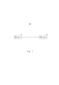
- FIG. 1 is a diagram illustrating a configuration example of a communication system according to a first embodiment
- FIG. FIG. 2 is a block diagram showing a configuration example of a RAN node according to the first embodiment.
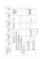
- FIG. 2 is a sequence diagram showing an example of the operation of the communication system according to the first embodiment.
- FIG. 7 is a sequence diagram showing an example of the operation of the communication system according to the second embodiment.
- FIG. 7 is a sequence diagram showing an example of the operation of the communication system according to the second embodiment.
- FIG. 3 is a diagram illustrating a configuration example of a communication system according to a third embodiment.
- FIG. 7 is a sequence diagram showing an example of the operation of the communication system according to the third embodiment.
- FIG. 7 is a sequence diagram showing an example of the operation of the communication system according to the fourth embodiment.
- FIG. 7 is a diagram illustrating a configuration example of a communication system according to a fifth embodiment.
- 12 is a sequence diagram showing an example of the operation of the communication system according to the fifth embodiment.
- FIG. 12 is a sequence diagram showing an example of the operation of the communication system according to the fifth embodiment.
- FIG. 7 is a sequence diagram showing an example of executing the transmission and reception shown in steps S1001 and 1002 using the Xn setup procedure.
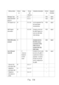
- An example of the IE configuration of the Xn SETUP REQUEST message in FIG. 10 is shown.
- An example of the IE configuration of the Xn SETUP REQUEST message in FIG. 10 is shown.
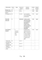
- FIG. 10 An example of the IE configuration of the Xn SETUP RESPONSE message in FIG. 10 is shown. An example of the IE configuration of the Xn SETUP RESPONSE message in FIG. 10 is shown. An example of the IE configuration of the Xn SETUP RESPONSE message in FIG. 10 is shown.
- FIG. 7 is a sequence diagram showing an example of executing the transmission and reception shown in steps S1001 and 1002 using another procedure.
- An example of the IE configuration of the Xn RAN AI/ML SETUP REQUEST message in FIG. 13 An example of the IE configuration of the Xn RAN AI/ML SETUP RESPONSE message in FIG. 13 is shown.
- FIG. 13 An example of the IE configuration of the Xn RAN AI/ML SETUP RESPONSE message in FIG. 13 is shown.
- FIG. 3 is a diagram illustrating an example of a Resource Status Reporting Initiation procedure used to configure a cell load report.
- FIG. 3 is a diagram illustrating an example of a Resource Status Reporting procedure used to obtain information regarding the load of a cell.
- FIG. 7 is a diagram showing an example of a RESOURCE STATUS REQUEST message transmitted in step S4001.
- FIG. 7 is a diagram showing an example of a RESOURCE STATUS REQUEST message transmitted in step S4001.
- FIG. 7 is a diagram showing an example of a RESOURCE STATUS REQUEST message transmitted in step S4001.
- FIG. 7 is a diagram showing an example of a RESOURCE STATUS UPDATE message transmitted in step S4003.
- Radio Resource Status IE It is a diagram showing an example of the configuration of Radio Resource Status IE. It is a diagram showing an example of the configuration of Radio Resource Status IE. It is a diagram showing an example of the configuration of Radio Resource Status IE. It is a diagram showing an example of the configuration of Radio Resource Status IE. It is a diagram showing an example of the configuration of Radio Resource Status IE. It is a figure which shows the example of a structure of Composite Available Capacity Group IE.
- FIG. 2 is a diagram illustrating a configuration example of Composite Available Capacity IE. It is a figure which shows the example of a structure of Cell Capacity Class Value IE. It is a diagram showing an example of the configuration of Capacity Value IE. It is a figure showing the example of composition of Slice Available Capacity IE.
- FIG. 3 is a sequence diagram showing an example of executing the transmission and reception shown in steps S1013 and S1015.
- FIG. 3 is a diagram illustrating a configuration example of an Xn RAN AI/ML ACTION REQUEST message.
- FIG. 3 is a diagram illustrating a configuration example of an Xn RAN AI/ML ACTION RESPONSE message.
- FIG. 3 is a diagram illustrating a configuration example of an Xn RAN AI/ML ACTION REQUEST message.
- FIG. 3 is a diagram illustrating a configuration example of an Xn RAN AI/ML ACTION RESPONSE message.
- FIG. 3 is a diagram illustrating a configuration example of an Xn RAN AI/ML ACTION RESPONSE message.
- FIG. 3 is a diagram illustrating a configuration example of an Xn RAN AI/ML ACTION REQUEST message.
- FIG. 3 is a diagram illustrating a configuration example of an Xn RAN AI/ML ACTION RESPONSE message.
- FIG. 2 is a block diagram showing a configuration example of a RAN node according to each embodiment.
- FIG. 1 is a diagram illustrating a configuration example of a communication system according to a first embodiment.
- the communication system 10A is, for example, a 5th generation mobile communication system (5G system).
- the 5G System is NR (New Radio Access), a fifth generation radio access technology.
- the communication system 10A is not limited to the 5th generation mobile communication system, and may be a different mobile communication system such as an LTE (Long Term Evolution) system, an LTE-Advanced system, or a 6th generation mobile communication system.
- the communication system 10A may be another radio communication system that includes at least a radio access network (RAN) node and user equipment (UE).
- the communication system 10A may be a communication system in which an ng-eNB (LTE evolved NodeB), which is a base station in LTE (Long Term Evolution), connects to a 5G core network (5GC) via an NG interface.
- ng-eNB LTE evolved NodeB
- the communication system 10A includes a RAN node 11 and a RAN node 12.
- RAN nodes 11, 12 are shown as RAN nodes 1, 2 in FIG. Note that although only two RAN nodes are illustrated in FIG. 1, the communication system 10A may include three or more RAN nodes.
- the RAN nodes 11 and 12 may be gNBs, for example.
- the gNB is a node that terminates the NR user plane and control plane protocols for the UE and connects to the 5GC via the NG interface.
- RAN nodes 11 and 12 may be ng-eNBs.
- the ng-eNB is a node that terminates E-UTRA (Evolved Universal Terrestrial Radio Access) user plane and control plane protocols for the UE and connects to the 5GC via the NG interface.
- the RAN nodes 11 and 12 may be a CU (Central Unit) in a C-RAN (cloud RAN) configuration, or may be a gNB-CU.
- the gNB-CU is a logical node that hosts the gNB's RRC (Radio Resource Control) protocol, SDAP (Service Data Adaptation Protocol) protocol, and PDCP (Packet Data Convergence Protocol) protocol.
- the gNB-CU is a logical node that hosts the RRC protocol and PDCP protocol of the en-gNB that controls the operation of one or more gNB-DUs (gNB-Distributed Units).
- gNB-CU terminates the F1 interface connected to gNB-DU.
- the RAN nodes 11 and 12 may be a CP (Control Plane) Unit or a gNB-CU-CP (gNB-CU-Control Plane).
- gNB-CU-CP is a logical node that hosts the RRC protocol and the control plane part of the gNB-CU's PDCP protocol for en-gNB or gNB.
- gNB-CU-CP terminates the E1 interface that connects to gNB-CU-UP (gNB-CU-User Plane) and the F1-C interface that connects to gNB-DU.
- gNB-CU-UP is a logical node that hosts the user plane part of the gNB-CU's PDCP protocol for en-gNB.
- gNB-CU-UP terminates the E1 interface that connects to gNB-CU-CP and the F1-U interface that connects to gNB-DU.
- the RAN nodes 11 and 12 may be eNBs or eNB-CUs. Furthermore, the RAN nodes 11 and 12 may be EUTRAN (Evolved Universal Mobile Telecommunications System (UMTS) Terrestrial Radio Access Network) nodes or NG-RAN (Next generation Radio Access Network) nodes.
- the EUTRAN node may be an eNB or en-gNB.
- the NG-RAN node may be a gNB or ng-eNB.
- the en-gNB provides NR user plane and control plane protocol termination for the UE, and operates as a secondary node in EN-DC (NR Dual Connectivity).
- the RAN nodes 11 and 12 establish an inter-node interface and communicate with each other via the inter-node interface.
- the inter-node interface may be an Xn interface (a network interface between NG-RAN nodes), an X2 interface, or another inter-node interface.
- the RAN nodes 11 and 12 each serve at least one cell.
- Each RAN node operates its own cell and connects and communicates with UEs located in each cell. Note that the way this cell is operated changes depending on the actions each RAN node performs.
- the RAN node 11 is coupled to an AI (Artificial Intelligence) model that is a management entity that manages the RAN node.
- This AI model may be, for example, an ML (Machine Learning) model, or a model using other types of programs or algorithms.
- the RAN node 11 functions as a gateway for the AI model to manage the RAN node 12, as described in detail below.
- the AI model may or may not manage RAN nodes other than the RAN node 12 (for example, the RAN node 11 and other RAN nodes) together with the RAN node 11.
- the AI model manages, for example, the actions of the RAN node 12, such as offloading of RAN nodes, UE HO, control related to communication energy saving, etc., but the management targets are limited to these. I can't.
- FIG. 2 is a block diagram showing an example of the configuration of a RAN node.
- the RAN nodes 11 and 12 are collectively referred to as a RAN node 100.
- the RAN node 100 includes a communication section 101 and a control section 102.
- the communication unit 101 and the control unit 102 may be software or modules whose processing is executed by a processor executing a program stored in a memory.
- the communication unit 101 and the control unit 102 may be hardware such as a circuit or a chip.
- the communication unit 101 connects and communicates with other RAN nodes and core network nodes included in the access network.
- the communication unit 101 also connects with the UE and performs communication. More specifically, the communication unit 101 receives various information from other RAN nodes, core network nodes, and UEs. Furthermore, the communication unit 101 transmits various information to other RAN nodes, core network nodes, and UE.
- the control unit 102 executes various processes of the RAN node 100 by reading and executing various information and programs stored in the memory.
- the control unit 102 performs processing according to any or all of setting information such as various information elements (IEs), various fields, and various conditions included in the message received by the communication unit 101.
- the control unit 102 is configured to be able to execute processing of multiple layers.
- the multiple layers may include a physical layer, a MAC (Media Access Control) layer, an RLC (Radio Link Control) layer, a PDCP layer, an RRC layer, a NAS (non Access Stratum) layer, and the like.
- RAN node 11 is a generic term for RAN nodes 11A-11B in Embodiment 1-2
- RAN node 12 is a generic term for RAN nodes 12A-12B in Embodiment 1-2.
- Embodiment 1-2 different operations performed by different RAN nodes will be explained.
- FIG. 3 is a sequence diagram showing an example of the operation of the communication system according to the first embodiment. Hereinafter, an example of the operation of the communication system 10A will be described using FIG. 3.
- step S1 the RAN node 11A transmits a first message to the RAN node 12A, including an IE indicating that the RAN node 11A is connected to an AI model that can manage other RAN nodes.
- RAN node 12A receives this first message.
- the RAN node 12A when the RAN node 11A sends the first message to the RAN node 12A, the RAN node 12A can learn that the RAN node 11A is connected to an AI model that can manage itself. can. By knowing this information, the RAN node 12A can be managed by the AI model. For example, the RAN node 12A may notify the AI model that it accepts being managed by the AI model, as described in paragraph 0039 below. By being managed by the AI model, the RAN node 12A can acquire information for operating the cell from the AI model. Therefore, the RAN node according to the first embodiment potentially contributes to collecting information useful for the RAN node to operate the cell.
- FIG. 4A is a sequence diagram illustrating an operation example of the communication system according to the second embodiment.
- an example of the operation of the communication system 10A in the second embodiment will be described using FIG. 4A.
- step S2 the RAN node 12B transmits a second message to the RAN node 11B, including an IE indicating that the RAN node 12B accepts being managed by the AI model connected to the RAN node 11B.
- RAN node 11B receives this second message.
- the RAN node 11B can learn that the RAN node 12B has accepted management by the AI model. This allows the AI model to manage the RAN node 12B via the RAN node 11B. Therefore, the RAN node according to the second embodiment contributes to collecting information useful for the RAN node to operate the cell.
- (2B) (2A) describes the operation in which the RAN node 12B transmits the second message to the RAN node 11B.
- this operation example and the operation described in paragraph 0036 may be combined.
- FIG. 4B is a sequence diagram showing different operational examples of the communication system according to the second embodiment.
- the RAN node 11B sends a first message including an IE indicating that the RAN node 11B is connected to an AI model that can manage other RAN nodes to the RAN node 12B. Send. RAN node 12B receives this first message.
- the RAN node 12B sends a second message including an IE indicating that the RAN node 12B accepts being managed by the AI model connected to the RAN node 11B. message to the RAN node 11B.
- the second message is a response to the first message.
- RAN node 11B receives this second message.
- the RAN node 11B sends the first message to the RAN node 12B, so that the RAN node 12B can learn that the RAN node 11B is connected to an AI model that can manage itself. Then, by the RAN node 12B transmitting the second message to the RAN node 11B, the RAN node 11B can know that the RAN node 12B has accepted management by the AI model. This allows the AI model to manage the RAN node 12B via the RAN node 11B. Therefore, the RAN node according to the second embodiment contributes to collecting information useful for the RAN node to operate the cell.
- FIG. 5 is a diagram showing a configuration example of a communication system according to the third embodiment.
- the communication system 10B is obtained by adding a RAN node 13 to the communication system 10A shown in FIG.
- the RAN nodes 11-13 establish inter-node interfaces and communicate with each other via the inter-node interfaces.
- the inter-node interface may be an Xn interface (a network interface between NG-RAN nodes), an X2 interface, or another inter-node interface.
- a detailed description of the RAN nodes 11 and 12 is the same as that shown in paragraphs 0026-0033, and will therefore be omitted. Further, detailed description of the RAN node 13 is also omitted since it is similar to the RAN node 12.
- the management entity that manages the RAN nodes 12 and 13 may be an AI model coupled to the RAN node 11, or may be another device. The other device may be, for example, the RAN node 11 or a device connected to the RAN node 11.
- RAN node 11 is a generic term for RAN nodes 11C-11D in Embodiment 3-4
- RAN node 12 is a generic term for RAN nodes 12C-12D in Embodiment 3-4
- RAN node 13 is a generic term for RAN nodes 11C-11D in Embodiment 3-4.
- Embodiment 3-4 different operations performed by different RAN nodes will be explained.
- FIG. 6 is a sequence diagram showing an example of the operation of the communication system according to the third embodiment.
- an example of the operation of the communication system 10B in the third embodiment will be described using FIG. 6.
- step S3 the RAN node 11C issues a request to the RAN node 12C and the RAN node 13C, which are set to be managed for a common action between the RAN node 12C and the RAN node 13C, to execute the action.
- RAN nodes 12C and 13C receive the third message.
- Examples of "common actions" that are managed by the RAN node 12C and the RAN node 13C are as shown in paragraph 0030, and examples include offloading of RAN nodes, HO of UE, control regarding communication energy saving, etc.
- the objects of management are not limited to these. Note that when the management entity is an AI model, a management relationship may be established between the AI model and the RAN nodes 12C and 13C by, for example, the process shown in paragraph 0042.
- the RAN node 11C sends a message to the RAN nodes 12C and 13C to be managed to cause them to execute an action to be managed. This enables the RAN nodes 12C and 13C to execute actions. Therefore, the RAN node according to the third embodiment contributes to collecting information useful for the RAN node to operate the cell.
- FIG. 7 is a sequence diagram showing an example of the operation of the communication system according to the fourth embodiment.
- an example of the operation of the communication system 10B in the fourth embodiment will be described using FIG. 7.
- step S4 the RAN node 12D executes the action requested to be performed on the RAN node 12D and the RAN node 13D that are set to be managed for a common action between the RAN node 12D and the RAN node 13D.
- a fourth message containing the relevant IE is sent towards RAN node 11D.
- RAN node 13D also transmits this fourth message toward RAN node 11D.
- RAN node 11D receives the fourth message from RAN nodes 12D and 13D. Examples of "common actions" that are managed by the RAN node 12D and RAN node 13D are shown in paragraph 0030, and examples include offloading of RAN nodes, UE HO, control regarding communication energy saving, etc.
- IE related to the execution of an action includes, for example, the fact that the action was executed, the type of the action, the result of the action, the identification information of the cell related to the action, and the amount of the target for which the action was performed. It may also be an IE that indicates Note that when the management entity is an AI model, a management relationship may be established between the AI model and the RAN nodes 12D and 13D by, for example, the process shown in paragraph 0042.
- the RAN nodes 12D and 13D transmit a message containing the execution result of the requested action to the RAN node 11D. This allows the RAN nodes 12D and 13D to receive management from the management entity based on the execution results. Therefore, the RAN node according to the fourth embodiment contributes to collecting information useful for the RAN node to operate the cell.
- Embodiment 5 provides a specific example of the communication system shown in Embodiments 1-4.
- FIG. 8 is a diagram showing a configuration example of a communication system according to the fifth embodiment.
- the communication system 20 is a 5G system and includes a RAN node 21, a RAN node 22, a RAN node 23, and a RAN AI/ML model 24.
- RAN nodes 21-23 are NG-RAN nodes and are gNBs or gNB-CUs as described in paragraph 0026.
- RAN nodes 21-23 are shown in FIG. 8 as RAN nodes 1-3.
- RAN node 22 provides cells 25A-25F. Specifically, the RAN node 22 operates cells 25A-25F, connects and communicates with UEs in each cell. In this example, the RAN node 22 is connected to a UE 30A in a cell 25A and a UE 30B in a cell 25F. Also, in FIG. 8, the RAN node 23 provides cells 25G-25L. Specifically, the RAN node 23 operates cells 25G-25L, connects and communicates with UEs in each cell. Although not shown in FIG. 8, the RAN node 21 also provides and operates cells in the same way as the RAN nodes 22 and 23.
- the RAN nodes 21-23 establish an inter-node Xn interface and communicate with each other via the inter-node interface.
- the configuration example of the RAN nodes 22-23 is similar to the configuration example of the RAN node shown in FIG. 2, and the description thereof will be omitted.
- a cell 25E provided by the RAN node 22 is adjacent to cells 25G and 25H provided by the RAN node 22. Furthermore, cell 25F provided by RAN node 22 is also adjacent to cells 25G and 25H. For this reason, hereinafter, RAN node 23 may also be referred to as an adjacent RAN node of RAN node 22. Since the above relationship between adjacent cells exists, traffic offloading or handover processing can be performed between the cell 25E or 25F and the cell 25G or 25H, as shown by the arrow in FIG.
- the RAN node 22 and the RAN node 23 perform the following based on at least one of the settings made in each device or the measurement report transmitted from the UE located in the cell provided by the node. Recognize mutual adjacency. That is, the RAN node 22 recognizes that cells 25E and 25F are adjacent to cells 25G and 25H, and the RAN node 23 recognizes that cells 25G and 25H are adjacent to cells 25E and 25F. do.
- the RAN node 22, the RAN node 23, and the UE 30B can execute a handover procedure so that the UE 30B is handed over from the cell 25F provided by the RAN node 22 to the cell 25H provided by the RAN node 23.
- UE 30B communicates with RAN node 23 providing cell 25H.
- the cell 25F that is the movement source of the UE 30B may be called a source cell
- the cell 25H that is the movement destination may be called a target cell.
- RAN node 22 may be referred to as a source RAN node
- RAN node 23 may be referred to as a target RAN node.
- the cell 25H is the serving cell after handover, and the cell 25F may be referred to as the last serving cell.
- the RAN AI/ML model 24 is coupled to the RAN node 21 and can communicate with each device via the RAN node 21.
- the RAN AI/ML model 24 may be placed within the RAN node 21 or placed in a device external to the RAN node 21, and when that device is connected to the RAN node 21, the RAN AI/ML model 24 is connected to the RAN node 21. may be done.
- This RAN AI/ML model 24 manages a certain area including a plurality of RAN nodes 22 and 23. Note that RAN nodes other than the RAN nodes 22 and 23 (for example, the RAN node 21) may be included as management targets.
- the RAN node 21 coupled with the RAN AI/ML model 24 may be an AI-compatible RAN node.
- An AI-enabled RAN node may be referred to as a RAN node equipped with an AI function, or may be referred to as a RAN node equipped with an AI function.
- an AI-enabled RAN node may be referred to as an AI-enhanced RAN node.
- "AI-enabled RAN node,” “RAN node equipped with AI functionality,” and “RAN node equipped with AI functionality” refer to It is a RAN node that uses an AI/ML model for communication control.
- the RAN node 21 may operate as a RAN node equipped with an AI function, for example, by communicating with a RAN intelligence device (not shown) and using an AI/ML model held by the RAN intelligence device.
- the RAN node 21 may operate as a RAN node equipped with an AI function by having the function of a RAN intelligence device and using an AI/ML model held by the RAN intelligence device.
- the RAN AI/ML model 24 may acquire an AI/ML model from the RAN intelligence device, and the RAN node 21 may use the AI/ML model to operate as a RAN node equipped with an AI function. .
- the RAN intelligence device is, for example, a control device that is responsible for making the RAN intelligent, and is a control device that performs communication control of the RAN.
- the RAN intelligence device may be, for example, a RAN Intelligent Controller (RIC) defined by O-RAN (Open-RAN).
- RIC RAN Intelligent Controller
- the RAN intelligence device performs mobility management such as policy management, analysis of various RAN information, AI-based function management, load balancing for each UE, radio resource management, QoS (Quality of Service) management, and handover control. conduct.
- the RAN AI/ML model 24 executes LB (Load Balancing) or UE HO, which will be described later, between the RAN nodes 22 and 23. This enables locally centralized LB (LB) control.
- LB Load Balancing
- the RAN AI/ML model 24 has an AI function that uses the RAN node 21 as a gateway to perform communication control based on information received from other devices (other network elements) including UEs such as RAN nodes 21-23 and UE 30. Be prepared.
- the RAN AI/ML model 24 includes a machine learning (ML) function as an example of the AI function.
- the AI/ML function executes load offloading or HO performance optimization processing, but the executed processing is not limited to this, and for example, control regarding communication energy saving may be executed.
- the communication unit 101 of the RAN node 21 connects with the RAN intelligence device and performs communication. conduct.
- the communication unit 101 may communicate with the RAN intelligence device, and the control unit 102 may be able to use the AI/ML model held by the RAN intelligence device.
- the communication unit 101 may communicate with the RAN intelligence device and acquire the AI/ML model held by the RAN intelligence device.
- the control unit 102 may perform RAN communication control based on the information received by the communication unit 101 using an AI/ML model. Specifically, the control unit 102 inputs the information received by the communication unit 101 into the AI/ML model, and inputs various information related to RAN communication control and/or various information related to UE communication control. You may also output it. The control unit 102 may control the RAN and the UE by transmitting such various information to the RAN node and the UE. The control unit 102 may perform machine learning on the AI/ML model based on the information received by the communication unit 101. Note that "learning,” “training,” and “training” in the present disclosure have the meaning of automatically adjusting parameters of an AI/ML model and constructing the model.
- Embodiment 5 provides a deployment scenario where the AI functionality at the RAN node serves only one gNB or gNB-CU, thereby providing a fully distributed and autonomous solution.
- the AI functionality at the RAN node may serve multiple gNBs or gNB-CUs.
- the CN (Core Network) node 40 in FIG. 8 is an NWDAF (Network Data Analytic Function) in this example.
- the CN node 40 has a function of collecting and analyzing various data obtained on the network in 5GC.
- the OAM (Operations, Administration and Management) device 50 has an operation management function for the communication system 20.
- the RAN node 21 is connected to the CN node 40 and the OAM device 50.
- FIGS. 9A and 9B are sequence diagrams showing an example of the operation of the communication system according to the fifth embodiment.
- the RAN nodes 21-23, CN node 40, and OAM device 50 establish an inter-node interface with each other.
- the order of each step shown below is not limited unless specified otherwise.
- the presence or absence of each step or the presence or absence of detailed processing of each step can be changed as appropriate.
- the RAN node 21 submits a proposal regarding becoming a management target of the RAN AI/ML model 24 in order to establish a management relationship between the RAN AI/ML model 24 and the managed RAN nodes 22 and 23.
- a message containing the information (hereinafter also referred to as MANAGEMENT RELATIONSHIP REQUEST) is sent to the RAN nodes 22 and 23.
- RAN nodes 22, 23 receive the message.
- the message sent by the RAN node 21 to the RAN nodes 22 and 23 is sent via offload or UE HO in order to establish a management relationship between the RAN AI/ML model 24 and the managed RAN nodes 22 and 23.
- the message may include a proposal regarding at least one of the actions to be managed.
- step S1002 the RAN nodes 22 and 23 send a message (hereinafter also referred to as MANAGEMENT RELATIONSHIP RESPONSE) to the RAN node 21 as a reply to the MANAGEMENT RELATIONSHIP REQUEST, indicating that they accept the proposal regarding becoming a management target.
- MANAGEMENT RELATIONSHIP RESPONSE a message
- Send to. RAN node 21 receives the message.
- the Xn setup procedure indicates a procedure for setting up an Xn interface between RAN nodes (setting procedure for communication settings), and complies with section 8.4.1 of Non-Patent Document 1.
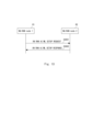
- FIG. 10 is a sequence diagram showing an example of executing the transmission and reception shown in steps S1001 and 1002 using the Xn setup procedure.
- NG-RAN node R1 (corresponding to RAN node 21) informs NG-RAN node R2 (corresponding to RAN nodes 22 and 23) that it will be managed by the RAN AI/ML model 24.
- the Xn SETUP REQUEST message may include a proposal regarding at least one of offloading and UE HO actions to be managed.
- the NG-RAN node R2 transmits an Xn SETUP RESPONSE message to the NG-RAN node R1, indicating that it accepts the proposal regarding becoming a management target.
- FIGS. 11A and 11B show an example of the configuration of the IE of the Xn SETUP REQUEST message in FIG. 10.
- the Xn SETUP REQUEST message shown in FIGS. 11A and 11B includes the IE of the Xn SETUP REQUEST message described in section 9.1.3.1 of Non-Patent Document 1.
- a RAN AI/ML setup proposal IE (RAN AI/ML SETUP PROPOSAL) may be added to the Xn SETUP REQUEST message as an option.
- the RAN AI/ML setup proposal IE is the underlined IE in FIG. 11A.
- the RAN AI/ML setup proposal IE indicates that the RAN node 21 that sent this message is connected to a RAN AI/ML model that can manage other RAN nodes.
- FIGS. 12A to 12C show examples of IE configurations of the Xn SETUP RESPONSE message in FIG. 10.
- the Xn SETUP RESPONSE messages shown in FIGS. 12A to 12C include the IE of the Xn SETUP RESPONSE message described in section 9.1.3.2 of Non-Patent Document 1.
- a RAN AI/ML setup response IE (RAN AI/ML SETUP REPLY) may be added to the Xn SETUP RESPONSE message as an option.
- the RAN AI/ML setup response IE is the underlined IE in FIG. 12A.
- the RAN AI/ML setup response IE is an IE that can take a binary value of TRUE or FASLE.
- this IE is TRUE, it indicates that the RAN node R2 accepts management by the RAN AI/ML model, while if it is FASLE, it indicates that the RAN node R2 rejects the management by the RAN AI/ML model.
- the formats of the RAN AI/ML setup proposal IE and the RAN AI/ML setup response IE are not limited to the examples shown above.
- FIG. 13 is a sequence diagram showing an example of executing the transmission and reception shown in steps S1001 and 1002 using another procedure.
- NG-RAN node R1 (corresponding to RAN node 21) informs NG-RAN node R2 (corresponding to RAN nodes 22 and 23) that it will be managed by the RAN AI/ML model 24.
- the Xn RAN AI/ML SETUP REQUEST message includes a proposal for NG-RAN node R2 (corresponding to RAN nodes 22 and 23) to be managed for at least one of offloading and UE HO actions. It may also be a message.
- the NG-RAN node R2 transmits an Xn RAN AI/ML SETUP RESPONSE message to the NG-RAN node R1, indicating that it accepts the proposal regarding becoming a management target.
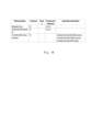
- FIG. 14 shows an example of the configuration of the IE of the Xn RAN AI/ML SETUP REQUEST message in FIG. 13.
- the Xn RAN AI/ML SETUP REQUEST message shown in FIG. 14 includes at least the message type, global NG-RAN node ID, and Xn RAN AI/ML setup proposal IE as IEs.
- the global NG-RAN node ID indicates the ID of the source RAN node.
- the Xn RAN AI/ML setup proposal IE has the same contents as the RAN AI/ML setup proposal IE in FIG. 11A.
- the message type IE is the IE indicating the message type described in section 9.2.3.1 of Non-Patent Document 1
- the IE of the global NG-RAN node ID is the IE described in Non-Patent Document 1. This IE is used to globally identify NG-RAN nodes, as described in section 9.2.2.3.
- the Presence of each IE is shown as "M" (Mandatory).
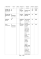
- FIG. 15 shows an example of the configuration of the IE of the Xn RAN AI/ML SETUP RESPONSE message in FIG. 13.
- the Xn RAN AI/ML SETUP RESPONSE message shown in FIG. 15 includes, as IEs, a message type, a global NG-RAN node ID, and an IE of the Xn RAN AI/ML setup response.
- the global NG-RAN node ID indicates the ID of the source RAN node.
- the IE of the Xn RAN AI/ML setup response is an IE with the same content as the RAN AI/ML setup response IE in FIG. 12A.
- the message type IE is the IE indicating the message type described in section 9.2.3.1 of Non-Patent Document 1
- the IE of the global NG-RAN node ID is the IE described in Non-Patent Document 1. This IE is used to globally identify NG-RAN nodes, as described in section 9.2.2.3. In the example of FIG. 15, the Presence of each IE is indicated as "M".
- step S1003 the UE located in each cell of the RAN nodes 22 and 23 periodically performs measurement.
- This measurement concerns parameters related to load offloading and HO decisions.
- This parameter may include, for example, quality information measured for the cell of the RAN node 22 or 23 to which the UE belongs.
- the quality information may be the value of a reference signal received from a source cell (source RAN node) or a target cell (target RAN node).
- the quality information may also be the value of a reference signal received from a source cell (source RAN node) or a target cell (target RAN node) in response to the occurrence of an unintended event.
- the reference signal value may include at least one of RSRP (Reference Signal Received Power), RSRQ (Reference Signal Received Quality), or SINR (Signal to Interference plus Noise Ratio).
- RSRP Reference Signal Received Power
- RSRQ Reference Signal Received Quality
- SINR Signal to Interference plus Noise Ratio
- a specific example of "quality information measured for the cell to which this UE belongs” includes both the quality information (RSRP, etc.) of the cell where the UE is (in which it resides) and the quality information (RSRP, etc.) of the neighboring cell. May include.
- the UE 30B can measure both the quality information of the cell 25F and the quality information of the adjacent cell 25H or 25G in step S1003.
- the UE transmits the results of the parameter measurements performed, for example as a measurement report, to the RAN node 22 or 23 to which the UE belongs.
- step S1004 the RAN nodes 22 and 23 to be managed transmit the measurement report information obtained in step S1003 to the RAN AI/ML model 24 via the RAN node 21.
- This information may be sent using the procedures described in sections 8.4.10 and 8.4.11 of the Non-Patent Document 1. The details will be explained below.
- FIG. 16A is a diagram illustrating the Resource Status Reporting Initiation procedure described in section 8.4.10 of Non-Patent Document 1, which is used to transmit a cell load report to other RAN nodes.
- a RESOURCE STATUS REQUEST message is sent from NG-RAN node R1 to NG-RAN node R2 in step S4001, and in response, NG-RAN node R2 sends a RESOURCE STATUS RESPONSE message to NG-RAN node R2 in step S4002.
- the RESOURCE STATUS REQUEST message in step S4001 can include a parameter (eg, an indicator) that instructs the UE to report the load information measured in step S1003.
- FIG. 16B shows the Resource Status Reporting procedure described in section 8.4.11 of Non-Patent Document 1, which is used to obtain information regarding the cell load.
- a RESOURCE STATUS UPDATE message is sent from the NG-RAN node R2 to the NG-RAN node R1.
- This RESOURCE STATUS UPDATE message may be used as an example of the message sent in step S1004.
- the RAN node 21 acquires load information from the RAN nodes 22 and 23.
- FIGS. 17A-17C are diagrams showing the RESOURCE STATUS REQUEST message sent in step S4001. This RESOURCE STATUS REQUEST message is described in section 9.1.3.18 of Non-Patent Document 1.
- the structure of the IE below, shown in Figure 17B, defines the characteristics of which cells are reported. Note that ">" in the structure shown in the specification and drawings indicates a data hierarchy. Cell To Report List >Cell To Report Item >>Cell ID ... The following two options can be considered as the cells targeted for this report.
- Option 1 In option 1, only cells of the NG-RAN node R2 that are adjacent to cells of other RAN nodes that are managed together with the NG-RAN node R2 are to be reported.
- the RAN AI/ML model 24 only manages LB decisions within the cell to be reported, and LB decisions in other cells are managed autonomously by each RAN node.
- cells 25E and 25F are reported in the RAN node 22, and cells 25G and 25H are reported in the RAN node 23.
- the RAN AI/ML model 24 manages LB decisions in cells 25E to 25H, while the RAN node 22 manages LB decisions in cells 25A to 25D, and the RAN node 23 manages LB decisions in cells 25I to 25L. do.
- all cells 25A to 25F in the RAN node 22 and all cells 25G to 25L in the RAN node 23 are to be reported.
- the RAN AI/ML model 24 then manages LB decisions within the cells 25A to 25L.
- Option 1 decentralizes the management of cells in each RAN node, while Option 2 manages all cells collectively by the RAN AI/ML model 24. Management will be more efficient. However, in option 2, signals are transmitted from RAN nodes 22, 23 to RAN node 21 for all cells, whereas in option 1, signals are transmitted from RAN nodes 22, 23 to RAN node 21. Since the number of cells that can be used is limited, option 1 reduces the amount of data communication required.
- a cell of NG-RAN node R2 that includes a cell adjacent to a cell of another RAN node to be managed together with NG-RAN node R2, and a preset cell of NG-RAN node R2.
- Some cells of RAN node R2 may be subject to reporting.
- FIG. 18 is a diagram showing the RESOURCE STATUS UPDATE message sent in step S4003. This RESOURCE STATUS UPDATE message is described in section 9.1.3.21 of Non-Patent Document 1. Some IEs shown in FIG. 18 will be described below.
- the Radio Resource Status IE shown in FIG. 18 is the Radio Resource Status IE defined in section 9.2.2.50 of Non-Patent Document 1 for R-16. However, the Radio Resource Status IE in R-17 as of October 2021 may be further added.
- FIGS. 19A to 19D are diagrams showing configuration examples of such a Radio Resource Status IE.
- This Radio Resource Status IE is used to report the following information.
- - Usage amount of at least one of DL (Downlink) / UL (UPlink), GBR (Guaranteed Bit Rate), non-GBR, or total PRB (Physical Resource Block) usage for each beam in each cell of each RAN node At least one of the following: DL/UL usage per slice in each cell of each RAN node, GBR, non-GBR, or total PRB usage
- the Composite Available Capacity Group IE shown in FIG. 18 is the Composite Available Capacity Group IE defined in section 9.2.2.51 of Non-Patent Document 1 for R-16. However, the Composite Available Capacity Group IE in R-17 as of October 2021 may be further added.
- FIG. 20 is a diagram showing a configuration example of such a Composite Available Capacity Group IE.
- This group indicates Composite Available Capacity in DL/UL/SUL (Supplementary Uplink).
- a configuration example of each Composite Available Capacity IE is shown in FIG. 21.
- Composite Available Capacity IE includes Capacity Value IE and may also optionally include Cell Capacity Class Value IE.
- FIG. 22 is a diagram showing a configuration example of the Cell Capacity Class Value IE.
- FIG. 23 is a diagram showing a configuration example of the Capacity Value IE.
- the Capacity Value IE is used to report the following information: ⁇ Capacity of DL, UL and SUL, >capacity per cell for requested cells and beams, and >capacity per beam of each cell
- the Slice Available Capacity IE shown in FIG. 18 is defined in section 9.2.2.55 of Non-Patent Document 1, and an example of its configuration is shown in FIG. 24. This is used to report the capacity per slice DL/UL per PLMN (Public Land Mobile Network) per cell for the requested cells and slices.
- PLMN Public Land Mobile Network
- FIG. 25 is a diagram showing a configuration example of the Number of Active UEs IE shown in FIG. 18.
- the Mean Number of Active UEs IE shown in FIG. used to report numbers.
- FIG. 26 is a diagram showing a configuration example of the RRC Connections IE shown in FIG. 18.
- This RRC Connections IE is an RRC Connections IE defined in section 9.2.2.56, section 9.2.2.57, and section 9.2.2.58 of Non-Patent Document 1, and has a Number of RRC Connections IE and an Available RRC Connection Capacity Value IE.
- FIG. 27A is a diagram illustrating a configuration example of the Number of RRC Connections IE
- FIG. 27B is a diagram illustrating a configuration example of the Available RRC Connection Capacity Value IE.
- the RRC Connections IE is used to report the number of used and available RRC connections per cell for the requested cell.
- the information that can be input and used by the RAN AI/ML model 24, which is the LB algorithm is, for example, as follows.
- the CN node 40 transmits network information to the RAN AI/ML model 24 via the RAN node 21.
- Network information can be implemented, for example, via an existing NWDAF subscription service.
- the network information transmitted from the CN node 40 may include, for example, at least one of the following information.
- the RAN node 21 may acquire such network information from a device on the 5GC, not limited to the CN node 40.
- step S1006 the OAM device 50 transmits network information to the RAN AI/ML model 24 via the RAN node 21.
- the network information transmitted from the OAM device 50 may include area information such as the cell where the UE is located, traffic information, and statistical information.
- the statistical information may include statistical information regarding handover, and statistical information regarding call processing such as call connection and call disconnection. Note that the order in which steps S1004, S1005, and S1006 are performed is not limited to that described above.
- the RAN AI/ML model 24 performs initial and periodic training of the RAN AI/ML model based on the information received in steps S1004 to S1006.
- the RAN AI/ML model 24 can make LB decisions for selected cells of the managed RAN nodes 22 and 23. For example, either option 1 or option 2 shown in paragraphs 0087 to 0091 can be applied to the selected cell.
- the LB decision is a decision regarding the LB HO between selected cells of the managed RAN nodes. In this way, the RAN AI/ML model 24 can be configured.
- Any known model or new model can be used as the RAN AI/ML model 24. Examples of various known models and their implementation methods are described in Non-Patent Documents 5 to 7.
- steps S1008, S1009, S1010, and S1011 perform the same processing as steps S1003, S1004, S1005, and S1006, respectively, and therefore the description thereof will be omitted.
- This allows the RAN AI/ML model 24 to collect information for determining LB HO.
- step S1012 the RAN AI/ML model 24 generates a LB decision for the selected cell of the managed RAN nodes 22, 23 according to the input. As described above, for example, either option 1 or option 2 shown in paragraphs 0087 to 0091 can be applied to the selected cell. Further, the LB decision is a decision regarding the LB HO between selected cells of the RAN nodes to be managed.
- step S1013 the RAN node 21 transmits an LB HO request to the RAN nodes 22 and 23 based on the LB decision generated by the RAN AI/ML model 24.
- the RAN nodes 22 and 23 execute LB HO in step S1014.
- step S1015 the RAN nodes 22 and 23 transmit an LB HO response including the fact that the action LB HO has been executed and the result of the action to the RAN AI/ML model 24 via the RAN node 21.
- the message sending and receiving procedures in steps S1013 and S1015 are defined in a general manner that can be applied not only to the LB HO action according to this embodiment but also to any action such as energy saving control. Ru.
- the message transmitted in step S1013 is defined as "Xn RAN AI/ML ACTION REQUEST”
- the message transmitted in step S1015 is defined as "Xn RAN AI/ML ACTION RESPONSE.”
- FIG. 28 is a sequence diagram showing an example of transmitting and receiving the Xn RAN AI/ML ACTION REQUEST message and the Xn RAN AI/ML ACTION RESPONSE message in steps S1013 and S1015.
- an Xn RAN AI/ML ACTION REQUEST message is transmitted from NG-RAN node R1 (RAN node 21) to NG-RAN node R2 (RAN nodes 22, 23) in step S5001.
- the NG-RAN node R2 sends an Xn RAN AI/ML ACTION RESPONSE message to the NG-RAN node R1 in step S5002.
- FIG. 29 shows a configuration example of the Xn RAN AI/ML ACTION REQUEST message in (1) selective IE.
- the underlined IE in FIG. 29 is an IE newly proposed in this embodiment.
- Action type IE in FIG. 29 is an indicator indicating the type of requested action. As shown in paragraph 0112, there are two possible types of requested actions: "loadOffload” and "UEHO". If either of these two actions is specified as the action type, Actor Cell CGI (Cell Global Identity) IE (Actor Cell CGI IE) and Neighbor Cell CGI IE (Negibour Cell CGI IE) are used as identification information. Note that the actor cell is a cell to which the load in the cell is offloaded or to which a UE residing in the cell is handed over.
- Actor Cell CGI Cell Global Identity
- IE Vector Cell CGI IE
- Neighbor Cell CGI IE Neighbor Cell CGI IE
- the action type is "loadOffload”
- the percentage of the actor cell's current load that is offloaded to the specified neighboring cell is displayed as the "Percentage of Load to Offload” IE (indicator). shown.
- the current load of the actor cell may be, for example, the last reported or predicted one.
- the action type is "UEHO”
- the number of UEs to be handed over from the actor cell to the designated neighboring cell is indicated as an IE (indicator) of "Number of UEs to HO”.
- the active UE count may be used to generate the UE count for the HO value.
- the indicator indicating the amount of load to be offloaded is not limited to Percentage of Load to Offload IE, and other types of indicators may be used.
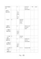
- FIG. 30 shows a configuration example of the Xn RAN AI/ML ACTION RESPONSE message in (1) selective IE.
- the NG-RAN node R2 After the NG-RAN node R2 performs an action in response to the Xn RAN AI/ML ACTION RESPONSE, it sends this message indicating that the action has been taken.
- this example configuration of Xn RAN AI/ML ACTION RESPONSE may include an Action Result IE that indicates the result of executing the action. For example, "ActionPerformed" indicating that the action was successful, or "ActionFailed" indicating that the action failed is reported as the Action Result IE.
- the Action Result IE can also have other values indicating why the action failed.
- the "Percentage of Load Offloaded" and “Number of UEs HOed” IEs can be used to report the results of actions in more detail.
- the action type is "loadOffload”
- the percentage of the load of the actor cell before the action that is offloaded to the specified neighboring cell is shown as the “Percentage of Load Offloaded” IE.
- the action type is "UEHO”
- the number of UEs handed over from the actor cell to the designated neighboring cell is shown as the "Number of UEs HOed” IE.
- Presence of each IE regarding Action Result is described as "O", but the presence of any part or all of these IEs is Presence may be "M”.
- a Cause IE (indicator) indicating the reason for the action result may be added to the Xn RAN AI/ML ACTION RESPONSE.
- a Cause IE indicator
- a Cause IE indicator indicating the reason for the action result
- RAN node R2 attempts to perform the action, cell 1 has the ability to perform an HO to cell 2 because the signal level of cell 2 for the UE located in cell 1 is lower than a predetermined threshold.
- Cause IE can be used to indicate such reasons.
- a Cause IE may be added to the Xn RAN AI/ML ACTION RESPONSE when the action fails and the value of the Action Result IE is ActionFailed.
- the Cause IE may be added to the Xn RAN AI/ML ACTION RESPONSE when the action succeeds and the value of the Action Result IE is ActionPerformed, rather than when the action fails.
- the Cause IE may indicate why the action was successful.
- the Cause IE can be used to indicate the reason for the action result, whether the action is successful or unsuccessful (i.e., the value of the Action Result IE is ActionPerformed or ActionFailed). May be added to ML ACTION RESPONSE.
- Action Result IE is provided for the Xn RAN AI/ML ACTION RESPONSE, and a Cause IE is not provided, while if the action fails, the Xn A Cause IE is provided for RAN AI/ML ACTION RESPONSE, but an Action Result IE does not need to be provided. If the action is successful, the value of Action Result IE will be ActionPerformed. On the other hand, if the action fails, setting the Cause IE essentially means ActionFailed, so it is no longer necessary to set the Action Result IE.
- FIG. 31 shows a configuration example of the Xn RAN AI/ML ACTION REQUEST message in the (2) CHOICE structure.
- FIGS. 32A and 32B show a configuration example of the Xn RAN AI/ML ACTION RESPONSE message in the (2) CHOICE structure.
- the underlined IEs in FIGS. 31 and 32A-32B are newly proposed IEs in this embodiment.
- loadOffload IE may include Percentage of Load to Offload IE
- UEHO IE may include Number of UEs to HO IE.
- the explanation of these IEs is the same as (1) the Xn RAN AI/ML ACTION REQUEST message in the selective IE, so the explanation will be omitted.
- CHOICE Action Type IE is further added, and either loadOffload IE or UEHO IE is added below it depending on the type of action.
- the difference is that it is defined as
- the lower layer of the loadOffload IE may include the Percentage of Load Offloaded IE
- the lower layer of the UEHO IE may include the Number of UEs HOed IE.
- the explanations of these IEs are omitted because they are the same as (1) the Xn RAN AI/ML ACTION RESPONSE message in the selective IE.
- a Cause IE may be added to (2) Xn RAN AI/ML ACTION RESPONSE in the CHOICE structure.
- the Cause IE may be added to the Xn RAN AI/ML ACTION RESPONSE message when the action is successful and/or unsuccessful, as described in paragraph 0120. Or, as described in paragraph 0121, if the action is successful, an Action Result IE is provided for the Xn RAN AI/ML ACTION RESPONSE, and a Cause IE is not provided, but if the action fails: , a Cause IE is provided for Xn RAN AI/ML ACTION RESPONSE, and an Action Result IE may not be provided.
- FIG. 33 shows a configuration example of the Xn RAN AI/ML ACTION REQUEST message in (3) conditionally existing IE.
- FIG. 34 shows a configuration example of the Xn RAN AI/ML ACTION RESPONSE message in (3) conditionally existing IE.
- the underlined IEs in FIGS. 33 and 34 are newly proposed IEs in this embodiment.
- the Presence of Percentage of Load to Offload IE and Number of UEs to HO IE is "C" (Conditional).
- the Percentage of Load to Offload IE exists when the action type is "loadOffload”
- the Number of UEs to HO IE exists when the action type is "UEHO”.
- the explanation of other IEs is the same as that of the Xn RAN AI/ML ACTION REQUEST message in (1) and (2), so the explanation will be omitted.
- the Presence of the IE of the adjacent cell CGI is described as “O”, but it may be "M”.
- the Cause IE may be added to the Xn RAN AI/ML ACTION RESPONSE message when the action is successful and/or unsuccessful, as described in paragraph 0120. Or, as described in paragraph 0121, if the action is successful, an Action Result IE is provided for the Xn RAN AI/ML ACTION RESPONSE, and a Cause IE is not provided, but if the action fails: , a Cause IE is provided for Xn RAN AI/ML ACTION RESPONSE, and an Action Result IE may not be provided.
- the Presence of the IE of the adjacent cell CGI is described as “O”, but it may be "M”.
- step S1014 the RAN nodes 22, 23 receive the request from the actor cell indicated in the Execute LB HO to neighboring cells.
- the RAN AI/ML model 24 does not have to select a specific UE for the LB HO.
- the approximate number of UEs targeted for HO may be indicated as a percentage of the total cell load or as a number of UEs.
- the UE targeted for HO may be specified using another method.
- the RAN nodes 22 and 23 determine the LB HO taking into account the signal level measurements of the particular UE relative to the source cell and potential neighboring cells, traffic characteristics, QoS (Quality of Service) requirements, and slices of the particular UE.
- the UE can be autonomously selected for the purpose.
- step S1015 the RAN nodes 22 and 23 execute an action on the RAN AI/ML model 24 via the RAN node 21 using the Xn RAN AI/ML ACTION REQUEST message. and the results of the actions.
- the RAN AI/ML setup indicates that the RAN node 21 is connected to the RAN AI/ML model 24 that can manage the RAN nodes 22 and 23.
- An Xn SETUP REQUEST message including the proposal IE (or an Xn RAN AI/ML SETUP REQUEST message including the Xn RAN AI/ML setup proposal IE) is transmitted to the RAN nodes 22 and 23. Therefore, the RAN nodes 22 and 23 can know that the RAN node 21 is connected to the RAN AI/ML model 24 that can manage itself. By knowing this information, the RAN nodes 22 and 23 can be managed by the RAN AI/ML model 24.
- the RAN nodes 22, 23 may notify the AI model that they accept being managed by the RAN AI/ML model 24.
- the RAN nodes 22 and 23 can acquire information for operating the cell from the AI model. Therefore, it potentially contributes to gathering useful information for the RAN nodes 22, 23 to operate the cell.
- the RAN node 22 receives a RAN AI/ML setup response indicating that the RAN node 22 accepts that the RAN AI/ML model 24 connected to the RAN AI/ML model 24 connects to the RAN AI/ML setup response IE.
- a SETUP RESPONSE message (or an Xn RAN AI/ML SETUP RESPONSE message including the Xn RAN AI/ML setup response IE) is sent to the RAN node 21.
- the RAN node 23 can also perform similar processing. This allows the RAN AI/ML model 24 to manage the RAN nodes 22 and 23 via the RAN node 21. Therefore, it contributes to gathering information useful for the RAN nodes 22 and 23 to operate the cell.
- the RAN AI/ML model 24 may manage common actions regarding the RAN nodes 22 and 23. This allows the RAN nodes 22 and 23 to collect information useful for operating the cell from the perspective of performing common actions.
- the RAN node 22 is an adjacent RAN node of the RAN node 23, and the common action may be at least one of offloading and UE HO.
- the RAN nodes 22 and 23 can collect information useful for operating the cell from the perspective of performing offloading or UE HO.
- the Xn RAN AI/ML SETUP REQUEST message is sent to the RAN nodes 22 and 23 even after the configuration message (Xn SETUP REQUEST message) regarding the communication settings between the RAN node 21 and the RAN nodes 22 and 23 is sent. can be sent. This allows the RAN AI/ML model 24 to manage the RAN nodes 22 and 23 even after the Xn interface is configured.
- the Xn RAN AI/ML SETUP RESPONSE message is not sent to the RAN node 21 even after the setting message (Xn SETUP RESPONSE message) regarding the communication settings between the RAN node 21 and the RAN nodes 22 and 23 has been sent. can be done. This allows the RAN AI/ML model 24 to manage the RAN nodes 22 and 23 even after the Xn interface is configured.
- the Action type IE may be an indicator indicating the type of action. This allows the RAN nodes 22 and 23 to identify the action to be executed when the RAN nodes 22 and 23 are capable of executing a plurality of actions. Therefore, it contributes to gathering information useful for the RAN nodes 22 and 23 to operate the cell.
- the RAN node 22 is an adjacent RAN node of the RAN node 23, and the common action may be at least one of offloading and UE HO.
- the RAN nodes 22 and 23 can collect information useful for operating the cell from the perspective of performing offloading or UE HO.
- the Xn RAN AI/ML ACTION REQUEST message contains identification information about at least one of the two neighboring cells of the RAN nodes 22 and 23 that is the target of the action, for example in the format of actor cell CGI IE or neighboring cell CGI IE. may further be included. This allows the RAN nodes 22, 23 to collect useful information when performing actions.
- the action is offload
- the Xn RAN AI/ML ACTION REQUEST message may further include a Percentage of Load to Offload IE indicating the amount of load to be offloaded between adjacent cells. This allows the RAN nodes 22, 23 to collect useful information when performing actions.
- the action is HO of the UE
- the Xn RAN AI/ML ACTION REQUEST message may further include a Number of UEs to HO IE indicating the number of UEs to be handed over between adjacent cells. This allows the RAN nodes 22, 23 to collect useful information when performing actions.
- the RAN node 22 includes an IE related to the execution of an action requested to be executed for the RAN node 22 and the RAN node 23 that are set to be managed for a common action.
- the RAN node 23 can also perform similar processing. This allows the RAN AI/ML model 24 to obtain feedback regarding management. Therefore, based on the management of the RAN AI/ML model 24, the RAN nodes 22 and 23 contribute to collecting information useful for operating the cell.
- the Xn RAN AI/ML ACTION RESPONSE message may further include a Cause IE that indicates the reason for the action execution result. This allows the RAN AI/ML model 24 to obtain detailed feedback regarding management. Therefore, based on the management of the RAN AI/ML model 24, the RAN nodes 22 and 23 contribute to collecting information useful for operating the cell.
- the Xn RAN AI/ML ACTION RESPONSE message may further include an Action type IE indicating the type of action. This allows the RAN AI/ML model 24 to know what actions the RAN nodes 22 and 23 have executed. Therefore, based on the management of the RAN AI/ML model 24, the RAN nodes 22, 23 can collect information useful for operating the cell.
- the RAN node 22 is an adjacent RAN node of the RAN node 23, and the action may be at least one of offloading and UE HO.
- the RAN nodes 22 and 23 can collect information useful for operating the cell based on the management of the RAN AI/ML model 24 from the perspective of performing offloading or UE HO.
- the Xn RAN AI/ML ACTION RESPONSE message contains identification information about at least one of the two neighboring cells of the RAN nodes 22 and 23 that were the targets of the action, such as the actor cell CGI IE or the neighboring cell CGI IE. It may also be included in the format. This allows the RAN AI/ML model 24 to know the details of the actions executed by the RAN nodes 22 and 23. Therefore, based on the management of the RAN AI/ML model 24, the RAN nodes 22, 23 can collect information useful when operating the cell.
- the action is offload
- the Xn RAN AI/ML ACTION RESPONSE message may further include a Percentage of Load Offloaded IE indicating the amount of load that has been offloaded between adjacent cells.
- the action is HO of the UE
- the Xn RAN AI/ML ACTION RESPONSE message may further include Number of UEs HOed, which indicates the number of UEs that are subject to handover between adjacent cells. This allows the RAN AI/ML model 24 to know the details of the actions executed by the RAN nodes 22 and 23. Therefore, based on the management of the RAN AI/ML model 24, the RAN nodes 22, 23 can collect information useful when operating the cell.
- the present disclosure is not limited to the above embodiments, and can be modified as appropriate without departing from the spirit.
- the technology described in the present disclosure is not limited to a dedicated communication device, but can be applied to any device having a communication function.
- FIG. 35 is a block diagram showing a configuration example of a RAN node according to each embodiment.
- the RAN node 100 includes an RF (Radio Frequency) transceiver 1001, a network interface 1003, a processor 1004, and a memory 1005.
- RF transceiver 1001 performs analog RF signal processing to communicate with the UE.
- RF transceiver 1001 may include multiple transceivers.
- RF transceiver 1001 is coupled to antenna 1002 and processor 1004.
- RF transceiver 1001 receives modulation symbol data (or OFDM (Orthogonal Frequency Division Multiplexing) symbol data) from processor 1004, generates a transmit RF signal, and supplies the transmit RF signal to antenna 1002. Further, RF transceiver 1001 generates a baseband reception signal based on the reception RF signal received by antenna 1002 and supplies this to processor 1004.
- modulation symbol data or OFDM (Orthogonal Frequency Division Multiplexing) symbol data
- the network interface 1003 is used to communicate with network nodes (e.g., other core network nodes).
- the network interface 1003 may include, for example, a network interface card (NIC) compliant with the Institute of Electrical and Electronics Engineers (IEEE) 802.3 series.
- NIC network interface card
- the processor 1004 performs data plane processing and control plane processing including digital baseband signal processing for wireless communication.
- digital baseband signal processing by processor 1004 may include MAC layer and Physical layer signal processing.
- the processor 1004 may include multiple processors.
- the processor 1004 may include a modem processor (e.g., DSP (digital signal processor)) that performs digital baseband signal processing, and a protocol stack processor (e.g., CPU (central processing unit) or MPU (micro processor unit)).
- DSP digital signal processor
- protocol stack processor e.g., CPU (central processing unit) or MPU (micro processor unit)
- the memory 1005 is configured by a combination of volatile memory and nonvolatile memory.
- Memory 1005 may include multiple physically independent memory devices. Volatile memory is, for example, Static Random Access Memory (SRAM) or Dynamic RAM (DRAM) or a combination thereof. Non-volatile memory is masked Read Only Memory (MROM), Electrically Erasable Programmable ROM (EEPROM), flash memory, or a hard disk drive, or any combination thereof.
- Memory 1005 may include storage located remotely from processor 1004. In this case, processor 1004 may access memory 1005 via network interface 1003 or an I/O interface, not shown.
- the memory 1005 may store software modules (computer programs) that include instructions and data for processing by the RAN node 100 described in the above embodiments.
- processor 1004 may be configured to retrieve and execute such software modules from memory 1005 to perform the operations of RAN node 100 described in the embodiments above.
- processors included in each device in the embodiments described above executes one or more programs including a group of instructions for causing a computer to execute the algorithm described using the drawings. . Through this processing, the signal processing method described in each embodiment can be realized.
- a program includes a set of instructions (or software code) that, when loaded into a computer, causes the computer to perform one or more of the functions described in the embodiments.
- the program may be stored on a non-transitory computer readable medium or a tangible storage medium.
- non-transitory computer-readable or tangible storage media may include random-access memory (RAM), read-only memory (ROM), flash memory, solid-state drive (SSD), or other Memory technology, including CD-ROM, digital versatile disk (DVD), Blu-ray disk or other optical disk storage, magnetic cassette, magnetic tape, magnetic disk storage or other magnetic storage device.
- the program may be transmitted on a transitory computer-readable medium or a communication medium.
- transitory computer-readable or communication media includes electrical, optical, acoustic, or other forms of propagating signals.
- UE user equipment
- mobile station mobile terminal, mobile device, wireless device, etc.
- wireless device a wireless An entity connected to a network via an interface.
- a radio access network (RAN) node The RAN node is memory and a processor coupled to the memory; comprising a transceiver; The processor directs, to the other RAN node, a message including an information element indicating that the RAN node is connected to an AI (Artificial Intelligence) model capable of managing the other RAN node, to the transceiver. configured to send RAN node.
- AI Artificial Intelligence
- the other RAN nodes include a first RAN node and a second RAN node,
- the AI model manages common actions regarding the first RAN node and the second RAN node; RAN node described in Appendix 1.
- RAN node described in Appendix 1 a first cell of the first RAN node is an adjacent cell of a second cell of the second RAN node;
- the common action is at least one of offloading and UE (User Equipment) HO (Handover).
- the message is transmitted toward the other RAN node after a configuration message regarding communication settings between the RAN node and the other RAN node is transmitted.
- a radio access network (RAN) node The RAN node is memory and a processor coupled to the memory; comprising a transceiver; The processor transmits, to the transceiver, a message including an information element indicating that another first RAN node is connected to an AI (Artificial Intelligence) model capable of managing the RAN node. configured to receive from a RAN node, RAN node.
- AI Artificial Intelligence
- the AI model manages common actions regarding the RAN node and another second RAN node; RAN node described in Appendix 5.
- a first cell of the RAN node is a neighboring cell of a second cell of the second RAN node;
- the common action is at least one of offloading and UE (User Equipment) HO (Handover).
- RAN node described in Appendix 6. (Appendix 8) The message is received from the first RAN node after a configuration message regarding communication configuration between the RAN node and the first RAN node is received. RAN node described in Appendix 5 or 6.
- a radio access network (RAN) node The RAN node is memory and a processor coupled to the memory; comprising a transceiver; The processor sends a message to the transceiver including an information element indicating that the RAN node accepts being managed by an AI (Artificial Intelligence) model connected to another first RAN node. configured to cause the transmission to be directed to one RAN node, RAN node.
- AI Artificial Intelligence
- the AI model manages common actions regarding the RAN node and another second RAN node; RAN node described in Appendix 9.
- a first cell of the RAN node is a neighboring cell of a second cell of the second RAN node;
- the common action is at least one of offloading and UE (User Equipment) HO (Handover).
- Appendix 12 The message is transmitted toward the first RAN node after a configuration message regarding communication settings between the RAN node and the first RAN node is transmitted.
- a radio access network (RAN) node The RAN node is memory and a processor coupled to the memory; comprising a transceiver; The processor sends a message to the transceiver including an information element indicating that the other RAN node accepts being managed by an AI (Artificial Intelligence) model connected to the RAN node. configured to receive from, RAN node.
- AI Artificial Intelligence
- the other RAN nodes include a first RAN node and a second RAN node, The AI model manages common actions regarding the first RAN node and the second RAN node; RAN node described in Appendix 13.
- a first cell of the first RAN node is an adjacent cell of a second cell of the second RAN node;
- the common action is at least one of offloading and UE (User Equipment) HO (Handover).
- Appendix 16 The message is received from the other RAN node after a configuration message regarding communication settings between the RAN node and the other RAN node is received.
- a radio access network (RAN) node The RAN node is memory and a processor coupled to the memory; comprising a transceiver; The processor requests the transceiver to perform the action toward another first RAN node and another second RAN node that are configured to be managed for a common action. configured to cause a message to be sent containing an information element indicating; RAN node.
- the message further includes an indicator indicating the type of action.
- the first cell of the first RAN node is a neighboring cell of the second cell of the second RAN node, and the action is at least one of offloading and HO (handover) of UE (User Equipment).
- the message further includes identification information of at least one of the first cell and the second cell that is the target of the action.
- said action is offloading;
- the message further includes an indicator indicating an amount of load to be offloaded between the first cell and the second cell.
- the said action is the UE's HO,
- the message further includes an indicator indicating the number of UEs to be handed over between the first cell and the second cell.
- a radio access network (RAN) node The RAN node is memory and a processor coupled to the memory; comprising a transceiver; The processor sends a message to the transceiver including an information element indicating a request to cause the RAN node and another first RAN node configured to be managed for a common action to perform the action; configured to receive from another second RAN node; RAN node.
- the message further includes an indicator indicating the type of action.
- a first cell of the RAN node is a neighboring cell of a second cell of the first RAN node;
- the action is at least one of offloading or UE (User Equipment) HO (Handover), RAN node according to appendix 23 or 24.
- the message further includes identification information of at least one of the first cell and the second cell that is the target of the action.
- said action is offloading;
- the message further includes an indicator indicating an amount of load to be offloaded between the first cell and the second cell.
- the said action is the UE's HO,
- the message further includes an indicator indicating the number of UEs to be handed over between the first cell and the second cell.
- a radio access network (RAN) node The RAN node is memory and a processor coupled to the memory; comprising a transceiver; The processor transmits to the transceiver information related to the execution of the action requested to be performed on the RAN node and other first RAN nodes configured to be managed for a common action. configured to cause a message containing the element to be transmitted towards another second RAN node; RAN node.
- the message further includes an indicator indicating a reason for the result of performing the action.
- the message further includes an indicator indicating the type of action.
- the first cell of the RAN node is a neighboring cell of the second cell of the first RAN node, and the action is at least one of offloading and UE (User Equipment) HO (Handover).
- the message further includes identification information of at least one of the first cell and the second cell that is the target of the action. RAN node described in Appendix 32.
- the message further includes an indicator indicating a reason for the result of performing the action.
- the message further includes an indicator indicating the type of action.
- the first cell of the first RAN node is a neighboring cell of the second cell of the second RAN node, and the action is at least one of offloading and HO (handover) of UE (User Equipment). , RAN node described in Appendix 38.
- the message further includes identification information of at least one of the first cell and the second cell that was the target of the action.
- RAN node described in Appendix 39. said action is offloading;
- the message further includes an indicator indicating an amount of load to be offloaded between the first cell and the second cell.
- RAN node described in Appendix 39. (Additional note 42)
- the said action is the UE's HO,
- the message further includes an indicator indicating the number of UEs to be handed over between the first cell and the second cell.
- (Appendix 43) A method performed by a radio access network (RAN) node, the method comprising: transmitting, to the other RAN node, a message including an information element indicating that the RAN node is connected to an AI (Artificial Intelligence) model capable of managing other RAN nodes; Methods that include.
- (Appendix 44) A method performed by a radio access network (RAN) node, the method comprising: receiving a message from the other RAN node that includes an information element indicating that the other RAN node is connected to an AI (Artificial Intelligence) model that can manage the RAN node; Methods that include.
- a method performed by a radio access network (RAN) node comprising: configured to cause the other RAN node to transmit a message including an information element indicating that the RAN node accepts being managed by an AI (Artificial Intelligence) model connected to the other RAN node.
- Ru Methods that include.
- Appendix 46 A method performed by a radio access network (RAN) node, the method comprising: receiving a message from the other RAN node that includes an information element indicating that the other RAN node accepts being managed by an AI (Artificial Intelligence) model connected to the RAN node; Methods that include.
- a method performed by a radio access network (RAN) node comprising: Sending a message including an information element indicating a request to perform the action to another first RAN node and another second RAN node that are set to be managed for a common action; Methods that include.
- a method performed by a radio access network (RAN) node comprising: receiving a message from another second RAN node that includes an information element indicating a request for the RAN node configured to be managed for a common action and another first RAN node to perform the action; , Methods that include.
- a method performed by a radio access network (RAN) node comprising: A message containing an information element related to the execution of the action requested to be executed for the RAN node configured to be managed for a common action and another first RAN node is sent to the other second RAN node. to the RAN node of Methods that include.
- a method performed by a radio access network (RAN) node comprising: a message containing an information element related to the execution of the action requested to be performed to another first RAN node and another second RAN node configured to be managed for a common action; receiving from the first and second RAN nodes; Methods that include.
Landscapes
- Engineering & Computer Science (AREA)
- Computer Networks & Wireless Communication (AREA)
- Signal Processing (AREA)
- Mobile Radio Communication Systems (AREA)
Priority Applications (2)
| Application Number | Priority Date | Filing Date | Title |
|---|---|---|---|
| JP2024505959A JPWO2023171210A1 (https=) | 2022-03-08 | 2023-02-08 | |
| JP2025244429A JP2026041968A (ja) | 2022-03-08 | 2025-12-10 | Ranノード |
Applications Claiming Priority (2)
| Application Number | Priority Date | Filing Date | Title |
|---|---|---|---|
| JP2022-035280 | 2022-03-08 | ||
| JP2022035280 | 2022-03-08 |
Publications (1)
| Publication Number | Publication Date |
|---|---|
| WO2023171210A1 true WO2023171210A1 (ja) | 2023-09-14 |
Family
ID=87936645
Family Applications (1)
| Application Number | Title | Priority Date | Filing Date |
|---|---|---|---|
| PCT/JP2023/004094 Ceased WO2023171210A1 (ja) | 2022-03-08 | 2023-02-08 | Ranノード及び方法 |
Country Status (2)
| Country | Link |
|---|---|
| JP (2) | JPWO2023171210A1 (https=) |
| WO (1) | WO2023171210A1 (https=) |
Cited By (1)
| Publication number | Priority date | Publication date | Assignee | Title |
|---|---|---|---|---|
| WO2024207850A1 (en) * | 2023-12-29 | 2024-10-10 | Lenovo (Beijing) Limited | Data collection for model training or monitoring |
-
2023
- 2023-02-08 WO PCT/JP2023/004094 patent/WO2023171210A1/ja not_active Ceased
- 2023-02-08 JP JP2024505959A patent/JPWO2023171210A1/ja active Pending
-
2025
- 2025-12-10 JP JP2025244429A patent/JP2026041968A/ja active Pending
Non-Patent Citations (4)
| Title |
|---|
| "3 Generation Partnership Project; Technical Specification Group Radio Access Network; NG-RAN; NG Application Protocol (NGAP) (Release 16)", 3GPP STANDARD; TECHNICAL SPECIFICATION; 3GPP TS 38.413, 3RD GENERATION PARTNERSHIP PROJECT (3GPP), MOBILE COMPETENCE CENTRE ; 650, ROUTE DES LUCIOLES ; F-06921 SOPHIA-ANTIPOLIS CEDEX ; FRANCE, vol. RAN WG3, no. V16.8.0, 23 December 2021 (2021-12-23), Mobile Competence Centre ; 650, route des Lucioles ; F-06921 Sophia-Antipolis Cedex ; France, pages 1 - 475, XP052083428 * |
| HUAWEI: "Further discussions on energy saving", 3GPP DRAFT; R3-222228, 3RD GENERATION PARTNERSHIP PROJECT (3GPP), MOBILE COMPETENCE CENTRE ; 650, ROUTE DES LUCIOLES ; F-06921 SOPHIA-ANTIPOLIS CEDEX ; FRANCE, vol. RAN WG3, no. E-meeting; 20220221 - 20220303, 11 February 2022 (2022-02-11), Mobile Competence Centre ; 650, route des Lucioles ; F-06921 Sophia-Antipolis Cedex ; France, XP052108016 * |
| SAMSUNG: "Discussion on Standard Impact for AI/ML based Load Balancing", 3GPP DRAFT; R3-222310, 3RD GENERATION PARTNERSHIP PROJECT (3GPP), MOBILE COMPETENCE CENTRE ; 650, ROUTE DES LUCIOLES ; F-06921 SOPHIA-ANTIPOLIS CEDEX ; FRANCE, vol. RAN WG3, no. E-Meeting; 20220221 - 20220303, 11 February 2022 (2022-02-11), Mobile Competence Centre ; 650, route des Lucioles ; F-06921 Sophia-Antipolis Cedex ; France, XP052108096 * |
| ZTE, CHINA UNICOM: "Further discussion on solution to AI-based load balancing", 3GPP DRAFT; R3-215525, 3RD GENERATION PARTNERSHIP PROJECT (3GPP), MOBILE COMPETENCE CENTRE ; 650, ROUTE DES LUCIOLES ; F-06921 SOPHIA-ANTIPOLIS CEDEX ; FRANCE, vol. RAN WG3, no. Online; 20211101 - 20211111, 22 October 2021 (2021-10-22), Mobile Competence Centre ; 650, route des Lucioles ; F-06921 Sophia-Antipolis Cedex ; France, XP052068505 * |
Cited By (1)
| Publication number | Priority date | Publication date | Assignee | Title |
|---|---|---|---|---|
| WO2024207850A1 (en) * | 2023-12-29 | 2024-10-10 | Lenovo (Beijing) Limited | Data collection for model training or monitoring |
Also Published As
| Publication number | Publication date |
|---|---|
| JP2026041968A (ja) | 2026-03-10 |
| JPWO2023171210A1 (https=) | 2023-09-14 |
Similar Documents
| Publication | Publication Date | Title |
|---|---|---|
| US12149959B2 (en) | Data processing method and device in wireless communication network | |
| US12335796B2 (en) | Device and method for performing handover in wireless communication system | |
| US12382416B2 (en) | Apparatus and method for service subscription through E2 interface in radio access network communication system | |
| EP3596969B1 (en) | Slice-compliant handover control | |
| EP3641478B1 (en) | System message notification and sending methods and apparatuses | |
| CN114667765A (zh) | 无线通信系统中选择网络切片的方法和装置 | |
| US20250168609A1 (en) | Device and method for service subscription via e2 interface in radio access network communication system | |
| CN102164385B (zh) | 切换方法和中继节点 | |
| WO2023132359A1 (ja) | Ranノード及び方法 | |
| US20150245272A1 (en) | Method, Apparatus and Computer Program for Backhaul Management | |
| US20250063431A1 (en) | Apparatus, methods, and computer programs for predicting network performance before triggering handover | |
| WO2022209234A1 (ja) | Ranノード、ue及び方法 | |
| CN113905385B (zh) | 无线电资源参数配置 | |
| CN116782323A (zh) | 一种通信网络中的切换方法及装置 | |
| KR20220098739A (ko) | 2차 셀 교체 | |
| JP2026041968A (ja) | Ranノード | |
| EP4443951A1 (en) | Measurement reporting | |
| US20250175856A1 (en) | Ran node and method | |
| WO2025236963A1 (zh) | 通信方法、通信装置和系统 | |
| JP7740507B2 (ja) | Ranノード及び方法 | |
| JP2023547053A (ja) | 第1ネットワークノード、第2ネットワークノード、及びワイヤレス通信ネットワークにおける方法 | |
| CN106688269B (zh) | 用于确定无线设备是否是由于负载平衡原因而切换到目标小区的合适候选者的无线电网络节点和方法 | |
| US12389278B2 (en) | Managing a node in a communication network | |
| WO2014167066A1 (en) | Mobile communication network and method for operating a mobile communication network | |
| US20260075494A1 (en) | Systems and methods for providing conditional triggered mobility for a user equipment |
Legal Events
| Date | Code | Title | Description |
|---|---|---|---|
| 121 | Ep: the epo has been informed by wipo that ep was designated in this application |
Ref document number: 23766390 Country of ref document: EP Kind code of ref document: A1 |
|
| ENP | Entry into the national phase |
Ref document number: 2024505959 Country of ref document: JP Kind code of ref document: A |
|
| NENP | Non-entry into the national phase |
Ref country code: DE |
|
| 122 | Ep: pct application non-entry in european phase |
Ref document number: 23766390 Country of ref document: EP Kind code of ref document: A1 |