WO2023170928A1 - 不正通信検知装置、通信許可リスト生成装置、不正通信検知方法、通信許可リスト生成方法、不正通信検知プログラム、及び通信許可リスト生成プログラム - Google Patents
不正通信検知装置、通信許可リスト生成装置、不正通信検知方法、通信許可リスト生成方法、不正通信検知プログラム、及び通信許可リスト生成プログラム Download PDFInfo
- Publication number
- WO2023170928A1 WO2023170928A1 PCT/JP2022/010920 JP2022010920W WO2023170928A1 WO 2023170928 A1 WO2023170928 A1 WO 2023170928A1 JP 2022010920 W JP2022010920 W JP 2022010920W WO 2023170928 A1 WO2023170928 A1 WO 2023170928A1
- Authority
- WO
- WIPO (PCT)
- Prior art keywords
- communication
- message
- periodic
- permission list
- condition
- Prior art date
- Legal status (The legal status is an assumption and is not a legal conclusion. Google has not performed a legal analysis and makes no representation as to the accuracy of the status listed.)
- Ceased
Links
Images












Classifications
-
- H—ELECTRICITY
- H04—ELECTRIC COMMUNICATION TECHNIQUE
- H04W—WIRELESS COMMUNICATION NETWORKS
- H04W12/00—Security arrangements; Authentication; Protecting privacy or anonymity
- H04W12/60—Context-dependent security
- H04W12/61—Time-dependent
-
- G—PHYSICS
- G06—COMPUTING OR CALCULATING; COUNTING
- G06F—ELECTRIC DIGITAL DATA PROCESSING
- G06F21/00—Security arrangements for protecting computers, components thereof, programs or data against unauthorised activity
- G06F21/50—Monitoring users, programs or devices to maintain the integrity of platforms, e.g. of processors, firmware or operating systems
- G06F21/55—Detecting local intrusion or implementing counter-measures
-
- H—ELECTRICITY
- H04—ELECTRIC COMMUNICATION TECHNIQUE
- H04W—WIRELESS COMMUNICATION NETWORKS
- H04W12/00—Security arrangements; Authentication; Protecting privacy or anonymity
- H04W12/12—Detection or prevention of fraud
Definitions
- the present disclosure relates to an unauthorized communication detection device, a communication permission list generation device, an unauthorized communication detection method, a communication permission list generation method, an unauthorized communication detection program, and a communication permission list generation program.
- the fraudulent communication detection function performs detection based on periodic conditions, that is, when it has a function to detect periodic messages as fraudulent messages when they deviate from the normal period, delays and premature arrivals that normally occur in the network are detected. It is necessary to set an appropriate cycle range (the upper and lower limits of the cycle that is considered normal) as the cycle condition, taking into account cycle errors such as: If the set cycle conditions are too narrow, there is a high possibility that a normal message will be erroneously detected as an unauthorized message. On the other hand, if it is too wide, there is a high possibility that a false message will not be detected.
- Patent Document 1 proposes a method of learning and analyzing communication data to set periodic conditions.
- Patent Document 1 by generating a periodic condition that includes the worst case of periodic errors occurring in communication data, it is possible to suppress the occurrence of false detections.
- some periodic messages have periodic errors that vary characteristically due to the network environment or restrictions on the application that transmits the periodic messages. Therefore, there is a problem in that it is not possible to determine whether a normal message or an incorrect message is a message simply by considering the worst case of periodic errors in communication data.
- the present disclosure has been made to solve the above-mentioned problems, and aims to provide an unauthorized communication detection device that can more accurately determine whether a communication message is a normal message.
- An unauthorized communication detection device includes a communication acquisition unit that acquires a communication message, and a communication acquisition unit that determines whether the communication message is a normal message based on a periodic condition set for each time-varying state of the communication message. It is equipped with a determination section.
- the unauthorized communication detection device includes a communication determination unit that determines whether or not a communication message is a normal message based on a periodic condition set for each time-varying state of the communication message. By determining the communication message based on the periodic condition for each state, it is possible to determine whether the communication message is a normal message with higher accuracy.
- FIG. 1 is a configuration diagram showing the configuration of a vehicle system 10 according to Embodiment 1.
- FIG. 1 is a configuration diagram showing the configurations of a GW 11 and an unauthorized communication detection device 100 according to the first embodiment.
- FIG. 3 is a conceptual diagram showing a specific example of a message format of a communication message.
- 3 is a conceptual diagram showing a specific example of the format of a rule list 122.
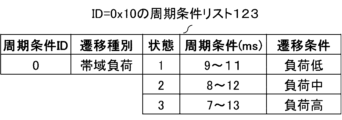
- FIG. 3 is a conceptual diagram showing a specific example of the format of a periodic condition list 123.
- FIG. 12 is a conceptual diagram showing a specific example of the format of a periodic condition list 124.
- FIG. 12 is a conceptual diagram showing a specific example of the format of a periodic condition list 125.
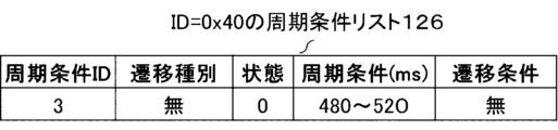
- FIG. 12 is a conceptual diagram showing a specific example of the format of a periodic condition list 126.
- FIG. 1 is a hardware configuration diagram showing a hardware configuration of an unauthorized communication detection device 100 according to Embodiment 1.
- FIG. 2 is a flowchart showing the operation of the fraudulent communication detection device 100 according to the first embodiment.
- 1 is a configuration diagram showing the configuration of a communication permission list generation device 200 according to Embodiment 1.
- FIG. FIG. 3 is a flow diagram for explaining the internal operation and input/output information of the processing unit 210 according to the first embodiment.
- 3 is a conceptual diagram showing a specific example of a format of communication specifications 221.
- FIG. 3 is a conceptual diagram showing a specific example of a format of communication data 222.
- FIG. 1 is a hardware configuration diagram showing a hardware configuration of an unauthorized communication detection device 100 according to Embodiment 1.
- FIG. 2 is a flowchart showing the operation of the fraudulent communication detection device 100 according to the first embodiment.
- 1 is
- FIG. 3 is a conceptual diagram showing a specific example of a format of a setting definition 223.
- FIG. 1 is a hardware configuration diagram showing a hardware configuration of a communication permission list generation device 200 according to Embodiment 1.
- FIG. 3 is a flowchart showing communication specification analysis processing performed by communication specification analysis section 211 according to the first embodiment.
- 3 is a flowchart showing a message information analysis subroutine performed by communication specification analysis section 211 according to the first embodiment.
- 3 is a flowchart showing a signal information analysis subroutine performed by communication specification analysis section 211 according to the first embodiment.
- 3 is a conceptual diagram showing a specific example of an internally generated file 301.
- FIG. 3 is a conceptual diagram showing a specific example of an internally generated file 302.
- FIG. 1 is a hardware configuration diagram showing a hardware configuration of a communication permission list generation device 200 according to Embodiment 1.
- FIG. 3 is a flowchart showing communication specification analysis processing performed by communication specification analysis section 211 according to the first embodiment
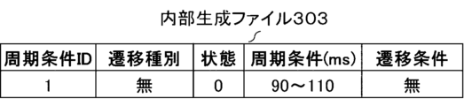
- FIG. 3 is a conceptual diagram showing a specific example of an internally generated file 303.
- FIG. 3 is a conceptual diagram showing a specific example of an internally generated file 304.
- FIG. 3 is a conceptual diagram showing a specific example of an internally generated file 305.
- FIG. 3 is a flowchart showing communication permission list output processing performed by communication permission list output unit 212 according to the first embodiment.
- 5 is a flowchart illustrating communication data analysis processing performed by the communication data analysis unit according to the first embodiment.
- Embodiment 1 an unauthorized communication detection phase in which unauthorized communication is detected based on a communication permission list will be described, and then a communication permission list generation phase will be described in which the communication permission list is generated. Further, a communication system is configured by combining the unauthorized communication detection device described in the unauthorized communication detection phase and the communication permission list generation device described in the communication permission list generation phase.
- FIG. 1 is a configuration diagram showing the configuration of a vehicle system 10 according to the first embodiment.
- the vehicle system 10 includes a GW (Gateway) 11, a cable 12, a first vehicle-mounted device 1, a second vehicle-mounted device 2, . . . an n-th vehicle-mounted device n.
- n is an integer greater than or equal to 1, and an actual vehicle is equipped with tens to hundreds of on-vehicle devices.
- the GW 11, the first in-vehicle device 1, the second in-vehicle device 2, . . . the n-th in-vehicle device n communicate with each other via the cable 12.
- the cable 12 is a cable compatible with CAN (Controller Area Network) communication, which is standardly used in in-vehicle communication. Since CAN is a broadcast communication, the GW 11 can receive all communication flowing through the cable 12.
- CAN Controller Area Network
- FIG. 2 is a configuration diagram showing the configurations of the GW 11 and the unauthorized communication detection device 100.
- the GW 11 includes an unauthorized communication detection device 100, a GW function section 130, and a communication section 140.
- section means an element of a functional configuration, and “section” may be read as “process” or "process” as appropriate.
- the operation of the unauthorized communication detection device 100 corresponds to an unauthorized communication detection method
- the program that causes a computer to execute the unauthorized communication detection method corresponds to an unauthorized communication detection program.
- the GW function unit 130 transfers communication messages.
- the communication unit 140 is for communicating data.
- the communication unit 140 includes a receiving unit 141 that receives data and a transmitting unit 142 that transmits data. Furthermore, the receiving unit 141 has a function of observing the bandwidth load status of the cable 12 by counting the number of communication messages received per unit time.
- the fraudulent communication detection device 100 detects fraud in communication messages flowing through the vehicle system 10, and includes a processing section 110 and a storage section 120.
- the processing unit 110 includes a communication acquisition unit 111, a communication determination unit 112, and an alert unit 113.
- the communication acquisition unit 111 acquires communication messages.
- the communication acquisition unit 111 acquires the communication message received by the reception unit 141 together with the reception time information at the reception unit 141, and transmits it to the communication determination unit 112.
- the communication determination unit 112 determines whether or not a communication message is a normal message based on a periodic condition set for each time-varying state of the communication message.
- the state of the communication message indicates the characteristics of the communication message that affect the periodic error
- the state of the communication message indicates the transition type and the factor that affects the periodic error of the communication message.
- a plurality of transition conditions set for each transition type that is, the communication determination unit 112 specifies the cycle condition of the communication message based on the state of the communication message that is classified based on the transition type and the transition condition, and determines whether the communication message is a normal message.
- transition state After dividing the characteristics that affect the periodic error of communication messages into multiple transition states such as bandwidth load, number of transmissions, and time interval, we further divide multiple items into each category. It is set as a transition condition. Details of the transition state and transition conditions will be described later.
- the communication determination unit 112 determines whether a communication message is a normal message by referring to a cycle condition list in which cycle conditions are set for each state of the communication message. More specifically, the communication determination unit 112 determines whether the communication message is a normal message by determining whether the reception cycle of the communication message deviates from a cycle range defined in a cycle condition list described later. Determine whether
- the communication determination unit 112 classifies communication messages based on the transition type, which is a factor that affects the periodic error of communication messages, and a plurality of transition conditions set for each transition type. Based on the state of , the periodic condition of the communication message is specified, and it is determined whether the communication message is a normal message.
- the transition type here is, for example, a bandwidth load, the number of transmissions, or a time interval, and in the first embodiment, the communication determination unit 112 uses the transition type based on at least one of the bandwidth load, the number of transmissions, or the time interval.
- the state of the communication message is specified, and it is determined whether the communication message is a normal message based on a periodic condition set for the specified state of the communication message.
- the alert unit 113 presents an alert to the user when the communication determination unit 112 determines that the communication message is not a normal message.
- the storage unit 120 stores various information, particularly the communication permission list 121.
- the communication permission list 121 defines rules for detecting unauthorized communication, and includes a rule list 122 and cycle condition lists 123 to 126. That is, in the first embodiment, the storage unit 120 stores the plurality of cycle condition lists 123 to 126 and the rule list 122 as the communication permission list 121.
- the rule list 122 associates an ID included in a communication message with a periodic condition ID indicating the type of periodic condition list.
- the cycle condition lists 123 to 126 have cycle conditions set for each communication message state. More specifically, the cycle condition list holds a normal cycle range for each state of a communication message as a cycle condition.
- the communication permission list 121 is stored in a non-volatile storage device, and expanded from the non-volatile storage device to the memory when the GW 11 starts up.
- the storage unit 120 stores data (not shown) that is used, generated, input, output, transmitted, or received by the GW 11.
- FIG. 3 shows a message format of a CAN communication message that flows within the vehicle system 10 and is detected by the unauthorized communication detection device 100.
- a CAN communication message includes an ID, a DLC, and a data field.
- the ID is a message number assigned to uniquely identify a communication message.
- DLC Data Length Code
- the data field is a field in which data used by an application is stored, and is a maximum of 8 bytes in CAN communication.
- a data field consists of multiple signals. Signals can have a data length of 1 to 64 bits.
- the ID, DLC, data field, and details of each signal are defined for each vehicle system 10.
- CAN communication messages include many periodic messages that are periodically transmitted at a predetermined period for each message.
- the cycle is not always maintained accurately, and errors such as early arrivals and delays occur due to the influence of various factors.
- some of these periodic messages exhibit characteristics in the transition of periodic errors. For example, in the case of a periodic message having a short period such as 10 ms, it is easily affected by the bandwidth load of the CAN cable, and when the load is high, the transmission delay tends to be long and the periodic error tends to be large. Alternatively, there are some that repeat behavior that causes large periodic errors at fixed timings, such as the number of transmissions or time intervals. It is presumed that these are caused by the influence of the in-vehicle device that transmits the periodic message or the application on the in-vehicle device. The present disclosure relates to a method of setting periodic conditions for periodic messages having these characteristics.
- FIG. 4 shows an example of the internal structure and possible values of the rule list 122 that constitutes the communication permission list 121.
- the communication permission list 121 is a list that describes information on normal CAN messages flowing within the vehicle system 10.
- Items that make up the rule list 122 in the communication permission list 121 include rule number, ID, DLC, signal condition, and periodic condition ID.
- the rule number is a number sequentially assigned to uniquely identify each rule within the rule list 122.
- the ID and DLC correspond to the ID and DLC in the CAN communication message shown in FIG. 3.
- the signal conditions define the leading bit, length, minimum value, and maximum value of each signal in the CAN communication message shown in FIG. 3.
- the periodic condition ID is a number for linking a periodic message to a periodic condition list that defines the periodic condition.
- the rule list 122 only four CAN message rules are shown in the rule list 122 for simplicity, but all information on normal CAN messages that can flow through the vehicle system 10, including messages that do not have periodicity, is shown in the rule list 122. It is desirable to fill in the information completely.
- Items forming the periodic condition list 123 include periodic condition ID, transition type, state, periodic condition, and transition condition.
- Ru As the transition type, one of "bandwidth load”, “counter”, “time”, and “none” is written.
- the "counter" corresponds to the number of transmissions
- time corresponds to the time interval.
- This item may be in a format in which a predetermined type number or the like is written instead of a character string.
- the periodic error changes to less than ⁇ 1 ms, less than ⁇ 2 ms, and less than ⁇ 3 ms in three stages of band load: low, medium, and high, so these three stages are defined as states.
- the periodic condition is described as a periodic condition that is considered normal in each state as a range of possible values for the time since the previous reception.
- the internal structure of the periodic condition list 124 is the same as that of the periodic condition list 123.
- the cycle condition ID is 1, and the transition type is "counter”. Two states are defined: "first three packets" and "last one packet.”
- the internal structure of the periodic condition list 125 is the same as that of the periodic condition list 123.
- the cycle condition ID is 2
- the transition type is "time”. Two states are defined: "first 39 seconds” and "later 1 second.”
- the internal structure of the periodic condition list 126 is the same as that of the periodic condition list 123.
- the cycle condition ID is 3, and the transition type is "none". Since the state is not defined, it is set to 0, and the transition condition is also set to "none".
- the cycle condition is a value in which an arbitrary margin is provided for a cycle of 500 ms in consideration of cycle errors that may occur in an actual vehicle environment. In the first embodiment, a margin of ⁇ 20 ms is provided.
- FIG. 9 is a hardware configuration diagram showing the hardware configuration of the unauthorized communication detection device 100.
- the communication acquisition unit 111, communication determination unit 112, and alert unit 113 included in the fraudulent communication detection device 100 are realized by the processing device 1001 executing a program stored in the storage device 1002.
- the processing device 1001 is a processor such as a CPU (Central Processing Unit), an arithmetic unit, a microprocessor, a microcomputer, or a DSP (Digital Signal Processor). Further, each function of the unauthorized communication detection device 100 may be realized by a plurality of processors. Furthermore, each function of the unauthorized communication detection device 100 may be implemented using an FPGA (Field Programmable Gate Array), an ASIC, or the like.
- the storage unit 120 is realized by a storage device 1002, and the storage device 1002 includes, for example, RAM (Random Access Memory), ROM (Read Only Memory), flash memory, EPROM (Erasable Programmable ROM), Non-volatile devices such as EPROM (Electrically EPROM) It may be a flexible or volatile semiconductor memory, a magnetic disk such as a hard disk or a flexible disk, or an optical disk such as a mini disk, a CD (Compact Disc), or a DVD (Digital Versatile Disc).
- RAM Random Access Memory
- ROM Read Only Memory
- flash memory e.g., NAND
- EPROM Erasable Programmable ROM
- Non-volatile devices such as EPROM (Electrically EPROM) It may be a flexible or volatile semiconductor memory, a magnetic disk such as a hard disk or a flexible disk, or an optical disk such as a mini disk, a CD (Compact Disc), or a DVD (Digital Versatile Disc).
- the communication device 3 is a device that performs communication, and includes a receiver and a transmitter. Specifically, the communication device 3 is a communication chip or NIC (Network Interface Card).
- NIC Network Interface Card
- FIG. 10 is a flowchart of fraudulent communication detection processing performed by the fraudulent communication detection device 100.
- step S1 the communication acquisition unit 111 acquires the communication message received by the reception unit 141 together with the reception time information at the reception unit 141, and transmits it to the communication determination unit 112.
- step S2 the communication determination unit 112 analyzes the contents of the passed communication message and obtains the values of the ID, DLC, and data fields included in the message.
- step S3 the communication determination unit 112 determines whether information matching the communication message exists in the rule list 122. In the determination, a search is made from among the detection rules listed in the rule list 122 for a rule whose ID condition and DLC condition match the values acquired in step S2. If a matching rule exists, the values are read from the data field according to the leading bit and length information for all signals listed in the signal conditions of that rule, and checked to see if they are within the range of possible values.
- step S3 If it is determined in step S3 that matching information does not exist in the rule list 122, the process proceeds to step S9, and the alert unit 113 performs predetermined alert processing.
- Alert processing includes transmitting log information indicating the occurrence of unauthorized communication to a log storage device (not shown) in the vehicle system 10 via the transmitter 242, and displaying a warning message on an operation panel (not shown).
- Various processes may be performed, such as notifying the occupant of the vehicle system 10 of the vehicle system 10. After executing the above processing steps, this flowchart ends.
- step S4 the communication determination unit 112 refers to the periodic condition ID of the rule list 122, and refers to the periodic condition ID of the corresponding periodic condition list (123 to 126). either).
- step S5 the communication determination unit 112 refers to the transition type in the acquired cycle condition list and identifies the current state regarding the message.
- the transition type in the cycle condition list 126 is "none", so no further processing is performed and the process moves to step S6.
- step S6 the communication determination unit 112 acquires the periodic condition corresponding to the specified state.
- step S7 the communication determination unit 112 compares the reception time information acquired in step S1 with the previous reception time information regarding the message that has been internally held in advance, and determines that the reception interval is based on the periodicity condition acquired in step S6. Check if it is within the range.
- step S7 If it is determined in step S7 that the cycle condition is outside the range, the process proceeds to step S9, and after the alert unit 113 performs a predetermined alert process, this flowchart ends.
- step S7 If it is determined in step S7 that the period is within the periodicity condition, the message is determined to be a normal message, and in step S8, the communication determination unit 112 updates the information of the message. Specifically, the communication determination unit 112 overwrites the previous reception time information regarding the message held internally with the reception time information passed in step S1. Further, if the message is of the transition type "counter", the communication determining unit 112 increments the value of the reception counter of the message that is managed internally. After executing the above processing steps, the unauthorized communication detection device 100 ends its operation.
- the unauthorized communication detection device 100 by determining a communication message based on the periodic condition for each state that changes over time, it is possible to more accurately determine whether a communication message is a normal message. Additionally, if a fraudulent message is sent from a fraudulent in-vehicle device installed inside a vehicle that deceives the controls related to the vehicle's driving, it will be possible to detect this and raise an alert. .
- periodic messages by defining the characteristics that affect the periodic error that can occur for each message as a state, and dynamically switching to the periodic condition corresponding to the current state, we can perform fine-grained fraudulent communication detection that responds to changes in the periodic error. It becomes possible to realize this.
- Communication permission list generation phase Next, the generation process of the communication permission list 121 will be explained.
- Manually creating the communication permission list 121 as described above requires a high workload, and there is a possibility that omissions or errors may occur. Therefore, there is a need for a communication permission list generation tool that automatically generates the communication permission list 121 shown in FIG. 2.
- the communication permission list generation device 200 that automatically generates the communication permission list 121 will be described below. Furthermore, the operation of the communication permission list generation device 200 corresponds to a communication permission list generation method, and the program that causes a computer to execute the communication permission list generation method corresponds to a communication permission list generation program.
- FIG. 11 is a configuration diagram showing the configuration of the communication permission list generation device 200.
- Communication permission list generation device 200 includes a processing section 210 and a storage section 220.
- the storage unit 220 stores various information, and stores communication specifications 221, communication data 222, setting definitions 223, communication permission list 224, and updated communication permission list 225.
- the communication specification 221 is a file that defines communication specifications for CAN messages flowing within the vehicle system 10 shown in FIG. Details of the communication specifications 221 will be described later with reference to FIG.
- the communication data 222 is a file in which CAN messages actually flowing within the vehicle system 10 shown in FIG. 1 are obtained and saved using a packet capture tool or the like.
- the setting definition 223 is a file that describes setting information when the processing unit 210 operates. Details of the setting definition 223 will be described later with reference to FIG.
- the communication permission list 224 is a file output by the communication permission list output unit 212
- the updated communication permission list 225 is a file output by the communication data analysis unit 213.
- the storage unit 220 stores data (not shown) that is used, generated, input, output, transmitted, or received by the communication permission list generation device 200.
- the processing unit 210 includes a communication specification analysis unit 211, a communication permission list output unit 212, and a communication data analysis unit 213.
- the communication specification analysis unit 211 analyzes communication specifications that define the specifications of normal communication messages.
- the communication permission list output unit 212 generates a communication permission list used to detect fraudulent communication messages based on the analysis results of the communication specification analysis unit.
- the communication data analysis unit 213 Based on the actual communication data 222, the communication data analysis unit 213 identifies conditions that cause fluctuations in the periodic error of communication messages included in the communication data 222, determines a normal periodic range for each specified condition, and determines whether communication is permitted. It updates the list. Moreover, the condition here means a transition type and a transition condition.
- the communication data analysis unit 213 calculates the bandwidth load for each unit time based on the communication data 222, classifies the calculated bandwidth load into multiple stages, and compares the periodic error for each of the multiple stages. Identify the conditions by More specifically, when the difference between the periodic errors of multiple stages is larger than a predetermined threshold, the communication data analysis unit 213 identifies that the transition type among the conditions is "bandwidth load" and applies the classified multiple Identify transition conditions based on stages. More detailed processing will be explained with reference to FIG. 25.
- the communication data analysis unit 213 identifies the cause by determining whether the periodic error of the communication message exceeds a predetermined threshold at a constant counter interval. More specifically, the communication data analysis unit 213 specifies that the transition type among the conditions is "number of transmissions" when the periodic error of the communication message exceeds a predetermined threshold at a certain counter interval, A transition condition is specified based on the above-mentioned constant counter interval. More detailed processing will be explained with reference to FIG. 25.
- the communication data analysis unit 213 identifies the condition by determining whether the periodic error of the communication message exceeds a predetermined threshold at a constant time interval. More specifically, the communication data analysis unit 213 identifies that the transition type of the condition is "time interval" when the periodic error of the communication message exceeds a predetermined threshold at a certain time interval, A transition condition is specified based on the above-mentioned fixed time interval. More detailed processing will be explained with reference to FIG. 25.
- FIG. 12 is a flow diagram regarding the internal operation and input/output information of the processing unit 210 shown in FIG. 11.
- the processing unit 210 inputs the communication specification 221, setting definition 223, and communication data 222, and outputs the updated communication permission list 225. Furthermore, inside the processing unit 210, a communication permission list 224 is generated.
- the communication specification analysis unit 211 analyzes the contents of the communication specification 221 based on the setting definition 223. The analysis result is output to the communication permission list output section 212.
- the communication permission list output unit 212 generates a communication permission list 1024 according to the contents of the input analysis result.
- the communication data analysis unit 213 analyzes the contents of the communication data 222, updates the contents of the communication permission list 224 according to the analysis result, and outputs the updated result as an updated communication permission list 1025.
- the processing unit 210 may output the communication permission list 224 to the outside rather than just internal information. In this case, the processing unit 210 will output both the communication permission list 224 and the updated communication permission list 225.
- the processing section 210 may be divided into a functional section consisting of a communication specification analysis section 211 and a communication permission list output section 212, and a functional section consisting of a communication data analysis section 213, and each of them may operate as a separate device.
- a functional unit consisting of the communication specification analysis unit 211 and the communication permission list output unit 212 receives the communication specification 221 and the setting definition 223 as input, and outputs the communication permission list 224.
- the functional unit consisting of the communication data analysis unit 213 inputs the communication specification 221, the communication data 222, and the communication permission list 224, and outputs an updated communication permission list 225.
- FIG. 13 is an example of the format of the communication specification 221 shown in FIGS. 11 and 12.
- the communication specification 221 is a CAN database file in which specifications of CAN messages flowing within the vehicle system 10 are defined.
- the communication specifications 221 are created and used at the development stage of each vehicle-mounted device such as the vehicle system 10, the GW (Gateway) 11, the first vehicle-mounted device 1, the second vehicle-mounted device 2, ... the nth vehicle-mounted device n, etc. This is design information.
- the communication specification 221 may not be one file, but may be a plurality of files.
- the communication specification 221 includes information such as device information, message information, information on signals forming the message, message type information, and message cycle information.
- the device information is the name of an in-vehicle device that is defined in the communication specification 221 and is involved in sending and receiving messages.
- the message information includes information regarding each message, such as the message ID, DLC, and the name of the sender's in-vehicle device. Each message information comprises signal information that constitutes the data field portion of the message.
- the signal information includes information such as the signal name, start bit, length, and possible values.
- the message type information is information regarding the type of each message defined in the message information. Message types include messages sent by event triggers and messages sent periodically.
- the message cycle information is information regarding the transmission cycle of a message defined as a message having a cycle in the message type information.
- FIG. 14 is an example of the format of the communication data 222 shown in FIGS. 11 and 12.
- the communication data 222 is a file in which communication messages flowing within the vehicle system 10 are acquired and saved using a packet capture tool or the like.
- the communication data 222 is acquired in an actual vehicle or in a simulator environment during the development stage of each in-vehicle device such as the vehicle system 10, GW (Gateway) 11, first in-vehicle device 1, second in-vehicle device 2, and n-th in-vehicle device n. This is information for development and evaluation.
- the communication data 222 may not be one file but multiple files.
- the communication data 222 includes date information and information regarding the captured communication message.
- Information regarding the message is the capture time, message ID, DLC, and data field.
- FIG. 15 is an example of the format of the setting definition 223 shown in FIGS. 11 and 12.
- the setting definition 223 is a text file that defines setting information related to the operation of the processing unit 210.
- the setting definition 223 includes information regarding the target device, cycle range, and the like.
- the target device defines the in-vehicle device that is the source of the message that is to be analyzed by the communication specification analysis unit 211.
- the communication permission list 224 output by the communication permission list output unit 212 defines only rules regarding messages transmitted by the in-vehicle device defined as the target device. It is also possible to omit the definition of the target device. In this case, all messages defined in the communication specification 221 are to be analyzed by the communication specification analysis unit 211.
- the cycle range is a ratio that specifies how much margin to define as the cycle condition of the communication permission list 224 with respect to the cycle information defined in the communication specifications 221. The ratio defined in the cycle range is applied to all cycle messages defined in the communication specification 221.
- FIG. 16 is a hardware configuration diagram showing the hardware configuration of the communication permission list generation device 200.
- the communication specification analysis unit 211, the communication permission list output unit 212, and the communication data analysis unit 213 included in the communication permission list generation device 200 are realized by the processing device 2001 executing a program stored in the storage device 2002. .
- the processing device 2001 is a processor such as a CPU (Central Processing Unit), an arithmetic unit, a microprocessor, a microcomputer, or a DSP (Digital Signal Processor). Further, each function of the unauthorized communication detection device 100 may be realized by a plurality of processors. Furthermore, each function of the communication permission list generation device 200 may be implemented using an FPGA (Field Programmable Gate Array), ASIC, or the like.
- the storage unit 220 is realized by a storage device 2002, and the storage device 2002 includes, for example, a RAM (Random Access Memory), a ROM (Read Only Memory), a flash memory, an EPROM (Erasable Programmable ROM), an E Non-volatile devices such as EPROM (Electrically EPROM) It may be a flexible or volatile semiconductor memory, a magnetic disk such as a hard disk or a flexible disk, or an optical disk such as a mini disk, a CD (Compact Disc), or a DVD (Digital Versatile Disc).
- FIG. 17 is a flowchart of communication specification analysis processing performed by the communication specification analysis unit 211 shown in FIGS. 11 and 12.
- step S201 the communication specification analysis unit 211 reads the contents of the communication specification 221 received as input. Specifically, message information is searched from the beginning of the format of the communication specification 221 shown in FIG. 13.
- step S202 the communication specification analysis unit 211 determines whether message information exists. If a message exists, a subroutine for message information analysis processing is executed in step S203. The message information analysis subroutine will be described later with reference to FIG. After executing the message information analysis subroutine, the process returns to step S202, and thereafter, the processing steps of steps S202 to S203 are repeated until all message information in the communication specification 221 is analyzed.
- step S202 if the communication specification analysis unit 211 determines that the next message information does not exist, this flowchart ends.
- FIG. 18 is a flowchart of the message information analysis subroutine performed by the communication specification analysis unit 211. The process in FIG. 18 corresponds to step S203 in FIG. 17.
- step S301 the communication specification analysis unit 211 acquires the name of the in-vehicle device that sent the message to be analyzed from the communication specification 221.
- step S302 it is determined whether the transmission source in-vehicle device name acquired in step S301 is defined as a target device in the setting definition 223 shown in FIG. If it is not defined, this flowchart ends immediately.
- the communication specification analysis unit 211 acquires the ID and DLC of the message to be analyzed from the communication specification 221 in step S303.
- step S304 the communication specification analysis unit 211 acquires the message type of the message to be analyzed from the communication specification 221.
- step S305 the communication specification analysis unit 211 determines whether the message to be analyzed is a periodic message.
- the communication specification analysis unit 211 acquires the periodicity information of the message to be analyzed from the communication specification 221, and sets the lower limit at the ratio specified in the periodic range of the setting definition 223 shown in FIG. Calculate the value and upper limit. For example, if the acquired period information is 10 ms and 10% is specified in the period range of the setting definition 1023, the period condition of the periodic message is in the range of 9 to 11 ms.
- step S307 a subroutine for signal information analysis processing is executed.
- the signal information analysis subroutine will be described later with reference to FIG.
- step S305 if it is determined in step S305 that the message is not a periodic message, the process immediately advances to step S307 and executes a signal information analysis subroutine. After executing the above processing steps, this flowchart ends.
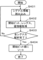
- FIG. 19 is a flowchart of the signal information analysis subroutine performed by the communication specification analysis unit 211.
- FIG. 19 corresponds to step S307 in FIG.
- step S401 the communication specification analysis unit 211 reads signal information of the message to be analyzed from the communication specification 221.
- step S402 the communication specification analysis unit 211 obtains information on the start bit, length, and possible values from the signal information.
- step S403 the communication specification analysis unit 211 determines whether all signal information related to the message to be analyzed has been analyzed.
- step S404 If it has not been completed, the process returns to step S404, and thereafter, the processing steps of steps S401 to S403 are repeated until there is no unanalyzed signal information.
- step S403 When the analysis of all the signal information related to the message to be analyzed is completed in step S403, the communication specification analysis unit 211, in step S404, sorts the information of each signal acquired in step S402 in ascending order of the start bit.
- FIGS. 20 to 24 are examples of files generated as a result of the communication specification analysis processing by the communication specification analysis unit 211 shown in FIGS. 17 to 19.
- Each file shown in FIGS. 20 to 24 is information that is input from the communication specification analysis section 211 to the communication permission list output section 212 within the processing section 210.
- the internally generated file 301 shown in FIG. 20 includes an ID, DLC, signal condition, and cycle condition ID.
- the information acquired in S303 of FIG. 18 is stored as the ID and DLC.
- the signal condition includes a start bit, length, minimum value, and maximum value, and the information acquired in S402 of FIG. 19 is stored in each of them.
- the signal conditions for each ID are recorded in the internally generated file 301 in ascending order of the value of the start bit.
- the periodic condition ID is a number for linking the periodic message to any of internally generated files 302 to 305, which will be described later.
- information of four periodic messages with IDs 0x10, 0x20, 0x30, and 0x40, which are the same as those illustrated in FIG. 4, are described.
- the internally generated file 302 shown in FIG. 21 is a file in which periodic conditions regarding the message with ID 0x10 are stored.
- the periodicity range calculated in S306 of FIG. 18 is stored in the periodicity condition. Since information regarding the transition type, state, and transition condition cannot be obtained from the communication specification 221, "None" is stored as the transition type, 0 is the state, and "None" is stored as the transition condition.
- the internally generated file 303 shown in FIG. 22 is a file in which periodic conditions regarding the message with ID 0x20 are stored.
- the internally generated file 304 shown in FIG. 23 is a file in which cycle conditions regarding the message with ID 0x30 are stored.
- the internally generated file 305 shown in FIG. 24 is a file in which cycle conditions regarding the message with ID 0x40 are stored.
- the period range calculated in S306 of FIG. 18 is stored in the period condition, the transition type is "none", the state is 0, and the transition condition is "none". is stored.
- FIG. 25 is a flowchart of communication permission list output processing performed by the communication permission list output unit 212 shown in FIGS. 11 and 12.
- step S501 the communication permission list output unit 212 determines whether the communication permission list 224 already exists.
- the communication permission list output unit 212 creates a new communication permission list 224 in step S502.
- the communication permission list 224 like the communication permission list 121 shown in FIG. 2, is composed of a rule list and a plurality of cycle condition lists. After executing the processing step of step S502, the process advances to step S504.
- step S503 the communication permission list output unit 212 opens a file so that the existing communication permission list 224 can be edited, and then proceeds to step S504.
- step S504 the communication permission list output unit 212 determines whether message information exists in the internally generated file 301.
- the communication permission list output unit 212 determines whether the rule corresponding to the message information in the internally generated file 301 already exists in the communication permission list 224. Specifically, the ID of the target message is obtained from the internally generated file 301, and it is first determined whether a rule with the same ID exists in the rule list in the communication permission list 224. If it exists, it is determined whether the DLC, signal condition, and periodic condition ID of the internally generated file 301 match the DLC, signal condition, and periodic condition ID of the rule in the corresponding communication permission list 224.
- the file with the corresponding cycle condition ID is further identified among the internally generated files 302 to 305, the cycle condition is acquired from that file, and the corresponding cycle in the communication permission list 224 is specified. Determine whether it matches the cycle condition in the condition list. If they match, it is determined that a rule with the same ID exists in the communication permission list 224, and the process returns to step S504.
- the communication permission list output unit 212 outputs information on the ID, DLC, signal condition, and cycle condition ID of the internally generated file 301 in step S506. , information on the transition condition, state, periodic condition, and transition condition of the file with the corresponding periodic condition ID among the internally generated files 302 to 305 is added to the communication permission list 224, and the process returns to step S504.
- step S504 to step S506 are repeated until all message information in the internally generated file 301 is read.
- step S504 if the next message information no longer exists in the internally generated file 301, this flowchart ends.
- the rule list in the communication permission list 224 that is generated when the communication permission list output process shown in FIG. 25 is executed using the contents of the internally generated files 301 to 305 shown in FIGS.
- the format of the periodic condition list is the same as the rule list 122 and periodic condition list 123 to periodic condition list 126 shown in FIGS. 4 to 8.
- FIG. 26 is a flowchart of communication data analysis processing performed by the communication data analysis unit 213 shown in FIGS. 11 and 12.
- step S601 the communication data analysis unit 213 reads the contents of the communication data 222 received as input.
- step S602 the communication data analysis unit 213 calculates the bandwidth load for each unit time from the content of the communication data 222, and analyzes the communication log for each unit time with low (less than 40%), medium (40% or more) bandwidth load. It is classified into three levels: less than 70%) and high (more than 70%).
- step S603 the communication data analysis unit 213 refers to the rule list in the communication permission list 224 generated in the communication permission list output process shown in FIG. determine whether it exists. If the analysis of all periodic messages has been completed, this flowchart ends.
- step S603 If it is determined in step S603 that there is an unanalyzed periodic message, the communication data analysis unit 213 acquires all communication logs that match the ID of the periodic message from the communication data 222 in step S604, and each communication log Assign sequential log numbers from the beginning.
- step S605 the communication data analysis unit 213 determines, based on the classification result in step S602 and the acquisition result in step S604, the maximum value and minimum value of the periodic error of the periodic message in each period of low, medium, and high bandwidth load. get.
- step S606 the communication data analysis unit 213 compares the maximum value/minimum value of the periodic error for each band load and determines whether a difference greater than a predetermined threshold value has occurred.
- step S607 the communication data analysis unit 213 updates the contents of the periodic condition list regarding the periodic message in the communication permission list 224.
- Change the "transition type" in the periodic condition list to "bandwidth load”, define three stages of low, medium, and high bandwidth load in the state and transition conditions, and define the periodic conditions of each state as obtained in step S605.
- the contents of list 123 are updated.
- the communication data analysis unit 213 determines the periodic error from all communication logs of the periodic message acquired in step S604 in step S608. Extract logs that exceed a predetermined threshold.
- step S609 the communication data analysis unit 213 checks the log number of the extracted log, and checks whether communication logs with large discrepancies occur at a certain counter interval.
- step S610 the communication data analysis unit 213 classifies all communication logs of the periodic message acquired in step S604 into two groups: communication logs with large periodic errors and other communication logs. Then, obtain the maximum and minimum values of the periodic error in each group.
- step S611 the communication data analysis unit 213 updates the contents of the periodic condition list regarding the periodic message in the communication permission list 224.
- the transition conditions define the timing at which the periodic error becomes large and the other timings.
- a value range is set based on the maximum value and minimum value of the cycle error acquired in S2410.
- the contents of the list 124 are updated.
- step S609 determines that the log numbers of the communication logs with a large periodic error are not at a constant counter interval.
- the communication data analysis unit 213 determines in step S612 that the communication logs with a large periodic error are Divide into groups based on similar values and determine whether the time intervals between groups are constant.
- step S613 the communication data analysis unit 213 divides all communication logs of the periodic message acquired in step S604 into two groups: communication logs with a large periodic error and other communication logs. Classify and obtain the maximum and minimum periodic errors in each group.
- step S614 the communication data analysis unit 213 updates the contents of the periodic condition list regarding the periodic message in the communication permission list 224.
- the transition conditions define the timing at which the periodic error becomes large and the other timings.
- a value range is set based on the maximum value and minimum value of the cycle error acquired in S2413.
- the contents of list 125 are updated.
- step S615 the communication data analysis unit 213 calculates the maximum and minimum values of the periodic error in all communication logs of the periodic message acquired in step S604. get.
- step S616 the communication data analysis unit 213 updates the contents of the periodic condition list regarding the periodic message in the communication permission list 224.
- a value range based on the maximum value and minimum value of the period error acquired in step S615 is set as the period condition. Since the transition type, state, and transition condition have already been stored with the information "none", 0, and "none", respectively, in the process step S506 shown in step FIG. 25, they are not changed in this process step.
- the contents of list 126 are updated.
- step S603 After performing the above processing steps, the process returns to step S603, and thereafter, the processing steps from step S603 to step S616 are repeated until the analysis of all periodic messages is completed.
- the communication The data analysis unit 213 ends its operation.
- the communication permission list generation device 200 it is possible to automatically generate periodic conditions that take into account the characteristics of each periodic message from communication specifications and communication data without relying on manual labor. By using it in combination with the fraudulent communication detection device 100, it is possible to realize fraudulent communication detection that suppresses both false detections and detection omissions.
- the first embodiment targets CAN messages in a vehicle system as an example
- the application target of the unauthorized communication detection device and communication permission list generation device according to the present disclosure is not necessarily limited to the above.
- the unauthorized communication detection device according to the present disclosure may be installed in a device on an IoT system built in a factory, building, home, etc., and may detect TCP/IP communication via a wired LAN or wireless LAN. In this case, the items that make up the rule list 122 shown in FIG.
- the communication specification 1021 shown in FIG. 13 is a specification that defines TCP/IP communication flowing on the IoT system, and the communication data 222 shown in FIG. 13 is a file that captures the TCP/IP communication flowing on the IoT system. .
- the periodic condition lists 123 to 126 shown in FIGS. 5 to 8 can take: "bandwidth load,” “counter,” “time,” and “none.”
- other types may be provided.
- the transition type is not fixedly defined in advance, but is dynamically defined based on the feature amount of each periodic message extracted from the communication data 222 in the communication data analysis unit 213 shown in FIG. Also good.
- the unauthorized communication detection device and communication permission list generation device are suitable for use in detecting unauthorized communication of communication messages on a vehicle system or an IoT system.
Landscapes
- Engineering & Computer Science (AREA)
- Computer Security & Cryptography (AREA)
- Computer Networks & Wireless Communication (AREA)
- Signal Processing (AREA)
- Software Systems (AREA)
- Theoretical Computer Science (AREA)
- Computer Hardware Design (AREA)
- Physics & Mathematics (AREA)
- General Engineering & Computer Science (AREA)
- General Physics & Mathematics (AREA)
- Small-Scale Networks (AREA)
Priority Applications (5)
| Application Number | Priority Date | Filing Date | Title |
|---|---|---|---|
| DE112022006329.7T DE112022006329T5 (de) | 2022-03-11 | 2022-03-11 | Schadkommunikation-erkennungseinrichtung, kommunikationszulassungsliste-generierungseinrichtung, schadkommunikation-erkennungsverfahren, kommunikationszulassungsliste-generierungsverfahren, schadkommunikation-erkennungsprogramm und kommunikationszulassungsliste-generierungsprogramm |
| CN202280093166.5A CN118829984A (zh) | 2022-03-11 | 2022-03-11 | 非法通信检测装置、通信许可列表生成装置、非法通信检测方法、通信许可列表生成方法、非法通信检测程序和通信许可列表生成程序 |
| PCT/JP2022/010920 WO2023170928A1 (ja) | 2022-03-11 | 2022-03-11 | 不正通信検知装置、通信許可リスト生成装置、不正通信検知方法、通信許可リスト生成方法、不正通信検知プログラム、及び通信許可リスト生成プログラム |
| JP2023568237A JP7435929B2 (ja) | 2022-03-11 | 2022-03-11 | 不正通信検知装置、通信許可リスト生成装置、不正通信検知方法、通信許可リスト生成方法、不正通信検知プログラム、及び通信許可リスト生成プログラム |
| US18/778,512 US20240373227A1 (en) | 2022-03-11 | 2024-07-19 | Malicious communication detection device, communication permission list generation device, malicious communication detection method, communication permission list generation method, storage medium storing malicious communication detection program, and storage medium storing communication permission list generation program |
Applications Claiming Priority (1)
| Application Number | Priority Date | Filing Date | Title |
|---|---|---|---|
| PCT/JP2022/010920 WO2023170928A1 (ja) | 2022-03-11 | 2022-03-11 | 不正通信検知装置、通信許可リスト生成装置、不正通信検知方法、通信許可リスト生成方法、不正通信検知プログラム、及び通信許可リスト生成プログラム |
Related Child Applications (1)
| Application Number | Title | Priority Date | Filing Date |
|---|---|---|---|
| US18/778,512 Continuation US20240373227A1 (en) | 2022-03-11 | 2024-07-19 | Malicious communication detection device, communication permission list generation device, malicious communication detection method, communication permission list generation method, storage medium storing malicious communication detection program, and storage medium storing communication permission list generation program |
Publications (1)
| Publication Number | Publication Date |
|---|---|
| WO2023170928A1 true WO2023170928A1 (ja) | 2023-09-14 |
Family
ID=87936429
Family Applications (1)
| Application Number | Title | Priority Date | Filing Date |
|---|---|---|---|
| PCT/JP2022/010920 Ceased WO2023170928A1 (ja) | 2022-03-11 | 2022-03-11 | 不正通信検知装置、通信許可リスト生成装置、不正通信検知方法、通信許可リスト生成方法、不正通信検知プログラム、及び通信許可リスト生成プログラム |
Country Status (5)
| Country | Link |
|---|---|
| US (1) | US20240373227A1 (https=) |
| JP (1) | JP7435929B2 (https=) |
| CN (1) | CN118829984A (https=) |
| DE (1) | DE112022006329T5 (https=) |
| WO (1) | WO2023170928A1 (https=) |
Cited By (1)
| Publication number | Priority date | Publication date | Assignee | Title |
|---|---|---|---|---|
| JP2025059053A (ja) * | 2023-09-27 | 2025-04-09 | ソフトバンクグループ株式会社 | システム |
Citations (3)
| Publication number | Priority date | Publication date | Assignee | Title |
|---|---|---|---|---|
| WO2019087858A1 (ja) * | 2017-10-30 | 2019-05-09 | 日本電信電話株式会社 | 攻撃通信検出装置、攻撃通信検出方法、プログラム |
| JP2021005821A (ja) * | 2019-06-27 | 2021-01-14 | 矢崎総業株式会社 | 異常検出装置 |
| WO2022014027A1 (ja) * | 2020-07-17 | 2022-01-20 | 三菱電機株式会社 | 通信許可リスト生成装置、通信許可リスト生成方法、及び、プログラム |
Family Cites Families (1)
| Publication number | Priority date | Publication date | Assignee | Title |
|---|---|---|---|---|
| JP7215378B2 (ja) | 2019-09-18 | 2023-01-31 | トヨタ自動車株式会社 | 車載制御装置、情報処理装置、車両用ネットワークシステム、アプリケーションプログラムの提供方法、及びプログラム |
-
2022
- 2022-03-11 JP JP2023568237A patent/JP7435929B2/ja active Active
- 2022-03-11 DE DE112022006329.7T patent/DE112022006329T5/de active Pending
- 2022-03-11 CN CN202280093166.5A patent/CN118829984A/zh active Pending
- 2022-03-11 WO PCT/JP2022/010920 patent/WO2023170928A1/ja not_active Ceased
-
2024
- 2024-07-19 US US18/778,512 patent/US20240373227A1/en active Pending
Patent Citations (3)
| Publication number | Priority date | Publication date | Assignee | Title |
|---|---|---|---|---|
| WO2019087858A1 (ja) * | 2017-10-30 | 2019-05-09 | 日本電信電話株式会社 | 攻撃通信検出装置、攻撃通信検出方法、プログラム |
| JP2021005821A (ja) * | 2019-06-27 | 2021-01-14 | 矢崎総業株式会社 | 異常検出装置 |
| WO2022014027A1 (ja) * | 2020-07-17 | 2022-01-20 | 三菱電機株式会社 | 通信許可リスト生成装置、通信許可リスト生成方法、及び、プログラム |
Non-Patent Citations (1)
| Title |
|---|
| OSUGA, SETSUO.: "Database and knowledge base; 1st edition", 30 July 1989, OHMSHA LTD., ISBN: 4-274-07520-6, article OSUGA, SETSUO: "Passage; Database and knowledge base", pages: 91 - 96, XP009549456 * |
Cited By (1)
| Publication number | Priority date | Publication date | Assignee | Title |
|---|---|---|---|---|
| JP2025059053A (ja) * | 2023-09-27 | 2025-04-09 | ソフトバンクグループ株式会社 | システム |
Also Published As
| Publication number | Publication date |
|---|---|
| JPWO2023170928A1 (https=) | 2023-09-14 |
| JP7435929B2 (ja) | 2024-02-21 |
| CN118829984A (zh) | 2024-10-22 |
| US20240373227A1 (en) | 2024-11-07 |
| DE112022006329T5 (de) | 2024-10-31 |
Similar Documents
| Publication | Publication Date | Title |
|---|---|---|
| US11296965B2 (en) | Abnormality detection in an on-board network system | |
| KR102601578B1 (ko) | 사이버 공격에 대한 네트워크 보호 방법 | |
| EP3598329B1 (en) | Information processing method, information processing system, and program | |
| US20170126703A1 (en) | Vehicle communication apparatus, in-vehicle network system, and vehicle communication method | |
| EP3402128A1 (en) | Abnormality detection method, abnormality detection device, and abnormality detection system | |
| EP3852313A1 (en) | Network communication system, fraud detection electronic control unit and anti-fraud handling method | |
| EP3361677A1 (en) | Communication device, communication method and communication program | |
| JP2018026791A (ja) | フレーム伝送阻止装置、フレーム伝送阻止方法及び車載ネットワークシステム | |
| JP7435929B2 (ja) | 不正通信検知装置、通信許可リスト生成装置、不正通信検知方法、通信許可リスト生成方法、不正通信検知プログラム、及び通信許可リスト生成プログラム | |
| CN114731301B (zh) | 决定方法、决定系统以及程序记录介质 | |
| CN115065623A (zh) | 一种主被动相结合的私有工控协议逆向分析方法 | |
| US10296746B2 (en) | Information processing device, filtering system, and filtering method | |
| CN107070941A (zh) | 异常流量检测的方法和装置 | |
| JP7170945B2 (ja) | 通信許可リスト生成装置、通信許可リスト生成方法、及び、プログラム | |
| WO2019207764A1 (ja) | 抽出装置、抽出方法および記録媒体、並びに、検知装置 | |
| Francia III et al. | Applied machine learning to vehicle security | |
| US10666671B2 (en) | Data security inspection mechanism for serial networks | |
| CN116527389B (zh) | 端口扫描检测 | |
| CN108197498A (zh) | 获取数据的方法及装置 | |
| CN110535844B (zh) | 一种恶意软件通讯活动检测方法、系统及存储介质 | |
| CN113647064A (zh) | 信息处理装置 | |
| EP3605966B1 (en) | Intrusion detection device, intrusion detection method, and intrusion detection system | |
| CN112448943B (zh) | 用于在信号指纹系统中对网络模型进行分析和适配的方法 | |
| CA3186107A1 (en) | Method, apparatus, system, device, and storage medium for implementing terminal verification | |
| CN101548269B (zh) | 用于网络侦查流识别的方法、计算机程序产品和设备 |
Legal Events
| Date | Code | Title | Description |
|---|---|---|---|
| 121 | Ep: the epo has been informed by wipo that ep was designated in this application |
Ref document number: 22930909 Country of ref document: EP Kind code of ref document: A1 |
|
| WWE | Wipo information: entry into national phase |
Ref document number: 2023568237 Country of ref document: JP |
|
| WWE | Wipo information: entry into national phase |
Ref document number: 112022006329 Country of ref document: DE |
|
| WWE | Wipo information: entry into national phase |
Ref document number: 202280093166.5 Country of ref document: CN |
|
| 122 | Ep: pct application non-entry in european phase |
Ref document number: 22930909 Country of ref document: EP Kind code of ref document: A1 |