WO2023163100A1 - Electrolytic cell and electrolytic device - Google Patents
Electrolytic cell and electrolytic device Download PDFInfo
- Publication number
- WO2023163100A1 WO2023163100A1 PCT/JP2023/006710 JP2023006710W WO2023163100A1 WO 2023163100 A1 WO2023163100 A1 WO 2023163100A1 JP 2023006710 W JP2023006710 W JP 2023006710W WO 2023163100 A1 WO2023163100 A1 WO 2023163100A1
- Authority
- WO
- WIPO (PCT)
- Prior art keywords
- exchange membrane
- separator
- ion exchange
- electrolytic cell
- electrolytic
- Prior art date
Links
Images


Classifications
-
- C—CHEMISTRY; METALLURGY
- C25—ELECTROLYTIC OR ELECTROPHORETIC PROCESSES; APPARATUS THEREFOR
- C25B—ELECTROLYTIC OR ELECTROPHORETIC PROCESSES FOR THE PRODUCTION OF COMPOUNDS OR NON-METALS; APPARATUS THEREFOR
- C25B9/00—Cells or assemblies of cells; Constructional parts of cells; Assemblies of constructional parts, e.g. electrode-diaphragm assemblies; Process-related cell features
- C25B9/60—Constructional parts of cells
-
- C—CHEMISTRY; METALLURGY
- C25—ELECTROLYTIC OR ELECTROPHORETIC PROCESSES; APPARATUS THEREFOR
- C25B—ELECTROLYTIC OR ELECTROPHORETIC PROCESSES FOR THE PRODUCTION OF COMPOUNDS OR NON-METALS; APPARATUS THEREFOR
- C25B9/00—Cells or assemblies of cells; Constructional parts of cells; Assemblies of constructional parts, e.g. electrode-diaphragm assemblies; Process-related cell features
- C25B9/70—Assemblies comprising two or more cells
- C25B9/73—Assemblies comprising two or more cells of the filter-press type
- C25B9/77—Assemblies comprising two or more cells of the filter-press type having diaphragms
Definitions
- the present disclosure relates to electrolysis cells and electrolysis devices.
- This application claims priority to Japanese Patent Application No. 2022-26586 filed on February 24, 2022, the contents of which are incorporated herein.
- Patent Document 1 a hydrogen gas electrode is installed in the anode chamber, the hydrogen gas electrode is brought into close contact with the opposite side of the ion exchange membrane, and a mixed gas containing hydrogen and moisture is supplied to the hydrogen gas electrode.
- An electrolytic separation method is disclosed in which the salt is electrolyzed while This electrolytic separation method is intended to prevent the central region of the ion exchange membrane from drying out.
- Patent Document 2 a solid polymer electrolyte membrane provided between a pair of separators and having an anode and a cathode formed on both sides, and a power feeder interposed between the solid polymer electrolyte membrane and the separator
- a water electrolysis cell is disclosed in which an electrode formation surface is formed except for a portion where a gas pool occurs. This electrolysis cell aims to improve the efficiency of water electrolysis by eliminating gas retention at the end of the feeder.
- Patent Document 3 discloses a process of opening an on-off valve to release the pressure on the cathode side through a depressurization line; , and a step of performing water electrolysis treatment at normal pressure.
- This shutdown method aims to prevent the solid polymer electrolyte membrane from drying out by securing a good amount of water on the cathode side through the process at the time of shutdown.
- Patent Document 4 discloses an electrolytic device in which a separator is provided with a seal member that encircles a hydrogen discharge passage and a water passage section that encircles the seal member and allows water to flow. This electrolytic device prevents the outer portion of the sealing member from drying out in the vicinity of the hydrogen discharge passage.
- Japanese Patent No. 3201854 Japanese Patent No. 4611345 JP 2013-32572 A Japanese Patent No. 5364056
- the sealing portion protrudes outward from the sealing portion.
- the outer edge of the ion-exchange membrane which is exposed to water, tends to dry out. Then, when the outer edge of the ion-exchange membrane dries, there is a problem that the ion-exchange membrane is likely to deteriorate.
- the present disclosure has been made to solve the above problems, and aims to provide an electrolytic cell and an electrolytic device capable of suppressing deterioration of ion exchange membranes.
- the electrolytic cell includes a first separator, a second separator arranged with a space between the first separator, the first separator and the second separator and an ion exchange membrane that divides at least part of the space into a cathode chamber and an anode chamber; a sealing portion located outside the portion and sealing the space.
- An electrolytic device includes an electrolytic cell, an electrolytic solution supply section that supplies an electrolytic solution to the electrolytic cell, and a power supply section that applies voltage to the electrolytic cell.
- the electrolysis cell includes a first separator, a second separator that is arranged with a space between the first separator, and a separator that is arranged between the first separator and the second separator, and at least An ion-exchange membrane partially partitioned into an anode chamber and a cathode chamber, and an ion-exchange membrane disposed between the first separator and the second separator, positioned outside the outer edge of the ion-exchange membrane, and dividing the space. and a sealing portion for sealing.
- the electrolytic cell and electrolytic device of the present disclosure deterioration of the ion exchange membrane can be suppressed.
- FIG. 1 is a schematic configuration diagram showing the overall configuration of an electrolytic device according to a first embodiment of the present disclosure
- FIG. 1 is a cross-sectional view schematically showing an electrolytic cell of a first embodiment of the present disclosure
- FIG. 1 is an exploded perspective view showing an electrolytic cell of a first embodiment of the present disclosure
- FIG. 1 is a cross-sectional view showing an electrolytic cell of a first embodiment of the present disclosure
- FIG. FIG. 5 is a cross-sectional view of the electrolytic cell shown in FIG. 4 taken along line F5-F5
- FIG. 5 is a cross-sectional view along line F6-F6 of the electrolytic cell shown in FIG. 4;
- FIG. 4 is a cross-sectional view showing an electrolytic cell of a first modified example of the first embodiment of the present disclosure
- FIG. 4 is a cross-sectional view showing an electrolytic cell of a second modified example of the first embodiment of the present disclosure
- FIG. 5 is a cross-sectional view showing an electrolytic cell of a third modified example of the first embodiment of the present disclosure
- FIG. 11 is a cross-sectional view showing an electrolytic cell of a fourth modified example of the first embodiment of the present disclosure
- FIG. 4 is a cross-sectional view showing an electrolytic cell of a second embodiment of the present disclosure
- FIG. 12 is a cross-sectional view along line F12-F12 of the electrolytic cell shown in FIG. 11;
- FIG. 4 is a cross-sectional view showing an electrolytic cell of a third embodiment of the present disclosure
- FIG. 14 is a cross-sectional view of the electrolytic cell shown in FIG. 13 taken along line F14-F14
- FIG. 11 is a cross-sectional view showing an electrolytic cell of a modification of the third embodiment of the present disclosure
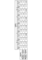
- 4 is a table showing the results of an evaluation test in which a specimen prepared as Example 1 of the first embodiment was held in a state simulating before and after exposure to the operating environment of an electrolytic device.
- 1 is a table showing the results of an evaluation test in which a specimen prepared as Comparative Example 1 for the evaluation of Example 1 was held in a state simulating before and after exposure to the operating environment of an electrolytic device.
- FIG. 4 is a table showing the results of an evaluation test in which a specimen prepared as Comparative Example 2 for the evaluation of Example 1 was held in a state simulating before and after exposure to the operating environment of an electrolytic device.
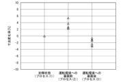
- 2 is a scatter diagram plotting the dimensional change rates obtained by an evaluation test performed on the specimen of Example 1 separately before and after exposure to the operating environment.
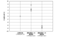
- 2 is a scatter diagram plotting the dimensional change rates obtained by an evaluation test performed on the specimen of Comparative Example 1 separately before and after exposure to the operating environment.
- FIG. 10 is a scatter diagram plotting the dimensional change rate obtained by the evaluation test performed on the specimen of Comparative Example 2 separately before and after exposure to the operating environment.
- the Z direction is a direction from a first separator 41 to a second separator 42, which will be described later.
- the X direction is a direction crossing (for example, perpendicular to) the Z direction, and is a direction from the center of the ion exchange membrane 43 to one end of the ion exchange membrane 43, which will be described later.
- the Y direction is a direction that intersects (for example, is orthogonal to) the Z direction and the X direction, and is, for example, the depth direction of the paper surface in FIG.
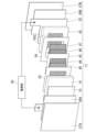
- FIG. 1 is a schematic configuration diagram showing the overall configuration of an electrolytic device 1 according to the first embodiment.
- the electrolytic device 1 is a device that generates hydrogen by electrolyzing water contained in an electrolytic solution.
- the electrolytic device 1 is, for example, an anion exchange membrane (AEM) type electrolytic device.
- AEM anion exchange membrane
- the electrolytic device 1 is not limited to the above example, and may be a different type of electrolytic device such as a device for electrolytically reducing carbon dioxide.
- the electrolytic device 1 includes, for example, an electrolytic cell stack 10, an electrolytic solution supply section 20, and a power supply section 30.
- the electrolysis cell stack 10 is an assembly of a plurality of electrolysis cells 11 .
- the electrolysis cell stack 10 is formed by arranging a plurality of electrolysis cells 11 in one direction.
- Each electrolytic cell 11 includes an anode chamber Sa and a cathode chamber Sb. The electrolytic cell 11 will be described later in detail.
- the electrolytic solution supply unit 20 is a supply unit that supplies the electrolytic solution to each electrolytic cell 11 .
- the electrolytic solution is, for example, an alkaline aqueous solution.
- the electrolytic solution supply section 20 includes an anode side supply section 20a and a cathode side supply section 20b.
- the anode-side supply part 20a is a supply part that supplies an electrolytic solution to the anode chamber Sa of each electrolytic cell 11.
- the anode-side supply section 20a includes, for example, a first electrolyte tank 21, a first pump 22, an oxygen recovery section 23, a first electrolyte supply section 24, and piping lines L1 and L2.
- the first electrolytic solution tank 21 stores the electrolytic solution.
- a supply port of the first electrolytic solution tank 21 is connected to the anode chamber Sa of the electrolytic cell 11 via a piping line L1.
- the first pump 22 is provided in the middle of the pipeline L ⁇ b>1 and sends the electrolyte stored in the first electrolyte tank 21 toward the anode chamber Sa of the electrolytic cell 11 .
- a return port of the first electrolytic solution tank 21 is connected to the anode chamber Sa of the electrolytic cell 11 via a piping line L2.
- the oxygen-containing electrolyte generated in the electrolytic cell 11 flows from the electrolytic cell 11 into the first electrolytic solution tank 21 .
- the first electrolytic solution tank 21 has a gas-liquid separator that separates oxygen contained in the electrolytic solution.
- the oxygen separated from the electrolyte by the first electrolyte tank 21 is recovered by the oxygen recovery unit 23 .
- the first electrolytic solution tank 21 is replenished with the electrolytic solution from the first electrolytic solution supply section 24 .
- the cathode-side supply section 20b is a supply section that supplies the electrolytic solution to the cathode chamber Sb of each electrolytic cell 11 .
- the cathode-side supply section 20b includes, for example, a second electrolyte tank 26, a second pump 27, a hydrogen recovery section 28, a second electrolyte supply section 29, and piping lines L3 and L4.
- the second electrolytic solution tank 26 stores the electrolytic solution.
- a supply port of the second electrolytic solution tank 26 is connected to the cathode chamber Sb of the electrolytic cell 11 via a piping line L3.
- the second pump 27 is provided in the middle of the pipeline L3 and sends the electrolyte stored in the second electrolyte tank 26 toward the cathode chamber Sb of the electrolytic cell 11 .
- the return port of the second electrolytic solution tank 26 is connected to the cathode chamber Sb of the electrolytic cell 11 via the piping line L4.
- the electrolytic solution containing hydrogen generated in the electrolytic cell 11 flows into the second electrolytic solution tank 26 from the electrolytic cell 11 .
- the second electrolytic solution tank 26 has a gas-liquid separator that separates hydrogen contained in the electrolytic solution.
- the hydrogen separated from the electrolyte by the second electrolyte tank 26 is recovered by the hydrogen recovering section 28 .
- the second electrolytic solution tank 26 is replenished with the electrolytic solution from the second electrolytic solution supply section 29 .
- the power supply unit 30 is a DC power supply that applies voltage to the electrolytic cell 11 .
- the power supply unit 30 applies a DC voltage necessary for electrolyzing the electrolytic solution between the anode and cathode of the electrolytic cell 11 .
- FIG. 2 is a cross-sectional view schematically showing the electrolytic cell 11.
- the electrolytic cell 11 includes, for example, a first separator 41 , a second separator 42 , an ion exchange membrane 43 , a first catalyst layer 44 , a first power feeder 45 , a second catalyst layer 46 and a second power feeder 47 .
- the first separator 41 is a member that defines one surface of the internal space S of the electrolytic cell 11 .
- the internal space S is a space including an anode chamber Sa and a cathode chamber Sb, which will be described later.
- the first separator 41 has, for example, a rectangular plate shape and is formed of a metal member. A positive voltage is applied to the first separator 41 from the power supply unit 30 via a first current collector 51 (see FIG. 3), which will be described later.
- the first separator 41 has a first end 41e1 (eg, lower end) and a second end 41e2 (eg, upper end) located on the opposite side of the first end 41e1.
- the piping line L1 described above is connected to the first end portion 41e1 of the first separator 41 .
- the piping line L2 described above is connected to the second end portion 41e2 of the first separator 41 .
- the first separator 41 has a first inner surface 41a facing an anode chamber Sa, which will be described later.
- a first flow path FP1 through which the electrolytic solution supplied from the piping line L1 flows is formed on the first inner surface 41a.
- the first flow path FP1 is, for example, a groove provided in the first inner surface 41a.
- each structure (for example, flow-path structure etc.) shown by FIG. 2 is an illustration to the last, and does not limit the content of this embodiment.
- various structures can be used for the channel structure depending on the size and purpose of the device and the usage environment. This is the same for each structure shown in other figures.
- the second separator 42 is a member that is arranged with an internal space S between itself and the first separator 41 and defines the other surface of the internal space S. As shown in FIG.
- the second separator 42 is, for example, a rectangular plate and is made of a metal member.
- a negative voltage is applied to the second separator 42 from the power supply unit 30 via a second current collector 52 (see FIG. 3), which will be described later.
- the first separator 41 and the second separator 42 included in the same electrolytic cell 11 form the electrolytic bath 40 of the electrolytic cell 11 as a pair of separators.
- the second separator 42 has a first end 42e1 (eg, lower end) and a second end 42e2 (eg, upper end) located on the opposite side of the first end 42e1.
- the piping line L3 described above is connected to the first end portion 42e1 of the second separator 42 .
- the piping line L4 described above is connected to the second end portion 42e2 of the second separator 42 .
- the second separator 42 has a second inner surface 42a facing a cathode chamber Sb, which will be described later.
- a second flow path FP2 through which the electrolytic solution supplied from the pipeline L3 flows is formed on the second inner surface 42a.
- the second flow path FP2 is, for example, a groove provided on the second inner surface 42a.
- the electrolytic solution that has flowed through the second flow path FP2 is discharged to the outside of the electrolytic cell 11 through the piping line L4.
- the first inner surface 41a of the first separator 41 has channel grooves and the second inner surface 42a of the second separator 42 has channel grooves.
- the first separator 41 of the electrolysis cell 11 included in the electrolysis cell stack 10 has a similar flow path on the surface opposite to the first inner surface 41a in addition to the first inner surface 41a.
- a bipolar plate having grooves (indicated by two-dot chain lines in FIG. 2) may also be used.
- the second separator 42 of the electrolytic cell 11 included in the electrolytic cell stack 10 has similar channel grooves (see FIG. 2) on the surface opposite to the second inner surface 42a in addition to the second inner surface 42a. ) may be used.
- the channel grooves provided on both surfaces of the first separator 41 may have different shapes and arrangements. Further, the channel grooves provided on both surfaces of the second separator 42 may have different shapes and arrangements.
- the ion exchange membrane 43 is a membrane that selectively permeates ions.
- the ion exchange membrane 43 is, for example, a solid polymer electrolyte membrane.
- the ion exchange membrane 43 is, for example, an anion ion exchange membrane (AEM).
- AEM anion ion exchange membrane
- the ion exchange membrane 43 is, for example, an anion exchange membrane having hydroxide ion conductivity.
- the ion exchange membrane 43 is not limited to the above example, and may be a different type of ion exchange membrane from the above example.
- the ion exchange membrane 43 is, for example, a rectangular sheet.
- the outer shape of the ion exchange membrane 43 is smaller than the outer shape of the first separator 41 or the second separator 42 .
- the ion exchange membrane 43 is arranged between the first separator 41 and the second separator 42 and located in the internal space S described above.
- the ion exchange membrane 43 partitions at least part of the internal space S into an anode chamber Sa and a cathode chamber Sb.
- the anode chamber Sa is formed between the first inner surface 41 a of the first separator 41 and the ion exchange membrane 43 .
- the following chemical reaction occurs and oxygen is produced from the electrolytic solution. 2OH ⁇ ⁇ 1/2O 2 +H 2 O+2e ⁇ (Chem. 1)
- the cathode chamber Sb is formed between the second inner surface 42 a of the second separator 42 and the ion exchange membrane 43 .
- the cathode chamber Sb when a voltage is applied to the electrolytic cell 11, the following chemical reaction occurs and hydrogen is produced from the electrolytic solution.
- "XX is produced” may include the case where other substances are produced simultaneously with the production of XX.
- the hydroxyl groups generated in the cathode chamber Sb pass through the ion exchange membrane 43 and move from the cathode chamber Sb to the anode chamber Sa. 2H 2 O+2e ⁇ ⁇ H 2 +2OH ⁇ (Chem. 2)
- the first catalyst layer 44 is a layer that promotes the chemical reaction in the anode chamber Sa described above.
- the first catalyst layer 44 is, for example, a rectangular sheet.
- the first catalyst layer 44 is arranged in the anode chamber Sa and is adjacent to the ion exchange membrane 43 .
- the term “adjacent” in the present application is not limited to the case where two members are adjacent to each other independently, and may also include the case where at least parts of the two members overlap each other.
- a portion of the first catalyst layer 44 and a portion of the ion exchange membrane 43 may overlap.
- the first catalyst layer 44 may be fixed to the ion exchange membrane 43, or may be fixed to a first power feeder 45, which will be described later.
- any material can be used as long as it promotes the chemical reaction in the anode chamber Sa described above, and various known materials can be used.
- a positive voltage is applied to the first catalyst layer 44 from the power supply unit 30 via the first separator 41 and the first power feeder 45 , and functions as the anode of the electrolytic cell 11 .
- the first power feeder 45 is an electrical connector that transmits the voltage applied to the first separator 41 to the first catalyst layer 44 .
- the first power feeder 45 is arranged in the anode chamber Sa.
- the first power supply 45 is positioned between the first inner surface 41a of the first separator 41 and the first catalyst layer 44, and contacts the first inner surface 41a of the first separator 41 and the first catalyst layer 44, respectively. At least a portion of the first power feeder 45 may overlap at least a portion of at least one of the first separator 41 and the first catalyst layer 44 .
- the first power feeder 45 is made of, for example, a metal mesh structure, a sintered body, or a fiber.
- the first power feeder 45 has a structure through which electrolyte and gas can pass.
- the second catalyst layer 46 is a layer that promotes the chemical reaction in the cathode chamber Sb described above.
- the second catalyst layer 46 is, for example, a rectangular sheet.
- the second catalyst layer 46 is arranged in the cathode chamber Sb and adjacent to the ion exchange membrane 43 .
- a portion of the second catalyst layer 46 and a portion of the ion exchange membrane 43 may overlap.
- the second catalyst layer 46 may be fixed to the ion-exchange membrane 43, or may be fixed to a second power feeder 47, which will be described later.
- As the material of the second catalyst layer 46 any material can be used as long as it promotes the chemical reaction in the cathode chamber Sb described above, and various known materials can be used.
- a negative voltage is applied to the second catalyst layer 46 from the power supply section 30 via the second separator 42 and the second power feeder 47 , and functions as a cathode of the electrolytic cell 11 .
- the second power feeder 47 is an electrical connector that transmits the voltage applied to the second separator 42 to the second catalyst layer 46 .
- the second power feeder 47 is arranged in the cathode chamber Sb.
- the second power feeder 47 is positioned between the second inner surface 42a of the second separator 42 and the second catalyst layer 46, and is in contact with the second inner surface 42a of the second separator 42 and the second catalyst layer 46, respectively. At least a portion of the second power feeder 47 may overlap at least a portion of at least one of the second separator 42 and the second catalyst layer 46 .
- the second power feeder 47 is made of, for example, a metal mesh structure or a sintered body.
- the second power feeder 47 has a structure through which electrolyte and gas can pass.
- FIG. 3 is an exploded perspective view showing the electrolytic cell 11.
- the electrolytic cell 11 includes, for example, a first collector 51, a second collector 52, a first insulator 53, a second insulator 54, a first insulator 56A, and a second insulator 56B. , a first end plate 57A, and a second end plate 57B.
- the first current collector 51 is an electrical connection portion that transmits the positive voltage applied from the power supply portion 30 to the first separator 41 .
- the first current collector 51 is a metal plate member (for example, a copper plate).
- the first current collector 51 is in contact with the first separator 41 from the side opposite to the internal space S of the electrolytic cell 11 and is electrically connected to the first separator 41 .
- a positive voltage necessary for electrolysis in the electrolytic cell 11 is applied from the power supply unit 30 to the first current collector 51 .
- the first current collector 51 may be shared by two adjacent electrolytic cells 11 in the electrolytic cell stack 10 .
- the second current collector 52 is an electrical connection portion that transmits the negative voltage applied from the power supply portion 30 to the second separator 42 .
- the second current collector 52 is a plate member made of metal (for example, a copper plate).
- the second current collector 52 is in contact with the second separator 42 from the side opposite to the internal space S of the electrolytic cell 11 and is electrically connected to the second separator 42 .
- a negative voltage necessary for electrolysis in the electrolytic cell 11 is applied to the second current collector 52 from the power supply section 30 .
- the second current collector 52 may be shared by two adjacent electrolytic cells 11 in the electrolytic cell stack 10 .
- the first insulator 53 is a member that insulates between the outer peripheral portion of the first separator 41 and the outer peripheral portion of the second separator 42 .
- the first insulator 53 is a frame-shaped sheet member slightly larger than the outer shape of the first catalyst layer 44 .
- the first insulator 53 is attached to the first inner surface 41 a of the first separator 41 .
- the material of the first insulator 53 is not particularly limited as long as it is an insulating material, and is, for example, a synthetic resin such as rubber. The shape of the first insulator 53 will be described later in detail.
- the second insulator 54 is a member that insulates between the outer peripheral portion of the first separator 41 and the outer peripheral portion of the second separator 42 .
- the second insulator 54 is a frame-shaped sheet member slightly larger than the outer shape of the second catalyst layer 46 .
- a second insulator 54 is attached to the second inner surface 42 a of the second separator 42 .
- the material of the second insulator 54 is not particularly limited as long as it is an insulating material, and is, for example, a synthetic resin such as rubber. The shape of the second insulator 54 will be described later in detail.
- the first insulating material 56A is positioned between the first current collector 51 and the first end plate 57A.
- the first insulating material 56A has, for example, the same outer shape as the first current collector 51 or a larger outer shape than the first current collector 51 .
- the second insulating material 56B is positioned between the second current collector 52 and the second end plate 57B.
- the second insulating material 56B has, for example, the same outer shape as the second current collector 52 or a larger outer shape than the second current collector 52 .
- the first end plate 57A is located on the opposite side of the internal space S of the electrolytic cell 11 from the first insulating material 56A.
- the first end plate 57A has, for example, a larger outer shape than the first insulating material 56A.
- the second end plate 57B is located on the opposite side of the internal space S of the electrolytic cell 11 from the second insulating material 56B.
- the second end plate 57B has, for example, a larger outer shape than the second insulating material 56B.
- the electrolysis cell 11 is not limited to the configuration described above.
- two adjacent electrolysis cells 11 among the plurality of electrolysis cells 11 each have a first separator 41 or a second separator 42 that is a bipolar plate. may be shared.
- a current collector first current collector 51 or second current collector 52
- an insulator first insulator 53 or second insulator 54
- the insulating material first insulating material 56A or second insulating material 56B
- the end plate first end plate 57A or second end plate 57B
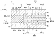
- FIG. 4 is a cross-sectional view showing the outer peripheral portion of the electrolytic cell 11.
- the electrolysis cell 11 has, for example, a support portion 60 and a sealing portion 70 in addition to the configuration described above.
- the support portion 60 is a component that supports the ion exchange membrane 43 inside the electrolytic cell 11 .
- the support portion 60 is arranged between the first separator 41 and the second separator 42 .
- the support portion 60 is located inside (inner peripheral side) of the outer edge portion 43 e of the ion exchange membrane 43 and supports the ion exchange membrane 43 .
- “inner side” or “inner peripheral side” means an inner side (closer to the central portion C) of the ion exchange membrane 43 when viewed from the central portion C (see FIG. 5).
- the support portion 60 includes a first support portion 61 and a second support portion 62 .
- the first support portion 61 is a support portion on the anode side.
- the first support portion 61 is arranged between the first inner surface 41 a of the first separator 41 and the ion exchange membrane 43 .
- the first support portion 61 is located inside the outer edge portion 43 e of the ion exchange membrane 43 .
- the first supporting portion 61 is sandwiched between the first inner surface 41 a of the first separator 41 and the ion exchange membrane 43 and supports the ion exchange membrane 43 against the first inner surface 41 a of the first separator 41 .
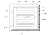
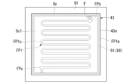
- FIG. 5 is a cross-sectional view along line F5-F5 of the electrolytic cell 11 shown in FIG.
- the first support portion 61 is formed in an annular shape (for example, a frame shape) along the outer edge portion 43 e of the ion exchange membrane 43 and in an annular shape that is slightly smaller than the outer edge portion 43 e of the ion exchange membrane 43 .
- the first support portion 61 extends along the outer edge portion 43 e of the ion exchange membrane 43 over the entire circumference of the ion exchange membrane 43 .
- the first supporting portion 61 supports the ion exchange membrane 43 along the entire periphery of the ion exchange membrane 43 .
- the first support portion 61 has a frame shape that is slightly larger than the region where the first flow path FP1 is provided and the first feeder 45 in the first inner surface 41 a of the first separator 41 .
- the first power feeder 45 is arranged inside (inner peripheral side) of the first support portion 61 .
- the first support portion 61 has elasticity and is compressed between the first inner surface 41 a of the first separator 41 and the ion exchange membrane 43 .
- the first support portion 61 applies a pressing force to the ion exchange membrane 43 by being compressed. Thereby, the ion exchange membrane 43 is supported more firmly.
- the modulus of elasticity of the first supporting portion 61 is higher than that of the first sealing portion 71, which will be described later.
- the material of the first support portion 61 is, for example, rubber, but is not particularly limited.
- the first support portion 61 is made of a material with excellent chemical resistance, it is suitable when a potassium hydroxide electrolyte (KOH electrolyte) or the like is used as the electrolyte.
- the first support portion 61 is airtight or liquid-tight, and functions as a sealing portion that seals between the first inner surface 41a of the first separator 41 and the ion exchange membrane 43. good too.
- the second support portion 62 is a support portion on the cathode side.
- the second support portion 62 is arranged between the second inner surface 42 a of the second separator 42 and the ion exchange membrane 43 .
- the second support portion 62 is located inside the outer edge portion 43 e of the ion exchange membrane 43 .
- the second support portion 62 is sandwiched between the second inner surface 42 a of the second separator 42 and the ion exchange membrane 43 and supports the ion exchange membrane 43 against the second inner surface 42 a of the second separator 42 .
- the shape of the second support portion 62 is the same as the shape of the first support portion 61 . That is, the second support portion 62 is formed in an annular shape (for example, a frame shape) along the outer edge portion 43 e of the ion exchange membrane 43 and in an annular shape that is slightly smaller than the outer edge portion 43 e of the ion exchange membrane 43 .
- the second support portion 62 extends along the outer edge portion 43 e of the ion exchange membrane 43 over the entire circumference of the ion exchange membrane 43 .
- the second support portion 62 supports the ion exchange membrane 43 along the entire circumference of the ion exchange membrane 43 .
- the second support part 62 has a frame shape that is slightly larger than the area where the second flow path FP2 is provided in the second inner surface 42 a of the second separator 42 and the second feeder 47 .
- the second power feeder 47 is arranged inside (inner peripheral side) of the second support portion 62 .
- the second support part 62 has elasticity and is compressed between the second inner surface 42 a of the second separator 42 and the ion exchange membrane 43 .
- the second support portion 62 applies a pressing force to the ion exchange membrane 43 by being compressed. Thereby, the ion exchange membrane 43 is supported more firmly.
- the elastic modulus of the second support portion 62 is higher than that of the second sealing portion 72, which will be described later. If the elastic modulus of the second support portion 62 is relatively large, damage to the ion exchange membrane 43 is suppressed.
- the material of the second support portion 62 is, for example, rubber, but is not particularly limited.
- the second support portion 62 is formed of a material with excellent chemical resistance, it is suitable when a potassium hydroxide electrolyte or the like is used as the electrolyte.
- the second support portion 62 is airtight or liquid-tight, and functions as a sealing portion that seals between the second inner surface 42a of the second separator 42 and the ion exchange membrane 43. good too.
- the support part 60 is separate from the sealing part 70 described later, and is arranged apart from the sealing part 70 .
- a space Se (hereinafter referred to as “end space Se”) that is part of the internal space S exists between the support portion 60 and the sealing portion 70 .
- the end space Se is a space in which the outer edge portion 43e of the ion exchange membrane 43 is located and which can accommodate an electrolytic solution.
- the end space Se is a space that is sealed from the outside by a sealing portion 70 that will be described later.
- first central space Sc1 a space Sc1 (hereinafter referred to as "first central space Sc1") is formed inside the first support portion 61 in the internal space S of the electrolytic cell 11.
- the first central space Sc1 is part of the anode chamber Sa, and accommodates the first catalyst layer 44 and the first power feeder 45 .
- second central space Sc2 a space Sc2 (hereinafter referred to as "second central space Sc2") is formed inside the second support portion 62 in the internal space S of the electrolytic cell 11.
- the second central space Sc2 is part of the cathode chamber Sb and accommodates the second catalyst layer 46 and the second power feeder 47 .
- the sealing part 70 is a component that seals the internal space S of the electrolytic cell 11 .
- the sealing portion 70 is arranged between the first separator 41 and the second separator 42 .
- the sealing portion 70 is positioned outside (on the outer peripheral side) of the outer edge portion 43 e of the ion exchange membrane 43 and seals the internal space S of the electrolytic cell 11 .
- “outer side” or “peripheral side” means the inner side (far side from the central portion C) of the ion exchange membrane 43 when viewed from the central portion C (see FIG. 5).
- the sealing portion 70 includes a first sealing portion 71 and a second sealing portion 72 .
- the first sealing portion 71 and the second sealing portion 72 may be integrally formed. That is, the first sealing portion 71 and the second sealing portion 72 may be one member.
- the first sealing portion 71 is a sealing portion on the anode side.
- the first sealing portion 71 is arranged between the first inner surface 41 a of the first separator 41 and the second inner surface 42 a of the second separator 42 .
- the first sealing portion 71 is located outside the outer edge portion 43 e of the ion exchange membrane 43 .
- the first sealing portion 71 is sandwiched between the first inner surface 41a of the first separator 41 and the second sealing portion 72, and seals a part of the outer peripheral side of the end space Se.
- the first sealing portion 71 is formed in an annular shape (for example, a frame shape) along the outer edge portion 43 e of the ion exchange membrane 43 and in an annular shape that is slightly larger than the outer edge portion 43 e of the ion exchange membrane 43 . be done.
- the first sealing portion 71 extends along the outer edge portion 43 e of the ion exchange membrane 43 over the entire circumference of the ion exchange membrane 43 .
- the first sealing portion 71 seals the outer peripheral side of the end space Se over the entire circumference of the ion exchange membrane 43 .
- the first sealing portion 71 has elasticity and is compressed between the first inner surface 41 a of the first separator 41 and the second sealing portion 72 . By being compressed, the first sealing portion 71 more firmly closes the space between the first separator 41 and the second separator 42 .
- the material of the first sealing portion 71 is, for example, rubber, but is not particularly limited.
- the second sealing portion 72 is a sealing portion on the cathode side.
- the second sealing portion 72 is arranged between the first inner surface 41 a of the first separator 41 and the second inner surface 42 a of the second separator 42 .
- the second sealing portion 72 is located outside the outer edge portion 43 e of the ion exchange membrane 43 .
- the second sealing portion 72 is sandwiched between the second inner surface 42a of the second separator 42 and the first sealing portion 71, and seals part of the outer peripheral side of the end space Se.
- the shape of the second sealing portion 72 is the same as the shape of the first sealing portion 71 . That is, the second sealing portion 72 is formed in an annular shape (for example, a frame shape) along the outer edge portion 43 e of the ion exchange membrane 43 and in an annular shape that is slightly larger than the outer edge portion 43 e of the ion exchange membrane 43 .
- the second sealing portion 72 extends along the outer edge of the ion exchange membrane 43 over the entire circumference of the ion exchange membrane 43 .
- the second sealing portion 72 seals the outer peripheral side of the end space Se over the entire circumference of the ion exchange membrane 43 .
- the second sealing portion 72 has elasticity and is compressed between the second inner surface 42 a of the second separator 42 and the first sealing portion 71 .
- the second sealing portion 72 is compressed to more firmly close the space between the first separator 41 and the second separator 42 .
- the material of the second sealing portion 72 is, for example, rubber, but is not particularly limited.
- the sealing portion 70 is made of a material that is highly resistant to both air and electrolyte compared to the support portion 60 .
- the sealing portion 70 is made of a material having higher heat resistance than the supporting portion 60 .
- a first inner surface 41 a of the first separator 41 has an end region 41 h located outside the first support portion 61 .
- the first insulator 53 is attached to the first inner surface 41a of the first separator 41 and covers the end region 41h of the first inner surface 41a.
- the first insulator 53 is provided over the position overlapping the first support portion 61 in the Z direction and the outer peripheral edge 41p of the first separator 41 .
- FIG. 6 is a cross-sectional view of the electrolytic cell 11 shown in FIG. 4 along line F6-F6.
- the first insulator 53 includes a portion located inside the outer edge portion 43 e of the ion exchange membrane 43 in addition to the portion located outside the outer edge portion 43 e of the ion exchange membrane 43 .
- the first insulator 53 may include at least a portion located outside the outer edge portion 43 e of the ion exchange membrane 43 . That is, the first insulator 53 may be provided only in a region that does not overlap the ion exchange membrane 43 in the Z direction.
- a second inner surface 42 a of the second separator 42 has an end region 42 h located outside the second support portion 62 .
- a second insulator 54 is attached to the second inner surface 42a of the second separator 42 and covers the end region 42h of the second inner surface 42a.
- the second insulator 54 is provided over the position overlapping the second support portion 62 in the Z direction and the outer peripheral edge 42p of the second separator 42 .
- the second insulator 54 includes a portion located inside the outer edge portion 43 e of the ion exchange membrane 43 in addition to the portion located outside the outer edge portion 43 e of the ion exchange membrane 43 .
- the second insulator 54 may include at least a portion located outside the outer edge portion 43 e of the ion exchange membrane 43 . That is, the second insulator 54 may be provided only in a region that does not overlap the ion exchange membrane 43 in the Z direction.
- first insulator 53 and the second insulator 54 form an insulating portion 55 that insulates between the outer peripheral portion of the first separator 41 and the outer peripheral portion of the second separator 42 .
- one of the first insulator 53 and the second insulator 54 may be omitted.
- the dry state and wet state may be repeated at or near the outer edge of the ion exchange membrane depending on the outside air temperature, humidity, or water vapor content.
- the ion-exchange membrane When the ion-exchange membrane is repeatedly put in a dry state and a wet state, the ion-exchange membrane expands and contracts due to the difference in water content. At this time, stress is repeatedly applied to the ion-exchange membrane pressurized by a sealing material, packing, etc., and deterioration is accelerated. In this case, as the deterioration progresses, the water permeability and gas permeability of the ion-exchange membrane increase, or cracks occur, causing leakage of water or gas.
- the outer edge of the ion-exchange membrane or a portion near it may become completely dry.
- the ion-exchange membrane becomes brittle, and voids and cracks occur inside the ion-exchange membrane.
- the water permeability and gas permeability of the ion exchange membrane increase, causing water leakage and gas leakage.
- the electrolytic cell 11 includes a support portion 60 positioned inside the outer edge portion 43e of the ion exchange membrane 43 to support the ion exchange membrane 43, and a support portion 60 positioned outside the outer edge portion 43e of the ion exchange membrane 43. and a sealing portion 70 positioned to seal the internal space S.
- the sealing portion 70 is arranged outside the outer edge portion 43e of the ion exchange membrane 43, it is possible to prevent the outer edge portion 43e of the ion exchange membrane 43 from being exposed to the outside air and being dried. can be done.
- the support portion 60 and the sealing portion 70 are arranged apart from each other, and the outer edge portion 43e of the ion exchange membrane 43 is positioned between the support portion 60 and the sealing portion 70 and contains the electrolytic solution.
- the outer edge portion 43e of the ion exchange membrane 43 is located in the wet end space Se where the electrolyte or the gas from which the electrolyte has evaporated exists, and is more difficult to dry. Thereby, the deterioration of the ion exchange membrane 43 can be suppressed at a higher level.
- FIG. 7 is a cross-sectional view showing the outer peripheral portion of the electrolytic cell 11 of the first modified example.
- at least one (for example, both) of the first support portion 61 and the second support portion 62 has a composition that allows passage of the electrolytic solution.
- the first supporting portion 61 and the second supporting portion 62 are formed of a porous material and have fine pores or voids through which the electrolytic solution can pass.
- the material of the first support portion 61 and the second support portion 62 is polyurethane foam, polyester, or the like, but is not particularly limited.
- the first support portion 61 allows the electrolytic solution supplied from the first flow path FP1 to the first central space Sc1 (the electrolytic solution supplied to the anode chamber Sa) to pass through toward the end space Se.
- the second support portion 62 allows the electrolytic solution supplied from the second flow path FP2 to the second central space Sc2 (the electrolytic solution supplied to the cathode chamber Sb) to pass through toward the end space Se.
- the electrolyte solution is supplied to the end space Se, and the end space Se tends to become more wet. Therefore, the outer edge portion 43e of the ion exchange membrane 43 is more difficult to dry, and deterioration of the ion exchange membrane 43 can be suppressed to a higher level.
- FIG. 8 is a cross-sectional view showing the outer peripheral portion of the electrolytic cell 11 of the second modified example.
- at least one (for example, both) of the first support portion 61 and the second support portion 62 has a through hole 81 through which the electrolytic solution can pass.
- one end of the through hole 81 of the first support portion 61 opens into the first central space Sc1.
- the other end of the through hole 81 of the first support portion 61 opens into the end space Se.
- the through hole 81 of the first support portion 61 allows the electrolytic solution supplied to the first central space Sc1 to pass toward the end space Se.
- one end of the through hole 81 of the second support portion 62 opens into the second central space Sc2.
- the other end of the through hole 81 of the second support portion 62 opens into the end space Se.
- the through hole 81 of the second support portion 62 allows the electrolytic solution supplied to the second central space Sc2 to pass toward the end space Se.
- the electrolytic solution is supplied to the end space Se through the through hole 81, and the end space Se tends to become more wet. Therefore, the outer edge portion 43e of the ion exchange membrane 43 is more difficult to dry, and deterioration of the ion exchange membrane 43 can be suppressed to a higher level.
- FIG. 9 is a cross-sectional view showing the outer peripheral portion of the electrolytic cell 11 of the third modified example.
- at least one (for example, both) of the first support portion 61 and the second support portion 62 has a groove 82 through which the electrolytic solution can pass.
- one end of the groove 82 of the first support portion 61 communicates with the first central space Sc1.
- the other end of the groove 82 of the first support portion 61 communicates with the end space Se.
- the groove 82 of the first support portion 61 allows the electrolytic solution supplied to the first central space Sc1 to pass toward the end space Se.
- one end of the groove 82 of the second support portion 62 communicates with the second central space Sc2.
- the other end of the groove 82 of the second support portion 62 communicates with the end space Se.
- the groove 82 of the second support portion 62 allows the electrolytic solution supplied to the second central space Sc2 to pass toward the end space Se.
- the electrolytic solution is supplied to the end space Se through the groove 82, and the end space Se tends to become more wet. Therefore, the outer edge portion 43e of the ion exchange membrane 43 is more difficult to dry, and deterioration of the ion exchange membrane 43 can be suppressed to a higher level.
- FIG. 10 is a cross-sectional view showing an electrolytic cell 11 of a fourth modified example.
- at least one (for example, both) of the first support portion 61 and the second support portion 62 is divided into a plurality of portions 60a in the extending direction, and the electrolytic solution can pass between these portions 60a.
- a divided portion 60b is formed.
- the dividing portion 60b of the first support portion 61 allows the electrolytic solution supplied to the first central space Sc1 to pass toward the end space Se.
- the dividing portion 60b of the second support portion 62 allows the electrolytic solution supplied to the second central space Sc2 to pass toward the end space Se.
- the electrolytic solution is supplied to the end space Se through the dividing portion 60b, and the end space Se tends to become more wet. Therefore, the outer edge portion 43e of the ion exchange membrane 43 is more difficult to dry, and deterioration of the ion exchange membrane 43 can be suppressed to a higher level.
- the second embodiment differs from the first embodiment in that the support portion 60 and the sealing portion 70 are integrally formed. Configurations other than those described below are the same as those of the first embodiment.
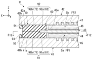
- FIG. 11 is a cross-sectional view showing the outer peripheral portion of the electrolytic cell 11 of the second embodiment.
- the electrolytic cell 11 includes a first packing 91 , a second packing 92 , a first stopper 93 and a second stopper 94 .
- the first packing 91 is an insulating member having airtightness.
- the first packing 91 includes a first portion 91a and a second portion 91b.
- the first portion 91a is a portion facing the ion exchange membrane 43 in the Z direction.
- the first portion 91 a is sandwiched between the first inner surface 41 a of the first separator 41 and the ion exchange membrane 43 and supports the ion exchange membrane 43 against the first inner surface 41 a of the first separator 41 .
- At least part of the first portion 91a functions as the first support portion 61 described above.
- the second portion 91 b is a portion located outside the outer edge portion 43 e of the ion exchange membrane 43 .
- the second portion 91b has a step with respect to the first portion 91a.
- the second portion 91b protrudes closer to the second separator 42 than the first portion 91a.
- a portion of the second portion 91b faces the ion exchange membrane 43 in the X direction.
- part of the second portion 91b contacts the ion exchange membrane 43 in the X direction. This restricts the displacement of the ion exchange membrane 43 in the X direction.
- the second portion 91b is in contact with a second portion 92b of a second packing 92, which will be described later, in the Z direction.
- the second portion 91b is sandwiched between the first inner surface 41a of the first separator 41 and the second packing 92, and seals part of the outer peripheral side of the end space Se.
- the second portion 91b functions as the first sealing portion 71 described above.
- FIG. 12 is a cross-sectional view of the electrolytic cell 11 shown in FIG. 11 taken along line F12-F12.
- the first packing 91 has a frame shape along the outer edge portion 43 e of the ion exchange membrane 43 .
- the first packing 91 extends along the outer edge of the ion exchange membrane 43 over the entire circumference of the ion exchange membrane 43 .
- the first packing 91 supports the ion exchange membrane 43 along the entire periphery of the ion exchange membrane 43 and seals the outer peripheral side of the internal space S along the entire periphery of the ion exchange membrane 43 .
- the second packing 92 is an insulating member having airtightness.
- the second packing 92 includes a first portion 92a and a second portion 92b.
- the first portion 92a is a portion facing the ion exchange membrane 43 in the Z direction.
- the first portion 92 a is sandwiched between the second inner surface 42 a of the second separator 42 and the ion exchange membrane 43 and supports the ion exchange membrane 43 against the second inner surface 42 a of the second separator 42 .
- At least part of the first portion 92a functions as the second support portion 62 described above.
- the ion exchange membrane 43 is sandwiched and fixed between the first portion 91 a of the first packing 91 and the first portion 92 a of the second packing 92 .
- the second portion 92b is a portion located outside the outer edge portion 43e of the ion exchange membrane 43.
- the second portion 92b has a step with respect to the first portion 92a.
- the second portion 92b protrudes closer to the first separator 41 than the first portion 92a.
- a portion of the second portion 92b faces the ion exchange membrane 43 in the X direction.
- part of the second portion 92b contacts the ion exchange membrane 43 in the X direction. This restricts the displacement of the ion exchange membrane 43 in the X direction.
- the second portion 92b contacts the second portion 91b of the first packing 91 in the Z direction.
- the second portion 92b is sandwiched between the second inner surface 42a of the second separator 42 and the first packing 91, and seals part of the outer peripheral side of the end space Se.
- the second portion 92b functions as the second sealing portion 72 described above.
- the insulating portion 55 is formed by the first packing 91 and the second packing 92 to provide insulation between the outer peripheral portion of the first separator 41 and the outer peripheral portion of the second separator 42. formed.
- the second packing 92 like the first packing 91, has a frame shape along the outer edge 43e of the ion exchange membrane 43. As shown in FIG. The second packing 92 is arranged along the outer edge portion 43 e of the ion exchange membrane 43 over the entire circumference of the ion exchange membrane 43 . The second packing 92 supports the ion exchange membrane 43 along the entire circumference of the ion exchange membrane 43 and seals the outer peripheral side of the internal space S along the entire circumference of the ion exchange membrane 43 .
- the first stopper 93 is a fixing portion that fixes the first packing 91 so that the first packing 91 does not come off to the outside.
- the first stopper 93 is fixed to the first separator 41 .
- the first stopper 93 contacts the first packing 91 from the outside.
- the first stopper 93 may be omitted when the first packing 91 is fixed to the first separator 41 or otherwise configured to prevent the first packing 91 from coming off or to be aligned.
- the second stopper 94 is a fixing portion that fixes the second packing 92 so that the second packing 92 does not come off to the outside.
- the second stopper 94 is fixed to the second separator 42 .
- the second stopper 94 contacts the second packing 92 from the outside.
- the second stopper 94 may be omitted when the second packing 92 is fixed to the second separator 42 or otherwise configured to prevent the second packing 92 from coming off or to be aligned.
- the third embodiment is different from the first embodiment in that end passages FP1e and FP2e are provided to flow the electrolytic solution into the end space Se. Configurations other than those described below are the same as those of the first embodiment.
- FIG. 13 is a cross-sectional view showing the outer peripheral portion of the electrolytic cell 11 of the third embodiment.
- the first packing 91 has only the second portion 91b and does not have the first portion 91a.
- the second packing 92 has only the second portion 92b and does not have the first portion 92a.
- the first flow path FP1 of the first separator 41 has a first central flow path FP1c and a first end flow path FP1e.
- the first central flow path FP1c corresponds to the first flow path FP1 described in the first embodiment. That is, the first central flow path FP1c is provided inside the first support portion 61 in the first inner surface 41a of the first separator 41 .
- the first end channel FP1e is a channel capable of supplying an electrolytic solution to the end space Se.
- the first end flow path FP1e is provided, for example, in the end region 41h of the first inner surface 41a of the first separator 41 (that is, the region outside the first support portion 61).
- the first end flow path FP1e is, for example, a groove provided in the first inner surface 41a.
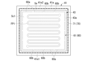
- FIG. 14 is a cross-sectional view of the electrolytic cell 11 shown in FIG. 13 along line F14-F14.
- FIG. 14 shows only one of the plurality of first end flow paths FP1e shown in FIG.
- the first flow path FP1 has an inlet FPa and an outlet FPb.
- the inlet FPa communicates with the piping line L1, and the electrolytic solution flows in from the piping line L1.
- the outflow port FPb communicates with the piping line L2, and the electrolytic solution that has passed through the electrolytic cell 11 is discharged toward the piping line L2.
- the first end flow path FP1e branches off from the first central flow path FP1c at the inlet FPa.
- the first end channel FP1e passes through the end region 41h of the first separator 41 and joins the first central channel FP1c at the outlet FPb.
- the first end flow path FP1e and the first central flow path FP1c may be continuous. That is, the electrolytic solution flowing from the inlet FPa may flow into the first central flow channel FP1c after flowing through the first end flow channel FP1e. After flowing through the first central flow path FP1c, the liquid may flow into the first end flow path FP1e.
- a filter F may be provided that allows the passage of gas (hydrogen or oxygen) but restricts the passage of the gas. As such a filter F, it is possible to employ a filter having fine mesh through which gas is difficult to pass.
- the second flow path FP2 (Second flow path) Returning to FIG. 13, the second flow path FP2 will be described.
- the second flow path FP2 of the second separator 42 has a second central flow path FP2c and a second end flow path FP2e.
- the second central flow path FP2c corresponds to the second flow path FP2 described in the first embodiment. That is, the second central flow path FP2c is provided inside the second support portion 62 in the second inner surface 42a of the second separator 42 .
- the second end channel FP2e is a channel capable of supplying an electrolytic solution to the end space Se.
- the second end flow path FP2e is provided, for example, in an end region 42h of the second inner surface 42a of the second separator 42 (that is, a region outside the second support portion 62).
- the second end flow path FP2e is, for example, a groove provided in the second inner surface 42a. Similar to the relationship between the first end flow path FP1e and the first central flow path FP1c, the second end flow path FP2e may be a flow path branched from the second central flow path FP2c. It may be a channel continuous with .
- the electrolyte solution is supplied to the end space Se through the end flow paths FP1e and FP2e, and the end space Se tends to become more wet. Therefore, the outer edge portion 43e of the ion exchange membrane 43 is more difficult to dry, and deterioration of the ion exchange membrane 43 can be suppressed to a higher level.
- the first end channel FP1e branches from the first central channel FP1c at a position closer to the inlet FPa than to the outlet FPb.
- Such a configuration makes it difficult for the gas generated by electrolysis to flow into the first end flow path FP1e. As a result, the electrolytic solution is easily supplied to the end space Se.
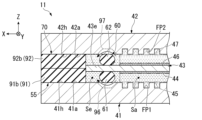
- FIG. 15 is a cross-sectional view showing the outer peripheral portion of an electrolytic cell 11 of a modification of the third embodiment.
- the first inner surface 41a of the first separator 41 has grooves 96 through which the electrolytic solution can pass.
- the groove 96 is provided so as to straddle the first support portion 61 in the X direction, and allows the electrolytic solution supplied to the first central space Sc1 to pass toward the end space Se.
- the groove 96 is an example of a channel capable of supplying the electrolyte solution to the end space Se.
- the second inner surface 42a of the second separator 42 has grooves 97 through which the electrolytic solution can pass.
- the groove 97 is provided so as to straddle the second support portion 62 in the X direction, and allows the electrolytic solution supplied to the second central space Sc2 to pass toward the end space Se.
- the groove 97 is an example of a channel capable of supplying the electrolyte solution to the end space Se.
- the electrolytic solution can be supplied to the end space Se also by such a channel. That is, the flow path capable of supplying the electrolyte solution to the end space Se is not limited to flow paths having the same shape as the central flow paths FP1c and FP2c.
- the electrolytic cell 11, the electrolytic cell stack 10, and the electrolytic device 1 are not limited to devices that generate hydrogen, and can be used as devices that electrolytically reduce carbon dioxide.
- a carbon dioxide-containing substance is supplied to the cathode chamber Sb, and a carbon dioxide-reducing substance is produced in the cathode chamber Sb.
- the carbon dioxide reducing substance includes at least one of carbon monoxide, formic acid, formate, alcohol, and hydrocarbon.
- the alcohol is, for example, methanol or ethanol.
- Said hydrocarbons are, for example, methane, ethylene or acetylene.
- the electrolytic cell 11 includes a first separator 41, a second separator 42 arranged with a space (internal space S) between the first separator 41 and the first separator 41 and the second separator 42, and divides at least part of the space into an anode chamber Sa and a cathode chamber Sb, and the first separator 41 and the second separator 42. and a sealing portion 70 located outside the outer edge portion 43e of the ion exchange membrane 43 and sealing the space.
- the sealing portion 70 is arranged outside the outer edge portion 43e of the ion exchange membrane 43, it is possible to prevent the outer edge portion 43e of the ion exchange membrane 43 from being exposed to the outside air and being dried. can be done. As a result, it is possible to prevent the outer edge 43e of the ion exchange membrane 43 and the portion near the outer edge 43e from repeating the dry state and the wet state and from becoming completely dry. Thereby, deterioration of the ion exchange membrane 43 can be suppressed.
- the electrolytic cell 11 according to the second aspect is the electrolytic cell 11 according to the first aspect, and is arranged between the first separator 41 and the second separator 42, and the outer edge portion of the ion exchange membrane 43 An insulating portion 55 including a portion located outside 43e may be further provided. According to such a configuration, the first separator 41 and the second separator 41 and the second separator 41 and the second separator 41 are separated from each other even in a portion where the ion exchange membrane 43 does not exist because the ion exchange membrane 43 has a smaller outer shape than the first separator 41 or the second separator 42 . A short circuit with the separator 42 can be prevented.
- the electrolytic cell 11 according to the third aspect is the electrolytic cell 11 according to the first or second aspect, and is arranged between the first separator 41 and the second separator 42, and the ion exchange membrane 43 A supporting portion 60 positioned inside the outer edge portion 43e of the ion exchange membrane 43 and supporting the ion exchange membrane 43 may be further provided.
- the ion exchange membrane 43 can be supported by the supporting portion 60 at a position inside the outer edge portion 43 e of the ion exchange membrane 43 .
- the ion exchange membrane 43 can be stably supported.
- mixing of the oxygen gas generated in the anode chamber Sa and the hydrogen gas generated in the cathode chamber Sb is suppressed, thereby improving safety. and/or, when the solution compositions of the cathode chamber Sb and the anode chamber Sa are different, mixing of the two can be easily suppressed.
- the electrolytic cell 11 according to the third aspect is the electrolytic cell 11 according to the third aspect, in which the support portion 60 and the sealing portion 70 extend along the outer edge portion 43e of the ion exchange membrane 43.
- the support portion 60 and the sealing portion 70 extend along the outer edge portion 43e of the ion exchange membrane 43.
- the electrolytic cell 11 according to the fifth aspect is the electrolytic cell 11 according to the third or fourth aspect, in which the support portion 60 and the sealing portion 70 are arranged apart from each other, and the support portion 60 and the sealing portion 70, there may be an end space Se in which the outer edge portion 43e of the ion-exchange membrane 43 is located and in which the electrolytic solution can be accommodated.
- the outer edge portion 43e of the ion exchange membrane 43 is located in the wet end space Se where the electrolyte or the gas from which the electrolyte has evaporated exists, and is more difficult to dry. Thereby, the deterioration of the ion exchange membrane 43 can be suppressed at a higher level.
- the electrolytic cell 11 according to the sixth aspect is the electrolytic cell 11 according to the fifth aspect, in which the supporting portion 60 is annular along the outer edge portion 43e of the ion exchange membrane 43,
- the sealing portion 70 is formed in an annular shape smaller than the outer edge portion 43 e of the ion exchange membrane 43 , and is formed in an annular shape along the outer edge portion 43 e of the ion exchange membrane 43 and larger than the outer edge portion 43 e of the ion exchange membrane 43 .
- Annular in the present disclosure is not limited to a circular ring, but may also include a rectangular ring.
- annular as used in the present disclosure is not limited to a continuous ring, and may include a ring that includes a portion that is divided in the middle. According to such a configuration, the supporting portion 60 and the sealing portion 70 can form an annular end space Se corresponding to the entire circumference of the outer edge portion 43 e of the ion exchange membrane 43 . Thereby, the deterioration of the ion exchange membrane 43 can be suppressed at a higher level.
- the electrolysis cell 11 according to the seventh aspect is the electrolysis cell 11 according to any one of the third to sixth aspects, and the support part 60 is supplied to the anode chamber Sa or the cathode chamber Sb. It may have a composition or structure that allows the electrolyte solution to pass toward the end space Se. According to such a configuration, the electrolytic solution supplied to the anode chamber Sa or the cathode chamber Sb can flow into the end space Se, and the end space Se can be filled with a larger amount of the electrolytic solution. As a result, the outer edge portion 43e of the ion exchange membrane 43 becomes more difficult to dry. As a result, deterioration of the ion exchange membrane 43 can be suppressed at a higher level.
- the electrolytic cell 11 according to the eighth aspect is the electrolytic cell 11 according to any one of the third to seventh aspects, and between the support portion 60 and the sealing portion 70, There is an end space Se in which the outer edge portion 43e of the ion exchange membrane 43 is located and which can accommodate an electrolytic solution, and at least one of the first separator 41 and the second separator 42 can supply the electrolytic solution to the end space Se. flow paths (end flow paths FP1e, FP2e). According to such a configuration, the end space Se can be filled with a larger amount of electrolytic solution by the flow path. As a result, the outer edge portion 43e of the ion exchange membrane 43 becomes more difficult to dry. As a result, deterioration of the ion exchange membrane 43 can be suppressed at a higher level.
- the electrolytic cell 11 according to the ninth aspect is the electrolytic cell 11 according to the third or fourth aspect, and the support portion 60 and the sealing portion 70 may be integrally formed. According to such a configuration, it is possible to improve workability of attaching the support portion 60 and the sealing portion 70 compared to the case where the support portion 60 and the sealing portion 70 are provided separately. As a result, the manufacturability of the electrolytic cell 11 can be improved.
- the electrolytic cell 11 according to the tenth aspect is the electrolytic cell 11 according to the ninth aspect, in which a first packing 91 including part of the support portion 60 and part of the sealing portion 70; A second packing 92 that includes another portion of the support portion 60 and another portion of the sealing portion 70 and sandwiches the ion exchange membrane 43 between itself and the first packing 91 may be provided. According to such a configuration, by sandwiching the ion exchange membrane 43 between the first packing 91 and the second packing 92, the supporting portion 60 that supports the ion exchange membrane 43 and the outer peripheral side of the ion exchange membrane 43 are sealed. A sealing portion 70 is formed. Therefore, the manufacturability of the electrolytic cell 11 can be further improved.
- the electrolytic cell 11 according to the eleventh aspect is the electrolytic cell 11 according to any one of the first to tenth aspects, wherein the ion-exchange membrane 43 has hydroxide ion conductivity. It may be an anion exchange membrane.
- the electrolytic cell 11 according to the twelfth aspect is the electrolytic cell 11 according to the eleventh aspect, and hydrogen may be generated in the cathode chamber Sb.
- the electrolytic cell 11 according to the thirteenth aspect is the electrolytic cell 11 according to the eleventh aspect, in which a carbon dioxide-containing substance is supplied to the cathode chamber Sb, and a carbon dioxide-reducing substance is produced in the cathode chamber Sb. may be
- the electrolytic cell 11 according to the fourteenth aspect is the electrolytic cell 11 according to the thirteenth aspect, wherein the carbon dioxide reducing substance is at least one of carbon monoxide, formic acid, formate, alcohol, and hydrocarbon. or one.
- the electrolytic device 1 according to the fifteenth aspect includes the electrolytic cell 11 according to any one of the first to fourteenth aspects, the electrolytic solution supply unit 20 that supplies the electrolytic solution to the electrolytic cell 11, and a power supply unit 30 that applies a voltage to the electrolytic cell 11 . According to such a configuration, deterioration of the ion exchange membrane 43 can be suppressed for the same reason as the electrolytic cell 11 according to the first aspect.
- An electrolysis device 1 according to a sixteenth aspect is the electrolysis device 1 according to the fifteenth aspect, comprising an electrolysis cell stack 10 having a plurality of electrolysis cells 11 including electrolysis cells 11, Two adjacent electrolysis cells 11 in the cell 11 may share the first separator 41 or the second separator 42, which are bipolar plates. According to such a configuration, it becomes easier to achieve miniaturization of the electrolysis cell stack 10 , and as a result, it becomes easier to achieve miniaturization of the electrolysis device 1 .
- Example 1 In the electrolysis device 1 according to the first embodiment, an anion exchange membrane is adopted as the ion exchange membrane 43 of the electrolysis cell 11, and a rubber sheet made of ethylene propylene resin (EPDM) is adopted as the support portion 60 and the sealing portion 70.
- EPDM ethylene propylene resin
- a test body was produced. The test specimen was held in a state simulating before and after exposure to the operating environment (environmental temperature: 60 degrees Celsius) of the electrolytic device 1, and an evaluation test was conducted. dimensional change was investigated. Also, for the evaluation of Example 1, specimens of Comparative Examples 1 and 2 were produced and held in the same state as in Example 1 to conduct an evaluation test. The process of the evaluation test performed for each specimen is as follows.
- a new and unused ion-exchange membrane 43 was prepared, and the supporting portion 60 and the sealing portion 70 were attached to the ion-exchange membrane 43 to obtain a specimen A. Rectangular measurement areas A-1, A-2, and A-3 of substantially the same size are set on one side surface of the ion exchange membrane 43 of the specimen A, and these measurement areas A-1, A-2, and A-3 are set. The length of the vertical side and the length of the horizontal side were measured for A-2 and A-3 (initial state).
- the specimen A, in which the supporting part 60 and the sealing part 70 were attached to the ion-exchange membrane 43 was immersed in an aqueous solution and left for a while (simulating before exposure to the operating environment).
- the ion exchange membrane 43 is removed from the aqueous solution, and the length of the vertical side and the horizontal side of the measurement regions A-1, A-2, and A-3 of the ion exchange membrane 43 swollen by the aqueous solution are measured. length was measured. (3) The ion-exchange membrane 43 swollen by the aqueous solution was placed in a low-humidity space for a while with the supporting portion 60 and the sealing portion 70 attached (simulating exposure to the operating environment). After a predetermined time had passed, the length of the vertical side and the length of the horizontal side of the measurement regions A-1, A-2, and A-3 of the dried ion exchange membrane 43 were recorded.
- Comparative example 1 As Comparative Example 1 for Example 1, the following test specimen was prepared, and the same evaluation test as in Example 1 was conducted to examine the dimensional change of the ion exchange membrane 43 before and after exposure to the operating environment. (1) A new and unused ion-exchange membrane 43 was prepared separately from Example 1, and a specimen B was obtained by attaching only the support portion 60 to this ion-exchange membrane 43 .
- the ion-exchange membrane 43 is removed from the aqueous solution, and the length of the vertical side and the horizontal side of the measurement regions B-1, B-2, and B-3 of the ion-exchange membrane 43 swollen by the aqueous solution are measured. length was measured. (3) The specimen B swollen by the aqueous solution was placed in a low-humidity space for a while with the supporting part 60 attached to the ion-exchange membrane 43 (simulating exposure to the operating environment). After a predetermined time had passed, the length of the vertical side and the length of the horizontal side of the measurement regions B-1, B-2, and B-3 of the dried ion-exchange membrane 43 were recorded.
- Comparative example 2 Furthermore, the following specimen was prepared as Comparative Example 2 for Example 1, and the same evaluation test as in Example 1 was conducted to examine the dimensional change of the ion exchange membrane 43 before and after exposure to the operating environment. (1) Separately from Example 1 and Comparative Example 1, a new and unused ion exchange membrane 43 was prepared, and neither the supporting portion 60 nor the sealing portion 70 was attached to the ion exchange membrane 43 to obtain a specimen C. .
- the ion-exchange membrane 43 is removed from the aqueous solution, and the length of the vertical side and the horizontal side of the measurement regions C-1, C-2, and C-3 of the ion-exchange membrane 43 swollen by the aqueous solution are measured. length was measured. (3) Specimen C swollen by the aqueous solution was placed in a low-humidity space and left for a while (simulating exposure to the operating environment). After a predetermined time had passed, the lengths of the vertical sides and the lengths of the horizontal sides of the measurement regions C-1, C-2, and C-3 of the dried ion-exchange membrane 43 were recorded.
- Example 1 For each of Example 1, Comparative Example 1, and Comparative Example 2, the length of the vertical side of the region to be measured of the ion-exchange membrane 43 in the initial state of new and unused was measured before and after exposure to the operating environment. The extent to which the length of the vertical sides of the area to be measured changed, and how the length of the horizontal sides of the area to be measured changed relative to the length of the horizontal sides of the area to be measured before and after exposure to the operating environment. The dimensional change rate (%) was used to evaluate whether there was any change.
- 16A, 16B and 16C, and 17A, 17B and 17C show measured values of the dimensional change rate of the ion exchange membrane 43 before and after exposure to the operating environment. Since the ion-exchange membrane 43 swells with the aqueous solution before exposure to the operating environment, the dimensional change rate of the measured region shows a positive value with respect to the initial state in both Example 1, Comparative Example 1, and Comparative Example 2. . After exposure to the operating environment, the ion exchange membrane 43 dries and shrinks, so the dimensional change rates of Comparative Examples 1 and 2 show negative values, and the vertical sides of the ion exchange membrane 43 are larger than those in the initial state. Both sides are short.
- Example 1 Although the dimensional change rate of Example 1 is smaller than before exposure to the operating environment, it still shows a positive value, and compared to Comparative Examples 1 and 2, the wet state is clearly maintained. It can be seen that That is, according to the electrolytic device 1 according to the first embodiment, an effect of preventing drying of the ion exchange membrane 43 can be expected.
- the present disclosure relates to electrolytic cells and electrolytic devices. ADVANTAGE OF THE INVENTION According to this indication, deterioration of the ion-exchange membrane contained in an electrolytic cell can be suppressed.
- Electrolysis apparatus 10 Electrolysis cell stack 20
- Electrolyte solution supply part 30 Electrolysis cell 41
- First separator 42 Second separator 43
- Ion exchange membrane 44 ...
- First catalyst layer 45
- First power feeder 46 Second catalyst layer 47
- Second feeder 51 ...
- First current collector 52 Second current collector 53
- Support part 61 ...
- First Support portion 62 Second support portion 70 Sealing portion 71 First sealing portion 72 Second sealing portion 81 Through hole 82 Groove 91 First packing 92 Second packing 96 Groove 97 Groove S Internal space Sa Anode chamber Sb Cathode chamber Se End space Sc1 First central space Sc2 Second central space FP1 First flow channel FP1c First central flow channel FP1e First end flow channel FP2... second flow path FP2c... second central flow path FP2e... second end flow path
Abstract
An electrolytic cell according to the present disclosure comprises: a first separator; a second separator disposed so that a space is present between the second separator and the first separator; an ion exchange membrane disposed between the first separator and the second separator, the ion exchange membrane partitioning at least a part of the space into an anode chamber and a cathode chamber; and a sealing part disposed between the first separator and the second separator, the sealing part being disposed on the outer side with respect to the outer edge of the ion exchange membrane and sealing the space.
Description
本開示は、電解セル及び電解装置に関する。
本願は、2022年2月24日に出願された特願2022-26586号に対して優先権を主張し、その内容をここに援用する。 The present disclosure relates to electrolysis cells and electrolysis devices.
This application claims priority to Japanese Patent Application No. 2022-26586 filed on February 24, 2022, the contents of which are incorporated herein.
本願は、2022年2月24日に出願された特願2022-26586号に対して優先権を主張し、その内容をここに援用する。 The present disclosure relates to electrolysis cells and electrolysis devices.
This application claims priority to Japanese Patent Application No. 2022-26586 filed on February 24, 2022, the contents of which are incorporated herein.
特許文献1には、陽極室に水素ガス電極を設置し、当該水素ガス電極をイオン交換膜との反対面に密着させるとともに、当該水素ガス電極に対して水素と水分を含有する混合ガスを供給しながら塩を電解する電解分離方法が開示されている。この電解分離方法は、イオン交換膜の中央領域の乾燥防止を図るものである。
In Patent Document 1, a hydrogen gas electrode is installed in the anode chamber, the hydrogen gas electrode is brought into close contact with the opposite side of the ion exchange membrane, and a mixed gas containing hydrogen and moisture is supplied to the hydrogen gas electrode. An electrolytic separation method is disclosed in which the salt is electrolyzed while This electrolytic separation method is intended to prevent the central region of the ion exchange membrane from drying out.
特許文献2には、一対のセパレータの間に設けられ、陽極及び陰極が両面に形成された固体高分子電解質膜と、当該固体高分子電解質膜とセパレータの間に介装された給電体とからなる水電解セルであって、ガス溜まりが生じる部位を除いて電極形成面が形成された電解セルが開示されている。この電解セルは、給電体端部のガス滞留を解消することで、水電解効率の向上を図るものである。
In Patent Document 2, a solid polymer electrolyte membrane provided between a pair of separators and having an anode and a cathode formed on both sides, and a power feeder interposed between the solid polymer electrolyte membrane and the separator A water electrolysis cell is disclosed in which an electrode formation surface is formed except for a portion where a gas pool occurs. This electrolysis cell aims to improve the efficiency of water electrolysis by eliminating gas retention at the end of the feeder.
特許文献3には、開閉弁を開弁し、脱圧ラインを介してカソード側の圧力を脱圧する工程と、カソード側の脱圧が終了した後、上記開閉弁を開弁状態に維持したまま、常圧の水電解処理を行う工程とを含む高圧水素製造装置の運転停止方法が開示されている。この運転停止方法は、運転停止時の工程によりカソード側に良好な水分量を確保することで、固体高分子電解質膜の乾燥防止を図るものである。
Patent Document 3 discloses a process of opening an on-off valve to release the pressure on the cathode side through a depressurization line; , and a step of performing water electrolysis treatment at normal pressure. This shutdown method aims to prevent the solid polymer electrolyte membrane from drying out by securing a good amount of water on the cathode side through the process at the time of shutdown.
特許文献4には、セパレータに、水素排出連通孔を周回するシール部材と、当該シール部材を周回して水を流通させる水通路部とが設けられた電解装置が開示されている。この電解装置は、水素排出連通孔の近傍においてシール部材の外側部分が乾燥することを防止するものである。
Patent Document 4 discloses an electrolytic device in which a separator is provided with a seal member that encircles a hydrogen discharge passage and a water passage section that encircles the seal member and allows water to flow. This electrolytic device prevents the outer portion of the sealing member from drying out in the vicinity of the hydrogen discharge passage.
ところで、一対のセパレータの間にイオン交換膜を設けるとともに、イオン交換膜の外縁部よりも内側に電解槽の内部空間を封止する封止部を設ける場合、当該封止部よりも外側に突出するイオン交換膜の外縁部が乾燥しやすくなる場合がある。そして、イオン交換膜の外縁部が乾燥すると、イオン交換膜の劣化が進みやすくなるという問題がある。
By the way, when an ion-exchange membrane is provided between a pair of separators and a sealing portion for sealing the internal space of the electrolytic cell is provided inside the outer edge of the ion-exchange membrane, the sealing portion protrudes outward from the sealing portion. In some cases, the outer edge of the ion-exchange membrane, which is exposed to water, tends to dry out. Then, when the outer edge of the ion-exchange membrane dries, there is a problem that the ion-exchange membrane is likely to deteriorate.
本開示は、上記課題を解決するためになされたものであって、イオン交換膜の劣化の抑制を図ることができる電解セル及び電解装置を提供することを目的とする。
The present disclosure has been made to solve the above problems, and aims to provide an electrolytic cell and an electrolytic device capable of suppressing deterioration of ion exchange membranes.
上記課題を解決するために、本開示に係る電解セルは、第1セパレータと、前記第1セパレータとの間に空間を空けて配置される第2セパレータと、前記第1セパレータと前記第2セパレータとの間に配置され、前記空間の少なくとも一部を陰極室と陽極室とに区画するイオン交換膜と、前記第1セパレータと前記第2セパレータとの間に配置され、前記イオン交換膜の外縁部よりも外側に位置し、前記空間を封止する封止部と、を備える。
In order to solve the above problems, the electrolytic cell according to the present disclosure includes a first separator, a second separator arranged with a space between the first separator, the first separator and the second separator and an ion exchange membrane that divides at least part of the space into a cathode chamber and an anode chamber; a sealing portion located outside the portion and sealing the space.
本開示に係る電解装置は、電解セルと、前記電解セルに電解液を供給する電解液供給部と、前記電解セルに電圧を印加する電源部と、を備える。前記電解セルは、第1セパレータと、前記第1セパレータとの間に空間を空けて配置される第2セパレータと、前記第1セパレータと前記第2セパレータとの間に配置され、前記空間の少なくとも一部を陽極室と陰極室とに区画するイオン交換膜と、前記第1セパレータと前記第2セパレータとの間に配置され、前記イオン交換膜の外縁部よりも外側に位置し、前記空間を封止する封止部と、を備える。
An electrolytic device according to the present disclosure includes an electrolytic cell, an electrolytic solution supply section that supplies an electrolytic solution to the electrolytic cell, and a power supply section that applies voltage to the electrolytic cell. The electrolysis cell includes a first separator, a second separator that is arranged with a space between the first separator, and a separator that is arranged between the first separator and the second separator, and at least An ion-exchange membrane partially partitioned into an anode chamber and a cathode chamber, and an ion-exchange membrane disposed between the first separator and the second separator, positioned outside the outer edge of the ion-exchange membrane, and dividing the space. and a sealing portion for sealing.
本開示の電解セル及び電解装置によれば、イオン交換膜の劣化の抑制を図ることができる。
According to the electrolytic cell and electrolytic device of the present disclosure, deterioration of the ion exchange membrane can be suppressed.
以下、本開示の実施形態の電解セル及び電解装置を、図面を参照して説明する。以下の説明では、同一又は類似の機能を有する構成に同一の符号を付す。
An electrolysis cell and an electrolysis device according to embodiments of the present disclosure will be described below with reference to the drawings. In the following description, the same reference numerals are given to components having the same or similar functions.
先に図4を参照し、Z方向、X方向、及びY方向を定義する。Z方向は、後述する第1セパレータ41から第2セパレータ42に向かう方向である。X方向は、Z方向とは交差する(例えば直交する)方向であり、後述するイオン交換膜43の中央部からイオン交換膜43の一端部に向かう方向である。Y方向は、Z方向及びX方向とは交差する(例えば直交する)方向であり、例えば図4における紙面奥行方向である。
With reference to FIG. 4 above, the Z direction, X direction, and Y direction are defined. The Z direction is a direction from a first separator 41 to a second separator 42, which will be described later. The X direction is a direction crossing (for example, perpendicular to) the Z direction, and is a direction from the center of the ion exchange membrane 43 to one end of the ion exchange membrane 43, which will be described later. The Y direction is a direction that intersects (for example, is orthogonal to) the Z direction and the X direction, and is, for example, the depth direction of the paper surface in FIG.
(第1実施形態)
<1.電解装置の構成>
図1は、第1実施形態に係る電解装置1の全体構成を示す概略構成図である。電解装置1は、電解液に含まれる水を電気分解することで水素を生成する装置である。電解装置1は、例えば、アニオンイオン交換膜(AEM:Anion Exchange Membrane)式の電解装置である。ただし、電解装置1は、上記例に限定されず、二酸化炭素を電解還元する装置など異なるタイプの電解装置でもよい。 (First embodiment)
<1. Configuration of electrolytic device>
FIG. 1 is a schematic configuration diagram showing the overall configuration of anelectrolytic device 1 according to the first embodiment. The electrolytic device 1 is a device that generates hydrogen by electrolyzing water contained in an electrolytic solution. The electrolytic device 1 is, for example, an anion exchange membrane (AEM) type electrolytic device. However, the electrolytic device 1 is not limited to the above example, and may be a different type of electrolytic device such as a device for electrolytically reducing carbon dioxide.
<1.電解装置の構成>
図1は、第1実施形態に係る電解装置1の全体構成を示す概略構成図である。電解装置1は、電解液に含まれる水を電気分解することで水素を生成する装置である。電解装置1は、例えば、アニオンイオン交換膜(AEM:Anion Exchange Membrane)式の電解装置である。ただし、電解装置1は、上記例に限定されず、二酸化炭素を電解還元する装置など異なるタイプの電解装置でもよい。 (First embodiment)
<1. Configuration of electrolytic device>
FIG. 1 is a schematic configuration diagram showing the overall configuration of an
電解装置1は、例えば、電解セルスタック10と、電解液供給部20と、電源部30とを備える。
The electrolytic device 1 includes, for example, an electrolytic cell stack 10, an electrolytic solution supply section 20, and a power supply section 30.
(電解セルスタック)
電解セルスタック10は、複数の電解セル11の集合体である。例えば、電解セルスタック10は、複数の電解セル11が一方向に並べられることで形成される。各電解セル11は、陽極室Saと、陰極室Sbとを含む。電解セル11については、詳しく後述する。 (Electrolytic cell stack)
Theelectrolysis cell stack 10 is an assembly of a plurality of electrolysis cells 11 . For example, the electrolysis cell stack 10 is formed by arranging a plurality of electrolysis cells 11 in one direction. Each electrolytic cell 11 includes an anode chamber Sa and a cathode chamber Sb. The electrolytic cell 11 will be described later in detail.
電解セルスタック10は、複数の電解セル11の集合体である。例えば、電解セルスタック10は、複数の電解セル11が一方向に並べられることで形成される。各電解セル11は、陽極室Saと、陰極室Sbとを含む。電解セル11については、詳しく後述する。 (Electrolytic cell stack)
The
(電解液供給部)
電解液供給部20は、各電解セル11に電解液を供給する供給部である。電解液は、例えば、アルカリ水溶液である。電解液供給部20は、陽極側供給部20aと、陰極側供給部20bとを含む。 (Electrolyte solution supply unit)
The electrolyticsolution supply unit 20 is a supply unit that supplies the electrolytic solution to each electrolytic cell 11 . The electrolytic solution is, for example, an alkaline aqueous solution. The electrolytic solution supply section 20 includes an anode side supply section 20a and a cathode side supply section 20b.
電解液供給部20は、各電解セル11に電解液を供給する供給部である。電解液は、例えば、アルカリ水溶液である。電解液供給部20は、陽極側供給部20aと、陰極側供給部20bとを含む。 (Electrolyte solution supply unit)
The electrolytic
陽極側供給部20aは、各電解セル11の陽極室Saに電解液を供給する供給部である。陽極側供給部20aは、例えば、第1電解液タンク21、第1ポンプ22、酸素回収部23、第1電解液供給部24、及び配管ラインL1,L2を含む。
The anode-side supply part 20a is a supply part that supplies an electrolytic solution to the anode chamber Sa of each electrolytic cell 11. The anode-side supply section 20a includes, for example, a first electrolyte tank 21, a first pump 22, an oxygen recovery section 23, a first electrolyte supply section 24, and piping lines L1 and L2.
第1電解液タンク21は、電解液を貯留する。第1電解液タンク21の供給口は、配管ラインL1を介して電解セル11の陽極室Saに接続される。第1ポンプ22は、配管ラインL1の途中に設けられ、第1電解液タンク21に貯留された電解液を電解セル11の陽極室Saに向けて送る。
The first electrolytic solution tank 21 stores the electrolytic solution. A supply port of the first electrolytic solution tank 21 is connected to the anode chamber Sa of the electrolytic cell 11 via a piping line L1. The first pump 22 is provided in the middle of the pipeline L<b>1 and sends the electrolyte stored in the first electrolyte tank 21 toward the anode chamber Sa of the electrolytic cell 11 .
第1電解液タンク21の戻り口は、配管ラインL2を介して電解セル11の陽極室Saに接続される。第1電解液タンク21には、電解セル11で生成された酸素を含む電解液が電解セル11から流入する。第1電解液タンク21は、電解液に含まれる酸素を分離する気液分離部を有する。第1電解液タンク21により電解液から分離された酸素は、酸素回収部23によって回収される。第1電解液タンク21には、第1電解液供給部24から電解液が補充される。
A return port of the first electrolytic solution tank 21 is connected to the anode chamber Sa of the electrolytic cell 11 via a piping line L2. The oxygen-containing electrolyte generated in the electrolytic cell 11 flows from the electrolytic cell 11 into the first electrolytic solution tank 21 . The first electrolytic solution tank 21 has a gas-liquid separator that separates oxygen contained in the electrolytic solution. The oxygen separated from the electrolyte by the first electrolyte tank 21 is recovered by the oxygen recovery unit 23 . The first electrolytic solution tank 21 is replenished with the electrolytic solution from the first electrolytic solution supply section 24 .
一方で、陰極側供給部20bは、各電解セル11の陰極室Sbに電解液を供給する供給部である。陰極側供給部20bは、例えば、第2電解液タンク26、第2ポンプ27、水素回収部28、第2電解液供給部29、及び配管ラインL3,L4を含む。
On the other hand, the cathode-side supply section 20b is a supply section that supplies the electrolytic solution to the cathode chamber Sb of each electrolytic cell 11 . The cathode-side supply section 20b includes, for example, a second electrolyte tank 26, a second pump 27, a hydrogen recovery section 28, a second electrolyte supply section 29, and piping lines L3 and L4.
第2電解液タンク26は、電解液を貯留する。第2電解液タンク26の供給口は、配管ラインL3を介して電解セル11の陰極室Sbに接続される。第2ポンプ27は、配管ラインL3の途中に設けられ、第2電解液タンク26に貯留された電解液を電解セル11の陰極室Sbに向けて送る。
The second electrolytic solution tank 26 stores the electrolytic solution. A supply port of the second electrolytic solution tank 26 is connected to the cathode chamber Sb of the electrolytic cell 11 via a piping line L3. The second pump 27 is provided in the middle of the pipeline L3 and sends the electrolyte stored in the second electrolyte tank 26 toward the cathode chamber Sb of the electrolytic cell 11 .
第2電解液タンク26の戻り口は、配管ラインL4を介して電解セル11の陰極室Sbに接続される。第2電解液タンク26には、電解セル11で生成された水素を含む電解液が電解セル11から流入する。第2電解液タンク26は、電解液に含まれる水素を分離する気液分離部を有する。第2電解液タンク26により電解液から分離された水素は、水素回収部28によって回収される。第2電解液タンク26には、第2電解液供給部29から電解液が補充される。
The return port of the second electrolytic solution tank 26 is connected to the cathode chamber Sb of the electrolytic cell 11 via the piping line L4. The electrolytic solution containing hydrogen generated in the electrolytic cell 11 flows into the second electrolytic solution tank 26 from the electrolytic cell 11 . The second electrolytic solution tank 26 has a gas-liquid separator that separates hydrogen contained in the electrolytic solution. The hydrogen separated from the electrolyte by the second electrolyte tank 26 is recovered by the hydrogen recovering section 28 . The second electrolytic solution tank 26 is replenished with the electrolytic solution from the second electrolytic solution supply section 29 .
(電源部)
電源部30は、電解セル11に電圧を印加する直流電源装置である。電源部30は、電解セル11の陽極と陰極との間に、電解液の電気分解に必要な直流電圧を印加する。 (Power supply part)
Thepower supply unit 30 is a DC power supply that applies voltage to the electrolytic cell 11 . The power supply unit 30 applies a DC voltage necessary for electrolyzing the electrolytic solution between the anode and cathode of the electrolytic cell 11 .
電源部30は、電解セル11に電圧を印加する直流電源装置である。電源部30は、電解セル11の陽極と陰極との間に、電解液の電気分解に必要な直流電圧を印加する。 (Power supply part)
The
<2.電解セルの構成>
<2.1 電解セルの基本構造>
次に、電解セル11について詳しく説明する。
図2は、電解セル11を模式的に示す断面図である。電解セル11は、例えば、第1セパレータ41、第2セパレータ42、イオン交換膜43、第1触媒層44、第1給電体45、第2触媒層46、及び第2給電体47を含む。 <2. Configuration of electrolytic cell>
<2.1 Basic structure of electrolytic cell>
Next, theelectrolytic cell 11 will be described in detail.
FIG. 2 is a cross-sectional view schematically showing theelectrolytic cell 11. As shown in FIG. The electrolytic cell 11 includes, for example, a first separator 41 , a second separator 42 , an ion exchange membrane 43 , a first catalyst layer 44 , a first power feeder 45 , a second catalyst layer 46 and a second power feeder 47 .
<2.1 電解セルの基本構造>
次に、電解セル11について詳しく説明する。
図2は、電解セル11を模式的に示す断面図である。電解セル11は、例えば、第1セパレータ41、第2セパレータ42、イオン交換膜43、第1触媒層44、第1給電体45、第2触媒層46、及び第2給電体47を含む。 <2. Configuration of electrolytic cell>
<2.1 Basic structure of electrolytic cell>
Next, the
FIG. 2 is a cross-sectional view schematically showing the
(第1セパレータ)
第1セパレータ41は、電解セル11の内部空間Sの一方の面を規定する部材である。内部空間Sは、後述する陽極室Sa及び陰極室Sbを含む空間である。第1セパレータ41は、例えば、矩形の板状であり、金属部材で形成される。第1セパレータ41は、後述する第1集電体51(図3参照)を介して電源部30からプラス電圧が印加される。 (first separator)
Thefirst separator 41 is a member that defines one surface of the internal space S of the electrolytic cell 11 . The internal space S is a space including an anode chamber Sa and a cathode chamber Sb, which will be described later. The first separator 41 has, for example, a rectangular plate shape and is formed of a metal member. A positive voltage is applied to the first separator 41 from the power supply unit 30 via a first current collector 51 (see FIG. 3), which will be described later.
第1セパレータ41は、電解セル11の内部空間Sの一方の面を規定する部材である。内部空間Sは、後述する陽極室Sa及び陰極室Sbを含む空間である。第1セパレータ41は、例えば、矩形の板状であり、金属部材で形成される。第1セパレータ41は、後述する第1集電体51(図3参照)を介して電源部30からプラス電圧が印加される。 (first separator)
The
第1セパレータ41は、第1端部41e1(例えば下端部)と、第1端部41e1とは反対側に位置した第2端部41e2(例えば上端部)とを有する。第1セパレータ41の第1端部41e1には、上述した配管ラインL1が接続される。第1セパレータ41の第2端部41e2には、上述した配管ラインL2が接続される。第1セパレータ41は、後述する陽極室Saに面する第1内面41aを有する。第1内面41aには、配管ラインL1から供給される電解液が流れる第1流路FP1が形成されている。第1流路FP1は、例えば、第1内面41aに設けられた溝である。第1流路FP1を流れた電解液は、配管ラインL2を通じて電解セル11の外部に排出される。なお、図2に示される各構造(例えば流路構造など)は、あくまで例示であり、本実施形態の内容を限定するものではない。例えば、流路構造は、装置の大きさや目的、使用環境に応じて種々の構造が利用可能である。これは、他の図で示される各構造についても同様である。
The first separator 41 has a first end 41e1 (eg, lower end) and a second end 41e2 (eg, upper end) located on the opposite side of the first end 41e1. The piping line L1 described above is connected to the first end portion 41e1 of the first separator 41 . The piping line L2 described above is connected to the second end portion 41e2 of the first separator 41 . The first separator 41 has a first inner surface 41a facing an anode chamber Sa, which will be described later. A first flow path FP1 through which the electrolytic solution supplied from the piping line L1 flows is formed on the first inner surface 41a. The first flow path FP1 is, for example, a groove provided in the first inner surface 41a. The electrolytic solution that has flowed through the first flow path FP1 is discharged to the outside of the electrolytic cell 11 through the piping line L2. In addition, each structure (for example, flow-path structure etc.) shown by FIG. 2 is an illustration to the last, and does not limit the content of this embodiment. For example, various structures can be used for the channel structure depending on the size and purpose of the device and the usage environment. This is the same for each structure shown in other figures.
(第2セパレータ)
第2セパレータ42は、第1セパレータ41との間に内部空間Sを空けて配置され、内部空間Sの他方の面を規定する部材である。第2セパレータ42は、例えば、矩形の板状であり、金属部材で形成される。第2セパレータ42は、後述する第2集電体52(図3参照)を介して電源部30からマイナス電圧が印加される。同じ電解セル11に含まれる第1セパレータ41と第2セパレータ42とは、一対のセパレータとして当該電解セル11の電解槽40を形成する。 (second separator)
Thesecond separator 42 is a member that is arranged with an internal space S between itself and the first separator 41 and defines the other surface of the internal space S. As shown in FIG. The second separator 42 is, for example, a rectangular plate and is made of a metal member. A negative voltage is applied to the second separator 42 from the power supply unit 30 via a second current collector 52 (see FIG. 3), which will be described later. The first separator 41 and the second separator 42 included in the same electrolytic cell 11 form the electrolytic bath 40 of the electrolytic cell 11 as a pair of separators.
第2セパレータ42は、第1セパレータ41との間に内部空間Sを空けて配置され、内部空間Sの他方の面を規定する部材である。第2セパレータ42は、例えば、矩形の板状であり、金属部材で形成される。第2セパレータ42は、後述する第2集電体52(図3参照)を介して電源部30からマイナス電圧が印加される。同じ電解セル11に含まれる第1セパレータ41と第2セパレータ42とは、一対のセパレータとして当該電解セル11の電解槽40を形成する。 (second separator)
The
第2セパレータ42は、第1端部42e1(例えば下端部)と、第1端部42e1とは反対側に位置した第2端部42e2(例えば上端部)とを有する。第2セパレータ42の第1端部42e1には、上述した配管ラインL3が接続される。第2セパレータ42の第2端部42e2には、上述した配管ラインL4が接続される。第2セパレータ42は、後述する陰極室Sbに面する第2内面42aを有する。第2内面42aには、配管ラインL3から供給される電解液が流れる第2流路FP2が形成されている。第2流路FP2は、例えば、第2内面42aに設けられた溝である。第2流路FP2を流れた電解液は、配管ラインL4を通じて電解セル11の外部に排出される。
The second separator 42 has a first end 42e1 (eg, lower end) and a second end 42e2 (eg, upper end) located on the opposite side of the first end 42e1. The piping line L3 described above is connected to the first end portion 42e1 of the second separator 42 . The piping line L4 described above is connected to the second end portion 42e2 of the second separator 42 . The second separator 42 has a second inner surface 42a facing a cathode chamber Sb, which will be described later. A second flow path FP2 through which the electrolytic solution supplied from the pipeline L3 flows is formed on the second inner surface 42a. The second flow path FP2 is, for example, a groove provided on the second inner surface 42a. The electrolytic solution that has flowed through the second flow path FP2 is discharged to the outside of the electrolytic cell 11 through the piping line L4.
なおここでは説明の便宜上、第1セパレータ41の第1内面41aが流路用の溝を有し、第2セパレータ42の第2内面42aが流路用の溝を有する構成について説明している。しかしながら、例えば電解セルスタック10(図1参照)に含まれる電解セル11の第1セパレータ41は、第1内面41aに加えて第1内面41aとは反対側の面にも同様の流路用の溝(図2中に2点鎖線で示す)を有したバイポーラプレートでもよい。また、電解セルスタック10に含まれる電解セル11の第2セパレータ42は、第2内面42aに加えて第2内面42aとは反対側の面にも同様の流路用の溝(図2中に2点鎖線で示す)を有したバイポーラプレートでもよい。なお、第1セパレータ41の両面に設けられる流路用の溝は、互いに形状や配置が異なってもよい。また、第2セパレータ42の両面に設けられる流路用の溝は、互いに形状や配置が異なってもよい。
For convenience of explanation, a configuration is described here in which the first inner surface 41a of the first separator 41 has channel grooves and the second inner surface 42a of the second separator 42 has channel grooves. However, the first separator 41 of the electrolysis cell 11 included in the electrolysis cell stack 10 (see FIG. 1), for example, has a similar flow path on the surface opposite to the first inner surface 41a in addition to the first inner surface 41a. A bipolar plate having grooves (indicated by two-dot chain lines in FIG. 2) may also be used. In addition, the second separator 42 of the electrolytic cell 11 included in the electrolytic cell stack 10 has similar channel grooves (see FIG. 2) on the surface opposite to the second inner surface 42a in addition to the second inner surface 42a. ) may be used. The channel grooves provided on both surfaces of the first separator 41 may have different shapes and arrangements. Further, the channel grooves provided on both surfaces of the second separator 42 may have different shapes and arrangements.
(イオン交換膜)
イオン交換膜43は、イオンを選択透過させる膜である。イオン交換膜43は、例えば、固体高分子電解質膜である。イオン交換膜43は、例えば、アニオンイオン交換膜(AEM)である。イオン交換膜43は、例えば、水酸化物イオン伝導性のあるアニオン交換膜である。ただし、イオン交換膜43は、上記例に限定されず、上記例とは異なるタイプのイオン交換膜でもよい。イオン交換膜43は、例えば、矩形のシート状である。イオン交換膜43の外形は、第1セパレータ41又は第2セパレータ42の外形よりも小さい。イオン交換膜43は、第1セパレータ41と第2セパレータ42との間に配置され、上述した内部空間Sに位置する。イオン交換膜43は、上述した内部空間Sの少なくとも一部を、陽極室Saと陰極室Sbとに区画する。 (Ion exchange membrane)
Theion exchange membrane 43 is a membrane that selectively permeates ions. The ion exchange membrane 43 is, for example, a solid polymer electrolyte membrane. The ion exchange membrane 43 is, for example, an anion ion exchange membrane (AEM). The ion exchange membrane 43 is, for example, an anion exchange membrane having hydroxide ion conductivity. However, the ion exchange membrane 43 is not limited to the above example, and may be a different type of ion exchange membrane from the above example. The ion exchange membrane 43 is, for example, a rectangular sheet. The outer shape of the ion exchange membrane 43 is smaller than the outer shape of the first separator 41 or the second separator 42 . The ion exchange membrane 43 is arranged between the first separator 41 and the second separator 42 and located in the internal space S described above. The ion exchange membrane 43 partitions at least part of the internal space S into an anode chamber Sa and a cathode chamber Sb.
イオン交換膜43は、イオンを選択透過させる膜である。イオン交換膜43は、例えば、固体高分子電解質膜である。イオン交換膜43は、例えば、アニオンイオン交換膜(AEM)である。イオン交換膜43は、例えば、水酸化物イオン伝導性のあるアニオン交換膜である。ただし、イオン交換膜43は、上記例に限定されず、上記例とは異なるタイプのイオン交換膜でもよい。イオン交換膜43は、例えば、矩形のシート状である。イオン交換膜43の外形は、第1セパレータ41又は第2セパレータ42の外形よりも小さい。イオン交換膜43は、第1セパレータ41と第2セパレータ42との間に配置され、上述した内部空間Sに位置する。イオン交換膜43は、上述した内部空間Sの少なくとも一部を、陽極室Saと陰極室Sbとに区画する。 (Ion exchange membrane)
The
陽極室Saは、第1セパレータ41の第1内面41aとイオン交換膜43との間に形成される。陽極室Saでは、電解セル11に電圧が印加される場合に、下記の化学反応が起こり、電解液から酸素が生成される。
2OH-→1/2O2+H2O+2e- …(化1) The anode chamber Sa is formed between the firstinner surface 41 a of the first separator 41 and the ion exchange membrane 43 . In the anode chamber Sa, when a voltage is applied to the electrolytic cell 11, the following chemical reaction occurs and oxygen is produced from the electrolytic solution.
2OH − →1/2O 2 +H 2 O+2e − (Chem. 1)
2OH-→1/2O2+H2O+2e- …(化1) The anode chamber Sa is formed between the first
2OH − →1/2O 2 +H 2 O+2e − (Chem. 1)
一方で、陰極室Sbは、第2セパレータ42の第2内面42aとイオン交換膜43との間に形成される。陰極室Sbでは、電解セル11に電圧が印加される場合に、下記の化学反応が起こり、電解液から水素が生成される。なお本出願「XXが生成される」とは、XXの生成に伴って他の物質が同時に生成される場合も含み得る。陰極室Sbで生成された水酸基は、イオン交換膜43を通過して陰極室Sbから陽極室Saに移動する。
2H2O+2e-→H2+2OH- …(化2) On the other hand, the cathode chamber Sb is formed between the secondinner surface 42 a of the second separator 42 and the ion exchange membrane 43 . In the cathode chamber Sb, when a voltage is applied to the electrolytic cell 11, the following chemical reaction occurs and hydrogen is produced from the electrolytic solution. In the present application, "XX is produced" may include the case where other substances are produced simultaneously with the production of XX. The hydroxyl groups generated in the cathode chamber Sb pass through the ion exchange membrane 43 and move from the cathode chamber Sb to the anode chamber Sa.
2H 2 O+2e − →H 2 +2OH − (Chem. 2)
2H2O+2e-→H2+2OH- …(化2) On the other hand, the cathode chamber Sb is formed between the second
2H 2 O+2e − →H 2 +2OH − (Chem. 2)
これにより、電解セル11全体で見た場合は、下記の化学反応が生じる。
H2O→H2+1/2O2 …(化3) As a result, the following chemical reactions occur in theelectrolytic cell 11 as a whole.
H2O → H2 +1/2O2 (Chemical Formula 3 )
H2O→H2+1/2O2 …(化3) As a result, the following chemical reactions occur in the
H2O → H2 +1/2O2 (Chemical Formula 3 )
(第1触媒層)
第1触媒層44は、上述した陽極室Saでの化学反応を促進する層である。第1触媒層44は、例えば、矩形のシート状である。第1触媒層44は、陽極室Saに配置され、イオン交換膜43と隣り合う。なお本出願で「隣り合う」とは、2つの部材が独立して隣り合う場合に限定されず、2つの部材の少なくとも一部同士が重なり合う場合も含み得る。例えば、第1触媒層44の一部とイオン交換膜43の一部とは重なり合ってもよい。第1触媒層44は、イオン交換膜43に固定されてもよく、後述する第1給電体45に固定されてもよい。第1触媒層44の材質としては、上述した陽極室Saでの化学反応を促進する材質であればよく、公知の種々の材質が利用可能である。第1触媒層44は、第1セパレータ41及び第1給電体45を介して電源部30からプラス電圧が印加され、電解セル11の陽極として機能する。 (First catalyst layer)
Thefirst catalyst layer 44 is a layer that promotes the chemical reaction in the anode chamber Sa described above. The first catalyst layer 44 is, for example, a rectangular sheet. The first catalyst layer 44 is arranged in the anode chamber Sa and is adjacent to the ion exchange membrane 43 . Note that the term “adjacent” in the present application is not limited to the case where two members are adjacent to each other independently, and may also include the case where at least parts of the two members overlap each other. For example, a portion of the first catalyst layer 44 and a portion of the ion exchange membrane 43 may overlap. The first catalyst layer 44 may be fixed to the ion exchange membrane 43, or may be fixed to a first power feeder 45, which will be described later. As the material of the first catalyst layer 44, any material can be used as long as it promotes the chemical reaction in the anode chamber Sa described above, and various known materials can be used. A positive voltage is applied to the first catalyst layer 44 from the power supply unit 30 via the first separator 41 and the first power feeder 45 , and functions as the anode of the electrolytic cell 11 .
第1触媒層44は、上述した陽極室Saでの化学反応を促進する層である。第1触媒層44は、例えば、矩形のシート状である。第1触媒層44は、陽極室Saに配置され、イオン交換膜43と隣り合う。なお本出願で「隣り合う」とは、2つの部材が独立して隣り合う場合に限定されず、2つの部材の少なくとも一部同士が重なり合う場合も含み得る。例えば、第1触媒層44の一部とイオン交換膜43の一部とは重なり合ってもよい。第1触媒層44は、イオン交換膜43に固定されてもよく、後述する第1給電体45に固定されてもよい。第1触媒層44の材質としては、上述した陽極室Saでの化学反応を促進する材質であればよく、公知の種々の材質が利用可能である。第1触媒層44は、第1セパレータ41及び第1給電体45を介して電源部30からプラス電圧が印加され、電解セル11の陽極として機能する。 (First catalyst layer)
The
(第1給電体)
第1給電体45は、第1セパレータ41に印加された電圧を第1触媒層44に伝える電気接続部である。第1給電体45は、陽極室Saに配置される。第1給電体45は、第1セパレータ41の第1内面41aと第1触媒層44との間に位置し、第1セパレータ41の第1内面41aと第1触媒層44とにそれぞれ接する。なお、第1給電体45の少なくとも一部は、第1セパレータ41又は第1触媒層44の少なくとも一方の少なくとも一部と重なり合ってもよい。第1給電体45は、例えば、金属製のメッシュ構造体、焼結体、又はファイバーなどにより形成される。第1給電体45は、内部を電解液とガスが通過可能な構造を有する。 (First feeder)
Thefirst power feeder 45 is an electrical connector that transmits the voltage applied to the first separator 41 to the first catalyst layer 44 . The first power feeder 45 is arranged in the anode chamber Sa. The first power supply 45 is positioned between the first inner surface 41a of the first separator 41 and the first catalyst layer 44, and contacts the first inner surface 41a of the first separator 41 and the first catalyst layer 44, respectively. At least a portion of the first power feeder 45 may overlap at least a portion of at least one of the first separator 41 and the first catalyst layer 44 . The first power feeder 45 is made of, for example, a metal mesh structure, a sintered body, or a fiber. The first power feeder 45 has a structure through which electrolyte and gas can pass.
第1給電体45は、第1セパレータ41に印加された電圧を第1触媒層44に伝える電気接続部である。第1給電体45は、陽極室Saに配置される。第1給電体45は、第1セパレータ41の第1内面41aと第1触媒層44との間に位置し、第1セパレータ41の第1内面41aと第1触媒層44とにそれぞれ接する。なお、第1給電体45の少なくとも一部は、第1セパレータ41又は第1触媒層44の少なくとも一方の少なくとも一部と重なり合ってもよい。第1給電体45は、例えば、金属製のメッシュ構造体、焼結体、又はファイバーなどにより形成される。第1給電体45は、内部を電解液とガスが通過可能な構造を有する。 (First feeder)
The
(第2触媒層)
第2触媒層46は、上述した陰極室Sbでの化学反応を促進する層である。第2触媒層46は、例えば、矩形のシート状である。第2触媒層46は、陰極室Sbに配置され、イオン交換膜43と隣り合う。なお、例えば、第2触媒層46の一部とイオン交換膜43の一部とは重なり合ってもよい。第2触媒層46は、イオン交換膜43に固定されてもよく、後述する第2給電体47に固定されてもよい。第2触媒層46の材質としては、上述した陰極室Sbでの化学反応を促進する材質であればよく、公知の種々の材質が利用可能である。第2触媒層46は、第2セパレータ42及び第2給電体47を介して電源部30からマイナス電圧が印加され、電解セル11の陰極として機能する。 (Second catalyst layer)
Thesecond catalyst layer 46 is a layer that promotes the chemical reaction in the cathode chamber Sb described above. The second catalyst layer 46 is, for example, a rectangular sheet. The second catalyst layer 46 is arranged in the cathode chamber Sb and adjacent to the ion exchange membrane 43 . In addition, for example, a portion of the second catalyst layer 46 and a portion of the ion exchange membrane 43 may overlap. The second catalyst layer 46 may be fixed to the ion-exchange membrane 43, or may be fixed to a second power feeder 47, which will be described later. As the material of the second catalyst layer 46, any material can be used as long as it promotes the chemical reaction in the cathode chamber Sb described above, and various known materials can be used. A negative voltage is applied to the second catalyst layer 46 from the power supply section 30 via the second separator 42 and the second power feeder 47 , and functions as a cathode of the electrolytic cell 11 .
第2触媒層46は、上述した陰極室Sbでの化学反応を促進する層である。第2触媒層46は、例えば、矩形のシート状である。第2触媒層46は、陰極室Sbに配置され、イオン交換膜43と隣り合う。なお、例えば、第2触媒層46の一部とイオン交換膜43の一部とは重なり合ってもよい。第2触媒層46は、イオン交換膜43に固定されてもよく、後述する第2給電体47に固定されてもよい。第2触媒層46の材質としては、上述した陰極室Sbでの化学反応を促進する材質であればよく、公知の種々の材質が利用可能である。第2触媒層46は、第2セパレータ42及び第2給電体47を介して電源部30からマイナス電圧が印加され、電解セル11の陰極として機能する。 (Second catalyst layer)
The
(第2給電体)
第2給電体47は、第2セパレータ42に印加された電圧を第2触媒層46に伝える電気接続部である。第2給電体47は、陰極室Sbに配置される。第2給電体47は、第2セパレータ42の第2内面42aと第2触媒層46との間に位置し、第2セパレータ42の第2内面42aと第2触媒層46とにそれぞれ接する。なお、第2給電体47の少なくとも一部は、第2セパレータ42又は第2触媒層46の少なくとも一方の少なくとも一部と重なり合ってもよい。第2給電体47は、例えば金属製のメッシュ構造体又は焼結体により形成される。第2給電体47は、内部を電解液とガスが通過可能な構造を有する。 (Second feeder)
Thesecond power feeder 47 is an electrical connector that transmits the voltage applied to the second separator 42 to the second catalyst layer 46 . The second power feeder 47 is arranged in the cathode chamber Sb. The second power feeder 47 is positioned between the second inner surface 42a of the second separator 42 and the second catalyst layer 46, and is in contact with the second inner surface 42a of the second separator 42 and the second catalyst layer 46, respectively. At least a portion of the second power feeder 47 may overlap at least a portion of at least one of the second separator 42 and the second catalyst layer 46 . The second power feeder 47 is made of, for example, a metal mesh structure or a sintered body. The second power feeder 47 has a structure through which electrolyte and gas can pass.
第2給電体47は、第2セパレータ42に印加された電圧を第2触媒層46に伝える電気接続部である。第2給電体47は、陰極室Sbに配置される。第2給電体47は、第2セパレータ42の第2内面42aと第2触媒層46との間に位置し、第2セパレータ42の第2内面42aと第2触媒層46とにそれぞれ接する。なお、第2給電体47の少なくとも一部は、第2セパレータ42又は第2触媒層46の少なくとも一方の少なくとも一部と重なり合ってもよい。第2給電体47は、例えば金属製のメッシュ構造体又は焼結体により形成される。第2給電体47は、内部を電解液とガスが通過可能な構造を有する。 (Second feeder)
The
図3は、電解セル11を示す分解斜視図である。電解セル11は、上述した構成に加え、例えば、第1集電体51、第2集電体52、第1絶縁体53、第2絶縁体54、第1絶縁材56A、第2絶縁材56B、第1エンドプレート57A、及び第2エンドプレート57Bを含む。
FIG. 3 is an exploded perspective view showing the electrolytic cell 11. FIG. In addition to the configuration described above, the electrolytic cell 11 includes, for example, a first collector 51, a second collector 52, a first insulator 53, a second insulator 54, a first insulator 56A, and a second insulator 56B. , a first end plate 57A, and a second end plate 57B.
(第1集電体)
第1集電体51は、電源部30から印加されるプラス電圧を第1セパレータ41に伝える電気接続部である。第1集電体51は、金属製の板部材(例えば銅板)である。第1集電体51は、電解セル11の内部空間Sとは反対側から第1セパレータ41に接し、第1セパレータ41に電気的に接続される。第1集電体51には、電解セル11での電気分解に必要なプラス電圧が電源部30から印加される。なお、第1集電体51は、電解セルスタック10で互いに隣り合う2つの電解セル11によって共有されてもよい。 (First current collector)
The firstcurrent collector 51 is an electrical connection portion that transmits the positive voltage applied from the power supply portion 30 to the first separator 41 . The first current collector 51 is a metal plate member (for example, a copper plate). The first current collector 51 is in contact with the first separator 41 from the side opposite to the internal space S of the electrolytic cell 11 and is electrically connected to the first separator 41 . A positive voltage necessary for electrolysis in the electrolytic cell 11 is applied from the power supply unit 30 to the first current collector 51 . Note that the first current collector 51 may be shared by two adjacent electrolytic cells 11 in the electrolytic cell stack 10 .
第1集電体51は、電源部30から印加されるプラス電圧を第1セパレータ41に伝える電気接続部である。第1集電体51は、金属製の板部材(例えば銅板)である。第1集電体51は、電解セル11の内部空間Sとは反対側から第1セパレータ41に接し、第1セパレータ41に電気的に接続される。第1集電体51には、電解セル11での電気分解に必要なプラス電圧が電源部30から印加される。なお、第1集電体51は、電解セルスタック10で互いに隣り合う2つの電解セル11によって共有されてもよい。 (First current collector)
The first
(第2集電体)
第2集電体52は、電源部30から印加されるマイナス電圧を第2セパレータ42に伝える電気接続部である。第2集電体52は、金属製の板部材(例えば銅板)である。第2集電体52は、電解セル11の内部空間Sとは反対側から第2セパレータ42に接し、第2セパレータ42に電気的に接続される。第2集電体52には、電解セル11での電気分解に必要なマイナス電圧が電源部30から印加される。なお、第2集電体52は、電解セルスタック10で互いに隣り合う2つの電解セル11によって共有されてもよい。 (Second current collector)
The secondcurrent collector 52 is an electrical connection portion that transmits the negative voltage applied from the power supply portion 30 to the second separator 42 . The second current collector 52 is a plate member made of metal (for example, a copper plate). The second current collector 52 is in contact with the second separator 42 from the side opposite to the internal space S of the electrolytic cell 11 and is electrically connected to the second separator 42 . A negative voltage necessary for electrolysis in the electrolytic cell 11 is applied to the second current collector 52 from the power supply section 30 . The second current collector 52 may be shared by two adjacent electrolytic cells 11 in the electrolytic cell stack 10 .
第2集電体52は、電源部30から印加されるマイナス電圧を第2セパレータ42に伝える電気接続部である。第2集電体52は、金属製の板部材(例えば銅板)である。第2集電体52は、電解セル11の内部空間Sとは反対側から第2セパレータ42に接し、第2セパレータ42に電気的に接続される。第2集電体52には、電解セル11での電気分解に必要なマイナス電圧が電源部30から印加される。なお、第2集電体52は、電解セルスタック10で互いに隣り合う2つの電解セル11によって共有されてもよい。 (Second current collector)
The second
(第1絶縁体)
第1絶縁体53は、第1セパレータ41の外周部と第2セパレータ42の外周部との間を絶縁する部材である。第1絶縁体53は、第1触媒層44の外形よりもひと回り大きな枠状のシート部材である。第1絶縁体53は、第1セパレータ41の第1内面41aに取り付けられる。第1絶縁体53の材質は、絶縁材料であれば特に限定されず、例えばゴムのような合成樹脂である。第1絶縁体53の形状については、詳しく後述する。 (First insulator)
Thefirst insulator 53 is a member that insulates between the outer peripheral portion of the first separator 41 and the outer peripheral portion of the second separator 42 . The first insulator 53 is a frame-shaped sheet member slightly larger than the outer shape of the first catalyst layer 44 . The first insulator 53 is attached to the first inner surface 41 a of the first separator 41 . The material of the first insulator 53 is not particularly limited as long as it is an insulating material, and is, for example, a synthetic resin such as rubber. The shape of the first insulator 53 will be described later in detail.
第1絶縁体53は、第1セパレータ41の外周部と第2セパレータ42の外周部との間を絶縁する部材である。第1絶縁体53は、第1触媒層44の外形よりもひと回り大きな枠状のシート部材である。第1絶縁体53は、第1セパレータ41の第1内面41aに取り付けられる。第1絶縁体53の材質は、絶縁材料であれば特に限定されず、例えばゴムのような合成樹脂である。第1絶縁体53の形状については、詳しく後述する。 (First insulator)
The
(第2絶縁体)
第2絶縁体54は、第1絶縁体53と同様に、第1セパレータ41の外周部と第2セパレータ42の外周部との間を絶縁する部材である。第2絶縁体54は、第2触媒層46の外形よりもひと回り大きな枠状のシート部材である。第2絶縁体54は、第2セパレータ42の第2内面42aに取り付けられる。第2絶縁体54の材質は、絶縁材料であれば特に限定されず、例えばゴムのような合成樹脂である。第2絶縁体54の形状については、詳しく後述する。 (Second insulator)
Like thefirst insulator 53 , the second insulator 54 is a member that insulates between the outer peripheral portion of the first separator 41 and the outer peripheral portion of the second separator 42 . The second insulator 54 is a frame-shaped sheet member slightly larger than the outer shape of the second catalyst layer 46 . A second insulator 54 is attached to the second inner surface 42 a of the second separator 42 . The material of the second insulator 54 is not particularly limited as long as it is an insulating material, and is, for example, a synthetic resin such as rubber. The shape of the second insulator 54 will be described later in detail.
第2絶縁体54は、第1絶縁体53と同様に、第1セパレータ41の外周部と第2セパレータ42の外周部との間を絶縁する部材である。第2絶縁体54は、第2触媒層46の外形よりもひと回り大きな枠状のシート部材である。第2絶縁体54は、第2セパレータ42の第2内面42aに取り付けられる。第2絶縁体54の材質は、絶縁材料であれば特に限定されず、例えばゴムのような合成樹脂である。第2絶縁体54の形状については、詳しく後述する。 (Second insulator)
Like the
(第1絶縁材)
第1絶縁材56Aは、第1集電体51と第1エンドプレート57Aとの間に位置する。第1絶縁材56Aは、例えば、第1集電体51と同じ、又は第1集電体51よりも大きな外形を有する。 (First insulating material)
The firstinsulating material 56A is positioned between the first current collector 51 and the first end plate 57A. The first insulating material 56A has, for example, the same outer shape as the first current collector 51 or a larger outer shape than the first current collector 51 .
第1絶縁材56Aは、第1集電体51と第1エンドプレート57Aとの間に位置する。第1絶縁材56Aは、例えば、第1集電体51と同じ、又は第1集電体51よりも大きな外形を有する。 (First insulating material)
The first
(第2絶縁材)
第2絶縁材56Bは、第2集電体52と第2エンドプレート57Bとの間に位置する。第2絶縁材56Bは、例えば、第2集電体52と同じ、又は第2集電体52よりも大きな外形を有する。 (Second insulating material)
The secondinsulating material 56B is positioned between the second current collector 52 and the second end plate 57B. The second insulating material 56B has, for example, the same outer shape as the second current collector 52 or a larger outer shape than the second current collector 52 .
第2絶縁材56Bは、第2集電体52と第2エンドプレート57Bとの間に位置する。第2絶縁材56Bは、例えば、第2集電体52と同じ、又は第2集電体52よりも大きな外形を有する。 (Second insulating material)
The second
(第1エンドプレート)
第1エンドプレート57Aは、電解セル11の内部空間Sに対して、第1絶縁材56Aとは反対側に位置する。第1エンドプレート57Aは、例えば、第1絶縁材56Aよりも大きな外形を有する。 (first end plate)
Thefirst end plate 57A is located on the opposite side of the internal space S of the electrolytic cell 11 from the first insulating material 56A. The first end plate 57A has, for example, a larger outer shape than the first insulating material 56A.
第1エンドプレート57Aは、電解セル11の内部空間Sに対して、第1絶縁材56Aとは反対側に位置する。第1エンドプレート57Aは、例えば、第1絶縁材56Aよりも大きな外形を有する。 (first end plate)
The
(第2エンドプレート)
第2エンドプレート57Bは、電解セル11の内部空間Sに対して、第2絶縁材56Bとは反対側に位置する。第2エンドプレート57Bは、例えば、第2絶縁材56Bよりも大きな外形を有する。 (Second end plate)
Thesecond end plate 57B is located on the opposite side of the internal space S of the electrolytic cell 11 from the second insulating material 56B. The second end plate 57B has, for example, a larger outer shape than the second insulating material 56B.
第2エンドプレート57Bは、電解セル11の内部空間Sに対して、第2絶縁材56Bとは反対側に位置する。第2エンドプレート57Bは、例えば、第2絶縁材56Bよりも大きな外形を有する。 (Second end plate)
The
なお、電解セル11は、上述した構成に限定されない。例えば、電解セルスタック10において複数の電解セル11が並べて配置される場合、複数の電解セル11のなかで隣り合う2つの電解セル11は、それぞれバイポーラプレートである第1セパレータ41又は第2セパレータ42を共有してもよい。この場合、隣り合う2つの電解セル11の間には、集電体(第1集電体51又は第2集電体52)、絶縁体(第1絶縁体53又は第2絶縁体54)、絶縁材(第1絶縁材56A又は第2絶縁材56B)、エンドプレート(第1エンドプレート57A又は第2エンドプレート57B)は存在しなくてもよい。
The electrolysis cell 11 is not limited to the configuration described above. For example, when a plurality of electrolysis cells 11 are arranged side by side in the electrolysis cell stack 10, two adjacent electrolysis cells 11 among the plurality of electrolysis cells 11 each have a first separator 41 or a second separator 42 that is a bipolar plate. may be shared. In this case, between two adjacent electrolytic cells 11, a current collector (first current collector 51 or second current collector 52), an insulator (first insulator 53 or second insulator 54), The insulating material (first insulating material 56A or second insulating material 56B) and the end plate (first end plate 57A or second end plate 57B) may not exist.
<2.2 電解セルの外周部の構造>
次に、電解セル11の外周部の構造について説明する。
図4は、電解セル11の外周部を示す断面図である。電解セル11は、上述した構成に加え、例えば、支持部60と、封止部70とを有する。 <2.2 Structure of Periphery of Electrolytic Cell>
Next, the structure of the outer peripheral portion of theelectrolytic cell 11 will be described.
FIG. 4 is a cross-sectional view showing the outer peripheral portion of theelectrolytic cell 11. As shown in FIG. The electrolysis cell 11 has, for example, a support portion 60 and a sealing portion 70 in addition to the configuration described above.
次に、電解セル11の外周部の構造について説明する。
図4は、電解セル11の外周部を示す断面図である。電解セル11は、上述した構成に加え、例えば、支持部60と、封止部70とを有する。 <2.2 Structure of Periphery of Electrolytic Cell>
Next, the structure of the outer peripheral portion of the
FIG. 4 is a cross-sectional view showing the outer peripheral portion of the
(支持部)
支持部60は、電解セル11の内部でイオン交換膜43を支持する部品である。支持部60は、第1セパレータ41と第2セパレータ42との間に配置される。支持部60は、イオン交換膜43の外縁部43eよりも内側(内周側)に位置し、イオン交換膜43を支持する。本開示で「内側」又は「内周側」とは、イオン交換膜43の中央部C(図5参照)から見て内側(中央部Cに近い側)であることを意味する。本実施形態では、支持部60は、第1支持部61と、第2支持部62とを含む。 (support part)
Thesupport portion 60 is a component that supports the ion exchange membrane 43 inside the electrolytic cell 11 . The support portion 60 is arranged between the first separator 41 and the second separator 42 . The support portion 60 is located inside (inner peripheral side) of the outer edge portion 43 e of the ion exchange membrane 43 and supports the ion exchange membrane 43 . In the present disclosure, “inner side” or “inner peripheral side” means an inner side (closer to the central portion C) of the ion exchange membrane 43 when viewed from the central portion C (see FIG. 5). In this embodiment, the support portion 60 includes a first support portion 61 and a second support portion 62 .
支持部60は、電解セル11の内部でイオン交換膜43を支持する部品である。支持部60は、第1セパレータ41と第2セパレータ42との間に配置される。支持部60は、イオン交換膜43の外縁部43eよりも内側(内周側)に位置し、イオン交換膜43を支持する。本開示で「内側」又は「内周側」とは、イオン交換膜43の中央部C(図5参照)から見て内側(中央部Cに近い側)であることを意味する。本実施形態では、支持部60は、第1支持部61と、第2支持部62とを含む。 (support part)
The
(第1支持部)
第1支持部61は、陽極側の支持部である。第1支持部61は、第1セパレータ41の第1内面41aとイオン交換膜43との間に配置される。第1支持部61は、イオン交換膜43の外縁部43eよりも内側に位置する。第1支持部61は、第1セパレータ41の第1内面41aとイオン交換膜43との間に挟まれ、第1セパレータ41の第1内面41aに対してイオン交換膜43を支持する。 (First support part)
Thefirst support portion 61 is a support portion on the anode side. The first support portion 61 is arranged between the first inner surface 41 a of the first separator 41 and the ion exchange membrane 43 . The first support portion 61 is located inside the outer edge portion 43 e of the ion exchange membrane 43 . The first supporting portion 61 is sandwiched between the first inner surface 41 a of the first separator 41 and the ion exchange membrane 43 and supports the ion exchange membrane 43 against the first inner surface 41 a of the first separator 41 .
第1支持部61は、陽極側の支持部である。第1支持部61は、第1セパレータ41の第1内面41aとイオン交換膜43との間に配置される。第1支持部61は、イオン交換膜43の外縁部43eよりも内側に位置する。第1支持部61は、第1セパレータ41の第1内面41aとイオン交換膜43との間に挟まれ、第1セパレータ41の第1内面41aに対してイオン交換膜43を支持する。 (First support part)
The
図5は、図4に示された電解セル11のF5-F5線に沿う断面図である。第1支持部61は、イオン交換膜43の外縁部43eに沿う環状(例えば枠状)であって、イオン交換膜43の外縁部43eよりもひと回り小さな環状に形成される。第1支持部61は、イオン交換膜43の全周に亘りイオン交換膜43の外縁部43eに沿って延びている。第1支持部61は、イオン交換膜43の全周においてイオン交換膜43を支持する。
FIG. 5 is a cross-sectional view along line F5-F5 of the electrolytic cell 11 shown in FIG. The first support portion 61 is formed in an annular shape (for example, a frame shape) along the outer edge portion 43 e of the ion exchange membrane 43 and in an annular shape that is slightly smaller than the outer edge portion 43 e of the ion exchange membrane 43 . The first support portion 61 extends along the outer edge portion 43 e of the ion exchange membrane 43 over the entire circumference of the ion exchange membrane 43 . The first supporting portion 61 supports the ion exchange membrane 43 along the entire periphery of the ion exchange membrane 43 .
別の観点では、第1支持部61は、第1セパレータ41の第1内面41aのなかで第1流路FP1が設けられた領域及び第1給電体45よりもひと回り大きな枠状である。言い換えると、第1給電体45は、第1支持部61の内側(内周側)に配置される。
From another point of view, the first support portion 61 has a frame shape that is slightly larger than the region where the first flow path FP1 is provided and the first feeder 45 in the first inner surface 41 a of the first separator 41 . In other words, the first power feeder 45 is arranged inside (inner peripheral side) of the first support portion 61 .
図4に戻り、第1支持部61の説明を続ける。本実施形態では、第1支持部61は、弾性を有し、第1セパレータ41の第1内面41aとイオン交換膜43との間で圧縮される。第1支持部61は、圧縮されることで、イオン交換膜43に対して押圧力を作用させる。これにより、イオン交換膜43がより強固に支持される。例えば、第1支持部61の弾性率は、後述する第1封止部71の弾性率と比べて高い。第1支持部61の弾性率が比較的高いと、イオン交換膜43の損傷が抑制される。第1支持部61の材質は、例えば、ゴムであるが、特に限定されない。例えば、耐薬品性に優れた材質で第1支持部61が形成されていると、電解液として水酸化カリウム電解液(KOH電解液)などが用いられる場合に好適である。本実施形態では、第1支持部61は、気密性又は液密性を有し、第1セパレータ41の第1内面41aとイオン交換膜43との間を封止する封止部として機能してもよい。
Returning to FIG. 4, the description of the first support portion 61 will be continued. In this embodiment, the first support portion 61 has elasticity and is compressed between the first inner surface 41 a of the first separator 41 and the ion exchange membrane 43 . The first support portion 61 applies a pressing force to the ion exchange membrane 43 by being compressed. Thereby, the ion exchange membrane 43 is supported more firmly. For example, the modulus of elasticity of the first supporting portion 61 is higher than that of the first sealing portion 71, which will be described later. When the elastic modulus of the first support portion 61 is relatively high, damage to the ion exchange membrane 43 is suppressed. The material of the first support portion 61 is, for example, rubber, but is not particularly limited. For example, if the first support portion 61 is made of a material with excellent chemical resistance, it is suitable when a potassium hydroxide electrolyte (KOH electrolyte) or the like is used as the electrolyte. In the present embodiment, the first support portion 61 is airtight or liquid-tight, and functions as a sealing portion that seals between the first inner surface 41a of the first separator 41 and the ion exchange membrane 43. good too.
(第2支持部)
第2支持部62は、陰極側の支持部である。第2支持部62は、第2セパレータ42の第2内面42aとイオン交換膜43との間に配置される。第2支持部62は、イオン交換膜43の外縁部43eよりも内側に位置する。第2支持部62は、第2セパレータ42の第2内面42aとイオン交換膜43との間に挟まれ、第2セパレータ42の第2内面42aに対してイオン交換膜43を支持する。 (Second support part)
Thesecond support portion 62 is a support portion on the cathode side. The second support portion 62 is arranged between the second inner surface 42 a of the second separator 42 and the ion exchange membrane 43 . The second support portion 62 is located inside the outer edge portion 43 e of the ion exchange membrane 43 . The second support portion 62 is sandwiched between the second inner surface 42 a of the second separator 42 and the ion exchange membrane 43 and supports the ion exchange membrane 43 against the second inner surface 42 a of the second separator 42 .
第2支持部62は、陰極側の支持部である。第2支持部62は、第2セパレータ42の第2内面42aとイオン交換膜43との間に配置される。第2支持部62は、イオン交換膜43の外縁部43eよりも内側に位置する。第2支持部62は、第2セパレータ42の第2内面42aとイオン交換膜43との間に挟まれ、第2セパレータ42の第2内面42aに対してイオン交換膜43を支持する。 (Second support part)
The
第2支持部62の形状は、第1支持部61の形状と同じである。すなわち、第2支持部62は、イオン交換膜43の外縁部43eに沿う環状(例えば枠状)であって、イオン交換膜43の外縁部43eよりもひと回り小さな環状に形成される。第2支持部62は、イオン交換膜43の全周に亘りイオン交換膜43の外縁部43eに沿って延びている。第2支持部62は、イオン交換膜43の全周においてイオン交換膜43を支持する。
The shape of the second support portion 62 is the same as the shape of the first support portion 61 . That is, the second support portion 62 is formed in an annular shape (for example, a frame shape) along the outer edge portion 43 e of the ion exchange membrane 43 and in an annular shape that is slightly smaller than the outer edge portion 43 e of the ion exchange membrane 43 . The second support portion 62 extends along the outer edge portion 43 e of the ion exchange membrane 43 over the entire circumference of the ion exchange membrane 43 . The second support portion 62 supports the ion exchange membrane 43 along the entire circumference of the ion exchange membrane 43 .
別の観点では、第2支持部62は、第2セパレータ42の第2内面42aなかで第2流路FP2が設けられた領域及び第2給電体47よりもひと回り大きな枠状である。言い換えると、第2給電体47は、第2支持部62の内側(内周側)に配置される。
From another point of view, the second support part 62 has a frame shape that is slightly larger than the area where the second flow path FP2 is provided in the second inner surface 42 a of the second separator 42 and the second feeder 47 . In other words, the second power feeder 47 is arranged inside (inner peripheral side) of the second support portion 62 .
本実施形態では、第2支持部62は、弾性を有し、第2セパレータ42の第2内面42aとイオン交換膜43との間で圧縮される。第2支持部62は、圧縮されることで、イオン交換膜43に対して押圧力を作用させる。これにより、イオン交換膜43がより強固に支持される。例えば、第2支持部62の弾性率は、後述する第2封止部72の弾性率と比べて高い。第2支持部62の弾性率が比較的大きいと、イオン交換膜43の損傷が抑制される。第2支持部62の材質は、例えば、ゴムであるが、特に限定されない。例えば、耐薬品性に優れた材質で第2支持部62が形成されていると、電解液として水酸化カリウム電解液などが用いられる場合に好適である。本実施形態では、第2支持部62は、気密性又は液密性を有し、第2セパレータ42の第2内面42aとイオン交換膜43との間を封止する封止部として機能してもよい。
In this embodiment, the second support part 62 has elasticity and is compressed between the second inner surface 42 a of the second separator 42 and the ion exchange membrane 43 . The second support portion 62 applies a pressing force to the ion exchange membrane 43 by being compressed. Thereby, the ion exchange membrane 43 is supported more firmly. For example, the elastic modulus of the second support portion 62 is higher than that of the second sealing portion 72, which will be described later. If the elastic modulus of the second support portion 62 is relatively large, damage to the ion exchange membrane 43 is suppressed. The material of the second support portion 62 is, for example, rubber, but is not particularly limited. For example, if the second support portion 62 is formed of a material with excellent chemical resistance, it is suitable when a potassium hydroxide electrolyte or the like is used as the electrolyte. In the present embodiment, the second support portion 62 is airtight or liquid-tight, and functions as a sealing portion that seals between the second inner surface 42a of the second separator 42 and the ion exchange membrane 43. good too.
本実施形態では、支持部60は、後述する封止部70とは別体であり、封止部70から離れて配置される。本実施形態では、支持部60と封止部70との間には、内部空間Sの一部である空間Se(以下「端部空間Se」と称する)が存在する。端部空間Seは、イオン交換膜43の外縁部43eが位置するとともに、電解液を収容可能な空間である。端部空間Seは、後述する封止部70により外部に対して封止される空間である。
In this embodiment, the support part 60 is separate from the sealing part 70 described later, and is arranged apart from the sealing part 70 . In the present embodiment, a space Se (hereinafter referred to as “end space Se”) that is part of the internal space S exists between the support portion 60 and the sealing portion 70 . The end space Se is a space in which the outer edge portion 43e of the ion exchange membrane 43 is located and which can accommodate an electrolytic solution. The end space Se is a space that is sealed from the outside by a sealing portion 70 that will be described later.
一方で、電解セル11の内部空間Sにおいて第1支持部61よりも内側には、空間Sc1(以下「第1中央空間Sc1」と称する)が形成される。第1中央空間Sc1は、陽極室Saの一部であり、第1触媒層44及び第1給電体45が収容される。
On the other hand, a space Sc1 (hereinafter referred to as "first central space Sc1") is formed inside the first support portion 61 in the internal space S of the electrolytic cell 11. The first central space Sc1 is part of the anode chamber Sa, and accommodates the first catalyst layer 44 and the first power feeder 45 .
同様に、電解セル11の内部空間Sにおいて第2支持部62よりも内側には、空間Sc2(以下「第2中央空間Sc2」と称する)が形成される。第2中央空間Sc2は、陰極室Sbの一部であり、第2触媒層46及び第2給電体47が収容される。
Similarly, a space Sc2 (hereinafter referred to as "second central space Sc2") is formed inside the second support portion 62 in the internal space S of the electrolytic cell 11. The second central space Sc2 is part of the cathode chamber Sb and accommodates the second catalyst layer 46 and the second power feeder 47 .
(封止部)
封止部70は、電解セル11の内部空間Sを封止する部品である。封止部70は、第1セパレータ41と第2セパレータ42との間に配置される。封止部70は、イオン交換膜43の外縁部43eよりも外側(外周側)に位置し、電解セル11の内部空間Sを封止する。本開示で「外側」又は「外周側」とは、イオン交換膜43の中央部C(図5参照)から見て内側(中央部Cから遠い側)であることを意味する。本実施形態では、封止部70は、第1封止部71と、第2封止部72とを含む。ただし、第1封止部71と第2封止部72とは、一体に形成されてもよい。すなわち、第1封止部71と第2封止部72とは、1つの部材であってもよい。 (sealing part)
The sealingpart 70 is a component that seals the internal space S of the electrolytic cell 11 . The sealing portion 70 is arranged between the first separator 41 and the second separator 42 . The sealing portion 70 is positioned outside (on the outer peripheral side) of the outer edge portion 43 e of the ion exchange membrane 43 and seals the internal space S of the electrolytic cell 11 . In the present disclosure, "outer side" or "peripheral side" means the inner side (far side from the central portion C) of the ion exchange membrane 43 when viewed from the central portion C (see FIG. 5). In this embodiment, the sealing portion 70 includes a first sealing portion 71 and a second sealing portion 72 . However, the first sealing portion 71 and the second sealing portion 72 may be integrally formed. That is, the first sealing portion 71 and the second sealing portion 72 may be one member.
封止部70は、電解セル11の内部空間Sを封止する部品である。封止部70は、第1セパレータ41と第2セパレータ42との間に配置される。封止部70は、イオン交換膜43の外縁部43eよりも外側(外周側)に位置し、電解セル11の内部空間Sを封止する。本開示で「外側」又は「外周側」とは、イオン交換膜43の中央部C(図5参照)から見て内側(中央部Cから遠い側)であることを意味する。本実施形態では、封止部70は、第1封止部71と、第2封止部72とを含む。ただし、第1封止部71と第2封止部72とは、一体に形成されてもよい。すなわち、第1封止部71と第2封止部72とは、1つの部材であってもよい。 (sealing part)
The sealing
(第1封止部)
第1封止部71は、陽極側の封止部である。第1封止部71は、第1セパレータ41の第1内面41aと第2セパレータ42の第2内面42aとの間に配置される。第1封止部71は、イオン交換膜43の外縁部43eよりも外側に位置する。第1封止部71は、第1セパレータ41の第1内面41aと第2封止部72との間に挟まれ、端部空間Seの外周側の一部を封止する。 (First sealing part)
Thefirst sealing portion 71 is a sealing portion on the anode side. The first sealing portion 71 is arranged between the first inner surface 41 a of the first separator 41 and the second inner surface 42 a of the second separator 42 . The first sealing portion 71 is located outside the outer edge portion 43 e of the ion exchange membrane 43 . The first sealing portion 71 is sandwiched between the first inner surface 41a of the first separator 41 and the second sealing portion 72, and seals a part of the outer peripheral side of the end space Se.
第1封止部71は、陽極側の封止部である。第1封止部71は、第1セパレータ41の第1内面41aと第2セパレータ42の第2内面42aとの間に配置される。第1封止部71は、イオン交換膜43の外縁部43eよりも外側に位置する。第1封止部71は、第1セパレータ41の第1内面41aと第2封止部72との間に挟まれ、端部空間Seの外周側の一部を封止する。 (First sealing part)
The
図5に示すように、第1封止部71は、イオン交換膜43の外縁部43eに沿う環状(例えば枠状)であって、イオン交換膜43の外縁部43eよりもひと回り大きな環状に形成される。第1封止部71は、イオン交換膜43の全周に亘りイオン交換膜43の外縁部43eに沿って延びている。第1封止部71は、イオン交換膜43の全周に亘り、端部空間Seの外周側を封止する。
As shown in FIG. 5 , the first sealing portion 71 is formed in an annular shape (for example, a frame shape) along the outer edge portion 43 e of the ion exchange membrane 43 and in an annular shape that is slightly larger than the outer edge portion 43 e of the ion exchange membrane 43 . be done. The first sealing portion 71 extends along the outer edge portion 43 e of the ion exchange membrane 43 over the entire circumference of the ion exchange membrane 43 . The first sealing portion 71 seals the outer peripheral side of the end space Se over the entire circumference of the ion exchange membrane 43 .
図4に戻り、第1封止部71の説明を続ける。本実施形態では、第1封止部71は、弾性を有し、第1セパレータ41の第1内面41aと第2封止部72との間で圧縮される。第1封止部71は、圧縮されることで、第1セパレータ41と第2セパレータ42との間をより強固に塞ぐ。第1封止部71の材質は、例えば、ゴムであるが、特に限定されない。
Returning to FIG. 4, the description of the first sealing portion 71 will be continued. In this embodiment, the first sealing portion 71 has elasticity and is compressed between the first inner surface 41 a of the first separator 41 and the second sealing portion 72 . By being compressed, the first sealing portion 71 more firmly closes the space between the first separator 41 and the second separator 42 . The material of the first sealing portion 71 is, for example, rubber, but is not particularly limited.
(第2封止部)
第2封止部72は、陰極側の封止部である。第2封止部72は、第1セパレータ41の第1内面41aと第2セパレータ42の第2内面42aとの間に配置される。第2封止部72は、イオン交換膜43の外縁部43eよりも外側に位置する。第2封止部72は、第2セパレータ42の第2内面42aと第1封止部71との間に挟まれ、端部空間Seの外周側の一部を封止する。 (Second sealing portion)
Thesecond sealing portion 72 is a sealing portion on the cathode side. The second sealing portion 72 is arranged between the first inner surface 41 a of the first separator 41 and the second inner surface 42 a of the second separator 42 . The second sealing portion 72 is located outside the outer edge portion 43 e of the ion exchange membrane 43 . The second sealing portion 72 is sandwiched between the second inner surface 42a of the second separator 42 and the first sealing portion 71, and seals part of the outer peripheral side of the end space Se.
第2封止部72は、陰極側の封止部である。第2封止部72は、第1セパレータ41の第1内面41aと第2セパレータ42の第2内面42aとの間に配置される。第2封止部72は、イオン交換膜43の外縁部43eよりも外側に位置する。第2封止部72は、第2セパレータ42の第2内面42aと第1封止部71との間に挟まれ、端部空間Seの外周側の一部を封止する。 (Second sealing portion)
The
第2封止部72の形状は、第1封止部71の形状と同じである。すなわち、第2封止部72は、イオン交換膜43の外縁部43eに沿う環状(例えば枠状)であって、イオン交換膜43の外縁部43eよりもひと回り大きな環状に形成される。第2封止部72は、イオン交換膜43の全周に亘りイオン交換膜43の外縁部に沿って延びている。第2封止部72は、イオン交換膜43の全周に亘り、端部空間Seの外周側を封止する。
The shape of the second sealing portion 72 is the same as the shape of the first sealing portion 71 . That is, the second sealing portion 72 is formed in an annular shape (for example, a frame shape) along the outer edge portion 43 e of the ion exchange membrane 43 and in an annular shape that is slightly larger than the outer edge portion 43 e of the ion exchange membrane 43 . The second sealing portion 72 extends along the outer edge of the ion exchange membrane 43 over the entire circumference of the ion exchange membrane 43 . The second sealing portion 72 seals the outer peripheral side of the end space Se over the entire circumference of the ion exchange membrane 43 .
本実施形態では、第2封止部72は、弾性を有し、第2セパレータ42の第2内面42aと第1封止部71との間で圧縮される。第2封止部72は、圧縮されることで、第1セパレータ41と第2セパレータ42との間をより強固に塞ぐ。第2封止部72の材質は、例えば、ゴムであるが、特に限定されない。
In this embodiment, the second sealing portion 72 has elasticity and is compressed between the second inner surface 42 a of the second separator 42 and the first sealing portion 71 . The second sealing portion 72 is compressed to more firmly close the space between the first separator 41 and the second separator 42 . The material of the second sealing portion 72 is, for example, rubber, but is not particularly limited.
例えば、封止部70は、支持部60と比べて、空気及び電解液の両方に対する耐性が高い材料で形成される。例えば、封止部70は、支持部60と比べて、耐熱性が高い材料で形成される。
For example, the sealing portion 70 is made of a material that is highly resistant to both air and electrolyte compared to the support portion 60 . For example, the sealing portion 70 is made of a material having higher heat resistance than the supporting portion 60 .
(第1絶縁体)
第1セパレータ41の第1内面41aは、第1支持部61よりも外側に位置する端部領域41hを有する。第1絶縁体53は、第1セパレータ41の第1内面41aに取り付けられ、第1内面41aの端部領域41hを覆う。本実施形態では、第1絶縁体53は、Z方向において第1支持部61と重なる位置と、第1セパレータ41の外周縁41pとに亘り設けられている。 (First insulator)
A firstinner surface 41 a of the first separator 41 has an end region 41 h located outside the first support portion 61 . The first insulator 53 is attached to the first inner surface 41a of the first separator 41 and covers the end region 41h of the first inner surface 41a. In this embodiment, the first insulator 53 is provided over the position overlapping the first support portion 61 in the Z direction and the outer peripheral edge 41p of the first separator 41 .
第1セパレータ41の第1内面41aは、第1支持部61よりも外側に位置する端部領域41hを有する。第1絶縁体53は、第1セパレータ41の第1内面41aに取り付けられ、第1内面41aの端部領域41hを覆う。本実施形態では、第1絶縁体53は、Z方向において第1支持部61と重なる位置と、第1セパレータ41の外周縁41pとに亘り設けられている。 (First insulator)
A first
図6は、図4に示された電解セル11のF6-F6線に沿う断面図である。本実施形態では、第1絶縁体53は、イオン交換膜43の外縁部43eよりも外側に位置する部分に加え、イオン交換膜43の外縁部43eよりも内側に位置する部分を含む。なお、第1絶縁体53は、イオン交換膜43の外縁部43eよりも外側に位置する部分を少なくとも含めばよい。すなわち、第1絶縁体53は、Z方向においてイオン交換膜43と重ならない領域のみに設けられてもよい。
FIG. 6 is a cross-sectional view of the electrolytic cell 11 shown in FIG. 4 along line F6-F6. In this embodiment, the first insulator 53 includes a portion located inside the outer edge portion 43 e of the ion exchange membrane 43 in addition to the portion located outside the outer edge portion 43 e of the ion exchange membrane 43 . The first insulator 53 may include at least a portion located outside the outer edge portion 43 e of the ion exchange membrane 43 . That is, the first insulator 53 may be provided only in a region that does not overlap the ion exchange membrane 43 in the Z direction.
(第2絶縁体)
図4に戻り、第2絶縁体54について説明する。第2セパレータ42の第2内面42aは、第2支持部62よりも外側に位置する端部領域42hを有する。第2絶縁体54は、第2セパレータ42の第2内面42aに取り付けられ、第2内面42aの端部領域42hを覆う。本実施形態では、第2絶縁体54は、Z方向において第2支持部62と重なる位置と、第2セパレータ42の外周縁42pとに亘り設けられている。 (Second insulator)
Returning to FIG. 4, thesecond insulator 54 will be described. A second inner surface 42 a of the second separator 42 has an end region 42 h located outside the second support portion 62 . A second insulator 54 is attached to the second inner surface 42a of the second separator 42 and covers the end region 42h of the second inner surface 42a. In this embodiment, the second insulator 54 is provided over the position overlapping the second support portion 62 in the Z direction and the outer peripheral edge 42p of the second separator 42 .
図4に戻り、第2絶縁体54について説明する。第2セパレータ42の第2内面42aは、第2支持部62よりも外側に位置する端部領域42hを有する。第2絶縁体54は、第2セパレータ42の第2内面42aに取り付けられ、第2内面42aの端部領域42hを覆う。本実施形態では、第2絶縁体54は、Z方向において第2支持部62と重なる位置と、第2セパレータ42の外周縁42pとに亘り設けられている。 (Second insulator)
Returning to FIG. 4, the
本実施形態では、第2絶縁体54は、イオン交換膜43の外縁部43eよりも外側に位置する部分に加え、イオン交換膜43の外縁部43eよりも内側に位置する部分を含む。なお、第2絶縁体54は、イオン交換膜43の外縁部43eよりも外側に位置する部分を少なくとも含めばよい。すなわち、第2絶縁体54は、Z方向においてイオン交換膜43と重ならない領域のみに設けられてもよい。
In this embodiment, the second insulator 54 includes a portion located inside the outer edge portion 43 e of the ion exchange membrane 43 in addition to the portion located outside the outer edge portion 43 e of the ion exchange membrane 43 . The second insulator 54 may include at least a portion located outside the outer edge portion 43 e of the ion exchange membrane 43 . That is, the second insulator 54 may be provided only in a region that does not overlap the ion exchange membrane 43 in the Z direction.
本実施形態では、第1絶縁体53と第2絶縁体54とにより、第1セパレータ41の外周部と第2セパレータ42の外周部との間を絶縁する絶縁部55が形成されている。ただし、第1絶縁体53と第2絶縁体54とのうちいずれか一方は、省略されてもよい。
In this embodiment, the first insulator 53 and the second insulator 54 form an insulating portion 55 that insulates between the outer peripheral portion of the first separator 41 and the outer peripheral portion of the second separator 42 . However, one of the first insulator 53 and the second insulator 54 may be omitted.
<3.作用効果>
比較例として、一対のセパレータの間にイオン交換膜を設けるとともに、イオン交換膜の外縁部よりも内側に電解槽の内部空間を封止する封止部を設ける電解セルについて考える。このような電解セルでは、以下に説明する2つの劣化モードでイオン交換膜の劣化が進みやすくなる可能性がある。 <3. Action effect>
As a comparative example, consider an electrolytic cell in which an ion-exchange membrane is provided between a pair of separators and a sealing portion for sealing the internal space of the electrolytic cell is provided inside the outer edge of the ion-exchange membrane. In such an electrolytic cell, there is a possibility that the deterioration of the ion-exchange membrane is likely to proceed in two deterioration modes described below.
第1の劣化モードとして、外気温度、湿度、又は水蒸気量によって、イオン交換膜の外縁部又はその近くにおいて乾燥状態と湿潤状態とが繰り返される場合がある。イオン交換膜の乾燥状態と湿潤状態とが繰り返されると、含水率の違いにより、イオン交換膜が伸縮する。このとき、シール材やパッキンなどで加圧されているイオン交換膜には、繰り返し応力が加わり、劣化が加速されることになる。この場合、劣化が進行すると、イオン交換膜の水透過性やガス透過性が増加したり、亀裂が生じたりして、水やガスのリークの原因となる。
As the first deterioration mode, the dry state and wet state may be repeated at or near the outer edge of the ion exchange membrane depending on the outside air temperature, humidity, or water vapor content. When the ion-exchange membrane is repeatedly put in a dry state and a wet state, the ion-exchange membrane expands and contracts due to the difference in water content. At this time, stress is repeatedly applied to the ion-exchange membrane pressurized by a sealing material, packing, etc., and deterioration is accelerated. In this case, as the deterioration progresses, the water permeability and gas permeability of the ion-exchange membrane increase, or cracks occur, causing leakage of water or gas.
第2の劣化モードとして、電解セルの外部の温度が高い場合や蒸気量が少ない場合、イオン交換膜の外縁部又はその近くの部位が完全に乾燥した完全乾燥状態になる場合がある。イオン交換膜の少なくとも一部が膨潤状態になった後に完全乾燥状態になると、イオン交換膜が脆くなり、イオン交換膜の内部に空隙や亀裂が生じる。この場合、劣化が進行すると、イオン交換膜の水透過性やガス透過性が増加し、水漏れやガスのリークの原因となる。
As a second deterioration mode, when the temperature outside the electrolytic cell is high or the amount of steam is small, the outer edge of the ion-exchange membrane or a portion near it may become completely dry. When at least part of the ion-exchange membrane is swollen and then completely dried, the ion-exchange membrane becomes brittle, and voids and cracks occur inside the ion-exchange membrane. In this case, as the deterioration progresses, the water permeability and gas permeability of the ion exchange membrane increase, causing water leakage and gas leakage.
そこで本実施形態では、電解セル11は、イオン交換膜43の外縁部43eよりも内側に位置してイオン交換膜43を支持する支持部60と、イオン交換膜43の外縁部43eよりも外側に位置して内部空間Sを封止する封止部70と、を備える。このような構成によれば、イオン交換膜43の外縁部43eよりも外側に封止部70が配置されるため、イオン交換膜43の外縁部43eが外気に触れて乾燥することを抑制することができる。これにより、イオン交換膜43の外縁部43eや外縁部43eの近くの部位が、乾燥状態と湿潤状態とを繰り返すことや、完全乾燥状態になることを抑制することができる。これにより、イオン交換膜43の劣化を抑制することができる。
Therefore, in the present embodiment, the electrolytic cell 11 includes a support portion 60 positioned inside the outer edge portion 43e of the ion exchange membrane 43 to support the ion exchange membrane 43, and a support portion 60 positioned outside the outer edge portion 43e of the ion exchange membrane 43. and a sealing portion 70 positioned to seal the internal space S. According to such a configuration, since the sealing portion 70 is arranged outside the outer edge portion 43e of the ion exchange membrane 43, it is possible to prevent the outer edge portion 43e of the ion exchange membrane 43 from being exposed to the outside air and being dried. can be done. As a result, it is possible to prevent the outer edge 43e of the ion exchange membrane 43 and the portion near the outer edge 43e from repeating the dry state and the wet state and from becoming completely dry. Thereby, deterioration of the ion exchange membrane 43 can be suppressed.
本実施形態では、支持部60と封止部70とが互いに離れて配置され、支持部60と封止部70との間に、イオン交換膜43の外縁部43eが位置するとともに電解液を収容可能な端部空間Seが存在する。このような構成によれば、イオン交換膜43の外縁部43eは、電解液又は電解液が蒸発した気体が存在する湿潤な端部空間Seに位置し、より乾燥しにくくなる。これにより、イオン交換膜43の劣化をさらに高いレベルで抑制することができる。
In the present embodiment, the support portion 60 and the sealing portion 70 are arranged apart from each other, and the outer edge portion 43e of the ion exchange membrane 43 is positioned between the support portion 60 and the sealing portion 70 and contains the electrolytic solution. There is a possible edge space Se. According to such a configuration, the outer edge portion 43e of the ion exchange membrane 43 is located in the wet end space Se where the electrolyte or the gas from which the electrolyte has evaporated exists, and is more difficult to dry. Thereby, the deterioration of the ion exchange membrane 43 can be suppressed at a higher level.
<4.変形例>
次に、第1実施形態のいくつかの変形例について説明する。各変形例において以下に説明する以外の構成は、第1実施形態の構成と同じである。 <4. Variation>
Next, several modifications of the first embodiment will be described. Configurations other than those described below in each modification are the same as those of the first embodiment.
次に、第1実施形態のいくつかの変形例について説明する。各変形例において以下に説明する以外の構成は、第1実施形態の構成と同じである。 <4. Variation>
Next, several modifications of the first embodiment will be described. Configurations other than those described below in each modification are the same as those of the first embodiment.
(第1変形例)
図7は、第1変形例の電解セル11の外周部を示す断面図である。本変形例では、第1支持部61及び第2支持部62のうち少なくとも一方(例えば両方)は、電解液が通過可能な組成を有する。例えば、第1支持部61及び第2支持部62は、多孔質体で形成され、電解液が通過可能な細孔又は空隙を有する。第1支持部61及び第2支持部62の材質は、ポリウレタンフォーム又はポリエステルなどであるが、特に限定されない。第1支持部61は、第1流路FP1から第1中央空間Sc1に供給された電解液(陽極室Saに供給された電解液)を端部空間Seに向けて通過させる。第2支持部62は、第2流路FP2から第2中央空間Sc2に供給された電解液(陰極室Sbに供給された電解液)を端部空間Seに向けて通過させる。 (First modification)
FIG. 7 is a cross-sectional view showing the outer peripheral portion of theelectrolytic cell 11 of the first modified example. In this modification, at least one (for example, both) of the first support portion 61 and the second support portion 62 has a composition that allows passage of the electrolytic solution. For example, the first supporting portion 61 and the second supporting portion 62 are formed of a porous material and have fine pores or voids through which the electrolytic solution can pass. The material of the first support portion 61 and the second support portion 62 is polyurethane foam, polyester, or the like, but is not particularly limited. The first support portion 61 allows the electrolytic solution supplied from the first flow path FP1 to the first central space Sc1 (the electrolytic solution supplied to the anode chamber Sa) to pass through toward the end space Se. The second support portion 62 allows the electrolytic solution supplied from the second flow path FP2 to the second central space Sc2 (the electrolytic solution supplied to the cathode chamber Sb) to pass through toward the end space Se.
図7は、第1変形例の電解セル11の外周部を示す断面図である。本変形例では、第1支持部61及び第2支持部62のうち少なくとも一方(例えば両方)は、電解液が通過可能な組成を有する。例えば、第1支持部61及び第2支持部62は、多孔質体で形成され、電解液が通過可能な細孔又は空隙を有する。第1支持部61及び第2支持部62の材質は、ポリウレタンフォーム又はポリエステルなどであるが、特に限定されない。第1支持部61は、第1流路FP1から第1中央空間Sc1に供給された電解液(陽極室Saに供給された電解液)を端部空間Seに向けて通過させる。第2支持部62は、第2流路FP2から第2中央空間Sc2に供給された電解液(陰極室Sbに供給された電解液)を端部空間Seに向けて通過させる。 (First modification)
FIG. 7 is a cross-sectional view showing the outer peripheral portion of the
このような構成によれば、端部空間Seに電解液が供給され、端部空間Seがより湿潤になりやすい。このため、イオン交換膜43の外縁部43eがより乾燥しにくく、イオン交換膜43の劣化をさらに高いレベルで抑制することができる。
According to such a configuration, the electrolyte solution is supplied to the end space Se, and the end space Se tends to become more wet. Therefore, the outer edge portion 43e of the ion exchange membrane 43 is more difficult to dry, and deterioration of the ion exchange membrane 43 can be suppressed to a higher level.
(第2変形例)
図8は、第2変形例の電解セル11の外周部を示す断面図である。本変形例では、第1支持部61及び第2支持部62のうち少なくとも一方(例えば両方)は、電解液を通過可能な貫通孔81を有する。例えば、第1支持部61の貫通孔81の一端は、第1中央空間Sc1に開口する。第1支持部61の貫通孔81の他端は、端部空間Seに開口する。第1支持部61の貫通孔81は、第1中央空間Sc1に供給された電解液を端部空間Seに向けて通過させる。同様に、第2支持部62の貫通孔81の一端は、第2中央空間Sc2に開口する。第2支持部62の貫通孔81の他端は、端部空間Seに開口する。第2支持部62の貫通孔81は、第2中央空間Sc2に供給された電解液を端部空間Seに向けて通過させる。 (Second modification)
FIG. 8 is a cross-sectional view showing the outer peripheral portion of theelectrolytic cell 11 of the second modified example. In this modification, at least one (for example, both) of the first support portion 61 and the second support portion 62 has a through hole 81 through which the electrolytic solution can pass. For example, one end of the through hole 81 of the first support portion 61 opens into the first central space Sc1. The other end of the through hole 81 of the first support portion 61 opens into the end space Se. The through hole 81 of the first support portion 61 allows the electrolytic solution supplied to the first central space Sc1 to pass toward the end space Se. Similarly, one end of the through hole 81 of the second support portion 62 opens into the second central space Sc2. The other end of the through hole 81 of the second support portion 62 opens into the end space Se. The through hole 81 of the second support portion 62 allows the electrolytic solution supplied to the second central space Sc2 to pass toward the end space Se.
図8は、第2変形例の電解セル11の外周部を示す断面図である。本変形例では、第1支持部61及び第2支持部62のうち少なくとも一方(例えば両方)は、電解液を通過可能な貫通孔81を有する。例えば、第1支持部61の貫通孔81の一端は、第1中央空間Sc1に開口する。第1支持部61の貫通孔81の他端は、端部空間Seに開口する。第1支持部61の貫通孔81は、第1中央空間Sc1に供給された電解液を端部空間Seに向けて通過させる。同様に、第2支持部62の貫通孔81の一端は、第2中央空間Sc2に開口する。第2支持部62の貫通孔81の他端は、端部空間Seに開口する。第2支持部62の貫通孔81は、第2中央空間Sc2に供給された電解液を端部空間Seに向けて通過させる。 (Second modification)
FIG. 8 is a cross-sectional view showing the outer peripheral portion of the
このような構成によれば、貫通孔81を通じて端部空間Seに電解液が供給され、端部空間Seがより湿潤になりやすい。このため、イオン交換膜43の外縁部43eがより乾燥しにくく、イオン交換膜43の劣化をさらに高いレベルで抑制することができる。
According to such a configuration, the electrolytic solution is supplied to the end space Se through the through hole 81, and the end space Se tends to become more wet. Therefore, the outer edge portion 43e of the ion exchange membrane 43 is more difficult to dry, and deterioration of the ion exchange membrane 43 can be suppressed to a higher level.
(第3変形例)
図9は、第3変形例の電解セル11の外周部を示す断面図である。本変形例では、第1支持部61及び第2支持部62のうち少なくとも一方(例えば両方)は、電解液が通過可能な溝82を有する。例えば、第1支持部61の溝82の一端は、第1中央空間Sc1に連通する。第1支持部61の溝82の他端は、端部空間Seに連通する。第1支持部61の溝82は、第1中央空間Sc1に供給された電解液を端部空間Seに向けて通過させる。同様に、第2支持部62の溝82の一端は、第2中央空間Sc2に連通する。第2支持部62の溝82の他端は、端部空間Seに連通する。第2支持部62の溝82は、第2中央空間Sc2に供給された電解液を端部空間Seに向けて通過させる。 (Third modification)
FIG. 9 is a cross-sectional view showing the outer peripheral portion of theelectrolytic cell 11 of the third modified example. In this modification, at least one (for example, both) of the first support portion 61 and the second support portion 62 has a groove 82 through which the electrolytic solution can pass. For example, one end of the groove 82 of the first support portion 61 communicates with the first central space Sc1. The other end of the groove 82 of the first support portion 61 communicates with the end space Se. The groove 82 of the first support portion 61 allows the electrolytic solution supplied to the first central space Sc1 to pass toward the end space Se. Similarly, one end of the groove 82 of the second support portion 62 communicates with the second central space Sc2. The other end of the groove 82 of the second support portion 62 communicates with the end space Se. The groove 82 of the second support portion 62 allows the electrolytic solution supplied to the second central space Sc2 to pass toward the end space Se.
図9は、第3変形例の電解セル11の外周部を示す断面図である。本変形例では、第1支持部61及び第2支持部62のうち少なくとも一方(例えば両方)は、電解液が通過可能な溝82を有する。例えば、第1支持部61の溝82の一端は、第1中央空間Sc1に連通する。第1支持部61の溝82の他端は、端部空間Seに連通する。第1支持部61の溝82は、第1中央空間Sc1に供給された電解液を端部空間Seに向けて通過させる。同様に、第2支持部62の溝82の一端は、第2中央空間Sc2に連通する。第2支持部62の溝82の他端は、端部空間Seに連通する。第2支持部62の溝82は、第2中央空間Sc2に供給された電解液を端部空間Seに向けて通過させる。 (Third modification)
FIG. 9 is a cross-sectional view showing the outer peripheral portion of the
このような構成によれば、溝82を通じて端部空間Seに電解液が供給され、端部空間Seがより湿潤になりやすい。このため、イオン交換膜43の外縁部43eがより乾燥しにくく、イオン交換膜43の劣化をさらに高いレベルで抑制することができる。
With such a configuration, the electrolytic solution is supplied to the end space Se through the groove 82, and the end space Se tends to become more wet. Therefore, the outer edge portion 43e of the ion exchange membrane 43 is more difficult to dry, and deterioration of the ion exchange membrane 43 can be suppressed to a higher level.
(第4変形例)
図10は、第4変形例の電解セル11を示す断面図である。本変形例では、第1支持部61及び第2支持部62のうち少なくとも一方(例えば両方)は、延伸方向において複数の部分60aに分断されており、これら部分60aの間に電解液を通過可能な分断部60bが形成されている。第1支持部61の分断部60bは、第1中央空間Sc1に供給された電解液を端部空間Seに向けて通過させる。第2支持部62の分断部60bは、第2中央空間Sc2に供給された電解液を端部空間Seに向けて通過させる。 (Fourth modification)
FIG. 10 is a cross-sectional view showing anelectrolytic cell 11 of a fourth modified example. In this modification, at least one (for example, both) of the first support portion 61 and the second support portion 62 is divided into a plurality of portions 60a in the extending direction, and the electrolytic solution can pass between these portions 60a. A divided portion 60b is formed. The dividing portion 60b of the first support portion 61 allows the electrolytic solution supplied to the first central space Sc1 to pass toward the end space Se. The dividing portion 60b of the second support portion 62 allows the electrolytic solution supplied to the second central space Sc2 to pass toward the end space Se.
図10は、第4変形例の電解セル11を示す断面図である。本変形例では、第1支持部61及び第2支持部62のうち少なくとも一方(例えば両方)は、延伸方向において複数の部分60aに分断されており、これら部分60aの間に電解液を通過可能な分断部60bが形成されている。第1支持部61の分断部60bは、第1中央空間Sc1に供給された電解液を端部空間Seに向けて通過させる。第2支持部62の分断部60bは、第2中央空間Sc2に供給された電解液を端部空間Seに向けて通過させる。 (Fourth modification)
FIG. 10 is a cross-sectional view showing an
このような構成によれば、分断部60bを通じて端部空間Seに電解液が供給され、端部空間Seがより湿潤になりやすい。このため、イオン交換膜43の外縁部43eがより乾燥しにくく、イオン交換膜43の劣化をさらに高いレベルで抑制することができる。
According to such a configuration, the electrolytic solution is supplied to the end space Se through the dividing portion 60b, and the end space Se tends to become more wet. Therefore, the outer edge portion 43e of the ion exchange membrane 43 is more difficult to dry, and deterioration of the ion exchange membrane 43 can be suppressed to a higher level.
(第2実施形態)
次に、第2実施形態について説明する。第2実施形態は、支持部60と封止部70とが一体に形成された点で、第1実施形態とは異なる。なお以下に説明する以外の構成は、第1実施形態の構成と同じである。 (Second embodiment)
Next, a second embodiment will be described. The second embodiment differs from the first embodiment in that thesupport portion 60 and the sealing portion 70 are integrally formed. Configurations other than those described below are the same as those of the first embodiment.
次に、第2実施形態について説明する。第2実施形態は、支持部60と封止部70とが一体に形成された点で、第1実施形態とは異なる。なお以下に説明する以外の構成は、第1実施形態の構成と同じである。 (Second embodiment)
Next, a second embodiment will be described. The second embodiment differs from the first embodiment in that the
図11は、第2実施形態の電解セル11の外周部を示す断面図である。本実施形態では、電解セル11は、第1パッキン91と、第2パッキン92と、第1ストッパ93と、第2ストッパ94とを含む。
FIG. 11 is a cross-sectional view showing the outer peripheral portion of the electrolytic cell 11 of the second embodiment. In this embodiment, the electrolytic cell 11 includes a first packing 91 , a second packing 92 , a first stopper 93 and a second stopper 94 .
(第1パッキン)
第1パッキン91は、気密性を有する絶縁部材である。第1パッキン91は、第1部分91aと、第2部分91bとを含む。 (first packing)
Thefirst packing 91 is an insulating member having airtightness. The first packing 91 includes a first portion 91a and a second portion 91b.
第1パッキン91は、気密性を有する絶縁部材である。第1パッキン91は、第1部分91aと、第2部分91bとを含む。 (first packing)
The
第1部分91aは、Z方向でイオン交換膜43に面する部分である。第1部分91aは、第1セパレータ41の第1内面41aとイオン交換膜43との間に挟まれ、第1セパレータ41の第1内面41aに対してイオン交換膜43を支持する。第1部分91aの少なくとも一部は、上述した第1支持部61として機能する。
The first portion 91a is a portion facing the ion exchange membrane 43 in the Z direction. The first portion 91 a is sandwiched between the first inner surface 41 a of the first separator 41 and the ion exchange membrane 43 and supports the ion exchange membrane 43 against the first inner surface 41 a of the first separator 41 . At least part of the first portion 91a functions as the first support portion 61 described above.
第2部分91bは、イオン交換膜43の外縁部43eよりも外側に位置する部分である。第2部分91bは、第1部分91aに対して段差を有する。第2部分91bは、第1部分91aと比べて第2セパレータ42の近くまで突出している。第2部分91bの一部は、X方向でイオン交換膜43に面する。例えば、第2部分91bの一部は、X方向でイオン交換膜43に接する。これにより、イオン交換膜43のX方向の位置ずれが規制される。
The second portion 91 b is a portion located outside the outer edge portion 43 e of the ion exchange membrane 43 . The second portion 91b has a step with respect to the first portion 91a. The second portion 91b protrudes closer to the second separator 42 than the first portion 91a. A portion of the second portion 91b faces the ion exchange membrane 43 in the X direction. For example, part of the second portion 91b contacts the ion exchange membrane 43 in the X direction. This restricts the displacement of the ion exchange membrane 43 in the X direction.
第2部分91bは、Z方向で後述する第2パッキン92の第2部分92bに接する。第2部分91bは、第1セパレータ41の第1内面41aと第2パッキン92との間に挟まれ、端部空間Seの外周側の一部を封止する。第2部分91bは、上述した第1封止部71として機能する。
The second portion 91b is in contact with a second portion 92b of a second packing 92, which will be described later, in the Z direction. The second portion 91b is sandwiched between the first inner surface 41a of the first separator 41 and the second packing 92, and seals part of the outer peripheral side of the end space Se. The second portion 91b functions as the first sealing portion 71 described above.
図12は、図11に示された電解セル11のF12-F12線に沿う断面図である。第1パッキン91は、イオン交換膜43の外縁部43eに沿う枠状である。第1パッキン91は、イオン交換膜43の全周に亘りイオン交換膜43の外縁部に沿って延びている。第1パッキン91は、イオン交換膜43の全周においてイオン交換膜43を支持するとともに、イオン交換膜43の全周において内部空間Sの外周側を封止する。
FIG. 12 is a cross-sectional view of the electrolytic cell 11 shown in FIG. 11 taken along line F12-F12. The first packing 91 has a frame shape along the outer edge portion 43 e of the ion exchange membrane 43 . The first packing 91 extends along the outer edge of the ion exchange membrane 43 over the entire circumference of the ion exchange membrane 43 . The first packing 91 supports the ion exchange membrane 43 along the entire periphery of the ion exchange membrane 43 and seals the outer peripheral side of the internal space S along the entire periphery of the ion exchange membrane 43 .
(第2パッキン)
図11に戻り、第2パッキン92について説明する。第2パッキン92は、気密性を有する絶縁部材である。第2パッキン92は、第1部分92aと、第2部分92bとを含む。 (Second packing)
Returning to FIG. 11, thesecond packing 92 will be described. The second packing 92 is an insulating member having airtightness. The second packing 92 includes a first portion 92a and a second portion 92b.
図11に戻り、第2パッキン92について説明する。第2パッキン92は、気密性を有する絶縁部材である。第2パッキン92は、第1部分92aと、第2部分92bとを含む。 (Second packing)
Returning to FIG. 11, the
第1部分92aは、Z方向でイオン交換膜43に面する部分である。第1部分92aは、第2セパレータ42の第2内面42aとイオン交換膜43との間に挟まれ、第2セパレータ42の第2内面42aに対してイオン交換膜43を支持する。第1部分92aの少なくとも一部は、上述した第2支持部62として機能する。本実施形態では、イオン交換膜43は、第1パッキン91の第1部分91aと第2パッキン92の第1部分92aとの間に挟持されて固定される。
The first portion 92a is a portion facing the ion exchange membrane 43 in the Z direction. The first portion 92 a is sandwiched between the second inner surface 42 a of the second separator 42 and the ion exchange membrane 43 and supports the ion exchange membrane 43 against the second inner surface 42 a of the second separator 42 . At least part of the first portion 92a functions as the second support portion 62 described above. In this embodiment, the ion exchange membrane 43 is sandwiched and fixed between the first portion 91 a of the first packing 91 and the first portion 92 a of the second packing 92 .
第2部分92bは、イオン交換膜43の外縁部43eよりも外側に位置する部分である。第2部分92bは、第1部分92aに対して段差を有する。第2部分92bは、第1部分92aと比べて第1セパレータ41の近くまで突出している。第2部分92bの一部は、X方向でイオン交換膜43に面する。例えば、第2部分92bの一部は、X方向でイオン交換膜43に接する。これにより、イオン交換膜43のX方向の位置ずれが規制される。
The second portion 92b is a portion located outside the outer edge portion 43e of the ion exchange membrane 43. The second portion 92b has a step with respect to the first portion 92a. The second portion 92b protrudes closer to the first separator 41 than the first portion 92a. A portion of the second portion 92b faces the ion exchange membrane 43 in the X direction. For example, part of the second portion 92b contacts the ion exchange membrane 43 in the X direction. This restricts the displacement of the ion exchange membrane 43 in the X direction.
第2部分92bは、Z方向で第1パッキン91の第2部分91bに接する。第2部分92bは、第2セパレータ42の第2内面42aと第1パッキン91との間に挟まれ、端部空間Seの外周側の一部を封止する。第2部分92bは、上述した第2封止部72として機能する。本実施形態では、第1パッキン91と第2パッキン92とにより、第1セパレータ41の外周部と第2セパレータ42の外周部との間を絶縁する絶縁部55が形成されている絶縁部55が形成されている。
The second portion 92b contacts the second portion 91b of the first packing 91 in the Z direction. The second portion 92b is sandwiched between the second inner surface 42a of the second separator 42 and the first packing 91, and seals part of the outer peripheral side of the end space Se. The second portion 92b functions as the second sealing portion 72 described above. In the present embodiment, the insulating portion 55 is formed by the first packing 91 and the second packing 92 to provide insulation between the outer peripheral portion of the first separator 41 and the outer peripheral portion of the second separator 42. formed.
第2パッキン92は、第1パッキン91と同様に、イオン交換膜43の外縁部43eに沿う枠状である。第2パッキン92は、イオン交換膜43の全周に亘りイオン交換膜43の外縁部43eに沿って配置される。第2パッキン92は、イオン交換膜43の全周においてイオン交換膜43を支持するとともに、イオン交換膜43の全周において内部空間Sの外周側を封止する。
The second packing 92, like the first packing 91, has a frame shape along the outer edge 43e of the ion exchange membrane 43. As shown in FIG. The second packing 92 is arranged along the outer edge portion 43 e of the ion exchange membrane 43 over the entire circumference of the ion exchange membrane 43 . The second packing 92 supports the ion exchange membrane 43 along the entire circumference of the ion exchange membrane 43 and seals the outer peripheral side of the internal space S along the entire circumference of the ion exchange membrane 43 .
(第1ストッパ)
第1ストッパ93は、第1パッキン91が外側に外れないように第1パッキン91を固定する固定部である。第1ストッパ93は、第1セパレータ41に固定される。第1ストッパ93は、第1パッキン91に対して外側から接する。電解セル11の製造時に、第1パッキン91は、第1ストッパ93に当接させられることで位置合わせが行われる。なお、第1パッキン91が第1セパレータ41に固定されるなど異なる構成によって第1パッキン91の外れ防止や位置合わせが行われる場合は、第1ストッパ93は省略されてもよい。 (first stopper)
Thefirst stopper 93 is a fixing portion that fixes the first packing 91 so that the first packing 91 does not come off to the outside. The first stopper 93 is fixed to the first separator 41 . The first stopper 93 contacts the first packing 91 from the outside. When the electrolytic cell 11 is manufactured, the first packing 91 is brought into contact with the first stopper 93 for alignment. Note that the first stopper 93 may be omitted when the first packing 91 is fixed to the first separator 41 or otherwise configured to prevent the first packing 91 from coming off or to be aligned.
第1ストッパ93は、第1パッキン91が外側に外れないように第1パッキン91を固定する固定部である。第1ストッパ93は、第1セパレータ41に固定される。第1ストッパ93は、第1パッキン91に対して外側から接する。電解セル11の製造時に、第1パッキン91は、第1ストッパ93に当接させられることで位置合わせが行われる。なお、第1パッキン91が第1セパレータ41に固定されるなど異なる構成によって第1パッキン91の外れ防止や位置合わせが行われる場合は、第1ストッパ93は省略されてもよい。 (first stopper)
The
(第2ストッパ)
第2ストッパ94は、第2パッキン92が外側に外れないように第2パッキン92を固定する固定部である。第2ストッパ94は、第2セパレータ42に固定される。第2ストッパ94は、第2パッキン92に対して外側から接する。電解セル11の製造時に、第2パッキン92は、第2ストッパ94に当接させられることで位置合わせが行われる。なお、第2パッキン92が第2セパレータ42に固定されるなど異なる構成によって第2パッキン92の外れ防止や位置合わせが行われる場合、第2ストッパ94は省略されてもよい。 (Second stopper)
Thesecond stopper 94 is a fixing portion that fixes the second packing 92 so that the second packing 92 does not come off to the outside. The second stopper 94 is fixed to the second separator 42 . The second stopper 94 contacts the second packing 92 from the outside. When the electrolytic cell 11 is manufactured, the second packing 92 is brought into contact with the second stopper 94 for alignment. It should be noted that the second stopper 94 may be omitted when the second packing 92 is fixed to the second separator 42 or otherwise configured to prevent the second packing 92 from coming off or to be aligned.
第2ストッパ94は、第2パッキン92が外側に外れないように第2パッキン92を固定する固定部である。第2ストッパ94は、第2セパレータ42に固定される。第2ストッパ94は、第2パッキン92に対して外側から接する。電解セル11の製造時に、第2パッキン92は、第2ストッパ94に当接させられることで位置合わせが行われる。なお、第2パッキン92が第2セパレータ42に固定されるなど異なる構成によって第2パッキン92の外れ防止や位置合わせが行われる場合、第2ストッパ94は省略されてもよい。 (Second stopper)
The
このような構成によれば、イオン交換膜43を支持するとともに、イオン交換膜43の外縁部43eが外気に触れて乾燥することを抑制することができる。これにより、イオン交換膜43の外縁部43eや外縁部43eの近くの部位が、乾燥状態と湿潤状態とを繰り返すことや、完全乾燥状態になることを抑制することができる。これにより、イオン交換膜43の劣化を抑制することができる。
According to such a configuration, it is possible to support the ion exchange membrane 43 and prevent the outer edge portion 43e of the ion exchange membrane 43 from being exposed to the outside air and drying. As a result, it is possible to prevent the outer edge 43e of the ion exchange membrane 43 and the portion near the outer edge 43e from repeating the dry state and the wet state and from becoming completely dry. Thereby, deterioration of the ion exchange membrane 43 can be suppressed.
(第3実施形態)
次に、第3実施形態について説明する。第3実施形態は、端部空間Seに電解液を流入させる端部流路FP1e,FP2eが設けられた点で、第1実施形態とは異なる。なお以下に説明する以外の構成は、第1実施形態の構成と同じである。 (Third embodiment)
Next, a third embodiment will be described. The third embodiment is different from the first embodiment in that end passages FP1e and FP2e are provided to flow the electrolytic solution into the end space Se. Configurations other than those described below are the same as those of the first embodiment.
図13は、第3実施形態の電解セル11の外周部を示す断面図である。本実施形態では、第1パッキン91は、第2部分91bのみを有し、第1部分91aを有しない。また、第2パッキン92は、第2部分92bのみを有し、第1部分92aを有しない。
FIG. 13 is a cross-sectional view showing the outer peripheral portion of the electrolytic cell 11 of the third embodiment. In this embodiment, the first packing 91 has only the second portion 91b and does not have the first portion 91a. Also, the second packing 92 has only the second portion 92b and does not have the first portion 92a.
(第1流路)
本実施形態では、第1セパレータ41の第1流路FP1は、第1中央流路FP1cと、第1端部流路FP1eとを有する。 (First flow path)
In this embodiment, the first flow path FP1 of thefirst separator 41 has a first central flow path FP1c and a first end flow path FP1e.
本実施形態では、第1セパレータ41の第1流路FP1は、第1中央流路FP1cと、第1端部流路FP1eとを有する。 (First flow path)
In this embodiment, the first flow path FP1 of the
(第1中央流路)
第1中央流路FP1cは、第1実施形態で説明した第1流路FP1に相当する。すなわち、第1中央流路FP1cは、第1セパレータ41の第1内面41aのなかで、第1支持部61よりも内側に設けられている。 (First central flow path)
The first central flow path FP1c corresponds to the first flow path FP1 described in the first embodiment. That is, the first central flow path FP1c is provided inside thefirst support portion 61 in the first inner surface 41a of the first separator 41 .
第1中央流路FP1cは、第1実施形態で説明した第1流路FP1に相当する。すなわち、第1中央流路FP1cは、第1セパレータ41の第1内面41aのなかで、第1支持部61よりも内側に設けられている。 (First central flow path)
The first central flow path FP1c corresponds to the first flow path FP1 described in the first embodiment. That is, the first central flow path FP1c is provided inside the
(第1端部流路)
第1端部流路FP1eは、端部空間Seに電解液を供給可能な流路である。第1端部流路FP1eは、例えば、第1セパレータ41の第1内面41aの端部領域41h(すなわち、第1支持部61よりも外側の領域)に設けられている。第1端部流路FP1eは、例えば、第1内面41aに設けられた溝である。 (First end channel)
The first end channel FP1e is a channel capable of supplying an electrolytic solution to the end space Se. The first end flow path FP1e is provided, for example, in theend region 41h of the first inner surface 41a of the first separator 41 (that is, the region outside the first support portion 61). The first end flow path FP1e is, for example, a groove provided in the first inner surface 41a.
第1端部流路FP1eは、端部空間Seに電解液を供給可能な流路である。第1端部流路FP1eは、例えば、第1セパレータ41の第1内面41aの端部領域41h(すなわち、第1支持部61よりも外側の領域)に設けられている。第1端部流路FP1eは、例えば、第1内面41aに設けられた溝である。 (First end channel)
The first end channel FP1e is a channel capable of supplying an electrolytic solution to the end space Se. The first end flow path FP1e is provided, for example, in the
図14は、図13に示された電解セル11のF14-F14線に沿う断面図である。図14では説明の便宜上、図13に示された複数の第1端部流路FP1eのうち1つのみを示す。第1流路FP1は、流入口FPaと、流出口FPbとを有する。流入口FPaは、配管ラインL1に連通し、配管ラインL1から電解液が流入する。流出口FPbは、配管ラインL2に連通し、電解セル11を通過した電解液が配管ラインL2に向けて排出される。
FIG. 14 is a cross-sectional view of the electrolytic cell 11 shown in FIG. 13 along line F14-F14. For convenience of explanation, FIG. 14 shows only one of the plurality of first end flow paths FP1e shown in FIG. The first flow path FP1 has an inlet FPa and an outlet FPb. The inlet FPa communicates with the piping line L1, and the electrolytic solution flows in from the piping line L1. The outflow port FPb communicates with the piping line L2, and the electrolytic solution that has passed through the electrolytic cell 11 is discharged toward the piping line L2.
本実施形態では、第1端部流路FP1eは、流入口FPaにおいて第1中央流路FP1cから分岐する。第1端部流路FP1eは、第1セパレータ41の端部領域41hを通り、流出口FPbにおいて第1中央流路FP1cと合流する。
In this embodiment, the first end flow path FP1e branches off from the first central flow path FP1c at the inlet FPa. The first end channel FP1e passes through the end region 41h of the first separator 41 and joins the first central channel FP1c at the outlet FPb.
なおこれに代えて、第1端部流路FP1eと第1中央流路FP1cとは連続していてもよい。すなわち、流入口FPaから流入する電解液は、第1端部流路FP1eを流れた後に第1中央流路FP1cに流入してもよく、逆に、流入口FPaから流入する電解液は、第1中央流路FP1cを流れた後に第1端部流路FP1eに流入してもよい。
Alternatively, the first end flow path FP1e and the first central flow path FP1c may be continuous. That is, the electrolytic solution flowing from the inlet FPa may flow into the first central flow channel FP1c after flowing through the first end flow channel FP1e. After flowing through the first central flow path FP1c, the liquid may flow into the first end flow path FP1e.
電解液が第1中央流路FP1cを流れた後に第1端部流路FP1eに流入し得る構成では、第1中央流路FP1cと第1端部流路FP1eとの間に、電解液を通過させるが気体(水素又は酸素)の通過を抑制するフィルタFが設けられてもよい。このようなフィルタFとしては、気体が通りにくい細かい目を有したフィルタが採用可能である。
In the configuration in which the electrolyte can flow into the first end flow channel FP1e after flowing through the first central flow channel FP1c, the electrolyte flows between the first central flow channel FP1c and the first end flow channel FP1e. A filter F may be provided that allows the passage of gas (hydrogen or oxygen) but restricts the passage of the gas. As such a filter F, it is possible to employ a filter having fine mesh through which gas is difficult to pass.
(第2流路)
図13に戻り、第2流路FP2について説明する。本実施形態では、第2セパレータ42の第2流路FP2は、第2中央流路FP2cと、第2端部流路FP2eを有する。 (Second flow path)
Returning to FIG. 13, the second flow path FP2 will be described. In this embodiment, the second flow path FP2 of thesecond separator 42 has a second central flow path FP2c and a second end flow path FP2e.
図13に戻り、第2流路FP2について説明する。本実施形態では、第2セパレータ42の第2流路FP2は、第2中央流路FP2cと、第2端部流路FP2eを有する。 (Second flow path)
Returning to FIG. 13, the second flow path FP2 will be described. In this embodiment, the second flow path FP2 of the
(第2中央流路)
第2中央流路FP2cは、第1実施形態で説明した第2流路FP2に相当する。すなわち、第2中央流路FP2cは、第2セパレータ42の第2内面42aのなかで、第2支持部62よりも内側に設けられている。 (Second central flow path)
The second central flow path FP2c corresponds to the second flow path FP2 described in the first embodiment. That is, the second central flow path FP2c is provided inside thesecond support portion 62 in the second inner surface 42a of the second separator 42 .
第2中央流路FP2cは、第1実施形態で説明した第2流路FP2に相当する。すなわち、第2中央流路FP2cは、第2セパレータ42の第2内面42aのなかで、第2支持部62よりも内側に設けられている。 (Second central flow path)
The second central flow path FP2c corresponds to the second flow path FP2 described in the first embodiment. That is, the second central flow path FP2c is provided inside the
(第2端部流路)
第2端部流路FP2eは、端部空間Seに電解液を供給可能な流路である。第2端部流路FP2eは、例えば、第2セパレータ42の第2内面42aの端部領域42h(すなわち、第2支持部62よりも外側の領域)に設けられている。第2端部流路FP2eは、例えば、第2内面42aに設けられた溝である。第1端部流路FP1eと第1中央流路FP1cの関係と同様に、第2端部流路FP2eは、第2中央流路FP2cとは分岐した流路でもよく、第2中央流路FP2cと連続する流路でもよい。 (Second end channel)
The second end channel FP2e is a channel capable of supplying an electrolytic solution to the end space Se. The second end flow path FP2e is provided, for example, in anend region 42h of the second inner surface 42a of the second separator 42 (that is, a region outside the second support portion 62). The second end flow path FP2e is, for example, a groove provided in the second inner surface 42a. Similar to the relationship between the first end flow path FP1e and the first central flow path FP1c, the second end flow path FP2e may be a flow path branched from the second central flow path FP2c. It may be a channel continuous with .
第2端部流路FP2eは、端部空間Seに電解液を供給可能な流路である。第2端部流路FP2eは、例えば、第2セパレータ42の第2内面42aの端部領域42h(すなわち、第2支持部62よりも外側の領域)に設けられている。第2端部流路FP2eは、例えば、第2内面42aに設けられた溝である。第1端部流路FP1eと第1中央流路FP1cの関係と同様に、第2端部流路FP2eは、第2中央流路FP2cとは分岐した流路でもよく、第2中央流路FP2cと連続する流路でもよい。 (Second end channel)
The second end channel FP2e is a channel capable of supplying an electrolytic solution to the end space Se. The second end flow path FP2e is provided, for example, in an
このような構成によれば、端部流路FP1e,FP2eを通じて端部空間Seに電解液が供給され、端部空間Seがより湿潤になりやすい。このため、イオン交換膜43の外縁部43eがより乾燥しにくく、イオン交換膜43の劣化をさらに高いレベルで抑制することができる。
According to such a configuration, the electrolyte solution is supplied to the end space Se through the end flow paths FP1e and FP2e, and the end space Se tends to become more wet. Therefore, the outer edge portion 43e of the ion exchange membrane 43 is more difficult to dry, and deterioration of the ion exchange membrane 43 can be suppressed to a higher level.
本実施形態では、第1端部流路FP1eは、流出口FPbよりも流入口FPaに近い位置で、第1中央流路FP1cから分岐している。このような構成によれば、電気分解により生成される気体が第1端部流路FP1eに流入しにくくなる。その結果、端部空間Seに電解液が供給されやすくなる。
In this embodiment, the first end channel FP1e branches from the first central channel FP1c at a position closer to the inlet FPa than to the outlet FPb. Such a configuration makes it difficult for the gas generated by electrolysis to flow into the first end flow path FP1e. As a result, the electrolytic solution is easily supplied to the end space Se.
(変形例)
図15は、第3実施形態の変形例の電解セル11の外周部を示す断面図である。本変形例では、第1セパレータ41の第1内面41aは、電解液が通過可能な溝96を有する。溝96は、X方向で第1支持部61を跨ぐように設けられ、第1中央空間Sc1に供給された電解液を端部空間Seに向けて通過させる。溝96は、端部空間Seに電解液を供給可能な流路の一例である。 (Modification)
FIG. 15 is a cross-sectional view showing the outer peripheral portion of anelectrolytic cell 11 of a modification of the third embodiment. In this modification, the first inner surface 41a of the first separator 41 has grooves 96 through which the electrolytic solution can pass. The groove 96 is provided so as to straddle the first support portion 61 in the X direction, and allows the electrolytic solution supplied to the first central space Sc1 to pass toward the end space Se. The groove 96 is an example of a channel capable of supplying the electrolyte solution to the end space Se.
図15は、第3実施形態の変形例の電解セル11の外周部を示す断面図である。本変形例では、第1セパレータ41の第1内面41aは、電解液が通過可能な溝96を有する。溝96は、X方向で第1支持部61を跨ぐように設けられ、第1中央空間Sc1に供給された電解液を端部空間Seに向けて通過させる。溝96は、端部空間Seに電解液を供給可能な流路の一例である。 (Modification)
FIG. 15 is a cross-sectional view showing the outer peripheral portion of an
本変形例では、第2セパレータ42の第2内面42aは、電解液が通過可能な溝97を有する。溝97は、X方向で第2支持部62を跨ぐように設けられ、第2中央空間Sc2に供給された電解液を端部空間Seに向けて通過させる。溝97は、端部空間Seに電解液を供給可能な流路の一例である。
In this modification, the second inner surface 42a of the second separator 42 has grooves 97 through which the electrolytic solution can pass. The groove 97 is provided so as to straddle the second support portion 62 in the X direction, and allows the electrolytic solution supplied to the second central space Sc2 to pass toward the end space Se. The groove 97 is an example of a channel capable of supplying the electrolyte solution to the end space Se.
このような流路によっても端部空間Seに電解液を供給することができる。すなわち、端部空間Seに電解液を供給可能な流路は、中央流路FP1c,FP2cと同様の形状を有する流路には限定されない。
The electrolytic solution can be supplied to the end space Se also by such a channel. That is, the flow path capable of supplying the electrolyte solution to the end space Se is not limited to flow paths having the same shape as the central flow paths FP1c and FP2c.
(その他の実施形態)
以上、本開示の実施の形態について図面を参照して詳述したが、具体的な構成はこの実施の形態に限られるものではなく、本開示の要旨を逸脱しない範囲の設計変更等も含まれる。例えば、上述した実施形態は適宜組み合わされて実現されてもよい。例えば、第1実施形態の構成において、第3実施形態と同様の流路が設けられてもよい。例えば、第3実施形態の構成において、第2実施形態のストッパ93,94が設けられてもよい。 (Other embodiments)
As described above, the embodiments of the present disclosure have been described in detail with reference to the drawings, but the specific configuration is not limited to these embodiments, and design changes etc. within the scope of the present disclosure are also included. . For example, the embodiments described above may be combined as appropriate and implemented. For example, in the configuration of the first embodiment, a channel similar to that of the third embodiment may be provided. For example, the stoppers 93 and 94 of the second embodiment may be provided in the configuration of the third embodiment.
以上、本開示の実施の形態について図面を参照して詳述したが、具体的な構成はこの実施の形態に限られるものではなく、本開示の要旨を逸脱しない範囲の設計変更等も含まれる。例えば、上述した実施形態は適宜組み合わされて実現されてもよい。例えば、第1実施形態の構成において、第3実施形態と同様の流路が設けられてもよい。例えば、第3実施形態の構成において、第2実施形態のストッパ93,94が設けられてもよい。 (Other embodiments)
As described above, the embodiments of the present disclosure have been described in detail with reference to the drawings, but the specific configuration is not limited to these embodiments, and design changes etc. within the scope of the present disclosure are also included. . For example, the embodiments described above may be combined as appropriate and implemented. For example, in the configuration of the first embodiment, a channel similar to that of the third embodiment may be provided. For example, the
また上述したように、電解セル11、電解セルスタック10、及び電解装置1は、水素を生成する装置に限定されず、二酸化炭素を電解還元する装置として使用可能である。この場合、陰極室Sbには二酸化炭素含有物質が供給され、陰極室Sbにおいて二酸化炭素還元物質が生成される。二酸化炭素還元物質は、一酸化炭素、ギ酸、ギ酸塩、アルコール、及びハイドロカーボンの少なくともいずれか1つを含む。上記アルコールは、例えば、メタノール、又はエタノールである。上記ハイドロカーボンは、例えば、メタン、エチレン、又はアセチレンである。
Also, as described above, the electrolytic cell 11, the electrolytic cell stack 10, and the electrolytic device 1 are not limited to devices that generate hydrogen, and can be used as devices that electrolytically reduce carbon dioxide. In this case, a carbon dioxide-containing substance is supplied to the cathode chamber Sb, and a carbon dioxide-reducing substance is produced in the cathode chamber Sb. The carbon dioxide reducing substance includes at least one of carbon monoxide, formic acid, formate, alcohol, and hydrocarbon. The alcohol is, for example, methanol or ethanol. Said hydrocarbons are, for example, methane, ethylene or acetylene.
<付記>
各実施形態に記載の電解セル11及び電解装置1は、例えば以下のように把握される。 <Appendix>
Theelectrolytic cell 11 and the electrolytic device 1 described in each embodiment are understood as follows, for example.
各実施形態に記載の電解セル11及び電解装置1は、例えば以下のように把握される。 <Appendix>
The
(1)第1の態様に係る電解セル11は、第1セパレータ41と、第1セパレータ41との間に空間(内部空間S)を空けて配置される第2セパレータ42と、第1セパレータ41と第2セパレータ42との間に配置され、上記空間の少なくとも一部を陽極室Saと陰極室Sbとに区画するイオン交換膜43と、第1セパレータ41と第2セパレータ42との間に配置され、イオン交換膜43の外縁部43eよりも外側に位置し、上記空間を封止する封止部70と、を備える。
(1) The electrolytic cell 11 according to the first aspect includes a first separator 41, a second separator 42 arranged with a space (internal space S) between the first separator 41 and the first separator 41 and the second separator 42, and divides at least part of the space into an anode chamber Sa and a cathode chamber Sb, and the first separator 41 and the second separator 42. and a sealing portion 70 located outside the outer edge portion 43e of the ion exchange membrane 43 and sealing the space.
このような構成によれば、イオン交換膜43の外縁部43eよりも外側に封止部70が配置されるため、イオン交換膜43の外縁部43eが外気に触れて乾燥することを抑制することができる。これにより、イオン交換膜43の外縁部43eや外縁部43eの近くの部位が、乾燥状態と湿潤状態とを繰り返すことや、完全乾燥状態になることを抑制することができる。これにより、イオン交換膜43の劣化を抑制することができる。
According to such a configuration, since the sealing portion 70 is arranged outside the outer edge portion 43e of the ion exchange membrane 43, it is possible to prevent the outer edge portion 43e of the ion exchange membrane 43 from being exposed to the outside air and being dried. can be done. As a result, it is possible to prevent the outer edge 43e of the ion exchange membrane 43 and the portion near the outer edge 43e from repeating the dry state and the wet state and from becoming completely dry. Thereby, deterioration of the ion exchange membrane 43 can be suppressed.
(2)第2の態様に係る電解セル11は、第1の態様に係る電解セル11であって、第1セパレータ41と第2セパレータ42との間に配置され、イオン交換膜43の外縁部43eよりも外側に位置する部分を含む絶縁部55をさらに備えていてもよい。このような構成によれば、イオン交換膜43の外形が第1セパレータ41又は第2セパレータ42の外形よりも小さいことで生じるイオン交換膜43が存在しない部位においても、第1セパレータ41と第2セパレータ42との間の短絡を防止することができる。
(2) The electrolytic cell 11 according to the second aspect is the electrolytic cell 11 according to the first aspect, and is arranged between the first separator 41 and the second separator 42, and the outer edge portion of the ion exchange membrane 43 An insulating portion 55 including a portion located outside 43e may be further provided. According to such a configuration, the first separator 41 and the second separator 41 and the second separator 41 and the second separator 41 are separated from each other even in a portion where the ion exchange membrane 43 does not exist because the ion exchange membrane 43 has a smaller outer shape than the first separator 41 or the second separator 42 . A short circuit with the separator 42 can be prevented.
(3)第3の態様に係る電解セル11は、第1又は第2の態様に係る電解セル11であって、第1セパレータ41と第2セパレータ42との間に配置され、イオン交換膜43の外縁部43eよりも内側に位置し、イオン交換膜43を支持する支持部60をさらに備えていてもよい。
(3) The electrolytic cell 11 according to the third aspect is the electrolytic cell 11 according to the first or second aspect, and is arranged between the first separator 41 and the second separator 42, and the ion exchange membrane 43 A supporting portion 60 positioned inside the outer edge portion 43e of the ion exchange membrane 43 and supporting the ion exchange membrane 43 may be further provided.
このような構成によれば、イオン交換膜43の外縁部43eよりも内側の位置で支持部60によってイオン交換膜43を支持することができる。これにより、イオン交換膜43の外形が第1セパレータ41及び第2セパレータ42の外形よりも小さい場合であっても、イオン交換膜43を安定して支持することができる。さらに、支持部60と封止部70の2つがあることによる相乗効果として、例えば、陽極室Saで発生した酸素ガスと陰極室Sbで発生した水素ガスとの混合が抑制されることで安全性がより高まる、及び/又は、陰極室Sbと陽極室Saの溶液組成が異なる場合に両者の混合を抑制しやすくなるなどの効果がある。
According to such a configuration, the ion exchange membrane 43 can be supported by the supporting portion 60 at a position inside the outer edge portion 43 e of the ion exchange membrane 43 . As a result, even if the ion exchange membrane 43 has a smaller outer shape than the first separator 41 and the second separator 42, the ion exchange membrane 43 can be stably supported. Furthermore, as a synergistic effect due to the presence of the supporting portion 60 and the sealing portion 70, for example, mixing of the oxygen gas generated in the anode chamber Sa and the hydrogen gas generated in the cathode chamber Sb is suppressed, thereby improving safety. and/or, when the solution compositions of the cathode chamber Sb and the anode chamber Sa are different, mixing of the two can be easily suppressed.
(4)第3の態様に係る電解セル11は、第3の態様に係る電解セル11であって、支持部60及び封止部70は、イオン交換膜43の外縁部43eに沿って延びていてもよい。このような構成によれば、イオン交換膜43の外縁部43eのより多く部位でイオン交換膜43の劣化を抑制することができる。
(4) The electrolytic cell 11 according to the third aspect is the electrolytic cell 11 according to the third aspect, in which the support portion 60 and the sealing portion 70 extend along the outer edge portion 43e of the ion exchange membrane 43. may According to such a configuration, deterioration of the ion exchange membrane 43 can be suppressed in a larger portion of the outer edge portion 43 e of the ion exchange membrane 43 .
(5)第5の態様に係る電解セル11は、第3又は第4の態様に係る電解セル11であって、支持部60と封止部70とは、互いに離れて配置され、支持部60と封止部70との間には、イオン交換膜43の外縁部43eが位置するとともに電解液を収容可能な端部空間Seが存在していてもよい。このような構成によれば、イオン交換膜43の外縁部43eは、電解液又は電解液が蒸発した気体が存在する湿潤な端部空間Seに位置し、より乾燥しにくくなる。これにより、イオン交換膜43の劣化をさらに高いレベルで抑制することができる。
(5) The electrolytic cell 11 according to the fifth aspect is the electrolytic cell 11 according to the third or fourth aspect, in which the support portion 60 and the sealing portion 70 are arranged apart from each other, and the support portion 60 and the sealing portion 70, there may be an end space Se in which the outer edge portion 43e of the ion-exchange membrane 43 is located and in which the electrolytic solution can be accommodated. According to such a configuration, the outer edge portion 43e of the ion exchange membrane 43 is located in the wet end space Se where the electrolyte or the gas from which the electrolyte has evaporated exists, and is more difficult to dry. Thereby, the deterioration of the ion exchange membrane 43 can be suppressed at a higher level.
(6)第6の態様に係る電解セル11は、第5の態様に係る電解セル11であって、支持部60は、イオン交換膜43の外縁部43eに沿う環状であって、イオン交換膜43の外縁部43eよりも小さな環状に形成され、封止部70は、イオン交換膜43の外縁部43eに沿う環状であって、イオン交換膜43の外縁部43eよりも大きな環状に形成されていてもよい。本開示での「環状」とは、円環状に限定されず、矩形の環状も含み得る。本開示での「環状」とは、一続きの環状に限らず、途中で分断された箇所を含む環状も含み得る。このような構成によれば、支持部60と封止部70とにより、イオン交換膜43の外縁部43eの全周に対応する環状の端部空間Seを形成することができる。これにより、イオン交換膜43の劣化をさらに高いレベルで抑制することができる。
(6) The electrolytic cell 11 according to the sixth aspect is the electrolytic cell 11 according to the fifth aspect, in which the supporting portion 60 is annular along the outer edge portion 43e of the ion exchange membrane 43, The sealing portion 70 is formed in an annular shape smaller than the outer edge portion 43 e of the ion exchange membrane 43 , and is formed in an annular shape along the outer edge portion 43 e of the ion exchange membrane 43 and larger than the outer edge portion 43 e of the ion exchange membrane 43 . may "Annular" in the present disclosure is not limited to a circular ring, but may also include a rectangular ring. The term “annular” as used in the present disclosure is not limited to a continuous ring, and may include a ring that includes a portion that is divided in the middle. According to such a configuration, the supporting portion 60 and the sealing portion 70 can form an annular end space Se corresponding to the entire circumference of the outer edge portion 43 e of the ion exchange membrane 43 . Thereby, the deterioration of the ion exchange membrane 43 can be suppressed at a higher level.
(7)第7の態様に係る電解セル11は、第3から第6の態様のうちいずれか1つに係る電解セル11であって、支持部60は、陽極室Sa又は陰極室Sbに供給された電解液が端部空間Seに向けて通過可能な組成又は構造を有していてもよい。このような構成によれば、陽極室Sa又は陰極室Sbに供給された電解液を端部空間Seに流入させることができ、端部空間Seをより多くの電解液で満たすことができる。これにより、イオン交換膜43の外縁部43eがさらに乾燥しにくくなる。その結果、イオン交換膜43の劣化をさらに高いレベルで抑制することができる。
(7) The electrolysis cell 11 according to the seventh aspect is the electrolysis cell 11 according to any one of the third to sixth aspects, and the support part 60 is supplied to the anode chamber Sa or the cathode chamber Sb. It may have a composition or structure that allows the electrolyte solution to pass toward the end space Se. According to such a configuration, the electrolytic solution supplied to the anode chamber Sa or the cathode chamber Sb can flow into the end space Se, and the end space Se can be filled with a larger amount of the electrolytic solution. As a result, the outer edge portion 43e of the ion exchange membrane 43 becomes more difficult to dry. As a result, deterioration of the ion exchange membrane 43 can be suppressed at a higher level.
(8)第8の態様に係る電解セル11は、第3から第7の態様のうちいずれか1つに係る電解セル11であって、支持部60と封止部70との間には、イオン交換膜43の外縁部43eが位置するとともに電解液を収容可能な端部空間Seが存在し、第1セパレータ41及び第2セパレータ42の少なくとも一方は、端部空間Seに電解液を供給可能な流路(端部流路FP1e,FP2e)を有していてもよい。このような構成によれば、上記流路によって端部空間Seをより多くの電解液で満たすことができる。これにより、イオン交換膜43の外縁部43eがさらに乾燥しにくくなる。その結果、イオン交換膜43の劣化をさらに高いレベルで抑制することができる。
(8) The electrolytic cell 11 according to the eighth aspect is the electrolytic cell 11 according to any one of the third to seventh aspects, and between the support portion 60 and the sealing portion 70, There is an end space Se in which the outer edge portion 43e of the ion exchange membrane 43 is located and which can accommodate an electrolytic solution, and at least one of the first separator 41 and the second separator 42 can supply the electrolytic solution to the end space Se. flow paths (end flow paths FP1e, FP2e). According to such a configuration, the end space Se can be filled with a larger amount of electrolytic solution by the flow path. As a result, the outer edge portion 43e of the ion exchange membrane 43 becomes more difficult to dry. As a result, deterioration of the ion exchange membrane 43 can be suppressed at a higher level.
(9)第9の態様に係る電解セル11は、第3又は第4の態様に係る電解セル11であって、支持部60と封止部70とは、一体に形成されていてもよい。このような構成によれば、支持部60と封止部70とが別々に設けられる場合と比べて、支持部60及び封止部70の取り付け作業性を高めることができる。その結果、電解セル11の製造性を高めることができる。
(9) The electrolytic cell 11 according to the ninth aspect is the electrolytic cell 11 according to the third or fourth aspect, and the support portion 60 and the sealing portion 70 may be integrally formed. According to such a configuration, it is possible to improve workability of attaching the support portion 60 and the sealing portion 70 compared to the case where the support portion 60 and the sealing portion 70 are provided separately. As a result, the manufacturability of the electrolytic cell 11 can be improved.
(10)第10の態様に係る電解セル11は、第9の態様に係る電解セル11であって、支持部60の一部と封止部70の一部とを含む第1パッキン91と、支持部60の別の一部と封止部70の別の一部とを含み、第1パッキン91との間にイオン交換膜43を挟持する第2パッキン92と、を備えていてもよい。このような構成によれば、第1パッキン91と第2パッキン92とによりイオン交換膜43を挟むことで、イオン交換膜43を支持する支持部60と、イオン交換膜43の外周側を封止する封止部70とが形成される。このため、電解セル11の製造性をより高めることができる。
(10) The electrolytic cell 11 according to the tenth aspect is the electrolytic cell 11 according to the ninth aspect, in which a first packing 91 including part of the support portion 60 and part of the sealing portion 70; A second packing 92 that includes another portion of the support portion 60 and another portion of the sealing portion 70 and sandwiches the ion exchange membrane 43 between itself and the first packing 91 may be provided. According to such a configuration, by sandwiching the ion exchange membrane 43 between the first packing 91 and the second packing 92, the supporting portion 60 that supports the ion exchange membrane 43 and the outer peripheral side of the ion exchange membrane 43 are sealed. A sealing portion 70 is formed. Therefore, the manufacturability of the electrolytic cell 11 can be further improved.
(11)第11の態様に係る電解セル11は、第1から第10の態様のうちいずれか1つに係る電解セル11であって、イオン交換膜43は、水酸化物イオン伝導性のあるアニオン交換膜であってもよい。
(11) The electrolytic cell 11 according to the eleventh aspect is the electrolytic cell 11 according to any one of the first to tenth aspects, wherein the ion-exchange membrane 43 has hydroxide ion conductivity. It may be an anion exchange membrane.
(12)第12の態様に係る電解セル11は、第11の態様に係る電解セル11であって、陰極室Sbでは水素が生成されてもよい。
(12) The electrolytic cell 11 according to the twelfth aspect is the electrolytic cell 11 according to the eleventh aspect, and hydrogen may be generated in the cathode chamber Sb.
(13)第13の態様に係る電解セル11は、第11の態様に係る電解セル11であって、陰極室Sbには二酸化炭素含有物質が供給され、陰極室Sbでは二酸化炭素還元物質が生成されてもよい。
(13) The electrolytic cell 11 according to the thirteenth aspect is the electrolytic cell 11 according to the eleventh aspect, in which a carbon dioxide-containing substance is supplied to the cathode chamber Sb, and a carbon dioxide-reducing substance is produced in the cathode chamber Sb. may be
(14)第14の態様に係る電解セル11は、第13の態様に係る電解セル11であって、二酸化炭素還元物質は、一酸化炭素、ギ酸、ギ酸塩、アルコール、及びハイドロカーボンの少なくともいずれか1つであってもよい。
(14) The electrolytic cell 11 according to the fourteenth aspect is the electrolytic cell 11 according to the thirteenth aspect, wherein the carbon dioxide reducing substance is at least one of carbon monoxide, formic acid, formate, alcohol, and hydrocarbon. or one.
(15)第15の態様に係る電解装置1は、第1から第14の態様のうちいずれか1つに係る電解セル11と、電解セル11に電解液を供給する電解液供給部20と、電解セル11に電圧を印加する電源部30と、を備える。このような構成によれば、第1の態様に係る電解セル11と同様の理由で、イオン交換膜43の劣化を抑制することができる。
(15) The electrolytic device 1 according to the fifteenth aspect includes the electrolytic cell 11 according to any one of the first to fourteenth aspects, the electrolytic solution supply unit 20 that supplies the electrolytic solution to the electrolytic cell 11, and a power supply unit 30 that applies a voltage to the electrolytic cell 11 . According to such a configuration, deterioration of the ion exchange membrane 43 can be suppressed for the same reason as the electrolytic cell 11 according to the first aspect.
(16)第16の態様に係る電解装置1は、第15の態様に係る電解装置1であって、電解セル11を含む複数の電解セル11を有した電解セルスタック10を備え、複数の電解セル11のなかで隣り合う2つの電解セル11は、バイポーラプレートである第1セパレータ41又は第2セパレータ42を共有してもよい。このような構成によれば、電解セルスタック10の小型化を図りやすくなり、その結果、電解装置1の小型化を図りやすくなる。
(16) An electrolysis device 1 according to a sixteenth aspect is the electrolysis device 1 according to the fifteenth aspect, comprising an electrolysis cell stack 10 having a plurality of electrolysis cells 11 including electrolysis cells 11, Two adjacent electrolysis cells 11 in the cell 11 may share the first separator 41 or the second separator 42, which are bipolar plates. According to such a configuration, it becomes easier to achieve miniaturization of the electrolysis cell stack 10 , and as a result, it becomes easier to achieve miniaturization of the electrolysis device 1 .
(実施例1)
第1実施形態に係る電解装置1において、電解セル11のイオン交換膜43にアニオン交換膜を採用し、支持部60及び封止部70にはエチレンプロピレンレジン(EPDM)製のゴムシートを採用した試験体を作製した。当該試験体を、電解装置1の運転環境(環境温度:摂氏60度)への暴露前及び暴露後を模擬した状態に保持して評価試験を実施し、運転環境の暴露前後におけるイオン交換膜43の寸法変化を調べた。また、実施例1の評価のために比較例1、2の試験体を作製し、実施例1と同様の状態に保持して評価試験を行った。それぞれの試験体に対して実施した評価試験のプロセスは以下の通りである。 (Example 1)
In theelectrolysis device 1 according to the first embodiment, an anion exchange membrane is adopted as the ion exchange membrane 43 of the electrolysis cell 11, and a rubber sheet made of ethylene propylene resin (EPDM) is adopted as the support portion 60 and the sealing portion 70. A test body was produced. The test specimen was held in a state simulating before and after exposure to the operating environment (environmental temperature: 60 degrees Celsius) of the electrolytic device 1, and an evaluation test was conducted. dimensional change was investigated. Also, for the evaluation of Example 1, specimens of Comparative Examples 1 and 2 were produced and held in the same state as in Example 1 to conduct an evaluation test. The process of the evaluation test performed for each specimen is as follows.
第1実施形態に係る電解装置1において、電解セル11のイオン交換膜43にアニオン交換膜を採用し、支持部60及び封止部70にはエチレンプロピレンレジン(EPDM)製のゴムシートを採用した試験体を作製した。当該試験体を、電解装置1の運転環境(環境温度:摂氏60度)への暴露前及び暴露後を模擬した状態に保持して評価試験を実施し、運転環境の暴露前後におけるイオン交換膜43の寸法変化を調べた。また、実施例1の評価のために比較例1、2の試験体を作製し、実施例1と同様の状態に保持して評価試験を行った。それぞれの試験体に対して実施した評価試験のプロセスは以下の通りである。 (Example 1)
In the
(1)新品未使用のイオン交換膜43を用意し、このイオン交換膜43に支持部60及び封止部70を取り付けて試験体Aとした。この試験体Aのイオン交換膜43の一方の側面に、実質的に同じ大きさの矩形の被計測領域A-1、A-2、A-3を設定し、これら被計測領域A-1、A-2、A-3について縦辺の長さ、及び横辺の長さを計測した(初期状態)。
(2)イオン交換膜43に支持部60及び封止部70を取り付けた試験体Aを、水溶液に浸漬してしばらく放置した(運転環境への暴露前を模擬)。所定の時間が経過した後、イオン交換膜43を水溶液から取り出し、水溶液によって膨潤したイオン交換膜43の被計測領域A-1、A-2、A-3について縦辺の長さ、及び横辺の長さを計測した。
(3)水溶液によって膨潤したイオン交換膜43を、支持部60及び封止部70を取り付けた状態のままで湿度の低い空間に置いてしばらく放置した(運転環境への暴露後を模擬)。所定の時間が経過した後、乾燥したイオン交換膜43の被計測領域A-1、A-2、A-3について縦辺の長さ、及び横辺の長さを記録した。 (1) A new and unused ion-exchange membrane 43 was prepared, and the supporting portion 60 and the sealing portion 70 were attached to the ion-exchange membrane 43 to obtain a specimen A. Rectangular measurement areas A-1, A-2, and A-3 of substantially the same size are set on one side surface of the ion exchange membrane 43 of the specimen A, and these measurement areas A-1, A-2, and A-3 are set. The length of the vertical side and the length of the horizontal side were measured for A-2 and A-3 (initial state).
(2) The specimen A, in which the supportingpart 60 and the sealing part 70 were attached to the ion-exchange membrane 43, was immersed in an aqueous solution and left for a while (simulating before exposure to the operating environment). After a predetermined time has elapsed, the ion exchange membrane 43 is removed from the aqueous solution, and the length of the vertical side and the horizontal side of the measurement regions A-1, A-2, and A-3 of the ion exchange membrane 43 swollen by the aqueous solution are measured. length was measured.
(3) The ion-exchange membrane 43 swollen by the aqueous solution was placed in a low-humidity space for a while with the supporting portion 60 and the sealing portion 70 attached (simulating exposure to the operating environment). After a predetermined time had passed, the length of the vertical side and the length of the horizontal side of the measurement regions A-1, A-2, and A-3 of the dried ion exchange membrane 43 were recorded.
(2)イオン交換膜43に支持部60及び封止部70を取り付けた試験体Aを、水溶液に浸漬してしばらく放置した(運転環境への暴露前を模擬)。所定の時間が経過した後、イオン交換膜43を水溶液から取り出し、水溶液によって膨潤したイオン交換膜43の被計測領域A-1、A-2、A-3について縦辺の長さ、及び横辺の長さを計測した。
(3)水溶液によって膨潤したイオン交換膜43を、支持部60及び封止部70を取り付けた状態のままで湿度の低い空間に置いてしばらく放置した(運転環境への暴露後を模擬)。所定の時間が経過した後、乾燥したイオン交換膜43の被計測領域A-1、A-2、A-3について縦辺の長さ、及び横辺の長さを記録した。 (1) A new and unused ion-
(2) The specimen A, in which the supporting
(3) The ion-
(比較例1)
実施例1に対する比較例1として以下の試験体を用意し、実施例1と同様の評価試験を実施して運転環境の暴露前後におけるイオン交換膜43の寸法変化を調べた。
(1)実施例1とは別に新品未使用のイオン交換膜43を用意し、このイオン交換膜43に支持部60のみを取り付けて試験体Bとした。この試験体Bのイオン交換膜43の一方の側面に、実施例1の試験体Aに設定した被計測領域A-1、A-2、A-3と同じ位置に、実質的に同じ大きさの矩形の被計測領域B-1、B-2、B-3を設定し、これら被計測領域B-1、B-2、B-3について縦辺の長さ、及び横辺の長さを計測した(初期状態)。
(2)イオン交換膜43に支持部60のみを取り付けた試験体Bを、水溶液に浸漬してしばらく放置した(運転環境への暴露前を模擬)。所定の時間が経過した後、イオン交換膜43を水溶液から取り出し、水溶液によって膨潤したイオン交換膜43の被計測領域B-1、B-2、B-3について縦辺の長さ、及び横辺の長さを計測した。
(3)水溶液によって膨潤した試験体Bを、イオン交換膜43に支持部60を取り付けた状態のままで湿度の低い空間に置いてしばらく放置した(運転環境への暴露後を模擬)。所定の時間が経過した後、乾燥したイオン交換膜43の被計測領域B-1、B-2、B-3について縦辺の長さ、及び横辺の長さを記録した。 (Comparative example 1)
As Comparative Example 1 for Example 1, the following test specimen was prepared, and the same evaluation test as in Example 1 was conducted to examine the dimensional change of theion exchange membrane 43 before and after exposure to the operating environment.
(1) A new and unused ion-exchange membrane 43 was prepared separately from Example 1, and a specimen B was obtained by attaching only the support portion 60 to this ion-exchange membrane 43 . On one side of the ion exchange membrane 43 of this specimen B, at the same positions and substantially the same size as the measurement areas A-1, A-2, and A-3 set on the specimen A of Example 1 Rectangular measurement areas B-1, B-2, B-3 are set, and the length of the vertical side and the length of the horizontal side are determined for these measurement areas B-1, B-2, B-3 measured (initial state).
(2) Specimen B, in which only the supportingportion 60 was attached to the ion exchange membrane 43, was immersed in an aqueous solution and left for a while (simulating before exposure to the operating environment). After a predetermined time has passed, the ion-exchange membrane 43 is removed from the aqueous solution, and the length of the vertical side and the horizontal side of the measurement regions B-1, B-2, and B-3 of the ion-exchange membrane 43 swollen by the aqueous solution are measured. length was measured.
(3) The specimen B swollen by the aqueous solution was placed in a low-humidity space for a while with the supportingpart 60 attached to the ion-exchange membrane 43 (simulating exposure to the operating environment). After a predetermined time had passed, the length of the vertical side and the length of the horizontal side of the measurement regions B-1, B-2, and B-3 of the dried ion-exchange membrane 43 were recorded.
実施例1に対する比較例1として以下の試験体を用意し、実施例1と同様の評価試験を実施して運転環境の暴露前後におけるイオン交換膜43の寸法変化を調べた。
(1)実施例1とは別に新品未使用のイオン交換膜43を用意し、このイオン交換膜43に支持部60のみを取り付けて試験体Bとした。この試験体Bのイオン交換膜43の一方の側面に、実施例1の試験体Aに設定した被計測領域A-1、A-2、A-3と同じ位置に、実質的に同じ大きさの矩形の被計測領域B-1、B-2、B-3を設定し、これら被計測領域B-1、B-2、B-3について縦辺の長さ、及び横辺の長さを計測した(初期状態)。
(2)イオン交換膜43に支持部60のみを取り付けた試験体Bを、水溶液に浸漬してしばらく放置した(運転環境への暴露前を模擬)。所定の時間が経過した後、イオン交換膜43を水溶液から取り出し、水溶液によって膨潤したイオン交換膜43の被計測領域B-1、B-2、B-3について縦辺の長さ、及び横辺の長さを計測した。
(3)水溶液によって膨潤した試験体Bを、イオン交換膜43に支持部60を取り付けた状態のままで湿度の低い空間に置いてしばらく放置した(運転環境への暴露後を模擬)。所定の時間が経過した後、乾燥したイオン交換膜43の被計測領域B-1、B-2、B-3について縦辺の長さ、及び横辺の長さを記録した。 (Comparative example 1)
As Comparative Example 1 for Example 1, the following test specimen was prepared, and the same evaluation test as in Example 1 was conducted to examine the dimensional change of the
(1) A new and unused ion-
(2) Specimen B, in which only the supporting
(3) The specimen B swollen by the aqueous solution was placed in a low-humidity space for a while with the supporting
(比較例2)
さらに、実施例1に対する比較例2として以下の試験体を用意し、実施例1と同様の評価試験を実施して運転環境の暴露前後におけるイオン交換膜43の寸法変化を調べた。
(1)実施例1及び比較例1とは別に新品未使用のイオン交換膜43を用意し、このイオン交換膜43に支持部60及び封止部70のいずれも取り付けずに試験体Cとした。この試験体Cのイオン交換膜43の一方の側面に、実施例1の試験体Aに設定した被計測領域A-1、A-2、A-3と同じ位置に、実質的に同じ大きさの矩形の被計測領域C-1、C-2、C-3を設定し、これら被計測領域C-1、C-2、C-3について縦辺の長さ、及び横辺の長さを計測した(初期状態)。
(2)イオン交換膜43のみの試験体Cを、水溶液に浸漬してしばらく放置した(運転環境への暴露前を模擬)。所定の時間が経過した後、イオン交換膜43を水溶液から取り出し、水溶液によって膨潤したイオン交換膜43の被計測領域C-1、C-2、C-3について縦辺の長さ、及び横辺の長さを計測した。
(3)水溶液によって膨潤した試験体Cを、湿度の低い空間に置いてしばらく放置した(運転環境への暴露後を模擬)。所定の時間が経過した後、乾燥したイオン交換膜43の被計測領域C-1、C-2、C-3について縦辺の長さ、及び横辺の長さを記録した。 (Comparative example 2)
Furthermore, the following specimen was prepared as Comparative Example 2 for Example 1, and the same evaluation test as in Example 1 was conducted to examine the dimensional change of theion exchange membrane 43 before and after exposure to the operating environment.
(1) Separately from Example 1 and Comparative Example 1, a new and unusedion exchange membrane 43 was prepared, and neither the supporting portion 60 nor the sealing portion 70 was attached to the ion exchange membrane 43 to obtain a specimen C. . On one side of the ion exchange membrane 43 of this specimen C, at the same positions and substantially the same size as the measurement areas A-1, A-2, and A-3 set on the specimen A of Example 1 Set the rectangular measurement areas C-1, C-2, and C-3, and determine the length of the vertical side and the length of the horizontal side for these measurement areas C-1, C-2, and C-3. measured (initial state).
(2) The test piece C, which is only the ion-exchange membrane 43, was immersed in an aqueous solution and left for a while (simulating before exposure to the operating environment). After a predetermined time has elapsed, the ion-exchange membrane 43 is removed from the aqueous solution, and the length of the vertical side and the horizontal side of the measurement regions C-1, C-2, and C-3 of the ion-exchange membrane 43 swollen by the aqueous solution are measured. length was measured.
(3) Specimen C swollen by the aqueous solution was placed in a low-humidity space and left for a while (simulating exposure to the operating environment). After a predetermined time had passed, the lengths of the vertical sides and the lengths of the horizontal sides of the measurement regions C-1, C-2, and C-3 of the dried ion-exchange membrane 43 were recorded.
さらに、実施例1に対する比較例2として以下の試験体を用意し、実施例1と同様の評価試験を実施して運転環境の暴露前後におけるイオン交換膜43の寸法変化を調べた。
(1)実施例1及び比較例1とは別に新品未使用のイオン交換膜43を用意し、このイオン交換膜43に支持部60及び封止部70のいずれも取り付けずに試験体Cとした。この試験体Cのイオン交換膜43の一方の側面に、実施例1の試験体Aに設定した被計測領域A-1、A-2、A-3と同じ位置に、実質的に同じ大きさの矩形の被計測領域C-1、C-2、C-3を設定し、これら被計測領域C-1、C-2、C-3について縦辺の長さ、及び横辺の長さを計測した(初期状態)。
(2)イオン交換膜43のみの試験体Cを、水溶液に浸漬してしばらく放置した(運転環境への暴露前を模擬)。所定の時間が経過した後、イオン交換膜43を水溶液から取り出し、水溶液によって膨潤したイオン交換膜43の被計測領域C-1、C-2、C-3について縦辺の長さ、及び横辺の長さを計測した。
(3)水溶液によって膨潤した試験体Cを、湿度の低い空間に置いてしばらく放置した(運転環境への暴露後を模擬)。所定の時間が経過した後、乾燥したイオン交換膜43の被計測領域C-1、C-2、C-3について縦辺の長さ、及び横辺の長さを記録した。 (Comparative example 2)
Furthermore, the following specimen was prepared as Comparative Example 2 for Example 1, and the same evaluation test as in Example 1 was conducted to examine the dimensional change of the
(1) Separately from Example 1 and Comparative Example 1, a new and unused
(2) The test piece C, which is only the ion-
(3) Specimen C swollen by the aqueous solution was placed in a low-humidity space and left for a while (simulating exposure to the operating environment). After a predetermined time had passed, the lengths of the vertical sides and the lengths of the horizontal sides of the measurement regions C-1, C-2, and C-3 of the dried ion-
(結果と考察)
実施例1、比較例1及び比較例2のそれぞれについて、新品未使用の初期状態におけるイオン交換膜43の被計測領域の縦辺の長さに対し運転環境への暴露前と暴露後とで被計測領域の縦辺の長さがどの程度変化したのか、及び被計測領域の横辺の長さに対し運転環境への暴露前と暴露後とで被計測領域の横辺の長さがどの程度変化したのかを、寸法変化率(%)で評価した。 (Results and discussion)
For each of Example 1, Comparative Example 1, and Comparative Example 2, the length of the vertical side of the region to be measured of the ion-exchange membrane 43 in the initial state of new and unused was measured before and after exposure to the operating environment. The extent to which the length of the vertical sides of the area to be measured changed, and how the length of the horizontal sides of the area to be measured changed relative to the length of the horizontal sides of the area to be measured before and after exposure to the operating environment. The dimensional change rate (%) was used to evaluate whether there was any change.
実施例1、比較例1及び比較例2のそれぞれについて、新品未使用の初期状態におけるイオン交換膜43の被計測領域の縦辺の長さに対し運転環境への暴露前と暴露後とで被計測領域の縦辺の長さがどの程度変化したのか、及び被計測領域の横辺の長さに対し運転環境への暴露前と暴露後とで被計測領域の横辺の長さがどの程度変化したのかを、寸法変化率(%)で評価した。 (Results and discussion)
For each of Example 1, Comparative Example 1, and Comparative Example 2, the length of the vertical side of the region to be measured of the ion-
図16A、図16B及び図16C、並びに図17A、図17B及び図17Cに、運転環境暴露前、及び運転環境暴露後におけるイオン交換膜43の寸法変化率の計測値を示す。
運転環境暴露前では、イオン交換膜43が水溶液によって膨潤するので、実施例1、比較例1及び比較例2共に、初期状態に対して被計測領域の寸法変化率が正の値を示している。運転環境暴露後では、イオン交換膜43が乾燥して収縮するので、比較例1及び比較例2の寸法変化率が負の値を示しており、初期状態よりもイオン交換膜43の縦辺、横辺の長さがいずれも短くなっている。しかしながら、実施例1の寸法変化率は、運転環境暴露前よりも小さくはなっているものの依然として正の値を示しており、比較例1及び比較例2と比べて明らかに湿潤な状態が維持されていることがわかる。つまり、第一実施形態に係る電解装置1によれば、イオン交換膜43の乾燥防止効果が期待できる。 16A, 16B and 16C, and 17A, 17B and 17C show measured values of the dimensional change rate of theion exchange membrane 43 before and after exposure to the operating environment.
Since the ion-exchange membrane 43 swells with the aqueous solution before exposure to the operating environment, the dimensional change rate of the measured region shows a positive value with respect to the initial state in both Example 1, Comparative Example 1, and Comparative Example 2. . After exposure to the operating environment, the ion exchange membrane 43 dries and shrinks, so the dimensional change rates of Comparative Examples 1 and 2 show negative values, and the vertical sides of the ion exchange membrane 43 are larger than those in the initial state. Both sides are short. However, although the dimensional change rate of Example 1 is smaller than before exposure to the operating environment, it still shows a positive value, and compared to Comparative Examples 1 and 2, the wet state is clearly maintained. It can be seen that That is, according to the electrolytic device 1 according to the first embodiment, an effect of preventing drying of the ion exchange membrane 43 can be expected.
運転環境暴露前では、イオン交換膜43が水溶液によって膨潤するので、実施例1、比較例1及び比較例2共に、初期状態に対して被計測領域の寸法変化率が正の値を示している。運転環境暴露後では、イオン交換膜43が乾燥して収縮するので、比較例1及び比較例2の寸法変化率が負の値を示しており、初期状態よりもイオン交換膜43の縦辺、横辺の長さがいずれも短くなっている。しかしながら、実施例1の寸法変化率は、運転環境暴露前よりも小さくはなっているものの依然として正の値を示しており、比較例1及び比較例2と比べて明らかに湿潤な状態が維持されていることがわかる。つまり、第一実施形態に係る電解装置1によれば、イオン交換膜43の乾燥防止効果が期待できる。 16A, 16B and 16C, and 17A, 17B and 17C show measured values of the dimensional change rate of the
Since the ion-
本開示は、電解セル及び電解装置に関する。本開示によれば、電解セルに含まれるイオン交換膜の劣化を抑制することができる。
The present disclosure relates to electrolytic cells and electrolytic devices. ADVANTAGE OF THE INVENTION According to this indication, deterioration of the ion-exchange membrane contained in an electrolytic cell can be suppressed.
1…電解装置
10…電解セルスタック
20…電解液供給部
30…電源部
11…電解セル
41…第1セパレータ
42…第2セパレータ
43…イオン交換膜
44…第1触媒層
45…第1給電体
46…第2触媒層
47…第2給電体
51…第1集電体
52…第2集電体
53…第1絶縁体
54…第2絶縁体
55…絶縁部
60…支持部
61…第1支持部
62…第2支持部
70…封止部
71…第1封止部
72…第2封止部
81…貫通孔
82…溝
91…第1パッキン
92…第2パッキン
96…溝
97…溝
S…内部空間
Sa…陽極室
Sb…陰極室
Se…端部空間
Sc1…第1中央空間
Sc2…第2中央空間
FP1…第1流路
FP1c…第1中央流路
FP1e…第1端部流路
FP2…第2流路
FP2c…第2中央流路
FP2e…第2端部流路 DESCRIPTION OFSYMBOLS 1... Electrolysis apparatus 10... Electrolysis cell stack 20... Electrolyte solution supply part 30... Power supply part 11... Electrolysis cell 41... First separator 42... Second separator 43... Ion exchange membrane 44... First catalyst layer 45... First power feeder 46... Second catalyst layer 47... Second feeder 51... First current collector 52... Second current collector 53... First insulator 54... Second insulator 55... Insulating part 60... Support part 61... First Support portion 62 Second support portion 70 Sealing portion 71 First sealing portion 72 Second sealing portion 81 Through hole 82 Groove 91 First packing 92 Second packing 96 Groove 97 Groove S Internal space Sa Anode chamber Sb Cathode chamber Se End space Sc1 First central space Sc2 Second central space FP1 First flow channel FP1c First central flow channel FP1e First end flow channel FP2... second flow path FP2c... second central flow path FP2e... second end flow path
10…電解セルスタック
20…電解液供給部
30…電源部
11…電解セル
41…第1セパレータ
42…第2セパレータ
43…イオン交換膜
44…第1触媒層
45…第1給電体
46…第2触媒層
47…第2給電体
51…第1集電体
52…第2集電体
53…第1絶縁体
54…第2絶縁体
55…絶縁部
60…支持部
61…第1支持部
62…第2支持部
70…封止部
71…第1封止部
72…第2封止部
81…貫通孔
82…溝
91…第1パッキン
92…第2パッキン
96…溝
97…溝
S…内部空間
Sa…陽極室
Sb…陰極室
Se…端部空間
Sc1…第1中央空間
Sc2…第2中央空間
FP1…第1流路
FP1c…第1中央流路
FP1e…第1端部流路
FP2…第2流路
FP2c…第2中央流路
FP2e…第2端部流路 DESCRIPTION OF
Claims (16)
- 第1セパレータと、
前記第1セパレータとの間に空間を空けて配置される第2セパレータと、
前記第1セパレータと前記第2セパレータとの間に配置され、前記空間の少なくとも一部を陽極室と陰極室とに区画するイオン交換膜と、
前記第1セパレータと前記第2セパレータとの間に配置され、前記イオン交換膜の外縁部よりも外側に位置し、前記空間を封止する封止部と
を備える電解セル。 a first separator;
a second separator spaced apart from the first separator;
an ion exchange membrane disposed between the first separator and the second separator and partitioning at least part of the space into an anode chamber and a cathode chamber;
An electrolytic cell, comprising: a sealing portion disposed between the first separator and the second separator, positioned outside an outer edge portion of the ion exchange membrane, and sealing the space. - 前記第1セパレータと前記第2セパレータとの間に配置され、前記イオン交換膜の外縁部よりも外側に位置する部分を含む絶縁部をさらに備える、請求項1に記載の電解セル。 The electrolytic cell according to claim 1, further comprising an insulating portion disposed between the first separator and the second separator and including a portion located outside the outer edge of the ion exchange membrane.
- 前記第1セパレータと前記第2セパレータとの間に配置され、前記イオン交換膜の外縁部よりも内側に位置し、前記イオン交換膜を支持する支持部をさらに備える、請求項1又は請求項2に記載の電解セル。 Claim 1 or Claim 2, further comprising a support portion disposed between the first separator and the second separator, positioned inside an outer edge portion of the ion exchange membrane, and supporting the ion exchange membrane. The electrolytic cell described in .
- 前記支持部及び前記封止部は、前記イオン交換膜の外縁部に沿って延びている、請求項3に記載の電解セル。 The electrolytic cell according to claim 3, wherein the support portion and the sealing portion extend along the outer edge of the ion exchange membrane.
- 前記支持部と前記封止部とは、互いに離れて配置され、
前記支持部と前記封止部との間には、前記イオン交換膜の外縁部が位置するとともに電解液を収容可能な端部空間が存在する、請求項3に記載の電解セル。 The support portion and the sealing portion are arranged apart from each other,
4. The electrolytic cell according to claim 3, wherein an edge space capable of accommodating an electrolytic solution is present between the support portion and the sealing portion, in which the outer edge portion of the ion exchange membrane is positioned. - 前記支持部は、前記イオン交換膜の外縁部に沿う環状であって、前記イオン交換膜の外縁部よりも小さな環状に形成され、
前記封止部は、前記イオン交換膜の外縁部に沿う環状であって、前記イオン交換膜の外縁部よりも大きな環状に形成されている、請求項5に記載の電解セル。 The support part is formed in an annular shape along the outer edge of the ion exchange membrane and smaller than the outer edge of the ion exchange membrane,
6. The electrolytic cell according to claim 5, wherein the sealing portion has a ring shape along the outer edge of the ion exchange membrane and is formed in a ring shape larger than the outer edge of the ion exchange membrane. - 前記支持部は、前記陽極室又は前記陰極室に供給された電解液が通過可能な組成又は構造を有する、請求項3に記載の電解セル。 4. The electrolytic cell according to claim 3, wherein the support has a composition or structure that allows passage of the electrolytic solution supplied to the anode chamber or the cathode chamber.
- 前記支持部と前記封止部との間には、前記イオン交換膜の外縁部が位置するとともに電解液を収容可能な端部空間が存在し、
前記第1セパレータ及び前記第2セパレータの少なくとも一方は、前記端部空間に前記電解液を供給可能な流路を有する、請求項3に記載の電解セル。 Between the support portion and the sealing portion, there is an end space in which the outer edge portion of the ion exchange membrane is positioned and which can accommodate an electrolytic solution,
4. The electrolytic cell according to claim 3, wherein at least one of said first separator and said second separator has a channel capable of supplying said electrolytic solution to said end space. - 前記支持部と前記封止部とは、一体に形成されている、請求項3に記載の電解セル。 The electrolytic cell according to claim 3, wherein the support portion and the sealing portion are integrally formed.
- 前記支持部の一部と、前記封止部の一部とを含む第1パッキンと、
前記支持部の別の一部と、前記封止部の別の一部とを含み、前記第1パッキンとの間に前記イオン交換膜を挟持する第2パッキンと
を備える請求項9に記載の電解セル。 a first packing including a portion of the support portion and a portion of the sealing portion;
10. The second packing according to claim 9, comprising another part of the support part and another part of the sealing part, and sandwiching the ion exchange membrane between the first packing and the second packing. electrolytic cell. - 前記イオン交換膜は、水酸化物イオン伝導性のあるアニオン交換膜である、請求項1に記載の電解セル。 The electrolytic cell according to claim 1, wherein the ion exchange membrane is an anion exchange membrane having hydroxide ion conductivity.
- 前記陰極室では水素が生成される、請求項11に記載の電解セル。 The electrolytic cell according to claim 11, wherein hydrogen is produced in the cathode chamber.
- 前記陰極室には二酸化炭素含有物質が供給され、
前記陰極室では二酸化炭素還元物質が生成される、請求項11に記載の電解セル。 A carbon dioxide-containing substance is supplied to the cathode chamber,
12. The electrolytic cell of claim 11, wherein a carbon dioxide reducing material is produced in the cathode compartment. - 前記二酸化炭素還元物質は、一酸化炭素、ギ酸、ギ酸塩、アルコール、及びハイドロカーボンの少なくともいずれか1つである、請求項13に記載の電解セル。 The electrolytic cell according to claim 13, wherein the carbon dioxide-reducing substance is at least one of carbon monoxide, formic acid, formate, alcohol, and hydrocarbon.
- 請求項1から請求項14のうちいずれか1項に記載の電解セルと、
前記電解セルに電解液を供給する電解液供給部と、
前記電解セルに電圧を印加する電源部と
を備える電解装置。 an electrolytic cell according to any one of claims 1 to 14;
an electrolytic solution supply unit that supplies an electrolytic solution to the electrolytic cell;
and a power source that applies a voltage to the electrolysis cell. - 前記電解セルを含む複数の電解セルを有した電解セルスタックを備え、
前記複数の電解セルのなかで隣り合う2つの電解セルは、バイポーラプレートである前記第1セパレータ又は前記第2セパレータを共有する、請求項15に記載の電解装置。 An electrolytic cell stack having a plurality of electrolytic cells including the electrolytic cell,
16. The electrolytic device according to claim 15, wherein two adjacent electrolytic cells among the plurality of electrolytic cells share the first separator or the second separator that is a bipolar plate.
Applications Claiming Priority (2)
| Application Number | Priority Date | Filing Date | Title |
|---|---|---|---|
| JP2022026586 | 2022-02-24 | ||
| JP2022-026586 | 2022-02-24 |
Publications (1)
| Publication Number | Publication Date |
|---|---|
| WO2023163100A1 true WO2023163100A1 (en) | 2023-08-31 |
Family
ID=87766120
Family Applications (1)
| Application Number | Title | Priority Date | Filing Date |
|---|---|---|---|
| PCT/JP2023/006710 WO2023163100A1 (en) | 2022-02-24 | 2023-02-24 | Electrolytic cell and electrolytic device |
Country Status (1)
| Country | Link |
|---|---|
| WO (1) | WO2023163100A1 (en) |
Citations (9)
| Publication number | Priority date | Publication date | Assignee | Title |
|---|---|---|---|---|
| US4748092A (en) * | 1987-01-02 | 1988-05-31 | Continental Can Company, Inc. | Frame for a cell construction |
| US4892632A (en) * | 1988-09-26 | 1990-01-09 | The Dow Chemical Company | Combination seal member and membrane holder for an electrolytic cell |
| US4898653A (en) * | 1988-09-26 | 1990-02-06 | The Dow Chemical Company | Combination electrolysis cell seal member and membrane tentering means |
| US4915803A (en) * | 1988-09-26 | 1990-04-10 | The Dow Chemical Company | Combination seal and frame cover member for a filter press type electrolytic cell |
| JP2004115860A (en) * | 2002-09-26 | 2004-04-15 | Fuji Electric Holdings Co Ltd | Water electrolyzing apparatus |
| US20090008261A1 (en) * | 2005-03-03 | 2009-01-08 | Cambridge Enterprise Limited | Oxygen Generation Apparatus and Method |
| JP2017203188A (en) * | 2016-05-11 | 2017-11-16 | 本田技研工業株式会社 | Differential pressure type high-pressure water electrolysis apparatus |
| JP2018523266A (en) * | 2015-06-12 | 2018-08-16 | エルリンククリンガー アクチェンゲゼルシャフト | Electrochemical device and method for forming an electrochemical unit for an electrochemical device |
| US20180230609A1 (en) * | 2017-02-14 | 2018-08-16 | AREVA H2Gen | Electrolyzer spacer and electrolyzer equipped with such a spacer |
-
2023
- 2023-02-24 WO PCT/JP2023/006710 patent/WO2023163100A1/en unknown
Patent Citations (9)
| Publication number | Priority date | Publication date | Assignee | Title |
|---|---|---|---|---|
| US4748092A (en) * | 1987-01-02 | 1988-05-31 | Continental Can Company, Inc. | Frame for a cell construction |
| US4892632A (en) * | 1988-09-26 | 1990-01-09 | The Dow Chemical Company | Combination seal member and membrane holder for an electrolytic cell |
| US4898653A (en) * | 1988-09-26 | 1990-02-06 | The Dow Chemical Company | Combination electrolysis cell seal member and membrane tentering means |
| US4915803A (en) * | 1988-09-26 | 1990-04-10 | The Dow Chemical Company | Combination seal and frame cover member for a filter press type electrolytic cell |
| JP2004115860A (en) * | 2002-09-26 | 2004-04-15 | Fuji Electric Holdings Co Ltd | Water electrolyzing apparatus |
| US20090008261A1 (en) * | 2005-03-03 | 2009-01-08 | Cambridge Enterprise Limited | Oxygen Generation Apparatus and Method |
| JP2018523266A (en) * | 2015-06-12 | 2018-08-16 | エルリンククリンガー アクチェンゲゼルシャフト | Electrochemical device and method for forming an electrochemical unit for an electrochemical device |
| JP2017203188A (en) * | 2016-05-11 | 2017-11-16 | 本田技研工業株式会社 | Differential pressure type high-pressure water electrolysis apparatus |
| US20180230609A1 (en) * | 2017-02-14 | 2018-08-16 | AREVA H2Gen | Electrolyzer spacer and electrolyzer equipped with such a spacer |
Similar Documents
| Publication | Publication Date | Title |
|---|---|---|
| CN101818357B (en) | Electrochemical apparatus | |
| JP4789949B2 (en) | Anode separator plate for hydrogen production, ion pump, and anode separator plate forming method | |
| KR100751365B1 (en) | Liquid-gas separator for direct liquid feed fuel cell | |
| US8877405B2 (en) | Fuel cell including membrane electrode assembly to maintain humidity condition | |
| US20100230278A1 (en) | Water electrolysis system | |
| KR20100039240A (en) | Operation method of ozonizer and ozonizer apparatus used therefor | |
| US20060008693A1 (en) | Fuel cell | |
| JP2007066901A (en) | Bipolar plate, unit cell, and fuel cell system equipped with it | |
| US20200340457A1 (en) | Hydrogen pressurization system | |
| US20070190370A1 (en) | Air and liquid separator and fuel cell system therefor | |
| US20060008688A1 (en) | Fuel cell | |
| WO2023163100A1 (en) | Electrolytic cell and electrolytic device | |
| WO2021019985A1 (en) | Alkaline water electrolysis vessel | |
| JPWO2005071782A1 (en) | Fuel cartridge for fuel cell and fuel cell using the same | |
| US11655551B2 (en) | Electrolyzer assembly comprising an insulating layer | |
| JP6315845B2 (en) | Fuel cell stack | |
| US20210197120A1 (en) | Compression apparatus | |
| JP2009199882A (en) | Fuel cell, and fuel cell stack equipped therewith | |
| JPWO2020240967A1 (en) | Hydrogen system and how to operate the hydrogen system | |
| JP6315844B2 (en) | Fuel cell stack | |
| US7927758B2 (en) | Gasket being capable of measuring voltage and fuel cell system having the same | |
| JP2005327704A (en) | Fuel cell provided with separation structure for gas and liquid | |
| WO2021019986A1 (en) | Alkaline water electrolytic cell | |
| JP2010192393A (en) | Fuel cell | |
| CN112334407A (en) | Hydrogen system and method for operating hydrogen system |
Legal Events
| Date | Code | Title | Description |
|---|---|---|---|
| 121 | Ep: the epo has been informed by wipo that ep was designated in this application |
Ref document number: 23760099 Country of ref document: EP Kind code of ref document: A1 |