WO2023163036A1 - Bonded article - Google Patents
Bonded article Download PDFInfo
- Publication number
- WO2023163036A1 WO2023163036A1 PCT/JP2023/006437 JP2023006437W WO2023163036A1 WO 2023163036 A1 WO2023163036 A1 WO 2023163036A1 JP 2023006437 W JP2023006437 W JP 2023006437W WO 2023163036 A1 WO2023163036 A1 WO 2023163036A1
- Authority
- WO
- WIPO (PCT)
- Prior art keywords
- adhesive
- adherend
- resin layer
- adhesive resin
- surface area
- Prior art date
Links
- 239000000463 material Substances 0.000 claims abstract description 46
- 230000001070 adhesive effect Effects 0.000 claims description 229
- 239000000853 adhesive Substances 0.000 claims description 228
- 239000004840 adhesive resin Substances 0.000 claims description 219
- 229920006223 adhesive resin Polymers 0.000 claims description 219
- 239000004744 fabric Substances 0.000 claims description 40
- 239000000835 fiber Substances 0.000 claims description 21
- 239000000758 substrate Substances 0.000 claims description 18
- 239000004745 nonwoven fabric Substances 0.000 claims description 9
- 239000010408 film Substances 0.000 claims description 2
- 229920005989 resin Polymers 0.000 abstract description 47
- 239000011347 resin Substances 0.000 abstract description 47
- 239000010410 layer Substances 0.000 description 246
- 238000000034 method Methods 0.000 description 40
- 239000004677 Nylon Substances 0.000 description 24
- 229920001778 nylon Polymers 0.000 description 24
- 238000011156 evaluation Methods 0.000 description 20
- 239000012943 hotmelt Substances 0.000 description 20
- 238000002844 melting Methods 0.000 description 18
- 230000008018 melting Effects 0.000 description 16
- 230000000052 comparative effect Effects 0.000 description 14
- -1 polyethylene, ethylene-vinyl acetate Polymers 0.000 description 12
- 229920002635 polyurethane Polymers 0.000 description 12
- 239000004814 polyurethane Substances 0.000 description 12
- 229920005749 polyurethane resin Polymers 0.000 description 11
- 238000000576 coating method Methods 0.000 description 9
- 229920000728 polyester Polymers 0.000 description 8
- 229920001169 thermoplastic Polymers 0.000 description 8
- 239000004416 thermosoftening plastic Substances 0.000 description 8
- XLYOFNOQVPJJNP-UHFFFAOYSA-N water Substances O XLYOFNOQVPJJNP-UHFFFAOYSA-N 0.000 description 8
- 239000011248 coating agent Substances 0.000 description 7
- 238000009958 sewing Methods 0.000 description 7
- NIXOWILDQLNWCW-UHFFFAOYSA-N acrylic acid group Chemical group C(C=C)(=O)O NIXOWILDQLNWCW-UHFFFAOYSA-N 0.000 description 6
- 238000005259 measurement Methods 0.000 description 6
- 239000002994 raw material Substances 0.000 description 6
- 229920002292 Nylon 6 Polymers 0.000 description 5
- 150000001336 alkenes Chemical class 0.000 description 5
- 238000006243 chemical reaction Methods 0.000 description 5
- 239000000155 melt Substances 0.000 description 5
- JRZJOMJEPLMPRA-UHFFFAOYSA-N olefin Natural products CCCCCCCC=C JRZJOMJEPLMPRA-UHFFFAOYSA-N 0.000 description 5
- 239000000123 paper Substances 0.000 description 5
- 239000004743 Polypropylene Substances 0.000 description 4
- 239000003795 chemical substances by application Substances 0.000 description 4
- 238000004519 manufacturing process Methods 0.000 description 4
- 229920000515 polycarbonate Polymers 0.000 description 4
- 239000004417 polycarbonate Substances 0.000 description 4
- 229920001155 polypropylene Polymers 0.000 description 4
- 238000012545 processing Methods 0.000 description 4
- 229920003002 synthetic resin Polymers 0.000 description 4
- 239000000057 synthetic resin Substances 0.000 description 4
- 239000002759 woven fabric Substances 0.000 description 4
- 229920000178 Acrylic resin Polymers 0.000 description 3
- 239000004925 Acrylic resin Substances 0.000 description 3
- 238000001035 drying Methods 0.000 description 3
- 238000004043 dyeing Methods 0.000 description 3
- 230000000694 effects Effects 0.000 description 3
- 238000009940 knitting Methods 0.000 description 3
- 238000003475 lamination Methods 0.000 description 3
- 238000013008 moisture curing Methods 0.000 description 3
- 239000002356 single layer Substances 0.000 description 3
- 239000004593 Epoxy Substances 0.000 description 2
- JOYRKODLDBILNP-UHFFFAOYSA-N Ethyl urethane Chemical compound CCOC(N)=O JOYRKODLDBILNP-UHFFFAOYSA-N 0.000 description 2
- 239000004952 Polyamide Substances 0.000 description 2
- 239000004721 Polyphenylene oxide Substances 0.000 description 2
- VYPSYNLAJGMNEJ-UHFFFAOYSA-N Silicium dioxide Chemical compound O=[Si]=O VYPSYNLAJGMNEJ-UHFFFAOYSA-N 0.000 description 2
- 239000004433 Thermoplastic polyurethane Substances 0.000 description 2
- 239000006096 absorbing agent Substances 0.000 description 2
- 230000010062 adhesion mechanism Effects 0.000 description 2
- 239000002390 adhesive tape Substances 0.000 description 2
- WNLRTRBMVRJNCN-UHFFFAOYSA-N adipic acid Chemical compound OC(=O)CCCCC(O)=O WNLRTRBMVRJNCN-UHFFFAOYSA-N 0.000 description 2
- 239000003963 antioxidant agent Substances 0.000 description 2
- DQXBYHZEEUGOBF-UHFFFAOYSA-N but-3-enoic acid;ethene Chemical compound C=C.OC(=O)CC=C DQXBYHZEEUGOBF-UHFFFAOYSA-N 0.000 description 2
- 238000003490 calendering Methods 0.000 description 2
- 238000005345 coagulation Methods 0.000 description 2
- 238000004132 cross linking Methods 0.000 description 2
- 238000001723 curing Methods 0.000 description 2
- 230000032798 delamination Effects 0.000 description 2
- 238000010586 diagram Methods 0.000 description 2
- 239000006185 dispersion Substances 0.000 description 2
- 229920001971 elastomer Polymers 0.000 description 2
- 239000005038 ethylene vinyl acetate Substances 0.000 description 2
- 239000003063 flame retardant Substances 0.000 description 2
- 238000010438 heat treatment Methods 0.000 description 2
- 229920001519 homopolymer Polymers 0.000 description 2
- QQVIHTHCMHWDBS-UHFFFAOYSA-N isophthalic acid Chemical compound OC(=O)C1=CC=CC(C(O)=O)=C1 QQVIHTHCMHWDBS-UHFFFAOYSA-N 0.000 description 2
- 238000005304 joining Methods 0.000 description 2
- 238000010030 laminating Methods 0.000 description 2
- 239000004611 light stabiliser Substances 0.000 description 2
- 230000035515 penetration Effects 0.000 description 2
- 230000035699 permeability Effects 0.000 description 2
- 239000000049 pigment Substances 0.000 description 2
- 229920001200 poly(ethylene-vinyl acetate) Polymers 0.000 description 2
- 229920002647 polyamide Polymers 0.000 description 2
- 229920001225 polyester resin Polymers 0.000 description 2
- 229920000570 polyether Polymers 0.000 description 2
- 238000009991 scouring Methods 0.000 description 2
- 229920002050 silicone resin Polymers 0.000 description 2
- 239000000126 substance Substances 0.000 description 2
- 230000003746 surface roughness Effects 0.000 description 2
- 229920002994 synthetic fiber Polymers 0.000 description 2
- 239000012209 synthetic fiber Substances 0.000 description 2
- 238000012360 testing method Methods 0.000 description 2
- 229920002803 thermoplastic polyurethane Polymers 0.000 description 2
- 238000009941 weaving Methods 0.000 description 2
- 229920001634 Copolyester Polymers 0.000 description 1
- 229920000742 Cotton Polymers 0.000 description 1
- 244000043261 Hevea brasiliensis Species 0.000 description 1
- JHWNWJKBPDFINM-UHFFFAOYSA-N Laurolactam Chemical compound O=C1CCCCCCCCCCCN1 JHWNWJKBPDFINM-UHFFFAOYSA-N 0.000 description 1
- OFOBLEOULBTSOW-UHFFFAOYSA-N Malonic acid Chemical compound OC(=O)CC(O)=O OFOBLEOULBTSOW-UHFFFAOYSA-N 0.000 description 1
- 229920000459 Nitrile rubber Polymers 0.000 description 1
- 229920000299 Nylon 12 Polymers 0.000 description 1
- 229920003189 Nylon 4,6 Polymers 0.000 description 1
- 239000004698 Polyethylene Substances 0.000 description 1
- 239000004372 Polyvinyl alcohol Substances 0.000 description 1
- 229920000297 Rayon Polymers 0.000 description 1
- XUIMIQQOPSSXEZ-UHFFFAOYSA-N Silicon Chemical compound [Si] XUIMIQQOPSSXEZ-UHFFFAOYSA-N 0.000 description 1
- 239000004826 Synthetic adhesive Substances 0.000 description 1
- GWEVSGVZZGPLCZ-UHFFFAOYSA-N Titan oxide Chemical compound O=[Ti]=O GWEVSGVZZGPLCZ-UHFFFAOYSA-N 0.000 description 1
- BZHJMEDXRYGGRV-UHFFFAOYSA-N Vinyl chloride Chemical compound ClC=C BZHJMEDXRYGGRV-UHFFFAOYSA-N 0.000 description 1
- 239000002253 acid Substances 0.000 description 1
- 239000000654 additive Substances 0.000 description 1
- 238000004026 adhesive bonding Methods 0.000 description 1
- 239000012790 adhesive layer Substances 0.000 description 1
- 235000011037 adipic acid Nutrition 0.000 description 1
- 239000001361 adipic acid Substances 0.000 description 1
- 150000001412 amines Chemical class 0.000 description 1
- 239000003242 anti bacterial agent Substances 0.000 description 1
- 239000002216 antistatic agent Substances 0.000 description 1
- 239000004760 aramid Substances 0.000 description 1
- 229920006231 aramid fiber Polymers 0.000 description 1
- 150000008378 aryl ethers Chemical class 0.000 description 1
- 239000006229 carbon black Substances 0.000 description 1
- 239000005018 casein Substances 0.000 description 1
- BECPQYXYKAMYBN-UHFFFAOYSA-N casein, tech. Chemical compound NCCCCC(C(O)=O)N=C(O)C(CC(O)=O)N=C(O)C(CCC(O)=N)N=C(O)C(CC(C)C)N=C(O)C(CCC(O)=O)N=C(O)C(CC(O)=O)N=C(O)C(CCC(O)=O)N=C(O)C(C(C)O)N=C(O)C(CCC(O)=N)N=C(O)C(CCC(O)=N)N=C(O)C(CCC(O)=N)N=C(O)C(CCC(O)=O)N=C(O)C(CCC(O)=O)N=C(O)C(COP(O)(O)=O)N=C(O)C(CCC(O)=N)N=C(O)C(N)CC1=CC=CC=C1 BECPQYXYKAMYBN-UHFFFAOYSA-N 0.000 description 1
- 235000021240 caseins Nutrition 0.000 description 1
- 229920002301 cellulose acetate Polymers 0.000 description 1
- 230000015271 coagulation Effects 0.000 description 1
- 239000002131 composite material Substances 0.000 description 1
- 230000008602 contraction Effects 0.000 description 1
- 229920001577 copolymer Polymers 0.000 description 1
- 238000007334 copolymerization reaction Methods 0.000 description 1
- 238000013461 design Methods 0.000 description 1
- 238000007599 discharging Methods 0.000 description 1
- 238000006073 displacement reaction Methods 0.000 description 1
- 239000000806 elastomer Substances 0.000 description 1
- 238000004049 embossing Methods 0.000 description 1
- 238000005516 engineering process Methods 0.000 description 1
- 210000003746 feather Anatomy 0.000 description 1
- 239000012530 fluid Substances 0.000 description 1
- 238000005187 foaming Methods 0.000 description 1
- 239000004088 foaming agent Substances 0.000 description 1
- 239000011086 glassine Substances 0.000 description 1
- 238000009499 grossing Methods 0.000 description 1
- 239000012760 heat stabilizer Substances 0.000 description 1
- 238000005338 heat storage Methods 0.000 description 1
- 230000002401 inhibitory effect Effects 0.000 description 1
- 238000003780 insertion Methods 0.000 description 1
- 230000037431 insertion Effects 0.000 description 1
- 239000004816 latex Substances 0.000 description 1
- 229920000126 latex Polymers 0.000 description 1
- 239000007788 liquid Substances 0.000 description 1
- 230000007246 mechanism Effects 0.000 description 1
- 238000000465 moulding Methods 0.000 description 1
- 229920003052 natural elastomer Polymers 0.000 description 1
- 239000000025 natural resin Substances 0.000 description 1
- 229920001194 natural rubber Polymers 0.000 description 1
- 238000007500 overflow downdraw method Methods 0.000 description 1
- 238000005192 partition Methods 0.000 description 1
- 230000002093 peripheral effect Effects 0.000 description 1
- 239000004014 plasticizer Substances 0.000 description 1
- 229920002492 poly(sulfone) Polymers 0.000 description 1
- 229920001515 polyalkylene glycol Polymers 0.000 description 1
- 229920001707 polybutylene terephthalate Polymers 0.000 description 1
- 229920000573 polyethylene Polymers 0.000 description 1
- 229920000139 polyethylene terephthalate Polymers 0.000 description 1
- 239000005020 polyethylene terephthalate Substances 0.000 description 1
- 229920000642 polymer Polymers 0.000 description 1
- 229920000098 polyolefin Polymers 0.000 description 1
- 229920002451 polyvinyl alcohol Polymers 0.000 description 1
- 238000003672 processing method Methods 0.000 description 1
- 230000001681 protective effect Effects 0.000 description 1
- 239000002964 rayon Substances 0.000 description 1
- 238000007670 refining Methods 0.000 description 1
- 230000002040 relaxant effect Effects 0.000 description 1
- 230000002940 repellent Effects 0.000 description 1
- 239000005871 repellent Substances 0.000 description 1
- 238000000926 separation method Methods 0.000 description 1
- 229910052710 silicon Inorganic materials 0.000 description 1
- 239000010703 silicon Substances 0.000 description 1
- 239000000377 silicon dioxide Substances 0.000 description 1
- 229920002379 silicone rubber Polymers 0.000 description 1
- 239000007787 solid Substances 0.000 description 1
- 239000002904 solvent Substances 0.000 description 1
- 238000009987 spinning Methods 0.000 description 1
- 230000003068 static effect Effects 0.000 description 1
- MHSKRLJMQQNJNC-UHFFFAOYSA-N terephthalamide Chemical compound NC(=O)C1=CC=C(C(N)=O)C=C1 MHSKRLJMQQNJNC-UHFFFAOYSA-N 0.000 description 1
- 239000004753 textile Substances 0.000 description 1
- 239000002562 thickening agent Substances 0.000 description 1
- OGIDPMRJRNCKJF-UHFFFAOYSA-N titanium oxide Inorganic materials [Ti]=O OGIDPMRJRNCKJF-UHFFFAOYSA-N 0.000 description 1
- 210000002268 wool Anatomy 0.000 description 1
Images


Classifications
-
- B—PERFORMING OPERATIONS; TRANSPORTING
- B32—LAYERED PRODUCTS
- B32B—LAYERED PRODUCTS, i.e. PRODUCTS BUILT-UP OF STRATA OF FLAT OR NON-FLAT, e.g. CELLULAR OR HONEYCOMB, FORM
- B32B27/00—Layered products comprising a layer of synthetic resin
- B32B27/06—Layered products comprising a layer of synthetic resin as the main or only constituent of a layer, which is next to another layer of the same or of a different material
-
- B—PERFORMING OPERATIONS; TRANSPORTING
- B32—LAYERED PRODUCTS
- B32B—LAYERED PRODUCTS, i.e. PRODUCTS BUILT-UP OF STRATA OF FLAT OR NON-FLAT, e.g. CELLULAR OR HONEYCOMB, FORM
- B32B3/00—Layered products comprising a layer with external or internal discontinuities or unevennesses, or a layer of non-planar form; Layered products having particular features of form
- B32B3/10—Layered products comprising a layer with external or internal discontinuities or unevennesses, or a layer of non-planar form; Layered products having particular features of form characterised by a discontinuous layer, i.e. formed of separate pieces of material
- B32B3/18—Layered products comprising a layer with external or internal discontinuities or unevennesses, or a layer of non-planar form; Layered products having particular features of form characterised by a discontinuous layer, i.e. formed of separate pieces of material characterised by an internal layer formed of separate pieces of material which are juxtaposed side-by-side
-
- B—PERFORMING OPERATIONS; TRANSPORTING
- B32—LAYERED PRODUCTS
- B32B—LAYERED PRODUCTS, i.e. PRODUCTS BUILT-UP OF STRATA OF FLAT OR NON-FLAT, e.g. CELLULAR OR HONEYCOMB, FORM
- B32B5/00—Layered products characterised by the non- homogeneity or physical structure, i.e. comprising a fibrous, filamentary, particulate or foam layer; Layered products characterised by having a layer differing constitutionally or physically in different parts
- B32B5/22—Layered products characterised by the non- homogeneity or physical structure, i.e. comprising a fibrous, filamentary, particulate or foam layer; Layered products characterised by having a layer differing constitutionally or physically in different parts characterised by the presence of two or more layers which are next to each other and are fibrous, filamentary, formed of particles or foamed
- B32B5/24—Layered products characterised by the non- homogeneity or physical structure, i.e. comprising a fibrous, filamentary, particulate or foam layer; Layered products characterised by having a layer differing constitutionally or physically in different parts characterised by the presence of two or more layers which are next to each other and are fibrous, filamentary, formed of particles or foamed one layer being a fibrous or filamentary layer
- B32B5/26—Layered products characterised by the non- homogeneity or physical structure, i.e. comprising a fibrous, filamentary, particulate or foam layer; Layered products characterised by having a layer differing constitutionally or physically in different parts characterised by the presence of two or more layers which are next to each other and are fibrous, filamentary, formed of particles or foamed one layer being a fibrous or filamentary layer another layer next to it also being fibrous or filamentary
-
- B—PERFORMING OPERATIONS; TRANSPORTING
- B32—LAYERED PRODUCTS
- B32B—LAYERED PRODUCTS, i.e. PRODUCTS BUILT-UP OF STRATA OF FLAT OR NON-FLAT, e.g. CELLULAR OR HONEYCOMB, FORM
- B32B7/00—Layered products characterised by the relation between layers; Layered products characterised by the relative orientation of features between layers, or by the relative values of a measurable parameter between layers, i.e. products comprising layers having different physical, chemical or physicochemical properties; Layered products characterised by the interconnection of layers
- B32B7/04—Interconnection of layers
- B32B7/12—Interconnection of layers using interposed adhesives or interposed materials with bonding properties
-
- C—CHEMISTRY; METALLURGY
- C09—DYES; PAINTS; POLISHES; NATURAL RESINS; ADHESIVES; COMPOSITIONS NOT OTHERWISE PROVIDED FOR; APPLICATIONS OF MATERIALS NOT OTHERWISE PROVIDED FOR
- C09J—ADHESIVES; NON-MECHANICAL ASPECTS OF ADHESIVE PROCESSES IN GENERAL; ADHESIVE PROCESSES NOT PROVIDED FOR ELSEWHERE; USE OF MATERIALS AS ADHESIVES
- C09J7/00—Adhesives in the form of films or foils
-
- D—TEXTILES; PAPER
- D06—TREATMENT OF TEXTILES OR THE LIKE; LAUNDERING; FLEXIBLE MATERIALS NOT OTHERWISE PROVIDED FOR
- D06M—TREATMENT, NOT PROVIDED FOR ELSEWHERE IN CLASS D06, OF FIBRES, THREADS, YARNS, FABRICS, FEATHERS OR FIBROUS GOODS MADE FROM SUCH MATERIALS
- D06M17/00—Producing multi-layer textile fabrics
Definitions
- the present invention relates to an adhesive processed product.
- a thermal adhesive tape with a resin such as urethane, acrylic, or silicon as an adhesive is inserted between the adherends that are superimposed, and the tape is heat-pressed.
- a textile product is known in which adherends are bonded together by melting and solidifying the adhesive of a thermal adhesive tape (Patent Documents 1 and 2).
- Patent Documents 1 and 2 the adhesive tends to peel off, making it difficult to ensure the same level of strength as sewing by a sewing machine.
- a mounting cloth provided with dot-shaped adhesive portions made of adhesive resin on one side is used, and the surfaces of the mounting cloth that are not provided with adhesive portions are arranged so as to face each other, and are arranged in the longitudinal direction.
- Patent Literature 3 A technology (Patent Literature 3) is disclosed in which, by aligning and joining, the followability to the surface material is imparted and the tensile stress applied to the joint is dispersed.
- the mounting cloth having the dot-shaped adhesive resin part on one side of Patent Document 3 and the side not provided with the adhesive part are arranged so as to face each other, and are joined together in the longitudinal direction.
- the process of preparing the mounting cloth after application for the number of bonding surfaces, the process of bonding the mounting cloth after application, and the process of bonding to the adherend are required, respectively.
- the thickness due to the lamination of the facing mounting cloths tends to cause hardening of the feel.
- the object of the present invention is to solve the above conventional problems, To provide an adhesive processed product excellent in adhesive strength, capable of combining adherends having different constitutions, and excellent in productivity.
- the adhesive processed product of the present invention has the following configuration.
- An adhesive processed product comprising at least a first adherend, a second adherend, and an adhesive member interposed between the first adherend and the second adherend ,
- the adhesive member comprises at least a first adhesive resin layer, a second adhesive resin layer, and a substrate layer interposed between the first adhesive resin layer and the second adhesive resin layer,
- the first adhesive resin layer is in contact with the first adherend
- the second adhesive resin layer is in contact with the second adherend
- the peel strength of one adherend is lower than the peel strength of the second adherend
- the surface area of the second adhesive resin layer is smaller than the surface area of the first adhesive resin layer.
- the first adherend and the second adherend are the peel strength of the second adherend measured based on JIS L1086 (2020) 7.10.
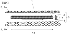
- FIG. 4 is a perspective view of the adhesive member as seen from the first adhesive resin layer;
- FIG. FIG. 4 is a perspective view of the adhesive member as seen from the second adhesive resin layer;
- 1 is a cross-sectional view of one mode of an adhesive processed product;
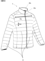
- FIG. 1 is a front view of one embodiment of an adhesive processed product;
- FIG. 4 It is a conceptual diagram which shows the aspect which formed the shape of the 1st adhesive resin layer 4a or/and the 2nd adhesive resin layer 4b in the shape of a dot.
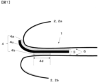
- FIG. 4 is a cross-sectional view of the adhesive member at the moment when the first adherend and the second adherend of the adhesive portion are peeled off;
- FIG. 4 is a cross-sectional view of the adhesive member in the process of peeling off the first adherend and the second adherend of the adhesive portion;
- FIG. 1 shows an overview of the cross section of the adhesive processed product of the present invention.
- 2 shows a perspective view of the adhesive member as seen from the first adhesive resin layer
- FIG. 3 shows a perspective view of the adhesive member as seen from the second adhesive resin layer.
- FIG. 4 shows a cross-sectional view of one mode of the adhesive processed product.
- the adhesive processed product 1 is composed of an adherend 2 and an adhesive member 4 .
- the adherend 2 has at least two bodies, a first adherend 2a and a second adherend 2b.
- the adhesive member 4 is composed of a substrate layer and an adhesive resin layer.
- a first adhesive resin layer 4a is arranged on one surface of the substrate layer 4c, and a second adhesive resin layer 4b is arranged on the other surface. formed by
- the first adhesive resin layer 4a of the adhesive member 4 is in contact with the first adherend 2a, and the second adhesive resin layer 4b of the adhesive member 4 is in contact with the second adherend 2b at the adhesive surface 6, respectively. .
- the elements that make up the adhesive strength of the bonded product 1 are the adhesive strength of the material itself of the adherend 2, that is, the peel strength of the first adherend 2a and the peel strength of the second adherend 2b, and the adhesive member 4 and the adhesive strength between the first adherend 2a and the second adherend 2b, that is, the peel strength of the adhesive product 1 itself.
- the adhesive strength at the interface between the adherend 2 and the adhesive member 4 facing each other will be different.
- the adhesive strength of the adhesive processed product 1 depends on the lowest adhesive strength among the adhesive strengths at the respective boundary surfaces in the previous section.
- the adhesive strength at the interface between the first adherend 2a and the first adhesive resin layer 4a is the same as that of the second adherend 2b and the second adhesive resin less than the bond strength at the interface of layer 4b. Due to this magnitude relationship of the adhesive strength, peeling occurs first at the interface between the first adherend 2a and the first adhesive resin layer 4a.
- a peeling force is applied to the adhesive portion 3 as in the adhesive processed product shown in FIG. It changes depending on the size relationship between the surface area 5a and the surface area 5b of the second adhesive resin layer.
- the force is first applied to the adhesive resin side having a small surface area in the short side direction 4d of the adhesive member and the outer edge side facing the peeling direction, Next, the same force is applied to the adhesive resin layer on the opposite side of the substrate layer 4c.
- FIG. 7 is a cross-sectional view of the adhesive member at the moment when the first adherend and the second adherend of the adhesive part are peeled off
- FIG. 2 is a cross-sectional view of the adhesive member in the process of being peeled off from the adherend.
- the surface area 5a of the first adhesive resin layer is larger than the surface area 5b of the second adhesive resin layer, so as shown in FIG.
- the first adhesive resin layer 4a and the substrate layer 4c follow the first adherend 2a, and the peeling force is the left end of the second adhesive resin layer 4b and the second adherend 2b.
- the peeling force applied to the bonded product changes depending on the magnitude relationship between the surface area 5a of the first adhesive resin layer and the surface area 5b of the second adhesive resin layer that constitute the adhesive member 4.
- the order in which the peeling force is applied can be changed and dispersed.
- the adhesive strength due to shear peeling that peels off in the same direction is higher than the adhesive strength when peeling force is applied in the 90° direction.
- the second adherend The peel strength on the adherend side affects the peel strength of the bonded article itself. Even if the shear peel strength on the first adherend side ⁇ the peel strength on the second adherend side, the shear peel strength on the first adherend side will affect the peel strength of the adhesive product itself. Become. The former is generally the case unless the difference in adhesive strength between the first adherend and the second adherend is extremely large. In any case, the peel strength of the adhesive product itself is greater than the peel strength of the first adherend. higher than strength.
- the adhesive strength between the first adherend and the first adhesive resin layer is increased even if the first adherend having a low adhesive strength is used. As a result of raising the level, the peel strength of the adhesive product 1 itself can be increased.
- the peel strength of the first adherend 2a is smaller than the peel strength of the second adherend 2b, and the surface area 5b of the second adhesive resin layer 4b in the adhesive member 4 is It is smaller than the surface area 5a of the first adhesive resin layer 4a.
- the load or peeling force applied to the adhesive processed product 1 is deflected to the second adhesive resin layer 4b, which is on the side with the higher peel strength, so that the load is distributed to the first adhesive resin layer 4a and the peeling durability is improved. can be achieved, that is, the bonding strength of the bonded product 1 is excellent.
- the peel strength of the adherend 2 here is measured based on JIS L1086 (2020) 7.10.1.
- the first adherend 2a is used as the adherend cloth
- the adherend cloth is the second adherend. 2b is used.
- the load or peeling force applied to the bonded product 1 will be biased toward the first adhesive resin layer 4a, which has a lower peel strength, so that peeling will easily occur and the adhesive strength of the bonded product 1 will be inferior.
- peel strength ratio Peel strength of first adherend 2a (N/cm)/Peel strength of second adherend 2b (N/cm)
- peel strength ratio peel strength of first adherend 2a (N/cm)/Peel strength of second adherend 2b (N/cm)
- the difference in peel strength between the first adhesive resin layer 4a and the second adhesive resin layer 4b is preferable. It is possible to sufficiently distribute and deflect the tensile load and peeling force of the first adhesive resin layer 4a, which is on the lower side of the peeling strength, and the effect of improving the bonding strength of the bonded product 1 is excellent. It is more preferably 10% or more and 60% or less.
- a difference in bulkiness or surface roughness of the surfaces of the first adherend 2a and the second adherend 2b is provided, that is, a difference in anchor effect is provided, a difference in elongation elasticity is provided, Any method may be used, such as providing different melting points and viscosities of raw materials, but from the viewpoint of versatility of specifications, it is preferable to provide different bulkiness and surface roughness.
- the ratio of the surface area 5b of the second adhesive resin layer of the adhesive member 4 to the surface area 5a of the first adhesive resin layer (hereinafter referred to as "surface area ratio”.
- the surface area is the area of the surface of the adhesive resin layer on the adhesive surface 6 side, and corresponds to the area where each adhesive resin layer adheres to each adherend.) is preferably 10% or more. , 70% or less.
- Surface area ratio [Surface area 5b (cm 2 ) of second adhesive resin layer/Surface area 5a (cm 2 ) of first adhesive resin layer] x 100 (%)
- Surface area 5a of the first adhesive resin layer the short side dimension of the first adhesive resin layer 4a in the short side direction 4d of the adhesive member 4 and the first surface area in the long side direction 4e of the adhesive member 4 shown in FIGS.
- Surface area of the second adhesive resin layer 4b The short side dimension of the second adhesive resin layer 4b in the short side direction 4d of the adhesive member 4 shown in FIGS.
- the first adhesive resin layer 4a and the second adhesive resin layer 4b have a surface area ratio of 10% or more to the long side dimension of the second adhesive resin layer 4b in the long side direction 4e of the adhesive member 4.
- the difference in surface area between the The surface area difference between the surface areas of the first adhesive resin layer 4a and the second adhesive resin layer 4b is within a preferable range, and the tensile load and peeling force of the first adhesive resin layer 4a, which is the side with the lower peel strength, is dispersed and deflected. can be sufficiently fulfilled, and the effect of improving the adhesive strength of the adhesive processed product 1 is excellent.
- a more preferable range is 30% or more and 60% or less.
- a difference is provided between the dimension of the first adhesive resin layer 4a and the dimension of the second adhesive resin layer 4b in the short side direction 4d of the adhesive member 4. or providing a difference between the dimension of the first adhesive resin layer 4a and the dimension of the second adhesive resin layer 4b in the long side direction 4e of the adhesive member 4; It is difficult to visually recognize the difference between the front and back of the adhesive processed product 1 in appearance, that is, from the viewpoint of appearance quality, the dimension of the first adhesive resin layer 4a and the dimension of the second adhesive resin layer 4b in the short side direction of the adhesive member 4 It is preferable to provide a difference between
- the shape of the first adhesive resin layer 4a and/or the second adhesive resin layer 4b of the adhesive member 4 is a dot shape in which the resins are not continuous, an intermittent shape, a zigzag shape, or a zigzag shape. It can be shaped.
- the shape of the dot is not limited to circular, polygonal, etc., but circular is preferable from the viewpoint of versatility of corresponding equipment and quality stability.
- the intermittent shape may be a plurality of straight lines or dotted lines.
- the adhesive resin intermittently exist in the direction of expansion and contraction.
- a knitted fabric or a woven fabric that stretches in both the weft and weft directions it is preferable to use a dot shape from the viewpoint of excellent followability in the stretch direction of the adherend.
- the area of the region where the adhesive resin such as the dot shape is present affects the adhesive force. It is the area of the region where the adhesive resin exists such as the shape. Specifically, a polygon or circle having the smallest number of points of contact with the adhesive resin among the smallest polygons or circles circumscribing the area where the adhesive resin such as dots exists is assumed, and the area thereof is calculated. In quilted products such as down jackets, in which stuffing such as batting and feathers is stuffed in the side fabric, when the bonding part is provided as a partition for the insertion part of the stuffing, the bonding part is often straight or curved. In this case, the area of the smallest quadrangle, such as a rectangle, which circumscribes the area where the adhesive resin is present, is assumed in the sample taken from the bonded product by the method described later, and the area thereof is calculated.
- the example shown in FIG. 6 is an embodiment in which the shape of the first adhesive resin layer 4a and/or the second adhesive resin layer 4b is formed in a dot shape.
- the dimension is the distance between the outermost edges in the short side direction 4d of the bonding member.
- the dimension in the long side direction 4e' of the adhesive resin layer is the distance between the outermost edges of the adhesive member in the long side direction 4e.
- the preferred range of the ratio of the surface area 5b of the second adhesive resin layer to the surface area 5a of the first adhesive resin layer (hereinafter referred to as “surface area ratio”) is 10% or more and 70% or less.
- the method of laminating the first adhesive resin layer 4a, the second adhesive resin layer 4b, and the base material layer 4c in the adhesive member 4 is a method of laminating together the centers of the respective short side directions 4d'. It is preferably used because it is effective against peeling from either end in the short side direction, but methods other than the above method may also be used. For example, when the peeling force is applied in one direction, peeling occurs in the short side direction 4d or the long side direction 4e of each of the first adhesive resin layer 4a, the second adhesive resin layer 4b, and the base material layer 4c.
- the end portion in the direction opposite to the direction in which the force is applied is moved to one side in the short side direction 4d of the adhesive member, and only the side to which the peeling force is applied is the two layers of the base layer 4c and the first adhesive resin layer 4a.
- the shape of the adhesive surface of the adhesive member is not limited to the shape having short and long sides as described above, and the shape can be changed as appropriate in consideration of the design of the adhesive processed product and the direction in which the peeling force is assumed to be applied. is possible.
- organic adhesives are mainly used as the type of resin that constitutes the adhesive resin layer.
- the types of organic adhesives include natural resins such as natural rubber casein, semi-synthetic adhesives such as cellulose acetate, polyurethanes, and the like. It is roughly classified into synthetic resin systems using acrylic or the like, but synthetic resin systems are preferable in terms of workability and cost.
- Synthetic resin components include resins such as polyurethane, polyester, polyvinyl alcohol, vinyl chloride, acrylic resin, polyethylene, ethylene-vinyl acetate polymer, polyamide, and polyolefin, as well as silicon rubber and nitrile rubber. It is subdivided into composite systems such as elastomer systems and nylon-epoxy and vinyl-phenolic systems. Polyurethane, acrylic, nylon, ethylene vinyl acetate, polycarbonate and olefin are more preferable because of their high processability and heat resistance and adhesive strength due to cross-linking reaction with moisture (humidity) contained in the air. , which is also excellent in durability.
- resins such as polyurethane, polyester, polyvinyl alcohol, vinyl chloride, acrylic resin, polyethylene, ethylene-vinyl acetate polymer, polyamide, and polyolefin, as well as silicon rubber and nitrile rubber. It is subdivided into composite systems such as elastomer systems and nylon-epoxy and vinyl
- Synthetic resins can be solidified by drying, such as water-soluble, latex, or dispersion types, or chemically reactive types, in which a cross-linking reaction occurs when the base resin and curing agent are mixed, and solid at room temperature but heated.
- a heat-melting type thermoplastic hot-melt
- a pressure-sensitive type that pressurizes and adheres a high-viscosity fluid liquid
- a moisture-hardening type that hardens by reacting with moisture in the air (moisture-hardening type). reactive hot melt).
- thermoplastic hot-melt thermoplastic hot-melt
- moisture-curing reactive hot-melt moisture-curing reactive hot-melt
- the resin component suitably used for the adhesive processed product of the present invention is at least one component selected from polyurethane, acrylic, nylon, ethylene vinyl acetate, polycarbonate and olefin, and a resin is at least one selected from moisture-curable reactive hot melts and thermoplastic hot melts.
- the first adhesive resin layer 4a and the second adhesive resin layer 4b of the adhesive member 4 are made of different resin components, or in the reaction mode, one resin layer is There is no problem in using a thermoplastic hot-melt layer and the other resin layer of a moisture-curable reactive hot-melt layer.
- the resin component of the first adhesive resin layer 4a is acrylic
- the reaction form is thermoplastic hot melt
- the resin component of the second adhesive resin layer 4b is polyurethane
- the reaction form is a moisture-curable reactive resin.
- the adhesive member 4 of the present invention comprises a substrate layer 4c and an adhesive resin layer.
- the first adhesive resin layer 4a is arranged on one surface of the substrate layer 4c, and the second adhesive resin It is formed by arranging the layer 4b.
- the surface area 5b of the second adhesive resin layer is smaller than the surface area 5a of the first adhesive resin layer.
- the adhesive member 4 and the adherend 2 are adhered using a hot press process or the like, if an excessive amount of heat, pressure, or time is applied, the molten first adhesive resin layer 4a will become the base layer 4c. , and adheres not only to the first adherend 2a, which is the original adhesive surface 6, but also to the opposing second adherend 2b, thereby inhibiting the adhesive strength.
- the first adhesive resin in the short side direction of the adhesive member 4 has the size of the base material in the short side direction of the adhesive member 4.
- the first adhesive resin layer 4a is applied on the base material in a size equal to or less than the base material size, or the first adhesive resin layer is applied on the base material. 4a may be applied to the entire surface and then cut to a predetermined size. A preferred method is to apply the adhesive resin layer 4a to the size of the substrate or less.
- the second adhesive resin layer can also be provided in the same manner as the first adhesive resin layer.
- the material for the base material layer 4c it is preferable to mainly use a fiber woven or knitted fabric, a nonwoven fabric, or a film alone or in a laminate because of its excellent flexibility. More preferably, it is a film or a high-density woven fabric, because the thickness is hardly visible and the quality of the appearance is excellent.
- the material is not limited, but polyester-based polyurethane resin, polyether-based polyurethane resin, polycarbonate-based polyurethane resin, acrylic resin, polyester-based resin, etc. are preferably used.
- the components constituting the adhesive resin layer are likely to melt and the components constituting the base material layer 4c are less likely to melt under heating and processing temperature conditions. It is preferable because it has excellent properties.
- the melting point temperature it is preferable that the melting point temperature T1 of the component of the base layer 4c is higher than the melting point temperature T2 of the component of the adhesive resin layer from the viewpoint of shape stability during adhesion processing.
- the melting point temperature T1 of the component of the base layer 4c is lower than the melting point temperature T2 of the component of the adhesive resin layer, the component of the base layer 4c melts first before the component of the adhesive resin layer melts during the bonding process. There is a problem that the adhesion work is hindered.
- the ratio (T 1 /T 2 ) of the melting point temperature T 1 of the component of the base material layer 4c to the melting point temperature T 2 of the component of the adhesive resin layer is in the range of 1.1 to 2.5.
- the melting point temperature was measured using a DMAQ800 manufactured by TA Instruments in a temperature rise/control force mode at a temperature rise rate of 10° C./min, and the melting point was defined as the point at which the amount of strain displacement remarkably changed.
- adherend 2 in the present invention it is preferable to mainly use any one of a fiber woven or knitted fabric, a nonwoven fabric, or a film because of the versatility and flexibility of the bonding process.
- a woven or knitted fabric is more preferable because of its excellent strength.
- plain weaves, twill weaves, satin weaves, variations of these weaves, multiaxial weaves, and the like are generally preferably used.
- knitted fabrics plain knitted fabrics, rubber knitted fabrics, pearl knitted fabrics, tricot fabrics, Raschel fabrics, Milanese fabrics, and the like are preferably used.
- a nonwoven fabric a papermaking method, a chemical adhesion method, a heat fusion method, a water jet punch method, a melt blow method, a flash spinning method, or the like is preferably used.
- synthetic fibers such as polyester, nylon, polyurethane, polypropylene, polyethylene, and acrylic, natural fibers such as cotton, and animal fibers such as wool are suitably used.
- Synthetic fibers include polyamide homopolymers such as nylon 6/6, nylon 6, nylon 12, and nylon 4/6, copolymers of nylon 6 and nylon 6/6, polyalkylene glycol, dicarboxylic acid and amine in nylon 6.
- Polyester homopolymers such as polyethylene terephthalate and polybutylene terephthalate, or aliphatic dicarboxylic acids such as isophthalic acid, 5-sodium sulfoisophthalic acid or adipic acid as an acid component.
- Polyester fibers made of polymerized copolyester, aramid fibers represented by copolymerization with paraphenylene terephthalamide and aromatic ethers, rayon fibers, polysulfone fibers and the like are preferably used.
- Such fibers may contain various additives that are commonly used to improve productivity or characteristics in the manufacturing and processing processes of raw yarn.
- heat stabilizers antioxidants, light stabilizers, smoothing agents, antistatic agents, plasticizers, thickeners, pigments, flame retardants, antibacterial agents, heat storage agents, water repellent agents, water absorbing agents, etc. may be included. can.
- adherend 2 a plurality of different materials may be used in combination according to the usage environment and purpose. For example, when the first adherend 2a is exposed to the side to be waterproofed and used in waterproof applications and environments such as rainwear and chemical protective clothing, the first adherend 2a is waterproofed. There is no problem in using a nylon circular knitted fabric for the nylon plain weave and the second adherend 2b.
- the first adherend 2a is formed by coating at least the adhesive surface 6 with a resin, and the water resistance measured based on the JIS L1092 (2020) 7.10 method A degree of 2000 mmH 2 O (19.6 kPa) or more is preferable because it ensures the waterproofness of the first adherend 2a and the bonded product 1 and facilitates increasing the bonding strength.
- the waterproofness may be poor. More preferably, it is 10,000 mmH 2 O (98.1 kPa) or more and 30,000 mmH 2 O (294.2 kPa) or less.
- the type of resin that coats the adhesive surface 6 of the first adherend 2a is not limited, but polyester-based polyurethane resin, polyether-based polyurethane resin, polycarbonate-based polyurethane resin, acrylic resin, polyester-based resin, etc. are preferable.
- a coating method or a lamination method is preferably used as a resin coating means for coating the adhesive surface 6 of the first adherend 2a.
- any method for forming a film such as a method of dry-bonding a resin to the bonding surface 6 of the adherend 2 or a method of wet-coagulation, may be used.
- dry foaming by addition of silica or foaming agent, microporosity by wet coagulation of polyurethane, unevenness by embossing roller, or the like can be used.
- the resin film may contain titanium oxide, carbon black, pigments, antioxidants, ultraviolet absorbers, light stabilizers, flame retardants, etc. as appropriate.
- the adherend 2 on the side to be waterproofed is provided with waterproofness by resin coating, and the adherends 2 are adhered to each other via the adhesive member 4. , it is possible to provide a waterproof adhesive processed product 1 that eliminates penetration of the adherend by conventional machine sewing and water intrusion paths from the penetration part.
- a heat press method, a high-frequency heating method, and an ultrasonic processing method are preferably used as a method for bonding between the adherend 2 and the bonding member 4 that constitute the bonded product 1.
- the hot press method is excellent in cost and productivity.
- the adhesive product 1 of the present invention may be used for, for example, upper and lower garments, hats, gloves, blankets, sheets, curtains, tents, sleeping bags, umbrellas, bags, and the like.
- the bonding portion 3 can be the aspect of the present invention. More preferably, the range of 50% to 100% in the bonded portion 3 in the garment is the aspect of the present invention. By setting the thickness within the above range, it is preferable because there is little peeling or breakage when wearing clothes.
- the adhesive processed product 1 of the present invention may be configured by combining sewn parts by a sewing machine.
- a sewing machine for example, in the garment shown in FIG. 5, it is possible to use a sewing machine to sew the peripheral parts except for the quilting. Also, it is possible not to use a sewn part by a sewing machine. That is, the present invention can be used as a seam for joining at least the adherends 2 together.
- the peel strength of the adherend 2 of the adhesive product 1 was measured according to JIS L1086 (2020) 7.10.1.
- the first adherend 2a is used as the cloth to be bonded in the peel strength measurement of the first adherend 2a
- the second adherend 2b is used as the cloth to be bonded in the peel strength measurement of the second adherend 2b,
- the adhesive used in this test was a urethane-based hot melt " ⁇ S23 (100 ⁇ m)" manufactured by Toray Coatex Co., Ltd., and the test piece was adhered using a hot plate press at a temperature of 140° C. for 10 seconds and a pressure of 1 kg/cm 2 . was prepared and the peel strength was measured.
- the unit is N/cm.
- Peel strength ratio [Peel strength of first adherend 2a / Peel strength of second adherend 2b] x 100 (%) [Ratio of Surface Area of Second Adhesive Resin Layer 4b to First Adhesive Resin Layer 4a]
- the surface area ratio of the second adhesive resin layer 4b and the first adhesive resin layer 4a was determined by the following formula.
- the surface area 5a of the first adhesive resin layer is the dimension of the first adhesive resin layer 4a in the short side direction of the adhesive member 4 and the first surface area in the long side direction of the adhesive member 4.
- the dimension of the adhesive resin layer 4a was measured, and the product of the dimension and each value in the short side direction was used. The unit was cm 2 .
- the surface area 5b of the second adhesive resin layer measures the dimension of the second adhesive resin layer 4b in the short side direction of the adhesive member 4 and the dimension of the second adhesive resin layer 4b in the long side direction of the adhesive member 4.
- the product of each value was used.
- the unit was cm 2 .
- the dimension in the long side direction of the adhesive member was set to 50 cm for each of the first adhesive resin layer, the second adhesive resin layer, and the base material layer, as will be described later.
- the dimension in the long side direction of the adhesive member when measuring each dimension from a bonded product, include all the lengths in the short direction, and the size that can be collected in the long direction.
- a sample having a size larger than the short side direction if it is difficult to obtain that size, a size as close to that size as possible) is cut out and collected. If the adhesive member draws a gentle curve, the portion that is as close to a straight line as possible should be cut out and collected.
- Aesthetics of the bonded product that is, the degree of visibility of contours and steps, specifically, the degree of contours of steps and edges due to the thickness and hardness of the adhesive resin layer and the base layer 4c of the bonded product 1, and adhesion
- the presence or absence of seepage of the resin layer onto the surface of the adherend, that is, the appearance quality was visually determined and evaluated according to the criteria shown in Table 1. The higher the parameter score, the better the aesthetics.
- the first adherend is a nylon taffeta fabric, that is, a 16dtex-5f nylon filament yarn for warp fibers and a weft yarn.
- a nylon taffeta fabric that is, a 16dtex-5f nylon filament yarn for warp fibers and a weft yarn.
- 33dtex-26f nylon filament yarn for the fiber after weaving a plain weave with a warp yarn density of 207 / 2.54 cm and a weft yarn density of 147 / 2.54 cm, relax scouring and circular dyeing at 130 ° C. After drying, a 180° up/60° down calendered nylon fabric was obtained.
- a nylon taffeta fabric that is, a 17 dtex-7f nylon crimped filament processed yarn having a twist number of 500 times / m and a bulk height of 6 cm 3 /g in the warp yarn fiber, and a weft yarn fiber
- a 26dtex-20f nylon crimped filament yarn was used in the above to obtain a nylon fabric finished with a warp yarn density of 250 / 2.54 cm and a weft yarn density of 164 / 2.54 cm.
- thermoplastic polyurethane hot-melt resin that is, a resin mainly composed of a polyester-based polyurethane resin having a softening point of 60° C. and a melting point of 115° C. with hot-melt adhesiveness is used and extruded.
- thermoplastic polyurethane hot-melt resin obtained by the same raw material and manufacturing method as the first resin layer was obtained as the second adhesive resin layer.
- a resin mainly composed of a polyester polyurethane resin having a softening point of 80° C. and a melting point of 150° C. is used as a raw material, and the film thickness is 50 ⁇ m and the stress at 50% elongation is 0.5 MPa, and the breaking strength is 26 MPa.
- a film was obtained by discharging and stretching in the form of a sheet.
- the first adhesive resin layer is slit-molded so that the dimension in the short side direction of the adhesive member is 1 cm
- the second adhesive resin layer is slit-molded so that it is 0.5 cm
- the base material is 1.2 cm. Molded like this.
- first adhesive resin layer, the second adhesive resin layer, and the substrate layer were all set to 50 cm in the long-side dimension of the adhesive member.
- the obtained adhesive resin layer was laminated on the substrate layer to obtain an adhesive member composed of the first adhesive resin layer, the substrate layer and the second adhesive resin layer.
- the adhesive surface on one side of the adhesive member i.e., the first adhesive resin layer
- the adhesive surface on the opposite side of the adhesive member i.e., the second adhesive resin layer
- the second adherend is placed on the second adherend. and heat-bonded using a flat plate heat press under the conditions of a temperature of 140° C., a pressure of 1 kg/cm 2 , and a time of 10 seconds to form a bonded portion to obtain a bonded product.
- Peel strength of first and second adherends, peel strength ratio of first adherend and second adherend, surface area ratio of second adhesive resin layer and first adhesive resin layer, adhesive member The dimensional ratio of the substrate and the first adhesive resin layer in the short side direction of the adhesive product and the peel strength of the adhesive portion of the obtained adhesive processed product were measured.
- Example 2 In the bonded product of Example 1, as the first adherend 2a, a nylon-coated fabric, that is, a nylon filament yarn of 33 dtex-26 f for both warp and weft fibers is used, and the warp density is 236. After weaving a taffeta fabric having a thread/2.54 cm and a weft thread density of 197 threads/2.54 cm, a polyurethane resin coating was obtained at a coating amount of 43 g/m 2 . The water resistance of the first adherend 2a measured according to JIS L1092 (2009) 7.1.2B method was 10000 mmH 2 O (98.1 kPa).
- a polyurethane-based moisture-curable reactive resin that is, a polyurethane-based resin (melting point temperature: 100°C) with a viscosity of 5,000 mPa ⁇ s (120°C) was applied using a dispenser with a nozzle diameter of 0.3 mm.
- the substrate was coated under the conditions of a syringe temperature of 120°C and a nozzle temperature of 150°C.
- the dimensions in the short side direction of the adhesive member 4 were 1.5 cm for the first adhesive resin layer 4a, 0.7 cm for the second adhesive resin layer 4b, and 1.5 cm for the base material, and the adhesive member 4 was obtained.
- a bonded product was produced under the same conditions as in Example 1 except for the structure of the adherend 2 and the bonding member 4 .
- Table 3 shows each numerical value and evaluation results.
- Example 3 In the bonded product of Example 1, as the first adherend 2a, a coated nylon circular knitted material, that is, a 75dtex-72f nylon filament yarn is used, and an interlock texture knitted fabric is formed with a 28G double-sided circular knitting machine. After knitting, relaxation/scouring, dyeing, and finishing setting were carried out to obtain a knitted fabric coated with a polyurethane resin in an application amount of 43 g/m 2 .
- the water resistance of the first adherend 2a measured according to JIS L1092 (2009) 7.1.2B method was 8000 mmH 2 O (78.5 kPa).
- a nylon circular knitted fabric that is, a 75dtex-72f nylon filament yarn is used, and an interlock texture knitted fabric is knitted with a 28G double-sided circular knitting machine, followed by relaxing, refining, dyeing, A finished knitted fabric was obtained.
- the dimensions in the short side direction of the adhesive member 4 were 2.5 cm for the first adhesive resin layer 4a, 1.5 cm for the second adhesive resin layer 4b, and 2.4 cm for the base material, and the adhesive member 4 was obtained.
- a bonded product was produced under the same conditions as in Example 1 except for the structure of the adherend 2 and the bonding member 4 .
- Table 3 shows each numerical value and evaluation results.
- Example 4 In the bonded product of Example 1, as the first adherend 2a, an olefin-based nonwoven fabric, that is, polypropylene with a fiber diameter of 3.2 ⁇ m, was used, the distance between fibers was 16.3 ⁇ m, the thickness was 0.21 mm, and the bulkiness was A spunbonded nonwoven fabric having a tensile strength of 3.5 cm 3 /g, an air permeability of 100 cm 3 /cm 2 /sec, a tensile strength of 126 N/5 cm, and a basis weight of 60 g/m 2 was calendered at an upper 80 degree/lower 60 degree. I got what I did.
- an olefin nonwoven fabric that is, polypropylene with a fiber diameter of 3.2 ⁇ m is used, the distance between fibers is 16.3 ⁇ m, the thickness is 0.21 mm, and the bulkiness is 3.5 cm 3 / g, air permeability of 100 cm 3 /cm 2 /sec, tensile strength of 126 N/5 cm, and basis weight of 60 g/m 2 .
- an olefinic thermoplastic hot-melt resin that is, a resin mainly composed of a polypropylene resin having a softening point of 60°C and a melting point temperature of 90°C with hot-melt adhesiveness. was extruded into a sheet on a release paper so as to have a thickness of 100 ⁇ m, and then the adhesive resin layer was separated from the release paper to obtain an adhesive resin layer.
- thermoplastic hot-melt resin obtained by the same raw material and manufacturing method as the first resin layer was obtained.
- the base material layer 4c an olefin-based nonwoven fabric obtained by the same raw material and manufacturing method as the first adherend 2a was used.
- the dimensions in the short side direction of the adhesive member 4 were 1.5 cm for the first adhesive resin layer 4a, 1.2 cm for the second adhesive resin layer 4b, and 1.4 cm for the base material, and the adhesive member 4 was obtained.
- a bonded product was produced under the same conditions as in Example 1 except for the structure of the adherend 2 and the bonding member 4 .
- Table 3 shows each numerical value and evaluation results.
- Example 5 In the second adhesive resin layer 4b of the adhesive processed product of Example 3, in the structure of the adhesive member, polyurethane-based moisture-curing reactive hot-melt resin, that is, having hot-melt adhesiveness, viscosity at 120°C of about 12, 000 mPa ⁇ s polyurethane-based resin (melting point temperature: 110° C.) is used, and the surface of the base material layer opposite to the first adhesive resin layer is coated from a die nozzle as shown in FIG.
- polyurethane-based moisture-curing reactive hot-melt resin that is, having hot-melt adhesiveness, viscosity at 120°C of about 12, 000 mPa ⁇ s polyurethane-based resin (melting point temperature: 110° C.) is used, and the surface of the base material layer opposite to the first adhesive resin layer is coated from a die nozzle as shown in FIG.
- dots having a diameter of 1.0 mm and a thickness of 100 ⁇ m were discharged, and continuous discharge was performed from the end of the dot at intervals of 1 mm in the short side direction 4d and the long side direction 4e of the adhesive member.
- the dimension of the adhesive resin layer in the short side direction 4d′ that is, the distance between the outermost edges of the adhesive member in the short side direction 4d is 1.5 cm
- the long side dimension 4e′ of the adhesive resin layer that is, the length of the adhesive member in the long side direction 4e is 1.5 cm.
- the distance between the outermost edges was 50 cm.
- An adhesive processed product was produced under the same conditions as in Example 3 except for the configuration of the second adhesive resin layer 4b.
- Table 3 shows each numerical value and evaluation results.
- the same nylon fabric material as the first adherend 2a in the bonded product of Example 2 is used, and a nylon coated fabric coated with a polyurethane resin at a coating amount of 14 g / m 2 is used. used.
- the first adhesive resin layer 4a was 1.5 cm long
- the second adhesive resin layer 4b was 2 cm long
- the base material was 1.5 cm long.
- a bonded product was produced under the same conditions as in Example 1 except for the structure of the adherend 2 and the bonding member 4 .
- Table 3 shows each numerical value and evaluation results.
- Example 2 In the bonded product of Example 3, the second adherend 2b in Example 3, ie, a nylon circular knitted fabric, was used as the first adherend 2a. As the second adherend 2b, the first adherend 2a in Example 3, that is, the coated nylon circular knitted fabric was used.
- the second adhesive resin layer 4b and the base material layer 4c were not used, and the adhesive member 4 was composed only of the first adhesive resin layer 4a, that is, the polyurethane-based thermoplastic hot-melt resin.
- the adhesive member 4 was obtained with the first adhesive resin layer 4a having a dimension of 5 cm in the short side direction of the adhesive member 4.
- a bonded product was produced under the same conditions as in Example 1, except for the structures of the adherend 2 and the bonding member 4 described above. Table 3 shows each numerical value and evaluation results.
- the same material as the first adherend 2a was used as the second adherend 2b.
- an epoxy hot-melt resin that is, a softening point of 180° C., a melt viscosity of 250 (150° C., ICI viscometer mPa ⁇ s), and solvent solubility ( MEK 70%) resin was used.
- the adhesive member 4 was composed only of the first adhesive resin layer 4a without using the second adhesive resin layer 4b and the base material layer 4c.
- the adhesive member 4 was obtained with the first adhesive resin layer 4a having a dimension of 5 cm in the short side direction of the adhesive member 4.
- a bonded product was produced under the same conditions as in Example 1 except for the structure of the adherend 2 and the bonding member 4 .
- Table 3 shows each numerical value and evaluation results.
- Comparative Example 4 In the bonded product of Comparative Example 1, a nylon double fabric having a fineness of 70 dtex was used for the base material layer 4c, a double-woven fabric connection part was arranged in the center of the short side direction 4d of the adhesive member, and the long side of the adhesive member was It was continued in the direction 4e, and this was obtained as the base material layer 4c.
- the first adhesive resin layer 4a is arranged on one of the outermost surfaces of the obtained base material layer 4c, and the second adhesive resin layer 4b is arranged on the opposite outermost surface. , the first adhesive resin layer, the second adhesive resin layer and the substrate layer 4c were slit-molded so as to each have a length of 1.5 cm, and an adhesive member 4 was obtained.
- a bonded product was produced under the same conditions as in Comparative Example 1 except for the above configuration. Table 3 shows each numerical value and evaluation results.
- the peel strength of the first adherend 2a is lower than the peel strength of the second adherend 2b, and the surface area 5b of the second adhesive resin layer is small with respect to the surface area 5a of the first adhesive resin layer, an adhesive product having excellent adhesive stability is obtained.
- the adhesive processed products of Examples 1 to 3 further have excellent adhesion stability by setting the ratio of the surface area 5a between the second adhesive resin layer 4b and the first adhesive resin layer to a preferable range. Ta.
- the adhesive processed products of Examples 1 and 2 show the peel strength ratio between the first adherend 2a and the second adherend 2b, and the base material and the first adhesive resin layer 4a in the short side direction of the adhesive member 4.
- a bonded product having more excellent bonding stability and aesthetics was obtained.
- the surface area 5b of the second adhesive resin layer is made larger than the surface area 5a of the first adhesive resin layer, so that the substrate layer 4c and the second adhesive resin are separated at the time of separation. Stress was concentrated on the interface with the layer 4b, resulting in a bonded product with poor bonding stability.
- the peel strength of the first adherend 2a and the peel strength of the second adherend 2b are equivalent, and in the adhesive member 4, only the first adhesive resin layer 4a, that is, a single layer When the adhesive layer was used, the stress dispersion did not work at the time of peeling, and the adhesive processed product was inferior in adhesive stability due to breakage of the resin itself.
- the adhesive processed product of Comparative Example 3 is different from the preferred embodiment in the material of the adherend 2 and the components of the adhesive resin layer, so that the peel strength of the adherend 2 itself is improved. Due to the lowness and curing of the adhesive resin layer, the adhesive processed product was inferior in adhesive stability and aesthetics.
- the surface area 5b of the second adhesive resin layer and the surface area 5a of the first adhesive resin layer are the same area and the short side dimension is the same as that of the base material layer 4c.
- stress was concentrated on the interface between the base material layer 4c and the second adhesive resin layer 4b, and the thickness of the base material layer caused hardening of the texture, resulting in a bonded product with poor adhesion stability and aesthetics. .
- the present invention can be used as an adhesive processed product that is excellent in adhesive strength, aesthetics and productivity.
- Adhesive member 4a First adhesive resin layer 4b: Second adhesive resin layer 4c: base material layer 4d: short side direction 4d' of adhesive member: short side direction 4e of adhesive resin layer: long side direction 4e' of adhesive member: long side direction 5a of adhesive resin layer: first adhesive resin layer
- Surface area 5b surface area of second adhesive resin layer 6: adhesive surface
Abstract
In order to provide a bonded article that has excellent bonding strength, can combine adherends of different configurations, and also has excellent productivity, this bonded article comprises at least a first adherend, a second adherend, and a bonding member interposed between the first adherend and the second adherend, the bonded article being characterized in that: the bonding member includes at least a first bonding resin layer, a second bonding resin layer, and a base material layer interposed between the first bonding resin layer and the second bonding resin layer; the first bonding resin layer contacts the first adherend; the second bonding resin layer contacts the second adherend; the peeling strength of the first adherend measured on the basis of JIS L 1086(2020)7.10 is lower than the peeling strength of the second adherend; and the surface area of the second bonding resin layer is less than the surface area of the first bonding resin layer.
Description
本発明は、接着加工品に関する。
The present invention relates to an adhesive processed product.
従来から、繊維被着体をミシン縫製することなく接着させた接着加工品は種々市販されている。これらの接着手法としては、重ね合わされた被着体同士の中間に接着剤を介在させて接着する接着手法や、重ね合わされた被着体同士を溶融・固化させて溶着する接着手法が用いられている。
Conventionally, there are various types of bonded products on the market that are made by bonding fiber adherends without sewing. As these adhesion methods, an adhesion method in which an adhesive is interposed between the superimposed adherends and an adhesion method in which the superimposed adherends are melted and solidified and welded are used. there is
特許文献における接着加工品としては、重ね合わせた被着体と被着体の間にウレタン系、アクリル系、シリコン系などの樹脂を接着剤とした熱接着テープを挿入し、加熱圧着することにより熱接着テープの接着剤を溶融・固化させて被着体同士を接着させた繊維製品が知られている(特許文献1、2)。しかし、接着剤を用いたこれまでの接着は、接着部の引っ張りや繰り返し洗濯を行った際に接着部のはく離、すなわち剥がれが生じやすく、ミシン縫製同等の強度を確保することが困難であった。
As the adhesive processed product in the patent document, a thermal adhesive tape with a resin such as urethane, acrylic, or silicon as an adhesive is inserted between the adherends that are superimposed, and the tape is heat-pressed. A textile product is known in which adherends are bonded together by melting and solidifying the adhesive of a thermal adhesive tape (Patent Documents 1 and 2). However, with conventional adhesive bonding, when the adhesive is pulled or washed repeatedly, the adhesive tends to peel off, making it difficult to ensure the same level of strength as sewing by a sewing machine. .
この改善として、片側の面に接着樹脂からなるドット状の接着部が備えられた取付布を用い、該取付布の接着部が備えられていない面同士が対向するように配置し、長手方向にそろえて接合することで、表素材への追従性を与え、接着部への引張応力を分散させた技術(特許文献3)が開示されている。
In order to improve this, a mounting cloth provided with dot-shaped adhesive portions made of adhesive resin on one side is used, and the surfaces of the mounting cloth that are not provided with adhesive portions are arranged so as to face each other, and are arranged in the longitudinal direction. A technology (Patent Literature 3) is disclosed in which, by aligning and joining, the followability to the surface material is imparted and the tensile stress applied to the joint is dispersed.
しかしながら、特許文献3の片側の面にドット状の接着樹脂部を備えた取付布および接着部が備えられていない面同士が対向するように配置され、長手方向をそろえて接合したものは、製造工程において塗布後の取付布を接着面数分準備する工程と、塗布後の取付布同士を接合させる工程、被着体と接合させる工程とをそれぞれ必要とし、生産性に劣るうえ、接着部において相対する取付布同士の積層による厚みが風合硬化を招きやすいという問題があった。
However, the mounting cloth having the dot-shaped adhesive resin part on one side of Patent Document 3 and the side not provided with the adhesive part are arranged so as to face each other, and are joined together in the longitudinal direction. In the process, the process of preparing the mounting cloth after application for the number of bonding surfaces, the process of bonding the mounting cloth after application, and the process of bonding to the adherend are required, respectively. There is a problem that the thickness due to the lamination of the facing mounting cloths tends to cause hardening of the feel.
このように従来の接着加工品は、いずれも接着部の接着強度、生産性、風合において十分な性能を満足しうるものではなかった。
In this way, none of the conventional adhesive processed products were able to satisfy sufficient performance in terms of adhesive strength, productivity, and texture of the adhesive part.
そこで、本発明の目的は上記従来の問題を解消することを課題とし、
接着強度に優れ、かつ構成の異なる被着体を組み合わせることができ、生産性にも優れた接着加工品を提供することにある。 Therefore, the object of the present invention is to solve the above conventional problems,
To provide an adhesive processed product excellent in adhesive strength, capable of combining adherends having different constitutions, and excellent in productivity.
前記課題を解決するため、本発明の接着加工品は、以下の構成からなる。
In order to solve the above problems, the adhesive processed product of the present invention has the following configuration.
(1)少なくとも第一の被着体と、第二の被着体と、第一の被着体と第二の被着体との間に接着部材が介在してなる接着加工品であって、
前記接着部材は、少なくとも第一の接着樹脂層と、第二の接着樹脂層と、第一の接着樹脂層と、第二の接着樹脂層との間に介在する基材層とからなり、
前記第一の接着樹脂層は前記第一の被着体と接し、前記第二の接着樹脂層は前記第二の被着体と接し、JIS L1086(2020)7.10に基づき測定した前記第一の被着体の剥離強度が、第二の被着体の剥離強度より低く、前記第二の接着樹脂層の表面積は、前記第一の接着樹脂層の表面積より小さいことを特徴とする、接着加工品。
(2)前記第二の接着樹脂層の表面積の第一の接着樹脂層の表面積に対する比率が10%以上、70%以下であることを特徴とする上記(1)に記載の接着加工品。
(3)前記第一の被着体および前記第二の被着体は、JIS L1086(2020)7.10に基づき測定した前記第二の被着体の剥離強度に対する第一の被着体の剥離強度の比率が5%以上、90%以下であることを特徴とする上記(1)又は(2)に記載の接着加工品。
(4)前記第一の被着体および前記第二の被着体は、少なくとも繊維織編物、不織布およびフィルムから選ばれることを特徴とする上記(1)~(3)のいずれかに記載の接着加工品。
(5)前記接着部材の短辺方向における基材層の寸法の、第一の接着樹脂層の寸法に対する比率が100%以上、150%以下であることを特徴とする上記(1)~(4)のいずれかに記載の接着加工品。 (1) An adhesive processed product comprising at least a first adherend, a second adherend, and an adhesive member interposed between the first adherend and the second adherend ,
The adhesive member comprises at least a first adhesive resin layer, a second adhesive resin layer, and a substrate layer interposed between the first adhesive resin layer and the second adhesive resin layer,
The first adhesive resin layer is in contact with the first adherend, the second adhesive resin layer is in contact with the second adherend, and the second measured based on JIS L1086 (2020) 7.10 The peel strength of one adherend is lower than the peel strength of the second adherend, and the surface area of the second adhesive resin layer is smaller than the surface area of the first adhesive resin layer. Adhesive products.
(2) The bonded product according to (1) above, wherein the ratio of the surface area of the second adhesive resin layer to the surface area of the first adhesive resin layer is 10% or more and 70% or less.
(3) The first adherend and the second adherend are the peel strength of the second adherend measured based on JIS L1086 (2020) 7.10. The adhesive product according to (1) or (2) above, wherein the peel strength ratio is 5% or more and 90% or less.
(4) The first adherend and the second adherend according to any one of (1) to (3) above, characterized in that they are selected from at least fiber woven and knitted fabrics, nonwoven fabrics and films. Adhesive products.
(5) The above (1) to (4), wherein the ratio of the dimension of the base layer in the short side direction of the adhesive member to the dimension of the first adhesive resin layer is 100% or more and 150% or less. ).
本発明によれば、接着強度に優れ、かつ生産性にも優れた接着加工品を得ることができる。
According to the present invention, it is possible to obtain an adhesive processed product with excellent adhesive strength and excellent productivity.
以下、図面を用いて本発明の接着加工品を詳細に説明する。
The bonded processed product of the present invention will be described in detail below with reference to the drawings.
<接着加工品の構成>
本発明の接着加工品断面の概要を図1に示す。また、接着部材の第一の接着樹脂層から見た斜視図を図2に示し、接着部材の第二の接着樹脂層から見た斜視図を図3に示す。接着加工品の一態様の断面図を図4に示す。 <Structure of bonded product>
FIG. 1 shows an overview of the cross section of the adhesive processed product of the present invention. 2 shows a perspective view of the adhesive member as seen from the first adhesive resin layer, and FIG. 3 shows a perspective view of the adhesive member as seen from the second adhesive resin layer. FIG. 4 shows a cross-sectional view of one mode of the adhesive processed product.
接着加工品1は、被着体2と接着部材4とから構成される。
The adhesive processed product 1 is composed of an adherend 2 and an adhesive member 4 .
被着体2は、少なくとも第一の被着体2aと、第二の被着体2bとの二体を有する。
The adherend 2 has at least two bodies, a first adherend 2a and a second adherend 2b.
接着部材4は、基材層と接着樹脂層とからなり、基材層4cの一方の面に第一の接着樹脂層4aを配し、もう一方の面に第二の接着樹脂層4bを配して形成される。
The adhesive member 4 is composed of a substrate layer and an adhesive resin layer. A first adhesive resin layer 4a is arranged on one surface of the substrate layer 4c, and a second adhesive resin layer 4b is arranged on the other surface. formed by
接着部材4の第一の接着樹脂層4aは前記第一の被着体2aと、接着部材4の第二の接着樹脂層4bは前記第二の被着体2bと、それぞれ接着面6において接する。
The first adhesive resin layer 4a of the adhesive member 4 is in contact with the first adherend 2a, and the second adhesive resin layer 4b of the adhesive member 4 is in contact with the second adherend 2b at the adhesive surface 6, respectively. .
<接着のメカニズム>
本発明の接着加工品において接着強度に優れるメカニズムは定かではないが、以下のように推定される。 <Adhesion Mechanism>
Although the mechanism by which the adhesive processed product of the present invention exhibits excellent adhesive strength is not clear, it is presumed as follows.
本発明の接着加工品において接着強度に優れるメカニズムは定かではないが、以下のように推定される。 <Adhesion Mechanism>
Although the mechanism by which the adhesive processed product of the present invention exhibits excellent adhesive strength is not clear, it is presumed as follows.
接着加工品1の接着強度を構成する要素は、被着体2の素材自身の接着強度、すなわち第一の被着体2aの剥離強度および第二の被着体2bの剥離強度と、接着部材4と第一の被着体2aおよび第二の被着体2bとの接着強度すなわち接着加工品1そのものの剥離強度との2要素に分けられる。
The elements that make up the adhesive strength of the bonded product 1 are the adhesive strength of the material itself of the adherend 2, that is, the peel strength of the first adherend 2a and the peel strength of the second adherend 2b, and the adhesive member 4 and the adhesive strength between the first adherend 2a and the second adherend 2b, that is, the peel strength of the adhesive product 1 itself.
被着体2において、第一の被着体2aと第二の被着体2bとがそれぞれ異なる素材や形状である場合、それぞれの被着体2と相対する接着部材4の境界面における接着強度は異なるものとなる。接着加工品1の接着強度は、前項それぞれの境界面における接着強度のうち、最も低い強度に左右される。
In the adherend 2, when the first adherend 2a and the second adherend 2b are made of different materials and shapes, the adhesive strength at the interface between the adherend 2 and the adhesive member 4 facing each other will be different. The adhesive strength of the adhesive processed product 1 depends on the lowest adhesive strength among the adhesive strengths at the respective boundary surfaces in the previous section.
例えば、前記第一の被着体2aの剥離強度が、第二の被着体2bの剥離強度に対して低く、かつ接着部材4の樹脂層が単一すなわち単層である場合、接着加工品1に対して引張力あるいは剥離力を加えた際、第一の被着体2aと第一の接着樹脂層4aの境界面における接着強度は、第二の被着体2bと第二の接着樹脂層4bの境界面における接着強度より低い。この接着強度の大小関係により、第一の被着体2aと第一の接着樹脂層4aの境界面において、先に剥離が生じるものとなる。
For example, when the peel strength of the first adherend 2a is lower than the peel strength of the second adherend 2b, and the resin layer of the adhesive member 4 is a single layer, that is, a single layer, the adhesive processed product 1, the adhesive strength at the interface between the first adherend 2a and the first adhesive resin layer 4a is the same as that of the second adherend 2b and the second adhesive resin less than the bond strength at the interface of layer 4b. Due to this magnitude relationship of the adhesive strength, peeling occurs first at the interface between the first adherend 2a and the first adhesive resin layer 4a.
例えば図1に示される接着加工品のように接着部3において、剥離の力が加わった際に、接着部材4内部の力が加わる順番は、接着部材4を構成する第一の接着樹脂層の表面積5aおよび第二の接着樹脂層の表面積5bの大小関係によって変化する。例えば、接着部材の短辺方向4dに向かって剥離の力が加わった場合、接着部材の短辺方向4dの表面積が小さい接着樹脂側かつ剥離方向と向かい合う外縁部側に、最初に力が加わり、次いで、基材層4cを境に相対する反対側の接着樹脂層に同様の力が加わる順番となる。
For example, when a peeling force is applied to the adhesive portion 3 as in the adhesive processed product shown in FIG. It changes depending on the size relationship between the surface area 5a and the surface area 5b of the second adhesive resin layer. For example, when a peeling force is applied in the short side direction 4d of the adhesive member, the force is first applied to the adhesive resin side having a small surface area in the short side direction 4d of the adhesive member and the outer edge side facing the peeling direction, Next, the same force is applied to the adhesive resin layer on the opposite side of the substrate layer 4c.
以下接着部材4が第一の接着樹脂層と、第二の接着樹脂層と、第一の接着樹脂層と、第二の接着樹脂層との間に介在する基材層を有する場合の剥離挙動を、図4に示す接着加工品1を例にとり考察する。図4に対して左側から第一の被着体2aと第二の被着体2bを剥離するように剥離の力が加わった場合、接着部材の短辺方向4dの左方向に剥離の力が加わることになる。この点について、さらに図7、図8も用いて説明する。図7は、接着部の第一の被着体と第二の被着体とを引き剥がす瞬間における、接着部材の断面図であり、図8は接着部の第一の被着体と第二の被着体とが引き剥がされる最中における、接着部材の断面図である。
Below, the peeling behavior when the adhesive member 4 has a first adhesive resin layer, a second adhesive resin layer, and a substrate layer interposed between the first adhesive resin layer and the second adhesive resin layer will be considered by taking the bonded product 1 shown in FIG. 4 as an example. When a peeling force is applied from the left side of FIG. 4 so as to peel the first adherend 2a and the second adherend 2b, the peeling force is applied to the left in the short side direction 4d of the adhesive member. will join. This point will be further described with reference to FIGS. 7 and 8. FIG. FIG. 7 is a cross-sectional view of the adhesive member at the moment when the first adherend and the second adherend of the adhesive part are peeled off, and FIG. 2 is a cross-sectional view of the adhesive member in the process of being peeled off from the adherend. FIG.
第一の被着体2aと第二の被着体2bが引き剥がされると、第一の接着樹脂層の表面積5aが第二の接着樹脂層の表面積5bよりも大きいので、図7に示すように、第一の接着樹脂層4aおよび基材層4cは第一の被着体2aに追従し、剥離の力は、第二の接着樹脂層4bの左端部と第二の被着体2bとの間へ加わる。
When the first adherend 2a and the second adherend 2b are separated, the surface area 5a of the first adhesive resin layer is larger than the surface area 5b of the second adhesive resin layer, so as shown in FIG. In addition, the first adhesive resin layer 4a and the substrate layer 4c follow the first adherend 2a, and the peeling force is the left end of the second adhesive resin layer 4b and the second adherend 2b. join between
本状態において、第一の接着樹脂層4aの左端近傍では、第一の接着樹脂層4aと第一の被着体2aとが、同方向にずれるように剥離するように力が加わる、いわゆるせん断剥離の状態となり、せん断抵抗が加わることにより剥離への抵抗が増加する。
In this state, in the vicinity of the left end of the first adhesive resin layer 4a, a force is applied so that the first adhesive resin layer 4a and the first adherend 2a are detached so as to be displaced in the same direction. Delamination occurs, and resistance to delamination increases due to the addition of shear resistance.
さらに第一の被着体2aと第二の被着体2bに剥離の力を加えると、接着部材4は、図8に示すように、第二の接着樹脂層4bの左端部と第二の被着体2bとの間で剥離が生じる。
Further, when a peeling force is applied to the first adherend 2a and the second adherend 2b, the adhesive member 4, as shown in FIG. Peeling occurs between the adherend 2b.
すなわち、第一の接着樹脂層4aの左端近傍では、第一の接着樹脂層4aと第一の被着体2aとが、同方向にずれるように剥離するように力が加わる、いわゆるせん断剥離の状態となる。一方、第二の被着体2b側では第二の接着樹脂層4bの左端部付近に剥離の力が加わり、第二の被着体2bの左側が接着部材4と離れるように剥離の力が加わる。
That is, in the vicinity of the left end of the first adhesive resin layer 4a, a force is applied so that the first adhesive resin layer 4a and the first adherend 2a are detached so as to be displaced in the same direction. state. On the other hand, on the side of the second adherend 2b, a peeling force is applied near the left end of the second adhesive resin layer 4b, and the peeling force is applied so that the left side of the second adherend 2b separates from the adhesive member 4. Join.
このように、接着加工品に加わる剥離による力は、接着部材4を構成する第一の接着樹脂層の表面積5aおよび第二の接着樹脂層の表面積5bの大小関係によって変化する。前記大小関係を調整することで、剥離の力が加わる順番を変化させ、分散させることが可能となる。
Thus, the peeling force applied to the bonded product changes depending on the magnitude relationship between the surface area 5a of the first adhesive resin layer and the surface area 5b of the second adhesive resin layer that constitute the adhesive member 4. By adjusting the magnitude relationship, the order in which the peeling force is applied can be changed and dispersed.
また、同じ被着体、接着樹脂層を用いた場合、同方向にずれるように剥離するせん断剥離による接着力は、90°方向に剥離力を加える場合の接着力よりも高くなる。
In addition, when the same adherend and adhesive resin layer are used, the adhesive strength due to shear peeling that peels off in the same direction is higher than the adhesive strength when peeling force is applied in the 90° direction.
これらを踏まえ本発明の接着加工品の接着強度を構成する要素を鑑みると、第一の被着体側のせん断剥離強度>第二の被着体側の剥離強度である場合には、第二の被着体側の剥離強度が、接着加工品そのものの剥離強度に影響を及ぼすことになる。仮に第一の被着体側のせん断剥離強度<第二の被着体側の剥離強度であったとしても第一の被着体側のせん断剥離強度が接着加工品そのものの剥離強度に影響を及ぼす結果となる。第一の被着体と第二の被着体の接着強度の差が極端に大きくない限り、前者の場合が一般的である。いずれにしても第一の被着体の剥離強度よりは大きくなるので、本発明の接着加工品そのものの接着強度は、前記接着部材4の樹脂層が単層である場合の接着加工品の接着強度に比較して高くなる。
Based on these, in view of the elements constituting the adhesive strength of the adhesive processed product of the present invention, if the shear peel strength on the first adherend side>the peel strength on the second adherend side, the second adherend The peel strength on the adherend side affects the peel strength of the bonded article itself. Even if the shear peel strength on the first adherend side < the peel strength on the second adherend side, the shear peel strength on the first adherend side will affect the peel strength of the adhesive product itself. Become. The former is generally the case unless the difference in adhesive strength between the first adherend and the second adherend is extremely large. In any case, the peel strength of the adhesive product itself is greater than the peel strength of the first adherend. higher than strength.
このように本発明においては、上記接着部材4を使用することにより、接着強度の小さい第一の被着体を用いても、第一の被着体と第一の接着樹脂層間の接着強度が底上げされる結果、接着加工品1そのものの剥離強度を高めることができるのである。
As described above, in the present invention, by using the adhesive member 4, the adhesive strength between the first adherend and the first adhesive resin layer is increased even if the first adherend having a low adhesive strength is used. As a result of raising the level, the peel strength of the adhesive product 1 itself can be increased.
<接着加工品1の好ましい形態>
本発明においては、第一の被着体2aの剥離強度は、第二の被着体2bの剥離強度に対して小さく、かつ、接着部材4における第二の接着樹脂層4bの表面積5bは、第一の接着樹脂層4aの表面積5aに対して小さい。これにより、接着加工品1にかかる荷重または剥離力が、剥離強度が高い側である第二の接着樹脂層4bに偏向され、第一の接着樹脂層4aへの荷重分散と剥離耐久性の向上を図ることができる、すなわち接着加工品1の接着強度に優れることになる。 <Preferred Form ofBonded Product 1>
In the present invention, the peel strength of thefirst adherend 2a is smaller than the peel strength of the second adherend 2b, and the surface area 5b of the second adhesive resin layer 4b in the adhesive member 4 is It is smaller than the surface area 5a of the first adhesive resin layer 4a. As a result, the load or peeling force applied to the adhesive processed product 1 is deflected to the second adhesive resin layer 4b, which is on the side with the higher peel strength, so that the load is distributed to the first adhesive resin layer 4a and the peeling durability is improved. can be achieved, that is, the bonding strength of the bonded product 1 is excellent.
本発明においては、第一の被着体2aの剥離強度は、第二の被着体2bの剥離強度に対して小さく、かつ、接着部材4における第二の接着樹脂層4bの表面積5bは、第一の接着樹脂層4aの表面積5aに対して小さい。これにより、接着加工品1にかかる荷重または剥離力が、剥離強度が高い側である第二の接着樹脂層4bに偏向され、第一の接着樹脂層4aへの荷重分散と剥離耐久性の向上を図ることができる、すなわち接着加工品1の接着強度に優れることになる。 <Preferred Form of
In the present invention, the peel strength of the
ここでいう、被着体2の剥離強度とは、JIS L1086(2020)7.10.1に基づき測定したものである。第一の被着体2aの剥離強度測定において、被接着布は第一の被着体2aを用い、第二の被着体2bの剥離強度測定において、被接着布は第二の被着体2bを用いる。
The peel strength of the adherend 2 here is measured based on JIS L1086 (2020) 7.10.1. In the peel strength measurement of the first adherend 2a, the first adherend 2a is used as the adherend cloth, and in the peel strength measurement of the second adherend 2b, the adherend cloth is the second adherend. 2b is used.
第一の被着体2aと第二の被着体2bの剥離強度の大小が逆である場合、あるいは、第一の接着樹脂層の表面積5aと第二の接着樹脂層の表面積5bの大小関係が逆であると、接着加工品1にかかる荷重または剥離力が、剥離強度が低い側である第一の接着樹脂層4aに偏向し、剥離が生じやすく接着加工品1の接着強度に劣る。
When the magnitude of the peel strength of the first adherend 2a and the second adherend 2b is opposite, or the magnitude relationship between the surface area 5a of the first adhesive resin layer and the surface area 5b of the second adhesive resin layer If it is reversed, the load or peeling force applied to the bonded product 1 will be biased toward the first adhesive resin layer 4a, which has a lower peel strength, so that peeling will easily occur and the adhesive strength of the bonded product 1 will be inferior.
第一の被着体2aの剥離強度の第二の被着体2bの剥離強度に対する比率(以下、「剥離強度比率」という)の好適な範囲は、5%以上、90%以下である。
剥離強度比率=第一の被着体2aの剥離強度(N/cm)÷第二の被着体2bの剥離強度(N/cm)
剥離強度比率が5%以上であることで、第一の接着樹脂層4aと第二の接着樹脂層4bとの剥離強度差が好ましい範囲となり、第一の接着樹脂層4aに引張荷重または剥離力が残留しにくく、接着加工品1の接着強度の向上効果に特に優れ、反対に90%以下であることで、第一の接着樹脂層4aと第二の接着樹脂層4bの剥離強度差が好ましい範囲となり、剥離強度が低い側である第一の接着樹脂層4aの引張荷重や剥離力の分散と偏向を十分に果たすことができ、接着加工品1の接着強度向上効果に優れる。より好適には10%以上、60%以下である。 A preferable range of the ratio of the peel strength of thefirst adherend 2a to the peel strength of the second adherend 2b (hereinafter referred to as "peel strength ratio") is 5% or more and 90% or less.
Peel strength ratio = Peel strength offirst adherend 2a (N/cm)/Peel strength of second adherend 2b (N/cm)
When the peel strength ratio is 5% or more, the difference in peel strength between the firstadhesive resin layer 4a and the second adhesive resin layer 4b is within a preferable range, and the tensile load or peel force is applied to the first adhesive resin layer 4a. is less likely to remain, and is particularly excellent in improving the adhesive strength of the adhesive processed product 1. On the contrary, when it is 90% or less, the difference in peel strength between the first adhesive resin layer 4a and the second adhesive resin layer 4b is preferable. It is possible to sufficiently distribute and deflect the tensile load and peeling force of the first adhesive resin layer 4a, which is on the lower side of the peeling strength, and the effect of improving the bonding strength of the bonded product 1 is excellent. It is more preferably 10% or more and 60% or less.
剥離強度比率=第一の被着体2aの剥離強度(N/cm)÷第二の被着体2bの剥離強度(N/cm)
剥離強度比率が5%以上であることで、第一の接着樹脂層4aと第二の接着樹脂層4bとの剥離強度差が好ましい範囲となり、第一の接着樹脂層4aに引張荷重または剥離力が残留しにくく、接着加工品1の接着強度の向上効果に特に優れ、反対に90%以下であることで、第一の接着樹脂層4aと第二の接着樹脂層4bの剥離強度差が好ましい範囲となり、剥離強度が低い側である第一の接着樹脂層4aの引張荷重や剥離力の分散と偏向を十分に果たすことができ、接着加工品1の接着強度向上効果に優れる。より好適には10%以上、60%以下である。 A preferable range of the ratio of the peel strength of the
Peel strength ratio = Peel strength of
When the peel strength ratio is 5% or more, the difference in peel strength between the first
剥離強度に差を設ける手段としては、第一の被着体2a、第二の被着体2b表面のかさ高性あるいは表面粗さの差すなわちアンカー効果の差を設ける、伸長弾性差を設ける、原料の融点や粘性に差を設けるなど、どのような方法であってもよいが、仕様汎用性の点から、かさ高性および表面粗さに差を設けることが好ましい。
As a means for providing a difference in peel strength, a difference in bulkiness or surface roughness of the surfaces of the first adherend 2a and the second adherend 2b is provided, that is, a difference in anchor effect is provided, a difference in elongation elasticity is provided, Any method may be used, such as providing different melting points and viscosities of raw materials, but from the viewpoint of versatility of specifications, it is preferable to provide different bulkiness and surface roughness.
本発明における接着加工品1のより好ましい形態として、接着部材4の第二の接着樹脂層の表面積5bの第一の接着樹脂層の表面積5aに対する比率(以下、「表面積比率」という。なおここでいう表面積とは、接着樹脂層の接着面6側における表面の面積であり、各接着樹脂層が各被着体と接着する面積に相当するものである。)の好適な範囲は、10%以上、70%以下である。
表面積比率=[第二の接着樹脂層の表面積5b(cm2)÷第一の接着樹脂層の表面積5a(cm2)]×100(%)
第一の接着樹脂層の表面積5a:図2および3に示す、接着部材4の短辺方向4dにおける第一の接着樹脂層4aの短辺寸法と、接着部材4の長辺方向4eにおける第一の接着樹脂層4aの長辺寸法との積
第二の接着樹脂層4bの表面積:図2および3に示す、接着部材4の短辺方向4dにおける第二の接着樹脂層4bの短辺寸法と、接着部材4の長辺方向4eにおける第二の接着樹脂層4bの長辺寸法との積
表面積比率が10%以上であることで、第一の接着樹脂層4aと第二の接着樹脂層4bとの表面積差が好ましい範囲となり、第二の接着樹脂層4bの引張荷重または剥離力を分散しやすく接着加工品1の接着強度の向上効果に特に優れ、反対に70%以下であることで、第一の接着樹脂層4aと第二の接着樹脂層4bの表面積との表面積差が好ましい範囲となり、剥離強度が低い側である第一の接着樹脂層4aの引張荷重や剥離力の分散と偏向を十分に果たすことができ、接着加工品1の接着強度向上効果に優れる。より好適には30%以上、60%以下の範囲である。 As a more preferable form of the adhesive processedproduct 1 in the present invention, the ratio of the surface area 5b of the second adhesive resin layer of the adhesive member 4 to the surface area 5a of the first adhesive resin layer (hereinafter referred to as "surface area ratio". The surface area is the area of the surface of the adhesive resin layer on the adhesive surface 6 side, and corresponds to the area where each adhesive resin layer adheres to each adherend.) is preferably 10% or more. , 70% or less.
Surface area ratio = [Surface area 5b (cm 2 ) of second adhesive resin layer/Surface area 5a (cm 2 ) of first adhesive resin layer] x 100 (%)
Surface area 5a of the first adhesive resin layer: the short side dimension of the first adhesive resin layer 4a in the short side direction 4d of the adhesive member 4 and the first surface area in the long side direction 4e of the adhesive member 4 shown in FIGS. Surface area of the second adhesive resin layer 4b: The short side dimension of the second adhesive resin layer 4b in the short side direction 4d of the adhesive member 4 shown in FIGS. The first adhesive resin layer 4a and the second adhesive resin layer 4b have a surface area ratio of 10% or more to the long side dimension of the second adhesive resin layer 4b in the long side direction 4e of the adhesive member 4. The difference in surface area between the The surface area difference between the surface areas of the first adhesive resin layer 4a and the second adhesive resin layer 4b is within a preferable range, and the tensile load and peeling force of the first adhesive resin layer 4a, which is the side with the lower peel strength, is dispersed and deflected. can be sufficiently fulfilled, and the effect of improving the adhesive strength of the adhesive processed product 1 is excellent. A more preferable range is 30% or more and 60% or less.
表面積比率=[第二の接着樹脂層の表面積5b(cm2)÷第一の接着樹脂層の表面積5a(cm2)]×100(%)
第一の接着樹脂層の表面積5a:図2および3に示す、接着部材4の短辺方向4dにおける第一の接着樹脂層4aの短辺寸法と、接着部材4の長辺方向4eにおける第一の接着樹脂層4aの長辺寸法との積
第二の接着樹脂層4bの表面積:図2および3に示す、接着部材4の短辺方向4dにおける第二の接着樹脂層4bの短辺寸法と、接着部材4の長辺方向4eにおける第二の接着樹脂層4bの長辺寸法との積
表面積比率が10%以上であることで、第一の接着樹脂層4aと第二の接着樹脂層4bとの表面積差が好ましい範囲となり、第二の接着樹脂層4bの引張荷重または剥離力を分散しやすく接着加工品1の接着強度の向上効果に特に優れ、反対に70%以下であることで、第一の接着樹脂層4aと第二の接着樹脂層4bの表面積との表面積差が好ましい範囲となり、剥離強度が低い側である第一の接着樹脂層4aの引張荷重や剥離力の分散と偏向を十分に果たすことができ、接着加工品1の接着強度向上効果に優れる。より好適には30%以上、60%以下の範囲である。 As a more preferable form of the adhesive processed
Surface area ratio = [
表面積比率の付与手段としては、図2に示すように、接着部材4の短辺方向4dにおける第一の接着樹脂層4aの寸法と、第二の接着樹脂層4bの寸法とに差を設けることや、接着部材4の長辺方向4eにおける第一の接着樹脂層4aの寸法と、第二の接着樹脂層4bの寸法とに差を設けることなど、どのような方法であってもよいが、外観上の接着加工品1の表裏差が視認されにくい、すなわち外観品位の観点から、接着部材4の短辺方向における第一の接着樹脂層4aの寸法と、第二の接着樹脂層4bの寸法とに差を設けることが好ましい。
As a means for providing the surface area ratio, as shown in FIG. 2, a difference is provided between the dimension of the first adhesive resin layer 4a and the dimension of the second adhesive resin layer 4b in the short side direction 4d of the adhesive member 4. or providing a difference between the dimension of the first adhesive resin layer 4a and the dimension of the second adhesive resin layer 4b in the long side direction 4e of the adhesive member 4; It is difficult to visually recognize the difference between the front and back of the adhesive processed product 1 in appearance, that is, from the viewpoint of appearance quality, the dimension of the first adhesive resin layer 4a and the dimension of the second adhesive resin layer 4b in the short side direction of the adhesive member 4 It is preferable to provide a difference between
また、本発明の接着加工品1は、接着部材4の第一の接着樹脂層4aまたは/および第二の接着樹脂層4bの形状を、樹脂同士が連続していないドット形状や断続形状、ジグザグ形状にしてもよい。ドット形状の形状としては円形、多角形等制限はないが、対応設備の汎用性および品質安定性の観点からは、円形形状が好ましい。断続形状としては複数の直線でも、点線でもよい。特に第一の被着体2a、第二の被着体2bの少なくとも一方が伸縮性を有する場合、伸縮する方向に断続的に接着樹脂が存在することが好ましい。編物や、経緯方向いずれも伸縮する織物の場合は、ドット形状とすることが被着体の伸縮方向の追従性に優れる点で好ましい。
In addition, in the adhesive processed product 1 of the present invention, the shape of the first adhesive resin layer 4a and/or the second adhesive resin layer 4b of the adhesive member 4 is a dot shape in which the resins are not continuous, an intermittent shape, a zigzag shape, or a zigzag shape. It can be shaped. The shape of the dot is not limited to circular, polygonal, etc., but circular is preferable from the viewpoint of versatility of corresponding equipment and quality stability. The intermittent shape may be a plurality of straight lines or dotted lines. In particular, when at least one of the first adherend 2a and the second adherend 2b has elasticity, it is preferable that the adhesive resin intermittently exist in the direction of expansion and contraction. In the case of a knitted fabric or a woven fabric that stretches in both the weft and weft directions, it is preferable to use a dot shape from the viewpoint of excellent followability in the stretch direction of the adherend.
前述の接着メカニズムのとおり、ドット形状等の接着樹脂が存在する領域の面積が接着力に影響するので、この場合における第一の接着樹脂層の表面積、第二の接着樹脂層の表面積は、ドット形状等の接着樹脂が存在する領域の面積とする。具体的にはドット形状等の接着樹脂が存在する領域に外接する最小の多角形もしくは円で最も接着樹脂との接点が多い多角形もしくは円を想定し、その面積を算出する。接着加工品がダウンジャケット等側地の中に中綿.羽毛等の詰め物を詰めたキルト製品において、詰め物の挿入部の仕切りとして接着部を設ける場合の接着部は直線もしくは曲線であることが多い。その場合には、後述する方法で接着加工品から採取したサンプルにおいて、接着樹脂が存在する領域に外接する最小の長方形等の四角形を想定し、その面積を算出する。
As in the adhesion mechanism described above, the area of the region where the adhesive resin such as the dot shape is present affects the adhesive force. It is the area of the region where the adhesive resin exists such as the shape. Specifically, a polygon or circle having the smallest number of points of contact with the adhesive resin among the smallest polygons or circles circumscribing the area where the adhesive resin such as dots exists is assumed, and the area thereof is calculated. In quilted products such as down jackets, in which stuffing such as batting and feathers is stuffed in the side fabric, when the bonding part is provided as a partition for the insertion part of the stuffing, the bonding part is often straight or curved. In this case, the area of the smallest quadrangle, such as a rectangle, which circumscribes the area where the adhesive resin is present, is assumed in the sample taken from the bonded product by the method described later, and the area thereof is calculated.
例えば図6に示す例は、第一の接着樹脂層4aまたは/および第二の接着樹脂層4bの形状をドット状に形成した態様であり、本態様における接着樹脂層の短辺方向4d’の寸法は、接着部材の短辺方向4dの最外縁部間の距離となる。接着樹脂層の長辺方向4e’の寸法は、接着部材の長辺方向4eの最外縁部間の距離となる。
For example, the example shown in FIG. 6 is an embodiment in which the shape of the first adhesive resin layer 4a and/or the second adhesive resin layer 4b is formed in a dot shape. The dimension is the distance between the outermost edges in the short side direction 4d of the bonding member. The dimension in the long side direction 4e' of the adhesive resin layer is the distance between the outermost edges of the adhesive member in the long side direction 4e.
この場合において、第二の接着樹脂層の表面積5bの第一の接着樹脂層の表面積5aに対する比率(以下、「表面積比率」という)の好適な範囲は、10%以上、70%以下である。
In this case, the preferred range of the ratio of the surface area 5b of the second adhesive resin layer to the surface area 5a of the first adhesive resin layer (hereinafter referred to as "surface area ratio") is 10% or more and 70% or less.
本発明において、接着部材4における第一の接着樹脂層4aと第二の接着樹脂層4b、基材層4cの積層方法は、それぞれの短辺方向4d’の中心を併せて積層する方法が、短辺方向の端部どちらからの剥離に対しても効果を奏する点で好適に用いられるが、前記方法以外であっても良い。例えば、剥離の力が加わる方向が一方向の場合、第一の接着樹脂層4aと第二の接着樹脂層4b、基材層4cのそれぞれの短辺方向4dあるいは長辺方向4eにおける、剥離の力が加わる方向と逆方向の端部は、接着部材の短辺方向4d片側に寄せ、剥離の力が加わる側のみ、基材層4cと第一の接着樹脂層4aの2層が剥離の力が加わる方向に突出させる積層方法とすることも何ら差し支え無い。接着部材の接着面の形状は上記のように短辺、長辺を有する形状に限らず,接着加工品のデザインおよび剥離力が加わることが想定される方向を鑑み、その形状を適宜変更することが可能である。
In the present invention, the method of laminating the first adhesive resin layer 4a, the second adhesive resin layer 4b, and the base material layer 4c in the adhesive member 4 is a method of laminating together the centers of the respective short side directions 4d'. It is preferably used because it is effective against peeling from either end in the short side direction, but methods other than the above method may also be used. For example, when the peeling force is applied in one direction, peeling occurs in the short side direction 4d or the long side direction 4e of each of the first adhesive resin layer 4a, the second adhesive resin layer 4b, and the base material layer 4c. The end portion in the direction opposite to the direction in which the force is applied is moved to one side in the short side direction 4d of the adhesive member, and only the side to which the peeling force is applied is the two layers of the base layer 4c and the first adhesive resin layer 4a. There is no problem in using a lamination method of projecting in the direction in which the stress is applied. The shape of the adhesive surface of the adhesive member is not limited to the shape having short and long sides as described above, and the shape can be changed as appropriate in consideration of the design of the adhesive processed product and the direction in which the peeling force is assumed to be applied. is possible.
<接着樹脂の好ましい形態>
本発明における、接着樹脂層を構成する樹脂の種類としては、主として有機系接着剤が用いられ、有機系接着剤の種類は天然ゴムガゼインなどの天然樹脂系、酢酸セルロースなどの半合成系、ポリウレタンやアクリル等を用いた合成樹脂系に大別されるが、好ましくは合成樹脂系が加工性、コストの面で好ましい。 <Preferred Form of Adhesive Resin>
In the present invention, organic adhesives are mainly used as the type of resin that constitutes the adhesive resin layer. The types of organic adhesives include natural resins such as natural rubber casein, semi-synthetic adhesives such as cellulose acetate, polyurethanes, and the like. It is roughly classified into synthetic resin systems using acrylic or the like, but synthetic resin systems are preferable in terms of workability and cost.
合成樹脂系の樹脂成分は、ポリウレタン、ポリエステル、ポリビニルアルコール、塩ビ、アクリル樹脂、ポリエチレン、エチレン-酢酸ビニル重合体、ポリアミド系、ポリオレフィン系などを用いた樹脂系と、シリコンゴム、ニトリルゴムなどを用いたエラストマー系や、ナイロン・エポキシ、ビニル・フェノリックなどの複合系とに細分化される。より好ましくはポリウレタン系、アクリル系、ナイロン系、エチレン酢酸ビニル系、ポリカーボネート系およびオレフィン系が、加工性が高く、空気中に含まれる水分(湿気)と架橋反応することにより、耐熱性、接着強度、耐久性にも優れ好ましい。
Synthetic resin components include resins such as polyurethane, polyester, polyvinyl alcohol, vinyl chloride, acrylic resin, polyethylene, ethylene-vinyl acetate polymer, polyamide, and polyolefin, as well as silicon rubber and nitrile rubber. It is subdivided into composite systems such as elastomer systems and nylon-epoxy and vinyl-phenolic systems. Polyurethane, acrylic, nylon, ethylene vinyl acetate, polycarbonate and olefin are more preferable because of their high processability and heat resistance and adhesive strength due to cross-linking reaction with moisture (humidity) contained in the air. , which is also excellent in durability.
合成樹脂系の反応形態においては、水溶性、ラテックス型、ディスパージョン型などの乾燥固化型と、主剤と硬化剤の混合によって架橋反応が起こり硬化する化学反応型と、常温では固体であるが加熱により溶融し、冷めると固着する熱溶融型(熱可塑性ホットメルト)と、高粘度の流動性液体を加圧し粘着させる感圧型、空気中の水分と反応して硬化する湿気硬化型(湿気硬化型反応性ホットメルト)とがある。
Synthetic resins can be solidified by drying, such as water-soluble, latex, or dispersion types, or chemically reactive types, in which a cross-linking reaction occurs when the base resin and curing agent are mixed, and solid at room temperature but heated. A heat-melting type (thermoplastic hot-melt) that melts and adheres when cooled, a pressure-sensitive type that pressurizes and adheres a high-viscosity fluid liquid, and a moisture-hardening type that hardens by reacting with moisture in the air (moisture-hardening type). reactive hot melt).
より好ましくは、熱溶融型(熱可塑性ホットメルト)あるいは湿気硬化型(湿気硬化型反応性ホットメルト) が、被着体2と接着樹脂層の境界面の接着強度に優れ好ましい。
More preferably, a heat-melting type (thermoplastic hot-melt) or a moisture-curing type (moisture-curing reactive hot-melt) is preferable because of its excellent adhesive strength at the interface between the adherend 2 and the adhesive resin layer.
総合すると、本発明の接着加工品に好適に用いられる樹脂成分は、ポリウレタン系、アクリル系、ナイロン系、エチレン酢酸ビニル系、ポリカーボネート系およびオレフィン系から選ばれた少なくとも1成分であり、かつ、樹脂の反応形態が湿気硬化型反応性ホットメルトあるいは熱可塑性ホットメルトから選ばれた少なくとも1形態である。
In summary, the resin component suitably used for the adhesive processed product of the present invention is at least one component selected from polyurethane, acrylic, nylon, ethylene vinyl acetate, polycarbonate and olefin, and a resin is at least one selected from moisture-curable reactive hot melts and thermoplastic hot melts.
本発明の接着加工品1は、前記接着部材4の第一の接着樹脂層4aおよび第二の接着樹脂層4bにおいて、双方を異なる樹脂成分とすることや、反応形態において、一方の樹脂層を熱可塑性ホットメルトとし、他方の樹脂層を湿気硬化型反応性ホットメルトとすることは何らさしつかえない。例えば、第一の接着樹脂層4aの樹脂成分をアクリル系、反応形態を熱可塑性ホットメルトから構成し、第二の接着樹脂層4bの樹脂成分をポリウレタン系、反応形態を湿気硬化型反応性樹脂から構成することができる。
In the adhesive processed product 1 of the present invention, the first adhesive resin layer 4a and the second adhesive resin layer 4b of the adhesive member 4 are made of different resin components, or in the reaction mode, one resin layer is There is no problem in using a thermoplastic hot-melt layer and the other resin layer of a moisture-curable reactive hot-melt layer. For example, the resin component of the first adhesive resin layer 4a is acrylic, the reaction form is thermoplastic hot melt, and the resin component of the second adhesive resin layer 4b is polyurethane, and the reaction form is a moisture-curable reactive resin. can be constructed from
<接着部材の基材の好ましい形態>
本発明の接着部材4は、基材層4cと接着樹脂層とからなり、基材層4cの一方の面に第一の接着樹脂層4aを配し、もう一方の面に第二の接着樹脂層4bを配して形成される。接着部材4において、第二の接着樹脂層の表面積5bは、第一の接着樹脂層の表面積5aに対して小さい。 <Preferred Form of Base Material for Adhesive Member>
Theadhesive member 4 of the present invention comprises a substrate layer 4c and an adhesive resin layer. The first adhesive resin layer 4a is arranged on one surface of the substrate layer 4c, and the second adhesive resin It is formed by arranging the layer 4b. In the adhesive member 4, the surface area 5b of the second adhesive resin layer is smaller than the surface area 5a of the first adhesive resin layer.
本発明の接着部材4は、基材層4cと接着樹脂層とからなり、基材層4cの一方の面に第一の接着樹脂層4aを配し、もう一方の面に第二の接着樹脂層4bを配して形成される。接着部材4において、第二の接着樹脂層の表面積5bは、第一の接着樹脂層の表面積5aに対して小さい。 <Preferred Form of Base Material for Adhesive Member>
The
前記構成において、熱プレス加工などを用いて接着部材4と被着体2とを接着する場合、過度な熱量または圧力または時間を与えると、溶融した第一の接着樹脂層4aが基材層4cをはみ出して、本来の接着面6である第一の被着体2a側のみならず、相対する第二の被着体2b側へ付着し、接着強度を阻害することがある。
In the above configuration, when the adhesive member 4 and the adherend 2 are adhered using a hot press process or the like, if an excessive amount of heat, pressure, or time is applied, the molten first adhesive resin layer 4a will become the base layer 4c. , and adheres not only to the first adherend 2a, which is the original adhesive surface 6, but also to the opposing second adherend 2b, thereby inhibiting the adhesive strength.
本発明の接着加工品1の接着部材4を構成する基材層4cの好ましい形態として、接着部材4の短辺方向における基材の寸法の、接着部材4の短辺方向における第一の接着樹脂層4aの寸法に対する比率(「寸法比率」という)は、100~150%であることが、第一の接着樹脂層4aの第二の被着体2b側への付着を防ぎ、接着強度確保の点から好ましい。
寸法比率=[接着部材4の短辺方向における基材の寸法÷接着部材4の短辺方向における第一の接着樹脂層4aの寸法]×100(%)
前記寸法比率が100%未満であると、第一の接着樹脂層4aが第二の被着体2b側へ付着しやすく接着強度に劣る傾向があり、反対に150%を超える、基材が外観上視認されやすく審美性に劣る場合がある。より好適には100~120%の範囲である。 As a preferred form of thebase material layer 4c constituting the adhesive member 4 of the adhesive processed product 1 of the present invention, the first adhesive resin in the short side direction of the adhesive member 4 has the size of the base material in the short side direction of the adhesive member 4. The ratio to the size of the layer 4a (referred to as the “size ratio”) is 100 to 150%. It is preferable from the point of view.
Dimensional ratio=[dimension of base material in short side direction ofadhesive member 4/dimension of first adhesive resin layer 4a in short side direction of adhesive member 4]×100 (%)
If the dimensional ratio is less than 100%, the firstadhesive resin layer 4a tends to adhere to the second adherend 2b side easily and the adhesive strength tends to be inferior. It is easy to be seen from above and may be inferior in aesthetics. More preferably, it is in the range of 100-120%.
寸法比率=[接着部材4の短辺方向における基材の寸法÷接着部材4の短辺方向における第一の接着樹脂層4aの寸法]×100(%)
前記寸法比率が100%未満であると、第一の接着樹脂層4aが第二の被着体2b側へ付着しやすく接着強度に劣る傾向があり、反対に150%を超える、基材が外観上視認されやすく審美性に劣る場合がある。より好適には100~120%の範囲である。 As a preferred form of the
Dimensional ratio=[dimension of base material in short side direction of
If the dimensional ratio is less than 100%, the first
寸法に差を設ける手段としては、基材を所定寸法に成型後、基材上に第一の接着樹脂層4aを基材寸法以下に塗布する方法や、基材上に第一の接着樹脂層4aを全面塗布後、所定寸法に裁断する方法など、いずれの方法であってもよいが、寸法比率調整が容易である点から、基材を所定寸法に成型後、基材上に第一の接着樹脂層4aを基材寸法以下に塗布する方法が好ましい。第二の接着樹脂層においても、第一の接着樹脂層と同様の手法で設けることができる。
As a means for providing a difference in dimensions, after molding the base material to a predetermined size, the first adhesive resin layer 4a is applied on the base material in a size equal to or less than the base material size, or the first adhesive resin layer is applied on the base material. 4a may be applied to the entire surface and then cut to a predetermined size. A preferred method is to apply the adhesive resin layer 4a to the size of the substrate or less. The second adhesive resin layer can also be provided in the same manner as the first adhesive resin layer.
基材層4cの材料としては、主として繊維織編物または不織布、フィルムの単独あるいは積層体を用いることが、柔軟性に優れ好ましい。より好ましくは、フィルムまたは高密度織物であることが、厚みが視認されにくく外観品位に優れる。
As the material for the base material layer 4c, it is preferable to mainly use a fiber woven or knitted fabric, a nonwoven fabric, or a film alone or in a laminate because of its excellent flexibility. More preferably, it is a film or a high-density woven fabric, because the thickness is hardly visible and the quality of the appearance is excellent.
材料としては制限されないが、好ましくはポリエステル系ポリウレタン樹脂、ポリエーテル系ポリウレタン樹脂、ポリカーボネート系ポリウレタン樹脂、アクリル系樹脂、ポリエステル系樹脂などが好適に用いられる。
The material is not limited, but polyester-based polyurethane resin, polyether-based polyurethane resin, polycarbonate-based polyurethane resin, acrylic resin, polyester-based resin, etc. are preferably used.
より好ましい形態として、加熱加工温度条件下において、接着樹脂層を構成する成分は溶融しやすく、基材層4cを構成する成分は溶融しにくいことが、被着体への接着性および接着加工安定性に優れ好ましい。溶融点温度は、基材層4c成分の溶融点温度T1が接着樹脂層の成分の溶融点温度T2より高いことが、接着加工時の形状安定性の観点からも好ましい。基材層4c成分の溶融点温度T1が接着樹脂層の成分の溶融点温度T2未満であると、接着加工時に接着樹脂層の成分の溶融前に基材層4cの成分が先に溶融してしまい、接着作業に支障が出るという問題がある。より好適には基材層4c成分の溶融点温度T1と接着樹脂層の成分の溶融点温度T2との比(T1/T2)が1.1~2.5の範囲である。なお、かかる溶融点温度はTAインスツルメント製DMAQ800を用いて、昇温/制御力モード、昇温速度10℃/minにより測定し、歪み変位量が著しく変化する点を溶融点とした。
As a more preferable embodiment, the components constituting the adhesive resin layer are likely to melt and the components constituting the base material layer 4c are less likely to melt under heating and processing temperature conditions. It is preferable because it has excellent properties. As for the melting point temperature, it is preferable that the melting point temperature T1 of the component of the base layer 4c is higher than the melting point temperature T2 of the component of the adhesive resin layer from the viewpoint of shape stability during adhesion processing. When the melting point temperature T1 of the component of the base layer 4c is lower than the melting point temperature T2 of the component of the adhesive resin layer, the component of the base layer 4c melts first before the component of the adhesive resin layer melts during the bonding process. There is a problem that the adhesion work is hindered. More preferably, the ratio (T 1 /T 2 ) of the melting point temperature T 1 of the component of the base material layer 4c to the melting point temperature T 2 of the component of the adhesive resin layer is in the range of 1.1 to 2.5. The melting point temperature was measured using a DMAQ800 manufactured by TA Instruments in a temperature rise/control force mode at a temperature rise rate of 10° C./min, and the melting point was defined as the point at which the amount of strain displacement remarkably changed.
<被着体の好ましい形態>
本発明における被着体2の好ましい形態として、主として繊維織編物または不織布、フィルムのいずれかを用いることが、接着加工の汎用性と柔軟性に優れ好ましい。より好ましくは、強度に優れることから繊維織物または編物である。織物を用いる場合、一般的に平織や、綾織、朱子織およびこれらの変化織、多軸織などが好適に使用される。編物を用いる場合、平編、ゴム編、パール編、トリコット、ラッシェル、ミラニーズなどが好適に使用される。不織布を用いる場合、抄紙法、化学的接着法、熱融着法、ウォータージェットパンチ法、メルトブロー法、フラッシュ紡糸法などが好適に使用される。 <Preferred form of adherend>
As a preferred form of the adherend 2 in the present invention, it is preferable to mainly use any one of a fiber woven or knitted fabric, a nonwoven fabric, or a film because of the versatility and flexibility of the bonding process. A woven or knitted fabric is more preferable because of its excellent strength. When using woven fabrics, plain weaves, twill weaves, satin weaves, variations of these weaves, multiaxial weaves, and the like are generally preferably used. When knitted fabrics are used, plain knitted fabrics, rubber knitted fabrics, pearl knitted fabrics, tricot fabrics, Raschel fabrics, Milanese fabrics, and the like are preferably used. When using a nonwoven fabric, a papermaking method, a chemical adhesion method, a heat fusion method, a water jet punch method, a melt blow method, a flash spinning method, or the like is preferably used.
被着体2の繊維原料としては、ポリエステルやナイロン、ポリウレタン、ポリプロピレン、ポリエチレン、アクリルなどの合成繊維や、綿などの天然繊維、ウールなどの動物性繊維が好適に用いられる。
As the fiber raw material for the adherend 2, synthetic fibers such as polyester, nylon, polyurethane, polypropylene, polyethylene, and acrylic, natural fibers such as cotton, and animal fibers such as wool are suitably used.
合成繊維においては、ナイロン6・6、ナイロン6、ナイロン12、ナイロン4・6などのポリアミド単独重合体もしくはナイロン6とナイロン6・6の共重合、ナイロン6にポリアルキレングリコール、ジカルボン酸やアミンなどを共重合した共重合ポリアミドからなるポリアミド繊維、ポリエチレンテレフタレート、ポリブチレンテレフタレートなどのポリエステル単独重合体あるいは、酸成分としてイソフタル酸、5-ナトリウムスルホイソフタル酸またはアジピン酸などの脂肪族ジカルボン酸などを共重合した共重合ポリエステルからなるポリエステル繊維、パラフェニレンテレフタルアミドおよび芳香族エーテルとの共重合に代表されるアラミド繊維、レーヨン繊維、ポリサルフォン系繊維などが好適に用いられる。
Synthetic fibers include polyamide homopolymers such as nylon 6/6, nylon 6, nylon 12, and nylon 4/6, copolymers of nylon 6 and nylon 6/6, polyalkylene glycol, dicarboxylic acid and amine in nylon 6. Polyester homopolymers such as polyethylene terephthalate and polybutylene terephthalate, or aliphatic dicarboxylic acids such as isophthalic acid, 5-sodium sulfoisophthalic acid or adipic acid as an acid component. Polyester fibers made of polymerized copolyester, aramid fibers represented by copolymerization with paraphenylene terephthalamide and aromatic ethers, rayon fibers, polysulfone fibers and the like are preferably used.
かかる繊維には、原糸の製造工程や加工工程での生産性あるいは特性改善のために通常使用されている各種添加剤を含んでもよい。たとえば熱安定剤、酸化防止剤、光安定剤、平滑剤、帯電防止剤、可塑剤、増粘剤、顔料、難燃剤、抗菌剤、蓄熱剤、撥水剤、吸水剤などを含有せしめることができる。
Such fibers may contain various additives that are commonly used to improve productivity or characteristics in the manufacturing and processing processes of raw yarn. For example, heat stabilizers, antioxidants, light stabilizers, smoothing agents, antistatic agents, plasticizers, thickeners, pigments, flame retardants, antibacterial agents, heat storage agents, water repellent agents, water absorbing agents, etc. may be included. can.
<被着体のより好ましい形態>
被着体2として、使用環境や目的に応じて、複数の異なる素材を組み合わせて用いてもよい。例えば、衣類のレインウェアや化学防護服など防水性を有する用途および環境において、第一の被着体2aを防水対象側に露出させて使用する場合、第一の被着体2aを防水加工を付与したナイロン平織物、第二の被着体2bをナイロン丸編物とすることはなんら差し支えない。 <More preferred form of adherend>
As the adherend 2, a plurality of different materials may be used in combination according to the usage environment and purpose. For example, when thefirst adherend 2a is exposed to the side to be waterproofed and used in waterproof applications and environments such as rainwear and chemical protective clothing, the first adherend 2a is waterproofed. There is no problem in using a nylon circular knitted fabric for the nylon plain weave and the second adherend 2b.
被着体2として、使用環境や目的に応じて、複数の異なる素材を組み合わせて用いてもよい。例えば、衣類のレインウェアや化学防護服など防水性を有する用途および環境において、第一の被着体2aを防水対象側に露出させて使用する場合、第一の被着体2aを防水加工を付与したナイロン平織物、第二の被着体2bをナイロン丸編物とすることはなんら差し支えない。 <More preferred form of adherend>
As the adherend 2, a plurality of different materials may be used in combination according to the usage environment and purpose. For example, when the
前記態様における、被着体2のより好ましい形態として、前記第一の被着体2aが、少なくとも接着面6に樹脂を被覆させてなり、JIS L1092(2020)7.10法に基づき測定した耐水度が2000mmH2O(19.6kPa)以上であることが、第一の被着体2aおよび接着加工品1の防水性を確保し、かつ、接着強度を高めやすく、好適である。
In the above aspect, as a more preferable form of the adherend 2, the first adherend 2a is formed by coating at least the adhesive surface 6 with a resin, and the water resistance measured based on the JIS L1092 (2020) 7.10 method A degree of 2000 mmH 2 O (19.6 kPa) or more is preferable because it ensures the waterproofness of the first adherend 2a and the bonded product 1 and facilitates increasing the bonding strength.
耐水度が2000mmH2O(19.6kPa)未満であると、防水性に乏しい場合がある。より好適には10000mmH2O(98.1kPa)以上、30000mmH2O(294.2kPa)以下である。
If the water resistance is less than 2000 mmH 2 O (19.6 kPa), the waterproofness may be poor. More preferably, it is 10,000 mmH 2 O (98.1 kPa) or more and 30,000 mmH 2 O (294.2 kPa) or less.
第一の被着体2aの接着面6に被覆させる樹脂の種類は制限されないが、好ましくはポリエステル系ポリウレタン樹脂、ポリエーテル系ポリウレタン樹脂、ポリカーボネート系ポリウレタン樹脂、アクリル系樹脂、ポリエステル系樹脂などが好適に用いられる。第一の被着体2aの接着面6に被覆させる樹脂の被覆手段としては、コーティング法またはラミネート法が好適に用いられる。
The type of resin that coats the adhesive surface 6 of the first adherend 2a is not limited, but polyester-based polyurethane resin, polyether-based polyurethane resin, polycarbonate-based polyurethane resin, acrylic resin, polyester-based resin, etc. are preferable. used for A coating method or a lamination method is preferably used as a resin coating means for coating the adhesive surface 6 of the first adherend 2a.
コーティング法においては、被着体2の接着面6に樹脂を乾式接着する、あるいは湿式凝固させる方法など、皮膜形成する方法であればいずれでもよい。また、静摩擦係数調整や軽量化のために、シリカ添加、発泡剤添加による乾式発泡、ポリウレタンの湿式凝固による微多孔化、エンボスローラによる凹凸付与などを用いることができる。樹脂皮膜の中に、適宜、酸化チタン、カーボンブラック、顔料、酸化防止剤、紫外線吸収剤、光安定剤、難燃剤等が含まれていてもよい。
In the coating method, any method for forming a film, such as a method of dry-bonding a resin to the bonding surface 6 of the adherend 2 or a method of wet-coagulation, may be used. In order to adjust the coefficient of static friction and reduce the weight, dry foaming by addition of silica or foaming agent, microporosity by wet coagulation of polyurethane, unevenness by embossing roller, or the like can be used. The resin film may contain titanium oxide, carbon black, pigments, antioxidants, ultraviolet absorbers, light stabilizers, flame retardants, etc. as appropriate.
本発明では、接着加工品1の防水性を高めるために、防水対象側の被着体2に樹脂被覆による防水性を付与し、被着体2同士を接着部材4を介して接着することで、従来のミシン縫製による被着体の貫通、および貫通部からの水の侵入経路を排除した、防水接着加工品1を提供することが可能となる。
In the present invention, in order to improve the waterproofness of the adhesive processed product 1, the adherend 2 on the side to be waterproofed is provided with waterproofness by resin coating, and the adherends 2 are adhered to each other via the adhesive member 4. , it is possible to provide a waterproof adhesive processed product 1 that eliminates penetration of the adherend by conventional machine sewing and water intrusion paths from the penetration part.
<接着加工の方法>
接着加工品1を構成する、被着体2と接着部材4との接着加工方法としては、主に熱プレス法、高周波加熱法、超音波加工法が好適に用いられるが、いずれであってもよく、より好ましくは熱プレス法がコストと生産性に優れる。 <Method of adhesion processing>
As a method for bonding between the adherend 2 and thebonding member 4 that constitute the bonded product 1, a heat press method, a high-frequency heating method, and an ultrasonic processing method are preferably used. Well, more preferably, the hot press method is excellent in cost and productivity.
接着加工品1を構成する、被着体2と接着部材4との接着加工方法としては、主に熱プレス法、高周波加熱法、超音波加工法が好適に用いられるが、いずれであってもよく、より好ましくは熱プレス法がコストと生産性に優れる。 <Method of adhesion processing>
As a method for bonding between the adherend 2 and the
<用途>
本発明の接着加工品1の用途としては、例えば上衣や下衣、すなわち衣服に用いることや、帽子、手袋、布団、シーツ、カーテン、テント、寝袋、傘、バッグなどいずれであってもよい。 <Application>
Theadhesive product 1 of the present invention may be used for, for example, upper and lower garments, hats, gloves, blankets, sheets, curtains, tents, sleeping bags, umbrellas, bags, and the like.
本発明の接着加工品1の用途としては、例えば上衣や下衣、すなわち衣服に用いることや、帽子、手袋、布団、シーツ、カーテン、テント、寝袋、傘、バッグなどいずれであってもよい。 <Application>
The
これら衣服等において、接着部材が存在する接着部は複数個所存在してもよく、例えば図5に示すダウンジャケットにおいては、「接着部3」によりダウン挿入部が仕切られている。この場合、接着部3の全て、あるいは一部を本発明の態様とすることができる。より好適には、衣服内の接着部3において50%~100%の範囲が本発明の態様であることが好ましい。前記範囲とすることにより、衣服着用時の剥がれや破断が少なく好ましい。
In these garments, etc., there may be a plurality of bonding portions where bonding members are present. For example, in the down jacket shown in FIG. In this case, all or part of the bonding portion 3 can be the aspect of the present invention. More preferably, the range of 50% to 100% in the bonded portion 3 in the garment is the aspect of the present invention. By setting the thickness within the above range, it is preferable because there is little peeling or breakage when wearing clothes.
また、本発明の接着加工品1は、ミシンによる縫製部を組み合わせて構成することは何ら差し支えない。例えば、図5に示す衣服において、キルティングを除いた周辺箇所をミシンによる縫製部とすることが可能である。また、ミシンによる縫製部を用いないことも可能である。すなわち、本発明は、少なくとも被着体2同士を接合する縫目として用いることができる。
In addition, the adhesive processed product 1 of the present invention may be configured by combining sewn parts by a sewing machine. For example, in the garment shown in FIG. 5, it is possible to use a sewing machine to sew the peripheral parts except for the quilting. Also, it is possible not to use a sewn part by a sewing machine. That is, the present invention can be used as a seam for joining at least the adherends 2 together.
以下、本発明を実施例および比較例を挙げてさらに具体的に説明するが、本発明はこれに限定されるものではない。なお、実施例および比較例において用いた接着加工品の評価は次の方法で実施した。
The present invention will be described in more detail below with reference to Examples and Comparative Examples, but the present invention is not limited to these. The evaluation of the adhesive products used in Examples and Comparative Examples was carried out by the following methods.
[測定]
[被着体2の剥離強度]
接着加工品1の被着体2の剥離強度は、JIS L1086(2020)7.10.1に準じて測定した。第一の被着体2aの剥離強度測定における被接着布は第一の被着体2aとし、第二の被着体2bの剥離強度測定における被接着布は第二の被着体2bとし、それぞれについて接着部材と接着する側の剥離強度を測定した。本試験の接着剤は東レコーテックス社製ウレタン系ホットメルト「αS23(100μm)」を使用し、加熱平板プレスにて温度140℃、時間10秒、圧力1kg/cm2の条件で接着した試験片を作製し剥離強度を測定した。単位はN/cmとした。 [measurement]
[Peel strength of adherend 2]
The peel strength of the adherend 2 of theadhesive product 1 was measured according to JIS L1086 (2020) 7.10.1. The first adherend 2a is used as the cloth to be bonded in the peel strength measurement of the first adherend 2a, and the second adherend 2b is used as the cloth to be bonded in the peel strength measurement of the second adherend 2b, For each, the peel strength on the side to be adhered to the adhesive member was measured. The adhesive used in this test was a urethane-based hot melt "αS23 (100 μm)" manufactured by Toray Coatex Co., Ltd., and the test piece was adhered using a hot plate press at a temperature of 140° C. for 10 seconds and a pressure of 1 kg/cm 2 . was prepared and the peel strength was measured. The unit is N/cm.
[被着体2の剥離強度]
接着加工品1の被着体2の剥離強度は、JIS L1086(2020)7.10.1に準じて測定した。第一の被着体2aの剥離強度測定における被接着布は第一の被着体2aとし、第二の被着体2bの剥離強度測定における被接着布は第二の被着体2bとし、それぞれについて接着部材と接着する側の剥離強度を測定した。本試験の接着剤は東レコーテックス社製ウレタン系ホットメルト「αS23(100μm)」を使用し、加熱平板プレスにて温度140℃、時間10秒、圧力1kg/cm2の条件で接着した試験片を作製し剥離強度を測定した。単位はN/cmとした。 [measurement]
[Peel strength of adherend 2]
The peel strength of the adherend 2 of the
[第一の被着体2aと第二の被着体2bの剥離強度比率]
第一の被着体2aと第二の被着体2bの剥離強度比率は、下記式により求めた。
剥離強度比率=[第一の被着体2aの剥離強度÷第二の被着体2bの剥離強度]×100(%)
[第二の接着樹脂層4bと第一の接着樹脂層4aの表面積比率]
第二の接着樹脂層4bと第一の接着樹脂層4aの表面積比率は、下記式により求めた。 [Peel strength ratio betweenfirst adherend 2a and second adherend 2b]
The peel strength ratio between thefirst adherend 2a and the second adherend 2b was determined by the following formula.
Peel strength ratio = [Peel strength offirst adherend 2a / Peel strength of second adherend 2b] x 100 (%)
[Ratio of Surface Area of SecondAdhesive Resin Layer 4b to First Adhesive Resin Layer 4a]
The surface area ratio of the secondadhesive resin layer 4b and the first adhesive resin layer 4a was determined by the following formula.
第一の被着体2aと第二の被着体2bの剥離強度比率は、下記式により求めた。
剥離強度比率=[第一の被着体2aの剥離強度÷第二の被着体2bの剥離強度]×100(%)
[第二の接着樹脂層4bと第一の接着樹脂層4aの表面積比率]
第二の接着樹脂層4bと第一の接着樹脂層4aの表面積比率は、下記式により求めた。 [Peel strength ratio between
The peel strength ratio between the
Peel strength ratio = [Peel strength of
[Ratio of Surface Area of Second
The surface area ratio of the second
表面積比率=[第二の接着樹脂層の表面積5b÷第一の接着樹脂層の表面積5a]×100(%)
なお、第一の接着樹脂層の表面積5aは、図2および3に示すとおり、接着部材4の短辺方向における第一の接着樹脂層4aの寸法と、接着部材4の長辺方向における第一の接着樹脂層4aの寸法を測定し、それと、短辺方向におけるそれぞれの値との積を用いた。単位はcm2とした。 Surface area ratio = [Surface area 5b of second adhesive resin layer/Surface area 5a of first adhesive resin layer] x 100 (%)
2 and 3, thesurface area 5a of the first adhesive resin layer is the dimension of the first adhesive resin layer 4a in the short side direction of the adhesive member 4 and the first surface area in the long side direction of the adhesive member 4. The dimension of the adhesive resin layer 4a was measured, and the product of the dimension and each value in the short side direction was used. The unit was cm 2 .
なお、第一の接着樹脂層の表面積5aは、図2および3に示すとおり、接着部材4の短辺方向における第一の接着樹脂層4aの寸法と、接着部材4の長辺方向における第一の接着樹脂層4aの寸法を測定し、それと、短辺方向におけるそれぞれの値との積を用いた。単位はcm2とした。 Surface area ratio = [
2 and 3, the
第二の接着樹脂層の表面積5bは、接着部材4の短辺方向における第二の接着樹脂層4bの寸法と、接着部材4の長辺方向における第二の接着樹脂層4bの寸法を測定、それぞれの値の積を用いた。単位はcm2とした。
The surface area 5b of the second adhesive resin layer measures the dimension of the second adhesive resin layer 4b in the short side direction of the adhesive member 4 and the dimension of the second adhesive resin layer 4b in the long side direction of the adhesive member 4. The product of each value was used. The unit was cm 2 .
なお、以下の実施例、比較例では後述のとおりいずれも接着部材の長辺方向の寸法は、第一の接着樹脂層、第二の接着樹脂層、基材層いずれも50cmとした。接着加工品の製品から各寸法を測定する場合は、測定対象の接着部材もしくは接着加工品から、測定試料を採取する場合は、短片方向の長さをすべて含み、長辺方向は採取可能なサイズかつ短辺方向を上回るサイズ(そのサイズの採取が困難な場合は可能な範囲でそれに近いサイズ)の試料を切り出して採取する。接着部材が緩やかな曲線を描く場合は、できるだけ直線に近い部分を切り出して採取するものとする。
In the following examples and comparative examples, the dimension in the long side direction of the adhesive member was set to 50 cm for each of the first adhesive resin layer, the second adhesive resin layer, and the base material layer, as will be described later. When measuring each dimension from a bonded product, when collecting a measurement sample from the adhesive member or bonded product to be measured, include all the lengths in the short direction, and the size that can be collected in the long direction In addition, a sample having a size larger than the short side direction (if it is difficult to obtain that size, a size as close to that size as possible) is cut out and collected. If the adhesive member draws a gentle curve, the portion that is as close to a straight line as possible should be cut out and collected.
[接着部材4の短辺方向における基材および第一の接着樹脂層4aの寸法比率]
接着部材4の短辺方向における基材の寸法と、接着部材4の短辺方向における第一の接着樹脂層4aの寸法との比率は、下記式により求めた。
寸法比率=[接着部材4の短辺方向における基材の寸法÷接着部材4の短辺方向における第一の接着樹脂層4aの寸法]×100(%)
[接着加工品1の剥離強度]
接着加工品1の剥離強度は、JIS L1093(2011)7.1.1A-1法に基づき、接着加工品1をはく離した時の接着強度を測定し、単位をN/cmで小数点第一桁まで求めた。 [Dimension ratio of base material and firstadhesive resin layer 4a in short side direction of adhesive member 4]
The ratio between the dimension of the substrate in the short side direction of theadhesive member 4 and the dimension of the first adhesive resin layer 4a in the short side direction of the adhesive member 4 was determined by the following formula.
Dimensional ratio=[dimension of base material in short side direction ofadhesive member 4/dimension of first adhesive resin layer 4a in short side direction of adhesive member 4]×100 (%)
[Peeling strength of adhesive product 1]
The peel strength of the adhesive processedproduct 1 is measured by measuring the adhesive strength when the adhesive processed product 1 is peeled off based on the JIS L1093 (2011) 7.1.1A-1 method, and the unit is N / cm with the first decimal place. I asked until
接着部材4の短辺方向における基材の寸法と、接着部材4の短辺方向における第一の接着樹脂層4aの寸法との比率は、下記式により求めた。
寸法比率=[接着部材4の短辺方向における基材の寸法÷接着部材4の短辺方向における第一の接着樹脂層4aの寸法]×100(%)
[接着加工品1の剥離強度]
接着加工品1の剥離強度は、JIS L1093(2011)7.1.1A-1法に基づき、接着加工品1をはく離した時の接着強度を測定し、単位をN/cmで小数点第一桁まで求めた。 [Dimension ratio of base material and first
The ratio between the dimension of the substrate in the short side direction of the
Dimensional ratio=[dimension of base material in short side direction of
[Peeling strength of adhesive product 1]
The peel strength of the adhesive processed
[評価]
[接着安定性]
接着加工品の接着性を、表1の基準で評価した。パラメータ点数が高いほど接着安定性に優れている。 [evaluation]
[Adhesion stability]
The adhesive properties of the adhesive products were evaluated according to the criteria in Table 1. The higher the parameter score, the better the adhesion stability.
[接着安定性]
接着加工品の接着性を、表1の基準で評価した。パラメータ点数が高いほど接着安定性に優れている。 [evaluation]
[Adhesion stability]
The adhesive properties of the adhesive products were evaluated according to the criteria in Table 1. The higher the parameter score, the better the adhesion stability.
[審美性]
接着加工品の審美性、すなわち、輪郭や段差の視認程度、具体的には接着加工品1の接着樹脂層および基材層4cの厚みや硬さによる段差や端部の輪郭程度、および、接着樹脂層の被着体表面への浸み出し有無、すなわち外観品位を目視判定し、表1の基準で評価した。パラメータ点数が高いほど審美性に優れている。 [Aesthetic]
Aesthetics of the bonded product, that is, the degree of visibility of contours and steps, specifically, the degree of contours of steps and edges due to the thickness and hardness of the adhesive resin layer and thebase layer 4c of the bonded product 1, and adhesion The presence or absence of seepage of the resin layer onto the surface of the adherend, that is, the appearance quality was visually determined and evaluated according to the criteria shown in Table 1. The higher the parameter score, the better the aesthetics.
接着加工品の審美性、すなわち、輪郭や段差の視認程度、具体的には接着加工品1の接着樹脂層および基材層4cの厚みや硬さによる段差や端部の輪郭程度、および、接着樹脂層の被着体表面への浸み出し有無、すなわち外観品位を目視判定し、表1の基準で評価した。パラメータ点数が高いほど審美性に優れている。 [Aesthetic]
Aesthetics of the bonded product, that is, the degree of visibility of contours and steps, specifically, the degree of contours of steps and edges due to the thickness and hardness of the adhesive resin layer and the
[総合評価]
評価項目の接着安定性、審美性の評価点数の合計を求め、これを総合評価とした。評価点数が高いほど総合的に優れており、評価結果が2点以上の場合を良好な接着加工品とした。評価基準を表2に示す。 [comprehensive evaluation]
The sum of evaluation points of adhesive stability and aesthetic evaluation items was calculated and used as a comprehensive evaluation. The higher the evaluation score, the better overall, and the evaluation result of 2 points or more was regarded as a good bonded product. Table 2 shows the evaluation criteria.


(実施例1)
図2~4に示した接着加工品、すなわち、被着体の構成において、第一の被着体として、ナイロンタフタ織物、すなわち、タテ糸の繊維に16dtex-5fナイロンフィラメント糸と、ヨコ糸の繊維に33dtex-26fのナイロンフィラメント糸を使用し、タテ糸の密度207本/2.54cm、ヨコ糸の密度147本/2.54cmとした平織物を製織後、リラックス精練と130℃でサーキュラ染色を行い、乾燥後、上180度/下60度のカレンダー加工を行なったナイロン織物を得た。 (Example 1)
In the bonded product shown in FIGS. 2 to 4, that is, in the configuration of the adherend, the first adherend is a nylon taffeta fabric, that is, a 16dtex-5f nylon filament yarn for warp fibers and a weft yarn. Using 33dtex-26f nylon filament yarn for the fiber, after weaving a plain weave with a warp yarn density of 207 / 2.54 cm and a weft yarn density of 147 / 2.54 cm, relax scouring and circular dyeing at 130 ° C. After drying, a 180° up/60° down calendered nylon fabric was obtained.
第二の被着体として、ナイロンタフタ織物、すなわち、タテ糸の繊維に撚数が500回/m、嵩高度が6cm3/gの17dtex-7fナイロン捲縮フィラメント加工糸と、ヨコ糸の繊維に26dtex-20fのナイロン捲縮フィラメント加工糸を使用し、タテ糸の密度250本/2.54cm、ヨコ糸の密度164本/2.54cmに仕上げたナイロン織物を得た。
As the second adherend, a nylon taffeta fabric, that is, a 17 dtex-7f nylon crimped filament processed yarn having a twist number of 500 times / m and a bulk height of 6 cm 3 /g in the warp yarn fiber, and a weft yarn fiber A 26dtex-20f nylon crimped filament yarn was used in the above to obtain a nylon fabric finished with a warp yarn density of 250 / 2.54 cm and a weft yarn density of 164 / 2.54 cm.
次に、接着部材の構成において、ポリウレタン系熱可塑性ホットメルト樹脂、すなわち、ホットメルト接着性を持つ軟化点60℃、溶融点温度115℃のポリエステル系ポリウレタン樹脂を主体とする樹脂を使用し、押出し法にて100μmの膜厚および伸度50%時応力3.4MPa、破断強度26.7MPaになるよう、離型紙上にシート状に吐出延伸した後、離型紙から分離させた接着樹脂層、これを第一の接着樹脂層被着体として得た。
Next, in the configuration of the adhesive member, a thermoplastic polyurethane hot-melt resin, that is, a resin mainly composed of a polyester-based polyurethane resin having a softening point of 60° C. and a melting point of 115° C. with hot-melt adhesiveness is used and extruded. An adhesive resin layer separated from the release paper after being discharged and stretched in a sheet form on a release paper so that the film thickness is 100 μm, the stress at 50% elongation is 3.4 MPa, and the breaking strength is 26.7 MPa. was obtained as the first adhesive resin layer adherend.
次に、第一の樹脂層と同一の原料および製法で得たポリウレタン系熱可塑性ホットメルト樹脂、これを第二の接着樹脂層として得た。次に、基材層として、軟化点80℃、溶融点温度150℃のポリエステル系ポリウレタン樹脂を主体とする樹脂を原料とし、膜厚50μmおよび伸度50%時応力0.5MPa、破断強度26MPaになるようにシート状に吐出延伸したフィルムを得た。
Next, a thermoplastic polyurethane hot-melt resin obtained by the same raw material and manufacturing method as the first resin layer was obtained as the second adhesive resin layer. Next, as a base material layer, a resin mainly composed of a polyester polyurethane resin having a softening point of 80° C. and a melting point of 150° C. is used as a raw material, and the film thickness is 50 μm and the stress at 50% elongation is 0.5 MPa, and the breaking strength is 26 MPa. A film was obtained by discharging and stretching in the form of a sheet.
接着部材の短辺方向の寸法において、第一の接着樹脂層は1cmとなるようスリット成型し、第二の接着樹脂層は0.5cmとなるようスリット成型し、基材は1.2cmとなるよう成型した。
The first adhesive resin layer is slit-molded so that the dimension in the short side direction of the adhesive member is 1 cm, the second adhesive resin layer is slit-molded so that it is 0.5 cm, and the base material is 1.2 cm. Molded like this.
なお、接着部材の長辺方向の寸法において、第一の接着樹脂層、第二の接着樹脂層、基材層はいずれも50cmとした。
It should be noted that the first adhesive resin layer, the second adhesive resin layer, and the substrate layer were all set to 50 cm in the long-side dimension of the adhesive member.
得られた接着樹脂層を基材層上に積層させ、第一の接着樹脂層と基材層および第二の接着樹脂層とからなる接着部材を得た。
The obtained adhesive resin layer was laminated on the substrate layer to obtain an adhesive member composed of the first adhesive resin layer, the substrate layer and the second adhesive resin layer.
次に、接着部材の片側の接着面、すなわち第一の接着樹脂層が第一の被着体と接するよう配置し、接着部材の反対側の接着面、すなわち第二の接着樹脂層が第二の被着体と接するよう配置し、平板熱プレス機を用いて温度140℃、圧力1kg/cm2、時間10秒の条件で熱接着を行い、接着部を形成し、接着加工品を得た。
Next, the adhesive surface on one side of the adhesive member, i.e., the first adhesive resin layer, is placed in contact with the first adherend, and the adhesive surface on the opposite side of the adhesive member, i.e., the second adhesive resin layer, is placed on the second adherend. and heat-bonded using a flat plate heat press under the conditions of a temperature of 140° C., a pressure of 1 kg/cm 2 , and a time of 10 seconds to form a bonded portion to obtain a bonded product. .
第一、第二の被着体の剥離強度、第一の被着体と第二の被着体の剥離強度比率、第二の接着樹脂層と第一の接着樹脂層の表面積比率、接着部材の短辺方向における基材および第一の接着樹脂層の寸法比率、得られた接着加工品の接着部の剥離強度をそれぞれ測定した。
Peel strength of first and second adherends, peel strength ratio of first adherend and second adherend, surface area ratio of second adhesive resin layer and first adhesive resin layer, adhesive member The dimensional ratio of the substrate and the first adhesive resin layer in the short side direction of the adhesive product and the peel strength of the adhesive portion of the obtained adhesive processed product were measured.
次に、接着安定性、審美性を表1、総合評価を表2の評価基準により評価した。表3に各数値と評価結果を示す。
Next, the adhesive stability and aesthetics were evaluated according to Table 1, and the overall evaluation was evaluated according to the evaluation criteria shown in Table 2. Table 3 shows each numerical value and evaluation results.
(実施例2)
実施例1の接着加工品において、第一の被着体2aとして、ナイロンコーティング織物、すなわち、タテ糸の繊維、ヨコ糸の繊維ともに33dtex-26fのナイロンフィラメント糸を使用し、タテ糸の密度236本/2.54cm、ヨコ糸の密度197本/2.54cmのタフタ織物を製織した後、ポリウレタン樹脂を塗布量43g/m2でコーティングしたものを得た。第一の被着体2aのJIS L1092(2009)7.1.2B法に基づき測定した耐水度は10000mmH2O(98.1kPa)であった。 (Example 2)
In the bonded product of Example 1, as thefirst adherend 2a, a nylon-coated fabric, that is, a nylon filament yarn of 33 dtex-26 f for both warp and weft fibers is used, and the warp density is 236. After weaving a taffeta fabric having a thread/2.54 cm and a weft thread density of 197 threads/2.54 cm, a polyurethane resin coating was obtained at a coating amount of 43 g/m 2 . The water resistance of the first adherend 2a measured according to JIS L1092 (2009) 7.1.2B method was 10000 mmH 2 O (98.1 kPa).
実施例1の接着加工品において、第一の被着体2aとして、ナイロンコーティング織物、すなわち、タテ糸の繊維、ヨコ糸の繊維ともに33dtex-26fのナイロンフィラメント糸を使用し、タテ糸の密度236本/2.54cm、ヨコ糸の密度197本/2.54cmのタフタ織物を製織した後、ポリウレタン樹脂を塗布量43g/m2でコーティングしたものを得た。第一の被着体2aのJIS L1092(2009)7.1.2B法に基づき測定した耐水度は10000mmH2O(98.1kPa)であった。 (Example 2)
In the bonded product of Example 1, as the
第二の接着樹脂層4bとして、ポリウレタン系湿気硬化型反応性樹脂、すなわち粘度5000mPa・s(120℃)のポリウレタン系樹脂(溶融点温度100℃)を、ノズル口径0.3mmの吐出機を用いて、シリンジ温度120℃、ノズル温度150℃、の吐出条件で基材上に塗布したものを得た。
As the second adhesive resin layer 4b, a polyurethane-based moisture-curable reactive resin, that is, a polyurethane-based resin (melting point temperature: 100°C) with a viscosity of 5,000 mPa·s (120°C) was applied using a dispenser with a nozzle diameter of 0.3 mm. As a result, the substrate was coated under the conditions of a syringe temperature of 120°C and a nozzle temperature of 150°C.
接着部材4の短辺方向の寸法において、第一の接着樹脂層4aは1.5cm、第二の接着樹脂層4bは0.7cm、基材は1.5cmとし、接着部材4を得た。
The dimensions in the short side direction of the adhesive member 4 were 1.5 cm for the first adhesive resin layer 4a, 0.7 cm for the second adhesive resin layer 4b, and 1.5 cm for the base material, and the adhesive member 4 was obtained.
前記被着体2と接着部材4の構成以外は実施例1と同一の条件で接着加工品を作製した。表3に各数値と評価結果を示す。
A bonded product was produced under the same conditions as in Example 1 except for the structure of the adherend 2 and the bonding member 4 . Table 3 shows each numerical value and evaluation results.
(実施例3)
実施例1の接着加工品において、第一の被着体2aとして、コーティングナイロン丸編物、すなわち、75dtex-72fのナイロンフィラメント糸を使用し、28Gの両面丸編機にて、インターロック組織編地を編成後、リラックス・精錬、染色、仕上げセットを行い、ポリウレタン樹脂を塗布量43g/m2でコーティングした編地を得た。第一の被着体2aのJIS L1092(2009)7.1.2B法に基づき測定した耐水度は8000mmH2O(78.5kPa)であった。 (Example 3)
In the bonded product of Example 1, as thefirst adherend 2a, a coated nylon circular knitted material, that is, a 75dtex-72f nylon filament yarn is used, and an interlock texture knitted fabric is formed with a 28G double-sided circular knitting machine. After knitting, relaxation/scouring, dyeing, and finishing setting were carried out to obtain a knitted fabric coated with a polyurethane resin in an application amount of 43 g/m 2 . The water resistance of the first adherend 2a measured according to JIS L1092 (2009) 7.1.2B method was 8000 mmH 2 O (78.5 kPa).
実施例1の接着加工品において、第一の被着体2aとして、コーティングナイロン丸編物、すなわち、75dtex-72fのナイロンフィラメント糸を使用し、28Gの両面丸編機にて、インターロック組織編地を編成後、リラックス・精錬、染色、仕上げセットを行い、ポリウレタン樹脂を塗布量43g/m2でコーティングした編地を得た。第一の被着体2aのJIS L1092(2009)7.1.2B法に基づき測定した耐水度は8000mmH2O(78.5kPa)であった。 (Example 3)
In the bonded product of Example 1, as the
第二の被着体2bとして、ナイロン丸編物、すなわち、75dtex-72fのナイロンフィラメント糸を使用し、28Gの両面丸編機にて、インターロック組織編地を編成後、リラックス・精錬、染色、仕上げセットを行った編地を得た。
As the second adherend 2b, a nylon circular knitted fabric, that is, a 75dtex-72f nylon filament yarn is used, and an interlock texture knitted fabric is knitted with a 28G double-sided circular knitting machine, followed by relaxing, refining, dyeing, A finished knitted fabric was obtained.
接着部材4の短辺方向の寸法において、第一の接着樹脂層4aは2.5cm、第二の接着樹脂層4bは1.5cm、基材は2.4cmとし、接着部材4を得た。
The dimensions in the short side direction of the adhesive member 4 were 2.5 cm for the first adhesive resin layer 4a, 1.5 cm for the second adhesive resin layer 4b, and 2.4 cm for the base material, and the adhesive member 4 was obtained.
前記被着体2と接着部材4の構成以外は実施例1と同一の条件で接着加工品を作製した。表3に各数値と評価結果を示す。
A bonded product was produced under the same conditions as in Example 1 except for the structure of the adherend 2 and the bonding member 4 . Table 3 shows each numerical value and evaluation results.
(実施例4)
実施例1の接着加工品において、第一の被着体2aとして、オレフィン系不織布、すなわち、繊維径3.2μmのポリプロピレンを使用し、繊維間距離16.3μm、厚さ0.21mm、かさ高性3.5cm3/g、通気性100cm3/cm2/sec、引張強度126N/5cm、目付60g/m2になるよう形成したスパンボンド不織布を、上80度/下60度のカレンダー加工を行なったものを得た。 (Example 4)
In the bonded product of Example 1, as thefirst adherend 2a, an olefin-based nonwoven fabric, that is, polypropylene with a fiber diameter of 3.2 μm, was used, the distance between fibers was 16.3 μm, the thickness was 0.21 mm, and the bulkiness was A spunbonded nonwoven fabric having a tensile strength of 3.5 cm 3 /g, an air permeability of 100 cm 3 /cm 2 /sec, a tensile strength of 126 N/5 cm, and a basis weight of 60 g/m 2 was calendered at an upper 80 degree/lower 60 degree. I got what I did.
実施例1の接着加工品において、第一の被着体2aとして、オレフィン系不織布、すなわち、繊維径3.2μmのポリプロピレンを使用し、繊維間距離16.3μm、厚さ0.21mm、かさ高性3.5cm3/g、通気性100cm3/cm2/sec、引張強度126N/5cm、目付60g/m2になるよう形成したスパンボンド不織布を、上80度/下60度のカレンダー加工を行なったものを得た。 (Example 4)
In the bonded product of Example 1, as the
次に、第二の被着体2bとして、オレフィン系不織布、すなわち、繊維径3.2μmのポリプロピレンを使用し、繊維間距離16.3μm、厚さ0.21mm、かさ高性3.5cm3/g、通気性100cm3/cm2/sec、引張強度126N/5cm、目付60g/m2になるよう形成したスパンボンド不織布を得た。
Next, as the second adherend 2b, an olefin nonwoven fabric, that is, polypropylene with a fiber diameter of 3.2 μm is used, the distance between fibers is 16.3 μm, the thickness is 0.21 mm, and the bulkiness is 3.5 cm 3 / g, air permeability of 100 cm 3 /cm 2 /sec, tensile strength of 126 N/5 cm, and basis weight of 60 g/m 2 .
接着部材4の構成において、第一の接着樹脂層4aとして、オレフィン系熱可塑性ホットメルト樹脂、すなわち、ホットメルト接着性を持つ軟化点60℃、溶融点温度90℃のポリプロピレン樹脂を主体とする樹脂を使用し、押出し法にて100μmの膜厚になるよう、離型紙上にシート状に吐出延伸した後、離型紙から分離させた接着樹脂層を得た。
In the structure of the adhesive member 4, as the first adhesive resin layer 4a, an olefinic thermoplastic hot-melt resin, that is, a resin mainly composed of a polypropylene resin having a softening point of 60°C and a melting point temperature of 90°C with hot-melt adhesiveness. was extruded into a sheet on a release paper so as to have a thickness of 100 μm, and then the adhesive resin layer was separated from the release paper to obtain an adhesive resin layer.
第二の接着樹脂層4bとして、第一の樹脂層と同一の原料および製法で得たオレフィン系熱可塑性ホットメルト樹脂を得た。
As the second adhesive resin layer 4b, an olefinic thermoplastic hot-melt resin obtained by the same raw material and manufacturing method as the first resin layer was obtained.
基材層4cとして、第一の被着体2aと同一の原料および製法で得たオレフィン系不織布を使用した。
As the base material layer 4c, an olefin-based nonwoven fabric obtained by the same raw material and manufacturing method as the first adherend 2a was used.
接着部材4の短辺方向の寸法において、第一の接着樹脂層4aは1.5cm、第二の接着樹脂層4bは1.2cm、基材は1.4cmとし、接着部材4を得た。
The dimensions in the short side direction of the adhesive member 4 were 1.5 cm for the first adhesive resin layer 4a, 1.2 cm for the second adhesive resin layer 4b, and 1.4 cm for the base material, and the adhesive member 4 was obtained.
前記被着体2と接着部材4の構成以外は実施例1と同一の条件で接着加工品を作製した。表3に各数値と評価結果を示す。
A bonded product was produced under the same conditions as in Example 1 except for the structure of the adherend 2 and the bonding member 4 . Table 3 shows each numerical value and evaluation results.
(実施例5)
実施例3の接着加工品の第二の接着樹脂層4bにおいて、接着部材の構成において、ポリウレタン系湿気硬化反応性ホットメルト樹脂、すなわち、ホットメルト接着性を持つ、120℃の粘度が約12,000mPa・sのポリウレタンを主体とする樹脂(溶融点温度110℃)を使用し、基材層の第一の接着樹脂層とは反対側の面上に、図6に示すように、口金ノズルから吐出温度110℃で直径1.0mm、厚さ100μmのドット状に吐出し、ドット端部から接着部材の短辺方向4dおよび接着部材の長辺方向4eそれぞれ1mmの間隔で連続吐出を行った。 (Example 5)
In the secondadhesive resin layer 4b of the adhesive processed product of Example 3, in the structure of the adhesive member, polyurethane-based moisture-curing reactive hot-melt resin, that is, having hot-melt adhesiveness, viscosity at 120°C of about 12, 000 mPa·s polyurethane-based resin (melting point temperature: 110° C.) is used, and the surface of the base material layer opposite to the first adhesive resin layer is coated from a die nozzle as shown in FIG. At a discharge temperature of 110° C., dots having a diameter of 1.0 mm and a thickness of 100 μm were discharged, and continuous discharge was performed from the end of the dot at intervals of 1 mm in the short side direction 4d and the long side direction 4e of the adhesive member.
実施例3の接着加工品の第二の接着樹脂層4bにおいて、接着部材の構成において、ポリウレタン系湿気硬化反応性ホットメルト樹脂、すなわち、ホットメルト接着性を持つ、120℃の粘度が約12,000mPa・sのポリウレタンを主体とする樹脂(溶融点温度110℃)を使用し、基材層の第一の接着樹脂層とは反対側の面上に、図6に示すように、口金ノズルから吐出温度110℃で直径1.0mm、厚さ100μmのドット状に吐出し、ドット端部から接着部材の短辺方向4dおよび接着部材の長辺方向4eそれぞれ1mmの間隔で連続吐出を行った。 (Example 5)
In the second
接着樹脂層の短辺方向4d’の寸法すなわち接着部材の短辺方向4dの最外縁部間の距離は1.5cmとし、接着樹脂層の長辺寸法4e’すなわち接着部材の長辺方向4eの最外縁部間の距離は50cmとした。
The dimension of the adhesive resin layer in the short side direction 4d′, that is, the distance between the outermost edges of the adhesive member in the short side direction 4d is 1.5 cm, and the long side dimension 4e′ of the adhesive resin layer, that is, the length of the adhesive member in the long side direction 4e is 1.5 cm. The distance between the outermost edges was 50 cm.
前記第二の接着樹脂層4bの構成以外は実施例3と同一の条件で接着加工品を作製した。表3に各数値と評価結果を示す。
An adhesive processed product was produced under the same conditions as in Example 3 except for the configuration of the second adhesive resin layer 4b. Table 3 shows each numerical value and evaluation results.
(比較例1)
第二の被着体2bとして、実施例2の接着加工品における第一の被着体2aと同一のナイロン織物素材を使用し、ポリウレタン樹脂を塗布量14g/m2でコーティングしたナイロンコーティング織物を使用した。接着部材4の短辺方向の寸法において、第一の接着樹脂層4aは1.5cm、第二の接着樹脂層4bは2cm、基材は1.5cmとし、接着部材4を得た。 (Comparative example 1)
As thesecond adherend 2b, the same nylon fabric material as the first adherend 2a in the bonded product of Example 2 is used, and a nylon coated fabric coated with a polyurethane resin at a coating amount of 14 g / m 2 is used. used. The first adhesive resin layer 4a was 1.5 cm long, the second adhesive resin layer 4b was 2 cm long, and the base material was 1.5 cm long.
第二の被着体2bとして、実施例2の接着加工品における第一の被着体2aと同一のナイロン織物素材を使用し、ポリウレタン樹脂を塗布量14g/m2でコーティングしたナイロンコーティング織物を使用した。接着部材4の短辺方向の寸法において、第一の接着樹脂層4aは1.5cm、第二の接着樹脂層4bは2cm、基材は1.5cmとし、接着部材4を得た。 (Comparative example 1)
As the
前記被着体2と接着部材4の構成以外は実施例1と同一の条件で接着加工品を作製した。表3に各数値と評価結果を示す。
A bonded product was produced under the same conditions as in Example 1 except for the structure of the adherend 2 and the bonding member 4 . Table 3 shows each numerical value and evaluation results.
(比較例2)
実施例3の接着加工品において、第一の被着体2aとして、実施例3における第二の被着体2b、すなわちナイロン丸編物を使用した。第二の被着体2bとして、実施例3における第一の被着体2a、すなわちコーティングナイロン丸編物を使用した。 (Comparative example 2)
In the bonded product of Example 3, thesecond adherend 2b in Example 3, ie, a nylon circular knitted fabric, was used as the first adherend 2a. As the second adherend 2b, the first adherend 2a in Example 3, that is, the coated nylon circular knitted fabric was used.
実施例3の接着加工品において、第一の被着体2aとして、実施例3における第二の被着体2b、すなわちナイロン丸編物を使用した。第二の被着体2bとして、実施例3における第一の被着体2a、すなわちコーティングナイロン丸編物を使用した。 (Comparative example 2)
In the bonded product of Example 3, the
接着部材4において、第二の接着樹脂層4bおよび基材層4cは用いず、第一の接着樹脂層4a、すなわちポリウレタン系熱可塑性ホットメルト樹脂のみで接着部材4を構成した。
In the adhesive member 4, the second adhesive resin layer 4b and the base material layer 4c were not used, and the adhesive member 4 was composed only of the first adhesive resin layer 4a, that is, the polyurethane-based thermoplastic hot-melt resin.
接着部材4の短辺方向の寸法において、第一の接着樹脂層4aは5cmとし、接着部材4を得た。
The adhesive member 4 was obtained with the first adhesive resin layer 4a having a dimension of 5 cm in the short side direction of the adhesive member 4.
記被着体2と接着部材4の構成以外は実施例1と同一の条件で接着加工品を作製した。表3に各数値と評価結果を示す。
A bonded product was produced under the same conditions as in Example 1, except for the structures of the adherend 2 and the bonding member 4 described above. Table 3 shows each numerical value and evaluation results.
(比較例3)
実施例1の接着加工品において、第一の被着体2aとして、離型紙、すなわち、グラシン紙上に剥離処理として無溶剤型シリコーン樹脂を塗工後、乾燥炉で加熱しシリコーン樹脂を硬化させたものを得た。 (Comparative Example 3)
In the adhesive processed product of Example 1, as thefirst adherend 2a, a release paper, that is, a glassine paper, was coated with a solvent-free silicone resin as a release treatment, and then heated in a drying oven to cure the silicone resin. got something
実施例1の接着加工品において、第一の被着体2aとして、離型紙、すなわち、グラシン紙上に剥離処理として無溶剤型シリコーン樹脂を塗工後、乾燥炉で加熱しシリコーン樹脂を硬化させたものを得た。 (Comparative Example 3)
In the adhesive processed product of Example 1, as the
第二の被着体2bとして、第一の被着体2aと同一素材を使用した。
次に、接着部材4の構成において、第一の接着樹脂層4aとして、エポキシ系ホットメルト樹脂、すなわち軟化点180℃、溶融粘度250(150℃,ICI粘度計mPa・s)、溶剤溶解性(MEK70%)の樹脂を使用した。第二の接着樹脂層4bおよび基材層4cは用いず、第一の接着樹脂層4aのみで接着部材4を構成した。 The same material as thefirst adherend 2a was used as the second adherend 2b.
Next, in the configuration of theadhesive member 4, as the first adhesive resin layer 4a, an epoxy hot-melt resin, that is, a softening point of 180° C., a melt viscosity of 250 (150° C., ICI viscometer mPa·s), and solvent solubility ( MEK 70%) resin was used. The adhesive member 4 was composed only of the first adhesive resin layer 4a without using the second adhesive resin layer 4b and the base material layer 4c.
次に、接着部材4の構成において、第一の接着樹脂層4aとして、エポキシ系ホットメルト樹脂、すなわち軟化点180℃、溶融粘度250(150℃,ICI粘度計mPa・s)、溶剤溶解性(MEK70%)の樹脂を使用した。第二の接着樹脂層4bおよび基材層4cは用いず、第一の接着樹脂層4aのみで接着部材4を構成した。 The same material as the
Next, in the configuration of the
接着部材4の短辺方向の寸法において、第一の接着樹脂層4aは5cmとし、接着部材4を得た。
The adhesive member 4 was obtained with the first adhesive resin layer 4a having a dimension of 5 cm in the short side direction of the adhesive member 4.
前記被着体2と接着部材4の構成以外は実施例1と同一の条件で接着加工品を作製した。表3に各数値と評価結果を示す。
A bonded product was produced under the same conditions as in Example 1 except for the structure of the adherend 2 and the bonding member 4 . Table 3 shows each numerical value and evaluation results.
(比較例4)
比較例1の接着加工品において、基材層4cに繊度70dtexのナイロン二重織物を使用し、接着部材の短辺方向4dの中央に二重織接結部を配置し、接着部材の長辺方向4eに連続させ、これを基材層4cとして得た。得られた基材層4cの最外表面の一方に、第一の接着樹脂層4aを、反対側の最外表面に第二の接着樹脂層4bを配置し、接着部材の短辺方向の寸法において、第一の接着樹脂層および第二の接着樹脂層および基材層4cは、それぞれ1.5cmとなるようスリット成型し、接着部材4を得た。
前記の構成以外は比較例1と同一の条件で接着加工品を作製した。表3に各数値と評価結果を示す。 (Comparative Example 4)
In the bonded product of Comparative Example 1, a nylon double fabric having a fineness of 70 dtex was used for thebase material layer 4c, a double-woven fabric connection part was arranged in the center of the short side direction 4d of the adhesive member, and the long side of the adhesive member was It was continued in the direction 4e, and this was obtained as the base material layer 4c. The first adhesive resin layer 4a is arranged on one of the outermost surfaces of the obtained base material layer 4c, and the second adhesive resin layer 4b is arranged on the opposite outermost surface. , the first adhesive resin layer, the second adhesive resin layer and the substrate layer 4c were slit-molded so as to each have a length of 1.5 cm, and an adhesive member 4 was obtained.
A bonded product was produced under the same conditions as in Comparative Example 1 except for the above configuration. Table 3 shows each numerical value and evaluation results.
比較例1の接着加工品において、基材層4cに繊度70dtexのナイロン二重織物を使用し、接着部材の短辺方向4dの中央に二重織接結部を配置し、接着部材の長辺方向4eに連続させ、これを基材層4cとして得た。得られた基材層4cの最外表面の一方に、第一の接着樹脂層4aを、反対側の最外表面に第二の接着樹脂層4bを配置し、接着部材の短辺方向の寸法において、第一の接着樹脂層および第二の接着樹脂層および基材層4cは、それぞれ1.5cmとなるようスリット成型し、接着部材4を得た。
前記の構成以外は比較例1と同一の条件で接着加工品を作製した。表3に各数値と評価結果を示す。 (Comparative Example 4)
In the bonded product of Comparative Example 1, a nylon double fabric having a fineness of 70 dtex was used for the
A bonded product was produced under the same conditions as in Comparative Example 1 except for the above configuration. Table 3 shows each numerical value and evaluation results.

実施例1~5の接着加工品は、第一の被着体2aの剥離強度が、第二の被着体2bの剥離強度に対して低い関係下において、第二の接着樹脂層の表面積5bを第一の接着樹脂層の表面積5aに対して小さい構成とすることで、接着安定性に優れた接着加工品となった。
In the bonded products of Examples 1 to 5, the peel strength of the first adherend 2a is lower than the peel strength of the second adherend 2b, and the surface area 5b of the second adhesive resin layer is small with respect to the surface area 5a of the first adhesive resin layer, an adhesive product having excellent adhesive stability is obtained.
実施例1~3の接着加工品は、さらに第二の接着樹脂層4bと第一の接着樹脂層の表面積5a比率を好ましい範囲とすることで、より接着安定性に優れた接着加工品となった。
The adhesive processed products of Examples 1 to 3 further have excellent adhesion stability by setting the ratio of the surface area 5a between the second adhesive resin layer 4b and the first adhesive resin layer to a preferable range. Ta.
実施例1~2の接着加工品は、第一の被着体2aと第二の被着体2bの剥離強度比率および、接着部材4の短辺方向における基材および第一の接着樹脂層4aの寸法比率を好ましい範囲とすることで、より接着安定性と審美性に優れた接着加工品となった。
The adhesive processed products of Examples 1 and 2 show the peel strength ratio between the first adherend 2a and the second adherend 2b, and the base material and the first adhesive resin layer 4a in the short side direction of the adhesive member 4. By setting the dimensional ratio of to within a preferable range, a bonded product having more excellent bonding stability and aesthetics was obtained.
比較例1の接着加工品は、第二の接着樹脂層の表面積5bを第一の接着樹脂層の表面積5aに対して大きい構成とすることで、剥離時に基材層4cと第二の接着樹脂層4bとの界面に応力が集中し、接着安定性に劣る接着加工品となった。
In the adhesive processed product of Comparative Example 1, the surface area 5b of the second adhesive resin layer is made larger than the surface area 5a of the first adhesive resin layer, so that the substrate layer 4c and the second adhesive resin are separated at the time of separation. Stress was concentrated on the interface with the layer 4b, resulting in a bonded product with poor bonding stability.
比較例2の接着加工品は、第一の被着体2aの剥離強度と第二の被着体2bの剥離強度が同等かつ、接着部材4において第一の接着樹脂層4aのみ、すなわち単層の接着層としたことで、剥離時に応力分散が働かず、樹脂自体の破壊により接着安定性に劣る接着加工品となった。
In the adhesive processed product of Comparative Example 2, the peel strength of the first adherend 2a and the peel strength of the second adherend 2b are equivalent, and in the adhesive member 4, only the first adhesive resin layer 4a, that is, a single layer When the adhesive layer was used, the stress dispersion did not work at the time of peeling, and the adhesive processed product was inferior in adhesive stability due to breakage of the resin itself.
比較例3の接着加工品は、比較例2の構成に加えて、被着体2の材料および接着樹脂層の成分を好ましい態様と異なる態様とすることで、被着体2そのものの剥離強度の低さおよび接着樹脂層の硬化により、接着安定性と審美性に劣る接着加工品となった。
In addition to the structure of Comparative Example 2, the adhesive processed product of Comparative Example 3 is different from the preferred embodiment in the material of the adherend 2 and the components of the adhesive resin layer, so that the peel strength of the adherend 2 itself is improved. Due to the lowness and curing of the adhesive resin layer, the adhesive processed product was inferior in adhesive stability and aesthetics.
比較例4の接着加工品は、第二の接着樹脂層の表面積5bと第一の接着樹脂層の表面積5aを同一面積かつ、基材層4cと同一の短辺方向寸法とすることで、剥離時に基材層4cと第二の接着樹脂層4bとの界面に応力が集中するだけでなく、基材層の厚みにより風合い硬化が生じ、接着安定性と審美性に劣る接着加工品となった。
In the adhesive processed product of Comparative Example 4, the surface area 5b of the second adhesive resin layer and the surface area 5a of the first adhesive resin layer are the same area and the short side dimension is the same as that of the base material layer 4c. In some cases, stress was concentrated on the interface between the base material layer 4c and the second adhesive resin layer 4b, and the thickness of the base material layer caused hardening of the texture, resulting in a bonded product with poor adhesion stability and aesthetics. .
すなわち、本発明の接着加工品は、発明の要件を多く満たすほど、より総合的に優れた接着加工品となった。
In other words, the more the adhesive processed product of the present invention satisfied the requirements of the invention, the more comprehensively superior the adhesive processed product became.
本発明は、接着強度に優れ、かつ審美性と生産性にも優れた接着加工品として利用することができる。
INDUSTRIAL APPLICABILITY The present invention can be used as an adhesive processed product that is excellent in adhesive strength, aesthetics and productivity.
1:接着加工品
2:被着体
2a:第一の被着体
2b:第二の被着体
3:接着部
4:接着部材
4a:第一の接着樹脂層
4b:第二の接着樹脂層
4c:基材層
4d:接着部材の短辺方向
4d’:接着樹脂層の短辺方向
4e:接着部材の長辺方向
4e’:接着樹脂層の長辺方向
5a:第一の接着樹脂層の表面積
5b:第二の接着樹脂層の表面積
6:接着面 1: Bonded product 2:Adherend 2a: First adherend 2b: Second adherend 3: Adhesive portion 4: Adhesive member 4a: First adhesive resin layer 4b: Second adhesive resin layer 4c: base material layer 4d: short side direction 4d' of adhesive member: short side direction 4e of adhesive resin layer: long side direction 4e' of adhesive member: long side direction 5a of adhesive resin layer: first adhesive resin layer Surface area 5b: surface area of second adhesive resin layer 6: adhesive surface
2:被着体
2a:第一の被着体
2b:第二の被着体
3:接着部
4:接着部材
4a:第一の接着樹脂層
4b:第二の接着樹脂層
4c:基材層
4d:接着部材の短辺方向
4d’:接着樹脂層の短辺方向
4e:接着部材の長辺方向
4e’:接着樹脂層の長辺方向
5a:第一の接着樹脂層の表面積
5b:第二の接着樹脂層の表面積
6:接着面 1: Bonded product 2:
Claims (5)
- 少なくとも第一の被着体と、第二の被着体と、第一の被着体と第二の被着体との間に接着部材が介在してなる接着加工品であって、
前記接着部材は、少なくとも第一の接着樹脂層と、第二の接着樹脂層と、第一の接着樹脂層と、第二の接着樹脂層との間に介在する基材層とからなり、
前記第一の接着樹脂層は前記第一の被着体と接し、前記第二の接着樹脂層は前記第二の被着体と接し、JIS L1086(2020)7.10に基づき測定した前記第一の被着体の剥離強度が、第二の被着体の剥離強度より低く、前記第二の接着樹脂層の表面積は、前記第一の接着樹脂層の表面積より小さいことを特徴とする、接着加工品。 An adhesive processed product comprising at least a first adherend, a second adherend, and an adhesive member interposed between the first adherend and the second adherend,
The adhesive member comprises at least a first adhesive resin layer, a second adhesive resin layer, and a substrate layer interposed between the first adhesive resin layer and the second adhesive resin layer,
The first adhesive resin layer is in contact with the first adherend, the second adhesive resin layer is in contact with the second adherend, and the second measured based on JIS L1086 (2020) 7.10 The peel strength of one adherend is lower than the peel strength of the second adherend, and the surface area of the second adhesive resin layer is smaller than the surface area of the first adhesive resin layer. Adhesive products. - 前記第二の接着樹脂層の表面積の第一の接着樹脂層の表面積に対する比率が10%以上、70%以下であることを特徴とする請求項1に記載の接着加工品。 2. The bonded product according to claim 1, wherein the ratio of the surface area of said second adhesive resin layer to the surface area of said first adhesive resin layer is 10% or more and 70% or less.
- 前記第一の被着体および前記第二の被着体は、JIS L1086(2020)7.10に基づき測定した前記第二の被着体の剥離強度に対する第一の被着体の剥離強度の比率が5%以上、90%以下であることを特徴とする請求項1又は2に記載の接着加工品。 For the first adherend and the second adherend, the peel strength of the first adherend relative to the peel strength of the second adherend measured based on JIS L1086 (2020) 7.10 3. The bonded product according to claim 1, wherein the ratio is 5% or more and 90% or less.
- 前記第一の被着体および前記第二の被着体は、少なくとも繊維織編物、不織布およびフィルムから選ばれることを特徴とする請求項1~3のいずれかに記載の接着加工品。 The bonded product according to any one of claims 1 to 3, wherein said first adherend and said second adherend are selected from at least fiber woven and knitted fabrics, nonwoven fabrics and films.
- 前記接着部材の短辺方向における基材層の寸法の、第一の接着樹脂層の寸法に対する比率が100%以上、150%以下であることを特徴とする請求項1~4のいずれかに記載の接着加工品。 5. The ratio of the dimension of the base material layer in the short side direction of the adhesive member to the dimension of the first adhesive resin layer is 100% or more and 150% or less according to any one of claims 1 to 4. adhesive products.
Applications Claiming Priority (2)
| Application Number | Priority Date | Filing Date | Title |
|---|---|---|---|
| JP2022-028976 | 2022-02-28 | ||
| JP2022028976 | 2022-02-28 |
Publications (1)
| Publication Number | Publication Date |
|---|---|
| WO2023163036A1 true WO2023163036A1 (en) | 2023-08-31 |
Family
ID=87766035
Family Applications (1)
| Application Number | Title | Priority Date | Filing Date |
|---|---|---|---|
| PCT/JP2023/006437 WO2023163036A1 (en) | 2022-02-28 | 2023-02-22 | Bonded article |
Country Status (1)
| Country | Link |
|---|---|
| WO (1) | WO2023163036A1 (en) |
Citations (5)
| Publication number | Priority date | Publication date | Assignee | Title |
|---|---|---|---|---|
| JP2003236963A (en) * | 2002-02-14 | 2003-08-26 | Japan Gore Tex Inc | Laminated cloth |
| JP2010030289A (en) * | 2008-06-23 | 2010-02-12 | Toray Ind Inc | Laminated cloth and method for manufacturing the same |
| JP2012076273A (en) * | 2010-09-30 | 2012-04-19 | Unitika Trading Co Ltd | Laminated cloth, medical clothing formed of the cloth, and medical material |
| JP2012106328A (en) * | 2010-03-25 | 2012-06-07 | Toyo Tire & Rubber Co Ltd | Laminate polishing pad |
| KR20170079707A (en) * | 2015-12-31 | 2017-07-10 | 코오롱패션머티리얼 (주) | A multi-functional Moisture Vapor Transmittable and water-proof film and multi-functional fabric comprising the same |
-
2023
- 2023-02-22 WO PCT/JP2023/006437 patent/WO2023163036A1/en active Application Filing
Patent Citations (5)
| Publication number | Priority date | Publication date | Assignee | Title |
|---|---|---|---|---|
| JP2003236963A (en) * | 2002-02-14 | 2003-08-26 | Japan Gore Tex Inc | Laminated cloth |
| JP2010030289A (en) * | 2008-06-23 | 2010-02-12 | Toray Ind Inc | Laminated cloth and method for manufacturing the same |
| JP2012106328A (en) * | 2010-03-25 | 2012-06-07 | Toyo Tire & Rubber Co Ltd | Laminate polishing pad |
| JP2012076273A (en) * | 2010-09-30 | 2012-04-19 | Unitika Trading Co Ltd | Laminated cloth, medical clothing formed of the cloth, and medical material |
| KR20170079707A (en) * | 2015-12-31 | 2017-07-10 | 코오롱패션머티리얼 (주) | A multi-functional Moisture Vapor Transmittable and water-proof film and multi-functional fabric comprising the same |
Similar Documents
| Publication | Publication Date | Title |
|---|---|---|
| JP3547138B2 (en) | Improved joint structure of waterproof fabric | |
| JP4015434B2 (en) | Laminated fabric | |
| KR101300855B1 (en) | Sealing tape and fiber product making use of the same | |
| US5747133A (en) | Decorative composite floor coverings | |
| MX2011011714A (en) | Bonded fabric constructions with stretchability. | |
| US4696850A (en) | Iron-on interlining composite of knit layer and nonwoven layer of similar structure | |
| KR101250409B1 (en) | Adhesive material for decoration | |
| US10920110B2 (en) | Tape for producing non-quilted articles and garment using the tape | |
| EP2501544B1 (en) | Elastic fabric with adhesive | |
| EP0097496B1 (en) | Method of reinforcing textile top fabrics and products made thereby | |
| JP7062594B2 (en) | How to form seams or hem for stretch denim and other fabric products | |
| JP2011110311A (en) | Hook-and-loop fastener laminated body | |
| WO2023163036A1 (en) | Bonded article | |
| JP2016215441A (en) | Laminate fabric | |
| WO2014156557A1 (en) | Adhesively processed item | |
| JP3756226B2 (en) | Composite interlining | |
| WO2016006418A1 (en) | Bias tape for sealing and method of manufacturing same, and textile product using said bias tape for sealing | |
| JPH0111703Y2 (en) | ||
| JPH037434Y2 (en) | ||
| JPH0588187B2 (en) | ||
| JP2000062071A (en) | Vehicular chair upholstery | |
| JPH1112825A (en) | Dress with stand-up collar | |
| KR100295576B1 (en) | Fiber sheet with 3-tone effect. | |
| JP2022131808A (en) | Adhesive tape and bonded product | |
| CN115715604A (en) | Mass production method of moisture-permeable waterproof garment and moisture-permeable waterproof garment produced by same |
Legal Events
| Date | Code | Title | Description |
|---|---|---|---|
| WWE | Wipo information: entry into national phase |
Ref document number: 2023513632 Country of ref document: JP |
|
| 121 | Ep: the epo has been informed by wipo that ep was designated in this application |
Ref document number: 23760035 Country of ref document: EP Kind code of ref document: A1 |