WO2023162726A1 - Terminal, wireless communication method, and base station - Google Patents
Terminal, wireless communication method, and base station Download PDFInfo
- Publication number
- WO2023162726A1 WO2023162726A1 PCT/JP2023/004633 JP2023004633W WO2023162726A1 WO 2023162726 A1 WO2023162726 A1 WO 2023162726A1 JP 2023004633 W JP2023004633 W JP 2023004633W WO 2023162726 A1 WO2023162726 A1 WO 2023162726A1
- Authority
- WO
- WIPO (PCT)
- Prior art keywords
- coreset
- tci
- tci state
- information
- rel
- Prior art date
Links
Images


Classifications
-
- H—ELECTRICITY
- H04—ELECTRIC COMMUNICATION TECHNIQUE
- H04W—WIRELESS COMMUNICATION NETWORKS
- H04W16/00—Network planning, e.g. coverage or traffic planning tools; Network deployment, e.g. resource partitioning or cells structures
- H04W16/24—Cell structures
- H04W16/28—Cell structures using beam steering
-
- H—ELECTRICITY
- H04—ELECTRIC COMMUNICATION TECHNIQUE
- H04W—WIRELESS COMMUNICATION NETWORKS
- H04W72/00—Local resource management
- H04W72/20—Control channels or signalling for resource management
Definitions
- the present disclosure relates to terminals, wireless communication methods, and base stations in next-generation mobile communication systems.
- LTE Long Term Evolution
- 3GPP Rel. 10-14 LTE-Advanced (3GPP Rel. 10-14) has been specified for the purpose of further increasing the capacity and sophistication of LTE (Third Generation Partnership Project (3GPP) Release (Rel.) 8, 9).
- LTE successor systems for example, 5th generation mobile communication system (5G), 5G+ (plus), 6th generation mobile communication system (6G), New Radio (NR), 3GPP Rel. 15 and later
- 5G 5th generation mobile communication system
- 5G+ 5th generation mobile communication system
- 6G 6th generation mobile communication system
- NR New Radio
- UE User Equipment
- QCL assumption/Transmission Configuration Indication It has been considered to control transmission and reception processes based on TCI (state/space relationship).
- a unified TCI state is being considered that applies the set/activated/indicated TCI state to multiple types of channels/reference signals (RS).
- RS channels/reference signals
- the relationship between the TCI state of the control resource set (CORESET) and the unified TCI state is not clear. If such a relationship is not clear, there is a risk of deterioration in communication quality and throughput.
- one object of the present disclosure is to provide a terminal, a wireless communication method, and a base station that appropriately determine the TCI state.
- a terminal includes a transmission configuration indication (TCI) state indication applied to multiple types of channels, a receiving unit that receives setting information about a control resource set (CORESET), and a predetermined index.
- TCI transmission configuration indication
- CORESET control resource set
- TCI transmission configuration indication
- the TCI state can be determined appropriately.
- FIG. 1A and 1B are diagrams illustrating an example of a unified/common TCI framework.
- FIG. 2 is a diagram illustrating an example of determination of application of the TCI state according to the first embodiment.
- FIG. 3 is a diagram illustrating an example of determination of application of the TCI state according to the third embodiment.
- FIG. 4 is a diagram illustrating another example of determination of application of the TCI state according to the third embodiment.
- FIG. 5 is a diagram illustrating an example of determination of application of the TCI state according to the fourth embodiment.
- FIG. 6 is a diagram showing another example of determination of application of the TCI state according to the fourth embodiment.
- FIG. 7 is a diagram illustrating an example of a schematic configuration of a radio communication system according to an embodiment.
- FIG. 8 is a diagram illustrating an example of the configuration of a base station according to one embodiment.
- FIG. 9 is a diagram illustrating an example of the configuration of a user terminal according to one embodiment.
- FIG. 10 is a diagram illustrating an example of hardware configurations of a base station and a user terminal according to one embodiment.
- FIG. 11 is a diagram illustrating an example of a vehicle according to one embodiment;
- the reception processing e.g., reception, demapping, demodulation, decoding
- transmission processing e.g, at least one of transmission, mapping, precoding, modulation, encoding
- the TCI state may represent those that apply to downlink signals/channels.
- the equivalent of TCI conditions applied to uplink signals/channels may be expressed as spatial relations.
- the TCI state is information about the pseudo-co-location (QCL) of signals/channels, and may be called spatial reception parameters, spatial relation information, or the like.
- the TCI state may be set in the UE on a channel-by-channel or signal-by-signal basis.
- QCL is an index that indicates the statistical properties of a signal/channel. For example, when one signal/channel and another signal/channel have a QCL relationship, Doppler shift, Doppler spread, average delay ), delay spread, spatial parameters (e.g., spatial Rx parameter) are identical (QCL with respect to at least one of these). You may
- the spatial reception parameters may correspond to the reception beams of the UE (eg, reception analog beams), and the beams may be specified based on the spatial QCL.
- QCL or at least one element of QCL in the present disclosure may be read as sQCL (spatial QCL).
- QCL types A plurality of types (QCL types) may be defined for the QCL.
- QCL types AD may be provided with different parameters (or parameter sets) that can be assumed to be the same, and the parameters (which may be referred to as QCL parameters) are shown below:
- QCL type A QCL-A
- QCL type B QCL-B
- QCL type C QCL-C
- QCL-D Spatial reception parameters.
- CORESET Control Resource Set
- QCL QCL type D
- a UE may determine at least one of a transmit beam (Tx beam) and a receive beam (Rx beam) for a signal/channel based on the TCI conditions or QCL assumptions of that signal/channel.
- Tx beam transmit beam
- Rx beam receive beam
- the TCI state may be, for example, information about the QCL between the channel of interest (in other words, the reference signal (RS) for the channel) and another signal (for example, another RS). .
- the TCI state may be set (indicated) by higher layer signaling, physical layer signaling or a combination thereof.
- Physical layer signaling may be, for example, downlink control information (DCI).
- DCI downlink control information
- Channels for which TCI states or spatial relationships are set are, for example, Physical Downlink Shared Channel (PDSCH), Physical Downlink Control Channel (PDCCH), Physical Uplink Shared Channel It may be at least one of a channel (PUSCH)) and an uplink control channel (Physical Uplink Control Channel (PUCCH)).
- PDSCH Physical Downlink Shared Channel
- PDCCH Physical Uplink Control Channel
- RSs that have a QCL relationship with the channel are, for example, a synchronization signal block (SSB), a channel state information reference signal (CSI-RS), a measurement reference signal (Sounding It may be at least one of a reference signal (SRS)), a tracking CSI-RS (also called a tracking reference signal (TRS)), and a QCL detection reference signal (also called a QRS).
- SSB synchronization signal block
- CSI-RS channel state information reference signal
- Sounding It may be at least one of a reference signal (SRS)), a tracking CSI-RS (also called a tracking reference signal (TRS)), and a QCL detection reference signal (also called a QRS).
- SRS reference signal
- TRS tracking reference signal
- QRS QCL detection reference signal
- An SSB is a signal block that includes at least one of a Primary Synchronization Signal (PSS), a Secondary Synchronization Signal (SSS), and a Physical Broadcast Channel (PBCH).
- PSS Primary Synchronization Signal
- SSS Secondary Synchronization Signal
- PBCH Physical Broadcast Channel
- An SSB may also be called an SS/PBCH block.
- a QCL type X RS in a TCI state may mean an RS that has a QCL type X relationship with (the DMRS of) a certain channel/signal, and this RS is called a QCL type X QCL source in that TCI state.
- the unified TCI framework allows UL and DL channels to be controlled by a common framework.
- the unified TCI framework is Rel. Instead of defining TCI conditions or spatial relationships per channel as in 15, a common beam (common TCI condition) may be indicated and applied to all channels in the UL and DL, or for the UL A common beam may be applied to all channels in the UL and a common beam for the DL may be applied to all channels in the DL.
- One common beam for both DL and UL, or a common beam for DL and a common beam for UL (two common beams in total) are being considered.
- the UE may assume the same TCI state (joint TCI state, joint TCI pool, joint common TCI pool, joint TCI state set) for UL and DL.
- the UE assumes different TCI states for each of UL and DL (separate TCI state, separate TCI pool, UL separate TCI pool and DL separate TCI pool, separate common TCI pool, UL common TCI pool and DL common TCI pool).
- the UL and DL default beams may be aligned by MAC CE-based beam management (MAC CE level beam designation).
- the PDSCH default TCI state may be updated to match the default UL beam (spatial relationship).
- DCI-based beam management may indicate common beam/unified TCI state from the same TCI pool for both UL and DL (joint common TCI pool, joint TCI pool, set).
- X (>1) TCI states may be activated by MAC CE.
- the UL/DL DCI may select 1 out of X active TCI states.
- the selected TCI state may apply to both UL and DL channels/RS.
- the TCI pool (set) may be a plurality of TCI states set by RRC parameters, or a plurality of TCI states activated by MAC CE (active TCI state, active TCI pool, set).
- Each TCI state may be a QCL type A/D RS.
- SSB, CSI-RS, or SRS may be set as QCL type A/D RS.
- the number of TCI states corresponding to each of one or more TRPs may be defined. For example, the number N ( ⁇ 1) of TCI states (UL TCI states) applied to UL channels/RSs and the number M ( ⁇ 1) of TCI states (DL TCI states) applied to DL channels/RSs and may be defined. At least one of N and M may be signaled/configured/indicated to the UE via higher layer signaling/physical layer signaling.
- the UE has X UL and DL common TCI states (corresponding to X TRPs) (joint TCI status) is signaled/set/indicated.
- the UE is notified/configured/instructed of a TCI state common to multiple (two) ULs and DLs for multiple (two) TRPs (joint TCI state for multiple TRPs).
- multiple (two) UL TCI states and multiple (two) DL TCI states for multiple (two) TRPs State may mean signaled/set/indicated (separate TCI state for multiple TRPs).
- N and M are 1 or 2
- N and M may be 3 or more, and N and M may be different.
- RRC parameters configure multiple TCI states for both DL and UL.
- the MAC CE may activate multiple TCI states out of multiple configured TCI states.
- a DCI may indicate one of multiple TCI states that have been activated.
- DCI may be UL/DL DCI.
- the indicated TCI conditions may apply to at least one (or all) of the UL/DL channels/RSs.
- One DCI may indicate both UL TCI and DL TCI.
- one point may be one TCI state that applies to both UL and DL, or two TCI states that apply to UL and DL respectively.
- At least one of the multiple TCI states set by the RRC parameters and the multiple TCI states activated by the MAC CE may be called a TCI pool (common TCI pool, joint TCI pool, TCI state pool). good.
- Multiple TCI states activated by a MAC CE may be called an active TCI pool (active common TCI pool).
- RRC parameters higher layer parameters that configure multiple TCI states
- configuration information that configures multiple TCI states, or simply "configuration information.”
- to indicate one of the plurality of TCI states using the DCI may be receiving indication information indicating one of the plurality of TCI states included in the DCI. , it may simply be to receive "instruction information”.
- the RRC parameters configure multiple TCI states (joint common TCI pools) for both DL and UL.
- the MAC CE may activate multiple TCI states (active TCI pool) out of multiple configured TCI states. Separate active TCI pools for each of the UL and DL may be configured/activated.
- a DL DCI or a new DCI format may select (indicate) one or more (eg, one) TCI states.
- the selected TCI state may be applied to one or more (or all) DL channels/RS.
- the DL channel may be PDCCH/PDSCH/CSI-RS.
- the UE is Rel.
- a 16 TCI state operation (TCI framework) may be used to determine the TCI state for each channel/RS in the DL.
- a UL DCI or new DCI format may select (indicate) one or more (eg, one) TCI states.
- the selected TCI state may be applied to one or more (or all) UL channels/RS.
- the UL channel may be PUSCH/SRS/PUCCH.
- different DCIs may indicate UL TCI and DL DCI separately.
- the beam directing DCI for unified/common TCI state may be DCI format 1_1/1_2 with DL assignment (scheduling).
- the beam directing DCI for the unified/common TCI state may be DCI format 1_1/1_2 without DL assignment (scheduling) or may be a new DCI format. This is useful when there is no DL data but beam pointing to unified/common TCI state.
- the 17 unified TCI states may be shared with UE-dedicated reception on PDSCH/PDCCH.
- the QCL rules for the 17 unified TCI states are given in Rel. It may differ depending on whether the 17 unified TCI states are shared with UE dedicated reception on PDSCH/PDCCH.
- a tracking RS is configured for QCL type A source RSs and a CSI-RS for beam management (BM) (CSI-RS with repetition) is configured for QCL type D source RSs.
- a TRS is set for the QCL type A source RS and for the QCL type D source RS.
- QCL rules are defined in existing specifications. For example, for PDSCH/PDCCH, the following options B1 to B3 are allowed.
- QCL type A RS is TRS (CSI-RS with TRS information (trs-Info)) and type D RS is CSI-RS with repetition (CSI-RS for BM).
- a QCL type A RS is a TRS (CSI-RS with trs-Info) and a type D RS is the same as a QCL type A RS.
- a QCL type A RS is a CSI-RS without trs-Info and without repetition, and a type D RS is the same as a QCL type A RS.
- NZP-CSI-RS-ResourceSet For CSI-RS resources in a non-zero power (NZP)-CSI-RS resource set (NZP-CSI-RS-ResourceSet) configured without repetition without trs-info, the UE is in the TCI state Assume that (TCI-State) indicates one of one or more of the following QCL types. • Type A with CSI-RS resources in the NZP-CSI-RS resource set configured with trs-Info and Type D with the same CSI-RS resources if applicable. • Type A with CSI-RS resources in the NZP-CSI-RS resource set configured with trs-Info and Type D with SS/PBCH blocks if applicable.
- Rel. Indicates whether 17 unified TCI states are shared with UE dedicated reception on PDSCH/PDCCH or dynamic/configured grant PUSCH and all dedicated PUCCH resources
- An explicit RRC parameter may be defined for
- search space set In NR, the UE is configured with one or more search space (SS) sets.
- the SS set is a set of PDCCH candidates (PDCCH candidates) monitored by the UE.
- the SS set is also called a PDCCH search space set, search space, and so on.
- a UE monitors PDCCH candidates in one or more SS sets.
- the one or more SS sets include an SS set common to one or more UEs (common search space (CSS) set) and a UE-specific SS set (UE-specific search space (UE-specific search space ( USS)) set).
- CCS common search space
- USS UE-specific search space
- the CSS set may include, for example, at least one of the following.
- Type 0-PDCCH CSS set is a DCI format scrambled with a System Information-Radio Network Temporary Identifier (SI-RNTI) in a given cell (for example, a primary cell) with a Cyclic Redundancy Check (CRC) may represent the set of CSS used to monitor the .
- SI-RNTI System Information-Radio Network Temporary Identifier
- CRC Cyclic Redundancy Check
- the type 0-PDCCH CSS set may be referred to as a type 0 CSS/CSS set.
- Type 0-PDCCH CSS set is information in the master information block (MIB) transmitted on the broadcast channel (Physical Broadcast Channel (PBCH)) (for example, the Radio Resource Control (RRC) parameter "pdcch- ConfigSIB1”) may be set in the UE.
- MIB master information block
- PBCH Physical Broadcast Channel
- RRC Radio Resource Control
- the type 0-PDCCH CSS set contains information (eg, RRC parameter "searchSpaceSIB1" or “searchSpaceZero") in the cell-specific PDCCH information (cell-specific PDCCH information, eg, RRC parameter "PDCCH-ConfigCommon").
- information eg, RRC parameter "searchSpaceSIB1" or “searchSpaceZero”
- cell-specific PDCCH information eg, RRC parameter "PDCCH-ConfigCommon”
- Cell-specific PDCCH information is system information (e.g., System Information Block (SIB) 1), or UE-specific RRC signaling (e.g., configuration information for synchronization in RRC reconfiguration message ( For example, the UE may be notified by "ReconfigurationWithSync")) of the RRC parameter.
- SIB System Information Block
- UE-specific RRC signaling e.g., configuration information for synchronization in RRC reconfiguration message ( For example, the UE may be notified by "ReconfigurationWithSync") of the RRC parameter.
- a type 0A-PDCCH CSS set may represent a set of CSS used to monitor the DCI format CRC-scrambled with SI-RNTI in a given cell (eg, primary cell).
- Type 0A-PDCCH CSS sets may be configured based on information in the cell-specific PDCCH information (eg, RRC parameter "searchSpaceOtherSystemInformation").
- a Type 0A-PDCCH CSS set may be referred to as a Type 0A CSS/CSS set.
- a type 1-PDCCH CSS set may represent a CSS set used to monitor the DCI format CRC-scrambled with Random Access (RA)-RNTI or TC-RNTI in a given cell (eg, primary cell).
- the Type 1-PDCCH CSS set may be configured based on information in the cell-specific PDCCH information (eg, the RRC parameter 'ra-SearchSpace').
- a Type 1-PDCCH CSS set may be referred to as a Type 1 CSS/CSS set.
- the type 2-PDCCH CSS set may represent a CSS set used for monitoring the DCI format CRC-scrambled with Paging (P)-RNTI in a given cell (eg, primary cell).
- the Type 2-PDCCH CSS set may be configured based on information in the cell-specific PDCCH information (eg, the RRC parameter "pagingSearchSpace").
- the Type 2-PDCCH CSS set may be referred to as a Type 2 CSS/CSS set.
- Type 3 - PDCCH CSS set includes at least one monitor in DCI format CRC-scrambled with Slot Format Indicator (SFI) - RNTI, INT-RNTI, TPC-PUSCH-RNTI, TPC-PUCCH-RNTI, TPC-SRS-RNTI may represent the set of CSS used for Type 3-PDCCH CSS set is configured based on information (eg, RRC parameter 'SearchSpace') in UE-specific PDCCH information (UE-specific PDCCH information, eg, RRC parameter 'PDCCH-Config'). good too.
- the UE-specific PDCCH information may be notified to the UE by UE-specific RRC signaling (eg, RRC reconfiguration message).
- the Type 3-PDCCH CSS set may be referred to as a Type 3 CSS/CSS set.
- a USS set may represent a set of USS used for monitoring CRC-scrambled DCI format by C-RNTI or CS-RNTI.
- the USS set may be configured based on information in the UE-specific PDCCH information (eg, the RRC parameter "SearchSpace").
- a CORESET may include multiple types (eg, CORESET#0, a CORESET common to one or more UEs (cell-specific), and a UE-specific CORESET (individual CORESET)).
- CORESET#0 may be set based on information (eg, RRC parameter "ControlResourceSetzero") in the MIB or the cell-specific PDCCH information (eg, RRC parameter "PDCCH-ConfigCommon").
- CORESET#0 may be associated with either the CSS set or the USS set.
- the common CORESET may be configured based on the information (eg, RRC parameter "commonControlResourceSet”) in the cell-specific PDCCH information (eg, RRC parameter "PDCCH-ConfigCommon").
- RRC parameter "commonControlResourceSet” in the cell-specific PDCCH information
- RRC parameter "PDCCH-ConfigCommon” may be associated with either a CSS set or a USS set.
- the UE-specific CORESET may be configured based on information (eg, RRC parameter "ControlResourceSet”) in the UE-specific PDCCH information (eg, RRC parameter "PDCCH-Config").
- the CORESET may be associated with either a CSS set or a USS set.
- the maximum number of such CORESETs that can be set per bandwidth part (BWP) in a cell may be, for example, three.
- Rel. 17 TCI state unified/common TCI states are indicated using DCI/MAC CE/RRC (in Rel. 17). 17 TCI state.
- the indicated Rel. 17 TCI state (indicated Rel. 17 TCI sstate) may be read interchangeably as indicated TCI state and common TCI state.
- the indicated Rel. 17 TCI state includes UE-specific reception on PDSCH/PDCC (updated using DCI/MAC CE/RRC of Rel. 17), PUSCH for dynamic grant (DCI)/configured grant, and multiple (eg, all) dedicated PUCCH resources.
- DCI dynamic grant
- a TCI state indicated by DCI/MAC CE/RRC may be called a common TCI state.
- TCI states other than unified/common TCI states are configured using MAC CE/RRC (in Rel. 17).
- 17 TCI state the set Rel. 17 TCI state (configured Rel. 17 TCI state) may be read interchangeably as a set TCI state and a TCI state other than the common TCI state.
- Set Rel. 17 TCI state includes UE-specific reception on PDSCH/PDCC (updated using DCI/MAC CE/RRC of Rel. 17), PUSCH for dynamic grant (DCI)/configured grant, and multiple (eg, all) dedicated PUCCH resources.
- Rel. 17 TCI state is set in RRC/MAC CE for each CORESET/for each resource/for each resource set, and the Rel. 17 TCI state (common TCI state) is updated, the set Rel. 17 TCI status may be configured not to be updated.
- the TCI state for CORESET#0 is considered in the common TCI state framework.
- Rel. 17 and later common TCI state framework COESET#0 Rel. 17
- the indicated Rel. Whether or not to apply the 17 TCI state is set by RRC for each CORESET, and if not applied, the existing MAC CE/RACH signaling mechanism (legacy MAC CE/RACH signaling mechanism) may be used.
- the CSI-RS associated with the 17 TCI state may be QCLed with the SSB associated with the serving cell PCI (physical cell ID) (similar to Rel. 15).
- CORESET#0 may support setting only CSS or setting CSS and USS. Alternatively, a USS-only setting may also be supported.
- COESET#0's Rel. 17 For the TCI status indication, the indicated Rel.
- the problem is how to control the TCI state in a UE that does not support RRC indicating whether or not 17 states are applied, or when RRC is not configured.
- the indicated Rel. 17 TCI conditions are considered to apply.
- the indicated Rel. 17 TCI state and set Rel. It is being considered to inform the UE using higher layer signaling (RRC signaling) which of the 17 TCI states applies.
- RRC signaling higher layer signaling
- TCI state ID TCI state
- Rel. 17TCI status is being considered to be set/indicated per CORESET/resource/resource set using RRC/MAC CE.
- the UE makes a judgment based on a specific parameter for the setting/instruction.
- the UE is instructed to update the TCI state and updated to set the TCI state separately. For example, for a UE, if the common TCI state for the indicated TCI state is updated, the configured TCI state may not be updated. It is also being considered for the UE to make decisions about such updates based on certain parameters.
- the indicated Rel. 17 TCI conditions apply or indicated Rel. 17 TCI state is not applied (the set Rel. 17 TCI state is applied, the TCI state set separately from the indicated Rel. 17 TCI state is applied), the higher layer signaling (RRC/MAC CE ) is being considered for switching.
- TCI state indication For UE-specific CORESET and PDSCH related to this CORESET, non-UE-specific CORESET and PDSCH related to this CORESET The indicated Rel. 17 TCI states are being considered to be supported.
- inter-cell beam indication eg., L1/L2 inter-cell mobility
- the indicated Rel. 17 TCI states are being considered to be supported.
- the present inventors have studied the application/setting method of the TCI state and conceived of the present embodiment.
- A/B and “at least one of A and B” may be read interchangeably. Also, in the present disclosure, “A/B/C” may mean “at least one of A, B and C.”
- activate, deactivate, indicate (or indicate), select, configure, update, determine, etc. may be read interchangeably.
- supporting, controlling, controllable, operating, capable of operating, etc. may be read interchangeably.
- Radio Resource Control RRC
- RRC parameters RRC parameters
- RRC messages higher layer parameters
- information elements IEs
- settings etc.
- MAC Control Element CE
- update command activation/deactivation command, etc.
- higher layer signaling may be, for example, Radio Resource Control (RRC) signaling, Medium Access Control (MAC) signaling, broadcast information, or a combination thereof.
- RRC Radio Resource Control
- MAC Medium Access Control
- MAC signaling may use, for example, MAC Control Element (MAC CE), MAC Protocol Data Unit (PDU), and the like.
- Broadcast information includes, for example, Master Information Block (MIB), System Information Block (SIB), Remaining Minimum System Information (RMSI), and other system information ( It may be Other System Information (OSI).
- MIB Master Information Block
- SIB System Information Block
- RMSI Remaining Minimum System Information
- OSI System Information
- the physical layer signaling may be, for example, downlink control information (DCI), uplink control information (UCI), or the like.
- DCI downlink control information
- UCI uplink control information
- indices, identifiers (ID), indicators, resource IDs, etc. may be read interchangeably.
- sequences, lists, sets, groups, groups, clusters, subsets, etc. may be read interchangeably.
- DMRS port group e.g., spatial relationship group, Code Division Multiplexing (CDM) group, reference signal group, CORESET group, Physical Uplink Control Channel (PUCCH) group, PUCCH resource group), resource (e.g., reference signal resource, SRS resource), resource set (for example, reference signal resource set), CORESET pool, downlink Transmission Configuration Indication state (TCI state) (DL TCI state), uplink TCI state (UL TCI state), unified TCI State (unified TCI state), common TCI state (common TCI state), Quasi-Co-Location (QCL), QCL assumption, etc. may be read interchangeably.
- TCI state downlink Transmission Configuration Indication state
- DL TCI state uplink TCI state
- UL TCI state uplink TCI state
- unified TCI State unified TCI state
- common TCI state common TCI state
- QCL Quasi-Co-Location
- common beam common TCI, common TCI state, Rel. 17 TCI state, Rel. 17 and later TCI states, unified TCI, unified TCI state, TCI states applied to multiple types of channels/RSs, TCI states applied to multiple (multiple types) of channels/RSs, applied to multiple types of channels/RSs Possible TCI states, TCI states for multiple types of signals, TCI states for multiple types of channels/RS, TCI states, unified TCI states, UL and DL TCI states for joint TCI indication, UL for separate TCI indication Only TCI state, DL only TCI state for separate TCI indication, joint TCI state for DL and UL, separate TCI state for each of DL and UL may be read interchangeably.
- TCI state/spatial relationships that apply only to specific channels/RSs may be read interchangeably.
- multiple TCI states set by RRC IE multiple TCI states activated by MAC CE, information on one or more TCI states, TCI state setting, TCI state pool, active TCI state pool, common TCI State pool, unified TCI state pool, TCI state list, unified TCI state list, joint TCI state pool, separate TCI state pool, separate DL/UL TCI state pool, DL TCI state pool, UL TCI state pool, separate DL TCI state pool , separate UL TCI state pool, may be read interchangeably.
- DL TCI, DL only TCI (DL only TCI), separate DL only TCI, DL common TCI, DL unified TCI, common TCI, and unified TCI may be read interchangeably.
- UL TCI, UL only TCI, separate UL only TCI, UL common TCI, UL unified TCI, common TCI, and unified TCI may be read interchangeably.
- the channel/RS to which the unified TCI state is applied may be PDSCH/PDCCH/CSI-RS/PUSCH/PUCCH/SRS.
- UE individual reception on PDSCH / PDCCH, reception of PDSCH / PDCCH based on PDSCH configuration (PDSCH-Config) / PDCCH configuration (PDCCH-Config), UE individual PDSCH / PDCCH, UE individual PDSCH / PDCCH resources may be interchanged with each other.
- PUSCH based on dynamic grant/configured grant PUSCH based on PUSCH configuration (PUSCH-Config)/configured grant configuration (ConfiguredGrantConfig), UE-specific PUSCH, and UE-specific PUSCH resource may be read interchangeably.
- dedicated PUCCH resource, PUCCH resource based on PUCCH configuration (PUCCH-Config), UE-dedicated PUCCH, and UE-dedicated PUCCH resource may be read interchangeably.
- the unified TCI state, shared TCI state, indicated Rel. 17 TCI state, indication Rel. 17 TCI states may be read interchangeably.
- the search space, search space set, search space setting, and CORESET associated with the search space set may be read interchangeably.
- the UE-specific search space set and the terminal-specific search space set may be read interchangeably.
- CSS sets of type 0/0A/1/2/3 may be read interchangeably.
- CORESET A/B/C are defined.
- the name of each CORESET is merely an example, and is not limited to these descriptions.
- CORESET A may mean a UE-specific reception-related CORESET other than a specific CORESET (eg, CORESET #0).
- the UE-specific reception may be UE-specific reception on a PDCCH within a certain CC (cell).
- CORESET A may be associated with USS and a specific type of CSS (eg, type 3 CSS) (eg, CORESET with USS + CSS type 3).
- CORESET A may be associated with USS only (eg, CORESET with USS only).
- CORESET A may be associated only with a specific type of CSS (eg, type 3 CSS) (eg, CORESET with CSS type 3 only).
- CORESET B may refer to non-UE-specific reception related CORESETs other than a specific CORESET (eg, CORESET #0).
- the non-UE-specific reception may be non-UE-specific reception on a PDCCH within a CC (cell).
- CORESET B may be associated with CSS (eg, CORESET with CSS only), or CSS of a type other than a specific type (eg, type 3) (eg, CORESET with CSS other than CSS type 3).
- CORESET B may be associated with any CSS (eg CSS containing type 3).
- CORESET C may mean UE-specific and non-UE-specific reception related CORESETs other than a specific CORESET (eg, CORESET #0).
- the UE-specific reception may be UE-specific and non-UE-specific reception on the PDCCH within a CC (cell).
- CORESET C may be a CORESET containing both the contents/elements of CORESET A and the contents/elements of CORESET B.
- CORESET A/B/C is not limited to this.
- Each of CORESET A/B/C may be defined corresponding to at least different USS/CSS or different CSS types.
- Rel. 15/16 TCI status from framework to Rel. 17 TCI state framework Rel. UE behavior can be specified without prohibiting 15/16 allowed settings.
- the UE shall receive the indicated Rel. 17 TCI conditions may apply.
- the UE For any PDCCH and respective PDSCH reception in CORESET B, the UE utilizes RRC (RRC IE) to transmit the indicated Rel. Information may be received regarding whether to apply the X.17 TCI state.
- RRC RRC IE
- the UE uses higher layer signaling (RRC signaling/MAC CE) to configure information about one or more CORESETs (eg, CORESET#0/A/B/C) (may be referred to as first configuration information) ), and configuration information (which may be referred to as second configuration information) for one or more search spaces (search space set).
- RRC signaling/MAC CE higher layer signaling
- the first configuration information may include at least information about the CORESET monitored by the UE, and the second configuration information may include information about the search space set corresponding to the CORESET.
- Information about the CORESET and information about the search space set corresponding to the CORESET may be included in the same RRC parameter.
- the first setting information and the second setting information may be collectively regarded as one setting information.
- TCI status may be indicated to the UE using RRC/MAC CE.
- the first embodiment relates to CORESET#0 (CORESET 0).
- Rel. Rel. 17 TCI status indication the indicated Rel. Whether or not to apply the 17 TCI state (indicated Rel-17 TCI state associated with the serving cell) may be set by RRC for each CORESET (rule 1-1).
- the setting by the RRC may be set from the base station to the UE.
- Rel. 17 TCI state does not apply (or if the configuration by RRC does not apply), the base station / UE may apply the existing MAC CE / RACH signaling mechanism (legacy MAC CE / RACH signaling mechanism) ( Rule 1-2). It should be noted that Rel. 17TCI status is defined in Rel. 17 and later TCI states.
- TCI state is applied per CORESET by RRC, whether the RRC (or RRC parameter) is configured or whether to support the configuration by the RRC depends on the UE capability (e.g., UE capability) may be reported from the UE to the base station.
- RRC Radio Resource Control
- Rule 1-2 may be applied if the UE capability corresponding to the functionality related to rule 1-1 (eg, configuration by the RRC) is not reported.
- rule 1-3 may be applied if the UE capability corresponding to the function related to rule 1-1 (eg, setting by the RRC) is not reported.
- Rules 1-3 are, for example, the indicated Rel.
- the rule may be such that the 17 TCI state (indicated Rel-17 TCI state) is always applied.
- FIG. 2 is a diagram showing an example of determination of application of the TCI state according to the first embodiment. It is determined whether the UE capability corresponding to the function related to rule 1-1 (for example, setting by the RRC) is reported/supported (S110), and if reported/supported, Rel. 17 TCI status is determined by RRC for each CORESET (S120). On the other hand, if the UE capability corresponding to the functionality for rule 1-1 is not reported/supported, rule 1-2 or rule 1-3 will apply.
- a second embodiment relates to CORESET C.
- Rel. 17 and beyond, the Rel. CORESET A/B/C may be supported if indicated Rel-17 TCI state is applied.
- the following rules may be supported per CORESET decision.
- the first rule 2-1 is applied to CORESET A (eg USS/type 3 CSS)
- the second rule 2-2 is applied to CORESET B (eg CSS or CSS other than type 3)
- Rule 2-3 of 3 may be applied to CORESET C (eg, CSS and USS).
- TCI conditions apply (first rule 2-1).
- the UE may receive the indicated Rel. Whether or not to apply the 17TCI state is determined by RRC for each CORESET (second rule 2-2).
- the third rule 2-3 may be applied.
- the third rule 2-3 applied to CORESET C may be the same/common to the rules applied to other CORESETs (eg, CORESET B, CORESET#0).
- the third rule 2-3 may be the same as the second rule 2-2 applied to CORESET B. That is, for PDCCH reception for CORESET C and the corresponding PDSCH reception, the UE may receive the indicated Rel. Whether to apply the 17TCI state may be determined by RRC for each CORESET.
- CORESETs other than CORESET#0 e.g., CORESET C
- the respective PDSCH reception the Rel.
- the indicated Rel. Whether to apply the 17TCI state may be determined by RRC for each CORESET.
- the base station / UE may apply the existing MAC CE / RACH signaling mechanism (legacy MAC CE / RACH signaling mechanism).
- option 2-1 When option 2-1 is applied, the same operation (rule) can be applied to CORESET#0 and CORESET C that support CSS and USS.
- the third rule 2-3 that applies to CORESET C may be the same/common to rules that apply to other CORESETs (eg, CORESET A).
- the third rule 2-3 may be the same as the second rule 2-1 applied to CORESET A. That is, for PDCCH reception for CORESET C and the corresponding PDSCH reception, the UE is always instructed Rel. 17 TCI conditions may apply.
- option 2-1 set the UE capability (for example, UE capability) related to rule 2-3 (or rule 2-2/rule 1-1) that applies to CORESET C, and the UE capability from the UE to the base station may be reported.
- UE capability for example, UE capability
- the UE may report whether or not it supports rule 2-3 (or rule 2-2/rule 1-1) that applies to CORESET C through the UE capability.
- the UE capability may be based on a predetermined unit.
- the predetermined unit is per UE (per UE), per band (per band), per band combination, per band in band combination, per CC in band combination and per band (per CC per band in band combination) may be at least one.
- a UE that does not support rule 2-3 (or rule 2-2/rule 1-1) that applies to CORESET C shown in option 2-1 may apply other rules.
- Another rule may be rule 2-3 (or rule 2-1) that applies to CORESET C shown in option 2-1, for example.
- terminals with the prescribed UE capabilities apply the same rules/operations to CORESET#0 and CORESET C, and terminals without the prescribed UE capabilities apply the rules/operations with less UE load. can be done.
- Option 2-1 and option 2-2 may be switched and applied.
- higher layer signaling RRC signaling
- RRC signaling is defined to instruct switching between option 2-1 and option 2-2, and even if the UE switches between option 2-1 and option 2-2 according to the higher layer signaling good. This allows the TCI state of CORESET C to be appropriately (or flexibly) determined based on the UE capability of each terminal.
- CORESET C CORESET C
- CORESET B/CORESET#0 CORESET B/CORESET#0
- UE capabilities/RRC signaling described in the second embodiment may be separately reported/configured in multiple CORESETs (for example, CORESET C/CORESET B/CORESET#0), or may be set in multiple CORESETs. may be commonly reported/configured for
- This embodiment may be commonly applied/set to intra-cell and inter-cell, or may be applied/set separately.
- the third embodiment relates to setting multiple search space set types (USS+CSS) for CORESET and UE capability.
- CORESETs other than CORESET#0 e.g., CORESET C
- the respective PDSCH reception the Rel.
- Whether or not to apply the 17TCI state is set by RRC for each CORESET, and if not applied, the existing MAC CE/RRC/RACH signaling mechanism is used.
- the CSI-RS associated with 17 TCI state may be QCLed with the SSB associated with the serving cell PCI. Support for this feature is an option for the UE.
- both USS and CSS settings are supported for a specific CORESET (eg, CORESET#0). In this case, it may be optional that both USS and CSS are supported for other CORESETs than the specific CORESET (eg, CORESET C).
- UE capability information may be defined as to whether both USS and CSS settings are supported in the other CORESET.
- control is performed to perform a predetermined operation may be
- Rel. UE capability information may be introduced/defined to indicate whether to support Rel.17 TCI state (eg, indicated Rel. 17 TCI state). That is, for all other CORESETs except CORESET#0, the UE will set Rel. 17 TCI state (eg, indicated Rel. 17 TCI state).
- the UE does not have the UE capability information (for example, does not support whether to apply the Rel. 17 TCI conditions may always apply.
- the UE may use Rel. 17 TCI state may be applied.
- FIG. 3 is a diagram showing an example of determination of application of TCI state based on UE capability 3-1. It is determined whether UE capability 3-1 is reported/supported (S210), and if reported/supported, Rel. 17 TCI status determination is made by RRC for each CORESET (S220). On the other hand, if the UE capability 3-1 is not reported/supported, the indicated Rel. The 17TCI state may always apply (S230).
- CORESETs (or all other CORESETs) other than CORESET#0 may be CORESET A/B/C, for example.
- all other CORESETs except CORESET#0 may be a specific CORESET.
- a specific CORESET may be, for example, a CORESET that supports both USS and CSS settings (for example, CORESET C), and may be configured not to include CORESET A/B.
- UE capability 3-1 may not be applied to CORESET A supporting only USS/CORESET C supporting only CSS.
- UE capability 3-2 At least for intra-cell beam management (intra-cell BM), the UE has Rel.
- UE capability information may be introduced/defined to indicate whether to support Rel.17 TCI state (eg, indicated Rel. 17 TCI state). That is, the UE sends Rel. 17 TCI state (eg, indicated Rel. 17 TCI state).
- the UE does not have the UE capability information (for example, does not support whether to apply the Rel. 17 TCI conditions may always apply.
- the UE may send the indicated Rel. 17 TCI state may be applied.
- FIG. 4 is a diagram showing an example of determination of application of TCI state based on UE capability 3-2. It is determined whether UE capability 3-2 is reported/supported (S310), and if it is reported/supported, Rel. 17 TCI status determination is made by RRC for each CORESET (S320). On the other hand, if UE capability 3-2 is not reported/supported, for CORESET#0/corresponding PDSCH, the indicated Rel. The 17TCI state may always apply (S330).
- Both UE Capability 3-1 and UE Capability 3-2 may be defined/supported, Only one of them may be supported.
- UE capability 3-1 and UE capability 3-2 define CORESET C and CORESET#0, respectively, but are not limited to this.
- UE capability 3-1 and UE capability 3-2 may be applied to each of CORESET C and CORESET#0, or may be applied to only one of them.
- CORESET C and CORESET#0 when applying to CORESET C and CORESET#0 respectively, report the UE capabilities (for example, UE capabilities 3-1/3-2) corresponding to each CORESET (for example, Feature Group (FG)) may be specified for CORESET C and CORESET#0 respectively).
- the UE capability eg, FG
- the UE capability eg, FG
- a fourth embodiment relates to setting CORESET when not reporting (or supporting) certain UE capabilities. Note that the fourth aspect may be applied in combination with the first to third aspects.
- the predetermined CORESET may be CORESET C, for example.
- the UE may not assume that CORESET C will be set if it does not report (or does not support) certain UE capabilities. That is, the UE may assume that either CORESET A or CORESET B is configured.
- a predetermined operation eg, CORESET C is not set.
- Rel. UE capability information may be introduced/defined to indicate whether to support Rel.17 TCI state (eg, indicated Rel. 17 TCI state). In other words, for all CORESETs except CORESET#0, the UE sends Rel. 17 TCI state (eg, indicated Rel. 17 TCI state).
- the UE does not have such capability information (e.g. does not support whether to apply the Rel.17 TCI state per RRC-based CORESET), then the UE is configured with a CORESET that supports both CSS and USS in addition to CORESET#0. do not expect/assume that
- FIG. 5 is a diagram showing an example of determination of application of TCI state based on UE capability 4-1. It is determined whether UE capability 4-1 is reported/supported (S410), and if reported/supported, Rel. 17 TCI status determination is made by RRC for each CORESET (S420). On the other hand, if UE capability 4-1 is not reported/supported, the UE may not expect/assume that CORESETs supporting both CSS and USS are configured, except for CORESET#0 (S430 ).
- UE capability 4-2 At least for intra-cell beam management (intra-cell BM), the UE has Rel.
- UE capability information may be introduced/defined to indicate whether to support Rel.17 TCI state (eg, indicated Rel. 17 TCI state). That is, the UE sends Rel. 17 TCI state (eg, indicated Rel. 17 TCI state).
- the UE If the UE does not have the UE capability information (e.g. does not support whether to apply Rel.17 TCI state per RRC-based CORESET), the UE will support both CSS and USS for CORESET#0. may not be expected/assumed to be set.
- the UE may assume that only CSS/only USS is set in CORESET#0.
- FIG. 6 is a diagram showing an example of determination of application of TCI state based on UE capability 4-2. It is determined whether UE capability 4-2 is reported/supported (S510), and if it is reported/supported, Rel. 17 TCI status determination is made by RRC for each CORESET (S520). On the other hand, if UE capability 4-2 is not reported/supported, the UE may not expect/assume that a CORESET supporting both CSS and USS is set for CORESET#0 (S530 ).
- the UE When not reporting UE capability 4-1 (or not supporting UE capability 4-1), the UE does not assume that both CSS and USS are set in a CORESET other than CORESET#0. That is, the UE may assume that only one of CSS or USS is configured in CORESETs other than CORESET#0.
- UE capability 4-2 is not reported (or UE capability 4-2 is not supported), the UE does not assume that both CSS and USS are set in a CORESET in CORESET#0. In other words, it may be assumed that only CSS or USS is set in CORESET#0.
- the UE When not reporting UE capability 4-1 (or not supporting UE capability 4-1), the UE does not assume that both CSS and USS are set in a CORESET other than CORESET#0. That is, the UE may assume that only one of CSS or USS is configured in CORESETs other than CORESET#0. In this case, the UE may assume that both CSS and USS are configured in a certain CORESET in CORESET#0. That is, both CSS and USS may be supported for CORESET#0 regardless of whether UE capabilities are reported.
- the UE may set CSS and It may not be assumed that both USS are set. That is, the UE may assume that only CSS or USS is configured in one CORESET. In this case, the UE does not assume that both CSS and USS are configured in a CORESET. That is, it is assumed that only CSS or USS is set in one CORESET#0. Therefore, depending on whether or not the UE capability is reported (or the reported value), it is possible to switch between setting both CSS and USS for both CORESET#0 and other CORESETs. Note that this operation may be applied when only the UE capability 4-2 is defined and the UE capability 4-2 is not reported (or the UE capability 4-1 is not supported).
- CORESETs A/B/C may be included as CORESETs (or all CORESETs) excluding CORESET#0.
- CORESET excluding CORESET#0 it may be applied only to CORESET C (or all CORESET C).
- wireless communication system A configuration of a wireless communication system according to an embodiment of the present disclosure will be described below.
- communication is performed using any one of the radio communication methods according to the above embodiments of the present disclosure or a combination thereof.
- FIG. 7 is a diagram showing an example of a schematic configuration of a wireless communication system according to one embodiment.
- the wireless communication system 1 may be a system that realizes communication using Long Term Evolution (LTE), 5th generation mobile communication system New Radio (5G NR), etc. specified by the Third Generation Partnership Project (3GPP). .
- LTE Long Term Evolution
- 5G NR 5th generation mobile communication system New Radio
- 3GPP Third Generation Partnership Project
- the wireless communication system 1 may also support dual connectivity between multiple Radio Access Technologies (RATs) (Multi-RAT Dual Connectivity (MR-DC)).
- RATs Radio Access Technologies
- MR-DC is dual connectivity between LTE (Evolved Universal Terrestrial Radio Access (E-UTRA)) and NR (E-UTRA-NR Dual Connectivity (EN-DC)), dual connectivity between NR and LTE (NR-E -UTRA Dual Connectivity (NE-DC)), etc.
- RATs Radio Access Technologies
- MR-DC is dual connectivity between LTE (Evolved Universal Terrestrial Radio Access (E-UTRA)) and NR (E-UTRA-NR Dual Connectivity (EN-DC)), dual connectivity between NR and LTE (NR-E -UTRA Dual Connectivity (NE-DC)), etc.
- LTE Evolved Universal Terrestrial Radio Access
- EN-DC E-UTRA-NR Dual Connectivity
- NE-DC NR-E -UTRA Dual Connectivity
- the LTE (E-UTRA) base station (eNB) is the master node (MN), and the NR base station (gNB) is the secondary node (SN).
- the NR base station (gNB) is the MN, and the LTE (E-UTRA) base station (eNB) is the SN.
- the wireless communication system 1 has dual connectivity between multiple base stations within the same RAT (for example, dual connectivity (NR-NR Dual Connectivity (NN-DC) in which both MN and SN are NR base stations (gNB) )) may be supported.
- dual connectivity NR-NR Dual Connectivity (NN-DC) in which both MN and SN are NR base stations (gNB)
- gNB NR base stations
- a wireless communication system 1 includes a base station 11 forming a macrocell C1 with a relatively wide coverage, and base stations 12 (12a-12c) arranged in the macrocell C1 and forming a small cell C2 narrower than the macrocell C1. You may prepare.
- a user terminal 20 may be located within at least one cell. The arrangement, number, etc. of each cell and user terminals 20 are not limited to the embodiment shown in the figure.
- the base stations 11 and 12 are collectively referred to as the base station 10 when not distinguished.
- the user terminal 20 may connect to at least one of the multiple base stations 10 .
- the user terminal 20 may utilize at least one of carrier aggregation (CA) using a plurality of component carriers (CC) and dual connectivity (DC).
- CA carrier aggregation
- CC component carriers
- DC dual connectivity
- Each CC may be included in at least one of the first frequency band (Frequency Range 1 (FR1)) and the second frequency band (Frequency Range 2 (FR2)).
- Macrocell C1 may be included in FR1, and small cell C2 may be included in FR2.
- FR1 may be a frequency band below 6 GHz (sub-6 GHz)
- FR2 may be a frequency band above 24 GHz (above-24 GHz). Note that the frequency bands and definitions of FR1 and FR2 are not limited to these, and for example, FR1 may correspond to a higher frequency band than FR2.
- the user terminal 20 may communicate using at least one of Time Division Duplex (TDD) and Frequency Division Duplex (FDD) in each CC.
- TDD Time Division Duplex
- FDD Frequency Division Duplex
- a plurality of base stations 10 may be connected by wire (for example, an optical fiber conforming to Common Public Radio Interface (CPRI), X2 interface, etc.) or wirelessly (for example, NR communication).
- wire for example, an optical fiber conforming to Common Public Radio Interface (CPRI), X2 interface, etc.
- NR communication for example, when NR communication is used as a backhaul between the base stations 11 and 12, the base station 11 corresponding to the upper station is an Integrated Access Backhaul (IAB) donor, and the base station 12 corresponding to the relay station (relay) is an IAB Also called a node.
- IAB Integrated Access Backhaul
- relay station relay station
- the base station 10 may be connected to the core network 30 directly or via another base station 10 .
- the core network 30 may include, for example, at least one of Evolved Packet Core (EPC), 5G Core Network (5GCN), Next Generation Core (NGC), and the like.
- EPC Evolved Packet Core
- 5GCN 5G Core Network
- NGC Next Generation Core
- the user terminal 20 may be a terminal compatible with at least one of communication schemes such as LTE, LTE-A, and 5G.
- a radio access scheme based on orthogonal frequency division multiplexing may be used.
- OFDM orthogonal frequency division multiplexing
- CP-OFDM Cyclic Prefix OFDM
- DFT-s-OFDM Discrete Fourier Transform Spread OFDM
- OFDMA Orthogonal Frequency Division Multiple Access
- SC-FDMA Single Carrier Frequency Division Multiple Access
- a radio access method may be called a waveform.
- other radio access schemes for example, other single-carrier transmission schemes and other multi-carrier transmission schemes
- the UL and DL radio access schemes may be used as the UL and DL radio access schemes.
- a downlink shared channel Physical Downlink Shared Channel (PDSCH)
- PDSCH Physical Downlink Shared Channel
- PBCH Physical Broadcast Channel
- PDCCH Physical Downlink Control Channel
- an uplink shared channel (PUSCH) shared by each user terminal 20 an uplink control channel (PUCCH), a random access channel (Physical Random Access Channel (PRACH)) or the like may be used.
- PUSCH uplink shared channel
- PUCCH uplink control channel
- PRACH Physical Random Access Channel
- User data, upper layer control information, System Information Block (SIB), etc. are transmitted by the PDSCH.
- User data, higher layer control information, and the like may be transmitted by PUSCH.
- a Master Information Block (MIB) may be transmitted by the PBCH.
- Lower layer control information may be transmitted by the PDCCH.
- the lower layer control information may include, for example, downlink control information (DCI) including scheduling information for at least one of PDSCH and PUSCH.
- DCI downlink control information
- the DCI that schedules PDSCH may be called DL assignment, DL DCI, etc.
- the DCI that schedules PUSCH may be called UL grant, UL DCI, etc.
- PDSCH may be replaced with DL data
- PUSCH may be replaced with UL data.
- a control resource set (CControl Resource SET (CORESET)) and a search space (search space) may be used for PDCCH detection.
- CORESET corresponds to a resource searching for DCI.
- the search space corresponds to the search area and search method of PDCCH candidates.
- a CORESET may be associated with one or more search spaces. The UE may monitor CORESETs associated with certain search spaces based on the search space settings.
- One search space may correspond to PDCCH candidates corresponding to one or more aggregation levels.
- One or more search spaces may be referred to as a search space set. Note that “search space”, “search space set”, “search space setting”, “search space set setting”, “CORESET”, “CORESET setting”, etc. in the present disclosure may be read interchangeably.
- PUCCH channel state information
- acknowledgment information for example, Hybrid Automatic Repeat reQuest ACKnowledgement (HARQ-ACK), ACK/NACK, etc.
- SR scheduling request
- a random access preamble for connection establishment with a cell may be transmitted by the PRACH.
- downlink, uplink, etc. may be expressed without adding "link”.
- various channels may be expressed without adding "Physical" to the head.
- synchronization signals SS
- downlink reference signals DL-RS
- the DL-RS includes a cell-specific reference signal (CRS), a channel state information reference signal (CSI-RS), a demodulation reference signal (DeModulation Reference Signal (DMRS)), Positioning Reference Signal (PRS)), Phase Tracking Reference Signal (PTRS)), etc.
- CRS cell-specific reference signal
- CSI-RS channel state information reference signal
- DMRS Demodulation reference signal
- PRS Positioning Reference Signal
- PTRS Phase Tracking Reference Signal
- the synchronization signal may be, for example, at least one of a Primary Synchronization Signal (PSS) and a Secondary Synchronization Signal (SSS).
- PSS Primary Synchronization Signal
- SSS Secondary Synchronization Signal
- a signal block including SS (PSS, SSS) and PBCH (and DMRS for PBCH) may be called SS/PBCH block, SS Block (SSB), and so on.
- SS, SSB, etc. may also be referred to as reference signals.
- DMRS may also be called a user terminal-specific reference signal (UE-specific reference signal).
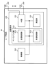
- FIG. 8 is a diagram illustrating an example of the configuration of a base station according to one embodiment.
- the base station 10 comprises a control section 110 , a transmission/reception section 120 , a transmission/reception antenna 130 and a transmission line interface 140 .
- One or more of each of the control unit 110, the transmitting/receiving unit 120, the transmitting/receiving antenna 130, and the transmission path interface 140 may be provided.
- this example mainly shows the functional blocks of the features of the present embodiment, and it may be assumed that the base station 10 also has other functional blocks necessary for wireless communication. A part of the processing of each unit described below may be omitted.
- the control unit 110 controls the base station 10 as a whole.
- the control unit 110 can be configured from a controller, a control circuit, and the like, which are explained based on common recognition in the technical field according to the present disclosure.
- the control unit 110 may control signal generation, scheduling (for example, resource allocation, mapping), and the like.
- the control unit 110 may control transmission/reception, measurement, etc. using the transmission/reception unit 120 , the transmission/reception antenna 130 and the transmission line interface 140 .
- the control unit 110 may generate data to be transmitted as a signal, control information, a sequence, etc., and transfer them to the transmission/reception unit 120 .
- the control unit 110 may perform call processing (setup, release, etc.) of communication channels, state management of the base station 10, management of radio resources, and the like.
- the transmitting/receiving section 120 may include a baseband section 121 , a radio frequency (RF) section 122 and a measuring section 123 .
- the baseband section 121 may include a transmission processing section 1211 and a reception processing section 1212 .
- the transmitting/receiving unit 120 is configured from a transmitter/receiver, an RF circuit, a baseband circuit, a filter, a phase shifter, a measurement circuit, a transmitting/receiving circuit, etc., which are explained based on common recognition in the technical field according to the present disclosure. be able to.
- the transmission/reception unit 120 may be configured as an integrated transmission/reception unit, or may be configured from a transmission unit and a reception unit.
- the transmission section may be composed of the transmission processing section 1211 and the RF section 122 .
- the receiving section may be composed of a reception processing section 1212 , an RF section 122 and a measurement section 123 .
- the transmitting/receiving antenna 130 can be configured from an antenna described based on common recognition in the technical field related to the present disclosure, such as an array antenna.
- the transmitting/receiving unit 120 may transmit the above-described downlink channel, synchronization signal, downlink reference signal, and the like.
- the transmitting/receiving unit 120 may receive the above-described uplink channel, uplink reference signal, and the like.
- the transmitting/receiving unit 120 may form at least one of the transmission beam and the reception beam using digital beamforming (eg, precoding), analog beamforming (eg, phase rotation), or the like.
- digital beamforming eg, precoding
- analog beamforming eg, phase rotation
- the transmission/reception unit 120 (transmission processing unit 1211) performs Packet Data Convergence Protocol (PDCP) layer processing, Radio Link Control (RLC) layer processing (for example, RLC retransmission control), Medium Access Control (MAC) layer processing (for example, HARQ retransmission control), etc. may be performed to generate a bit string to be transmitted.
- PDCP Packet Data Convergence Protocol
- RLC Radio Link Control
- MAC Medium Access Control
- HARQ retransmission control for example, HARQ retransmission control
- the transmission/reception unit 120 (transmission processing unit 1211) performs channel coding (which may include error correction coding), modulation, mapping, filtering, and discrete Fourier transform (DFT) on the bit string to be transmitted. Processing (if necessary), Inverse Fast Fourier Transform (IFFT) processing, precoding, transmission processing such as digital-to-analog conversion may be performed, and the baseband signal may be output.
- channel coding which may include error correction coding
- modulation modulation
- mapping mapping
- filtering filtering
- DFT discrete Fourier transform
- DFT discrete Fourier transform
- the transmitting/receiving unit 120 may perform modulation to a radio frequency band, filter processing, amplification, and the like on the baseband signal, and may transmit the radio frequency band signal via the transmitting/receiving antenna 130. .
- the transmitting/receiving unit 120 may perform amplification, filtering, demodulation to a baseband signal, etc. on the radio frequency band signal received by the transmitting/receiving antenna 130.
- the transmission/reception unit 120 (reception processing unit 1212) performs analog-to-digital conversion, Fast Fourier transform (FFT) processing, and Inverse Discrete Fourier transform (IDFT) processing on the acquired baseband signal. )) processing (if necessary), filtering, demapping, demodulation, decoding (which may include error correction decoding), MAC layer processing, RLC layer processing and PDCP layer processing. User data and the like may be acquired.
- FFT Fast Fourier transform
- IDFT Inverse Discrete Fourier transform
- the transmitting/receiving unit 120 may measure the received signal.
- the measurement unit 123 may perform Radio Resource Management (RRM) measurement, Channel State Information (CSI) measurement, etc. based on the received signal.
- the measurement unit 123 measures received power (for example, Reference Signal Received Power (RSRP)), reception quality (for example, Reference Signal Received Quality (RSRQ), Signal to Interference plus Noise Ratio (SINR), Signal to Noise Ratio (SNR)) , signal strength (for example, Received Signal Strength Indicator (RSSI)), channel information (for example, CSI), and the like may be measured.
- RSRP Reference Signal Received Power
- RSSQ Reference Signal Received Quality
- SINR Signal to Noise Ratio
- RSSI Received Signal Strength Indicator
- channel information for example, CSI
- the transmission path interface 140 transmits and receives signals (backhaul signaling) to and from devices included in the core network 30, other base stations 10, etc., and user data (user plane data) for the user terminal 20, control plane data, and the like. Data and the like may be obtained, transmitted, and the like.
- the transmitting unit and receiving unit of the base station 10 in the present disclosure may be configured by at least one of the transmitting/receiving unit 120, the transmitting/receiving antenna 130, and the transmission line interface 140.
- the transmitting/receiving unit 120 may transmit a transmission configuration indication (TCI) state indication applied to multiple types of channels, and setting information related to the control resource set (CORESET).
- TCI transmission configuration indication
- the configuration information includes, for example, at least the CORESET monitored by the UE, and may additionally include information on the search space set corresponding to the CORESET.
- the control unit 110 controls whether or not to support the operation of setting whether or not the TCI state is applied for each CORESET other than the CORESET having the predetermined index, and the CORESET having the predetermined index. , based on at least one of the second terminal capabilities regarding whether to support the operation of setting whether the TCI state is applied for each CORESET, setting a CORESET having a predetermined index and another CORESET, and a predetermined TCI states corresponding to CORESETs with indices and other CORESETs may be controlled.
- FIG. 9 is a diagram illustrating an example of the configuration of a user terminal according to one embodiment.
- the user terminal 20 includes a control section 210 , a transmission/reception section 220 and a transmission/reception antenna 230 .
- One or more of each of the control unit 210, the transmitting/receiving unit 220, and the transmitting/receiving antenna 230 may be provided.
- this example mainly shows the functional blocks of the features of the present embodiment, and it may be assumed that the user terminal 20 also has other functional blocks necessary for wireless communication. A part of the processing of each unit described below may be omitted.
- the control unit 210 controls the user terminal 20 as a whole.
- the control unit 210 can be configured from a controller, a control circuit, and the like, which are explained based on common recognition in the technical field according to the present disclosure.
- the control unit 210 may control signal generation, mapping, and the like.
- the control unit 210 may control transmission/reception, measurement, etc. using the transmission/reception unit 220 and the transmission/reception antenna 230 .
- the control unit 210 may generate data, control information, sequences, etc. to be transmitted as signals and transfer them to the transmission/reception unit 220 .
- the transmitting/receiving section 220 may include a baseband section 221 , an RF section 222 and a measurement section 223 .
- the baseband section 221 may include a transmission processing section 2211 and a reception processing section 2212 .
- the transmitting/receiving unit 220 can be configured from a transmitter/receiver, an RF circuit, a baseband circuit, a filter, a phase shifter, a measuring circuit, a transmitting/receiving circuit, etc., which are explained based on common recognition in the technical field according to the present disclosure.
- the transmission/reception unit 220 may be configured as an integrated transmission/reception unit, or may be configured from a transmission unit and a reception unit.
- the transmission section may be composed of a transmission processing section 2211 and an RF section 222 .
- the receiving section may include a reception processing section 2212 , an RF section 222 and a measurement section 223 .
- the transmitting/receiving antenna 230 can be configured from an antenna described based on common recognition in the technical field related to the present disclosure, such as an array antenna.
- the transmitting/receiving unit 220 may receive the above-described downlink channel, synchronization signal, downlink reference signal, and the like.
- the transmitting/receiving unit 220 may transmit the above-described uplink channel, uplink reference signal, and the like.
- the transmitter/receiver 220 may form at least one of the transmission beam and the reception beam using digital beamforming (eg, precoding), analog beamforming (eg, phase rotation), or the like.
- digital beamforming eg, precoding
- analog beamforming eg, phase rotation
- the transmitting/receiving unit 220 (transmission processing unit 2211) performs PDCP layer processing, RLC layer processing (eg, RLC retransmission control), MAC layer processing (eg, , HARQ retransmission control) and the like may be performed to generate a bit string to be transmitted.
- RLC layer processing eg, RLC retransmission control
- MAC layer processing eg, HARQ retransmission control
- the transmission/reception unit 220 (transmission processing unit 2211) performs channel coding (which may include error correction coding), modulation, mapping, filtering, DFT processing (if necessary), and IFFT processing on a bit string to be transmitted. , precoding, digital-analog conversion, and other transmission processing may be performed, and the baseband signal may be output.
- Whether or not to apply DFT processing may be based on transform precoding settings. Transmitting/receiving unit 220 (transmission processing unit 2211), for a certain channel (for example, PUSCH), if transform precoding is enabled, the above to transmit the channel using the DFT-s-OFDM waveform
- the DFT process may be performed as the transmission process, or otherwise the DFT process may not be performed as the transmission process.
- the transmitting/receiving unit 220 may perform modulation to a radio frequency band, filter processing, amplification, and the like on the baseband signal, and may transmit the radio frequency band signal via the transmitting/receiving antenna 230. .
- the transmitting/receiving section 220 may perform amplification, filtering, demodulation to a baseband signal, etc. on the radio frequency band signal received by the transmitting/receiving antenna 230.
- the transmission/reception unit 220 (reception processing unit 2212) performs analog-to-digital conversion, FFT processing, IDFT processing (if necessary), filtering, demapping, demodulation, decoding (error correction) on the acquired baseband signal. decoding), MAC layer processing, RLC layer processing, PDCP layer processing, and other reception processing may be applied to acquire user data and the like.
- the transmitting/receiving section 220 may measure the received signal.
- the measurement unit 223 may perform RRM measurement, CSI measurement, etc. based on the received signal.
- the measuring unit 223 may measure received power (eg, RSRP), received quality (eg, RSRQ, SINR, SNR), signal strength (eg, RSSI), channel information (eg, CSI), and the like.
- the measurement result may be output to control section 210 .
- the transmitter and receiver of the user terminal 20 in the present disclosure may be configured by at least one of the transmitter/receiver 220 and the transmitter/receiver antenna 230 .
- the transmitting/receiving unit 220 may receive a transmission configuration indication (TCI) state indication applied to multiple types of channels, and setting information regarding the control resource set (CORESET).
- TCI transmission configuration indication
- CORESET control resource set
- the configuration information includes, for example, at least the CORESET monitored by the UE, and may additionally include information on the search space set corresponding to the CORESET.
- the control unit 210 controls whether or not to support the operation of setting whether or not the TCI state is applied for each CORESET other than the CORESET having the predetermined index, and the CORESET having the predetermined index. , a CORESET having a predetermined index and at least one monitor of the other CORESET based on at least one of the second terminal capabilities regarding whether to support the operation of setting whether or not the TCI state is applied for each CORESET may be controlled.
- control unit 210 may control to apply the TCI state to the other CORESET.
- control unit 210 assumes that no CORESET that supports both the UE-specific search space set and the common search space set is configured, except for the CORESET having the predetermined index. good.
- control unit 210 may control to apply the TCI state to the CORESET having the predetermined index.
- each functional block may be implemented using one device physically or logically coupled, or directly or indirectly using two or more physically or logically separated devices (e.g. , wired, wireless, etc.) and may be implemented using these multiple devices.
- a functional block may be implemented by combining software in the one device or the plurality of devices.
- function includes judgment, decision, determination, calculation, calculation, processing, derivation, investigation, search, confirmation, reception, transmission, output, access, resolution, selection, selection, establishment, comparison, assumption, expectation, deem , broadcasting, notifying, communicating, forwarding, configuring, reconfiguring, allocating, mapping, assigning, etc.
- a functional block (component) that performs transmission may be called a transmitting unit, a transmitter, or the like. In either case, as described above, the implementation method is not particularly limited.
- a base station, a user terminal, etc. in an embodiment of the present disclosure may function as a computer that performs processing of the wireless communication method of the present disclosure.
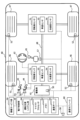
- FIG. 10 is a diagram illustrating an example of hardware configurations of a base station and a user terminal according to one embodiment.
- the base station 10 and user terminal 20 described above may be physically configured as a computer device including a processor 1001, a memory 1002, a storage 1003, a communication device 1004, an input device 1005, an output device 1006, a bus 1007, and the like. .
- the hardware configuration of the base station 10 and the user terminal 20 may be configured to include one or more of each device shown in the figure, or may be configured without some devices.
- processor 1001 may be implemented by one or more chips.
- predetermined software program
- the processor 1001 performs calculations, communication via the communication device 1004 and at least one of reading and writing data in the memory 1002 and the storage 1003 .
- the processor 1001 operates an operating system and controls the entire computer.
- the processor 1001 may be configured by a central processing unit (CPU) including an interface with peripheral devices, a control device, an arithmetic device, registers, and the like.
- CPU central processing unit
- control unit 110 210
- transmission/reception unit 120 220
- FIG. 10 FIG. 10
- the processor 1001 reads programs (program codes), software modules, data, etc. from at least one of the storage 1003 and the communication device 1004 to the memory 1002, and executes various processes according to them.
- programs program codes
- software modules software modules
- data etc.
- the control unit 110 (210) may be implemented by a control program stored in the memory 1002 and running on the processor 1001, and other functional blocks may be similarly implemented.
- the memory 1002 is a computer-readable recording medium, such as Read Only Memory (ROM), Erasable Programmable ROM (EPROM), Electrically EPROM (EEPROM), Random Access Memory (RAM), or at least any other suitable storage medium. may be configured by one.
- the memory 1002 may also be called a register, cache, main memory (main storage device), or the like.
- the memory 1002 can store executable programs (program code), software modules, etc. for implementing a wireless communication method according to an embodiment of the present disclosure.
- the storage 1003 is a computer-readable recording medium, for example, a flexible disk, a floppy (registered trademark) disk, a magneto-optical disk (for example, a compact disk (Compact Disc ROM (CD-ROM), etc.), a digital versatile disk, Blu-ray disc), removable disc, hard disk drive, smart card, flash memory device (e.g., card, stick, key drive), magnetic stripe, database, server, or other suitable storage medium may be configured by Storage 1003 may also be called an auxiliary storage device.
- a computer-readable recording medium for example, a flexible disk, a floppy (registered trademark) disk, a magneto-optical disk (for example, a compact disk (Compact Disc ROM (CD-ROM), etc.), a digital versatile disk, Blu-ray disc), removable disc, hard disk drive, smart card, flash memory device (e.g., card, stick, key drive), magnetic stripe, database, server, or other suitable storage medium may be configured by Storage 1003 may also
- the communication device 1004 is hardware (transmitting/receiving device) for communicating between computers via at least one of a wired network and a wireless network, and is also called a network device, a network controller, a network card, a communication module, or the like.
- the communication device 1004 includes a high-frequency switch, duplexer, filter, frequency synthesizer, etc. in order to realize at least one of frequency division duplex (FDD) and time division duplex (TDD), for example. may be configured to include
- the transmitting/receiving unit 120 (220), the transmitting/receiving antenna 130 (230), and the like described above may be realized by the communication device 1004.
- the transmitter/receiver 120 (220) may be physically or logically separated into a transmitter 120a (220a) and a receiver 120b (220b).
- the input device 1005 is an input device (for example, keyboard, mouse, microphone, switch, button, sensor, etc.) that receives input from the outside.
- the output device 1006 is an output device (for example, a display, a speaker, a Light Emitting Diode (LED) lamp, etc.) that outputs to the outside. Note that the input device 1005 and the output device 1006 may be integrated (for example, a touch panel).
- Each device such as the processor 1001 and the memory 1002 is connected by a bus 1007 for communicating information.
- the bus 1007 may be configured using a single bus, or may be configured using different buses between devices.
- the base station 10 and the user terminal 20 include a microprocessor, a digital signal processor (DSP), an application specific integrated circuit (ASIC), a programmable logic device (PLD), a field programmable gate array (FPGA), etc. It may be configured including hardware, and a part or all of each functional block may be realized using the hardware. For example, processor 1001 may be implemented using at least one of these pieces of hardware.
- DSP digital signal processor
- ASIC application specific integrated circuit
- PLD programmable logic device
- FPGA field programmable gate array
- a signal may also be a message.
- a reference signal may be abbreviated as RS, and may also be called a pilot, a pilot signal, etc., depending on the applicable standard.
- a component carrier may also be called a cell, a frequency carrier, a carrier frequency, or the like.
- a radio frame may consist of one or more periods (frames) in the time domain.
- Each of the one or more periods (frames) that make up a radio frame may be called a subframe.
- a subframe may consist of one or more slots in the time domain.
- a subframe may be a fixed time length (eg, 1 ms) independent of numerology.
- a numerology may be a communication parameter applied to at least one of transmission and reception of a certain signal or channel.
- Numerology for example, subcarrier spacing (SCS), bandwidth, symbol length, cyclic prefix length, transmission time interval (TTI), number of symbols per TTI, radio frame configuration , a particular filtering process performed by the transceiver in the frequency domain, a particular windowing process performed by the transceiver in the time domain, and/or the like.
- a slot may consist of one or more symbols (Orthogonal Frequency Division Multiplexing (OFDM) symbol, Single Carrier Frequency Division Multiple Access (SC-FDMA) symbol, etc.) in the time domain.
- OFDM Orthogonal Frequency Division Multiplexing
- SC-FDMA Single Carrier Frequency Division Multiple Access
- a slot may also be a unit of time based on numerology.
- a slot may contain multiple mini-slots. Each minislot may consist of one or more symbols in the time domain. A minislot may also be referred to as a subslot. A minislot may consist of fewer symbols than a slot.
- a PDSCH (or PUSCH) transmitted in time units larger than a minislot may be referred to as PDSCH (PUSCH) Mapping Type A.
- PDSCH (or PUSCH) transmitted using minislots may be referred to as PDSCH (PUSCH) mapping type B.
- Radio frames, subframes, slots, minislots and symbols all represent time units when transmitting signals. Radio frames, subframes, slots, minislots and symbols may be referred to by other corresponding designations. Note that time units such as frames, subframes, slots, minislots, and symbols in the present disclosure may be read interchangeably.
- one subframe may be called a TTI
- a plurality of consecutive subframes may be called a TTI
- one slot or one minislot may be called a TTI. That is, at least one of the subframe and TTI may be a subframe (1 ms) in existing LTE, a period shorter than 1 ms (eg, 1-13 symbols), or a period longer than 1 ms may be Note that the unit representing the TTI may be called a slot, mini-slot, or the like instead of a subframe.
- TTI refers to, for example, the minimum scheduling time unit in wireless communication.
- a base station performs scheduling to allocate radio resources (frequency bandwidth, transmission power, etc. that can be used by each user terminal) to each user terminal on a TTI basis.
- radio resources frequency bandwidth, transmission power, etc. that can be used by each user terminal
- a TTI may be a transmission time unit such as a channel-encoded data packet (transport block), code block, or codeword, or may be a processing unit such as scheduling and link adaptation. Note that when a TTI is given, the time interval (for example, the number of symbols) in which transport blocks, code blocks, codewords, etc. are actually mapped may be shorter than the TTI.
- one or more TTIs may be the minimum scheduling time unit. Also, the number of slots (the number of mini-slots) constituting the minimum time unit of the scheduling may be controlled.
- a TTI having a time length of 1 ms may be called a normal TTI (TTI in 3GPP Rel. 8-12), normal TTI, long TTI, normal subframe, normal subframe, long subframe, slot, or the like.
- a TTI that is shorter than a normal TTI may be called a shortened TTI, a short TTI, a partial or fractional TTI, a shortened subframe, a short subframe, a minislot, a subslot, a slot, and the like.
- the long TTI (e.g., normal TTI, subframe, etc.) may be replaced with a TTI having a time length exceeding 1 ms
- the short TTI e.g., shortened TTI, etc.
- a TTI having the above TTI length may be read instead.
- a resource block is a resource allocation unit in the time domain and frequency domain, and may include one or more consecutive subcarriers (subcarriers) in the frequency domain.
- the number of subcarriers included in the RB may be the same regardless of the neumerology, eg twelve.
- the number of subcarriers included in an RB may be determined based on neumerology.
- an RB may contain one or more symbols in the time domain and may be 1 slot, 1 minislot, 1 subframe or 1 TTI long.
- One TTI, one subframe, etc. may each be configured with one or more resource blocks.
- One or more RBs are Physical Resource Block (PRB), Sub-Carrier Group (SCG), Resource Element Group (REG), PRB pair, RB Also called a pair.
- PRB Physical Resource Block
- SCG Sub-Carrier Group
- REG Resource Element Group
- PRB pair RB Also called a pair.
- a resource block may be composed of one or more resource elements (Resource Element (RE)).
- RE resource elements
- 1 RE may be a radio resource region of 1 subcarrier and 1 symbol.
- a Bandwidth Part (which may also be called a bandwidth part) represents a subset of contiguous common resource blocks (RBs) for a numerology on a carrier.
- the common RB may be identified by an RB index based on the common reference point of the carrier.
- PRBs may be defined in a BWP and numbered within that BWP.
- BWP may include UL BWP (BWP for UL) and DL BWP (BWP for DL).
- BWP for UL
- BWP for DL DL BWP
- One or multiple BWPs may be configured for a UE within one carrier.
- At least one of the configured BWPs may be active, and the UE may not expect to transmit or receive a given signal/channel outside the active BWP.
- BWP bitmap
- radio frames, subframes, slots, minislots, symbols, etc. described above are merely examples.
- the number of subframes contained in a radio frame, the number of slots per subframe or radio frame, the number of minislots contained within a slot, the number of symbols and RBs contained in a slot or minislot, the number of Configurations such as the number of subcarriers and the number of symbols in a TTI, symbol length, cyclic prefix (CP) length, etc. can be varied.
- the information, parameters, etc. described in the present disclosure may be expressed using absolute values, may be expressed using relative values from a predetermined value, or may be expressed using other corresponding information. may be represented. For example, radio resources may be indicated by a predetermined index.
- data, instructions, commands, information, signals, bits, symbols, chips, etc. may refer to voltages, currents, electromagnetic waves, magnetic fields or magnetic particles, light fields or photons, or any of these. may be represented by a combination of
- information, signals, etc. can be output from a higher layer to a lower layer and/or from a lower layer to a higher layer.
- Information, signals, etc. may be input and output through multiple network nodes.
- Input/output information, signals, etc. may be stored in a specific location (for example, memory), or may be managed using a management table. Input and output information, signals, etc. may be overwritten, updated or appended. Output information, signals, etc. may be deleted. Input information, signals, etc. may be transmitted to other devices.
- Uplink Control Information (UCI) Uplink Control Information
- RRC Radio Resource Control
- MIB Master Information Block
- SIB System Information Block
- SIB System Information Block
- MAC Medium Access Control
- the physical layer signaling may also be called Layer 1/Layer 2 (L1/L2) control information (L1/L2 control signal), L1 control information (L1 control signal), and the like.
- RRC signaling may also be called an RRC message, and may be, for example, an RRC connection setup message, an RRC connection reconfiguration message, or the like.
- MAC signaling may be notified using, for example, a MAC Control Element (CE).
- CE MAC Control Element
- notification of predetermined information is not limited to explicit notification, but implicit notification (for example, by not notifying the predetermined information or by providing another information by notice of
- the determination may be made by a value (0 or 1) represented by 1 bit, or by a boolean value represented by true or false. , may be performed by numerical comparison (eg, comparison with a predetermined value).
- Software whether referred to as software, firmware, middleware, microcode, hardware description language or otherwise, includes instructions, instruction sets, code, code segments, program code, programs, subprograms, and software modules. , applications, software applications, software packages, routines, subroutines, objects, executables, threads of execution, procedures, functions, and the like.
- software, instructions, information, etc. may be transmitted and received via a transmission medium.
- the software uses wired technology (coaxial cable, fiber optic cable, twisted pair, Digital Subscriber Line (DSL), etc.) and/or wireless technology (infrared, microwave, etc.) , a server, or other remote source, these wired and/or wireless technologies are included within the definition of transmission media.
- a “network” may refer to devices (eg, base stations) included in a network.
- precoding "precoding weight”
- QCL Quality of Co-Location
- TCI state Transmission Configuration Indication state
- spatialal patial relation
- spatialal domain filter "transmission power”
- phase rotation "antenna port
- antenna port group "layer”
- number of layers Terms such as “rank”, “resource”, “resource set”, “resource group”, “beam”, “beam width”, “beam angle”, “antenna”, “antenna element”, “panel” are interchangeable. can be used as intended.
- base station BS
- radio base station fixed station
- NodeB NodeB
- eNB eNodeB
- gNB gNodeB
- Access point "Transmission Point (TP)”, “Reception Point (RP)”, “Transmission/Reception Point (TRP)”, “Panel”
- a base station may also be referred to by terms such as macrocell, small cell, femtocell, picocell, and the like.
- a base station can accommodate one or more (eg, three) cells.
- the overall coverage area of the base station can be partitioned into multiple smaller areas, and each smaller area is assigned to a base station subsystem (e.g., a small indoor base station (Remote Radio)). Head (RRH))) may also provide communication services.
- a base station subsystem e.g., a small indoor base station (Remote Radio)). Head (RRH)
- RRH Head
- the terms "cell” or “sector” refer to part or all of the coverage area of at least one of the base stations and base station subsystems that serve communication within such coverage.
- MS Mobile Station
- UE User Equipment
- Mobile stations include subscriber stations, mobile units, subscriber units, wireless units, remote units, mobile devices, wireless devices, wireless communication devices, remote devices, mobile subscriber stations, access terminals, mobile terminals, wireless terminals, remote terminals. , a handset, a user agent, a mobile client, a client, or some other suitable term.
- At least one of the base station and the mobile station may be called a transmitting device, a receiving device, a wireless communication device, or the like. At least one of the base station and the mobile station may be a device mounted on a moving object, the mobile itself, or the like.
- the moving body refers to a movable object, the speed of movement is arbitrary, and it naturally includes cases where the moving body is stationary.
- Examples of such moving bodies include vehicles, transportation vehicles, automobiles, motorcycles, bicycles, connected cars, excavators, bulldozers, wheel loaders, dump trucks, forklifts, trains, buses, carts, rickshaws, and ships (ships and other watercraft). , airplanes, rockets, satellites, drones, multi-copters, quad-copters, balloons and objects mounted on them.
- the mobile body may be a mobile body that autonomously travels based on an operation command.
- the mobile object may be a vehicle (e.g., car, airplane, etc.), an unmanned mobile object (e.g., drone, self-driving car, etc.), or a robot (manned or unmanned ).
- a vehicle e.g., car, airplane, etc.
- an unmanned mobile object e.g., drone, self-driving car, etc.
- a robot manned or unmanned .
- at least one of the base station and the mobile station includes devices that do not necessarily move during communication operations.
- at least one of the base station and mobile station may be an Internet of Things (IoT) device such as a sensor.
- IoT Internet of Things
- FIG. 11 is a diagram showing an example of a vehicle according to one embodiment.
- the vehicle 40 includes a drive unit 41, a steering unit 42, an accelerator pedal 43, a brake pedal 44, a shift lever 45, left and right front wheels 46, left and right rear wheels 47, an axle 48, an electronic control unit 49, various sensors (current sensor 50, revolution sensor 51, air pressure sensor 52, vehicle speed sensor 53, acceleration sensor 54, accelerator pedal sensor 55, brake pedal sensor 56, shift lever sensor 57, and object detection sensor 58), information service unit 59 and communication module 60.
- various sensors current sensor 50, revolution sensor 51, air pressure sensor 52, vehicle speed sensor 53, acceleration sensor 54, accelerator pedal sensor 55, brake pedal sensor 56, shift lever sensor 57, and object detection sensor 58
- information service unit 59 and communication module 60.
- the driving unit 41 is composed of, for example, at least one of an engine, a motor, and a hybrid of an engine and a motor.
- the steering unit 42 includes at least a steering wheel (also referred to as a steering wheel), and is configured to steer at least one of the front wheels 46 and the rear wheels 47 based on the operation of the steering wheel operated by the user.
- the electronic control unit 49 is composed of a microprocessor 61 , a memory (ROM, RAM) 62 , and a communication port (eg, input/output (IO) port) 63 . Signals from various sensors 50 to 58 provided in the vehicle are input to the electronic control unit 49 .
- the electronic control unit 49 may be called an Electronic Control Unit (ECU).
- ECU Electronic Control Unit
- the signals from the various sensors 50 to 58 include a current signal from the current sensor 50 that senses the current of the motor, a rotation speed signal of the front wheels 46/rear wheels 47 obtained by the rotation speed sensor 51, and an air pressure sensor 52.
- air pressure signal of front wheels 46/rear wheels 47 vehicle speed signal obtained by vehicle speed sensor 53, acceleration signal obtained by acceleration sensor 54, depression amount signal of accelerator pedal 43 obtained by accelerator pedal sensor 55, brake pedal sensor
- the information service unit 59 includes various devices such as car navigation systems, audio systems, speakers, displays, televisions, and radios for providing (outputting) various information such as driving information, traffic information, and entertainment information, and these devices. and one or more ECUs that control The information service unit 59 provides various information/services (for example, multimedia information/multimedia services) to the occupants of the vehicle 40 using information acquired from an external device via the communication module 60 or the like.
- various information/services for example, multimedia information/multimedia services
- the information service unit 59 may include an input device (e.g., keyboard, mouse, microphone, switch, button, sensor, touch panel, etc.) that receives input from the outside, and an output device that outputs to the outside (e.g., display, speaker, LED lamp, touch panel, etc.).
- an input device e.g., keyboard, mouse, microphone, switch, button, sensor, touch panel, etc.
- an output device e.g., display, speaker, LED lamp, touch panel, etc.
- the driving support system unit 64 includes a millimeter wave radar, Light Detection and Ranging (LiDAR), a camera, a positioning locator (e.g., Global Navigation Satellite System (GNSS), etc.), map information (e.g., High Definition (HD)) maps, autonomous vehicle (AV) maps, etc.), gyro systems (e.g., inertial measurement units (IMU), inertial navigation systems (INS), etc.), artificial intelligence ( Artificial intelligence (AI) chips, AI processors, and other devices that provide functions to prevent accidents and reduce the driver's driving load, and one or more devices that control these devices ECU.
- the driving support system unit 64 transmits and receives various information via the communication module 60, and realizes a driving support function or an automatic driving function.
- the communication module 60 can communicate with the microprocessor 61 and components of the vehicle 40 via the communication port 63 .
- the communication module 60 communicates with the vehicle 40 through a communication port 63 such as a driving unit 41, a steering unit 42, an accelerator pedal 43, a brake pedal 44, a shift lever 45, left and right front wheels 46, left and right rear wheels 47, Data (information) is transmitted and received between the axle 48, the microprocessor 61 and memory (ROM, RAM) 62 in the electronic control unit 49, and various sensors 50-58.
- the communication module 60 is a communication device that can be controlled by the microprocessor 61 of the electronic control unit 49 and can communicate with an external device. For example, it transmits and receives various information to and from an external device via wireless communication.
- Communication module 60 may be internal or external to electronic control 49 .
- the external device may be, for example, the above-described base station 10, user terminal 20, or the like.
- the communication module 60 may be, for example, at least one of the base station 10 and the user terminal 20 described above (and may function as at least one of the base station 10 and the user terminal 20).
- the communication module 60 receives signals from the various sensors 50 to 58 described above input to the electronic control unit 49, information obtained based on the signals, and input from the outside (user) obtained via the information service unit 59. may be transmitted to the external device via wireless communication.
- the electronic control unit 49, the various sensors 50-58, the information service unit 59, etc. may be called an input unit that receives input.
- the PUSCH transmitted by communication module 60 may include information based on the above inputs.
- the communication module 60 receives various information (traffic information, signal information, inter-vehicle information, etc.) transmitted from an external device and displays it on the information service unit 59 provided in the vehicle.
- the information service unit 59 is an output unit that outputs information (for example, outputs information to devices such as displays and speakers based on the PDSCH received by the communication module 60 (or data/information decoded from the PDSCH)). may be called
- the communication module 60 stores various information received from an external device in a memory 62 that can be used by the microprocessor 61 . Based on the information stored in the memory 62, the microprocessor 61 controls the drive unit 41, the steering unit 42, the accelerator pedal 43, the brake pedal 44, the shift lever 45, the left and right front wheels 46, and the left and right rear wheels provided in the vehicle 40. 47, axle 48, and various sensors 50-58 may be controlled.
- the base station in the present disclosure may be read as a user terminal.
- communication between a base station and a user terminal is replaced with communication between multiple user terminals (for example, Device-to-Device (D2D), Vehicle-to-Everything (V2X), etc.)
- the user terminal 20 may have the functions of the base station 10 described above.
- words such as "uplink” and “downlink” may be replaced with words corresponding to communication between terminals (for example, "sidelink”).
- uplink channels, downlink channels, etc. may be read as sidelink channels.
- user terminals in the present disclosure may be read as base stations.
- the base station 10 may have the functions of the user terminal 20 described above.
- operations that are assumed to be performed by the base station may be performed by its upper node in some cases.
- various operations performed for communication with a terminal may involve the base station, one or more network nodes other than the base station (e.g., Clearly, this can be done by a Mobility Management Entity (MME), Serving-Gateway (S-GW), etc. (but not limited to these) or a combination thereof.
- MME Mobility Management Entity
- S-GW Serving-Gateway
- each aspect/embodiment described in the present disclosure may be used alone, may be used in combination, or may be used by switching along with execution. Also, the processing procedures, sequences, flowcharts, etc. of each aspect/embodiment described in the present disclosure may be rearranged as long as there is no contradiction. For example, the methods described in this disclosure present elements of the various steps using a sample order, and are not limited to the specific order presented.
- LTE Long Term Evolution
- LTE-A LTE-Advanced
- LTE-B LTE-Beyond
- SUPER 3G IMT-Advanced
- 4G 4th generation mobile communication system
- 5G 5th generation mobile communication system
- 6G 6th generation mobile communication system
- xG x is, for example, an integer or a decimal number
- Future Radio Access FAA
- RAT New-Radio Access Technology
- NR New Radio
- NX New radio access
- FX Future generation radio access
- GSM registered trademark
- CDMA2000 Code Division Multiple Access
- UMB Ultra Mobile Broadband
- IEEE 802 .11 Wi-Fi®
- IEEE 802.16 WiMAX®
- IEEE 802.20 Ultra-WideBand (UWB), Bluetooth®, or any other suitable wireless communication method. It may be applied to a system to be used, a next-generation system extended, modified, created or defined based on these.
- any reference to elements using the "first,” “second,” etc. designations used in this disclosure does not generally limit the quantity or order of those elements. These designations may be used in this disclosure as a convenient method of distinguishing between two or more elements. Thus, references to first and second elements do not imply that only two elements may be employed or that the first element must precede the second element in any way.
- determining includes judging, calculating, computing, processing, deriving, investigating, looking up, searching, inquiry ( For example, looking up in a table, database, or another data structure), ascertaining, etc. may be considered to be “determining.”
- determining (deciding) includes receiving (e.g., receiving information), transmitting (e.g., transmitting information), input, output, access ( accessing (e.g., accessing data in memory), etc.
- determining is considered to be “determining” resolving, selecting, choosing, establishing, comparing, etc. good too. That is, “determining (determining)” may be regarded as “determining (determining)” some action.
- Maximum transmit power described in this disclosure may mean the maximum value of transmit power, may mean the nominal maximum transmit power (the nominal UE maximum transmit power), or may mean the rated maximum transmit power (the rated UE maximum transmit power).
- connection refers to any connection or coupling, direct or indirect, between two or more elements. and can include the presence of one or more intermediate elements between two elements that are “connected” or “coupled” to each other. Couplings or connections between elements may be physical, logical, or a combination thereof. For example, "connection” may be read as "access”.
- radio frequency domain when two elements are connected, using one or more wires, cables, printed electrical connections, etc., and as some non-limiting and non-exhaustive examples, radio frequency domain, microwave They can be considered to be “connected” or “coupled” together using the domain, electromagnetic energy having wavelengths in the optical (both visible and invisible) domain, and the like.
- a and B are different may mean “A and B are different from each other.”
- the term may also mean that "A and B are different from C”.
- Terms such as “separate,” “coupled,” etc. may also be interpreted in the same manner as “different.”
Abstract
A TCI state is appropriately determined. A terminal according to an aspect of the present disclosure includes: a receiving unit that receives an instruction for a transmission configuration indication (TCI) state to be applied to multiple types of channels, and setting information relating to a control resource set (CORESET); and a control unit that, on the basis of a first terminal capability related to whether or not to support an operation of setting whether or not the TCI state is applied for each CORESET among other CORESETs excluding CORESETs having a predetermined index, and/or a second terminal capability related to whether or not to support the operation of setting whether or not the TCI state is applied for each CORESET among CORESETs having the predetermined index, controls at least one monitor of the CORESETs having the predetermined index and the other CORESETs.
Description
本開示は、次世代移動通信システムにおける端末、無線通信方法及び基地局に関する。
The present disclosure relates to terminals, wireless communication methods, and base stations in next-generation mobile communication systems.
Universal Mobile Telecommunications System(UMTS)ネットワークにおいて、更なる高速データレート、低遅延などを目的としてLong Term Evolution(LTE)が仕様化された(非特許文献1)。また、LTE(Third Generation Partnership Project(3GPP) Release(Rel.)8、9)の更なる大容量、高度化などを目的として、LTE-Advanced(3GPP Rel.10-14)が仕様化された。
In the Universal Mobile Telecommunications System (UMTS) network, Long Term Evolution (LTE) has been specified for the purpose of further high data rate, low delay, etc. (Non-Patent Document 1). In addition, LTE-Advanced (3GPP Rel. 10-14) has been specified for the purpose of further increasing the capacity and sophistication of LTE (Third Generation Partnership Project (3GPP) Release (Rel.) 8, 9).
LTEの後継システム(例えば、5th generation mobile communication system(5G)、5G+(plus)、6th generation mobile communication system(6G)、New Radio(NR)、3GPP Rel.15以降などともいう)も検討されている。
LTE successor systems (for example, 5th generation mobile communication system (5G), 5G+ (plus), 6th generation mobile communication system (6G), New Radio (NR), 3GPP Rel. 15 and later) are also being considered. .
将来の無線通信システム(例えば、NR)において、ユーザ端末(端末、user terminal、User Equipment(UE))は、疑似コロケーション(Quasi-Co-Location(QCL))に関する情報(QCL想定/Transmission Configuration Indication(TCI)状態/空間関係)に基づいて、送受信処理を制御することが検討されている。
In future wireless communication systems (for example, NR), user terminals (terminals, user terminals, User Equipment (UE)) will receive information (QCL assumption/Transmission Configuration Indication ( It has been considered to control transmission and reception processes based on TCI (state/space relationship).
設定/アクティベート/指示されたTCI状態をチャネル/reference signal(RS)の複数種類に適用する統一TCI状態が検討されている。しかしながら、コントロールリソースセット(CORESET)のTCI状態と、統一TCI状態と、の関係が明らかでない。このような関係が明らかでなければ、通信品質の低下、スループットの低下など、を招くおそれがある。
A unified TCI state is being considered that applies the set/activated/indicated TCI state to multiple types of channels/reference signals (RS). However, the relationship between the TCI state of the control resource set (CORESET) and the unified TCI state is not clear. If such a relationship is not clear, there is a risk of deterioration in communication quality and throughput.
そこで、本開示は、TCI状態を適切に決定する端末、無線通信方法及び基地局を提供することを目的の1つとする。
Therefore, one object of the present disclosure is to provide a terminal, a wireless communication method, and a base station that appropriately determine the TCI state.
本開示の一態様に係る端末は、複数種類のチャネルに適用されるtransmission configuration indication(TCI)状態の指示と、制御リソースセット(CORESET)に関する設定情報と、を受信する受信部と、所定インデックスを有するCORESETを除く他のCORESETに対して、前記TCI状態の適用有無をCORESET毎に設定する動作をサポートするか否かに関する第1の端末能力、及び前記所定インデックスを有するCORESETに対して、前記TCI状態の適用有無をCORESET毎に設定する動作をサポートするか否かに関する第2の端末能力の少なくとも一つに基づいて、前記所定インデックスを有するCORESET及び前記他のCORESETの少なくとも一つのモニタを制御する制御部と、を有する。
A terminal according to an aspect of the present disclosure includes a transmission configuration indication (TCI) state indication applied to multiple types of channels, a receiving unit that receives setting information about a control resource set (CORESET), and a predetermined index. a first terminal capability related to whether or not to support an operation of setting whether or not the TCI state is applied for each CORESET, for other CORESETs other than the CORESET having the predetermined index, and for the CORESET having the predetermined index, the TCI Controlling monitoring of at least one of the CORESET having the predetermined index and the other CORESET based on at least one of second terminal capabilities regarding whether or not to support an operation of setting whether or not the state is applied for each CORESET. and a control unit.
本開示の一態様によれば、TCI状態を適切に決定できる。
According to one aspect of the present disclosure, the TCI state can be determined appropriately.
(TCI、空間関係、QCL)
NRでは、送信設定指示状態(Transmission Configuration Indication state(TCI状態))に基づいて、信号及びチャネルの少なくとも一方(信号/チャネルと表現する)のUEにおける受信処理(例えば、受信、デマッピング、復調、復号の少なくとも1つ)、送信処理(例えば、送信、マッピング、プリコーディング、変調、符号化の少なくとも1つ)を制御することが検討されている。 (TCI, spatial relations, QCL)
In NR, the reception processing (e.g., reception, demapping, demodulation, decoding), transmission processing (eg, at least one of transmission, mapping, precoding, modulation, encoding).
TCI状態は下りリンクの信号/チャネルに適用されるものを表してもよい。上りリンクの信号/チャネルに適用されるTCI状態に相当するものは、空間関係(spatial relation)と表現されてもよい。
The TCI state may represent those that apply to downlink signals/channels. The equivalent of TCI conditions applied to uplink signals/channels may be expressed as spatial relations.
TCI状態とは、信号/チャネルの疑似コロケーション(Quasi-Co-Location(QCL))に関する情報であり、空間受信パラメータ、空間関係情報(Spatial Relation Information)などと呼ばれてもよい。TCI状態は、チャネルごと又は信号ごとにUEに設定されてもよい。
The TCI state is information about the pseudo-co-location (QCL) of signals/channels, and may be called spatial reception parameters, spatial relation information, or the like. The TCI state may be set in the UE on a channel-by-channel or signal-by-signal basis.
QCLとは、信号/チャネルの統計的性質を示す指標である。例えば、ある信号/チャネルと他の信号/チャネルがQCLの関係である場合、これらの異なる複数の信号/チャネル間において、ドップラーシフト(Doppler shift)、ドップラースプレッド(Doppler spread)、平均遅延(average delay)、遅延スプレッド(delay spread)、空間パラメータ(spatial parameter)(例えば、空間受信パラメータ(spatial Rx parameter))の少なくとも1つが同一である(これらの少なくとも1つに関してQCLである)と仮定できることを意味してもよい。
QCL is an index that indicates the statistical properties of a signal/channel. For example, when one signal/channel and another signal/channel have a QCL relationship, Doppler shift, Doppler spread, average delay ), delay spread, spatial parameters (e.g., spatial Rx parameter) are identical (QCL with respect to at least one of these). You may
なお、空間受信パラメータは、UEの受信ビーム(例えば、受信アナログビーム)に対応してもよく、空間的QCLに基づいてビームが特定されてもよい。本開示におけるQCL(又はQCLの少なくとも1つの要素)は、sQCL(spatial QCL)で読み替えられてもよい。
Note that the spatial reception parameters may correspond to the reception beams of the UE (eg, reception analog beams), and the beams may be specified based on the spatial QCL. QCL (or at least one element of QCL) in the present disclosure may be read as sQCL (spatial QCL).
QCLは、複数のタイプ(QCLタイプ)が規定されてもよい。例えば、同一であると仮定できるパラメータ(又はパラメータセット)が異なる4つのQCLタイプA-Dが設けられてもよく、以下に当該パラメータ(QCLパラメータと呼ばれてもよい)について示す:
・QCLタイプA(QCL-A):ドップラーシフト、ドップラースプレッド、平均遅延及び遅延スプレッド、
・QCLタイプB(QCL-B):ドップラーシフト及びドップラースプレッド、
・QCLタイプC(QCL-C):ドップラーシフト及び平均遅延、
・QCLタイプD(QCL-D):空間受信パラメータ。 A plurality of types (QCL types) may be defined for the QCL. For example, four QCL types AD may be provided with different parameters (or parameter sets) that can be assumed to be the same, and the parameters (which may be referred to as QCL parameters) are shown below:
QCL type A (QCL-A): Doppler shift, Doppler spread, mean delay and delay spread,
QCL type B (QCL-B): Doppler shift and Doppler spread,
QCL type C (QCL-C): Doppler shift and mean delay;
• QCL Type D (QCL-D): Spatial reception parameters.
ある制御リソースセット(Control Resource Set(CORESET))、チャネル又は参照信号が、別のCORESET、チャネル又は参照信号と特定のQCL(例えば、QCLタイプD)の関係にあるとUEが想定することは、QCL想定(QCL assumption)と呼ばれてもよい。
The UE's assumption that one Control Resource Set (CORESET), channel, or reference signal is in a specific QCL (e.g., QCL type D) relationship with another CORESET, channel, or reference signal is It may be called the QCL assumption.
UEは、信号/チャネルのTCI状態又はQCL想定に基づいて、当該信号/チャネルの送信ビーム(Txビーム)及び受信ビーム(Rxビーム)の少なくとも1つを決定してもよい。
A UE may determine at least one of a transmit beam (Tx beam) and a receive beam (Rx beam) for a signal/channel based on the TCI conditions or QCL assumptions of that signal/channel.
TCI状態は、例えば、対象となるチャネル(言い換えると、当該チャネル用の参照信号(Reference Signal(RS)))と、別の信号(例えば、別のRS)とのQCLに関する情報であってもよい。TCI状態は、上位レイヤシグナリング、物理レイヤシグナリング又はこれらの組み合わせによって設定(指示)されてもよい。
The TCI state may be, for example, information about the QCL between the channel of interest (in other words, the reference signal (RS) for the channel) and another signal (for example, another RS). . The TCI state may be set (indicated) by higher layer signaling, physical layer signaling or a combination thereof.
物理レイヤシグナリングは、例えば、下り制御情報(Downlink Control Information(DCI))であってもよい。
Physical layer signaling may be, for example, downlink control information (DCI).
TCI状態又は空間関係が設定(指定)されるチャネルは、例えば、下り共有チャネル(Physical Downlink Shared Channel(PDSCH))、下り制御チャネル(Physical Downlink Control Channel(PDCCH))、上り共有チャネル(Physical Uplink Shared Channel(PUSCH))、上り制御チャネル(Physical Uplink Control Channel(PUCCH))の少なくとも1つであってもよい。
Channels for which TCI states or spatial relationships are set (specified) are, for example, Physical Downlink Shared Channel (PDSCH), Physical Downlink Control Channel (PDCCH), Physical Uplink Shared Channel It may be at least one of a channel (PUSCH)) and an uplink control channel (Physical Uplink Control Channel (PUCCH)).
また、当該チャネルとQCL関係となるRSは、例えば、同期信号ブロック(Synchronization Signal Block(SSB))、チャネル状態情報参照信号(Channel State Information Reference Signal(CSI-RS))、測定用参照信号(Sounding Reference Signal(SRS))、トラッキング用CSI-RS(Tracking Reference Signal(TRS)とも呼ぶ)、QCL検出用参照信号(QRSとも呼ぶ)の少なくとも1つであってもよい。
In addition, RSs that have a QCL relationship with the channel are, for example, a synchronization signal block (SSB), a channel state information reference signal (CSI-RS), a measurement reference signal (Sounding It may be at least one of a reference signal (SRS)), a tracking CSI-RS (also called a tracking reference signal (TRS)), and a QCL detection reference signal (also called a QRS).
SSBは、プライマリ同期信号(Primary Synchronization Signal(PSS))、セカンダリ同期信号(Secondary Synchronization Signal(SSS))及びブロードキャストチャネル(Physical Broadcast Channel(PBCH))の少なくとも1つを含む信号ブロックである。SSBは、SS/PBCHブロックと呼ばれてもよい。
An SSB is a signal block that includes at least one of a Primary Synchronization Signal (PSS), a Secondary Synchronization Signal (SSS), and a Physical Broadcast Channel (PBCH). An SSB may also be called an SS/PBCH block.
TCI状態のQCLタイプXのRSは、あるチャネル/信号(のDMRS)とQCLタイプXの関係にあるRSを意味してもよく、このRSは当該TCI状態のQCLタイプXのQCLソースと呼ばれてもよい。
A QCL type X RS in a TCI state may mean an RS that has a QCL type X relationship with (the DMRS of) a certain channel/signal, and this RS is called a QCL type X QCL source in that TCI state. may
(統一(unified)/共通(common)TCIフレームワーク)
統一TCIフレームワークによれば、UL及びDLのチャネルを共通のフレームワークによって制御できる。統一TCIフレームワークは、Rel.15のようにTCI状態又は空間関係をチャネルごとに規定するのではなく、共通ビーム(共通TCI状態)を指示し、それをUL及びDLの全てのチャネルへ適用してもよいし、UL用の共通ビームをULの全てのチャネルに適用し、DL用の共通ビームをDLの全てのチャネルに適用してもよい。 (Unified/Common TCI Framework)
The unified TCI framework allows UL and DL channels to be controlled by a common framework. The unified TCI framework is Rel. Instead of defining TCI conditions or spatial relationships per channel as in 15, a common beam (common TCI condition) may be indicated and applied to all channels in the UL and DL, or for the UL A common beam may be applied to all channels in the UL and a common beam for the DL may be applied to all channels in the DL.
DL及びULの両方のための1つの共通ビーム、又は、DL用の共通ビームとUL用の共通ビーム(全体で2つの共通ビーム)が検討されている。
One common beam for both DL and UL, or a common beam for DL and a common beam for UL (two common beams in total) are being considered.
UEは、UL及びDLに対して同じTCI状態(ジョイントTCI状態、ジョイントTCIプール、ジョイント共通TCIプール、ジョイントTCI状態セット)を想定してもよい。UEは、UL及びDLのそれぞれに対して異なるTCI状態(セパレートTCI状態、セパレートTCIプール、ULセパレートTCIプール及びDLセパレートTCIプール、セパレート共通TCIプール、UL共通TCIプール及びDL共通TCIプール)を想定してもよい。
The UE may assume the same TCI state (joint TCI state, joint TCI pool, joint common TCI pool, joint TCI state set) for UL and DL. The UE assumes different TCI states for each of UL and DL (separate TCI state, separate TCI pool, UL separate TCI pool and DL separate TCI pool, separate common TCI pool, UL common TCI pool and DL common TCI pool). You may
MAC CEに基づくビーム管理(MAC CEレベルビーム指示)によって、UL及びDLのデフォルトビームを揃えてもよい。PDSCHのデフォルトTCI状態を更新し、デフォルトULビーム(空間関係)に合わせてもよい。
The UL and DL default beams may be aligned by MAC CE-based beam management (MAC CE level beam designation). The PDSCH default TCI state may be updated to match the default UL beam (spatial relationship).
DCIに基づくビーム管理(DCIレベルビーム指示)によって、UL及びDLの両方用の同じTCIプール(ジョイント共通TCIプール、ジョイントTCIプール、セット)から共通ビーム/統一TCI状態が指示されてもよい。X(>1)個のTCI状態がMAC CEによってアクティベートされてもよい。UL/DL DCIは、X個のアクティブTCI状態から1つを選択してもよい。選択されたTCI状態は、UL及びDLの両方のチャネル/RSに適用されてもよい。
DCI-based beam management (DCI level beam indication) may indicate common beam/unified TCI state from the same TCI pool for both UL and DL (joint common TCI pool, joint TCI pool, set). X (>1) TCI states may be activated by MAC CE. The UL/DL DCI may select 1 out of X active TCI states. The selected TCI state may apply to both UL and DL channels/RS.
TCIプール(セット)は、RRCパラメータによって設定された複数のTCI状態であってもよいし、RRCパラメータによって設定された複数のTCI状態のうち、MAC CEによってアクティベートされた複数のTCI状態(アクティブTCI状態、アクティブTCIプール、セット)であってもよい。各TCI状態は、QCLタイプA/D RSであってもよい。QCLタイプA/D RSとしてSSB、CSI-RS、又はSRSが設定されてもよい。
The TCI pool (set) may be a plurality of TCI states set by RRC parameters, or a plurality of TCI states activated by MAC CE (active TCI state, active TCI pool, set). Each TCI state may be a QCL type A/D RS. SSB, CSI-RS, or SRS may be set as QCL type A/D RS.
1以上のTRPのそれぞれに対応するTCI状態の個数が規定されてもよい。例えば、ULのチャネル/RSに適用されるTCI状態(UL TCI状態)の個数N(≧1)と、DLのチャネル/RSに適用されるTCI状態(DL TCI状態)の個数M(≧1)と、が規定されてもよい。N及びMの少なくとも一方は、上位レイヤシグナリング/物理レイヤシグナリングを介して、UEに通知/設定/指示されてもよい。
The number of TCI states corresponding to each of one or more TRPs may be defined. For example, the number N (≧1) of TCI states (UL TCI states) applied to UL channels/RSs and the number M (≧1) of TCI states (DL TCI states) applied to DL channels/RSs and may be defined. At least one of N and M may be signaled/configured/indicated to the UE via higher layer signaling/physical layer signaling.
本開示において、N=M=X(Xは任意の整数)と記載される場合は、UEに対して、X個の(X個のTRPに対応する)UL及びDLに共通のTCI状態(ジョイントTCI状態)が通知/設定/指示されることを意味してもよい。また、N=X(Xは任意の整数)、M=Y(Yは任意の整数、Y=Xであってもよい)と記載される場合は、UEに対して、X個の(X個のTRPに対応する)UL TCI状態及びY個の(Y個のTRPに対応する)DL TCI状態(すなわち、セパレートTCI状態)がそれぞれ通知/設定/指示されることを意味してもよい。
In this disclosure, when N = M = X (where X is any integer), the UE has X UL and DL common TCI states (corresponding to X TRPs) (joint TCI status) is signaled/set/indicated. Also, when N = X (X is an arbitrary integer), M = Y (Y is an arbitrary integer, Y = X may be), X (X UL TCI state (corresponding to the TRPs of Y) and Y DL TCI states (that is, separate TCI states) (that is, separate TCI states) are signaled/configured/indicated, respectively.
例えば、N=M=1と記載される場合は、UEに対し、単一のTRPに対する、1つのUL及びDLに共通のTCI状態が通知/設定/指示されることを意味してもよい(単一TRPのためのジョイントTCI状態)。
For example, if N = M = 1, it may mean that the UE is notified/configured/indicated of one UL and DL common TCI state for a single TRP ( joint TCI state for a single TRP).
また、例えば、N=1、M=1と記載される場合は、UEに対し、単一のTRPに対する、1つのUL TCI状態と、1つのDL TCI状態と、が別々に通知/設定/指示されることを意味してもよい(単一TRPのためのセパレートTCI状態)。
Also, for example, when N = 1 and M = 1, the UE is separately notified/set/instructed of one UL TCI state and one DL TCI state for a single TRP (separate TCI state for single TRP).
また、例えば、N=M=2と記載される場合は、UEに対し、複数の(2つの)TRPに対する、複数の(2つの)のUL及びDLに共通のTCI状態が通知/設定/指示されることを意味してもよい(複数TRPのためのジョイントTCI状態)。
Also, for example, if N = M = 2, the UE is notified/configured/instructed of a TCI state common to multiple (two) ULs and DLs for multiple (two) TRPs (joint TCI state for multiple TRPs).
また、例えば、N=2、M=2と記載される場合は、UEに対し、複数(2つ)のTRPに対する、複数の(2つの)UL TCI状態と、複数の(2つの)DL TCI状態と、が通知/設定/指示されることを意味してもよい(複数TRPのためのセパレートTCI状態)。
Also, for example, when N = 2 and M = 2, for the UE, multiple (two) UL TCI states and multiple (two) DL TCI states for multiple (two) TRPs State may mean signaled/set/indicated (separate TCI state for multiple TRPs).
なお、上記例においては、N及びMの値が1又は2のケースを説明したが、N及びMの値は3以上であってもよいし、N及びMは異なってもよい。
In the above example, the case where the values of N and M are 1 or 2 has been explained, but the values of N and M may be 3 or more, and N and M may be different.
Rel.17においてN=M=1がサポートされることが検討されている。Rel.18以降において他のケースがサポートされることが検討されている。
Rel. 17 is considered to support N=M=1. Rel. Other cases are being considered to be supported in 18+.
図1Aの例において、RRCパラメータ(情報要素)は、DL及びULの両方用の複数のTCI状態を設定する。MAC CEは、設定された複数のTCI状態のうちの複数のTCI状態をアクティベートしてもよい。DCIは、アクティベートされた複数のTCI状態の1つを指示してもよい。DCIは、UL/DL DCIであってもよい。指示されたTCI状態は、UL/DLのチャネル/RSの少なくとも1つ(又は全て)に適用されてもよい。1つのDCIがUL TCI及びDL TCIの両方を指示してもよい。
In the example of FIG. 1A, RRC parameters (information elements) configure multiple TCI states for both DL and UL. The MAC CE may activate multiple TCI states out of multiple configured TCI states. A DCI may indicate one of multiple TCI states that have been activated. DCI may be UL/DL DCI. The indicated TCI conditions may apply to at least one (or all) of the UL/DL channels/RSs. One DCI may indicate both UL TCI and DL TCI.
この図の例において、1つの点は、UL及びDLの両方に適用される1つのTCI状態であってもよいし、UL及びDLにそれぞれ適用される2つのTCI状態であってもよい。
In the example of this figure, one point may be one TCI state that applies to both UL and DL, or two TCI states that apply to UL and DL respectively.
RRCパラメータによって設定された複数のTCI状態と、MAC CEによってアクティベートされた複数のTCI状態と、の少なくとも1つは、TCIプール(共通TCIプール、ジョイントTCIプール、TCI状態プール)と呼ばれてもよい。MAC CEによってアクティベートされた複数のTCI状態は、アクティブTCIプール(アクティブ共通TCIプール)と呼ばれてもよい。
At least one of the multiple TCI states set by the RRC parameters and the multiple TCI states activated by the MAC CE may be called a TCI pool (common TCI pool, joint TCI pool, TCI state pool). good. Multiple TCI states activated by a MAC CE may be called an active TCI pool (active common TCI pool).
なお、本開示において、複数のTCI状態を設定する上位レイヤパラメータ(RRCパラメータ)は、複数のTCI状態を設定する設定情報、単に「設定情報」と呼ばれてもよい。また、本開示において、DCIを用いて複数のTCI状態の1つを指示されることは、DCIに含まれる複数のTCI状態の1つを指示する指示情報を受信することであってもよいし、単に「指示情報」を受信することであってもよい。
In addition, in the present disclosure, higher layer parameters (RRC parameters) that configure multiple TCI states may be referred to as configuration information that configures multiple TCI states, or simply "configuration information." In addition, in the present disclosure, to indicate one of the plurality of TCI states using the DCI may be receiving indication information indicating one of the plurality of TCI states included in the DCI. , it may simply be to receive "instruction information".
図1Bの例において、RRCパラメータは、DL及びULの両方用の複数のTCI状態(ジョイント共通TCIプール)を設定する。MAC CEは、設定された複数のTCI状態のうちの複数のTCI状態(アクティブTCIプール)をアクティベートしてもよい。UL及びDLのそれぞれに対する(別々の、separate)アクティブTCIプールが、設定/アクティベートされてもよい。
In the example of FIG. 1B, the RRC parameters configure multiple TCI states (joint common TCI pools) for both DL and UL. The MAC CE may activate multiple TCI states (active TCI pool) out of multiple configured TCI states. Separate active TCI pools for each of the UL and DL may be configured/activated.
DL DCI、又は新規DCIフォーマットが、1以上(例えば、1つ)のTCI状態を選択(指示)してもよい。その選択されたTCI状態は、1以上(又は全て)のDLのチャネル/RSに適用されてもよい。DLチャネルは、PDCCH/PDSCH/CSI-RSであってもよい。UEは、Rel.16のTCI状態の動作(TCIフレームワーク)を用いて、DLの各チャネル/RSのTCI状態を決定してもよい。UL DCI、又は新規DCIフォーマットが、1以上(例えば、1つ)のTCI状態を選択(指示)してもよい。その選択されたTCI状態は、1以上(又は全て)のULチャネル/RSに適用されてもよい。ULチャネルは、PUSCH/SRS/PUCCHであってもよい。このように、異なるDCIが、UL TCI及びDL DCIを別々に指示してもよい。
A DL DCI or a new DCI format may select (indicate) one or more (eg, one) TCI states. The selected TCI state may be applied to one or more (or all) DL channels/RS. The DL channel may be PDCCH/PDSCH/CSI-RS. The UE is Rel. A 16 TCI state operation (TCI framework) may be used to determine the TCI state for each channel/RS in the DL. A UL DCI or new DCI format may select (indicate) one or more (eg, one) TCI states. The selected TCI state may be applied to one or more (or all) UL channels/RS. The UL channel may be PUSCH/SRS/PUCCH. Thus, different DCIs may indicate UL TCI and DL DCI separately.
統一/共通TCI状態に対するビーム指示DCIは、DLアサインメント(スケジューリング)を伴うDCIフォーマット1_1/1_2であってもよい。
The beam directing DCI for unified/common TCI state may be DCI format 1_1/1_2 with DL assignment (scheduling).
統一/共通TCI状態に対するビーム指示DCIは、DLアサインメント(スケジューリング)を伴わないDCIフォーマット1_1/1_2であってもよいし、新規DCIフォーマットであってもよい。これは、DLデータはないが統一/共通TCI状態に対するビーム指示がある場合に有益である。
The beam directing DCI for the unified/common TCI state may be DCI format 1_1/1_2 without DL assignment (scheduling) or may be a new DCI format. This is useful when there is no DL data but beam pointing to unified/common TCI state.
(QCLルール)
(Rel.17のMAC CE/DCIによって指示/更新される)Rel.17の統一TCI状態は、PDSCH/PDCCH上のUE個別(UE-dedicated)受信と共有されてもよい。 (QCL rule)
(indicated/updated by MAC CE/DCI of Rel. 17) Rel. The 17 unified TCI states may be shared with UE-dedicated reception on PDSCH/PDCCH.
(Rel.17のMAC CE/DCIによって指示/更新される)Rel.17の統一TCI状態は、PDSCH/PDCCH上のUE個別(UE-dedicated)受信と共有されてもよい。 (QCL rule)
(indicated/updated by MAC CE/DCI of Rel. 17) Rel. The 17 unified TCI states may be shared with UE-dedicated reception on PDSCH/PDCCH.
Rel.17の統一TCI状態に対するQCLルールは、Rel.17の統一TCI状態がPDSCH/PDCCH上のUE個別受信と共有されるか否かに依存して異なってもよい。
Rel. The QCL rules for the 17 unified TCI states are given in Rel. It may differ depending on whether the 17 unified TCI states are shared with UE dedicated reception on PDSCH/PDCCH.
PDSCH/PDCCH上のUE個別受信と同じ指示されたRel.17TCI状態を共有しないDLのチャネル/RSに対し、既存の仕様に規定された全てのQCLルール(後述のオプションB1からB3)がサポートされてもよい。例えば、PDSCH/PDCCH上のUE個別受信と同じRel.17統一TCI状態を共有するDLのチャネル/RSに対し、ソースRS及びQCLタイプに関し、以下のオプションA1及びA2の少なくとも1つのQCLルールがサポートされてもよい。
[オプションA1]
tracking RS(TRS)がQCLタイプAのソースRS用に設定され、ビーム管理(BM)用のCSI-RS(繰り返し(repetition)を伴うCSI-RS)がQCLタイプDソースRS用に設定される。
[オプションA2]
TRSがQCLタイプAのソースRS用及びQCLタイプDのソースRS用に設定される。 The same indicated Rel. For DL channels/RSs that do not share the 17TCI state, all QCL rules defined in existing specifications (options B1 to B3 below) may be supported. For example, the same Rel. For DL channels/RSs sharing 17 unified TCI states, at least one QCL rule of the following options A1 and A2 with respect to source RS and QCL type may be supported.
[Option A1]
A tracking RS (TRS) is configured for QCL type A source RSs and a CSI-RS for beam management (BM) (CSI-RS with repetition) is configured for QCL type D source RSs.
[Option A2]
A TRS is set for the QCL type A source RS and for the QCL type D source RS.
既存の仕様においてQCLルールが規定されている。例えば、PDSCH/PDCCHに対し、以下のオプションB1からB3が許容されている。
[オプションB1]
QCLタイプA RSは、TRS(TRS情報(trs-Info)を伴うCSI-RS)であり、タイプD RSは、繰り返し(repetition)を伴うCSI-RS(BM用CSI-RS)である。
[オプションB2]
QCLタイプA RSは、TRS(trs-Infoを伴うCSI-RS)であり、タイプD RSは、QCLタイプA RSと同じである。
[オプションB3]
QCLタイプA RSは、trs-Infoを伴わずrepetitionを伴わないCSI-RSであり、タイプD RSは、QCLタイプA RSと同じである。 QCL rules are defined in existing specifications. For example, for PDSCH/PDCCH, the following options B1 to B3 are allowed.
[Option B1]
QCL type A RS is TRS (CSI-RS with TRS information (trs-Info)) and type D RS is CSI-RS with repetition (CSI-RS for BM).
[Option B2]
A QCL type A RS is a TRS (CSI-RS with trs-Info) and a type D RS is the same as a QCL type A RS.
[Option B3]
A QCL type A RS is a CSI-RS without trs-Info and without repetition, and a type D RS is the same as a QCL type A RS.
trs-infoを伴わずrepetitionを伴わずに設定されたnon-zero power(NZP)-CSI-RSリソースセット(NZP-CSI-RS-ResourceSet)内のCSI-RSリソースに対し、UEは、TCI状態(TCI-State)が以下の1つ以上のQCLタイプの1つを示すことを想定する。
・trs-Infoを伴って設定されるNZP-CSI-RSリソースセット内のCSI-RSリソースを伴うタイプAと、もし適用可能である場合、同じCSI-RSリソースを伴うタイプD。
・trs-Infoを伴って設定されるNZP-CSI-RSリソースセット内のCSI-RSリソースを伴うタイプAと、もし適用可能である場合、SS/PBCHブロックを伴うタイプD。
・trs-Infoを伴って設定されるNZP-CSI-RSリソースセット内のCSI-RSリソースを伴うタイプAと、もし適用可能である場合、repetitionを伴って設定されたNZP-CSI-RSリソースセット内のCSI-RSリソースを伴うタイプD。
・タイプDが適用可能でない場合、trs-Infoを伴って設定されるNZP-CSI-RSリソースセット内のCSI-RSリソースを伴うタイプB。 For CSI-RS resources in a non-zero power (NZP)-CSI-RS resource set (NZP-CSI-RS-ResourceSet) configured without repetition without trs-info, the UE is in the TCI state Assume that (TCI-State) indicates one of one or more of the following QCL types.
• Type A with CSI-RS resources in the NZP-CSI-RS resource set configured with trs-Info and Type D with the same CSI-RS resources if applicable.
• Type A with CSI-RS resources in the NZP-CSI-RS resource set configured with trs-Info and Type D with SS/PBCH blocks if applicable.
Type A with CSI-RS resources in the NZP-CSI-RS resource set configured with trs-Info and, if applicable, NZP-CSI-RS resource set configured with repetition Type D with CSI-RS resources within.
• Type B with CSI-RS resources in the NZP-CSI-RS resource set configured with trs-Info, if Type D is not applicable.
Rel.17の統一TCI状態が、PDSCH/PDCCH上のUE個別受信、又は、動的グラント(dynamic grant)/設定グラント(configured grant)のPUSCH及び全ての個別PUCCHリソース、と共有されるか、を指示するための明示的RRCパラメータが規定されてもよい。
Rel. Indicates whether 17 unified TCI states are shared with UE dedicated reception on PDSCH/PDCCH or dynamic/configured grant PUSCH and all dedicated PUCCH resources An explicit RRC parameter may be defined for
(サーチスペースセット)
NRでは、UEには、一以上のサーチスペース(SS)セットが設定(configure)される。SSセットは、UEがモニタ(monitor)するPDCCHの候補(candidate)(PDCCH候補)のセットである。SSセットは、PDCCHサーチスペースセット、サーチスペース等とも呼ばれる。 (search space set)
In NR, the UE is configured with one or more search space (SS) sets. The SS set is a set of PDCCH candidates (PDCCH candidates) monitored by the UE. The SS set is also called a PDCCH search space set, search space, and so on.
UEは、一以上のSSセット内のPDCCH候補をモニタする。当該一以上のSSセットは、一以上のUEに共通のSSセット(共通サーチスペース(common search space(CSS))セット)と、UE固有のSSセット(UE固有サーチスペース(UE-specific search space(USS))セット)との少なくとも一つを含んでもよい。
A UE monitors PDCCH candidates in one or more SS sets. The one or more SS sets include an SS set common to one or more UEs (common search space (CSS) set) and a UE-specific SS set (UE-specific search space (UE-specific search space ( USS)) set).
当該CSSセットは、例えば、以下の少なくとも一つを含んでもよい。
・タイプ0-PDCCH CSSセット
・タイプ0A-PDCCH CSSセット
・タイプ1-PDCCH CSSセット
・タイプ2-PDCCH CSSセット
・タイプ3-PDCCH CSSセット The CSS set may include, for example, at least one of the following.
Type 0 - PDCCH CSS set Type 0A - PDCCH CSS set Type 1 - PDCCH CSS set Type 2 - PDCCH CSS set Type 3 - PDCCH CSS set
・タイプ0-PDCCH CSSセット
・タイプ0A-PDCCH CSSセット
・タイプ1-PDCCH CSSセット
・タイプ2-PDCCH CSSセット
・タイプ3-PDCCH CSSセット The CSS set may include, for example, at least one of the following.
Type 0 - PDCCH CSS set Type 0A - PDCCH CSS set Type 1 - PDCCH CSS set Type 2 - PDCCH CSS set Type 3 - PDCCH CSS set
タイプ0-PDCCH CSSセットは、所定セル(例えば、プライマリセル(primary cell))におけるSystem Information-Radio Network Temporary Identifier(SI-RNTI)で巡回冗長検査(Cyclic Redundancy Check(CRC))スクランブルされるDCIフォーマットのモニタに用いられるCSSのセットを表してもよい。本開示において、タイプ0-PDCCH CSSセットは、タイプ0のCSS/CSSセットと呼ばれてもよい。
Type 0-PDCCH CSS set is a DCI format scrambled with a System Information-Radio Network Temporary Identifier (SI-RNTI) in a given cell (for example, a primary cell) with a Cyclic Redundancy Check (CRC) may represent the set of CSS used to monitor the . In this disclosure, the type 0-PDCCH CSS set may be referred to as a type 0 CSS/CSS set.
タイプ0-PDCCH CSSセットは、ブロードキャストチャネル(Physical Broadcast Chanel(PBCH))で伝送されるマスタ情報ブロック(Master Information Block(MIB))内の情報(例えば、Radio Resource Control(RRC)パラメータの「pdcch-ConfigSIB1」)に基づいてUEに設定されてもよい。
Type 0-PDCCH CSS set is information in the master information block (MIB) transmitted on the broadcast channel (Physical Broadcast Channel (PBCH)) (for example, the Radio Resource Control (RRC) parameter "pdcch- ConfigSIB1”) may be set in the UE.
或いは、タイプ0-PDCCH CSSセットは、セル固有のPDCCHに関する情報(セル固有PDCCH情報、例えば、RRCパラメータの「PDCCH-ConfigCommon」)内の情報(例えば、RRCパラメータの「searchSpaceSIB1」又は「searchSpaceZero」)に基づいて設定されてもよい。
Alternatively, the type 0-PDCCH CSS set contains information (eg, RRC parameter "searchSpaceSIB1" or "searchSpaceZero") in the cell-specific PDCCH information (cell-specific PDCCH information, eg, RRC parameter "PDCCH-ConfigCommon"). may be set based on
セル固有PDCCH情報は、システム情報(例えば、システム情報ブロック(System Information Block(SIB))1)、又は、UE固有のRRCシグナリング(例えば、RRC再設定(reconfiguration)メッセージ内の同期用の設定情報(例えば、RRCパラメータの「ReconfigurationWithSync」))によりUEに通知されてもよい。
Cell-specific PDCCH information is system information (e.g., System Information Block (SIB) 1), or UE-specific RRC signaling (e.g., configuration information for synchronization in RRC reconfiguration message ( For example, the UE may be notified by "ReconfigurationWithSync")) of the RRC parameter.
タイプ0A-PDCCH CSSセットは、所定セル(例えば、プライマリセル)におけるSI-RNTIでCRCスクランブルされるDCIフォーマットのモニタに用いられるCSSのセットを表してもよい。タイプ0A-PDCCH CSSセットは、セル固有PDCCH情報内の情報(例えば、RRCパラメータの「searchSpaceOtherSystemInformation」)に基づいて設定されてもよい。本開示において、タイプ0A-PDCCH CSSセットは、タイプ0AのCSS/CSSセットと呼ばれてもよい。
A type 0A-PDCCH CSS set may represent a set of CSS used to monitor the DCI format CRC-scrambled with SI-RNTI in a given cell (eg, primary cell). Type 0A-PDCCH CSS sets may be configured based on information in the cell-specific PDCCH information (eg, RRC parameter "searchSpaceOtherSystemInformation"). In this disclosure, a Type 0A-PDCCH CSS set may be referred to as a Type 0A CSS/CSS set.
タイプ1-PDCCH CSSセットは、所定セル(例えば、プライマリセル)におけるRandom Access(RA)-RNTI又はTC-RNTIでCRCスクランブルされるDCIフォーマットのモニタに用いられるCSSのセットを表してもよい。タイプ1-PDCCH CSSセットは、セル固有PDCCH情報内の情報(例えば、RRCパラメータの「ra-SearchSpace」)に基づいて設定されてもよい。本開示において、タイプ1-PDCCH CSSセットは、タイプ1のCSS/CSSセットと呼ばれてもよい。
A type 1-PDCCH CSS set may represent a CSS set used to monitor the DCI format CRC-scrambled with Random Access (RA)-RNTI or TC-RNTI in a given cell (eg, primary cell). The Type 1-PDCCH CSS set may be configured based on information in the cell-specific PDCCH information (eg, the RRC parameter 'ra-SearchSpace'). In this disclosure, a Type 1-PDCCH CSS set may be referred to as a Type 1 CSS/CSS set.
タイプ2-PDCCH CSSセットは、所定セル(例えば、プライマリセル)におけるPaging(P)-RNTIでCRCスクランブルされるDCIフォーマットのモニタに用いられるCSSのセットを表してもよい。タイプ2-PDCCH CSSセットは、セル固有PDCCH情報内の情報(例えば、RRCパラメータの「pagingSearchSpace」)に基づいて設定されてもよい。本開示において、タイプ2-PDCCH CSSセットは、タイプ2のCSS/CSSセットと呼ばれてもよい。
The type 2-PDCCH CSS set may represent a CSS set used for monitoring the DCI format CRC-scrambled with Paging (P)-RNTI in a given cell (eg, primary cell). The Type 2-PDCCH CSS set may be configured based on information in the cell-specific PDCCH information (eg, the RRC parameter "pagingSearchSpace"). In this disclosure, the Type 2-PDCCH CSS set may be referred to as a Type 2 CSS/CSS set.
タイプ3-PDCCH CSSセットは、Slot Format Indicator(SFI)-RNTI、INT-RNTI、TPC-PUSCH-RNTI、TPC-PUCCH-RNTI、TPC-SRS-RNTIでCRCスクランブルされるDCIフォーマットの少なくとも1つのモニタに用いられるCSSのセットを表してもよい。タイプ3-PDCCH CSSセットは、UE固有のPDCCHに関する情報(UE固有PDCCH情報、例えば、RRCパラメータの「PDCCH-Config」)内の情報(例えば、RRCパラメータの「SearchSpace」)に基づいて設定されてもよい。当該UE固有PDCCH情報は、UE固有のRRCシグナリング(例えば、RRC再設定(reconfiguration)メッセージ)によりUEに通知されてもよい。本開示において、タイプ3-PDCCH CSSセットは、タイプ3のCSS/CSSセットと呼ばれてもよい。
Type 3 - PDCCH CSS set includes at least one monitor in DCI format CRC-scrambled with Slot Format Indicator (SFI) - RNTI, INT-RNTI, TPC-PUSCH-RNTI, TPC-PUCCH-RNTI, TPC-SRS-RNTI may represent the set of CSS used for Type 3-PDCCH CSS set is configured based on information (eg, RRC parameter 'SearchSpace') in UE-specific PDCCH information (UE-specific PDCCH information, eg, RRC parameter 'PDCCH-Config'). good too. The UE-specific PDCCH information may be notified to the UE by UE-specific RRC signaling (eg, RRC reconfiguration message). In this disclosure, the Type 3-PDCCH CSS set may be referred to as a Type 3 CSS/CSS set.
USSセットは、C-RNTI又はCS-RNTIによってCRCスクランブルされるDCIフォーマットのモニタに用いられるUSSのセットを表してもよい。USSセットは、UE固有PDCCH情報内の情報(例えば、RRCパラメータの「SearchSpace」)に基づいて設定されてもよい。
A USS set may represent a set of USS used for monitoring CRC-scrambled DCI format by C-RNTI or CS-RNTI. The USS set may be configured based on information in the UE-specific PDCCH information (eg, the RRC parameter "SearchSpace").
以上のような各SSセットには、制御リソースセット(Control Resource Set(CORESET))が関連付けられる。CORESETは、複数のタイプ(例えば、CORESET#0、一以上のUEに共通(セル固有)のCORESET(共通CORESET)、及び、UE固有のCORESET(個別CORESET))を含んでもよい。
Each SS set as described above is associated with a control resource set (CORESET). A CORESET may include multiple types (eg, CORESET# 0, a CORESET common to one or more UEs (cell-specific), and a UE-specific CORESET (individual CORESET)).
CORESET#0は、MIB又は上記セル固有PDCCH情報(例えば、RRCパラメータの「PDCCH-ConfigCommon」)内の情報(例えば、RRCパラメータの「ControlResourceSetzero」)に基づいて設定されてもよい。CORESET#0は、CSSセット又はUSSセットのどちらに関連付けられてもよい。
CORESET# 0 may be set based on information (eg, RRC parameter "ControlResourceSetzero") in the MIB or the cell-specific PDCCH information (eg, RRC parameter "PDCCH-ConfigCommon"). CORESET# 0 may be associated with either the CSS set or the USS set.
共通CORESETは、上記セル固有PDCCH情報(例えば、RRCパラメータの「PDCCH-ConfigCommon」)内の情報(例えば、RRCパラメータの「commonControlResourceSet」)に基づいて設定されてもよい。共通CORESETは、CSSセット又はUSSセットのどちらに関連付けられてもよい。
The common CORESET may be configured based on the information (eg, RRC parameter "commonControlResourceSet") in the cell-specific PDCCH information (eg, RRC parameter "PDCCH-ConfigCommon"). A common CORESET may be associated with either a CSS set or a USS set.
UE固有のCORESETは、上記UE固有PDCCH情報(例えば、RRCパラメータの「PDCCH-Config」)内の情報(例えば、RRCパラメータの「ControlResourceSet」)に基づいて設定されてもよい。当該CORESETは、CSSセット又はUSSセットのどちらに関連付けられてもよい。セル内の帯域幅部分(Bandwidth part(BWP))あたりに設定可能な当該CORESETの最大数は、例えば、3であってもよい。
The UE-specific CORESET may be configured based on information (eg, RRC parameter "ControlResourceSet") in the UE-specific PDCCH information (eg, RRC parameter "PDCCH-Config"). The CORESET may be associated with either a CSS set or a USS set. The maximum number of such CORESETs that can be set per bandwidth part (BWP) in a cell may be, for example, three.
(分析)
Rel.17TCI状態について、統一/共通TCI状態は、(Rel.17の)DCI/MAC CE/RRCを用いて指示される(indicated)Rel.17TCI状態を意味してもよい。本開示において、指示されるRel.17TCI状態(indicated Rel.17 TCI sstate)は、指示されるTCI状態、共通TCI状態、と互いに読み替えられてもよい。 (analysis)
Rel. For Rel. 17 TCI state, unified/common TCI states are indicated using DCI/MAC CE/RRC (in Rel. 17). 17 TCI state. In this disclosure, the indicated Rel. 17 TCI state (indicated Rel. 17 TCI sstate) may be read interchangeably as indicated TCI state and common TCI state.
指示されるRel.17TCI状態は、(Rel.17のDCI/MAC CE/RRCを用いて更新された、)PDSCH/PDCCにおけるUE固有の受信、動的グラント(DCI)/設定(configured)グラントのPUSCH、及び、複数の(例えば、全ての)固有(dedicated)PUCCHリソース、の少なくとも1つと共有されてもよい。DCI/MAC CE/RRCにより指示されるTCI状態は、コモンTCI状態(common TCI state)と呼ばれてもよい。
The indicated Rel. 17 TCI state includes UE-specific reception on PDSCH/PDCC (updated using DCI/MAC CE/RRC of Rel. 17), PUSCH for dynamic grant (DCI)/configured grant, and multiple (eg, all) dedicated PUCCH resources. A TCI state indicated by DCI/MAC CE/RRC may be called a common TCI state.
Rel.17TCI状態について、統一/共通TCI状態以外のTCI状態は、(Rel.17の)MAC CE/RRCを用いて設定される(configured)Rel.17TCI状態を意味してもよい。本開示において、設定されるRel.17TCI状態(configured Rel.17 TCI state)は、設定されるTCI状態、共通TCI状態以外のTCI状態、と互いに読み替えられてもよい。
Rel. For Rel. 17 TCI states, TCI states other than unified/common TCI states are configured using MAC CE/RRC (in Rel. 17). 17 TCI state. In the present disclosure, the set Rel. 17 TCI state (configured Rel. 17 TCI state) may be read interchangeably as a set TCI state and a TCI state other than the common TCI state.
設定されるRel.17TCI状態は、(Rel.17のDCI/MAC CE/RRCを用いて更新された、)PDSCH/PDCCにおけるUE固有の受信、動的グラント(DCI)/設定(configured)グラントのPUSCH、及び、複数の(例えば、全ての)固有(dedicated)PUCCHリソース、の少なくとも1つと共有されなくてもよい。設定されるRel.17TCI状態は、CORESET毎/リソース毎/リソースセット毎にRRC/MAC CEで設定され、上述した指示されるRel.17TCI状態(コモンTCI状態)が更新されても、設定されるRel.17TCI状態は更新されない構成であってもよい。
Set Rel. 17 TCI state includes UE-specific reception on PDSCH/PDCC (updated using DCI/MAC CE/RRC of Rel. 17), PUSCH for dynamic grant (DCI)/configured grant, and multiple (eg, all) dedicated PUCCH resources. Rel. 17 TCI state is set in RRC/MAC CE for each CORESET/for each resource/for each resource set, and the Rel. 17 TCI state (common TCI state) is updated, the set Rel. 17 TCI status may be configured not to be updated.
<CORESET#0>
Rel.15において、CORESET#0に対しTCI状態を指示するかどうかは基地局の実装次第であった。Rel.15では、TCI状態を指示されたCORESET#0について、当該指示されたTCI状態が適用される。TCI状態が指示されないCORESET#0については、最新(最近)のPRACH送信時に選択したSSBとQCLを適用する。 <CORESET# 0>
Rel. 15, it was up to the base station implementation to indicate the TCI status forCORESET# 0. Rel. At 15, for the indicated TCI state for CORESET# 0, the indicated TCI state is applied. For CORESET# 0 where the TCI state is not indicated, apply the SSB and QCL selected during the latest (most recent) PRACH transmission.
Rel.15において、CORESET#0に対しTCI状態を指示するかどうかは基地局の実装次第であった。Rel.15では、TCI状態を指示されたCORESET#0について、当該指示されたTCI状態が適用される。TCI状態が指示されないCORESET#0については、最新(最近)のPRACH送信時に選択したSSBとQCLを適用する。 <
Rel. 15, it was up to the base station implementation to indicate the TCI status for
Rel.17以降の共通TCI状態フレームワークにおいて、CORESET#0に関するTCI状態について検討がされている。
Rel. 17 onwards, the TCI state for CORESET# 0 is considered in the common TCI state framework.
例えば、Rel.17以降の共通TCI状態のフレームワークでは、COESET#0のRel.17 TCI状態指示について、サービングセルに関連づけられた指示されるRel.17TCI状態(indicated Rel-17 TCI state associated with the serving cell)を適用するかどうかは、RRCによりCORESET毎に設定され、適用しない場合には、既存のMAC CE/RACHシグナリングメカニズム(legacy MAC CE/RACH signalling mechanism)が利用されてもよい。
For example, Rel. 17 and later common TCI state framework, COESET# 0 Rel. 17 For the TCI status indication, the indicated Rel. Whether or not to apply the 17 TCI state (indicated Rel-17 TCI state associated with the serving cell) is set by RRC for each CORESET, and if not applied, the existing MAC CE/RACH signaling mechanism (legacy MAC CE/RACH signaling mechanism) may be used.
なお、CORESET#0に適用されるRel.17TCI状態に関連するCSI-RSは、サービングセルPCI(物理セルID)に関連するSSBとQCLされてもよい(Rel.15と同様)。CORESET#0は、CSSのみ設定、又はCSSとUSSの設定がサポートされてもよい。あるいは、USSのみの設定もサポートされてもよい。
It should be noted that the Rel. The CSI-RS associated with the 17 TCI state may be QCLed with the SSB associated with the serving cell PCI (physical cell ID) (similar to Rel. 15). CORESET# 0 may support setting only CSS or setting CSS and USS. Alternatively, a USS-only setting may also be supported.
一方で、COESET#0のRel.17 TCI状態指示について、サービングセルに関連づけられた指示されるRel.17状態の適用有無を示すRRCをサポートしないUE、又はRRCが設定されない場合にどのようにTCI状態を制御するかが問題となる。
On the other hand, COESET# 0's Rel. 17 For the TCI status indication, the indicated Rel. The problem is how to control the TCI state in a UE that does not support RRC indicating whether or not 17 states are applied, or when RRC is not configured.
<CORESET#A/#B/#C>
Rel.17以降において、所定条件(例えば、UE固有/非UE固有の受信であるか等)に基づくCORESETの分類が導入/サポートされることが検討されている。 <CORESET#A/#B/#C>
Rel. 17 onwards, it is being considered to introduce/support CORESET classification based on predetermined conditions (eg, UE-specific/non-UE-specific reception, etc.).
Rel.17以降において、所定条件(例えば、UE固有/非UE固有の受信であるか等)に基づくCORESETの分類が導入/サポートされることが検討されている。 <CORESET#A/#B/#C>
Rel. 17 onwards, it is being considered to introduce/support CORESET classification based on predetermined conditions (eg, UE-specific/non-UE-specific reception, etc.).
例えば、UE固有のチャネル/信号(RS)に対して、指示されるRel.17TCI状態が適用されることが検討されている。また、非UE固有のチャネル/信号に対して、指示されるRel.17TCI状態及び設定されるRel.17TCI状態のいずれかを適用するかについて上位レイヤシグナリング(RRCシグナリング)を用いてUEに通知することが検討されている。
For example, for a UE-specific channel/signal (RS), the indicated Rel. 17 TCI conditions are considered to apply. Also, for non-UE specific channels/signals, the indicated Rel. 17 TCI state and set Rel. It is being considered to inform the UE using higher layer signaling (RRC signaling) which of the 17 TCI states applies.
設定されるRel.17TCI状態(TCI状態ID)に関するRRCパラメータは、Rel.15/16におけるTCI状態のRRCパラメータと同じ構成とすることが検討されている。設定されるRel.17TCI状態は、RRC/MAC CEを用いて、CORESETごと/リソースごと/リソースセットごとに設定/指示されることが検討されている。また、当該設定/指示について、UEは、特定のパラメータに基づいて判断することが検討されている。
Set Rel. 17 TCI state (TCI state ID) is defined in Rel. It is being considered to have the same configuration as the RRC parameters for the TCI state on 2015/16. Rel. 17TCI status is being considered to be set/indicated per CORESET/resource/resource set using RRC/MAC CE. In addition, it is being considered that the UE makes a judgment based on a specific parameter for the setting/instruction.
UEに対し、指示されるTCI状態の更新と、設定されるTCI状態の更新と、が別々に行われることが検討されている。例えば、UEに対し、指示されるTCI状態についての共通TCI状態が更新された場合、設定されるTCI状態の更新が行われなくてもよい。また、当該更新について、UEは、特定のパラメータに基づいて判断することが検討されている。
It is being considered that the UE is instructed to update the TCI state and updated to set the TCI state separately. For example, for a UE, if the common TCI state for the indicated TCI state is updated, the configured TCI state may not be updated. It is also being considered for the UE to make decisions about such updates based on certain parameters.
また、PDCCH/PDSCHについて、指示されるRel.17TCI状態が適用されるか、指示されるRel.17TCI状態が適用されない(設定されるRel.17TCI状態が適用される、指示されるRel.17TCI状態とは別に設定されたTCI状態が適用される)か、について、上位レイヤシグナリング(RRC/MAC CE)を用いて切り替えることが検討されている。
Also, for the PDCCH/PDSCH, the indicated Rel. 17 TCI conditions apply or indicated Rel. 17 TCI state is not applied (the set Rel. 17 TCI state is applied, the TCI state set separately from the indicated Rel. 17 TCI state is applied), the higher layer signaling (RRC/MAC CE ) is being considered for switching.
また、セル内(intra-cell)のビーム指示(TCI状態の指示)について、UE固有のCORESET及び当該CORESETに関連するPDSCHと、非UE固有のCORESET及び当該CORESETに関連するPDSCHと、に対して指示されるRel.17TCI状態がサポートされることが検討されている。
Also, for intra-cell beam indication (TCI state indication), for UE-specific CORESET and PDSCH related to this CORESET, non-UE-specific CORESET and PDSCH related to this CORESET The indicated Rel. 17 TCI states are being considered to be supported.
また、セル間(inter-cell)のビーム指示(例えば、L1/L2インターセルモビリティ)について、UE固有のCORESET及び当該CORESETに関連するPDSCHに対して、指示されるRel.17TCI状態がサポートされることが検討されている。
Also, for inter-cell beam indication (eg, L1/L2 inter-cell mobility), the indicated Rel. 17 TCI states are being considered to be supported.
これらRel.17TCI状態に関する動作について、UE固有のチャネル/信号、及び、非UE固有のチャネル/信号の定義、UE能力等について検討が十分でない。
These Rel. UE-specific and non-UE-specific channel/signal definitions, UE capabilities, etc., are not sufficiently considered for operation with respect to 17TCI states.
このように、UE固有のチャネル/信号、及び、非UE固有のチャネル/信号の定義、及び、UE能力のサポート/設定について明らかでなければ、TCI状態の設定/指示/適用を適切に行うことができず、スループット/通信品質の低下を招くおそれがある。
Thus, the definition of UE-specific channels/signals and non-UE-specific channels/signals and the support/configuration of UE capabilities is not clear, and the proper setting/indication/application of TCI state. not possible, resulting in deterioration of throughput/communication quality.
そこで、本発明者らは、TCI状態の適用/設定方法について検討し、本実施の形態を着想した。
Therefore, the present inventors have studied the application/setting method of the TCI state and conceived of the present embodiment.
以下、本開示に係る実施形態について、図面を参照して詳細に説明する。各実施形態に係る無線通信方法は、それぞれ単独で適用されてもよいし、組み合わせて適用されてもよい。
Hereinafter, embodiments according to the present disclosure will be described in detail with reference to the drawings. The wireless communication method according to each embodiment may be applied independently, or may be applied in combination.
本開示において、「A/B」及び「A及びBの少なくとも一方」は、互いに読み替えられてもよい。また、本開示において、「A/B/C」は、「A、B及びCの少なくとも1つ」を意味してもよい。
In the present disclosure, "A/B" and "at least one of A and B" may be read interchangeably. Also, in the present disclosure, "A/B/C" may mean "at least one of A, B and C."
本開示において、アクティベート、ディアクティベート、指示(又は指定(indicate))、選択(select)、設定(configure)、更新(update)、決定(determine)などは、互いに読み替えられてもよい。本開示において、サポートする、制御する、制御できる、動作する、動作できるなどは、互いに読み替えられてもよい。
In the present disclosure, activate, deactivate, indicate (or indicate), select, configure, update, determine, etc. may be read interchangeably. In the present disclosure, supporting, controlling, controllable, operating, capable of operating, etc. may be read interchangeably.
本開示において、無線リソース制御(Radio Resource Control(RRC))、RRCパラメータ、RRCメッセージ、上位レイヤパラメータ、情報要素(IE)、設定などは、互いに読み替えられてもよい。本開示において、Medium Access Control制御要素(MAC Control Element(CE))、更新コマンド、アクティベーション/ディアクティベーションコマンドなどは、互いに読み替えられてもよい。
In the present disclosure, Radio Resource Control (RRC), RRC parameters, RRC messages, higher layer parameters, information elements (IEs), settings, etc. may be read interchangeably. In the present disclosure, Medium Access Control control element (MAC Control Element (CE)), update command, activation/deactivation command, etc. may be read interchangeably.
本開示において、上位レイヤシグナリングは、例えば、Radio Resource Control(RRC)シグナリング、Medium Access Control(MAC)シグナリング、ブロードキャスト情報などのいずれか、又はこれらの組み合わせであってもよい。
In the present disclosure, higher layer signaling may be, for example, Radio Resource Control (RRC) signaling, Medium Access Control (MAC) signaling, broadcast information, or a combination thereof.
本開示において、MACシグナリングは、例えば、MAC制御要素(MAC Control Element(MAC CE))、MAC Protocol Data Unit(PDU)などを用いてもよい。ブロードキャスト情報は、例えば、マスタ情報ブロック(Master Information Block(MIB))、システム情報ブロック(System Information Block(SIB))、最低限のシステム情報(Remaining Minimum System Information(RMSI))、その他のシステム情報(Other System Information(OSI))などであってもよい。
In the present disclosure, MAC signaling may use, for example, MAC Control Element (MAC CE), MAC Protocol Data Unit (PDU), and the like. Broadcast information includes, for example, Master Information Block (MIB), System Information Block (SIB), Remaining Minimum System Information (RMSI), and other system information ( It may be Other System Information (OSI).
本開示において、物理レイヤシグナリングは、例えば、下りリンク制御情報(Downlink Control Information(DCI))、上りリンク制御情報(Uplink Control Information(UCI))などであってもよい。
In the present disclosure, the physical layer signaling may be, for example, downlink control information (DCI), uplink control information (UCI), or the like.
本開示において、インデックス、識別子(Identifier(ID))、インディケーター、リソースIDなどは、互いに読み替えられてもよい。本開示において、シーケンス、リスト、セット、グループ、群、クラスター、サブセットなどは、互いに読み替えられてもよい。
In the present disclosure, indices, identifiers (ID), indicators, resource IDs, etc. may be read interchangeably. In the present disclosure, sequences, lists, sets, groups, groups, clusters, subsets, etc. may be read interchangeably.
本開示において、パネル、UEパネル、パネルグループ、ビーム、ビームグループ、プリコーダ、Uplink(UL)送信エンティティ、送受信ポイント(Transmission/Reception Point(TRP))、基地局、空間関係情報(Spatial Relation Information(SRI))、空間関係、SRSリソースインディケーター(SRS Resource Indicator(SRI))、制御リソースセット(COntrol REsource SET(CORESET))、Physical Downlink Shared Channel(PDSCH)、コードワード(Codeword(CW))、トランスポートブロック(Transport Block(TB))、参照信号(Reference Signal(RS))、アンテナポート(例えば、復調用参照信号(DeModulation Reference Signal(DMRS))ポート)、アンテナポートグループ(例えば、DMRSポートグループ)、グループ(例えば、空間関係グループ、符号分割多重(Code Division Multiplexing(CDM))グループ、参照信号グループ、CORESETグループ、Physical Uplink Control Channel(PUCCH)グループ、PUCCHリソースグループ)、リソース(例えば、参照信号リソース、SRSリソース)、リソースセット(例えば、参照信号リソースセット)、CORESETプール、下りリンクのTransmission Configuration Indication state(TCI状態)(DL TCI状態)、上りリンクのTCI状態(UL TCI状態)、統一されたTCI状態(unified TCI state)、共通TCI状態(common TCI state)、擬似コロケーション(Quasi-Co-Location(QCL))、QCL想定などは、互いに読み替えられてもよい。
In the present disclosure, panels, UE panels, panel groups, beams, beam groups, precoders, Uplink (UL) transmitting entities, Transmission/Reception Points (TRPs), base stations, Spatial Relation Information (SRI )), spatial relationship, SRS resource indicator (SRI), control resource set (COntrol REsource SET (CORESET)), physical downlink shared channel (PDSCH), codeword (CW), transport Block (Transport Block (TB)), reference signal (Reference Signal (RS)), antenna port (e.g. demodulation reference signal (DeModulation Reference Signal (DMRS)) port), antenna port group (e.g. DMRS port group), Group (e.g., spatial relationship group, Code Division Multiplexing (CDM) group, reference signal group, CORESET group, Physical Uplink Control Channel (PUCCH) group, PUCCH resource group), resource (e.g., reference signal resource, SRS resource), resource set (for example, reference signal resource set), CORESET pool, downlink Transmission Configuration Indication state (TCI state) (DL TCI state), uplink TCI state (UL TCI state), unified TCI State (unified TCI state), common TCI state (common TCI state), Quasi-Co-Location (QCL), QCL assumption, etc. may be read interchangeably.
本開示において、共通ビーム、共通TCI、共通TCI状態、Rel.17TCI状態、Rel.17以降のTCI状態、統一TCI、統一TCI状態、チャネル/RSの複数種類に適用されるTCI状態、複数(複数種類)のチャネル/RSに適用されるTCI状態、複数種類のチャネル/RSに適用可能なTCI状態、複数種類の信号に対するTCI状態、チャネル/RSの複数種類に対するTCI状態、TCI状態、統一TCI状態、ジョイントTCI指示のためのUL及びDLのTCI状態、セパレートTCI指示のためのULのみのTCI状態、セパレートTCI指示のためのDLのみのTCI状態、DL及びULのためのジョイントTCI状態、DL及びULのそれぞれのためのセパレートTCI状態、は互いに読み替えられてもよい。
In the present disclosure, common beam, common TCI, common TCI state, Rel. 17 TCI state, Rel. 17 and later TCI states, unified TCI, unified TCI state, TCI states applied to multiple types of channels/RSs, TCI states applied to multiple (multiple types) of channels/RSs, applied to multiple types of channels/RSs Possible TCI states, TCI states for multiple types of signals, TCI states for multiple types of channels/RS, TCI states, unified TCI states, UL and DL TCI states for joint TCI indication, UL for separate TCI indication Only TCI state, DL only TCI state for separate TCI indication, joint TCI state for DL and UL, separate TCI state for each of DL and UL may be read interchangeably.
本開示において、Rel.15/16のTCI状態、特定のチャネル/RSのみに適用されるTCI状態/空間関係、チャネル/RSの1つの種類に適用されるTCI状態/空間関係、は互いに読み替えられてもよい。
In the present disclosure, Rel. The 15/16 TCI states, TCI state/spatial relationships that apply only to specific channels/RSs, and TCI state/spatial relationships that apply to one type of channel/RS may be read interchangeably.
本開示において、RRC IEによって設定された複数のTCI状態、MAC CEによってアクティベートされた複数のTCI状態、1つ以上のTCI状態に関する情報、TCI状態設定、TCI状態プール、アクティブTCI状態プール、共通TCI状態プール、統一TCI状態プール、TCI状態リスト、統一TCI状態リスト、ジョイントTCI状態プール、セパレートTCI状態プール、セパレートDL/UL TCI状態プール、DL TCI状態プール、UL TCI状態プール、セパレートDL TCI状態プール、セパレートUL TCI状態プール、は互いに読み替えられてもよい。
In the present disclosure, multiple TCI states set by RRC IE, multiple TCI states activated by MAC CE, information on one or more TCI states, TCI state setting, TCI state pool, active TCI state pool, common TCI State pool, unified TCI state pool, TCI state list, unified TCI state list, joint TCI state pool, separate TCI state pool, separate DL/UL TCI state pool, DL TCI state pool, UL TCI state pool, separate DL TCI state pool , separate UL TCI state pool, may be read interchangeably.
本開示において、DL TCI、DLのみのTCI(DL only TCI)、セパレートなDLのみのTCI、DL共通TCI、DL統一TCI、共通TCI、統一TCI、は互いに読み替えられてもよい。本開示において、UL TCI、ULのみのTCI(UL only TCI)、セパレートなULのみのTCI、UL共通TCI、UL統一TCI、共通TCI、統一TCI、は互いに読み替えられてもよい。
In the present disclosure, DL TCI, DL only TCI (DL only TCI), separate DL only TCI, DL common TCI, DL unified TCI, common TCI, and unified TCI may be read interchangeably. In the present disclosure, UL TCI, UL only TCI, separate UL only TCI, UL common TCI, UL unified TCI, common TCI, and unified TCI may be read interchangeably.
本開示において、統一TCI状態が適用されるチャネル/RSは、PDSCH/PDCCH/CSI-RS/PUSCH/PUCCH/SRSであってもよい。
In the present disclosure, the channel/RS to which the unified TCI state is applied may be PDSCH/PDCCH/CSI-RS/PUSCH/PUCCH/SRS.
本開示において、PDSCH/PDCCH上のUE個別受信、PDSCH設定(PDSCH-Config)/PDCCH設定(PDCCH-Config)に基づくPDSCH/PDCCHの受信、UE個別PDSCH/PDCCH、UE個別PDSCH/PDCCHのリソース、は互いに読み替えられてもよい。本開示において、動的グラント/設定グラントに基づくPUSCH、PUSCH設定(PUSCH-Config)/設定グラント設定(ConfiguredGrantConfig)に基づくPUSCH、UE個別PUSCH、UE個別PUSCHリソース、は互いに読み替えられてもよい。本開示において、個別PUCCHリソース、PUCCH設定(PUCCH-Config)に基づくPUCCHリソース、UE個別PUCCH、UE個別PUCCHリソース、は互いに読み替えられてもよい。
In the present disclosure, UE individual reception on PDSCH / PDCCH, reception of PDSCH / PDCCH based on PDSCH configuration (PDSCH-Config) / PDCCH configuration (PDCCH-Config), UE individual PDSCH / PDCCH, UE individual PDSCH / PDCCH resources, may be interchanged with each other. In the present disclosure, PUSCH based on dynamic grant/configured grant, PUSCH based on PUSCH configuration (PUSCH-Config)/configured grant configuration (ConfiguredGrantConfig), UE-specific PUSCH, and UE-specific PUSCH resource may be read interchangeably. In the present disclosure, dedicated PUCCH resource, PUCCH resource based on PUCCH configuration (PUCCH-Config), UE-dedicated PUCCH, and UE-dedicated PUCCH resource may be read interchangeably.
(無線通信方法)
各実施形態において、統一TCI状態、共有TCI状態、指示されるRel.17TCI状態、指示Rel.17TCI状態、は互いに読み替えられてもよい。 (Wireless communication method)
In each embodiment, the unified TCI state, shared TCI state, indicated Rel. 17 TCI state, indication Rel. 17 TCI states, may be read interchangeably.
各実施形態において、統一TCI状態、共有TCI状態、指示されるRel.17TCI状態、指示Rel.17TCI状態、は互いに読み替えられてもよい。 (Wireless communication method)
In each embodiment, the unified TCI state, shared TCI state, indicated Rel. 17 TCI state, indication Rel. 17 TCI states, may be read interchangeably.
各実施形態において、サーチスペース、サーチスペースセット、サーチスペース設定、サーチスペースセットに関連付けられたCORESET、は互いに読み替えられてもよい。各実施形態において、UE固有サーチスペースセット、端末固有サーチスペースセット、は互いに読み替えられてもよい。各実施形態において、CSSセット、タイプ0/0A/1/2/3のCSSセット、は互いに読み替えられてもよい。
In each embodiment, the search space, search space set, search space setting, and CORESET associated with the search space set may be read interchangeably. In each embodiment, the UE-specific search space set and the terminal-specific search space set may be read interchangeably. In each embodiment, CSS sets of type 0/0A/1/2/3 may be read interchangeably.
本開示において、CORESET A/B/Cを定義する。各CORESETの名称はあくまで一例であり、これらの記載に限られない。
In this disclosure, CORESET A/B/C are defined. The name of each CORESET is merely an example, and is not limited to these descriptions.
本開示において、CORESET Aは、特定のCORESET(例えば、CORESET#0)以外のUE固有の受信に関連するCORESETを意味してもよい。当該UE固有の受信は、あるCC(セル)内のPDCCHにおけるUE固有の受信であってもよい。
In this disclosure, CORESET A may mean a UE-specific reception-related CORESET other than a specific CORESET (eg, CORESET #0). The UE-specific reception may be UE-specific reception on a PDCCH within a certain CC (cell).
CORESET Aは、USS及び特定のタイプのCSS(例えば、タイプ3CSS)と関連付けられてもよい(例えば、CORESET with USS + CSS type 3)。又は、CORESET Aは、USSのみと関連付けられてもよい(例えば、CORESET with USS only)。また、CORESET Aは特定のタイプのCSS(例えば、タイプ3CSS)のみと関連付けられてもよい(例えば、CORESET with CSS type 3 only)。
CORESET A may be associated with USS and a specific type of CSS (eg, type 3 CSS) (eg, CORESET with USS + CSS type 3). Alternatively, CORESET A may be associated with USS only (eg, CORESET with USS only). Also, CORESET A may be associated only with a specific type of CSS (eg, type 3 CSS) (eg, CORESET with CSS type 3 only).
本開示において、CORESET Bは、特定のCORESET(例えば、CORESET#0)以外の非UE固有の受信に関連するCORESETを意味してもよい。当該非UE固有の受信は、あるCC(セル)内のPDCCHにおける非UE固有の受信であってもよい。
In this disclosure, CORESET B may refer to non-UE-specific reception related CORESETs other than a specific CORESET (eg, CORESET #0). The non-UE-specific reception may be non-UE-specific reception on a PDCCH within a CC (cell).
CORESET Bは、CSS(例えば、CORESET with CSS only)、又は特定のタイプ(例えば、タイプ3)以外のタイプのCSS(例えば、CORESET with CSS other than CSS type 3)と関連付けられてもよい。又は、CORESET Bは任意のCSS(例えば、タイプ3を含むCSS)と関連付けられてもよい。
CORESET B may be associated with CSS (eg, CORESET with CSS only), or CSS of a type other than a specific type (eg, type 3) (eg, CORESET with CSS other than CSS type 3). Alternatively, CORESET B may be associated with any CSS (eg CSS containing type 3).
本開示において、CORESET Cは、特定のCORESET(例えば、CORESET#0)以外のUE固有及び非UE固有の受信に関連するCORESETを意味してもよい。当該UE固有の受信は、あるCC(セル)内のPDCCHにおけるUE固有及び非UE固有の受信であってもよい。あるいは、CORESET Cは、CORESET Aの内容/要素と、CORESET Bの内容/要素と、の両方を含むCORESETであってもよい。
In this disclosure, CORESET C may mean UE-specific and non-UE-specific reception related CORESETs other than a specific CORESET (eg, CORESET #0). The UE-specific reception may be UE-specific and non-UE-specific reception on the PDCCH within a CC (cell). Alternatively, CORESET C may be a CORESET containing both the contents/elements of CORESET A and the contents/elements of CORESET B.
なお、CORESET A/B/Cの定義はこれに限られない。CORESET A/B/Cの各々が、少なくとも異なるUSS/CSS、又は異なるCSSタイプに対応して定義されてもよい。
It should be noted that the definition of CORESET A/B/C is not limited to this. Each of CORESET A/B/C may be defined corresponding to at least different USS/CSS or different CSS types.
上述のようにCORESET A/B/Cを定義することで、Rel.15/16のTCI状態にフレームワークからRel.17のTCI状態のフレームワークに更新された場合であっても、Rel.15/16で許容される設定を禁止することなくUEの動作を規定することができる。
By defining CORESET A/B/C as described above, Rel. 15/16 TCI status from framework to Rel. 17 TCI state framework, Rel. UE behavior can be specified without prohibiting 15/16 allowed settings.
CORESET Aにおける任意のPDCCH及びそれぞれのPDSCHの受信について、UEは、指示されるRel.17TCI状態を適用してもよい。
For any PDCCH and respective PDSCH reception in CORESET A, the UE shall receive the indicated Rel. 17 TCI conditions may apply.
CORESET Bにおける任意のPDCCH及びそれぞれのPDSCHの受信について、UEは、RRC(RRC IE)を利用して、CORESETごとに決定される、サービングセルに関連する指示されるRel.17TCI状態を適用するか否かに関する情報を受信してもよい。
For any PDCCH and respective PDSCH reception in CORESET B, the UE utilizes RRC (RRC IE) to transmit the indicated Rel. Information may be received regarding whether to apply the X.17 TCI state.
UEは、上位レイヤシグナリング(RRCシグナリング/MAC CE)を用いて、1つ以上のCORESET(例えば、CORESET#0/A/B/C)に関する設定情報(第1の設定情報と呼ばれてもよい)、及び、1つ以上のサーチスペース(サーチスペースセット)に関する設定情報(第2の設定情報と呼ばれてもよい)、の少なくとも1つを受信してもよい。
The UE uses higher layer signaling (RRC signaling/MAC CE) to configure information about one or more CORESETs (eg, CORESET# 0/A/B/C) (may be referred to as first configuration information) ), and configuration information (which may be referred to as second configuration information) for one or more search spaces (search space set).
第1の設定情報は、例えば、UEがモニタするCORESETに関する情報を少なくとも含み、第2の設定情報は、CORESETに対応するサーチスペースセットに関する情報が含まれてもよい。CORESET関する情報と、CORESETに対応するサーチスペースセットに関する情報は同じRRCパラメータに含まれてもよい。この場合、第1の設定情報と第2の設定情報をまとめて1つの設定情報とみなしてもよい。
For example, the first configuration information may include at least information about the CORESET monitored by the UE, and the second configuration information may include information about the search space set corresponding to the CORESET. Information about the CORESET and information about the search space set corresponding to the CORESET may be included in the same RRC parameter. In this case, the first setting information and the second setting information may be collectively regarded as one setting information.
CORESET#0に対するRel.17TCI状態が、RRC/MAC CEを利用してUEに対して指示されてもよい。
Rel. 17 TCI status may be indicated to the UE using RRC/MAC CE.
<第1の実施形態>
第1の実施形態は、CORESET#0(CORESET 0)に関する。 <First embodiment>
The first embodiment relates to CORESET#0 (CORESET 0).
第1の実施形態は、CORESET#0(CORESET 0)に関する。 <First embodiment>
The first embodiment relates to CORESET#0 (CORESET 0).
Rel.17以降の共通TCI状態のフレームワークにおいて、COESET#0のRel.17TCI状態指示について、サービングセルに関連づけられた指示されるRel.17TCI状態(indicated Rel-17 TCI state associated with the serving cell)を適用するかどうかは、RRCによりCORESET毎に設定されてもよい(ルール1-1)。当該RRCによる設定は、基地局からUEに対して設定されてもよい。
Rel. Rel. 17 TCI status indication, the indicated Rel. Whether or not to apply the 17 TCI state (indicated Rel-17 TCI state associated with the serving cell) may be set by RRC for each CORESET (rule 1-1). The setting by the RRC may be set from the base station to the UE.
当該Rel.17TCI状態が適用されない場合(又は、RRCによる設定が適用されない場合)には、基地局/UEは、既存のMAC CE/RACHシグナリングメカニズム(legacy MAC CE/RACH signalling mechanism)を適用してもよい(ルール1-2)。なお、Rel.17TCI状態は、Rel.17以降のTCI状態と呼ばれてもよい。
The relevant Rel. 17 TCI state does not apply (or if the configuration by RRC does not apply), the base station / UE may apply the existing MAC CE / RACH signaling mechanism (legacy MAC CE / RACH signaling mechanism) ( Rule 1-2). It should be noted that Rel. 17TCI status is defined in Rel. 17 and later TCI states.
サービングセルに関連する指示されるRel.17TCI状態を適用するかどうかについて、RRCによりCORESET毎に設定する場合、当該RRC(又は、RRCパラメータ)が設定されるか、又は当該RRCによる設定をサポートするか否かはUE能力(例えば、UE capability)によりUEから基地局に報告されてもよい。
Indicated Rel. 17 TCI state is applied per CORESET by RRC, whether the RRC (or RRC parameter) is configured or whether to support the configuration by the RRC depends on the UE capability (e.g., UE capability) may be reported from the UE to the base station.
ルール1―1に関する機能(例えば、当該RRCによる設定)に対応するUE能力が報告されない場合、ルール1-2が適用されてもよい。
Rule 1-2 may be applied if the UE capability corresponding to the functionality related to rule 1-1 (eg, configuration by the RRC) is not reported.
あるいは、ルール1-1に関する機能(例えば、当該RRCによる設定)に対応するUE能力が報告されない場合、ルール1-2と異なる他のルール1-3が適用されてもよい。ルール1-3は、例えば、指示されるRel.17TCI状態(indicated Rel-17 TCI state)が常に適用されるルールであってもよい。
Alternatively, another rule 1-3 different from rule 1-2 may be applied if the UE capability corresponding to the function related to rule 1-1 (eg, setting by the RRC) is not reported. Rules 1-3 are, for example, the indicated Rel. The rule may be such that the 17 TCI state (indicated Rel-17 TCI state) is always applied.
図2は、第1の実施形態に係るTCI状態の適用の決定の一例を示す図である。ルール1―1に関する機能(例えば、当該RRCによる設定)に対応するUE能力が報告/サポートされるかが判断され(S110)、報告/サポートされる場合にはRel.17TCI状態の決定がRRCによりCORESET毎に行われる(S120)。一方で、ルール1―1に関する機能に対応するUE能力が報告/サポートされない場合、ルール1-2又はルール1-3が適用される。
FIG. 2 is a diagram showing an example of determination of application of the TCI state according to the first embodiment. It is determined whether the UE capability corresponding to the function related to rule 1-1 (for example, setting by the RRC) is reported/supported (S110), and if reported/supported, Rel. 17 TCI status is determined by RRC for each CORESET (S120). On the other hand, if the UE capability corresponding to the functionality for rule 1-1 is not reported/supported, rule 1-2 or rule 1-3 will apply.
このように、ルール1-1に対応するUE能力(UE capability)を定義し、当該UE能力の報告有無に基づいて、TCI状態の設定/適用を制御することにより、各端末のUE能力に応じてTCI状態を適切に設定/適用することが可能となる。
In this way, by defining the UE capability corresponding to rule 1-1 and controlling the setting/application of the TCI state based on whether or not the UE capability is reported, according to the UE capability of each terminal to properly set/apply the TCI state.
<第2の実施形態>
第2の実施形態は、CORESET Cに関する。 <Second embodiment>
A second embodiment relates to CORESET C.
第2の実施形態は、CORESET Cに関する。 <Second embodiment>
A second embodiment relates to CORESET C.
Rel.17以降の共通TCIフレームワークでは、PDCCH受信と対応するPDSCH受信に対して指示されるRel.17TCI状態(indicated Rel-17 TCI state)が適用される場合、CORESET A/B/Cがサポートされてもよい。
Rel. 17 and beyond, the Rel. CORESET A/B/C may be supported if indicated Rel-17 TCI state is applied.
Rel.17TCI状態の指示に対して、CORESET決定毎に以下のルールがサポートされてもよい。なお、第1のルール2-1はCORESET A(例えば、USS/タイプ3CSS)に適用され、第2のルール2-2はCORESET B(例えば、CSS又はタイプ3以外のCSS)に適用され、第3のルール2-3はCORESET C(例えば、CSS及びUSS)に適用されてもよい。
Rel. For indication of 17 TCI status, the following rules may be supported per CORESET decision. Note that the first rule 2-1 is applied to CORESET A (eg USS/type 3 CSS), the second rule 2-2 is applied to CORESET B (eg CSS or CSS other than type 3), Rule 2-3 of 3 may be applied to CORESET C (eg, CSS and USS).
CORESET AについてのPDCCH受信と対応するPDSCH受信について、UEは常に指示されるRel.17TCI状態を適用する(第1のルール2-1)。
For PDCCH reception for CORESET A and the corresponding PDSCH reception, the UE is always instructed Rel. 17 TCI conditions apply (first rule 2-1).
CORESET BについてのPDCCH受信と対応するPDSCH受信について、UEがサービングセルに関連する指示されるRel.17TCI状態を適用するかどうかは、RRCによりCORESET毎に決定される(第2のルール2-2)。
For PDCCH reception for CORESET B and the corresponding PDSCH reception, the UE may receive the indicated Rel. Whether or not to apply the 17TCI state is determined by RRC for each CORESET (second rule 2-2).
CORESET CについてのPDCCH受信と対応するPDSCH受信について、第3のルール2-3が適用されてもよい。
For PDCCH reception for CORESET C and the corresponding PDSCH reception, the third rule 2-3 may be applied.
[オプション2-1]
CORESET Cに適用される第3のルール2-3は、他のCORESET(例えば、CORESET B、CORESET#0)に適用されるルールと同一/共通であってもよい。 [Option 2-1]
The third rule 2-3 applied to CORESET C may be the same/common to the rules applied to other CORESETs (eg, CORESET B, CORESET#0).
CORESET Cに適用される第3のルール2-3は、他のCORESET(例えば、CORESET B、CORESET#0)に適用されるルールと同一/共通であってもよい。 [Option 2-1]
The third rule 2-3 applied to CORESET C may be the same/common to the rules applied to other CORESETs (eg, CORESET B, CORESET#0).
例えば、第3のルール2-3は、CORESET Bに適用される第2のルール2-2と同じであってもよい。つまり、CORESET CについてのPDCCH受信と対応するPDSCH受信について、UEがサービングセルに関連する指示されるRel.17TCI状態を適用するかどうかは、RRCによりCORESET毎に決定されてもよい。
For example, the third rule 2-3 may be the same as the second rule 2-2 applied to CORESET B. That is, for PDCCH reception for CORESET C and the corresponding PDSCH reception, the UE may receive the indicated Rel. Whether to apply the 17TCI state may be determined by RRC for each CORESET.
具体的には、Rel.17共通TCIフレームワークにおいて、CC内のPDCCHでUE固有(UE-dedicated)と非UE固有(non-UE-dedicated)の受信の両方に関連づけられているCORESET#0以外のCORESET(例えば、CORESET C)のPDCCH受信とそれぞれのPDSCH受信に、指示されるRel.17TCI状態の適用がサポートされる場合を想定する。この場合、サービングセルに関連する指示されるRel.17TCI状態を適用するかどうかは、RRCによりCORESET毎に決定されてもよい。
Specifically, Rel. In the V.17 common TCI framework, CORESETs other than CORESET#0 (e.g., CORESET C ) and the respective PDSCH reception, the Rel. Assume that the application of 17 TCI conditions is supported. In this case, the indicated Rel. Whether to apply the 17TCI state may be determined by RRC for each CORESET.
当該Rel.17TCI状態が適用されない場合(又は、RRCによる設定が適用されない場合)には、基地局/UEは、既存のMAC CE/RACHシグナリングメカニズム(legacy MAC CE/RACH signalling mechanism)が適用されてもよい。
The relevant Rel. If the 17 TCI state is not applied (or if the configuration by RRC is not applied), the base station / UE may apply the existing MAC CE / RACH signaling mechanism (legacy MAC CE / RACH signaling mechanism).
オプション2-1を適用する場合、CSSとUSSをサポートするCORESET#0とCORESET Cに対して同じ動作(ルール)を適用することができる。
When option 2-1 is applied, the same operation (rule) can be applied to CORESET# 0 and CORESET C that support CSS and USS.
[オプション2-2]
CORESET Cに適用される第3のルール2-3は、他のCORESET(例えば、CORESET A)に適用されるルールと同一/共通であってもよい。 [Option 2-2]
The third rule 2-3 that applies to CORESET C may be the same/common to rules that apply to other CORESETs (eg, CORESET A).
CORESET Cに適用される第3のルール2-3は、他のCORESET(例えば、CORESET A)に適用されるルールと同一/共通であってもよい。 [Option 2-2]
The third rule 2-3 that applies to CORESET C may be the same/common to rules that apply to other CORESETs (eg, CORESET A).
例えば、第3のルール2-3は、CORESET Aに適用される第2のルール2-1と同じであってもよい。つまり、CORESET CについてのPDCCH受信と対応するPDSCH受信について、UEは常に指示されるRel.17TCI状態を適用してもよい。
For example, the third rule 2-3 may be the same as the second rule 2-1 applied to CORESET A. That is, for PDCCH reception for CORESET C and the corresponding PDSCH reception, the UE is always instructed Rel. 17 TCI conditions may apply.
具体的には、Rel.17共通TCIフレームワークにおいて、CC内のPDCCHでUE固有(UE-dedicated)と非UE固有(non-UE-dedicated)の受信の両方に関連づけられているCORESET#0以外のCORESET(例えば、CORESET C)のPDCCH受信とそれぞれのPDSCH受信に、指示されるRel.17TCI状態の適用がサポートされる場合を想定する。この場合、UEは、常に指示されるRel.17TCI状態を適用する。
Specifically, Rel. In the V.17 common TCI framework, CORESETs other than CORESET#0 (e.g., CORESET C ) and the respective PDSCH reception, the Rel. Assume that the application of 17 TCI conditions is supported. In this case, the UE always uses the indicated Rel. 17 TCI conditions apply.
オプション2-1において、CORESET Cに適用するルール2-3(又は、ルール2-2/ルール1-1)に関するUE能力(例えば、UE capability)を設定し、UEから基地局に当該UE能力が報告されてもよい。
In option 2-1, set the UE capability (for example, UE capability) related to rule 2-3 (or rule 2-2/rule 1-1) that applies to CORESET C, and the UE capability from the UE to the base station may be reported.
例えば、UEは、CORESET Cに適用するルール2-3(又は、ルール2-2/ルール1-1)のサポート可否をUE能力により報告してもよい。当該UE能力は、所定単位に基づいて行われてもよい。所定単位は、UE毎(per UE)、バンド毎(per band)、バンドコンビネーション毎(per band combination)、バンドコンビネーションにおけるバンド毎(per band in band combination)、バンドコンビネーションにおけるCC毎且つバンド毎(per CC per band in band combination)の少なくとも一つであってもよい。
For example, the UE may report whether or not it supports rule 2-3 (or rule 2-2/rule 1-1) that applies to CORESET C through the UE capability. The UE capability may be based on a predetermined unit. The predetermined unit is per UE (per UE), per band (per band), per band combination, per band in band combination, per CC in band combination and per band (per CC per band in band combination) may be at least one.
オプション2-1に示したCORESET Cに適用するルール2-3(又は、ルール2-2/ルール1-1)をサポートしないUEは、他のルールを適用してもよい。他のルールは、例えば、オプション2-1に示したCORESET Cに適用するルール2-3(又は、ルール2-1)であってもよい。
A UE that does not support rule 2-3 (or rule 2-2/rule 1-1) that applies to CORESET C shown in option 2-1 may apply other rules. Another rule may be rule 2-3 (or rule 2-1) that applies to CORESET C shown in option 2-1, for example.
これにより、所定のUE能力を有する端末は、CORESET#0とCORESET Cに対して同じルール/動作を適用し、所定のUE能力を有しない端末は、UE負荷の小さいルール/動作を適用することができる。
As a result, terminals with the prescribed UE capabilities apply the same rules/operations to CORESET# 0 and CORESET C, and terminals without the prescribed UE capabilities apply the rules/operations with less UE load. can be done.
[バリエーション]
オプション2-1とオプション2-2が切り替えて適用されてもよい。例えば、オプション2-1とオプション2-2の切り替えを指示する上位レイヤシグナリング(RRCシグナリング)が定義され、当該上位レイヤシグナリングによりUEがオプション2-1とオプション2-2を切り替えて適用してもよい。これにより、各端末のUE能力に基づいて、CORESET CのTCI状態を適切(又は、柔軟)に決定することができる。 [variation]
Option 2-1 and option 2-2 may be switched and applied. For example, higher layer signaling (RRC signaling) is defined to instruct switching between option 2-1 and option 2-2, and even if the UE switches between option 2-1 and option 2-2 according to the higher layer signaling good. This allows the TCI state of CORESET C to be appropriately (or flexibly) determined based on the UE capability of each terminal.
なお、第2の実施形態は、CORESET Cについて説明したが、他のCORESET(例えば、CORESET B/CORESET#0)に対して適用されてもよい。また、第2の実施形態で説明したUE能力/RRCシグナリングは、複数のCORESET(例えば、CORESET C/CORESET B/CORESET#0)でそれぞれ別々に報告/設定されてもよいし、複数のCORESETに対して共通に報告/設定されてもよい。
Although the second embodiment has been described for CORESET C, it may be applied to other CORESETs (eg, CORESET B/CORESET#0). Also, the UE capabilities/RRC signaling described in the second embodiment may be separately reported/configured in multiple CORESETs (for example, CORESET C/CORESET B/CORESET#0), or may be set in multiple CORESETs. may be commonly reported/configured for
本実施の形態は、セル内(intra cell)とセル間(inter cell)に対して共通に適用/設定されてもよいし、別々に適用/設定されてもよい。
This embodiment may be commonly applied/set to intra-cell and inter-cell, or may be applied/set separately.
<第3の実施形態>
第3の実施形態は、CORESETに対する複数のサーチスペースセットタイプ(USS+CSS)の設定と、UE能力(UE capability)に関する。 <Third Embodiment>
The third embodiment relates to setting multiple search space set types (USS+CSS) for CORESET and UE capability.
第3の実施形態は、CORESETに対する複数のサーチスペースセットタイプ(USS+CSS)の設定と、UE能力(UE capability)に関する。 <Third Embodiment>
The third embodiment relates to setting multiple search space set types (USS+CSS) for CORESET and UE capability.
Rel.17共通TCIフレームワークにおいて、CC内のPDCCHでUE固有(UE-dedicated)と非UE固有(non-UE-dedicated)の受信の両方に関連づけられているCORESET#0以外のCORESET(例えば、CORESET C)のPDCCH受信とそれぞれのPDSCH受信に、指示されるRel.17TCI状態の適用がサポートされる場合を想定する。この場合、サービングセルに関連する指示されるRel.17TCI状態を適用するかどうかは、RRCによりCORESET毎に設定され、適用しない場合には、既存のMAC CE/RRC/RACHシグナリングメカニズムを利用する。当該CORESETに適用されるRel.17TCI状態に関連するCSI-RSは、サービングセルPCIに関連するSSBとQCLされてもよい。当該機能のサポートはUEのオプションとなる。
Rel. In the V.17 common TCI framework, CORESETs other than CORESET#0 (e.g., CORESET C ) and the respective PDSCH reception, the Rel. Assume that the application of 17 TCI conditions is supported. In this case, the indicated Rel. Whether or not to apply the 17TCI state is set by RRC for each CORESET, and if not applied, the existing MAC CE/RRC/RACH signaling mechanism is used. applied to the CORESET, Rel. The CSI-RS associated with 17 TCI state may be QCLed with the SSB associated with the serving cell PCI. Support for this feature is an option for the UE.
また、特定のCORESET(例えば、CORESET#0)に対して、USSとCSSの両方の設定がサポートされる。この場合、特定のCORESET以外の他のCORESET(例えば、CORESET C)に対して、USSとCSSの両方がサポートされることはオプショナルとしてもよい。当該、他のCORESETにUSSとCSSの両方の設定がサポートされるか否かのUE能力情報が定義されてもよい。
Also, both USS and CSS settings are supported for a specific CORESET (eg, CORESET#0). In this case, it may be optional that both USS and CSS are supported for other CORESETs than the specific CORESET (eg, CORESET C). UE capability information may be defined as to whether both USS and CSS settings are supported in the other CORESET.
例えば、以下の2つのUE能力3-1~UE能力3-2の少なくとも一つが定義され、当該UE能力を報告しない(又は、当該UE能力をサポートしない)場合、所定の動作を行うように制御されてもよい。
For example, when at least one of the following two UE capabilities 3-1 to 3-2 is defined and the UE capability is not reported (or the UE capability is not supported), control is performed to perform a predetermined operation may be
[UE能力3-1]
セル内及びセル間のビーム管理(intra-cell and inter-cell BM)において、CORESET#0を除く他のCORESET(又は、他の全てのCORESET)に対して、RRCによるCORESET毎にRel.17TCI状態(例えば、指示されるRel.17TCI状態)を適用するかどうかをサポートすることを示すUE能力情報が導入/定義されてもよい。つまり、UEは、CORESET#0を除く他の全てのCORESETに対して、CORESET毎にRel.17TCI状態(例えば、指示されるRel.17TCI状態)を適用するかどうかのRRC設定をオプションでサポートする。 [UE capability 3-1]
In intra-cell and inter-cell beam management (intra-cell and inter-cell BM), Rel. UE capability information may be introduced/defined to indicate whether to support Rel.17 TCI state (eg, indicated Rel. 17 TCI state). That is, for all other CORESETs exceptCORESET# 0, the UE will set Rel. 17 TCI state (eg, indicated Rel. 17 TCI state).
セル内及びセル間のビーム管理(intra-cell and inter-cell BM)において、CORESET#0を除く他のCORESET(又は、他の全てのCORESET)に対して、RRCによるCORESET毎にRel.17TCI状態(例えば、指示されるRel.17TCI状態)を適用するかどうかをサポートすることを示すUE能力情報が導入/定義されてもよい。つまり、UEは、CORESET#0を除く他の全てのCORESETに対して、CORESET毎にRel.17TCI状態(例えば、指示されるRel.17TCI状態)を適用するかどうかのRRC設定をオプションでサポートする。 [UE capability 3-1]
In intra-cell and inter-cell beam management (intra-cell and inter-cell BM), Rel. UE capability information may be introduced/defined to indicate whether to support Rel.17 TCI state (eg, indicated Rel. 17 TCI state). That is, for all other CORESETs except
当該UE能力情報を有しない(例えば、RRCに基づくCORESET毎にRel.17TCI状態を適用するかどうかをサポートしない)場合、UEは、他の全てのCORESETに対して、指示されるRel.17TCI状態を常に適用してもよい。例えば、UEは、CORESET#0を除く他の全てのCORESETと、対応するスケジュールされたPDSCHとに、指示されるRel.17TCI状態を適用するように制御してもよい。
If the UE does not have the UE capability information (for example, does not support whether to apply the Rel. 17 TCI conditions may always apply. For example, the UE may use Rel. 17 TCI state may be applied.
図3は、UE能力3-1に基づくTCI状態の適用の決定の一例を示す図である。UE能力3-1が報告/サポートされるかが判断され(S210)、報告/サポートされる場合には、他のCORESETに対して、Rel.17TCI状態の決定がRRCによりCORESET毎に行われる(S220)。一方で、UE能力3-1が報告/サポートされない場合、他の全てのCORESET/対応するPDSCHに対して、指示されるRel.17TCI状態を常に適用してもよい(S230)。
FIG. 3 is a diagram showing an example of determination of application of TCI state based on UE capability 3-1. It is determined whether UE capability 3-1 is reported/supported (S210), and if reported/supported, Rel. 17 TCI status determination is made by RRC for each CORESET (S220). On the other hand, if the UE capability 3-1 is not reported/supported, the indicated Rel. The 17TCI state may always apply (S230).
CORESET#0を除く他のCORESET(又は、他の全てのCORESET)は、例えば、CORESET A/B/Cであってもよい。あるいは、CORESET#0を除く他の全てのCORESETは、特定のCORESETであってもよい。
Other CORESETs (or all other CORESETs) other than CORESET# 0 may be CORESET A/B/C, for example. Alternatively, all other CORESETs except CORESET# 0 may be a specific CORESET.
特定のCORESETは、例えば、USS及びCSSの両方の設定がサポートされるCORESET(例えば、CORESET C)であってもよく、CORESET A/Bは含まれない構成としてもよい。この場合、USSのみサポートするCORESET A/CSSのみサポートするCORESET CにはUE能力3-1が適用されなくてもよい。
A specific CORESET may be, for example, a CORESET that supports both USS and CSS settings (for example, CORESET C), and may be configured not to include CORESET A/B. In this case, UE capability 3-1 may not be applied to CORESET A supporting only USS/CORESET C supporting only CSS.
[UE能力3-2]
少なくともセル内ビーム管理(intra-cell BM)では、UEは、CORESET#0に対してRRCによるCORESET毎にRel.17TCI状態(例えば、指示されるRel.17TCI状態)を適用するかどうかをサポートすることを示すUE能力情報が導入/定義されてもよい。つまり、UEは、CORESET#0に対して、CORESET毎にRel.17TCI状態(例えば、指示されるRel.17TCI状態)を適用するかどうかのRRC設定をオプションでサポートする。 [UE capability 3-2]
At least for intra-cell beam management (intra-cell BM), the UE has Rel. UE capability information may be introduced/defined to indicate whether to support Rel.17 TCI state (eg, indicated Rel. 17 TCI state). That is, the UE sends Rel. 17 TCI state (eg, indicated Rel. 17 TCI state).
当該UE能力情報を有しない(例えば、RRCに基づくCORESET毎にRel.17TCI状態を適用するかどうかをサポートしない)場合、UEは、CORESET#0に対して、指示されるRel.17TCI状態を常に適用してもよい。例えば、UEは、CORESET#0と、対応するスケジュールされたPDSCHとに、指示されるRel.17TCI状態を適用するように制御してもよい。
If the UE does not have the UE capability information (for example, does not support whether to apply the Rel. 17 TCI conditions may always apply. For example, the UE may send the indicated Rel. 17 TCI state may be applied.
図4は、UE能力3-2に基づくTCI状態の適用の決定の一例を示す図である。UE能力3-2が報告/サポートされるかが判断され(S310)、報告/サポートされる場合には、CORESET#0に対して、Rel.17TCI状態の決定がRRCによりCORESET毎に行われる(S320)。一方で、UE能力3-2が報告/サポートされない場合、CORESET#0/対応するPDSCHに対して、指示されるRel.17TCI状態を常に適用してもよい(S330)。
FIG. 4 is a diagram showing an example of determination of application of TCI state based on UE capability 3-2. It is determined whether UE capability 3-2 is reported/supported (S310), and if it is reported/supported, Rel. 17 TCI status determination is made by RRC for each CORESET (S320). On the other hand, if UE capability 3-2 is not reported/supported, for CORESET# 0/corresponding PDSCH, the indicated Rel. The 17TCI state may always apply (S330).
UE能力3-1とUE能力3-2の両方(又は、UE能力3-1を満たさない場合の動作とUE3-2を満たさない場合の動作の両方)が定義/サポートされてもよいし、いずれか一方のみがサポートされてもよい。
Both UE Capability 3-1 and UE Capability 3-2 (or both behavior when UE Capability 3-1 is not met and behavior when UE 3-2 is not met) may be defined/supported, Only one of them may be supported.
UE能力3-1とUE能力3-2は、CORESET CとCORESET#0についてそれぞれ規定しているが、これに限られない。UE能力3-1とUE能力3-2は、CORESET CとCORESET#0それぞれに適用してもよいし、いずれか一方のみに適用してもよい。
UE capability 3-1 and UE capability 3-2 define CORESET C and CORESET# 0, respectively, but are not limited to this. UE capability 3-1 and UE capability 3-2 may be applied to each of CORESET C and CORESET# 0, or may be applied to only one of them.
また、CORESET CとCORESET#0にそれぞれ適用する場合、それぞれのCORESETに対応するUE能力(例えば、UE能力3-1/3-2)を報告(例えば、サポート可否を報告する機能グループ(Feature Group(FG))をCORESET CとCORESET#0それぞれに規定)してもよい。あるいは、CORESET CとCORESET#0にそれぞれ適用する場合、CORESET CとCORESET#0で共通のUE能力(例えば、FG)で報告してもよい。
Also, when applying to CORESET C and CORESET# 0 respectively, report the UE capabilities (for example, UE capabilities 3-1/3-2) corresponding to each CORESET (for example, Feature Group (FG)) may be specified for CORESET C and CORESET# 0 respectively). Alternatively, when applied to CORESET C and CORESET# 0 respectively, the UE capability (eg, FG) common to CORESET C and CORESET# 0 may be reported.
<第4の実施形態>
第4の実施形態は、所定のUE能力を報告しない(又は、サポートしない)場合のCORESETの設定に関する。なお、第4の態様は、第1の態様~第3の態様と組み合わせて適用されてもよい。 <Fourth Embodiment>
A fourth embodiment relates to setting CORESET when not reporting (or supporting) certain UE capabilities. Note that the fourth aspect may be applied in combination with the first to third aspects.
所定のUE能力を報告しない(又は、サポートしない)場合、所定のCORESETが設定されなくてもよい。所定のCORESETは、例えば、CORESET Cであってもよい。
If a given UE capability is not reported (or not supported), the given CORESET may not be set. The predetermined CORESET may be CORESET C, for example.
この場合、UEは、所定のUE能力を報告しない(又は、サポートしない)場合、CORESET Cが設定されることを想定しなくてもよい。つまり、UEは、CORESET A又はCORESET Bのいずれかが設定されると想定してもよい。
In this case, the UE may not assume that CORESET C will be set if it does not report (or does not support) certain UE capabilities. That is, the UE may assume that either CORESET A or CORESET B is configured.
例えば、以下の2つのUE能力4-1~UE能力4-2の少なくとも一つが定義され、当該UE能力を報告しない(又は、当該UE能力をサポートしない)場合、所定の動作(例えば、CORESET Cが設定されない)を行うように制御されてもよい。
For example, when at least one of the following two UE capabilities 4-1 to 4-2 is defined and the UE capability is not reported (or the UE capability is not supported), a predetermined operation (eg, CORESET C is not set).
[UE能力4-1]
セル内及びセル間のビーム管理(intra-cell and inter-cell BM)において、CORESET#0を除くすべてのCORESETに対して、RRCによるCORESET毎にRel.17TCI状態(例えば、指示されるRel.17TCI状態)を適用するかどうかをサポートすることを示すUE能力情報が導入/定義されてもよい。つまり、UEは、CORESET#0を除くすべてのCORESETに対して、CORESET毎にRel.17TCI状態(例えば、指示されるRel.17TCI状態)を適用するかどうかのRRC設定をオプションでサポートする。 [UE capability 4-1]
In intra-cell and inter-cell beam management (intra-cell and inter-cell BM), Rel. UE capability information may be introduced/defined to indicate whether to support Rel.17 TCI state (eg, indicated Rel. 17 TCI state). In other words, for all CORESETs exceptCORESET# 0, the UE sends Rel. 17 TCI state (eg, indicated Rel. 17 TCI state).
セル内及びセル間のビーム管理(intra-cell and inter-cell BM)において、CORESET#0を除くすべてのCORESETに対して、RRCによるCORESET毎にRel.17TCI状態(例えば、指示されるRel.17TCI状態)を適用するかどうかをサポートすることを示すUE能力情報が導入/定義されてもよい。つまり、UEは、CORESET#0を除くすべてのCORESETに対して、CORESET毎にRel.17TCI状態(例えば、指示されるRel.17TCI状態)を適用するかどうかのRRC設定をオプションでサポートする。 [UE capability 4-1]
In intra-cell and inter-cell beam management (intra-cell and inter-cell BM), Rel. UE capability information may be introduced/defined to indicate whether to support Rel.17 TCI state (eg, indicated Rel. 17 TCI state). In other words, for all CORESETs except
当該UE能力情報を有しない(例えば、RRCに基づくCORESET毎にRel.17TCI状態を適用するかどうかをサポートしない)場合、UEは、CORESET#0以外にCSS及びUSSの両方をサポートするCORESETが設定されることを期待/想定しなくてもよい。
If the UE does not have such capability information (e.g. does not support whether to apply the Rel.17 TCI state per RRC-based CORESET), then the UE is configured with a CORESET that supports both CSS and USS in addition to CORESET# 0. do not expect/assume that
図5は、UE能力4-1に基づくTCI状態の適用の決定の一例を示す図である。UE能力4-1が報告/サポートされるかが判断され(S410)、報告/サポートされる場合には、他のCORESETに対して、Rel.17TCI状態の決定がRRCによりCORESET毎に行われる(S420)。一方で、UE能力4-1が報告/サポートされない場合、UEは、CORESET#0を除いて、CSS及びUSSの両方をサポートするCORESETが設定されることを期待/想定しなくてもよい(S430)。
FIG. 5 is a diagram showing an example of determination of application of TCI state based on UE capability 4-1. It is determined whether UE capability 4-1 is reported/supported (S410), and if reported/supported, Rel. 17 TCI status determination is made by RRC for each CORESET (S420). On the other hand, if UE capability 4-1 is not reported/supported, the UE may not expect/assume that CORESETs supporting both CSS and USS are configured, except for CORESET#0 (S430 ).
[UE能力4-2]
少なくともセル内ビーム管理(intra-cell BM)では、UEは、CORESET#0に対してRRCによるCORESET毎にRel.17TCI状態(例えば、指示されるRel.17TCI状態)を適用するかどうかをサポートすることを示すUE能力情報が導入/定義されてもよい。つまり、UEは、CORESET#0に対して、CORESET毎にRel.17TCI状態(例えば、指示されるRel.17TCI状態)を適用するかどうかのRRC設定をオプションでサポートする。 [UE capability 4-2]
At least for intra-cell beam management (intra-cell BM), the UE has Rel. UE capability information may be introduced/defined to indicate whether to support Rel.17 TCI state (eg, indicated Rel. 17 TCI state). That is, the UE sends Rel. 17 TCI state (eg, indicated Rel. 17 TCI state).
当該UE能力情報を有しない(例えば、RRCに基づくCORESET毎にRel.17TCI状態を適用するかどうかをサポートしない)場合、UEは、CORESET#0に対して、CSS及びUSSの両方をサポートするCORESETが設定されることを期待/想定しなくてもよい。
If the UE does not have the UE capability information (e.g. does not support whether to apply Rel.17 TCI state per RRC-based CORESET), the UE will support both CSS and USS for CORESET# 0. may not be expected/assumed to be set.
例えば、この場合、UEは、CORESET#0にCSSのみ/USSのみが設定されると想定してもよい。
For example, in this case, the UE may assume that only CSS/only USS is set in CORESET# 0.
図6は、UE能力4-2に基づくTCI状態の適用の決定の一例を示す図である。UE能力4-2が報告/サポートされるかが判断され(S510)、報告/サポートされる場合には、CORESET#0に対して、Rel.17TCI状態の決定がRRCによりCORESET毎に行われる(S520)。一方で、UE能力4-2が報告/サポートされない場合、UEは、CORESET#0に対して、CSS及びUSSの両方をサポートするCORESETが設定されることを期待/想定しなくてもよい(S530)。
FIG. 6 is a diagram showing an example of determination of application of TCI state based on UE capability 4-2. It is determined whether UE capability 4-2 is reported/supported (S510), and if it is reported/supported, Rel. 17 TCI status determination is made by RRC for each CORESET (S520). On the other hand, if UE capability 4-2 is not reported/supported, the UE may not expect/assume that a CORESET supporting both CSS and USS is set for CORESET#0 (S530 ).
《UE能力4-1とUE能力4-2の両方が定義される場合》
UE能力4-1(又は、UE能力4-1を満たさない場合の動作)と、UE能力4-2(又は、UE能力4-2を満たさない場合の動作)と、の両方が定義/サポートされてもよい。 <<When both UE Capability 4-1 and UE Capability 4-2 are defined>>
Both UE Capability 4-1 (or behavior if UE Capability 4-1 is not met) and UE Capability 4-2 (or behavior if UE Capability 4-2 is not met) are defined/supported. may be
UE能力4-1を報告しない(又は、UE能力4-1をサポートしない)場合、UEは、CORESET#0以外のCORESETにおいて、あるCORESETにCSSとUSSの両方が設定されることを想定しない。つまり、UEは、CORESET#0以外のCORESETにおいて、CSS又はUSSのいずれか一方のみが設定されると想定してもよい。
When not reporting UE capability 4-1 (or not supporting UE capability 4-1), the UE does not assume that both CSS and USS are set in a CORESET other than CORESET# 0. That is, the UE may assume that only one of CSS or USS is configured in CORESETs other than CORESET# 0.
UE能力4-2を報告しない(又は、UE能力4-2をサポートしない)場合、UEは、CORESET#0において、あるCORESETにCSSとUSSの両方が設定されることを想定しない。つまり、CORESET#0において、CSS又はUSSのいずれかのみ設定されると想定してもよい。
If UE capability 4-2 is not reported (or UE capability 4-2 is not supported), the UE does not assume that both CSS and USS are set in a CORESET in CORESET# 0. In other words, it may be assumed that only CSS or USS is set in CORESET# 0.
《UE能力4-1とUE能力4-2の一方が定義される場合》
UE能力4-1(又は、UE能力4-1を満たさない場合の動作)と、UE能力4-2(又は、UE能力4-2を満たさない場合の動作)と、の一方のみが定義/サポートされてもよい。 <<When one of UE Capability 4-1 and UE Capability 4-2 is defined>>
Only one of UE Capability 4-1 (or action if UE Capability 4-1 is not met) and UE Capability 4-2 (or action if UE Capability 4-2 is not met) is defined/ may be supported.
UE能力4-1(又は、UE能力4-1を満たさない場合の動作)のみが定義される場合を想定する。
Assume that only the UE capability 4-1 (or the operation when the UE capability 4-1 is not satisfied) is defined.
UE能力4-1を報告しない(又は、UE能力4-1をサポートしない)場合、UEは、CORESET#0以外のCORESETにおいて、あるCORESETにCSSとUSSの両方が設定されることを想定しない。つまり、UEは、CORESET#0以外のCORESETにおいて、CSS又はUSSのいずれか一方のみが設定されると想定してもよい。この場合、UEは、CORESET#0において、あるCORESETにCSSとUSSの両方が設定されることを想定してもよい。つまり、UE能力の報告有無に関わらず、CORESET#0については、CSSとUSSの両方がサポートされてもよい。
When not reporting UE capability 4-1 (or not supporting UE capability 4-1), the UE does not assume that both CSS and USS are set in a CORESET other than CORESET# 0. That is, the UE may assume that only one of CSS or USS is configured in CORESETs other than CORESET# 0. In this case, the UE may assume that both CSS and USS are configured in a certain CORESET in CORESET# 0. That is, both CSS and USS may be supported for CORESET# 0 regardless of whether UE capabilities are reported.
あるいは、UE能力4-1を報告しない(又は、UE能力4-1をサポートしない)場合、UEは、全てのCORESET(例えば、CORESET#0/A/B/C)において、あるCORESETにCSSとUSSの両方が設定されることを想定しなくてもよい。つまり、UEは、1つのCORESETには、CSS又はUSSのいずれかのみ設定されると想定してもよい。この場合、UEは、あるCORESETにCSSとUSSの両方が設定されることを想定しない。つまり、ある1つのCORESET#0において、CSS又はUSSのいずれかのみ設定されることを想定する。そのため、UE能力の報告有無(又は、報告値)により、CORESET#0もそれ以外のCORESETも共にCSS及びUSSの両方の設定がてきるか否かが切り替えられる。なお、当該動作は、UE能力4-2のみ定義され、当該UE能力4-2を報告しない(又は、UE能力4-1をサポートしない)場合に適用されてもよい。
Alternatively, if the UE does not report UE capability 4-1 (or does not support UE capability 4-1), the UE may set CSS and It may not be assumed that both USS are set. That is, the UE may assume that only CSS or USS is configured in one CORESET. In this case, the UE does not assume that both CSS and USS are configured in a CORESET. That is, it is assumed that only CSS or USS is set in one CORESET# 0. Therefore, depending on whether or not the UE capability is reported (or the reported value), it is possible to switch between setting both CSS and USS for both CORESET# 0 and other CORESETs. Note that this operation may be applied when only the UE capability 4-2 is defined and the UE capability 4-2 is not reported (or the UE capability 4-1 is not supported).
上記実施の形態において、CORESET#0を除くCORESET(又は、全てのCORESET)として、CORESET A/B/Cが含まれてもよい。あるいは、CORESET#0を除くCORESETとして、CORESET C(又は、全CORESET C)のみに適用されてもよい。
In the above embodiment, CORESETs A/B/C may be included as CORESETs (or all CORESETs) excluding CORESET# 0. Alternatively, as a CORESET excluding CORESET# 0, it may be applied only to CORESET C (or all CORESET C).
(無線通信システム)
以下、本開示の一実施形態に係る無線通信システムの構成について説明する。この無線通信システムでは、本開示の上記各実施形態に係る無線通信方法のいずれか又はこれらの組み合わせを用いて通信が行われる。 (wireless communication system)
A configuration of a wireless communication system according to an embodiment of the present disclosure will be described below. In this radio communication system, communication is performed using any one of the radio communication methods according to the above embodiments of the present disclosure or a combination thereof.
図7は、一実施形態に係る無線通信システムの概略構成の一例を示す図である。無線通信システム1は、Third Generation Partnership Project(3GPP)によって仕様化されるLong Term Evolution(LTE)、5th generation mobile communication system New Radio(5G NR)などを用いて通信を実現するシステムであってもよい。
FIG. 7 is a diagram showing an example of a schematic configuration of a wireless communication system according to one embodiment. The wireless communication system 1 may be a system that realizes communication using Long Term Evolution (LTE), 5th generation mobile communication system New Radio (5G NR), etc. specified by the Third Generation Partnership Project (3GPP). .
また、無線通信システム1は、複数のRadio Access Technology(RAT)間のデュアルコネクティビティ(マルチRATデュアルコネクティビティ(Multi-RAT Dual Connectivity(MR-DC)))をサポートしてもよい。MR-DCは、LTE(Evolved Universal Terrestrial Radio Access(E-UTRA))とNRとのデュアルコネクティビティ(E-UTRA-NR Dual Connectivity(EN-DC))、NRとLTEとのデュアルコネクティビティ(NR-E-UTRA Dual Connectivity(NE-DC))などを含んでもよい。
The wireless communication system 1 may also support dual connectivity between multiple Radio Access Technologies (RATs) (Multi-RAT Dual Connectivity (MR-DC)). MR-DC is dual connectivity between LTE (Evolved Universal Terrestrial Radio Access (E-UTRA)) and NR (E-UTRA-NR Dual Connectivity (EN-DC)), dual connectivity between NR and LTE (NR-E -UTRA Dual Connectivity (NE-DC)), etc. may be included.
EN-DCでは、LTE(E-UTRA)の基地局(eNB)がマスタノード(Master Node(MN))であり、NRの基地局(gNB)がセカンダリノード(Secondary Node(SN))である。NE-DCでは、NRの基地局(gNB)がMNであり、LTE(E-UTRA)の基地局(eNB)がSNである。
In EN-DC, the LTE (E-UTRA) base station (eNB) is the master node (MN), and the NR base station (gNB) is the secondary node (SN). In NE-DC, the NR base station (gNB) is the MN, and the LTE (E-UTRA) base station (eNB) is the SN.
無線通信システム1は、同一のRAT内の複数の基地局間のデュアルコネクティビティ(例えば、MN及びSNの双方がNRの基地局(gNB)であるデュアルコネクティビティ(NR-NR Dual Connectivity(NN-DC)))をサポートしてもよい。
The wireless communication system 1 has dual connectivity between multiple base stations within the same RAT (for example, dual connectivity (NR-NR Dual Connectivity (NN-DC) in which both MN and SN are NR base stations (gNB) )) may be supported.
無線通信システム1は、比較的カバレッジの広いマクロセルC1を形成する基地局11と、マクロセルC1内に配置され、マクロセルC1よりも狭いスモールセルC2を形成する基地局12(12a-12c)と、を備えてもよい。ユーザ端末20は、少なくとも1つのセル内に位置してもよい。各セル及びユーザ端末20の配置、数などは、図に示す態様に限定されない。以下、基地局11及び12を区別しない場合は、基地局10と総称する。
A wireless communication system 1 includes a base station 11 forming a macrocell C1 with a relatively wide coverage, and base stations 12 (12a-12c) arranged in the macrocell C1 and forming a small cell C2 narrower than the macrocell C1. You may prepare. A user terminal 20 may be located within at least one cell. The arrangement, number, etc. of each cell and user terminals 20 are not limited to the embodiment shown in the figure. Hereinafter, the base stations 11 and 12 are collectively referred to as the base station 10 when not distinguished.
ユーザ端末20は、複数の基地局10のうち、少なくとも1つに接続してもよい。ユーザ端末20は、複数のコンポーネントキャリア(Component Carrier(CC))を用いたキャリアアグリゲーション(Carrier Aggregation(CA))及びデュアルコネクティビティ(DC)の少なくとも一方を利用してもよい。
The user terminal 20 may connect to at least one of the multiple base stations 10 . The user terminal 20 may utilize at least one of carrier aggregation (CA) using a plurality of component carriers (CC) and dual connectivity (DC).
各CCは、第1の周波数帯(Frequency Range 1(FR1))及び第2の周波数帯(Frequency Range 2(FR2))の少なくとも1つに含まれてもよい。マクロセルC1はFR1に含まれてもよいし、スモールセルC2はFR2に含まれてもよい。例えば、FR1は、6GHz以下の周波数帯(サブ6GHz(sub-6GHz))であってもよいし、FR2は、24GHzよりも高い周波数帯(above-24GHz)であってもよい。なお、FR1及びFR2の周波数帯、定義などはこれらに限られず、例えばFR1がFR2よりも高い周波数帯に該当してもよい。
Each CC may be included in at least one of the first frequency band (Frequency Range 1 (FR1)) and the second frequency band (Frequency Range 2 (FR2)). Macrocell C1 may be included in FR1, and small cell C2 may be included in FR2. For example, FR1 may be a frequency band below 6 GHz (sub-6 GHz), and FR2 may be a frequency band above 24 GHz (above-24 GHz). Note that the frequency bands and definitions of FR1 and FR2 are not limited to these, and for example, FR1 may correspond to a higher frequency band than FR2.
また、ユーザ端末20は、各CCにおいて、時分割複信(Time Division Duplex(TDD))及び周波数分割複信(Frequency Division Duplex(FDD))の少なくとも1つを用いて通信を行ってもよい。
Also, the user terminal 20 may communicate using at least one of Time Division Duplex (TDD) and Frequency Division Duplex (FDD) in each CC.
複数の基地局10は、有線(例えば、Common Public Radio Interface(CPRI)に準拠した光ファイバ、X2インターフェースなど)又は無線(例えば、NR通信)によって接続されてもよい。例えば、基地局11及び12間においてNR通信がバックホールとして利用される場合、上位局に該当する基地局11はIntegrated Access Backhaul(IAB)ドナー、中継局(リレー)に該当する基地局12はIABノードと呼ばれてもよい。
A plurality of base stations 10 may be connected by wire (for example, an optical fiber conforming to Common Public Radio Interface (CPRI), X2 interface, etc.) or wirelessly (for example, NR communication). For example, when NR communication is used as a backhaul between the base stations 11 and 12, the base station 11 corresponding to the upper station is an Integrated Access Backhaul (IAB) donor, and the base station 12 corresponding to the relay station (relay) is an IAB Also called a node.
基地局10は、他の基地局10を介して、又は直接コアネットワーク30に接続されてもよい。コアネットワーク30は、例えば、Evolved Packet Core(EPC)、5G Core Network(5GCN)、Next Generation Core(NGC)などの少なくとも1つを含んでもよい。
The base station 10 may be connected to the core network 30 directly or via another base station 10 . The core network 30 may include, for example, at least one of Evolved Packet Core (EPC), 5G Core Network (5GCN), Next Generation Core (NGC), and the like.
ユーザ端末20は、LTE、LTE-A、5Gなどの通信方式の少なくとも1つに対応した端末であってもよい。
The user terminal 20 may be a terminal compatible with at least one of communication schemes such as LTE, LTE-A, and 5G.
無線通信システム1においては、直交周波数分割多重(Orthogonal Frequency Division Multiplexing(OFDM))ベースの無線アクセス方式が利用されてもよい。例えば、下りリンク(Downlink(DL))及び上りリンク(Uplink(UL))の少なくとも一方において、Cyclic Prefix OFDM(CP-OFDM)、Discrete Fourier Transform Spread OFDM(DFT-s-OFDM)、Orthogonal Frequency Division Multiple Access(OFDMA)、Single Carrier Frequency Division Multiple Access(SC-FDMA)などが利用されてもよい。
In the radio communication system 1, a radio access scheme based on orthogonal frequency division multiplexing (OFDM) may be used. For example, in at least one of Downlink (DL) and Uplink (UL), Cyclic Prefix OFDM (CP-OFDM), Discrete Fourier Transform Spread OFDM (DFT-s-OFDM), Orthogonal Frequency Division Multiple Access (OFDMA), Single Carrier Frequency Division Multiple Access (SC-FDMA), etc. may be used.
無線アクセス方式は、波形(waveform)と呼ばれてもよい。なお、無線通信システム1においては、UL及びDLの無線アクセス方式には、他の無線アクセス方式(例えば、他のシングルキャリア伝送方式、他のマルチキャリア伝送方式)が用いられてもよい。
A radio access method may be called a waveform. Note that in the radio communication system 1, other radio access schemes (for example, other single-carrier transmission schemes and other multi-carrier transmission schemes) may be used as the UL and DL radio access schemes.
無線通信システム1では、下りリンクチャネルとして、各ユーザ端末20で共有される下り共有チャネル(Physical Downlink Shared Channel(PDSCH))、ブロードキャストチャネル(Physical Broadcast Channel(PBCH))、下り制御チャネル(Physical Downlink Control Channel(PDCCH))などが用いられてもよい。
In the radio communication system 1, as downlink channels, a downlink shared channel (Physical Downlink Shared Channel (PDSCH)) shared by each user terminal 20, a broadcast channel (Physical Broadcast Channel (PBCH)), a downlink control channel (Physical Downlink Control Channel (PDCCH)) or the like may be used.
また、無線通信システム1では、上りリンクチャネルとして、各ユーザ端末20で共有される上り共有チャネル(Physical Uplink Shared Channel(PUSCH))、上り制御チャネル(Physical Uplink Control Channel(PUCCH))、ランダムアクセスチャネル(Physical Random Access Channel(PRACH))などが用いられてもよい。
In the radio communication system 1, as uplink channels, an uplink shared channel (PUSCH) shared by each user terminal 20, an uplink control channel (PUCCH), a random access channel (Physical Random Access Channel (PRACH)) or the like may be used.
PDSCHによって、ユーザデータ、上位レイヤ制御情報、System Information Block(SIB)などが伝送される。PUSCHによって、ユーザデータ、上位レイヤ制御情報などが伝送されてもよい。また、PBCHによって、Master Information Block(MIB)が伝送されてもよい。
User data, upper layer control information, System Information Block (SIB), etc. are transmitted by the PDSCH. User data, higher layer control information, and the like may be transmitted by PUSCH. Also, a Master Information Block (MIB) may be transmitted by the PBCH.
PDCCHによって、下位レイヤ制御情報が伝送されてもよい。下位レイヤ制御情報は、例えば、PDSCH及びPUSCHの少なくとも一方のスケジューリング情報を含む下り制御情報(Downlink Control Information(DCI))を含んでもよい。
Lower layer control information may be transmitted by the PDCCH. The lower layer control information may include, for example, downlink control information (DCI) including scheduling information for at least one of PDSCH and PUSCH.
なお、PDSCHをスケジューリングするDCIは、DLアサインメント、DL DCIなどと呼ばれてもよいし、PUSCHをスケジューリングするDCIは、ULグラント、UL DCIなどと呼ばれてもよい。なお、PDSCHはDLデータで読み替えられてもよいし、PUSCHはULデータで読み替えられてもよい。
The DCI that schedules PDSCH may be called DL assignment, DL DCI, etc., and the DCI that schedules PUSCH may be called UL grant, UL DCI, etc. PDSCH may be replaced with DL data, and PUSCH may be replaced with UL data.
PDCCHの検出には、制御リソースセット(COntrol REsource SET(CORESET))及びサーチスペース(search space)が利用されてもよい。CORESETは、DCIをサーチするリソースに対応する。サーチスペースは、PDCCH候補(PDCCH candidates)のサーチ領域及びサーチ方法に対応する。1つのCORESETは、1つ又は複数のサーチスペースに関連付けられてもよい。UEは、サーチスペース設定に基づいて、あるサーチスペースに関連するCORESETをモニタしてもよい。
A control resource set (CControl Resource SET (CORESET)) and a search space (search space) may be used for PDCCH detection. CORESET corresponds to a resource searching for DCI. The search space corresponds to the search area and search method of PDCCH candidates. A CORESET may be associated with one or more search spaces. The UE may monitor CORESETs associated with certain search spaces based on the search space settings.
1つのサーチスペースは、1つ又は複数のアグリゲーションレベル(aggregation Level)に該当するPDCCH候補に対応してもよい。1つ又は複数のサーチスペースは、サーチスペースセットと呼ばれてもよい。なお、本開示の「サーチスペース」、「サーチスペースセット」、「サーチスペース設定」、「サーチスペースセット設定」、「CORESET」、「CORESET設定」などは、互いに読み替えられてもよい。
One search space may correspond to PDCCH candidates corresponding to one or more aggregation levels. One or more search spaces may be referred to as a search space set. Note that "search space", "search space set", "search space setting", "search space set setting", "CORESET", "CORESET setting", etc. in the present disclosure may be read interchangeably.
PUCCHによって、チャネル状態情報(Channel State Information(CSI))、送達確認情報(例えば、Hybrid Automatic Repeat reQuest ACKnowledgement(HARQ-ACK)、ACK/NACKなどと呼ばれてもよい)及びスケジューリングリクエスト(Scheduling Request(SR))の少なくとも1つを含む上り制御情報(Uplink Control Information(UCI))が伝送されてもよい。PRACHによって、セルとの接続確立のためのランダムアクセスプリアンブルが伝送されてもよい。
By PUCCH, channel state information (CSI), acknowledgment information (for example, Hybrid Automatic Repeat reQuest ACKnowledgement (HARQ-ACK), ACK/NACK, etc.) and scheduling request (Scheduling Request ( SR)) may be transmitted. A random access preamble for connection establishment with a cell may be transmitted by the PRACH.
なお、本開示において下りリンク、上りリンクなどは「リンク」を付けずに表現されてもよい。また、各種チャネルの先頭に「物理(Physical)」を付けずに表現されてもよい。
In addition, in the present disclosure, downlink, uplink, etc. may be expressed without adding "link". Also, various channels may be expressed without adding "Physical" to the head.
無線通信システム1では、同期信号(Synchronization Signal(SS))、下りリンク参照信号(Downlink Reference Signal(DL-RS))などが伝送されてもよい。無線通信システム1では、DL-RSとして、セル固有参照信号(Cell-specific Reference Signal(CRS))、チャネル状態情報参照信号(Channel State Information Reference Signal(CSI-RS))、復調用参照信号(DeModulation Reference Signal(DMRS))、位置決定参照信号(Positioning Reference Signal(PRS))、位相トラッキング参照信号(Phase Tracking Reference Signal(PTRS))などが伝送されてもよい。
In the wireless communication system 1, synchronization signals (SS), downlink reference signals (DL-RS), etc. may be transmitted. In the radio communication system 1, the DL-RS includes a cell-specific reference signal (CRS), a channel state information reference signal (CSI-RS), a demodulation reference signal (DeModulation Reference Signal (DMRS)), Positioning Reference Signal (PRS)), Phase Tracking Reference Signal (PTRS)), etc. may be transmitted.
同期信号は、例えば、プライマリ同期信号(Primary Synchronization Signal(PSS))及びセカンダリ同期信号(Secondary Synchronization Signal(SSS))の少なくとも1つであってもよい。SS(PSS、SSS)及びPBCH(及びPBCH用のDMRS)を含む信号ブロックは、SS/PBCHブロック、SS Block(SSB)などと呼ばれてもよい。なお、SS、SSBなども、参照信号と呼ばれてもよい。
The synchronization signal may be, for example, at least one of a Primary Synchronization Signal (PSS) and a Secondary Synchronization Signal (SSS). A signal block including SS (PSS, SSS) and PBCH (and DMRS for PBCH) may be called SS/PBCH block, SS Block (SSB), and so on. Note that SS, SSB, etc. may also be referred to as reference signals.
また、無線通信システム1では、上りリンク参照信号(Uplink Reference Signal(UL-RS))として、測定用参照信号(Sounding Reference Signal(SRS))、復調用参照信号(DMRS)などが伝送されてもよい。なお、DMRSはユーザ端末固有参照信号(UE-specific Reference Signal)と呼ばれてもよい。
Also, in the radio communication system 1, even if measurement reference signals (SRS), demodulation reference signals (DMRS), etc. are transmitted as uplink reference signals (UL-RS), good. Note that DMRS may also be called a user terminal-specific reference signal (UE-specific reference signal).
(基地局)
図8は、一実施形態に係る基地局の構成の一例を示す図である。基地局10は、制御部110、送受信部120、送受信アンテナ130及び伝送路インターフェース(transmission line interface)140を備えている。なお、制御部110、送受信部120及び送受信アンテナ130及び伝送路インターフェース140は、それぞれ1つ以上が備えられてもよい。 (base station)
FIG. 8 is a diagram illustrating an example of the configuration of a base station according to one embodiment. Thebase station 10 comprises a control section 110 , a transmission/reception section 120 , a transmission/reception antenna 130 and a transmission line interface 140 . One or more of each of the control unit 110, the transmitting/receiving unit 120, the transmitting/receiving antenna 130, and the transmission path interface 140 may be provided.
図8は、一実施形態に係る基地局の構成の一例を示す図である。基地局10は、制御部110、送受信部120、送受信アンテナ130及び伝送路インターフェース(transmission line interface)140を備えている。なお、制御部110、送受信部120及び送受信アンテナ130及び伝送路インターフェース140は、それぞれ1つ以上が備えられてもよい。 (base station)
FIG. 8 is a diagram illustrating an example of the configuration of a base station according to one embodiment. The
なお、本例では、本実施の形態における特徴部分の機能ブロックを主に示しており、基地局10は、無線通信に必要な他の機能ブロックも有すると想定されてもよい。以下で説明する各部の処理の一部は、省略されてもよい。
It should be noted that this example mainly shows the functional blocks of the features of the present embodiment, and it may be assumed that the base station 10 also has other functional blocks necessary for wireless communication. A part of the processing of each unit described below may be omitted.
制御部110は、基地局10全体の制御を実施する。制御部110は、本開示に係る技術分野での共通認識に基づいて説明されるコントローラ、制御回路などから構成することができる。
The control unit 110 controls the base station 10 as a whole. The control unit 110 can be configured from a controller, a control circuit, and the like, which are explained based on common recognition in the technical field according to the present disclosure.
制御部110は、信号の生成、スケジューリング(例えば、リソース割り当て、マッピング)などを制御してもよい。制御部110は、送受信部120、送受信アンテナ130及び伝送路インターフェース140を用いた送受信、測定などを制御してもよい。制御部110は、信号として送信するデータ、制御情報、系列(sequence)などを生成し、送受信部120に転送してもよい。制御部110は、通信チャネルの呼処理(設定、解放など)、基地局10の状態管理、無線リソースの管理などを行ってもよい。
The control unit 110 may control signal generation, scheduling (for example, resource allocation, mapping), and the like. The control unit 110 may control transmission/reception, measurement, etc. using the transmission/reception unit 120 , the transmission/reception antenna 130 and the transmission line interface 140 . The control unit 110 may generate data to be transmitted as a signal, control information, a sequence, etc., and transfer them to the transmission/reception unit 120 . The control unit 110 may perform call processing (setup, release, etc.) of communication channels, state management of the base station 10, management of radio resources, and the like.
送受信部120は、ベースバンド(baseband)部121、Radio Frequency(RF)部122、測定部123を含んでもよい。ベースバンド部121は、送信処理部1211及び受信処理部1212を含んでもよい。送受信部120は、本開示に係る技術分野での共通認識に基づいて説明されるトランスミッター/レシーバー、RF回路、ベースバンド回路、フィルタ、位相シフタ(phase shifter)、測定回路、送受信回路などから構成することができる。
The transmitting/receiving section 120 may include a baseband section 121 , a radio frequency (RF) section 122 and a measuring section 123 . The baseband section 121 may include a transmission processing section 1211 and a reception processing section 1212 . The transmitting/receiving unit 120 is configured from a transmitter/receiver, an RF circuit, a baseband circuit, a filter, a phase shifter, a measurement circuit, a transmitting/receiving circuit, etc., which are explained based on common recognition in the technical field according to the present disclosure. be able to.
送受信部120は、一体の送受信部として構成されてもよいし、送信部及び受信部から構成されてもよい。当該送信部は、送信処理部1211、RF部122から構成されてもよい。当該受信部は、受信処理部1212、RF部122、測定部123から構成されてもよい。
The transmission/reception unit 120 may be configured as an integrated transmission/reception unit, or may be configured from a transmission unit and a reception unit. The transmission section may be composed of the transmission processing section 1211 and the RF section 122 . The receiving section may be composed of a reception processing section 1212 , an RF section 122 and a measurement section 123 .
送受信アンテナ130は、本開示に係る技術分野での共通認識に基づいて説明されるアンテナ、例えばアレイアンテナなどから構成することができる。
The transmitting/receiving antenna 130 can be configured from an antenna described based on common recognition in the technical field related to the present disclosure, such as an array antenna.
送受信部120は、上述の下りリンクチャネル、同期信号、下りリンク参照信号などを送信してもよい。送受信部120は、上述の上りリンクチャネル、上りリンク参照信号などを受信してもよい。
The transmitting/receiving unit 120 may transmit the above-described downlink channel, synchronization signal, downlink reference signal, and the like. The transmitting/receiving unit 120 may receive the above-described uplink channel, uplink reference signal, and the like.
送受信部120は、デジタルビームフォーミング(例えば、プリコーディング)、アナログビームフォーミング(例えば、位相回転)などを用いて、送信ビーム及び受信ビームの少なくとも一方を形成してもよい。
The transmitting/receiving unit 120 may form at least one of the transmission beam and the reception beam using digital beamforming (eg, precoding), analog beamforming (eg, phase rotation), or the like.
送受信部120(送信処理部1211)は、例えば制御部110から取得したデータ、制御情報などに対して、Packet Data Convergence Protocol(PDCP)レイヤの処理、Radio Link Control(RLC)レイヤの処理(例えば、RLC再送制御)、Medium Access Control(MAC)レイヤの処理(例えば、HARQ再送制御)などを行い、送信するビット列を生成してもよい。
The transmission/reception unit 120 (transmission processing unit 1211) performs Packet Data Convergence Protocol (PDCP) layer processing, Radio Link Control (RLC) layer processing (for example, RLC retransmission control), Medium Access Control (MAC) layer processing (for example, HARQ retransmission control), etc. may be performed to generate a bit string to be transmitted.
送受信部120(送信処理部1211)は、送信するビット列に対して、チャネル符号化(誤り訂正符号化を含んでもよい)、変調、マッピング、フィルタ処理、離散フーリエ変換(Discrete Fourier Transform(DFT))処理(必要に応じて)、逆高速フーリエ変換(Inverse Fast Fourier Transform(IFFT))処理、プリコーディング、デジタル-アナログ変換などの送信処理を行い、ベースバンド信号を出力してもよい。
The transmission/reception unit 120 (transmission processing unit 1211) performs channel coding (which may include error correction coding), modulation, mapping, filtering, and discrete Fourier transform (DFT) on the bit string to be transmitted. Processing (if necessary), Inverse Fast Fourier Transform (IFFT) processing, precoding, transmission processing such as digital-to-analog conversion may be performed, and the baseband signal may be output.
送受信部120(RF部122)は、ベースバンド信号に対して、無線周波数帯への変調、フィルタ処理、増幅などを行い、無線周波数帯の信号を、送受信アンテナ130を介して送信してもよい。
The transmitting/receiving unit 120 (RF unit 122) may perform modulation to a radio frequency band, filter processing, amplification, and the like on the baseband signal, and may transmit the radio frequency band signal via the transmitting/receiving antenna 130. .
一方、送受信部120(RF部122)は、送受信アンテナ130によって受信された無線周波数帯の信号に対して、増幅、フィルタ処理、ベースバンド信号への復調などを行ってもよい。
On the other hand, the transmitting/receiving unit 120 (RF unit 122) may perform amplification, filtering, demodulation to a baseband signal, etc. on the radio frequency band signal received by the transmitting/receiving antenna 130.
送受信部120(受信処理部1212)は、取得されたベースバンド信号に対して、アナログ-デジタル変換、高速フーリエ変換(Fast Fourier Transform(FFT))処理、逆離散フーリエ変換(Inverse Discrete Fourier Transform(IDFT))処理(必要に応じて)、フィルタ処理、デマッピング、復調、復号(誤り訂正復号を含んでもよい)、MACレイヤ処理、RLCレイヤの処理及びPDCPレイヤの処理などの受信処理を適用し、ユーザデータなどを取得してもよい。
The transmission/reception unit 120 (reception processing unit 1212) performs analog-to-digital conversion, Fast Fourier transform (FFT) processing, and Inverse Discrete Fourier transform (IDFT) processing on the acquired baseband signal. )) processing (if necessary), filtering, demapping, demodulation, decoding (which may include error correction decoding), MAC layer processing, RLC layer processing and PDCP layer processing. User data and the like may be acquired.
送受信部120(測定部123)は、受信した信号に関する測定を実施してもよい。例えば、測定部123は、受信した信号に基づいて、Radio Resource Management(RRM)測定、Channel State Information(CSI)測定などを行ってもよい。測定部123は、受信電力(例えば、Reference Signal Received Power(RSRP))、受信品質(例えば、Reference Signal Received Quality(RSRQ)、Signal to Interference plus Noise Ratio(SINR)、Signal to Noise Ratio(SNR))、信号強度(例えば、Received Signal Strength Indicator(RSSI))、伝搬路情報(例えば、CSI)などについて測定してもよい。測定結果は、制御部110に出力されてもよい。
The transmitting/receiving unit 120 (measuring unit 123) may measure the received signal. For example, the measurement unit 123 may perform Radio Resource Management (RRM) measurement, Channel State Information (CSI) measurement, etc. based on the received signal. The measurement unit 123 measures received power (for example, Reference Signal Received Power (RSRP)), reception quality (for example, Reference Signal Received Quality (RSRQ), Signal to Interference plus Noise Ratio (SINR), Signal to Noise Ratio (SNR)) , signal strength (for example, Received Signal Strength Indicator (RSSI)), channel information (for example, CSI), and the like may be measured. The measurement result may be output to control section 110 .
伝送路インターフェース140は、コアネットワーク30に含まれる装置、他の基地局10などとの間で信号を送受信(バックホールシグナリング)し、ユーザ端末20のためのユーザデータ(ユーザプレーンデータ)、制御プレーンデータなどを取得、伝送などしてもよい。
The transmission path interface 140 transmits and receives signals (backhaul signaling) to and from devices included in the core network 30, other base stations 10, etc., and user data (user plane data) for the user terminal 20, control plane data, and the like. Data and the like may be obtained, transmitted, and the like.
なお、本開示における基地局10の送信部及び受信部は、送受信部120、送受信アンテナ130及び伝送路インターフェース140の少なくとも1つによって構成されてもよい。
The transmitting unit and receiving unit of the base station 10 in the present disclosure may be configured by at least one of the transmitting/receiving unit 120, the transmitting/receiving antenna 130, and the transmission line interface 140.
送受信部120は、複数種類のチャネルに適用されるtransmission configuration indication(TCI)状態の指示と、制御リソースセット(CORESET)に関する設定情報と、を送信してもよい。当該設定情報は、例えば、UEがモニタするCORESETを少なくとも含み、それに加えて当該CORESETに対応するサーチスペースセットに関する情報が含まれてもよい。
The transmitting/receiving unit 120 may transmit a transmission configuration indication (TCI) state indication applied to multiple types of channels, and setting information related to the control resource set (CORESET). The configuration information includes, for example, at least the CORESET monitored by the UE, and may additionally include information on the search space set corresponding to the CORESET.
制御部110は、所定インデックスを有するCORESETを除く他のCORESETに対して、TCI状態の適用有無をCORESET毎に設定する動作をサポートするか否かに関する第1の端末能力、及び所定インデックスを有するCORESETに対して、TCI状態の適用有無をCORESET毎に設定する動作をサポートするか否かに関する第2の端末能力の少なくとも一つに基づいて、所定インデックスを有するCORESET及び他のCORESETの設定、及び所定インデックスを有するCORESET及び他のCORESETに対応するTCI状態を制御してもよい。
The control unit 110 controls whether or not to support the operation of setting whether or not the TCI state is applied for each CORESET other than the CORESET having the predetermined index, and the CORESET having the predetermined index. , based on at least one of the second terminal capabilities regarding whether to support the operation of setting whether the TCI state is applied for each CORESET, setting a CORESET having a predetermined index and another CORESET, and a predetermined TCI states corresponding to CORESETs with indices and other CORESETs may be controlled.
(ユーザ端末)
図9は、一実施形態に係るユーザ端末の構成の一例を示す図である。ユーザ端末20は、制御部210、送受信部220及び送受信アンテナ230を備えている。なお、制御部210、送受信部220及び送受信アンテナ230は、それぞれ1つ以上が備えられてもよい。 (user terminal)
FIG. 9 is a diagram illustrating an example of the configuration of a user terminal according to one embodiment. Theuser terminal 20 includes a control section 210 , a transmission/reception section 220 and a transmission/reception antenna 230 . One or more of each of the control unit 210, the transmitting/receiving unit 220, and the transmitting/receiving antenna 230 may be provided.
図9は、一実施形態に係るユーザ端末の構成の一例を示す図である。ユーザ端末20は、制御部210、送受信部220及び送受信アンテナ230を備えている。なお、制御部210、送受信部220及び送受信アンテナ230は、それぞれ1つ以上が備えられてもよい。 (user terminal)
FIG. 9 is a diagram illustrating an example of the configuration of a user terminal according to one embodiment. The
なお、本例では、本実施の形態における特徴部分の機能ブロックを主に示しており、ユーザ端末20は、無線通信に必要な他の機能ブロックも有すると想定されてもよい。以下で説明する各部の処理の一部は、省略されてもよい。
It should be noted that this example mainly shows the functional blocks of the features of the present embodiment, and it may be assumed that the user terminal 20 also has other functional blocks necessary for wireless communication. A part of the processing of each unit described below may be omitted.
制御部210は、ユーザ端末20全体の制御を実施する。制御部210は、本開示に係る技術分野での共通認識に基づいて説明されるコントローラ、制御回路などから構成することができる。
The control unit 210 controls the user terminal 20 as a whole. The control unit 210 can be configured from a controller, a control circuit, and the like, which are explained based on common recognition in the technical field according to the present disclosure.
制御部210は、信号の生成、マッピングなどを制御してもよい。制御部210は、送受信部220及び送受信アンテナ230を用いた送受信、測定などを制御してもよい。制御部210は、信号として送信するデータ、制御情報、系列などを生成し、送受信部220に転送してもよい。
The control unit 210 may control signal generation, mapping, and the like. The control unit 210 may control transmission/reception, measurement, etc. using the transmission/reception unit 220 and the transmission/reception antenna 230 . The control unit 210 may generate data, control information, sequences, etc. to be transmitted as signals and transfer them to the transmission/reception unit 220 .
送受信部220は、ベースバンド部221、RF部222、測定部223を含んでもよい。ベースバンド部221は、送信処理部2211、受信処理部2212を含んでもよい。送受信部220は、本開示に係る技術分野での共通認識に基づいて説明されるトランスミッター/レシーバー、RF回路、ベースバンド回路、フィルタ、位相シフタ、測定回路、送受信回路などから構成することができる。
The transmitting/receiving section 220 may include a baseband section 221 , an RF section 222 and a measurement section 223 . The baseband section 221 may include a transmission processing section 2211 and a reception processing section 2212 . The transmitting/receiving unit 220 can be configured from a transmitter/receiver, an RF circuit, a baseband circuit, a filter, a phase shifter, a measuring circuit, a transmitting/receiving circuit, etc., which are explained based on common recognition in the technical field according to the present disclosure.
送受信部220は、一体の送受信部として構成されてもよいし、送信部及び受信部から構成されてもよい。当該送信部は、送信処理部2211、RF部222から構成されてもよい。当該受信部は、受信処理部2212、RF部222、測定部223から構成されてもよい。
The transmission/reception unit 220 may be configured as an integrated transmission/reception unit, or may be configured from a transmission unit and a reception unit. The transmission section may be composed of a transmission processing section 2211 and an RF section 222 . The receiving section may include a reception processing section 2212 , an RF section 222 and a measurement section 223 .
送受信アンテナ230は、本開示に係る技術分野での共通認識に基づいて説明されるアンテナ、例えばアレイアンテナなどから構成することができる。
The transmitting/receiving antenna 230 can be configured from an antenna described based on common recognition in the technical field related to the present disclosure, such as an array antenna.
送受信部220は、上述の下りリンクチャネル、同期信号、下りリンク参照信号などを受信してもよい。送受信部220は、上述の上りリンクチャネル、上りリンク参照信号などを送信してもよい。
The transmitting/receiving unit 220 may receive the above-described downlink channel, synchronization signal, downlink reference signal, and the like. The transmitting/receiving unit 220 may transmit the above-described uplink channel, uplink reference signal, and the like.
送受信部220は、デジタルビームフォーミング(例えば、プリコーディング)、アナログビームフォーミング(例えば、位相回転)などを用いて、送信ビーム及び受信ビームの少なくとも一方を形成してもよい。
The transmitter/receiver 220 may form at least one of the transmission beam and the reception beam using digital beamforming (eg, precoding), analog beamforming (eg, phase rotation), or the like.
送受信部220(送信処理部2211)は、例えば制御部210から取得したデータ、制御情報などに対して、PDCPレイヤの処理、RLCレイヤの処理(例えば、RLC再送制御)、MACレイヤの処理(例えば、HARQ再送制御)などを行い、送信するビット列を生成してもよい。
The transmitting/receiving unit 220 (transmission processing unit 2211) performs PDCP layer processing, RLC layer processing (eg, RLC retransmission control), MAC layer processing (eg, , HARQ retransmission control) and the like may be performed to generate a bit string to be transmitted.
送受信部220(送信処理部2211)は、送信するビット列に対して、チャネル符号化(誤り訂正符号化を含んでもよい)、変調、マッピング、フィルタ処理、DFT処理(必要に応じて)、IFFT処理、プリコーディング、デジタル-アナログ変換などの送信処理を行い、ベースバンド信号を出力してもよい。
The transmission/reception unit 220 (transmission processing unit 2211) performs channel coding (which may include error correction coding), modulation, mapping, filtering, DFT processing (if necessary), and IFFT processing on a bit string to be transmitted. , precoding, digital-analog conversion, and other transmission processing may be performed, and the baseband signal may be output.
なお、DFT処理を適用するか否かは、トランスフォームプリコーディングの設定に基づいてもよい。送受信部220(送信処理部2211)は、あるチャネル(例えば、PUSCH)について、トランスフォームプリコーディングが有効(enabled)である場合、当該チャネルをDFT-s-OFDM波形を用いて送信するために上記送信処理としてDFT処理を行ってもよいし、そうでない場合、上記送信処理としてDFT処理を行わなくてもよい。
Whether or not to apply DFT processing may be based on transform precoding settings. Transmitting/receiving unit 220 (transmission processing unit 2211), for a certain channel (for example, PUSCH), if transform precoding is enabled, the above to transmit the channel using the DFT-s-OFDM waveform The DFT process may be performed as the transmission process, or otherwise the DFT process may not be performed as the transmission process.
送受信部220(RF部222)は、ベースバンド信号に対して、無線周波数帯への変調、フィルタ処理、増幅などを行い、無線周波数帯の信号を、送受信アンテナ230を介して送信してもよい。
The transmitting/receiving unit 220 (RF unit 222) may perform modulation to a radio frequency band, filter processing, amplification, and the like on the baseband signal, and may transmit the radio frequency band signal via the transmitting/receiving antenna 230. .
一方、送受信部220(RF部222)は、送受信アンテナ230によって受信された無線周波数帯の信号に対して、増幅、フィルタ処理、ベースバンド信号への復調などを行ってもよい。
On the other hand, the transmitting/receiving section 220 (RF section 222) may perform amplification, filtering, demodulation to a baseband signal, etc. on the radio frequency band signal received by the transmitting/receiving antenna 230.
送受信部220(受信処理部2212)は、取得されたベースバンド信号に対して、アナログ-デジタル変換、FFT処理、IDFT処理(必要に応じて)、フィルタ処理、デマッピング、復調、復号(誤り訂正復号を含んでもよい)、MACレイヤ処理、RLCレイヤの処理及びPDCPレイヤの処理などの受信処理を適用し、ユーザデータなどを取得してもよい。
The transmission/reception unit 220 (reception processing unit 2212) performs analog-to-digital conversion, FFT processing, IDFT processing (if necessary), filtering, demapping, demodulation, decoding (error correction) on the acquired baseband signal. decoding), MAC layer processing, RLC layer processing, PDCP layer processing, and other reception processing may be applied to acquire user data and the like.
送受信部220(測定部223)は、受信した信号に関する測定を実施してもよい。例えば、測定部223は、受信した信号に基づいて、RRM測定、CSI測定などを行ってもよい。測定部223は、受信電力(例えば、RSRP)、受信品質(例えば、RSRQ、SINR、SNR)、信号強度(例えば、RSSI)、伝搬路情報(例えば、CSI)などについて測定してもよい。測定結果は、制御部210に出力されてもよい。
The transmitting/receiving section 220 (measuring section 223) may measure the received signal. For example, the measurement unit 223 may perform RRM measurement, CSI measurement, etc. based on the received signal. The measuring unit 223 may measure received power (eg, RSRP), received quality (eg, RSRQ, SINR, SNR), signal strength (eg, RSSI), channel information (eg, CSI), and the like. The measurement result may be output to control section 210 .
なお、本開示におけるユーザ端末20の送信部及び受信部は、送受信部220及び送受信アンテナ230の少なくとも1つによって構成されてもよい。
Note that the transmitter and receiver of the user terminal 20 in the present disclosure may be configured by at least one of the transmitter/receiver 220 and the transmitter/receiver antenna 230 .
送受信部220は、複数種類のチャネルに適用されるtransmission configuration indication(TCI)状態の指示と、制御リソースセット(CORESET)に関する設定情報と、を受信してもよい。当該設定情報は、例えば、UEがモニタするCORESETを少なくとも含み、それに加えて当該CORESETに対応するサーチスペースセットに関する情報が含まれてもよい。
The transmitting/receiving unit 220 may receive a transmission configuration indication (TCI) state indication applied to multiple types of channels, and setting information regarding the control resource set (CORESET). The configuration information includes, for example, at least the CORESET monitored by the UE, and may additionally include information on the search space set corresponding to the CORESET.
制御部210は、所定インデックスを有するCORESETを除く他のCORESETに対して、TCI状態の適用有無をCORESET毎に設定する動作をサポートするか否かに関する第1の端末能力、及び所定インデックスを有するCORESETに対して、TCI状態の適用有無をCORESET毎に設定する動作をサポートするか否かに関する第2の端末能力の少なくとも一つに基づいて、所定インデックスを有するCORESET及び他のCORESETの少なくとも一つのモニタを制御してもよい。
The control unit 210 controls whether or not to support the operation of setting whether or not the TCI state is applied for each CORESET other than the CORESET having the predetermined index, and the CORESET having the predetermined index. , a CORESET having a predetermined index and at least one monitor of the other CORESET based on at least one of the second terminal capabilities regarding whether to support the operation of setting whether or not the TCI state is applied for each CORESET may be controlled.
第1の端末能力情報をサポートしない場合、制御部210は、前記他のCORESETに対して前記TCI状態を適用するように制御してもよい。
If the first terminal capability information is not supported, the control unit 210 may control to apply the TCI state to the other CORESET.
第1の端末能力情報をサポートしない場合、制御部210は、所定インデックスを有するCORESETを除いて、UE固有のサーチスペースセットとコモンサーチスペースセットの両方をサポートするCORESETが設定されないと想定してもよい。
If the first terminal capability information is not supported, the control unit 210 assumes that no CORESET that supports both the UE-specific search space set and the common search space set is configured, except for the CORESET having the predetermined index. good.
第2の端末能力情報をサポートしない場合、制御部210は、所定インデックスを有するCORESETに対してTCI状態を適用するように制御してもよい。
If the second terminal capability information is not supported, the control unit 210 may control to apply the TCI state to the CORESET having the predetermined index.
(ハードウェア構成)
なお、上記実施形態の説明に用いたブロック図は、機能単位のブロックを示している。これらの機能ブロック(構成部)は、ハードウェア及びソフトウェアの少なくとも一方の任意の組み合わせによって実現される。また、各機能ブロックの実現方法は特に限定されない。すなわち、各機能ブロックは、物理的又は論理的に結合した1つの装置を用いて実現されてもよいし、物理的又は論理的に分離した2つ以上の装置を直接的又は間接的に(例えば、有線、無線などを用いて)接続し、これら複数の装置を用いて実現されてもよい。機能ブロックは、上記1つの装置又は上記複数の装置にソフトウェアを組み合わせて実現されてもよい。 (Hardware configuration)
It should be noted that the block diagrams used in the description of the above embodiments show blocks in units of functions. These functional blocks (components) are implemented by any combination of at least one of hardware and software. Also, the method of realizing each functional block is not particularly limited. That is, each functional block may be implemented using one device physically or logically coupled, or directly or indirectly using two or more physically or logically separated devices (e.g. , wired, wireless, etc.) and may be implemented using these multiple devices. A functional block may be implemented by combining software in the one device or the plurality of devices.
ここで、機能には、判断、決定、判定、計算、算出、処理、導出、調査、探索、確認、受信、送信、出力、アクセス、解決、選択、選定、確立、比較、想定、期待、みなし、報知(broadcasting)、通知(notifying)、通信(communicating)、転送(forwarding)、構成(configuring)、再構成(reconfiguring)、割り当て(allocating、mapping)、割り振り(assigning)などがあるが、これらに限られない。例えば、送信を機能させる機能ブロック(構成部)は、送信部(transmitting unit)、送信機(transmitter)などと呼称されてもよい。いずれも、上述したとおり、実現方法は特に限定されない。
where function includes judgment, decision, determination, calculation, calculation, processing, derivation, investigation, search, confirmation, reception, transmission, output, access, resolution, selection, selection, establishment, comparison, assumption, expectation, deem , broadcasting, notifying, communicating, forwarding, configuring, reconfiguring, allocating, mapping, assigning, etc. Not limited. For example, a functional block (component) that performs transmission may be called a transmitting unit, a transmitter, or the like. In either case, as described above, the implementation method is not particularly limited.
例えば、本開示の一実施形態における基地局、ユーザ端末などは、本開示の無線通信方法の処理を行うコンピュータとして機能してもよい。図10は、一実施形態に係る基地局及びユーザ端末のハードウェア構成の一例を示す図である。上述の基地局10及びユーザ端末20は、物理的には、プロセッサ1001、メモリ1002、ストレージ1003、通信装置1004、入力装置1005、出力装置1006、バス1007などを含むコンピュータ装置として構成されてもよい。
For example, a base station, a user terminal, etc. in an embodiment of the present disclosure may function as a computer that performs processing of the wireless communication method of the present disclosure. FIG. 10 is a diagram illustrating an example of hardware configurations of a base station and a user terminal according to one embodiment. The base station 10 and user terminal 20 described above may be physically configured as a computer device including a processor 1001, a memory 1002, a storage 1003, a communication device 1004, an input device 1005, an output device 1006, a bus 1007, and the like. .
なお、本開示において、装置、回路、デバイス、部(section)、ユニットなどの文言は、互いに読み替えることができる。基地局10及びユーザ端末20のハードウェア構成は、図に示した各装置を1つ又は複数含むように構成されてもよいし、一部の装置を含まずに構成されてもよい。
In the present disclosure, terms such as apparatus, circuit, device, section, and unit can be read interchangeably. The hardware configuration of the base station 10 and the user terminal 20 may be configured to include one or more of each device shown in the figure, or may be configured without some devices.
例えば、プロセッサ1001は1つだけ図示されているが、複数のプロセッサがあってもよい。また、処理は、1のプロセッサによって実行されてもよいし、処理が同時に、逐次に、又はその他の手法を用いて、2以上のプロセッサによって実行されてもよい。なお、プロセッサ1001は、1以上のチップによって実装されてもよい。
For example, although only one processor 1001 is illustrated, there may be multiple processors. Also, processing may be performed by one processor, or processing may be performed by two or more processors concurrently, serially, or otherwise. Note that processor 1001 may be implemented by one or more chips.
基地局10及びユーザ端末20における各機能は、例えば、プロセッサ1001、メモリ1002などのハードウェア上に所定のソフトウェア(プログラム)を読み込ませることによって、プロセッサ1001が演算を行い、通信装置1004を介する通信を制御したり、メモリ1002及びストレージ1003におけるデータの読み出し及び書き込みの少なくとも一方を制御したりすることによって実現される。
Each function in the base station 10 and the user terminal 20, for example, by loading predetermined software (program) on hardware such as a processor 1001 and a memory 1002, the processor 1001 performs calculations, communication via the communication device 1004 and at least one of reading and writing data in the memory 1002 and the storage 1003 .
プロセッサ1001は、例えば、オペレーティングシステムを動作させてコンピュータ全体を制御する。プロセッサ1001は、周辺装置とのインターフェース、制御装置、演算装置、レジスタなどを含む中央処理装置(Central Processing Unit(CPU))によって構成されてもよい。例えば、上述の制御部110(210)、送受信部120(220)などの少なくとも一部は、プロセッサ1001によって実現されてもよい。
The processor 1001, for example, operates an operating system and controls the entire computer. The processor 1001 may be configured by a central processing unit (CPU) including an interface with peripheral devices, a control device, an arithmetic device, registers, and the like. For example, at least part of the above-described control unit 110 (210), transmission/reception unit 120 (220), etc. may be realized by the processor 1001. FIG.
また、プロセッサ1001は、プログラム(プログラムコード)、ソフトウェアモジュール、データなどを、ストレージ1003及び通信装置1004の少なくとも一方からメモリ1002に読み出し、これらに従って各種の処理を実行する。プログラムとしては、上述の実施形態において説明した動作の少なくとも一部をコンピュータに実行させるプログラムが用いられる。例えば、制御部110(210)は、メモリ1002に格納され、プロセッサ1001において動作する制御プログラムによって実現されてもよく、他の機能ブロックについても同様に実現されてもよい。
Also, the processor 1001 reads programs (program codes), software modules, data, etc. from at least one of the storage 1003 and the communication device 1004 to the memory 1002, and executes various processes according to them. As the program, a program that causes a computer to execute at least part of the operations described in the above embodiments is used. For example, the control unit 110 (210) may be implemented by a control program stored in the memory 1002 and running on the processor 1001, and other functional blocks may be similarly implemented.
メモリ1002は、コンピュータ読み取り可能な記録媒体であり、例えば、Read Only Memory(ROM)、Erasable Programmable ROM(EPROM)、Electrically EPROM(EEPROM)、Random Access Memory(RAM)、その他の適切な記憶媒体の少なくとも1つによって構成されてもよい。メモリ1002は、レジスタ、キャッシュ、メインメモリ(主記憶装置)などと呼ばれてもよい。メモリ1002は、本開示の一実施形態に係る無線通信方法を実施するために実行可能なプログラム(プログラムコード)、ソフトウェアモジュールなどを保存することができる。
The memory 1002 is a computer-readable recording medium, such as Read Only Memory (ROM), Erasable Programmable ROM (EPROM), Electrically EPROM (EEPROM), Random Access Memory (RAM), or at least any other suitable storage medium. may be configured by one. The memory 1002 may also be called a register, cache, main memory (main storage device), or the like. The memory 1002 can store executable programs (program code), software modules, etc. for implementing a wireless communication method according to an embodiment of the present disclosure.
ストレージ1003は、コンピュータ読み取り可能な記録媒体であり、例えば、フレキシブルディスク、フロッピー(登録商標)ディスク、光磁気ディスク(例えば、コンパクトディスク(Compact Disc ROM(CD-ROM)など)、デジタル多用途ディスク、Blu-ray(登録商標)ディスク)、リムーバブルディスク、ハードディスクドライブ、スマートカード、フラッシュメモリデバイス(例えば、カード、スティック、キードライブ)、磁気ストライプ、データベース、サーバ、その他の適切な記憶媒体の少なくとも1つによって構成されてもよい。ストレージ1003は、補助記憶装置と呼ばれてもよい。
The storage 1003 is a computer-readable recording medium, for example, a flexible disk, a floppy (registered trademark) disk, a magneto-optical disk (for example, a compact disk (Compact Disc ROM (CD-ROM), etc.), a digital versatile disk, Blu-ray disc), removable disc, hard disk drive, smart card, flash memory device (e.g., card, stick, key drive), magnetic stripe, database, server, or other suitable storage medium may be configured by Storage 1003 may also be called an auxiliary storage device.
通信装置1004は、有線ネットワーク及び無線ネットワークの少なくとも一方を介してコンピュータ間の通信を行うためのハードウェア(送受信デバイス)であり、例えばネットワークデバイス、ネットワークコントローラ、ネットワークカード、通信モジュールなどともいう。通信装置1004は、例えば周波数分割複信(Frequency Division Duplex(FDD))及び時分割複信(Time Division Duplex(TDD))の少なくとも一方を実現するために、高周波スイッチ、デュプレクサ、フィルタ、周波数シンセサイザなどを含んで構成されてもよい。例えば、上述の送受信部120(220)、送受信アンテナ130(230)などは、通信装置1004によって実現されてもよい。送受信部120(220)は、送信部120a(220a)と受信部120b(220b)とで、物理的に又は論理的に分離された実装がなされてもよい。
The communication device 1004 is hardware (transmitting/receiving device) for communicating between computers via at least one of a wired network and a wireless network, and is also called a network device, a network controller, a network card, a communication module, or the like. The communication device 1004 includes a high-frequency switch, duplexer, filter, frequency synthesizer, etc. in order to realize at least one of frequency division duplex (FDD) and time division duplex (TDD), for example. may be configured to include For example, the transmitting/receiving unit 120 (220), the transmitting/receiving antenna 130 (230), and the like described above may be realized by the communication device 1004. FIG. The transmitter/receiver 120 (220) may be physically or logically separated into a transmitter 120a (220a) and a receiver 120b (220b).
入力装置1005は、外部からの入力を受け付ける入力デバイス(例えば、キーボード、マウス、マイクロフォン、スイッチ、ボタン、センサなど)である。出力装置1006は、外部への出力を実施する出力デバイス(例えば、ディスプレイ、スピーカー、Light Emitting Diode(LED)ランプなど)である。なお、入力装置1005及び出力装置1006は、一体となった構成(例えば、タッチパネル)であってもよい。
The input device 1005 is an input device (for example, keyboard, mouse, microphone, switch, button, sensor, etc.) that receives input from the outside. The output device 1006 is an output device (for example, a display, a speaker, a Light Emitting Diode (LED) lamp, etc.) that outputs to the outside. Note that the input device 1005 and the output device 1006 may be integrated (for example, a touch panel).
また、プロセッサ1001、メモリ1002などの各装置は、情報を通信するためのバス1007によって接続される。バス1007は、単一のバスを用いて構成されてもよいし、装置間ごとに異なるバスを用いて構成されてもよい。
Each device such as the processor 1001 and the memory 1002 is connected by a bus 1007 for communicating information. The bus 1007 may be configured using a single bus, or may be configured using different buses between devices.
また、基地局10及びユーザ端末20は、マイクロプロセッサ、デジタル信号プロセッサ(Digital Signal Processor(DSP))、Application Specific Integrated Circuit(ASIC)、Programmable Logic Device(PLD)、Field Programmable Gate Array(FPGA)などのハードウェアを含んで構成されてもよく、当該ハードウェアを用いて各機能ブロックの一部又は全てが実現されてもよい。例えば、プロセッサ1001は、これらのハードウェアの少なくとも1つを用いて実装されてもよい。
In addition, the base station 10 and the user terminal 20 include a microprocessor, a digital signal processor (DSP), an application specific integrated circuit (ASIC), a programmable logic device (PLD), a field programmable gate array (FPGA), etc. It may be configured including hardware, and a part or all of each functional block may be realized using the hardware. For example, processor 1001 may be implemented using at least one of these pieces of hardware.
(変形例)
なお、本開示において説明した用語及び本開示の理解に必要な用語については、同一の又は類似する意味を有する用語と置き換えてもよい。例えば、チャネル、シンボル及び信号(シグナル又はシグナリング)は、互いに読み替えられてもよい。また、信号はメッセージであってもよい。参照信号(reference signal)は、RSと略称することもでき、適用される標準によってパイロット(Pilot)、パイロット信号などと呼ばれてもよい。また、コンポーネントキャリア(Component Carrier(CC))は、セル、周波数キャリア、キャリア周波数などと呼ばれてもよい。 (Modification)
The terms explained in this disclosure and the terms necessary for understanding the present disclosure may be replaced with terms having the same or similar meanings. For example, channel, symbol and signal (signal or signaling) may be interchanged. A signal may also be a message. A reference signal may be abbreviated as RS, and may also be called a pilot, a pilot signal, etc., depending on the applicable standard. A component carrier (CC) may also be called a cell, a frequency carrier, a carrier frequency, or the like.
無線フレームは、時間領域において1つ又は複数の期間(フレーム)によって構成されてもよい。無線フレームを構成する当該1つ又は複数の各期間(フレーム)は、サブフレームと呼ばれてもよい。さらに、サブフレームは、時間領域において1つ又は複数のスロットによって構成されてもよい。サブフレームは、ニューメロロジー(numerology)に依存しない固定の時間長(例えば、1ms)であってもよい。
A radio frame may consist of one or more periods (frames) in the time domain. Each of the one or more periods (frames) that make up a radio frame may be called a subframe. Furthermore, a subframe may consist of one or more slots in the time domain. A subframe may be a fixed time length (eg, 1 ms) independent of numerology.
ここで、ニューメロロジーは、ある信号又はチャネルの送信及び受信の少なくとも一方に適用される通信パラメータであってもよい。ニューメロロジーは、例えば、サブキャリア間隔(SubCarrier Spacing(SCS))、帯域幅、シンボル長、サイクリックプレフィックス長、送信時間間隔(Transmission Time Interval(TTI))、TTIあたりのシンボル数、無線フレーム構成、送受信機が周波数領域において行う特定のフィルタリング処理、送受信機が時間領域において行う特定のウィンドウイング処理などの少なくとも1つを示してもよい。
Here, a numerology may be a communication parameter applied to at least one of transmission and reception of a certain signal or channel. Numerology, for example, subcarrier spacing (SCS), bandwidth, symbol length, cyclic prefix length, transmission time interval (TTI), number of symbols per TTI, radio frame configuration , a particular filtering process performed by the transceiver in the frequency domain, a particular windowing process performed by the transceiver in the time domain, and/or the like.
スロットは、時間領域において1つ又は複数のシンボル(Orthogonal Frequency Division Multiplexing(OFDM)シンボル、Single Carrier Frequency Division Multiple Access(SC-FDMA)シンボルなど)によって構成されてもよい。また、スロットは、ニューメロロジーに基づく時間単位であってもよい。
A slot may consist of one or more symbols (Orthogonal Frequency Division Multiplexing (OFDM) symbol, Single Carrier Frequency Division Multiple Access (SC-FDMA) symbol, etc.) in the time domain. A slot may also be a unit of time based on numerology.
スロットは、複数のミニスロットを含んでもよい。各ミニスロットは、時間領域において1つ又は複数のシンボルによって構成されてもよい。また、ミニスロットは、サブスロットと呼ばれてもよい。ミニスロットは、スロットよりも少ない数のシンボルによって構成されてもよい。ミニスロットより大きい時間単位で送信されるPDSCH(又はPUSCH)は、PDSCH(PUSCH)マッピングタイプAと呼ばれてもよい。ミニスロットを用いて送信されるPDSCH(又はPUSCH)は、PDSCH(PUSCH)マッピングタイプBと呼ばれてもよい。
A slot may contain multiple mini-slots. Each minislot may consist of one or more symbols in the time domain. A minislot may also be referred to as a subslot. A minislot may consist of fewer symbols than a slot. A PDSCH (or PUSCH) transmitted in time units larger than a minislot may be referred to as PDSCH (PUSCH) Mapping Type A. PDSCH (or PUSCH) transmitted using minislots may be referred to as PDSCH (PUSCH) mapping type B.
無線フレーム、サブフレーム、スロット、ミニスロット及びシンボルは、いずれも信号を伝送する際の時間単位を表す。無線フレーム、サブフレーム、スロット、ミニスロット及びシンボルは、それぞれに対応する別の呼称が用いられてもよい。なお、本開示におけるフレーム、サブフレーム、スロット、ミニスロット、シンボルなどの時間単位は、互いに読み替えられてもよい。
Radio frames, subframes, slots, minislots and symbols all represent time units when transmitting signals. Radio frames, subframes, slots, minislots and symbols may be referred to by other corresponding designations. Note that time units such as frames, subframes, slots, minislots, and symbols in the present disclosure may be read interchangeably.
例えば、1サブフレームはTTIと呼ばれてもよいし、複数の連続したサブフレームがTTIと呼ばれてよいし、1スロット又は1ミニスロットがTTIと呼ばれてもよい。つまり、サブフレーム及びTTIの少なくとも一方は、既存のLTEにおけるサブフレーム(1ms)であってもよいし、1msより短い期間(例えば、1-13シンボル)であってもよいし、1msより長い期間であってもよい。なお、TTIを表す単位は、サブフレームではなくスロット、ミニスロットなどと呼ばれてもよい。
For example, one subframe may be called a TTI, a plurality of consecutive subframes may be called a TTI, and one slot or one minislot may be called a TTI. That is, at least one of the subframe and TTI may be a subframe (1 ms) in existing LTE, a period shorter than 1 ms (eg, 1-13 symbols), or a period longer than 1 ms may be Note that the unit representing the TTI may be called a slot, mini-slot, or the like instead of a subframe.
ここで、TTIは、例えば、無線通信におけるスケジューリングの最小時間単位のことをいう。例えば、LTEシステムでは、基地局が各ユーザ端末に対して、無線リソース(各ユーザ端末において使用することが可能な周波数帯域幅、送信電力など)を、TTI単位で割り当てるスケジューリングを行う。なお、TTIの定義はこれに限られない。
Here, TTI refers to, for example, the minimum scheduling time unit in wireless communication. For example, in the LTE system, a base station performs scheduling to allocate radio resources (frequency bandwidth, transmission power, etc. that can be used by each user terminal) to each user terminal on a TTI basis. Note that the definition of TTI is not limited to this.
TTIは、チャネル符号化されたデータパケット(トランスポートブロック)、コードブロック、コードワードなどの送信時間単位であってもよいし、スケジューリング、リンクアダプテーションなどの処理単位となってもよい。なお、TTIが与えられたとき、実際にトランスポートブロック、コードブロック、コードワードなどがマッピングされる時間区間(例えば、シンボル数)は、当該TTIよりも短くてもよい。
A TTI may be a transmission time unit such as a channel-encoded data packet (transport block), code block, or codeword, or may be a processing unit such as scheduling and link adaptation. Note that when a TTI is given, the time interval (for example, the number of symbols) in which transport blocks, code blocks, codewords, etc. are actually mapped may be shorter than the TTI.
なお、1スロット又は1ミニスロットがTTIと呼ばれる場合、1以上のTTI(すなわち、1以上のスロット又は1以上のミニスロット)が、スケジューリングの最小時間単位となってもよい。また、当該スケジューリングの最小時間単位を構成するスロット数(ミニスロット数)は制御されてもよい。
When one slot or one minislot is called a TTI, one or more TTIs (that is, one or more slots or one or more minislots) may be the minimum scheduling time unit. Also, the number of slots (the number of mini-slots) constituting the minimum time unit of the scheduling may be controlled.
1msの時間長を有するTTIは、通常TTI(3GPP Rel.8-12におけるTTI)、ノーマルTTI、ロングTTI、通常サブフレーム、ノーマルサブフレーム、ロングサブフレーム、スロットなどと呼ばれてもよい。通常TTIより短いTTIは、短縮TTI、ショートTTI、部分TTI(partial又はfractional TTI)、短縮サブフレーム、ショートサブフレーム、ミニスロット、サブスロット、スロットなどと呼ばれてもよい。
A TTI having a time length of 1 ms may be called a normal TTI (TTI in 3GPP Rel. 8-12), normal TTI, long TTI, normal subframe, normal subframe, long subframe, slot, or the like. A TTI that is shorter than a normal TTI may be called a shortened TTI, a short TTI, a partial or fractional TTI, a shortened subframe, a short subframe, a minislot, a subslot, a slot, and the like.
なお、ロングTTI(例えば、通常TTI、サブフレームなど)は、1msを超える時間長を有するTTIで読み替えてもよいし、ショートTTI(例えば、短縮TTIなど)は、ロングTTIのTTI長未満かつ1ms以上のTTI長を有するTTIで読み替えてもよい。
Note that the long TTI (e.g., normal TTI, subframe, etc.) may be replaced with a TTI having a time length exceeding 1 ms, and the short TTI (e.g., shortened TTI, etc.) is less than the TTI length of the long TTI and 1 ms A TTI having the above TTI length may be read instead.
リソースブロック(Resource Block(RB))は、時間領域及び周波数領域のリソース割当単位であり、周波数領域において、1つ又は複数個の連続した副搬送波(サブキャリア(subcarrier))を含んでもよい。RBに含まれるサブキャリアの数は、ニューメロロジーに関わらず同じであってもよく、例えば12であってもよい。RBに含まれるサブキャリアの数は、ニューメロロジーに基づいて決定されてもよい。
A resource block (RB) is a resource allocation unit in the time domain and frequency domain, and may include one or more consecutive subcarriers (subcarriers) in the frequency domain. The number of subcarriers included in the RB may be the same regardless of the neumerology, eg twelve. The number of subcarriers included in an RB may be determined based on neumerology.
また、RBは、時間領域において、1つ又は複数個のシンボルを含んでもよく、1スロット、1ミニスロット、1サブフレーム又は1TTIの長さであってもよい。1TTI、1サブフレームなどは、それぞれ1つ又は複数のリソースブロックによって構成されてもよい。
Also, an RB may contain one or more symbols in the time domain and may be 1 slot, 1 minislot, 1 subframe or 1 TTI long. One TTI, one subframe, etc. may each be configured with one or more resource blocks.
なお、1つ又は複数のRBは、物理リソースブロック(Physical RB(PRB))、サブキャリアグループ(Sub-Carrier Group(SCG))、リソースエレメントグループ(Resource Element Group(REG))、PRBペア、RBペアなどと呼ばれてもよい。
One or more RBs are Physical Resource Block (PRB), Sub-Carrier Group (SCG), Resource Element Group (REG), PRB pair, RB Also called a pair.
また、リソースブロックは、1つ又は複数のリソースエレメント(Resource Element(RE))によって構成されてもよい。例えば、1REは、1サブキャリア及び1シンボルの無線リソース領域であってもよい。
Also, a resource block may be composed of one or more resource elements (Resource Element (RE)). For example, 1 RE may be a radio resource region of 1 subcarrier and 1 symbol.
帯域幅部分(Bandwidth Part(BWP))(部分帯域幅などと呼ばれてもよい)は、あるキャリアにおいて、あるニューメロロジー用の連続する共通RB(common resource blocks)のサブセットのことを表してもよい。ここで、共通RBは、当該キャリアの共通参照ポイントを基準としたRBのインデックスによって特定されてもよい。PRBは、あるBWPで定義され、当該BWP内で番号付けされてもよい。
A Bandwidth Part (BWP) (which may also be called a bandwidth part) represents a subset of contiguous common resource blocks (RBs) for a numerology on a carrier. good too. Here, the common RB may be identified by an RB index based on the common reference point of the carrier. PRBs may be defined in a BWP and numbered within that BWP.
BWPには、UL BWP(UL用のBWP)と、DL BWP(DL用のBWP)とが含まれてもよい。UEに対して、1キャリア内に1つ又は複数のBWPが設定されてもよい。
BWP may include UL BWP (BWP for UL) and DL BWP (BWP for DL). One or multiple BWPs may be configured for a UE within one carrier.
設定されたBWPの少なくとも1つがアクティブであってもよく、UEは、アクティブなBWPの外で所定の信号/チャネルを送受信することを想定しなくてもよい。なお、本開示における「セル」、「キャリア」などは、「BWP」で読み替えられてもよい。
At least one of the configured BWPs may be active, and the UE may not expect to transmit or receive a given signal/channel outside the active BWP. Note that "cell", "carrier", etc. in the present disclosure may be read as "BWP".
なお、上述した無線フレーム、サブフレーム、スロット、ミニスロット及びシンボルなどの構造は例示に過ぎない。例えば、無線フレームに含まれるサブフレームの数、サブフレーム又は無線フレームあたりのスロットの数、スロット内に含まれるミニスロットの数、スロット又はミニスロットに含まれるシンボル及びRBの数、RBに含まれるサブキャリアの数、並びにTTI内のシンボル数、シンボル長、サイクリックプレフィックス(Cyclic Prefix(CP))長などの構成は、様々に変更することができる。
It should be noted that the structures of radio frames, subframes, slots, minislots, symbols, etc. described above are merely examples. For example, the number of subframes contained in a radio frame, the number of slots per subframe or radio frame, the number of minislots contained within a slot, the number of symbols and RBs contained in a slot or minislot, the number of Configurations such as the number of subcarriers and the number of symbols in a TTI, symbol length, cyclic prefix (CP) length, etc. can be varied.
また、本開示において説明した情報、パラメータなどは、絶対値を用いて表されてもよいし、所定の値からの相対値を用いて表されてもよいし、対応する別の情報を用いて表されてもよい。例えば、無線リソースは、所定のインデックスによって指示されてもよい。
In addition, the information, parameters, etc. described in the present disclosure may be expressed using absolute values, may be expressed using relative values from a predetermined value, or may be expressed using other corresponding information. may be represented. For example, radio resources may be indicated by a predetermined index.
本開示においてパラメータなどに使用する名称は、いかなる点においても限定的な名称ではない。さらに、これらのパラメータを使用する数式などは、本開示において明示的に開示したものと異なってもよい。様々なチャネル(PUCCH、PDCCHなど)及び情報要素は、あらゆる好適な名称によって識別できるので、これらの様々なチャネル及び情報要素に割り当てている様々な名称は、いかなる点においても限定的な名称ではない。
The names used for parameters and the like in this disclosure are not restrictive names in any respect. Further, the formulas and the like using these parameters may differ from those expressly disclosed in this disclosure. Since the various channels (PUCCH, PDCCH, etc.) and information elements can be identified by any suitable names, the various names assigned to these various channels and information elements are not limiting names in any way. .
本開示において説明した情報、信号などは、様々な異なる技術のいずれかを使用して表されてもよい。例えば、上記の説明全体に渡って言及され得るデータ、命令、コマンド、情報、信号、ビット、シンボル、チップなどは、電圧、電流、電磁波、磁界若しくは磁性粒子、光場若しくは光子、又はこれらの任意の組み合わせによって表されてもよい。
The information, signals, etc. described in this disclosure may be represented using any of a variety of different technologies. For example, data, instructions, commands, information, signals, bits, symbols, chips, etc. that may be referred to throughout the above description may refer to voltages, currents, electromagnetic waves, magnetic fields or magnetic particles, light fields or photons, or any of these. may be represented by a combination of
また、情報、信号などは、上位レイヤから下位レイヤ及び下位レイヤから上位レイヤの少なくとも一方へ出力され得る。情報、信号などは、複数のネットワークノードを介して入出力されてもよい。
Also, information, signals, etc. can be output from a higher layer to a lower layer and/or from a lower layer to a higher layer. Information, signals, etc. may be input and output through multiple network nodes.
入出力された情報、信号などは、特定の場所(例えば、メモリ)に保存されてもよいし、管理テーブルを用いて管理してもよい。入出力される情報、信号などは、上書き、更新又は追記をされ得る。出力された情報、信号などは、削除されてもよい。入力された情報、信号などは、他の装置へ送信されてもよい。
Input/output information, signals, etc. may be stored in a specific location (for example, memory), or may be managed using a management table. Input and output information, signals, etc. may be overwritten, updated or appended. Output information, signals, etc. may be deleted. Input information, signals, etc. may be transmitted to other devices.
情報の通知は、本開示において説明した態様/実施形態に限られず、他の方法を用いて行われてもよい。例えば、本開示における情報の通知は、物理レイヤシグナリング(例えば、下り制御情報(Downlink Control Information(DCI))、上り制御情報(Uplink Control Information(UCI)))、上位レイヤシグナリング(例えば、Radio Resource Control(RRC)シグナリング、ブロードキャスト情報(マスタ情報ブロック(Master Information Block(MIB))、システム情報ブロック(System Information Block(SIB))など)、Medium Access Control(MAC)シグナリング)、その他の信号又はこれらの組み合わせによって実施されてもよい。
Notification of information is not limited to the aspects/embodiments described in the present disclosure, and may be performed using other methods. For example, the notification of information in the present disclosure includes physical layer signaling (e.g., Downlink Control Information (DCI)), Uplink Control Information (UCI)), upper layer signaling (e.g., Radio Resource Control (RRC) signaling, broadcast information (Master Information Block (MIB), System Information Block (SIB), etc.), Medium Access Control (MAC) signaling), other signals, or combinations thereof may be performed by
なお、物理レイヤシグナリングは、Layer 1/Layer 2(L1/L2)制御情報(L1/L2制御信号)、L1制御情報(L1制御信号)などと呼ばれてもよい。また、RRCシグナリングは、RRCメッセージと呼ばれてもよく、例えば、RRC接続セットアップ(RRC Connection Setup)メッセージ、RRC接続再構成(RRC Connection Reconfiguration)メッセージなどであってもよい。また、MACシグナリングは、例えば、MAC制御要素(MAC Control Element(CE))を用いて通知されてもよい。
The physical layer signaling may also be called Layer 1/Layer 2 (L1/L2) control information (L1/L2 control signal), L1 control information (L1 control signal), and the like. RRC signaling may also be called an RRC message, and may be, for example, an RRC connection setup message, an RRC connection reconfiguration message, or the like. Also, MAC signaling may be notified using, for example, a MAC Control Element (CE).
また、所定の情報の通知(例えば、「Xであること」の通知)は、明示的な通知に限られず、暗示的に(例えば、当該所定の情報の通知を行わないことによって又は別の情報の通知によって)行われてもよい。
In addition, notification of predetermined information (for example, notification of “being X”) is not limited to explicit notification, but implicit notification (for example, by not notifying the predetermined information or by providing another information by notice of
判定は、1ビットで表される値(0か1か)によって行われてもよいし、真(true)又は偽(false)で表される真偽値(boolean)によって行われてもよいし、数値の比較(例えば、所定の値との比較)によって行われてもよい。
The determination may be made by a value (0 or 1) represented by 1 bit, or by a boolean value represented by true or false. , may be performed by numerical comparison (eg, comparison with a predetermined value).
ソフトウェアは、ソフトウェア、ファームウェア、ミドルウェア、マイクロコード、ハードウェア記述言語と呼ばれるか、他の名称で呼ばれるかを問わず、命令、命令セット、コード、コードセグメント、プログラムコード、プログラム、サブプログラム、ソフトウェアモジュール、アプリケーション、ソフトウェアアプリケーション、ソフトウェアパッケージ、ルーチン、サブルーチン、オブジェクト、実行可能ファイル、実行スレッド、手順、機能などを意味するよう広く解釈されるべきである。
Software, whether referred to as software, firmware, middleware, microcode, hardware description language or otherwise, includes instructions, instruction sets, code, code segments, program code, programs, subprograms, and software modules. , applications, software applications, software packages, routines, subroutines, objects, executables, threads of execution, procedures, functions, and the like.
また、ソフトウェア、命令、情報などは、伝送媒体を介して送受信されてもよい。例えば、ソフトウェアが、有線技術(同軸ケーブル、光ファイバケーブル、ツイストペア、デジタル加入者回線(Digital Subscriber Line(DSL))など)及び無線技術(赤外線、マイクロ波など)の少なくとも一方を使用してウェブサイト、サーバ、又は他のリモートソースから送信される場合、これらの有線技術及び無線技術の少なくとも一方は、伝送媒体の定義内に含まれる。
In addition, software, instructions, information, etc. may be transmitted and received via a transmission medium. For example, the software uses wired technology (coaxial cable, fiber optic cable, twisted pair, Digital Subscriber Line (DSL), etc.) and/or wireless technology (infrared, microwave, etc.) , a server, or other remote source, these wired and/or wireless technologies are included within the definition of transmission media.
本開示において使用する「システム」及び「ネットワーク」という用語は、互換的に使用され得る。「ネットワーク」は、ネットワークに含まれる装置(例えば、基地局)のことを意味してもよい。
The terms "system" and "network" used in this disclosure may be used interchangeably. A “network” may refer to devices (eg, base stations) included in a network.
本開示において、「プリコーディング」、「プリコーダ」、「ウェイト(プリコーディングウェイト)」、「擬似コロケーション(Quasi-Co-Location(QCL))」、「Transmission Configuration Indication state(TCI状態)」、「空間関係(spatial relation)」、「空間ドメインフィルタ(spatial domain filter)」、「送信電力」、「位相回転」、「アンテナポート」、「アンテナポートグル-プ」、「レイヤ」、「レイヤ数」、「ランク」、「リソース」、「リソースセット」、「リソースグループ」、「ビーム」、「ビーム幅」、「ビーム角度」、「アンテナ」、「アンテナ素子」、「パネル」などの用語は、互換的に使用され得る。
In the present disclosure, "precoding", "precoder", "weight (precoding weight)", "Quasi-Co-Location (QCL)", "Transmission Configuration Indication state (TCI state)", "spatial "spatial relation", "spatial domain filter", "transmission power", "phase rotation", "antenna port", "antenna port group", "layer", "number of layers", Terms such as "rank", "resource", "resource set", "resource group", "beam", "beam width", "beam angle", "antenna", "antenna element", "panel" are interchangeable. can be used as intended.
本開示においては、「基地局(Base Station(BS))」、「無線基地局」、「固定局(fixed station)」、「NodeB」、「eNB(eNodeB)」、「gNB(gNodeB)」、「アクセスポイント(access point)」、「送信ポイント(Transmission Point(TP))」、「受信ポイント(Reception Point(RP))」、「送受信ポイント(Transmission/Reception Point(TRP))」、「パネル」、「セル」、「セクタ」、「セルグループ」、「キャリア」、「コンポーネントキャリア」などの用語は、互換的に使用され得る。基地局は、マクロセル、スモールセル、フェムトセル、ピコセルなどの用語で呼ばれる場合もある。
In the present disclosure, "base station (BS)", "radio base station", "fixed station", "NodeB", "eNB (eNodeB)", "gNB (gNodeB)", "Access point", "Transmission Point (TP)", "Reception Point (RP)", "Transmission/Reception Point (TRP)", "Panel" , “cell,” “sector,” “cell group,” “carrier,” “component carrier,” etc. may be used interchangeably. A base station may also be referred to by terms such as macrocell, small cell, femtocell, picocell, and the like.
基地局は、1つ又は複数(例えば、3つ)のセルを収容することができる。基地局が複数のセルを収容する場合、基地局のカバレッジエリア全体は複数のより小さいエリアに区分でき、各々のより小さいエリアは、基地局サブシステム(例えば、屋内用の小型基地局(Remote Radio Head(RRH)))によって通信サービスを提供することもできる。「セル」又は「セクタ」という用語は、このカバレッジにおいて通信サービスを行う基地局及び基地局サブシステムの少なくとも一方のカバレッジエリアの一部又は全体を指す。
A base station can accommodate one or more (eg, three) cells. When a base station accommodates multiple cells, the overall coverage area of the base station can be partitioned into multiple smaller areas, and each smaller area is assigned to a base station subsystem (e.g., a small indoor base station (Remote Radio)). Head (RRH))) may also provide communication services. The terms "cell" or "sector" refer to part or all of the coverage area of at least one of the base stations and base station subsystems that serve communication within such coverage.
本開示においては、「移動局(Mobile Station(MS))」、「ユーザ端末(user terminal)」、「ユーザ装置(User Equipment(UE))」、「端末」などの用語は、互換的に使用され得る。
In this disclosure, terms such as "Mobile Station (MS)", "user terminal", "User Equipment (UE)", and "terminal" are used interchangeably. can be
移動局は、加入者局、モバイルユニット、加入者ユニット、ワイヤレスユニット、リモートユニット、モバイルデバイス、ワイヤレスデバイス、ワイヤレス通信デバイス、リモートデバイス、モバイル加入者局、アクセス端末、モバイル端末、ワイヤレス端末、リモート端末、ハンドセット、ユーザエージェント、モバイルクライアント、クライアント又はいくつかの他の適切な用語で呼ばれる場合もある。
Mobile stations include subscriber stations, mobile units, subscriber units, wireless units, remote units, mobile devices, wireless devices, wireless communication devices, remote devices, mobile subscriber stations, access terminals, mobile terminals, wireless terminals, remote terminals. , a handset, a user agent, a mobile client, a client, or some other suitable term.
基地局及び移動局の少なくとも一方は、送信装置、受信装置、無線通信装置などと呼ばれてもよい。なお、基地局及び移動局の少なくとも一方は、移動体(moving object)に搭載されたデバイス、移動体自体などであってもよい。
At least one of the base station and the mobile station may be called a transmitting device, a receiving device, a wireless communication device, or the like. At least one of the base station and the mobile station may be a device mounted on a moving object, the mobile itself, or the like.
当該移動体は、移動可能な物体をいい、移動速度は任意であり、移動体が停止している場合も当然含む。当該移動体は、例えば、車両、輸送車両、自動車、自動二輪車、自転車、コネクテッドカー、ショベルカー、ブルドーザー、ホイールローダー、ダンプトラック、フォークリフト、列車、バス、リヤカー、人力車、船舶(ship and other watercraft)、飛行機、ロケット、人工衛星、ドローン、マルチコプター、クアッドコプター、気球及びこれらに搭載される物を含み、またこれらに限られない。また、当該移動体は、運行指令に基づいて自律走行する移動体であってもよい。
The moving body refers to a movable object, the speed of movement is arbitrary, and it naturally includes cases where the moving body is stationary. Examples of such moving bodies include vehicles, transportation vehicles, automobiles, motorcycles, bicycles, connected cars, excavators, bulldozers, wheel loaders, dump trucks, forklifts, trains, buses, carts, rickshaws, and ships (ships and other watercraft). , airplanes, rockets, satellites, drones, multi-copters, quad-copters, balloons and objects mounted on them. Further, the mobile body may be a mobile body that autonomously travels based on an operation command.
当該移動体は、乗り物(例えば、車、飛行機など)であってもよいし、無人で動く移動体(例えば、ドローン、自動運転車など)であってもよいし、ロボット(有人型又は無人型)であってもよい。なお、基地局及び移動局の少なくとも一方は、必ずしも通信動作時に移動しない装置も含む。例えば、基地局及び移動局の少なくとも一方は、センサなどのInternet of Things(IoT)機器であってもよい。
The mobile object may be a vehicle (e.g., car, airplane, etc.), an unmanned mobile object (e.g., drone, self-driving car, etc.), or a robot (manned or unmanned ). Note that at least one of the base station and the mobile station includes devices that do not necessarily move during communication operations. For example, at least one of the base station and mobile station may be an Internet of Things (IoT) device such as a sensor.
図11は、一実施形態に係る車両の一例を示す図である。車両40は、駆動部41、操舵部42、アクセルペダル43、ブレーキペダル44、シフトレバー45、左右の前輪46、左右の後輪47、車軸48、電子制御部49、各種センサ(電流センサ50、回転数センサ51、空気圧センサ52、車速センサ53、加速度センサ54、アクセルペダルセンサ55、ブレーキペダルセンサ56、シフトレバーセンサ57、及び物体検知センサ58を含む)、情報サービス部59と通信モジュール60を備える。
FIG. 11 is a diagram showing an example of a vehicle according to one embodiment. The vehicle 40 includes a drive unit 41, a steering unit 42, an accelerator pedal 43, a brake pedal 44, a shift lever 45, left and right front wheels 46, left and right rear wheels 47, an axle 48, an electronic control unit 49, various sensors (current sensor 50, revolution sensor 51, air pressure sensor 52, vehicle speed sensor 53, acceleration sensor 54, accelerator pedal sensor 55, brake pedal sensor 56, shift lever sensor 57, and object detection sensor 58), information service unit 59 and communication module 60. Prepare.
駆動部41は、例えば、エンジン、モータ、エンジンとモータのハイブリッドの少なくとも1つで構成される。操舵部42は、少なくともステアリングホイール(ハンドルとも呼ぶ)を含み、ユーザによって操作されるステアリングホイールの操作に基づいて前輪46及び後輪47の少なくとも一方を操舵するように構成される。
The driving unit 41 is composed of, for example, at least one of an engine, a motor, and a hybrid of an engine and a motor. The steering unit 42 includes at least a steering wheel (also referred to as a steering wheel), and is configured to steer at least one of the front wheels 46 and the rear wheels 47 based on the operation of the steering wheel operated by the user.
電子制御部49は、マイクロプロセッサ61、メモリ(ROM、RAM)62、通信ポート(例えば、入出力(Input/Output(IO))ポート)63で構成される。電子制御部49には、車両に備えられた各種センサ50-58からの信号が入力される。電子制御部49は、Electronic Control Unit(ECU)と呼ばれてもよい。
The electronic control unit 49 is composed of a microprocessor 61 , a memory (ROM, RAM) 62 , and a communication port (eg, input/output (IO) port) 63 . Signals from various sensors 50 to 58 provided in the vehicle are input to the electronic control unit 49 . The electronic control unit 49 may be called an Electronic Control Unit (ECU).
各種センサ50-58からの信号としては、モータの電流をセンシングする電流センサ50からの電流信号、回転数センサ51によって取得された前輪46/後輪47の回転数信号、空気圧センサ52によって取得された前輪46/後輪47の空気圧信号、車速センサ53によって取得された車速信号、加速度センサ54によって取得された加速度信号、アクセルペダルセンサ55によって取得されたアクセルペダル43の踏み込み量信号、ブレーキペダルセンサ56によって取得されたブレーキペダル44の踏み込み量信号、シフトレバーセンサ57によって取得されたシフトレバー45の操作信号、物体検知センサ58によって取得された障害物、車両、歩行者などを検出するための検出信号などがある。
The signals from the various sensors 50 to 58 include a current signal from the current sensor 50 that senses the current of the motor, a rotation speed signal of the front wheels 46/rear wheels 47 obtained by the rotation speed sensor 51, and an air pressure sensor 52. air pressure signal of front wheels 46/rear wheels 47, vehicle speed signal obtained by vehicle speed sensor 53, acceleration signal obtained by acceleration sensor 54, depression amount signal of accelerator pedal 43 obtained by accelerator pedal sensor 55, brake pedal sensor The brake pedal 44 depression amount signal obtained by 56, the operation signal of the shift lever 45 obtained by the shift lever sensor 57, and the detection for detecting obstacles, vehicles, pedestrians, etc. obtained by the object detection sensor 58. There are signals.
情報サービス部59は、カーナビゲーションシステム、オーディオシステム、スピーカー、ディスプレイ、テレビ、ラジオ、といった、運転情報、交通情報、エンターテイメント情報などの各種情報を提供(出力)するための各種機器と、これらの機器を制御する1つ以上のECUとから構成される。情報サービス部59は、外部装置から通信モジュール60などを介して取得した情報を利用して、車両40の乗員に各種情報/サービス(例えば、マルチメディア情報/マルチメディアサービス)を提供する。
The information service unit 59 includes various devices such as car navigation systems, audio systems, speakers, displays, televisions, and radios for providing (outputting) various information such as driving information, traffic information, and entertainment information, and these devices. and one or more ECUs that control The information service unit 59 provides various information/services (for example, multimedia information/multimedia services) to the occupants of the vehicle 40 using information acquired from an external device via the communication module 60 or the like.
情報サービス部59は、外部からの入力を受け付ける入力デバイス(例えば、キーボード、マウス、マイクロフォン、スイッチ、ボタン、センサ、タッチパネルなど)を含んでもよいし、外部への出力を実施する出力デバイス(例えば、ディスプレイ、スピーカー、LEDランプ、タッチパネルなど)を含んでもよい。
The information service unit 59 may include an input device (e.g., keyboard, mouse, microphone, switch, button, sensor, touch panel, etc.) that receives input from the outside, and an output device that outputs to the outside (e.g., display, speaker, LED lamp, touch panel, etc.).
運転支援システム部64は、ミリ波レーダ、Light Detection and Ranging(LiDAR)、カメラ、測位ロケータ(例えば、Global Navigation Satellite System(GNSS)など)、地図情報(例えば、高精細(High Definition(HD))マップ、自動運転車(Autonomous Vehicle(AV))マップなど)、ジャイロシステム(例えば、慣性計測装置(Inertial Measurement Unit(IMU))、慣性航法装置(Inertial Navigation System(INS))など)、人工知能(Artificial Intelligence(AI))チップ、AIプロセッサといった、事故を未然に防止したりドライバの運転負荷を軽減したりするための機能を提供するための各種機器と、これらの機器を制御する1つ以上のECUとから構成される。また、運転支援システム部64は、通信モジュール60を介して各種情報を送受信し、運転支援機能又は自動運転機能を実現する。
The driving support system unit 64 includes a millimeter wave radar, Light Detection and Ranging (LiDAR), a camera, a positioning locator (e.g., Global Navigation Satellite System (GNSS), etc.), map information (e.g., High Definition (HD)) maps, autonomous vehicle (AV) maps, etc.), gyro systems (e.g., inertial measurement units (IMU), inertial navigation systems (INS), etc.), artificial intelligence ( Artificial intelligence (AI) chips, AI processors, and other devices that provide functions to prevent accidents and reduce the driver's driving load, and one or more devices that control these devices ECU. In addition, the driving support system unit 64 transmits and receives various information via the communication module 60, and realizes a driving support function or an automatic driving function.
通信モジュール60は、通信ポート63を介して、マイクロプロセッサ61及び車両40の構成要素と通信することができる。例えば、通信モジュール60は通信ポート63を介して、車両40に備えられた駆動部41、操舵部42、アクセルペダル43、ブレーキペダル44、シフトレバー45、左右の前輪46、左右の後輪47、車軸48、電子制御部49内のマイクロプロセッサ61及びメモリ(ROM、RAM)62、各種センサ50-58との間でデータ(情報)を送受信する。
The communication module 60 can communicate with the microprocessor 61 and components of the vehicle 40 via the communication port 63 . For example, the communication module 60 communicates with the vehicle 40 through a communication port 63 such as a driving unit 41, a steering unit 42, an accelerator pedal 43, a brake pedal 44, a shift lever 45, left and right front wheels 46, left and right rear wheels 47, Data (information) is transmitted and received between the axle 48, the microprocessor 61 and memory (ROM, RAM) 62 in the electronic control unit 49, and various sensors 50-58.
通信モジュール60は、電子制御部49のマイクロプロセッサ61によって制御可能であり、外部装置と通信を行うことが可能な通信デバイスである。例えば、外部装置との間で無線通信を介して各種情報の送受信を行う。通信モジュール60は、電子制御部49の内部と外部のどちらにあってもよい。外部装置は、例えば、上述の基地局10、ユーザ端末20などであってもよい。また、通信モジュール60は、例えば、上述の基地局10及びユーザ端末20の少なくとも1つであってもよい(基地局10及びユーザ端末20の少なくとも1つとして機能してもよい)。
The communication module 60 is a communication device that can be controlled by the microprocessor 61 of the electronic control unit 49 and can communicate with an external device. For example, it transmits and receives various information to and from an external device via wireless communication. Communication module 60 may be internal or external to electronic control 49 . The external device may be, for example, the above-described base station 10, user terminal 20, or the like. Also, the communication module 60 may be, for example, at least one of the base station 10 and the user terminal 20 described above (and may function as at least one of the base station 10 and the user terminal 20).
通信モジュール60は、電子制御部49に入力された上述の各種センサ50-58からの信号、当該信号に基づいて得られる情報、及び情報サービス部59を介して得られる外部(ユーザ)からの入力に基づく情報、の少なくとも1つを、無線通信を介して外部装置へ送信してもよい。電子制御部49、各種センサ50-58、情報サービス部59などは、入力を受け付ける入力部と呼ばれてもよい。例えば、通信モジュール60によって送信されるPUSCHは、上記入力に基づく情報を含んでもよい。
The communication module 60 receives signals from the various sensors 50 to 58 described above input to the electronic control unit 49, information obtained based on the signals, and input from the outside (user) obtained via the information service unit 59. may be transmitted to the external device via wireless communication. The electronic control unit 49, the various sensors 50-58, the information service unit 59, etc. may be called an input unit that receives input. For example, the PUSCH transmitted by communication module 60 may include information based on the above inputs.
通信モジュール60は、外部装置から送信されてきた種々の情報(交通情報、信号情報、車間情報など)を受信し、車両に備えられた情報サービス部59へ表示する。情報サービス部59は、情報を出力する(例えば、通信モジュール60によって受信されるPDSCH(又は当該PDSCHから復号されるデータ/情報)に基づいてディスプレイ、スピーカーなどの機器に情報を出力する)出力部と呼ばれてもよい。
The communication module 60 receives various information (traffic information, signal information, inter-vehicle information, etc.) transmitted from an external device and displays it on the information service unit 59 provided in the vehicle. The information service unit 59 is an output unit that outputs information (for example, outputs information to devices such as displays and speakers based on the PDSCH received by the communication module 60 (or data/information decoded from the PDSCH)). may be called
また、通信モジュール60は、外部装置から受信した種々の情報をマイクロプロセッサ61によって利用可能なメモリ62へ記憶する。メモリ62に記憶された情報に基づいて、マイクロプロセッサ61が車両40に備えられた駆動部41、操舵部42、アクセルペダル43、ブレーキペダル44、シフトレバー45、左右の前輪46、左右の後輪47、車軸48、各種センサ50-58などの制御を行ってもよい。
Also, the communication module 60 stores various information received from an external device in a memory 62 that can be used by the microprocessor 61 . Based on the information stored in the memory 62, the microprocessor 61 controls the drive unit 41, the steering unit 42, the accelerator pedal 43, the brake pedal 44, the shift lever 45, the left and right front wheels 46, and the left and right rear wheels provided in the vehicle 40. 47, axle 48, and various sensors 50-58 may be controlled.
また、本開示における基地局は、ユーザ端末で読み替えてもよい。例えば、基地局及びユーザ端末間の通信を、複数のユーザ端末間の通信(例えば、Device-to-Device(D2D)、Vehicle-to-Everything(V2X)などと呼ばれてもよい)に置き換えた構成について、本開示の各態様/実施形態を適用してもよい。この場合、上述の基地局10が有する機能をユーザ端末20が有する構成としてもよい。また、「上りリンク(uplink)」、「下りリンク(downlink)」などの文言は、端末間通信に対応する文言(例えば、「サイドリンク(sidelink)」)で読み替えられてもよい。例えば、上りリンクチャネル、下りリンクチャネルなどは、サイドリンクチャネルで読み替えられてもよい。
Also, the base station in the present disclosure may be read as a user terminal. For example, communication between a base station and a user terminal is replaced with communication between multiple user terminals (for example, Device-to-Device (D2D), Vehicle-to-Everything (V2X), etc.) Regarding the configuration, each aspect/embodiment of the present disclosure may be applied. In this case, the user terminal 20 may have the functions of the base station 10 described above. In addition, words such as "uplink" and "downlink" may be replaced with words corresponding to communication between terminals (for example, "sidelink"). For example, uplink channels, downlink channels, etc. may be read as sidelink channels.
同様に、本開示におけるユーザ端末は、基地局で読み替えてもよい。この場合、上述のユーザ端末20が有する機能を基地局10が有する構成としてもよい。
Similarly, user terminals in the present disclosure may be read as base stations. In this case, the base station 10 may have the functions of the user terminal 20 described above.
本開示において、基地局によって行われるとした動作は、場合によってはその上位ノード(upper node)によって行われることもある。基地局を有する1つ又は複数のネットワークノード(network nodes)を含むネットワークにおいて、端末との通信のために行われる様々な動作は、基地局、基地局以外の1つ以上のネットワークノード(例えば、Mobility Management Entity(MME)、Serving-Gateway(S-GW)などが考えられるが、これらに限られない)又はこれらの組み合わせによって行われ得ることは明らかである。
In the present disclosure, operations that are assumed to be performed by the base station may be performed by its upper node in some cases. In a network that includes one or more network nodes with a base station, various operations performed for communication with a terminal may involve the base station, one or more network nodes other than the base station (e.g., Clearly, this can be done by a Mobility Management Entity (MME), Serving-Gateway (S-GW), etc. (but not limited to these) or a combination thereof.
本開示において説明した各態様/実施形態は単独で用いてもよいし、組み合わせて用いてもよいし、実行に伴って切り替えて用いてもよい。また、本開示において説明した各態様/実施形態の処理手順、シーケンス、フローチャートなどは、矛盾の無い限り、順序を入れ替えてもよい。例えば、本開示において説明した方法については、例示的な順序を用いて様々なステップの要素を提示しており、提示した特定の順序に限定されない。
Each aspect/embodiment described in the present disclosure may be used alone, may be used in combination, or may be used by switching along with execution. Also, the processing procedures, sequences, flowcharts, etc. of each aspect/embodiment described in the present disclosure may be rearranged as long as there is no contradiction. For example, the methods described in this disclosure present elements of the various steps using a sample order, and are not limited to the specific order presented.
本開示において説明した各態様/実施形態は、Long Term Evolution(LTE)、LTE-Advanced(LTE-A)、LTE-Beyond(LTE-B)、SUPER 3G、IMT-Advanced、4th generation mobile communication system(4G)、5th generation mobile communication system(5G)、6th generation mobile communication system(6G)、xth generation mobile communication system(xG(xは、例えば整数、小数))、Future Radio Access(FRA)、New-Radio Access Technology(RAT)、New Radio(NR)、New radio access(NX)、Future generation radio access(FX)、Global System for Mobile communications(GSM(登録商標))、CDMA2000、Ultra Mobile Broadband(UMB)、IEEE 802.11(Wi-Fi(登録商標))、IEEE 802.16(WiMAX(登録商標))、IEEE 802.20、Ultra-WideBand(UWB)、Bluetooth(登録商標)、その他の適切な無線通信方法を利用するシステム、これらに基づいて拡張、修正、作成又は規定された次世代システムなどに適用されてもよい。また、複数のシステムが組み合わされて(例えば、LTE又はLTE-Aと、5Gとの組み合わせなど)適用されてもよい。
Each aspect/embodiment described in this disclosure includes Long Term Evolution (LTE), LTE-Advanced (LTE-A), LTE-Beyond (LTE-B), SUPER 3G, IMT-Advanced, 4th generation mobile communication system ( 4G), 5th generation mobile communication system (5G), 6th generation mobile communication system (6G), xth generation mobile communication system (xG (x is, for example, an integer or a decimal number)), Future Radio Access (FRA), New-Radio Access Technology (RAT), New Radio (NR), New radio access (NX), Future generation radio access (FX), Global System for Mobile communications (GSM (registered trademark)), CDMA2000, Ultra Mobile Broadband (UMB), IEEE 802 .11 (Wi-Fi®), IEEE 802.16 (WiMAX®), IEEE 802.20, Ultra-WideBand (UWB), Bluetooth®, or any other suitable wireless communication method. It may be applied to a system to be used, a next-generation system extended, modified, created or defined based on these. Also, multiple systems may be applied in combination (for example, a combination of LTE or LTE-A and 5G).
本開示において使用する「に基づいて」という記載は、別段に明記されていない限り、「のみに基づいて」を意味しない。言い換えれば、「に基づいて」という記載は、「のみに基づいて」と「に少なくとも基づいて」の両方を意味する。
The term "based on" as used in this disclosure does not mean "based only on" unless otherwise specified. In other words, the phrase "based on" means both "based only on" and "based at least on."
本開示において使用する「第1の」、「第2の」などの呼称を使用した要素へのいかなる参照も、それらの要素の量又は順序を全般的に限定しない。これらの呼称は、2つ以上の要素間を区別する便利な方法として本開示において使用され得る。したがって、第1及び第2の要素の参照は、2つの要素のみが採用され得ること又は何らかの形で第1の要素が第2の要素に先行しなければならないことを意味しない。
Any reference to elements using the "first," "second," etc. designations used in this disclosure does not generally limit the quantity or order of those elements. These designations may be used in this disclosure as a convenient method of distinguishing between two or more elements. Thus, references to first and second elements do not imply that only two elements may be employed or that the first element must precede the second element in any way.
本開示において使用する「判断(決定)(determining)」という用語は、多種多様な動作を包含する場合がある。例えば、「判断(決定)」は、判定(judging)、計算(calculating)、算出(computing)、処理(processing)、導出(deriving)、調査(investigating)、探索(looking up、search、inquiry)(例えば、テーブル、データベース又は別のデータ構造での探索)、確認(ascertaining)などを「判断(決定)」することであるとみなされてもよい。
The term "determining" as used in this disclosure may encompass a wide variety of actions. For example, "determination" includes judging, calculating, computing, processing, deriving, investigating, looking up, searching, inquiry ( For example, looking up in a table, database, or another data structure), ascertaining, etc. may be considered to be "determining."
また、「判断(決定)」は、受信(receiving)(例えば、情報を受信すること)、送信(transmitting)(例えば、情報を送信すること)、入力(input)、出力(output)、アクセス(accessing)(例えば、メモリ中のデータにアクセスすること)などを「判断(決定)」することであるとみなされてもよい。
Also, "determining (deciding)" includes receiving (e.g., receiving information), transmitting (e.g., transmitting information), input, output, access ( accessing (e.g., accessing data in memory), etc.
また、「判断(決定)」は、解決(resolving)、選択(selecting)、選定(choosing)、確立(establishing)、比較(comparing)などを「判断(決定)」することであるとみなされてもよい。つまり、「判断(決定)」は、何らかの動作を「判断(決定)」することであるとみなされてもよい。
Also, "determining" is considered to be "determining" resolving, selecting, choosing, establishing, comparing, etc. good too. That is, "determining (determining)" may be regarded as "determining (determining)" some action.
また、「判断(決定)」は、「想定する(assuming)」、「期待する(expecting)」、「みなす(considering)」などで読み替えられてもよい。
Also, "judgment (decision)" may be read as "assuming", "expecting", or "considering".
本開示に記載の「最大送信電力」は送信電力の最大値を意味してもよいし、公称最大送信電力(the nominal UE maximum transmit power)を意味してもよいし、定格最大送信電力(the rated UE maximum transmit power)を意味してもよい。
"Maximum transmit power" described in this disclosure may mean the maximum value of transmit power, may mean the nominal maximum transmit power (the nominal UE maximum transmit power), or may mean the rated maximum transmit power (the rated UE maximum transmit power).
本開示において使用する「接続された(connected)」、「結合された(coupled)」という用語、又はこれらのあらゆる変形は、2又はそれ以上の要素間の直接的又は間接的なあらゆる接続又は結合を意味し、互いに「接続」又は「結合」された2つの要素間に1又はそれ以上の中間要素が存在することを含むことができる。要素間の結合又は接続は、物理的であっても、論理的であっても、あるいはこれらの組み合わせであってもよい。例えば、「接続」は「アクセス」で読み替えられてもよい。
The terms “connected”, “coupled”, or any variation thereof, as used in this disclosure, refer to any connection or coupling, direct or indirect, between two or more elements. and can include the presence of one or more intermediate elements between two elements that are "connected" or "coupled" to each other. Couplings or connections between elements may be physical, logical, or a combination thereof. For example, "connection" may be read as "access".
本開示において、2つの要素が接続される場合、1つ以上の電線、ケーブル、プリント電気接続などを用いて、並びにいくつかの非限定的かつ非包括的な例として、無線周波数領域、マイクロ波領域、光(可視及び不可視の両方)領域の波長を有する電磁エネルギーなどを用いて、互いに「接続」又は「結合」されると考えることができる。
In this disclosure, when two elements are connected, using one or more wires, cables, printed electrical connections, etc., and as some non-limiting and non-exhaustive examples, radio frequency domain, microwave They can be considered to be “connected” or “coupled” together using the domain, electromagnetic energy having wavelengths in the optical (both visible and invisible) domain, and the like.
本開示において、「AとBが異なる」という用語は、「AとBが互いに異なる」ことを意味してもよい。なお、当該用語は、「AとBがそれぞれCと異なる」ことを意味してもよい。「離れる」、「結合される」などの用語も、「異なる」と同様に解釈されてもよい。
In the present disclosure, the term "A and B are different" may mean "A and B are different from each other." The term may also mean that "A and B are different from C". Terms such as "separate," "coupled," etc. may also be interpreted in the same manner as "different."
本開示において、「含む(include)」、「含んでいる(including)」及びこれらの変形が使用されている場合、これらの用語は、用語「備える(comprising)」と同様に、包括的であることが意図される。さらに、本開示において使用されている用語「又は(or)」は、排他的論理和ではないことが意図される。
Where "include," "including," and variations thereof are used in this disclosure, these terms are inclusive, as is the term "comprising." is intended. Furthermore, the term "or" as used in this disclosure is not intended to be an exclusive OR.
本開示において、例えば、英語でのa, an及びtheのように、翻訳によって冠詞が追加された場合、本開示は、これらの冠詞の後に続く名詞が複数形であることを含んでもよい。
In this disclosure, when articles are added by translation, such as a, an, and the in English, the disclosure may include that nouns following these articles are plural.
以上、本開示に係る発明について詳細に説明したが、当業者にとっては、本開示に係る発明が本開示中に説明した実施形態に限定されないということは明らかである。本開示に係る発明は、請求の範囲の記載に基づいて定まる発明の趣旨及び範囲を逸脱することなく修正及び変更態様として実施することができる。したがって、本開示の記載は、例示説明を目的とし、本開示に係る発明に対して何ら制限的な意味をもたらさない。
Although the invention according to the present disclosure has been described in detail above, it is obvious to those skilled in the art that the invention according to the present disclosure is not limited to the embodiments described in the present disclosure. The invention according to the present disclosure can be implemented as modifications and changes without departing from the spirit and scope of the invention determined based on the description of the claims. Therefore, the description of the present disclosure is for illustrative purposes and does not impose any limitation on the invention according to the present disclosure.
本出願は、2022年2月25日出願の特願2022-028484に基づく。この内容は、全てここに含めておく。
This application is based on Japanese Patent Application No. 2022-028484 filed on February 25, 2022. All of this content is included here.
Claims (6)
- 複数種類のチャネルに適用されるtransmission configuration indication(TCI)状態の指示と、制御リソースセット(CORESET)に関する設定情報と、を受信する受信部と、
所定インデックスを有するCORESETを除く他のCORESETに対して、前記TCI状態の適用有無をCORESET毎に設定する動作をサポートするか否かに関する第1の端末能力、及び前記所定インデックスを有するCORESETに対して、前記TCI状態の適用有無をCORESET毎に設定する動作をサポートするか否かに関する第2の端末能力の少なくとも一つに基づいて、前記所定インデックスを有するCORESET及び前記他のCORESETの少なくとも一つのモニタを制御する制御部と、を有する端末。 a receiver for receiving an indication of a transmission configuration indication (TCI) state that applies to multiple types of channels and configuration information about a control resource set (CORESET);
A first terminal capability regarding whether or not to support the operation of setting whether or not the TCI state is applied for each CORESET, for other CORESETs other than the CORESET having the predetermined index, and for the CORESET having the predetermined index , monitoring at least one of the CORESET having the predetermined index and the other CORESET based on at least one of a second terminal capability regarding whether or not to support an operation of setting whether or not the TCI state is applied for each CORESET and a terminal that controls the - 前記第1の端末能力情報をサポートしない場合、前記制御部は、前記他のCORESETに対して前記TCI状態を適用するように制御する請求項1に記載の端末。 The terminal according to claim 1, wherein when the first terminal capability information is not supported, the control unit controls to apply the TCI state to the other CORESET.
- 前記第1の端末能力情報をサポートしない場合、前記制御部は、前記所定インデックスを有するCORESETを除いて、UE固有のサーチスペースセットとコモンサーチスペースセットの両方をサポートするCORESETが設定されないと想定する請求項1に記載の端末。 If the first terminal capability information is not supported, the control unit assumes that no CORESET supporting both UE-specific search space sets and common search space sets is configured, except for the CORESET having the predetermined index. A terminal according to claim 1 .
- 前記第2の端末能力情報をサポートしない場合、前記制御部は、前記所定インデックスを有するCORESETに対して前記TCI状態を適用するように制御する請求項1から請求項3のいずれかに記載の端末。 The terminal according to any one of claims 1 to 3, wherein when the second terminal capability information is not supported, the control unit controls to apply the TCI state to the CORESET having the predetermined index. .
- 複数種類のチャネルに適用されるtransmission configuration indication(TCI)状態の指示と、制御リソースセット(CORESET)に関する設定情報と、を受信する工程と、
所定インデックスを有するCORESETを除く他のCORESETに対して、前記TCI状態の適用有無をCORESET毎に設定する動作をサポートするか否かに関する第1の端末能力、及び前記所定インデックスを有するCORESETに対して、前記TCI状態の適用有無をCORESET毎に設定する動作をサポートするか否かに関する第2の端末能力の少なくとも一つに基づいて、前記所定インデックスを有するCORESET及び前記他のCORESETの少なくとも一つのモニタを制御する工程と、を有する端末の無線通信方法。 receiving an indication of a transmission configuration indication (TCI) state that applies to multiple types of channels and configuration information about a control resource set (CORESET);
A first terminal capability regarding whether or not to support the operation of setting whether or not the TCI state is applied for each CORESET, for other CORESETs other than the CORESET having the predetermined index, and for the CORESET having the predetermined index , monitoring at least one of the CORESET having the predetermined index and the other CORESET based on at least one of a second terminal capability regarding whether or not to support an operation of setting whether or not the TCI state is applied for each CORESET and a wireless communication method for a terminal comprising: - 複数種類のチャネルに適用されるtransmission configuration indication(TCI)状態の指示と、制御リソースセット(CORESET)に関する設定情報と、を送信する送信部と、
所定インデックスを有するCORESETを除く他のCORESETに対して、前記TCI状態の適用有無をCORESET毎に設定する動作をサポートするか否かに関する第1の端末能力、及び前記所定インデックスを有するCORESETに対して、前記TCI状態の適用有無をCORESET毎に設定する動作をサポートするか否かに関する第2の端末能力の少なくとも一つに基づいて、前記所定インデックスを有するCORESET及び前記他のCORESETの設定、及び前記所定インデックスを有するCORESET及び前記他のCORESETに対応するTCI状態を制御する制御部と、を有する基地局。
a transmitter for transmitting an indication of a transmission configuration indication (TCI) state that applies to multiple types of channels and configuration information about a control resource set (CORESET);
A first terminal capability regarding whether or not to support the operation of setting whether or not the TCI state is applied for each CORESET, for other CORESETs other than the CORESET having the predetermined index, and for the CORESET having the predetermined index , setting the CORESET having the predetermined index and the other CORESET, and the a CORESET having a predetermined index and a controller for controlling a TCI state corresponding to the other CORESET.
Applications Claiming Priority (2)
| Application Number | Priority Date | Filing Date | Title |
|---|---|---|---|
| JP2022028484 | 2022-02-25 | ||
| JP2022-028484 | 2022-02-25 |
Publications (1)
| Publication Number | Publication Date |
|---|---|
| WO2023162726A1 true WO2023162726A1 (en) | 2023-08-31 |
Family
ID=87765806
Family Applications (1)
| Application Number | Title | Priority Date | Filing Date |
|---|---|---|---|
| PCT/JP2023/004633 WO2023162726A1 (en) | 2022-02-25 | 2023-02-10 | Terminal, wireless communication method, and base station |
Country Status (1)
| Country | Link |
|---|---|
| WO (1) | WO2023162726A1 (en) |
-
2023
- 2023-02-10 WO PCT/JP2023/004633 patent/WO2023162726A1/en unknown
Non-Patent Citations (2)
| Title |
|---|
| INTEL CORPORATION: "Enhancements to Multi-Beam Operation", 3GPP DRAFT; R1-2201682, 3RD GENERATION PARTNERSHIP PROJECT (3GPP), MOBILE COMPETENCE CENTRE ; 650, ROUTE DES LUCIOLES ; F-06921 SOPHIA-ANTIPOLIS CEDEX ; FRANCE, vol. RAN WG1, no. e-Meeting; 20220221 - 20220303, 15 February 2022 (2022-02-15), Mobile Competence Centre ; 650, route des Lucioles ; F-06921 Sophia-Antipolis Cedex ; France, XP052114654 * |
| MEDIATEK INC.: "Remaining issues on Rel-17 multi-beam operation", 3GPP DRAFT; R1-2202057, 3RD GENERATION PARTNERSHIP PROJECT (3GPP), MOBILE COMPETENCE CENTRE ; 650, ROUTE DES LUCIOLES ; F-06921 SOPHIA-ANTIPOLIS CEDEX ; FRANCE, vol. RAN WG1, no. e-Meeting; 20220211 - 20220219, 14 February 2022 (2022-02-14), Mobile Competence Centre ; 650, route des Lucioles ; F-06921 Sophia-Antipolis Cedex ; France, XP052109984 * |
Similar Documents
| Publication | Publication Date | Title |
|---|---|---|
| WO2023135799A1 (en) | Terminal, wireless communication method, and base station | |
| WO2023162726A1 (en) | Terminal, wireless communication method, and base station | |
| WO2023162436A1 (en) | Terminal, wireless communication method, and base station | |
| WO2023148871A1 (en) | Terminal, wireless communication method, and base station | |
| WO2023085354A1 (en) | Terminal, wireless communication method, and base station | |
| WO2023152905A1 (en) | Terminal, wireless communication method, and base station | |
| WO2023162437A1 (en) | Terminal, wireless communication method, and base station | |
| WO2023162724A1 (en) | Terminal, wireless communication method, and base station | |
| WO2023090340A1 (en) | Terminal, wireless communication method, and base station | |
| WO2023166957A1 (en) | Terminal, wireless communication method, and base station | |
| WO2023167214A1 (en) | Terminal, wireless communication method and base station | |
| WO2023090341A1 (en) | Terminal, radio communication method, and base station | |
| WO2023084642A1 (en) | Terminal, wireless communication method, and base station | |
| WO2023084643A1 (en) | Terminal, radio communication method, and base station | |
| WO2023063233A1 (en) | Terminal, wireless communication method and base station | |
| WO2023162725A1 (en) | Terminal, radio communication method, and base station | |
| WO2023100317A1 (en) | Terminal, wireless communication method, and base station | |
| WO2023152982A1 (en) | Terminal, wireless communication method, and base station | |
| WO2023063235A1 (en) | Terminal, wireless communication method and base station | |
| WO2023136055A1 (en) | Terminal, radio communication method, and base station | |
| WO2023053460A1 (en) | Terminal, wireless communication method, and base station | |
| WO2023073915A1 (en) | Terminal, radio communication method, and base station | |
| WO2023095288A1 (en) | Terminal, wireless communication method and base station | |
| WO2023053445A1 (en) | Terminal, wireless communication method, and base station | |
| WO2023095289A1 (en) | Terminal, wireless communication method, and base station |
Legal Events
| Date | Code | Title | Description |
|---|---|---|---|
| 121 | Ep: the epo has been informed by wipo that ep was designated in this application |
Ref document number: 23759730 Country of ref document: EP Kind code of ref document: A1 |