WO2023162248A1 - 教示操作盤およびロボット制御システム - Google Patents
教示操作盤およびロボット制御システム Download PDFInfo
- Publication number
- WO2023162248A1 WO2023162248A1 PCT/JP2022/008362 JP2022008362W WO2023162248A1 WO 2023162248 A1 WO2023162248 A1 WO 2023162248A1 JP 2022008362 W JP2022008362 W JP 2022008362W WO 2023162248 A1 WO2023162248 A1 WO 2023162248A1
- Authority
- WO
- WIPO (PCT)
- Prior art keywords
- robot
- voice
- program
- teaching
- unit
- Prior art date
- Legal status (The legal status is an assumption and is not a legal conclusion. Google has not performed a legal analysis and makes no representation as to the accuracy of the status listed.)
- Ceased
Links
Images





Classifications
-
- G—PHYSICS
- G05—CONTROLLING; REGULATING
- G05B—CONTROL OR REGULATING SYSTEMS IN GENERAL; FUNCTIONAL ELEMENTS OF SUCH SYSTEMS; MONITORING OR TESTING ARRANGEMENTS FOR SUCH SYSTEMS OR ELEMENTS
- G05B19/00—Program-control systems
- G05B19/02—Program-control systems electric
- G05B19/18—Numerical control [NC], i.e. automatically operating machines, in particular machine tools, e.g. in a manufacturing environment, so as to execute positioning, movement or co-ordinated operations by means of program data in numerical form
- G05B19/409—Numerical control [NC], i.e. automatically operating machines, in particular machine tools, e.g. in a manufacturing environment, so as to execute positioning, movement or co-ordinated operations by means of program data in numerical form characterised by using manual data input [MDI] or by using control panel, e.g. controlling functions with the panel; characterised by control panel details or by setting parameters
-
- B—PERFORMING OPERATIONS; TRANSPORTING
- B25—HAND TOOLS; PORTABLE POWER-DRIVEN TOOLS; MANIPULATORS
- B25J—MANIPULATORS; CHAMBERS PROVIDED WITH MANIPULATION DEVICES
- B25J9/00—Program-controlled manipulators
- B25J9/16—Program controls
- B25J9/1656—Program controls characterised by programming, planning systems for manipulators
-
- B—PERFORMING OPERATIONS; TRANSPORTING
- B25—HAND TOOLS; PORTABLE POWER-DRIVEN TOOLS; MANIPULATORS
- B25J—MANIPULATORS; CHAMBERS PROVIDED WITH MANIPULATION DEVICES
- B25J13/00—Controls for manipulators
- B25J13/003—Controls for manipulators by means of an audio-responsive input
-
- B—PERFORMING OPERATIONS; TRANSPORTING
- B25—HAND TOOLS; PORTABLE POWER-DRIVEN TOOLS; MANIPULATORS
- B25J—MANIPULATORS; CHAMBERS PROVIDED WITH MANIPULATION DEVICES
- B25J13/00—Controls for manipulators
- B25J13/06—Control stands, e.g. consoles, switchboards
-
- G—PHYSICS
- G10—MUSICAL INSTRUMENTS; ACOUSTICS
- G10L—SPEECH ANALYSIS TECHNIQUES OR SPEECH SYNTHESIS; SPEECH RECOGNITION; SPEECH OR VOICE PROCESSING TECHNIQUES; SPEECH OR AUDIO CODING OR DECODING
- G10L15/00—Speech recognition
- G10L15/22—Procedures used during a speech recognition process, e.g. man-machine dialogue
-
- G—PHYSICS
- G05—CONTROLLING; REGULATING
- G05B—CONTROL OR REGULATING SYSTEMS IN GENERAL; FUNCTIONAL ELEMENTS OF SUCH SYSTEMS; MONITORING OR TESTING ARRANGEMENTS FOR SUCH SYSTEMS OR ELEMENTS
- G05B2219/00—Program-control systems
- G05B2219/30—Nc systems
- G05B2219/39—Robotics, robotics to robotics hand
- G05B2219/39438—Direct programming at the console
-
- G—PHYSICS
- G05—CONTROLLING; REGULATING
- G05B—CONTROL OR REGULATING SYSTEMS IN GENERAL; FUNCTIONAL ELEMENTS OF SUCH SYSTEMS; MONITORING OR TESTING ARRANGEMENTS FOR SUCH SYSTEMS OR ELEMENTS
- G05B2219/00—Program-control systems
- G05B2219/30—Nc systems
- G05B2219/39—Robotics, robotics to robotics hand
- G05B2219/39441—Voice command, camera detects object, grasp, move
-
- G—PHYSICS
- G05—CONTROLLING; REGULATING
- G05B—CONTROL OR REGULATING SYSTEMS IN GENERAL; FUNCTIONAL ELEMENTS OF SUCH SYSTEMS; MONITORING OR TESTING ARRANGEMENTS FOR SUCH SYSTEMS OR ELEMENTS
- G05B2219/00—Program-control systems
- G05B2219/30—Nc systems
- G05B2219/39—Robotics, robotics to robotics hand
- G05B2219/39443—Portable, adapted to handpalm, with joystick, function keys, display
-
- G—PHYSICS
- G06—COMPUTING OR CALCULATING; COUNTING
- G06F—ELECTRIC DIGITAL DATA PROCESSING
- G06F3/00—Input arrangements for transferring data to be processed into a form capable of being handled by the computer; Output arrangements for transferring data from processing unit to output unit, e.g. interface arrangements
- G06F3/01—Input arrangements or combined input and output arrangements for interaction between user and computer
- G06F3/048—Interaction techniques based on graphical user interfaces [GUI]
- G06F3/0487—Interaction techniques based on graphical user interfaces [GUI] using specific features provided by the input device, e.g. functions controlled by the rotation of a mouse with dual sensing arrangements, or of the nature of the input device, e.g. tap gestures based on pressure sensed by a digitiser
- G06F3/0488—Interaction techniques based on graphical user interfaces [GUI] using specific features provided by the input device, e.g. functions controlled by the rotation of a mouse with dual sensing arrangements, or of the nature of the input device, e.g. tap gestures based on pressure sensed by a digitiser using a touch-screen or digitiser, e.g. input of commands through traced gestures
-
- G—PHYSICS
- G10—MUSICAL INSTRUMENTS; ACOUSTICS
- G10L—SPEECH ANALYSIS TECHNIQUES OR SPEECH SYNTHESIS; SPEECH RECOGNITION; SPEECH OR VOICE PROCESSING TECHNIQUES; SPEECH OR AUDIO CODING OR DECODING
- G10L15/00—Speech recognition
- G10L15/22—Procedures used during a speech recognition process, e.g. man-machine dialogue
- G10L2015/223—Execution procedure of a spoken command
Definitions
- the present invention relates to a teaching operation panel and a robot control system.
- the robot When the worker works with the robot, the robot can be operated using the teaching operation panel.
- buttons, dials, etc. are arranged in addition to a display section for displaying information.
- an operator By manipulating buttons, dials, and the like, an operator can send a command for the operation of the robot to the robot control device.
- voice for example, Japanese Unexamined Patent Application Publication No. 2006-68865 and Japanese Unexamined Patent Application Publication No. 2006-68865; 1-240293
- the teaching operation panel sends commands to the robot control device that controls the motion of the robot.
- the teaching console panel includes a voice input unit for inputting voice by the operator, and a voice recognition unit for recognizing the voice acquired by the voice input unit.
- the teaching operation panel includes a processing unit that transmits at least one command of operation of the operation program of the robot and cancellation of an alarm to the robot control device based on the result of voice recognition by the voice recognition unit.
- the robot control system of the present disclosure includes the teaching operation panel described above and a robot control device that controls the motion of the robot based on commands from the teaching operation panel.
- a robot control system including a teaching operation panel and a teaching operation panel that improve the working efficiency of workers.
- FIG. 1 is a schematic diagram of a robot system in an embodiment
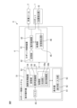
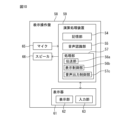
- FIG. 1 is a block diagram of a robot system having a first teaching operation panel according to an embodiment
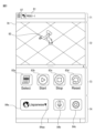
- FIG. It is an image displayed on the display unit of the teaching console. This is an image for selecting a language for speech recognition.
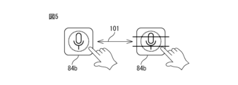
- FIG. 10 is an explanatory diagram of an icon image for executing a mute function for stopping speech recognition; It is an image in which a warning is displayed on the display section of the teaching console. It is an explanatory view explaining a term for an operator to operate by voice.
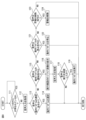
- 4 is a flow chart of control for sending a command to the robot control device by voice input. It is an image for confirming the operation displayed before executing the operation program.
- It is a block diagram of the second teaching operation panel in the embodiment.
- FIG. 11 is an explanatory diagram for explaining sounds output from the second teaching console;
- FIG. 1 A robot control system including a teaching operation panel and a teaching operation panel according to the embodiment will be described with reference to FIGS. 1 to 11.
- FIG. The robot system of this embodiment includes a work tool, a robot, and a robot control system.
- the robot control system includes a teaching operation panel and a robot control device that controls the robot.
- the worker and the robot cooperate to perform a predetermined work.
- FIG. 1 shows a perspective view of the robot system according to this embodiment.
- FIG. 2 shows a block diagram of the robot system of this embodiment.
- robot system 8 of the present embodiment performs operations based on an operation program.
- a robot system 8 includes a work tool 2 as an end effector and a robot 1 that moves the work tool 2 .
- Any work tool 2 can be attached to the robot 1 according to the work to be performed by the robot system 8 .
- a hand can be attached to the robot 1 when the robot system 8 transports a work.
- a welding torch can be attached to the robot 1 if the robot system 8 performs arc welding.
- the robot 1 of this embodiment is an articulated robot including a plurality of joints.
- the robot 1 includes a swivel base 13 supported by a base portion 14 .
- the swivel base 13 is formed to rotate with respect to the base portion 14 .
- the robot 1 includes an upper arm 11 and a lower arm 12 rotatably supported via joints. Also, the upper arm 11 rotates around a rotation axis parallel to the direction in which the upper arm 11 extends.
- the robot 1 includes a wrist 15 rotatably connected to the end of the upper arm 11 .
- Wrist 15 includes a flange 16 that is rotatably formed.
- a working tool 2 is secured to the flange 16 of the wrist 15 .
- the robot 1 of this embodiment has six joint axes, it is not limited to this form. Any robot capable of moving work tools can be employed.
- the robot 1 of this embodiment is a collaborative robot for working together with a worker.
- Collaborative robots are equipped with sensors for detecting external forces on the robot.
- a collaborative robot is formed to be able to detect an external force applied to the robot by arranging a force sensor on the base or by arranging a torque sensor on each joint axis.
- the robot controller 41 restricts the movement of the robot 1 when the robot 1 comes into contact with a worker or other object and detects an external force. For example, stop the robot or reduce the driving speed of the robot.
- components such as arms and bases are covered with a housing having a smooth surface so that they may come into contact with workers.
- the robot is not limited to a collaborative robot, and may be a robot that works alone without working together with a worker.
- the robot 1 includes a robot driving device that changes the position and posture of the robot 1.
- the robot drive includes electric motors and the like that drive components such as arms and wrists.
- the work tool 2 includes a tool driving device that drives the work tool 2 .
- the tool driving device includes an electric motor and the like for driving the work tool 2 .
- the robot 1 is provided with a position detector 18 that outputs the rotational position of the joint axis of the robot 1 .
- the position detector 18 is composed of, for example, an encoder attached to the electric motor.
- the robot controller 41 can detect the position and orientation of the robot 1 from the output of the position detector 18 .
- the robot system 8 includes a robot control system 4.
- the robot control system 4 includes a robot control device 41 including an arithmetic processing device having a CPU (Central Processing Unit) as a processor.
- the robot control device 41 constitutes a main body of the control device.
- the arithmetic processing unit has a RAM (Random Access Memory), a ROM (Read Only Memory), etc., which are connected to the CPU via a bus.
- the arithmetic processing unit of the robot control device 41 includes a storage unit 42 that stores predetermined information.
- the storage unit 42 stores information regarding control of the robot 1 and the work tool 2 .
- the storage unit 42 can be configured by a non-temporary storage medium capable of storing information.
- the storage unit 42 can be configured with a storage medium such as a volatile memory, a nonvolatile memory, a magnetic storage medium, or an optical storage medium.
- a robot motion program in which the motion of the robot is defined is stored in the storage unit 42 .
- the arithmetic processing unit of the robot control device 41 includes a motion control unit 43 that sends motion commands for the robot.
- the operation control unit 43 corresponds to a processor driven according to an operation program.
- the operation control section 43 is formed so as to be able to read information stored in the storage section 42 .
- the motion control unit 43 sends motion commands for driving the robot 1 to the electric circuit of the robot driving device based on the motion program.
- the operation control unit 43 sends an operation command for driving the work tool 2 to the electric circuit of the tool driving device based on the operation program.
- the robot 1 and work tool 2 are driven based on an operation program.
- the arithmetic processing unit of the robot control device 41 includes a processing unit 45 that processes information and performs arithmetic operations.
- the processing unit 45 includes a state detection unit 46 that detects states of the robot 1 and the work tool 2 .
- the state detector 46 detects the position and orientation of the robot 1 and the position and orientation of the work tool 2 based on the output of the position detector 18 .
- Each unit of the processing unit 45 and the state detection unit 46 corresponds to a processor driven according to a pre-generated program. Each unit functions by the processor reading the program and executing the control determined by the program.
- the robot control system 4 is a first controller for an operator to operate the robot 1, input information necessary for controlling the robot system 8, and confirm information necessary for controlling the robot system 8. , including the teaching operation panel 51.
- the teaching operation panel 51 functions as an operating device for operating the motion of the robot 1 .
- the teaching operation panel 51 is connected to the robot control device 41 via a communication device.
- the teaching operation panel 51 sends commands to the robot controller 41 that controls the operations of the robot 1 and work tool 2 .
- the teaching operation panel 51 in the present embodiment is composed of a tablet computer.
- the teaching console 51 includes a display 61 including a display panel for displaying images.
- a display panel of the display device 61 functions as a display unit 62 that displays arbitrary information.
- the display 61 of the present embodiment is formed so as to be able to detect an input operation when the operator touches the screen.
- the display device 61 of the present embodiment includes a touch panel type display panel.
- a touch panel type display panel a display panel of any type such as a resistance film type, a capacitive type, or a surface acoustic wave type can be adopted.
- the operator can perform an input operation by operating the image displayed on the display panel with a finger.
- the display 61 is formed to display images (icons) of buttons for operating the robot 1 and the work tool 2 .
- the display 61 is formed to display an image for inputting or selecting predetermined information.
- the display 61 is formed so that the pressed position can be detected by pressing the screen with a finger.
- the display device 61 is configured to determine that the icon image has been pressed by pressing the icon image displayed on the screen with a finger. For example, by pressing an icon displayed on the screen of the display panel with a finger, the operator can operate the robot corresponding to the icon.
- the display panel of the present embodiment functions as the input section 63 that detects the operator's input operation.
- the teaching operation panel is not limited to a tablet computer.
- the teaching operation panel may include a display section that displays information regarding control of the robot system, and an input section that includes input devices such as buttons, keyboards, and dials.
- the display unit can be composed of an arbitrary display panel such as a liquid crystal display panel that does not have a touch panel function.
- the teaching operation panel of this embodiment is composed of portable terminals.
- the teach console is configured to communicate with the robot controller in a wired or wireless manner.
- the mobile terminal is not limited to a tablet computer, and any mobile terminal can be used.
- the mobile terminal may be a smartphone or the like.
- the teaching operation panel 51 includes an arithmetic processing device 53 having a CPU as a processor.
- the arithmetic processing unit 53 includes a storage unit 54 that stores arbitrary information regarding the robot system.
- the storage unit 54 can be configured by a non-temporary storage medium capable of storing information.
- the storage unit 54 can be configured with a storage medium such as a volatile memory, a nonvolatile memory, a magnetic storage medium, or an optical storage medium.
- the teaching operation panel 51 in this embodiment is formed so as to be able to send commands for controlling the motions of the robot 1 and the work tool 2 to the robot control device 41 based on the voice of the operator.
- the teaching operation panel 51 includes a microphone 65 as a voice input section through which the operator inputs voice.
- the microphone 65 in this embodiment is built in the main body of the teaching operation panel 51 .
- the microphone 65 may be arranged apart from the main body of the teaching operation panel 51 .
- a headset including a microphone can be employed as the audio input unit.
- the microphone can communicate with the processing unit 53 by wireless communication. Any device that can acquire the voice of the operator can be used as the voice input unit.
- the arithmetic processing unit 53 includes a speech recognition unit 55 that recognizes speech acquired by the microphone 65 .
- the voice recognition unit 55 can recognize the voice of the worker by any method.
- the speech recognition unit 55 can convert words spoken by the operator into characters.
- the speech recognition unit 55 can estimate characters from the speech using an acoustic model after data conversion of the speech is performed by acoustic analysis. Then, it is possible to estimate words from a pre-stored dictionary and generate sentences from a language model.
- the arithmetic processing unit 53 includes a processing unit 56 that processes the result of voice recognition by the voice recognition unit 55 .
- the processing unit 56 has a transmission unit 56 a that transmits and receives data to and from the robot control device 41 .
- the transmission unit 56a sends to the robot control device 41 at least one command out of operation of the operation program of the robot 1 and cancellation of the alarm.
- the processing unit 56 acquires the operator's operation by operating the input unit 63 of the display 61 .
- the processing unit 56 has a display control unit 56b that controls the image displayed by the display unit 62 of the display device 61 .
- the display control unit 56b controls the image based on the result of voice recognition acquired by the voice recognition unit 55.
- FIG. Alternatively, the display control section 56b controls the image based on the result of the operation of the input section 63.
- Each unit of the speech recognition unit 55, the processing unit 56, the transmission unit 56a, and the display control unit 56b included in the arithmetic processing unit 53 corresponds to a processor driven according to a program generated in advance. Each unit functions by the processor reading the program and executing the control determined by the program.
- FIG. 3 shows an image displayed on the screen of the display unit in this embodiment.
- Image 70 is displayed as robotic system 8 performs a task.
- the image 70 includes an information display area 71 that displays predetermined information.
- the information display area 71 displays, for example, an image 81 of the name of the operating program, an icon 87 displaying an image displaying a menu of various functions, or the like.
- the image 70 has a robot display area 72 that displays the image of the robot 1.
- a three-dimensional image 82 of the robot 1 is displayed so as to correspond to the current posture of the robot 1 .
- Information for generating the three-dimensional image 82 of the robot is stored in advance in the storage section 54 of the teaching operation panel 51 .
- a three-dimensional model of each component of the robot such as an arm is stored in the storage unit 54 .
- Such a three-dimensional model can be created in advance by the processing unit 45 of the robot control device 41 based on the three-dimensional shape data of the robot.
- the state detection unit 46 of the robot control device 41 acquires the rotation angle of the electric motor on the joint axis from the position detector 18 and calculates the position and orientation of the robot 1 .
- the transmission unit 56 a of the teaching operation panel 51 acquires the position and posture of the robot from the robot control device 41 .
- the display control unit 56b generates an image 82 of the robot by combining the joint angles of the joints and the three-dimensional models of the constituent members.
- the worker can confirm the posture of the robot on the teaching operation panel. Also, the operator can confirm the three-dimensional position of the robot. For example, when a worker works in a position where the robot is difficult to see, the worker can confirm the position and posture of the robot from the image on the display.
- the display control unit 56b of the present embodiment can display an image 82 of the robot when the robot 1 is viewed from the viewpoint designated by the operator.
- the viewpoint for displaying the robot image 82 can be designated by the operator by touching the robot display area 72 .
- the operator can rotate the robot image 82 around the base of the robot by moving the finger while pressing the robot display area 72 with the finger. That is, the display control unit 56b rotates the robot image 82 and changes the viewpoint by performing a drag operation in the robot display area 72 .
- the operator can confirm the position and posture of the robot in an image when the robot is viewed from a desired direction.
- the display control unit 56b of the present embodiment can display the robot image 82 based on the magnification specified by the operator.
- the operator can enlarge the robot image 82 by widening the distance between the two fingers while touching the robot display area 72 with the two fingers.
- the robot image 82 can be reduced by narrowing the distance between the two fingers.
- the display control unit 56b can detect a pinch-out to enlarge the robot image 82, and can detect a pinch-in to reduce the robot image 82.
- the display control unit 56b may display the trajectory of the robot's motion.
- the storage unit 54 can store the position and orientation of the robot 1 at predetermined time intervals while the position and orientation of the robot 1 are changing.
- the display control unit 56b may display the motion path of the robot based on the position and posture of the robot at each time.
- a trajectory in which the rotation center of the surface of the flange 16 of the robot 1 moves can be adopted.
- the trajectory of the tip point of the tool can be used as the trajectory of the robot's motion.
- the image 70 displayed on the display unit 62 includes an operation area 73 that displays at least one icon of the operation of the robot operation program and the cancellation of the alarm.
- the robot control device 41 controls the robot 1 and work tool 2 based on commands from the teaching operation panel 51 .
- the display control section 56b of the teaching operation panel 51 displays the processing result on the display section 62.
- FIG. In this embodiment, the operation area 73 displays four icons 83a to 83d for the operator to operate.
- the icon 83a is an icon for selecting one operation program from a plurality of operation programs prepared in advance.
- Icon 83b is an icon for starting the selected operation program to drive robot 1 and work tool 2 .
- the icon 83c is an icon for stopping the operation program and stopping the robot 1 and the work tool 2.
- FIG. The icon 83d is an icon for canceling the alarm of the robot system 8.
- the robot control device 41 may detect an abnormality in the operation of the robot 1 or work tool 2 and issue an alarm.
- Icon 83d is an icon for canceling such an alarm.
- the operation of the robot operation program in this embodiment includes selection, activation, and stop of the robot operation program.
- the operation of the robot operation program is not limited to this form.
- the operation of the operating program may include deletion of the operating program, addition of the operating program, modification of the operating program, and the like.
- the image 70 displayed on the display unit 62 includes a voice recognition setting area 74 for making settings related to voice recognition.
- the icon 84a is an icon displaying an image for selecting a language for speech recognition.
- the icon 84b is an icon for implementing a mute function that temporarily suspends speech recognition.
- the icon 84c is an icon for making settings related to speech recognition other than the above.
- Figure 4 shows an image for selecting the language for speech recognition. 3 and 4, the operator selects a language for voice recognition by operating icon 84a in voice recognition setting area 74.
- FIG. When the operator presses a button 84aa arranged on the icon 84a, the display control section 56b displays an image 85 for selecting a language.
- image 85 In our example of image 85, we choose from English, Chinese, and Japanese. The operator can select the language used for speech recognition by pressing the desired language. The selected language is displayed on the icon 84a. Here, Japanese is selected. The terms displayed on the screen may also be switched to terms in the selected language.
- Fig. 5 shows an explanatory diagram of the operation of the icon to stop voice recognition.
- voice recognition setting area 74 has an icon 84b for stopping the function of operating by voice recognition.
- the function of performing operations by voice recognition is maintained unless the operator designates it. That is, the state of operating the teaching operation panel is maintained by the operator speaking a predetermined command sentence.
- the operator can cancel the voice recognition operation as indicated by the arrow 101.
- an image such as a strikethrough line is added to the icon 84b to indicate that the voice recognition function has stopped.
- the voice recognition operation can be resumed. Normally, the mute function icon 84b is not pressed, and the state in which operation by voice recognition is possible is maintained.
- both the touch operation of touching the screen of the display 61 and the voice operation can operate the operation program of the robot and cancel the alarm.
- the processing unit 56 of the teaching operation panel 51 transmits a command corresponding to the icon to the robot control device 41 based on the operator's operation of touching the icon.
- the operator can perform desired operations by pressing one icon in the operation area 73 .
- icons of operations necessary for daily work of the robot system 8 are collected in one operation area 73 . This configuration improves the operability for the operator.
- the operator can display an image displaying a plurality of operation programs.
- the display control unit 56b can display an image in which the names of a plurality of programs are described, like the image in which a plurality of languages are displayed as shown in FIG.
- the operator selects one operation program by pressing one of the operation programs.
- An image 81 of the name of the selected operating program is displayed in the information display area 71 .
- the transmission unit 56 a of the processing unit 56 transmits the name of the selected operation program and a command to start the operation program to the operation control unit 43 of the robot control device 41 .
- the motion control unit 43 starts driving the robot 1 and the work tool 2 based on the selected motion program.
- the transmission unit 56a sends a command to stop the operation program to the operation control unit 43 of the robot control device 41.
- the operation control unit 43 stops the currently running operation program.
- the motion control section 43 stops the work tool 2 and the robot 1 . In this manner, by pressing the icons 83a to 83c, it is possible to operate the operation program for performing the work. It is possible to select, start and stop operating programs.
- the robot control device 41 can detect that the operating state of the robot system 8 is abnormal while the robot 1 and the work tool 2 are being driven.
- the processing unit 45 of the robot control device 41 can detect an abnormality in the operating state of the robot based on the output of the position detector 18 or a sensor attached to the robot 1 for detecting an external force.
- the processing unit 45 can determine that the operating state of the robot is abnormal. In this case, the processing unit 45 can send a command to stop the robot 1 or a command to slow down the motion speed of the robot 1 to the motion control unit 43 . Alternatively, the processing unit 45 can send out an operation command for the robot 1 so as to perform an operation to avoid contact with an object.
- the processing unit 45 sends to the teaching operation panel 51 information indicating that an abnormal state has occurred and the driving state of the robot has been changed.
- the transmission section 56a of the processing section 56 of the teaching operation panel 51 receives the information that the abnormality has occurred.
- Fig. 6 shows an example of an image displayed on the display when an abnormality occurs in the operating state of the robot system.
- the display control unit 56b of the processing unit 56 of the teaching operation panel 51 displays in the information display area 71 a warning image 88 indicating that an object or person has come into contact with the robot system and stopped.
- the robot 1 is stopped and a warning is displayed on the display section 62 .
- the operator can cancel the alarm by pressing the icon 83 d in the operation area 73 .
- the operator can confirm that the abnormality has been eliminated and cancel the alarm.
- the warning image 88 displayed in the information display area 71 disappears. Then, the operator can restart the operation of the robot system by pressing the icon 83b for starting the operation.
- the operator can perform the same function as pressing the icons 83a to 83d arranged in the operation area 73 by voice operation.
- the icons 83a to 83d instead of pressing the icons 83a to 83d, it is possible to issue instructions by voice.
- FIG. 7 shows an explanatory diagram for explaining the voice operation for the operation of pressing the icon in the operation area.
- the operator utters the terms of each command after saying a predetermined term (fixed form).
- "OK FANUC” is adopted as a predetermined term.
- the voice recognition unit 55 determines that the operator's command starts by acquiring the voice "OK FANUC”.
- the voice recognition unit 55 avoids erroneously recognizing the voice. be able to. For example, it is possible to prevent erroneous judgment of a term used when a plurality of workers are talking as a command.
- the term for starting the command is not limited to this form, and any term can be adopted.
- the name of the robot (CRX) such as "ROBOT CRX” may be included.
- the operator 91a can perform the same operation as selecting an operation program by pressing the icon 83a in the operation area 73 by saying "OK FANUC Select" followed by a term related to the operation program. .
- the operator's voice command can be the file name of the operating program.
- PROG1-1 can be adopted as the name of the program.
- the speech recognition unit 55 can recognize the operation program with the file name "PROG1-1”.
- attribute information for speech recognition is added to the operating program of the present embodiment.
- the comment of the operation program is given as attribute information.
- An attribute file that accompanies the file of the action program can contain an optional comment that is different from the name of the action program.
- the name of the program corresponding to the comment may be stored in the storage unit.
- the comment can be another name for the program or a term related to the program.
- the term "junbi" is stored in the attribute file as a comment for the motion program that carries in the workpiece.
- the Japanese word "junbi" for preparing a work is defined.
- comments are used for speech recognition when selecting an operation program.
- the worker 91a pronounces "OK FANUC Select Junbi” instead of pressing the icon 83a for selecting the operation program.
- the voice recognition unit 55 recognizes the comment as "Jumbi”.
- the speech recognition unit 55 recognizes that the comment is a command to select the operation program "Jumbi”.
- the processing unit 56 selects the name of the operation program with "Jumbi" attached to the comment.
- the transmission unit 56 a of the processing unit 56 transmits the name of the selected operation program to the robot control device 41 .
- an operation program can be selected based on a predetermined comment different from the name of the program.
- the processing unit transmits a command for operating the motion program corresponding to the comment to the robot control device.
- the operator 91b can start the selected operation program by saying "OK FANUC Start” instead of pressing the icon 83b for starting the operation program arranged in the operation area 73. Also, the operator 91c can stop the currently running operation program by saying "OK FANUC Stop” instead of pressing the icon 83c for stopping the operation program.
- a voice recognition unit 55 recognizes a start or end command by voice.
- the transmission unit 56a transmits commands to the robot controller 41 to start or end the operation program.
- the worker 91d can cancel the alarm by saying "OK FANUC Reset" in the same way as when the icon 83d is pressed.
- the voice recognition unit 55 recognizes the command to cancel the warning by voice.
- the transmission unit 56a transmits to the robot control device 41 a command to cancel the alarm.
- the operator instead of operating the icon displayed on the display unit, it is possible to operate by voice.
- a voice instruction corresponding to the operation of the icon displayed on the display unit can be given.
- the operator can issue at least one of commanding the operation of the robot and canceling the alarm by voice recognition. Therefore, the operator can reduce the number of times the teaching operation panel is operated while the robot system is working. Workers do not have to interrupt their work, and work efficiency of workers is improved. In addition, it is possible to avoid work such as washing hands and removing gloves in order to operate the teaching operation panel, thereby improving work efficiency of the worker.
- the robot of this embodiment is a collaborative robot.
- a robot system and a worker simultaneously perform the same work or different work.
- the operator can switch the operation program, start the operation program, stop the operation program, and cancel the alarm without looking at or operating the teaching operation panel. . Therefore, the work efficiency of the worker is improved, and the time for collaborative work with the robot can be shortened.
- Assembling parts can be exemplified as an example of work actually performed by a worker and a robot system in cooperation.
- a robot carries a work to a predetermined work place.
- the robot maintains the position and orientation of the workpiece.
- the worker attaches the first component to the work conveyed by the robot.
- the robot maintains the position and orientation of the work after changing the orientation of the work at the work place.
- a worker attaches a different second component to the work.
- the robot transports the workpiece to a predetermined position.
- the operation program it is possible to generate in advance a first operation program including an operation command for carrying in a work and arranging it in a predetermined work place and an operation command for changing the orientation of the work. Further, it is possible to generate in advance a second operation program including an operation command for unloading the workpiece from the work place to a predetermined position.
- the worker selects the first operation program with the "Select” voice command, and starts driving the robot with the "Start” voice command.
- the robot is stopped by the voice command of "Stop”.
- the worker attaches the first component to the work.
- the operator restarts the operation according to the first operation program with the voice command of "Start”.
- the robot 1 changes the orientation of the workpiece based on the first motion program.
- the operator stops driving the robot with a voice command of "Stop”. Then, the worker attaches the second component to the work.
- the operator selects the second operation program with the "Select” voice command. Then, the robot is driven by the voice command of "Start” to carry out the work. When the work has been transported to a predetermined position, the operator stops the robot with a voice command of "Stop".
- the operator can select an operation program, execute an operation program, or stop an operation program by voice, even for complicated tasks.
- the operating program can be operated in a short time. For this reason, the work efficiency of collaborative work is improved.
- FIG. 8 shows a flow chart of the control performed by the arithmetic processing device of the teaching console panel in this embodiment.
- FIG. 8 is a flow chart of control for performing operations by voice recognition. 2, 3 and 8, at step 111, processing unit 56 determines whether icon 84b of voice recognition setting area 74 is pressed. That is, the processing unit 56 determines whether the icon 84b for enabling the mute function has been pressed. In step 111, if the icon 84b is pressed to select the mute function, this control is repeated. In step 111, if icon 84b has not been pressed, control transfers to step 112;
- the speech recognition unit 55 acquires speech from the microphone 65 .
- the voice recognition unit 55 recognizes voice. For example, the speech recognition unit 55 converts speech into characters.
- the speech recognition unit 55 determines whether the acquired speech is an operation program selection command. In this embodiment, it is determined whether or not the voice starts with "OK FANUC Select". In step 113 , if the acquired voice is a command to select an operating program, control passes to step 114 . Then, at step 114, the speech recognition unit 55 identifies the operation program designated by the speech.
- the processing unit 56 transmits the name of the selected motion program to the motion control unit 43 of the robot control device 41 .
- the display control unit 56b displays the name of the selected operation program on the image displayed by the display device 61.
- the image 70 an image 81 of the name of the program is displayed in the information display area 71.
- step 113 if the voice is not an operation program selection command, control proceeds to step 115 .
- the speech recognition unit 55 determines whether or not the speech is an operation program start command. That is, it determines whether or not the voice is "OK FANUC Start".
- step 115 if the voice is a command to start an operating program, control passes to step 116;
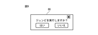
- Fig. 9 shows a confirmation image when the command to start the operating program is acquired. 8 and 9, at step 116, display control unit 56b displays a pop-up image 86 for confirming execution of the operating program. Here, an image 86 asking whether or not to execute the operation program whose comment is "Jumbi" is displayed.
- the speech recognition unit 55 acquires speech.
- the speech recognition unit 55 determines whether or not execution of the operating program has been approved. Here, when the speech recognition unit 55 acquires the speech "OK FANUC No", it is determined that the execution of the operating program has not been approved. Then, this control ends.
- step 119 the selected operating program is executed.
- the processing section 56 of the teaching operation panel 51 sends a command to start the motion program to the motion control section 43 of the robot control device 41 .
- the operation control unit 43 starts executing the selected operation program.
- an image 86 asking about execution of the operating program is displayed, but the present invention is not limited to this form.
- the operation program may be executed immediately without displaying the image 86 asking about execution of the operation program.
- step 115 control proceeds to step 121 if the voice is not an operation program start command.
- the speech recognition unit 55 determines whether the speech is an instruction to stop the operating program.
- the voice recognition unit 55 determines whether or not the voice acquired from the microphone 65 is "OK FANUC Stop". If in step 121 the voice is a command to stop the operating program, control passes to step 122 .
- step 122 the operation of the robot system is stopped.
- the processing section 56 of the teaching operation panel 51 sends a command to stop the motion program to the motion control section 43 of the robot control device 41 .
- the motion control unit 43 stops motions of the robot 1 and the work tool 2 .
- step 121 If in step 121 the voice is not a command to stop the operating program, control proceeds to step 123 .
- the voice recognition unit 55 determines whether or not the voice is an instruction to cancel the alarm. That is, it is determined whether or not the operator's voice is "OK FANUC Reset". If the operator's voice is not a command to cancel the alarm, this control is terminated. If the operator's voice is a command to clear the alarm, control passes to step 124 .
- the processing unit 56 of the teaching operation panel 51 sends a command to cancel the alarm to the motion control unit 43 of the robot control device 41 .
- the display control unit 56b performs control to erase the alarm from the image on the display 61.
- FIG. For example, the display control unit 56b executes control to turn off the warning image 88 in FIG.
- the control shown in FIG. 8 can be repeatedly performed at predetermined time intervals. Then, at least one of the operation of the robot and the cancellation of the alarm can be performed according to the voice input by the worker through the microphone.
- the operator can perform routine operations of the robot system by voice.
- the icons in the operation area for operating the robot system and the voice recognition for operating the robot are limited to operating frequently used robot operation programs and canceling alarms. . For this reason, it is possible to efficiently carry out collaborative work with the robot system by simple screen operations or simple voice command sentences.
- the operation of pressing the mute icon performs control to disable voice recognition, but the present invention is not limited to this form.
- An icon may be displayed to enable or disable voice recognition.
- FIG. 10 shows a block diagram of the second teaching operation panel arranged in the robot control system according to this embodiment.
- the second teaching operation panel 58 includes a speaker 66 as an audio output section for outputting predetermined information by audio.
- the second teaching operation panel 58 is composed of a tablet terminal having an arithmetic processing unit 59 including a CPU as a processor.
- the speaker 66 is built into the tablet terminal.
- the speaker 66 is not limited to this form, and may be arranged at a position away from the mobile terminal.
- the speaker 66 can be positioned so that the operator can hear the audio.
- the speaker may be fixed to a pedestal or the like and formed to communicate with the processing unit.
- the processing unit 57 of the arithmetic processing device 59 includes an audio output control unit 57c that controls audio output from the speaker 66, in addition to the transmission unit 56a and the display control unit 56b.
- the processing unit 57 and the audio output control unit 57c correspond to processors driven according to a predetermined program.
- the processor functions as a processing unit 57 and an audio output control unit 57c by being driven according to a program.
- the second teaching operation panel 58 can change the image displayed on the display 61 by the display control section 56 b and can output sound from the speaker 66 .
- the audio output control unit 57c of the processing unit 57 outputs audio related to the operator's voice command from the speaker 66. For example, when the operator operates the robot by voice, the voice output control unit 57c can output by voice that the operation of the robot is completed. Alternatively, when the operator inputs the operation of the robot system by voice, the voice output control unit 57c can ask by voice whether or not the operation of the robot is really allowed.
- Fig. 11 shows an explanatory diagram of the sound output from the speaker by the sound output control unit.
- control is shown in which one operator interacts with one teaching console.
- the speech recognition unit 55 recognizes that the comment is an instruction to select the operation program of "Junbi”.
- the processing unit 56 transmits to the robot control device 41 that the motion program with the comment "Junbi" has been selected.
- the voice output control section 57c of the teaching operation panel 58a outputs voice from the speaker 66 saying "Junbi is selected”.
- the voice output control section 57c of the teaching operation panel 58b outputs a voice asking which operation to perform from the speaker 66.
- operator 92b utters a command to start an operating program.
- the display control unit 56b of the teaching operation panel 58c displays an image 86 (see FIG. 9) for confirming execution of the operation program.
- the voice output control section 57c of the teaching operation panel 58c outputs voice from the speaker 66 for confirming execution of the operation program.
- the operator 92c utters a command to approve execution of the operating program in response to this voice.
- the speech recognition unit 55 recognizes consent to execute the operating program.
- the motion control section 43 of the robot control device 41 executes the motion program.
- the voice output control section 57c of the teaching operation panel 58d outputs a voice from the speaker 66 that the operation program has been executed. Then, the voice output control section 57c of the teaching operation panel 58e outputs from the speaker 66 a voice asking which operation to perform. The operator can utter a command for this question at a desired time.
- the robot system By outputting voice from the teaching operation panel, it is possible to continue work while confirming whether the operation command given by the operator is correctly recognized by voice. Also, the robot system can perform the work without error. Also, the voice output control unit may output voice to the worker so as to ask a question. With this control, the operation of the robot system can be continued as if interacting with the teaching operation panel.
Landscapes
- Engineering & Computer Science (AREA)
- Mechanical Engineering (AREA)
- Robotics (AREA)
- Multimedia (AREA)
- Human Computer Interaction (AREA)
- Physics & Mathematics (AREA)
- Audiology, Speech & Language Pathology (AREA)
- Acoustics & Sound (AREA)
- Health & Medical Sciences (AREA)
- Computational Linguistics (AREA)
- Manufacturing & Machinery (AREA)
- General Physics & Mathematics (AREA)
- Automation & Control Theory (AREA)
- Manipulator (AREA)
- Numerical Control (AREA)
Abstract
Description
4 ロボット制御システム
8 ロボットシステム
41 ロボット制御装置
43 動作制御部
51,58 教示操作盤
58a~58e 教示操作盤
54 記憶部
55 音声認識部
56,57 処理部
56b 表示制御部
57c 音声出力制御部
61 表示器
65 マイク
66 スピーカ
70,82 画像
83a~83d アイコン
Claims (8)
- ロボットの動作を制御するロボット制御装置に指令を送出する教示操作盤であって、
作業者が音声を入力する音声入力部と、
前記音声入力部が取得した音声を認識する音声認識部と、
前記音声認識部による音声の認識の結果に基づいて、ロボットの動作プログラムの操作および警報の解除のうち少なくとも1つの指令をロボット制御装置に送信する処理部と、を備える、教示操作盤。 - 作業者が画面に接触することにより入力操作を検出可能な表示器を備え、
前記表示器は、ロボットの動作プログラムの操作および警報の解除のうち少なくとも1つのアイコンを表示するように形成されており、
前記処理部は、作業者の前記アイコンに接触する操作に基づいて、前記アイコンに対応する指令をロボット制御装置に送信する、請求項1に記載の教示操作盤。 - 予め定められた情報を音声にて出力する音声出力部を備え、
前記処理部は、作業者の音声による指令に関連する音声を前記音声出力部から出力する、請求項1または2に記載の教示操作盤。 - ロボットの動作プログラムの操作は、ロボットの動作プログラムの選択、起動、および停止を含む、請求項1から3のいずれか一項に記載の教示操作盤。
- 動作プログラムには、動作プログラムの名称とは異なるコメントが属性情報として定められており、
前記音声認識部は、作業者の音声が前記コメントであると認識した場合に、処理部は、前記コメントに対応する動作プログラムの操作の指令をロボット制御装置に送信する、請求項1からの4のいずれか一項に記載の教示操作盤。 - ロボットは、作業者と共に作業を行うための協働ロボットである、請求項1から5のいずれか一項に記載の教示操作盤。
- 画像を表示する表示器を備え、
前記表示器は、現在のロボットの姿勢に対応するようにロボットの3次元の画像を表示する、請求項1に記載の教示操作盤。 - 請求項1に記載の教示操作盤と、
前記教示操作盤からの指令に基づいて、ロボットの動作を制御するロボット制御装置と、を備える、ロボット制御システム。
Priority Applications (6)
| Application Number | Priority Date | Filing Date | Title |
|---|---|---|---|
| DE112022006146.4T DE112022006146T5 (de) | 2022-02-28 | 2022-02-28 | Programmierhandgerät und Robotersteuersystem |
| CN202280092249.2A CN118742422A (zh) | 2022-02-28 | 2022-02-28 | 示教操作盘以及机器人控制系统 |
| JP2024502765A JP7817361B2 (ja) | 2022-02-28 | 2022-02-28 | 教示操作盤およびロボット制御システム |
| US18/836,756 US20250033208A1 (en) | 2022-02-28 | 2022-02-28 | Teaching operation panel and robot control system |
| PCT/JP2022/008362 WO2023162248A1 (ja) | 2022-02-28 | 2022-02-28 | 教示操作盤およびロボット制御システム |
| TW112103469A TW202335810A (zh) | 2022-02-28 | 2023-02-01 | 教示操作盤及機器人控制系統 |
Applications Claiming Priority (1)
| Application Number | Priority Date | Filing Date | Title |
|---|---|---|---|
| PCT/JP2022/008362 WO2023162248A1 (ja) | 2022-02-28 | 2022-02-28 | 教示操作盤およびロボット制御システム |
Publications (1)
| Publication Number | Publication Date |
|---|---|
| WO2023162248A1 true WO2023162248A1 (ja) | 2023-08-31 |
Family
ID=87765262
Family Applications (1)
| Application Number | Title | Priority Date | Filing Date |
|---|---|---|---|
| PCT/JP2022/008362 Ceased WO2023162248A1 (ja) | 2022-02-28 | 2022-02-28 | 教示操作盤およびロボット制御システム |
Country Status (6)
| Country | Link |
|---|---|
| US (1) | US20250033208A1 (ja) |
| JP (1) | JP7817361B2 (ja) |
| CN (1) | CN118742422A (ja) |
| DE (1) | DE112022006146T5 (ja) |
| TW (1) | TW202335810A (ja) |
| WO (1) | WO2023162248A1 (ja) |
Cited By (1)
| Publication number | Priority date | Publication date | Assignee | Title |
|---|---|---|---|---|
| US20230123443A1 (en) * | 2011-08-21 | 2023-04-20 | Asensus Surgical Europe S.a.r.l | Vocally actuated surgical control system |
Citations (4)
| Publication number | Priority date | Publication date | Assignee | Title |
|---|---|---|---|---|
| JP2002211731A (ja) * | 2001-01-12 | 2002-07-31 | Murata Mach Ltd | コンベヤ装置及び荷役方法 |
| JP2004181564A (ja) * | 2002-12-02 | 2004-07-02 | Fanuc Ltd | 産業用ロボット |
| JP2019093522A (ja) * | 2017-11-27 | 2019-06-20 | 川崎重工業株式会社 | ロボットシステム |
| JP7015416B1 (ja) * | 2021-04-30 | 2022-02-02 | ファナック株式会社 | ロボット教示システム、プログラムおよびプログラム編集装置 |
Family Cites Families (7)
| Publication number | Priority date | Publication date | Assignee | Title |
|---|---|---|---|---|
| JPH01240293A (ja) | 1988-03-23 | 1989-09-25 | Toshiba Corp | 監視装置 |
| EP0864401B1 (en) * | 1996-07-24 | 2006-02-15 | Fanuc Ltd | Jog feeding method for robots |
| JP2006068865A (ja) | 2004-09-03 | 2006-03-16 | Yaskawa Electric Corp | 産業用ロボットのプログラミングペンダント |
| PL1996376T3 (pl) * | 2006-03-03 | 2016-12-30 | Programowalny robot i interfejs użytkownika | |
| JP6517762B2 (ja) * | 2016-08-23 | 2019-05-22 | ファナック株式会社 | 人とロボットが協働して作業を行うロボットの動作を学習するロボットシステム |
| JP6674005B1 (ja) * | 2018-10-26 | 2020-04-01 | キタムラ機械株式会社 | 工作機械操作システムおよび該システムによる工作機械操作方法 |
| JP7063843B2 (ja) * | 2019-04-26 | 2022-05-09 | ファナック株式会社 | ロボット教示装置 |
-
2022
- 2022-02-28 US US18/836,756 patent/US20250033208A1/en active Pending
- 2022-02-28 WO PCT/JP2022/008362 patent/WO2023162248A1/ja not_active Ceased
- 2022-02-28 DE DE112022006146.4T patent/DE112022006146T5/de active Pending
- 2022-02-28 CN CN202280092249.2A patent/CN118742422A/zh active Pending
- 2022-02-28 JP JP2024502765A patent/JP7817361B2/ja active Active
-
2023
- 2023-02-01 TW TW112103469A patent/TW202335810A/zh unknown
Patent Citations (4)
| Publication number | Priority date | Publication date | Assignee | Title |
|---|---|---|---|---|
| JP2002211731A (ja) * | 2001-01-12 | 2002-07-31 | Murata Mach Ltd | コンベヤ装置及び荷役方法 |
| JP2004181564A (ja) * | 2002-12-02 | 2004-07-02 | Fanuc Ltd | 産業用ロボット |
| JP2019093522A (ja) * | 2017-11-27 | 2019-06-20 | 川崎重工業株式会社 | ロボットシステム |
| JP7015416B1 (ja) * | 2021-04-30 | 2022-02-02 | ファナック株式会社 | ロボット教示システム、プログラムおよびプログラム編集装置 |
Cited By (2)
| Publication number | Priority date | Publication date | Assignee | Title |
|---|---|---|---|---|
| US20230123443A1 (en) * | 2011-08-21 | 2023-04-20 | Asensus Surgical Europe S.a.r.l | Vocally actuated surgical control system |
| US11886772B2 (en) * | 2011-08-21 | 2024-01-30 | Asensus Surgical Europe S.a.r.l | Vocally actuated surgical control system |
Also Published As
| Publication number | Publication date |
|---|---|
| CN118742422A (zh) | 2024-10-01 |
| TW202335810A (zh) | 2023-09-16 |
| JP7817361B2 (ja) | 2026-02-18 |
| JPWO2023162248A1 (ja) | 2023-08-31 |
| DE112022006146T5 (de) | 2024-12-19 |
| US20250033208A1 (en) | 2025-01-30 |
Similar Documents
| Publication | Publication Date | Title |
|---|---|---|
| JP6953778B2 (ja) | 協調ロボット、コントローラ、および方法 | |
| JP3708083B2 (ja) | ロボット教示装置 | |
| JP6343353B2 (ja) | ロボットの動作プログラム生成方法及びロボットの動作プログラム生成装置 | |
| KR102567361B1 (ko) | 로봇 교시 장치 및 이를 이용한 로봇 교시 방법 | |
| JP2019188545A (ja) | ロボット制御装置 | |
| WO2019026790A1 (ja) | ロボットシステム及びその運転方法 | |
| EP3387500B1 (en) | An industrial robot and a method for controlling the robot to automatically select which program code to be executed next | |
| JP7817361B2 (ja) | 教示操作盤およびロボット制御システム | |
| JP7483420B2 (ja) | ロボットシステム、制御装置、情報処理装置、制御方法、情報処理方法、物品の製造方法、プログラム、および記録媒体 | |
| CN116921951A (zh) | 一种基于三维视觉的焊接机器人的控制方法 | |
| KR102403021B1 (ko) | 로봇 교시 장치 및 이를 이용한 로봇 교시 방법 | |
| JP2017052031A (ja) | ロボット操作装置、ロボット操作方法 | |
| JP6435940B2 (ja) | ロボット操作装置、及びロボット操作プログラム | |
| JP5429461B2 (ja) | コミュニケーションロボット開発支援装置 | |
| JP2006068865A (ja) | 産業用ロボットのプログラミングペンダント | |
| JP7553612B2 (ja) | 教示装置 | |
| JP6741968B2 (ja) | 食品処理システム | |
| US12617086B2 (en) | Teaching device, control device, and mechanical system | |
| US12569995B2 (en) | Path generation for manual robot teaching | |
| WO2023218536A1 (ja) | ロボット制御装置、ロボットシステム、及び教示装置 | |
| JP7541955B2 (ja) | ロボット用走行台車位置決定装置、該方法および該プログラム | |
| US20250026010A1 (en) | Teaching device, control device, and mechanical system | |
| WO2025046884A1 (ja) | 教示装置 | |
| CN120941374A (zh) | 焊接任务构建方法、装置、计算机设备、可读存储介质和程序产品 |
Legal Events
| Date | Code | Title | Description |
|---|---|---|---|
| 121 | Ep: the epo has been informed by wipo that ep was designated in this application |
Ref document number: 22928772 Country of ref document: EP Kind code of ref document: A1 |
|
| WWE | Wipo information: entry into national phase |
Ref document number: 2024502765 Country of ref document: JP |
|
| WWE | Wipo information: entry into national phase |
Ref document number: 18836756 Country of ref document: US |
|
| WWE | Wipo information: entry into national phase |
Ref document number: 112022006146 Country of ref document: DE |
|
| WWE | Wipo information: entry into national phase |
Ref document number: 202280092249.2 Country of ref document: CN |
|
| 122 | Ep: pct application non-entry in european phase |
Ref document number: 22928772 Country of ref document: EP Kind code of ref document: A1 |