WO2023162124A1 - ロボット制御装置、ロボット制御方法およびロボット制御プログラム - Google Patents
ロボット制御装置、ロボット制御方法およびロボット制御プログラム Download PDFInfo
- Publication number
- WO2023162124A1 WO2023162124A1 PCT/JP2022/007841 JP2022007841W WO2023162124A1 WO 2023162124 A1 WO2023162124 A1 WO 2023162124A1 JP 2022007841 W JP2022007841 W JP 2022007841W WO 2023162124 A1 WO2023162124 A1 WO 2023162124A1
- Authority
- WO
- WIPO (PCT)
- Prior art keywords
- hand
- time
- robot
- gripping
- motion
- Prior art date
- Legal status (The legal status is an assumption and is not a legal conclusion. Google has not performed a legal analysis and makes no representation as to the accuracy of the status listed.)
- Ceased
Links
Images








Classifications
-
- B—PERFORMING OPERATIONS; TRANSPORTING
- B25—HAND TOOLS; PORTABLE POWER-DRIVEN TOOLS; MANIPULATORS
- B25J—MANIPULATORS; CHAMBERS PROVIDED WITH MANIPULATION DEVICES
- B25J9/00—Program-controlled manipulators
- B25J9/16—Program controls
- B25J9/1694—Program controls characterised by use of sensors other than normal servo-feedback from position, speed or acceleration sensors, perception control, multi-sensor controlled systems, sensor fusion
- B25J9/1697—Vision controlled systems
-
- G—PHYSICS
- G05—CONTROLLING; REGULATING
- G05B—CONTROL OR REGULATING SYSTEMS IN GENERAL; FUNCTIONAL ELEMENTS OF SUCH SYSTEMS; MONITORING OR TESTING ARRANGEMENTS FOR SUCH SYSTEMS OR ELEMENTS
- G05B2219/00—Program-control systems
- G05B2219/30—Nc systems
- G05B2219/40—Robotics, robotics mapping to robotics vision
- G05B2219/40053—Pick 3-D object from pile of objects
Definitions
- the present disclosure relates to a robot control device, a robot control method, and a robot control program for controlling a robot.
- a robot that grips an object with a gripping device, that is, a hand attached to the tip of the robot, and transports the gripped object to a specified position.
- Such robots are used for assembly work in the electrical and electronic field, work for picking up workpieces from machine tools, serving work in the food field, transshipment work in the physical distribution field, and the like.
- An object gripped by the hand is hereinafter referred to as an object.
- the robot In the transport operation by the robot, first, the robot is positioned at the position of the object recognized by using the measuring device or the position previously specified by the program. Then, the hand starts to operate by executing the command. After the hand has gripped the object and a predetermined waiting time has passed, the robot starts the next operation. In such a series of gripping operations, it is desired to shorten the operation time required for the gripping operations by the robot and the hands by optimizing the timing at which the hand executes commands or the length of waiting time.
- Patent Literature 1 discloses a robot control device that starts a hand movement before the robot reaches a target position, which is the position of an object.
- the robot control device of Patent Document 1 starts the hand operation when the movement time required for the robot to reach the target position becomes shorter than the hand operation time required for the hand operation.
- the robot control device of Patent Document 1 predicts the movement time from the current position of the robot to the target position based on the robot movement command for operating the robot, and compares the predicted movement time and the hand movement time. compare.
- the robot control device of Patent Literature 1 outputs a command to the hand when the predicted movement time becomes shorter than the hand operation time.
- the time it takes for the robot to move the hand to the target position is not determined solely by the robot's motion command, but fluctuates due to the delay in the robot's motion caused by the characteristics of the robot's control system.
- the length of the delay time due to the characteristics of the robot control system varies depending on the speed or acceleration of each axis of the robot.
- the parameters of the robot control system are made variable depending on the position or posture of the robot, the length of the delay time varies depending on the position or posture of the robot.
- the travel time predicted based on the robot motion command will have an error with respect to the actual travel time. For this reason, in order to determine the timing for instructing the movement of the hand, it has been necessary for a skilled person to make adjustments for a long period of time.
- the present disclosure has been made in view of the above, and provides a robot control device that can accurately adjust the timing of instructing hand motions in order to shorten the time required for gripping motions by the robot and hands. With the goal.
- a robot control device provides a robot operation time, which is the time required for a robot hand to reach a target position, and an operation time prediction unit that predicts the hand operation time, which is the time from the point in time when the hand is held until the hand finishes gripping the object at the target position, and the predicted robot operation time and the predicted hand operation time.
- a hand movement start instructing unit that instructs the hand movement start at the timing determined based on the above.
- the operation time prediction unit predicts the robot operation time by calculation incorporating robot control system information indicating the characteristics of the robot control system.
- the robot control device has the effect of being able to accurately adjust the timing of instructing the movement of the hand in order to shorten the time required for the gripping movement of the robot and hand.
- FIG. 1 is a diagram showing a configuration example of a robot control device according to a first embodiment
- FIG. 1 is a diagram showing a configuration example of a robot control system including a robot control device according to a first embodiment
- FIG. FIG. 4 is a diagram for explaining the robot operation time predicted by the operation time prediction unit of the robot control device according to the first embodiment
- FIG. 4 is a diagram for explaining an instruction to start a hand operation and an instruction to start an operation of a robot by the robot control device according to the first embodiment
- 4 is a flow chart showing the operation procedure of the robot control device according to the first embodiment
- FIG. 11 is a diagram showing a configuration example of a robot control device according to a second embodiment
- FIG. 11 is a diagram showing a configuration example of a robot control device according to a third embodiment
- FIG. 10 is a diagram showing a configuration example of a robot control device according to a fifth embodiment
- FIG. 11 is a diagram showing a configuration example of a robot control device according to a sixth embodiment
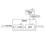
- FIG. 13 is a diagram showing a learning device and a learned model storage unit of the grasping control parameter learning unit included in the robot control device according to the sixth embodiment
- FIG. 10 is a diagram showing a configuration example of a neural network used for machine learning according to Embodiment 6
- FIG. 14 is a diagram showing an inference device and a learned model storage unit of the gripping control parameter learning unit included in the robot control device according to the sixth embodiment
- FIG. 11 is a diagram showing a configuration example of a robot control device according to a seventh embodiment
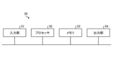
- FIG. 4 is a diagram showing a configuration example of a control circuit according to Embodiments 1 to 7
- FIG. 11 is a diagram showing a configuration example of a dedicated hardware circuit according to Embodiments 1 to 7;
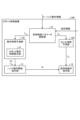
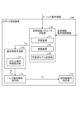
- FIG. 1 is a diagram showing a configuration example of a robot control device 10 according to a first embodiment.
- FIG. 2 is a diagram showing a configuration example of a robot control system 40 including the robot control device 10 according to the first embodiment.
- the robot control system 40 includes a robot control device 10, a robot 30, and a hand 31.
- the hand 31 is attached to the tip of an arm that constitutes the robot 30 .
- the robot controller 10 controls the robot 30 .
- the robot control system 40 grips an object by the actions of the robot 30 and the hand 31 and transports the gripped object to a designated position.
- a robot control system 40 shown in FIG. 2 retrieves an object contained in a box and transports the object to a designated location outside the box.
- a sensing device such as a vision sensor is installed as a peripheral device of the robot control system 40 .
- a sensing device recognizes the position of an object.
- the robot control device 10 acquires information on the position of the object from the sensing device, and generates a robot command based on the acquired information.
- the robot control device 10 sends a robot motion command to the drive section of the robot 30 . Illustration of the drive unit is omitted.
- the driving unit drives the robot 30 according to the robot motion command, so that the robot 30 moves according to the robot motion command.
- the hand 31 is controlled by a hand control device. Illustration of the hand control device is omitted.
- the hand 31 operates according to a hand operation command sent from the hand control device.
- the robot control system 40 may control both the robot 30 and the hand 31 without using the hand control device.
- the hand 31 has two movable parts that perform opening and closing operations.
- the hand 31 grips an object by gripping the object with two movable parts facing each other.
- the hand 31 grips the object by a closing motion in which the movable parts move toward each other.
- the hand 31 releases the gripped object by an opening operation in which the movable parts move away from each other from the state in which the gripped object is gripped.
- the hand 31 is not limited to having two movable parts. It is assumed that the number of movable parts provided in the hand 31 is not limited to two and is arbitrary. Moreover, the hand 31 is not limited to one having a movable portion.
- the hand 31 may include a portion that generates a suction force, and grip the object by causing the object to be attracted to the portion.
- the movable portion of the hand 31 is referred to as a finger portion.
- the robot control device 10 includes an operation time prediction unit 11, a familiarization time prediction unit 12, a hand movement start instruction unit 13, a post-gripping operation instruction unit 14, and a storage unit 15.
- the robot control device 10 also includes a command generator that generates a robot motion command. The illustration of the command generator is omitted.
- the operation time prediction unit 11 includes a robot operation time calculation unit 16 that calculates the robot operation time T1 and a hand operation time calculation unit 17 that calculates the hand operation time T gsp .
- the robot operating time T1 is the time required for the robot 30 to reach the target position with the hand 31 of the robot 30 .
- the hand operation time T gsp is the time from when the operation of the hand 31 is commanded to when the hand 31 finishes gripping the object at the target position.
- the motion time prediction unit 11 predicts the robot motion time T1 by calculating the robot motion time T1 using the robot motion time calculation unit 16 .
- the robot operating time calculator 16 calculates the robot remaining operating time T0 based on the robot operating time T1.
- the robot remaining operating time T0 is the time required for the robot 30 to reach the target position from an arbitrary time point after the robot 30 starts operating.
- the operation time prediction unit 11 predicts the hand operation time T gsp by calculating the hand operation time T gsp using the hand operation time calculation unit 17 .
- the operation time prediction unit 11 outputs the value of the remaining robot operation time T0 and the value of the hand operation time T gsp to the hand operation start instructing unit 13 .
- the hand operation start instructing unit 13 determines the timing for starting the operation of the hand 31 using the value of the robot remaining operation time T0 calculated based on the value of the robot operation time T1 and the value of the hand operation time T gsp . decide.
- the hand operation start instruction unit 13 instructs the hand control device to start the operation of the hand 31 at the determined timing. That is, the hand motion start instructing unit 13 instructs the hand 31 to start motion at the timing determined based on the predicted robot motion time T1 and the predicted hand motion time T gsp . Further, the hand movement start instructing section 13 outputs information indicating the time point Tk at which the movement start of the hand 31 is instructed to the post-grasping movement instruction section 14 .
- the familiarity time predicting unit 12 predicts the familiarity time Tfit .
- the familiarity time T fit is the time from when the hand 31 starts gripping the object until the hand 31 becomes familiar with the object.
- the hand 31 becoming familiar with the object means that the contact between the hand 31 and the object is stabilized so that the hand 31 can maintain the state of gripping the object even when the robot 30 moves the hand 31 .
- the familiarity time prediction unit 12 outputs the value of the predicted familiarity time T fit to the post-gripping motion instruction unit 14 .
- the length of the predicted familiarization time T fit is set as the waiting time from when the hand 31 grips the object to when the robot 30 starts the next motion.
- the post-gripping motion instruction unit 14 instructs the robot 30 to perform the next motion of gripping the object after the predicted familiarization time T fit has elapsed from the time when the hand 31 started gripping the object. do.
- Information on the position P of the object and hand motion information are input to the robot control device 10 .
- the position P is measured using a sensor such as a vision sensor.
- Information on the position P input to the robot control device 10 is updated each time the object is gripped.
- the hand motion information is information about motion of the hand 31 when gripping an object.
- the hand motion information includes values of insertion amount d, opening width w, and gripping force F gsp .
- the tip of the hand 31, that is, the tip of each finger, is inserted around the object before the closing action to grab the object is started.
- the insertion amount d represents the degree of insertion of each finger into the object.
- the fact that the tip of each finger coincides with the central position of the object means that the position of the tip of each finger in the inserting direction and the central position of the object in the inserting direction are mutually coincident.
- the insertion direction is the direction in which each finger moves due to the motion of the robot 30 prior to the closing motion.
- the opening width w is the distance between the tips of the fingers at the start of the closing motion.
- the gripping force F gsp is the force exerted by the hand 31 on the object while the hand 31 is gripping the object.
- the storage unit 15 stores robot control system information, hand property information, and object property information.
- the robot control system information is information indicating the characteristics of the robot control system that controls the drive section of the robot 30 .
- the robot control system information includes at least one of control parameter values used for feedforward control by the robot control system and control parameter values used for feedback control by the robot control system.
- a control parameter included in the robot control system information is a parameter that determines the responsiveness of the robot control system.
- Control parameters include, for example, the P (Proportional) gain, I (Integral) gain and D (Differential) gain of PID (Proportional Integral Differential) control, the time constant of the first-order lag element, or the dead time of the dead time element, It is a parameter defined in control engineering.
- the types of control parameters included in the robot control system information differ depending on the configuration of the robot control system.
- the hand characteristic information is information that indicates the operational characteristics of the hand 31 .
- the hand characteristic information includes at least one of an open/close command speed value, hand control system information, and a mechanism parameter value.
- the open/close command speed is the speed commanded by the hand control device, and is the moving speed of each finger in the opening/closing operation of the hand 31 .
- the hand control system information is information indicating characteristics of a hand control system that controls opening and closing of the hand 31 .
- the hand control system information includes values of control parameters of the hand control system.
- a mechanism parameter is a value that expresses the positional relationship of elements such as an actuator or a speed reducer that drives the hand 31 or the dimensions of each part of the finger portion of the hand 31 .
- the mechanism parameter is a value that expresses the speed reduction ratio of an actuator or speed reducer provided on the hand 31 .
- the actuators attached to the hand 31 are motors or pneumatic actuators. By using the mechanical parameters, the position of the hand 31 or the position of each finger can be calculated.
- the mechanism parameters are used to calculate the timing of contact between the hand 31 and the object or the timing of contact between the hand 31 and objects around the object.
- the finger pads of the fingers of the hand 31, which are the parts that touch the object are sometimes provided with a flexible material.
- the hand characteristic information may include information about the physical properties of the finger pulp, which is the portion of the finger portion of the hand 31 that touches the object.
- the information about the physical properties of the finger pulp includes the value of finger pulp stiffness Kh, the value of finger pulp viscosity Dh, and the like.
- the object property information is information that indicates the physical properties of the object.
- the object property information is information about the deformation of the object, and includes the value of stiffness Kw or the value of viscosity Dw.
- a position P get shown in FIG. 2 is a target position to which the tip of the hand 31 is to be reached by the motion of the robot 30 .
- Information on the position P of the object to be gripped next is input to the robot control device 10 .
- the position P get is determined based on the position P of the object and the insertion amount d.
- a position P up shown in FIG. 2 is the position of the hand 31 when the robot 30 starts to move the tip of the hand 31 to a target position.
- a sensing device which is a peripheral device of the robot control system 40, calculates the position P and insertion amount d of the object based on the result of observing the object.
- the insertion amount d calculated here is the insertion amount d in a state where the tip of the hand 31 reaches the position Pget .
- a command generation unit of the robot control device 10 generates a robot operation command based on the information on the position P of the object and the insertion amount d.
- the position P up is a user-definable position a certain distance upwards from the position P get .
- the distance between the position P up and the position P get is set such that the tip of the hand 31 does not touch objects around the object.
- the posture of the hand 31 at the position P up is set to the same posture as the posture taken by the hand 31 at the position P get .
- the robot operation command generated here is the position P get determined based on the position P of the object and the insertion amount d, and the position P up determined according to the above definition, from the position P up to the position P get .
- This is a robot motion command for causing the robot 30 to move the .
- a robot motion command is generated based on information on the position P of the object and the value of the insertion amount d, which is hand motion information.
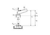
- FIG. 3 is a diagram for explaining the robot operating time T1 predicted by the operating time prediction unit 11 of the robot control device 10 according to the first embodiment.
- the robot operation time T1 is the operation time of the robot 30 when the robot 30 moves the hand 31 from the position P up to the position P get in accordance with the robot operation command.
- the starting point of the robot operating time T1 is the time when the robot 30 starts operating.
- the end point of the robot operation time T1 is the time point when the error between the position of the tip of the hand 31 and the position P get falls within a prespecified range.
- the robot operation time calculator 16 calculates the robot operation time T1 based on the robot operation command.
- the time Ta is the elapsed time from when the robot 30 started to move.
- the robot operation time calculator 16 measures the time Ta.
- the robot operating time calculator 16 calculates the remaining robot operating time T0 by subtracting the time Ta from the robot operating time T1. By calculating the robot remaining operation time T0, the operation time prediction unit 11 grasps the time required for the tip of the hand 31 to reach the target as needed.
- the robot motion time calculation unit 16 includes robot motion simulation means.
- the robot motion simulating means simulates the generation of a robot motion command and simulates the motion of the robot 30 according to the characteristics of the robot control system.
- the robot motion simulating means acquires the information on the position P of the object input to the robot control device 10 .
- the robot motion simulating means acquires the value of the insertion amount d from the hand motion information input to the robot control device 10 .
- the robot motion simulating means simulates generation of a robot motion command based on the position P and the insertion amount d of the object.
- the robot motion simulating means includes filter means for simulating the motion of the robot 30 according to the characteristics of the robot control system.
- a filter means is a mathematical model for simulating the behavior or response of a control system and a mechanical system to a command value and expressing the state of the behavior or response.
- a transfer function for example, can be used as the filter means.
- the filter means simulates the motion of the robot 30 based on the robot control system information stored in the storage unit 15 .
- the robot motion simulating means simulates the motion of the robot 30 according to the characteristics of the robot control system by passing the robot motion command through the filter means. Illustrations of the robot motion simulating means and the filtering means are omitted.
- the robot motion time calculation unit 16 predicts the actual behavior of the tip of the hand 31 based on the results of simulating the motion of the robot 30 by the robot motion simulating means.
- the robot operation time calculation unit 16 predicts the end point of the robot operation time T1 based on the predicted behavior of the hand 31, and calculates the robot operation time T1. In this manner, the robot operating time calculation unit 16 calculates the robot operating time T1 by calculation incorporating the robot control system information.
- the operating time prediction unit 11 predicts the robot operating time T1 by calculation incorporating robot control system information.
- the robot motion time calculation unit 16 is not limited to simulating the motion of the robot 30 according to the characteristics of the robot control system using the robot motion simulating means.
- the robot operation time calculation unit 16 may calculate the operation delay time Trs of the robot 30 according to the characteristics of the robot control system.
- the robot operation time calculator 16 uses an approximation function for calculating the delay time T rs based on the commanded position indicated by the robot operation command and the speed or acceleration for operating the robot 30 . By simulating the behavior of the robot control system under a plurality of operating conditions in advance, it is possible to identify the values of the parameters of the approximation function based on the results of the simulation.
- the values of the parameters of the approximation function are included in the robot control system information stored in the storage unit 15 .
- the robot operation time calculation unit 16 calculates the delay time T rs using the approximation function based on the values of the parameters of the approximation function included in the robot control system information.
- a polynomial or a neural network may be used as the approximation function.
- the robot operation time calculator 16 calculates the time T1c based on the robot operation command.
- the time T1c is the operating time of the robot 30 when the hand 31 is moved from the position P up to the position P get .
- the robot operating time calculator 16 calculates the robot operating time T1 by adding the delay time Trs to the time T1c.
- the robot operating time calculation unit 16 calculates the robot operating time T1 by calculation incorporating the robot control system information. That is, the operating time prediction unit 11 predicts the robot operating time T1 by calculation incorporating robot control system information.
- the robot motion command used to calculate the robot motion time T1 is generated based on the information on the position P of the object and the value of the insertion amount d, which is the hand motion information, as described above.
- the robot operation time calculation unit 16 calculates the robot operation time T1 by calculation incorporating the robot control system information, the information on the position P of the target object, and the hand operation information. It can be said that the operation time prediction unit 11 predicts the robot operation time T1 by calculation incorporating the robot control system information, the information on the position P of the target object, and the hand operation information.
- the hand motion time calculation unit 17 includes hand motion simulation means.
- the hand motion simulating means simulates the hand motion command and the motion of the hand 31 according to the characteristics of the hand control system.
- the hand motion simulating means acquires the value of the opening width w from the hand motion information input to the robot control device 10 .
- the hand motion simulating means acquires constants, which are mechanism parameters, from the hand characteristic information stored in the storage unit 15 .
- the hand motion simulating means calculates the stroke of the hand 31 by multiplying the value of the opening width w by a constant.
- the stroke of the hand 31 is the movement width of the tip of the hand 31 in each of the opening operation and the closing operation.
- the hand motion simulating means simulates generation of a hand motion command based on the calculated stroke.
- the hand motion simulating means includes filter means for simulating the motion of the hand 31 according to the characteristics of the hand control system.
- the filter means simulates the operation of the hand 31 based on the hand control system information among the hand characteristic information stored in the storage unit 15 .
- the hand motion simulating means simulates the motion of the hand 31 according to the characteristics of the hand control system by passing the hand motion command through the filter means.
- the illustration of the hand motion simulating means and the filtering means is omitted.
- the hand motion time calculator 17 calculates the time T gsp_o based on the result of simulating the motion of each finger of the hand 31 by the hand motion simulating means.
- the time T gsp_o is the time from when each finger starts to move until when each finger finishes its motion.
- the hand operation time calculation unit 17 calculates the hand operation time T gsp by adding the predicted value of the time required to transmit the signal that is the hand operation command to the time T gsp — o .
- As the time T gsp — o it is possible to adopt the time that elapses until the difference between the simulated finger position and the target finger position becomes equal to or less than a preset value.
- the operating time prediction unit 11 estimates the robot operating time T1 and the hand operating time T gsp using the information on the position P of the object and the values of the insertion amount d and the opening width w among the hand operating information.
- An example of predicting was explained.
- the operation time prediction unit 11 predicts the robot operation time T1 and the hand operation time T gsp using only part of the information on the position P of the object and the values of the insertion amount d and the opening width w. can be
- the motion time prediction unit 11 may not use the value of the insertion amount d in predicting the robot motion time T1 and the hand motion time Tgsp .
- the above description is an example of positioning the hand 31 by fixing the posture of each finger of the hand 31 and moving the hand 31 in a linear direction at a low speed in the vicinity of the object just before gripping.
- the insertion amount d it may be possible to improve the stability of gripping, such as making it easier to grip the vicinity of the center of gravity of the object.
- the insertion amount d is unnecessary for predicting the robot operating time T1 and the hand operating time T gsp . .
- the value of the opening width w is unnecessary for predicting the hand operating time T gsp .
- the hand operating time T gsp is a predicted value of the time required for signal transmission.
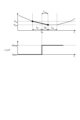
- FIG. 4 is a diagram for explaining an instruction to start operation of the hand 31 and an instruction to start operation of the robot 30 by the robot control device 10 according to the first embodiment.
- FIG. 4 shows a graph representing changes in the position of the hand 31 and a graph representing the open/closed state of the hand 31 .
- the vertical axis represents the position of the hand 31 and the horizontal axis represents time T.
- the vertical axis represents the open state or closed state
- the horizontal axis represents time T.
- the operation time prediction unit 11 Based on the value of the remaining robot operation time T0 and the value of the hand operation time T gsp , the operation time prediction unit 11 detects the timing when the value of the robot remaining operation time T0 reaches a value that satisfies T0 ⁇ T gsp . . When detecting the timing, the operation time prediction unit 11 notifies the hand operation start instructing unit 13 that the timing satisfying T0 ⁇ T gsp has arrived. Further, the operation time prediction unit 11 sends the value of the robot remaining operation time T0 at the timing and the value of the hand operation time T gsp at the timing to the hand operation start instructing unit 13 .
- the hand operation start instructing unit 13 instructs the hand control device to start the operation for gripping the object by the hand 31, ie, the closing operation, when the timing for satisfying T0 ⁇ T gsp has arrived.
- the hand operation start instruction unit 13 instructs the hand control device to start the closing operation by sending a closing operation command to the hand control device.
- the hand control device sends a hand operation command to the hand 31 in accordance with an instruction from the hand operation start instructing unit 13, whereby the hand 31 starts closing operation.
- the hand motion start instructing unit 13 sends information indicating the time Tk, for example, time information indicating the time Tk to the post-grasping motion instructing unit 14 .
- Time Tk is the time when T0 ⁇ T gsp is satisfied and the hand operation start instructing section 13 instructs the hand control device to start the closing operation.
- the hand movement start instruction section 13 sends the difference T gsp -Tp between the value of the hand movement time T gsp and the value of the elapsed time Tp to the post-gripping movement instruction section 14 at any time.
- the operating time prediction unit 11 may set the correction amount ⁇ T in advance and detect the timing at which T0 ⁇ (T gsp ⁇ T) is satisfied instead of the timing at which T0 ⁇ T gsp is satisfied. When detecting the timing, the operation time prediction unit 11 notifies the hand operation start instructing unit 13 that the timing satisfying T0 ⁇ (T gsp - ⁇ T) has arrived. Further, the operation time prediction unit 11 sends the value of the remaining robot operation time T0 at the timing, the value of the hand operation time T gsp at the timing, and the value of the correction amount ⁇ T to the hand operation start instructing unit 13 .
- the outer shape of the object is approximated to a sphere with radius Rw . It is also assumed that the object is easily deformed by receiving an external force.
- w be the opening width of the hand 31 in the open state
- wc be the opening width of the hand 31 when the hand 31 is closed so as to be able to grip an object.
- the hand 31 contacts the object when the opening width wa reaches 2Rw in the process of closing the hand 31 from the open state.
- the robot control device 10 can bring the finger into contact with the object at the timing when the motion of the robot 30 ends.
- the robot control device 10 can reduce grasping failures by preventing the fingers from contacting the object while the robot 30 is operating.
- the outer shape of the target object is approximated to a sphere, but it is also possible to approximate the outer shape of the target object to a rectangular parallelepiped.
- the success rate of gripping by the hand 31 can be improved by appropriately setting the correction amount ⁇ T based on the length Lw of the object in the direction in which the fingers face each other.
- the familiarity time prediction unit 12 holds a function for calculating the familiarity time T fit based on at least one of the hand characteristic information and the object characteristic information and the opening width w.
- the familiarity time predicting unit 12 calculates the familiarity time by a calculation that incorporates at least one of the stiffness Kh value or the viscosity Dh value that is the hand characteristic information and the stiffness Kw value or the viscosity Dw value that is the object characteristic information. Calculate Tfit .
- the familiarity time prediction unit 12 sends the value of the familiarity time T fit to the post-gripping motion instruction unit 14 .
- the conforming time prediction unit 12 can calculate the conforming time prediction unit 12 that can sufficiently deform the object. The time T fit can be calculated. As a result, the success rate of gripping by the hand 31 can be improved.
- the deformation of the object includes the case where the entire object is deformed and the case where a part of the object is deformed. Deformation of the object also includes the deformation of only the protrusions or the like formed on the surface of the object.
- the manner in which the object is deformed is not limited to a specific manner.
- the function for calculating the fitting time T fit is a tabular database representing the relationship between the opening width w, the stiffness Kw of the object, and the fitting time T fit .
- the tabular database is not limited to a two-dimensional table of opening width w and stiffness Kw, and may be a table of opening width w and familiarization time T fit for each type of object.
- the relationship between the opening width w, the stiffness Kw of the object, and the familiarization time T fit is obtained in advance by verifying the grasping motions of the robot 30 and hand 31 .
- the creation of a table will be described, taking as an example a table of the opening width w and the familiarization time T fit for each type of object.
- a plurality of objects with different sizes are prepared.
- the success or failure of gripping is determined by verifying a series of operations in which the hand 31 grips the object and the robot 30 lifts the object. Specifically, the robot 30 is caused to start lifting the object when the time T gsp +Tb has passed since the hand 31 started the closing operation, and the grasping success rate is calculated.
- the time Tb is gradually increased from 0 seconds by a predetermined step time. Verification is performed a predetermined number of times for each time T gsp +Tb with Tb different from each other, and the success rate for each time T gsp +Tb is calculated based on the number of successful grips.
- the robot 30 is stopped while the object is raised, and a vision sensor is used to determine whether the object is gripped at the position where the robot 30 is stopped.
- a force sensor may be used instead of a vision sensor to determine whether an object is being gripped. The success or failure of gripping is determined based on the output of the force sensor.
- the force sensor is attached to the wrist portion of the robot 30 that is connected to the hand 31 .
- a laser displacement gauge may be used instead of the vision sensor, and the success or failure of gripping may be determined based on the measurement result of the laser displacement gauge.
- each value of the opening width w and the familiarization time T fit at the time when the increase of the time Tb is completed is written in correspondence with each other.
- the width of the object used for verification is adopted as the value of the opening width w.
- the value of the familiarization time T fit the value of the time Tb when the success rate is equal to or higher than the threshold value is adopted.
- the value of the gripping force F gsp when the hand 31 grips the object with the opening width w set to a predetermined width w0 is Based on this, the value of the stiffness Kw of the object is derived.
- the value of the gripping force F gsp is obtained from hand motion information input to the robot control device 10 .
- each value of the stiffness Kw, the opening width w, and the familiarization time Tfit are written in correspondence with each other for each value of the stiffness Kw.
- a break-in time T fit is calculated by linear interpolation of multiple values.
- the values used for linear interpolation in this case are, for example, each value of the familiarization time T fit corresponding to each value of the opening width w, which are data points on both sides of the intermediate value.
- the stiffness Kw of the object is an intermediate value between the values shown in the table
- the familiarization time T fit for that object is the same as the values of the familiarity times T fit shown in the table.
- the values used for the linear interpolation in this case are, for example, each value of the familiarization time T fit corresponding to each value of the stiffness Kw, which are data points on both sides of the intermediate value.
- the value of the familiarization time T fit is input to the post-gripping motion instructing unit 14 .
- Information indicating the time point Tk at which the start of the gripping motion is instructed is input from the hand motion start instructing unit 13 to the post-gripping motion instructing unit 14 .
- the difference T gsp ⁇ Tp between the value of the hand motion time T gsp and the value of the elapsed time Tp is input from the hand motion start instructing section 13 to the post-grasping motion instructing section 14 at any time.
- the post-gripping motion instructing unit 14 causes the hand 31 to finish gripping the object after the predicted familiar time T fit has elapsed from the time when the hand 31 started gripping the object. It instructs the next robot 30 to start its operation.
- the driving unit drives the robot 30 according to the robot motion command, so that the robot 30 starts the next motion after gripping the object.
- the robot control device 10 may perform the processing described below.
- the robot motion time calculator 16 calculates the time T1c when the robot 30 performs one motion according to the robot motion command.
- the time T1c may be the total motion time when the robot 30 performs two consecutive motions according to the robot motion command, instead of the motion time when the robot 30 performs one motion according to the robot motion command.
- the two actions are the action of moving the hand 31 from the point Pe to the point Pe2 following the one action. .
- Two actions move the hand 31 in two consecutive trajectories Ps-Pe and Pe-Pe2.
- the robot operation time calculator 16 calculates a time T1c from when the hand 31 starts to move from the point Ps to when the hand 31 finishes moving to the point Pe2.
- the hand operation start instructing unit 13 issues a close operation command to the hand control device at time Tk when T0 ⁇ T gsp is satisfied, regardless of whether the linear movement corresponding to the insertion amount d is started or during the linear movement. send to
- FIG. 5 is a flow chart showing operation procedures of the robot control device 10 according to the first embodiment.
- step S1 the robot control device 10 acquires information on the position P of the target object and hand motion information.
- step S2 the robot control device 10 calculates the hand operation time T gsp in the hand operation time calculator 17 by calculation incorporating the hand characteristic information.
- Step S2 is a step of estimating the hand operating time T gsp .
- step S ⁇ b>3 the robot control device 10 calculates the familiarity time T fit in the familiarity time predictor 12 .
- Step S3 is a step of predicting the familiarization time T fit .
- the familiarity time prediction unit 12 calculates the familiarity time T fit by calculation incorporating at least one of the hand characteristic information and the object characteristic information and the hand motion information.
- step S4 the robot control device 10 calculates the remaining robot operation time T0 in the robot operation time calculation unit 16.
- the operation time prediction unit 11 predicts the robot operation time T1 by performing a calculation incorporating the robot control system information, the position P information, and the hand operation information before calculating the robot remaining operation time T0. .
- the robot operating time calculator 16 calculates the remaining robot operating time T0 by subtracting the elapsed time Ta from the robot operating time T1. Note that the order of step S2, step S3, and the step of predicting the robot operating time T1 is arbitrary.
- the robot control device 10 may simultaneously perform two or more of the procedures of step S2, step S3, and the step of predicting the robot operating time T1.
- step S5 the robot control device 10 determines whether or not T0 ⁇ T gsp is satisfied in the motion time prediction unit 11 . If T0 ⁇ T gsp is not satisfied (step S5, No), the robot control device 10 returns the procedure to step S4 and calculates the remaining robot operating time T0 again. If T0 ⁇ T gsp is satisfied (step S5, Yes), the robot control device 10 advances the procedure to step S6.
- step S ⁇ b>6 the robot control device 10 instructs the hand control device to start the movement of the hand 31 using the hand movement start instructing section 13 .
- Step S6 is a step of instructing the hand 31 to start operating at the timing determined based on the predicted robot operating time T1 and the predicted hand operating time T gsp .
- step S ⁇ b>7 the robot control device 10 determines whether or not the familiarization time T fit has elapsed from the time when the gripping is started in the post-gripping motion instructing section 14 . If the familiarization time T fit has not elapsed since the start of gripping (step S7, No), the robot control device 10 repeats the procedure of step S7. If the familiarization time T fit has passed since the gripping was started (step S7, Yes), the robot control device 10 advances the procedure to step S8.
- step S ⁇ b>8 the robot control device 10 uses the post-gripping motion instructing unit 14 to direct the motion of the robot 30 to be performed after the motion of gripping the object.
- Step S8 is a step of instructing the motion of the robot 30 to be performed after the motion of gripping the object after the predicted familiarization time T fit has passed since the hand 31 started gripping the object. .
- the robot control device 10 completes the operation according to the procedure shown in FIG.
- the robot control device 10 predicts the robot operation time T1 by calculation incorporating the robot control system information, thereby taking into account the delay in the operation of the robot 30 caused by the characteristics of the robot control system. , the timing for instructing the start of operation of the hand 31 can be adjusted.
- the robot control device 10 predicts the robot operation time T1 by calculation incorporating the hand operation information, so that the operation start of the hand 31 is instructed in consideration of the operation mode of the hand 31 according to the size of the object. You can adjust the timing.
- the robot control device 10 predicts the hand operation time T gsp by calculation incorporating the hand characteristic information, so that the operation characteristic of the hand 31 can be taken into consideration and the timing of instructing the start of the operation of the hand 31 can be adjusted. .
- the robot control device 10 can accurately adjust the timing of instructing the operation of the hand 31 in order to shorten the time required for the gripping operation without requiring a long time of adjustment by an expert. As described above, the robot control device 10 can accurately adjust the timing of instructing the operation of the hand 31 in order to reduce the time required for the gripping operation by the robot 30 and the hand 31 .
- the robot control device 10 predicts the familiarity time T fit and grips the object after the predicted familiarity time T fit has elapsed from the point at which the hand 31 starts gripping the object. It instructs the robot 30 to perform the next motion.
- the robot control device 10 can appropriately adjust the timing for starting the motion following the gripping motion without trial and error for adjusting the timing for starting the motion following the gripping motion.
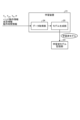
- FIG. 6 is a diagram showing a configuration example of the robot control device 10A according to the second embodiment.
- the robot control device 10A includes an operation time prediction section 11A similar to the operation time prediction section 11 described in the first embodiment. Further, the robot control device 10A is not provided with the familiarization time prediction section 12 described in the first embodiment.
- the same reference numerals are assigned to the same components as in the first embodiment, and the configuration different from the first embodiment will be mainly described.
- the post-gripping motion instructing unit 14 stores the value of the waiting time Tw from when the hand 31 grips the object to when the robot 30 starts the next motion.
- a value of the waiting time Tw is specified in advance by a program for controlling the robot 30 .
- the value of the waiting time Tw is specified in advance as a parameter value of the robot control device 10A.
- the waiting time Tw corresponds to a preset familiarization time T fit .
- Different times may be set for the waiting time Tw depending on the object. For example, when a certain type of hand 31 is used, a time Tw1 is set as the waiting time Tw when gripping an object made of metal, and a time Tw1 is set as the waiting time Tw when gripping an object made of resin. Tw2 may be set.
- the driving unit drives the robot 30 according to the robot motion command, so that the robot 30 starts the next motion after gripping the object.
- the robot control device 10A accurately adjusts the timing of instructing the gripping motion in order to shorten the time required for the gripping motion by the robot 30 and the hand 31. can do.
- the robot control device 10A can appropriately adjust the timing for starting the motion following the gripping motion without trial and error for adjusting the timing for starting the next motion after the gripping motion.
- FIG. 7 is a diagram showing a configuration example of a robot control device 10B according to the third embodiment.
- the robot control device 10B differs from the robot control device 10 according to the first embodiment in that it includes a gripping control parameter updating unit 18 . Further, the robot control device 10B includes an operation time prediction unit 11B different from the operation time prediction unit 11 described in the first embodiment, and a familiarization time prediction unit 12B different from the familiarization time prediction unit 12 described in the first embodiment. and
- the same reference numerals are assigned to the same constituent elements as in the first or second embodiment, and the configuration different from that in the first or second embodiment will be mainly described.
- the gripping control parameter updating unit 18 updates gripping control parameters.
- a gripping control parameter is a parameter for controlling a gripping operation.
- the gripping control parameters are the hand movement time T gsp and the familiarity time T fit .
- the gripping control parameter updating unit 18 acquires success/failure information indicating the result of determining whether the gripping is successful or not by verifying the motions of the robot 30 and the hand 31 .
- the success/failure information it is possible to use information indicating the result of determining the success or failure of gripping in one gripping motion, which is the previous gripping motion. Note that if the verification is performed multiple times using the same value of the gripping control parameter, the success/failure information is a value indicating the gripping success rate. A case where the same grip control parameter value is used to perform multiple verifications will be described below as an example.
- the gripping control parameter updating unit 18 outputs new hand motion information to the motion time predicting unit 11 .
- the new hand motion information is updated information about the motion of the hand 31 in the next gripping motion.
- the gripping control parameter updating unit 18 outputs information on the position P of the object to the operation time predicting unit 11B.
- the motion time prediction unit 11B includes a robot motion time calculation unit 16, like the motion time prediction unit 11 of the first embodiment.
- the operation time prediction unit 11B does not include the hand operation time calculation unit 17 described in the first embodiment.
- the gripping control parameter updating unit 18 determines the value of the hand operation time T gsp based on the success/failure information obtained by performing verification while repeatedly updating the hand operation time T gsp . Also, the gripping control parameter updating unit 18 determines the value of the familiarity time T fit based on the success/failure information acquired by performing verification while repeating updating of the familiarity time T fit .
- the gripping control parameter updating unit 18 updates the hand operation time T gsp by adjusting the hand operation time T gsp by changing the value of the hand operation time T gsp with a predetermined step size Tg.
- the gripping control parameter updating unit 18 stores the maximum value T gsp _max of the hand operation time T gsp and the minimum value T gsp _min of the hand operation time T gsp when updating the hand operation time T gsp repeatedly. Also, the gripping control parameter updating unit 18 stores the value of the step size Tg. Note that the mode of changing the value of the hand operation time T gsp in updating the hand operation time T gsp is not limited to that described in Embodiment 3, and can be changed as appropriate.
- the gripping control parameter update unit 18 updates the familiarity time Tfit by adjusting the familiarity time Tfit by changing the value of the familiarity time Tfit in a predetermined step size Tf.
- the gripping control parameter updating unit 18 stores the maximum value Tfit_max of the familiarity time Tfit and the minimum value Tfit_min of the familiarity time Tfit when repeating the updating of the familiarity time Tfit. Also, the gripping control parameter updating unit 18 stores the value of the step size Tf. Note that the mode of changing the value of the familiarity time Tfit in updating the familiarity time Tfit is not limited to that described in the third embodiment, and can be changed as appropriate.
- the gripping control parameter updating unit 18 determines the value of the hand motion time T gsp and then determines the value of the familiarity time T fit .
- the robot control device 10B fixes the value of the familiarization time T fit to the maximum value T fit _max, and sequentially increases the value of the hand operation time T gsp from the minimum value T gsp _min for each step size Tg. and the operation of the hand 31 are verified.
- the robot control device 10B determines the value of the hand operation time T gsp through such verification.
- the grip control parameter updating unit 18 sets the value of the hand operation time T gsp to the minimum value T gsp _min, and sets the value of the familiar time T fit to T gsp _min. sets the maximum value Tfit_max .
- the gripping control parameter updating unit 18 outputs the value of the hand operation time T gsp , that is, the minimum value T gsp —min to the operation time prediction unit 11B.
- the gripping control parameter updating unit 18 outputs the value of the familiarity time T fit , that is, the maximum value Tfit_max , to the familiarity time prediction unit 12B.
- the motion time prediction unit 11B in the robot motion time calculation unit 16, calculates the robot motion time T1 by incorporating the robot control system information, the position P information, and the hand motion information. Calculate The operating time prediction unit 11B predicts the robot operating time T1 by calculation incorporating robot control system information, position P information, and hand operation information. The robot operating time calculator 16 calculates the remaining robot operating time T0 by subtracting the elapsed time Ta from the robot operating time T1.
- the operation time prediction unit 11B compares the value of the remaining robot operation time T0 with the input value of the hand operation time T gsp . As in the case of the first embodiment, the operating time prediction unit 11B detects the timing when the robot remaining operating time T0 reaches a value that satisfies T0 ⁇ T gsp . When detecting the timing, the operation time prediction unit 11B notifies the hand operation start instructing unit 13 that the timing satisfying T0 ⁇ T gsp has arrived. Further, the operation time prediction unit 11B sends the value of the remaining robot operation time T0 at the timing and the value of the hand operation time T gsp at the timing to the hand operation start instructing unit 13 .
- the hand movement start instructing section 13 sends information indicating the point in time Tk, for example, time information indicating the point in time Tk to the post-grasping action instructing section 14 . Further, the hand movement start instruction section 13 transmits the difference T gsp -Tp between the value of the hand movement time T gsp input from the movement time prediction section 11B and the value of the elapsed time Tp to the post-gripping movement instruction section 14 at any time. send.
- the operation time prediction unit 11B sets the correction amount ⁇ T, and detects the timing satisfying T0 ⁇ T gsp ⁇ T instead of the timing satisfying T0 ⁇ T gsp . You can When detecting the timing, the operation time prediction unit 11B notifies the hand operation start instructing unit 13 that the timing satisfying T0 ⁇ T gsp - ⁇ T has arrived. Further, the operation time prediction unit 11B sends the value of the remaining robot operation time T0 at the timing, the value of the hand operation time T gsp at the timing, and the value of the correction amount ⁇ T to the hand operation start instructing unit 13 .
- the robot control device 10B can bring the finger into contact with the object at the timing when the motion of the robot 30 ends.
- the robot control device 10B can reduce gripping failures by preventing the fingers from contacting the object while the robot 30 is operating.
- the familiarity time prediction unit 12B outputs the value of the familiarity time T fit input from the gripping control parameter updating unit 18 to the post-gripping motion instructing unit 14 as it is.
- the post-gripping motion instructing unit 14 receives information indicating the time point Tk and the difference T gsp ⁇ Tp between the value of the hand motion time T gsp and the value of the elapsed time Tp. be.
- the driving unit drives the robot 30 according to the robot motion command, so that the robot 30 starts the next motion after gripping the object.
- the success or failure of gripping is determined by verifying a series of operations in which the hand 31 grips the object and the robot 30 lifts the object.
- the success rate of gripping is calculated by having the robot 30 and the hand 31 perform a predetermined number of motions.
- the gripping control parameter updating unit 18 receives gripping information indicating the value of the success rate.
- the gripping control parameter updating unit 18 When the success rate is equal to or higher than the preset threshold value, the gripping control parameter updating unit 18 outputs a value obtained by adding the step width Tg to the minimum value T gsp _min of the hand operating time T gsp to the operating time predicting unit 11B.
- the gripping control parameter updating unit 18 updates the hand operation time T gsp by adding the step width Tg to the value of the hand operation time T gsp .
- the robot control device 10B repeats the same operation as described above for the updated hand operation time T gsp and acquires the value of the success rate.
- the gripping control parameter updating unit 18 repeats updating of the hand operation time T gsp and increases the success rate until the success rate becomes equal to or less than the threshold value or the value of the hand operation time T gsp reaches the maximum value T gsp —max. get.
- the gripping control parameter updating unit 18, when the hand operation time T gsp reaches the maximum value T gsp _max without the success rate falling below the threshold while repeating updating and verification of the hand operation time T gsp Determine the value T gsp_max to be the value of the hand motion time T gsp .
- the gripping control parameter updating unit 18 updates the verification immediately before the verification in which the success rate becomes equal to or less than the threshold.
- the set value of the hand operation time T gsp is determined as the value of the hand operation time T gsp .
- the gripping control parameter updating unit 18 determines the value of the hand operation time T gsp based on the success/failure information obtained by verification while repeating updating of the hand operation time T gsp .
- the operating time prediction unit 11B outputs the value of the hand operating time T gsp determined by the gripping control parameter updating unit 18 based on the success/failure information as the value of the predicted hand operating time T gsp .
- the robot control device 10B performs an operation for determining the value of the familiarization time Tfit .
- the robot control device 10B fixes the value of the hand operation time T gsp to the determined value, and sequentially decreases the value of the familiar time T fit from the maximum value T fit _max for each step width Tf, thereby controlling the robot 30. and the operation of the hand 31 are verified.
- the robot control device 10B determines the value of the familiarization time T fit by such verification.
- the gripping control parameter updating unit 18 sets the maximum value Tfit_max to the familiarity time Tfit at the start of the operation for determining the value of the familiarity time Tfit .
- the gripping control parameter updating unit 18 outputs the value of the familiarity time T fit , that is, the maximum value Tfit_max , to the familiarity time prediction unit 12B. Similar to the case of determining the value of the hand operation time T gsp , also in the case of determining the value of the familiarization time T fit , the robot 30 and the hand 31 are made to perform operations a preset number of times, thereby achieving successful gripping. rate is calculated.
- the gripping control parameter updating unit 18 receives gripping information indicating the value of the success rate.
- the gripping control parameter updating unit 18 When the success rate is equal to or higher than the preset threshold value, the gripping control parameter updating unit 18 outputs a value obtained by subtracting the step width Tf from the maximum value Tfit_max of the familiarizing time Tfit to the familiarizing time predicting unit 12B.
- the gripping control parameter update unit 18 updates the familiarity time Tfit by subtracting the step width Tf from the value of the familiarity time Tfit .
- the robot control device 10B repeats the same operation as described above for the updated familiarization time T fit and acquires the calculation result of the success rate.
- the grip control parameter updating unit 18 repeats updating of the familiarity time T fit and acquires the success rate until the success rate becomes equal to or less than the threshold value or the value of the familiarity time T fit reaches the minimum value T fit _min. . If the value of the familiarization time Tfit reaches the minimum value Tfit_min without the success rate falling below the threshold while repeating the update and verification of the familiarity time Tfit , the gripping control parameter updating unit 18 updates the minimum The value Tfit_min is determined to be the value of the break-in time Tfit .
- the grip control parameter updating unit 18 sets the value at the time of the verification immediately before the verification in which the success rate becomes equal to or less than the threshold.
- the value of the familiar time T fit that has been set is determined as the value of the familiar time T fit .
- the gripping control parameter updating unit 18 determines the value of the familiarity time T fit based on the success/failure information obtained by verification while repeating updating of the familiarity time T fit .
- the familiarity time prediction unit 12B outputs the value of the familiarity time T fit determined by the gripping control parameter updating unit 18 based on the success/failure information as the value of the predicted familiarity time T fit .
- the gripping control parameter updating unit 18 updates the hand operation time T gsp and the familiarity time T fit , and determines the value of the hand operation time T gsp and the value of the familiarity time T fit based on the success/failure information.
- the gripping control parameter updating unit 18 updates the motion delay time T rs of the robot 30 instead of the hand motion time T gsp and determines the value of the delay time T rs based on the success/failure information.
- the gripping control parameters may be the delay time T rs and the familiarization time T fit , which are robot control system information.
- the gripping control parameter updating unit 18 determines the value of the delay time Trs based on the success/failure information obtained by performing verification while repeating updating of the delay time Trs .
- the operation time prediction unit 11B calculates the robot operation time T1 by calculation incorporating the value of the delay time Trs determined in the robot operation time calculation unit 16.
- FIG. The operating time prediction unit 11B predicts the robot operating time T1 by calculation incorporating the determined value of the delay time Trs .
- the gripping control parameter updating unit 18 updates the delay time T rs by adjusting the delay time T rs by changing the value of the delay time T rs with a predetermined step size Tr.
- the gripping control parameter updating unit 18 stores the maximum value T rs _max of the delay time T rs and the minimum value T rs _min of the delay time T rs when updating the delay time T rs repeatedly. Also, the gripping control parameter updating unit 18 stores the value of the step width Tr. Note that the manner in which the value of the delay time Trs is changed in updating the delay time Trs is not limited to that described in the third embodiment, and can be changed as appropriate.
- the gripping control parameter updating unit 18 determines the value of the delay time T rs and then determines the value of the familiar time T fit .
- the robot control device 10B sets the value of the familiarization time T fit to a fixed value, and changes the value of the delay time T rs from the maximum value T rs _max or the minimum value T rs _min by the step size Tr, and the robot 30 and The operation of the hand 31 is verified.
- the robot control device 10B determines the value of the delay time Trs by such verification.
- the gripping control parameter updating unit 18 sets the value of the delay time T rs to the maximum value T rs _max or the minimum value T rs _min at the start of the operation for determining the value of the delay time T rs .
- the gripping control parameter updating unit 18 outputs the value of the delay time Trs to the operation time predicting unit 11B.
- the robot operation time calculator 16 calculates the time T1c based on the robot operation command.
- the robot operating time calculator 16 calculates the robot operating time T1 by adding the delay time Trs to the time T1c.
- the robot operating time calculation unit 16 calculates the remaining robot operating time T0 by subtracting the time Ta, which is the elapsed time since the robot 30 started to operate, from the robot operating time T1.
- the gripping control parameter updating unit 18 repeats updating of the delay time T rs until the success rate becomes equal to or less than the threshold or until the value of the delay time T rs reaches the maximum value T rs _max or the minimum value T rs _min . Get the success rate with In this manner, the gripping control parameter updating unit 18 determines the value of the delay time T rs based on the success/failure information obtained by verification while repeating updating of the delay time T rs .
- the operating time prediction unit 11B predicts the robot operating time T1 by calculation incorporating the determined value of the delay time Trs .
- the robot control device 10B updates each of the hand operation time T gsp and the familiarization time T fit , and determines the value of the hand operation time T gsp and the familiarity time T based on the success/failure information obtained by verification. Determine the value of fit .
- the robot control device 10B updates each of the delay time T rs and the familiarization time T fit , which are robot control system information, and determines the value of the delay time T rs and the familiarity time T based on the success/failure information obtained by verification. Determine the value of fit .
- the robot control device 10B can improve the gripping success rate and shorten the time required for the gripping operation by the robot 30 and the hand 31 .
- the gripping control parameter updating unit 18 may update the correction amount ⁇ T and determine the value of the correction amount ⁇ T based on the success/failure information.
- the gripping control parameters include the correction amount ⁇ T.
- the gripping control parameter updating unit 18 determines the value of the correction amount ⁇ T based on the success/failure information obtained by performing verification while repeating updating of the correction amount ⁇ T.
- the gripping control parameter updating unit 18 updates the correction amount ⁇ T by adjusting the correction amount ⁇ T by changing the value of the correction amount ⁇ T in a predetermined step size.
- the operation time prediction unit 11B calculates the robot operation time T1 by calculation incorporating the determined correction amount ⁇ T in the robot operation time calculation unit 16 .
- the robot control device 10B can easily improve the success rate of gripping compared to the manual adjustment method by the user.
- the time required for the gripping operation by the hand 31 can be shortened.
- the gripping control parameter updating unit 18 may update the insertion amount d and determine the value of the insertion amount d based on the success/failure information.
- the gripping control parameters include the insertion amount d.
- the gripping control parameter updating unit 18 determines the value of the insertion amount d based on the success/failure information obtained by performing verification while repeatedly updating the insertion amount d.
- the gripping control parameter updating unit 18 updates the insertion amount d by adjusting the insertion amount d by changing the value of the insertion amount d in a predetermined step size.
- the motion time prediction unit 11B calculates the robot motion time T1 by the calculation incorporating the determined insertion amount d in the robot motion time calculation unit 16 .
- the robot control device 10B can easily improve the success rate of gripping compared to the manual adjustment method by the user, and the robot 30 and The time required for the gripping operation by the hand 31 can be shortened.
- Embodiment 4 describes a modification of the update mode of gripping control parameters in Embodiment 3.
- FIG. The operation of the robot control device 10B according to the fourth embodiment differs from that of the third embodiment in the mode of adjustment of gripping control parameters.
- the operation of the robot control device 10B according to the fourth embodiment will be described with reference to FIG.
- the same reference numerals are assigned to the same components as in the first to third embodiments, and the configuration different from the first to third embodiments will be mainly described.
- the gripping control parameters are the hand operation time T gsp and the familiarity time T fit , or the delay time T rs and the familiarity time T fit , which are robot control system information, as in the third embodiment.
- the gripping control parameter may include the correction amount ⁇ T or the insertion amount d.
- the gripping control parameters are the hand motion time T gsp and the familiarity time T fit will be described as an example.
- the robot control device 10B sets one of the value of the hand movement time T gsp and the value of the familiarization time T fit to a fixed value, and changes the other by predetermined step widths Tg and Tf. By doing so, the hand motion time T gsp or the familiarity time T fit is updated.
- the robot control device 10B uses a search method such as particle swarm optimization, Bayesian optimization, or genetic algorithm to determine the combination of the value of the hand operation time T gsp and the value of the familiarization time T fit . explore using a search method such as particle swarm optimization, Bayesian optimization, or genetic algorithm to determine the combination of the value of the hand operation time T gsp and the value of the familiarization time T fit . explore using
- a function that evaluates the shortness of operation time is used as the evaluation function used for the search.
- the operation time is the time required for the gripping operation by the robot 30 and the hand 31, and is the time from when the robot 30 starts moving to the target position to when the hand 31 finishes gripping the object. If the grasp fails, a large penalty is added to the evaluation result.
- the gripping control parameter updating unit 18 uses an evaluation function to search for the optimum combination of the hand motion time T gsp and the familiarity time T fit that can successfully grip and shorten the motion time.
- the gripping control parameter updating unit 18 terminates the search when the number of searches reaches a preset number of times. Output the combination with the value of fit .
- the gripping control parameter updating unit 18 determines the values of the delay time T rs and the familiarity time T fit that enable the grip to succeed and shorten the action time. Search for the best combination with the value using the evaluation function.
- the robot control device 10B uses an evaluation function to determine the optimum combination of the hand movement time T gsp and the familiarity time T fit that can successfully grasp and shorten the movement time. to explore.
- the robot control device 10B uses an evaluation function to search for the optimum combination of the value of the delay time T rs and the value of the familiarization time T fit that enables the grip to be successful and the operation time to be shortened.
- the robot control device 10B can improve the gripping success rate and shorten the time required for the gripping operation by the robot 30 and the hand 31 .
- FIG. 8 is a diagram showing a configuration example of a robot control device 10C according to the fifth embodiment.
- the robot control device 10C includes an operation time prediction section 11C similar to the operation time prediction section 11B described in the third embodiment. Further, the robot control device 10C is not provided with the familiarization time prediction section 12B described in the third embodiment.
- the same components as those in Embodiments 1 to 4 are denoted by the same reference numerals, and configurations different from those in Embodiments 1 to 4 will be mainly described.
- the robot control device 10C includes a gripping control parameter updating section 18C different from the gripping control parameter updating section 18 described in the third embodiment.
- the gripping control parameter is the hand operating time T gsp or the delay time T rs .
- the gripping control parameter updating unit 18C updates the hand operation time T gsp and acquires success/failure information.
- the gripping control parameter updating unit 18C determines the value of the hand operation time T gsp based on the success/failure information obtained by performing verification while repeatedly updating the hand operation time T gsp .
- the gripping control parameter updating unit 18C updates the delay time Trs , which is robot control system information, and acquires success/failure information.
- the gripping control parameter updating unit 18C determines the value of the hand operation time T gsp based on the success/failure information obtained by performing verification while repeatedly updating the hand operation time T gsp .
- the gripping control parameter updating unit 18C neither updates the familiarity time T fit nor determines the value of the familiarity time T fit .
- the operation of the robot control device 10C for determining the value of the hand motion time T gsp or the value of the delay time T rs is the same as in the case of the third embodiment.
- the robot control device 10C the gripping success rate can be improved, and the time required for the gripping operation by the robot 30 and the hand 31 can be shortened.
- the gripping control parameters may include the correction amount ⁇ T or the insertion amount d.
- Embodiment 6 will explain an example of determining the value of the gripping control parameter by machine learning.
- FIG. 9 is a diagram showing a configuration example of a robot control device 10D according to the sixth embodiment.
- the robot control device 10 ⁇ /b>D includes a gripping control parameter learning section 20 .
- the robot control device 10D does not include the gripping control parameter updating unit 18 described in the third embodiment.
- the robot control device 10D includes an operation time prediction section 11D similar to the operation time prediction section 11B described in the third embodiment.
- the robot control device 10D includes a familiarity time prediction section 12D similar to the familiarity time prediction section 12B described in the third embodiment.
- the same components as those in Embodiments 1 to 5 are denoted by the same reference numerals, and configurations different from those in Embodiments 1 to 5 will be mainly described.
- the gripping control parameter learning unit 20 includes a learning device 21 , an inference device 22 and a learned model storage unit 23 .
- the learning device 21 determines the relationship between the position P of the target object, the hand motion information, and the gripping control parameters, and the success rate of gripping is equal to or greater than a preset threshold, and the time required for the gripping motion by the robot 30 and the hand 31 Learn the relationship when the operation time is the shortest.
- the gripping control parameter is at least one of hand motion time T gsp , familiar time T fit , and delay time T rs which is robot control system information.
- the hand motion information is the value of the insertion amount d and the value of the opening width w.
- the hand motion information may include the value of the width of the object instead of the value of the opening width w.
- the learning device 21 generates a learned model indicating the relationship between the position P of the target object, the hand motion information, and the gripping control parameters.
- the learned model storage unit 23 stores learned models.
- the reasoning device 22 uses the learned model to infer values for the hand movement time T gsp , the familiarity time T fit , and the lag time T rs .
- FIG. 10 is a diagram showing the learning device 21 and the learned model storage unit 23 of the gripping control parameter learning unit 20 included in the robot control device 10D according to the sixth embodiment.
- the learning device 21 includes a data acquisition section 24 and a model generation section 25 .
- the data acquisition unit 24 receives the values of the delay time T rs , the hand motion time T gsp , and the familiarity time T fit , information on the position P, hand motion information, success/failure information, and motion time information. be.
- the success/failure information is acquired by verifying the grasping motion while updating each value of the delay time T rs , the hand motion time T gsp , and the familiarity time T fit for each combination of the position P, the insertion amount d, and the opening width w. be done.
- the success/failure information is a value indicating the gripping success rate.
- the operation time information is a value indicating the length of time from when the robot 30 starts moving to the target position to when the hand 31 finishes gripping the object. The motion time is measured when verifying the gripping motion.
- the data acquisition unit 24 uses a combination of each value of the delay time T rs , the hand movement time T gsp , and the familiarity time T fit , the position P information, the hand movement information, the success/failure information, and the movement time information. to create training data.
- the data acquisition unit 24 extracts a combination of the input delay time T rs , hand movement time T gsp , and familiarization time T fit that gives a success rate equal to or higher than the threshold and the shortest movement time. do.
- the data acquisition unit 24 obtains learning data in which the information of the position P, the hand motion information, and the combinations of the extracted values of the delay time T rs , the hand motion time T gsp , and the familiarization time T fit are associated with each other. create. Thus, the data acquisition unit 24 acquires learning data.
- the model generation unit 25 uses the learning data to generate a trained model for inferring each value of the delay time T rs , the hand movement time T gsp , and the familiarization time T fit from the position P and the hand movement information. do.
- the trained model storage unit 23 stores the generated trained models.
- supervised learning is a method of learning a feature in the learning data by giving a set of input and result data to the learning device 21 and inferring the result from the input.
- the training data includes inputs and labels that are results corresponding to the inputs.
- the position P information and the hand motion information correspond to the input, and the values of the delay time T rs , the hand motion time T gsp , and the familiarization time T fit correspond to the label.
- FIG. 11 is a diagram showing a configuration example of a neural network used for machine learning according to the sixth embodiment.
- a neural network is composed of an input layer consisting of a plurality of neurons, a hidden layer which is an intermediate layer consisting of a plurality of neurons, and an output layer consisting of a plurality of neurons.
- the intermediate layer may be one layer, or two or more layers.
- Each of the multiple values input to the input layer is multiplied by a weight and input to the intermediate layer.
- Each of the multiple values input to the intermediate layer is multiplied by a weight and output from the output layer.
- the output result output from the output layer changes according to the weight value multiplied by the input layer and the weight value multiplied by the intermediate layer.
- the neural network inputs the information of the position P and the hand motion information to the input layer, and outputs the result from the output layer so that the delay time T rs , the hand motion time T gsp , and the familiarity time T fit are approximated.
- the model generation unit 25 generates a learned model by executing the learning as described above.
- the model generation unit 25 may read the already generated learned model from the learned model storage unit 23 and update the learned model by re-learning according to the learning data.
- FIG. 12 is a diagram showing the inference device 22 and the learned model storage unit 23 of the gripping control parameter learning unit 20 included in the robot control device 10D according to the sixth embodiment.
- the inference device 22 includes a data acquisition unit 26 and an inference unit 27 .
- the data acquisition unit 26 By inputting the information of the position P and the hand motion information to the data acquisition unit 26, the data acquisition unit 26 acquires the information of the position P and the hand motion information, which are inference data.
- the inference unit 27 reads the learned model from the learned model storage unit 23 .
- the inference unit 27 outputs values of the delay time T rs , the hand motion time T gsp , and the familiarity time T fit by inputting the information of the position P and the hand motion information to the learned model.
- the gripping control parameter learning unit 20 outputs each value of the delay time Trs and the hand operation time Tgsp to the operation time prediction unit 11D.
- the gripping control parameter learning section 20 outputs the value of the familiarity time T fit to the familiarity time prediction section 12D.
- the robot operation time calculator 16 calculates the time T1c based on the robot operation command.
- the robot operating time calculator 16 calculates the robot operating time T1 by adding the delay time Trs to the time T1c.
- the robot operating time calculation unit 16 calculates the remaining robot operating time T0 by subtracting the time Ta, which is the elapsed time since the robot 30 started to operate, from the robot operating time T1.
- the motion time prediction unit 11D causes the robot motion time calculation unit 16 to calculate the robot by incorporating the robot control system information, the information on the position P of the target object, and the hand motion information. Calculate the operation time T1.
- the operation time prediction unit 11D predicts the robot operation time T1 by calculation incorporating the robot control system information, the information on the position P of the target object, and the hand operation information.
- the operation time prediction unit 11D compares the value of the remaining robot operation time T0 with the input value of the hand operation time T gsp . As in the case of the first embodiment, when the operation time prediction unit 11D detects the timing at which the value of the robot remaining operation time T0 reaches a value that satisfies T0 ⁇ T gsp , the timing that satisfies T0 ⁇ T gsp is detected. The arrival is transmitted to the hand movement start instructing section 13 . Further, the operation time prediction unit 11D sends the value of the remaining robot operation time T0 at the timing and the value of the hand operation time T gsp at the timing to the hand operation start instructing unit 13 .
- the operating time prediction unit 11D sets the correction amount ⁇ T, and instead of the timing satisfying T0 ⁇ T gsp , the timing satisfying T0 ⁇ T gsp ⁇ T may be detected.
- the robot control device 10D can bring the finger into contact with the object at the timing when the motion of the robot 30 ends.
- the robot control device 10D can reduce grasping failures by preventing the fingers from contacting the object while the robot 30 is operating.
- the familiarity time prediction unit 12D outputs the value of the familiarity time T fit input from the gripping control parameter learning unit 20 to the post-gripping motion instruction unit 14 as it is. It should be noted that the operation of each of the hand movement start instructing section 13 and the post-gripping movement instructing section 14 is the same as in the case of the first embodiment.
- Embodiment 6 the case where supervised learning is applied to the learning algorithm used by the model generation unit 25 has been described, but learning other than supervised learning may be applied to the learning algorithm.
- the model generator 25 may perform machine learning using learning algorithms such as reinforcement learning, unsupervised learning, or semi-supervised learning.
- the model generation unit 25 may perform machine learning using learning algorithms such as deep learning, genetic programming, inductive logic programming, or support vector machines.
- the learning device 21 is built in the robot control device 10D.
- the learning device 21 may be a device external to the robot control device 10D.
- the learning device 21 may be a device connected to the robot control device 10D via a network, or may be a device existing on a cloud server.
- the learning device 21 is not limited to learning the gripping control parameter values according to learning data created for one robot control device 10D.
- the learning device 21 may learn the value of the gripping control parameter according to learning data created for a plurality of robot control devices 10D.
- the learning device 21 may acquire learning data from a plurality of robot control devices 10D used at the same location, or acquire learning data from a plurality of robot control devices 10D used at different locations. You can The learning data may be acquired from the robot controllers 10D that operate independently of each other at multiple locations. After starting acquisition of learning data from a plurality of robot control devices 10D, a new robot control device 10D may be added as a target for acquiring learning data. Also, after starting acquisition of learning data from a plurality of robot control devices 10D, some of the plurality of robot control devices 10D may be excluded from targets for which learning data is acquired.
- the learning device 21 that has learned about one robot control device 10D may also learn about other robot control devices 10D other than the robot control device 10D.
- the learning device 21 can update the learned model by re-learning the other robot control device 10D.
- the learning device 21 learns the relationship between the position P of the object, the hand motion information, and at least one of the values of the hand motion time T gsp , the familiar time T fit , and the delay time T rs . Good luck.
- the inference device 22 uses the trained model to infer at least one of the hand movement time T gsp , the familiarity time T fit , and the delay time T rs from the position P of the object and the hand movement information. do.
- the hand motion information input to the learning device 21 should include at least one of the value of the insertion amount d and the value of the opening width w.
- the hand motion information input to the learning device 21 may include speed or acceleration information when the robot 30 is moved by the insertion amount d at the specified position instead of the insertion amount d.
- the robot control device 10D is configured such that the relationship between the position P of the target object, the hand motion information, and the gripping control parameters is such that the gripping success rate is equal to or higher than a preset threshold value, and the robot 30 and The relationship when the operation time, which is the time required for the gripping operation by the hand 31, is the shortest is learned.
- the robot control device 10D infers values of gripping control parameters from the position P of the object and the hand motion information using the learned model.
- the robot control device 10 ⁇ /b>D can improve the gripping success rate and shorten the time required for the gripping operation by the robot 30 and the hand 31 .
- FIG. 13 is a diagram showing a configuration example of a robot control device 10E according to the seventh embodiment.
- the robot control device 10E includes a gripping control parameter learning unit 20, like the robot control device 10D according to the sixth embodiment.
- the robot control device 10E includes an operation time prediction section 11E similar to the operation time prediction section 11D described in the sixth embodiment. Further, the robot control device 10E is not provided with the familiarization time prediction section 12D described in the sixth embodiment.
- the same components as those in Embodiments 1 to 6 are denoted by the same reference numerals, and configurations different from those in Embodiments 1 to 6 will be mainly described.
- the gripping control parameter is at least one of the hand operation time T gsp and the delay time T rs which is robot control system information.
- the learning device 21 learns the relationship between the position P of the object, the hand motion information, and at least one of the values of the hand motion time T gsp and the delay time T rs .
- the value of the familiarization time T fit is not input to the learning device 21 .
- the inference device 22 infers values of the hand movement time T gsp and the delay time T rs using the learned model. The inference device 22 does not infer the value of the familiarization time T fit .
- the robot control device 10E determines that the relationship between the position P of the target object, the hand motion information, and the gripping control parameter has a gripping success rate equal to or higher than a preset threshold value, and The relationship is learned when the operation time, which is the time required for the gripping operation by the robot 30 and the hand 31, is the shortest.
- the robot control device 10E uses the learned model to infer the value of the gripping control parameter from the position P and the hand motion information. Thereby, the robot control device 10 ⁇ /b>E can improve the grasping success rate and shorten the time required for the grasping operation by the robot 30 and the hand 31 .
- the robot controllers 10, 10A, 10B, 10C, 10D and 10E are realized by processing circuits.
- the processing circuitry may be circuitry in which a processor executes software, or it may be dedicated circuitry.
- FIG. 14 is a diagram showing a configuration example of the control circuit 50 according to the first to seventh embodiments.
- the control circuit 50 comprises an input section 51 , a processor 52 , a memory 53 and an output section 54 .
- the input unit 51 is an interface circuit that receives data input from outside the control circuit 50 and provides it to the processor 52 .
- the output unit 54 is an interface circuit that sends data from the processor 52 or memory 53 to the outside of the control circuit 50 .
- the processing circuit is the control circuit 50 shown in FIG. 14, the processor 52 reads out and executes the robot control program stored in the memory 53 to control each of the robot control devices 10, 10A, 10B, 10C, 10D and 10E.
- a component is realized.
- the robot control program is a program corresponding to each component of the robot control devices 10, 10A, 10B, 10C, 10D and 10E.
- the processor 52 outputs data such as calculation results to the volatile memory of the memory 53 .
- Memory 53 is also used as temporary memory in each process performed by processor 52 .
- the processor 52 may output data such as calculation results to the memory 53 for storage, or may store data such as calculation results in an auxiliary storage device via the volatile memory of the memory 53 .
- a function of storing information in each component
- the processor 52 is a CPU (Central Processing Unit, also referred to as a central processing unit, processing unit, arithmetic unit, microprocessor, microcomputer, processor, or DSP (Digital Signal Processor)).
- the memory 53 is a non-volatile memory such as RAM (Random Access Memory), ROM (Read Only Memory), flash memory, EPROM (Erasable Programmable Read Only Memory), EEPROM (registered trademark) (Electrically Erasable Programmable Read Only Memory), etc.
- RAM Random Access Memory
- ROM Read Only Memory
- flash memory EPROM (Erasable Programmable Read Only Memory), EEPROM (registered trademark) (Electrically Erasable Programmable Read Only Memory), etc.
- EEPROM registered trademark
- a volatile semiconductor memory a magnetic disk, a flexible disk, an optical disk, a compact disk, a mini disk, a DVD (Digital Versatile Disc), or the like.
- FIG. 14 is an example of hardware when each component is implemented by a general-purpose processor 52 and memory 53, each component may be implemented by a dedicated hardware circuit.
- FIG. 15 is a diagram showing a configuration example of the dedicated hardware circuit 55 according to the first to seventh embodiments.
- the dedicated hardware circuit 55 comprises an input section 51 , an output section 54 and a processing circuit 56 .
- the processing circuit 56 is a single circuit, a composite circuit, a programmed processor, a parallel programmed processor, an ASIC (Application Specific Integrated Circuit), an FPGA (Field Programmable Gate Array), or a circuit combining these. Each component may be realized by combining the control circuit 50 and the hardware circuit 55 .
- the robot control program may be stored in a recording medium such as a CD (Compact Disc)-ROM, DVD-ROM, etc., and the recording medium may be provided to implement each embodiment.
- a recording medium such as a CD (Compact Disc)-ROM, DVD-ROM, etc.
- each embodiment is an example of the content of the present disclosure.
- the configuration of each embodiment can be combined with another known technique. Configurations of respective embodiments may be combined as appropriate. A part of the configuration of each embodiment can be omitted or changed without departing from the gist of the present disclosure.
- 10, 10A, 10B, 10C, 10D, 10E Robot control device, 11, 11A, 11B, 11C, 11D, 11E: Operation time prediction unit, 12, 12B, 12D: Familiarization time prediction unit, 13: Hand operation start instruction unit, 14: Grasping Post-operation instruction unit 15 storage unit 16 robot operation time calculation unit 17 hand operation time calculation unit 18, 18C grasp control parameter update unit 20 grasp control parameter learning unit 21 learning device 22 reasoning device 23 learned Model storage unit, 24, 26 Data acquisition unit, 25 Model generation unit, 27 Inference unit, 30 Robot, 31 Hand, 40 Robot control system, 50 Control circuit, 51 Input unit, 52 Processor, 53 Memory, 54 Output unit, 55 Hardware circuit, 56 processing circuit.
Landscapes
- Engineering & Computer Science (AREA)
- Robotics (AREA)
- Mechanical Engineering (AREA)
- Manipulator (AREA)
Abstract
Description
図1は、実施の形態1にかかるロボット制御装置10の構成例を示す図である。図2は、実施の形態1にかかるロボット制御装置10を含むロボット制御システム40の構成例を示す図である。
図6は、実施の形態2にかかるロボット制御装置10Aの構成例を示す図である。ロボット制御装置10Aは、実施の形態1で説明した動作時間予測部11と同様の動作時間予測部11Aを備える。また、ロボット制御装置10Aには、実施の形態1で説明したなじみ時間予測部12は備えられていない。実施の形態2では、上記の実施の形態1と同一の構成要素には同一の符号を付し、実施の形態1とは異なる構成について主に説明する。
図7は、実施の形態3にかかるロボット制御装置10Bの構成例を示す図である。ロボット制御装置10Bは、把持制御パラメータ更新部18を備える点が、実施の形態1にかかるロボット制御装置10とは異なる。また、ロボット制御装置10Bは、実施の形態1で説明した動作時間予測部11とは異なる動作時間予測部11Bと、実施の形態1で説明したなじみ時間予測部12とは異なるなじみ時間予測部12Bとを備える。実施の形態3では、上記の実施の形態1または2と同一の構成要素には同一の符号を付し、実施の形態1または2とは異なる構成について主に説明する。
実施の形態4では、実施の形態3における把持制御パラメータの更新の態様の変形例について説明する。実施の形態4にかかるロボット制御装置10Bの動作は、把持制御パラメータの調整の態様が実施の形態3とは異なる。ここでは、図7を参照して、実施の形態4にかかるロボット制御装置10Bの動作を説明する。実施の形態4では、上記の実施の形態1から3と同一の構成要素には同一の符号を付し、実施の形態1から3とは異なる構成について主に説明する。
図8は、実施の形態5にかかるロボット制御装置10Cの構成例を示す図である。ロボット制御装置10Cは、実施の形態3で説明した動作時間予測部11Bと同様の動作時間予測部11Cを備える。また、ロボット制御装置10Cには、実施の形態3で説明したなじみ時間予測部12Bは備えられていない。実施の形態5では、上記の実施の形態1から4と同一の構成要素には同一の符号を付し、実施の形態1から4とは異なる構成について主に説明する。
実施の形態6では、機械学習により把持制御パラメータの値を決定する例について説明する。図9は、実施の形態6にかかるロボット制御装置10Dの構成例を示す図である。ロボット制御装置10Dは、把持制御パラメータ学習部20を備える。ロボット制御装置10Dには、実施の形態3で説明した把持制御パラメータ更新部18は備えられていない。ロボット制御装置10Dは、実施の形態3で説明した動作時間予測部11Bと同様の動作時間予測部11Dを備える。ロボット制御装置10Dは、実施の形態3で説明したなじみ時間予測部12Bと同様のなじみ時間予測部12Dを備える。実施の形態6では、上記の実施の形態1から5と同一の構成要素には同一の符号を付し、実施の形態1から5とは異なる構成について主に説明する。
図13は、実施の形態7にかかるロボット制御装置10Eの構成例を示す図である。ロボット制御装置10Eは、実施の形態6にかかるロボット制御装置10Dと同様に、把持制御パラメータ学習部20を備える。ロボット制御装置10Eは、実施の形態6で説明した動作時間予測部11Dと同様の動作時間予測部11Eを備える。また、ロボット制御装置10Eには、実施の形態6で説明したなじみ時間予測部12Dは備えられていない。実施の形態7では、上記の実施の形態1から6と同一の構成要素には同一の符号を付し、実施の形態1から6とは異なる構成について主に説明する。
Claims (13)
- ロボットのハンドを前記ロボットが目的位置に到達させるまでに要する時間であるロボット動作時間と、前記ハンドの動作が指令された時点から前記目的位置において前記ハンドが対象物を把持する動作を終えるまでの時間であるハンド動作時間とを予測する動作時間予測部と、
予測された前記ロボット動作時間と予測された前記ハンド動作時間とに基づいて決定されたタイミングでの前記ハンドの動作開始を指示するハンド動作開始指示部と、を備え、
前記動作時間予測部は、前記ロボットの制御系の特性を示すロボット制御系情報を組み入れた計算により前記ロボット動作時間を予測することを特徴とするロボット制御装置。 - 前記動作時間予測部は、前記ロボット制御系情報と、前記対象物の位置の情報と、前記対象物を把持するときの前記ハンドの動作についての情報であるハンド動作情報とを組み入れた計算により前記ロボット動作時間を予測することを特徴とする請求項1に記載のロボット制御装置。
- 前記動作時間予測部は、前記ハンドの制御系の特性または前記ハンドを構成する機構の特性を示すハンド特性情報を組み入れた計算により前記ハンド動作時間を予測することを特徴とする請求項1または2に記載のロボット制御装置。
- 前記ロボットおよび前記ハンドによる把持動作を制御するための把持制御パラメータである前記ハンド動作時間を更新させ、かつ、前記ロボットおよび前記ハンドの動作の検証により把持の成否を判定した結果を示す成否情報を取得する把持制御パラメータ更新部を備え、
前記把持制御パラメータ更新部は、前記ハンド動作時間の更新を繰り返しながら前記検証が行われて取得された前記成否情報に基づいて前記ハンド動作時間の値を決定し、
前記動作時間予測部は、前記成否情報に基づいて決定された前記ハンド動作時間の値を、予測された前記ハンド動作時間の値として出力することを特徴とする請求項1から3のいずれか1つに記載のロボット制御装置。 - 前記ロボットおよび前記ハンドによる把持動作を制御するための把持制御パラメータである前記ロボット制御系情報を更新させ、かつ、前記ロボットおよび前記ハンドの動作の検証により把持の成否を判定した結果を示す成否情報を取得する把持制御パラメータ更新部を備え、
前記把持制御パラメータ更新部は、前記ハンド動作時間の更新を繰り返しながら前記検証が行われて取得された前記成否情報に基づいて前記ロボット制御系情報を決定し、
前記動作時間予測部は、前記成否情報に基づいて決定された前記ロボット制御系情報を組み入れた計算により前記ロボット動作時間を予測することを特徴とする請求項1から3のいずれか1つに記載のロボット制御装置。 - 前記対象物の位置の情報と、前記ハンドの動作についての情報であって前記対象物についての情報に基づいて得られるハンド動作情報と、前記ハンド動作時間および前記ロボット制御系情報の少なくとも1つである把持制御パラメータとの関係であって、把持の成功率があらかじめ定められた閾値以上、かつ、前記対象物を把持する把持動作に要する時間である動作時間が最短となるときにおける前記関係を学習する把持制御パラメータ学習部を備えることを特徴とする請求項1から3のいずれか1つに記載のロボット制御装置。
- 前記ハンドが前記対象物の把持を開始してから前記ハンドが前記対象物になじむまでの時間であるなじみ時間を予測するなじみ時間予測部と、
前記ハンドが前記対象物の把持を開始した時点から、予測された前記なじみ時間が経過した後に、前記対象物を把持する動作の次に行われる前記ロボットの動作を指示する把持後動作指示部と、を備えることを特徴とする請求項1に記載のロボット制御装置。 - 前記なじみ時間予測部は、前記ハンドの制御系の特性または前記ハンドの動作特性を示すハンド特性情報、および前記対象物の特性を示す対象物特性情報の少なくとも一方と、前記ハンドの動作についての情報であって前記対象物についての情報に基づいて得られるハンド動作情報とを組み入れた計算により前記なじみ時間を予測することを特徴とする請求項7に記載のロボット制御装置。
- 前記ロボットおよび前記ハンドによる把持動作を制御するための把持制御パラメータである前記ハンド動作時間および前記なじみ時間の各々を更新させ、かつ、前記ロボットおよび前記ハンドの動作の検証により把持の成否を判定した結果を示す成否情報を取得する把持制御パラメータ更新部を備え、
前記把持制御パラメータ更新部は、前記ハンド動作時間の更新を繰り返しながら前記検証が行われて取得された前記成否情報に基づいて前記ハンド動作時間の値を決定し、かつ、前記なじみ時間の更新を繰り返しながら前記検証が行われて取得された前記成否情報に基づいて前記なじみ時間の値を決定し、
前記動作時間予測部は、前記成否情報に基づいて決定された前記ハンド動作時間の値を、予測された前記ハンド動作時間の値として出力し、
前記なじみ時間予測部は、前記成否情報に基づいて決定された前記なじみ時間の値を、予測された前記なじみ時間の値として出力することを特徴とする請求項7または8に記載のロボット制御装置。 - 前記ロボットおよび前記ハンドによる把持動作を制御するための把持制御パラメータである前記ロボット制御系情報および前記なじみ時間の各々を更新させ、かつ、前記ロボットおよび前記ハンドの動作の検証により把持の成否を判定した結果を示す成否情報を取得する把持制御パラメータ更新部を備え、
前記把持制御パラメータ更新部は、前記ロボット制御系情報の更新を繰り返しながら前記検証が行われて取得された前記成否情報に基づいて前記ロボット制御系情報を決定し、かつ、前記なじみ時間の更新を繰り返しながら前記検証が行われて取得された前記成否情報に基づいて前記なじみ時間を決定し、
前記動作時間予測部は、前記成否情報に基づいて決定された前記ロボット制御系情報を組み入れた計算により前記ロボット動作時間を予測し、
前記なじみ時間予測部は、前記成否情報に基づいて決定された前記なじみ時間の値を、予測された前記なじみ時間の値として出力することを特徴とする請求項7または8に記載のロボット制御装置。 - 前記対象物の位置と、前記ハンドの動作についての情報であって前記対象物についての情報に基づいて得られるハンド動作情報と、前記ハンド動作時間、前記なじみ時間、および前記ロボット制御系情報の少なくとも1つである把持制御パラメータとの関係であって、把持の成功率があらかじめ設定された閾値以上、かつ、前記対象物を把持する把持動作に要する時間である動作時間が最短となるときにおける前記関係を学習する把持制御パラメータ学習部を備えることを特徴とする請求項7または8に記載のロボット制御装置。
- ロボットのハンドを前記ロボットが目的位置に到達させるまでに要する時間であるロボット動作時間を、前記ロボットの制御系の特性を示すロボット制御系情報を組み入れた計算により予測するステップと、
前記ハンドの動作が指令されたときから前記目的位置において前記ハンドが対象物を把持する動作を終えるまでの時間であるハンド動作時間を予測するステップと、
予測された前記ロボット動作時間と予測された前記ハンド動作時間とに基づいて決定されたタイミングでの前記ハンドの動作開始を指示するステップと、を含むことを特徴とするロボット制御方法。 - ロボットのハンドを前記ロボットが目的位置に到達させるまでに要する時間であるロボット動作時間を、前記ロボットの制御系の特性を示すロボット制御系情報を組み入れた計算により予測するステップと、
前記ハンドの動作が指令されたときから前記目的位置において前記ハンドが対象物を把持する動作を終えるまでの時間であるハンド動作時間を予測するステップと、
予測された前記ロボット動作時間と予測された前記ハンド動作時間とに基づいて決定されたタイミングでの前記ハンドの動作開始を指示するステップと、をコンピュータシステムに実行させることを特徴とするロボット制御プログラム。
Priority Applications (4)
| Application Number | Priority Date | Filing Date | Title |
|---|---|---|---|
| CN202280092080.0A CN118715095A (zh) | 2022-02-25 | 2022-02-25 | 机器人控制装置、机器人控制方法及机器人控制程序 |
| PCT/JP2022/007841 WO2023162124A1 (ja) | 2022-02-25 | 2022-02-25 | ロボット制御装置、ロボット制御方法およびロボット制御プログラム |
| JP2022544412A JP7237249B1 (ja) | 2022-02-25 | 2022-02-25 | ロボット制御装置、ロボット制御方法およびロボット制御プログラム |
| DE112022006727.6T DE112022006727B4 (de) | 2022-02-25 | 2022-02-25 | Robotersteuervorrichtung, robotersteuerverfahren und computerspeicherlesbares medium |
Applications Claiming Priority (1)
| Application Number | Priority Date | Filing Date | Title |
|---|---|---|---|
| PCT/JP2022/007841 WO2023162124A1 (ja) | 2022-02-25 | 2022-02-25 | ロボット制御装置、ロボット制御方法およびロボット制御プログラム |
Publications (1)
| Publication Number | Publication Date |
|---|---|
| WO2023162124A1 true WO2023162124A1 (ja) | 2023-08-31 |
Family
ID=85503246
Family Applications (1)
| Application Number | Title | Priority Date | Filing Date |
|---|---|---|---|
| PCT/JP2022/007841 Ceased WO2023162124A1 (ja) | 2022-02-25 | 2022-02-25 | ロボット制御装置、ロボット制御方法およびロボット制御プログラム |
Country Status (4)
| Country | Link |
|---|---|
| JP (1) | JP7237249B1 (ja) |
| CN (1) | CN118715095A (ja) |
| DE (1) | DE112022006727B4 (ja) |
| WO (1) | WO2023162124A1 (ja) |
Citations (6)
| Publication number | Priority date | Publication date | Assignee | Title |
|---|---|---|---|---|
| JP2015182145A (ja) * | 2014-03-20 | 2015-10-22 | キヤノン株式会社 | ロボットシステムの制御方法、およびロボットシステム |
| JP2015229205A (ja) * | 2014-06-04 | 2015-12-21 | 株式会社Taiyo | 電動グリッパ装置 |
| JP2018167361A (ja) * | 2017-03-30 | 2018-11-01 | 株式会社安川電機 | ロボット動作指令生成方法、ロボット動作指令生成装置及びコンピュータプログラム |
| JP2020062730A (ja) * | 2018-10-18 | 2020-04-23 | キヤノン株式会社 | ロボット制御方法、ロボット装置、プログラム、記録媒体および物品の製造方法 |
| JP2020129620A (ja) * | 2019-02-08 | 2020-08-27 | ヤマハ発動機株式会社 | 基板作業装置 |
| JP2020157398A (ja) * | 2019-03-25 | 2020-10-01 | ファナック株式会社 | ロボット装置の動作を調整する動作調整装置およびロボット装置の動作を調整する動作調整方法 |
Family Cites Families (6)
| Publication number | Priority date | Publication date | Assignee | Title |
|---|---|---|---|---|
| JP2000000787A (ja) | 1998-06-11 | 2000-01-07 | Meidensha Corp | ロボット制御装置 |
| JP4541218B2 (ja) | 2005-04-08 | 2010-09-08 | 三菱電機株式会社 | 指令生成装置 |
| JP5623358B2 (ja) * | 2011-09-06 | 2014-11-12 | 三菱電機株式会社 | ワーク取り出し装置 |
| JP2015112654A (ja) * | 2013-12-10 | 2015-06-22 | セイコーエプソン株式会社 | 制御装置、ロボット、教示データ生成方法及びロボットシステム |
| JP6042860B2 (ja) | 2014-12-02 | 2016-12-14 | ファナック株式会社 | ロボットを用いて物品を移送する物品移送装置及び物品移送方法 |
| JP6514171B2 (ja) | 2016-09-27 | 2019-05-15 | ファナック株式会社 | 最適な物品把持経路を学習する機械学習装置、及び機械学習方法 |
-
2022
- 2022-02-25 DE DE112022006727.6T patent/DE112022006727B4/de active Active
- 2022-02-25 WO PCT/JP2022/007841 patent/WO2023162124A1/ja not_active Ceased
- 2022-02-25 JP JP2022544412A patent/JP7237249B1/ja active Active
- 2022-02-25 CN CN202280092080.0A patent/CN118715095A/zh active Pending
Patent Citations (6)
| Publication number | Priority date | Publication date | Assignee | Title |
|---|---|---|---|---|
| JP2015182145A (ja) * | 2014-03-20 | 2015-10-22 | キヤノン株式会社 | ロボットシステムの制御方法、およびロボットシステム |
| JP2015229205A (ja) * | 2014-06-04 | 2015-12-21 | 株式会社Taiyo | 電動グリッパ装置 |
| JP2018167361A (ja) * | 2017-03-30 | 2018-11-01 | 株式会社安川電機 | ロボット動作指令生成方法、ロボット動作指令生成装置及びコンピュータプログラム |
| JP2020062730A (ja) * | 2018-10-18 | 2020-04-23 | キヤノン株式会社 | ロボット制御方法、ロボット装置、プログラム、記録媒体および物品の製造方法 |
| JP2020129620A (ja) * | 2019-02-08 | 2020-08-27 | ヤマハ発動機株式会社 | 基板作業装置 |
| JP2020157398A (ja) * | 2019-03-25 | 2020-10-01 | ファナック株式会社 | ロボット装置の動作を調整する動作調整装置およびロボット装置の動作を調整する動作調整方法 |
Also Published As
| Publication number | Publication date |
|---|---|
| JP7237249B1 (ja) | 2023-03-10 |
| CN118715095A (zh) | 2024-09-27 |
| DE112022006727B4 (de) | 2026-04-23 |
| DE112022006727T5 (de) | 2024-12-19 |
| JPWO2023162124A1 (ja) | 2023-08-31 |
Similar Documents
| Publication | Publication Date | Title |
|---|---|---|
| CN112045675B (zh) | 机器人设备控制器、机器人设备系统及其控制方法 | |
| Nicolis et al. | Human intention estimation based on neural networks for enhanced collaboration with robots | |
| CN113748597B (zh) | 电动机控制装置 | |
| JP7699660B2 (ja) | 部分的に測定可能なシステムをモデル化および制御するための方法ならびにシステム | |
| JP7547871B2 (ja) | 学習装置、学習方法、学習プログラム、制御装置、制御方法、及び制御プログラム | |
| JP2022118153A (ja) | ロボット操作のパラメーターを推定するための方法および計算システム | |
| CN118605135B (zh) | 一种用于螺母上料套件的机器人位姿控制方法 | |
| CN116194255A (zh) | 机器人控制装置及机器人控制方法 | |
| CN112292239B (zh) | 用于计算机辅助地确定用于适宜操作技术系统的调节参数的方法和设备 | |
| CN120839805B (zh) | 基于Model-Based与RL的机器人控制方法 | |
| CN108472809B (zh) | 机器人和用于运行机器人的方法 | |
| KR102719462B1 (ko) | 다관절 로봇의 구동을 위한 기구학 모델링 방법, 장치 및 컴퓨터 프로그램 | |
| CN120363198A (zh) | 机械臂的柔性控制方法及装置、存储介质以及计算机程序产品 | |
| JP7237249B1 (ja) | ロボット制御装置、ロボット制御方法およびロボット制御プログラム | |
| JP2017170553A (ja) | 制御方法 | |
| CN113752251B (zh) | 用于运行机器人的方法和设备 | |
| JP6940425B2 (ja) | 制御装置及び機械学習装置 | |
| Cheng et al. | An Adaptive Grasping Force Tracking Strategy for Nonlinear and Time-Varying Object Behaviors | |
| JP2008305064A (ja) | 学習型制御装置および該方法 | |
| CN118112991A (zh) | 机器人跟踪未知曲面的位力混合控制方法 | |
| JP7575007B2 (ja) | 手先負荷推定装置、ロボット制御システムおよびロボットシステム | |
| CN113771039B (zh) | 用于估计机器人操作参数的方法和计算系统 | |
| Bharadwaj et al. | Simulation of reinforcement learning algorithm for motion control of an autonomous humanoid | |
| CN121157051B (zh) | 基于示范数据增强的稀疏奖励环境优化学习识别方法及系统 | |
| CN120791809B (zh) | 一种神经场引导的人形机器人自适应开门控制方法 |
Legal Events
| Date | Code | Title | Description |
|---|---|---|---|
| WWE | Wipo information: entry into national phase |
Ref document number: 2022544412 Country of ref document: JP |
|
| 121 | Ep: the epo has been informed by wipo that ep was designated in this application |
Ref document number: 22928651 Country of ref document: EP Kind code of ref document: A1 |
|
| WWE | Wipo information: entry into national phase |
Ref document number: 202280092080.0 Country of ref document: CN |
|
| WWE | Wipo information: entry into national phase |
Ref document number: 112022006727 Country of ref document: DE |
|
| 122 | Ep: pct application non-entry in european phase |
Ref document number: 22928651 Country of ref document: EP Kind code of ref document: A1 |