WO2023159477A1 - 一种回转体构件偏心超高速激光复合制造方法 - Google Patents
一种回转体构件偏心超高速激光复合制造方法 Download PDFInfo
- Publication number
- WO2023159477A1 WO2023159477A1 PCT/CN2022/077959 CN2022077959W WO2023159477A1 WO 2023159477 A1 WO2023159477 A1 WO 2023159477A1 CN 2022077959 W CN2022077959 W CN 2022077959W WO 2023159477 A1 WO2023159477 A1 WO 2023159477A1
- Authority
- WO
- WIPO (PCT)
- Prior art keywords
- ultra
- speed laser
- speed
- laser
- deposition processing
- Prior art date
- Legal status (The legal status is an assumption and is not a legal conclusion. Google has not performed a legal analysis and makes no representation as to the accuracy of the status listed.)
- Ceased
Links
Images


Classifications
-
- B—PERFORMING OPERATIONS; TRANSPORTING
- B22—CASTING; POWDER METALLURGY
- B22F—WORKING METALLIC POWDER; MANUFACTURE OF ARTICLES FROM METALLIC POWDER; MAKING METALLIC POWDER; APPARATUS OR DEVICES SPECIALLY ADAPTED FOR METALLIC POWDER
- B22F10/00—Additive manufacturing of workpieces or articles from metallic powder
- B22F10/30—Process control
- B22F10/38—Process control to achieve specific product aspects, e.g. surface smoothness, density, porosity or hollow structures
-
- B—PERFORMING OPERATIONS; TRANSPORTING
- B22—CASTING; POWDER METALLURGY
- B22F—WORKING METALLIC POWDER; MANUFACTURE OF ARTICLES FROM METALLIC POWDER; MAKING METALLIC POWDER; APPARATUS OR DEVICES SPECIALLY ADAPTED FOR METALLIC POWDER
- B22F10/00—Additive manufacturing of workpieces or articles from metallic powder
- B22F10/20—Direct sintering or melting
- B22F10/25—Direct deposition of metal particles, e.g. direct metal deposition [DMD] or laser engineered net shaping [LENS]
-
- B—PERFORMING OPERATIONS; TRANSPORTING
- B22—CASTING; POWDER METALLURGY
- B22F—WORKING METALLIC POWDER; MANUFACTURE OF ARTICLES FROM METALLIC POWDER; MAKING METALLIC POWDER; APPARATUS OR DEVICES SPECIALLY ADAPTED FOR METALLIC POWDER
- B22F10/00—Additive manufacturing of workpieces or articles from metallic powder
- B22F10/30—Process control
- B22F10/31—Calibration of process steps or apparatus settings, e.g. before or during manufacturing
-
- B—PERFORMING OPERATIONS; TRANSPORTING
- B22—CASTING; POWDER METALLURGY
- B22F—WORKING METALLIC POWDER; MANUFACTURE OF ARTICLES FROM METALLIC POWDER; MAKING METALLIC POWDER; APPARATUS OR DEVICES SPECIALLY ADAPTED FOR METALLIC POWDER
- B22F10/00—Additive manufacturing of workpieces or articles from metallic powder
- B22F10/30—Process control
- B22F10/36—Process control of energy beam parameters
- B22F10/364—Process control of energy beam parameters for post-heating, e.g. remelting
-
- B—PERFORMING OPERATIONS; TRANSPORTING
- B22—CASTING; POWDER METALLURGY
- B22F—WORKING METALLIC POWDER; MANUFACTURE OF ARTICLES FROM METALLIC POWDER; MAKING METALLIC POWDER; APPARATUS OR DEVICES SPECIALLY ADAPTED FOR METALLIC POWDER
- B22F10/00—Additive manufacturing of workpieces or articles from metallic powder
- B22F10/30—Process control
- B22F10/36—Process control of energy beam parameters
- B22F10/366—Scanning parameters, e.g. hatch distance or scanning strategy
-
- B—PERFORMING OPERATIONS; TRANSPORTING
- B22—CASTING; POWDER METALLURGY
- B22F—WORKING METALLIC POWDER; MANUFACTURE OF ARTICLES FROM METALLIC POWDER; MAKING METALLIC POWDER; APPARATUS OR DEVICES SPECIALLY ADAPTED FOR METALLIC POWDER
- B22F10/00—Additive manufacturing of workpieces or articles from metallic powder
- B22F10/50—Treatment of workpieces or articles during build-up, e.g. treatments applied to fused layers during build-up
-
- B—PERFORMING OPERATIONS; TRANSPORTING
- B22—CASTING; POWDER METALLURGY
- B22F—WORKING METALLIC POWDER; MANUFACTURE OF ARTICLES FROM METALLIC POWDER; MAKING METALLIC POWDER; APPARATUS OR DEVICES SPECIALLY ADAPTED FOR METALLIC POWDER
- B22F10/00—Additive manufacturing of workpieces or articles from metallic powder
- B22F10/80—Data acquisition or data processing
- B22F10/85—Data acquisition or data processing for controlling or regulating additive manufacturing processes
-
- B—PERFORMING OPERATIONS; TRANSPORTING
- B22—CASTING; POWDER METALLURGY
- B22F—WORKING METALLIC POWDER; MANUFACTURE OF ARTICLES FROM METALLIC POWDER; MAKING METALLIC POWDER; APPARATUS OR DEVICES SPECIALLY ADAPTED FOR METALLIC POWDER
- B22F7/00—Manufacture of composite layers, workpieces, or articles, comprising metallic powder, by sintering the powder, with or without compacting wherein at least one part is obtained by sintering or compression
- B22F7/06—Manufacture of composite layers, workpieces, or articles, comprising metallic powder, by sintering the powder, with or without compacting wherein at least one part is obtained by sintering or compression of composite workpieces or articles from parts, e.g. to form tipped tools
- B22F7/062—Manufacture of composite layers, workpieces, or articles, comprising metallic powder, by sintering the powder, with or without compacting wherein at least one part is obtained by sintering or compression of composite workpieces or articles from parts, e.g. to form tipped tools involving the connection or repairing of preformed parts
-
- B—PERFORMING OPERATIONS; TRANSPORTING
- B22—CASTING; POWDER METALLURGY
- B22F—WORKING METALLIC POWDER; MANUFACTURE OF ARTICLES FROM METALLIC POWDER; MAKING METALLIC POWDER; APPARATUS OR DEVICES SPECIALLY ADAPTED FOR METALLIC POWDER
- B22F7/00—Manufacture of composite layers, workpieces, or articles, comprising metallic powder, by sintering the powder, with or without compacting wherein at least one part is obtained by sintering or compression
- B22F7/06—Manufacture of composite layers, workpieces, or articles, comprising metallic powder, by sintering the powder, with or without compacting wherein at least one part is obtained by sintering or compression of composite workpieces or articles from parts, e.g. to form tipped tools
- B22F7/08—Manufacture of composite layers, workpieces, or articles, comprising metallic powder, by sintering the powder, with or without compacting wherein at least one part is obtained by sintering or compression of composite workpieces or articles from parts, e.g. to form tipped tools with one or more parts not made from powder
-
- B—PERFORMING OPERATIONS; TRANSPORTING
- B33—ADDITIVE MANUFACTURING TECHNOLOGY
- B33Y—ADDITIVE MANUFACTURING, i.e. MANUFACTURING OF THREE-DIMENSIONAL [3D] OBJECTS BY ADDITIVE DEPOSITION, ADDITIVE AGGLOMERATION OR ADDITIVE LAYERING, e.g. BY 3D PRINTING, STEREOLITHOGRAPHY OR SELECTIVE LASER SINTERING
- B33Y10/00—Processes of additive manufacturing
-
- B—PERFORMING OPERATIONS; TRANSPORTING
- B33—ADDITIVE MANUFACTURING TECHNOLOGY
- B33Y—ADDITIVE MANUFACTURING, i.e. MANUFACTURING OF THREE-DIMENSIONAL [3D] OBJECTS BY ADDITIVE DEPOSITION, ADDITIVE AGGLOMERATION OR ADDITIVE LAYERING, e.g. BY 3D PRINTING, STEREOLITHOGRAPHY OR SELECTIVE LASER SINTERING
- B33Y40/00—Auxiliary operations or equipment, e.g. for material handling
- B33Y40/10—Pre-treatment
-
- B—PERFORMING OPERATIONS; TRANSPORTING
- B33—ADDITIVE MANUFACTURING TECHNOLOGY
- B33Y—ADDITIVE MANUFACTURING, i.e. MANUFACTURING OF THREE-DIMENSIONAL [3D] OBJECTS BY ADDITIVE DEPOSITION, ADDITIVE AGGLOMERATION OR ADDITIVE LAYERING, e.g. BY 3D PRINTING, STEREOLITHOGRAPHY OR SELECTIVE LASER SINTERING
- B33Y50/00—Data acquisition or data processing for additive manufacturing
- B33Y50/02—Data acquisition or data processing for additive manufacturing for controlling or regulating additive manufacturing processes
-
- B—PERFORMING OPERATIONS; TRANSPORTING
- B33—ADDITIVE MANUFACTURING TECHNOLOGY
- B33Y—ADDITIVE MANUFACTURING, i.e. MANUFACTURING OF THREE-DIMENSIONAL [3D] OBJECTS BY ADDITIVE DEPOSITION, ADDITIVE AGGLOMERATION OR ADDITIVE LAYERING, e.g. BY 3D PRINTING, STEREOLITHOGRAPHY OR SELECTIVE LASER SINTERING
- B33Y80/00—Products made by additive manufacturing
-
- C—CHEMISTRY; METALLURGY
- C23—COATING METALLIC MATERIAL; COATING MATERIAL WITH METALLIC MATERIAL; CHEMICAL SURFACE TREATMENT; DIFFUSION TREATMENT OF METALLIC MATERIAL; COATING BY VACUUM EVAPORATION, BY SPUTTERING, BY ION IMPLANTATION OR BY CHEMICAL VAPOUR DEPOSITION, IN GENERAL; INHIBITING CORROSION OF METALLIC MATERIAL OR INCRUSTATION IN GENERAL
- C23C—COATING METALLIC MATERIAL; COATING MATERIAL WITH METALLIC MATERIAL; SURFACE TREATMENT OF METALLIC MATERIAL BY DIFFUSION INTO THE SURFACE, BY CHEMICAL CONVERSION OR SUBSTITUTION; COATING BY VACUUM EVAPORATION, BY SPUTTERING, BY ION IMPLANTATION OR BY CHEMICAL VAPOUR DEPOSITION, IN GENERAL
- C23C24/00—Coating starting from inorganic powder
- C23C24/08—Coating starting from inorganic powder by application of heat or pressure and heat
- C23C24/10—Coating starting from inorganic powder by application of heat or pressure and heat with intermediate formation of a liquid phase in the layer
-
- C—CHEMISTRY; METALLURGY
- C23—COATING METALLIC MATERIAL; COATING MATERIAL WITH METALLIC MATERIAL; CHEMICAL SURFACE TREATMENT; DIFFUSION TREATMENT OF METALLIC MATERIAL; COATING BY VACUUM EVAPORATION, BY SPUTTERING, BY ION IMPLANTATION OR BY CHEMICAL VAPOUR DEPOSITION, IN GENERAL; INHIBITING CORROSION OF METALLIC MATERIAL OR INCRUSTATION IN GENERAL
- C23C—COATING METALLIC MATERIAL; COATING MATERIAL WITH METALLIC MATERIAL; SURFACE TREATMENT OF METALLIC MATERIAL BY DIFFUSION INTO THE SURFACE, BY CHEMICAL CONVERSION OR SUBSTITUTION; COATING BY VACUUM EVAPORATION, BY SPUTTERING, BY ION IMPLANTATION OR BY CHEMICAL VAPOUR DEPOSITION, IN GENERAL
- C23C24/00—Coating starting from inorganic powder
- C23C24/08—Coating starting from inorganic powder by application of heat or pressure and heat
- C23C24/10—Coating starting from inorganic powder by application of heat or pressure and heat with intermediate formation of a liquid phase in the layer
- C23C24/103—Coating with metallic material, i.e. metals or metal alloys, optionally comprising hard particles, e.g. oxides, carbides or nitrides
- C23C24/106—Coating with metal alloys or metal elements only
-
- B—PERFORMING OPERATIONS; TRANSPORTING
- B22—CASTING; POWDER METALLURGY
- B22F—WORKING METALLIC POWDER; MANUFACTURE OF ARTICLES FROM METALLIC POWDER; MAKING METALLIC POWDER; APPARATUS OR DEVICES SPECIALLY ADAPTED FOR METALLIC POWDER
- B22F7/00—Manufacture of composite layers, workpieces, or articles, comprising metallic powder, by sintering the powder, with or without compacting wherein at least one part is obtained by sintering or compression
- B22F7/06—Manufacture of composite layers, workpieces, or articles, comprising metallic powder, by sintering the powder, with or without compacting wherein at least one part is obtained by sintering or compression of composite workpieces or articles from parts, e.g. to form tipped tools
- B22F7/062—Manufacture of composite layers, workpieces, or articles, comprising metallic powder, by sintering the powder, with or without compacting wherein at least one part is obtained by sintering or compression of composite workpieces or articles from parts, e.g. to form tipped tools involving the connection or repairing of preformed parts
- B22F2007/068—Manufacture of composite layers, workpieces, or articles, comprising metallic powder, by sintering the powder, with or without compacting wherein at least one part is obtained by sintering or compression of composite workpieces or articles from parts, e.g. to form tipped tools involving the connection or repairing of preformed parts repairing articles
-
- B—PERFORMING OPERATIONS; TRANSPORTING
- B22—CASTING; POWDER METALLURGY
- B22F—WORKING METALLIC POWDER; MANUFACTURE OF ARTICLES FROM METALLIC POWDER; MAKING METALLIC POWDER; APPARATUS OR DEVICES SPECIALLY ADAPTED FOR METALLIC POWDER
- B22F2998/00—Supplementary information concerning processes or compositions relating to powder metallurgy
- B22F2998/10—Processes characterised by the sequence of their steps
-
- Y—GENERAL TAGGING OF NEW TECHNOLOGICAL DEVELOPMENTS; GENERAL TAGGING OF CROSS-SECTIONAL TECHNOLOGIES SPANNING OVER SEVERAL SECTIONS OF THE IPC; TECHNICAL SUBJECTS COVERED BY FORMER USPC CROSS-REFERENCE ART COLLECTIONS [XRACs] AND DIGESTS
- Y02—TECHNOLOGIES OR APPLICATIONS FOR MITIGATION OR ADAPTATION AGAINST CLIMATE CHANGE
- Y02P—CLIMATE CHANGE MITIGATION TECHNOLOGIES IN THE PRODUCTION OR PROCESSING OF GOODS
- Y02P10/00—Technologies related to metal processing
- Y02P10/25—Process efficiency
Definitions
- the invention relates to an ultra-high-speed laser deposition composite ultra-high-speed laser surface secondary melting technology, which belongs to the field of extreme additive manufacturing driven by ultra-high kinetic energy, and particularly refers to an eccentric ultra-high-speed laser composite manufacturing method for a rotary component.
- the high-speed laser cladding technology uses a high-energy-density beam to simultaneously melt the added material and the surface of the substrate material moving at a high speed through synchronous powder feeding, and quickly solidifies to form a cladding with a very low dilution rate and a metallurgical bond with the substrate.
- layer which greatly increases the cladding rate and significantly improves the process characteristics of the surface of the base material such as wear resistance, corrosion resistance, heat resistance, and oxidation resistance. It is especially suitable for repairing and remanufacturing of shaft parts, and can also be processed on plane and complex curved surfaces. It has broad application prospects in engineering machinery, aerospace industry, and metallurgy fields, and becomes a green remanufacturing that can replace traditional electroplating technology. craft.
- Rotary parts such as hydraulic supports in the coal mine industry, rolls in the metallurgical industry, and offshore platform pipes and columns, have performance requirements such as wear resistance and corrosion resistance on the outer surface, which is a major application field in the surface manufacturing industry.
- there are still several problems in the current ultra-high-speed laser deposition process First, in the long-term ultra-high-speed laser deposition manufacturing process on the surface of a rotating body with a long length and a large diameter, due to the long-term reflection of the laser , which greatly shortens the service life of its core components (mainly the laser processing head); secondly, the molten pool formed on the surface will leave the top of the rotary member with the high-speed rotating substrate, and is affected by gravity.
- the solidification time is too late to fully combine with the substrate; in addition, in the large-area ultra-high-speed laser deposition manufacturing process of large-scale engineering rotary components, manufacturing defects such as cladding layer cracks and pores, as well as semi-melting and Problems such as the adhesion of unmelted particles make the surface rougher, which increases the workload of subsequent secondary processing and seriously increases the production cost of the enterprise.
- the purpose of the present invention is to solve the loss of core components in ultra-high-speed laser deposition processing, the short interaction time between the molten pool and the substrate during processing, and the quality problems of large-scale manufacturing of large-scale engineering rotary components, and to provide a rotary
- the component eccentric ultra-high-speed laser composite manufacturing method can not only protect the core components during the ultra-high-speed laser deposition process, but also increase the interaction time between the molten pool and the substrate.
- the ultra-high-speed laser composite manufacturing method can further improve the compactness and comprehensive performance of the deposited layer .
- the method comprises the steps of:
- Step 1 Perform pretreatment on the rotary member to be processed, and then clamp it on the ultra-high-speed laser deposition processing machine tool;
- Step 2 According to the diameter of the revolving member to be processed and the diameter of the light outlet of the ultra-high-speed laser deposition processing head, use the manipulator to adjust and control the relative eccentric position of the light outlet of the ultra-high-speed laser deposition processing head and the revolving member;
- Step 3 Turn on the ultra-high-speed laser deposition processing system and the special powder feeding system for ultra-high-speed laser deposition processing.
- select the appropriate process parameters and special powder for ultra-high-speed laser deposition processing and adjust The focal plane of the laser spot coincides with the focal plane of the powder sink, and according to the dilution rate of the molten pool on the surface of the rotary component, it is located within a certain distance directly above the rotary component to be processed in a positive defocusing manner;
- Step 4 Edit the processing program on the CNC operation panel of the ultra-high-speed laser deposition processing system, perform ultra-high-speed laser deposition processing, prepare a deposition layer that meets the thickness requirements on the surface of the rotary component, and complete the processing of the first deposition layer After that, the ultra-high-speed laser deposition processing head automatically returns to the initial position of step 4;
- Step 5 Taking the processed surface of the deposited layer as a benchmark, adjust the relative position of the light outlet of the ultra-high-speed laser deposition processing head and the processed surface of the deposited layer in the vertical direction;
- Step 6 Turn on the ultra-high-speed laser deposition processing system again, do not turn on the special powder feeding system for ultra-high-speed laser deposition processing, and select appropriate process parameters to perform ultra-high-speed laser surface secondary melting treatment on the processed deposition layer;
- Step 7 Repeat steps 4, 5 and 6 according to the overall thickness requirements of the surface repair of the revolving member or the strengthening layer in the actual engineering application, and prepare a deposition layer with excellent performance on the surface of the revolving member.
- the ultra-high-speed laser deposition processing machine tool is a five-axis linkage CNC machine tool, the maximum working stroke of the X-axis is 5000mm, and the moving speed is 0-10000mm/min; the maximum working stroke of the Y-axis is 350mm, The moving speed is 0-10000mm/min, the maximum working stroke of the Z axis is 600mm, the spindle servo speed is 0-300r/min, and the diameter of the three-jaw chuck is ⁇ 640mm.
- the pretreatment of the revolving member to be processed includes two forms: for the revolving member with a certain damage depth and surface repair requirements, the outer circular surface is rough-turned until the entire damaged part is removed; For surface-strengthened rotary components, directly polish the surface to be smooth, clean it with alcohol, and then blow it dry.
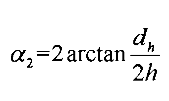
- the relative eccentric position between the light outlet of the ultra-high-speed laser deposition processing head and the rotary body member is the distance between the mid-perpendicular line of the ultra-high-speed laser deposition processing head and the mid-perpendicular line of the rotary body component to be processed l (shown in Figure 1(a)).
- the diameter of the light exit of the ultra-high-speed laser deposition processing head is d h
- the height between the center of the light exit of the ultra-high-speed laser deposition processing head and the rotating body member to be processed is h
- the diameter of the rotating body member to be processed is D
- the incident direction of the laser beam is related to
- ⁇ defined as: (Attachment 1(b)); (Supplementary Figure 1(d)). Therefore, the adjustment range of l complies with ⁇ 1 ⁇ ⁇ ⁇ 2 (Fig. 1(c)), then the adjustment interval of the relative eccentric position between the light outlet of the ultra-high-speed laser deposition processing head and the rotary member is set as
- the process parameters for ultra-high-speed laser deposition processing include laser power of 2000W-10000W, laser spot diameter of 1.5-3mm, laser scanning line speed of 333-2000mm/s, deposition layer overlapping rate is 70-85%, and the protective gas flow rate is 5-20L/min;
- the special powder feeding system for ultra-high-speed laser deposition processing mainly includes a double-barreled synchronous powder feeder, a stirring system, a heating system, a large gas flow regulating device and Anti-static pipeline, in which the single-tube powder feeder has a capacity of up to 5L, a powder feeding rate of 2-150g/min, and a powder feeding accuracy of ⁇ 2g/min, which can realize long-distance transportation of 300-600 mesh powder; ultra-high speed During the laser deposition process, the dilution rate of the molten pool on the surface of the rotary component is generally ⁇ 8%. Therefore, the coincident plane of the focal plane of the laser spot and the focal plane of the powder sink is located within a double-barre
- the relative position between the light outlet of the ultra-high-speed laser deposition processing head and the surface of the processed deposition layer is based on the thickness d of the deposition layer and the change ⁇ d of the thickness of the deposition layer after the secondary melting treatment of the ultra-high-speed laser surface Adjustment (shown in Fig. 2 ), that is, the vertical upward lifting distance of the ultra-high-speed laser deposition processing head on the basis of step 4 is d- ⁇ d.
- the process parameters involved in the secondary melting treatment of the ultra-high-speed laser surface mainly include laser power and scanning speed, which are regulated based on the energy absorption value of the deposited layer, that is Among them, Q is the effective laser energy absorbed by the deposition layer, P is the laser power, ⁇ is the absorption rate of the deposition layer material to the laser beam, d is the laser spot diameter, and L is the melting point formed by the secondary melting of the ultra-high-speed laser surface on the deposition layer surface Pool effective length; ⁇ can be expressed as: where R dz is the resistivity of the deposited layer, ⁇ is the laser wavelength; L can be expressed as Among them, d o is the actual diameter of the laser beam on the surface of the deposited layer, v is the laser scanning speed, and t is the solidification time of the molten pool.
- the invention provides an eccentric ultra-high-speed laser composite manufacturing method for a rotary member.
- the positioning method of the ultra-high-speed laser deposition processing head with a certain eccentric distance it can not only effectively reduce the damage of reflected light to the processing head and prolong its service life, but also It can also change the conventional melt pool shape of ultra-high-speed laser deposition, that is, the "falling" form caused by high-speed motion and gravity is transformed into a "climbing" form, and the full contact between the melt pool and the surface of the rotating body is improved during the ultra-high-speed laser deposition process. Time to form a good bonding performance.
- ultra-high-speed laser deposition combined with ultra-high-speed laser surface secondary melting treatment can not only effectively improve the surface quality and overall compactness of the deposited layer, but also promote the homogenization of the deposited layer structure, and significantly improve the repair or strengthening of the deposited layer. Comprehensive performance.
- Fig. 1 is a schematic diagram of the adjustment range of the relative eccentric position l of the light outlet of the ultra-high-speed laser processing head and the rotary member of the present invention.
- (a) is the interference position of laser beam reflection
- (b) is the minimum eccentricity position
- (c) is the effective eccentricity position
- (d) is the maximum eccentricity position.
- Fig. 2 is a schematic diagram of the thickness variation of the deposition layer prepared by an eccentric ultra-high-speed laser composite manufacturing method for a revolving member according to the present invention, wherein 1 is the revolving member, 2 is the ultra-high-speed laser deposition layer obtained in step 4, and 3 is step 6 The secondary melting layer on the surface of the ultrahigh-speed laser is obtained.
- Fig. 3 is a schematic cross-sectional view of a single-layer and multi-layer stainless steel deposition layer prepared by an eccentric ultra-high-speed laser composite manufacturing method for a revolving member according to the present invention.
- Fig. 4 is an eccentric ultra-high-speed laser composite manufacturing diagram of a 27SiMn hydraulic piston rod in a coal mining machine in an embodiment of the present invention.
- (a) is the substrate installation and equipment debugging
- (b) is the processing process.
- Table 1 shows the tensile performance test results of ultra-high-speed laser deposition layers prepared under different eccentric conditions.
- an enhanced deposition layer is prepared on the surface as an example (shown in Figure 4).
- the diameter of the substrate is 102mm and the length is 2m.
- the powder for ultra-high-speed laser deposition is a special 17Cr4Ni2MoSi iron-based stainless steel powder with a particle size of 25-53 ⁇ m and a chemical composition of: 0.12%C, 17.25%Cr, 1.73%Mo, 4.39% Ni, 0.41% Mn, 1.00% Si, the balance being Fe.
- the specific manufacturing steps are:
- Step 1 The surface of the hydraulic piston rod to be strengthened is polished with 600# sandpaper to remove impurities such as surface scale, then cleaned with alcohol, dried and clamped on an ultra-high-speed laser deposition processing machine tool, and clamped with a three-jaw chuck Tightly fixed (shown in Figure 3(a)), using a radial dynamic balancer to level the hydraulic piston rod, the radial runout error is less than 5 ⁇ m when rotating at 200 rpm;
- Step 2 Use the manipulator to adjust and determine the relative position l of the light outlet of the ultra-high-speed laser deposition processing head and the hydraulic piston rod.
- the diameter d h of the light exit of the ultra-high-speed laser deposition processing head is 8 mm
- the height h between the center of the light exit of the ultra-high-speed laser deposition processing head and the hydraulic column rod is 18 mm
- ⁇ 1 12.53°
- ⁇ 2 25.06°
- the adjustment range of l follows 12.53° ⁇ 25.06°
- the adjustment interval of the relative eccentric position between the light outlet of the ultra-high-speed laser deposition processing head and the hydraulic piston rod is l ⁇ (11.06,21.60mm]
- Step 3 Turn on the ultra-high-speed laser deposition system, set the laser spot diameter to 2mm, the laser power to 3800W, the scanning speed to 1333mm/s, the overlapping rate of the deposition layer to 75%, and the protective gas flow rate to 6.5L/min; the 17Cr4Ni2MoSi iron
- the base powder is dried at 100°C for 2 hours, and then loaded into the double cylinders of the powder feeding system.
- the dilution rate of the surface is less than 5%, and the focal plane of the laser spot is adjusted to coincide with the focal plane of the powder sink, and the coincident focal plane is located 6mm directly above the eccentric position of the hydraulic piston rod;
- Step 4 Edit the processing program on the CNC operation panel of the ultra-high-speed laser deposition processing system according to the size of the hydraulic piston rod and the processing parameters in step 3, start the laser and the ultra-high-speed laser deposition processing machine tool, and prepare a layer of thickness on the surface of the hydraulic piston For a deposition layer of about 126 ⁇ m (shown in Figure 3(a)), after the first deposition layer is processed, the ultra-high-speed laser deposition processing head automatically returns to the initial position of step 4;
- Step 5 Based on the processed surface of the deposited layer, adjust the relative position of the light outlet of the ultra-high-speed laser deposition processing head and the processed surface of the deposited layer in the vertical direction, according to the process parameter conditions at the same laser power and scanning speed.
- the composite processing test results repeated several times below show that after the secondary melting treatment on the surface of the ultra-high-speed laser, the thickness of the ultra-high-speed laser deposition layer decreases by 9-12 ⁇ m, so on the basis of step 4, the ultra-high-speed laser processing head is lifted vertically by 114 -117 ⁇ m;
- Step 6 Based on the existing research basis, the absorption rate of iron-based stainless steel to the laser beam is about 0.35, then Q can be expressed as It is further measured that the actual diameter of the laser beam on the surface of the deposited layer is 3.6mm, but the scanning speed of ultra-high-speed laser deposition can reach more than 1000mm/s, so L can be approximately expressed as vt, and Q can be further expressed as: 128.56P ⁇ e - vt , that is, the effective laser energy absorbed by the deposited layer is proportional to the laser power and inversely proportional to the scanning speed.
- Step 7 Repeat steps 4, 5 and 6 according to the overall thickness requirements of the reinforced layer on the surface of the rotating body component used in engineering practice, and prepare a deposition layer with excellent performance on the surface of the rotating body component.
- the application of the technical solution provided by the present invention can not only effectively reduce the damage of reflected light to the processing head and prolong its service life, but also can significantly eliminate the problems of adhesion of molten powder particles on the surface of the ultra-high-speed laser deposition layer and defects such as internal cracks and pores.
Landscapes
- Engineering & Computer Science (AREA)
- Chemical & Material Sciences (AREA)
- Materials Engineering (AREA)
- Manufacturing & Machinery (AREA)
- Automation & Control Theory (AREA)
- Mechanical Engineering (AREA)
- Composite Materials (AREA)
- Chemical Kinetics & Catalysis (AREA)
- Metallurgy (AREA)
- Organic Chemistry (AREA)
- Laser Beam Processing (AREA)
Abstract
Description
优选的,所述步骤二中,超高速激光沉积加工头出光口与回转体构件的相对偏心位置,即为超高速激光沉积加工头的中垂线与待加工回转体构件的中垂线的 距离l(附图1(a)所示)。其中超高速激光沉积加工头出光口的直径为d h、超高速激光沉积加工头出光口中心与待加工回转体构件高度为h、待加工回转体构件的直径为D以及激光束的入射方向与反射方向的夹角为α,定义:



Claims (7)
- 一种回转体构件偏心超高速激光复合制造方法,其特征在于,包括以下步骤:步骤一:对待加工回转体构件进行预处理,然后装夹到超高速激光沉积加工机床上面;步骤二:根据待加工回转体构件的直径与超高速激光沉积加工头的出光口直径,利用机械手调整和控制超高速激光沉积加工头出光口与回转体构件的相对偏心位置;步骤三:开启超高速激光沉积加工系统和超高速激光沉积加工专用送粉系统,根据回转体构件的修复或者表面强化的要求,选择合适的超高速激光沉积加工用的工艺参数和专用粉末,调整激光光斑焦平面与粉末汇聚焦平面重合,根据熔池在回转体构件表面的稀释率,采取正离焦的方式位于待加工回转体构件的正上方一定距离内;步骤四:在超高速激光沉积加工系统的数控操作面板上面编辑加工程序,进行超高速激光沉积加工,在回转体构件的表面制备一层符合厚度要求的沉积层,在第一道沉积层加工完毕后,超高速激光沉积加工头自动返回步骤四的初始位置;步骤五:以加工好的沉积层表面为基准,在竖直方向上调整超高速激光沉积加工头出光口与加工好的沉积层表面的相对位置;步骤六:再次开启超高速激光沉积加工系统,不打开超高速激光沉积加工专用送粉系统,选择合适的工艺参数对加工好的沉积层进行超高速激光表面二次熔融处理;步骤七:根据工程实际应用的回转体构件表面修复或者强化层的整体厚度需求,重复步骤四、五和六,在回转体构件表面进行优异性能的沉积层制备。
- 根据权利1要求所述的一种回转体构件偏心超高速激光复合制造方法,其特征在于:步骤一中,所述超高速激光沉积加工机床为五轴联动的数控机床,X轴的最大工作行程为5000mm,移动速度为0-10000mm/min;Y轴的最大工作行程为350mm,移动速度为0-10000mm/min,Z轴的最大工作行程为600mm,主轴伺服转速0-300r/min,三爪卡盘直径为Ф640mm。。
- 根据权利1要求所述的一种回转体构件偏心超高速激光复合制造方法,其特征在于:步骤一中,对待加工回转体构件的预处理包括两种形式:对于具有一 定损伤深度的表面修复要求的回转体构件,先进行粗车加工外圆面直至去除整个损伤部位;对于表面强化的回转体构件,直接将表面打磨光滑,并用酒精清洗干净后吹干。
- 根据权利1要求所述的一种回转体构件偏心超高速激光复合制造方法,其特征在于:步骤二中,超高速激光沉积加工头出光口与回转体构件的相对偏心位置,即为超高速激光沉积加工头的中垂线与待加工回转体构件的中垂线的距离l;其中超高速激光沉积加工头出光口的直径为d h、超高速激光沉积加工头出光口中心与待加工回转体构件高度为h、待加工回转体构件的直径为D以及激光束的入射方向与反射方向的夹角为α,定义:l调节范围遵循α 1<α≤α 2,则设置超高速激光沉积加工头出光口与回转体构件的相对偏心位置的调节区间为


- 根据权利1要求所述的一种回转体构件偏心超高速激光复合制造方法,其特征在于:步骤三中,超高速激光沉积加工用的工艺参数包括激光功率为2000W-10000W,激光光斑直径为1.5-3mm,激光扫描线速度为333-2000mm/s,沉积层搭接率为70-85%,保护气流量为5-20L/min;所述的超高速激光沉积加工专用送粉系统主要包括双筒同步送粉器、搅拌系统、加温系统、大气体流量调节装置和防静电管路,其中单筒送粉器的容量可达5L,送粉速率为2-150g/min,送粉精度为±2g/min,可以实现300-600目粉末的长距离输送;激光光斑焦平面与粉末汇聚焦平面的重合面位于待加工回转体构件偏心位置正上方3-10mm的距离内。
- 根据权利1要求所述的一种回转体构件偏心超高速激光复合制造方法,其特征在于:步骤五中,所述超高速激光沉积加工头出光口与加工好的沉积层表面的相对位置,基于沉积层的厚度d与超高速激光表面二次熔融处理后沉积层厚度变化Δd进行调整,即超高速激光沉积加工头在步骤四的基础上竖直向上抬升的距离为d-Δd。
- 根据权利1要求所述的一种回转体构件偏心超高速激光复合制造方法,其特征在于:步骤六中,超高速激光表面二次熔融处理涉及到的工艺参数主要包括 激光功率和扫描速度,基于沉积层的能量吸收值进行调控,即其中Q为沉积层吸收的有效激光能量,P为激光功率,η为沉积层材料对激光束的吸收率,d为激光光斑直径,L为超高速激光表面二次熔融在沉积层表面形成的熔池有效长度;η可以表示为:
 其中R dz为沉积层的电阻率,λ为激光波长;L可以表示为
 其中,d o为激光光束在沉积层表面的实际直径,v为激光扫描速度,t为熔池凝固时间。
Priority Applications (1)
| Application Number | Priority Date | Filing Date | Title |
|---|---|---|---|
| US18/273,270 US12097559B2 (en) | 2022-02-22 | 2022-02-25 | Eccentric extreme high-speed-rate laser hybrid manufacturing method for rotary engineering component |
Applications Claiming Priority (2)
| Application Number | Priority Date | Filing Date | Title |
|---|---|---|---|
| CN202210161475.3A CN115138860B (zh) | 2022-02-22 | 2022-02-22 | 一种回转体构件偏心超高速激光复合制造方法 |
| CN202210161475.3 | 2022-02-22 |
Publications (1)
| Publication Number | Publication Date |
|---|---|
| WO2023159477A1 true WO2023159477A1 (zh) | 2023-08-31 |
Family
ID=83405653
Family Applications (1)
| Application Number | Title | Priority Date | Filing Date |
|---|---|---|---|
| PCT/CN2022/077959 Ceased WO2023159477A1 (zh) | 2022-02-22 | 2022-02-25 | 一种回转体构件偏心超高速激光复合制造方法 |
Country Status (3)
| Country | Link |
|---|---|
| US (1) | US12097559B2 (zh) |
| CN (1) | CN115138860B (zh) |
| WO (1) | WO2023159477A1 (zh) |
Families Citing this family (1)
| Publication number | Priority date | Publication date | Assignee | Title |
|---|---|---|---|---|
| CN116475429B (zh) * | 2023-04-25 | 2026-04-21 | 张冲 | 一种多材料功能梯度环形构件熔融沉积增材制造方法 |
Citations (8)
| Publication number | Priority date | Publication date | Assignee | Title |
|---|---|---|---|---|
| US5179260A (en) * | 1990-08-17 | 1993-01-12 | Siemens Aktiengesellschaft | Device and process for the laser welding of a tube |
| CN101468393A (zh) * | 2007-12-26 | 2009-07-01 | 沈阳航空工业学院 | 一种金属粉末激光成形系统的金属粉末送给装置 |
| CN102179517A (zh) * | 2011-04-15 | 2011-09-14 | 华中科技大学 | 一种激光感应复合熔化直接成形方法及装置 |
| CN108103498A (zh) * | 2017-12-22 | 2018-06-01 | 北京机科国创轻量化科学研究院有限公司 | 一种超高速激光熔覆工艺 |
| CN108220952A (zh) * | 2017-12-22 | 2018-06-29 | 北京机科国创轻量化科学研究院有限公司 | 一种采用超高速率激光熔覆方法制造的液压支架立柱 |
| CN111218684A (zh) * | 2020-02-11 | 2020-06-02 | 江苏大学 | 一种激光辅助超高速激光熔覆制备高熔点涂层的方法 |
| CN111501038A (zh) * | 2020-02-11 | 2020-08-07 | 江苏大学 | 一种激光复合超高速激光熔覆制备高性能铁基涂层的方法 |
| CN113957436A (zh) * | 2021-10-26 | 2022-01-21 | 镭速(北京)智能科技有限公司 | 高速激光熔覆枪 |
Family Cites Families (4)
| Publication number | Priority date | Publication date | Assignee | Title |
|---|---|---|---|---|
| US10792757B2 (en) * | 2016-10-25 | 2020-10-06 | Arcam Ab | Method and apparatus for additive manufacturing |
| CN108505035B (zh) * | 2018-04-11 | 2020-09-25 | 江苏大学 | 一种用于汽轮机末级叶片损伤件的振动熔覆修复工艺 |
| EP3594446B1 (en) * | 2018-07-13 | 2021-10-20 | ANSALDO ENERGIA S.p.A. | Method of restoring a blade or vane platform |
| CN111545749B (zh) * | 2020-04-24 | 2022-06-21 | 江苏大学 | 一种超高速激光熔覆复杂曲面回转体的方法 |
-
2022
- 2022-02-22 CN CN202210161475.3A patent/CN115138860B/zh active Active
- 2022-02-25 US US18/273,270 patent/US12097559B2/en active Active
- 2022-02-25 WO PCT/CN2022/077959 patent/WO2023159477A1/zh not_active Ceased
Patent Citations (8)
| Publication number | Priority date | Publication date | Assignee | Title |
|---|---|---|---|---|
| US5179260A (en) * | 1990-08-17 | 1993-01-12 | Siemens Aktiengesellschaft | Device and process for the laser welding of a tube |
| CN101468393A (zh) * | 2007-12-26 | 2009-07-01 | 沈阳航空工业学院 | 一种金属粉末激光成形系统的金属粉末送给装置 |
| CN102179517A (zh) * | 2011-04-15 | 2011-09-14 | 华中科技大学 | 一种激光感应复合熔化直接成形方法及装置 |
| CN108103498A (zh) * | 2017-12-22 | 2018-06-01 | 北京机科国创轻量化科学研究院有限公司 | 一种超高速激光熔覆工艺 |
| CN108220952A (zh) * | 2017-12-22 | 2018-06-29 | 北京机科国创轻量化科学研究院有限公司 | 一种采用超高速率激光熔覆方法制造的液压支架立柱 |
| CN111218684A (zh) * | 2020-02-11 | 2020-06-02 | 江苏大学 | 一种激光辅助超高速激光熔覆制备高熔点涂层的方法 |
| CN111501038A (zh) * | 2020-02-11 | 2020-08-07 | 江苏大学 | 一种激光复合超高速激光熔覆制备高性能铁基涂层的方法 |
| CN113957436A (zh) * | 2021-10-26 | 2022-01-21 | 镭速(北京)智能科技有限公司 | 高速激光熔覆枪 |
Also Published As
| Publication number | Publication date |
|---|---|
| US20240139813A1 (en) | 2024-05-02 |
| US12097559B2 (en) | 2024-09-24 |
| CN115138860B (zh) | 2023-06-13 |
| CN115138860A (zh) | 2022-10-04 |
Similar Documents
| Publication | Publication Date | Title |
|---|---|---|
| CN110144583B (zh) | 一种宽光束、可调送粉角的快速高效半导体激光熔覆装置 | |
| CN102465294B (zh) | 一种大面积激光熔覆高硬度镍基合金材料的方法 | |
| CN101775525B (zh) | 一种连铸结晶器铜板激光熔覆钴基合金涂层材料及工艺 | |
| CN103255412B (zh) | 一种用于轧辊工作面的激光熔覆高硬度材料的工艺方法 | |
| CN109706449B (zh) | 一种修复盾构机主轴承的涂层材料及工艺方法 | |
| CN108165978A (zh) | 一种采用超高速激光熔覆技术修复核电海水泵轴的方法 | |
| CN108165981A (zh) | 一种超高速率激光熔覆制备奥氏体不锈钢耐蚀涂层的方法 | |
| CN105543838A (zh) | 一种船用曲轴的再制造方法 | |
| CN104005019A (zh) | 一种铝合金表面复合涂层的制备方法 | |
| CN111501038A (zh) | 一种激光复合超高速激光熔覆制备高性能铁基涂层的方法 | |
| CN103014249B (zh) | 一种大幅度提高RuT300表面硬度的激光熔凝淬火工艺 | |
| CN105586562A (zh) | 一种混凝土泵车活塞杆再制造的工艺 | |
| CN107805809A (zh) | 一种汽车模具表面涂膜修复工艺 | |
| CN106381488B (zh) | 连铸结晶器足辊涂层的制备方法 | |
| CN115341212A (zh) | 双光束超高速激光熔覆与激光冲击锻打的复合加工方法 | |
| CN103924238B (zh) | 在Q550钢上激光熔覆Ni基合金+B4C增强相的方法 | |
| CN109487265A (zh) | 一种大型旋转机械轴瓦激光快速修复工艺方法 | |
| WO2023159477A1 (zh) | 一种回转体构件偏心超高速激光复合制造方法 | |
| CN113337815A (zh) | 一种基于高速激光熔覆法制备双尺度铁基复合梯度涂层的方法 | |
| CN115710703B (zh) | 超高速激光熔覆制备耐腐蚀耐磨熔覆层的方法及机床 | |
| CN115261870A (zh) | 基于豪克能技术的短流程复合超高速激光熔覆加工方法 | |
| CN110747462A (zh) | 一种高速激光熔覆工艺 | |
| CN111850547B (zh) | 一种多轴超高速激光熔覆喷头 | |
| CN107931827B (zh) | 一种高合金激光快速修复方法 | |
| CN118835241A (zh) | 一种球墨铸铁复合激光熔覆材料及其制备方法 |
Legal Events
| Date | Code | Title | Description |
|---|---|---|---|
| WWE | Wipo information: entry into national phase |
Ref document number: 18273270 Country of ref document: US |
|
| 121 | Ep: the epo has been informed by wipo that ep was designated in this application |
Ref document number: 22927763 Country of ref document: EP Kind code of ref document: A1 |
|
| NENP | Non-entry into the national phase |
Ref country code: DE |
|
| 122 | Ep: pct application non-entry in european phase |
Ref document number: 22927763 Country of ref document: EP Kind code of ref document: A1 |
|
| 122 | Ep: pct application non-entry in european phase |
Ref document number: 22927763 Country of ref document: EP Kind code of ref document: A1 |
|
| 32PN | Ep: public notification in the ep bulletin as address of the adressee cannot be established |
Free format text: NOTING OF LOSS OF RIGHTS PURSUANT TO RULE 112(1) EPC (EPO FORM 1205A DATED 20/03/2025) |