WO2023157262A1 - 浮体構造物、変位量取得方法、および支持状態判定方法 - Google Patents
浮体構造物、変位量取得方法、および支持状態判定方法 Download PDFInfo
- Publication number
- WO2023157262A1 WO2023157262A1 PCT/JP2022/006775 JP2022006775W WO2023157262A1 WO 2023157262 A1 WO2023157262 A1 WO 2023157262A1 JP 2022006775 W JP2022006775 W JP 2022006775W WO 2023157262 A1 WO2023157262 A1 WO 2023157262A1
- Authority
- WO
- WIPO (PCT)
- Prior art keywords
- tank
- dome
- outer tank
- inner tank
- main body
- Prior art date
- Legal status (The legal status is an assumption and is not a legal conclusion. Google has not performed a legal analysis and makes no representation as to the accuracy of the status listed.)
- Ceased
Links
Images

Classifications
-
- B—PERFORMING OPERATIONS; TRANSPORTING
- B63—SHIPS OR OTHER WATERBORNE VESSELS; RELATED EQUIPMENT
- B63B—SHIPS OR OTHER WATERBORNE VESSELS; EQUIPMENT FOR SHIPPING
- B63B25/00—Load-accommodating arrangements, e.g. stowing, trimming; Vessels characterised thereby
- B63B25/02—Load-accommodating arrangements, e.g. stowing, trimming; Vessels characterised thereby for bulk goods
- B63B25/08—Load-accommodating arrangements, e.g. stowing, trimming; Vessels characterised thereby for bulk goods fluid
- B63B25/12—Load-accommodating arrangements, e.g. stowing, trimming; Vessels characterised thereby for bulk goods fluid closed
- B63B25/16—Load-accommodating arrangements, e.g. stowing, trimming; Vessels characterised thereby for bulk goods fluid closed heat-insulated
Definitions
- the present disclosure relates to floating structures.
- Patent Literature 1 discloses a liquefied gas carrier in which a double-hulled tank mounted on the hull is covered with a tank cover.
- a vacuum layer is formed as a heat insulating layer between the inner and outer tanks of the double-hulled tank.
- the inner tank includes an inner tank main body portion for storing liquefied gas and an inner tank dome projecting upward from the inner tank main body portion
- the outer tank includes an outer tank main body portion surrounding the inner tank main body portion, It includes an outer hull dome surrounding the inner hull dome.
- the inner tank dome is a portion for consolidating various types of piping such as liquefied gas transfer piping and electrical piping, and is penetrated by these piping.
- a bellows is incorporated in the outer tank dome.
- the bellows divides the outer tank dome into an upper movable portion and a lower fixed portion.
- the movable portion of the outer tank dome is connected to the inner tank dome by a connecting member so as to be displaced together with the inner tank dome when the inner tank thermally shrinks.
- a support member is provided between the outer tank main body and the inner tank main body to support the inner tank main body from below.
- an object of the present disclosure is to provide a floating structure capable of confirming whether or not there is a problem with a support member between an outer tank main body and an inner tank main body of a double-hulled tank.
- a floating structure includes a hull and a double-hull tank mounted on the hull, wherein the double-hull tank includes an inner tank main body for storing liquefied gas, and the inner tank main body heat insulation between an inner tank including an inner tank dome protruding upward from the inner tank, an outer tank main body surrounding the inner tank main body, and an outer tank dome surrounding at least a lower portion of the inner tank dome; an outer tank forming a layer; a support member provided between the outer tank main body and the inner tank main body for supporting the inner tank main body; a connection member that connects a movable portion of an outer tank dome and a fixed portion of the outer tank dome fixed to the outer tank main body or the outer tank main body so as to be relatively displaceable; and the inner tank dome and the outer tank dome. and a connecting member that connects the movable portion of the outer tank dome and the hull via a deformable member.
- a floating structure capable of confirming whether or not there is a problem with the support member between the outer tank main body and the inner tank main body of the double-hulled tank.
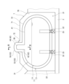
- FIG. 1 is a side view of a floating structure according to an embodiment of the present disclosure
- FIG. FIG. 2 is a cross-sectional view of part of the floating structure shown in FIG. 1
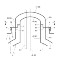
- 3 is a cross-sectional view taken along line III-III of FIG. 2
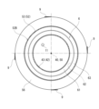
- FIG. FIG. 4 is a cross-sectional view taken along line IV-IV of FIG. 3
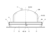
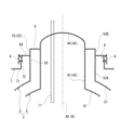
- FIG. 4 is an external view of a cylindrical portion of a tank dome and an outer tank dome; It is sectional drawing of the inner tank dome and the outer tank dome in a modification.
- FIG. 1 shows a floating structure 1 according to one embodiment of the present disclosure.
- the floating structure 1 of this embodiment is a liquefied gas carrier.
- the floating structure 1 may be, for example, a vessel such as a liquefied gas fueled vessel, a liquefied gas bunkering vessel, or a floating production, storage and offloading unit (FPSO), a floating LNG storage and regasification unit (FSRU), a floating production volume. It may be an offloading facility (FPO), a floating storage offloading facility (FSO), or the like.
- This floating structure 1 includes a hull 2 and two double-hulled tanks 3 mounted on the hull 2 .
- the double-hull tanks 3 are arranged in the longitudinal direction, but if the ship is wide, they may be arranged in the transverse direction. Further, the number of double-hulled tanks 3 mounted on the hull 2 may be one, or may be three or more.
- each double-hull tank 3 includes an inner tank 4 and an outer tank 5 enclosing the inner tank 4 .
- a heat insulating layer 31 is formed between the inner bath 4 and the outer bath 5 .
- the heat insulating layer 31 is a vacuum layer.
- the outer surface of the inner tank 4 is covered with a vacuum heat insulating material, and no object exists between the vacuum heat insulating material and the inner surface of the outer tank 5. Gaps may be formed.
- the vacuum heat insulating material is, for example, a multi-layer sheet in which radiation shielding films and spacers are alternately laminated.
- the vacuum space may be filled with perlite, which is a granular heat insulating material.
- each double-shell tank 3 has a horizontally long cylindrical shape.
- the shape of the double-shell tank 3 may be spherical, cubic, or rectangular parallelepiped.
- the inner tank 4 includes an inner tank main body 41 that stores liquefied gas, and an inner tank dome 42 that protrudes upward from the inner tank main body 41 .
- the outer tub 5 includes an outer tub body portion 51 surrounding the inner tub body portion 41 and an outer tub dome 52 surrounding at least a lower portion of the inner tub dome 42 .
- the outer tank dome 52 surrounds the entire inner tank dome 42 .
- Liquefied gas includes, for example, liquefied petroleum gas (LPG, about -45°C), liquefied ethylene gas (LEG, about -100°C), liquefied natural gas (LNG, about -160°C), liquefied oxygen (LO 2 , about - 180° C.), liquefied hydrogen (LH 2 , about ⁇ 250° C.), and liquefied helium (LHe, about ⁇ 270° C.).
- LPG liquefied petroleum gas
- LPG liquefied ethylene gas
- LNG liquefied natural gas
- LO 2 liquefied oxygen
- LH 2 liquefied hydrogen
- LHe liquefied helium
- the inner tank main body 41 includes a body extending horizontally with a constant cross-sectional shape, and hemispherical closing parts that close the openings on both sides of the body.
- the closing portion may be flat perpendicular to the trunk portion, or may be dish-shaped.
- the inner tank dome 42 protrudes upward from the body of the inner tank main body 41 .
- the protruding direction of the inner tank dome 42 is parallel to the vertical direction in this embodiment, but may be slightly inclined with respect to the vertical direction.
- the outer tank main body part 51 has a shape obtained by enlarging the inner tank main body part 41 . That is, the outer tank main body 51 includes a body having a constant cross-sectional shape and extending in the horizontal direction and having a larger diameter than the body of the inner tank main body 41, and hemispherical closing portions closing the openings on both sides of the body. including.
- the outer tank dome 52 also has a shape obtained by enlarging the inner tank dome 42 .
- the outer tank main body portion 51 does not have to have the enlarged shape of the inner tank main body portion 41
- the outer tank dome 52 does not have to have the enlarged shape of the inner tank dome 42 .
- the inner tank dome 42 is a part for consolidating various pipes 11 (see FIG. 3, only one pipe is drawn as a representative in FIG. 3) such as cryogenic fluid transfer pipes and electrical pipes. be done.
- the outer tank dome 52 surrounds the entire inner tank dome 42 , so the pipe 11 also penetrates the outer tank dome 52 .
- the hull 2 has two cargo holds 21 that open upward.
- the cargo holds 21 are arranged in the longitudinal direction, and the cargo holds 21 are separated from each other by bulkheads 22 .
- a double-hull tank 3 is arranged inside each cargo hold 21 .
- a pair of saddles 23 are provided that are separated from each other in the longitudinal direction.
- the saddle 23 supports the outer tank body 51 of the outer tank 5 of the double-shell tank 3 .
- a pair of support members 32 are provided between the inner tank 4 and the outer tank 5 of the double-shell tank 3 to support the inner tank main body 41 from below.
- the support member 32 is provided at the same position as the saddle 23 in this embodiment, the support member 32 may be provided at a different position from the saddle 23 .
- the number and shape of the support members 32 can be changed as appropriate according to the shape of the double-shell tank 3.
- a cross-shaped support member that is, a shape in which two arcs intersect
- Only one may be provided.
- the support member 32 of the present embodiment supports the inner tank main body 41 from below, the support member 32 may support the inner tank main body 41 from a direction other than the downward direction.
- a tank cover 7 is arranged above each double-shell tank 3 .
- the tank cover 7 forms part of the hull 2 .
- Each tank cover 7 covers the corresponding double-hull tank 3 from above and forms a holding space 70 surrounding the double-hull tank 3 together with the corresponding cargo hold 21 .
- the outer tank main body 51 of the outer tank 5 described above is positioned below the tank cover 7 , and the outer tank dome 52 penetrates the tank cover 7 .
- the holding space 70 is filled with an inert gas. Nitrogen, argon, or the like can be used as the inert gas with which the holding space 70 is filled.
- the inert gas serves to reduce the pressure in the holding space 70 and prevent condensation on the surface of the double-shell tank 3 .
- the inert gas filled in the holding space 70 serves to prevent liquefied oxygen from being generated around the double-shell tank 3. also fulfill
- the holding space 70 may be filled with a gas other than the inert gas (for example, dry air).
- the holding space 70 may not be filled with anything and the gas in the holding space 70 may be normal air.
- the elastic member 8, which will be described later, can be omitted.
- the inner tank dome 42 includes a tubular peripheral wall 43 rising from the inner tank main body 41 and a ceiling wall 44 closing an upper opening of the peripheral wall 43 .
- the outer tank dome 52 includes a tubular peripheral wall 53 rising from the outer tank main body 51 and a ceiling wall 54 closing the upper opening of the peripheral wall 53 .
- the pipe 11 described above penetrates the ceiling wall 44 of the inner tank dome 42 and the ceiling wall 54 of the outer tank dome 52, but the pipe 11 is bent 90 degrees inside the inner tank dome 42 to It may penetrate through the peripheral wall 43 of the dome 42 and the peripheral wall 53 of the outer tank dome 52 .
- connection member is incorporated in the peripheral wall 53 of the outer tank dome 52 .
- the connecting member is a vertically corrugated bellows 55 .
- the bellows 55 divides the outer tub dome 52 into a lower fixed portion 52A and an upper movable portion 52B.
- the fixed portion 52A is fixed to the outer tank main body portion 51 .
- the movable portion 52 ⁇ /b>B is a portion penetrated by the pipe 11 and is displaced with respect to the outer tank body portion 51 .
- the outer tub dome 52 may not be divided into the fixed portion 52A and the movable portion 52B.
- the entire outer bath dome 52 may be the movable portion 52B.
- the bellows 55 is positioned between the outer tank dome 52 and the outer tank main body 51, which is the movable part 52B.
- a connection member other than the bellows 55 that connects the movable portion 52B and the fixed portion 52A or the outer tank dome 52 so as to be relatively displaceable may be used.
- the connection member for example, a telescopic structure, a leaf spring, or the like may be used.
- the inner tank dome 42 and the movable portion 52B of the outer tank dome 52 are connected by a ring-shaped connecting member 6 .
- the connecting member 6 includes an inner ring 61 that protrudes radially outward from the peripheral wall 43 of the inner tank dome 42 , and a connecting member 6 positioned below the inner ring 61 and radially extending from the peripheral wall 53 of the outer tank dome 52 . It includes an inwardly projecting outer ring 63 and a tubular partition wall 62 connecting the outer peripheral edge of the inner ring 61 and the inner peripheral edge of the outer ring 63 .
- the connecting member 6 can be changed as appropriate.
- the connecting member 6 may be a cylindrical member interposed between the ceiling wall 44 of the inner tank dome 42 and the ceiling wall 54 of the outer tank dome 52 .
- the tank cover 7 has a ceiling portion 71 facing the bottom of the cargo hold 21 with the double-shell tank 3 interposed therebetween, and a cylindrical portion 72 protruding upward from the ceiling portion 71 and into which the outer tank dome 52 is inserted.
- the movable portion 52B of the outer tank dome 52 has a dome flange 56 protruding radially outward from the peripheral wall 53 .
- the dome flange 56 protrudes above the tubular portion 72 of the tank cover 7 .
- An annular deformation member is interposed between the tubular portion 72 of the tank cover 7 and the dome flange 56 .
- the deformation member is the elastic member 8 .
- the elastic member 8 seals between the tubular portion 72 of the tank cover 7 and the dome flange 56, and is elastically deformable in the vertical direction.
- the elastic member 8 for example, expansion rubber or bellows can be used.
- a deformable member other than the elastic member 8 that can be simply deformed may be used.
- the deformation member for example, a telescopic structure, a deformable cloth, or the like can be used.
- a plurality of displacement measuring mechanisms 9 are arranged on the circumference surrounding the outer tank dome 52 (the circumference centered on the center line 50 of the outer tank dome 52). These displacement measuring mechanisms 9 are for measuring the displacement of the movable portion 52B of the outer tank dome 52 with respect to the tank cover 7. As shown in FIG.
- displacement measuring mechanisms 9 are arranged at intervals of 90 degrees.
- the number of displacement measuring mechanisms 9 may be two, three, or five or more. Also, the number of displacement measuring mechanisms 9 may be one.
- the displacement measuring mechanism 9 is arranged around the tubular portion 72 of the tank cover 7 .
- the displacement measuring mechanism 9 is provided on the dome flange 56 so as to be displaced together with the movable portion 52B of the outer tank dome 52 .
- the displacement measuring mechanism 9 may be provided on the tubular portion 72 of the tank cover 7 so as not to be displaced even if the movable portion 52B of the outer tank dome 52 is displaced.
- each displacement measuring mechanism 9 is a ruler on which scales are formed not only along the vertical direction but also along the horizontal direction.
- the scale may be formed only along the vertical direction on the ruler.
- various mechanisms other than the ruler can be employed.
- the displacement measuring mechanism 9 may be a contact-type displacement gauge, a non-contact displacement gauge, rubber with a grid-like mesh drawn on it, or the like.
- the displacement measuring mechanism 9 may be formed integrally with the deformation member (the elastic member 8 in this embodiment). That is, the deformable member may function as the displacement measuring mechanism 9 .
- a scale may be written on the deformable member itself.
- two of the four displacement measuring mechanisms 9 are arranged so as to be in contact with a plane parallel to the longitudinal direction passing through the centerline 50 of the outer tank dome 52, and the remaining two It is arranged so as to be in contact with a plane parallel to the ship width direction passing through the centerline 50 of the tank dome 52 .
- a reference mark is formed by engraving or the like. The position of this fiducial mark is measured using the ruler described above.
- the elastic member 8 interposed between the tubular portion 72 of the tank cover 7 and the dome flange 56 is crushed, The movable portions 52B of the inner bath dome 42 and the outer bath dome 52 are displaced downward. Then, the displacement of the movable portion 52B of the outer tank dome 52 is measured by the displacement measuring mechanism 9 as relative displacement with respect to the tank cover 7 . Moreover, the displacement measuring mechanism 9 is arranged on the circumference surrounding the outer tank dome 52 . Therefore, when the inner tank 4 is thermally contracted, it can be confirmed whether the relative displacement of the movable portion 52B of the outer tank dome 52 with respect to the tank cover 7 is as designed. It is possible to check whether or not there is any problem with the support member 32 between the body portion 41 and the main body portion 41 . That is, the support state of the inner tank 4 by the support member 32 can be determined.
- the four displacement measuring mechanisms 9 are arranged at intervals of 90 degrees, the inclination of the movable portion 52B of the outer tank dome 52 with respect to the tank cover 7 can also be confirmed.
- a ruler having scales formed along the vertical and horizontal directions is used as the displacement measuring mechanism 9, so that the amount of displacement in the vertical and horizontal directions at the measurement point can be grasped instantaneously. be able to.
- the outer tank dome 52 may surround only the lower part of the inner tank dome 42, as shown in FIG.
- the outer tank dome 52 may be composed only of the peripheral wall 53 in which the bellows 55 is incorporated, and the connecting member 6 may be a ring plate that connects the upper end of the peripheral wall 53 and the peripheral wall 43 of the inner tank dome 42.
- the outer tank dome 52 surrounds only the lower part of the inner tank dome 42 as shown in FIG. be provided.
- the heat insulating layer 31 does not necessarily have to be a vacuum layer, and the space between the inner tank 4 and the outer tank 5 may be filled with a gas with low thermal conductivity such as argon. However, if the heat insulating layer 31 is a vacuum layer, the heat insulating performance of the heat insulating layer 31 can be improved.
- the displacement measuring mechanism 9 may be arranged inside the tubular portion 72 of the tank cover 7 and around the peripheral wall 53 of the outer tank dome 52 or the bellows 55 . However, in this case, it is necessary for the operator to enter the holding space 70 in order to visually recognize the displacement measuring mechanism 9 . For that purpose, it is necessary to replace the inert gas in the holding space 70 with air. On the other hand, if the displacement measuring mechanism 9 is arranged around the tubular portion 72 of the tank cover 7 as in the above-described embodiment, the operator can visually recognize the displacement measuring mechanism 9 outside the holding space 70. There is no need to replace the inert gas in the holding space 70 with air.
- the displacement measuring mechanism 9 is used to measure the amount of displacement of the movable portion 52B with respect to the tank cover 7 of the hull 2, whereby the displacement of the inner tank 4 with respect to the outer tank 5 (outer tank main body 51) is The displacement amount was obtained.
- the displacement amount of the movable portion 52B with respect to the tank cover 7 of the hull 2 may be measured using a measuring device separately prepared by the operator without using the displacement measuring mechanism 9 .
- the double-shell tank 3 does not have to be equipped with the displacement measuring mechanism 9 .
- the amount of displacement of the inner tank 4 with respect to the outer tank 5 may be obtained by measuring the amount of displacement of the movable portion 52B with respect to the portion of the hull 2 other than the tank cover 7 .
- the amount of displacement of the inner tank 4 with respect to the outer tank 5 may be obtained by measuring the amount of displacement of the movable portion 52B with respect to the hull 2 (any part of the hull 2).
- the "movable portion 52B" may be "a portion that follows the displacement of the inner tank 4 with respect to the outer tank 5".
- the amount of displacement of the inner tank 4 with respect to the outer tank 5 may be obtained by measuring the amount of relative displacement between the portion that follows the displacement of the inner tank 4 with respect to the outer tank 5 and the hull 2 . If the portion that follows the displacement of the inner tank 4 with respect to the outer tank 5 is located outside the inner tank 4, the amount of relative displacement can be easily measured.
- a floating structure includes a hull and a double-hull tank mounted on the hull, wherein the double-hull tank includes an inner tank main body for storing liquefied gas, and the inner tank main body heat insulation between an inner tank including an inner tank dome protruding upward from the inner tank, an outer tank main body surrounding the inner tank main body, and an outer tank dome surrounding at least a lower portion of the inner tank dome; an outer tank forming a layer; a support member provided between the outer tank main body and the inner tank main body for supporting the inner tank main body; a connection member that connects a movable portion of an outer tank dome and a fixed portion of the outer tank dome fixed to the outer tank main body or the outer tank main body so as to be relatively displaceable; and the inner tank dome and the outer tank dome. and a connecting member that connects the movable portion of the outer tank dome and the hull via a deformable member.
- the deformable member interposed between the hull and the movable portion of the outer tank dome is crushed, and the movable portions of the inner and outer tank domes are lowered. is displaced to Then, displacement of the movable portion of the outer tank dome is measured as relative displacement with respect to the hull. Therefore, it is possible to check whether the relative displacement of the movable portion of the outer tank dome with respect to the hull is as designed when the inner tank is thermally shrunk. It is possible to check whether or not the support member has a problem, that is, to determine the state of support of the inner tank by the support member. Moreover, since the relative displacement of the movable portion of the outer tank dome with respect to the hull can be observed around the deformation member, the relative displacement can be easily measured.
- the hull includes a tank cover that covers the double-shell tank, the movable portion of the outer tank dome has a dome flange projecting above the tank cover, and the deformation member comprises the tank cover and the dome flange. may be interposed between According to this configuration, by measuring the amount of displacement of the dome flange with respect to the tank cover, which is easy to measure, it is possible to obtain the amount of displacement of the inner tank with respect to the outer tank, thereby determining the state of support of the inner tank by the support member. can be done.
- the double-shell tank may further include at least one displacement measuring mechanism arranged on a circumference surrounding the outer shell dome for measuring the amount of displacement of the movable portion of the outer shell dome with respect to the tank cover. good. According to this configuration, the displacement amount of the movable portion of the outer tank dome with respect to the tank cover can be measured using the displacement measuring mechanism without separately preparing a measuring device.
- the displacement amount acquisition method acquires the displacement amount of the inner tank with respect to the outer tank in the above floating structure by measuring the displacement amount of the movable portion of the outer tank dome with respect to the hull. According to this method, the amount of displacement of the inner tank relative to the outer tank can be obtained without accessing between the inner tank and the inner and outer tanks.
- a support state determination method determines the support state of the inner tank by the support members by measuring the amount of displacement of the movable portion of the outer tank dome with respect to the tank cover in the floating structure. . According to this method, the support state of the inner tank by the support member can be easily determined.
- a displacement acquisition method is a floating structure including a tank including an outer tank and an inner tank, and a hull on which the tank is mounted.
- the amount of displacement of the inner tank with respect to the outer tank is obtained by measuring the amount of relative displacement between the portion that follows the displacement of the inner tank and the hull. According to this method, the amount of displacement of the inner tank relative to the outer tank can be obtained without accessing between the inner tank and the inner and outer tanks.
Landscapes
- Chemical & Material Sciences (AREA)
- Engineering & Computer Science (AREA)
- Combustion & Propulsion (AREA)
- Mechanical Engineering (AREA)
- Ocean & Marine Engineering (AREA)
- Filling Or Discharging Of Gas Storage Vessels (AREA)
Abstract
本開示に係る浮体構造物は、船体と、前記船体に搭載された二重殻タンクと、を備え、前記二重殻タンクは、液化ガスを貯留する内槽本体部、および前記内槽本体部から上向きに突出する内槽ドームを含む内槽と、前記内槽本体部を取り囲む外槽本体部、および前記内槽ドームの少なくとも下部を取り囲む外槽ドームを含む、前記内槽との間に断熱層を形成する外槽と、前記外槽本体部と前記内槽本体部との間に設けられた、前記内槽本体部を支持する支持部材と、前記外槽本体部に対して変位する前記外槽ドームの可動部と前記外槽本体部または前記外槽本体部に固定された前記外槽ドームの固定部とを相対変位可能に接続する接続部材と、前記内槽ドームと前記外槽ドームの可動部とを連結する連結部材と、を含み、前記外槽ドームの可動部と前記船体とは、変形部材を介して接続されている。
Description
本開示は、浮体構造物に関する。
従来から、二重殻タンクを含む液化ガス運搬船などの浮体構造物が知られている。例えば、特許文献1には、船体に搭載された二重殻タンクがタンクカバーで覆われた液化ガス運搬船が開示されている。
特許文献1に開示された液化ガス運搬船では、二重殻タンクの内槽と外槽との間に断熱層として真空層が形成されている。より詳しくは、内槽は、液化ガスを貯留する内槽本体部と、内槽本体部から上向きに突出する内槽ドームを含み、外槽は、内槽本体部を取り囲む外槽本体部と、内槽ドームを取り囲む外槽ドームを含む。内槽ドームは、液化ガス移送配管や電気配管などの各種配管を集約するための部分であり、それらの配管に貫通される。
さらに、特許文献1の二重殻タンクでは、外槽ドームにベローズが組み込まれている。このベローズによって、外槽ドームが、上側の可動部と下側の固定部とに分割されている。内槽内に液化ガスが投入されると内槽が熱収縮する。外槽ドームの可動部は、内槽が熱収縮したときに内槽ドームと共に変位するように、連結部材によって内槽ドームと連結されている。
また、特許文献1の二重殻タンクでは、外槽本体部と内槽本体部との間に、内槽本体部を下方から支持する支持部材が設けられている。
ところで、特許文献1の液化ガス運搬船のような構成では、二重殻タンクの外槽本体部と内槽本体部との間の支持部材を直接的に視認することは困難である。そのため、支持部材に不具合が生じていないか否かを確認したいという要望がある。
そこで、本開示は、二重殻タンクの外槽本体部と内槽本体部との間の支持部材に不具合が生じていないか否かを確認することができる浮体構造物を提供することを目的とする。
本開示に係る浮体構造物は、船体と、前記船体に搭載された二重殻タンクと、を備え、前記二重殻タンクは、液化ガスを貯留する内槽本体部、および前記内槽本体部から上向きに突出する内槽ドームを含む内槽と、前記内槽本体部を取り囲む外槽本体部、および前記内槽ドームの少なくとも下部を取り囲む外槽ドームを含む、前記内槽との間に断熱層を形成する外槽と、前記外槽本体部と前記内槽本体部との間に設けられた、前記内槽本体部を支持する支持部材と、前記外槽本体部に対して変位する前記外槽ドームの可動部と前記外槽本体部または前記外槽本体部に固定された前記外槽ドームの固定部とを相対変位可能に接続する接続部材と、前記内槽ドームと前記外槽ドームの可動部とを連結する連結部材と、を含み、前記外槽ドームの可動部と前記船体とは、変形部材を介して接続されている。
本開示によれば、二重殻タンクの外槽本体部と内槽本体部との間の支持部材に不具合が生じていないか否かを確認することができる浮体構造物が提供される。
図1に、本開示の一実施形態に係る浮体構造物1を示す。本実施形態の浮体構造物1は、液化ガス運搬船である。浮体構造物1は、例えば液化ガス燃料船、液化ガスバンカリング船などの船舶であってもよく、浮体生産貯蔵積出設備(FPSO)、浮体LNG貯蔵再ガス化設備(FSRU)、浮体生産積出設備(FPO)、浮体貯蔵積出設備(FSO)などであってもよい。この浮体構造物1は、船体2と、船体2に搭載された2つの二重殻タンク3を含む。本実施形態では、二重殻タンク3が船長方向に並んでいるが、船幅が広い場合は船幅方向に並んでもよい。また、船体2に搭載される二重殻タンク3の数は1つであってもよいし、3つ以上であってもよい。
2つの二重殻タンク3は、互いに同じ構造を有している。図2に示すように、各二重殻タンク3は、内槽4と、内槽4を包み込む外槽5を含む。内槽4と外槽5との間には、断熱層31が形成されている。
本実施形態では、断熱層31が真空層である。例えば、内槽4と外槽5の間の真空空間内では、内槽4の外側面が真空断熱材で覆われ、その真空断熱材と外槽5の内側面との間に物体が存在しない隙間が形成されてもよい。真空断熱材は、例えば、輻射シールドフィルムとスペーサが交互に積層された多層シートである。あるいは、真空空間には粒状の断熱材であるパーライトが充填されてもよい。
また、本実施形態では、各二重殻タンク3が水平方向に長い円筒状である。ただし、二重殻タンク3の形状は、球形状であってもよいし、立方体状または直方体状であってもよい。
具体的に、内槽4は、液化ガスを貯留する内槽本体部41と、内槽本体部41から上向きに突出する内槽ドーム42を含む。外槽5は、内槽本体部41を取り囲む外槽本体部51と、内槽ドーム42の少なくとも下部を取り囲む外槽ドーム52を含む。本実施形態では、外槽ドーム52が内槽ドーム42の全体を取り囲んでいる。
液化ガスは、例えば、液化石油ガス(LPG、約-45℃)、液化エチレンガス(LEG、約-100℃)、液化天然ガス(LNG、約-160℃)、液化酸素(LO2、約-180℃)、液化水素(LH2、約-250℃)、液化ヘリウム(LHe、約-270℃)である。
内槽本体部41は、一定の断面形状で水平方向に延びる胴部と、この胴部の両側の開口を塞ぐ半球状の閉塞部を含む。ただし、閉塞部は、胴部と垂直なフラットであってもよいし、皿状であってもよい。内槽ドーム42は、内槽本体部41の胴部から上向きに突出している。内槽ドーム42の突出方向は、本実施形態では鉛直方向と平行であるが、鉛直方向に対して多少傾いていてもよい。
外槽本体部51は、内槽本体部41を拡大した形状を有する。すなわち、外槽本体部51は、一定の断面形状で水平方向に延びる、内槽本体部41の胴部よりも大径の胴部と、この胴部の両側の開口を塞ぐ半球状の閉塞部を含む。外槽ドーム52も、内槽ドーム42を拡大した形状を有する。なお、外槽本体部51は、内槽本体部41を拡大した形状を有していなくてもよく、外槽ドーム52も、内槽ドーム42を拡大した形状を有していなくてもよい。
内槽ドーム42は、低温流体移送配管や電気配管などの各種配管11(図3参照、図3では代表として1つの配管のみを作図)を集約するための部分であり、それらの配管11に貫通される。本実施形態では、外槽ドーム52が内槽ドーム42の全体を取り囲んでいるので、外槽ドーム52も配管11に貫通される。
船体2は、上向きに開口する2つの貨物艙21を有する。貨物艙21は船長方向に並んでおり、貨物艙21同士は隔壁22によって仕切られている。そして、各貨物艙21の内部に、二重殻タンク3が配置されている。
各貨物艙21の内部には、船長方向に互いに離間する一対のサドル23が設けられている。サドル23は、二重殻タンク3の外槽5の外槽本体部51を支持する。また、二重殻タンク3の内槽4と外槽5との間には、内槽本体部41を下方から支持する一対の支持部材32が設けられている。本実施形態では、支持部材32がサドル23と同じ位置に設けられているが、支持部材32はサドル23と違う位置に設けられてもよい。
なお、支持部材32の数および形状は、二重殻タンク3の形状に応じて適宜変更可能である。例えば、二重殻タンク3が球形状の場合は、外槽本体部51と内槽本体部41との間に、平面視で十字状(すなわち、2つの円弧が交差する形状)の支持部材が1つだけ設けられてもよい。また、本実施形態の支持部材32は内槽本体部41を下方から支持するが、支持部材32は下方以外の方向から内槽本体部41を支持してもよい。
各二重殻タンク3の上方には、タンクカバー7が配置されている。タンクカバー7は、船体2の一部を構成する。各タンクカバー7は、対応する二重殻タンク3を上方から覆い、対応する貨物艙21と共に二重殻タンク3を包み込む保持空間70を形成する。上述した外槽5の外槽本体部51はタンクカバー7の下方に位置しており、外槽ドーム52はタンクカバー7を貫通している。
保持空間70には、不活性ガスが充填される。保持空間70に充填される不活性ガスとしては、窒素、アルゴンなどを用いることができる。不活性ガスは、保持空間70の負圧化および二重殻タンク3の表面上の結露を防止する役割を果たす。特に、内槽本体部41に貯留される低温流体が液化水素の場合、保持空間70に充填される不活性ガスは、二重殻タンク3の周囲に液化酸素が生成されることを防止する役割も果たす。
ただし、保持空間70には、不活性ガス以外のガス(例えば、ドライエアなど)が充填されてもよい。あるいは、保持空間70には何も充填されずに、保持空間70内の気体は通常の空気であってもよい。この場合、後述する弾性部材8を省略することができる。
次に、図3~5を参照して、内槽ドーム42および外槽ドーム52ならびにその周囲の構造について詳細に説明する。なお、外槽ドーム52の中心線50は、内槽ドーム42の中心線40と一致する。
内槽ドーム42は、内槽本体部41から立ち上がる管状の周壁43と、周壁43の上側開口を閉塞する天井壁44を含む。同様に、外槽ドーム52は、外槽本体部51から立ち上がる管状の周壁53と、周壁53の上側開口を閉塞する天井壁54を含む。
図例では、上述した配管11が内槽ドーム42の天井壁44および外槽ドーム52の天井壁54を貫通しているが、配管11は、内槽ドーム42内で90度折れ曲がって、内槽ドーム42の周壁43および外槽ドーム52の周壁53を貫通してもよい。
外槽ドーム52の周壁53には、接続部材が組み込まれている。本実施形態では、接続部材は鉛直方向に波打つベローズ55である。ベローズ55は、外槽ドーム52を下側の固定部52Aと上側の可動部52Bとに分割する。固定部52Aは、外槽本体部51に固定されている。可動部52Bは、配管11によって貫通される部分であって、外槽本体部51に対して変位する。なお、外槽ドーム52は、固定部52Aと可動部52Bとに分割されていなくてもよい。例えば、外槽ドーム52全体が可動部52Bであってもよい。この場合、ベローズ55は可動部52Bである外槽ドーム52と外槽本体部51の間に位置する。また、ベローズ55に代えて、可動部52Bと固定部52Aまたは外槽ドーム52とを相対変位可能に接続するベローズ55以外の接続部材を用いてもよい。接続部材としては、例えばテレスコピック構造や板バネなどを用いてもよい。
内槽ドーム42と外槽ドーム52の可動部52Bとは、環状の連結部材6によって連結されている。本実施形態では、連結部材6が、内槽ドーム42の周壁43から径方向外向きに突出する内側リング61と、内側リング61よりも下方に位置し、外槽ドーム52の周壁53から径方向内向きに突出する外側リング63と、内側リング61の外周縁と外側リング63の内周縁とを接続する筒状の隔壁62を含む。
ただし、連結部材6の構成は適宜変更可能である。例えば、連結部材6は、内槽ドーム42の天井壁44と外槽ドーム52の天井壁54との間に介在する筒状部材であってもよい。
タンクカバー7は、二重殻タンク3を挟んで貨物艙21の底と対向する天井部71と、内部に外槽ドーム52が挿通される、天井部71から上向きに突出する筒状部72を含む。
外槽ドーム52の可動部52Bは、周壁53から径方向外向きに突出するドームフランジ56を有する。ドームフランジ56は、タンクカバー7の筒状部72の上方に張り出している。
タンクカバー7の筒状部72とドームフランジ56との間には、環状の変形部材が介在している。本実施形態では、変形部材は弾性部材8である。弾性部材8は、タンクカバー7の筒状部72とドームフランジ56との間をシールするとともに、鉛直方向に大きく弾性変形可能なものである。弾性部材8としては、例えばエキスパンジョンラバーやベローズを用いることができる。ただし、弾性変形可能な弾性部材8に代えて、単に変形可能な弾性部材8以外の変形部材を用いてもよい。変形部材としては、例えばテレスコピック構造や変形可能な布などを用いることができる。
外槽ドーム52を取り巻く円周(外槽ドーム52の中心線50を中心とする円周)上には、複数の変位計測機構9が配置されている。これらの変位計測機構9は、タンクカバー7に対する外槽ドーム52の可動部52Bの変位を計測するためのものである。
本実施形態では、4つの変位計測機構9が90度間隔で配置されている。ただし、変位計測機構9の数は、2つまたは3つであってもよいし、5つ以上であってもよい。また、変位計測機構9の数は、1つであってもよい。
さらに本実施形態では、変位計測機構9が、タンクカバー7の筒状部72の周囲に配置されている。変位計測機構9は、外槽ドーム52の可動部52Bと共に変位するように、ドームフランジ56に設けられている。ただし、変位計測機構9は、外槽ドーム52の可動部52Bが変位しても変位しないように、タンクカバー7の筒状部72に設けられてもよい。
各変位計測機構9は、本実施形態では、鉛直方向に沿って目盛が形成されるだけでなく、水平方向に沿っても目盛が形成されたルーラーである。ただし、ルーラーには、鉛直方向に沿ってのみ目盛が形成されてもよい。また、変位計測機構9としては、ルーラー以外にも種々のものが採用可能である。例えば、変位計測機構9は、接触式変位計、非接触変位計、格子状のメッシュが描画されたゴムなどであってもよい。また、変位計測機構9は、変形部材(本実施形態では弾性部材8)と一体に形成されていてもよい。つまり、変形部材が変位計測機構9として機能してもよい。例えば、変形部材自体に目盛りが記載されるなどしてもよい。
より詳しくは、4つの変位計測機構9のうちの2つは、外槽ドーム52の中心線50を通る、船長方向に平行な平面に接するように配置されており、残りの2つは、外槽ドーム52の中心線50を通る、船幅方向に平行な平面に接するように配置されている。
一方、タンクカバー7の筒状部72の外周面には、図示は省略するが、外槽ドーム52の中心線50を通る、船長方向に平行な平面上および船幅方向に平行な平面上に基準マークが刻印などにより形成されている。この基準マークの位置が上記のルーラーを用いて計測される。
以上説明したような構成の浮体構造物1では、例えば内槽4が熱収縮したときには、タンクカバー7の筒状部72とドームフランジ56との間に介在する弾性部材8が押し潰されて、内槽ドーム42および外槽ドーム52の可動部52Bが下方に変位する。そして、その外槽ドーム52の可動部52Bの変位が、変位計測機構9により、タンクカバー7に対する相対変位として計測される。しかも、変位計測機構9は、外槽ドーム52を取り巻く円周上に配置されている。従って、内槽4の熱収縮時などに外槽ドーム52の可動部52Bのタンクカバー7に対する相対変位が設計値通りか否かを確認することができ、これにより外槽本体部51と内槽本体部41との間の支持部材32に不具合が生じていないか否かを確認することができる。つまり、支持部材32による内槽4の支持状態を判定することができる。
さらに、本実施形態では、4つの変位計測機構9が90度間隔で配置されているので、タンクカバー7に対する外槽ドーム52の可動部52Bの傾きも確認することができる。
また、本実施形態では、変位計測機構9として鉛直方向および水平方向に沿って目盛が形成されたルーラーが用いられているので、計測箇所での鉛直方向および水平方向における変位量を瞬時に把握することができる。
(変形例)
本発明は上述した実施形態に限定されるものではなく、本発明の要旨を逸脱しない範囲で種々の変形が可能である。
本発明は上述した実施形態に限定されるものではなく、本発明の要旨を逸脱しない範囲で種々の変形が可能である。
例えば、外槽ドーム52は、図6に示すように、内槽ドーム42の下部のみを取り囲んでもよい。この場合、外槽ドーム52が、ベローズ55が組み込まれた周壁53のみで構成され、連結部材6が、周壁53の上端と内槽ドーム42の周壁43とを連結するリング板であってもよい。なお、図6に示すように外槽ドーム52が内槽ドーム42の下部のみを取り囲む場合、図示は省略するが、内槽ドーム42内に断熱構造(例えば、上下に並ぶ複数の仕切板)が設けられる。
また、断熱層31は必ずしも真空層である必要はなく、内槽4と外槽5の間の空間にアルゴンなどの熱伝導率が低い気体が充填されてもよい。ただし、断熱層31が真空層であれば、断熱層31の断熱性能を向上させることができる。
また、変位計測機構9は、タンクカバー7の筒状部72の内側であって、外槽ドーム52の周壁53またはベローズ55の周囲に配置されてもよい。ただし、この場合には、作業員が変位計測機構9を視認するために、保持空間70内に侵入する必要がある。そして、そのためには、保持空間70内の不活性ガスを空気に置換する必要がある。これに対し、前記実施形態のように変位計測機構9がタンクカバー7の筒状部72の周囲に配置されていれば、作業員が保持空間70の外側で変位計測機構9を視認できるので、保持空間70内の不活性ガスを空気に置換する必要がない。
また、上記の実施形態では、変位計測機構9を用いて、船体2のタンクカバー7に対する可動部52Bの変位量を計測することにより、外槽5(外槽本体部51)に対する内槽4の変位量を取得した。ただし、変位計測機構9を用いずに、作業者が別途用意した計測機器を用いて、船体2のタンクカバー7に対する可動部52Bの変位量を計測してもよい。この場合、二重殻タンク3は、変位計測機構9を備えていなくてもよい。
また、船体2のうちタンクカバー7以外の部分に対する可動部52Bの変位量を計測することにより、外槽5に対する内槽4の変位量を取得してもよい。つまり、船体2(船体2を構成するいずれかの部分)に対する可動部52Bの変位量を計測することにより、外槽5に対する内槽4の変位量を取得してもよい。この場合、「可動部52B」は「外槽5に対する内槽4の変位に追従する部分」であればよい。つまり、外槽5に対する内槽4の変位に追従する部分と船体2との相対変位量を計測することにより、外槽5に対する内槽4の変位量を取得してもよい。外槽5に対する内槽4の変位に追従する部分が、内槽4よりも外側に位置していれば、上記相対変位量を容易に計測することができる。
(まとめ)
本開示に係る浮体構造物は、船体と、前記船体に搭載された二重殻タンクと、を備え、前記二重殻タンクは、液化ガスを貯留する内槽本体部、および前記内槽本体部から上向きに突出する内槽ドームを含む内槽と、前記内槽本体部を取り囲む外槽本体部、および前記内槽ドームの少なくとも下部を取り囲む外槽ドームを含む、前記内槽との間に断熱層を形成する外槽と、前記外槽本体部と前記内槽本体部との間に設けられた、前記内槽本体部を支持する支持部材と、前記外槽本体部に対して変位する前記外槽ドームの可動部と前記外槽本体部または前記外槽本体部に固定された前記外槽ドームの固定部とを相対変位可能に接続する接続部材と、前記内槽ドームと前記外槽ドームの可動部とを連結する連結部材と、を含み、前記外槽ドームの可動部と前記船体とは、変形部材を介して接続されている。
本開示に係る浮体構造物は、船体と、前記船体に搭載された二重殻タンクと、を備え、前記二重殻タンクは、液化ガスを貯留する内槽本体部、および前記内槽本体部から上向きに突出する内槽ドームを含む内槽と、前記内槽本体部を取り囲む外槽本体部、および前記内槽ドームの少なくとも下部を取り囲む外槽ドームを含む、前記内槽との間に断熱層を形成する外槽と、前記外槽本体部と前記内槽本体部との間に設けられた、前記内槽本体部を支持する支持部材と、前記外槽本体部に対して変位する前記外槽ドームの可動部と前記外槽本体部または前記外槽本体部に固定された前記外槽ドームの固定部とを相対変位可能に接続する接続部材と、前記内槽ドームと前記外槽ドームの可動部とを連結する連結部材と、を含み、前記外槽ドームの可動部と前記船体とは、変形部材を介して接続されている。
上記の構成によれば、例えば内槽が熱収縮したときには、船体と外槽ドームの可動部との間に介在する変形部材が押し潰されて、内槽ドームおよび外槽ドームの可動部が下方に変位する。そして、その外槽ドームの可動部の変位が、船体に対する相対変位として計測される。従って、内槽の熱収縮時などに外槽ドームの可動部の船体に対する相対変位が設計値通りか否かを確認することができ、これにより外槽本体部と内槽本体部との間の支持部材に不具合が生じていないか否かを確認、つまり支持部材による内槽の支持状態を判定することができる。しかも、船体に対する外槽ドームの可動部の相対変位は変形部材の周辺で観測できるため、当該相対変位を容易に計測することができる。
前記船体は前記二重殻タンクを覆うタンクカバーを含み、前記外槽ドームの可動部は、前記タンクカバーの上方に張り出すドームフランジを有し、前記変形部材は、前記タンクカバーと前記ドームフランジとの間に介在してもよい。この構成によれば、計測が容易であるタンクカバーに対するドームフランジの変位量を計測することで、外槽に対する内槽の変位量を取得でき、ひいては支持部材による内槽の支持状態を判定することができる。
前記二重殻タンクは、前記外槽ドームを取り巻く円周上に配置された、前記タンクカバーに対する前記外槽ドームの可動部の変位量を計測するための少なくとも1つの変位計測機構をさらに含んでもよい。この構成によれば、計測機器を別途用意しなくとも、タンクカバーに対する外槽ドームの可動部の変位量を、変位計測機構を用いて計測することができる。
本開示に係る変位量取得方法は、上記の浮体構造物において、前記船体に対する前記外槽ドームの可動部の変位量を計測することにより、前記外槽に対する前記内槽の変位量を取得する。この方法によれば、内槽及び内外槽間にアクセスすることなく、前記外槽に対する前記内槽の変位量を取得することができる。
本開示に係る支持状態判定方法は、上記の浮体構造物において、前記タンクカバーに対する前記外槽ドームの可動部の変位量を計測することにより、前記支持部材による前記内槽の支持状態を判定する。この方によれば、支持部材による内槽の支持状態を容易に判定することができる。
本開示に係る変位量取得方法は、外槽および内槽を含むタンクと、前記タンクを搭載する船体と、を備えた浮体構造物において、前記内槽よりも外側に位置し前記外槽に対する前記内槽の変位に追従する部分と前記船体との相対変位量を計測することにより、前記外槽に対する前記内槽の変位量を取得する。この方法によれば、内槽及び内外槽間にアクセスすることなく、前記外槽に対する前記内槽の変位量を取得することができる。
Claims (6)
- 船体と、
前記船体に搭載された二重殻タンクと、を備え、
前記二重殻タンクは、
液化ガスを貯留する内槽本体部、および前記内槽本体部から上向きに突出する内槽ドームを含む内槽と、
前記内槽本体部を取り囲む外槽本体部、および前記内槽ドームの少なくとも下部を取り囲む外槽ドームを含む、前記内槽との間に断熱層を形成する外槽と、
前記外槽本体部と前記内槽本体部との間に設けられた、前記内槽本体部を支持する支持部材と、
前記外槽本体部に対して変位する前記外槽ドームの可動部と前記外槽本体部または前記外槽本体部に固定された前記外槽ドームの固定部とを相対変位可能に接続する接続部材と、
前記内槽ドームと前記外槽ドームの可動部とを連結する連結部材と、を含み、
前記外槽ドームの可動部と前記船体とは、変形部材を介して接続されている、浮体構造物。 - 前記船体は前記二重殻タンクを覆うタンクカバーを含み、
前記外槽ドームの可動部は、前記タンクカバーの上方に張り出すドームフランジを有し、
前記変形部材は、前記タンクカバーと前記ドームフランジとの間に介在する、請求項1に記載の浮体構造物。 - 前記二重殻タンクは、前記外槽ドームを取り巻く円周上に配置された、前記タンクカバーに対する前記外槽ドームの可動部の変位量を計測するための少なくとも1つの変位計測機構をさらに含む、請求項2に記載の浮体構造物。
- 請求項1乃至3のうちいずれか一の項に記載の浮体構造物において、前記船体に対する前記外槽ドームの可動部の変位量を計測することにより、前記外槽に対する前記内槽の変位量を取得する、変位量取得方法。
- 請求項1乃至3のうちいずれか一の項に記載の浮体構造物において、前記船体に対する前記外槽ドームの可動部の変位量を計測することにより、前記支持部材による前記内槽の支持状態を判定する、支持状態判定方法。
- 外槽および内槽を含むタンクと、
前記タンクを搭載する船体と、を備えた浮体構造物において、
前記内槽よりも外側に位置し前記外槽に対する前記内槽の変位に追従する部分と前記船体との相対変位量を計測することにより、前記外槽に対する前記内槽の変位量を取得する、変位量取得方法。
Priority Applications (1)
| Application Number | Priority Date | Filing Date | Title |
|---|---|---|---|
| PCT/JP2022/006775 WO2023157262A1 (ja) | 2022-02-18 | 2022-02-18 | 浮体構造物、変位量取得方法、および支持状態判定方法 |
Applications Claiming Priority (1)
| Application Number | Priority Date | Filing Date | Title |
|---|---|---|---|
| PCT/JP2022/006775 WO2023157262A1 (ja) | 2022-02-18 | 2022-02-18 | 浮体構造物、変位量取得方法、および支持状態判定方法 |
Publications (1)
| Publication Number | Publication Date |
|---|---|
| WO2023157262A1 true WO2023157262A1 (ja) | 2023-08-24 |
Family
ID=87578070
Family Applications (1)
| Application Number | Title | Priority Date | Filing Date |
|---|---|---|---|
| PCT/JP2022/006775 Ceased WO2023157262A1 (ja) | 2022-02-18 | 2022-02-18 | 浮体構造物、変位量取得方法、および支持状態判定方法 |
Country Status (1)
| Country | Link |
|---|---|
| WO (1) | WO2023157262A1 (ja) |
Citations (5)
| Publication number | Priority date | Publication date | Assignee | Title |
|---|---|---|---|---|
| JPS6138295U (ja) * | 1984-08-13 | 1986-03-10 | 三菱重工業株式会社 | 深冷船のタンク取り付け構造 |
| JP2008106928A (ja) * | 2006-09-29 | 2008-05-08 | Mitsubishi Heavy Ind Ltd | 変位計測装置を備えた二重殻構造タンク装置、及びタンク設備 |
| JP2015004383A (ja) * | 2013-06-19 | 2015-01-08 | 川崎重工業株式会社 | 二重殻タンクおよび液化ガス運搬船 |
| JP2019151191A (ja) * | 2018-03-02 | 2019-09-12 | 川崎重工業株式会社 | 船舶 |
| WO2022039256A1 (ja) * | 2020-08-21 | 2022-02-24 | 川崎重工業株式会社 | 液化ガス運搬船 |
-
2022
- 2022-02-18 WO PCT/JP2022/006775 patent/WO2023157262A1/ja not_active Ceased
Patent Citations (5)
| Publication number | Priority date | Publication date | Assignee | Title |
|---|---|---|---|---|
| JPS6138295U (ja) * | 1984-08-13 | 1986-03-10 | 三菱重工業株式会社 | 深冷船のタンク取り付け構造 |
| JP2008106928A (ja) * | 2006-09-29 | 2008-05-08 | Mitsubishi Heavy Ind Ltd | 変位計測装置を備えた二重殻構造タンク装置、及びタンク設備 |
| JP2015004383A (ja) * | 2013-06-19 | 2015-01-08 | 川崎重工業株式会社 | 二重殻タンクおよび液化ガス運搬船 |
| JP2019151191A (ja) * | 2018-03-02 | 2019-09-12 | 川崎重工業株式会社 | 船舶 |
| WO2022039256A1 (ja) * | 2020-08-21 | 2022-02-24 | 川崎重工業株式会社 | 液化ガス運搬船 |
Similar Documents
| Publication | Publication Date | Title |
|---|---|---|
| EP3012509B1 (en) | Double-shell tank and liquefied gas carrier ship | |
| EP3904196B1 (en) | Ship | |
| KR20230118689A (ko) | 삼중각 탱크 | |
| JP7601908B2 (ja) | 多重殻タンク及び船舶 | |
| EP3760910B1 (en) | Double-shell tank and liquefied gas carrier ship | |
| KR102603746B1 (ko) | 독립형 저장탱크의 돔 방벽구조 | |
| WO2009067017A1 (en) | Cylindrical tank for transport and storage of chilled, liquified gas on a floating unit, with provisions for reducing liquid movements and absorbing deformations due to variations of the internal load | |
| JP7565263B2 (ja) | 液化ガス貯留構造および液化ガス運搬船 | |
| KR102820930B1 (ko) | 액화 가스 운반선 | |
| US3828709A (en) | Lng cargo tank insulation system | |
| KR20140004166U (ko) | 독립형 저장탱크의 누출액 수집 장치 | |
| JP7723493B2 (ja) | 二重殻タンク及び船舶 | |
| JP7658734B2 (ja) | 液化ガス用断熱二重配管ユニットおよびこれを備える液化ガス貯留船 | |
| KR20140021198A (ko) | 멤브레인형 화물창의 단열 시스템 | |
| KR20150102234A (ko) | 단열시스템의 체결 구조 및 체결 방법 | |
| KR20220104508A (ko) | 액화가스 처리 장치, 액화가스 저장탱크 및 이를 포함하는 선박 | |
| KR20200025928A (ko) | 돔 보강 구조를 포함하는 액화가스 저장탱크 | |
| JP5968985B2 (ja) | タンク支持構造及び船舶 | |
| KR102282052B1 (ko) | 액화가스 저장탱크 및 이를 포함하는 선박 | |
| KR20160138370A (ko) | 액화천연가스 저장탱크 및 액화천연가스 저장 탱크의 단열벽 고정장치 | |
| KR101739982B1 (ko) | 액화천연가스 저장탱크 및 액화천연가스 저장 탱크의 단열 박스 | |
| KR20160002839U (ko) | 액화천연가스 저장탱크 및 액화천연가스 저장 탱크의 단열 박스 | |
| KR20250035652A (ko) | 선박 | |
| KR20150069859A (ko) | 더블형 lng 화물창을 갖는 해상 부유체 | |
| KR20130043738A (ko) | Lng 저장탱크 |
Legal Events
| Date | Code | Title | Description |
|---|---|---|---|
| 121 | Ep: the epo has been informed by wipo that ep was designated in this application |
Ref document number: 22927163 Country of ref document: EP Kind code of ref document: A1 |
|
| NENP | Non-entry into the national phase |
Ref country code: DE |
|
| 122 | Ep: pct application non-entry in european phase |
Ref document number: 22927163 Country of ref document: EP Kind code of ref document: A1 |
|
| NENP | Non-entry into the national phase |
Ref country code: JP |