WO2023157124A1 - ライブ配信中に映像を表示する配信者端末、表示方法、および、記録媒体 - Google Patents
ライブ配信中に映像を表示する配信者端末、表示方法、および、記録媒体 Download PDFInfo
- Publication number
- WO2023157124A1 WO2023157124A1 PCT/JP2022/006174 JP2022006174W WO2023157124A1 WO 2023157124 A1 WO2023157124 A1 WO 2023157124A1 JP 2022006174 W JP2022006174 W JP 2022006174W WO 2023157124 A1 WO2023157124 A1 WO 2023157124A1
- Authority
- WO
- WIPO (PCT)
- Prior art keywords
- video
- distributor
- unit
- viewer
- live
- Prior art date
- Legal status (The legal status is an assumption and is not a legal conclusion. Google has not performed a legal analysis and makes no representation as to the accuracy of the status listed.)
- Ceased
Links
Images







Classifications
-
- H—ELECTRICITY
- H04—ELECTRIC COMMUNICATION TECHNIQUE
- H04N—PICTORIAL COMMUNICATION, e.g. TELEVISION
- H04N21/00—Selective content distribution, e.g. interactive television or video on demand [VOD]
- H04N21/20—Servers specifically adapted for the distribution of content, e.g. VOD servers; Operations thereof
- H04N21/21—Server components or server architectures
- H04N21/218—Source of audio or video content, e.g. local disk arrays
- H04N21/2187—Live feed
-
- G—PHYSICS
- G06—COMPUTING OR CALCULATING; COUNTING
- G06V—IMAGE OR VIDEO RECOGNITION OR UNDERSTANDING
- G06V10/00—Arrangements for image or video recognition or understanding
- G06V10/40—Extraction of image or video features
- G06V10/56—Extraction of image or video features relating to colour
-
- G—PHYSICS
- G06—COMPUTING OR CALCULATING; COUNTING
- G06V—IMAGE OR VIDEO RECOGNITION OR UNDERSTANDING
- G06V10/00—Arrangements for image or video recognition or understanding
- G06V10/40—Extraction of image or video features
- G06V10/60—Extraction of image or video features relating to illumination properties, e.g. using a reflectance or lighting model
-
- H—ELECTRICITY
- H04—ELECTRIC COMMUNICATION TECHNIQUE
- H04N—PICTORIAL COMMUNICATION, e.g. TELEVISION
- H04N21/00—Selective content distribution, e.g. interactive television or video on demand [VOD]
- H04N21/40—Client devices specifically adapted for the reception of or interaction with content, e.g. set-top-box [STB]; Operations thereof
- H04N21/43—Processing of content or additional data, e.g. demultiplexing additional data from a digital video stream; Elementary client operations, e.g. monitoring of home network or synchronising decoder's clock; Client middleware
- H04N21/431—Generation of visual interfaces for content selection or interaction; Content or additional data rendering
- H04N21/4318—Generation of visual interfaces for content selection or interaction; Content or additional data rendering by altering the content in the rendering process, e.g. blanking, blurring or masking an image region
-
- H—ELECTRICITY
- H04—ELECTRIC COMMUNICATION TECHNIQUE
- H04N—PICTORIAL COMMUNICATION, e.g. TELEVISION
- H04N21/00—Selective content distribution, e.g. interactive television or video on demand [VOD]
- H04N21/80—Generation or processing of content or additional data by content creator independently of the distribution process; Content per se
- H04N21/81—Monomedia components thereof
- H04N21/812—Monomedia components thereof involving advertisement data
-
- H—ELECTRICITY
- H04—ELECTRIC COMMUNICATION TECHNIQUE
- H04N—PICTORIAL COMMUNICATION, e.g. TELEVISION
- H04N21/00—Selective content distribution, e.g. interactive television or video on demand [VOD]
- H04N21/80—Generation or processing of content or additional data by content creator independently of the distribution process; Content per se
- H04N21/85—Assembly of content; Generation of multimedia applications
- H04N21/854—Content authoring
Definitions
- the present disclosure relates to a distributor terminal, a display method, and a recording medium that display video during live distribution.
- Live commerce is electronic commerce in which a distributor distributes a live video introducing a product, and viewers watching the live video can purchase the product.
- an exhibitor distributes a live video (live video) via his/her own terminal (distributor terminal), and a viewer watching the live video asks the seller a question.
- An on-line commercial transaction support system is disclosed in which a product can be purchased while performing a transaction.
- a distributor distributes its own live video, instead of displaying the live video captured by the camera (capturing unit) on the display unit of the distributor terminal as it is, It is common to display a mirror image in which an image is reversed (mirror inversion).
- the distributor carries out distribution while checking the mirror image displayed on the display unit of the distributor's terminal in the same way as confirming one's own appearance in front of a mirror.
- objects containing character information for notifying viewers may be synthesized. be.
- such an object is also displayed in reverse on the display unit of the distributor's terminal, so there is a problem that the readability of the character information included in the object is remarkably deteriorated for the distributor.
- the present disclosure has been made to solve the problems described above, and aims to provide a distributor terminal, a display method, and a recording medium that can appropriately support the distributor.
- a distributor terminal includes: Transmission of viewer video for distribution to viewer terminals, which is a video in which an object is synthesized at a predetermined synthesis position in a live video shot by a shooting unit; display of video for a distributor, which is a video obtained by synthesizing the object with a mirror image obtained by inverting the live video, wherein the video is synthesized by synthesizing the object at a position of the mirror image with respect to the synthesizing position; a processor that runs characterized by comprising
- the processor A display mode of the object to be combined with the live video and the mirror image may be changed according to an operation by the distributor on the object in the video for the distributor.
- Changing the display mode may include changing at least one of size, shape, color, pattern, brightness, and brightness of the object.
- the processor when the object is moved to a new position in the video for the distributor by an operation from the distributor, the object synthesized with the live video is changed to a normal image position with respect to the new position. may be executed.
- Transition information for transitioning to a sales server that sells products may be added to the object.
- the object may include character information.
- a display method includes: the computer Transmission of viewer video for distribution to viewer terminals, which is a video in which an object is synthesized at a predetermined synthesis position in a live video shot by a shooting unit; display of video for a distributor, which is a video obtained by synthesizing the object with a mirror image obtained by inverting the live video, wherein the video is synthesized by synthesizing the object at a position of the mirror image with respect to the synthesizing position; is characterized by executing
- a recording medium includes to the computer, Transmission of viewer video for distribution to viewer terminals, which is a video in which an object is synthesized at a predetermined synthesis position in a live video shot by a shooting unit; Display of a video for a distributor, which is a video obtained by synthesizing the object with a mirror image image obtained by inverting the live video, wherein the object is synthesized at a position of the mirror image with respect to the synthesis position; characterized by recording a program for executing
- FIG. 1 is a schematic diagram showing an example of the overall configuration of a live distribution system according to Embodiment 1 of the present disclosure
- FIG. 1 is a block diagram showing an example of a schematic configuration of a typical information processing device in which a distributor terminal or the like is realized
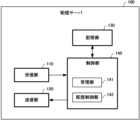
- FIG. 4 is a block diagram showing an example of a functional configuration of a distribution server
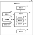
- FIG. 3 is a block diagram showing an example of a functional configuration of a distributor terminal according to Embodiment 1
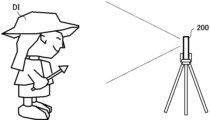
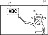
- FIG. FIG. 4 is a schematic diagram showing an example of how a distributor is photographed
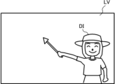
- FIG. 4 is a schematic diagram showing an example of a live video that is being shot
- FIG. 10 is a schematic diagram showing an example of a viewer video in which an object is combined with a live video
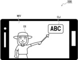
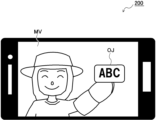
- FIG. 10 is a schematic diagram showing an example of a distributor's video in which an object is combined with a mirror image and displayed on the distributor's terminal;
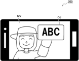
- FIG. 11 is a schematic diagram showing a state in which an object in a video for a distributor is pinched (pinch-out) by the distributor;
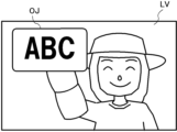
- FIG. 10 is a schematic diagram showing how the size of an object synthesized with a viewer-use video changes in response to a pinch operation by a distributor;
- FIG. 10 is a schematic diagram showing a state when an object in a video for a distributor is dragged by the distributor;
- FIG. 10 is a schematic diagram showing how the position of an object synthesized with a viewer-use video changes in response to a drag operation by a distributor; 5 is a flowchart for explaining distribution processing according to the first embodiment;
- FIG. 10 is a schematic diagram showing an example of the overall configuration of a live distribution system according to Embodiment 2 of the present disclosure; It is a block diagram showing an example of functional composition of a sales server.
- FIG. 11 is a block diagram showing an example of a functional configuration of a distributor terminal according to Embodiment 2;
- FIG. 4 is a schematic diagram showing an example of live video captured for live commerce;
- FIG. 10 is a schematic diagram showing an example of a viewer video in which a plurality of objects are combined with a live video;
- FIG. 10 is a schematic diagram showing an example of a distributor's video in which a plurality of objects are combined with a mirror image is displayed on the distributor's terminal;
- FIG. 4 is a schematic diagram showing an example of a viewer video displayed on a viewer terminal; It is a schematic diagram which shows an example of the sales page displayed on a viewer terminal.
- FIG. 1 is a schematic diagram showing an example of the overall configuration of a live distribution system 1 according to Embodiment 1 of the present disclosure.
- a distribution server 100 that manages distribution
- a distributor terminal 200 that is used by a distributor
- a viewer terminal 300 that is used by a viewer can communicate via the Internet 900. It is connected to the. It is assumed that a large number of viewer terminals 300 exist according to the number of viewers who use the system.
- the distribution server 100 is, for example, a server computer or the like, and manages the live distribution system 1 as a whole.
- the distribution server 100 receives a video (video for viewers, which will be described later) sent from the distributor terminal 200 and distributes it to the viewer terminal 300 .
- video video for viewers, which will be described later
- the following description assumes that video includes not only video data but also audio data.
- the distributor terminal 200 is, for example, a terminal such as a smartphone, tablet, or PC (Personal Computer), and is used by a distributor who distributes live video. As will be described later, the distributor takes an image of himself/herself from the image capturing unit (image capturing unit 210 described later) of the distributor terminal 200 and performs live distribution. At this time, a mirror image image obtained by inverting the captured live image is displayed on the display unit (display unit 260 described later), so the distributor checks his or her own actions while viewing the mirror image image.
- the distributor takes an image of himself/herself from the image capturing unit (image capturing unit 210 described later) of the distributor terminal 200 and performs live distribution. At this time, a mirror image image obtained by inverting the captured live image is displayed on the display unit (display unit 260 described later), so the distributor checks his or her own actions while viewing the mirror image image.
- the viewer terminal 300 is, for example, a terminal such as a smartphone, tablet, or PC, and is used by viewers who watch the live distribution. The viewer operates the viewer terminal 300 to log in to the distribution server 100 , and then views the live video distributed from the distributor terminal 200 via the distribution server 100 .
- the information processing device 400 includes a CPU (Central Processing Unit) 401, a ROM (Read Only Memory) 402, a RAM (Random Access Memory) 403, a NIC (Network Interface Card) 404, an image It includes a processing unit 405 , an audio processing unit 406 , an auxiliary storage unit 407 , an interface 408 , an imaging unit 409 , an operation unit 410 and a display unit 411 .
- a CPU Central Processing Unit
- ROM Read Only Memory
- RAM Random Access Memory
- NIC Network Interface Card
- the CPU 401 controls the operation of the entire information processing device 400, and is connected to each component to exchange control signals and data.
- the ROM 402 records an IPL (Initial Program Loader) that is executed immediately after the power is turned on. By executing this, the program stored in the auxiliary storage unit 407 is read out to the RAM 403, and the CPU 401 loads the program. Execution begins.
- IPL Initial Program Loader
- the RAM 403 is for temporarily storing data and programs, and holds programs and data read from the auxiliary storage unit 407, as well as other data necessary for communication.
- the NIC 404 is for connecting the information processing device 400 to a computer communication network such as the Internet. Consists of analog modems for connecting to the Internet using telephone lines, ISDN (Integrated Services Digital Network) modems, ADSL (Asymmetric Digital Subscriber Line) modems, cable modems for connecting to the Internet using cable television lines, etc. be done.
- ISDN Integrated Services Digital Network
- ADSL Asymmetric Digital Subscriber Line
- the image processing unit 405 processes the image data read from the auxiliary storage unit 407 or the like by the CPU 401 or an image arithmetic processor (not shown) included in the image processing unit 405, and then processes the image data in the image processing unit 405. Record in a frame memory (not shown).
- the image information recorded in the frame memory is converted into a video signal at a predetermined synchronization timing and output to the display unit 411 via the interface 408 or the like.
- the image processing unit 405 under the control of the CPU 401, the image processing unit 405 generates an image that is required in the course of the processing performed by the information processing device 400, and causes the display unit 411 to display the image.
- the audio processing unit 406 converts the music data and audio data read from the auxiliary storage unit 407 and the like into audio signals and outputs them to the outside via the interface 408 and the like. Note that when the information processing apparatus 400 includes a speaker inside, the audio processing unit 406 outputs the converted audio signal to the speaker. In other words, under the control of the CPU 401, the audio processing unit 406 generates music sounds and sounds to be generated during the processing performed by the information processing device 400, and outputs the music sounds and the like from internal or external speakers. Let
- the auxiliary storage unit 407 is a hard disk, SSD (Solid State Drive), or the like, and stores various programs and various data necessary for controlling the operation of the information processing apparatus 400 as a whole.
- the auxiliary storage unit 407 stores a program for implementing the distributor terminal 200 and the like according to the embodiment. Under the control of the CPU 401, the auxiliary storage unit 407 reads the stored programs and data as appropriate and temporarily stores them in the RAM 403 or the like.
- the interface 408 conforms to standards such as HDMI (registered trademark), USB (Universal Serial Bus), and I2C (Inter-Integrated Circuit), and is connected to the imaging unit 409, the operation unit 410, and the display unit 411. be done. Note that the interface 408 may transmit and receive necessary information to and from other connected external devices.
- the imaging unit 409 is, for example, a single-focal lens and an imaging device (CMOS: Complementary Metal Oxide Semiconductor or CCD: Charge Coupled Device) with a predetermined number of pixels, and shoots still images or moving images.
- CMOS Complementary Metal Oxide Semiconductor
- CCD Charge Coupled Device
- the operation unit 410 accepts operation input from a worker or the like who uses the information processing device 400 .
- the display unit 411 draws an image corresponding to the image data output by the image processing unit 405 and presents it to the operator or the like who uses the information processing device 400 .
- the information processing device 400 may be provided with a drive unit such as a DVD (Digital Versatile Disc)-ROM.
- the information processing device 400 reads programs and data from a DVD-ROM or the like mounted on the drive unit, and operates in the same manner as described above.
- FIG. 1 When the information processing device 400 is powered on, a program that functions as the distribution server 100 and the distributor terminal 200 according to the first embodiment is executed, and the distribution server 100 and the distributor terminal 200 according to the first embodiment are executed. is realized.
- the viewer terminal 300 is similarly realized by the information processing device 400, but since it has almost the same configuration as the distributor terminal 200, the explanation is omitted.
- FIG. 3 is a block diagram showing an example of the functional configuration of the distribution server 100.
- the distribution server 100 includes a receiver 110 , a transmitter 120 , a storage 130 and a controller 140 .
- the receiving unit 110 receives various information sent from the distributor terminal 200 and the viewer terminal 300 via the Internet 900 .
- the receiving unit 110 receives video (video for viewers, which will be described later) sent from the distributor terminal 200 .
- the receiving unit 110 receives a login request or the like from the viewer terminal 300 .
- the NIC 404 described above can function as such a receiving unit 110 .
- the transmission unit 120 transmits various information to the viewer terminal 300 and the like via the Internet 900.
- the transmission unit 120 is controlled by the control unit 140 (distribution control unit 142 described later) and distributes the video received from the distributor terminal 200 to the viewer terminal 300 .
- the NIC 404 described above can function as such a transmission unit 120 .
- the storage unit 130 stores various information necessary for processing in the distribution server 100 .
- the storage unit 130 stores IDs and passwords of viewers who use the viewer terminal 300 .
- the auxiliary storage unit 407 and the like described above can function as such a storage unit 130 .
- the control unit 140 controls the distribution server 100 as a whole.
- This control unit 140 includes, for example, a management unit 141 and a distribution control unit 142 .
- the management unit 141 collates the ID, password, etc. sent from the viewer terminal 300 requesting login with the ID, password, etc. stored in the storage unit 130 to authenticate the viewer.
- the distribution control unit 142 controls the receiving unit 110 and the transmitting unit 120 to distribute the video received from the distributor terminal 200 to the viewer terminal 300.
- the above-described CPU 401 and the like can function as the control unit 140 configured as described above.
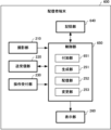
- FIG. 4 is a block diagram showing an example of the functional configuration of the distributor terminal 200 according to the first embodiment.
- the distributor terminal 200 includes an imaging unit 210 , a transmission/reception unit 220 , an operation reception unit 230 , a storage unit 240 , a control unit 250 and a display unit 260 .
- the photographing unit 210 is, for example, a camera arranged inside the distributor terminal 200 (on the display unit 260 side), and photographs the distributor.
- a distributor terminal 200 supported by a tripod or the like is arranged in front of the distributor DI to photograph the distributor DI. Then, the photographing unit 210 outputs the live video LV including the distributor DI as shown in FIG. Note that the imaging unit 409 described above can function as such an imaging unit 210 .
- the transmission/reception unit 220 transmits/receives various information to/from the distribution server 100 via the Internet 900 .
- the transmission/reception unit 220 is controlled by the control unit 250 (distribution unit 252, which will be described later), and transmits the viewer video, which will be described later, to the distribution server 100 (distributes it to the viewer terminal 300 via the distribution server 100).
- the NIC 404 described above can function as such a transmission/reception unit 220 .
- the operation reception unit 230 is a touch panel or pointing device (mouse, etc.) and receives various operations from the distributor.
- the operation accepting unit 230 accepts an operation directed to a distributor video (more specifically, an object described later) displayed on the display unit 260 .
- the operation unit 410 described above can function as such an operation reception unit 230 .
- the storage unit 240 stores various information necessary for processing in the distributor terminal 200.
- the storage unit 240 stores information about an object to be synthesized with a live video or the like, a synthesis position of the object, and the like.
- the object is a caption (banner) containing character information for notifying viewers in live distribution.
- the compositing position is the position where the object is composited in the live video. In other words, the combining position is defined with reference to the live video.
- the auxiliary storage unit 407 and the like described above can function as such a storage unit 240 .
- the control unit 250 controls the distributor terminal 200 as a whole.
- the control unit 250 includes, for example, a generation unit 251, a distribution unit 252, and a change unit 253.
- the generating unit 251 generates a video for viewers by combining objects at predetermined combining positions in the live video captured by the capturing unit 210 .
- the generation unit 251 generates a viewer video in which the object OJ is combined with the live video LV as shown in FIG.
- FIG. 7 shows a case where an object OJ including simple character information "ABC" is synthesized, but this is for the purpose of facilitating the explanation. to synthesize an object OJ containing necessary character information.
- the generation unit 251 generates a video for the distributor by synthesizing an object with a mirror image image obtained by inverting the live video. Note that the position where the object is synthesized with the mirror image is different from the above-described synthesis position. That is, the generation unit 251 synthesizes the object at the mirror image position with respect to the synthesis position in the mirror image video. For example, the generating unit 251 generates a broadcaster video by combining the object OJ with the mirror image video MV, as shown in FIG. It should be noted that FIG. 8 shows how the video for the distributor is displayed on the display unit 260 .
- the distributor DI can normally read the character information of the object OJ synthesized with the mirror image MV displayed on the display unit 260, and by pointing to the object OJ normally, the above-described figure can be read. 7, the object OJ is also pointed correctly. As a result, it is possible to appropriately support the distributor performing live distribution.
- the distribution unit 252 transmits the viewer video generated by the generation unit 251 to the distribution server 100 for distribution to the viewer terminal 300 . That is, the distribution unit 252 controls the transmission/reception unit 220 to transmit the viewer video as shown in FIG. Distribute video.
- the changing unit 253 changes the display mode of the object to be combined with the live video and the mirror image video according to the distributor's operation on the object in the video for the distributor. For example, the changing unit 253 changes the size of the object OJ in response to a pinch operation on the object OJ in the video for distributor shown in FIG. 8 displayed on the display unit 260 . Specifically, when the operation accepting unit 230 accepts a pinch-out to the object OJ by the distributor (an operation in which the object OJ is pressed with two fingers and spreads the fingers), the changing unit 253 causes the operation accepting unit 230 to As shown in 9, the size of the object OJ is enlarged.
- the change unit 253 changes the object OJ. reduce size.
- the changing unit 253 also updates the object information stored in the storage unit 240 . For example, as shown in FIG. 9, when the size of the object OJ is increased, the changing unit 253 also increases the value of the object information (eg, display magnification) in the storage unit 240 .
- the above-described generation unit 251 enlarges the size of the object and synthesizes it with the live video as well. That is, as shown in FIG.
- the generation unit 251 generates the viewer video by combining the object OJ whose size is enlarged with the live video LV. After the distributor releases the finger, the generation unit 251 generates the video for the distributor by synthesizing the object OJ with the mirror image video MV according to the updated object information and the like. , the enlarged object OJ will be maintained.
- changing the display mode of the object according to such an operation from the distributor is not limited to the size of the object.
- the changing unit 253 may change any of the shape, color, pattern, brightness, and brightness of the object according to the operation from the distributor.
- the distributor can directly operate the object in the mirror image displayed on the display unit 260 during the distribution to change the display mode of the object according to the intention.
- the changing unit 253 changes the object to be synthesized with the live video to the position of the normal image with respect to the new position. For example, when the operation reception unit 230 receives a drag operation to the object OJ (an operation to move the object OJ while pressing it with a finger), the change unit 253 performs the drag operation on the object OJ as shown in FIG. Move to a new position according to It should be noted that the changing unit 253 also updates the compositing position of the object stored in the storage unit 240 when the object OJ in the distributor video is moved.
- the changing unit 253 changes the composition position to the position of the normal image with respect to the new position of the object OJ moved in the video for distributor.
- the generation unit 251 generates a viewer video in which the object OJ is appropriately moved and combined with the live video LV. Then, after the distributor releases his/her finger, the generation unit 251 generates video for the distributor by synthesizing the object OJ at the mirror image position of the mirror image video MV with respect to the updated synthesis position.
- the position of the moved object OJ is also maintained in the human image. In this way, the distributor can directly operate the object in the mirror image displayed on the display unit 260 during distribution to freely move the object.
- the display unit 260 displays the video for the distributor generated by the generation unit 251 and the like. That is, the display unit 260 displays the images for the distributor as shown in FIGS. 8, 9, and 11 described above.
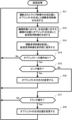
- FIG. 13 is a flowchart for explaining distribution processing according to the first embodiment. This distribution process starts when the distributor starts live distribution, and ends when the live distribution ends. In other words, the distribution process is executed by the distributor terminal 200 while the live distribution is being performed.
- the distributor terminal 200 generates a video for viewers in which an object is synthesized at the synthesis position of the shot live video (step S11). That is, the control unit 250 (generating unit 251) generates a viewer image obtained by synthesizing the object OJ with the live image LV as shown in FIG. Generate.
- the distributor terminal 200 generates a video for the distributor by synthesizing the object at the position of the mirror image with respect to the synthesis position in the mirror image (step S12). That is, the control unit 250 (generating unit 251) performs distribution in which the object OJ is synthesized with the mirror image video MV as shown in FIG. generate a video for the user.
- the distributor terminal 200 distributes the video for viewers and displays the video for the distributor on the display unit 260 (step S13). That is, the control unit 250 (distribution unit 252 ) transmits the viewer video generated in step S ⁇ b>11 described above to the distribution server 100 for distribution to the viewer terminal 300 . That is, the control unit 250 controls the transmitting/receiving unit 220 to transmit the viewer video as shown in FIG. Distribute video.
- the display unit 260 displays the image for the distributor generated in step S12 described above. That is, the display unit 260 displays the image for the distributor as shown in FIG. 8 described above.
- the distributor DI can normally read the character information of the object OJ that is combined with the mirror image MV, and by pointing to the object OJ normally, in the viewer video of FIG. Object OJ will be correctly pointed to. As a result, it is possible to appropriately support the distributor performing live distribution.
- the distributor terminal 200 determines whether or not an object has been operated (step S14). That is, the control unit 250 determines whether or not the operation accepting unit 230 has accepted an operation directed to an object in the video for the distributor displayed on the display unit 260 .
- step S14 determines that the object has not been operated (step S14; No)
- the process returns to step S11 described above.
- step S14 when it is determined that an object has been operated (step S14; Yes), the distributor terminal 200 determines whether or not the operation is a pinch operation (step S15).
- step S15 When the distributor terminal 200 determines that it is a pinch operation (step S15; Yes), it changes the size of the object (step S16). That is, the control unit 250 (change unit 253) changes the size of the object according to the pinch operation on the object in the video for distributor. Specifically, if the object is pinched out, the control unit 250 enlarges the size of the object OJ as shown in FIG. 9 described above. Conversely, when pinching in on an object, the control unit 250 reduces the size of the object. Note that when the size of the object in the distributor video is changed, the control unit 250 also updates the object information stored in the storage unit 240 . For example, as shown in FIG.
- the control unit 250 when the size of the object OJ is increased, the control unit 250 also increases the value of the object information in the storage unit 240.
- FIG. 10 the control unit 250 enlarges the size of the object and synthesizes it with the live video as well. That is, as shown in FIG. 10 described above, the control unit 250 generates a video for viewers by synthesizing the enlarged object OJ with the live video LV. After the distributor releases his/her finger, the control unit 250 generates a video for the distributor by synthesizing the object with the mirror image in accordance with the updated object information. Enlarged objects will be kept.
- the distributor terminal 200 After changing the size of the object in this way, the distributor terminal 200 returns the processing to step S11 described above.
- step S15 determines whether or not the operation is a drag operation (step S17).
- step S17 When the distributor terminal 200 determines that it is not a drag operation (step S17; No), the process returns to step S11 described above.
- the distributor terminal 200 changes the object synthesis position (step S18). That is, as shown in FIG. 11, the control unit 250 (change unit 253) moves the object OJ in the distributor video to a new position according to the drag operation. It should be noted that the control unit 250 also updates the synthesis position of the object stored in the storage unit 240 when moving the object OJ in the video for the distributor. Specifically, the control unit 250 changes the composition position to the position of the normal image with respect to the new position of the object OJ moved in the distributor video.
- control unit 250 (generating unit 251) generates a viewer video in which the object OJ is appropriately moved and combined with the live video LV, as shown in FIG. Then, after the distributor releases the finger, the control unit 250 generates a video for the distributor by synthesizing the object at the position of the mirror image in the mirror image of the updated synthesis position. The position of the moved object is maintained in the video as well.
- the distributor terminal 200 After changing the composition position of the object in this way, the distributor terminal 200 returns the processing to step S11 described above.
- the object OJ is synthesized at an appropriate position in the mirror image MV.
- the object OJ is also correctly pointed to in the viewer video of FIG. As a result, it is possible to appropriately support the distributor performing live distribution.
- the distributor can directly operate the object in the mirror image displayed on the display unit 260 during distribution to change the display mode of the object according to the intention.
- the object in the mirror image displayed on the display unit 260 can be directly manipulated during distribution to freely move the object.
- FIG. 14 is a schematic diagram showing an example of the overall configuration of the live distribution system 2 according to Embodiment 2 of the present disclosure.
- This live distribution system 2 is a system compatible with live commerce, and includes, for example, a distribution server 100 that manages distribution, a sales server 500 that manages sales, a distributor terminal 600 used by a distributor, A viewer terminal 300 used by the viewer is communicably connected via the Internet 900 .
- the distribution server 100 and the viewer terminal 300 have the same configuration as the distribution server 100 and the viewer terminal 300 in the live distribution system 1 of FIG. 1 described above. Also, it is assumed that a large number of viewer terminals 300 exist according to the number of viewers who use the system.
- the sales server 500 is, for example, a server computer or the like, and sells products introduced by the distributor during distribution from the distributor terminal 600 . More specifically, the product is sold to the viewer terminal 300 (viewer) who has transitioned according to transition information for transitioning to the sales server 500 (more specifically, product sales page).
- the distributor terminal 600 is, for example, a terminal such as a smartphone, tablet, or PC, and is used by a distributor who distributes live video. Distributor terminal 600 distributes to viewer terminal 300 a video for viewers in which an object (purchase button, which will be described later), etc. to which transition information for purchasing a product introduced in the distribution is added is synthesized with a live video. do.
- FIG. 15 When the information processing device 400 is powered on, a program that functions as the sales server 500 and the distributor terminal 600 according to the second embodiment is executed, and the sales server 500 and the distributor terminal 600 according to the second embodiment are executed. is realized.
- FIG. 15 is a block diagram showing an example of the functional configuration of the sales server 500. As shown in FIG. As illustrated, the sales server 500 includes a transmission/reception section 510, a storage section 520, and a control section 530. FIG.
- the transmitting/receiving unit 510 transmits/receives various information to/from the viewer terminal 300 via the Internet 900 .
- the transmitting/receiving unit 510 transmits a product sales page to the viewer terminal 300 in response to access from the viewer terminal 300 according to the transition information.
- the NIC 404 described above can function as such a transmission/reception unit 510 .
- the storage unit 520 stores various information necessary for processing in the sales server 500.
- the storage unit 520 stores detailed information, price information, and inventory information about products to be sold.
- the storage unit 520 also stores personal information (ID, name, address, credit card number, etc.) of the viewer using the viewer terminal 300 .
- the auxiliary storage unit 407 and the like described above can function as such a storage unit 520 .
- the control unit 530 controls the sales server 500 as a whole.
- the control unit 530 includes a sales processing unit 531, for example.
- the sales processing unit 531 confirms the sale of the product according to the operation from the viewer terminal 300 (viewer) who viewed the product sales page.
- the above-described CPU 401 and the like can function as the control unit 530 configured as described above.
- FIG. 16 is a block diagram showing an example of the functional configuration of the distributor terminal 600 according to the second embodiment.
- the distributor terminal 600 includes an imaging unit 210 , a transmission/reception unit 220 , an operation reception unit 230 , a storage unit 640 , a control unit 650 and a display unit 260 .
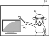
- the photographing unit 210, the transmitting/receiving unit 220, the operation receiving unit 230, and the display unit 260 are similar to the photographing unit 210, the transmitting/receiving unit 220, the operation receiving unit 230, and the display unit 260 in the distributor terminal 200 of FIG. It has the same configuration as Note that the photographing unit 210 outputs a live video LV including the product PD to be introduced and the distributor DI as shown in FIG. 17 .
- the storage unit 640 stores various information necessary for processing in the distributor terminal 600 .
- the storage unit 640 stores transition information for purchasing products introduced during distribution, in addition to information about objects to be combined with live video and the like, object combining positions, and the like.
- the transition information is link information to the sales page of the corresponding product in sales server 500 .
- the auxiliary storage unit 407 and the like described above can function as such a storage unit 640 .
- the control unit 650 controls the distributor terminal 600 as a whole.
- the control unit 650 includes an addition unit 651, a generation unit 251, a distribution unit 252, and a change unit 253, for example.
- the generating unit 251, the distributing unit 252, and the changing unit 253 have the same configuration as the generating unit 251, the distributing unit 252, and the changing unit 253 in the distributor terminal 200 (control unit 250) of FIG. .
- the addition unit 651 adds the transition information of the product being introduced during distribution to a specific object (purchase button, for example) stored in the storage unit 640 . Note that when the transition information of the product that has already been introduced has been added to the object, the adding unit 651 overwrites the transition information of the currently introduced product and adds it to the object. When an object to which such transition information is added is tap-operated on the viewer terminal 300 , it is possible to transition to the sales page of the corresponding product on the sales server 500 .
- the generation unit 251 generates a video for viewers by synthesizing necessary objects at predetermined synthesis positions in the live video shot by the shooting unit 210 .
- the generation unit 251 generates a viewer video in which the objects OJ1 and OJ2 are combined with the live video LV, as shown in FIG.
- the object OJ1 is a caption (banner) for explaining the product PD, and includes character information such as the product name and price.
- Object OJ2 is a purchase button, and includes text information of “purchase” and transition information added by the adding unit 651 .
- the generation unit 251 generates a video for the distributor by synthesizing an object with a mirror image image obtained by inverting the live video.
- the generation unit 251 generates a video for the distributor by combining the objects OJ1 and OJ2 with the mirror image video MV, as shown in FIG. do.
- FIG. 19 shows how the video for the distributor is displayed on the display unit 260 .
- the distributor DI can normally read the character information of the objects OJ1 and OJ2 synthesized with the mirror image MV displayed on the display unit 260, and can normally point to the objects OJ1 and OJ2.
- the objects OJ1 and OJ2 are correctly indicated in the above-described viewer video of FIG. 18 as well. As a result, it is possible to appropriately support the distributor performing live distribution.
- the changing unit 253 changes the display mode of the object to be combined with the live video and the mirror image according to the distributor's operation on the object in the distributor's video. Further, as in the first embodiment described above, when an object in the video for the distributor is moved to a new position by an operation from the distributor, the changing unit 253 moves the object to be synthesized with the live video to the new position. Change to the position of the normal image with respect to .
- FIG. 3 (Operation on viewer terminal 300) A viewer's operation on the viewer terminal 300 will be described below with reference to FIGS. 20 and 21.
- FIG. 20 A viewer's operation on the viewer terminal 300 will be described below with reference to FIGS. 20 and 21.
- the viewer's terminal 300 displays the viewer's video as shown in FIG. 20 on the display unit, for example. Then, when the viewer wishes to purchase the product PD introduced during the distribution, the viewer taps the object OJ2.
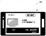
- the viewer terminal 300 accesses the sales server 500 according to the transition information added to the object OJ2, and displays the sales page SP as shown in FIG. 21 on the display unit. Note that the viewer terminal 300 may display an authentication screen for logging in to the sales server 500 before displaying the sales page. Then, when the purchase is confirmed on the sales page SP, the sale is completed.
- the distributor can normally transmit the character information of the objects OJ1 and OJ2 to be combined with the mirror image MV displayed on the display unit 260 as shown in FIG.
- the objects OJ1 and OJ2 are correctly pointed to in the viewer video of FIG.
- the control units 250 and 650 of the distributor terminals 200 and 600 include the generation unit 251 and the like, and the distributor terminals 200 and 600 synthesize the object with the live video and the mirror image video.
- the same configuration as the generation unit 251 and the like may be added to the control unit 140 of the distribution server 100 .
- the distribution server 100 synthesizes the object with the live video and the mirror image video, and the distributor terminals 200 and 600 display the video for the distributor returned from the distribution server 100 on the display unit 260 .
- the distributor can normally read the character information of the object synthesized with the mirror image displayed on the display unit 260, and by pointing to these objects normally, the viewer can , the object will be correctly pointed to. As a result, it is possible to appropriately support the distributor performing live distribution.
- Embodiments 1 and 2 above the case of synthesizing an object containing character information with a live video and a mirror image has been described. Appropriately applicable. Specifically, when synthesizing two bottle image objects into a live image and a mirror image image, the distributor checks the image of the objects and, as they are arranged, says, "The right side is the salt bottle, and the left side is the pepper bottle. It is possible to correctly explain such as
- the programs executed by the distributor terminals 200, 600, etc. are CD-ROM (Compact Disc Read Only Memory), DVD (Digital Versatile Disc), MO (Magneto-Optical Disk), USB It is also possible to distribute by storing in a computer-readable recording medium such as a memory or a memory card. By installing such a program on a specific or general-purpose computer, it is possible to make the computer function as the distributor terminals 200 and 600 in the first and second embodiments.
- the above program may be stored in a disk device possessed by a server device on a communication network such as the Internet, for example, superimposed on a carrier wave and downloaded to a computer.
- the above processing can also be achieved by starting and executing the program while transferring it via a communication network.
- the above processing can also be achieved by causing all or part of a program to be executed on a server device and executing the program while the computer transmits and receives information regarding the processing via a communication network.
- the distributor terminal characterized by: [4]
- the processor Further, when the object is moved to a new position in the video for the distributor by an operation from the distributor, the object synthesized with the live video is changed to a normal image position with respect to the new position.
- the distributor terminal according to any one of [1] to [3], characterized by: [5] Transition information for transitioning to a sales server that sells products is added to the object,
- the distributor terminal according to any one of [1] to [4], characterized by: [6] the object includes character information;
- a display method characterized by executing [8] to the computer, Transmission of viewer video for distribution to viewer terminals, which is a video in which an object is synthesized at a predetermined synthesis position
- the present disclosure can be suitably adopted for a distributor terminal, display method, and recording medium that can appropriately support the distributor.
Landscapes
- Engineering & Computer Science (AREA)
- Multimedia (AREA)
- Signal Processing (AREA)
- Physics & Mathematics (AREA)
- General Physics & Mathematics (AREA)
- Theoretical Computer Science (AREA)
- Software Systems (AREA)
- Databases & Information Systems (AREA)
- Business, Economics & Management (AREA)
- Marketing (AREA)
- Computer Security & Cryptography (AREA)
- Two-Way Televisions, Distribution Of Moving Picture Or The Like (AREA)
Abstract
Description
撮影部により撮影されているライブ映像内における所定の合成位置にオブジェクトを合成した映像であって、視聴者端末に向けた配信のための視聴者用映像の送信と、
前記ライブ映像を反転させた鏡像映像に前記オブジェクトを合成した映像であって、前記合成位置に対する鏡像の位置に前記オブジェクトを合成した配信者用映像の表示と、
を実行するプロセッサ、
を備えることを特徴とする。
前記プロセッサは、
前記配信者用映像内における前記オブジェクトに対する配信者からの操作に従って、前記ライブ映像及び前記鏡像映像に合成する前記オブジェクトについての表示態様の変更、を更に実行するようにしてもよい。
前記表示態様の変更には、前記オブジェクトの大きさ、形状、色彩、模様、明度、輝度の少なくとも1つの変更が含まれるようにしてもよい。
前記プロセッサは、
配信者からの操作によって前記配信者用映像内における前記オブジェクトが新たな位置へ移動されると、前記ライブ映像に合成する前記オブジェクトについての前記新たな位置に対する正像の位置への変更、を更に実行するようにしてもよい。
前記オブジェクトには、商品を販売する販売サーバへ遷移するための遷移情報が付加されていてもよい。
前記オブジェクトには、文字情報が含まれていてもよい。
コンピュータが、
撮影部により撮影されているライブ映像内における所定の合成位置にオブジェクトを合成した映像であって、視聴者端末に向けた配信のための視聴者用映像の送信と、
前記ライブ映像を反転させた鏡像映像に前記オブジェクトを合成した映像であって、前記合成位置に対する鏡像の位置に前記オブジェクトを合成した配信者用映像の表示と、
を実行することを特徴とする。
コンピュータに、
撮影部により撮影されているライブ映像内における所定の合成位置にオブジェクトを合成した映像であって、視聴者端末に向けた配信のための視聴者用映像の送信、
前記ライブ映像を反転させた鏡像映像に前記オブジェクトを合成した映像であって、前記合成位置に対する鏡像の位置に前記オブジェクトを合成した配信者用映像の表示、
を実行させるためのプログラムを記録したことを特徴とする。
図1は、本開示の実施形態1に係るライブ配信システム1の全体構成の一例を示す模式図である。このライブ配信システム1は、一例として、配信を管理する配信サーバ100と、配信者に使用される配信者端末200と、視聴者に使用される視聴者端末300とがインターネット900を介して通信可能に接続されている。なお、視聴者端末300は、システムを利用する視聴者の数に応じて、多数存在しているものとする。
本開示の実施形態1に係る配信サーバ100、及び、配信者端末200等が実現される典型的な情報処理装置400について説明する。
図3は、配信サーバ100の機能構成の一例を示すブロック図である。図示するように、配信サーバ100は、受信部110と、送信部120と、記憶部130と、制御部140とを備える。
図4は、実施形態1に係る配信者端末200の機能構成の一例を示すブロック図である。図示するように、配信者端末200は、撮影部210と、送受信部220と、操作受付部230と、記憶部240と、制御部250と、表示部260とを備える。
以下、配信者端末200の動作について図13を参照して説明する。図13は、実施形態1に係る配信処理を説明するためのフローチャートである。この配信処理は、配信者によるライブ配信が開始されると開始され、ライブ配信が終了すると終了する。つまり、配信処理は、ライブ配信が行われている間に渡って配信者端末200にて実行される。
上記の実施形態1では、シンプルなライブ配信システム1について説明したが、ライブコマースに対応したライブ配信システムであってもよい。以下、ライブコマースに対応したライブ配信システムについて説明する。
図15は、販売サーバ500の機能構成の一例を示すブロック図である。図示するように、販売サーバ500は、送受信部510と、記憶部520と、制御部530とを備える。
図16は、実施形態2に係る配信者端末600の機能構成の一例を示すブロック図である。図示するように、配信者端末600は、撮影部210と、送受信部220と、操作受付部230と、記憶部640と、制御部650と、表示部260とを備える。なお、撮影部210、送受信部220、操作受付部230、及び、表示部260は、上述した図4の配信者端末200における撮影部210、送受信部220、操作受付部230、及び、表示部260と同じ構成である。なお、撮影部210は、図17に示すような紹介する商品PD、及び、配信者DIを含んだライブ映像LVを出力する。
以下、視聴者端末300での視聴者の操作について図20、及び、図21を参照して説明する。
上記の実施形態1,2では、配信者端末200,600の制御部250,650に生成部251等が含まれており、配信者端末200,600が、オブジェクトをライブ映像及び鏡像映像に合成する場合について説明したが、この生成部251等と同じ構成を配信サーバ100の制御部140に付加するようにしてもよい。この場合、配信サーバ100側で、オブジェクトをライブ映像及び鏡像映像に合成し、配信者端末200,600が、配信サーバ100から返される配信者用映像を表示部260に表示することになる。この場合も、配信者は、表示部260に表示される鏡像映像に合成されるオブジェクトの文字情報を普通に読むことができ、また、それらオブジェクトを普通に指し示すことで、視聴者用映像においても、オブジェクトが正しく指し示されることになる。この結果、ライブ配信を行っている配信者を適切に支援することができる。
撮影部により撮影されているライブ映像内における所定の合成位置にオブジェクトを合成した映像であって、視聴者端末に向けた配信のための視聴者用映像の送信と、
前記ライブ映像を反転させた鏡像映像に前記オブジェクトを合成した映像であって、前記合成位置に対する鏡像の位置に前記オブジェクトを合成した配信者用映像の表示と、
を実行するプロセッサ、
を備えることを特徴とする配信者端末。
[2]
前記プロセッサは、
前記配信者用映像内における前記オブジェクトに対する配信者からの操作に従って、前記ライブ映像及び前記鏡像映像に合成する前記オブジェクトについての表示態様の変更、を更に実行する、
ことを特徴とする[1]に記載の配信者端末。
[3]
前記表示態様の変更には、前記オブジェクトの大きさ、形状、色彩、模様、明度、輝度の少なくとも1つの変更が含まれる、
ことを特徴とする[2]に記載の配信者端末。
[4]
前記プロセッサは、
配信者からの操作によって前記配信者用映像内における前記オブジェクトが新たな位置へ移動されると、前記ライブ映像に合成する前記オブジェクトについての前記新たな位置に対する正像の位置への変更、を更に実行する、
ことを特徴とする[1]乃至[3]の何れか1つに記載の配信者端末。
[5]
前記オブジェクトには、商品を販売する販売サーバへ遷移するための遷移情報が付加されている、
ことを特徴とする[1]乃至[4]の何れか1つに記載の配信者端末。
[6]
前記オブジェクトには、文字情報が含まれている、
ことを特徴とする[1]乃至[5]の何れか1つに記載の配信者端末。
[7]
コンピュータが、
撮影部により撮影されているライブ映像内における所定の合成位置にオブジェクトを合成した映像であって、視聴者端末に向けた配信のための視聴者用映像の送信と、
前記ライブ映像を反転させた鏡像映像に前記オブジェクトを合成した映像であって、前記合成位置に対する鏡像の位置に前記オブジェクトを合成した配信者用映像の表示と、
を実行することを特徴とする表示方法。
[8]
コンピュータに、
撮影部により撮影されているライブ映像内における所定の合成位置にオブジェクトを合成した映像であって、視聴者端末に向けた配信のための視聴者用映像の送信、
前記ライブ映像を反転させた鏡像映像に前記オブジェクトを合成した映像であって、前記合成位置に対する鏡像の位置に前記オブジェクトを合成した配信者用映像の表示、
を実行させるためのプログラムを記録したコンピュータ読み取り可能な記録媒体。
100 配信サーバ
110 受信部
120 送信部
130 記憶部
140 制御部
141 管理部
142 配信制御部
200,600 配信者端末
210 撮影部
220 送受信部
230 操作受付部
240,640 記憶部
250,650 制御部
251 生成部
252 配信部
253 変更部
651 付加部
260 表示部
300 視聴者端末
400 情報処理装置
401 CPU
402 ROM
403 RAM
404 NIC
405 画像処理部
406 音声処理部
407 補助記憶部
408 インターフェース
409 撮影ユニット
410 操作ユニット
411 表示ユニット
500 販売サーバ
510 送受信部
520 記憶部
530 制御部
531 販売処理部
900 インターネット
Claims (8)
- 撮影部により撮影されているライブ映像内における所定の合成位置にオブジェクトを合成した映像であって、視聴者端末に向けた配信のための視聴者用映像の送信と、
前記ライブ映像を反転させた鏡像映像に前記オブジェクトを合成した映像であって、前記合成位置に対する鏡像の位置に前記オブジェクトを合成した配信者用映像の表示と、
を実行するプロセッサ、
を備えることを特徴とする配信者端末。 - 前記プロセッサは、
前記配信者用映像内における前記オブジェクトに対する配信者からの操作に従って、前記ライブ映像及び前記鏡像映像に合成する前記オブジェクトについての表示態様の変更、を更に実行する、
ことを特徴とする請求項1に記載の配信者端末。 - 前記表示態様の変更には、前記オブジェクトの大きさ、形状、色彩、模様、明度、輝度の少なくとも1つの変更が含まれる、
ことを特徴とする請求項2に記載の配信者端末。 - 前記プロセッサは、
配信者からの操作によって前記配信者用映像内における前記オブジェクトが新たな位置へ移動されると、前記ライブ映像に合成する前記オブジェクトについての前記新たな位置に対する正像の位置への変更、を更に実行する、
ことを特徴とする請求項1に記載の配信者端末。 - 前記オブジェクトには、商品を販売する販売サーバへ遷移するための遷移情報が付加されている、
ことを特徴とする請求項1に記載の配信者端末。 - 前記オブジェクトには、文字情報が含まれている、
ことを特徴とする請求項1に記載の配信者端末。 - コンピュータが、
撮影部により撮影されているライブ映像内における所定の合成位置にオブジェクトを合成した映像であって、視聴者端末に向けた配信のための視聴者用映像の送信と、
前記ライブ映像を反転させた鏡像映像に前記オブジェクトを合成した映像であって、前記合成位置に対する鏡像の位置に前記オブジェクトを合成した配信者用映像の表示と、
を実行することを特徴とする表示方法。 - コンピュータに、
撮影部により撮影されているライブ映像内における所定の合成位置にオブジェクトを合成した映像であって、視聴者端末に向けた配信のための視聴者用映像の送信、
前記ライブ映像を反転させた鏡像映像に前記オブジェクトを合成した映像であって、前記合成位置に対する鏡像の位置に前記オブジェクトを合成した配信者用映像の表示、
を実行させるためのプログラムを記録したコンピュータ読み取り可能な記録媒体。
Priority Applications (4)
| Application Number | Priority Date | Filing Date | Title |
|---|---|---|---|
| US17/783,933 US12477157B2 (en) | 2022-02-16 | 2022-02-16 | Streamer terminal, display method, and non-transitory computer readable medium for displaying video during live streaming |
| PCT/JP2022/006174 WO2023157124A1 (ja) | 2022-02-16 | 2022-02-16 | ライブ配信中に映像を表示する配信者端末、表示方法、および、記録媒体 |
| JP2024500767A JP7583975B2 (ja) | 2022-02-16 | 2022-02-16 | ライブ配信中に映像を表示する配信者端末、表示方法、および、プログラム |
| JP2024192789A JP7844590B2 (ja) | 2022-02-16 | 2024-11-01 | ライブ配信中に映像を表示する配信者端末、表示方法、および、プログラム |
Applications Claiming Priority (1)
| Application Number | Priority Date | Filing Date | Title |
|---|---|---|---|
| PCT/JP2022/006174 WO2023157124A1 (ja) | 2022-02-16 | 2022-02-16 | ライブ配信中に映像を表示する配信者端末、表示方法、および、記録媒体 |
Publications (1)
| Publication Number | Publication Date |
|---|---|
| WO2023157124A1 true WO2023157124A1 (ja) | 2023-08-24 |
Family
ID=87577821
Family Applications (1)
| Application Number | Title | Priority Date | Filing Date |
|---|---|---|---|
| PCT/JP2022/006174 Ceased WO2023157124A1 (ja) | 2022-02-16 | 2022-02-16 | ライブ配信中に映像を表示する配信者端末、表示方法、および、記録媒体 |
Country Status (3)
| Country | Link |
|---|---|
| US (1) | US12477157B2 (ja) |
| JP (2) | JP7583975B2 (ja) |
| WO (1) | WO2023157124A1 (ja) |
Cited By (1)
| Publication number | Priority date | Publication date | Assignee | Title |
|---|---|---|---|---|
| JP7681781B1 (ja) * | 2024-09-19 | 2025-05-22 | PayPay株式会社 | 決済アプリケーションプログラム、情報処理装置、及び情報処理方法 |
Families Citing this family (1)
| Publication number | Priority date | Publication date | Assignee | Title |
|---|---|---|---|---|
| CN114125492B (zh) * | 2022-01-24 | 2022-07-15 | 阿里巴巴(中国)有限公司 | 直播内容生成方法以及装置 |
Citations (2)
| Publication number | Priority date | Publication date | Assignee | Title |
|---|---|---|---|---|
| JP2008054331A (ja) * | 2007-09-19 | 2008-03-06 | Toshiba Corp | 画像処理方法及びその装置 |
| JP2016509683A (ja) * | 2012-12-18 | 2016-03-31 | ヴィルコフスキー,ニッシ | 外観を撮像及び表示する装置、システム及び方法 |
Family Cites Families (5)
| Publication number | Priority date | Publication date | Assignee | Title |
|---|---|---|---|---|
| US8982109B2 (en) | 2005-03-01 | 2015-03-17 | Eyesmatch Ltd | Devices, systems and methods of capturing and displaying appearances |
| JP6313666B2 (ja) | 2014-06-06 | 2018-04-18 | 株式会社ソニー・インタラクティブエンタテインメント | 画像処理装置、画像処理方法及び画像処理プログラム |
| JP6305614B1 (ja) | 2017-09-04 | 2018-04-04 | 株式会社ドワンゴ | コンテンツ配信サーバ、コンテンツ配信方法およびコンテンツ配信プログラム |
| US10573077B2 (en) * | 2018-03-02 | 2020-02-25 | The Matilda Hotel, LLC | Smart mirror for location-based augmented reality |
| JP7068977B2 (ja) | 2018-09-11 | 2022-05-17 | 株式会社メルカリ | オンライン商取引支援システムにおける方法及びプログラム |
-
2022
- 2022-02-16 US US17/783,933 patent/US12477157B2/en active Active
- 2022-02-16 WO PCT/JP2022/006174 patent/WO2023157124A1/ja not_active Ceased
- 2022-02-16 JP JP2024500767A patent/JP7583975B2/ja active Active
-
2024
- 2024-11-01 JP JP2024192789A patent/JP7844590B2/ja active Active
Patent Citations (2)
| Publication number | Priority date | Publication date | Assignee | Title |
|---|---|---|---|---|
| JP2008054331A (ja) * | 2007-09-19 | 2008-03-06 | Toshiba Corp | 画像処理方法及びその装置 |
| JP2016509683A (ja) * | 2012-12-18 | 2016-03-31 | ヴィルコフスキー,ニッシ | 外観を撮像及び表示する装置、システム及び方法 |
Cited By (1)
| Publication number | Priority date | Publication date | Assignee | Title |
|---|---|---|---|---|
| JP7681781B1 (ja) * | 2024-09-19 | 2025-05-22 | PayPay株式会社 | 決済アプリケーションプログラム、情報処理装置、及び情報処理方法 |
Also Published As
| Publication number | Publication date |
|---|---|
| JP7844590B2 (ja) | 2026-04-13 |
| JPWO2023157124A1 (ja) | 2023-08-24 |
| US20240187655A1 (en) | 2024-06-06 |
| US12477157B2 (en) | 2025-11-18 |
| JP7583975B2 (ja) | 2024-11-14 |
| JP2025010376A (ja) | 2025-01-20 |
Similar Documents
| Publication | Publication Date | Title |
|---|---|---|
| US11778278B2 (en) | Server and method | |
| JP7844590B2 (ja) | ライブ配信中に映像を表示する配信者端末、表示方法、および、プログラム | |
| CN114442972B (zh) | 一种投屏方法及电子设备 | |
| WO2021218325A1 (zh) | 视频处理方法、装置、计算机可读介质和电子设备 | |
| WO2020077856A1 (zh) | 视频拍摄方法、装置、电子设备及计算机可读存储介质 | |
| JP7660312B2 (ja) | 配信システム、ライブ配信装置、ライブ配信方法及びプログラム | |
| CN116264603B (zh) | 直播信息处理方法、装置、设备和存储介质 | |
| US20240296195A1 (en) | System, method and computer-readable medium for recommendation | |
| US12393319B2 (en) | Display method, non-transitory readable storage medium, and chip | |
| US11025603B2 (en) | Service providing system, service delivery system, service providing method, and non-transitory recording medium | |
| US20240430490A1 (en) | Computer-readable storage medium, terminal, and server | |
| JP7633544B2 (ja) | プログラム、撮影装置 | |
| CN112514405A (zh) | 内容发布服务器、内容发布方法及程序 | |
| JP2025019816A (ja) | サーバおよびコンピュータプログラム | |
| US12348822B2 (en) | System, method and computer-readable medium for video processing | |
| US11722726B2 (en) | Television apparatus and display method | |
| TWI482472B (zh) | 多媒體內容傳播伺服器、多媒體內容傳播方法及相關的電腦程式產品 | |
| US12309217B2 (en) | System and method for playlist generation | |
| US20230297218A1 (en) | Terminal and method | |
| TW516312B (en) | Image conversion method | |
| CN120825607A (zh) | 一种图像处理方法、装置及存储介质 | |
| JP2025112215A (ja) | 撮影装置、及びプログラム | |
| CN105072334B (zh) | 一种数据处理方法及电子终端 | |
| JP2018101965A (ja) | 動画を配信するためのシステム、方法、及び、これらに用いられるプログラム | |
| CN113099552A (zh) | 可插拔设备及传屏方法 |
Legal Events
| Date | Code | Title | Description |
|---|---|---|---|
| WWE | Wipo information: entry into national phase |
Ref document number: 17783933 Country of ref document: US |
|
| 121 | Ep: the epo has been informed by wipo that ep was designated in this application |
Ref document number: 22927027 Country of ref document: EP Kind code of ref document: A1 |
|
| ENP | Entry into the national phase |
Ref document number: 2024500767 Country of ref document: JP Kind code of ref document: A |
|
| NENP | Non-entry into the national phase |
Ref country code: DE |
|
| 122 | Ep: pct application non-entry in european phase |
Ref document number: 22927027 Country of ref document: EP Kind code of ref document: A1 |
|
| WWG | Wipo information: grant in national office |
Ref document number: 17783933 Country of ref document: US |