WO2023153166A1 - 湾曲体マニピュレータおよび湾曲体ロボット - Google Patents
湾曲体マニピュレータおよび湾曲体ロボット Download PDFInfo
- Publication number
- WO2023153166A1 WO2023153166A1 PCT/JP2023/001643 JP2023001643W WO2023153166A1 WO 2023153166 A1 WO2023153166 A1 WO 2023153166A1 JP 2023001643 W JP2023001643 W JP 2023001643W WO 2023153166 A1 WO2023153166 A1 WO 2023153166A1
- Authority
- WO
- WIPO (PCT)
- Prior art keywords
- curved body
- linear
- linear member
- bending
- curved
- Prior art date
- Legal status (The legal status is an assumption and is not a legal conclusion. Google has not performed a legal analysis and makes no representation as to the accuracy of the status listed.)
- Ceased
Links
Images





















Classifications
-
- A—HUMAN NECESSITIES
- A61—MEDICAL OR VETERINARY SCIENCE; HYGIENE
- A61B—DIAGNOSIS; SURGERY; IDENTIFICATION
- A61B1/00—Instruments for performing medical examinations of the interior of cavities or tubes of the body by visual or photographical inspection, e.g. endoscopes; Illuminating arrangements therefor
- A61B1/005—Flexible endoscopes
- A61B1/008—Articulations
-
- B—PERFORMING OPERATIONS; TRANSPORTING
- B25—HAND TOOLS; PORTABLE POWER-DRIVEN TOOLS; MANIPULATORS
- B25J—MANIPULATORS; CHAMBERS PROVIDED WITH MANIPULATION DEVICES
- B25J1/00—Manipulators positioned in space by hand
- B25J1/02—Manipulators positioned in space by hand articulated or flexible
-
- B—PERFORMING OPERATIONS; TRANSPORTING
- B25—HAND TOOLS; PORTABLE POWER-DRIVEN TOOLS; MANIPULATORS
- B25J—MANIPULATORS; CHAMBERS PROVIDED WITH MANIPULATION DEVICES
- B25J11/00—Manipulators not otherwise provided for
-
- B—PERFORMING OPERATIONS; TRANSPORTING
- B25—HAND TOOLS; PORTABLE POWER-DRIVEN TOOLS; MANIPULATORS
- B25J—MANIPULATORS; CHAMBERS PROVIDED WITH MANIPULATION DEVICES
- B25J17/00—Joints
- B25J17/02—Wrist joints
-
- B—PERFORMING OPERATIONS; TRANSPORTING
- B25—HAND TOOLS; PORTABLE POWER-DRIVEN TOOLS; MANIPULATORS
- B25J—MANIPULATORS; CHAMBERS PROVIDED WITH MANIPULATION DEVICES
- B25J18/00—Arms
- B25J18/06—Arms flexible
-
- B—PERFORMING OPERATIONS; TRANSPORTING
- B25—HAND TOOLS; PORTABLE POWER-DRIVEN TOOLS; MANIPULATORS
- B25J—MANIPULATORS; CHAMBERS PROVIDED WITH MANIPULATION DEVICES
- B25J3/00—Manipulators of leader-follower type, i.e. both controlling unit and controlled unit perform corresponding spatial movements
- B25J3/02—Manipulators of leader-follower type, i.e. both controlling unit and controlled unit perform corresponding spatial movements involving a parallelogram coupling of the leader and follower units
-
- G—PHYSICS
- G02—OPTICS
- G02B—OPTICAL ELEMENTS, SYSTEMS OR APPARATUS
- G02B23/00—Telescopes, e.g. binoculars; Periscopes; Instruments for viewing the inside of hollow bodies; Viewfinders; Optical aiming or sighting devices
- G02B23/24—Instruments or systems for viewing the inside of hollow bodies, e.g. fibrescopes
Definitions
- the present invention relates to a curved body manipulator having a curved portion curved by a linear member, and a curved body robot having the curved manipulator.
- a bending portion is provided near the distal end of an elongated bending body manipulator, and the bending portion is bent by pushing and pulling a linear member such as a wire.
- a linear member such as a wire
- US Patent Application Publication No. 2021/0121051 discloses a configuration in which a bending body is bent by a wire. Specifically, one end of the wire is connected to the bending body and the other end is connected to the drive rod. A force is applied to the driving rod, and the bending body is bent by the driving rod moving the wire. A drive rod is positioned offset from the center of the flexure, and a wire is bent between the flexure and the drive rod along a groove in the cylinder and connected to the drive rod.
- the connecting member connected to the linear member receives a force to move the linear member and bend the bending portion
- the bending of the linear member may affect the bending operation of the bending portion due to the movement of the connecting member.
- the trajectory of the linear member and the frictional force generated between the linear member and the member that guides the linear member differ depending on whether the linear member is pushed or pulled.
- the relationship between the movement of the connecting member and the movement of the bending portion may differ depending on whether the linear member is pushed or pulled.
- One of the objects of the present invention is to suppress bending of the linear member between the connecting member and the curved body.
- a curved body including a curved portion; a guide member; a plurality of input units connected to the bending portion, each of which: (i) is connected to the bending portion, extends along a direction of extension, and bends the bending portion when moved along the direction of extension; (ii) a fixed portion to which the linear member is fixed; and a force receiving portion, the linear member is movable along a moving direction and perpendicular to the extending direction.
- a plurality of input units including a connecting member in which the force receiving portion is arranged at a position farther from the linear member than the fixing portion; has the connecting member is guided by the guide member and moved along the moving direction so that the linear member moves along the extending direction when the force receiving portion receives a force;
- a curved body including a curved portion and having a plurality of holes; a guide member; a plurality of input units connected to the bending portion, each of which: (i) is connected to the bending portion, extends along a direction of extension, and bends the bending portion when moved along the direction of extension; (ii) a fixed portion to which the linear member is fixed; and a force receiving portion, the linear member is movable along a moving direction and perpendicular to the extending direction.
- a plurality of input units including a connecting member in which the force receiving portion is arranged at a position farther from the linear member than the fixing portion; has the linear member has a fixed portion inserted into one of the plurality of holes and fixed to the fixing portion; the connecting member is guided by the guide member and moved along the moving direction so that the linear member moves along the extending direction when the force receiving portion receives a force;
- a curved body manipulator wherein the portion to be fixed and one of the plurality of holes at least partially overlap when viewed along the moving direction.
- the present invention can suppress bending of the linear member between the connecting member and the curved body.
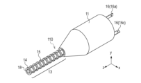
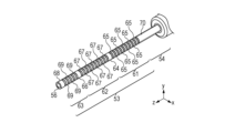
- FIG. 1 is a perspective view of a curved body manipulator according to Example 1.
- FIG. 1 is a perspective view of a curved body manipulator according to Example 1.
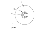
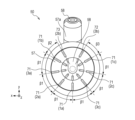
- FIG. 1 is a front view of a curved body manipulator according to Example 1.
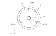
- FIG. 4 is a rear view of the curved body manipulator according to Example 1.
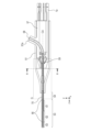
- FIG. 1 is a schematic cross-sectional view of a curved body manipulator according to Example 1;
- FIG. 4 is an enlarged view of the curved body manipulator according to Example 1.
- FIG. 4 is an enlarged view of the curved body manipulator according to Example 1.
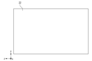
- FIG. 4 is a schematic front view of a central member according to Example 1.
- FIG. 4 is a schematic cross-sectional view of a central member according to Example 1.
- FIG. 4 is a schematic rear view of the central member according to Example 1.
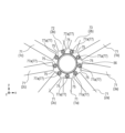
- FIG. 4 is a schematic front view of a tip member and a guide ring according to Example 1.
- FIG. 4 is a schematic side view of a tip member and a guide ring according to Example 1.
- FIG. 1 is a schematic front view of a tubular member according to Example 1.
- FIG. 1 is a schematic side view of a tubular member according to Example 1;
- FIG. 4 is a schematic front view of a connection member according to Example 1.
- FIG. 1 is a schematic side view of a connecting member according to Example 1.
- FIG. 1 is a schematic front view of a state in which a linear member according to Example 1 is joined to a connecting member;
- FIG. 4 is a schematic side view of a state in which the linear member according to Example 1 is joined to the connection member;
- FIG. 4 is an enlarged view of a state in which the linear member according to Example 1 is joined to the connection member;
- FIG. 4 is an enlarged view of a state in which the linear member according to Example 1 is joined to the connection member;
- FIG. 4 is a schematic perspective view of the curved body manipulator in a state where the bending portion according to the first embodiment is bent;
- FIG. 4 is a schematic cross-sectional view of the curved body manipulator with a curved portion according to the first embodiment;
- FIG. 11 is a schematic perspective view of a curved body manipulator according to Example 2;
- FIG. 11 is a schematic perspective view of a curved body manipulator according to Example 2;
- FIG. 11 is a schematic perspective view of a curved body manipulator according to Example 2;
- FIG. 4 is an enlarged view of a curved body manipulator;
- FIG. 11 is a schematic front view of a curved body manipulator according to Example 2;
- FIG. 11 is a schematic rear view of a curved body manipulator according to Example 2;
- FIG. 11 is a schematic cross-sectional view of a curved body manipulator according to Example 2;
- FIG. 11 is a schematic cross-sectional view of a curved body manipulator according to Example 2;
- FIG. 11 is an enlarged view of a curved body manipulator according to Example 2;
- FIG. 11 is a schematic perspective view of a curved body manipulator according to Example 2;
- FIG. 11 is a schematic perspective view of a curved body manipulator according to Example 2;
- FIG. 4 is an enlarged view of a curved body
- FIG. 11 is a schematic perspective view of a tubular member according to Example 2;
- FIG. 11 is a schematic front view of a tubular member according to Example 2;
- FIG. 11 is a schematic perspective view of each connection member according to Example 2;
- FIG. 11 is a schematic perspective view of each connection member according to Example 2;
- FIG. 11 is a schematic perspective view of each connection member according to Example 2;
- FIG. 10 is a schematic front view of each connection member in a state where hollow members are joined according to Example 2;
- FIG. 10 is a schematic front view of each connection member in a state where hollow members are joined according to Example 2;
- FIG. 10 is a schematic front view of each connection member in a state where hollow members are joined according to Example 2;
- FIG. 10 is a schematic front view of each connection member in a state where hollow members are joined according to Example 2;
- FIG. 10 is a schematic front view of each connection member in a state where hollow members are joined according to Example 2;
- FIG. 10 is
- Example 1 will be described with reference to FIGS. 1A and 1B to 10. FIG.
- FIG. 1A and 1B are schematic perspective views of the curved body manipulator 10.
- FIG. 1B the outer skin 12 of the curved body manipulator 10 is hidden.
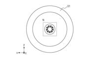
- FIG. 2A is a front view of the curved body manipulator 10, and is a view of the curved body manipulator 10 from the side of a curved body 110, which will be described later.
- FIG. 2B is a rear view of the curved body manipulator 10, and is a view of the curved body manipulator 10 from the side opposite to that of FIG. 2A.
- the curved body manipulator 10 includes a curved body 110 including a curved portion 13, an exterior member 11 as a frame to which the curved body 110 is attached, and a drive shaft 16 (16a, 16b, 16c).
- the curved body manipulator 10 according to this embodiment has three drive shafts 16 (16a, 16b, 16c) as a plurality of input units.
- a curved body can also be called a continuum
- a curved manipulator can also be called a continuum manipulator.
- the bending portion 13 includes a tip member 14 and a plurality of guide rings 15 , and the tip member 14 and the plurality of guide rings 15 are covered with the outer skin 12 .
- a central member 23 is accommodated inside the exterior member 11 .
- the curved body manipulator 10 has a hollow structure in which a through hole 18 is formed extending from the tip of the curved portion 13 to the rear end of the central member 23 in the z-axis direction.
- the three drive shafts 16a-16c can be driven independently of each other, and the bending portion 13 is bent by being slid in the z-axis direction manually or by an actuator. In other words, the bending of the bending portion 13 is controlled by the movement of each of the drive shafts 16a-16c, each having degrees of freedom in the z-axis direction.
- the end supported by the exterior member 10 is called the rear end.
- the curved body 110 is inserted into the object from the tip opposite to the rear end.
- the leading end can be called the distal end and the trailing end can be called the proximal end.
- FIG. 3A is a schematic cross-sectional view cut through the center of the curved body manipulator 10 and parallel to the yz plane.
- 3B is an enlarged view of the dashed line area A of FIG. 3A
- FIG. 3C is an enlarged view of the dashed line area B of FIG. 3A.
- the bending portion 13 has a tip member 14 and a plurality of guide rings 15 (nine in this embodiment) arranged at predetermined intervals.
- a tip member 14 is arranged at the tip of the bending portion 13 .
- the curved body 110 has a tubular member (longitudinal member) 22 having the same cross-sectional shape as the guide ring 15 .
- the tubular member 22 is arranged on the rear end (proximal end) side of the bending portion 13 at a predetermined distance from the guide ring 15 .
- Tubular member 22 is inserted into exterior member 11 , supported by exterior member 11 , and fixed to exterior member 11 .
- the curved body 110 has a cylindrical shape with a through hole 18 formed therein.
- the curved body 110 is cylindrical.
- the central axis of the curved body 110 be the central axis CA.
- the central axis CA coincides with the central axis of the curved body manipulator 10 .
- a plurality of drive shafts (16a to 16c) are arranged on the circumference so as to surround the central axis CA.
- Each of the drive shafts 16 a to 16 c has a flexible linear member 20 connected to the distal end member 14 of the bending portion 13 and a connecting member 21 connected to the linear member 20 .
- the connection member 21 is a member that is less likely to be deformed than the linear member 20 .
- the deformation of the connecting member 21 is smaller than that of the linear member 20 when the same force acts.
- the drive shafts 16a to 16c since the drive shafts 16a to 16c have the same structure, the drive shaft 16a will be described as a representative.
- the connection member (intermediate member) 21 has a joint portion (fixed portion) 21a and a force receiving portion 21b. As will be described later, the linear member 20 is inseparably fixed to the joint portion 21a.
- the connection member 21 is configured to be movable along the z-axis direction.
- the force receiving portion 21b is exposed outside the curved manipulator 10 (outside the exterior member 11).
- the connection member 21 is moved along the z-axis direction by the force receiving portion 21b receiving force (more specifically, external force transmitted from the outside of the curved body manipulator 10).
- the user can apply force to the force receiving portion 21b manually or using a driving source such as a motor.
- a portion of the linear member 20 fixed to the joint portion 21a can be called a joint portion (connection portion, fixed portion) 20a.
- connection member 21 integrally has the joint portion 21a, the force receiving portion 21b, and the connecting portion that connects the joint portion 21a and the force receiving portion 21b.
- Member 21 may be configured.
- the direction in which the linear member 20 extends is called the extending direction.
- the extending direction of the linear member 20 matches the longitudinal direction of the curved body 110 . In the state shown in FIGS. 3A and 3B (where the curved body 110 is straight), the extending direction of the linear member 20 coincides with the z-axis direction.
- the force receiving portion 21b is arranged at a position farther from the linear member 20 than the joining portion 21a in the direction perpendicular to the stretching direction (the y-axis direction in FIG. 3A).
- the joint portion 21a is arranged at a position closer to the central axis CA than the force receiving portion 21b.
- the linear member 20 By moving the connecting member 21 along the z-axis direction as the moving direction, the linear member 20 is integrally moved in the extending direction.
- the bending portion 13 is bent by moving the linear member 20 in the extending direction.
- the curved body manipulator 10 includes a plurality of drive shafts (16a-16c). Each drive shaft may also be identified by a number such as "first" or "second".
- the drive shaft 16a can be called a first drive shaft (first input section).
- the linear member 20 of the drive shaft 16a can be called a first linear member
- the connecting member 21 can be called a first connecting member.
- the extending direction of the first linear member is the first extending direction
- the moving direction of the first connecting member is the first moving direction
- the fixing portion of the first connecting member is the first fixing portion
- the force receiving portion of the first connecting member can be called a first force receiving portion.
- the drive shaft 16b can be called a second drive shaft (second input section) and the drive shaft 16c can be called a third drive shaft (third input section).
- FIG. 4A is a schematic front view of the central member 23
- FIG. 4B is a schematic cross-sectional view of the central member 23 taken along line EE
- FIG. 4C is a schematic rear view of the central member 23.
- the center member 23 is provided with radially extending grooves (guide grooves) 23a, 23b, 23c having a width W at intervals of 120 degrees, and a through hole 23d is provided in the center. Note that the center in the radial direction coincides with the central axis CA of the curved body 110 .
- the through hole 23 d forms part of the through hole 18 .
- the connecting members 21 of the respective drive shafts 16a to 16c are fitted into the grooves 23a, 23b and 23c.
- the groove 23a corresponds to the drive shaft 23a
- the groove 23b corresponds to the drive shaft 23b
- the groove 23c corresponds to the drive shaft 23c. 4A to 4C
- the grooves 23a are arranged along the y-axis direction. Since the grooves 23a, 23b, and 23c have the same shape, the groove 23a will be described as a representative.
- the groove 23a has a region L3 having a depth D1 and a region L4 having a depth D2 in the radial direction, where D1>D2.
- connection member 21 has a plate portion having a plate shape and has a plate thickness (thickness) slightly smaller than the groove width W.
- the joint portion 21a can move L1 in the positive z-axis direction and L2 in the negative z-axis direction from the neutral position.
- radial movement of the connecting member 21 is restricted by fitting the exterior member (cover member) 11 so as to cover the central member 23 23a, 23b, and 23c from the outside. Thereby, the movement of the connection member 21 in the circumferential direction (thickness direction) and radial direction is restrained.
- motion in the z-axis direction is limited to a predetermined range (L1+L2).
- the central member 23 and the exterior member 11 function as guide members that guide the connection member 21 . Therefore, the central member 23 can be called a first guide member, and the exterior member 11 can be called a second guide member.
- connection member 21 When the force receiving portion 21b receives force, the connection member 21 is guided by the central member 23 and the exterior member 11 and moved in the movement direction (z-axis direction in this embodiment). As a result, the linear member 20 fixed to the fixing portion 21a moves in the extending direction, and the bending portion 13 bends.
- the central member 23 and the exterior member 11 allow movement of the connection member 21 in the movement direction, while restricting movement of the connection member 21 in a direction crossing (preferably orthogonal to) the movement direction. Thereby, the connection member 21 is accurately moved in the moving direction.
- the central member 23 suppresses movement of the connecting member 21 in the circumferential direction around the central axis CA.
- the central member 23 suppresses the movement of the connection member 21 in the direction intersecting the extending direction of the linear member 20 and suppresses the bending of the linear member 22 .
- the central member 23 suppresses the rotation of the connection member 21 around the linear member 20 and suppresses the twisting of the linear member 20 .
- the exterior member 11 and the central member 23 suppress movement of the connecting member 21 in the radial direction about the central axis CA.
- the exterior member 11 and the central member 23 (the ends of the grooves 23a, 23b, and 23c) suppress the movement of the connecting member 21 in the direction intersecting with the extending direction of the linear member 20, thereby preventing the linear member 22 from bending ( flexion).
- connection member 21 is prevented from moving in the direction intersecting the moving direction, the linear member 20 is prevented from being bent.
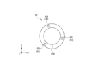
- FIG. 5A is a schematic front view of the tip member 14 and the guide ring 15
- FIG. 5B is a schematic side view of the tip member 14 and the guide ring 15.
- the tip member 14 and the guide ring 15 have an annular shape with a through hole 15d, and have three holes 15a, 15b, 15c at positions with the same radius r from the center.
- Linear members 20 of the drive shafts 16a to 16c are inserted into the three holes 15a, 15b, 15c, respectively.
- the through hole 15 d forms part of the through hole 18 .
- FIGS. 6A and 6B The tubular member 22 of the bending body 110 will be described with reference to FIGS. 6A and 6B.
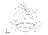
- 6A is a schematic front view of tubular member 22
- FIG. 6B is a schematic side view of tubular member 22.
- the tubular member 22 has an annular shape with a through hole 22d.
- the tubular member 22 is flexible and has three holes 22a, 22b, 22c at positions with the same radius r from its center.
- the linear members 20 of the drive shafts 16a-16c are inserted into the holes 22a-22c, respectively.
- the through hole 22 d forms part of the through hole 18 . It can also be said that the tubular member 22 is located at the proximal end of the curved body 110 and the holes 22 a - 22 c are also located at the proximal end of the curved body 110 .
- the other end (the end on the proximal end side) of the linear member 20 is joined to the connecting member 21 at the joining portion 21 a of the connecting member 21 .
- the linear member 20 of the drive shaft 16a is arranged so as to pass through the holes 14a, 15a and 22a of the tip member 14, the guide ring 15 and the tubular member 22, respectively.
- the linear member 20 of the drive shaft 16b is arranged so as to pass through the holes 14b, 15b and 22b of the tip member 14, the guide ring 15 and the tubular member 22, respectively.
- the linear member 20 of the drive shaft 16c is arranged to pass through the holes 14c, 15c and 22c of the tip member 14, the guide ring 15 and the tubular member 22, respectively.
- the curved body 110 has a tubular inner skin 19 and a tubular outer skin 12.
- Inner skin 19 and outer skin 12 are flexible.
- the tip member 14 and the guide ring 15 are arranged between the inner skin 19 and the outer skin 12 .
- the tip member 14 and the inner wall surface of the through hole 15 d of the guide ring 15 are joined to the outer peripheral surface (outer surface) of the inner skin 19 .
- the outer skin 12 is arranged on the outer peripheral surfaces (outer surfaces) of the tip member 14 and the guide ring 15 .
- Each of the linear members 20 of the drive shafts 16a to 16c has one end (end on the distal end side) fixed to the holes 15a to 15c of the tip member 14, passes through the holes 15a to 15c of the guide ring 15, and passes through the guide ring. It is arranged so as to be slidable with respect to fifteen holes.
- the linear member 20 passes through the holes 22a to 22c of the tubular member 22 toward the negative direction (proximal side) of the z-axis and reaches the interior of the exterior member 11.
- a connection member 21 is arranged inside the exterior member 11 .
- connection member 21 will be described with reference to FIGS. 7A and 7B.
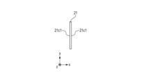
- 7A is a schematic front view of the connection member 21, and
- FIG. 7B is a schematic side view of the connection member 21.
- FIG. 7A is a schematic front view of the connection member 21, and
- FIG. 7B is a schematic side view of the connection member 21.
- connection member 21 has a plate portion (sheet portion) 21c having a plate shape (sheet shape).
- sheet portion 21c having a plate shape
- the entire connecting member 21 is the plate portion 21 c having a plate shape, but the plate portion 21 c may be a part of the connecting member 21 .
- the plate shape means that the length in the width direction (width, second length, first surface direction) is equal to the length in the thickness direction (thickness, second 1 length), and the length in the length direction (third length, second surface direction) is greater than or equal to the length in the width direction.
- the thickness of the plate-like portion of the connection member 21 in this embodiment, the entire connection member 21
- the thickness direction perpendicular to the thickness direction can be called the planar direction. 7A and 7B
- the thickness direction of the plate portion 21c of the connection member 21 is the x-axis direction
- the width direction is the y-axis direction
- the length direction is the z-axis direction.
- the connection member 21 has a surface (surface extending in the surface direction) 21c1 perpendicular to the thickness direction.
- the moving direction of the connecting member 21 is the z-axis direction, and the connecting member 21 is arranged so that the surface 21c1 extends along the moving direction.
- the central member 23 abuts on the pair of surfaces 21c1 in the groove 23 to guide the connecting member 21. As shown in FIG. In this manner, the central member 23 guides the surface 21c1, so that the connecting member 21 can move stably in the moving direction.
- connection member 21 has an L shape. As described above, the connection member 21 has the joint portion 21a and the force receiving portion 21b. In the moving direction (z-axis direction) of the connecting member 21, the force receiving portion 21b is arranged at a position away from the joint portion 21a (a position shifted with respect to the joint portion 21a).
- connection member 21 has a plate portion 21 c arranged near the linear member 20 .
- the joint portion 21a is arranged at the end of the plate portion 21c.
- the connection member 21 is arranged so that the surface 21c1 faces in the circumferential direction around the central axis CA, and the surfaces 21c1 are arranged radially from the central axis CA.
- connection members 21 of the drive shafts 16a to 16c becomes short. Can be placed close together in a small space. Further, the end of the plate portion 21c where the joint portion 21a is arranged has a flat plate shape. Therefore, the connection members 21 can be arranged close to each other in a smaller space.
- the joint portion 21a is arranged such that the linear member 20 extends linearly between the curved body 110 and the joint portion 21a.
- a portion of the linear member 20 located between the curved body 110 and the joint portion 21a can be called an intermediate portion 20b.
- the bending angle of the intermediate portion 20b of the linear member 20 is preferably within 10°, more preferably within 5°, with reference (0°) when the linear member 20 is perfectly straight.
- FIG. 6A is a diagram viewed along the moving direction of the connecting member 21, or a diagram viewed along the central axis CA or the extension direction of the linear member 20 in a state where the curved body 110 is straightened. can.
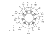
- the linear member 20 of each of the drive shafts 16a-16c is inserted into one of the plurality of holes (22a-22c) of the tubular member 22 of the bending body 110.
- the linear member 20 is inserted into a hole 22a, which is one of the plurality of holes (22a to 22c) of the tubular member 22 of the bending body 110.
- FIG. As shown in FIG. As shown in FIG.
- the hole 22a and the joint portion 21a of the drive shaft 16a, and the hole 22a and the fixed portion 20a of the drive shaft 16a at least partially overlap.
- the linear member 20 is bent between the bending body 110 and the joint portion 21a, when the connecting member 21 moves the linear member 20 in the moving direction via the joint portion 21a, one portion of the linear member 20 is bent.
- the portion (intermediate portion 20 b ) also moves in a direction intersecting with the extending direction of the linear member 20 . Further, the trajectory of the linear member 20 and the frictional force between the linear member 20 and the member that guides the linear member 20 differ depending on whether the connecting member 21 pushes the linear member 20 or pulls it.
- the linear member 20 extends straight from the joint portion 21a to the curved body 110, bending of the linear member 20 is suppressed. 20 is suppressed from moving in a direction crossing the stretching direction. In addition, it is possible to suppress the difference in the trajectory of the linear member 20 and the frictional force between the linear member 20 and the member that guides the linear member 20 depending on whether the connecting member 21 pushes the linear member 20 or pulls it. be.
- the bending portion 13 is bent by moving the linear member 20 in the extending direction. It can be bent efficiently and accurately.
- FIG. 8A is a schematic front view of the linear member 20 joined to the connecting member 21
- FIG. 8B is a schematic side view of the linear member 20 joined to the connecting member 21, and FIG.
- FIG. 8D is an enlarged view of the dashed line area F.
- FIG. Note that the configuration shown in FIG. 8D is a modification of the configuration shown in FIG. 8C.
- the fixed portion 20a of the linear member 20 is joined to the joining portion (connecting portion, fixed portion) 21a of the connecting member 21.
- the joining material 24 can join them more firmly.
- connection member 21 can be made of metal such as iron, stainless steel, copper, or aluminum alloy, resin such as polycarbonate, PEEK (polyetheretherketone), or ABS, or ceramics such as alumina or zirconia.
- resin such as polycarbonate, PEEK (polyetheretherketone), or ABS, or ceramics such as alumina or zirconia.
- bonding material 24 an epoxy-based adhesive, an ultraviolet curing resin, or the like can be used.
- the connection member 21 is made of metal, the linear member 20 and the connection member 21 can be joined by welding or brazing. In this case, the joining material 24 can be weld metal or brazing material. can.
- connection member 21 and the linear member 20 can be joined as shown in FIG. 8D.
- a through-hole 21c is provided in the joint portion 21a of the connecting member 21 so as to penetrate the joint portion 21a in the z-axis direction, and the linear member 20 is inserted into the through-hole 21c to join the two.
- the linear member 20 may be fixed using an anaerobic adhesive or an instant adhesive, or the linear member 20 may be fixed by deforming the joint portion 21a. .
- the drive shafts 16a to 16c can be pushed and pulled independently of each other in the z-axis direction. can be done.
- FIG. 9 is a schematic perspective view of the curved body manipulator 10 with the bending portion 13 bent.
- FIG. 10 is a schematic cross-sectional view of the curved body manipulator 10 with the bending portion 13 bent.
- 10 is a cross-sectional view through the center of the curved body manipulator 10.
- the bending portion 13 can be bent within the yz plane while the curvature of the bending portion 13 is kept constant.
- Zo be the position of the end of each of the drive shafts 16a to 16c in the z-axis direction when the curved portion 13 is in a horizontal state (linear state)
- Za to Zc be displacements of the drive shafts 16a to 16c in the z-axis direction, respectively.
- the bending operation is realized by pulling the driving shaft 16a in the negative z-axis direction Za and pushing the driving shafts 16b and 16c in the positive z-axis direction Zb and Zc.
- the bending portion 13 of the bending body manipulator 10 of this embodiment has two degrees of freedom of bending and turning.
- connection member 21 it is possible to efficiently transmit the thrust force from the connection member 21 to the linear member 20 arranged at the curved portion 13 with the radius r.
- the linear member 20 is linearly arranged from the tubular member 22 to the joint portion (joint portion 21a) to the connection member 21.
- FIG. Therefore, the path when pushing the linear member 20 and the path when pulling the linear member 20 are the same, so there is a difference between the dynamic characteristics when pushing the linear member 20 and the dynamic characteristics when pulling the linear member 20 less likely to occur.
- the connecting member 21 is plate-shaped, it can be easily manufactured by machining, injection molding, die casting, press working, surface grinding, etc., and the connecting member 21 can slide smoothly with high accuracy. . Therefore, it is possible to reduce variations in control performance when pushing and pulling the linear member 20 .
- the configuration of this embodiment it is possible to easily transmit thrust to the linear member 20 arranged in a narrow space.
- the diameter of the outer skin 12 is about 5 mm
- the diameter of the inner skin 19 is about 3 mm
- the force receiving portion 21b for transmitting the force has a radius sufficiently larger than the radius r at which the linear member 20 is arranged. Can be placed on a circle.
- the actuators such as motors and handles are used to transmit thrust to the drive shafts 16a to 16c, the degree of freedom in designing the arrangement and size of the actuators such as motors and handles is improved, and the force applied to narrow spaces is improved. facilitates the transmission of
- the curved body manipulator 10 can use the through holes 18 to insert various tools from the central member 23 side toward the curved portion 13 .
- the linear member 20 and the actuator can be combined. It is possible to electrically insulate between
- insulation can be achieved by applying an alumite treatment to the vicinity of the force receiving portion 21b.
- curved body manipulator 110 when used in a medical device, forceps, a biopsy tool, etc. can be inserted into the through hole 18 in addition to the camera to perform medical treatment in a narrow space inside the body.
- the linear members 20 are linearly arranged, the risk of the linear members 20 buckling is reduced, and the frictional force accompanying the driving of the linear members 20 is reduced or reduced. can be stabilized.
- Friction force is set properly.
- the central member 23 and the connecting member 21 can slide smoothly.
- the central member 23 should be made of a resin material such as polyacetal having high slidability. is preferred. As a result, the magnitudes of the maximum static friction force and the dynamic friction force become close to each other, and the connecting member 21 is stably and slidably supported by the central member 23 .
- the bending portion 13 can move with two degrees of freedom of bending and turning in response to input with three degrees of freedom using the three drive shafts 16a to 16c.
- the bending portion 13 can be expanded and contracted in the z-axis direction. This provides a curved body manipulator 10 with a total of three degrees of freedom.
- Example 2 A curved body manipulator (continuous body manipulator) 50 according to the second embodiment will be described with reference to FIGS. 11A, 11B, 11C, 11D to 23A and 23B.
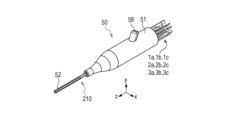
- FIG. 11A is a schematic perspective view of the curved body manipulator 50
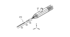
- FIG. 11B is a schematic perspective view of the curved portion 53 of the curved body manipulator 50 with the outer skin 52 hidden
- FIG. FIG. 11D is an enlarged view of the dashed line area C
- FIG. 12A is a schematic front view of the curved body manipulator 50
- FIG. 12B is a schematic rear view of the curved body manipulator 50
- FIG. FIG. 13 is a schematic cross-sectional view of the curved body manipulator 50 taken through the center of the curved body manipulator 50 and parallel to the yz plane.
- 14A is a schematic cross-sectional view of the curved body manipulator 50 taken along the line HH in FIG. 13, and FIG. 14B is an enlarged view of the broken line area I.
- FIG. 14A is a schematic cross-sectional view of the curved body manipulator 50 taken along the line HH in FIG. 13, and FIG. 14B is an enlarged view of the broken line area I.
- the curved body manipulator 50 includes a curved body 210 including a curved portion 53, an exterior member (frame) 51 to which the curved body 210 is attached, and drive shafts (1a, 1b) as input portions connected to the curved portion 53 of the curved body 210. , 1c, 2a, 2b, 2c, 3a, 3b, 3c).
- a curved body manipulator 50 according to this embodiment has nine drive shafts (input portions) 1a, 1b, 1c, 2a, 2b, 2c, 3a, 3b, and 3c as a plurality of drive shafts (input portions).
- the functions of the drive shafts 1a-1c, 2a-2c, 3a-3c are the same as the drive shafts 16a-16c of the first embodiment. That is, the drive shafts 1a to 1c, 2a to 2c, and 3a to 3c can be driven independently of each other, and the bending portion 53 is bent by being slid in the z-axis direction manually or by an actuator. . In other words, the bending of the bending portion 53 is controlled by the movement of the drive shafts 1a-1c, 2a-2c, 3a-3c each having degrees of freedom in the z-axis direction.
- the drive shafts 1a-1c, 2a-2c, 3a-3c have connecting members 71, 72, 73 corresponding to the connecting member 21 in the first embodiment.
- the drive shafts 1a to 1c, 2a to 2c, and 3a to 3c by pushing and pulling the connection members 71 to 73 in the z-axis direction, the linear member 77 corresponding to the linear member 20 in the first embodiment is stretched in the extending direction. driven.
- the curved portion 53 has three sections, a first section 61, a second section 62 and a third section 63. As shown in FIG. The configurations of the first section 61, the second section 62, and the third section 63 will be described in detail.
- the first section 61 has a tip member 64 and a plurality of guide rings 65 (nine in this embodiment) arranged at predetermined intervals.
- the second section 62 has a tip member 66 and a plurality of guide rings 67 (nine in this embodiment) arranged at predetermined intervals.
- the third section 63 has a tip member 68 and a plurality of guide rings 69 (four in this embodiment) arranged at predetermined intervals.
- tip members 64, 66, 68 and the guide rings 65, 67, 69 will be described with reference to FIGS. 16A to 16C and 17A to 17C.
- FIG. 16A is a schematic front view of the tip member 64
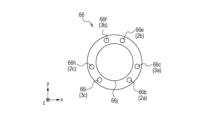
- FIG. 16B is a schematic front view of the tip member 66
- FIG. 16C is a schematic front view of the tip member 68
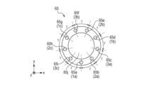
- 17A is a schematic front view of the guide ring 65
- FIG. 17B is a schematic front view of the guide ring 67
- FIG. 17C is a schematic front view of the guide ring 69.
- FIG. 17A is a schematic front view of the guide ring 65
- FIG. 17B is a schematic front view of the guide ring 67
- FIG. 17C is a schematic front view of the guide ring 69.
- the tip member 64 and the guide ring 65, the tip member 66 and the guide ring 67, the tip member 68 and the guide ring 69 have the same cross-sectional shape, and as shown in FIG. different.
- the tip member 64 has an annular shape with a through hole 64j, and nine holes 64a to 64i located at the same radius r from the center.
- the guide ring 65 has an annular shape with a through hole 65j, and nine holes 65a to 65i located at the same radius r from the center.
- the coordinate positions in the xy plane of the nine holes 65a-65i and the through hole 65j are the same as the coordinate positions in the xy plane of the holes 64a-64i and the through hole 64j.
- the tip member 66 has an annular shape with a through hole 66j, and has six holes 66b, 66c, 66e, 66f, 66h, 66i at the same radial position r from the center. have.
- the coordinate positions of the six holes 66b, 66c, 66e, 66f, 66h, 66i and the through hole 66j in the xy plane are and are the same as the respective coordinate positions in the xy plane of the through hole 64j.
- the guide ring 67 has an annular shape with a through hole 67j, and has six holes 67b, 67c, 67e, 67f, 67h, 67i at the same radial position r from the center. have.
- the coordinate positions in the xy plane of each of the six holes 67b, 67c, 67e, 67f, 67h, 67i and the through hole 67j are , are the same as the respective coordinate positions in the xy plane of the through hole 66j.
- the tip member 68 has an annular shape with a through hole 68j, and has three holes 68c, 68f, 68i at positions with the same radius r from the center.
- the coordinate positions in the xy plane of each of the three holes 68c, 68f, 68i and the through hole 68j are the coordinates in the xy plane of the holes 64c, 64f, 64i and the through hole 64j. It is the same as each coordinate position.
- the guide ring 69 has an annular shape with a through hole 69j, and has three holes 69c, 69f, 69i at positions with the same radius r from the center.
- the coordinate positions in the xy plane of each of the three holes 69c, 69f, 69i and the through hole 69j are each in the xy plane of the holes 69c, 69f, 69i and the through hole 69j. is the same as the coordinate position of
- the curved body 210 has a tubular member 70 adjacent to the curved portion 53 .
- the tubular member 70 is arranged so that a predetermined gap is created between it and the guide ring 65 .
- the tubular member 70 is made of a flexible material, and as shown in FIG. 13, is partially supported by the exterior member 51 to form the driven bending portion 54 of the bending body 210 .
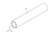
- FIG. 18A is a schematic perspective view of the tubular member 70
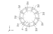
- FIG. 18B is a schematic front view of the tubular member 70
- the tubular member 70 of the curved body 210 has an annular cross-sectional shape with a through hole 70j, and nine holes 70a to 70i located at the same radius r from the center.
- the xy-plane coordinate positions of the nine holes 70a-70i and the through hole 70j are the same as the xy-plane coordinate positions of the holes 64a-64i and the through hole 64j.
- the tubular member 70 is arranged at the proximal end of the bending body 210, like the tubular member 22 in the first embodiment.
- the connecting members 71, 72, 73 have joint portions 71a, 72a, 73a to which the linear member 77 is fixed, and the linear member 77 is fixed to the joint portions 71a, 72a, 73a. It has a fixing portion 77a.
- the relationship between the joint portions 71a, 72a, 73a, the fixed portion 77a, and the nine holes 70a to 70i is the same as the relationship shown in the first embodiment.
- the curved body 210 has an inner skin 56 and an outer skin 52 that are tubular and flexible.
- the inner wall surfaces of the tip members 64 , 66 , 68 , the guide rings 65 , 67 , 69 and the through holes 64 j , 66 j , 68 j , 65 j , 67 j , 69 j , 70 j of the tubular member 70 are joined to the outer peripheral side surface of the inner skin 56 .
- the outer skin 52 is fixed to the outer peripheral side surface of the curved portion 53 including the tip members 64 , 66 , 68 and the guide rings 65 , 67 , 69 so as to partially cover the outer peripheral side surface of the tubular member 70 .
- linear members 77 In order to drive the first section 61, the second section 62 and the third section 63, nine linear members 77 are used, three for each section.
- one ends of the linear members 77 of the drive shafts 1a, 1b, 1c are fixed to the holes 64a, 64d, 64g of the tip member 64, respectively.
- Each linear member 77 is pushed and pulled in the z-axis direction.
- Each linear member 77 passes through the holes 65a, 65d, 65g of the guide ring 65 and the holes 70a, 70d, 70g of the tubular member 70 and is guided by these holes.
- each linear member 77 of the drive shafts 2a, 2b, 2c is fixed to the holes 66b, 66e, 66h of the tip member 66, respectively.
- Each linear member 77 is pushed and pulled in the z-axis direction.
- Each linear member 77 passes through holes 67b, 67e, 67h of the guide ring 67, holes 64b, 64e, 64h of the tip member 64 of the first section, and holes 65b, 65e, 65h of the guide ring 65 of the first section. and guided by these holes.
- Each linear member 77 passes through holes 70b, 70e, and 70h of tubular member 70 and is guided by these holes.
- one ends of the linear members 77 of the drive shafts 3a, 3b, 3c are fixed to the holes 68c, 68f, 68i of the tip member 68, respectively.
- Each linear member 77 is pushed and pulled in the z-axis direction.
- Each linear member 77 passes through holes 69c, 69f and 69i of the guide ring 69, holes 66c, 66f and 66i of the tip member 66 of the second section, and holes 67c, 67f and 67i of the guide ring 67 of the second section. and guided by these holes.
- the respective linear members 77 are provided with holes 64c, 64f, 64i of the tip member 64 of the first section, holes 65c, 65f, 65i of the guide ring 65 of the first section, and holes 70c, 70f, 70i of the tubular member 70. and guided by these holes.
- the first section 61 is provided with two degrees of freedom of bending and turning by the same mechanism as described in the first embodiment. It is possible to take action.
- the second and third sections 62 and 63 can be bent and turned with two degrees of freedom. That is, in this embodiment, the bending portion 53 functions as a manipulator with six degrees of freedom.
- the drive shaft 3b has a connection member 72 and the drive shaft 2b has a connection member 73.
- the other seven drive shafts (1a to 1c, 2a, 2c, 3a, 3c) have connecting members 71.
- the connection members 71 , 72 , 73 have different shapes, they have the same function as the connection member 21 of the first embodiment in terms of the function of moving the linear member 77 .
- connection members 71-73 corresponding to the drive shafts (1a-1c, 2a-2c, 3a-3c) is as shown in FIG. 14A.
- connection members 71, 72, and 73 Details of the connection members 71, 72, and 73 will now be described with reference to FIGS. 19A to 19F.
- 19A is a schematic perspective view of the connection member 71
- FIG. 19B is a schematic perspective view of the connection member 72
- FIG. 19C is a schematic perspective view of the connection member 73.
- FIG. 19D is a schematic front view of the connection member 71 to which the hollow member 75 is joined
- FIG. 19E is a schematic front view of the connection member 71 to which the hollow member 75 is joined
- FIG. 2 is a schematic front view of the connecting member 71.
- FIG. 19A is a schematic perspective view of the connection member 71
- FIG. 19B is a schematic perspective view of the connection member 72
- FIG. 19C is a schematic perspective view of the connection member 73.
- FIG. 19D is a schematic front view of the connection member 71 to which the hollow member 75 is joined
- FIG. 19E is a schematic front view of
- connection members 71 to 73 have joint portions 71a to 73a and force receiving portions 71b to 73b, respectively, like the connection member 21 of the first embodiment.
- the functions of the joint portions 71a to 73a are the same as those of the force receiving portion 21a in the first embodiment, and the functions of the force receiving portions 71b to 73b are the same as the force receiving portion 21b in the first embodiment.
- connection members 71, 72, 73 have plate portions 71c, 72c, 73c, similarly to the connection member 21 of the first embodiment having the plate portion 21c.
- the plate portion 71c has a plate shape (flat plate shape) parallel to the plane.
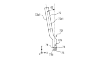
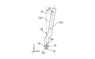
- the plate portions 72c and 73c of the connection members 72 and 73 are partially bent to form bent portions 72f and 73f.
- the connection members 72 and 73 have plate shapes bent at angles ⁇ 2 and ⁇ 3, respectively, with respect to the flat plate portions having joint portions 72a and 73a formed at the ends by bending the plate portions 72c and 73c.
- the connection members 72 and 73 are bent in opposite directions about the z-axis with respect to the yz plane.
- connection members 71 to 73 is provided with inclined portions 71d, 72d, and 73d, and each of the connection members 71 to 73 has a rectangular part, more specifically, an L-shaped corner that is notched. shape.
- the inclined portions 71d, 72d, and 73d are inclined toward the central axis CA from the proximal end to the distal end in the direction perpendicular to the central axis CA.
- the exterior member 51 has a tapered shape in accordance with this inclination.
- connection members 71 to 73 while securing the rigidity of the connection members 71 to 73 in the z-axis direction, it is possible to minimize the volume of the exterior member 51 considering the movement of the connection members 71 to 73 in the z-axis direction, thereby improving space efficiency. can be enhanced.
- connection members 71 to 73 is provided with inclined portions 71e to 73e obtained by cutting out a part of the rectangular shape. This makes it easy to avoid interference with the central member 57 when the connecting members 71 to 73 are driven in the negative direction of the z-axis.
- the curved body manipulator 50 has a central member 57 corresponding to the central member 23 in the first embodiment.
- the curved body manipulator 50 uses the central member 57 as a guide member to guide the connecting members 71 to 73 in the movement direction (z-axis direction). This makes it possible to stably transmit the thrust input to the force receiving portions 71b to 73b to the joint portions 71a to 73a.
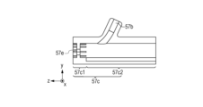
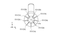
- FIG. 15A is a schematic perspective view of the central member 57
- FIG. 15B is a schematic cross-sectional view of a cutting plane passing through the center of the central member 57 and parallel to the yz plane
- FIG. 15C is a schematic front view of the central member 57
- 15D is a schematic rear view of central member 57.
- the central member 57 has nine grooves 57c having regions 57c1 and 57c2, an insertion port 57a with a through hole 57b on the side surface, and a support portion 57e for fitting and supporting a straight pipe 59, which will be described later.
- the groove 57c is provided along the radial direction. Regions 57c1 and 57c2 have different radial depths, with region 57c1 being deeper than region 57c2.
- the connection members 71, 72 and 73 are fitted into the regions 57c1 and 57c2 of the groove 57c, and the distal end sides of the connection members 71, 72 and 73 where the joint portions 71a to 73a are arranged are aligned in the z-axis direction by the region 57c1. be guided.
- the connecting members 71 , 72 , 73 are slidably supported by the central member 57 at surfaces 71 c 1 , 72 c 1 , 73 c 1 perpendicular to the thickness direction.
- the gap between the width of the groove 57c and the connecting members 71, 72, 73 and the material of the central member 57 and the connecting members 71, 72, 73 are determined by the central member 57. It is designed to be smoothly guided. Further, as in the first embodiment, by covering the side surface of the central member 57 with the inner wall of the exterior member 51, the connecting members 71 to 73 are constrained so as not to move in the radial direction.
- a hollow member 75 is joined to the joining portions 71a to 73a of the connection members 71 to 73 with a joining material 74 interposed therebetween.
- the hollow member 75 is a hollow linear member having a through hole 75a therein, and is a pipe made of metal such as stainless steel or a tube made by extrusion molding of plastic.
- a method for joining the connection members 71 to 73 and the hollow member 75 is the same as the method for joining the connection member 21 and the linear member 20 of the first embodiment, and detailed description thereof is omitted here.
- Each linear member 70 is fixed to joints 71a to 73a via a hollow member 75.
- the fixed portion 77a of the linear member 77 is inserted into the through hole 75a of the hollow member 75, and the linear member 77 and the hollow member 75 are joined by a method such as adhesion, crimping, or welding.
- the hollow member 75 can also be said to be part of the fixed portion of the connection members 71 to 73 to which the linear member 77 is fixed.
- thrust in the z-axis direction can be transmitted to the linear member 77 by pushing and pulling the force receiving portions 71b to 73b provided on the connection members 71 to 73 in the z-axis direction.
- the buckling prevention portion 55 that prevents the linear member 77 from buckling will be described.
- the curved body manipulator 50 has a buckling prevention portion 55 for preventing the linear member 77 from buckling.
- the configuration of the buckling prevention portion 55 will be described with reference to FIGS. 20A, 20B, 21A, 21B, 22A, 22B, 23A, and 23B.
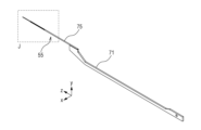
- FIG. 20A is a schematic perspective view showing the configuration of the buckling prevention portion 55.
- FIG. FIG. 20B is an enlarged view of the dashed line region J showing the configuration of the buckling prevention portion 55, showing an enlarged view of part of the inside of the buckling prevention portion 55.
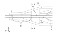
- FIG. 21A is a cross-sectional view of the curved body manipulator 50, an enlarged cross-sectional view of the broken line area G in FIG. 13, and FIG. 21B is an enlarged view of the broken line area K.
- FIG. 22A and 22B are cross-sectional views of the curved body manipulator 50.
- the curved body manipulator 50 is cut along the MM cross section, and the buckling prevention portion 55 extends from the negative direction of the z-axis toward the positive direction.
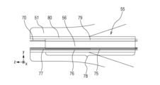
- 22B is an enlarged view of the dashed line area N.
- the buckling prevention portion 55 has an inner member 79 , an outer member 80 , nine hollow members 75 and elastic members 76 .
- the nine hollow members 75 and the elastic members 76 respectively correspond to the nine linear members 77 .
- FIGS. 20A and 20B The relative positional relationship of the hollow member 75, the elastic member 76, and the connecting member 71 with respect to the linear member 77 will be described with reference to FIGS. 20A and 20B, taking the drive shaft 1a as an example.
- a coil spring-like elastic member 76 is wound around a partial region of a linear member 77 extending from the inside of the hollow member 75 in the z-axis positive direction.
- a buckling prevention region 78 is formed by the hollow member 75 and the elastic member 76 .
- the outer diameter of the elastic member 76 is equal to or smaller than the outer diameter of the hollow member 75, and preferably larger than the holes 70a to 70i of the tubular member 70.
- the inner diameter of the elastic member 76 is preferably equal to or larger than the outer diameter of the linear member 77 .
- the elastic member 76 is arranged between the hollow member 75 and the tubular member 70 .
- Elastic member 76 is preferably a compression coil spring.
- the natural length of the elastic member 76 is such that the end of the elastic member 76 in the positive direction of the z-axis touches the end of the tubular member 70 of the bending body 210 when the bending portion 53 is linear along the z-axis direction.
- the negative direction end of the z-axis is preferably set to contact the end of the hollow member 75 .
- FIG. 23A shows a schematic perspective view of the inner member 79
- FIG. 23B shows a schematic front view of the inner member 79.
- the inner member 79 has a hollow shape with a through hole 79a inside, and nine U-shaped grooves 79b are provided around the through hole 79a.
- the buckling prevention region 78 is movable in the z-axis direction inside the groove 79b.
- a cylindrical outer member 80 is provided outside the buckling prevention region 78 to suppress radial displacement of the buckling prevention region 78 .
- the inner member 79 is arranged so as to be in contact with the tubular member 70, and arranged so that the inner skin 56 extends from the inside of the tubular member 70 in the z-axis negative direction. Furthermore, a part of the tubular member 70 is fitted in the outer member 80 , and the cylindrical inner wall of the outer member 51 holds the side surface of the outer member 80 , so that the buckling prevention portion 55 is supported by the outer member 51 . .
- the elastic member 76 fills the gap between the linear member 77 and the groove 79b in the radial direction. Further, by covering the linear member 77 with the elastic member 76, it is possible to suppress buckling even when the linear member 77 receives a load in the compression direction. Even if the linear member 77 were to buckle, the effect of minimizing deflection due to buckling can be expected.
- the intermediate portions 77b of the linear members 77 are linear.
- the curved body manipulator 50 according to the present embodiment can insert various tools toward the curved portion 53 as in the first embodiment.
- the insertion port 57a has a hollow shape with a through hole 57b.
- a bent pipe 58 is attached to the through hole 57b.
- a straight pipe 59 is inserted into the bent pipe 58 .
- a seal structure is formed between the curved pipe 58 and the straight pipe 59 by elastically deforming the curved pipe 58 by the straight pipe 59, and the internal airtightness is ensured.
- the bent tube 58 is made of a rubber tube or the like
- the straight tube 59 is made of a stainless steel pipe or the like.
- One end of the straight pipe 59 is fixed to the support portion 57e, and the other end is fitted inside the inner member 79 in a partial region in the z-axis direction as shown in FIG. 22B. Since the inner member 79 is elastically deformed by the straight pipe 59, a seal structure is formed between the inner member 79 and the straight pipe 59, and airtightness of the inside is ensured.
- the inner member 79 is placed in contact with the end surface of the tubular member 70, and the side surfaces of the tubular member 70 and the inner member 79 are covered with the outer member 80, whereby the tubular member 70 and the inner member 79 is effective in ensuring airtightness.
- a highly airtight hollow path can be secured from the curved tube 58 provided in the insertion port 57a to the inner skin 56 through the straight tube 59.
- a small camera, forceps, a biopsy tool, etc. as in the first embodiment, it is possible to observe and treat an object near the tip of the bending portion 53 .
- an irrigation suction tube is inserted, and liquid is ejected or sucked from the tip of the bending portion 53 through the irrigation suction tube, thereby cleaning an object near the tip of the bending portion 53 and administering a medicine. It is possible.
- the present embodiment similarly to the first embodiment, it is possible to efficiently transmit thrust to the linear member 77 arranged in a narrow space.
- ⁇ 73b can be placed on a circle with a radius much larger than radius r.
- the connecting members 72 and 73 adjacent in the circumferential direction around the central axis CA have bent portions 72f and 73f.
- a path for inserting and removing tools can be secured between the connection members 72 and 73, and a space for installing the insertion port 57a can be secured.
- an elastic member 76 that covers the linear member 77 is arranged between the joints 71 a to 73 a and the tubular member 70 of the bending body 210 in order to suppress the buckling of the linear member 77 .
- the natural length of the elastic member 76 has been set so that the elastic member 76 is compressed when the connecting members 71 to 73 are at the farthest position from the bending body 210 in the z-axis direction, but this is not the only option. not.
- the natural length of the elastic member 76 is set so that the length of the elastic member 76 is the same as the natural length when the connecting members 71 to 73 are located away from the bending body 210 in the z-axis direction. good too.
- a gap may be formed between the elastic member 76 and the hollow member 75 or between the elastic member 76 and the tubular member 70 of the bending body 210 .
- the elastic modulus of the elastic member 76 sufficiently low so that the restoring force of the elastic member 76 does not displace the drive shafts 1a to 1c, 2a to 2c, and 3a to 3c.
- a frictional force between the connecting members 71-73 and the groove 57c may be utilized. The frictional force can be adjusted by adjusting the size of the gap between the connecting members 71 to 73 and the groove 57c, the combination of the materials of the two, and the like.
- the drive shafts 1a to 1c, 2a to 2c, and 3a to 3c are transitioned from being pulled in the negative direction of the z-axis to being pushed in the positive direction. Even in this case, the state in which the linear member 70 is covered with the elastic member 76 is maintained. Therefore, it is possible to prevent the linear member 77 from buckling.
- the first section 61 is capable of two-degree-of-freedom motion of bending and turning in response to three-degree-of-freedom input using the three drive shafts 1a to 1c.
- the second section 62 is capable of two-degree-of-freedom motion of bending and turning in response to three-degree-of-freedom input using three drive shafts 2a-2c, and three drive-shafts 3a-3c are used.
- the third section 63 can move in two degrees of freedom of bending and turning in response to input of three degrees of freedom.
- the curved body manipulator 50 according to the present embodiment is configured to be capable of motion with six degrees of freedom in response to input with nine degrees of freedom.
- the inner skin 56 and the outer skin 52 are made of a stretchable material, and the drive shafts 1a to 1c, 2a to 2c, and 3a to 3c are pushed and pulled in the same direction.
- Each section 1-3 may be stretchable in the z-axis direction.
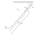
- FIG. FIG. 24 is a schematic perspective view of a curved body robot (continuous body robot) 101 in which a curved body manipulator (continuous body manipulator) 100 is incorporated.
- the curved body manipulator 100 includes a driven curved part 104 that extends in the longitudinal direction (z-axis direction) the driven curved part 54 of the curved body manipulator 50 described in the second embodiment, and a curved part 53 adjacent to the driven curved part 104. .
- the curved body manipulator 100 of the present embodiment differs from the curved body manipulator 50 of the second embodiment in the length of the driven bending portion 54 and the driven bending portion 104 . Further, the linear member in this embodiment differs in length from the linear member 77 in the second embodiment.
- a tubular member having the same cross-sectional shape as the tubular member 70 in the second embodiment and being longer than the tubular member 70 can be used.
- the tubular member may be a single component, or a single tubular member may be formed by joining a plurality of tubular members with different bending stiffnesses. At this time, it is preferable to select the material so that the bending rigidity decreases from the central member 57 toward the curved portion 53 .
- the ratio between the bending portion 53 and the driven bending portion 104 in the present embodiment is different from the ratio between the bending portion 53 and the driven bending portion 54 of the bending body manipulator 50 in the second embodiment.
- Section 104 is longer.
- the total length of the driven bending portion 104 is approximately 500 mm while the total length of the bending portion 53 is approximately 60 mm.
- the driven bending portion 104 is preferably made of a flexible thermoplastic elastomer or the like.
- the curved body robot 101 is provided with a curved body manipulator 100 and an actuator unit (driving unit) 90 having a drive source for pushing and pulling the drive shafts 1a to 1c, 2a to 2c, and 3a to 3c.
- the curved body manipulator 100 is detachably attached to the actuator unit 90 .
- the actuator unit 90 has a plurality of driving devices 901a, 901b, 901c, 902a, 902b, 902c, 903a, 903b, 903c.
- Drives 901 a , 901 b , 901 c are detachably connected to force receiving portions 71 b of drive shafts 1 a - 1 c and configured to move connecting member 71 .
- the drive devices 902a and 902c are detachably connected to the force receiving portions 71b of the drive shafts 2a and 2c, respectively, and configured to move the connecting member 71.
- the drive 902b is detachably connected to the force receiving portion 73b of the drive shaft 2b and configured to move the connecting member 73. As shown in FIG.
- the drive devices 903a and 903c are detachably connected to the force receiving portions 71b of the drive shafts 3a and 3c, respectively, and configured to move the connecting member 71.
- the drive 903b is detachably connected to the force receiving portion 72b of the drive shaft 3b and configured to move the connecting member 72. As shown in FIG.
- the actuator unit 90 is formed by radially arranging the driving devices 901a, 901b, 901c, 902a, 902b, 902c, 903a, 903b, and 903c around the central axis CA.
- FIG. 25 is a diagram illustrating a drive device 901a for driving the drive shaft 1a.
- the drive device 901a Since the drive devices 901a, 901b, 901c, 902a, 902b, 902c, 903a, 903b, and 903c have the same configuration, the drive device 901a will be described as a representative.
- the driving device 901a has an electromagnetic motor 91.
- the electromagnetic motor 91 is connected via a coupling 92 to a conversion section 94 supported by two sets of bearings 93 to rotate the conversion section 94 .
- the conversion unit 94 converts rotational motion about the z-axis into linear motion in the z-axis direction.
- a ball screw or a lead screw can be used as the conversion portion 94 .
- a spiral groove is formed in the conversion portion 94 and engages with the tractor 97 .
- the driving device 901 has a linear guide 95 including a rail 95 a fixed to the housing 96 and a slider 95 b capable of moving on the rail 95 .
- a tractor 97 is connected to the linear guide 95 via a slider 95b and is movable in the z-axis direction.
- the upper end of the tractor 97 is engaged with the force receiving portion 71b of the connecting member 71 by a pin 98. As shown in FIG. With the above configuration, it is possible to push and pull the connection member 71 in the z-axis direction by rotating the electromagnetic motor 91 .
- the attitude of the bending portion 53 can be easily set by the actuator unit 90 that drives the drive shafts 1a-1c, 2a-2c, and 3a-3c.
- the bending body manipulator 100 can be used as a bronchoscope, for example.
- the bending body manipulator 100 can be inserted through the mouth to selectively navigate bifurcations in the bronchi.
- irrigation using an irrigation suction tube, biopsy, minimally invasive ablation treatment, and the like can be performed in a target region deep in the lung.
- connection members 71 to 73 using a direct acting actuator can also be easily applied.
- each embodiment shown above can be appropriately combined as necessary.
- the curved body manipulator and curved body robot shown in each embodiment can be used as a medical device to be inserted into the patient's body.
Landscapes
- Engineering & Computer Science (AREA)
- Mechanical Engineering (AREA)
- Robotics (AREA)
- Physics & Mathematics (AREA)
- Health & Medical Sciences (AREA)
- Life Sciences & Earth Sciences (AREA)
- Surgery (AREA)
- Optics & Photonics (AREA)
- Heart & Thoracic Surgery (AREA)
- Public Health (AREA)
- Pathology (AREA)
- Biomedical Technology (AREA)
- Nuclear Medicine, Radiotherapy & Molecular Imaging (AREA)
- Medical Informatics (AREA)
- Molecular Biology (AREA)
- Animal Behavior & Ethology (AREA)
- General Health & Medical Sciences (AREA)
- Radiology & Medical Imaging (AREA)
- Veterinary Medicine (AREA)
- Biophysics (AREA)
- Rehabilitation Therapy (AREA)
- Astronomy & Astrophysics (AREA)
- General Physics & Mathematics (AREA)
- Manipulator (AREA)
- Instruments For Viewing The Inside Of Hollow Bodies (AREA)
- Endoscopes (AREA)
Abstract
湾曲体マニピュレータが、湾曲部を含む湾曲体と、ガイド部材と、湾曲部に接続された複数の入力部を有する。複数の入力部のそれぞれが(i)湾曲部に接続され、延伸方向に沿って延び、延伸方向に沿って移動された場合に湾曲部を湾曲させるように構成された線状部材と、(ii)線状部材が固定された固定部と、力受け部とを有し、移動方向に沿って移動可能であり、延伸方向に直交する方向について、力受け部が固定部よりも線状部材から遠い位置に配置された接続部材と、を有する。力受け部が力を受けた場合に、線状部材を延伸方向に沿って移動するように、接続部材はガイド部材によってガイドされて移動方向に沿って移動される。固定部は、湾曲体と固定部の間で線状部材が直線状に延びるように配置される。
Description
本発明は、線状部材によって湾曲される湾曲部を有する湾曲体マニピュレータ、および湾曲マニピュレータを有する湾曲体ロボットに関する。
医療用内視鏡や工業用内視鏡などの分野において、細長く伸びた湾曲体マニピュレータの先端付近に湾曲部が設けられ、ワイヤなどの線状部材を押し引きすることによって、湾曲部の湾曲を操作できるものがある。
米国特許出願公開第2021/0121051号明細書は、湾曲体がワイヤによって湾曲される構成を開示する。具体的には、ワイヤの一端が湾曲体に接続され、他端が駆動ロッドに接続されている。そして、駆動ロッドに力が付与され、駆動ロッドがワイヤを移動することによって湾曲体が湾曲される。駆動ロッドは湾曲体の中心からオフセットした位置に配置されており、ワイヤは円筒体の溝に沿って湾曲体と駆動ロッドの間で屈曲され、駆動ロッドに接続されている。
線状部材に接続された接続部材が力を受けることで線状部材が移動し、湾曲部が湾曲される構成において、接続部材と湾曲体との間で線状部材が屈曲していると、接続部材の移動による湾曲部の湾曲操作に対し、線状部材の屈曲が影響を及ぼす場合がある。例えば、線状部材を押す場合と引く場合とで、線状部材の軌跡や、線状部材と線状部材を案内する部材との間に生じる摩擦力が異なる。その結果、線状部材を押す場合と引く場合とで、接続部材の動きと湾曲部の動きの関係が異なる場合がある。
本発明の目的の一つは、接続部材と湾曲体との間における線状部材の屈曲を抑制することである。
本出願に係る発明の一つは、以下のようなものである。
湾曲部を含む湾曲体と、
ガイド部材と、
前記湾曲部に接続された複数の入力部であって、それぞれが(i)前記湾曲部に接続され、延伸方向に沿って延び、前記延伸方向に沿って移動された場合に前記湾曲部を湾曲させるように構成された線状部材と、(ii)前記線状部材が固定された固定部と、力受け部とを有し、移動方向に沿って移動可能であり、前記延伸方向に直交する方向について、前記力受け部が前記固定部よりも前記線状部材から遠い位置に配置された接続部材と、を有する複数の入力部と、
を有し、
前記力受け部が力を受けた場合に、前記線状部材を前記延伸方向に沿って移動するように、前記接続部材は前記ガイド部材によってガイドされて前記移動方向に沿って移動され、
前記固定部は、前記湾曲体と前記固定部の間で前記線状部材が直線状に延びるように配置されることを特徴とする湾曲体マニピュレータ。
ガイド部材と、
前記湾曲部に接続された複数の入力部であって、それぞれが(i)前記湾曲部に接続され、延伸方向に沿って延び、前記延伸方向に沿って移動された場合に前記湾曲部を湾曲させるように構成された線状部材と、(ii)前記線状部材が固定された固定部と、力受け部とを有し、移動方向に沿って移動可能であり、前記延伸方向に直交する方向について、前記力受け部が前記固定部よりも前記線状部材から遠い位置に配置された接続部材と、を有する複数の入力部と、
を有し、
前記力受け部が力を受けた場合に、前記線状部材を前記延伸方向に沿って移動するように、前記接続部材は前記ガイド部材によってガイドされて前記移動方向に沿って移動され、
前記固定部は、前記湾曲体と前記固定部の間で前記線状部材が直線状に延びるように配置されることを特徴とする湾曲体マニピュレータ。
本出願に係る発明の一つは、以下のようなものである。
湾曲部を含み、複数の孔を有する湾曲体と、
ガイド部材と、
前記湾曲部に接続された複数の入力部であって、それぞれが(i)前記湾曲部に接続され、延伸方向に沿って延び、前記延伸方向に沿って移動された場合に前記湾曲部を湾曲させるように構成された線状部材と、(ii)前記線状部材が固定された固定部と、力受け部とを有し、移動方向に沿って移動可能であり、前記延伸方向に直交する方向について、前記力受け部が前記固定部よりも前記線状部材から遠い位置に配置された接続部材と、を有する複数の入力部と、
を有し、
前記線状部材は前記複数の孔の一つに挿入され、かつ前記固定部に固定される被固定部を有し、
前記力受け部が力を受けた場合に、前記線状部材を前記延伸方向に沿って移動するように、前記接続部材は前記ガイド部材によってガイドされて前記移動方向に沿って移動され、
前記移動方向に沿って見たとき、前記被固定部と前記複数の孔の一つは、少なくとも部分的に重なることを特徴とする湾曲体マニピュレータ。
ガイド部材と、
前記湾曲部に接続された複数の入力部であって、それぞれが(i)前記湾曲部に接続され、延伸方向に沿って延び、前記延伸方向に沿って移動された場合に前記湾曲部を湾曲させるように構成された線状部材と、(ii)前記線状部材が固定された固定部と、力受け部とを有し、移動方向に沿って移動可能であり、前記延伸方向に直交する方向について、前記力受け部が前記固定部よりも前記線状部材から遠い位置に配置された接続部材と、を有する複数の入力部と、
を有し、
前記線状部材は前記複数の孔の一つに挿入され、かつ前記固定部に固定される被固定部を有し、
前記力受け部が力を受けた場合に、前記線状部材を前記延伸方向に沿って移動するように、前記接続部材は前記ガイド部材によってガイドされて前記移動方向に沿って移動され、
前記移動方向に沿って見たとき、前記被固定部と前記複数の孔の一つは、少なくとも部分的に重なることを特徴とする湾曲体マニピュレータ。
本発明は、接続部材と湾曲体との間における線状部材の屈曲を抑制することができる。
以下、本発明の実施形態について、添付図面を参照して詳細に説明する。なお、実施例中における各座標軸は共通のものである。また、本発明は、各実施例の構成のみに限定されず、各実施例の組み合わせから導かれる実施の形態についても包含するものである。
[実施例1]
図1A、図1B乃至図10を用いて実施例1について説明する。
図1A、図1B乃至図10を用いて実施例1について説明する。
<湾曲体マニピュレータの構造>
湾曲体マニピュレータ10の構造について説明する。図1A、図1Bは、湾曲体マニピュレータ10の概略斜視図である。図1Bでは、湾曲体マニピュレータ10の外皮12が非表示とされている。図2Aは湾曲体マニピュレータ10の正面図であり、後述する湾曲体110側から湾曲体マニピュレータ10を見た図である。図2Bは湾曲体マニピュレータ10の背面図であり、図2Aとは反対側から湾曲体マニピュレータ10を見た図である。
湾曲体マニピュレータ10の構造について説明する。図1A、図1Bは、湾曲体マニピュレータ10の概略斜視図である。図1Bでは、湾曲体マニピュレータ10の外皮12が非表示とされている。図2Aは湾曲体マニピュレータ10の正面図であり、後述する湾曲体110側から湾曲体マニピュレータ10を見た図である。図2Bは湾曲体マニピュレータ10の背面図であり、図2Aとは反対側から湾曲体マニピュレータ10を見た図である。
湾曲体マニピュレータ10は、湾曲部13を含む湾曲体110と、湾曲体110が取り付けられるフレームとしての外装部材11、湾曲体110の湾曲部13に接続された入力部としての駆動軸16(16a、16b、16c)を有する。本実施例に係る湾曲体マニピュレータ10は、複数の入力部として、3つの駆動軸16(16a、16b、16c)を有する。
なお、湾曲体は連続体とも呼ぶことができ、湾曲マニピュレータは連続体マニピュレータと呼ぶこともできる。
湾曲部13は、先端部材14と複数のガイドリング15を含み、先端部材14と複数のガイドリング15は外皮12によって覆われている。外装部材11の内部には、中心部材23が収容されている。湾曲体マニピュレータ10は、湾曲部13の先端から中心部材23の後端までz軸方向に貫く貫通孔18が形成された中空構造を有する。
3つの駆動軸16a~16cは、互いに独立して駆動されることができ、手動または、アクチュエータによってz軸方向にスライドされることにより、湾曲部13が湾曲される。言い換えれば、湾曲部13の湾曲は、それぞれがz軸方向の自由度を有する各駆動軸16a~16cの移動によって制御される。
ここで、湾曲体110において、外装部材10に支持される端部を後端と呼ぶ。湾曲体110は、後端とは反対側の先端から対象物に挿入される。湾曲体110において、先端を遠位端と呼び、後端を近位端と呼ぶことができる。
次に、図3A~図3Cを用いて、湾曲体マニピュレータ10の構造について、さらに詳しく説明する。
図3Aは、湾曲体マニピュレータ10の中心を通り、y-z平面に平行な断面で切断した概略断面図である。図3Bは、図3Aの破線領域Aの拡大図、図3Cは図3Aの破線領域Bの拡大図である。
湾曲部13は、先端部材14及び、所定の間隔で配列された複数のガイドリング15(本実施例では9個)を有する。湾曲部13の先端には先端部材14が配置されている。湾曲体110は、ガイドリング15と同一の断面形状を有する管状部材(長手部材)22を有する。管状部材22は、ガイドリング15と所定の間隔をあけて、湾曲部13に対して後端(近位端)側に配置されている。管状部材22は外装部材11の内部に挿入されて、外装部材11によって支持されており、外装部材11に対して固定される。
ここで、湾曲体110は、貫通孔18が形成された円柱形状である。言い換えれば、湾曲体110は円筒形状である。湾曲体110の中心軸を、中心軸CAとする。湾曲体110が直線状になったとき、中心軸CAは、湾曲体マニピュレータ10の中心軸と一致する。
複数の駆動軸(16a~16c)は、中心軸CAを囲むように、円周上に配置されている。駆動軸16a~16cのそれぞれは、湾曲部13の先端部材14に接続された可撓性を有する線状部材20と、線状部材20に接続された接続部材21を有する。接続部材21は、線状部材20と比較して変形しにくい部材ということができる。つまり、同じ力が作用した際の変形は、線状部材20よりも接続部材21のほうが小さい。本実施例において、駆動軸16a~16cは同一構成であるため、代表して駆動軸16aについて説明する。
接続部材(中間部材)21は接合部(固定部)21aと、力受け部21bを有する。後述するように、接合部21aには、線状部材20が分離不能に固定されている。接続部材21は、z軸方向に沿って移動可能に構成されている。力受け部21bは湾曲体マニピュレータ10の外側(外装部材11の外側)に露出されている。力受け部21bが力(より具体的には、湾曲体マニピュレータ10の外側から伝達される外力)を受けることで、接続部材21はz軸方向に沿って移動される。使用者は、手動またはモータ等の駆動源を用いて力受け部21bに力を付与することができる。接合部21aに固定される線状部材20の一部を、被接合部(被接続部、被固定部)20aと呼ぶことができる。
本実施形態において、接続部材21は、接合部21a、力受け部21bおよび接合部21aと力受け部21bを連結する連結部分を一体的に有しているが、複数の部品を組み合わせて、接続部材21を構成してもよい。
線状部材20が延びる方向を、延伸方向と呼ぶ。線状部材20の延伸方向は、湾曲体110の長手方向と一致する。図3A、図3Bに示した状態(湾曲体110が直線状の状態)では、線状部材20の延伸方向はz軸方向と一致する。
延伸方向に直交する方向(図3Aにおけるy軸方向)について、力受け部21bは、接合部21aよりも線状部材20から遠い位置に配置される。一方、湾曲体110の中心軸CAに直交する方向(図3Aにおけるy軸方向)について、接合部21aは力受け部21bよりも中心軸CAに近い位置に配置される。
接続部材21が移動方向としてのz軸方向に沿って移動することで、線状部材20が一体的に延伸方向に移動される。線状部材20が延伸方向に移動されることにより、湾曲部13が湾曲される。
上述したように、湾曲体マニピュレータ10は複数の駆動軸(16a~16c)を含んでいる。それぞれの駆動軸を、”第1”や”第2”などの番号によって区別することもできる。例えば、駆動軸16aを第1駆動軸(第1入力部)と呼ぶことができる。この場合、駆動軸16aの線状部材20を第1線状部材、接続部材21を第1接続部材と呼ぶことができる。また、第1線状部材の延伸方向を第1延伸方向、第1接続部材の移動方向を第1移動方向、第1接続部材の固定部を第1固定部、第1接続部材の力受け部を第1力受け部と呼ぶことができる。同様に、駆動軸16bを第2駆動軸(第2入力部)と呼び、駆動軸16cを第3駆動軸(第3入力部)と呼ぶことができる。
外装部材11の内部には、中心部材23が配置され、接続部材21は、中心部材23によってその側面をスライド可能に支持される。図4A~図4Cを用いて、中心部材23について説明する。図4Aは、中心部材23の概略正面図、図4Bは、中心部材23のE-E切断面における概略断面図、図4Cは、中心部材23の概略背面図である。
中心部材23には、半径方向に延びる幅Wの溝(ガイド溝)23a、23b、23cが120度おきに設けられ、中心には貫通孔23dが設けられる。なお、半径方向の中心は、湾曲体110の中心軸CAと一致する。貫通孔23dは、貫通孔18の一部を形成する。
溝23a、23b、23cには、それぞれの駆動軸16a~16cの接続部材21が嵌まり込む。溝23aは駆動軸23aに、溝23bは駆動軸23bに、溝23cは駆動軸23cに対応する。図4A~図4Cでは、溝23aがy軸方向に沿うように配置されている。溝23a、23b、23cは同一形状であるため、代表して溝23aについて説明する。
溝23aは図4Bに示すように、半径方向に深さD1を有する領域L3と、深さD2を有する領域L4を有し、D1>D2である。
後述するように、接続部材21は板形状を有する板部分を有し、溝幅Wに対して僅かに小さい板厚(厚み)を有する。
図3Cに示すように、接続部材21が力を受けておらず、湾曲体110が直線状の場合には、接続部材21の接合部21aが中立位置にある。この状態を中立状態と呼ぶ。
接合部21aは、中立位置からz軸正方向にL1、z軸負方向にL2移動可能である。また、半径方向について、外装部材(カバー部材)11が中心部材23の23a、23b、23cを外側から覆うように嵌まっていることにより、接続部材21の半径方向の移動が規制されている。これにより、接続部材21の周方向(厚み方向)、半径方向の運動が拘束される。一方、z軸方向の運動は、所定の範囲(L1+L2)に制限される。
つまり、中心部材23と外装部材11は、接続部材21をガイドするガイド部材としての機能を有する。したがって、中心部材23を第1ガイド部材と呼び、外装部材11を第2ガイド部材と呼ぶことができる。
力受け部21bが力を受けると、接続部材21は、中心部材23と外装部材11とにガイドされ、移動方向(本実施例ではz軸方向)に移動される。その結果、固定部21aに固定された線状部材20は延伸方向に移動し、湾曲部13が湾曲される。中心部材23と外装部材11によって、移動方向への接続部材21の移動が許容される一方で、移動方向と交差する方向(好ましくは直交する方向)への接続部材21の移動が規制される。これにより、接続部材21が移動方向に向けて正確に移動される。
具体的には、中心部材23は、中心軸CAの周りの円周方向について、接続部材21の移動を抑制する。中心部材23は、接続部材21が線状部材20の延伸方向と交差する方向に移動することを抑制し、線状部材22の曲げを抑制する。また、中心部材23は、接続部材21が線状部材20を中心に回転することを抑制し、線状部材20のねじれを抑制する。一方、外装部材11と中心部材23は、中心軸CAを中心とした半径方向について、接続部材21の移動を抑制する。外装部材11と中心部材23(溝23a、23b、23cの端部)は、接続部材21が線状部材20の延伸方向と交差する方向に移動することを抑制し、線状部材22の曲げ(屈曲)を抑制する。
その結果、接続部材21のスティックスリップが抑制され、接続部材21は、中心部材23に対して滑らかにスライド可能である。また、接続部材21が移動方向と交差する方向に移動することが抑制されるため、線状部材20が屈曲されることを抑制される。
図5A、図5Bを用いて、先端部材14とガイドリング15について説明する。本実施例では、先端部材14とガイドリング15は、同一形状を有する。図5Aは先端部材14とガイドリング15の概略正面図、図5Bは先端部材14とガイドリング15概略側面図である。
先端部材14及び、ガイドリング15は、貫通孔15dを有する円環状の形状を有し、その中心から同一半径rの位置に3つの孔15a、15b、15cを有する。3つの孔15a、15b、15cのそれぞれには、駆動軸16a~16cのそれぞれの線状部材20が挿入される。本実施例では、3つの孔15a~15cは、半径rの円を等分するように等間隔に配置され、図の角度α1=α2=120度である。貫通孔15dは、貫通孔18の一部を形成する。
図6A、図6Bを用いて、湾曲体110の管状部材22について説明する。図6Aは、管状部材22の概略正面図、図6Bは、管状部材22の概略側面図である。図6Aにおいては、接続部材21、線状部材20が点線で示されている。
先端部材14及び、ガイドリング15と同様に、管状部材22は貫通孔22dを有する円環状の形状を有する。管状部材22は、可撓性を有し、その中心から同一半径rの位置に3つの孔22a、22b、22cを有する。孔22a~22cのそれぞれには、駆動軸16a~16cのそれぞれの線状部材20が挿入される。貫通孔22dは、貫通孔18の一部を形成する。また、管状部材22は、湾曲体110の近位端に配置されており、孔22a~22cも、湾曲体110の近位端に配置されているということができる。
線状部材20の他端(近位端側の端部)は、接続部材21の接合部21aにおいて接続部材21に接合される。ここで、駆動軸16aの線状部材20は、先端部材14、ガイドリング15、管状部材22それぞれの孔14a、15a、22aの中を通過するように配置される。駆動軸16bの線状部材20は、先端部材14、ガイドリング15、管状部材22それぞれの孔14b、15b、22bの中を通過するように配置される。駆動軸16cの線状部材20は、先端部材14、ガイドリング15、管状部材22それぞれの孔14c、15c、22cの中を通過するように配置される。
図3Bに示すように、湾曲体110は、チューブ状の内皮19と、チューブ状の外皮12を有する。内皮19と外皮12は可撓性を有する。
先端部材14及び、ガイドリング15は、内皮19と外皮12の間に配置されている。先端部材14及び、ガイドリング15の貫通孔15dの内壁面が、内皮19の外周面(外側面)に接合される。一方、先端部材14及び、ガイドリング15の外周面(外側面)には、外皮12が配置される。
駆動軸16a~16cのそれぞれの線状部材20は、先端部材14の孔15a~15cに一端(遠位端側の端部)が固定され、ガイドリング15の孔15a~15cを通り、ガイドリング15の孔に対し摺動可能となるように配置される。線状部材20はz軸の負方向(近位側)に向かって管状部材22の孔22a~22cの中を通り、外装部材11の内部に至る。外装部材11の内部には、接続部材21が配置される。
図7A~図7Bを用いて、接続部材21について説明する。図7Aは接続部材21の概略正面図、図7Bは接続部材21の概略側面図である。
図7A、図7Bに示すように、接続部材21は板形状(シート形状)を有する板部分(シート部分)21cを有している。本実施例においては、接続部材21の全体が板形状を有する板部分21cであるということができるが、板部分21cは接続部材21の一部でもよい。
ここで、板形状とは、互いに直交する厚み方向、幅方向、長さ方向について、幅方向の長さ(幅、第2長さ、第1面方向)が厚み方向の長さ(厚み、第1長さ)よりも長く、長さ方向の長さ(第3長さ、第2面方向)が幅方向の長さ以上あることをいう。つまり、接続部材21の板状の部分(本実施例では接続部材21の全体)の厚みとは、互いに直交する3つの方向における長さのうち、一番短い長さを言う。また、厚み方向に直交する方向を面方向と呼ぶことができる。図7A、図7Bにおいて、接続部材21の板部分21cの厚み方向はx軸方向、幅方向はy軸方向、長さ方向はz軸方向である。
接続部材21は、厚み方向に直交する面(面方向に広がる面)21c1を有する。接続部材21の移動方向はz軸方向であり、接続部材21は、面21c1が移動方向に沿うように配置されている。中心部材23は溝23において一対の面21c1と当接して、接続部材21をガイドする。このように、中心部材23が面21c1をガイドすることにより、接続部材21は移動方向に安定して移動できる。
本実施例において、接続部材21はL字形状を有している。前述したように、接続部材21は、接合部21aと、力受け部21bを有している。接続部材21の移動方向(z軸方向)において、力受け部21bは、接合部21aから離れた位置(接合部21aに対してずれた位置)に配置されている。
一方、接続部材21は、線状部材20の近傍に板部分21cが配置されている。接合部21aは、板部分21cの端部に配置されている。駆動軸16a~16cにおいて、接続部材21は、面21c1が中心軸CAの周りの周方向を向くように配置されており、面21c1が、中心軸CAから放射線状に配置される。このように駆動軸16a~16cを配置することで、接合部21aを中心軸CAの近くに配置することができる。
接合部21aを中心軸CAの近くに配置すると、駆動軸16a~16cの接続部材21同士の距離が近くなるが、接続部材21が板部分21cを有していることにより、接続部材21同士を小さいスペースの中で近接させて配置できる。また、接合部21aが配置される板部分21cの端部は、平板形状を有している。したがって、接続部材21同士をさらに小さいスペースの中で近接させて配置できる。
図3Aに示すように、接合部21aは、湾曲体110と接合部21aの間において、線状部材20が直線状に延びるように配置されている。湾曲体110と接合部21aの間に位置する線状部材20の一部を、中間部分20bと呼ぶことができる。このとき、線状部材20が完全な直線であるときを基準(0°)として、線状部材20の中間部分20bの屈曲角度は、10°以内が好ましく、5°以内がより好ましい。
一方、図6Aは、接続部材21の移動方向に沿って見た図、または湾曲体110が直線になった状態で中心軸CAもしくは線状部材20の延伸方向に沿って見た図ということができる。上述のように、駆動軸16a~16cのそれぞれの線状部材20は、湾曲体110の管状部材22の複数の孔(22a~22c)の一つに挿入される。例えば駆動軸16aについて、線状部材20は、湾曲体110の管状部材22の複数の孔(22a~22c)の一つである孔22aに挿入される。図6Aに示すように、孔22aと駆動軸16aの接合部21a、孔22aと駆動軸16aの被固定部20aとは、少なくとも部分的に重なる。孔22bと駆動軸16b、孔22cと駆動軸16cの関係も同様である。
湾曲体110と接合部21aの間において線状部材20が屈曲されていると、接続部材21が接合部21aを介して線状部材20を移動方向に移動させた際、線状部材20の一部(中間部分20b)が線状部材20の延伸方向と交差する方向にも移動する。また、接続部材21が線状部材20を押すときと、引っ張るときとで、線状部材20の軌跡や、線状部材20を案内する部材との間の摩擦力が異なる。
一方、接合部21aから湾曲体110にわたって、線状部材20が直線状に延びていることにより、線状部材20の屈曲が抑制され、接続部材21が移動方向に移動した際に、線状部材20が延伸方向とは交差する方向に移動することが抑制される。また、接続部材21が線状部材20を押すときと、引っ張るときとで、線状部材20の軌跡や、線状部材20を案内する部材との間の摩擦力に差異が生じることも抑制される。
湾曲部13は、線状部材20が延伸方向に移動することによって湾曲されるため、接合部21aから湾曲体110に向けて、直線的に線状部材20を移動させることによって、湾曲部13を効率的に、かつ精度よく湾曲させることができる。
次に、線状部材20と接続部材21の接合方法について、図8A~図8Dを用いて説明する。図8Aは、線状部材20が接続部材21に接合された状態の概略正面図、図8Bは、線状部材20が接続部材21に接合された状態の概略側面図、図8Cは破線領域Fの拡大図、図8Dは破線領域Fの拡大図である。なお、図8Dに示される構成は、図8Cに示される構成の変形例である。
線状部材20の被固定部20aは接続部材21の接合部(連結部、固定部)21aに接合される。線状部材20と接続部材21が接する箇所のみを接合することも可能であるが、図8Cに示すように、接合材24によって、両者をより強固に接合することができる。
線状部材20としては、ピアノ線、ステンレス系バネ線材、ニッケルチタン合金の線材などで形成されたワイヤを用いることができる。接続部材21は、鉄、ステンレス、銅、アルミニウム合金などの金属、ポリカーボネートやPEEK(ポリエーテルエーテルケトン)、ABSなどの樹脂やアルミナやジルコニアなどのセラミックスで形成することができる。接合材24としては、エポキシ系の接着剤や紫外線硬化樹脂などを用いることができる。接続部材21を金属で形成した場合には、線状部材20と接続部材21は溶接や、ろう付けによって接合することができ、この場合、接合材24は溶接金属や、ろう材を用いることができる。
また、接続部材21と線状部材20は、図8Dのように接合することも可能である。接続部材21の接合部21aに対し、接合部21aをz軸方向に貫く貫通孔21cを設け、貫通孔21cの中に線状部材20を挿入することにより両者を接合することが可能である。線状部材20を挿入した後、嫌気性接着剤や瞬間接着剤を用いて線状部材20を固定してもよいし、接合部21aを変形させることで線状部材20を固定してもよい。
以上の構成によると、接続部材21の末端に設けられた力受け部21bにアクチュエータや手動で動かすハンドルを取り付けることで、駆動軸16a~16cを互いに対して独立にz軸方向に押し引きすることができる。
<湾曲動作>
次に、駆動軸16a~16cを駆動することにより湾曲体マニピュレータ10の湾曲部13を曲げる湾曲動作について、図9、図10を用いて説明する。図9は、湾曲部13が曲がった状態の湾曲体マニピュレータ10の概略斜視図である。図10は、湾曲部13が曲がった状態の湾曲体マニピュレータ10の概略断面図である。図10は、湾曲体マニピュレータ10の中心を通る断面図である。
次に、駆動軸16a~16cを駆動することにより湾曲体マニピュレータ10の湾曲部13を曲げる湾曲動作について、図9、図10を用いて説明する。図9は、湾曲部13が曲がった状態の湾曲体マニピュレータ10の概略斜視図である。図10は、湾曲部13が曲がった状態の湾曲体マニピュレータ10の概略断面図である。図10は、湾曲体マニピュレータ10の中心を通る断面図である。
駆動軸16a~16cを適切に押し引きすることで、湾曲部13の曲率を一定に保ちながらy-z平面内で湾曲部13を曲げることができる。湾曲部13が水平状態(直線状態)であるときの、z軸方向における各駆動軸16a~16cの端部の位置をZoとし、各駆動軸16a~16cのz軸方向変位を各々Za~Zcとする。図10に示した状態では、駆動軸16aをz軸負方向にZa引き、駆動軸16b、16cをz軸正方向にZb、Zc押すことで湾曲動作を実現している。
ここで、湾曲部13の中心を通る曲率半径をR、この部分の弧長をSとすると、次式が得られる。
S=Rθ (式1)
S=Rθ (式1)
駆動軸16a、16b、16cのそれぞれに対応する位置での湾曲部13の曲率半径を各々Ra、Rb、Rcとすると、図5Aで示した幾何学的な関係に基づき、次式が得られる。
Ra=R-r (式2)
Rb=R+r/2 (式3)
Rc=R+r/2 (式4)
Ra=R-r (式2)
Rb=R+r/2 (式3)
Rc=R+r/2 (式4)
駆動軸16a、16b、16cの湾曲部13の弧長と、各駆動軸6a、16b、16cの変位の関係に基づいて、次式が得られる。
Raθ=S-Za (式5)
Rbθ=S+Zb (式6)
Rcθ=S+Zc (式7)
Raθ=S-Za (式5)
Rbθ=S+Zb (式6)
Rcθ=S+Zc (式7)
(式1)~(式4)を(式5)~(式7)へ代入することで、各駆動軸の変位が次のように算出される。
Za=rθ (式8)
Zb=rθ/2 (式9)
Zc=rθ/2 (式10)
Za=rθ (式8)
Zb=rθ/2 (式9)
Zc=rθ/2 (式10)
(式8)~(式10)より、湾曲部13をy-z平面内で湾曲させる際の各駆動軸16a、16b、16cの変位の関係は次式で表すことができる。
Za=2Zb=2Zc (式11)
Za=2Zb=2Zc (式11)
同様に、駆動軸16a、16b、16cのz軸方向変位を適切に設定することで、Z軸を含む任意の平面で湾曲部13を湾曲することが可能である。すなわち、湾曲部13の曲率半径Rを維持した状態で、z軸周りに旋回動作を行うことができる。従って、本実施例の湾曲体マニピュレータ10の湾曲部13は湾曲と旋回の2つの自由度を持つということができる。
以上、湾曲部13に半径rで配置されている線状部材20に対し、接続部材21から効率よく推力を伝達することが可能である。湾曲部13を湾曲させるために線状部材20を押し引きする際、線状部材20は管状部材22から接続部材21に接合される箇所(接合部21a)に至るまで直線状に配置される。そのため、線状部材20を押す場合と引く場合の経路が同じとなるため、線状部材20を押す場合の動的な特性と、線状部材20を引く場合の動的な特性とに差が生じにくくなる。
また、接続部材21を板状としているため、機械加工、射出成型、ダイカスト、プレス加工、平面研削等で容易に製造することができ、接続部材21が高精度でスムースにスライド移動することができる。従って、線状部材20を押すときと引くときの制御性能のばらつきを低減させることが可能である。
加えて、本実施例の構成によれば、狭小空間に配置された線状部材20に対して容易に推力を伝達することが可能である。例えば、湾曲体マニピュレータ10を医療用の経鼻内視鏡として用いる場合、外皮12の直径が約5mm、内皮19の直径が約3mm、線状部材20が配置される半径rについて、r=約2mmとなることが想定される。このような狭小空間に配置される複数の線状部材20に対し、独立に推力を伝達するのは容易ではない。しかし、中心部材23に案内される接続部材21を用いて推力を伝達することで、力を伝達するための力受け部21bを線状部材20が配置される半径rよりも十分大きな半径を有する円上に配置することができる。
従って、モータ等のアクチュエータやハンドルを用いて各駆動軸16a~16cに推力を伝達する際に、モータ等のアクチュエータやハンドルの配置や大きさに関する設計の自由度が向上し、狭小空間への力の伝達が容易になる。
なお、本実施例に係る湾曲体マニピュレータ10は、貫通孔18を利用して中心部材23側から湾曲部13に向かって様々なツールを挿入することが可能である。
例えば、貫通孔18に小型カメラを挿入することで、湾曲体110が挿入される対象の内部の観察を行うことができる。一方、力受け部21bにモータ等のアクチュエータを接続した状態で小型カメラを挿入する場合、カメラの外装が線状部材20と接触して、カメラの信号線がアクチュエータのグランドとショートすると、ノイズが発生する等の現象が生じる場合がある。
そこで、本実施例における接続部材21の材質を非導電材料で形成する、または、導電材料で形成しても表面を非導電性の材料で塗装またはコーティングすることにより、線状部材20とアクチュエータとの間を電気的に絶縁することが可能である。例えば、接続部材21をアルミ合金で形成する場合、力受け部21b近傍にアルマイト処理を施すことで、絶縁が可能である。
また、湾曲体マニピュレータ110を医療装置に用いる場合、カメラの他に、鉗子や生検ツールなどを貫通孔18に挿入して、体内の狭小空間において医療的な処置を行うことができる。
上述のように、本実施形態においては、線状部材20を直線状に配置しているため、線状部材20が座屈するリスクを低減し、線状部材20の駆動に伴う摩擦力を低減または安定させることができる。接続部材20の厚みと中心部材23の溝(23a~23c)の幅Wの寸法を適切に設定し、接続部材20と溝(23a~23c)の間の隙間を適切な大きさとすることで、摩擦力が適切に設定される。
また、中心部材23と接続部材21の材料を適切に選択することにより、溝23a、23b、23cと接続部材21との間に出来る隙間を小さく設定しても、溝23a、23b、23cの内部を接続部材21が滑らかに摺動することができる。例えば、線状部材20と接続部材21とを溶接で接合するために接続部材21にステンレスなどの金属材料を選択する場合、中心部材23を摺動性の高いポリアセタールなどの樹脂材料で形成することが好ましい。その結果、最大静止摩擦力と動摩擦力の大きさが近くなり、接続部材21が中心部材23によって安定してスライド可能に支持される。
なお本実施例では、3つの駆動軸16a~16cを用いた3自由度の入力に対し、湾曲部13が湾曲と旋回の2自由度の運動が可能な構成について説明した。これに対し、内皮19、外皮12を伸縮性のある材料で形成し、3つの駆動軸16a~16cを同じ方向に押し引きすることで、湾曲部13をz軸方向に伸縮させることもできる。これにより、合計3自由度の湾曲体マニピュレータ10が提供される。
以上説明したように、本実施例によれば、線状部材20の屈曲を抑制することができる。
[実施例2]
図11A、図11B、図11C、図11D~図23A、図23Bを用いて実施例2に係る湾曲体マニピュレータ(連続体マニピュレータ)50について説明する。
図11A、図11B、図11C、図11D~図23A、図23Bを用いて実施例2に係る湾曲体マニピュレータ(連続体マニピュレータ)50について説明する。
図11Aは、湾曲体マニピュレータ50の概略斜視図、図11Bは、湾曲体マニピュレータ50の湾曲部53の外皮52を非表示とした概略斜視図、図11Cは、外皮52及び、外装部材51を非表示とした概略斜視図、図11Dは、破線領域Cの拡大図である。図12Aは湾曲体マニピュレータ50の概略正面図、図12Bは湾曲体マニピュレータ50の概略背面図である。図13は、湾曲体マニピュレータ50の中心を通り、y-z平面に平行な断面で切断した湾曲体マニピュレータ50の概略断面図である。図14Aは、図13におけるH-H断面で切断した湾曲体マニピュレータ50概略断面図、図14Bは、破線領域Iの拡大図である。
湾曲体マニピュレータ50は、湾曲部53を含む湾曲体210と、湾曲体210が取り付けられる外装部材(フレーム)51、湾曲体210の湾曲部53に接続された入力部としての駆動軸(1a、1b、1c、2a、2b、2c、3a、3b、3c)を有する。本実施例に係る湾曲体マニピュレータ50は、複数の駆動軸(入力部)として、9つの駆動軸(入力部)1a、1b、1c、2a、2b、2c、3a、3b、3cを有する。
駆動軸1a~1c、2a~2c、3a~3cの機能は、実施例1の駆動軸16a~16cと同様である。つまり、駆動軸1a~1c、2a~2c、3a~3cは、互いに独立して駆動されることができ、手動または、アクチュエータによってz軸方向にスライドされることにより、湾曲部53が湾曲される。言い換えれば、湾曲部53の湾曲は、それぞれがz軸方向の自由度を有する駆動軸1a~1c、2a~2c、3a~3cの移動よって制御される。
実施例1と同様に、駆動軸1a~1c、2a~2c、3a~3cは、実施例1における接続部材21に相当する接続部材71、72、73を有する。駆動軸1a~1c、2a~2c、3a~3cでは、接続部材71~73をz軸方向に押し引きすることで、実施例1における線状部材20に相当する線状部材77を延伸方向に駆動される。
次に湾曲部53の構造について説明する。図11Dに示すように、湾曲部53は、第1セクション61、第2セクション62、第3セクション63の3つのセクションを有する。第1セクション61、第2セクション62、第3セクション63の構成について詳細に説明する。
第1セクション61は、先端部材64及び、所定の間隔で配列された複数のガイドリング65(本実施例では9個)を有する。同様に、第2セクション62は、先端部材66及び、所定の間隔で配列された複数のガイドリング67(本実施例では9個)を有する。第3セクション63は、先端部材68及び、所定の間隔で配列された複数のガイドリング69(本実施例では4個)を有する。
各先端部材64,66,68、ガイドリング65,67,69の詳細について、図16A~図16C、図17A~図17Cを用いて説明する。
図16Aは、先端部材64の概略正面図、図16Bは、先端部材66の概略正面図、図16Cは、先端部材68の概略正面図である。図17Aは、ガイドリング65の概略正面図、図17Bは、ガイドリング67の概略正面図、図17Cは、ガイドリング69の概略正面図である。
ここで、先端部材64とガイドリング65,先端部材66とガイドリング67,先端部材68とガイドリング69の断面形状は同一のものであり、図11Dに示すように、z軸方向の長さが異なる。
図16Aに示すように、先端部材64は、貫通孔64jを有する円環状の形状を有し、その中心から同一半径rの位置に9つの孔64a~64iを有する。本実施例では、9つの孔64a~64iは、半径rの円を等分するように等間隔に配置され、図の角度γ=40度である。
図17Aに示すように、ガイドリング65は、貫通孔65jを有する円環状の形状を有し、その中心から同一半径rの位置に9つの孔65a~65iを有する。本実施例では、9つの孔65a~65i及び、貫通孔65jのx-y面内の座標位置は、孔64a~64i及び、貫通孔64jのx-y面内の座標位置と同じである。
図16Bに示すように、先端部材66は、貫通孔66jを有する円環状の形状を有し、その中心から同一半径位置rの位置に6つの孔66b、66c、66e、66f、66h、66iを有する。本実施例では、6つの孔66b、66c、66e、66f、66h、66i及び、貫通孔66jの、各々のx-y面内の座標位置は、孔64b、64c、64e、64f、64h、64i及び、貫通孔64jのx-y面内の各々の座標位置と同じである。
図17Bに示すように、ガイドリング67は、貫通孔67jを有する円環状の形状を有し、その中心から同一半径位置rの位置に6つの孔67b、67c、67e、67f、67h、67iを有する。本実施例では、6つの孔67b、67c、67e、67f、67h、67i及び、貫通孔67jの各々のx-y面内の座標位置は、孔66b、66c、66e、66f、66h、66i及び、貫通孔66jのx-y面内の各々の座標位置と同じである。
図16Cに示すように、先端部材68は、貫通孔68jを有する円環状の形状を有し、その中心から同一半径rの位置に3つの孔68c、68f、68iを有する。本実施例では、3つの孔68c、68f、68i及び、貫通孔68jの、各々のx-y面内の座標位置は、孔64c、64f、64i及び、貫通孔64jのx-y面内の各々の座標位置と同じである。
図17Cに示すように、ガイドリング69は、貫通孔69jを有する円環状の形状を有し、その中心から同一半径rの位置に3つの孔69c、69f、69iを有する。本実施例では、3つの孔69c、69f、69i及び、貫通孔69jの各々のx-y面内の座標位置は、孔69c、69f、69i及び、貫通孔69jのx-y面内の各々の座標位置と同じである。
湾曲体210は、湾曲部53に隣接する管状部材70を有する。管状部材70は、ガイドリング65との間に所定の隙間が生じるように配置される。管状部材70は可撓性のある材料で形成され、図13に示すように、その一部を外装部材51で支持することにより、湾曲体210における従動湾曲部54を形成している。
図18Aは、管状部材70の概略斜視図、図18Bは、管状部材70の概略正面図である。図18Bにおいて、湾曲体210の管状部材70は、貫通孔70jを有する円環状の断面形状を有し、その中心から同一半径rの位置に9つの孔70a~70iを有する。本実施例では、9つの孔70a~70i及び、貫通孔70jのx-y面内の座標位置は、孔64a~64i及び、貫通孔64jのx-y面内の座標位置と同じである。管状部材70は、実施例1における管状部材22と同様に、湾曲体210の近位端に配置されている。
後述するように、接続部材71、72,73は、線状部材77が固定される接合部71a、72a、73aを有し、線状部材77は接合部71a、72a、73aに固定される被固定部77aを有する。接合部71a、72a、73aと、被固定部77aと、9つの孔70a~70iとの間の関係は、実施例1で示した関係と同じである。
湾曲体210は、チューブ状かつ可撓性を有する内皮56、外皮52を有する。先端部材64,66,68、ガイドリング65,67,69、管状部材70の貫通孔64j,66j,68j、65j,67j,69j、70jの内壁面が内皮56の外周側面に接合される。一方、先端部材64,66,68及び、ガイドリング65,67,69を含む湾曲部53の外周側面には、外皮52が、管状部材70の外周側面を一部覆うように固定される。
次に、線状部材77の配置について説明する。第1セクション61、第2セクション62、第3セクション63を駆動するために各セクションごとに3本、合計9本の線状部材77が用られる。
第1セクション61を湾曲駆動するために、駆動軸1a、1b、1cの線状部材77の一端は、それぞれ先端部材64の孔64a、64d、64gに固定される。それぞれの線状部材77は、z軸方向に押し引きされる。それぞれの線状部材77は、ガイドリング65の孔65a、65d、65g、管状部材70の孔70a、70d、70gを通過し、これらの孔によってガイドされる。
第2セクション62を湾曲駆動するために、駆動軸2a、2b、2cの線状部材77の一端はそれぞれ先端部材66の孔66b、66e、66hに固定される。それぞれの線状部材77は、z軸方向に押し引きされる。それぞれの線状部材77は、ガイドリング67の孔67b、67e、67h、第1セクションの先端部材64の孔64b、64e、64h、第1セクションのガイドリング65の孔65b、65e、65hを通過し、これらの孔によってガイドされる。また、それぞれの線状部材77は、管状部材70の孔70b、70e、70hを通過し、これらの孔によってガイドされる。
第3セクション63を湾曲駆動するために、駆動軸3a、3b、3cの線状部材77の一端はそれぞれ先端部材68の孔68c、68f、68iに固定される。それぞれの線状部材77は、z軸方向に押し引きされる。それぞれの線状部材77は、ガイドリング69の孔69c、69f、69i、第2セクションの先端部材66の孔66c、66f、66i、第2セクションのガイドリング67の孔67c、67f、67iを通過し、これらの孔によってガイドされる。また、それぞれの線状部材77は、第1セクションの先端部材64の孔64c、64f、64i、第1セクションのガイドリング65の孔65c、65f、65i、管状部材70の孔70c、70f、70iを通過し、これらの孔によってガイドされる。
上述の構成によると、駆動軸1a、1b、1cの線状部材77を押し引きすることによって、実施例1で説明した同様のメカニズムによって、第1セクション61に対し湾曲と旋回の2自由度の動作を行うことが可能である。同様に、駆動軸2a~3cの線状部材77を押し引きすることによって、第2、3セクション62、63に対し湾曲と旋回のそれぞれ2自由度の動作を行うことが可能である。つまり、本実施例において、湾曲部53は6自由度のマニピュレータとして機能する。
次に、各駆動軸に推力を伝達するための接続部材の配置と形状について説明する。本実施例では、駆動軸3bが接続部材72、駆動軸2bが接続部材73を有する。それ以外の7つの駆動軸(1a~1c、2a、2c、3a、3c)は、接続部材71を有する。接続部材71,72,73は形状が異なるものの、線状部材77を移動させる機能については、実施例1の接続部材21と同様の機能を有している。
駆動軸(1a~1c、2a~2c、3a~3c)のそれぞれに対応する接続部材71~73の配置は、図14Aに示す通りである。図14Aに示す角度β1=40度、β2=β3=30度である。
ここで接続部材71,72,73の詳細について図19A~図19Fを用いて説明する。図19Aは、接続部材71の概略斜視図、図19Bは、接続部材72の概略斜視図、図19Cは、接続部材73の概略斜視図である。また、図19Dは、中空部材75が接合された接続部材71の概略正面図、図19Eは、中空部材75が接合された接続部材71の概略正面図、図19Fは、中空部材75が接合された接続部材71の概略正面図である。
実施例1の接続部材21と同様に、接続部材71~73は、各々接合部71a~73a、力受け部71b~73bを有する。接合部71a~73aの機能は実施例1における21aと同じであり、力受け部71b~73bの機能は実施例1における力受け部21bと同じである。
また、実施例1の接続部材21が板部分21cを有していたのと同様に、接続部材71、72、73は板部分71c、72c、73cを有する。板部分71cは平面に平行な板形状(平板形状)を有する。一方、接続部材72、73の板部分72c、73cの一部が折り曲げられ、屈曲部72f、73fが形成されている。接続部材72、73は、板部分72c、73cを曲げることによって、端部に接合部72a、73aが形成された平板部に対して、それぞれ角度δ2、δ3屈曲した板形状を有する。δ2=δ3=10度であり、接続部材72、73はy-z平面に対してz軸周りにそれぞれ逆向きに屈曲している。
また、各接続部材71~73には、傾斜部71d、72d、73dが設けられ、接続部材71~73は、矩形形状の一部、より具体的にはL字形状の角部が切り欠かれた形状を有している。傾斜部71d、72d、73dは、中心軸CAに直交する方向について、近位端から遠位端に向かうにつれて、中心軸CAに近づくように傾斜している。一方、この傾斜に合わせて、外装部材51はテーパー形状を有する。これにより、接続部材71~73のz軸方向の剛性を確保しながら、接続部材71~73のz軸方向の運動を考慮した外装部材51の体積を最小限とすることができ、スペース効率を高めることができる。
加えて、各接続部材71~73には、矩形形状の一部を切り欠いた傾斜部71e~73eが設けられる。これによって、各接続部材71~73をz軸の負の方向に駆動した際に、中心部材57との干渉を避けることが容易となる。
実施例1と同様に、接続部材71~73が移動方向に移動することにより、線状部材70は延伸方向に移動し、湾曲部53が湾曲される。湾曲体マニピュレータ50は、実施例1における中心部材23に相当する中心部材57を有する。湾曲体マニピュレータ50は、接続部材71~73を移動方向(z軸方向)に案内するために、中心部材57をガイド部材として用いる。これにより、力受け部71b~73bに入力される推力を、安定して接合部71a~73aに伝達することが可能である。
図15Aは、中心部材57の概略斜視図、図15Bは、中心部材57の中心を通り、y-z面に平行な切断面における概略断面図、図15Cは、中心部材57の概略正面図、図15Dは、中心部材57の概略背面図である。
中心部材57は、領域57c1、57c2を有する溝57cを9個有し、側面には貫通孔57bが空いた挿入口57a、後述の直管59を嵌め込み支持するための支持部57eを有する。
溝57cは半径方向に沿って設けられている。領域57c1、57c2は、半径方向の深さが異なり、領域57c1の方が領域57c2よりも深い。溝57cの領域57c1、57c2に接続部材71,72、73、を嵌め込み、領域57c1の部分によって、接合部71a~73aが配置された接続部材71,72、73の遠位端側がz軸方向に案内される。接続部材71,72、73は、厚み方向と直交する面71c1、72c1、73c1が、中心部材57によってスライド可能に支持される。
実施例1と同様に、溝57cの幅と接続部材71,72、73との間の隙間、中心部材57と接続部材71,72、73の材料は、中心部材57によって接続部材71~73が滑らかに案内されるように定められる。また、実施例1と同様に、中心部材57の側面を外装部材51の内壁によって覆うことで、接続部材71~73の半径方向に移動しないように拘束している。
次に、先端部材64,66,68に固定された各線状部材77の他端を、接続部材71~73に固定する固定方法について説明する。
図19D~図19Fに示すように、接続部材71~73の接合部71a~73aには中空部材75が接合材74を介して接合される。ここで、中空部材75とは、内部に貫通孔75aを有する中空形状の線状部材であり、ステンレスなどの金属で形成されたパイプやプラスチックの押出成形により形成されたチューブなどである。接続部材71~73と中空部材75との接合方法は、実施例1の接続部材21と線状部材20の接合方法と同様であり、ここでは詳細説明を省略する。
各線状部材70は、中空部材75を介して接合部71a~73aに固定される。図14Bに示すように、線状部材77の被固定部77aは中空部材75の貫通孔75aに挿入され、接着、カシメ、溶接などの方法によって、線状部材77と中空部材75は接合される。中空部材75は、線状部材77が固定される接続部材71~73の固定部の一部ということもできる。
以上の構成によって、接続部材71~73に設けられた力受け部71b~73bをz軸方向に押し引きすることで、線状部材77にz軸方向の推力を伝達することが可能である。
<線状部材の座屈の防止>
次に、線状部材77に座屈を防止する座屈防止部55の説明をする。図11Cに示すように、湾曲体マニピュレータ50は、線状部材77の座屈を防ぐための座屈防止部55を有する。座屈防止部55の構成について、図20A、図20B、図21A、図21B、図22A、図22B、図23A、図23Bを用いて説明する。
次に、線状部材77に座屈を防止する座屈防止部55の説明をする。図11Cに示すように、湾曲体マニピュレータ50は、線状部材77の座屈を防ぐための座屈防止部55を有する。座屈防止部55の構成について、図20A、図20B、図21A、図21B、図22A、図22B、図23A、図23Bを用いて説明する。
図20Aは、座屈防止部55の構成を示す概略斜視図である。図20Bは、座屈防止部55の構成を示す、破線領域Jの拡大図で、座屈防止部55の内部の一部を拡大したものである。図21Aは、湾曲体マニピュレータ50の断面図であり、図13の破線領域Gの拡大断面図であり、図21Bは破線領域Kの拡大図である。また、図22A、図22Bは、湾曲体マニピュレータ50の断面図であり、湾曲体マニピュレータ50をM-M断面で切断し、座屈防止部55をz軸負の方向から正の方向に向かって、見た時の概略断面図である。図22Bは破線領域Nの拡大図である。
座屈防止部55は、内側部材79、外側部材80、9個の中空部材75と弾性部材76を有する。9個の中空部材75と弾性部材76のそれぞれは、9個の線状部材77のそれぞれに対応する。
図20A、図20Bを用い、駆動軸1aを例として、線状部材77に対する中空部材75、弾性部材76、接続部材71の相対位置関係について説明する。中空部材75の内部からz軸正方向に延びる線状部材77の一部の領域に対し、コイルバネ状の弾性部材76が巻き付けられている。中空部材75と弾性部材76により、座屈防止領域78が形成される。
弾性部材76の外径は、中空部材75の外径以下であり、さらに管状部材70の孔70a~70iよりも大きいことが好ましい。弾性部材76の内径は、線状部材77の外径以上であることが好ましい。
弾性部材76は、中空部材75と、管状部材70の間に配置されている。弾性部材76は圧縮コイルバネであることが好ましい。弾性部材76の自然長は、湾曲部53がz軸方向に沿って直線状になった場合、弾性部材76のz軸の正方向の端部が湾曲体210の管状部材70の端部に接し、z軸の負方向の端部が中空部材75の端部に接するように設定されることが好ましい。また、接続部材71、72、73が移動方向に沿って動く際に、弾性部材76と管状部材70の接触、弾性部材76と中空部材75の接触が保たれることが好ましい。
次に、座屈防止領域78のz軸方向の案内機構について説明する。図23Aは、内側部材79の概略斜視図、図23Bは、内側部材79の概略正面図を示したものである。
内側部材79は内部に貫通孔79aを持つ中空形状を有しており、貫通孔79aの周りに9個のU字型の溝79bが設けられている。
図21Bに示すように、座屈防止領域78は、溝79bの内部をz軸方向に移動可能である。図22Bに示すように、座屈防止領域78の外側には、円筒形状の外側部材80が設けられ、座屈防止領域78が径方向に変位することが抑制される。
また、内側部材79は管状部材70に接するように配置され、管状部材70の内部から内皮56がz軸負方向に延びるように配置される。さらに、外側部材80には管状部材70の一部が嵌め込まれ、外装部材51の円筒状の内壁が外側部材80の側面を保持することによって、座屈防止部55が外装部材51に支持される。
以上の構成によって、半径方向について線状部材77と溝79bとの間に出来る隙間が弾性部材76で埋められる。また、線状部材77を弾性部材76で覆うことにより、線状部材77が圧縮方向に負荷を受けた状態であっても座屈することを抑制することができる。仮に、線状部材77が座屈する場合においても、座屈によるたわみを最小限に抑える効果が期待できる。
また、実施例1と同様に、湾曲体210と接続部材71、72、73の間において、線状部材77の中間部分77bは直線状とされている。
次に、本実施例におけるツールの挿入方法について説明する。本実施例に係る湾曲体マニピュレータ50は、実施例1と同様に湾曲部53に向かって様々なツールを挿入することが可能である。
図13、図15A~図15Dに示すように中心部材57の側面に設けられた挿入口57aを利用して湾曲部53に向かって様々なツールが挿入される。図15Bに示すように、挿入口57aは、貫通孔57bを有する中空形状を有している。貫通孔57bには曲管58が取り付けられる。曲管58には直管59が挿入される。曲管58が直管59によって弾性変形されることで曲管58と直管59の間にシール構造が形成され、内部の気密性が確保されている。本実施例において、曲管58はゴムチューブ等で形成され、直管59はステンレスパイプ等で形成される。
直管59は、一端を支持部57eに固定され、図22Bに示すように他端がz軸方向の一部の領域において内側部材79の内部に嵌め込まれる。内側部材79が直管59によって弾性変形されることで内側部材79と直管59の間にシール構造が形成され、内部の気密性が確保されている。
一方、図21Bに示すように、管状部材70の端面に内側部材79を接するように配置し、管状部材70と内側部材79の側面を外側部材80で被覆することで、管状部材70と内側部材79との間の気密性を確保する効果がある。
以上の構成により、挿入口57aに設けられた曲管58から直管59を通り内皮56に至るまで、気密性の高い中空状の経路を確保することができる。この経路を利用して、実施例1と同様に小型カメラや鉗子や生検ツールなどを挿入することで、湾曲部53の先端付近における対象物の観察や処置が可能である。これに加えて、イリゲーションサクションチューブを挿入し、イリゲーションサクションチューブを通して湾曲部53の先端から液体を噴射させたり、吸い込んだりすることで、湾曲部53の先端付近の対象物の洗浄や薬剤の投与を行うことが可能である。
以上、本実施例では、実施例1と同様に、狭小空間に配置された線状部材77に効率よく推力を伝達することが可能である。本実施例では、9個の駆動軸を用いて、湾曲部53に対し、6つの自由度を付与することで、実施例1に比べてより器用な動作を行うことが可能である。従って、例えば、湾曲体マニピュレータ50を脳外科の手術などに用いられる神経内視鏡として用いる場合、外皮52の直径が約4mm、内皮56の直径が約2mm、線状部材77が配置される半径rについて、r=約1.5mmとなることが想定される。このような狭小空間に配置される複数の線状部材77に対し、中心部材57に案内される接続部材71~73を用いて推力を伝達することで、力を伝達するための力受け部71b~73bを、半径rよりも十分大きな半径を有する円上に配置することができる。
さらに本実施例によると、中心軸CAの周りの周方向で隣り合う接続部材72、73が、屈曲部72f、73fを有している。そして、接続部材72,73の間にツールの出し入れに使用するための経路を確保し、挿入口57aを設置するためのスペースを確保することができる。
本実施例において、線状部材77の座屈を抑制するために、接合部71a~73aと、湾曲体210の管状部材70の間に、線状部材77を覆う弾性部材76が配置される。弾性部材76の自然長は、接続部材71~73が、z軸方向で湾曲体210から最も離れた位置にある場合に、弾性部材76が圧縮されるように設定されていたが、これに限定されない。弾性部材76の自然長は、接続部材71~73が、z軸方向で湾曲体210から離れた位置にある場合に、弾性部材76の長さが自然長と同じ長さなるように設定されてもよい。また、弾性部材76と中空部材75の間、または弾性部材76と湾曲体210の管状部材70の間に、隙間が形成されるように設定されてもよい。
さらに弾性部材76の弾性係数は十分低く設定することが好ましく、弾性部材76の復元力によって各駆動軸1a~1c、2a~2c、3a~3cが変位しないようにすることが好ましい。各駆動軸1a~1c、2a~2c、3a~3cの変位を抑制するために、接続部材71~73と溝57cの間の摩擦力を利用してもよい。摩擦力は、接続部材71~73と溝57cの間の隙間の大きさや、両者の材料の組み合わせ等によって調整することができる。このように、弾性部材76を圧縮して配置することで、駆動軸1a~1c、2a~2c、3a~3cをz軸の負の方向に引っ張った状態から正の方向に押す状態に遷移する際においても、線状部材70が弾性部材76に被覆された状態が維持される。したがって、線状部材77が座屈するのを防止することができる。
なお本実施例では、3つの駆動軸1a~1cを用いた3自由度の入力に対して、第1セクション61は湾曲と旋回の2自由度の運動が可能である。同様に、3つの駆動軸2a~2cを用いた3自由度の入力に対して、第2セクション62が湾曲と旋回の2自由度の運動が可能であり、3つの駆動軸3a~3cを用いた3自由度の入力に対して、第3セクション63が湾曲と旋回の2自由度の運動が可能である。つまり、本実施例に係る湾曲体マニピュレータ50は、9自由度の入力に対して、6自由度の運動が可能な構成である。
これに対し、実施例1と同様に、内皮56、外皮52を伸縮性のある材料で形成し、各駆動軸1a~1c、2a~2c、3a~3cを同じ方向に押し引きすることで、各セクション1~3がz軸方向に伸縮可能であってもよい。つまり、9自由度の入力に対して、合計9自由度の運動が可能な湾曲体マニピュレータとすることも可能である。
[実施例3]
図24、図25を用いて実施例3について説明する。図24は、湾曲体マニピュレータ(連続体マニピュレータ)100が組み込まれた湾曲体ロボット(連続体ロボット)101の概略斜視図である。
図24、図25を用いて実施例3について説明する。図24は、湾曲体マニピュレータ(連続体マニピュレータ)100が組み込まれた湾曲体ロボット(連続体ロボット)101の概略斜視図である。
湾曲体マニピュレータ100は、実施例2で説明した湾曲体マニピュレータ50における従動湾曲部54を長手方向(z軸方向)に延長した従動湾曲部104と、従動湾曲部104に隣接する湾曲部53を備える。
本実施例の湾曲体マニピュレータ100は、実施例2の湾曲体マニピュレータ50に対して、従動湾曲部54と従動湾曲部104の長さが異なる。また、本実施例における線状部材は、実施例2における線状部材77と長さが異なる。
また、従動湾曲部104には、実施例2における管状部材70と同一の断面形状を有し、管状部材70よりも長い管状部材を用いることができる。管状部材は単一の部品でもよいし、複数の曲げ剛性の異なる管状部材を接合することによって、1本の管状部材を形成してもよい。このとき、中心部材57から湾曲部53に向かうに従って曲げ剛性が低くなるように材質を選定することが好ましい。
以上により、本実施例における湾曲部53と従動湾曲部104の比率は、実施例2における湾曲体マニピュレータ50の湾曲部53と従動湾曲部54の比率と異なり、湾曲部53に比べて、従動湾曲部104が長くなっている。本実施例において、湾曲部53の全長約60mmに対し、従動湾曲部104の全長は約500mmである。また、従動湾曲部104は、可撓性を有する熱可塑性エラストマーなどによって形成することが好ましい。
湾曲体ロボット101は、湾曲体マニピュレータ100と、駆動軸1a~1c、2a~2c、3a~3cを押し引きするための駆動源を有するアクチュエータユニット(駆動ユニット)90が設けられている。湾曲体マニピュレータ100は、アクチュエータユニット90に対して取り外し可能に装着される。
アクチュエータユニット90は、複数の駆動装置901a、901b、901c、902a、902b、902c、903a、903b、903cを有する。駆動装置901a、901b、901cは、駆動軸1a~1cの力受け部71bにそれぞれ取り外し可能に接続され、接続部材71を移動するように構成される。
駆動装置902a、902cは、駆動軸2a、2cの力受け部71bにそれぞれ取り外し可能に接続され、接続部材71を移動するように構成される。駆動装置902bは、駆動軸2bの力受け部73bに取り外し可能に接続され、接続部材73を移動するように構成される。
駆動装置903a、903cは、駆動軸3a、3cの力受け部71bにそれぞれ取り外し可能に接続され、接続部材71を移動するように構成される。駆動装置903bは、駆動軸3bの力受け部72bに取り外し可能に接続され、接続部材72を移動するように構成される。
駆動装置901a、901b、901c、902a、902b、902c、903a、903b、903cが中心軸CA周りに放射状に配置されることで、アクチュエータユニット90が形成されている。
次に、アクチュエータユニット90の内部構造について、図25を用いて説明する。図25は駆動軸1aを駆動するための、駆動装置901aを説明する図である。
駆動装置901a、901b、901c、902a、902b、902c、903a、903b、903cは、同一構成であるため、代表して駆動装置901aについて説明する。
駆動装置901aは電磁モータ91を有する。電磁モータ91は、カップリング92を介して、2組の軸受93によって支持された変換部94に接続され、変換部94を回転させる。変換部94により、z軸周りの回転運動がz軸方向の直線運動に変換される。
変換部94として、ボールネジやリードスクリューを用いることができる。具体的には、変換部94にはらせん状の溝が形成されており、トラクタ97と係合している。一方、駆動装置901は、筐体96に固定されたレール95a、レール95を移動可能なスライダ95bを含むリニアガイド95を有する。トラクタ97は、スライダ95bを介してリニアガイド95に接続され、z軸方向に移動可能である。トラクタ97の上端は、接続部材71の力受け部71bにピン98によって係合している。以上の構成によって、電磁モータ91を回転させることによって接続部材71をz軸方向に押し引きすることが可能となる。
本実施例によると、各駆動軸1a~1c、2a~2c、3a~3cを駆動するアクチュエータユニット90によって、湾曲部53の姿勢を容易に設定することが可能である。
また、湾曲部53に比べて従動湾曲部104を長く設定したことから、例えば、湾曲体マニピュレータ100を気管支内視鏡として使用することもできる。多自由度の湾曲部53を有することで、湾曲体マニピュレータ100を口から挿入し、気管支内の分岐を選択的に進むことができる。その結果、肺の奥深くの対象領域において、カメラによる観察や、イリゲーションサクションチューブを用いた洗浄、生検、低侵襲のアブレーション治療等が可能となる。
本実施例では、回転型の電磁モータと変換部を用いる例を示したが、直動型のアクチュエータを用いて接続部材71~73を直接的に押し引きする機構も容易に適用可能である。
以上示した各実施例は、必要に応じて適宜組み合わせることができる。また、各実施例に示した湾曲体マニピュレータ、湾曲体ロボットは、患者の体内に挿入する医療装置として使用することができる。
本発明は上記実施の形態に制限されるものではなく、本発明の精神及び範囲から離脱することなく、様々な変更及び変形が可能である。従って、本発明の範囲を公にするために以下の請求項を添付する。
本願は、2022年2月14日提出の日本国特許出願特願2022-020121を基礎として優先権を主張するものであり、その記載内容の全てをここに援用する。
Claims (18)
- 湾曲部を含む湾曲体と、
ガイド部材と、
前記湾曲部に接続された複数の入力部であって、それぞれが(i)前記湾曲部に接続され、延伸方向に沿って延び、前記延伸方向に沿って移動された場合に前記湾曲部を湾曲させるように構成された線状部材と、(ii)前記線状部材が固定された固定部と、力受け部とを有し、移動方向に沿って移動可能であり、前記延伸方向に直交する方向について、
前記力受け部が前記固定部よりも前記線状部材から遠い位置に配置された接続部材と、を有する複数の入力部と、
を有し、
前記力受け部が力を受けた場合に、前記線状部材を前記延伸方向に沿って移動するように、前記接続部材は前記ガイド部材によってガイドされて前記移動方向に沿って移動され、
前記固定部は、前記湾曲体と前記固定部の間で前記線状部材が直線状に延びるように配置されることを特徴とする湾曲体マニピュレータ。 - 湾曲部を含み、複数の孔を有する湾曲体と、
ガイド部材と、
前記湾曲部に接続された複数の入力部であって、それぞれが(i)前記湾曲部に接続され、延伸方向に沿って延び、前記延伸方向に沿って移動された場合に前記湾曲部を湾曲させるように構成された線状部材と、(ii)前記線状部材が固定された固定部と、力受け部とを有し、移動方向に沿って移動可能であり、前記延伸方向に直交する方向について、
前記力受け部が前記固定部よりも前記線状部材から遠い位置に配置された接続部材と、を有する複数の入力部と、
を有し、
前記線状部材は前記複数の孔の一つに挿入され、かつ前記固定部に固定される被固定部を有し、
前記力受け部が力を受けた場合に、前記線状部材を前記延伸方向に沿って移動するように、前記接続部材は前記ガイド部材によってガイドされて前記移動方向に沿って移動され、
前記移動方向に沿って見たとき、前記被固定部と前記複数の孔の一つは、少なくとも部分的に重なることを特徴とする湾曲体マニピュレータ。 - 前記ガイド部材は、前記接続部材が前記移動方向と交差する方向に移動することを規制することを特徴とする請求項1または2に記載の湾曲体マニピュレータ。
- 前記接続部材は、前記ガイド部材にスライド可能に支持されることを特徴とする請求項1から3のいずれか1項に記載の湾曲体マニピュレータ。
- 前記ガイド部材は、前記接続部材が嵌まり込む溝を有することを特徴とする請求項1から4のいずれか1項に記載の湾曲体マニピュレータ。
- 前記溝を覆うカバー部材を有し、前記カバー部材は、前記接続部材の移動を規制するように構成されることを特徴とする請求項5に記載の湾曲体マニピュレータ。
- 前記移動方向について、前記力受け部は前記固定部に対してずれた位置に配置されることを特徴とする請求項1から6のいずれか1項に記載の湾曲体マニピュレータ。
- 前記線状部材は中空部材を介して前記固定部に固定されることを特徴とする請求項1から7のいずれか1項に記載の湾曲体マニピュレータ。
- 前記接続部材は、板形状を有する板部分を含むことを特徴とする請求項1から8のいずれか1項に記載の湾曲体マニピュレータ。
- 前記板部分の一部が折り曲げられていることを特徴とする請求項9に記載の湾曲体マニピュレータ。
- 前記接続部材は、前記板部分の厚み方向に直交する面が前記移動方向に沿うように配置され、
前記ガイド部材は、前記面と当接してガイドすることを特徴とする請求項9または10に記載の湾曲体マニピュレータ。 - 前記固定部は、前記板部分の端部に配置されていることを特徴とする請求項9から11のいずれか1項に記載の湾曲体マニピュレータ。
- 前記湾曲体の中心軸に直交する方向について、前記固定部は、前記力受け部よりも前記中心軸に近い位置に配置されることを特徴とする請求項1から12のいずれか1項に記載の湾曲体マニピュレータ。
- 前記接続部材は、L字形状を有することを特徴とする請求項1から13のいずれか1項に記載の湾曲体マニピュレータ。
- 前記接続部材に傾斜部が備えられることを特徴とする請求項1から14のいずれか1項に記載の湾曲体マニピュレータ。
- 前記固定部と前記湾曲体の間に配置され、前記線状部材を覆う弾性部材を有することを特徴とする請求項1から15のいずれか1項に記載の湾曲体マニピュレータ。
- 請求項1から16のいずれか1項に記載の湾曲体マニピュレータと、
複数の駆動装置と、を有し、
前記複数の駆動装置のそれぞれは、前記力受け部に接続され、前記接続部材を移動するように構成されることを特徴とする湾曲体ロボット。 - 前記複数の駆動装置を有する駆動ユニットを有し、
前記湾曲体マニピュレータは、前記駆動ユニットに対して取り外し可能に装着されることを特徴とする請求項17に記載の湾曲体ロボット。
Applications Claiming Priority (2)
| Application Number | Priority Date | Filing Date | Title |
|---|---|---|---|
| JP2022-020121 | 2022-02-14 | ||
| JP2022020121A JP2023117518A (ja) | 2022-02-14 | 2022-02-14 | 湾曲体マニピュレータおよび湾曲体ロボット |
Publications (1)
| Publication Number | Publication Date |
|---|---|
| WO2023153166A1 true WO2023153166A1 (ja) | 2023-08-17 |
Family
ID=87564073
Family Applications (1)
| Application Number | Title | Priority Date | Filing Date |
|---|---|---|---|
| PCT/JP2023/001643 Ceased WO2023153166A1 (ja) | 2022-02-14 | 2023-01-20 | 湾曲体マニピュレータおよび湾曲体ロボット |
Country Status (2)
| Country | Link |
|---|---|
| JP (1) | JP2023117518A (ja) |
| WO (1) | WO2023153166A1 (ja) |
Citations (2)
| Publication number | Priority date | Publication date | Assignee | Title |
|---|---|---|---|---|
| JPH08243974A (ja) * | 1995-03-10 | 1996-09-24 | Olympus Optical Co Ltd | 湾曲マニピュレータ |
| JP2007175502A (ja) * | 2005-12-27 | 2007-07-12 | Intuitive Surgical Inc | 外科手術用ロボットのための連接式で交換可能な内視鏡 |
-
2022
- 2022-02-14 JP JP2022020121A patent/JP2023117518A/ja active Pending
-
2023
- 2023-01-20 WO PCT/JP2023/001643 patent/WO2023153166A1/ja not_active Ceased
Patent Citations (2)
| Publication number | Priority date | Publication date | Assignee | Title |
|---|---|---|---|---|
| JPH08243974A (ja) * | 1995-03-10 | 1996-09-24 | Olympus Optical Co Ltd | 湾曲マニピュレータ |
| JP2007175502A (ja) * | 2005-12-27 | 2007-07-12 | Intuitive Surgical Inc | 外科手術用ロボットのための連接式で交換可能な内視鏡 |
Also Published As
| Publication number | Publication date |
|---|---|
| JP2023117518A (ja) | 2023-08-24 |
Similar Documents
| Publication | Publication Date | Title |
|---|---|---|
| CN110621211B (zh) | 可操纵医疗装置和方法 | |
| JP7409616B2 (ja) | ワイヤ駆動マニピュレータ | |
| US11026759B2 (en) | Splayed cable guide for a medical instrument | |
| US20190083749A1 (en) | Surgical device tip with arc length varying curvature | |
| KR102046373B1 (ko) | 와이어 감속기를 구비하는 복강경 수술기구 | |
| EP3057515B1 (en) | Wrist mechanism for surgical instrument | |
| CN102405021B (zh) | 手术用器械的连接结构 | |
| WO2019077461A1 (en) | Changing catheter into steering tool | |
| US20100099952A1 (en) | Steerable Shaft Having Micromachined Tube | |
| KR20240033268A (ko) | 내시경 또는 침습적 적용을 위한 조향 가능한 기구 | |
| EP4706551A2 (en) | Low-friction, small profile medical tools having easy-to-assemble components | |
| US20230240513A1 (en) | Antitwist mechanism for robotic endoscope camera | |
| EP2578170A1 (en) | Driving force transmitting mechanism and manipulator system | |
| CN101589945A (zh) | 内窥镜 | |
| WO2023153166A1 (ja) | 湾曲体マニピュレータおよび湾曲体ロボット | |
| JP2022532499A (ja) | 非対称に曲がる医療装置 | |
| CN113646142A (zh) | 可挠构件 | |
| CN109996503A (zh) | 机器人钳子 | |
| CN114980816B (zh) | 具有释放特征件的器械轴以及相关装置、系统和方法 | |
| CN110381803A (zh) | 柔性机构 | |
| WO2023171234A1 (ja) | 医療装置 | |
| CN116158853B (zh) | 一种手术机器人器械驱动机构及手术机器人 | |
| US20180042456A1 (en) | Attachment unit | |
| JP7396764B2 (ja) | スライダおよび術具 | |
| CN118924967A (zh) | 手持式吸引器 |
Legal Events
| Date | Code | Title | Description |
|---|---|---|---|
| 121 | Ep: the epo has been informed by wipo that ep was designated in this application |
Ref document number: 23752634 Country of ref document: EP Kind code of ref document: A1 |
|
| NENP | Non-entry into the national phase |
Ref country code: DE |
|
| 122 | Ep: pct application non-entry in european phase |
Ref document number: 23752634 Country of ref document: EP Kind code of ref document: A1 |