WO2023149198A1 - 画像処理装置、画像処理方法及びプログラム - Google Patents
画像処理装置、画像処理方法及びプログラム Download PDFInfo
- Publication number
- WO2023149198A1 WO2023149198A1 PCT/JP2023/001190 JP2023001190W WO2023149198A1 WO 2023149198 A1 WO2023149198 A1 WO 2023149198A1 JP 2023001190 W JP2023001190 W JP 2023001190W WO 2023149198 A1 WO2023149198 A1 WO 2023149198A1
- Authority
- WO
- WIPO (PCT)
- Prior art keywords
- image
- latent variable
- image processing
- processing
- generative model
- Prior art date
- Legal status (The legal status is an assumption and is not a legal conclusion. Google has not performed a legal analysis and makes no representation as to the accuracy of the status listed.)
- Ceased
Links
Images


Classifications
-
- G—PHYSICS
- G06—COMPUTING OR CALCULATING; COUNTING
- G06T—IMAGE DATA PROCESSING OR GENERATION, IN GENERAL
- G06T11/00—Two-dimensional [2D] image generation
- G06T11/60—Creating or editing images; Combining images with text
-
- G—PHYSICS
- G06—COMPUTING OR CALCULATING; COUNTING
- G06T—IMAGE DATA PROCESSING OR GENERATION, IN GENERAL
- G06T1/00—General purpose image data processing
-
- G—PHYSICS
- G06—COMPUTING OR CALCULATING; COUNTING
- G06T—IMAGE DATA PROCESSING OR GENERATION, IN GENERAL
- G06T1/00—General purpose image data processing
- G06T1/20—Processor architectures; Processor configuration, e.g. pipelining
-
- G—PHYSICS
- G06—COMPUTING OR CALCULATING; COUNTING
- G06T—IMAGE DATA PROCESSING OR GENERATION, IN GENERAL
- G06T5/00—Image enhancement or restoration
- G06T5/50—Image enhancement or restoration using two or more images, e.g. averaging or subtraction
-
- G—PHYSICS
- G06—COMPUTING OR CALCULATING; COUNTING
- G06T—IMAGE DATA PROCESSING OR GENERATION, IN GENERAL
- G06T7/00—Image analysis
-
- G—PHYSICS
- G06—COMPUTING OR CALCULATING; COUNTING
- G06T—IMAGE DATA PROCESSING OR GENERATION, IN GENERAL
- G06T2200/00—Indexing scheme for image data processing or generation, in general
- G06T2200/24—Indexing scheme for image data processing or generation, in general involving graphical user interfaces [GUIs]
-
- G—PHYSICS
- G06—COMPUTING OR CALCULATING; COUNTING
- G06T—IMAGE DATA PROCESSING OR GENERATION, IN GENERAL
- G06T2207/00—Indexing scheme for image analysis or image enhancement
- G06T2207/20—Special algorithmic details
- G06T2207/20081—Training; Learning
-
- G—PHYSICS
- G06—COMPUTING OR CALCULATING; COUNTING
- G06T—IMAGE DATA PROCESSING OR GENERATION, IN GENERAL
- G06T2207/00—Indexing scheme for image analysis or image enhancement
- G06T2207/20—Special algorithmic details
- G06T2207/20084—Artificial neural networks [ANN]
-
- G—PHYSICS
- G06—COMPUTING OR CALCULATING; COUNTING
- G06T—IMAGE DATA PROCESSING OR GENERATION, IN GENERAL
- G06T2207/00—Indexing scheme for image analysis or image enhancement
- G06T2207/20—Special algorithmic details
- G06T2207/20212—Image combination
- G06T2207/20221—Image fusion; Image merging
Definitions
- the present disclosure relates to an image processing device, an image processing method, and a program.
- image processing technologies have been implemented using deep learning. For example, image generation, image editing, fusion of a plurality of images, and the like are realized.
- An object of the present disclosure is to provide services or devices capable of executing various image processing.
- An image processing apparatus includes one or more storage devices and one or more processors, and the one or more processors input a first latent variable into a first generative model. to generate a first image by associating the first latent variable with the identification information of the first generative model and storing it in one or more storage devices; obtaining identification information of a first generative model associated with the latent variable of and the first latent variable; generating a second latent variable based on the first latent variable; Generating a second image by inputting the variables into the first generative model, and storing the second latent variables in one or more storage devices in association with the identification information of the first generative model.
- the second image is an image different from the first image, the image including at least a second object different from the first object contained in the first image.
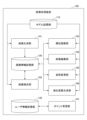
- FIG. 1 is a diagram showing an example of the functional configuration of an image processing apparatus.
- FIG. 2 is a diagram showing an example of a process selection screen.
- FIG. 3 is a diagram showing an example of a process selection screen.
- FIG. 4 is a diagram showing an example of an image generation screen.
- FIG. 5 is a diagram showing an example of an image generation screen.
- FIG. 6 is a diagram showing an example of an image generation screen.
- FIG. 7 is a diagram showing an example of an image generation screen.
- FIG. 8 is a diagram showing an example of a save confirmation screen.
- FIG. 9 is a diagram showing an example of an image fusion screen.
- FIG. 10 is a diagram showing an example of the image selection screen.
- FIG. 11 is a diagram showing an example of an image fusion screen.
- FIG. 12 is a diagram showing an example of an image fusion screen.
- FIG. 13 is a diagram showing an example of an attribute adjustment screen.
- FIG. 14 is a diagram showing an example of an attribute adjustment screen.
- FIG. 15 is a diagram showing an example of an attribute adjustment screen.
- FIG. 16 is a diagram showing an example of a help screen.
- FIG. 17 is a diagram showing an example of the image details screen.
- FIG. 18 is a diagram illustrating an example of a processing procedure of an image processing method;
- FIG. 19 is a diagram illustrating an example of the processing procedure of image fusion processing.
- FIG. 20 is a diagram illustrating an example of a hardware configuration of an image generation device;
- An image processing apparatus is an information processing apparatus that provides an image processing tool in which various image processes are integrated.
- the image processing tool in this embodiment can generate an image, adjust the attributes of an object included in the image, edit the image, change the posture of the object included in the image, and fuse a plurality of images as image processing.
- the object included in the image is a character (person).
- the object included in the image is not limited to this, and may be any object that can be represented by an image, such as animals, fictional creatures, robots, landscapes, and buildings.
- the image may be expressed in any form, such as an illustration style, a photograph style, computer graphics (CG: Computer Graphics), or the like.
- CG Computer Graphics
- the image may be used for moving images or may be used for animation.
- the image processing tool in this embodiment makes it possible to use an image generated by one image process in another image process.
- a plurality of images generated by image generation processing can be fused into one image by image fusion processing.
- an image generated by a method other than an image processing tool and an image generated by image generation processing can be merged into one image by image fusion processing.
- image fusion processing can be performed on an image obtained by attribute adjustment processing, image editing processing, or attitude change processing.
- attribute adjustment processing, image editing processing, attitude change processing, or image fusion processing can be performed on the fusion image generated by the image fusion processing.
- the image processing tool in this embodiment can use multiple generation models according to the characteristics of the image to be processed.
- An example of image features is the body part (for example, face, upper body, whole body, etc.), sex, clothes, etc. of a person included in the image.
- Another example of image characteristics is the type of object included in the image, the resolution of the image, the touch of the image, and the like.
- the units for preparing generative models are not limited to these, and generative models may be prepared according to other characteristics.
- the image processing tool in this embodiment implements predetermined image processing by inputting latent variables corresponding to the generative model into a trained generative model or an edited model trained to correspond to the generative model. do.
- the “latent variables according to the generative model” are, for example, latent variables belonging to the latent space of the generative model or latent variables linked to the generative model.
- a latent variable is information necessary for image generation using a generative model, and may be sampled from the probability distribution followed by variables input to the generative model during training. Also, the latent variable may be the latent information described in Patent Document 1. Also, the latent variable may be information including either a code or an attribute described in Patent Document 1. A latent variable is information input to a corresponding generative model, and may include information on noise, genes, attributes, or posture.
- the image processing tool in this embodiment can execute latent variable generation processing for generating latent variables from images.
- the latent variable generation process can generate latent variables belonging to the latent space of the generative model by inputting an image into an encoder model corresponding to the generative model.
- the encoder model may be a neural network trained for the generative model.
- the latent variable generation process can generate latent variables belonging to the latent space of the generative model by optimizing initial latent variables using the generative model.
- a method of specifying the initial latent variable may be a fixed value or a random value, but is not limited to them.
- the latent variables generated using the encoder model may be optimized using the generative model.
- the latent variable generation process is not limited to these, and any method may be used to generate latent variables in which the input image belongs to the latent space of the generative model.
- the image processing tool in this embodiment executes the latent variable generation process for one of the images when the latent variables of the multiple input images belong to different latent spaces of the generative models. , generate latent variables that belong to the latent space of the same generative model. Also, in the image fusion processing, the fusion processing may be executed using a plurality of latent variables linked to the same generative model.
- FIG. 1 is a block diagram showing an example of the functional configuration of an image processing apparatus according to this embodiment.
- the image processing apparatus 100 in this embodiment includes an image generation unit 101, an image fusion unit 102, an attribute adjustment unit 103, an image editing unit 104, a posture change unit 105, and a latent variable generation unit 106. , a point management unit 107 , a model storage unit 110 , an image information storage unit 120 and a user information storage unit 130 .
- the model storage unit 110 stores one or more trained generative models.
- the structure of the generative model may be a neural network or a deep neural network.
- the structure of the generative model and its training method are disclosed in Patent Literature 1 as an example.
- the model storage unit 110 stores the trained edit model and encoder model corresponding to the generative model.
- the editing model is disclosed in Patent Document 2 as an example.
- a known technique can be used as a method of training the encoder model.
- the image information storage unit 120 associates and stores an image, a latent variable of the image, and identification information for identifying the generative model that generated the image (for example, the name of the generative model, the ID of the generative model, etc.).
- the image stored in the image information storage unit 120 may be an image generated by the image processing apparatus 100 or an image generated by another method and uploaded to the image processing apparatus 100 .
- the user information storage unit 130 stores information about the user of the image processing tool.
- User information in this embodiment includes authentication information and contract information.
- Authentication information is information used to authenticate a user.
- An example of authentication information is a user ID that identifies the user and a password set by the user.
- the contract information includes information indicating the price plan subscribed by the user and information indicating the points owned by the user.
- the image generation unit 101 uses the generation model stored in the model storage unit 110 to generate a new image. Specifically, the image generator 101 first generates latent variables as random numbers.
- the image generation unit 101 generates an image by inputting the generated latent variables into the generation model. Then, the image generation unit 101 stores the generated image in the image information storage unit 120 in association with the identification information of the latent variable and the generative model.
- the image fusing unit 102 fuses at least two images using a generative model stored in the model storage unit 110 . Specifically, the image fusion unit 102 first generates a fusion latent variable by fusing the latent variable of the first image and the latent variable of the second image. Here, fusion involves using both the latent variables of the first image and the latent variables of the second image to generate a new latent variable (fused latent variable). Further, the image fusion unit 102 may generate fusion latent variables by applying a predetermined operation to the latent variables of the first image and the latent variables of the second image. The predetermined operation may be a genetic operation such as crossover, mutation, or selection on a latent variable, a predetermined synthetic operation such as four arithmetic operations, or a logic operation.
- the predetermined operation may be a genetic operation such as crossover, mutation, or selection on a latent variable, a predetermined synthetic operation such as four arithmetic operations, or a logic operation.
- the image fusion unit 102 generates a fusion image by inputting the fusion latent variable into the generation model. Then, the image fusion unit 102 stores the generated fusion image in the image information storage unit 120 in association with the identification information of the fusion latent variable and the generation model.
- Patent Document 1 Details of a method of fusing images using a generative model are disclosed in Patent Document 1 as an example. Note that the image fusion unit 102 may generate a fusion image by fusing three or more images.
- the attribute adjustment unit 103 uses the generative model stored in the model storage unit 110 to adjust attributes of objects included in the image. Specifically, the attribute adjustment unit 103 first receives input of an attribute value according to a user's operation. The input attribute value may be an absolute value of the attribute or a value relative to the attribute of the image. Next, the attribute adjustment unit 103 transforms the latent variables of the image so as to correspond to the received attribute values.
- attributes to be adjusted include the shape of a person's ears, eyes, mouth, etc., skin and eye color, hairstyle and hair color, posture such as arm positions and poses, facial expressions such as emotions, and clothing. type, color, shape, etc., accessories such as eyeglasses and hats.
- the attributes of the object are not limited to these, and any item may be defined as the attribute as long as it is meaningful for the user in changing the image of the target object.
- the attribute adjustment unit 103 inputs the converted latent variables to the generative model to generate an image whose attributes have been adjusted. Then, the attribute adjusting unit 103 associates the attribute-adjusted image with the converted latent variable and the identification information of the generative model, and stores the associated image in the image information storage unit 120 .
- the image editing unit 104 edits images using the editing model stored in the model storage unit 110 . Specifically, the image editing unit 104 first predicts a segmentation map and a latent variable for each segment region from the image to be edited. Next, the image editing unit 104 changes the segmentation map and/or the latent variable for each segment area according to the user's operation.
- the image editing unit 104 generates an edited image by inputting the modified segmentation map and latent variables into the editing model.
- the editing model may be a trained neural network.
- the image editing unit 104 stores the edited image in the image information storage unit 120 in association with the segmentation map, the latent variable for each segment area, and the identification information of the edit model.
- the latent variables for each segment area used in the edit model are different from the latent variables used in the generative model, but they can be converted to each other. Therefore, when an image edited by image editing processing is used in other image processing, the latent variables for each segment region may be converted into latent variables used in the generative model. Alternatively, the latent variables used in the generative model may be generated from the image edited by the image editing process by the latent variable generating process described later.
- Patent Document 2 Details of a method of editing an image using an editing model are disclosed in Patent Document 2 as an example.
- the pose changing unit 105 uses the generative model stored in the model storage unit 110 to change the pose of the object included in the image. Specifically, the posture changing unit 105 first receives an input of posture information representing the post-change posture in accordance with the user's operation. Next, posture changing unit 105 transforms the latent variables of the image so as to correspond to the received posture information.
- the posture changing unit 105 generates an image with the changed posture by inputting the transformed latent variables into the generation model. Then, the posture changing unit 105 stores the image whose posture has been changed in the image information storage unit 120 in association with the converted latent variables and the identification information of the generative model.
- the posture changing unit 105 may predict the posture of the image to be changed before accepting the user's input. This allows the user to easily specify the post-change posture.
- the latent variable generation unit 106 uses the encoder model stored in the model storage unit 110 to generate latent variables from the image. Specifically, the latent variable generator 106 predicts the latent variables of the generative model by inputting the image into the encoder model.
- the latent variable generation unit 106 may generate latent variables by optimizing initial latent variables using a generative model without using an encoder model.
- a method of specifying the initial latent variable may be a fixed value or a random value, but is not limited to them. Note that the latent variable generation unit 106 may optimize the latent variables predicted using the encoder model using the generative model. This allows the latent variables to better reflect the features of the image.
- the point management unit 107 manages the points owned by the user.
- the point management unit 107 subtracts (consumes) points according to the image processing used by the user.
- the image generation process, the image fusion process, and the latent variable generation process consume the first number of points
- the attribute adjustment process, the image editing process, and the posture change process consume the second number of points, which is smaller than the first number of points.
- the point management unit 107 performs processing for editing an existing image (attribute adjustment processing, image editing processing, posture change processing) in processing for generating a new image (image generation processing, image fusion processing, latent variable generation processing) ) are configured to consume a greater number of points than
- the image fusion process is a special process that fuses multiple images selected by the user, so the number of points consumed may be higher than for other image processes. That is, the point management unit 107 may consume a third number of points larger than the first number of points in the image fusion process.
- the point management unit 107 does not consume points (that is, the second number of points is 0) when executing attribute adjustment processing, image editing processing, and posture change processing, and saves images generated by these processing.
- a fourth number of points which is less than the first number of points, may be expended in doing so. As a result, the user can perform processing such as editing an existing image without worrying about point consumption.
- the classification of image processing that consumes the first number of points and image processing that consumes the second number of points is not limited to these, and can be arbitrarily selected.
- image fusion processing consumes a first number of points
- image generation processing, attribute adjustment processing, image editing processing, posture change processing, and latent variable generation processing consume a second number of points smaller than the first number of points.
- the point management unit 107 does not consume points when executing image generation processing, attribute adjustment processing, image editing processing, attitude change processing, and latent variable generation processing (that is, the second number of points is 0). ), a fifth number of points, which is less than the first number of points, may be expended in saving the images produced by these processes.
- the points held by the user are determined as follows. When a user makes a new contract, points are given according to the price plan. There are a free plan and a subscription plan, and the subscription plan is paid. Even if points are consumed, they will recover after a certain period of time. It is also possible to purchase additional points for a fee. The maximum number of points that a user can have and the point recovery speed differ depending on the billing plan.
- the point management unit 107 consumes a large number of points in the process of generating a new image and consumes a small number of points in the process of editing an existing image, so that the following effects are expected.
- FIG. 2 The user interface can be implemented as an operation screen provided to the user terminal by the image processing apparatus 100, for example.
- FIG. 2 is a diagram showing an example of a processing selection screen for selecting image processing.
- the process selection screen 1000 has activation buttons 1001 to 1006 corresponding to each image process.
- image processing corresponding to the activation button is executed.
- the number of activation buttons displayed on the processing selection screen 1000 can be changed according to the type of image processing provided by the image processing tool.
- the activation button 1001 (Generate) activates the image generation unit 101 to execute image generation processing.
- An activation button 1002 (fusion) activates the image fusion unit 102 to execute image fusion processing.
- An activation button 1003 (attribute adjustment) activates the attribute adjustment unit 103 to execute attribute adjustment processing.
- An activation button 1004 (canvas) activates the image editing unit 104 to execute image editing processing.
- An activation button 1005 (pause) activates the posture change unit 105 to execute posture change processing.
- a start button 1006 (make latent variable) starts the latent variable generation unit 106 to execute latent variable generation processing.
- FIG. 3 is a diagram showing an example when the process selection screen 1000 is deformed vertically. As shown in FIG. 3, when the shape of the entire process selection screen 1000 is changed, the arrangement of the activation buttons may be changed. At this time, it is preferable to control so that the activation button 1001 corresponding to the image generation process is always positioned at the upper left of the screen.
- an authentication screen for authenticating the user Prior to displaying the process selection screen 1000, an authentication screen for authenticating the user may be displayed.
- the authentication screen accepts input of authentication information such as a user ID and a password, and transmits the input to the image processing apparatus 100 according to the user's operation.
- the image processing apparatus 100 performs authentication using the received authentication information based on the user information stored in the user information storage unit 130 .
- the image processing apparatus 100 displays the process selection screen 1000 on the terminal of the user who has been successfully authenticated.
- FIG. 4 is a diagram showing an example of an image generation screen for generating an image.
- the image generation screen 1100 has a model selection field 1101, an image selection area 1102, a generation button 1103 and a save button 1104.
- names of generative models stored in the model storage unit 110 are displayed in a drop-down list so that they can be selected.
- the image generating unit 101 newly generates an image using the selected generative model.
- FIG. 5 is a diagram showing an example when the image generation screen 1100 is deformed vertically. As shown in FIG. 5, when the shape of the entire image generation screen 1100 is changed, the arrangement of the image selection areas 1102 may be changed.
- FIG. 6 is a diagram showing an example of an image generation screen 1100 after generating an image. As shown in FIG. 6 , on the image generation screen 1100 after image generation, an image generated using the generation model selected in the model selection field 1101 is displayed in the image selection area 1102 .
- the image generation screen 1100 after image generation shown in FIG. 6 is an example when a generation model whose processing target is a face image is selected. For example, when a generation model for processing a whole body image is selected, the generated whole body image is displayed in the image selection area 1102 .
- the types of images displayed on each screen described below are not limited unless otherwise specified.
- the image generation unit 101 may generate a plurality of images and display them in the image selection area 1102 . Also, the number of images to be generated can be arbitrarily determined. When generating a plurality of images, the image generating unit 101 generates a plurality of random latent variables and inputs them to the generative model.
- FIG. 7 is a diagram showing an example of the image generation screen 1100 when the generated image is enlarged and displayed in the enlarged image display area 1105.
- FIG. 7 when the user designates the fourth image displayed from the left in the top row of the image selection area 1102 shown in FIG. 6, that image is enlarged and displayed in the enlarged image display area 1105. .
- Symbols “ ⁇ ” and “>” may be displayed on the left and right sides of the enlarged image display area 1105 .
- the image displayed in the enlarged image display area 1105 is changed to the previous image of the enlarged image (in the example of FIG.
- the save confirmation screen shown in FIG. 8 is displayed. Note that the number of images that can be selected by the user may be plural, and the selectable upper limit may be arbitrarily set.
- FIG. 8 is a diagram showing an example of a save confirmation screen.
- the image generation unit 101 identifies the image selected in the image selection area 1102 by identifying the latent variable of the image and the generative model used to generate the image.
- the information is stored in the image information storage unit 120 in association with the information.
- FIG. 9 A user interface in image fusion processing will be described with reference to FIGS. 9 to 12.
- FIG. 9 A user interface in image fusion processing will be described with reference to FIGS. 9 to 12.
- FIG. 9 is a diagram showing an example of an image fusion screen for fusing images.
- the image fusion screen 1200 has a first image selection field 1201 and a second image selection field 1202 .
- the image selection screen shown in FIG. 10 is displayed.
- FIG. 10 is a diagram showing an example of the image selection screen.
- image selection screen 1210 has image selection area 1211 and filter button 1212 .
- An image stored in the image information storage unit 120 is displayed in the image selection area 1211 .
- the name of the generative model that generated the image may be displayed together with the image.
- the user can narrow down the images to be displayed in the image selection area 1211 by setting filters from the filter button 1212 .
- An example of a filter is a generative model associated with an image. That is, by specifying a generative model with a filter, the user can display only images generated by the generative model.
- the image selection area 1211 of the image selection screen 1210 when the user selects an arbitrary image (hereinafter also referred to as “first image”), the selected first image is displayed in the first image selection field 1201 of the image fusion screen 1200 . Is displayed.
- first image an arbitrary image
- the image selection screen 1210 shown in FIG. 10 is displayed.
- the user selects an arbitrary image (hereinafter also referred to as a “second image”) in the image selection area 1211 of the image selection screen 1210
- the selected second image is displayed in the second image selection field 1202 of the image fusion screen 1200 . Is displayed.
- the image selection screen 1210 may perform control so that only images generated by the same generation model as the first image can be selected. For example, the image selection screen 1210 may set the generative model associated with the first image as a filter. As a result, only images generated by the same generation model as the first image are displayed in the image selection area 1211 .
- the image selection screen 1210 displays a warning screen indicating that the images cannot be fused. may be controlled so that it cannot be selected.
- the user can use latent variable generation processing to manually generate latent variables from the second image according to the same generation model as the first image.
- the generated latent variable (corresponding to the same generative model as the first image), the identification information of the same generative model as the first image, and the image generated using both are associated with each other, and stored in the image information storage unit 120. You can remember.
- the image selection screen 1210 may allow selection of an image generated by a generation model different from that of the first image.
- the image fusion unit 102 may automatically generate latent variables according to the same generation model as the first image from the second image using latent variable generation processing.
- the generated latent variable (corresponding to the same generative model as the first image), the identification information of the same generative model as the first image, and the image generated using both are associated with each other, and stored in the image information storage unit 120. You can remember.
- FIG. 11 is a diagram showing an example of the image fusion screen after selecting two images. As shown in FIG. 11, the image fusion screen 1200 after image selection has a first image selection field 1201, a second image selection field 1202, a generate button 1203 and a save button 1204. FIG.
- the first image and second image selected on the image selection screen 1210 are displayed in the first image selection field 1201 and the second image selection field 1202 .
- the image fusing unit 102 fuses the first image and the second image using the generative model associated with the first image.
- FIG. 12 is a diagram showing an example of an image fusion screen 1200 after images have been merged. As shown in FIG. 12, the image fusion screen 1200 after image fusion has a generate button 1203, a save button 1204, an image display area 1205, and an image selection area 1206. FIG. 12
- the image display area 1205 displays the first image and the second image before fusion.
- An image selection area 1206 displays a fused image obtained by merging the first image and the second image.
- Each fusion image may be displayed larger than each of the first and second images so that the user can grasp the details of the image better than the first and second images.
- the image fusion unit 102 may generate a plurality of fusion images and display them in the image selection area 1206, and the number of images to be generated can be arbitrarily determined. Note that when the image fusion processing has randomness, the image fusion unit 102 may generate a plurality of fusion images by repeatedly executing the image fusion processing a plurality of times. Also, the image fusion unit 102 may generate a plurality of fusion images by performing different genetic operations on the latent variables of the first image and the latent variables of the second image.
- the image fusion unit 102 fuses the images again, and the image selection area 1206 is updated.
- the save confirmation screen shown in FIG. 8 is displayed. Note that the number of images that can be selected by the user may be plural, and the selectable upper limit may be arbitrarily set.
- the image fusion unit 102 identifies the fusion image selected in the image selection area 1206 by identifying the latent variables of the fusion image and the generative model used to generate the image.
- the information is stored in the image information storage unit 120 in association with the information.
- FIG. 13 is a diagram showing an example of an attribute adjustment screen for adjusting attributes of objects included in an image.
- the attribute adjustment screen 1300 has an image selection column 1301, a result display column 1302, a change button 1303 and a save button 1304.
- FIG. 13 is a diagram showing an example of an attribute adjustment screen for adjusting attributes of objects included in an image.
- the attribute adjustment screen 1300 has an image selection column 1301, a result display column 1302, a change button 1303 and a save button 1304.
- FIG. 13 is a diagram showing an example of an attribute adjustment screen for adjusting attributes of objects included in an image.
- the attribute adjustment screen 1300 has an image selection column 1301, a result display column 1302, a change button 1303 and a save button 1304.
- the image selection screen shown in FIG. 10 is displayed.
- an attribute adjustment screen shown in FIG. 14 is displayed.
- FIG. 14 is a diagram showing an example of the attribute adjustment screen after selecting an image.
- an attribute value designation panel 1305 is displayed on the attribute adjustment screen 1300 after image selection.
- a base image is displayed in the image selection field 1301 .
- the attribute value designation panel 1305 displays adjustable attributes. Adjustable attributes may be hierarchically displayed, and in the example of FIG. 14, hair color "Hair Color”, eye color “Eye Color”, and other attributes "Others" are hierarchically displayed as adjustable attributes. be.
- FIG. 15 is a diagram showing an example of an attribute adjustment screen after adjusting attributes.
- the attribute value designation panel 1305 displays the current value of each attribute so that it can be changed with a slider bar.
- the user can change any attribute value with a slider bar on the attribute value specification panel 1305 .
- the example of FIG. 15 indicates that the attribute value of the "long_hair" attribute has been changed to 1.26.
- the content of this change (the adjusted attribute and its attribute value) may be displayed in the area above the attribute value designation panel 1305, such as the display "long_hair: 1.26".
- a method for changing the attribute value for example, a method by which the user directly inputs a numerical value that will be the attribute value, or a method by which the user presses a button to increase or decrease the current attribute value by a constant value. method etc. may be adopted.
- the attribute adjustment unit 103 converts the latent variable of the base image according to the attribute value designated on the attribute value designation panel 1305. . Then, the attribute adjustment unit 103 inputs the converted latent variables to the generative model associated with the image, thereby generating the attribute-adjusted image. The generated attribute-adjusted image is displayed in the result display field 1302 .
- the save confirmation screen shown in FIG. 8 is displayed.
- the attribute adjustment unit 103 identifies the image after attribute adjustment displayed in the result display field 1302 as the latent variable of the image and the generative model used to generate the image. It is stored in the image information storage unit 120 in association with the identification information.
- the image editing screen has a segmentation map display field, a result display field, a selected image display field, a reference image display field, an apply button, and an add button.
- the segmentation map display column and the result display column may be displayed side by side near the center of the screen.
- the selected image display column and the reference image display column may be displayed vertically arranged at the right end of the screen.
- the segmentation map display field and the result display field may be displayed larger than the selected image display field and the reference image display field.
- the apply button and the add button may be displayed side by side at the bottom of the screen.
- the image selection screen shown in FIG. 10 is displayed.
- the segmentation map of the base image is displayed in the segmentation map display field.
- the base image is displayed in the selected image display column.
- the user may select a reference image on the image editing screen.
- a reference image is an image that is applied to verify the edited segmentation map.
- the user presses the reference image display field.
- the image selection screen shown in FIG. 10 is displayed.
- the reference image is displayed in the reference image display field.
- the edit button the edited segmentation map displayed in the segmentation map display field is applied to the reference image displayed in the reference image display field and displayed in the result display field.
- the image editing unit 104 first predicts latent variables for each segment from the reference image. Next, the image editing unit 104 transforms the latent variables for each segment of the reference image according to the segmentation map displayed in the segmentation map display field.
- the image editing unit 104 generates an edited image by inputting the converted latent variables for each segment into the editing model corresponding to the generation model associated with the base image. Then, the image editing unit 104 displays the edited image in the result display field.
- the user edits the image using the toolbar and layer list displayed on the image editing screen.
- the toolbar may be displayed on the left edge of the screen and the layer list may be displayed on the right edge of the screen.
- the toolbar is a panel for selecting tools for editing the segmentation map.
- the layer list is a layer list for selecting a layer of the segmentation map to be edited. The user selects a layer to be edited from the layer list, selects a tool from the tool bar, and then edits the selected layer from the segmentation map display field.
- the mix ratio specification field When you right-click on a specific layer in the layer list, the mix ratio specification field will be displayed. Using the mix ratio designation field, it is possible to adjust the mix ratio between the base image and the reference image.
- the edit button When the user presses the apply button, the edited segmentation map displayed in the segmentation map display field is applied to the reference image displayed in the reference image display field.
- the image editing unit 104 adds the edited image displayed in the result display field to the segmentation map after editing, the latent variables for each layer of the image, and the identification information for identifying the editing model. , and stored in the image information storage unit 120 .
- the posture change screen has an image selection column, a result display column, a change button, and a save button.
- the image selection field may be displayed on the upper left of the screen.
- the result display field may be displayed near the center of the screen.
- the result display field may be displayed larger than the image selection field.
- the change button and the save button may be displayed side by side at the bottom of the screen.
- the image selection screen shown in FIG. 10 is displayed.
- the base image is displayed in the image selection field.
- posture information connecting indirect points extracted from the base image is displayed.
- the posture change screen after image selection further has a reference image selection field.
- the image selection screen shown in FIG. 10 is displayed.
- the reference image is displayed in the reference image selection field.
- the posture information displayed in the result display field is updated to the posture information extracted from the reference image displayed in the reference image selection field.
- the orientation information may be changed by manually moving the contact point in the result display field without selecting the reference image in the reference image selection field.
- the posture changing unit 105 converts the latent variables of the image selected in the image selection field according to the posture information displayed in the result display field.
- the attitude changing unit 105 generates an image after the attitude change by inputting the converted latent variables into the generation model associated with the image.
- the image after the posture change is displayed in the result display column.
- the posture changing unit 105 associates the image displayed in the result display field with the latent variables of the image and the identification information that identifies the generative model used to generate the image, and stores the image in the image information storage unit. store in 120;
- the latent variable generation screen has a model selection column, an image selection column, a result display column, an apply button, and a save button.
- the model selection field may be displayed on the upper left of the screen.
- the image selection column and the result display column may be displayed side by side near the center of the screen.
- the apply button and the save button may be displayed side by side at the bottom of the screen.
- model selection column names of generative models stored in the model storage unit 110 are displayed in a drop-down list so that they can be selected.
- image selection field an image selection screen for selecting an image file is displayed.
- the selected image file is uploaded to the image processing apparatus 100, and the uploaded image is displayed in the image selection field.
- the latent variable generation unit 106 uses the encoder model corresponding to the selected generative model to generate a latent variable from the image displayed in the image selection field. to generate Note that a known technique may be used to generate the latent variables.
- the latent variable generation unit 106 When the latent variable generation unit 106 generates a latent variable, an image corresponding to the generated latent variable is displayed in the result display column. Specifically, the latent variable generator 106 generates an image by inputting the generated latent variables into the selected generative model. Then, the latent variable generation unit 106 displays the generated image in the result display field.
- the latent variable generation unit 106 associates the image displayed in the result display field with the generated latent variable and the identification information that identifies the generative model used for generation, and stores the image information in the image information storage unit. store in 120;
- Point information owned by the authenticated user may be displayed on the user interface of the image processing apparatus 100 .
- a display example of the point information will be described with reference to FIGS. 16 and 17.
- FIG. 16 and 17 A display example of the point information will be described with reference to FIGS. 16 and 17.
- FIG. 16 is a diagram showing an example of a help screen for displaying how to operate the image processing tool.
- the help screen 1700 has buttons for displaying explanations of each function.
- the help screen 1700 also has a point display field 1701 and an add point button 1702 .
- a point display field 1701 displays the number of points possessed by the user and the maximum number of points that the user can possess.
- the point addition button 1702 When the user presses the point addition button 1702, a billing screen for purchasing points is displayed.
- the point display column 1701 may be displayed on the processing selection screen or the screen for each image processing.
- FIG. 17 is a diagram showing an example of an image detail screen for displaying detailed image information.
- the image details screen 1800 displays detailed information such as image profile, comments, and tags.
- the image details screen 1800 also has a point display field 1801 and an add point button 1802 .
- the functions of the point display field 1801 and the add point button 1802 are the same as those of the point display field 1701 and the add point button 1702 of the help screen 1700 .
- FIG. 18 is a flow chart showing an example of the processing procedure of the image processing method.
- step S1 the image generation unit 101 newly generates an image using the generation model stored in the model storage unit 110 according to the user's operation.
- the point management unit 107 subtracts a predetermined number of points (hereinafter also referred to as "first number of points") from the points owned by the user.
- step S2 the image generation unit 101 stores the generated image in the image information storage unit 120 in association with the identification information of the latent variable and the generation model.
- step S3 the image processing apparatus 100 determines image processing to be executed next according to the user's operation. Specifically, when a start button 1002 to 1005 is pressed on the process selection screen 1000 shown in FIG. 2 or 3, image processing corresponding to the start button is executed.
- step S4 When the start button 1003 (attribute adjustment process) is pressed, the image processing apparatus 100 advances the process to step S4.
- step S6 When the start button 1004 (image editing process) is pressed, the image processing apparatus 100 advances the process to step S6.
- step S8 When the activation button 1002 (image fusion processing) is pressed, the image processing apparatus 100 advances the processing to step S10.
- step S4 the attribute adjustment unit 103 adjusts the attributes of the object included in the image using the generative model stored in the model storage unit 110 according to the user's operation.
- the point management unit 107 subtracts a predetermined number of points (hereinafter referred to as "second number of points") from the points owned by the user. Note that the second number of points is set smaller than the first number of points.
- step S5 the attribute adjustment unit 103 stores the attribute-adjusted image in the image information storage unit 120 in association with the converted latent variable and the identification information of the generative model.
- step S6 the image editing unit 104 edits the image using the editing model stored in the model storage unit 110 according to the user's operation.
- step S6 the point management unit 107 subtracts the second number of points from the points owned by the user.
- step S7 the image editing unit 104 stores the edited image in the image information storage unit 120 in association with the converted latent variables and the identification information of the editing model used for image editing.
- step S8 the posture changing unit 105 changes the posture of the object included in the image using the generative model stored in the model storage unit 110 according to the user's operation.
- the point management unit 107 subtracts the second number of points from the points owned by the user.
- step S9 the posture changing unit 105 stores the image whose posture has been changed in the image information storage unit 120 in association with the transformed latent variables and the identification information of the generative model.
- step S10 the image fusing unit 102 fuses at least two images using the generative model stored in the model storage unit 110 according to the user's operation.
- the point management unit 107 subtracts the first number of points from the points owned by the user.
- step S11 the image fusion unit 102 stores the generated fusion image in the image information storage unit 120 in association with the identification information of the fusion latent variable and the generation model.
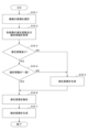
- FIG. 19 is a flowchart showing an example of the procedure of image fusion processing.
- the image fusing unit 102 accepts selection of a plurality of images according to the user's operation.
- the plurality of images to be selected may be images stored in the image information storage unit 120 or may be images uploaded by the user.
- the generation models that generated the images may be the same or different.
- step S10-2 the image fusing unit 102 acquires identification information for identifying latent variables and generative models stored in the image information storage unit 120 for each of the plurality of received images. Note that if the received image has been uploaded by the user, the identification information of the latent variables and the generative model cannot be acquired, but the subsequent processing is executed as it is.
- step S10-3 the image fusing unit 102 determines whether the latent variables of each image have been acquired. If the latent variables of all images have been acquired (YES), the image fusing unit 102 advances the process to step S10-4. On the other hand, if the latent variables of one of the images could not be acquired (NO), the image fusion unit 102 identifies the generative models of the one image for which the latent variables could not be acquired and the other image for which the latent information could be acquired. information is sent to the latent variable generation unit 106, and the process proceeds to step S10-5.
- step S10-4 the image fusion unit 102 determines whether or not the identification information of the generative model of each image matches. If the identification information of the generative models of all the images match (YES), the image fusing unit 102 advances the process to step S10-6. On the other hand, if the identification information of the generative models of any of the images is different (NO), the image fusing unit 102 transmits the identification information of the generative models of the one image and the other image having different identification information to the latent variable generating unit 106. and advance the process to step S10-5.
- step S10-5 the latent variable generation unit 106 identifies the generative model from the identification information received from the image fusion unit 102, and identifies the encoder model corresponding to the generative model.
- the latent variable generation unit 106 generates latent variables by inputting the image received from the image fusion unit 102 to the specified encoder model.
- generative models may be used to generate latent variables.
- step S10-6 the image fusion unit 102 generates a fusion latent variable by fusing the latent variables of the selected multiple images. However, when latent variables are generated in step S10-5, the latent variables of the other image and the generated latent variables are merged.
- step S10-7 the image fusion unit 102 generates a fusion image by inputting the fusion latent variable into the generation model.
- a generative model is a generative model specified by the identification information of the generative model of each image.
- the image, the latent variable, and the identification information of the generative model are stored in association with each other. good.
- the corresponding image may be regenerated from the latent variables and the generative model when necessary, such as when a display request is received.
- “Storing the latent variables in association with the identification information of the generative model” includes both direct and indirect storage.
- the latent variable and the identification information of the generative model may be stored as a set of data, or the latent variable may be given the identification information of the generative model and stored.
- "store the latent variables and image identification information (image name, image ID, etc.) in association with each other, and store the identification information of the same image in association with the identification information of the generative model”. may In this case, the latent variables and the corresponding generative model identification information can be called based on the image identification information.
- the latent variables and the generative model itself may be stored as a set. Any method may be used as long as it is possible to call the correspondence between the "latent variables” and the "corresponding generative models” in subsequent processing.
- Each user interface shown in FIGS. 2 to 17 may be displayed on a terminal (eg, PC, smartphone, etc.) directly operated by the user.
- a terminal eg, PC, smartphone, etc.
- the user information storage unit 130 may store the identification information of the user and the identification information of the image owned by the user as a set. In this case, each image process may be restricted so that only images associated with the user can be called as processing targets.
- the image processing apparatus 100 stores the latent variables of the image in association with the identification information that identifies the generative model, thereby enabling the image to be shared among various image processes.
- image fusion processing multiple images to be fused must belong to the latent space of the same generative model or be linked to the same generative model.
- appropriate image fusion processing can be executed by associating the identification information of the
- appropriate image processing can be performed by using the generative model associated with the latent variables.
- latent variables corresponding to the same generative model can be generated by executing latent variable generation processing. .
- the image processing apparatus 100 When executing image fusion processing, the image processing apparatus 100 according to the present embodiment can select an image to be fused from images filtered based on the generation model. This allows the fusion process to be performed using multiple latent variables corresponding to the same generative model.
- the image processing apparatus 100 can motivate users to use image processing tools by setting consumption points according to image processing. As a result, it becomes possible to get the user to consume more points.
- the image processing apparatus 100 When executing image generation processing, the image processing apparatus 100 according to the present embodiment stores, as an example, image identification information, latent variables, corresponding generation model identification information, and generated images. At this time, it is possible to arbitrarily decide whether or not to store the image identification information and the generated image.
- the image processing apparatus 100 executes the image fusion process, as an example, the image identification information, the latent variable after fusion, the identification information of the corresponding generative model, the generated fusion image, and the Store image identification information for the two images.
- the image identification information of the image used for fusion is stored, the identification information of the latent variable of the original image and the identification information of the generative model can be obtained from the image identification information.
- the image processing apparatus 100 executes the attribute adjustment process, for example, the image identification information, the latent variable after attribute adjustment, the identification information of the corresponding generative model, the generated image after attribute adjustment,
- the image identification information of the image before attribute adjustment is stored. At this time, it is possible to arbitrarily decide whether or not to store the identification information of the image, the generated image after attribute adjustment, and the image identification information of the image before attribute adjustment.
- the latent variables of the image before attribute adjustment and the identification information of the generative model can be obtained from the image identification information.
- the image processing apparatus 100 executes the attitude change process, for example, the image identification information, the latent variable after the attitude change, the identification information of the corresponding generative model, the generated image after the attitude change,
- the image identification information of the image before the attitude change is stored. At this time, it is possible to arbitrarily decide whether or not to store the identification information of the image, the generated image after the attitude change, and the image identification information of the image before the attitude change.
- the image identification information of the image before the attitude change is stored, the latent variables of the image before the attitude change and the identification information of the generative model can be obtained from the image identification information.
- the image processing apparatus 100 executes the latent variable generation process, for example, the image identification information, the generated latent variables, the corresponding generative model identification information, and the generated latent variables are transferred to the corresponding generative models. It stores an image generated by input, the original image used to generate the latent variables, and the identification information of the encoder model used to generate the latent variables. At this time, whether or not to store the image generated by inputting the generated latent variables into the corresponding generative model, the original image used to generate the latent variables, and the identification information of the encoder model used to generate the latent variables. It can be determined arbitrarily.
- the image processing apparatus 100 executes image editing processing, for example, image identification information, post-editing latent variables, corresponding editing model identification information, segmentation map, post-editing image, pre-editing image identification information of the image.
- image editing processing for example, image identification information, post-editing latent variables, corresponding editing model identification information, segmentation map, post-editing image, pre-editing image identification information of the image.
- the latent variables of the pre-edited image and the identification information of the generative model can be obtained from the image identification information.
- the image processing apparatus 100 may execute attribute adjustment processing, posture change processing, and image fusion processing using the stored latent variables and corresponding generative models. .
- the image processing apparatus 100 in the present embodiment uses the stored latent variables and the corresponding generative models to perform attribute adjustment processing, attitude change processing, image fusion processing (that is, the same image processing). ) may be executed.
- the image processing apparatus 100 in the present embodiment uses the stored latent variables and the corresponding generative models to perform posture change processing, image fusion processing, and attribute adjustment processing (that is, the same image processing). ) may be executed.
- the image processing apparatus 100 After executing the posture change processing, the image processing apparatus 100 according to the present embodiment performs attribute adjustment processing, image fusion processing, posture change processing (that is, the same image processing) using the stored latent variables and corresponding generative models. ) may be executed.
- the latent variable generation process may be executed at the following timing.
- the first timing is when different generation models are used for generation between images to be fused.
- the second timing is before executing attribute adjustment processing, attitude change processing, and image fusion processing for an image such as a user-designated image that does not have a latent variable.
- the processing may be executed using the "generative model" specified by the "latent variable” and the identification information of the generative model stored in association with it. At least during image generation processing, image fusion processing, attribute adjustment processing, and attitude change processing, processing may be executed using the same generative model and corresponding latent variables. Also, in the latent variable generation process, the same generative model may be used to generate latent variables.
- the image processing apparatus 100 in this embodiment may be configured with one or more storage devices and one or more processors. In this case, one or more processors can control storage of various data in one or more storage devices and acquisition of various data from one or more storage devices. The one or more processors may also control screens displayed on the display device.
- each device (image processing device 100) in the above-described embodiment may be configured by hardware, or may be software executed by CPU (Central Processing Unit), GPU (Graphics Processing Unit), etc. program) information processing.
- software information processing software that realizes at least part of the functions of each device in the above-described embodiments may be stored in a CD-ROM (Compact Disc-Read Only Memory), USB (Universal Serial Bus) memory.
- Information processing of the software may be executed by storing it in a non-temporary storage medium (non-temporary computer-readable medium) such as the above and reading it into a computer.
- the software may be downloaded via a communication network.
- all or part of the software processing may be implemented in a circuit such as an ASIC (Application Specific Integrated Circuit) or an FPGA (Field Programmable Gate Array), so that the information processing by the software may be executed by hardware. .
- the storage medium that stores the software may be removable such as an optical disc, or may be a fixed storage medium such as a hard disk or memory. Also, the storage medium may be provided inside the computer (main storage device, auxiliary storage device, etc.) or may be provided outside the computer.
- FIG. 20 is a block diagram showing an example of the hardware configuration of each device (image processing device 100) in the above-described embodiment.
- Each device includes, for example, a processor 71, a main storage device 72 (memory), an auxiliary storage device 73 (memory), a network interface 74, and a device interface 75, which are connected via a bus 76.
- a processor 71 for example, a main storage device 72 (memory), an auxiliary storage device 73 (memory), a network interface 74, and a device interface 75, which are connected via a bus 76.
- a computer 7 implemented as
- the computer 7 in FIG. 20 has one component, it may have a plurality of the same components.
- the software is installed in a plurality of computers, and each of the plurality of computers executes the same or different part of the processing of the software. good too.
- it may be in the form of distributed computing in which each computer communicates via the network interface 74 or the like to execute processing.
- each device (image processing device 100) in the above-described embodiment is configured as a system in which one or more computers execute commands stored in one or more storage devices to realize functions. good too.
- the information transmitted from the terminal may be processed by one or more computers provided on the cloud, and the processing result may be transmitted to the terminal.
- each device (image processing device 100) in the above-described embodiment may be executed in parallel using one or more processors or using multiple computers via a network. Also, various operations may be distributed to a plurality of operation cores in the processor and executed in parallel. Also, part or all of the processing, means, etc. of the present disclosure may be realized by at least one of a processor and a storage device provided on a cloud capable of communicating with the computer 7 via a network. Thus, each device in the above-described embodiments may be in the form of parallel computing by one or more computers.
- the processor 71 may be an electronic circuit (processing circuit, processing circuitry, CPU, GPU, FPGA, ASIC, etc.) that performs at least computer control or computation.
- Processor 71 may also be a general-purpose processor, a dedicated processing circuit designed to perform a particular operation, or a semiconductor device containing both a general-purpose processor and dedicated processing circuitry.
- the processor 71 may include an optical circuit, or may include an arithmetic function based on quantum computing.
- the processor 71 may perform arithmetic processing based on data and software input from each device, etc. of the internal configuration of the computer 7, and may output calculation results and control signals to each device, etc.
- the processor 71 may control each component of the computer 7 by executing the OS (Operating System) of the computer 7, applications, and the like.
- OS Operating System
- Each device (image processing device 100 ) in the above-described embodiment may be realized by one or more processors 71 .
- the processor 71 may refer to one or more electronic circuits arranged on one chip, or one or more electronic circuits arranged on two or more chips or two or more devices. You can point When multiple electronic circuits are used, each electronic circuit may communicate by wire or wirelessly.
- the main storage device 72 may store commands and various data executed by the processor 71 , and the information stored in the main storage device 72 may be read by the processor 71 .
- the auxiliary storage device 73 is a storage device other than the main storage device 72 . These storage devices mean any electronic components capable of storing electronic information, and may be semiconductor memories. Semiconductor memory may be either volatile memory or non-volatile memory.
- a storage device for storing various data and the like in each device (image processing device 100) in the above-described embodiments may be implemented by the main storage device 72 or the auxiliary storage device 73, and may be implemented by a built-in memory built into the processor 71. may be realized by For example, the model storage unit 110, the image information storage unit 120, and the user information storage unit 130 in the above-described embodiments may be realized by the main storage device 72 or the auxiliary storage device 73.
- each device (image processing device 100) in the above-described embodiment is composed of at least one storage device (memory) and at least one processor connected (coupled) to this at least one storage device
- the storage device At least one processor may be connected to one.
- At least one storage device may be connected to one processor.
- at least one processor among the plurality of processors may be connected to at least one storage device among the plurality of storage devices.
- This configuration may also be implemented by storage devices and processors included in multiple computers.
- a configuration in which a storage device is integrated with a processor for example, a cache memory including an L1 cache and an L2 cache may be included.
- the network interface 74 is an interface for connecting to the communication network 8 wirelessly or by wire. As for the network interface 74, an appropriate interface such as one conforming to existing communication standards may be used. The network interface 74 may exchange information with the external device 9A connected via the communication network 8 .
- the communication network 8 may be any one or a combination of WAN (Wide Area Network), LAN (Local Area Network), PAN (Personal Area Network), etc., and between the computer 7 and the external device 9A It may be anything as long as information is exchanged. Examples of WANs include the Internet, examples of LANs include IEEE 802.11 and Ethernet (registered trademark), and examples of PANs include Bluetooth (registered trademark) and NFC (Near Field Communication).
- the device interface 75 is an interface such as USB that directly connects with the external device 9B.
- the external device 9A is a device connected to the computer 7 via a network.
- the external device 9B is a device that is directly connected to the computer 7. FIG.
- the external device 9A or the external device 9B may be an input device.
- the input device is, for example, a device such as a camera, microphone, motion capture, various sensors, keyboard, mouse, touch panel, etc., and provides the computer 7 with acquired information.
- a device such as a personal computer, a tablet terminal, a smartphone, or the like that includes an input unit, a memory, and a processor may be used.
- the external device 9A or the external device B may be an output device as an example.
- the output device may be, for example, a display device such as an LCD (Liquid Crystal Display) or an organic EL (Electro Luminescence) panel, or a speaker or the like for outputting sound.
- a device such as a personal computer, a tablet terminal, or a smartphone including an output unit, a memory, and a processor may be used.
- the external device 9A or the external device 9B may be a storage device (memory).
- the external device 9A may be a network storage or the like, and the external device 9B may be a storage such as an HDD.
- the external device 9A or the external device 9B may be a device having the functions of some of the components of each device (image processing device 100) in the above-described embodiment. That is, the computer 7 may transmit part or all of the processing result to the external device 9A or the external device 9B, or may receive part or all of the processing result from the external device 9A or the external device 9B. .
- the expression "at least one (one) of a, b and c" or "at least one (one) of a, b or c" includes any of a, b, c, a-b, ac, b-c or a-b-c. Also, multiple instances of any element may be included, such as a-a, a-b-b, a-a-b-b-c-c, and so on. It also includes the addition of other elements than the listed elements (a, b and c), such as having d such as a-b-c-d.
- connection and “coupled” when used, they refer to direct connection/coupling, indirect connection/coupling , electrically connected/coupled, communicatively connected/coupled, operatively connected/coupled, physically connected/coupled, etc. intended as a term.
- the term should be interpreted appropriately according to the context in which the term is used, but any form of connection/bonding that is not intentionally or naturally excluded is not included in the term. should be interpreted restrictively.
- the physical structure of element A is such that it is capable of performing operation B configuration, including that a permanent or temporary setting/configuration of element A is configured/set to actually perform action B good.
- element A is a general-purpose processor
- the processor has a hardware configuration capable of executing operation B, and operation B is performed by setting a permanent or temporary program (instruction). It just needs to be configured to actually run.
- the element A is a dedicated processor, a dedicated arithmetic circuit, etc., regardless of whether or not the control instructions and data are actually attached, the circuit structure of the processor, etc., is such that the operation B is actually executed. It just needs to be built (implemented).
- finding a global optimum finding an approximation of a global optimum
- finding a local optimum Including seeking, and finding an approximation of a local optimum, should be interpreted appropriately depending on the context in which the term is used. It also includes stochastically or heuristically approximating these optimum values.
- each piece of hardware may work together to perform the predetermined processing, or a part of the hardware may perform the predetermined processing. You may do all of Also, some hardware may perform a part of the predetermined processing, and another hardware may perform the rest of the predetermined processing.
- expressions such as "one or more hardware performs the first process, and the one or more hardware performs the second process" (including similar expressions ) is used, the hardware that performs the first process and the hardware that performs the second process may be the same or different. In other words, the hardware that performs the first process and the hardware that performs the second process may be included in the one or more pieces of hardware.
- the hardware may include electronic circuits, devices including electronic circuits, and the like.
- each of the plurality of storage devices may store only part of the data. , may store the entire data. Further, a configuration may be included in which some of the plurality of storage devices store data.
- references to a first element and a second element indicate that only two elements may be employed therein, that the first element must precede the second element, that the second element does not necessarily mean that the first element must be present in order for a to be present, and so on.
- Image processing device 101 Image generation unit 102 Image fusion unit 103 Attribute adjustment unit 104 Image editing unit 105 Posture change unit 106 Latent variable generation unit 107 Point management unit 110 Model storage unit 120 Image information storage unit 130 User information storage unit
Landscapes
- Engineering & Computer Science (AREA)
- Physics & Mathematics (AREA)
- General Physics & Mathematics (AREA)
- Theoretical Computer Science (AREA)
- Computer Vision & Pattern Recognition (AREA)
- Processing Or Creating Images (AREA)
Priority Applications (2)
| Application Number | Priority Date | Filing Date | Title |
|---|---|---|---|
| JP2023578452A JPWO2023149198A1 (https=) | 2022-02-03 | 2023-01-17 | |
| US18/785,692 US20240386642A1 (en) | 2022-02-03 | 2024-07-26 | Image processing device, image processing method, and program |
Applications Claiming Priority (2)
| Application Number | Priority Date | Filing Date | Title |
|---|---|---|---|
| JP2022-015798 | 2022-02-03 | ||
| JP2022015798 | 2022-02-03 |
Related Child Applications (1)
| Application Number | Title | Priority Date | Filing Date |
|---|---|---|---|
| US18/785,692 Continuation US20240386642A1 (en) | 2022-02-03 | 2024-07-26 | Image processing device, image processing method, and program |
Publications (1)
| Publication Number | Publication Date |
|---|---|
| WO2023149198A1 true WO2023149198A1 (ja) | 2023-08-10 |
Family
ID=87552000
Family Applications (1)
| Application Number | Title | Priority Date | Filing Date |
|---|---|---|---|
| PCT/JP2023/001190 Ceased WO2023149198A1 (ja) | 2022-02-03 | 2023-01-17 | 画像処理装置、画像処理方法及びプログラム |
Country Status (3)
| Country | Link |
|---|---|
| US (1) | US20240386642A1 (https=) |
| JP (1) | JPWO2023149198A1 (https=) |
| WO (1) | WO2023149198A1 (https=) |
Citations (2)
| Publication number | Priority date | Publication date | Assignee | Title |
|---|---|---|---|---|
| JP2020514870A (ja) * | 2019-03-11 | 2020-05-21 | 株式会社Preferred Networks | 画像生成方法、画像生成装置、画像生成システム及びプログラム |
| JP2021086462A (ja) * | 2019-11-28 | 2021-06-03 | 株式会社Preferred Networks | データ生成方法、データ生成装置、モデル生成方法、モデル生成装置及びプログラム |
Family Cites Families (5)
| Publication number | Priority date | Publication date | Assignee | Title |
|---|---|---|---|---|
| US20130144700A1 (en) * | 2011-12-02 | 2013-06-06 | First Data Corporation | Promotion Processing |
| US11876604B2 (en) * | 2018-03-06 | 2024-01-16 | Joshua Jensen | System and method to manage streaming video content |
| JP7180408B2 (ja) * | 2019-01-25 | 2022-11-30 | 富士フイルムビジネスイノベーション株式会社 | 画像処理装置および画像処理プログラム |
| US11727614B2 (en) * | 2021-02-23 | 2023-08-15 | Adobe Inc. | Web-based digital image editing in real time utilizing a latent vector stream renderer and an image modification neural network |
| TWM629679U (zh) * | 2021-10-13 | 2022-07-21 | 顥天光電股份有限公司 | 基於人工智慧之瑕疵影像生成與檢測系統 |
-
2023
- 2023-01-17 WO PCT/JP2023/001190 patent/WO2023149198A1/ja not_active Ceased
- 2023-01-17 JP JP2023578452A patent/JPWO2023149198A1/ja active Pending
-
2024
- 2024-07-26 US US18/785,692 patent/US20240386642A1/en active Pending
Patent Citations (2)
| Publication number | Priority date | Publication date | Assignee | Title |
|---|---|---|---|---|
| JP2020514870A (ja) * | 2019-03-11 | 2020-05-21 | 株式会社Preferred Networks | 画像生成方法、画像生成装置、画像生成システム及びプログラム |
| JP2021086462A (ja) * | 2019-11-28 | 2021-06-03 | 株式会社Preferred Networks | データ生成方法、データ生成装置、モデル生成方法、モデル生成装置及びプログラム |
Also Published As
| Publication number | Publication date |
|---|---|
| JPWO2023149198A1 (https=) | 2023-08-10 |
| US20240386642A1 (en) | 2024-11-21 |
Similar Documents
| Publication | Publication Date | Title |
|---|---|---|
| JP7212741B2 (ja) | 3次元アバタ生成方法、装置、電子機器及び記憶媒体 | |
| CN113569614B (zh) | 虚拟形象生成方法、装置、设备及存储介质 | |
| US12277665B2 (en) | Electronic device for generating image including 3D avatar reflecting face motion through 3D avatar corresponding to face and method of operating same | |
| US10860838B1 (en) | Universal facial expression translation and character rendering system | |
| JP7268071B2 (ja) | バーチャルアバターの生成方法及び生成装置 | |
| TWI573093B (zh) | 建立虛擬彩妝資料的方法、具備建立虛擬彩妝資料之方法的電子裝置以及其非暫態電腦可讀取記錄媒體 | |
| US20190095698A1 (en) | Face Reconstruction from a Learned Embedding | |
| WO2022222810A1 (zh) | 一种虚拟形象的生成方法、装置、设备及介质 | |
| CN107610209A (zh) | 人脸表情合成方法、装置、存储介质和计算机设备 | |
| WO2022105846A1 (zh) | 虚拟对象显示方法及装置、电子设备、介质 | |
| JP2021086462A (ja) | データ生成方法、データ生成装置、モデル生成方法、モデル生成装置及びプログラム | |
| CN116013228A (zh) | 一种音乐生成方法、装置、电子设备及其存储介质 | |
| CN110322571B (zh) | 一种页面处理方法、装置及介质 | |
| WO2023149198A1 (ja) | 画像処理装置、画像処理方法及びプログラム | |
| CN114119935A (zh) | 图像处理方法和装置 | |
| US20240177389A1 (en) | Apparatus and method for creating avatar | |
| CN114742951B (zh) | 素材生成、图像处理方法、装置、电子设备及存储介质 | |
| CN115147578A (zh) | 风格化三维人脸生成方法、装置、电子设备及存储介质 | |
| KR102908259B1 (ko) | 트래킹이 가능한 아바타를 생성하는 방법 및 이를 수행하는 전자 장치 | |
| CN119971503B (zh) | 数据处理方法、装置、电子设备及计算机可读存储介质 | |
| US20250259365A1 (en) | Device, system, and method for controlling device | |
| Zhang et al. | Design and implementation of virtual barber APP based on deep-learning technology | |
| JP2026036062A (ja) | システム | |
| HK40054502A (en) | Method and apparatus for generating virtual image, device, and storage medium | |
| WO2023000310A1 (en) | Methods, devices, and media for customizing and expressing personality of robot |
Legal Events
| Date | Code | Title | Description |
|---|---|---|---|
| 121 | Ep: the epo has been informed by wipo that ep was designated in this application |
Ref document number: 23749514 Country of ref document: EP Kind code of ref document: A1 |
|
| ENP | Entry into the national phase |
Ref document number: 2023578452 Country of ref document: JP Kind code of ref document: A |
|
| NENP | Non-entry into the national phase |
Ref country code: DE |
|
| 122 | Ep: pct application non-entry in european phase |
Ref document number: 23749514 Country of ref document: EP Kind code of ref document: A1 |