WO2023145451A1 - シールドコネクタ - Google Patents
シールドコネクタ Download PDFInfo
- Publication number
- WO2023145451A1 WO2023145451A1 PCT/JP2023/000547 JP2023000547W WO2023145451A1 WO 2023145451 A1 WO2023145451 A1 WO 2023145451A1 JP 2023000547 W JP2023000547 W JP 2023000547W WO 2023145451 A1 WO2023145451 A1 WO 2023145451A1
- Authority
- WO
- WIPO (PCT)
- Prior art keywords
- outer conductor
- outer shell
- conductor tube
- press
- housing
- Prior art date
- Legal status (The legal status is an assumption and is not a legal conclusion. Google has not performed a legal analysis and makes no representation as to the accuracy of the status listed.)
- Ceased
Links
Images











Classifications
-
- H—ELECTRICITY
- H01—ELECTRIC ELEMENTS
- H01R—ELECTRICALLY-CONDUCTIVE CONNECTIONS; STRUCTURAL ASSOCIATIONS OF A PLURALITY OF MUTUALLY-INSULATED ELECTRICAL CONNECTING ELEMENTS; COUPLING DEVICES; CURRENT COLLECTORS
- H01R13/00—Details of coupling devices of the kinds covered by groups H01R12/70 or H01R24/00 - H01R33/00
- H01R13/40—Securing contact members in or to a base or case; Insulating of contact members
- H01R13/405—Securing in non-demountable manner, e.g. moulding, riveting
-
- H—ELECTRICITY
- H01—ELECTRIC ELEMENTS
- H01R—ELECTRICALLY-CONDUCTIVE CONNECTIONS; STRUCTURAL ASSOCIATIONS OF A PLURALITY OF MUTUALLY-INSULATED ELECTRICAL CONNECTING ELEMENTS; COUPLING DEVICES; CURRENT COLLECTORS
- H01R13/00—Details of coupling devices of the kinds covered by groups H01R12/70 or H01R24/00 - H01R33/00
- H01R13/40—Securing contact members in or to a base or case; Insulating of contact members
- H01R13/405—Securing in non-demountable manner, e.g. moulding, riveting
- H01R13/41—Securing in non-demountable manner, e.g. moulding, riveting by frictional grip in grommet, panel or base
-
- H—ELECTRICITY
- H01—ELECTRIC ELEMENTS
- H01R—ELECTRICALLY-CONDUCTIVE CONNECTIONS; STRUCTURAL ASSOCIATIONS OF A PLURALITY OF MUTUALLY-INSULATED ELECTRICAL CONNECTING ELEMENTS; COUPLING DEVICES; CURRENT COLLECTORS
- H01R12/00—Structural associations of a plurality of mutually-insulated electrical connecting elements, specially adapted for printed circuits, e.g. printed circuit boards [PCB], flat or ribbon cables, or like generally planar structures, e.g. terminal strips, terminal blocks; Coupling devices specially adapted for printed circuits, flat or ribbon cables, or like generally planar structures; Terminals specially adapted for contact with, or insertion into, printed circuits, flat or ribbon cables, or like generally planar structures
- H01R12/70—Coupling devices
- H01R12/71—Coupling devices for rigid printing circuits or like structures
- H01R12/712—Coupling devices for rigid printing circuits or like structures co-operating with the surface of the printed circuit or with a coupling device exclusively provided on the surface of the printed circuit
-
- H—ELECTRICITY
- H01—ELECTRIC ELEMENTS
- H01R—ELECTRICALLY-CONDUCTIVE CONNECTIONS; STRUCTURAL ASSOCIATIONS OF A PLURALITY OF MUTUALLY-INSULATED ELECTRICAL CONNECTING ELEMENTS; COUPLING DEVICES; CURRENT COLLECTORS
- H01R13/00—Details of coupling devices of the kinds covered by groups H01R12/70 or H01R24/00 - H01R33/00
- H01R13/46—Bases; Cases
- H01R13/502—Bases; Cases composed of different pieces
- H01R13/506—Bases; Cases composed of different pieces assembled by snap action of the parts
-
- H—ELECTRICITY
- H01—ELECTRIC ELEMENTS
- H01R—ELECTRICALLY-CONDUCTIVE CONNECTIONS; STRUCTURAL ASSOCIATIONS OF A PLURALITY OF MUTUALLY-INSULATED ELECTRICAL CONNECTING ELEMENTS; COUPLING DEVICES; CURRENT COLLECTORS
- H01R13/00—Details of coupling devices of the kinds covered by groups H01R12/70 or H01R24/00 - H01R33/00
- H01R13/46—Bases; Cases
- H01R13/516—Means for holding or embracing insulating body, e.g. casing, hoods
-
- H—ELECTRICITY
- H01—ELECTRIC ELEMENTS
- H01R—ELECTRICALLY-CONDUCTIVE CONNECTIONS; STRUCTURAL ASSOCIATIONS OF A PLURALITY OF MUTUALLY-INSULATED ELECTRICAL CONNECTING ELEMENTS; COUPLING DEVICES; CURRENT COLLECTORS
- H01R13/00—Details of coupling devices of the kinds covered by groups H01R12/70 or H01R24/00 - H01R33/00
- H01R13/62—Means for facilitating engagement or disengagement of coupling parts or for holding them in engagement
- H01R13/639—Additional means for holding or locking coupling parts together, after engagement, e.g. separate keylock, retainer strap
-
- H—ELECTRICITY
- H01—ELECTRIC ELEMENTS
- H01R—ELECTRICALLY-CONDUCTIVE CONNECTIONS; STRUCTURAL ASSOCIATIONS OF A PLURALITY OF MUTUALLY-INSULATED ELECTRICAL CONNECTING ELEMENTS; COUPLING DEVICES; CURRENT COLLECTORS
- H01R13/00—Details of coupling devices of the kinds covered by groups H01R12/70 or H01R24/00 - H01R33/00
- H01R13/648—Protective earth or shield arrangements on coupling devices, e.g. anti-static shielding
- H01R13/658—High frequency shielding arrangements, e.g. against EMI [Electro-Magnetic Interference] or EMP [Electro-Magnetic Pulse]
- H01R13/6581—Shield structure
-
- H—ELECTRICITY
- H01—ELECTRIC ELEMENTS
- H01R—ELECTRICALLY-CONDUCTIVE CONNECTIONS; STRUCTURAL ASSOCIATIONS OF A PLURALITY OF MUTUALLY-INSULATED ELECTRICAL CONNECTING ELEMENTS; COUPLING DEVICES; CURRENT COLLECTORS
- H01R24/00—Two-part coupling devices, or either of their cooperating parts, characterised by their overall structure
- H01R24/38—Two-part coupling devices, or either of their cooperating parts, characterised by their overall structure having concentrically or coaxially arranged contacts
- H01R24/40—Two-part coupling devices, or either of their cooperating parts, characterised by their overall structure having concentrically or coaxially arranged contacts specially adapted for high frequency
- H01R24/50—Two-part coupling devices, or either of their cooperating parts, characterised by their overall structure having concentrically or coaxially arranged contacts specially adapted for high frequency mounted on a PCB [Printed Circuit Board]
Definitions
- the present disclosure relates to shielded connectors.
- the shield connector of Patent Document 1 includes contacts, a housing, and a shield member. A plurality of locking pieces protrude from the outer peripheral surface of the shield member.
- the shield connector of Patent Document 2 includes an inner conductor, an outer conductor, and a shield member.
- the outer conductor has an arcuate press-fit portion. A lance portion made of a cut-and-raised piece is formed in the press-fitting portion.
- a structure that prevents deterioration of the shielding performance may be adopted by covering the circumference of the inner conductor on the circuit board side with the outer conductor.
- An outer shell made of die-casting or the like can be used for the portion that covers the circuit board side of the inner conductor.
- a press-fitting blade corresponding to the locking piece of Patent Document 1 and the lance portion of Patent Document 2 is formed in the outer conductor tube, and the press-fitting blade is locked to the inner peripheral surface of the through hole of the outer shell.
- the press-fitting blade is locked to the inner peripheral surface of the through hole of the outer shell.
- an object of the present disclosure is to provide a shield connector capable of suppressing collapse of the alignment of the outer conductor tube.
- a shield connector of the present disclosure includes an inner conductor, an outer conductor surrounding the inner conductor, and a dielectric disposed between the inner conductor and the outer conductor, wherein the outer conductor has a tubular shape.
- An outer conductor tube and an outer shell body are provided, the outer shell body has a through hole in which the outer conductor tube is arranged, and the outer conductor tube protrudes radially outward to form the outer shell body.
- the blades are arranged at both ends in the radial direction of the outer conductor tube, and the holding protrusions are circumferentially displaced from the press-fitting blades in the outer conductor tube when the outer conductor tube is viewed in the axial direction. placed in position.
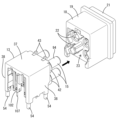
- FIG. 1 is an exploded perspective view of a shield connector according to Embodiment 1 of the present disclosure
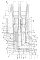
- FIG. 2 is a side sectional view showing a mated state between the shield connector and the mating connector.
- FIG. 3 is an enlarged cross-sectional plan view showing a state in which the press-fitting blade of the outer conductor tube is engaged with the inner peripheral surface of the through hole of the outer shell.
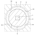
- FIG. 4 is an enlarged cross-sectional view showing a state in which the holding protrusion of the outer conductor tube contacts the inner peripheral surface of the through hole of the outer shell.
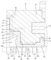
- FIG. 5 is an enlarged cross-sectional view showing a state in which the housing-side holding projection of the housing is in contact with the outer peripheral surface of the outer conductor tube.
- FIG. 6 is an enlarged transverse cross-sectional view showing a state in which the contact projection of the projection of the outer conductor tube contacts the restricting portion.
- 7 is a cross-sectional view taken along the line AA of FIG. 6.
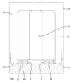
- FIG. 8 is a side sectional view showing an enlarged internal structure of the outer conductor at the rear portion of the shield connector.
- FIG. 9 is a rear view of the shield connector.
- FIG. 10 is an enlarged rear view showing a state of solder joint between the mounting portion and the circuit board that can be confirmed through the recessed portion.
- FIG. 11 is a perspective view for explaining the process of assembling the outer shell to the housing.
- FIG. 12 is a perspective view for explaining the process of assembling the substrate-side outer shell to the outer shell.
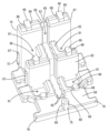
- FIG. 13 is a perspective view of a shield connector.
- FIG. 14 is a front view of the housing.
- FIG. 15 is a rear view of the housing.
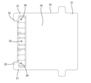
- FIG. 16 is a bottom view of the housing;
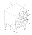
- FIG. 17 is a perspective view of an outer shell.
- FIG. 18 is a rear view of the outer shell.
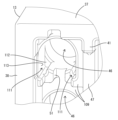
- FIG. 19 is a perspective view showing an enlarged through-hole of the outer shell.
- FIG. 20 is a perspective view of the board-side outer shell.
- FIG. 21 is a perspective view of the substrate-side outer shell viewed from another angle.
- FIG. 22 is a perspective view of an outer conductor tube.
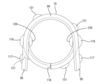
- FIG. 23 is a rear view of the outer conductor tube.
- the shielded connector of the present disclosure provides: (1) An inner conductor, an outer conductor surrounding the inner conductor, and a dielectric disposed between the inner conductor and the outer conductor, wherein the outer conductor is a cylindrical outer conductor tube and an outer shell body, the outer shell body having a through hole in which the outer conductor tube is arranged, the outer conductor tube protruding radially outward and extending through the through hole of the outer shell body.
- the holding protrusions are arranged at both ends in the radial direction of the outer conductor tube, and the holding protrusions are arranged at positions in the outer conductor tube that are displaced in the circumferential direction from the press-fitting blades when the outer conductor tube is viewed from the axial direction. ing.
- the term "out of alignment” refers to a state in which the axial centers of the outer conductors do not coincide with each other at the time of connection between the outer conductor and the mating outer conductor, resulting in misalignment.
- the holding protrusion is arranged at a position shifted in the axial direction from the press-fitting blade in the outer conductor tube. According to the above configuration, it is possible to prevent the outer conductor tube from being inclined from the axial direction with respect to the outer shell.
- a plurality of the holding protrusions be arranged in the outer conductor tube at intervals in the circumferential direction.
- the above configuration can highly reliably suppress the collapse of the alignment of the outer conductor tube.
- the holding protrusions are arranged at upper, lower, left, and right portions on the outer peripheral surface of the outer conductor tube when viewed from the axial direction.
- the above configuration can omnidirectionally suppress the collapse of the alignment of the outer conductor tube from four directions of up, down, left, and right.
- a synthetic resin housing connected to the outer conductor is provided, and the housing includes an insertion hole in which an end portion of the outer conductor tube passing through the through hole is arranged, and an inner peripheral surface of the insertion hole. and a housing-side holding protrusion that protrudes from and contacts the outer peripheral surface of the end of the outer conductor tube, and the housing-side holding protrusions are arranged in plurality in the housing at intervals in the circumferential direction. It's good to be
- the housing-side holding protrusion can contact the outer peripheral surface of the outer conductor tube in a compressed or crushed state, so it is possible to increase the dimensional tolerance between the housing and the outer conductor.
- a plurality of housing-side holding projections arranged at intervals in the circumferential direction come into contact with the outer peripheral surface of the end of the outer conductor tube, thereby correcting the misalignment of the axial center of the end of the outer conductor tube. can be done.
- the shield connector 10 is a board shield connector installed on a circuit board 200 .
- the shield connector 10 includes inner conductors 11 and 12; outer conductors 13, 14 and 15 surrounding the inner conductors 11 and 12; , 14, 15 and a housing 18 to which the outer conductors 13, 14, 15 are connected.
- the outer conductors 13, 14, 15 and the inner conductors 11, 12 are conductive members such as metal.
- Dielectrics 16 and 17 and housing 18 are insulating members such as synthetic resin.
- the housing 18 is fitted to the mating connector 300 .
- the front side Regarding the front-rear direction, the side facing the mating connector 300 when the housing 18 is mated is defined as the front side.
- the side on which the shield connector 10 is installed with respect to the circuit board 200 is the upper side.
- the upper side of FIGS. 1 and 2 is the upper side. In FIG. 2, the upper side is indicated by the code "U" and the front side is indicated by the code "F".
- the vertical direction is synonymous with the height direction
- the front-rear direction is synonymous with the axial direction
- the left-right direction is a direction intersecting the front-rear direction and the up-down direction, and is synonymous with the width direction.
- the housing 18 has a rectangular outer shape as a whole, and has a housing body 19 and a hood 21 projecting forward from the housing body 19 .
- the housing body 19 has a plurality of (four in the first embodiment) insertion holes 22 penetrating in the front-rear direction.
- Each of the insertion holes 22 has a circular cross section and is arranged side by side in the width direction.
- a fitting recess 23 is formed which is recessed leaving the central portion of the housing body 19. As shown in FIG. A plurality of recessed ribs 24 are formed on the inner peripheral surface of the fitting recess 23 .
- the housing body 19 has a plurality of housing-side holding protrusions 108 on the inner peripheral surface of each insertion hole 22 .
- Each housing-side holding protrusion 108 has an arcuate cross section and is formed to extend over the entire length of each insertion hole 22 .
- the housing-side holding protrusions 108 are provided on the inner peripheral surface of each insertion hole 22 at four locations, upper right, lower right, upper left, and lower left, as seen from the axial direction, at equal intervals in the circumferential direction. ing.
- each housing-side holding protrusion 108 contacts the outer peripheral surface of the outer conductor tube 15 .
- the upper end of the housing body 19 is formed with a die-cut recess 26 .
- the die-cut recess 26 is formed so as to be opened rearward when a die (not shown) for molding the housing lock portion 36, which will be described later, is pulled out.
- a pair of fitting holes 27 are formed on both left and right sides of the die-cut recess 26 at the upper end of the housing body 19 . As shown in FIG. 2 , the fitting hole 27 extends through the upper end of the housing body 19 in the front-rear direction and communicates with the inside of the hood 21 .
- the rear end of the housing body 19 is formed with a pair of first locking projections 28 protruding into the respective fitting holes 27 .
- Each first locking projection 28 faces the rear surface of the housing body 19 and protrudes toward the fitting recess 23 .
- a first connecting projection 43 of the outer shell 13 comes into contact with the front surface of the first locking projection 28 and is locked.
- the housing body 19 has a pair of housing side portions 31 that partition the left and right sides of the fitting recess 23.
- a pair of second locking projections 32 are formed on the inner surface (surface facing each other) of the lower end side of each housing side portion 31 so as to protrude toward the fitting recess 23 side.
- each fitting groove 34 is open vertically and inwardly in the width direction (center side in the width direction of the housing 18 ) between each second locking projection 32 and the inner surface of the fitting recess 23 .
- a second connecting protrusion 76 of the board-side outer shell 14, which will be described later, is inserted into the fitting groove 34 of the housing body 19 from below.
- a second connecting protrusion 76 of the substrate-side outer shell 14, which will be described later, comes into contact with the front surface of the second locking protrusion 32 in a pressed state.
- the hood 21 has a rectangular tubular shape. As shown in FIG. 2 , the mating connector 300 is inserted and fitted into the hood 21 . As shown in FIG. 14, the hood 21 is formed with a pair of protruding pieces 35 protruding forward from the front surface of the housing body 19 . Each projecting piece 35 is inserted into a space 301 (see FIG. 1) formed in the mating connector 300 . A housing lock portion 36 for locking the mating connector 300 is formed on the upper wall of the hood 21 . By locking the mating connector 300 with the housing lock portion 36, the housing 18 and the mating connector 300 are held in a fitted state.
- the outer conductor is composed of an outer shell 13, a board-side outer shell 14, and a plurality of outer conductor tubes 15, as shown in FIG.
- the outer shell 13 and the substrate-side outer shell 14 are die-cast conductive rigid bodies such as zinc alloy and aluminum alloy derived from casting, and are molded from the same material.
- the outer shell 13 and the board-side outer shell 14 are assembled together to form one housing.
- the outer conductor tube 15 is a press-formed body formed by bending a metal plate made of a material such as brass having higher hardness than the outer shell 13 and the board-side outer shell 14 .
- the outer shell 13 has an upper portion 37 that is rectangular in plan view and a pair of side portions 38 projecting downward from both left and right ends of the upper portion 37 .
- a fitting receiving portion 39 is formed between the upper portion 37 and each side portion 38 .
- the fitting receiving portion 39 is opened downward and rearward in the outer shell 13 .
- the outer shell body 13 has a mounting portion 41 that is built up on the fitting receiving portion 39 side and connected to the upper portion 37 and the side portions 38 respectively.
- the mounting portion 41 closes the front surface of the outer shell 13 .
- a plurality of cylindrical portions 42 are formed on the front surface of the outer shell 13 so as to protrude.
- a pair of upper and lower cylindrical portions 42 are arranged side by side in the width direction on the front side of the outer shell 13 .
- Each cylindrical portion 42 is connected to each other vertically and horizontally, and has a shape that can fit into the fitting recess 23 .
- the outer shell body 13 has a pair of first connecting protrusions 43 that protrude upward from each cylindrical portion 42 on the upper side.
- the upper end side of each first connecting protrusion 43 protrudes upward from the upper portion 37 .
- a press-fit recess 45 is formed at the lower end of the front surface of the outer shell 13 .
- the press-fit recesses 45 are arranged between the lower cylindrical portions 42 .
- the press-fit recess 45 is defined by the lower cylindrical portions 42 and a connecting portion that connects the lower cylindrical portions 42 in the width direction, and is open forward and downward.
- the rear side of the press-fit recess 45 is closed by the front side of the outer shell 13 .
- the press-fit recess 45 has a dovetail groove shape that gradually increases in width from the lower end on the opening side toward the upper end on the inner side.
- a press-fit protrusion 75 of the substrate-side outer shell 14, which will be described later, is press-fit into the press-fit recess 45 (see FIG. 8).
- the mounting portion 41 has a plurality of through holes 46 penetrating in the front-rear direction.
- Each through hole 46 has a circular cross-section, and as shown in FIG.
- the cylindrical portions 42 are fitted into the fitting recesses 23 of the housing 18, and as shown in FIG. It communicates with the insertion hole 22 in the front-rear direction.
- an engaging protrusion 47 that protrudes toward the fitting receiving portion 39 is formed in the center portion of the outer shell 13 in the width direction.
- the engaging protrusions 47 have a plate-like shape along the vertical direction in the mounting portion 41 and are arranged between the through holes 46 adjacent in the width direction.
- the lower end of the engaging projection 47 has a stepped shape (see FIG. 8).
- Each upper through-hole 46 in the mounting portion 41 corresponds to the stepped shape of the lower end of the engaging protrusion 47 and is formed longer rearward than each lower through-hole 46 (see FIG. 2).
- each through-hole 46 opens to an end face 109 arranged facing rearward in the fitting receiving portion 39 .
- the end face 109 where the upper through-holes 46 open is located behind the end face 109 where the lower through-holes 46 open.
- an end surface 109 of the mounting portion 41 is formed with a pair of grooves 111 cut forward from the lower left and right side edges of the rear opening edge of the through hole 46 .
- groove portions 51 which will be described later, are arranged between the cut grooves 111.
- the outer shell 13 has a stopper portion 112 that closes the front end of each cut groove 111 in each through hole 46 .
- the stopper portion 112 is arranged on the front surface of each cut groove 111 along the vertical direction like the end surface 109 .
- the outer shell 13 has restricting portions 113 that block the widthwise outer sides of the respective cut grooves 111 in the respective through holes 46 .
- the restricting portion 113 is a part of the inner surface of the side portion 38 , is arranged along the front-rear direction, and has a front end that intersects the stopper portion 112 .
- the stopper portion 112 is capable of stopping a projecting portion 95 (described later) of the outer conductor tube 15 (see FIG. 7), and the restricting portion 113 is capable of restricting the rotation of the outer conductor tube 15 in the through hole 46. (see Figure 6).
- a plurality of grooves 51 are formed in the outer shell 13 as shown in FIG.
- Each groove portion 51 is formed by cutting out the lower portion (including the stepped portion) of the peripheral wall surrounding each through hole 46 in the mounting portion 41 , and is recessed in the inner surface of the rear end portion of the upper portion 37 . ing.
- Each groove portion 51 is arranged for each through hole 46 and is open downward and rearward on the fitting receiving portion 39 side.
- Each groove 51 in the lower part of the peripheral wall opens to the end face 109 .
- each leg portion 54 is formed at the front and rear end portions of the lower end of each side portion 38 so as to protrude downward.
- Each leg portion 54 is arranged corresponding to the lower end four corners of the outer shell 13 .
- each leg 54 is positioned and inserted into the fixing hole 201 of the circuit board 200 .
- each recessed portion 56 is open inward in the width direction (the side where the side portions 38 face each other) and rearward. As shown in FIG. 9 , each projection 72 of the board-side outer shell 14 , which will be described later, is fitted into each recess 56 .
- the board-side outer shell 14 is assembled to the outer shell 13 from below.
- the board-side outer shell 14 includes a bottom portion 59 that is rectangular in bottom view, a back portion 61 that rises from the rear end of the bottom portion 59, and a rising portion 62 that rises from a position near the rear end of the bottom portion 59. and a partition portion 63 connecting the back portion 61 and the rising portion 62 at the center portion in the width direction of the bottom portion 59 .
- the back portion 61 , the rising portion 62 and the partition portion 63 are configured as fitting portions that can be fitted to the fitting receiving portions 39 of the outer shell 13 .
- the back portion 61 and the rising portion 62 form a rectangular vertical wall when viewed from the rear. As shown in FIG. 9 , the back portion 61 closes the rear surface of the outer shell 13 . As shown in FIGS. 20 and 21, the projection dimension of the rising portion 62 is smaller than the projection dimension of the back portion 61 .
- the height difference between the upper end surface of the rising portion 62 and the upper end surface of the back portion 61 corresponds to the height difference of the stepped shape of the mounting portion 41 .
- the upper end surface of the rising portion 62 and the upper end surface of the partition portion 63 are continuous at the same height.
- a groove 52 is formed in the central portion of the substrate-side outer shell 14 in the width direction.
- the groove portion 52 is continuously recessed in a stepped manner on the upper surface and the front surface of each of the back portion 61 , the partition portion 63 , the rising portion 62 and the bottom portion 59 .
- the groove portion 52 has a plurality of vertically extending contact ribs 65 on both side surfaces facing each other in the width direction.
- Each contact rib 65 has an arcuate cross section.
- a large number of contact ribs 65 are formed at intervals in the front-rear direction on both side surfaces of the groove 52 corresponding to the back portion 61, the partition portion 63, the rising portion 62 and the bottom portion 59, respectively.
- a pair of engaging protrusions 49 are formed on the top surface of each of the back portion 61 , the rising portion 62 and the bottom portion 59 on both the left and right sides with the groove portion 52 interposed therebetween.
- Contact ribs 66 extending in the vertical direction are also formed on both side surfaces of each engaging protrusion 49 .
- each engaging protrusion 49 of the board-side outer shell 14 is fitted into each groove 51 of the outer shell 13.
- the contact ribs 65 and 66 of the board-side outer shell 14 contact the outer surface of the engaging protrusion 47 and the inner surface of each groove 51 of the outer shell 13 .
- contact ribs 67 extending in the vertical direction are also formed on both side surfaces of the back portion 61 and the upright portion 62 . This contact rib 67 contacts the inner surface of each side 38 of the shell 13 (see FIG. 9).
- the substrate-side outer shell 14 has a pair of protrusions 72 at the lower rear end portions of both side surfaces.
- Each projecting portion 72 has an arc-shaped cross-section extending in the front-rear direction on both side surfaces of the bottom portion 59 .
- the front end sides of the protrusions 72 are integrally connected to the lower ends of the contact ribs 67 formed on both side surfaces of the back portion 61 .
- a press-fit protrusion 75 is formed at the center of the upper surface of the front end portion of the bottom portion 59 in the width direction.
- the press-fit projection 75 is columnar and formed with a constant cross-sectional shape in the vertical direction except for the upper end.
- a pair of vertically extending contact ribs 68 are also formed on both side surfaces of the press-fit projection 75 . Each contact rib 68 contacts the inner surface of the press-fit recess 45 .
- the board-side outer shell 14 has a pair of second connecting protrusions 76 that protrude outward in the width direction from the front ends of both side surfaces of the bottom portion 59 .
- a pressing rib 78 having an arcuate cross-section extending in the vertical direction is formed on the rear surface of each second connecting projection 76 .
- the pressing rib 78 of the second connecting protrusion 76 contacts the front surface of the second locking protrusion 32 in a pressing state when the second connecting protrusion 76 is fitted in the fitting groove 34 of the housing 18 (Fig. 13).
- a plurality of openings 81 are formed in the board-side outer shell 14 .
- Each of the openings 81 has a rectangular cross section, and is arranged on both the left and right sides of the substrate-side outer shell 14 with the groove 52 interposed therebetween, and on the front and rear positions.
- Each opening 81 on the front side is located in front of the rising portion 62 and behind the engaging projection 49 formed on the bottom portion 59, and penetrates through the bottom portion 59 to form a bottom surface 92 (a surface facing downward, which is shown in FIG. 12).
- Each opening 81 on the rear side is partitioned by a back portion 61 , a raised portion 62 and a partition portion 63 , and likewise penetrates through the bottom portion 59 to open to the bottom surface 92 .
- the partition part 63 partitions the rear openings 81 adjacent in the width direction.
- Dielectrics 16 and 17 are fitted into each opening 81 as shown in FIG.
- the inner conductors 11 , 12 attached to the dielectrics 16 , 17 cause the board connecting portion 107 , which will be described later, to protrude downward from the bottom surface 92 of the bottom portion 59 through the opening 81 .
- the board connection portion 107 is inserted into a connection hole 202 formed in the circuit board 200 and electrically connected to a conductive portion (not shown).
- a plurality of mounting parts 84 to 87 are formed on the bottom surface 92 of the bottom part 59 so as to surround the periphery of each opening 81 .
- Each of the mounting portions 84 to 87 protrudes slightly downward from the bottom surface 92 of the bottom portion 59 .
- the lower end surfaces of the mounting portions 84 to 87 are flat and electrically connected to the conductive portion for grounding of the circuit board 200 by soldering.
- the mounting portions include a front mounting portion 84 extending in the left-right direction on the front side of each front opening 81 , a side mounting portion 85 extending in the front-rear direction on both left and right sides of each opening 81 , and a front mounting portion 85 extending in the front-rear direction. and a shared mounting portion 86 extending in the left-right direction between the opening 81 and the opening 81 on the rear side.
- Complementary mounting portions 87 as mounting portions are also formed on both left and right sides of the recessed portion 91 to be described later.
- a retraction recess 88 is provided at the rear end of the bottom surface 92 of the bottom portion 59 .
- the rear end of the retraction recess 88 opens to a rear surface 93 that intersects the bottom surface 92 of the board-side outer shell 14 .
- the retraction recess 88 has a rectangular cross section, communicates with the opening 81 at the front, opens rearward and downward, and is closed at the top by the back portion 61 .
- the retraction recess 88 is arranged above surface wiring (not shown) of the circuit board 200 .
- the substrate-side outer shell 14 is prevented from being electrically connected to the surface layer wiring by the recess 88 .
- the complementary mounting portion 87 corresponds to each of the retraction recesses 88 and is formed to extend in the front-rear direction along the inner side edge of each side edge of each retraction recess 88 located at the center side in the width direction of the bottom portion 59 . It is
- a recessed portion 91 is provided in the center of the width direction of the rear surface 93 of the board-side outer shell 14 .
- recessed portion 91 is formed to extend vertically from bottom portion 59 to back portion 61 on back surface 93 of board-side outer shell 14 .
- the recessed portion 91 is recessed across the bottom surface 92 and the back surface 93 of the board-side outer shell 14 and is open rearward and downward.
- the concave portion 91 penetrates the back portion 61 and is partitioned inside the partition portion 63 . That is, the concave portion 91 is formed within the thickness range of the partition portion 63 .
- the inner depth surface 126 and the inner upper surface 127 of the recessed portion 91 are arranged in parallel with the groove portion 52 behind and below the groove portion 52 in a back-to-back manner.
- a portion of the partition portion 63 between the recessed portion 91 and the groove portion 52 (see symbol a in FIG. 8) is formed with a uniform thickness or a nearly uniform thickness from the back portion 61 to the bottom portion 59 .
- the thickness of the partition portion 63 is reduced at the portion corresponding to the recessed portion 91 . As shown in FIG.
- the complementary mounting portion 87 is arranged on the bottom surface 92 of the bottom portion 59 so as to be sandwiched in the width direction between the retraction recess 88 and the recess 91 .
- the side mounting portion 85 positioned on the inner side in the width direction (center side in the width direction) of the bottom surface 92 of the board-side outer shell 14 is located on the board side as shown in FIGS. It is arranged so as to be visible through the recessed portion 91 when the outer shell 14 is viewed from the rear.
- the outer conductor tube 15 is integrally formed by bending a conductive metal plate or the like, and is thinner than each of the outer shell 13 and the board-side outer shell 14 .
- the outer conductor tube 15 has a cylindrical connecting portion 94 extending in the front-rear direction, and a pair of projecting portions 95 projecting downward from both left and right sides of the rear end portion of the cylindrical connecting portion 94 .
- the cylindrical connecting portion 94 is formed by bending a plate material into a circular shape, and has a butting edge 116 at the lower end where both ends in the circumferential direction are butted against each other, as shown in FIG. 23 .
- Each protruding portion 95 has a tapered shape that spreads downward from the left and right ends of the upper half of the rear end portion of the cylindrical connecting portion 94 before the outer conductor tube 15 is inserted into the through hole 46 of the outer shell 13 . None. Moreover, the projecting portion 95 has a rectangular shape in a side view. An embossed contact protrusion 117 that bulges outward is formed at a portion near the lower end of each protrusion 95 . The contact protrusion 117 has an arcuate cross section.
- a press-fit blade 118 is formed in the front-rear intermediate portion of the cylindrical connection portion 94 .
- the press-fitting blades 118 form a pair at both the left and right ends (both ends in the radial direction) of the cylindrical connecting portion 94, and bulge outward in front of the slit 119 along the vertical direction (also the circumferential direction of the cylindrical connecting portion 94). It is formed in a shape that Specifically, as shown in FIG. 22, the press-fitting blade 118 has an arcuate cross-section, and has a triangular shape whose vertical dimension decreases forward in a side view. As shown in FIG. 3, each press-fitting blade 118 is press-fitted into the inner peripheral surface of the through hole 46 of the outer shell 13 and locked.
- inner protrusions 120 are formed in the front and rear intermediate portions of the cylindrical connection portion 94 .
- each inner projection 120 forms a pair at both the left and right ends of the cylindrical connecting portion 94, and is behind the slit 119 along the vertical direction (also the circumferential direction of the cylindrical connecting portion 94). It is formed in a shape that bulges inward.
- Each inner projection 120 is anchored to the outer surface of dielectrics 16, 17 located within tubular connecting portion 94 (see FIG. 3).
- a plurality of holding protrusions 121 are formed on the cylindrical connecting portion 94 at a portion behind the press-fitting blade 118 and forward of the projecting portion 95 .
- Each holding protrusion 121 has an embossed shape that protrudes outward from the cylindrical connecting portion 94 and extends in the front-rear direction with a constant cross-sectional shape (arc shape).
- each holding protrusion 121 is protruded from the outer peripheral surface of the cylindrical connecting portion 94 at regular intervals in the circumferential direction.
- the press-fitting blade 118 protrudes from the outer peripheral surface of the cylindrical connecting portion 94 larger than the holding protrusion 121 .
- each holding protrusion 121 is arranged to be displaced from each press-fitting blade 118 in the circumferential direction. .
- each of the holding projections 121 is arranged at four locations, upper right, lower right, upper left, and lower left, which are upper, lower, left, and right portions when the cylindrical connection portion 94 is viewed from the front. .
- the outer conductor tube 15 is inserted into the through hole 46 of the outer shell 13 from behind.
- a plurality of outer conductor tubes 15, four in the case of the first embodiment, are provided corresponding to each through-hole 46, and as shown in FIG. 1, they are formed in the same shape.
- each projecting portion 95 is abutted against the stopper portion 112 (see FIG. 7)
- each press-fitting blade 118 is locked to the inner peripheral surface of the through hole 46 (see FIG. 3), and further
- each contact protrusion 117 comes into contact with the restricting portion 113 in a state where each protrusion 95 is elastically deformed (see FIG. 6)
- the front end portion of the cylindrical connecting portion 94 of the outer conductor tube 15 is arranged to protrude into the hood 21 from the cylindrical portion 42 of the outer shell 13 in the shield connector 10 (see FIG. 2).
- the dielectrics 16 and 17 have a cylindrical body portion 101 extending in the front-rear direction and a lead portion 102 projecting downward from the rear end portion of the body portion 101. shaped like a letter. Later-described horizontal portions 104 of the inner conductors 11 and 12 are inserted into the body portion 101 . A guide groove 103 extending in the vertical direction is formed on the rear surface of the lead-out portion 102 . The guide groove 103 is open rearward. Later-described extending portions 105 of the inner conductors 11 and 12 are fitted into the guide grooves 103 from behind (see FIGS. 2 and 7).
- the main bodies 101 of the dielectrics 16 and 17 are arranged in the through holes 46 of the outer shell 13 while being inserted into the tubular connecting portion 94 of the outer conductor tube 15 .
- Lead-out portions 102 of dielectrics 16 and 17 are inserted into openings 81 of board-side outer shell 14 .
- the dielectric is composed of two types of long and short dielectrics 16 and 17, as shown in FIG.
- the elongated dielectric 16 is connected to the outer conductors 13 and 14 with the body portion 101 disposed in the upper through hole 46 and the lead portion 102 inserted into the rear opening 81 .
- the short dielectric 17 is held by the outer conductors 13 , 14 , 15 with the body portion 101 placed in the lower through hole 46 and the lead portion 102 inserted into the front opening 81 .
- the inner conductors 11 and 12 are pin-shaped terminals and have a horizontal portion 104 extending in the front-rear direction and an extension portion 105 extending downward from the rear end portion of the horizontal portion 104. , and is formed in an L shape when viewed from the side.
- the horizontal portion 104 has a mating connection portion 106 that protrudes forward from the main body portion 101 while being inserted into the main body portion 101 of the dielectrics 16 and 17 .
- the mating connection portion 106 protrudes into the hood 21 and is electrically connected to the mating inner conductor 303 when the housing 18 and the mating connector 300 are fitted together.
- the extending portion 105 has a substrate connecting portion 107 that protrudes downward from the lead portion 102 while being inserted into the guide groove 103 of the lead portion 102 of the dielectrics 16 and 17 .
- the board connection portion 107 is formed to have a smaller diameter than the upper portion of the extension portion 105 .
- the inner conductor is composed of two types of inner conductors 11 and 12, long and short, as shown in FIG.
- An elongated inner conductor 11 is held by an elongated dielectric 16 .
- a short inner conductor 12 is held in a short dielectric 17 .
- each of the inner conductors 11 and 12 is inserted into and held in the body portion 101 of the corresponding dielectric 16 and 17 from behind.
- the extending portions 105 of the inner conductors 11 and 12 are arranged to be exposed on the rear surface side of the lead portion 102 while being inserted into the guide grooves 103 .
- the body portions 101 of the dielectrics 16 and 17 are inserted into the cylindrical connection portions 94 of the corresponding outer conductor tubes 15 from behind and held.
- the cylindrical connecting portion 94 of each outer conductor tube 15 is inserted into the corresponding through hole 46 of the outer shell 13 from behind and held.
- each projecting portion 95 enters each cut groove 111 from the rear, and the contact projecting portion 117 of each projecting portion 95 slides along the restricting portion 113 .
- each protruding portion 95 is elastically deformed inward in the width direction (center side in the width direction of the outer conductor tube 15) with the connection portion with the tubular connection portion 94 as a fulcrum.
- each projecting portion 95 When the cylindrical connecting portion 94 is properly inserted into the through hole 46 of the outer shell 13, the front end (plate thickness portion) of each projecting portion 95 abuts against the stopper portion 112 of the outer shell 13 (see FIG. 7). , further insertion of the outer conductor tube 15 is restricted. Each projecting portion 95 firmly contacts each contact projecting portion 117 with the restricting portion 113 while being elastically deformed (see FIG. 6). The outer conductor tube 15 is restrained from rattling by the outer shell 13 by the locking action of the projecting portion 95 on the outer shell 13 and the holding action of the press-fitting blade 118 and each holding protrusion 121, which will be described later. can be assembled.
- the outer conductor tube 15 is assembled to the outer shell 13 from the rear, so that the structure for preventing the outer conductor tube 15 from coming off from the front by the stopper portion 112 can be easily formed.
- the press-fitting blades 118 of the outer conductor tube 15 are positioned on the left and right sides of the inner peripheral surface of the through hole 46 of the outer shell 13 . It is locked so as to bite into both ends in a press-fitted state (compressed or crushed state) (see FIG. 3). Further, each holding protrusion 121 of the outer conductor tube 15 firmly contacts the upper, lower, left, and right portions of the inner peripheral surface of the through hole 46 of the outer shell 13 behind the locking position of each press-fitting blade 118. (See Figure 4).
- the front end portion of the cylindrical connecting portion 94 is arranged so as to protrude forward from the cylindrical portion 42 of the outer shell 13 . If the holding protrusions 121 were not formed on the tubular connection portion 94, when an external force acts on the front end portion of the tubular connection portion 94 from above or below, the tubular connection portion 94 would be pushed in the direction of the external force. There is a concern that the axial center of the tubular connection portion 94 may be shifted due to the pressure on the cylindrical connection portion 94 .
- a plurality of holding projections 121 are formed on the cylindrical connecting portion 94 separately from the press-fitting blades 118, and each holding projection 121 is formed on each of the upper, lower, left, and right portions of the cylindrical connecting portion 94. They are spaced apart in the circumferential direction. Since each holding projection 121 is held in contact with the inner peripheral surface of the through hole 46 of the outer shell 13, it can resist external force from above or below, and the axial center of the cylindrical connecting portion 94 is held. can be prevented from slipping.
- the outer shell 13 is connected to the housing 18 from behind (see FIG. 11).
- the first connecting protrusion 43 climbs over the first locking protrusion 28 and fits into the fitting hole 27 .
- the cylindrical portion 42 contacts the inner surface of the fitting recess 23 to stop the connecting operation of the outer shell 13, and the rear surface of the first connecting projection 43 and the first engagement.
- the front surfaces of the stop projections 28 contact each other (see FIG. 2).
- the front end of the cylindrical connecting portion 94 is inserted into the insertion hole 22 of the housing 18 from behind.
- Each housing-side holding protrusion 108 contacts the outer peripheral surface of the front portion of the cylindrical connecting portion 94 in a compressed or crushed state inside the insertion hole 22 (see FIG. 5).
- Each housing-side holding protrusion 108 contacts the outer peripheral surface of the cylindrical connecting portion 94 from the upper, lower, left, and right sides.
- the cylindrical connecting portion 94 is held by the outer shell 13 by the press-fitting blades 118 and the holding projections 121, and is also located on the opposite side (front side) of the holding projections 121 across the press-fitting blades 118. ) are held in the housing 18 by housing-side holding projections 108 located at .
- Embodiment 1 it is possible to more reliably prevent the axial center of the cylindrical connecting portion 94 from being deviated. As a result, it is possible to achieve a state in which the axial center of the cylindrical connecting portion 94 is aligned with the axial center of the mating outer conductor 311 (see FIG. 2).
- the board-side outer shell 14 is assembled to the outer shell 13 from below (see FIG. 12).
- the protrusion 72 interferes with the side portion 38, and the side portion 38 elastically deforms outward in the width direction with the upper portion 37 as a fulcrum.
- the engaging protrusion 47 of the shell 13 comes into contact with the bottom surface of the groove 52 of the board-side shell 14, and the assembly operation of the board-side shell 14 stops.
- a restoring force acts on the side portion 38, and the projection 72 is fitted into the recess 56 (see FIG. 9).
- the protrusion 72 can contact the inner surface of the recess 56 and maintain the contact state.
- the fitted state of the recessed portion 56 and the projecting portion 72 can be visually recognized in a rear view.
- the press-fitting protrusion 75 is fitted into the press-fitting recess 45 from below, and each contact rib 68 of the press-fitting protrusion 75 is compressed or crushed by the inner surface of the press-fitting recess 45 on the opening side. contact with the state. Therefore, the substrate-side outer shell 14 is stably held in a state in which tilting in the front-rear direction is restricted with respect to the outer shell 13 .
- the second connecting protrusion 76 is fitted into the fitting groove 34 of the housing 18 (see FIG. 13), and the pressing rib 78 of the second connecting protrusion 76 is pushed to the second position.
- the second connecting projection 76 contacts the front surface of the second locking projection 32 and is retained in the housing 18 in a retaining state.
- the back portion 61, the rising portion 62 and the partitioning portion 63 are fitted into the fitting receiving portions 39 of the shell 13, and the engaging projections of the board-side shell 14 are fitted.
- the portions 49 are fitted into the respective grooves 51 of the outer shell 13 (see FIG. 9), and the engaging protrusions 47 of the outer shell 13 are fitted into the grooves 52 of the board-side outer shell 14 .
- Each of the contact ribs 65 to 68 of the substrate-side outer shell 14 contacts corresponding surfaces such as the inner surface of each groove 51 and the outer surface of the engaging projection 47 of the outer shell 13 in a compressed or crushed state.
- Each of the contact ribs 65-68 is in contact with the corresponding surface of the outer shell 13 along the vertical direction. Therefore, even if a vertical vibration force is applied to the outer shell 13 and the substrate-side outer shell 14, the contact state of the contact ribs 65 to 68 can be maintained.
- a large number of contact ribs 65 to 68 are formed on the inner surface of each groove 52 and the outer surface of each engaging projection 49 of the substrate-side outer shell 14.
- the engaging projections 49 are fitted into the grooves 51 of the outer shell 13, and the engaging projections 47 of the outer shell 13 are fitted into the grooves 52 of the board-side outer shell 14. 68 can reliably contact the corresponding surface of the outer shell 13 .
- the outer shell 13 and the substrate-side outer shell 14 are assembled, as shown in FIG. It is arranged to cover the short inner conductor 12 from behind. Also, the back portion 61 is arranged so as to cover the outer conductor tube 15, the long dielectric 17 and the long inner conductor 11 arranged in the upper through-hole 46 from behind. The lead portions 102 of the inner conductors 11 and 12 are surrounded by the outer conductors 13 , 14 and 15 except for the substrate connecting portion 107 . Assembly of the shield connector 10 is thus completed.
- the shield connector 10 is installed on the surface of the circuit board 200 (see FIGS. 2 and 8 to 10).
- the board connection portions 107 of the inner conductors 11 and 12 are inserted into the connection holes 202 of the circuit board 200, the legs 54 of the outer shell 13 are inserted into the fixing holes 201 of the circuit board 200, and the mounting portions 84 are inserted. 87 are placed on the lands of the conductive portion of the circuit board 200 .
- reflow soldering is performed so that the board connection portions 107 of the inner conductors 11 and 12 are soldered to the signal conductive portions of the connection holes 202 of the circuit board 200 .
- Each leg portion 54 is soldered to a fixing hole 201, and each mounting portion 84 to 87 is soldered to a conductive portion for grounding.
- Each of the inner conductors 11 and 12 is surrounded by a plurality of mounting portions 84 to 87 on the bottom surface 92 of the substrate-side outer shell 14. Therefore, crosstalk between the inner conductors 11 and 12 adjacent in the width direction and the front-rear direction is suppressed.
- the board-side outer shell 14 is formed with a retracting recess 88 that is recessed away from the surface wiring of the circuit board 200, the board-side outer shell 14 can be prevented from being electromagnetically coupled to the surface wiring. can be done.
- the board-side outer shell 14 is provided with the concave portion 91 from the rear surface 93 to the bottom surface 92 of the back portion 61, and the thickness of the partition portion 63 is reduced, so that the thermal conduction resistance is reduced.
- the heat transfer to the mounting portions 84 to 87 is excellent.
- the recessed portion 91 extends to the vicinity of the side mounting portion 85 on the bottom surface 92 of the substrate-side outer shell 14, it is possible to effectively prevent the side mounting portion 85 from being unsoldered. .
- the side mounting portion 85 is soldered to the conductive portion of the circuit board 200 (see the solder fillet indicated by symbol b in FIG. 10). It can be confirmed through an opening in the back surface 93 .
- the outer shell is configured separately from the substrate-side outer shell.
- the outer shell may be formed integrally with the substrate-side outer shell.
- the projecting portion of the outer conductor tube has a contact projecting portion.
- the protrusions may not have contact protrusions.
- the side surface (plate surface) of the projecting portion can be brought into contact with the restricting portion of the outer shell.
- the housing is provided with the housing-side holding projection.
- the housing may not be formed with the housing-side holding protrusion. In this case, it is preferable to form a holding projection corresponding to the housing-side holding projection on the outer peripheral surface of the outer conductor tube.
- Second second Locking protrusion 34 Fitting groove 35 Protruding piece 36 Housing locking part 37 Upper part 38 Side part 39 Fitting receiving part 41 Mounting part 42 Cylindrical part 43 First connecting protrusion 45 Press-fit recess 46... Through hole 47... Engagement protrusion (engagement protrusion) of outer shell 49 ... Engagement protrusion (engagement protrusion) of board-side outer shell body 51... Grooves (grooves) of outer shell 52: Groove (groove) of substrate-side outer shell 54... Leg part 56... Recess part 59... Bottom part 61... Back part (fitting part) 62... Rising portion (fitting portion) 63...
Landscapes
- Details Of Connecting Devices For Male And Female Coupling (AREA)
- Coupling Device And Connection With Printed Circuit (AREA)
Abstract
Description
最初に本開示の実施態様を列記して説明する。
本開示のシールドコネクタは、
(1)内導体と、前記内導体を包囲する外導体と、前記内導体と前記外導体との間に配置される誘電体と、を備え、前記外導体は、筒状の外導体チューブと、外殻体と、を有し、前記外殻体は、前記外導体チューブが配置される通し孔を有し、前記外導体チューブは、径方向外側に突出して前記外殻体の前記通し孔の内周面に係止される圧入刃と、前記径方向外側に突出して前記外殻体の前記通し孔の内周面に接触する保持突部と、を有し、前記圧入刃は、前記外導体チューブの径方向両端部に配置され、前記保持突部は、前記外導体チューブにおいて、前記外導体チューブを軸方向から見たときに前記圧入刃とは周方向にずれた位置に配置されている。
上記構成によれば、外導体チューブが外殻体に対して軸方向から傾斜した姿勢になるのを抑制することができる。
本開示の具体例を、以下に図面を参照しつつ説明する。なお、本発明はこの例示に限定されるものではなく、請求の範囲によって示され、請求の範囲と均等の意味および範囲内でのすべての変更が含まれることが意図される。
実施形態1に係るシールドコネクタ10は、回路基板200に設置される基板用のシールドコネクタである。図1および図2に示すように、シールドコネクタ10は、内導体11,12と、内導体11,12の外周を包囲する外導体13,14,15と、内導体11,12と外導体13,14,15との間に配置される誘電体16,17と、外導体13,14,15が連結されるハウジング18と、を備えている。
ハウジング18は、図11に示すように、全体として矩形の外形形状をなし、ハウジング本体19と、ハウジング本体19から前方に突出するフード21と、を有している。ハウジング本体19は、図14および図15に示すように、前後方向に貫通する複数、本実施形態1の場合は4つの挿入孔22を有している。各挿入孔22は、断面円形をなし、上下一対ずつ幅方向に並んで配置されている。
外導体は、図2に示すように、外殻体13と、基板側外殻体14と、複数の外導体チューブ15と、により構成される。外殻体13および基板側外殻体14は、鋳造に由来する亜鉛合金、アルミ合金等のダイキャスト製の導電性剛体であって、互いに同一材料から成形されている。外殻体13および基板側外殻体14は、互いに組み付けられて一つの筐体を構成する。外導体チューブ15は、黄銅等の、外殻体13および基板側外殻体14よりも高硬度の材料からなる金属製の板材を曲げ加工してなるプレス成形体である。
誘電体16,17は、図1に示すように、前後方向に延びる円筒状の本体部101と、本体部101の後端部から下方に突出する引出部102と、を有し、側面視L字形に形成されている。本体部101には、内導体11,12の後述する水平部104が挿入される。引出部102の後面には、上下方向に延びるガイド溝103が形成されている。ガイド溝103は、後方に開放されている。ガイド溝103には、後方から内導体11,12の後述する延出部105が嵌め込まれる(図2および図7を参照)。
内導体11,12は、図1に示すように、ピン状の端子であって、前後方向に延びる水平部104と、水平部104の後端部から下方に延びる延出部105と、を有し、側面視L字形に形成されている。水平部104は、誘電体16,17の本体部101に挿入された状態で、本体部101から前方に突出する相手側接続部106を有している。相手側接続部106は、図2に示すように、フード21内に突出し、ハウジング18と相手側コネクタ300との嵌合状態で、相手側内導体303に電気的に接続される。延出部105は、誘電体16,17の引出部102のガイド溝103に挿入された状態で、引出部102から下方に突出する基板接続部107を有している。基板接続部107は、延出部105の上側部分よりも細径に形成されている。
まず、各内導体11,12の水平部104が対応する誘電体16,17の本体部101に後方から挿入されて保持される。内導体11,12の延出部105は、ガイド溝103に挿入された状態で、引出部102の後面側に露出して配置される。次いで、各誘電体16,17の本体部101が対応する外導体チューブ15の筒状接続部94に後方から挿入されて保持される。そして、各外導体チューブ15の筒状接続部94が対応する外殻体13の通し孔46に後方から挿入されて保持される。
今回開示された上記実施形態1はすべての点で例示であって制限的なものではないと考えるべきである。
上記実施形態1の場合、外殻体は、基板側外殻体とは別体で構成されていた。しかし、他の実施形態によれば、外殻体は、基板側外殻体と一体に形成されていても良い。
上記実施形態1の場合、外導体チューブの突出部は接触突部を有していた。しかし、他の実施形態によれば、突出部は接触突部を有していなくても良い。この場合は、突出部の側面(板面)を外殻体の規制部に接触させることができる。
上記実施形態1の場合、ハウジングにハウジング側保持突部が形成されていた。しかし、他の実施形態によれば、ハウジングにハウジング側保持突部が形成されていなくても良い。この場合は、外導体チューブの外周面にハウジング側保持突部と対応する保持突部を形成すると良い。
11…長寸の内導体(内導体)
12…短寸の内導体(内導体)
13…外殻体(外導体)
14…基板側外殻体(外導体)
15…外導体チューブ(外導体)
16…長寸の誘電体(誘電体)
17…短寸の誘電体(誘電体)
18…ハウジング
19…ハウジング本体
21…フード
22…挿入孔
23…嵌合凹部
24…凹内リブ
26…型抜凹部
27…嵌合孔
28…第1係止突起
31…ハウジング側部
32…第2係止突起
34…嵌合溝
35…突片部
36…ハウジングロック部
37…上部
38…側部
39…嵌合受部
41…装着部
42…筒部
43…第1連結突部
45…圧入凹部
46…通し孔
47…外殻体の係合突部(係合突部)
49…基板側外殻体の係合突部(係合突部)
51…外殻体の溝部(溝部)
52…基板側外殻体の溝部(溝部)
54…脚部
56…凹部
59…底部
61…背部(嵌合部)
62…立上部(嵌合部)
63…仕切部(嵌合部)
65,66,67,68…接触リブ
72…突部
75…圧入突部
76…第2連結突部
78…押し付けリブ
81…開口部
84…前方実装部(実装部)
85…側方実装部(実装部)
86…共用実装部(実装部)
87…補完実装部(実装部)
88…退避凹部
91…凹陥部
92…底面
93…背面
94…筒状接続部
95…突出部
101…本体部
102…引出部
103…ガイド溝
104…水平部
105…延出部
106…相手側接続部
107…基板接続部
108…ハウジング側保持突部
109…端面
111…切り溝
112…ストッパ部
113…規制部
116…突き合わせ縁
117…接触突部
118…圧入刃
119…スリット
120…内側突起
121…保持突部
126…内奥面
127…内上面
200…回路基板
201…固定孔
202…接続孔
300…相手側コネクタ
301…空間部
303…相手側内導体
311…相手側外導体
Claims (5)
- 内導体と、前記内導体を包囲する外導体と、前記内導体と前記外導体との間に配置される誘電体と、を備え、
前記外導体は、筒状の外導体チューブと、外殻体と、を有し、
前記外殻体は、前記外導体チューブが配置される通し孔を有し、
前記外導体チューブは、径方向外側に突出して前記外殻体の前記通し孔の内周面に係止される圧入刃と、前記径方向外側に突出して前記外殻体の前記通し孔の内周面に接触する保持突部と、を有し、
前記圧入刃は、前記外導体チューブの径方向両端部に配置され、
前記保持突部は、前記外導体チューブにおいて、前記外導体チューブを軸方向から見たときに前記圧入刃とは周方向にずれた位置に配置されている、シールドコネクタ。 - 前記保持突部は、前記外導体チューブにおいて、前記圧入刃とは前記軸方向にずれた位置に配置されている、請求項1に記載のシールドコネクタ。
- 前記保持突部は、前記外導体チューブにおいて、前記周方向に間隔を置いて複数配置されている、請求項1または請求項2に記載のシールドコネクタ。
- 前記保持突部は、前記軸方向から見て、前記外導体チューブの外周面における上下左右の各部位に配置されている、請求項3に記載のシールドコネクタ。
- 前記外導体に連結される合成樹脂製のハウジングを備え、
前記ハウジングは、前記通し孔を貫通した前記外導体チューブの端部が配置される挿入孔と、前記挿入孔の内周面から突出して前記外導体チューブの端部の外周面に接触するハウジング側保持突部と、を有し、
前記ハウジング側保持突部は、前記ハウジングにおいて、前記周方向に間隔を置いて複数配置されている、請求項1から請求項4のいずれか一項に記載のシールドコネクタ。
Priority Applications (2)
| Application Number | Priority Date | Filing Date | Title |
|---|---|---|---|
| US18/833,925 US20250158310A1 (en) | 2022-01-31 | 2023-01-12 | Shield connector |
| CN202380017833.6A CN118575374A (zh) | 2022-01-31 | 2023-01-12 | 屏蔽连接器 |
Applications Claiming Priority (2)
| Application Number | Priority Date | Filing Date | Title |
|---|---|---|---|
| JP2022-012598 | 2022-01-31 | ||
| JP2022012598A JP7569503B2 (ja) | 2022-01-31 | 2022-01-31 | シールドコネクタ |
Publications (1)
| Publication Number | Publication Date |
|---|---|
| WO2023145451A1 true WO2023145451A1 (ja) | 2023-08-03 |
Family
ID=87471245
Family Applications (1)
| Application Number | Title | Priority Date | Filing Date |
|---|---|---|---|
| PCT/JP2023/000547 Ceased WO2023145451A1 (ja) | 2022-01-31 | 2023-01-12 | シールドコネクタ |
Country Status (4)
| Country | Link |
|---|---|
| US (1) | US20250158310A1 (ja) |
| JP (2) | JP7569503B2 (ja) |
| CN (1) | CN118575374A (ja) |
| WO (1) | WO2023145451A1 (ja) |
Families Citing this family (1)
| Publication number | Priority date | Publication date | Assignee | Title |
|---|---|---|---|---|
| JP7454124B2 (ja) * | 2020-09-14 | 2024-03-22 | 株式会社オートネットワーク技術研究所 | シールドコネクタ |
Citations (3)
| Publication number | Priority date | Publication date | Assignee | Title |
|---|---|---|---|---|
| JP2009252379A (ja) * | 2008-04-01 | 2009-10-29 | Sumitomo Wiring Syst Ltd | シールドコネクタ |
| JP2009277544A (ja) * | 2008-05-15 | 2009-11-26 | Sumitomo Wiring Syst Ltd | 基板用シールドコネクタ |
| JP2014232595A (ja) * | 2013-05-28 | 2014-12-11 | Smk株式会社 | 同軸コネクタ |
Family Cites Families (1)
| Publication number | Priority date | Publication date | Assignee | Title |
|---|---|---|---|---|
| JP7149542B2 (ja) | 2020-05-27 | 2022-10-07 | 矢崎総業株式会社 | コネクタ |
-
2022
- 2022-01-31 JP JP2022012598A patent/JP7569503B2/ja active Active
-
2023
- 2023-01-12 US US18/833,925 patent/US20250158310A1/en active Pending
- 2023-01-12 WO PCT/JP2023/000547 patent/WO2023145451A1/ja not_active Ceased
- 2023-01-12 CN CN202380017833.6A patent/CN118575374A/zh active Pending
-
2024
- 2024-09-30 JP JP2024170860A patent/JP7759554B2/ja active Active
Patent Citations (3)
| Publication number | Priority date | Publication date | Assignee | Title |
|---|---|---|---|---|
| JP2009252379A (ja) * | 2008-04-01 | 2009-10-29 | Sumitomo Wiring Syst Ltd | シールドコネクタ |
| JP2009277544A (ja) * | 2008-05-15 | 2009-11-26 | Sumitomo Wiring Syst Ltd | 基板用シールドコネクタ |
| JP2014232595A (ja) * | 2013-05-28 | 2014-12-11 | Smk株式会社 | 同軸コネクタ |
Also Published As
| Publication number | Publication date |
|---|---|
| JP7759554B2 (ja) | 2025-10-24 |
| JP2023111000A (ja) | 2023-08-10 |
| US20250158310A1 (en) | 2025-05-15 |
| CN118575374A (zh) | 2024-08-30 |
| JP7569503B2 (ja) | 2024-10-18 |
| JP2024174106A (ja) | 2024-12-13 |
Similar Documents
| Publication | Publication Date | Title |
|---|---|---|
| JP7675974B2 (ja) | 端子および連鎖端子 | |
| JP5696698B2 (ja) | レセプタクルコネクタ | |
| JP7606661B2 (ja) | 基板用コネクタおよび機器 | |
| CN114188761A (zh) | 电连接器 | |
| JP7759554B2 (ja) | シールドコネクタ | |
| WO2023145452A1 (ja) | シールドコネクタ | |
| US20240405491A1 (en) | Connector | |
| JP7609084B2 (ja) | シールドコネクタ | |
| US12237594B2 (en) | Electrical connector assembly having improved locking elements | |
| JP7486536B2 (ja) | シールドコネクタ | |
| JP7454001B2 (ja) | シールドコネクタ | |
| JP7444908B2 (ja) | シールドコネクタ | |
| JP7461394B2 (ja) | シールドコネクタ | |
| JP7677366B2 (ja) | コネクタ | |
| JP2024168210A (ja) | コネクタ | |
| JP2026025388A (ja) | シールドコネクタ |
Legal Events
| Date | Code | Title | Description |
|---|---|---|---|
| 121 | Ep: the epo has been informed by wipo that ep was designated in this application |
Ref document number: 23746666 Country of ref document: EP Kind code of ref document: A1 |
|
| WWE | Wipo information: entry into national phase |
Ref document number: 202380017833.6 Country of ref document: CN |
|
| WWE | Wipo information: entry into national phase |
Ref document number: 18833925 Country of ref document: US |
|
| NENP | Non-entry into the national phase |
Ref country code: DE |
|
| 122 | Ep: pct application non-entry in european phase |
Ref document number: 23746666 Country of ref document: EP Kind code of ref document: A1 |
|
| WWP | Wipo information: published in national office |
Ref document number: 18833925 Country of ref document: US |