WO2023145304A1 - Operation device - Google Patents
Operation device Download PDFInfo
- Publication number
- WO2023145304A1 WO2023145304A1 PCT/JP2022/046737 JP2022046737W WO2023145304A1 WO 2023145304 A1 WO2023145304 A1 WO 2023145304A1 JP 2022046737 W JP2022046737 W JP 2022046737W WO 2023145304 A1 WO2023145304 A1 WO 2023145304A1
- Authority
- WO
- WIPO (PCT)
- Prior art keywords
- rotating body
- driving
- stopper
- force
- operating device
- Prior art date
Links
Images


Classifications
-
- A—HUMAN NECESSITIES
- A63—SPORTS; GAMES; AMUSEMENTS
- A63F—CARD, BOARD, OR ROULETTE GAMES; INDOOR GAMES USING SMALL MOVING PLAYING BODIES; VIDEO GAMES; GAMES NOT OTHERWISE PROVIDED FOR
- A63F13/00—Video games, i.e. games using an electronically generated display having two or more dimensions
- A63F13/20—Input arrangements for video game devices
- A63F13/24—Constructional details thereof, e.g. game controllers with detachable joystick handles
-
- G—PHYSICS
- G06—COMPUTING; CALCULATING OR COUNTING
- G06F—ELECTRIC DIGITAL DATA PROCESSING
- G06F3/00—Input arrangements for transferring data to be processed into a form capable of being handled by the computer; Output arrangements for transferring data from processing unit to output unit, e.g. interface arrangements
- G06F3/01—Input arrangements or combined input and output arrangements for interaction between user and computer
- G06F3/03—Arrangements for converting the position or the displacement of a member into a coded form
- G06F3/033—Pointing devices displaced or positioned by the user, e.g. mice, trackballs, pens or joysticks; Accessories therefor
- G06F3/0338—Pointing devices displaced or positioned by the user, e.g. mice, trackballs, pens or joysticks; Accessories therefor with detection of limited linear or angular displacement of an operating part of the device from a neutral position, e.g. isotonic or isometric joysticks
Definitions
- the present disclosure relates to an operation device.
- Patent Literature 1 discloses an operation device capable of switching between ON and OFF of the force sense for a trigger that is one-dimensional and can be moved in either the positive or negative direction. ing.
- Patent Document 1 can be applied to a one-dimensional trigger operation, for example, it requires precise control when presenting a force sensation, and also requires two-dimensional or three-dimensional trigger operation. It was difficult to extend to a stick operation that can move in both positive and negative directions.
- the present disclosure proposes a new and improved operation device that can further improve the user's operational feeling when operating a stick that can be moved in both positive and negative directions.
- an operating section that is moved by a user's operation, a first movable section that allows the operating section to move within a predetermined range, a first driving section, and at least one or more and a first driven portion capable of moving the contact portion of the first movable portion according to the driving force of the first driving portion.
- FIG. 1 is an explanatory diagram for explaining an overall overview of an operation device according to the present disclosure
- FIG. FIG. 3 is an explanatory diagram for explaining a functional configuration example of an operation device according to the present disclosure
- It is an explanatory view for explaining an example of functional composition of a control device concerning this indication.
- FIG. 4 is an explanatory diagram for explaining an overview of haptic presentation according to the present disclosure
- FIG. 10 is an explanatory diagram illustrating an example of driving an actuator when a haptic presentation request is set
- FIG. 10 is an explanatory diagram for explaining an example of driving an actuator when a haptic presentation request is set to be disabled
- FIG. 10 is an explanatory diagram for explaining an example related to calculation of a force vector
- FIG. 4 is an explanatory diagram for explaining an outline of a command object
- FIG. FIG. 11 is an explanatory diagram for explaining an example of a force vector when the stick is tilted from "0" toward an area having another number
- FIG. 10 is an explanatory diagram for explaining an example of a force vector when the stick is tilted from "1" to "2" or "8"
- FIG. 10 is an explanatory diagram for explaining an example of a method of presenting an instantaneous haptic sensation
- FIG. 11 is an explanatory diagram for explaining a specific example of command values generated when a ball collides with a character multiple times
- FIG. 11 is an explanatory diagram for explaining a specific example of command values generated when a ball collides with a character multiple times
- FIG. 11 is an explanatory diagram for explaining a specific example of command values generated when a ball collides with a character multiple times
- FIG. 11 is an explanatory diagram for explaining a specific example of command values generated when a ball collides with
- FIG. 11 is an explanatory diagram for explaining an example of a continuous haptic presentation method
- FIG. 10 is an explanatory diagram for explaining an example of stick operation restrictions
- FIG. 10 is an explanatory diagram for explaining another example of stick motion limitation
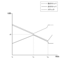
- FIG. 10 is a diagram showing an example of a graph showing changes in haptic vectors over time
- FIG. 4 is an explanatory diagram for explaining an example of a command value including amplitude information
- FIG. 9 is an explanatory diagram for explaining another example of command values including amplitude information
- FIG. 9 is an explanatory diagram for explaining another example of command values including amplitude information
- FIG. 4 is an explanatory diagram for explaining an example of operation processing of a control device according to the present disclosure
- FIG. 10 is an explanatory diagram for explaining an example of stick operation restrictions
- FIG. 10 is an explanatory diagram for explaining another example of stick motion limitation
- FIG. 10 is a diagram showing an example of a graph showing changes in haptic vectors over time
- FIG. 4
- FIG. 3 is an abstract diagram that abstracts a configuration related to haptic presentation of the operation device according to the present disclosure
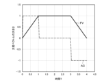
- 4 is a graph showing changes in position of each component in haptic presentation of the operation device according to the present disclosure
- FIG. 11 is an abstract diagram of a configuration related to haptic presentation of an operation device having a stopper composed of two parts
- FIG. 11 is an abstract diagram of a configuration related to haptic presentation of an operation device having a stopper composed of two parts
- FIG. 11 is an abstract diagram of a configuration related to haptic presentation of an operation device having a stopper composed of two parts
- FIG. 11 is an abstract diagram of a configuration related to haptic presentation of an operation device having a stopper composed of two parts
- FIG. 11 is an abstract diagram of a configuration related to haptic presentation of an operation device having a stopper composed of two parts
- FIG. 11 is an abstract diagram of a configuration related to haptic presentation of an operation device having a stopper composed of two parts
- FIG. 11 is
- FIG. 10 is a graph showing changes in position of each component in force presentation of an operation device having a stopper composed of two parts;
- FIG. 4 is a graph showing position changes of each configuration in force presentation of an operation device having a positive actuator that drives a positive stopper and a negative actuator that drives a negative stopper.
- FIG. 11 is an abstract diagram for explaining a modification of the shape of each configuration related to haptic presentation;
- FIG. 11 is an abstract diagram for explaining a modification of the shape of each configuration related to haptic presentation;
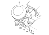
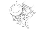
- Operation device overview An embodiment of the present disclosure relates to an operation device capable of further improving a user's operational feeling. First, with reference to FIG. 1, an outline of an operation device according to the present disclosure will be described.
- FIG. 1 is an explanatory diagram for explaining an overall overview of an operation device 1 according to the present disclosure. Recently, there is a need to provide a user with a comfortable operational feeling while presenting a haptic sensation to an operation device such as an analog stick.
- a controller used in a game can provide the user with a sense of realism and immersion by presenting haptic sensations corresponding to the character's state and actions when operating the character.
- an operation device that can be set without a haptic presentation request, such as when you want to concentrate on the action instead of always presenting the haptic.
- the operation device it may be desirable for the operation device to be capable of switching between a state in which the force sense is presented and a state in which the force sense is not presented (that is, it is possible to set whether to request the presentation of the force sense).
- the operation device 1 can be set with or without a force sense presentation request, and can improve the user's operational feeling regardless of whether the force sense is presented or not. is.
- the operation device 1 according to the present disclosure may be the entire housing (for example, a controller, etc.) including the analog stick as shown in FIG. 1, or the analog stick portion as shown in FIG. good.
- the analog stick portion as shown in FIG. 1 will be explained as the operation device 1 .
- a functional configuration example of the operation device 1 according to the present disclosure will be described below with reference to FIG. 2 .
- FIG. 2 is an explanatory diagram for explaining a functional configuration example of the operation device 1 according to the present disclosure.
- the operation device 1 is applied to stick operations in two-dimensional directions will be mainly described, but the operation device 1 according to the present disclosure can be applied to stick operations in one-dimensional directions or three-dimensional directions. is also applicable.
- the operation device 1 includes a stick 10, a limit ring 15, a stick cap 20, a rotator 30, a stopper 40, an actuator 50, an angle sensor 55, an angle sensor 60 and an origin return unit 70 .
- a stick 10 according to the present disclosure is an example of an operation unit that is tilted by a user's operation.
- the stick 10 can be tilted by the rotator 30 .
- the stick 10 can be tilted by the rotator 30 within a predetermined rotation range limited by the limit ring 15 .
- the stick 10 can be tilted by the user with the central axis of the rotating body 30A as the rotation axis. Also, the stick 10 can be tilted by the user with the central axis of the rotating body 30B as the rotation axis.
- the limiting ring 15 is a ring for rotating the rotating body 30 only within a predetermined range. For example, limit ring 15 is contacted when stick 10 is tilted a certain amount. As a result, the rotatable range of the rotating body 30 is also restricted.
- a stick cap 20 is a cap that covers the stick 10 .
- the user can tilt the stick 10 via the stick cap 20 by, for example, finger manipulation.
- the rotating body 30 rotates on the rotation axis of the rotating body 30, thereby enabling the stick 10 to be tilted within a predetermined rotation range.
- the rotating body 30A which is an example of the first movable part, allows the stick 10 to move within a predetermined range. More specifically, by rotating the central axis of the rotating body 30A as the first axis, the stick 10 can be tilted in both positive and negative directions in the rotational direction of the rotating body 30A.
- the rotating body 30B which is an example of the second movable part, rotates about the central axis of the rotating body 30B as a second axis, thereby tilting the stick 10 in both positive and negative directions in the rotation direction of the rotating body 30B.
- the central axis of the rotating body 30A and the central axis of the rotating body 30B may be orthogonal as shown in FIG.
- the rotating body 30A may have an elongated hole that does not interfere with the stick 10 when the stick 10 is tilted by the central axis of the rotating body 30B.
- the rotating body 30 has a contact portion that comes into contact with the movement of the stopper 40, which will be described later.
- the contact portion may have a convex structure as shown in FIG. 2, which will be described later in detail.
- the number of rotating bodies 30 is one, the number of stoppers 40, actuators 50, and angle sensors 55 and 60, which will be described later, may also be one.
- the stopper 40 is an example of a driven portion.
- the stopper 40 can move the contact portion of the rotating body 30 according to the driving force of the actuator 50 . Further, the stopper 40 contacts the contact portion of the rotating body 30 and can apply a load in the rotating direction of the rotating body 30 . As a result, the stick 10 is moved, and a force sensation is presented to the user via the stick 10 .
- the stopper 40 includes at least one or more parts.
- the stopper 40 shown in FIG. 2 is composed of one component. A specific example of the stopper 40 composed of two parts will be described later.
- the stopper 40A is an example of a first driven portion, and can move the contact portion in the rotation direction of the rotating body 30A. Due to the movement of the contact portion, a load is applied in the rotational direction of the rotating body 30A, and the operation device 1 can present the user with a force corresponding to the rotating direction of the rotating body 30A.
- the stopper 40B is an example of a second driven portion, and the contact portion can be moved in the rotation direction of the rotating body 30B. Due to the movement of the contact portion, a load is applied in the rotating direction of the rotating body 30B, and the operation device 1 can present the user with a force corresponding to the rotating direction of the rotating body 30B.
- Actuator 50 is an example of a driving unit driven under control of control device 100, which will be described later.
- the actuator 50A is an example of a first driving section, and can rotate the stopper 40A according to the driving force based on the command value acquired from the control device 100.
- the actuator 50B is an example of a second driving section, and can rotate the stopper 40B according to the driving force based on the command value acquired from the control device 100.
- the actuator 50 may be, for example, a DC rotary motor, but is not limited to such an example.
- the actuator 50 may be a brushless motor, a direct-acting motor, a solenoid, or any actuator that can be restricted from the left and right with a stopper structure.
- the angle sensors 55 and 60 are sensors capable of detecting angle information.
- the angle sensor 55 detects angle information of the stopper 40 .
- the angle sensor 60 detects angle information of the stick 10 .
- the origin return unit 70 has a structure that returns the stick 10 to the origin.
- the return-to-origin unit 70 is composed of a return-to-origin spring, an insert, and a slider.
- FIG. 3 is an explanatory diagram for explaining a functional configuration example of the control device 100 according to the present disclosure.
- the control device 100 according to the present disclosure includes a storage section 110, a power supply section 120, and a control section .
- control device 100 is provided by a housing (for example, a controller) that includes the operation device 1, but the control device 100 is arranged as a server at any place.
- the storage unit 110 holds software and various data.
- the storage unit 110 holds the relationship between the command value generated by the command value generation unit 135 and the voltage applied to the actuator 50 .
- the storage unit 110 may hold the relationship between the applied voltage and the torque generated by the applied voltage.
- torque is an example of driving force.
- the operation device 1 may be equipped with a sensor that detects the torque generated by the contact between the rotating body 30 and the stopper 40 .
- the sensor may then detect the torque generated by the applied voltage.
- the storage unit 110 may hold the relationship between the applied voltage and the torque detected by the sensor.
- the interface unit 131 can control the torque in a feedback manner based on the relationship held by the storage unit 110. For example, it is possible to perform control according to various conditions such as the age and sex of the user. .
- the power supply unit 120 supplies power to each component within the control device 100 .
- FIG. 3 shows an example in which the power supply unit 120 is mounted inside the control device 100 , the power supply unit 120 may be located outside the control device 100 .
- control unit 130 controls overall operations of the control device 100 .
- the control unit 130 according to the present disclosure includes, for example, an interface unit 131, an angle information reception unit 132, a communication unit 133, a setting reception unit 134, and a command value generation unit 135, as shown in FIG. .
- the interface unit 131 is a communication interface that transmits/receives signals including various information to/from the operation device 1 .
- the interface unit 131 receives angle information from the angle sensors 55 and 60 .
- the interface unit 131 also supplies the actuator 50 with a current corresponding to the command value generated by the command value generation unit 135 .
- the angle information acceptance unit 132 accepts angle information received by the interface unit 131.
- the angle information receiving section 132 receives the angle information of the stick 10 and the angle information of the stopper 40 received by the interface section 131 .
- the communication unit 133 performs various communications with other devices. For example, the communication unit 133 receives various signals from a server or a mobile terminal used by a user.
- the communication unit 133 receives information about whether or not there is a haptic presentation request set by the user on the application from the server or the mobile terminal.
- the communication unit 133 receives information about various objects on the application from the server or the mobile terminal. A specific example of information about various objects will be described later.
- the setting acceptance unit 134 accepts setting information received by the communication unit 133 .
- the setting accepting unit 134 accepts information regarding whether or not there is a haptic presentation request set by the user.
- the command value generator 135 generates a command value for driving the actuator 50 based on the angle information received by the angle information receiver 132 and the setting information received by the setting receiver 134 .
- the command value generation unit 135 calculates a force vector, which is an example of a force sense value, when a force sense presentation request is set. Also, the command value generator 135 may generate a command value based on the calculated force vector. Details regarding the calculation of the force vector and the generation of the command value will be described later.
- FIG. 4 is an explanatory diagram for explaining an overview related to haptic presentation according to the present disclosure.
- the rotor 30 has a convex structure 31 as a contact portion as shown in FIG.
- the convex structure 31 may be made of any material, but by using a material that can absorb impact, such as a cushioning material, it is possible to reduce an unintended sense of collision when presenting a force sensation to the user. .
- the user sets, for example, on the application whether or not to request the presentation of the force sensation. Then, the actuator 50B rotates the stopper 40B based on the force sense presentation request.
- FIG. 5A an example of driving the actuator 50 when the force sense presentation request is set to be present will be described.
- FIG. 5A is an explanatory diagram for explaining an example of driving the actuator 50B when the force sense presentation request is set.
- the actuator 50 rotates the stopper 40B under the control of the control device 100 .
- the actuator 50B rotates the stopper 40B according to the driving force based on the command value generated by the control device 100.
- the actuator 50B can apply a load to the rotating body 30B by contact between the end surface of the notch of the stopper 40B and the convex structure 31B of the rotating body 30B. This allows the actuator 50B to move the rotating body 30B.
- the stick 10 is also tilted with respect to the direction in which the rotating body 30B is moved.
- the operation device 1 according to the present disclosure can present the user with a force sensation according to the driving force of the actuator 50B in the direction in which the stick 10 is tilted.
- FIG. 6B an example relating to the driving of the actuator 50B when the haptic presentation request is set to be absent will be described.
- FIG. 5B is an explanatory diagram for explaining an example related to the driving of the actuator 50B when the haptic presentation request is not set.
- the actuator 50 rotates the stopper 40B under the control of the control device 100 .
- the actuator 50B moves the stopper 40B to a position where the protruded structure 31B of the rotating body 30B and the end surface of the notch of the stopper 40 do not come into contact when the stick 10 is tilted, as shown in FIG. may
- a position where the convex structure 31B of the rotating body 30B and the end surface of the notch of the stopper 40 do not contact may be expressed as a non-interfering position.
- the convex structure 31B of the rotating body 30B does not come into contact with the stopper 40B. That is, since the user is not provided with a sense of resistance corresponding to the contact, the user's operability can be further improved even when the haptic presentation request is set to be absent.
- the actuator 50 can provide the user with a haptic sensation by driving force based on the command value generated by the control device 100 .
- the process of generating command values by the control device 100 will be sequentially described.
- FIG. 6 is an explanatory diagram for explaining an example related to calculation of a force vector.
- a character C and a ball B exist in a virtual space S such as a game. Then, the user can operate the character C using the operation device 1 .
- a ball B is flying toward a character C that is at rest.
- Character C is an example of an operation object operated by a user
- ball B is an example of an interfering object that interferes with the operation object (that is, character C).
- the command value generation unit 135 calculates a haptic vector based on the information about various objects on the application received by the communication unit 133 .
- information about various objects on the application may include the characteristics of character C or the characteristics of ball B.
- the characteristics here include, for example, properties such as speed, size, elasticity, friction, electricity and surface roughness, or pre-designed scalar fields and vector fields.
- the properties of ball B may include various properties of ball B, such as flight speed, elasticity, or weight.
- the command value generator 135 calculates the force vector in the right direction. Further, the command value generator 135 calculates the magnitude of the force vector based on various information such as the speed of the ball B and the hardness (ie, elastic modulus) of the ball B.
- FIG. 6 the command value generator 135 calculates the force vector in the right direction. Further, the command value generator 135 calculates the magnitude of the force vector based on various information such as the speed of the ball B and the hardness (ie, elastic modulus) of the ball B.
- the command value generation unit 135 may calculate the magnitude of the haptic vector to be larger when the velocity of the ball B is higher than when the velocity of the ball B is low. As a result, it may be possible to more accurately present the speed and hardness of the ball to the user as a force sensation.
- the information about the target on the application may include the relative positional relationship between the operation object and the interfering object.
- information related to various positional relationships such as the position of the ball B with respect to the position of the character C may be included.
- the command value generation unit 135 may calculate a force vector based on information related to the state change of the operation device 1 .
- the information regarding the state change of the operation device 1 may include information regarding the angle at which the stick 10 is tilted.
- the character C is stopped, but it is possible for the character C to move by tilting the stick 10 by the user.
- the command value generator 135 may calculate the force vector with the angle at which the stick 10 is tilted as a starting point. This allows the command value generator 135 to calculate the force vector even when the ball B collides with the moving character C.
- command value generation unit 135 may calculate the force vector based on the elapsed time from the time when the operation device 1 started presenting the force.
- the command value generator 135 may calculate a force vector corresponding to the collision timing (for example, 0.1 seconds).
- the interfering object may be a field in which character C moves.
- the command value generator 135 may calculate a haptic vector based on a scalar field designed in advance for the field "swamp".
- the command value generation unit 135 may continuously calculate the pre-designed places where the resistance is strong and where the resistance is weak as the magnitude of the haptic vector. good. Thereby, the operation device 1 can present to the user the difficulty of moving peculiar to swamps as a force sensation.
- the command value generator 135 may calculate a force vector directed toward the origin from the angle at which the stick 10 is tilted. This may allow the user to more accurately feel the difficulty and resistance of the swamp.
- the command value generation unit 135 may, for example, select a slope, stairs, a state in which the character C has luggage, a swimming action, or a state in which the character Various states such as C's stamina may be reflected in the haptic vector.
- the command value generating unit 135 may calculate the sense of resistance when manipulating a tool used by character C as a force vector. More specifically, the command value generation unit 135 can thereby provide the user with a sense of resistance when the character C performs an action using a tool (for example, an action of drawing a bow, etc.).
- the command value generator 135 may calculate a force vector in the normal direction of the wall when the character C collides with the wall. Also, the command value generator 135 may calculate the magnitude of the haptic vector from the traveling direction of the character C or the normal line of the wall. In addition, the command value generating unit 135, for example, immediately after the character C collides with the wall (for example, about 0.5 seconds after the collision timing) calculates a large force vector, and then calculates a small force vector. good too.
- the interfering object may be an object related to character C's operation.
- object related to the operation of the character C an example of a ring-shaped command object will be described.
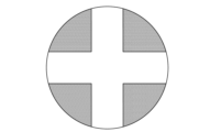
- FIG. 7 is an explanatory diagram for explaining an overview of command objects.
- a command object according to the present disclosure may be, for example, an object having ring-shaped options as shown in FIG.
- the command object consists of, for example, a reference circle (the circle containing "0" shown in FIG. 7) as the center, and a ring-shaped area (see FIG. It may also be an object having a feature surrounded by a region containing "1" to "8").
- the user may be able to display the command object on the application by, for example, performing a predetermined operation on the operation device 1, or display the command object in response to an action such as a voice uttered by the user. It may be possible to display it on the application.
- options are included in each area containing "1" to “8".
- the user can select an option in the tilted direction by tilting the stick 10 from the origin position in a certain direction of an area containing options "1" to "8".
- FIG. 8 is an explanatory diagram for explaining an example of a force vector when the stick 10 is tilted from "0" toward an area with other numbers. For example, when the user wants to select an option in a number area, the user tilts the stick 10 from the origin position toward the number area.
- the command value generation unit 135 may, for example, calculate a force vector in a direction that inhibits movement from "0" in the hatched area VH1 shown in FIG.
- the hatched area VH1 may be an area including a prescribed range from the boundary where "0" transitions to another number.
- the command value generator 135 may calculate the force vector in the direction of the arrow in the hatched area VH1 shown in FIG. . At this time, the command value generator 135 may calculate the magnitude of the force vector to increase as the stick 10 is tilted from "0" to "2" in the hatched area VH1.
- the option in the "2" area may be selected.
- the option in the area "2" may be selected when an operation related to confirmation of the option is performed. .
- FIG. 9 is an explanatory diagram for explaining an example of a force vector when the stick 10 is tilted from “1" to "2" or "8". For example, after tilting the stick 10 to select an option in the "1" area, the user may further select an option adjacent to the "1" area.
- the command value generation unit 135 may, for example, calculate a force vector in a direction that inhibits movement from "1" in the hatched area VH2 shown in FIG.
- the command value generator 135 when the user tilts the stick 10 from the area “1" toward the area "2", the command value generator 135 generates force in the direction of the arrow in the hatched area VH2 shown in FIG. You may calculate a wake vector.
- the command value generator 135 calculates the force vector in the direction of the arrow in the hatched area VH3 shown in FIG. good too.
- the command value generation unit 135 may calculate a haptic vector corresponding to the area containing the option each time the area is moved. As a result, the command value generation unit 135 can provide the user with a feeling of having crossed over the area when moving to another option area, and a feeling of being within the area after crossing over.
- the number of rings surrounding the command object may be double or more.
- the command value generator 135 may calculate a command value for controlling the actuator 50 based on the calculated force vector.
- FIGS. 10 to 16B specific examples of calculation of command values according to the present disclosure will be sequentially described.
- command value> There are, for example, two methods of presenting the haptic sensation to the user: a momentary presentation method and a continuous presentation method.
- the command values for the instantaneous presentation method and the command values for the continuous presentation method will be described below.
- the drive force of the actuator 50 causes the stopper 40 to collide with the convex structure 31.
- FIG. 10 an example of a method of presenting an instantaneous force sense will be described.
- FIG. 10 is an explanatory diagram for explaining an example of a method of presenting an instantaneous force sensation.
- the position of the stopper 40 is indicated by a solid line
- the position of the stick 10 is indicated by a broken line.
- the position of the stick 10 here indicates, more specifically, the position of the convex structure 31 of the rotating body 30 . Since the stick 10 moves in conjunction with the convex structure 31 , for convenience of explanation, the position of the convex structure 31 is assumed to be the position of the stick 10 . Also, the position of the stick 10 and the position of the stopper 40 indicate the positions of the rotor 30 around the axis.
- the violent force generated when the stopper 40 collides with the convex structure 31 increases.
- the position of the stopper 40 and the position of the stick 10 are close to each other (that is, when they are not apart from each other by a certain distance)
- the violent force generated by the collision of the stopper 40 with the convex structure 31 can be reduced.
- the actuator 50 according to the present disclosure may present an instantaneous sense of force using the relationship between the distance between the stopper 40 and the stick 10 and the violent force generated by the collision.
- the actuator 50 shifts the position of the end face of the notch of the stopper 40 to a predetermined offset from the convex structure 31 of the rotating body 30. They may be separated by a distance dx. However, when the end surface of the notch of the stopper 40 and the convex structure 31 are separated by a predetermined offset distance dx or more, the actuator 50 performs control to separate the position of the end surface of the notch of the stopper 40 from the convex structure 31. It doesn't have to be.
- the impact mode is an example of an instantaneous haptic presentation mode.
- the actuator 50 After the end surface of the notch of the stopper 40 collides with the convex structure 31 of the rotating body 30, the actuator 50 returns the position of the stopper 40 to the position before the collision (for example, the original position of the stopper 40). may Thereby, a force sensation with a greater impact can be presented to the user.
- the command value includes the amount of change in the position of the stopper 40 with respect to the time from time t3 when the position of the stopper 40 is separated by the offset distance dx to time t4 when the force is applied to the stick 10 (that is, 10 ) may be included .
- the actuator 50 Under the control of the control device 100 , moves the end face of the notch of the stopper 40 into the convex shape of the rotating body 30 with a force corresponding to the command value. It may also collide with structure 31 .
- the force generated by the collision of the convex structure 31 of the rotating body 30 with the stopper 40 momentarily presents a haptic sensation.
- the stopper 40 may be moved to a position where it does not come into contact with the convex structure 31, thereby instantaneously providing the user with a force sensation. .
- the user can be presented with a more vivid sensation of a collision with an interfering object.
- the direction of the force vector is not only the vertical direction corresponding to either one of the rotating bodies 30A or 30B, or the horizontal direction corresponding to the other, but also oblique directions including both vertical and horizontal components.
- oblique direction is expressed as one collision, it is necessary for the stopper 40A to collide with the rotating body 30A and the stopper 40B to collide with the rotating body 30B at the same timing.
- the command value generation unit 135 generates a command value such that the stoppers 40A and 40B collide with the rotating bodies 30A and 30B within an error range that does not allow the user to perceive the difference in collision timing. may be generated.
- the command value generation unit 135 may control the timing at which the interface unit 131 transmits command values to each of the actuators 50A and 50B.
- the command value generation unit 135 determines the actuator 50A corresponding to the component with the large ratio. Alternatively, a command value for driving only one of the actuators 50B may be generated.
- the command value generation unit 135 may generate a command value that instantaneously presents the user with a sense of force as notification means for notifying that the UI cursor has moved by one square or has moved to the end.
- the command value generator 135 may change the magnitude of the force sense to be presented to the user according to the number of times the force sense due to collision is presented.
- FIGS. 11A and 11B are explanatory diagrams for explaining specific examples of command values generated when the ball B collides with the character C multiple times.
- the user may have a better sense of direction when multiple collisions occur than when the user collides once.
- the command value generator 135 may generate a command value such that the feedback is the strongest for the first collision, and the strength of the feedback is gradually reduced for the second and subsequent collisions.
- the command value generator 135 may generate a command value such that the feedback is the strongest for the first collision, and the strength of the feedback is uniformly reduced for the second and subsequent collisions.
- command value generator 135 may generate a command value in which the strength of feedback from the second time onward is changed as described above, according to the number of balls B that collide with each other per unit time.
- a specific example of an instantaneous presentation method has been described above as a method of presenting a haptic sensation to the user. Vibration can be presented by repeating the momentary presentation of the sense of force due to the collision of the stopper 40 and the rotating body 30 . A specific example of vibration presentation will be described later. Next, a specific example of a continuous presentation method will be described as a method of presenting the haptic sensation to the user.
- continuous presentation method For example, as a continuous presentation method, it is assumed that the above-described character moves through a swamp, or the character draws a bow, or performs an operation using a command object.
- the command value generator 135 may first drive the actuator 50 to a position where the convex structure 31 of the rotating body 30 and the stopper 40 come into contact.
- the command value generator 135 may change the driving force of the actuator 50 according to the tilt of the operation object and the tilt of the stick 10 .
- command value generation unit 135 may switch to continuous presentation after presenting the above-described momentary haptic.
- continuous haptic presentation method an example of a continuous haptic presentation method will be described with reference to FIG. 12 .
- FIG. 12 is an explanatory diagram for explaining an example of a continuous haptic presentation method.
- the actuator 50 may perform control according to the distance between the stopper 40 and the stick 10 .
- the soft collision mode is an example of a continuous haptic presentation mode.
- the actuator 50 when the actuator 50 is set to the soft collision mode, if the distance between the end surface of the notch of the stopper 40 and the convex structure 31 of the rotating body 30 is greater than or equal to the first distance, the actuator 50 moves at the first speed.
- the rotating body 30 may be rotated.
- the first distance is, for example, the distance between the stopper 40 (more specifically, the end face of the notch of the stopper 40) and the stick 10 (more specifically, the rotating body 30) at time t1 shown in FIG. is the distance between the convex structure 31) of
- the first speed is the speed of the stopper 40 during the time t 0 to t 1 shown in FIG. good.
- the stopper 40 and stick 10 may keep a constant distance and not collide. Therefore, when the distance between the end surface of the notch of the stopper 40 and the convex structure 31 of the rotating body 30 is less than the first distance, the actuator 50 rotates at a second speed different from the above-described first speed. Body 30 may be rotated.
- the second speed is the speed of the stopper 40 during the time t 1 to t 2 shown in FIG. 12, and may be a constant speed controlled to such an extent that the collision of the stopper 40 is not perceived by the user.
- the first speed and the second speed are not limited to the examples described above.
- the first speed and the second speed may be constant speeds or speeds defined by a function such as an exponential function.
- a larger voltage is applied to the actuator 50 as the distance increases.
- a constant voltage is applied to the actuator 50 when the distance between the end surface of the notch of the stopper 40 and the convex structure 31 of the rotating body 30 reaches the first distance. Furthermore, after the end face of the notch of the stopper 40 collides with the convex structure 31 of the rotating body 30, the actuator 50 is applied with a large voltage again so that the user is presented with a continuous force sensation.
- the stopper 40 rotates quickly when it is away from the stick 10, and rotates slowly as it approaches the stick 10. It can hit the stick 10 with imperceptibly weak force.
- the command value from the application provides the user with a continuous force sensation.
- a force-related command value may be continuously sent from the application.
- the actuator 50 brings the stopper 40 closer to the stick 10 again in the above-described procedure to cause it to collide with the stick 10, thereby presenting a continuous sense of force to the user.
- actuator 50A and the actuator 50B different control standards may be used for the actuator 50A and the actuator 50B.
- actuator 50A uses the above-described first distance, first speed, and second speed as a reference for control
- actuator 50B uses a second distance and a third speed different from those of actuator 50A.
- Velocity, a fourth velocity may be used as a control criterion.
- the same control reference may be used for the actuator 50A and the actuator 50B.
- the first and second distances, the first and third velocities, and the second and fourth velocities may each indicate the same value.
- the command value generation unit 135 may generate a command value related to the motion restriction of the stick 10 when the motion restriction of the stick 10 is requested.
- FIG. 13A is an explanatory diagram for explaining an example of motion restrictions of the stick 10.
- FIG. FIG. 13A is a circle showing the movable range of the stick 10, and the command value generating section 135 may set motion limits in the hatched area, for example.
- the command value generator 135 may generate a command value that hinders the tilting action. In this case, when the user tries to incline the stick 10 to the hatched area, the user feels as if he or she is being pushed back toward the non-hatched area.
- FIG. 13B is an explanatory diagram for explaining another example of the motion limitation of the stick 10.
- the command value generation unit 135 sets the rotation range of the stick 10 as the non-hatched area of the cross key, as shown in FIG. 13B. You can limit the range. Due to the motion limitation described above, the command value generation unit 135 can provide the user with assistance related to the motion of the stick 10 .
- the command value generation unit 135 may present the user with a force sensation due to vibration.
- the command value generator 135 may generate a command value by converting the force vector into vibration, sound, or the like.
- FIG. 14 is a diagram showing an example of a graph showing changes over time in haptic vectors.
- the magnitude of the force vector shown in FIG. 14 may be, for example, the square root of the sum of the squares of the magnitude of the force vector in the vertical direction and the magnitude in the horizontal direction.
- the command value generator 135 may generate a command value including an amplitude corresponding to the calculated force vector.
- the amplitude may be expressed as an envelope.
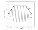
- FIG. 15 is an explanatory diagram for explaining an example of command values including amplitude information.
- the command value generator 135 calculates an envelope based on the force vector FV. Then, the command value generator 135 may generate the sinusoidal vibration VS1 based on the calculated envelope as the command value.
- FIGS. 16A and 16B are explanatory diagrams for explaining other examples of command values including amplitude information.
- the command value generator 135 may generate a command value including amplitude information corresponding to the change amount of the force vector.
- the command value generator 135 calculates the change amount AC of the force vector FV with respect to time.
- the command value generator 135 calculates an envelope based on the calculated amount of change AC. Then, the command value generator 135 may generate the sinusoidal vibration VS2 based on the calculated envelope as the command value.
- the command value generation unit 135 can notify the user of a change in the object operated by the user, for example, when the character C shown in FIG. 6 enters or exits the swamp. can be
- the command value generation unit 135 calculates the envelope based on the force vector
- the command value generation unit 135 may calculate the envelope and the frequency based on the force vector. This increases the degree of freedom related to vibration presentation, and the command value generation unit 135 can present various vibrations to the user according to the situation of the character C and the environment.
- the operation device 1 may further include a vibration motor as an example of a vibration presenting unit.
- the operation device 1 may further include a speaker for outputting a command value obtained by converting a haptic vector into sound.
- vibration may be generated by repeated collisions of a combination of at least one of the stopper 40A and the rotating body 30A and the stopper 40B and the rotating body 30B.
- the stopper 40 is an example of a vibration presenting section.
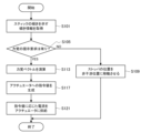
- FIG. 17 is an explanatory diagram for explaining an example of operation processing of the control device 100 according to the present disclosure.
- the communication unit 133 acquires tilt information indicating the tilt of the stick 10 (S101).
- control unit 130 determines whether or not the user has set a haptic presentation request (S105). If no presentation request is set (S105/No), the process proceeds to S109, and if presentation request is set (S105/Yes), the process proceeds to S113.
- the interface unit 131 moves the position of the stopper 40 to a non-interfering position with the stick (S109), and the control device 100 ends the process.
- the command value generation unit 135 calculates a haptic vector based on the information about the target on the application (S113).
- the command value generator 135 calculates a command value for the actuator 50 based on the calculated force vector (S117).
- the interface unit 131 supplies a current corresponding to the calculated command value to the actuator 50 to drive the actuator 50 (S121), and the control device 100 ends the processing.
- the haptic presentation method of the operation device 1 according to the present disclosure is not limited to the examples described above.
- a specific example of the haptic presentation method of the operation device 1 will be described.
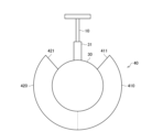
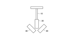
- FIG. 18 is an abstract diagram that abstracts the configuration related to haptic presentation of the operation device 1 according to the present disclosure.
- the stopper 40 can present positive and negative force sensations to the user by the collision of the rotating body 30 against the convex structure 31 .
- the stopper 40 that generates force in the positive direction is referred to as the positive stopper 410
- the stopper 40 that generates force in the negative direction is referred to as the negative stopper 420.
- the stopper 40 configured by one part the right side of the broken line shown in FIG.
- the end surface 411 of the positive stopper 410 contacts (collides with) the convex structure 31 of the rotating body 30
- the user is presented with a force in the positive direction.
- the end surface 421 of the negative stopper 420 contacts (collides with) the convex structure 31 of the rotating body 30, the force in the negative direction is presented to the user.
- FIG. 19 is a graph showing changes in the position of each configuration in haptic presentation of the operation device 1 according to the present disclosure.
- the position of the stick 10 is indicated by a dashed line
- the position of the positive stopper 410 is indicated by a solid line
- the position of the negative stopper 420 is indicated by a dashed line.
- FIG. 19 illustrates an example in which the actuator 50 controls the stopper 40 so as to present a force sensation toward the origin position x0 of the stick 10.
- FIG. 19 illustrates an example in which the actuator 50 controls the stopper 40 so as to present a force sensation toward the origin position x0 of the stick 10.
- the actuator 50 brings the negative stopper 420 into contact with the stick 10 tilted in the positive direction, thereby presenting a force sensation in the negative direction. Then, at time t11 , after the stick 10 reaches the origin position x0, when the stick 10 is further tilted in the negative direction, the actuator 50 controls the positive stopper 410 to contact the stick 10. , presents a force sensation in the positive direction. Then, when a command value for ending the force sense presentation is obtained (time t 13 shown in FIG. 19), the actuator 50 moves the stopper 40 to a position where it does not come into contact with the stick 10 .
- the stopper 40 when the stopper 40 is composed of a single component, the positive stopper 410 and the negative stopper 420 move in conjunction with each other.
- a blank time t 11 to t 12 of haptic presentation may occur according to the width. Occurrence of the blank times t 11 to t 12 may cause an event in which the desired haptic sensation is not presented to the user.
- the stopper 40 may be composed of two separate parts, a positive stopper 410 and a negative stopper 420 .
- the actuator 50 may rotate the positive stopper 410 and the negative stopper 420 in line-symmetrical rotational directions by converting the rotation of the actuator 50 using a gear.
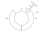
- 20A to 20D are abstract diagrams that abstract the configuration related to the haptic presentation of the operation device 1 having the stopper 40 composed of two parts.
- the positive stopper 410 and the negative stopper 420 have a pinching structure by converting the driving force of the actuator 50 with a gear.
- the pinching configuration of the positive and negative stoppers 410, 420 allows the stoppers 40 to have notches that dynamically open and close, as shown in FIGS. 20A-20D.
- FIG. 21 is a graph showing changes in position of each component in presenting the force sensation of the operation device 1 having the stopper 40 composed of two parts.
- the graph shown in FIG. 21 is a graph showing the position of each configuration (stick 10, positive stopper 410 and negative stopper 420) shown in FIG.
- each component of the operation device 1 shown in FIGS. 20A and 20B is indicated by each line (solid line, dashed line, dashed line) at times t 0 to t 21 shown in FIG. 21, and FIGS. 21 are indicated by lines (solid line, dashed line, dashed-dotted line) at times t 21 to t 22 shown in FIG.
- the positive stopper 410 and the negative stopper 420 that constitute the stopper 40 rotate so as to sandwich the convex structure 31 according to the driving force of the actuator 50 .
- the negative stopper 420 rotates according to the driving force of the actuator 50 so as to push back the position of the convex structure 31 at time t0 to the origin position x0.
- the positive stopper 410 is interlocked with the rotation of the negative stopper 420 and rotates in the direction opposite to the direction of rotation of the negative stopper 420 (that is, in the rotational direction of line symmetry).
- the width of the notch of the stopper 40 is dynamically narrowed, and the blank time of force sense presentation (time t 11 to t 12 shown in FIG. 19) can be reduced. .
- the positive stopper 410 and the negative stopper 420 are driven by the driving force of one actuator 50, but the operation device 1 according to the present disclosure drives the positive stopper 410.
- a positive actuator and a negative actuator driving the negative stopper 420 may each be provided.
- FIG. 22 is a graph showing changes in position of each configuration in force presentation of the operation device 1 having a positive actuator that drives the positive stopper 410 and a negative actuator that drives the negative stopper 420.
- the positive actuator and the negative actuator may be collectively expressed as a plurality of actuators 50 .
- the positive stopper 410 and the negative stopper 420 can operate independently as shown in FIG. can be switched between positive and negative without delay (that is, without blank time). Further, by operating a plurality of actuators 50, an arbitrary stick position ax can be changed as appropriate.
- the actuator 50 moves the positive stopper 410 and the negative stopper 420 to the non-interfering position of the stick 10 .
- the actuator 50 moves the positive stopper 410 and the negative stopper 420 to the non-interfering position of the stick 10 .
- the number of parts constituting the stopper 40 and the number of actuators 50 corresponding to the number of parts are not limited to one or two.
- the number of parts constituting the stopper 40 and the number of actuators 50 corresponding to the number of parts may be three or more.
- each configuration for example, the rotating body 30 and the stopper 40 related to the haptic presentation is not limited to the above examples.
- modified examples of each configuration related to haptic presentation will be described with reference to FIGS. 23A and 23B.
- Modification 23A and 23B are abstract diagrams for explaining a modification of the shape of each configuration (for example, rotating body 30 and stopper 40) related to force presentation.
- each configuration for example, rotating body 30 and stopper 40
- the stopper 40 may have a convex structure. At this time, the stopper 40 may not have a notch.
- each configuration related to the force sense presentation may be a structure capable of limiting the movable range of the stick 10.
- the shape of the stopper 40 has a notch as shown in FIG. 23B. It may be a simpler structure.
- the stopper 40 is made up of two parts, it is possible to reduce the weight of the operation device 1 by reducing the size of the two parts of the stopper 40 .
- the size relationship between the convex structure 31 of the rotating body 30 and the notch of the stopper 40 is not limited to the above example.
- the size of the convex structure 31 is not particularly limited as long as it fits in the notch of the stopper 40 .
- the operation device 1 is used for applications such as games, but the application of the operation device 1 according to the present disclosure is not limited to such examples.
- the operation device 1 according to the present disclosure may be used in applications such as remote controllers, operation of medical equipment, controllers for mobile robots and drones, and operation of electric wheelchairs.
- the stick 10 according to the present disclosure has been described as a rotating stick using the rotating body 30, but the stick 10 may be a sliding stick.
- the stick 10 according to the present disclosure has been described as a two-dimensional stick that can be tilted two-dimensionally. It may even be a three-dimensional stick that is possible. Note that when the stick 10 is two-dimensional or more, the command value generation unit 135 according to the present disclosure decomposes the haptic vector into components in each dimension and calculates the A haptic can be presented to the user.
- each component of the operation device 1 has been described with reference to FIG. 2, the arrangement of the components of the operation device 1 is not limited to this example.
- Each component such as the actuator 50 may be arranged at any position depending on the type and arrangement of gears.
- the actuator 50A rotates the stopper 40A to bring the end surface of the notch of the rotating body 30A into contact with the abutting portion of the rotating body 30A, and the actuator 50B rotates the stopper 40B, causing the stopper to rotate.
- An example of bringing the end face of the notch 40B into contact with the contact portion of the rotating body 30B has been described.
- the actuators 50A and 50B are independently controlled when the rotating bodies 30A and 30B rotate, but the structure for suppressing the tilting motion of the stick 10 is not limited to this example.
- the stopper 40A may be a mechanism that applies a brake to the rotating body 30 by friction instead of contact by the end face of the notch.
- it may be a mechanism that brakes both the rotating shaft by the rotating body 30A and the rotating shaft by the rotating body 30B at the same time.
- one actuator 50 can suppress the rotation of two axes.
- the command value generation unit 135 may perform correction related to erroneous input prevention according to such a situation. Then, the command value generation unit 135 may generate a command value corrected for preventing erroneous input.
- the command value generation unit 135 may provide several seconds of non-operable time with the stick 10 after momentarily presenting the haptic.
- the command value generation unit 135 returns the stick 10 to the vicinity of the position before the contact portion between the stopper 40 and the rotating body 30 collided. It is not necessary to accept the operation input by the stick 10 until.
- the command value generation unit 135 may perform control so that the presentation of the force sense is turned off when a predetermined angle is reached from the angle reference of the stick 10 after presenting the force sense. Specifically, the command value generation unit 135 may perform control such that, after presenting the force sense, presentation of the force sense is turned off at +5° from the origin. This can prevent the stick 10 from rebounding at an unintended angle. Note that the angle reference is not limited to the origin.
- each step in the processing of the control device 100 in this specification does not necessarily have to be processed in chronological order according to the order described as the flowchart.
- each step in the processing of the information processing system may be processed in an order different from the order described as the flowchart or in parallel.
- an operation unit that is moved by a user's operation; a first movable portion that enables the operation portion to move within a predetermined range; a first drive; a first driven part including at least one component and capable of moving a contact part of the first movable part according to the driving force of the first driving part; operating device with (2) a second movable section that allows the operation section to move along a second axis that is different from the first axis along which the operation section can be moved by the first movable section; a second drive; a second driven part that includes at least one or more components and is capable of moving a contact part of the second movable part according to the driving force of the second driving part;
- the operation device according to (1) above, further comprising: (3)
- the first movable part is a first rotating body that enables the operation unit to be tilted with respect to the first axis by the user's operation;
- the second movable part is A second rotating body that allows the operation
- a component included in the first driven portion and the second driven portion has an end surface;
- the first rotating body and the second rotating body are It is movable by contact between the end surface and the contact portion,
- the first driven portion and the second driven portion have cutouts,
- the first rotating body and the second rotating body are It is movable by contact between the end surface of the notch and the contact portion,
- the first driving section and the second driving section are Rotating the first driven part or the second driven part based on the presence or absence of a preset force sense presentation request;
- the operation device according to (4) or (5) are
- the first driving section and the second driving section are rotating the first driven part or the second driven part when the haptic presentation request is set to be present;
- the first driving section and the second driving section are When the haptic presentation request is set to ON, the rotational direction of the first rotating body is changed by the contact between the first driven portion and the contact portion of the first rotating body according to the driving force. and applying a load in the direction of rotation of the second rotating body due to contact between the second driven portion and the contact portion of the second rotating body.
- the operation device according to (7) above.
- the first driving section and the second driving section are The first driven portion and the second driven portion are positioned so as not to come into contact with each other when the operation portion is tilted within the predetermined rotation range when the force sense presentation request is set to none. move the The operation device according to (7) or (8).
- the driving forces of the first driving section and the second driving section are based on a haptic value based on the characteristics of an operation object operated by tilting the operation unit; The operation device according to any one of (3) to (9).
- the haptic value is calculated based on the characteristics of an interfering object that interferes with the operation object; The operation device according to (10) above.
- the haptic value is Calculated based on the angle at which the operation unit is tilted, The operation device according to (10) or (11).
- the haptic value is Calculated based on the elapsed time since the driving force was presented, The operation device according to any one of (10) to (12).
- the driving force is Based on a command value for driving the first driving unit or the second driving unit generated based on the force sense value, The operation device according to any one of (10) to (13).
- the command value is When presenting a momentary haptic, the strength of the feedback varies depending on the number of times the haptic is presented. The operation device according to (14) above.
- the first drive unit When the momentary force sense presentation mode is set, after the end surface of the first driven portion is separated from the contact portion of the first rotating body by a predetermined offset distance, the first driven portion is moved. colliding the end surface of the driving portion with the contact portion of the first rotating body;
- the second drive unit When the momentary force sense presentation mode is set, after the end surface of the second driven part is separated from the contact part of the second rotating body by a predetermined offset distance, the second driven part is moved. causing the end surface of the part to collide with the contact part of the second rotating body;
- the operation device according to (14) or (15).
- the command value is Generated based on the continuously calculated force sense value when continuously presenting the sense of force, The operation device according to any one of (14) to (16).
- the first drive unit When the continuous haptic presentation mode is set, if the distance between the end surface of the first driven portion and the contact portion of the first rotating body is equal to or greater than the first distance, the first and the distance between the end surface of the first driven portion and the contact portion of the first rotating body is less than the first distance, the second speed to rotate the first rotating body with The second drive unit When the continuous haptic presentation mode is set and the distance between the end surface of the second driven portion and the contact portion of the second rotating body is equal to or greater than the second distance, the third A fourth speed when the second rotating body is rotated at a speed and the distance between the end surface of the second driven portion and the contact portion of the second rotating body is less than the second distance rotating the second rotating body with The operation device according to any one of (14) to (17).
Abstract
[Problem] To further improve a user's operation sensation when operating a stick that can be moved in both positive and negative directions. [Solution] An operation device comprising: an operation part that is moved by means of operation by a user; a first movable part that makes it possible for the operation part to be moved within a prescribed range; a first driving part; and a first driven part that includes at least one component and that, in accordance with the driving force of the first driving part, can move an abutting section of the first movable part.
Description
本開示は、操作デバイスに関する。
The present disclosure relates to an operation device.
近年、ユーザの操作に応じた力覚をユーザに提示する技術が開発されている。例えば、特許文献1では、1次元方向であり、且つ、正負のいずれか一方の方向に移動させることが可能なトリガーに対して、力覚のON、OFFの切り替えが可能な操作デバイスが開示されている。
In recent years, technology has been developed that presents the user with a haptic sensation according to the user's operation. For example, Patent Literature 1 discloses an operation device capable of switching between ON and OFF of the force sense for a trigger that is one-dimensional and can be moved in either the positive or negative direction. ing.
しかし、特許文献1に記載の技術では、1次元方向のトリガー操作に対しては適用可能であるものの、例えば、力覚の提示に際して精密な制御が必要であり、また、2次元方向または3次元方向や、正負の両方向に移動させることが可能なスティック操作に対して拡張することが困難であった。
However, although the technique described in Patent Document 1 can be applied to a one-dimensional trigger operation, for example, it requires precise control when presenting a force sensation, and also requires two-dimensional or three-dimensional trigger operation. It was difficult to extend to a stick operation that can move in both positive and negative directions.
そこで、本開示では、正負の両方向に移動させることが可能なスティックの操作に際して、ユーザの操作感をより向上させることが可能な、新規かつ改良された操作デバイスを提案する。
Therefore, the present disclosure proposes a new and improved operation device that can further improve the user's operational feeling when operating a stick that can be moved in both positive and negative directions.
本開示によれば、ユーザの操作により移動される操作部と、所定の範囲内で前記操作部を移動させることを可能にする第1の可動部と、第1の駆動部と、少なくとも1以上の部品を含み、前記第1の駆動部の駆動力に応じて、前記第1の可動部の当接部を移動可能である第1の被駆動部と、を有する操作デバイスが提供される。
According to the present disclosure, an operating section that is moved by a user's operation, a first movable section that allows the operating section to move within a predetermined range, a first driving section, and at least one or more and a first driven portion capable of moving the contact portion of the first movable portion according to the driving force of the first driving portion.
以下に添付図面を参照しながら、本開示の好適な実施の形態について詳細に説明する。なお、本明細書及び図面において、実質的に同一の機能構成を有する構成要素については、同一の符号を付することにより重複説明を省略する。
Preferred embodiments of the present disclosure will be described in detail below with reference to the accompanying drawings. In the present specification and drawings, constituent elements having substantially the same functional configuration are denoted by the same reference numerals, thereby omitting redundant description.
また、以下に示す項目順序に従って当該「発明を実施するための形態」を説明する。
1.操作デバイスの概要
1.1.概要
1.2.操作デバイス1の機能構成例
1.3.制御装置100の機能構成例
2.実施例
2.1.力覚提示に係る概要
2.2.力覚ベクトルの演算
2.3.指令値の生成
3.動作処理例
4.力覚提示方法の具体例
5.補足 In addition, the "Mode for Carrying Out the Invention" will be explained according to the order of items shown below.
1. Outline of operation device 1.1. Overview 1.2. Functional Configuration Example ofOperation Device 1 1.3. Functional configuration example of control device 100 2 . Example 2.1. Overview of haptic presentation 2.2. Calculation of haptic vector 2.3. Generation of command values 3 . Example of operation processing 4. Concrete example of haptic presentation method5. supplement
1.操作デバイスの概要
1.1.概要
1.2.操作デバイス1の機能構成例
1.3.制御装置100の機能構成例
2.実施例
2.1.力覚提示に係る概要
2.2.力覚ベクトルの演算
2.3.指令値の生成
3.動作処理例
4.力覚提示方法の具体例
5.補足 In addition, the "Mode for Carrying Out the Invention" will be explained according to the order of items shown below.
1. Outline of operation device 1.1. Overview 1.2. Functional Configuration Example of
<<1.操作デバイスの概要>>
本開示の一実施形態は、ユーザの操作感をより向上させることが可能な操作デバイスに関する。まず、図1を参照し、本開示に係る操作デバイスの概要を説明する。 <<1. Operation device overview >>
An embodiment of the present disclosure relates to an operation device capable of further improving a user's operational feeling. First, with reference to FIG. 1, an outline of an operation device according to the present disclosure will be described.
<1.1.概要>
図1は、本開示に係る操作デバイス1の全体概要を説明するための説明図である。昨今、アナログスティック等の操作デバイスに力覚を提示しつつ、ユーザに快適な操作感を提供したいといったニーズがある。 <1.1. Overview>
FIG. 1 is an explanatory diagram for explaining an overall overview of anoperation device 1 according to the present disclosure. Recently, there is a need to provide a user with a comfortable operational feeling while presenting a haptic sensation to an operation device such as an analog stick.
図1は、本開示に係る操作デバイス1の全体概要を説明するための説明図である。昨今、アナログスティック等の操作デバイスに力覚を提示しつつ、ユーザに快適な操作感を提供したいといったニーズがある。 <1.1. Overview>
FIG. 1 is an explanatory diagram for explaining an overall overview of an
例えば、ゲームに用いるコントローラでは、キャラクターの操作時においてキャラクターの状態や動作に対応する力覚が提示されることで、ユーザに臨場感や没入感を提供し得る。
For example, a controller used in a game can provide the user with a sense of realism and immersion by presenting haptic sensations corresponding to the character's state and actions when operating the character.
また、テレビに用いるリモートコントローラや、ゲーム内または車内でのUI(User Interface)では、各種スイッチの押下に対応する力覚が提示されることで、ユーザビリティを向上し得る。
In addition, usability can be improved by presenting haptic sensations corresponding to the pressing of various switches on remote controllers used for televisions and in-game or in-vehicle UIs (User Interfaces).
また、常に力覚が提示されるのではなく、動作に集中したい場合等、力覚の提示要求を無しに設定が可能な操作デバイスのニーズもある。即ち、操作デバイスは、力覚が提示される状態と力覚が提示されない状態を切り替えることが可能(即ち、力覚の提示要求を有り/無しの設定が可能)なことが望ましい場合がある。
In addition, there is a need for an operation device that can be set without a haptic presentation request, such as when you want to concentrate on the action instead of always presenting the haptic. In other words, it may be desirable for the operation device to be capable of switching between a state in which the force sense is presented and a state in which the force sense is not presented (that is, it is possible to set whether to request the presentation of the force sense).
そこで、本開示に係る操作デバイス1は、力覚の提示要求を有りまたは無しに設定することが可能であり、且つ、力覚の提示有無のいずれにおいてもユーザの操作感を向上させることが可能である。
Therefore, the operation device 1 according to the present disclosure can be set with or without a force sense presentation request, and can improve the user's operational feeling regardless of whether the force sense is presented or not. is.
なお、本開示に係る操作デバイス1は、図1に示すようなアナログスティックを含む筐体全体(例えば、コントローラ等)であってもよいし、図1に示すようなアナログスティック部分であってもよい。本明細書では、説明の便宜上、図1に示すようなアナログスティック部分を操作デバイス1として説明する。以下、図2を参照し、本開示に係る操作デバイス1の機能構成例を説明する。
Note that the operation device 1 according to the present disclosure may be the entire housing (for example, a controller, etc.) including the analog stick as shown in FIG. 1, or the analog stick portion as shown in FIG. good. In this specification, for convenience of explanation, the analog stick portion as shown in FIG. 1 will be explained as the operation device 1 . A functional configuration example of the operation device 1 according to the present disclosure will be described below with reference to FIG. 2 .
<1.2.操作デバイス1の機能構成例>
図2は、本開示に係る操作デバイス1の機能構成例を説明するための説明図である。本明細書では、操作デバイス1が二次元方向のスティック操作に対して適用する場合について主に説明するが、本開示に係る操作デバイス1は、一次元方向または三次元方向のスティック操作に対しても適用可能である。 <1.2. Functional Configuration Example ofOperation Device 1>
FIG. 2 is an explanatory diagram for explaining a functional configuration example of theoperation device 1 according to the present disclosure. In this specification, a case where the operation device 1 is applied to stick operations in two-dimensional directions will be mainly described, but the operation device 1 according to the present disclosure can be applied to stick operations in one-dimensional directions or three-dimensional directions. is also applicable.
図2は、本開示に係る操作デバイス1の機能構成例を説明するための説明図である。本明細書では、操作デバイス1が二次元方向のスティック操作に対して適用する場合について主に説明するが、本開示に係る操作デバイス1は、一次元方向または三次元方向のスティック操作に対しても適用可能である。 <1.2. Functional Configuration Example of
FIG. 2 is an explanatory diagram for explaining a functional configuration example of the
図2に示すように、本開示に係る操作デバイス1は、スティック10と、制限リング15と、スティックキャップ20と、回転体30と、ストッパ40と、アクチュエータ50と、角度センサ55と、角度センサ60と、原点復帰部70と、を有する。
As shown in FIG. 2, the operation device 1 according to the present disclosure includes a stick 10, a limit ring 15, a stick cap 20, a rotator 30, a stopper 40, an actuator 50, an angle sensor 55, an angle sensor 60 and an origin return unit 70 .
(スティック10)
本開示に係るスティック10は、ユーザの操作により傾けられる操作部の一例である。例えば、スティック10は、回転体30により傾けることが可能である。より具体的には、スティック10は、回転体30により制限リング15により制限された所定の回転範囲内で傾けることが可能である。 (Stick 10)
Astick 10 according to the present disclosure is an example of an operation unit that is tilted by a user's operation. For example, the stick 10 can be tilted by the rotator 30 . More specifically, the stick 10 can be tilted by the rotator 30 within a predetermined rotation range limited by the limit ring 15 .
本開示に係るスティック10は、ユーザの操作により傾けられる操作部の一例である。例えば、スティック10は、回転体30により傾けることが可能である。より具体的には、スティック10は、回転体30により制限リング15により制限された所定の回転範囲内で傾けることが可能である。 (Stick 10)
A
例えば、スティック10は、回転体30Aの中心軸を回転軸としてユーザにより傾けられることが可能である。また、スティック10は、回転体30Bの中心軸を回転軸としてユーザに傾けられることが可能である。
For example, the stick 10 can be tilted by the user with the central axis of the rotating body 30A as the rotation axis. Also, the stick 10 can be tilted by the user with the central axis of the rotating body 30B as the rotation axis.
(制限リング15)
本開示に係る制限リング15は、回転体30を所定の範囲内でのみ回転させるためのリングである。例えば、制限リング15は、スティック10が一定値傾けられた際に接触される。この結果、回転体30の回転可能な範囲も制限される。 (Restriction ring 15)
The limitingring 15 according to the present disclosure is a ring for rotating the rotating body 30 only within a predetermined range. For example, limit ring 15 is contacted when stick 10 is tilted a certain amount. As a result, the rotatable range of the rotating body 30 is also restricted.
本開示に係る制限リング15は、回転体30を所定の範囲内でのみ回転させるためのリングである。例えば、制限リング15は、スティック10が一定値傾けられた際に接触される。この結果、回転体30の回転可能な範囲も制限される。 (Restriction ring 15)
The limiting
(スティックキャップ20)
本開示に係るスティックキャップ20は、スティック10に被せるキャップである。ユーザは、例えば手指による操作で、スティックキャップ20を介してスティック10を傾けることが可能である。 (Stick cap 20)
Astick cap 20 according to the present disclosure is a cap that covers the stick 10 . The user can tilt the stick 10 via the stick cap 20 by, for example, finger manipulation.
本開示に係るスティックキャップ20は、スティック10に被せるキャップである。ユーザは、例えば手指による操作で、スティックキャップ20を介してスティック10を傾けることが可能である。 (Stick cap 20)
A
(回転体30)
本開示に係る回転体30は、当該回転体30の回転軸で回転することにより、所定の回転範囲内でスティック10を傾けることを可能にする。 (Rotating body 30)
The rotatingbody 30 according to the present disclosure rotates on the rotation axis of the rotating body 30, thereby enabling the stick 10 to be tilted within a predetermined rotation range.
本開示に係る回転体30は、当該回転体30の回転軸で回転することにより、所定の回転範囲内でスティック10を傾けることを可能にする。 (Rotating body 30)
The rotating
例えば、第1の可動部の一例である回転体30Aは、所定の範囲内でスティック10を移動させることを可能にする。より具体的には、回転体30Aの中心軸を第1の軸として回転することにより、スティック10を回転体30Aの回転方向における正負の両方向に傾けることを可能にする。
For example, the rotating body 30A, which is an example of the first movable part, allows the stick 10 to move within a predetermined range. More specifically, by rotating the central axis of the rotating body 30A as the first axis, the stick 10 can be tilted in both positive and negative directions in the rotational direction of the rotating body 30A.
また、第2の可動部の一例である回転体30Bは、当該回転体30Bの中心軸を第2の軸として回転することにより、スティック10を回転体30Bの回転方向における正負の両方向に傾けることを可能にする。なお、例えば、回転体30Aの中心軸と、回転体30Bの中心軸は、例えば図2に示すように直交してもよい。
Further, the rotating body 30B, which is an example of the second movable part, rotates about the central axis of the rotating body 30B as a second axis, thereby tilting the stick 10 in both positive and negative directions in the rotation direction of the rotating body 30B. enable In addition, for example, the central axis of the rotating body 30A and the central axis of the rotating body 30B may be orthogonal as shown in FIG.
また、例えば、回転体30Aは、スティック10が回転体30Bの中心軸により傾けられた際にスティック10と干渉しないような長穴を有していてもよい。
Also, for example, the rotating body 30A may have an elongated hole that does not interfere with the stick 10 when the stick 10 is tilted by the central axis of the rotating body 30B.
また、本開示に係る回転体30は、後述するストッパ40の移動により接触される当接部を有する。例えば、当接部は、図2に示すような凸状の構造であってもよいが詳細は後述する。
In addition, the rotating body 30 according to the present disclosure has a contact portion that comes into contact with the movement of the stopper 40, which will be described later. For example, the contact portion may have a convex structure as shown in FIG. 2, which will be described later in detail.
なお、本明細書では、回転体30が図2に示すように回転体30Aおよび回転体30Bのように2つある例を主に説明するが、回転体30の数は1つであってもよい。
In this specification, an example in which there are two rotating bodies 30, such as rotating body 30A and rotating body 30B as shown in FIG. 2, will be mainly described. good.
また、回転体30の数が1つであった場合、後述するストッパ40、アクチュエータ50、角度センサ55、60の各々の数も1つであってもよい。
Also, if the number of rotating bodies 30 is one, the number of stoppers 40, actuators 50, and angle sensors 55 and 60, which will be described later, may also be one.
(ストッパ40)
本開示に係るストッパ40は、被駆動部の一例である。ストッパ40は、アクチュエータ50の駆動力に応じて、回転体30が有する当接部を移動可能である。また、ストッパ40は、回転体30が有する当接部を接触し、回転体30の回転方向に対して荷重を印加することが可能である。これにより、スティック10が移動されることや、スティック10を介してユーザに力覚が提示される。 (Stopper 40)
Thestopper 40 according to the present disclosure is an example of a driven portion. The stopper 40 can move the contact portion of the rotating body 30 according to the driving force of the actuator 50 . Further, the stopper 40 contacts the contact portion of the rotating body 30 and can apply a load in the rotating direction of the rotating body 30 . As a result, the stick 10 is moved, and a force sensation is presented to the user via the stick 10 .
本開示に係るストッパ40は、被駆動部の一例である。ストッパ40は、アクチュエータ50の駆動力に応じて、回転体30が有する当接部を移動可能である。また、ストッパ40は、回転体30が有する当接部を接触し、回転体30の回転方向に対して荷重を印加することが可能である。これにより、スティック10が移動されることや、スティック10を介してユーザに力覚が提示される。 (Stopper 40)
The
また、ストッパ40は、少なくとも1以上の部品を含む。図2に示すストッパ40は、1つの部品により構成される。2つの部品により構成されるストッパ40の具体例については後述する。
Also, the stopper 40 includes at least one or more parts. The stopper 40 shown in FIG. 2 is composed of one component. A specific example of the stopper 40 composed of two parts will be described later.
例えば、ストッパ40Aは、第1の被駆動部の一例であり、回転体30Aの回転方向に当接部を移動可能である。当接部の移動により、回転体30Aの回転方向に荷重が印加され、操作デバイス1は、ユーザに回転体30Aの回転方向に対応した力覚を提示することが可能になる。
For example, the stopper 40A is an example of a first driven portion, and can move the contact portion in the rotation direction of the rotating body 30A. Due to the movement of the contact portion, a load is applied in the rotational direction of the rotating body 30A, and the operation device 1 can present the user with a force corresponding to the rotating direction of the rotating body 30A.
また、ストッパ40Bは、第2の被駆動部の一例であり、回転体30Bの回転方向に当接部を移動可能である。当接部の移動により、回転体30Bの回転方向に荷重が印加され、操作デバイス1は、ユーザに回転体30Bの回転方向に対応した力覚を提示することが可能になる。
Also, the stopper 40B is an example of a second driven portion, and the contact portion can be moved in the rotation direction of the rotating body 30B. Due to the movement of the contact portion, a load is applied in the rotating direction of the rotating body 30B, and the operation device 1 can present the user with a force corresponding to the rotating direction of the rotating body 30B.
(アクチュエータ50)
本開示に係るアクチュエータ50は、後述する制御装置100の制御に従って駆動する駆動部の一例である。例えば、アクチュエータ50Aは、第1の駆動部の一例であり、制御装置100から取得された指令値に基づく駆動力に応じて、ストッパ40Aを回転させることが可能である。 (Actuator 50)
Actuator 50 according to the present disclosure is an example of a driving unit driven under control ofcontrol device 100, which will be described later. For example, the actuator 50A is an example of a first driving section, and can rotate the stopper 40A according to the driving force based on the command value acquired from the control device 100.
本開示に係るアクチュエータ50は、後述する制御装置100の制御に従って駆動する駆動部の一例である。例えば、アクチュエータ50Aは、第1の駆動部の一例であり、制御装置100から取得された指令値に基づく駆動力に応じて、ストッパ40Aを回転させることが可能である。 (Actuator 50)
Actuator 50 according to the present disclosure is an example of a driving unit driven under control of
また、アクチュエータ50Bは、第2の駆動部の一例であり、制御装置100から取得された指令値に基づく駆動力に応じて、ストッパ40Bを回転させることが可能である。
Further, the actuator 50B is an example of a second driving section, and can rotate the stopper 40B according to the driving force based on the command value acquired from the control device 100.
なお、本開示に係るアクチュエータ50は、例えば、DC回転モータであってもよいが係る例に限定されない。例えば、アクチュエータ50は、ブラシレスモータ、直動モータ、ソレノイド、またはストッパ構造で左右からの制限が可能な任意のアクチュエータであってもよい。
The actuator 50 according to the present disclosure may be, for example, a DC rotary motor, but is not limited to such an example. For example, the actuator 50 may be a brushless motor, a direct-acting motor, a solenoid, or any actuator that can be restricted from the left and right with a stopper structure.
(角度センサ55、60)
本開示に係る角度センサ55、60は、角度情報を検出可能なセンサである。例えば、角度センサ55は、ストッパ40の角度情報を検出する。また、角度センサ60は、スティック10の角度情報を検出する。 (Angle sensors 55, 60)
The angle sensors 55 and 60 according to the present disclosure are sensors capable of detecting angle information. For example, the angle sensor 55 detects angle information of thestopper 40 . Also, the angle sensor 60 detects angle information of the stick 10 .
本開示に係る角度センサ55、60は、角度情報を検出可能なセンサである。例えば、角度センサ55は、ストッパ40の角度情報を検出する。また、角度センサ60は、スティック10の角度情報を検出する。 (Angle sensors 55, 60)
The angle sensors 55 and 60 according to the present disclosure are sensors capable of detecting angle information. For example, the angle sensor 55 detects angle information of the
(原点復帰部70)
本開示に係る原点復帰部70は、スティック10を原点に復帰させる構造である。例えば、原点復帰部70は、原点復帰用のバネ、インサートおよびスライダにより構成される。 (Origin return unit 70)
Theorigin return unit 70 according to the present disclosure has a structure that returns the stick 10 to the origin. For example, the return-to-origin unit 70 is composed of a return-to-origin spring, an insert, and a slider.
本開示に係る原点復帰部70は、スティック10を原点に復帰させる構造である。例えば、原点復帰部70は、原点復帰用のバネ、インサートおよびスライダにより構成される。 (Origin return unit 70)
The
以上、本開示に係る操作デバイス1の機能構成例を説明した。続いて、図3を参照し、本開示に係る制御装置100の機能構成例を説明する。
The functional configuration example of the operation device 1 according to the present disclosure has been described above. Next, a functional configuration example of the control device 100 according to the present disclosure will be described with reference to FIG. 3 .
<1.3.制御装置100の機能構成例>
図3は、本開示に係る制御装置100の機能構成例を説明するための説明図である。図3に示すように本開示に係る制御装置100は、記憶部110と、電源部120と、制御部130と、を備える。 <1.3. Functional Configuration Example ofControl Device 100>
FIG. 3 is an explanatory diagram for explaining a functional configuration example of thecontrol device 100 according to the present disclosure. As shown in FIG. 3 , the control device 100 according to the present disclosure includes a storage section 110, a power supply section 120, and a control section .
図3は、本開示に係る制御装置100の機能構成例を説明するための説明図である。図3に示すように本開示に係る制御装置100は、記憶部110と、電源部120と、制御部130と、を備える。 <1.3. Functional Configuration Example of
FIG. 3 is an explanatory diagram for explaining a functional configuration example of the
本明細書では、本開示に係る制御装置100が操作デバイス1を含む筐体(例えば、コントローラ)により備えられているものとして説明するが、制御装置100は、サーバとして任意の場所に配置されていてもよい。
In this specification, it is assumed that the control device 100 according to the present disclosure is provided by a housing (for example, a controller) that includes the operation device 1, but the control device 100 is arranged as a server at any place. may
(記憶部110)
本開示に係る記憶部110は、ソフトウェアおよび各種データを保持する。例えば、記憶部110は、指令値生成部135により生成される指令値と、アクチュエータ50への印加電圧との関係を保持する。また、記憶部110は、印加電圧と、当該印加電圧により発生するトルクとの関係を保持してもよい。なお、トルクは、駆動力の一例である。 (storage unit 110)
Thestorage unit 110 according to the present disclosure holds software and various data. For example, the storage unit 110 holds the relationship between the command value generated by the command value generation unit 135 and the voltage applied to the actuator 50 . Further, the storage unit 110 may hold the relationship between the applied voltage and the torque generated by the applied voltage. Note that torque is an example of driving force.
本開示に係る記憶部110は、ソフトウェアおよび各種データを保持する。例えば、記憶部110は、指令値生成部135により生成される指令値と、アクチュエータ50への印加電圧との関係を保持する。また、記憶部110は、印加電圧と、当該印加電圧により発生するトルクとの関係を保持してもよい。なお、トルクは、駆動力の一例である。 (storage unit 110)
The
また、操作デバイス1は、回転体30およびストッパ40接触により発生したトルクを検出するセンサを搭載してもよい。そして、当該センサは、印加電圧により発生したトルクを検出してもよい。この場合、記憶部110は、印加電圧と、センサにより検出されたトルクとの関係を保持してもよい。これにより、インターフェース部131は、記憶部110により保持された関係に基づき、フィードバック的にトルクの制御が可能であり、例えば、ユーザの年齢や性別等の各種条件に応じた制御が可能になり得る。
Also, the operation device 1 may be equipped with a sensor that detects the torque generated by the contact between the rotating body 30 and the stopper 40 . The sensor may then detect the torque generated by the applied voltage. In this case, the storage unit 110 may hold the relationship between the applied voltage and the torque detected by the sensor. As a result, the interface unit 131 can control the torque in a feedback manner based on the relationship held by the storage unit 110. For example, it is possible to perform control according to various conditions such as the age and sex of the user. .
(電源部120)
本開示に係る電源部120は、制御装置100内の各構成に電力を供給する。図3においては、電源部120が制御装置100の内部に搭載される例が示されているが、電源部120は、制御装置100の外部に位置していてもよい。 (Power supply unit 120)
Thepower supply unit 120 according to the present disclosure supplies power to each component within the control device 100 . Although FIG. 3 shows an example in which the power supply unit 120 is mounted inside the control device 100 , the power supply unit 120 may be located outside the control device 100 .
本開示に係る電源部120は、制御装置100内の各構成に電力を供給する。図3においては、電源部120が制御装置100の内部に搭載される例が示されているが、電源部120は、制御装置100の外部に位置していてもよい。 (Power supply unit 120)
The
(制御部130)
本開示に係る制御部130は、制御装置100の動作全般を制御する。本開示に係る制御部130は、図3に示すように、例えば、インターフェース部131と、角度情報受入部132と、通信部133と、設定受入部134と、指令値生成部135と、を備える。 (control unit 130)
Thecontrol unit 130 according to the present disclosure controls overall operations of the control device 100 . The control unit 130 according to the present disclosure includes, for example, an interface unit 131, an angle information reception unit 132, a communication unit 133, a setting reception unit 134, and a command value generation unit 135, as shown in FIG. .
本開示に係る制御部130は、制御装置100の動作全般を制御する。本開示に係る制御部130は、図3に示すように、例えば、インターフェース部131と、角度情報受入部132と、通信部133と、設定受入部134と、指令値生成部135と、を備える。 (control unit 130)
The
本開示に係るインターフェース部131は、操作デバイス1との間で各種情報を含む信号を送受信する通信インターフェースである。
The interface unit 131 according to the present disclosure is a communication interface that transmits/receives signals including various information to/from the operation device 1 .
例えば、インターフェース部131は、角度センサ55,60から角度情報を受信する。また、インターフェース部131は、指令値生成部135により生成された指令値に応じた電流をアクチュエータ50に供給する。
For example, the interface unit 131 receives angle information from the angle sensors 55 and 60 . The interface unit 131 also supplies the actuator 50 with a current corresponding to the command value generated by the command value generation unit 135 .
本開示に係る角度情報受入部132は、インターフェース部131により受信された角度情報を受け入れる。例えば、角度情報受入部132は、インターフェース部131により受信されたスティック10の角度情報およびストッパ40の角度情報を受け入れる。
The angle information acceptance unit 132 according to the present disclosure accepts angle information received by the interface unit 131. For example, the angle information receiving section 132 receives the angle information of the stick 10 and the angle information of the stopper 40 received by the interface section 131 .
本開示に係る通信部133は、他の装置との間で各種通信を行う。例えば、通信部133は、サーバやユーザが利用する携帯端末から各種信号を受信する。
The communication unit 133 according to the present disclosure performs various communications with other devices. For example, the communication unit 133 receives various signals from a server or a mobile terminal used by a user.
例えば、通信部133は、サーバまたは携帯端末からユーザによりアプリケーション上で設定された力覚の提示要求の有無に関する情報を受信する。
For example, the communication unit 133 receives information about whether or not there is a haptic presentation request set by the user on the application from the server or the mobile terminal.
また、通信部133は、サーバまたは携帯端末からアプリケーション上での各種対象に関する情報を受信する。各種対象に関する情報の具体例については後述する。
Also, the communication unit 133 receives information about various objects on the application from the server or the mobile terminal. A specific example of information about various objects will be described later.
本開示に係る設定受入部134は、通信部133により受信された設定情報を受け入れる。例えば、設定受入部134は、ユーザにより設定された力覚の提示要求の有無に関する情報を受け入れる。
The setting acceptance unit 134 according to the present disclosure accepts setting information received by the communication unit 133 . For example, the setting accepting unit 134 accepts information regarding whether or not there is a haptic presentation request set by the user.
本開示に係る指令値生成部135は、角度情報受入部132により受け入れられた角度情報と、設定受入部134により受け入れられた設定情報に基づき、アクチュエータ50を駆動させるための指令値を生成する。
The command value generator 135 according to the present disclosure generates a command value for driving the actuator 50 based on the angle information received by the angle information receiver 132 and the setting information received by the setting receiver 134 .
例えば、指令値生成部135は、力覚の提示要求が有りに設定された場合、力覚値の一例である力覚ベクトルを演算する。また、指令値生成部135は、演算された力覚ベクトルに基づき指令値を生成してもよい。力覚ベクトルの演算および指令値の生成に関する詳細は後述する。
For example, the command value generation unit 135 calculates a force vector, which is an example of a force sense value, when a force sense presentation request is set. Also, the command value generator 135 may generate a command value based on the calculated force vector. Details regarding the calculation of the force vector and the generation of the command value will be described later.
以上、本開示に係る操作デバイス1および制御装置100の機能構成例を説明した。続いて、図4~図14Bを参照し、本開示に係る実施例の詳細を順次説明する。
The functional configuration examples of the operation device 1 and the control device 100 according to the present disclosure have been described above. Subsequently, details of the embodiments according to the present disclosure will be sequentially described with reference to FIGS. 4 to 14B.
<<2.実施例>>
<2.1.力覚提示に係る概要>
図4は、本開示に係る力覚提示に係る概要を説明するための説明図である。回転体30は図4に示すような凸状構造31を当接部として有する。 <<2. Example>>
<2.1. Overview of haptic presentation>
FIG. 4 is an explanatory diagram for explaining an overview related to haptic presentation according to the present disclosure. Therotor 30 has a convex structure 31 as a contact portion as shown in FIG.
<2.1.力覚提示に係る概要>
図4は、本開示に係る力覚提示に係る概要を説明するための説明図である。回転体30は図4に示すような凸状構造31を当接部として有する。 <<2. Example>>
<2.1. Overview of haptic presentation>
FIG. 4 is an explanatory diagram for explaining an overview related to haptic presentation according to the present disclosure. The
なお、以下の説明では、回転体30Bの回転軸でスティック10が傾けられる際の概要を説明するが、回転体30Aの回転軸でスティック10が傾けられる場合も同様の動作であるため説明を省略する。
In the following description, an outline of tilting the stick 10 about the rotation axis of the rotating body 30B will be described. do.
また、凸状構造31の材質は任意であってもよいが、例えば緩衝材などの衝撃を吸収可能な材質にすることで、ユーザへの力覚の提示に際して、意図しない衝突感を低減し得る。
The convex structure 31 may be made of any material, but by using a material that can absorb impact, such as a cushioning material, it is possible to reduce an unintended sense of collision when presenting a force sensation to the user. .
また、図4に示すスティックキャップ20の位置および当該スティックキャップ20が被せられたスティック10の位置であって、原点復帰部70により復帰された後の位置を原点位置として説明する。
Also, the position of the stick cap 20 and the position of the stick 10 covered with the stick cap 20 shown in FIG.
ユーザは、例えばアプリケーション上で、力覚の提示要求の有無を設定する。そして、アクチュエータ50Bは、力覚の提示要求に基づき、ストッパ40Bを回転させる。まず、図5Aを参照し、力覚の提示要求が有りに設定されていた場合におけるアクチュエータ50の駆動に係る一例ついて説明する。
The user sets, for example, on the application whether or not to request the presentation of the force sensation. Then, the actuator 50B rotates the stopper 40B based on the force sense presentation request. First, with reference to FIG. 5A, an example of driving the actuator 50 when the force sense presentation request is set to be present will be described.
図5Aは、力覚の提示要求が有りに設定されていた場合における、アクチュエータ50Bの駆動に係る一例を説明するための説明図である。力覚の提示要求が有りに設定された場合、アクチュエータ50は、制御装置100の制御に従い、ストッパ40Bを回転させる。
FIG. 5A is an explanatory diagram for explaining an example of driving the actuator 50B when the force sense presentation request is set. When the force sense presentation request is set to be present, the actuator 50 rotates the stopper 40B under the control of the control device 100 .
例えば、アクチュエータ50Bは、制御装置100により生成された指令値に基づく駆動力に応じて、ストッパ40Bを回転させる。そして、アクチュエータ50Bは、ストッパ40Bの切り欠きの端面と、回転体30Bの凸状構造31Bの接触により、回転体30Bに荷重を印加することが可能である。これにより、アクチュエータ50Bは、回転体30Bを移動することが可能である。
For example, the actuator 50B rotates the stopper 40B according to the driving force based on the command value generated by the control device 100. The actuator 50B can apply a load to the rotating body 30B by contact between the end surface of the notch of the stopper 40B and the convex structure 31B of the rotating body 30B. This allows the actuator 50B to move the rotating body 30B.
更に、回転体30Bが移動される方向に対して、スティック10も傾けられる。これにより、本開示に係る操作デバイス1は、スティック10が傾けられた方向に対し、アクチュエータ50Bの駆動力に応じた力覚をユーザに提示することが可能である。続いて、図6Bを参照し、力覚の提示要求が無しに設定されていた場合におけるアクチュエータ50Bの駆動に係る一例ついて説明する。
Furthermore, the stick 10 is also tilted with respect to the direction in which the rotating body 30B is moved. Thereby, the operation device 1 according to the present disclosure can present the user with a force sensation according to the driving force of the actuator 50B in the direction in which the stick 10 is tilted. Next, with reference to FIG. 6B, an example relating to the driving of the actuator 50B when the haptic presentation request is set to be absent will be described.
図5Bは、力覚の提示要求が無しに設定されていた場合における、アクチュエータ50Bの駆動に係る一例を説明するための説明図である。力覚の提示要求が無しに設定された場合、アクチュエータ50は、制御装置100の制御に従い、ストッパ40Bを回転させる。
FIG. 5B is an explanatory diagram for explaining an example related to the driving of the actuator 50B when the haptic presentation request is not set. When the force sense presentation request is not set, the actuator 50 rotates the stopper 40B under the control of the control device 100 .
例えば、アクチュエータ50Bは、図4に示したような、スティック10が傾けられた際に回転体30Bの凸状構造31Bと、ストッパ40の切り欠きの端面とが接触しない位置にストッパ40Bを移動させてもよい。このような回転体30Bの凸状構造31Bと、ストッパ40の切り欠きの端面とが接触しない位置を非干渉位置と表現する場合がある。
For example, the actuator 50B moves the stopper 40B to a position where the protruded structure 31B of the rotating body 30B and the end surface of the notch of the stopper 40 do not come into contact when the stick 10 is tilted, as shown in FIG. may Such a position where the convex structure 31B of the rotating body 30B and the end surface of the notch of the stopper 40 do not contact may be expressed as a non-interfering position.
これにより、例えば、図5Bに示すようにユーザがスティック10を傾けた場合であっても、回転体30Bの凸状構造31Bと、ストッパ40Bは接触しない。即ち、当該接触に応じた抵抗感をユーザに提供しないため、力覚の提示要求が無しに設定された場合においてもユーザの操作性をより向上し得る。
As a result, for example, even when the user tilts the stick 10 as shown in FIG. 5B, the convex structure 31B of the rotating body 30B does not come into contact with the stopper 40B. That is, since the user is not provided with a sense of resistance corresponding to the contact, the user's operability can be further improved even when the haptic presentation request is set to be absent.
以上、本開示に係る力覚提示に係る概要を説明した。以上で説明したように、アクチュエータ50は、制御装置100により生成された指令値に基づく駆動力により、ユーザに力覚を提供することが可能である。続いて、制御装置100により指令値が生成される処理の具体例を順次説明する。
The outline of the haptic presentation according to the present disclosure has been described above. As described above, the actuator 50 can provide the user with a haptic sensation by driving force based on the command value generated by the control device 100 . Next, a specific example of the process of generating command values by the control device 100 will be sequentially described.
<2.2.力覚ベクトルの演算>
図6は、力覚ベクトルの演算に係る一例を説明するための説明図である。図6に示す一例では、ゲームなどの仮想空間S上にキャラクターCとボールBが存在する。そして、ユーザは操作デバイス1を用いて、キャラクターCを操作することが可能である。 <2.2. Calculation of haptic vector>
FIG. 6 is an explanatory diagram for explaining an example related to calculation of a force vector. In the example shown in FIG. 6, a character C and a ball B exist in a virtual space S such as a game. Then, the user can operate the character C using theoperation device 1 .
図6は、力覚ベクトルの演算に係る一例を説明するための説明図である。図6に示す一例では、ゲームなどの仮想空間S上にキャラクターCとボールBが存在する。そして、ユーザは操作デバイス1を用いて、キャラクターCを操作することが可能である。 <2.2. Calculation of haptic vector>
FIG. 6 is an explanatory diagram for explaining an example related to calculation of a force vector. In the example shown in FIG. 6, a character C and a ball B exist in a virtual space S such as a game. Then, the user can operate the character C using the
また、図6に示す一例では、停止しているキャラクターCに向かってボールBが飛んでいる様子を示す。
Also, in the example shown in FIG. 6, a ball B is flying toward a character C that is at rest.
なお、キャラクターCは、ユーザにより操作される操作オブジェクトの一例であり、ボールBは、操作オブジェクト(即ち、キャラクターC)に干渉する干渉オブジェクトの一例である。
Character C is an example of an operation object operated by a user, and ball B is an example of an interfering object that interferes with the operation object (that is, character C).
力覚の提示要求が有りに設定された場合、指令値生成部 135は、通信部133により受信されたアプリケーション上での各種対象に関する情報に基づき、力覚ベクトルを演算する。
When the haptic presentation request is set to yes, the command value generation unit 135 calculates a haptic vector based on the information about various objects on the application received by the communication unit 133 .
例えば、アプリケーション上での各種対象に関する情報は、キャラクターCの特性を含んでもよいし、ボールBの特性を含んでもよい。
For example, information about various objects on the application may include the characteristics of character C or the characteristics of ball B.
また、ここでの特性とは、例えば、速度、大きさ、弾性、摩擦、電気や表面の粗さ等の性質、または事前設計されたスカラー場やベクトル場等を含む。例えば、ボールBの特性とは、ボールBの飛ぶ速度、弾性または重さ等の各種性質を含んでもよい。
In addition, the characteristics here include, for example, properties such as speed, size, elasticity, friction, electricity and surface roughness, or pre-designed scalar fields and vector fields. For example, the properties of ball B may include various properties of ball B, such as flight speed, elasticity, or weight.
例えば、図6に示す例では、キャラクターCに対して、ボールBが左から衝突した場合、指令値生成部135は、力覚ベクトルを右方向に演算する。更に、指令値生成部135は、ボールBの速度の大きさや、ボールBの硬さ(即ち、弾性率)等の各種情報に基づき、力覚ベクトルの大きさを演算する。
For example, in the example shown in FIG. 6, when the ball B collides with the character C from the left, the command value generator 135 calculates the force vector in the right direction. Further, the command value generator 135 calculates the magnitude of the force vector based on various information such as the speed of the ball B and the hardness (ie, elastic modulus) of the ball B. FIG.
より具体的には、指令値生成部135は、ボールBの速度が小さい場合と比較して、速度が大きい方が、力覚ベクトルの大きさをより大きく演算してもよい。これにより、ユーザにボールの速さや硬さを力覚としてより正確に提示することが可能になり得る。
More specifically, the command value generation unit 135 may calculate the magnitude of the haptic vector to be larger when the velocity of the ball B is higher than when the velocity of the ball B is low. As a result, it may be possible to more accurately present the speed and hardness of the ball to the user as a force sensation.
また、アプリケーション上での対象に関する情報は、操作オブジェクトと干渉オブジェクトの相対位置関係を含んでもよい。例えば、図6に示す例では、キャラクターCの位置に対してボールBがどの位置にあるか等の各種位置関係に係る情報を含んでもよい。
Also, the information about the target on the application may include the relative positional relationship between the operation object and the interfering object. For example, in the example shown in FIG. 6, information related to various positional relationships such as the position of the ball B with respect to the position of the character C may be included.
また、指令値生成部135は、操作デバイス1の状態変化に係る情報に基づき、力覚ベクトルを演算してもよい。
Also, the command value generation unit 135 may calculate a force vector based on information related to the state change of the operation device 1 .
例えば、操作デバイス1の状態変化に係る情報は、スティック10が傾けられた角度に関する情報を含んでもよい。
For example, the information regarding the state change of the operation device 1 may include information regarding the angle at which the stick 10 is tilted.
例えば、図6に示す例では、キャラクターCは停止している様子を示しているが、ユーザのスティック10を傾ける操作によりキャラクターCは移動することが可能である。
For example, in the example shown in FIG. 6, the character C is stopped, but it is possible for the character C to move by tilting the stick 10 by the user.
このような場合、指令値生成部135は、スティック10が傾けられている角度を起点として、力覚ベクトルを演算してもよい。これにより、指令値生成部135は、移動中のキャラクターCにボールBが衝突した場合においても力覚ベクトルを演算することが可能になる。
In such a case, the command value generator 135 may calculate the force vector with the angle at which the stick 10 is tilted as a starting point. This allows the command value generator 135 to calculate the force vector even when the ball B collides with the moving character C.
また、指令値生成部135は、操作デバイス1により力覚の提示が開始された時間からの経過時間に基づき、力覚ベクトルを演算してもよい。
In addition, the command value generation unit 135 may calculate the force vector based on the elapsed time from the time when the operation device 1 started presenting the force.
例えば、キャラクターCにボールBが衝突した場合、指令値生成部135は、衝突したタイミング(例えば、0.1秒)に対応する力覚ベクトルを演算してもよい。
For example, when the ball B collides with the character C, the command value generator 135 may calculate a force vector corresponding to the collision timing (for example, 0.1 seconds).
以上、操作オブジェクトがキャラクターCであり、干渉オブジェクトがボールBである場合の力覚ベクトルの演算に係る一例を説明したが、本開示に係る操作オブジェクトおよび干渉オブジェクトは係る例に限定されない。
An example of the calculation of the haptic vector when the operation object is the character C and the interference object is the ball B has been described above, but the operation object and the interference object according to the present disclosure are not limited to such an example.
例えば、干渉オブジェクトは、キャラクターCが移動するフィールドであってもよい。例えば、キャラクターCが沼地を歩いていた場合、指令値生成部135は、「沼地」というフィールドに対して事前設計されたスカラー場に基づく力覚ベクトルを演算してもよい。
For example, the interfering object may be a field in which character C moves. For example, if the character C is walking in a swamp, the command value generator 135 may calculate a haptic vector based on a scalar field designed in advance for the field "swamp".
より具体的には、指令値生成部135は、例えば、キャラクターCが沼地の移動に際して、事前設計された抵抗が強い場所と弱い場所をそれぞれ力覚ベクトルの大きさとして連続的に演算してもよい。これにより、操作デバイス1は、沼地に特有の移動しにくさを力覚としてユーザに提示し得る。
More specifically, for example, when the character C moves through a marsh, the command value generation unit 135 may continuously calculate the pre-designed places where the resistance is strong and where the resistance is weak as the magnitude of the haptic vector. good. Thereby, the operation device 1 can present to the user the difficulty of moving peculiar to swamps as a force sensation.
また、キャラクターCが沼地を移動している際に、指令値生成部135は、スティック10が傾けられた角度から原点方向に向けた力覚ベクトルを演算してもよい。これにより、ユーザは、沼地の移動しにくさや抵抗感をより正確に感じることが可能になり得る。
Also, while the character C is moving in the swamp, the command value generator 135 may calculate a force vector directed toward the origin from the angle at which the stick 10 is tilted. This may allow the user to more accurately feel the difficulty and resistance of the swamp.
また、移動しにくさを表す一例として「沼地」のフィールドを示したが、例えば、指令値生成部135は、坂道、階段、キャラクターCが荷物を持っている状態、水泳をする動作、またはキャラクターCのスタミナ等の各種状態を力覚ベクトルに反映してもよい。
In addition, although the “swamp” field is shown as an example representing the difficulty of movement, the command value generation unit 135 may, for example, select a slope, stairs, a state in which the character C has luggage, a swimming action, or a state in which the character Various states such as C's stamina may be reflected in the haptic vector.
その他の干渉オブジェクトの例として、例えば、指令値生成部135は、キャラクターCが使用する道具操作時の抵抗感を力覚ベクトルとして演算してもよい。より具体的には、指令値生成部135はこれにより、例えば、キャラクターCが道具を使用する動作(例えば、弓を引く動作等)を行った際における抵抗感をユーザに提供し得る。
As an example of other interfering objects, the command value generating unit 135 may calculate the sense of resistance when manipulating a tool used by character C as a force vector. More specifically, the command value generation unit 135 can thereby provide the user with a sense of resistance when the character C performs an action using a tool (for example, an action of drawing a bow, etc.).
また、例えば、干渉オブジェクトが「壁」であった場合、指令値生成部135は、キャラクターCが壁に衝突している際に、壁の法線方向に力覚ベクトルを演算してもよい。また、指令値生成部135は、キャラクターCの進行方向や、壁の法線により、力覚ベクトルの大きさを演算してもよい。また、指令値生成部135は、例えば、キャラクターCが壁に衝突した直後(例えば衝突したタイミングから0.5秒程度)の力覚ベクトルを大きく演算し、その後、力覚ベクトルを小さく演算してもよい。
Also, for example, if the interfering object is a "wall", the command value generator 135 may calculate a force vector in the normal direction of the wall when the character C collides with the wall. Also, the command value generator 135 may calculate the magnitude of the haptic vector from the traveling direction of the character C or the normal line of the wall. In addition, the command value generating unit 135, for example, immediately after the character C collides with the wall (for example, about 0.5 seconds after the collision timing) calculates a large force vector, and then calculates a small force vector. good too.
また、干渉オブジェクトは、キャラクターCの操作に係るオブジェクトであってもよい。キャラクターCの操作に係るオブジェクトの一例としてリング状のコマンドオブジェクトに関する一例を説明する。
Also, the interfering object may be an object related to character C's operation. As an example of the object related to the operation of the character C, an example of a ring-shaped command object will be described.
図7は、コマンドオブジェクトの概要を説明するための説明図である。本開示に係るコマンドオブジェクトは、例えば図7に示すようなリング状の選択肢を有するオブジェクトであってもよい。
FIG. 7 is an explanatory diagram for explaining an overview of command objects. A command object according to the present disclosure may be, for example, an object having ring-shaped options as shown in FIG.
より具体的には、コマンドオブジェクトは、例えばある基準となる円(図7に示す「0」を含む円)を中心に、当該円の周囲をリング状に各選択肢を含む領域(図7に示す「1」~「8」を含む領域)が囲う特徴を有するオブジェクトであってもよい。
More specifically, the command object consists of, for example, a reference circle (the circle containing "0" shown in FIG. 7) as the center, and a ring-shaped area (see FIG. It may also be an object having a feature surrounded by a region containing "1" to "8").
ユーザは、例えば、操作デバイス1による所定の操作を行うことで、当該コマンドオブジェクトをアプリケーション上に表示することが可能であってもよいし、ユーザが発する音声等の動作に応じて、コマンドオブジェクトをアプリケーション上に表示することが可能であってもよい。
The user may be able to display the command object on the application by, for example, performing a predetermined operation on the operation device 1, or display the command object in response to an action such as a voice uttered by the user. It may be possible to display it on the application.
また、「1」~「8」を含む領域にそれぞれ選択肢が含まれる。例えば、ユーザは、スティック10を原点位置から「1」~「8」の選択肢を含む領域のある方向に傾けることで、傾けた方向にある選択肢を選択することが可能である。
In addition, options are included in each area containing "1" to "8". For example, the user can select an option in the tilted direction by tilting the stick 10 from the origin position in a certain direction of an area containing options "1" to "8".
図8は、「0」から他の数字のある領域に向けてスティック10が傾けられた際の力覚ベクトルの一例を説明するための説明図である。例えば、ある数字の領域にある選択肢を選択したい場合、ユーザは、スティック10を原点位置から当該数字がある領域に向けてスティック10を傾ける。
FIG. 8 is an explanatory diagram for explaining an example of a force vector when the stick 10 is tilted from "0" toward an area with other numbers. For example, when the user wants to select an option in a number area, the user tilts the stick 10 from the origin position toward the number area.
この場合、指令値生成部135は、例えば、図8に示すハッチング領域VH1において、「0」からの移動を阻害する方向に対して力覚ベクトルを演算してもよい。ハッチング領域VH1は、図8に示すように、「0」から他の数字に遷移する境界から規定の範囲を含む領域であってもよい。
In this case, the command value generation unit 135 may, for example, calculate a force vector in a direction that inhibits movement from "0" in the hatched area VH1 shown in FIG. As shown in FIG. 8, the hatched area VH1 may be an area including a prescribed range from the boundary where "0" transitions to another number.
例えば、ユーザが「0」から「2」の範囲に向けてスティック10を傾けた場合、指令値生成部135は、図8に示すハッチング領域VH1において矢印方向の力覚ベクトルを演算してもよい。この際、指令値生成部135は、ハッチング領域VH1のうち、「0」から「2」の領域にスティック10が傾けられるにつれて、力覚ベクトルの大きさをより大きく演算してもよい。
For example, when the user tilts the stick 10 toward the range from "0" to "2", the command value generator 135 may calculate the force vector in the direction of the arrow in the hatched area VH1 shown in FIG. . At this time, the command value generator 135 may calculate the magnitude of the force vector to increase as the stick 10 is tilted from "0" to "2" in the hatched area VH1.
そして、スティック10がハッチング領域VH1を超えた際に、「2」の領域にある選択肢が選択されてもよい。または、スティック10がハッチング領域VH1を超えて「2」の領域に移動した後で、更に、選択肢の確定に係る操作が行われた際に「2」の領域にある選択肢が選択されてもよい。
Then, when the stick 10 crosses the hatched area VH1, the option in the "2" area may be selected. Alternatively, after the stick 10 moves beyond the hatched area VH1 to the area "2", the option in the area "2" may be selected when an operation related to confirmation of the option is performed. .
図9は、「1」から「2」または「8」のある領域に向けてスティック10が傾けられた際の力覚ベクトルの一例を説明するための説明図である。例えば、ユーザは、スティック10を傾けて「1」の領域にある選択肢を選択した後、更に「1」の領域に隣接する選択肢を更に選択する場合がある。
FIG. 9 is an explanatory diagram for explaining an example of a force vector when the stick 10 is tilted from "1" to "2" or "8". For example, after tilting the stick 10 to select an option in the "1" area, the user may further select an option adjacent to the "1" area.
または、「1」の領域にスティック10を傾けたものの、ユーザは隣接する「2」または「8」の領域にある選択肢を選択したかった場合が想定される。
Alternatively, it is assumed that the stick 10 is tilted to the "1" area, but the user wants to select an option in the adjacent "2" or "8" area.
これらの場合、ユーザは、スティック10を「1」の領域から更に「2」または「8」の領域に傾ける。
In these cases, the user tilts the stick 10 from the "1" area to the "2" or "8" area.
この場合、指令値生成部135は、例えば、図9に示すハッチング領域VH2において、「1」からの移動を阻害する方向に対して力覚ベクトルを演算してもよい。
In this case, the command value generation unit 135 may, for example, calculate a force vector in a direction that inhibits movement from "1" in the hatched area VH2 shown in FIG.
より具体的には、例えば、ユーザが「1」の領域から「2」の領域に向けてスティック10を傾けた場合、指令値生成部135は、図9に示すハッチング領域VH2において矢印方向の力覚ベクトルを演算してもよい。
More specifically, for example, when the user tilts the stick 10 from the area "1" toward the area "2", the command value generator 135 generates force in the direction of the arrow in the hatched area VH2 shown in FIG. You may calculate a wake vector.
または、ユーザが「1」の領域から「8」の領域に向けてスティック10を傾けた場合、指令値生成部135は、図9に示すハッチング領域VH3において矢印方向の力覚ベクトルを演算してもよい。
Alternatively, when the user tilts the stick 10 from the area "1" toward the area "8", the command value generator 135 calculates the force vector in the direction of the arrow in the hatched area VH3 shown in FIG. good too.
そして、スティック10がハッチング領域VH2を超えた際に、「2」の領域にある選択肢が選択され、スティック10がハッチング領域VH3を超えた際に、「8」の領域にある選択肢が選択されてもよい。
When the stick 10 crosses the hatched area VH2, the option in the area "2" is selected, and when the stick 10 crosses the hatched area VH3, the option in the area "8" is selected. good too.
または、スティック10がハッチング領域VH2またはハッチング領域VH3を超えて「2」または「8」の領域に移動した後で、更に、選択肢の確定に係る操作が行われた際に「2」または「8」の領域にある選択肢が選択されてもよい。
Alternatively, after the stick 10 has moved beyond the hatched area VH2 or hatched area VH3 to the area of "2" or "8", when an operation related to confirmation of the option is performed, "2" or "8" ” area may be selected.
そして、指令値生成部135は、選択肢を含む領域が移動されるごとに、当該領域に対応する力覚ベクトルを演算してもよい。これにより、指令値生成部135は、他の選択肢の領域に移動する際に、領域を乗り越えた感覚や、乗り越えた後の領域に収まった感覚をユーザに提供し得る。
Then, the command value generation unit 135 may calculate a haptic vector corresponding to the area containing the option each time the area is moved. As a result, the command value generation unit 135 can provide the user with a feeling of having crossed over the area when moving to another option area, and a feeling of being within the area after crossing over.
なお、コマンドオブジェクトの周囲を囲うリング(即ち、「1」~「8」の領域)が一重である例を説明したが、コマンドオブジェクトの周囲を囲うリングは二重以上であってもよい。
Although the example in which the ring surrounding the command object (that is, the areas of "1" to "8") is single, the number of rings surrounding the command object may be double or more.
以上、力覚ベクトルの演算に係る具体例を説明した。本開示に係る指令値生成部135は、演算された力覚ベクトルに基づき、アクチュエータ50を制御するための指令値を演算してもよい。続いて、図10~図16Bを参照し、本開示に係る指令値の演算に係る具体例を順次説明する。
A specific example related to the calculation of the haptic vector has been described above. The command value generator 135 according to the present disclosure may calculate a command value for controlling the actuator 50 based on the calculated force vector. Next, with reference to FIGS. 10 to 16B, specific examples of calculation of command values according to the present disclosure will be sequentially described.
<2.3.指令値の生成>
力覚をユーザに提示する方法は、例えば、瞬間的な提示方法と、継続的な提示方法の2通りが挙げられる。以下では、瞬間的な提示方法に係る指令値と、継続的な提示方法に係る指令値をそれぞれ説明する。 <2.3. Generation of command value>
There are, for example, two methods of presenting the haptic sensation to the user: a momentary presentation method and a continuous presentation method. The command values for the instantaneous presentation method and the command values for the continuous presentation method will be described below.
(瞬間的な提示方法)
まずは、瞬間的な提示方法の具体例を説明する。例えば、瞬間的な提示方法は、図6に示したキャラクターCにボールBが衝突した場合が想定される。 (momentary presentation method)
First, a specific example of the instantaneous presentation method will be described. For example, in the instantaneous presentation method, it is assumed that the ball B collides with the character C shown in FIG.
例えば、ストッパ40と回転体30の凸状構造31が接触していない状態から、アクチュエータ50の駆動力により、ストッパ40が凸状構造31に衝突されることで生じる激力により力覚が瞬間的に提示されてもよい。ここで、図10を参照し、瞬間的な力覚の提示方法の一例を説明する。
For example, from a state in which the stopper 40 and the convex structure 31 of the rotating body 30 are not in contact with each other, the drive force of the actuator 50 causes the stopper 40 to collide with the convex structure 31. may be presented to Here, with reference to FIG. 10, an example of a method of presenting an instantaneous force sense will be described.
図10は、瞬間的な力覚の提示方法の一例を説明するための説明図である。図10に示すグラフでは、ストッパ40の位置を実線で示し、スティック10の位置を破線で示す。なお、ここでのスティック10の位置とは、より具体的には、回転体30の凸状構造31の位置を示す。スティック10は、凸状構造31と連動して動くため、説明の便宜上、凸状構造31の位置をスティック10の位置であるものとして説明する。また、スティック10の位置およびストッパ40の位置とは、回転体30の軸回りの位置を示す。
FIG. 10 is an explanatory diagram for explaining an example of a method of presenting an instantaneous force sensation. In the graph shown in FIG. 10, the position of the stopper 40 is indicated by a solid line, and the position of the stick 10 is indicated by a broken line. Note that the position of the stick 10 here indicates, more specifically, the position of the convex structure 31 of the rotating body 30 . Since the stick 10 moves in conjunction with the convex structure 31 , for convenience of explanation, the position of the convex structure 31 is assumed to be the position of the stick 10 . Also, the position of the stick 10 and the position of the stopper 40 indicate the positions of the rotor 30 around the axis.
まず、ストッパ40の位置と、スティック10の位置が一定以上離れていると、ストッパ40が凸状構造31に衝突して生じる激力は大きくなる。一方、ストッパ40の位置と、スティック10の位置が近い場合(即ち、一定以上離れていない場合)、ストッパ40が凸状構造31に衝突して生じる激力は小さくなり得る。
First, if the position of the stopper 40 and the position of the stick 10 are separated by a certain distance or more, the violent force generated when the stopper 40 collides with the convex structure 31 increases. On the other hand, when the position of the stopper 40 and the position of the stick 10 are close to each other (that is, when they are not apart from each other by a certain distance), the violent force generated by the collision of the stopper 40 with the convex structure 31 can be reduced.
そこで、本開示に係るアクチュエータ50は、ストッパ40およびスティック10間の距離と、衝突して生じる激力の関係を用いて、瞬間的な力覚を提示してもよい。
Therefore, the actuator 50 according to the present disclosure may present an instantaneous sense of force using the relationship between the distance between the stopper 40 and the stick 10 and the violent force generated by the collision.
例えば、アプリケーションでインパクトモードが設定され、且つ、衝突に係る指令値が得られた場合、アクチュエータ50は、ストッパ40の切り欠きの端面の位置を、回転体30の凸状構造31から所定のオフセット距離dxだけ離してもよい。但し、ストッパ40の切り欠きの端面および凸状構造31が所定のオフセット距離dx以上離れていた場合、アクチュエータ50は、ストッパ40の切り欠きの端面の位置を、凸状構造31から離す制御を行わなくてもよい。なお、インパクトモードは、瞬間的な力覚の提示モードの一例である。
For example, when the impact mode is set by the application and a command value related to collision is obtained, the actuator 50 shifts the position of the end face of the notch of the stopper 40 to a predetermined offset from the convex structure 31 of the rotating body 30. They may be separated by a distance dx. However, when the end surface of the notch of the stopper 40 and the convex structure 31 are separated by a predetermined offset distance dx or more, the actuator 50 performs control to separate the position of the end surface of the notch of the stopper 40 from the convex structure 31. It doesn't have to be. Note that the impact mode is an example of an instantaneous haptic presentation mode.
そして、アクチュエータ50は、ストッパ40の切り欠きの端面を回転体30の凸状構造31に衝突させた後、ストッパ40の位置を衝突される前の位置(例えば、ストッパ40の原点位置)に戻してもよい。これにより、よりインパクトの大きい力覚がユーザに提示され得る。
After the end surface of the notch of the stopper 40 collides with the convex structure 31 of the rotating body 30, the actuator 50 returns the position of the stopper 40 to the position before the collision (for example, the original position of the stopper 40). may Thereby, a force sensation with a greater impact can be presented to the user.
なお、指令値には、ストッパ40の位置がオフセット距離dxだけ離された時刻t3からスティック10に激力が与えられた時刻t4までの時間に対するストッパ40の位置の変化量(即ち、図10に示す時刻t3から時刻t4までの間の実線の傾き)に関する情報が含まれ得る。アプリケーション側の端末が当該指令値を制御装置100に送信すると、アクチュエータ50は、制御装置100の制御に従い、当該指令値に応じた激力でストッパ40の切り欠きの端面を回転体30の凸状構造31に衝突させてもよい。
Note that the command value includes the amount of change in the position of the stopper 40 with respect to the time from time t3 when the position of the stopper 40 is separated by the offset distance dx to time t4 when the force is applied to the stick 10 (that is, 10 ) may be included . When the terminal on the application side transmits the command value to the control device 100 , the actuator 50 , under the control of the control device 100 , moves the end face of the notch of the stopper 40 into the convex shape of the rotating body 30 with a force corresponding to the command value. It may also collide with structure 31 .
以上、瞬間的な力覚の提示方法の一例を説明した。ここでは、ストッパ40がオフセット距離dxだけ離れた後に凸状構造31に衝突することで瞬間的な力覚が提示される例を説明したが、本開示に係る瞬間的な力覚の提示方法は係る例に限定されない。
An example of how to present an instantaneous haptic sensation has been explained above. Here, an example in which an instantaneous force sense is presented by colliding with the convex structure 31 after the stopper 40 moves away from the offset distance dx has been described. It is not limited to the example which concerns.
例えば、ストッパ40が静止している状態で、ユーザがスティック10を傾けることにより、回転体30の凸状構造31がストッパ40に衝突されることで生じる激力により力覚が瞬間的に提示されてもよい。
For example, when the user tilts the stick 10 while the stopper 40 is stationary, the force generated by the collision of the convex structure 31 of the rotating body 30 with the stopper 40 momentarily presents a haptic sensation. may
また、回転体30の凸状構造31とストッパ40が衝突された後、ストッパ40が凸状構造31に接触しない位置に移動されることで、ユーザに力覚が瞬間的に提示されてもよい。これにより、干渉オブジェクトが衝突した感覚がより鮮明にユーザに提示され得る。
Further, after the convex structure 31 of the rotating body 30 collides with the stopper 40, the stopper 40 may be moved to a position where it does not come into contact with the convex structure 31, thereby instantaneously providing the user with a force sensation. . As a result, the user can be presented with a more vivid sensation of a collision with an interfering object.
例えば、力覚ベクトルの方向は、回転体30Aまたは回転体30Bのいずれか一方に対応する上下方向、または他方に対応する左右方向だけでなく、上下成分と左右成分の両方を含む斜め方向である場合がある。このような斜め方向を1度の衝突として表現する場合、同じタイミングでストッパ40Aは回転体30Aに衝突し、ストッパ40Bは回転体30Bに衝突する必要が生じる。
For example, the direction of the force vector is not only the vertical direction corresponding to either one of the rotating bodies 30A or 30B, or the horizontal direction corresponding to the other, but also oblique directions including both vertical and horizontal components. Sometimes. When such an oblique direction is expressed as one collision, it is necessary for the stopper 40A to collide with the rotating body 30A and the stopper 40B to collide with the rotating body 30B at the same timing.
一方、ストッパ40Aが回転体30Aに衝突するタイミング、ストッパ40Bが回転体30Bに衝突するタイミングにズレが生じた場合、ユーザに2回の力覚を提示してしまう可能性がある。
On the other hand, if there is a discrepancy between the timing at which the stopper 40A collides with the rotating body 30A and the timing at which the stopper 40B collides with the rotating body 30B, there is a possibility that the user will experience the force twice.
そこで、指令値生成部135は、衝突するタイミングのズレをユーザが知覚できない程度の誤差範囲で、ストッパ40Aおよびストッパ40Bと、回転体30Aおよび回転体30Bの各々とが衝突するような指令値を生成してもよい。
Therefore, the command value generation unit 135 generates a command value such that the stoppers 40A and 40B collide with the rotating bodies 30A and 30B within an error range that does not allow the user to perceive the difference in collision timing. may be generated.
または、指令値生成部135は、インターフェース部131がアクチュエータ50Aおよびアクチュエータ50Bの各々に指令値を送信するタイミングを制御してもよい。
Alternatively, the command value generation unit 135 may control the timing at which the interface unit 131 transmits command values to each of the actuators 50A and 50B.
また、指令値生成部135は、力覚ベクトルを上下成分と左右成分に分解した際に、いずれか一方の成分の方の比率が大きかった際に、当該比率が大きかった成分に対応するアクチュエータ50Aまたはアクチュエータ50Bのいずれか一方のみを駆動させる指令値を生成してもよい。
Further, when the force vector is decomposed into the vertical component and the horizontal component, and if the ratio of one of the components is large, the command value generation unit 135 determines the actuator 50A corresponding to the component with the large ratio. Alternatively, a command value for driving only one of the actuators 50B may be generated.
また、UIカーソルが1マス移動したことや、端まで移動したことを知らせる通知手段としても、指令値生成部135は、力覚をユーザに瞬間的に提示する指令値を生成してもよい。
Also, the command value generation unit 135 may generate a command value that instantaneously presents the user with a sense of force as notification means for notifying that the UI cursor has moved by one square or has moved to the end.
また、図6に示したような干渉オブジェクトの衝突に際して、単発の衝突と、複数発の衝突とでは、ユーザは異なる体感を得る場合がある。そこで、指令値生成部135は、衝突による力覚を提示する回数に応じて、ユーザに提示する力覚の大きさを変更してもよい。
Also, when the interfering objects collide as shown in FIG. 6, the user may experience different sensations between a single collision and multiple collisions. Therefore, the command value generator 135 may change the magnitude of the force sense to be presented to the user according to the number of times the force sense due to collision is presented.
例えば、図6に示したような、キャラクターCにボールBが1回衝突した場合、より方向感をユーザに提示するため、指令値生成部135は、演算された力覚ベクトルよりも強いフィードバックを指令値として生成してもよい。
For example, when the ball B collides with the character C once as shown in FIG. It may be generated as a command value.
図11Aおよび図11Bは、キャラクターCにボールBが複数回衝突した場合に生成される指令値の具体例を説明するための説明図である。例えば、1回衝突した場合と比較して、複数回衝突した場合の方がユーザは方向感を感じやすい場合がある。
FIGS. 11A and 11B are explanatory diagrams for explaining specific examples of command values generated when the ball B collides with the character C multiple times. For example, the user may have a better sense of direction when multiple collisions occur than when the user collides once.
そこで、指令値生成部135は、図11Aに示すように、1回目の衝突を最も強いフィードバックとし、2回目以降は徐々にフィードバックの強さを小さくするような指令値を生成してもよい。
Therefore, as shown in FIG. 11A, the command value generator 135 may generate a command value such that the feedback is the strongest for the first collision, and the strength of the feedback is gradually reduced for the second and subsequent collisions.
または、指令値生成部135は、図11Bに示すように、1回目の衝突を最も強いフィードバックとし、2回目以降は一律でフィードバックの強さを小さくするような指令値を生成してもよい。
Alternatively, as shown in FIG. 11B, the command value generator 135 may generate a command value such that the feedback is the strongest for the first collision, and the strength of the feedback is uniformly reduced for the second and subsequent collisions.
これにより、ユーザは、単発の衝突または複数発の衝突のいずれであっても、ボールBにより衝突された方向感をより認識しやすくなり得る。
This can make it easier for the user to recognize the sense of direction in which the ball B collides, whether it is a single collision or multiple collisions.
なお、指令値生成部135は、単位時間当たりに衝突したボールBの数に応じて、上述したように2回目以降のフィードバックの強さを変更した指令値を生成してもよい。
Note that the command value generator 135 may generate a command value in which the strength of feedback from the second time onward is changed as described above, according to the number of balls B that collide with each other per unit time.
以上、力覚をユーザに提示する方法として、瞬間的な提示方法の具体例を説明した。なお、ストッパ40および回転体30の衝突により力覚の瞬間的な提示を繰り返すことにより振動提示が可能である。振動提示に係る具体例については後述する。続いて、力覚をユーザに提示する方法として、継続的な提示方法の具体例を説明する。
A specific example of an instantaneous presentation method has been described above as a method of presenting a haptic sensation to the user. Vibration can be presented by repeating the momentary presentation of the sense of force due to the collision of the stopper 40 and the rotating body 30 . A specific example of vibration presentation will be described later. Next, a specific example of a continuous presentation method will be described as a method of presenting the haptic sensation to the user.
(継続的な提示方法)
例えば、継続的な提示方法は、上述したキャラクターが沼地を移動する場合や、キャラクターが弓を引く動作や、コマンドオブジェクトによる操作が行われる場合等が想定される。 (continuous presentation method)
For example, as a continuous presentation method, it is assumed that the above-described character moves through a swamp, or the character draws a bow, or performs an operation using a command object.
継続的な力覚の提示に際して、まず、指令値生成部135は、回転体30の凸状構造31と、ストッパ40が接触する位置までアクチュエータ50を駆動させてもよい。
When continuously presenting the force sense, the command value generator 135 may first drive the actuator 50 to a position where the convex structure 31 of the rotating body 30 and the stopper 40 come into contact.
そして、指令値生成部135は、操作オブジェクトの傾きやスティック10の傾きに応じて、アクチュエータ50の駆動力を変化させてもよい。
Then, the command value generator 135 may change the driving force of the actuator 50 according to the tilt of the operation object and the tilt of the stick 10 .
なお、指令値生成部135は、上述した瞬間的な力覚を提示した後に、継続的な提示に切り替えてもよい。ここで、図12を参照して、継続的な力覚の提示方法の一例を説明する。
Note that the command value generation unit 135 may switch to continuous presentation after presenting the above-described momentary haptic. Here, an example of a continuous haptic presentation method will be described with reference to FIG. 12 .
図12は、継続的な力覚の提示方法の一例を説明するための説明図である。例えば、アプリケーションにおいて、柔らか衝突モードが設定され、且つ、衝突に係る指令値が得られた場合、アクチュエータ50は、ストッパ40とスティック10の距離に応じた制御を行ってよい。なお、柔らか衝突モードは、継続的な力覚の提示モードの一例である。
FIG. 12 is an explanatory diagram for explaining an example of a continuous haptic presentation method. For example, in an application, when a soft collision mode is set and a command value related to collision is obtained, the actuator 50 may perform control according to the distance between the stopper 40 and the stick 10 . The soft collision mode is an example of a continuous haptic presentation mode.
例えば、アクチュエータ50は、柔らか衝突モードに設定されている場合、ストッパ40の切り欠きの端面および回転体30の凸状構造31の距離が第1の距離以上であった場合、第1の速度で回転体30を回転させてもよい。
For example, when the actuator 50 is set to the soft collision mode, if the distance between the end surface of the notch of the stopper 40 and the convex structure 31 of the rotating body 30 is greater than or equal to the first distance, the actuator 50 moves at the first speed. The rotating body 30 may be rotated.
ここで、第1の距離とは、例えば図12に示す時刻t1におけるストッパ40(より具体的には、ストッパ40の切り欠きの端面)と、スティック10(より具体的には、回転体30の凸状構造31)と、の間の距離である。また、第1の速度は、図12に示す時刻t0~t1の時間におけるストッパ40の速度であり、例えばアクチュエータ50は、PD制御により、第1の速度で回転体30を回転させてもよい。
Here, the first distance is, for example, the distance between the stopper 40 (more specifically, the end face of the notch of the stopper 40) and the stick 10 (more specifically, the rotating body 30) at time t1 shown in FIG. is the distance between the convex structure 31) of The first speed is the speed of the stopper 40 during the time t 0 to t 1 shown in FIG. good.
PD制御によれば、ストッパ40と、スティック10とは、一定距離を保ち衝突しない場合がある。そこで、アクチュエータ50は、ストッパ40の切り欠きの端面および回転体30の凸状構造31の距離が第1の距離未満であった場合、上述した第1の速度とは異なる第2の速度で回転体30を回転させてもよい。
According to the PD control, the stopper 40 and stick 10 may keep a constant distance and not collide. Therefore, when the distance between the end surface of the notch of the stopper 40 and the convex structure 31 of the rotating body 30 is less than the first distance, the actuator 50 rotates at a second speed different from the above-described first speed. Body 30 may be rotated.
ここで、第2の速度は、図12に示す時刻t1~t2の時間におけるストッパ40の速度であり、ユーザにストッパ40の衝突が知覚されない程度に制御された定速であってもよい。但し、第1の速度および第2の速度は上述した例に限定されない。例えば、第1の速度および第2の速度は、定速であってもよいし、指数関数等の関数により定義された速度であってもよい。
Here, the second speed is the speed of the stopper 40 during the time t 1 to t 2 shown in FIG. 12, and may be a constant speed controlled to such an extent that the collision of the stopper 40 is not perceived by the user. . However, the first speed and the second speed are not limited to the examples described above. For example, the first speed and the second speed may be constant speeds or speeds defined by a function such as an exponential function.
上述した制御方法によれば、アクチュエータ50には、図12に示すように、距離が離れているほど大きい電圧が印加される。そして、ストッパ40の切り欠きの端面および回転体30の凸状構造31の距離が第1の距離になった際に、アクチュエータ50には、一定の電圧が印加される。更に、ストッパ40の切り欠きの端面が回転体30の凸状構造31に衝突した後、アクチュエータ50には、ユーザに継続的な力覚が提示されるように、再び大きな電圧が印加される。
According to the control method described above, as shown in FIG. 12, a larger voltage is applied to the actuator 50 as the distance increases. A constant voltage is applied to the actuator 50 when the distance between the end surface of the notch of the stopper 40 and the convex structure 31 of the rotating body 30 reaches the first distance. Furthermore, after the end face of the notch of the stopper 40 collides with the convex structure 31 of the rotating body 30, the actuator 50 is applied with a large voltage again so that the user is presented with a continuous force sensation.
このような、ストッパ40とスティック10の距離に応じた制御によれば、ストッパ40は、スティック10から離れている状態では素早く回転し、スティック10に近づくにつれ、ゆっくりと回転することで、ユーザが知覚できない程度の弱い力でスティック10に衝突し得る。
According to such control according to the distance between the stopper 40 and the stick 10, the stopper 40 rotates quickly when it is away from the stick 10, and rotates slowly as it approaches the stick 10. It can hit the stick 10 with imperceptibly weak force.
なお、ストッパ40の切り欠きの端面が回転体30の凸状構造31に衝突した後、アプリケーションからの指令値により、ユーザに継続的な力覚が提示されるが、このようなユーザに提示する力覚に関する指令値はアプリケーションから継続的に送られてもよい。
After the end face of the notch of the stopper 40 collides with the convex structure 31 of the rotating body 30, the command value from the application provides the user with a continuous force sensation. A force-related command value may be continuously sent from the application.
また、本開示に係るアクチュエータ50は、ユーザに提示する力の正負が反転した場合、上述した手順で再びストッパ40を、スティック10に近づけ、衝突させることで、継続的な力覚をユーザに提示してもよい。
Further, when the positive and negative sides of the force presented to the user are reversed, the actuator 50 according to the present disclosure brings the stopper 40 closer to the stick 10 again in the above-described procedure to cause it to collide with the stick 10, thereby presenting a continuous sense of force to the user. You may
また、アクチュエータ50Aと、アクチュエータ50Bと、でそれぞれ異なる制御の基準が用いられてもよい。例えば、アクチュエータ50Aには、上述した第1の距離、第1の速度および第2の速度が制御の基準として用いられ、アクチュエータ50Bには、アクチュエータ50Aとは異なる、第2の距離、第3の速度、第4の速度が制御の基準として用いられてもよい。但し、アクチュエータ50Aと、アクチュエータ50Bと、でそれぞれ同一の制御の基準が用いられてもよい。換言すると、第1の距離および第2の距離と、第1の速度および第3の速度と、第2の速度および第4の速度と、はそれぞれ同一の値を示してもよい。
Also, different control standards may be used for the actuator 50A and the actuator 50B. For example, actuator 50A uses the above-described first distance, first speed, and second speed as a reference for control, and actuator 50B uses a second distance and a third speed different from those of actuator 50A. Velocity, a fourth velocity may be used as a control criterion. However, the same control reference may be used for the actuator 50A and the actuator 50B. In other words, the first and second distances, the first and third velocities, and the second and fourth velocities may each indicate the same value.
また、指令値生成部135は、継続的な提示方法の一例として、スティック10の動作制限が要求された際に、スティック10の動作制限に関する指令値生成してもよい。
Further, as an example of a continuous presentation method, the command value generation unit 135 may generate a command value related to the motion restriction of the stick 10 when the motion restriction of the stick 10 is requested.
図13Aは、スティック10の動作制限の一例を説明するための説明図である。図13Aは、スティック10の可動範囲を示す円であり、指令値生成部135は、例えば、ハッチングされている領域において、動作制限を設定してもよい。
FIG. 13A is an explanatory diagram for explaining an example of motion restrictions of the stick 10. FIG. FIG. 13A is a circle showing the movable range of the stick 10, and the command value generating section 135 may set motion limits in the hatched area, for example.
即ち、ユーザは、ハッチングされていない領域(即ち、白塗りの領域)では、スティック10を傾けることが可能である。一方、ハッチングされている領域にユーザがスティック10を傾けようとすると、指令値生成部135は、当該傾ける動作を阻害する指令値を生成してもよい。この場合、ユーザは、ハッチングされている領域にスティック10を傾けようとすると、ハッチングされていない領域側に押し戻されるような力覚を得られる。
That is, the user can tilt the stick 10 in the non-hatched area (that is, the white-painted area). On the other hand, when the user tries to tilt the stick 10 to the hatched area, the command value generator 135 may generate a command value that hinders the tilting action. In this case, when the user tries to incline the stick 10 to the hatched area, the user feels as if he or she is being pushed back toward the non-hatched area.
図13Bは、スティック10の動作制限の他の例を説明するための説明図である。例えば、図13Bに示す例では、スティック10を十字キーとして利用する場合、指令値生成部135は、図13Bに示すように、スティック10の回転範囲をハッチングされていない領域のように十字キーの範囲で制限してもよい。以上説明した動作制限により、指令値生成部135は、ユーザにスティック10の動作に係る補助を提供し得る。
FIG. 13B is an explanatory diagram for explaining another example of the motion limitation of the stick 10. FIG. For example, in the example shown in FIG. 13B, when the stick 10 is used as the cross key, the command value generation unit 135 sets the rotation range of the stick 10 as the non-hatched area of the cross key, as shown in FIG. 13B. You can limit the range. Due to the motion limitation described above, the command value generation unit 135 can provide the user with assistance related to the motion of the stick 10 .
以上、力覚の提示方法として、瞬間的な提示方法および継続的な提示方法の具体例を説明したが、本開示に係る力覚の提示方法は係る例に限定されない。例えば、指令値生成部135は、振動による力覚をユーザに提示してもよい。
Specific examples of the instantaneous presentation method and the continuous presentation method have been described above as the haptic presentation method, but the haptic presentation method according to the present disclosure is not limited to such examples. For example, the command value generation unit 135 may present the user with a force sensation due to vibration.
(振動による力覚提示)
ユーザは、動作に集中したい場合等において、力覚の提示要求を無しに設定する場合がある。この場合、指令値生成部135は、力覚ベクトルを振動や音などに変換した指令値を生成してもよい。 (Force presentation by vibration)
When the user wants to concentrate on the motion, the user may set the haptic presentation request to no. In this case, thecommand value generator 135 may generate a command value by converting the force vector into vibration, sound, or the like.
ユーザは、動作に集中したい場合等において、力覚の提示要求を無しに設定する場合がある。この場合、指令値生成部135は、力覚ベクトルを振動や音などに変換した指令値を生成してもよい。 (Force presentation by vibration)
When the user wants to concentrate on the motion, the user may set the haptic presentation request to no. In this case, the
図14は、力覚ベクトルの時間経過による推移を示すグラフの一例を示す図である。例えば、指令値生成部135は、時間T=0~4の各タイミングでそれぞれ力覚ベクトルFVを演算してもよい。なお、ここでの時間Tの単位は任意であるが、例えば、秒であってもよい。また、図14に示す力覚ベクトルの大きさとは、例えば、力覚ベクトルの上下方向の大きさと、左右方向の大きさの二乗和平方根であってもよい。
FIG. 14 is a diagram showing an example of a graph showing changes over time in haptic vectors. For example, the command value generator 135 may calculate the force vector FV at each timing of time T=0-4. Note that the unit of the time T here is arbitrary, but may be seconds, for example. Also, the magnitude of the force vector shown in FIG. 14 may be, for example, the square root of the sum of the squares of the magnitude of the force vector in the vertical direction and the magnitude in the horizontal direction.
例えば、指令値生成部135は、演算された力覚ベクトルに対応する振幅を含む指令値を生成してもよい。以下の説明では、振幅をエンベロープと表現する場合がある。
For example, the command value generator 135 may generate a command value including an amplitude corresponding to the calculated force vector. In the following description, the amplitude may be expressed as an envelope.
図15は、振幅情報を含む指令値の一例を説明するための説明図である。例えば指令値生成部135は、力覚ベクトルFVに基づきエンベロープを演算する。そして、指令値生成部135は、演算されたエンベロープに基づく正弦波振動VS1を指令値として生成してもよい。
FIG. 15 is an explanatory diagram for explaining an example of command values including amplitude information. For example, the command value generator 135 calculates an envelope based on the force vector FV. Then, the command value generator 135 may generate the sinusoidal vibration VS1 based on the calculated envelope as the command value.
図16Aおよび図16Bは、振幅情報を含む指令値の他の例を説明するための説明図である。指令値生成部135は、力覚ベクトルの変化量に対応する振幅情報を含む指令値を生成してもよい。
FIGS. 16A and 16B are explanatory diagrams for explaining other examples of command values including amplitude information. The command value generator 135 may generate a command value including amplitude information corresponding to the change amount of the force vector.
まず、指令値生成部135は、図16Aに示すように、力覚ベクトルFVの時間に対する変化量ACを演算する。
First, as shown in FIG. 16A, the command value generator 135 calculates the change amount AC of the force vector FV with respect to time.
そして、指令値生成部135は、演算した変化量ACに基づき、エンベロープを演算する。そして、指令値生成部135は、演算されたエンベロープに基づく正弦波振動VS2を指令値として生成してもよい。
Then, the command value generator 135 calculates an envelope based on the calculated amount of change AC. Then, the command value generator 135 may generate the sinusoidal vibration VS2 based on the calculated envelope as the command value.
これにより、指令値生成部135は、例えば、図6に示したキャラクターCが例えば、沼地に入った場合や、沼地から出た時など、ユーザが操作するオブジェクトの変化をユーザに知らせることが可能になり得る。
Thereby, the command value generation unit 135 can notify the user of a change in the object operated by the user, for example, when the character C shown in FIG. 6 enters or exits the swamp. can be
なお、指令値生成部135は、力覚ベクトルに基づき、エンベロープを演算する例を説明したが、指令値生成部135は、力覚ベクトルに基づき、エンベロープと周波数をそれぞれ演算してもよい。これにより、振動提示に係る自由度が高くなり、指令値生成部135は、キャラクターCの状況や環境に応じた様々な振動をユーザに提示し得る。
Although the command value generation unit 135 calculates the envelope based on the force vector, the command value generation unit 135 may calculate the envelope and the frequency based on the force vector. This increases the degree of freedom related to vibration presentation, and the command value generation unit 135 can present various vibrations to the user according to the situation of the character C and the environment.
また、操作デバイス1は、振動提示部の一例として振動モータを更に有していてもよい。また、操作デバイス1は、力覚ベクトルを音に変換した指令値を出力するためのスピーカを更に有していてもよい。
Also, the operation device 1 may further include a vibration motor as an example of a vibration presenting unit. Moreover, the operation device 1 may further include a speaker for outputting a command value obtained by converting a haptic vector into sound.
または、ストッパ40Aおよび回転体30Aと、ストッパ40Bおよび回転体30Bのうちの少なくともいずれか一方の組が衝突を繰り返すことにより振動を発生させてもよい。この場合、ストッパ40は、振動提示部の一例である。
Alternatively, vibration may be generated by repeated collisions of a combination of at least one of the stopper 40A and the rotating body 30A and the stopper 40B and the rotating body 30B. In this case, the stopper 40 is an example of a vibration presenting section.
<<3.動作処理例>>
図17は、本開示に係る制御装置100の動作処理の一例を説明するための説明図である。まず、通信部133は、スティック10の傾きを示す傾き情報を取得する(S101)。 <<3. Operation processing example >>
FIG. 17 is an explanatory diagram for explaining an example of operation processing of thecontrol device 100 according to the present disclosure. First, the communication unit 133 acquires tilt information indicating the tilt of the stick 10 (S101).
図17は、本開示に係る制御装置100の動作処理の一例を説明するための説明図である。まず、通信部133は、スティック10の傾きを示す傾き情報を取得する(S101)。 <<3. Operation processing example >>
FIG. 17 is an explanatory diagram for explaining an example of operation processing of the
続いて、制御部130は、ユーザにより力覚の提示要求が有りに設定されているか否かを判定する(S105)。提示要求が無しに設定されていた場合(S105/No)、処理はS109に進められ、提示要求が有りに設定されていた場合(S105/Yes)、処理はS113に進められる。
Subsequently, the control unit 130 determines whether or not the user has set a haptic presentation request (S105). If no presentation request is set (S105/No), the process proceeds to S109, and if presentation request is set (S105/Yes), the process proceeds to S113.
提示要求が無しに設定されていた場合(S105/No)、インターフェース部131は、ストッパ40の位置をスティックとの非干渉位置に移動させ(S109)、制御装置100は処理を終了する。
If no presentation request is set (S105/No), the interface unit 131 moves the position of the stopper 40 to a non-interfering position with the stick (S109), and the control device 100 ends the process.
提示要求が有りに設定されていた場合(S105/Yes)、指令値生成部135は、アプリケーション上での対象に関する情報に基づき、力覚ベクトルを演算する(S113)。
If the presentation request is set to be present (S105/Yes), the command value generation unit 135 calculates a haptic vector based on the information about the target on the application (S113).
続いて、指令値生成部135は、演算した力覚ベクトルに基づき、アクチュエータ50への指令値を演算する(S117)。
Subsequently, the command value generator 135 calculates a command value for the actuator 50 based on the calculated force vector (S117).
そして、インターフェース部131は、演算された指令値に応じた電流をアクチュエータ50に供給し、アクチュエータ50を駆動させ(S121)、制御装置100は処理を終了する。
Then, the interface unit 131 supplies a current corresponding to the calculated command value to the actuator 50 to drive the actuator 50 (S121), and the control device 100 ends the processing.
以上、本開示に係る制御装置100の動作処理の一例を説明した。但し、本開示に係る操作デバイス1の力覚提示方法は、上述した例に限定されない。ここで、操作デバイス1の力覚提示方法の具体例を説明する。
An example of the operation processing of the control device 100 according to the present disclosure has been described above. However, the haptic presentation method of the operation device 1 according to the present disclosure is not limited to the examples described above. Here, a specific example of the haptic presentation method of the operation device 1 will be described.
<<4.力覚提示方法の具体例>>
図18は、本開示に係る操作デバイス1の力覚提示に係る構成を抽象化した抽象図である。上述した実施例では、ストッパ40が1部品により構成される例を説明した。ストッパ40は、回転体30の凸状構造31への衝突により正負のそれぞれの力覚をユーザに提示することが可能である。 <<4. Specific examples of haptic presentation methods>>
FIG. 18 is an abstract diagram that abstracts the configuration related to haptic presentation of theoperation device 1 according to the present disclosure. In the above-described embodiment, an example in which the stopper 40 is made up of one component has been described. The stopper 40 can present positive and negative force sensations to the user by the collision of the rotating body 30 against the convex structure 31 .
図18は、本開示に係る操作デバイス1の力覚提示に係る構成を抽象化した抽象図である。上述した実施例では、ストッパ40が1部品により構成される例を説明した。ストッパ40は、回転体30の凸状構造31への衝突により正負のそれぞれの力覚をユーザに提示することが可能である。 <<4. Specific examples of haptic presentation methods>>
FIG. 18 is an abstract diagram that abstracts the configuration related to haptic presentation of the
以下の説明では、正方向の力を発生させるストッパ40を正のストッパ410と称し、負方向の力を発生させるストッパ40を負のストッパ420と称する。1部品により構成されるストッパ40では、図18に示す破線を境界として、右側を正のストッパ410と称し、左側を負のストッパ420と称する。
In the following description, the stopper 40 that generates force in the positive direction is referred to as the positive stopper 410, and the stopper 40 that generates force in the negative direction is referred to as the negative stopper 420. In the stopper 40 configured by one part, the right side of the broken line shown in FIG.
例えば、正のストッパ410の端面411が、回転体30の凸状構造31に接触(衝突)することで、正方向の力覚がユーザに提示される。また、負のストッパ420の端面421が、回転体30の凸状構造31に接触(衝突)することで、負方向の力覚がユーザに提示される。
For example, when the end surface 411 of the positive stopper 410 contacts (collides with) the convex structure 31 of the rotating body 30, the user is presented with a force in the positive direction. In addition, when the end surface 421 of the negative stopper 420 contacts (collides with) the convex structure 31 of the rotating body 30, the force in the negative direction is presented to the user.
図19は、本開示に係る操作デバイス1の力覚提示における各構成の位置変化を示すグラフである。図19では、スティック10の位置を破線で示し、正のストッパ410の位置を実線で示し、負のストッパ420の位置を一点鎖線で示す。図19では、アクチュエータ50が、スティック10の原点位置x0に向けて力覚を提示するようにストッパ40を制御する一例を説明する。
FIG. 19 is a graph showing changes in the position of each configuration in haptic presentation of the operation device 1 according to the present disclosure. In FIG. 19, the position of the stick 10 is indicated by a dashed line, the position of the positive stopper 410 is indicated by a solid line, and the position of the negative stopper 420 is indicated by a dashed line. FIG. 19 illustrates an example in which the actuator 50 controls the stopper 40 so as to present a force sensation toward the origin position x0 of the stick 10. FIG.
まず、時刻t0~t11の時間では、アクチュエータ50は、正方向に傾けられたスティック10に対し、負のストッパ420をスティック10に接触させることで、負方向の力覚を提示する。そして、時刻t11において、スティック10の原点位置x0に到達した後、更に、スティック10が負方向に傾けられる場合、アクチュエータ50は、正のストッパ410をスティック10に接触させるように制御することで、正方向の力覚を提示する。そして、力覚提示の終了に係る指令値が得られた場合(図19に示す、時刻t13)、アクチュエータ50は、スティック10に接触しない位置にストッパ40を移動させる。
First, during the time from t 0 to t 11 , the actuator 50 brings the negative stopper 420 into contact with the stick 10 tilted in the positive direction, thereby presenting a force sensation in the negative direction. Then, at time t11 , after the stick 10 reaches the origin position x0, when the stick 10 is further tilted in the negative direction, the actuator 50 controls the positive stopper 410 to contact the stick 10. , presents a force sensation in the positive direction. Then, when a command value for ending the force sense presentation is obtained (time t 13 shown in FIG. 19), the actuator 50 moves the stopper 40 to a position where it does not come into contact with the stick 10 .
ここで、ストッパ40が1部品により構成される場合、正のストッパ410および負のストッパ420は連動して動くため、ユーザに提示される力覚の正負が切り替わる際に、ストッパ40の切り欠きの幅に応じた力覚提示の空白時間t11~t12が発生し得る。空白時間t11~t12が発生することにより、求められる力覚がユーザに提示されない事象が生じ得る。
Here, when the stopper 40 is composed of a single component, the positive stopper 410 and the negative stopper 420 move in conjunction with each other. A blank time t 11 to t 12 of haptic presentation may occur according to the width. Occurrence of the blank times t 11 to t 12 may cause an event in which the desired haptic sensation is not presented to the user.
そこで、ストッパ40は、正のストッパ410と、負のストッパ420とを分離した2部品により構成されてもよい。そして、アクチュエータ50は、当該アクチュエータ50の回転をギアにより変換することで、正のストッパ410と、負のストッパ420と、をそれぞれ線対称の回転方向に回転させてもよい。
Therefore, the stopper 40 may be composed of two separate parts, a positive stopper 410 and a negative stopper 420 . The actuator 50 may rotate the positive stopper 410 and the negative stopper 420 in line-symmetrical rotational directions by converting the rotation of the actuator 50 using a gear.
図20A~図20Dは、2部品により構成されたストッパ40を有する操作デバイス1の力覚提示に係る構成を抽象化した抽象図である。アクチュエータ50の駆動力をギアにより変換することで、正のストッパ410および負のストッパ420は、挟み込み構造を有する。正のストッパ410および負のストッパ420が挟み込み構造を有することにより、ストッパ40は、図20A~図20Dに示すような、動的に開閉する切り欠きを有することが可能である。
20A to 20D are abstract diagrams that abstract the configuration related to the haptic presentation of the operation device 1 having the stopper 40 composed of two parts. The positive stopper 410 and the negative stopper 420 have a pinching structure by converting the driving force of the actuator 50 with a gear. The pinching configuration of the positive and negative stoppers 410, 420 allows the stoppers 40 to have notches that dynamically open and close, as shown in FIGS. 20A-20D.
図21は、2部品により構成されたストッパ40を有する操作デバイス1の力覚提示における各構成の位置変化を示すグラフである。図21に示すグラフは、図20に示した各構成(スティック10、正のストッパ410および負のストッパ420)の位置を示すグラフである。
FIG. 21 is a graph showing changes in position of each component in presenting the force sensation of the operation device 1 having the stopper 40 composed of two parts. The graph shown in FIG. 21 is a graph showing the position of each configuration (stick 10, positive stopper 410 and negative stopper 420) shown in FIG.
例えば、図20Aおよび図20Bに示す操作デバイス1の各構成の位置は、図21に示す時刻t0~t21の時間における各線(実線、破線、一点鎖線)で示され、図20Cおよび図20Dに示す操作デバイス1の各構成の位置は、図21に示す時刻t21~t22の時間における各線(実線、破線、一点鎖線)で示される。
For example, the position of each component of the operation device 1 shown in FIGS. 20A and 20B is indicated by each line (solid line, dashed line, dashed line) at times t 0 to t 21 shown in FIG. 21, and FIGS. 21 are indicated by lines (solid line, dashed line, dashed-dotted line) at times t 21 to t 22 shown in FIG.
例えば、ストッパ40を構成する正のストッパ410および負のストッパ420は、アクチュエータ50の駆動力に応じて、凸状構造31を挟み込むように回転する。より具体的には、負のストッパ420は、アクチュエータ50の駆動力に応じて、時刻t0における凸状構造31の位置を、原点位置x0に押し返すように回転する。この際に、正のストッパ410は、負のストッパ420の回転に連動し、負のストッパ420の回転方向と逆方向(即ち、線対称の回転方向)に回転する。
For example, the positive stopper 410 and the negative stopper 420 that constitute the stopper 40 rotate so as to sandwich the convex structure 31 according to the driving force of the actuator 50 . More specifically, the negative stopper 420 rotates according to the driving force of the actuator 50 so as to push back the position of the convex structure 31 at time t0 to the origin position x0. At this time, the positive stopper 410 is interlocked with the rotation of the negative stopper 420 and rotates in the direction opposite to the direction of rotation of the negative stopper 420 (that is, in the rotational direction of line symmetry).
この結果、図21に示すように、ストッパ40が有する切り欠きの幅が動的に狭まり、力覚提示の空白時間(図19に示した、時刻t11~t12の時間)が削減され得る。
As a result, as shown in FIG. 21, the width of the notch of the stopper 40 is dynamically narrowed, and the blank time of force sense presentation (time t 11 to t 12 shown in FIG. 19) can be reduced. .
また、上述した例では、一のアクチュエータ50の駆動力で正のストッパ410および負のストッパ420が駆動される例を説明したが、本開示に係る操作デバイス1は、正のストッパ410を駆動させる正のアクチュエータと、負のストッパ420を駆動させる負のアクチュエータと、をそれぞれ備えてもよい。
Further, in the above-described example, the positive stopper 410 and the negative stopper 420 are driven by the driving force of one actuator 50, but the operation device 1 according to the present disclosure drives the positive stopper 410. A positive actuator and a negative actuator driving the negative stopper 420 may each be provided.
図22は、正のストッパ410を駆動する正のアクチュエータと、負のストッパ420を駆動する負のアクチュエータを有する操作デバイス1の力覚提示における各構成の位置変化を示すグラフである。以下では、正のアクチュエータと負のアクチュエータを併せて複数のアクチュエータ50と表現する場合がある。
FIG. 22 is a graph showing changes in position of each configuration in force presentation of the operation device 1 having a positive actuator that drives the positive stopper 410 and a negative actuator that drives the negative stopper 420. FIG. Below, the positive actuator and the negative actuator may be collectively expressed as a plurality of actuators 50 .
複数のアクチュエータ50を動作させる場合、図22に示すように、正のストッパ410および負のストッパ420は独立に動作することが可能になるため、任意のスティック位置axで、ユーザに提示する力覚の正負を遅延なく(即ち、空白時間がなく)切り替えることができる。また、複数のアクチュエータ50を動作させることによれば、任意のスティック位置axを適宜変更可能である。
When operating a plurality of actuators 50, the positive stopper 410 and the negative stopper 420 can operate independently as shown in FIG. can be switched between positive and negative without delay (that is, without blank time). Further, by operating a plurality of actuators 50, an arbitrary stick position ax can be changed as appropriate.
また、力覚提示の終了に係る指令値が得られた場合(図22に示す時刻t32)、アクチュエータ50は、スティック10の非干渉位置に正のストッパ410および負のストッパ420を移動させる。この際に、複数のアクチュエータ50を動作させることで、正のストッパ410および負のストッパ420のいずれにおいてもスティック10の位置から離すことが可能になる。
Also, when a command value for ending the force sense presentation is obtained (time t 32 shown in FIG. 22), the actuator 50 moves the positive stopper 410 and the negative stopper 420 to the non-interfering position of the stick 10 . At this time, by operating a plurality of actuators 50 , it is possible to move stick 10 away from the position of both positive stopper 410 and negative stopper 420 .
なお、ストッパ40を構成する部品数、および当該部品数に応じたアクチュエータ50の数量は、1個または2個に限定されない。ストッパ40を構成する部品数、および当該部品数に応じたアクチュエータ50の数量は、3個以上であってもよい。
The number of parts constituting the stopper 40 and the number of actuators 50 corresponding to the number of parts are not limited to one or two. The number of parts constituting the stopper 40 and the number of actuators 50 corresponding to the number of parts may be three or more.
また、力覚提示に係る各構成(例えば、回転体30、ストッパ40)の形状は上述した例に限定されない。以下、図23Aおよび図23Bを参照し、力覚提示に係る各構成の変形例を説明する。
Also, the shape of each configuration (for example, the rotating body 30 and the stopper 40) related to the haptic presentation is not limited to the above examples. Hereinafter, modified examples of each configuration related to haptic presentation will be described with reference to FIGS. 23A and 23B.
(変形例)
図23Aおよび図23Bは、力覚提示に係る各構成(例えば、回転体30、ストッパ40)の形状の変形例を説明するための抽象図である。例えば、本明細書では、回転体30が凸状構造31を有し、ストッパ40が切り欠きを有する例を主に説明したが、図23Aに示すように、回転体30が切り欠きを有していてもよく、ストッパ40が凸状構造を有していてもよい。この際に、ストッパ40は、切り欠きを有していなくてもよい。 (Modification)
23A and 23B are abstract diagrams for explaining a modification of the shape of each configuration (for example, rotatingbody 30 and stopper 40) related to force presentation. For example, in this specification, an example in which the rotating body 30 has the convex structure 31 and the stopper 40 has a notch has been mainly described. The stopper 40 may have a convex structure. At this time, the stopper 40 may not have a notch.
図23Aおよび図23Bは、力覚提示に係る各構成(例えば、回転体30、ストッパ40)の形状の変形例を説明するための抽象図である。例えば、本明細書では、回転体30が凸状構造31を有し、ストッパ40が切り欠きを有する例を主に説明したが、図23Aに示すように、回転体30が切り欠きを有していてもよく、ストッパ40が凸状構造を有していてもよい。この際に、ストッパ40は、切り欠きを有していなくてもよい。 (Modification)
23A and 23B are abstract diagrams for explaining a modification of the shape of each configuration (for example, rotating
また、力覚提示に係る各構成は、スティック10の可動範囲を制限することが可能な構造であればよく、例えば、ストッパ40の形状は、図23Bに示すような、切り欠きを有していない、より単純な構造であってもよい。例えば、ストッパ40が2部品である場合に、ストッパ40の2部品を小サイズ化することで、操作デバイス1の軽量化を図ることが可能になり得る。
Moreover, each configuration related to the force sense presentation may be a structure capable of limiting the movable range of the stick 10. For example, the shape of the stopper 40 has a notch as shown in FIG. 23B. It may be a simpler structure. For example, when the stopper 40 is made up of two parts, it is possible to reduce the weight of the operation device 1 by reducing the size of the two parts of the stopper 40 .
また、回転体30が有する凸状構造31およびストッパ40の切り欠きとの大きさの関係は、上述した例に限定されない。例えば、凸状構造31の大きさは、ストッパ40の切り欠きに収まれば特に限定されない。
Also, the size relationship between the convex structure 31 of the rotating body 30 and the notch of the stopper 40 is not limited to the above example. For example, the size of the convex structure 31 is not particularly limited as long as it fits in the notch of the stopper 40 .
<<5.補足>>
以上、添付図面を参照しながら本開示の好適な実施形態について詳細に説明したが、本開示はかかる例に限定されない。本開示の属する技術の分野における通常の知識を有する者であれば、請求の範囲に記載された技術的思想の範疇内において、各種の変更例または修正例に想到し得ることは明らかであり、これらについても、当然に本開示の技術的範囲に属するものと了解される。 <<5. Supplement >>
Although the preferred embodiments of the present disclosure have been described in detail above with reference to the accompanying drawings, the present disclosure is not limited to such examples. It is clear that a person having ordinary knowledge in the technical field to which the present disclosure belongs can conceive of various modifications or modifications within the scope of the technical idea described in the claims. It is understood that these also naturally belong to the technical scope of the present disclosure.
例えば、本明細書では、操作デバイス1がゲーム等のアプリケーションに用いられる例を主に説明したが、本開示に係る操作デバイス1の用途は係る例に限定されない。例えば、本開示に係る操作デバイス1は、リモートコントローラ、医療機器の操作、移動ロボットおよびドローン操縦用コントローラ、電動車いすの操縦などの用途において用いられてもよい。
For example, in this specification, examples in which the operation device 1 is used for applications such as games have been mainly described, but the application of the operation device 1 according to the present disclosure is not limited to such examples. For example, the operation device 1 according to the present disclosure may be used in applications such as remote controllers, operation of medical equipment, controllers for mobile robots and drones, and operation of electric wheelchairs.
また、本開示に係るスティック10は回転体30による回転式のスティックである例を説明したが、スティック10はスライド式のスティックであってもよい。
Also, the stick 10 according to the present disclosure has been described as a rotating stick using the rotating body 30, but the stick 10 may be a sliding stick.
また、本開示に係るスティック10は、2次元方向に傾けることが可能な2次元スティックである例を説明したが、それに加え、スティック10を垂直に押すこと、または摘まむことで操作することが可能な3次元スティックであってもよい。なお、スティック10が2次元以上であった場合、本開示に係る指令値生成部135は、力覚ベクトルを各次元方向に成分分解して演算することで、各次元に含まれる任意の方向に対する力覚をユーザに提示可能である。
Also, the stick 10 according to the present disclosure has been described as a two-dimensional stick that can be tilted two-dimensionally. It may even be a three-dimensional stick that is possible. Note that when the stick 10 is two-dimensional or more, the command value generation unit 135 according to the present disclosure decomposes the haptic vector into components in each dimension and calculates the A haptic can be presented to the user.
また、図2に操作デバイス1の各構成の配置例を説明したが、操作デバイス1の構成の配置は係る例に限定されない。アクチュエータ50等の各構成は、ギアの種類や配置により任意の位置に配置されてもよい。
In addition, although an arrangement example of each component of the operation device 1 has been described with reference to FIG. 2, the arrangement of the components of the operation device 1 is not limited to this example. Each component such as the actuator 50 may be arranged at any position depending on the type and arrangement of gears.
また、力覚の提示に際して、アクチュエータ50Aがストッパ40Aを回転させることで回転体30Aの切り欠きの端面と回転体30Aの当接部と接触させ、アクチュエータ50Bがストッパ40Bを回転させることで、ストッパ40Bの切り欠きの端面と回転体30Bの当接部を接触させる一例を説明した。
When the force sense is presented, the actuator 50A rotates the stopper 40A to bring the end surface of the notch of the rotating body 30A into contact with the abutting portion of the rotating body 30A, and the actuator 50B rotates the stopper 40B, causing the stopper to rotate. An example of bringing the end face of the notch 40B into contact with the contact portion of the rotating body 30B has been described.
このように、回転体30Aおよび回転体30Bの各々の回転に際して、アクチュエータ50Aと、アクチュエータ50Bが独立して制御されるが、スティック10の傾ける動作を抑制する構造は係る例に限定されない。例えば、ストッパ40Aは、切り欠きの端面による接触ではなく、回転体30に摩擦によりブレーキを掛ける機構であってもよい。
In this way, the actuators 50A and 50B are independently controlled when the rotating bodies 30A and 30B rotate, but the structure for suppressing the tilting motion of the stick 10 is not limited to this example. For example, the stopper 40A may be a mechanism that applies a brake to the rotating body 30 by friction instead of contact by the end face of the notch.
例えば、回転体30Aによる回転軸と、回転体30Bによる回転軸の両方とを同時にブレーキを掛ける機構であってもよい。これにより、1個のアクチュエータ50で2軸の回転を抑制し得る。
For example, it may be a mechanism that brakes both the rotating shaft by the rotating body 30A and the rotating shaft by the rotating body 30B at the same time. As a result, one actuator 50 can suppress the rotation of two axes.
また、力覚ベクトルの大きさや急激な変化により、ユーザは、スティック10がユーザの意図しない方向に傾けてしまう可能性がある。そのため、指令値生成部135は、このような状況に併せた誤入力防止に係る補正を実行してもよい。そして、指令値生成部135は、誤入力防止に係る補正が実行された指令値を生成してもよい。
Also, due to the magnitude or sudden change of the force vector, the user may tilt the stick 10 in a direction not intended by the user. Therefore, the command value generation unit 135 may perform correction related to erroneous input prevention according to such a situation. Then, the command value generation unit 135 may generate a command value corrected for preventing erroneous input.
例えば、指令値生成部135は、力覚を瞬間的に提示した後、数秒のスティック10による操作不能時間を設けてもよい。また、指令値生成部135は、力覚が提示された方向に対してスティック10が傾けられた場合、ストッパ40と回転体30の当接部が衝突する前のスティック10の位置近傍に復帰するまで、スティック10による操作入力を受け付けなくてもよい。
For example, the command value generation unit 135 may provide several seconds of non-operable time with the stick 10 after momentarily presenting the haptic. In addition, when the stick 10 is tilted in the direction in which the force sense is presented, the command value generation unit 135 returns the stick 10 to the vicinity of the position before the contact portion between the stopper 40 and the rotating body 30 collided. It is not necessary to accept the operation input by the stick 10 until.
また、例えば、歩くときの抵抗感をユーザに提示する場合、スティック10が傾けられると、原点方向に押し返す力が提示され得る。この際に、ユーザの指の力以上に押し返され過ぎることでキャラクターが逆方向に歩いてしまう恐れがある。更に、押し返され過ぎることで、再び反対方向に押し返す力覚が提示され、チャタリングが発生し得る。そこで、指令値生成部135は、力覚を提示した後、スティック10の角度基準から所定の角度になると、力覚の提示がOFFになるように制御してもよい。具体的には、指令値生成部135は、力覚を提示した後、原点から+5°になると力覚の提示がOFFになるように制御してもよい。これにより、スティック10が意図しない角度まで跳ね返されることを防止し得る。なお、角度基準は原点に限定されない。
Also, for example, when presenting the user with a sense of resistance when walking, when the stick 10 is tilted, a force pushing back in the direction of the origin can be presented. At this time, there is a risk that the character will walk in the opposite direction due to being pushed back too much beyond the force of the user's finger. Furthermore, pushing back too much presents the force sensation of pushing back in the opposite direction again, which can cause chattering. Therefore, the command value generation unit 135 may perform control so that the presentation of the force sense is turned off when a predetermined angle is reached from the angle reference of the stick 10 after presenting the force sense. Specifically, the command value generation unit 135 may perform control such that, after presenting the force sense, presentation of the force sense is turned off at +5° from the origin. This can prevent the stick 10 from rebounding at an unintended angle. Note that the angle reference is not limited to the origin.
また、本明細書の制御装置100の処理における各ステップは、必ずしもフローチャートとして記載された順序に沿って時系列に処理する必要はない。例えば、情報処理システムの処理における各ステップは、フローチャートとして記載した順序と異なる順序や並列的に処理されてもよい。
Also, each step in the processing of the control device 100 in this specification does not necessarily have to be processed in chronological order according to the order described as the flowchart. For example, each step in the processing of the information processing system may be processed in an order different from the order described as the flowchart or in parallel.
また、制御装置100に内蔵されるCPU、ROMおよびRAMなどのハードウェアに、上述した制御装置100の各構成と同等の機能を発揮させるためのコンピュータプログラムも作成可能である。また、当該コンピュータプログラムを記憶させた非一時的な記憶媒体も提供される。
It is also possible to create a computer program for causing hardware such as the CPU, ROM, and RAM built into the control device 100 to exhibit the same functions as the components of the control device 100 described above. A non-transitory storage medium storing the computer program is also provided.
また、本明細書に記載された効果は、あくまで説明的または例示的なものであって限定的ではない。つまり、本開示に係る技術は、上記の効果とともに、または上記の効果に代えて、本明細書の記載から当業者には明らかな他の効果を奏しうる。
Also, the effects described in this specification are merely descriptive or exemplary, and are not limiting. In other words, the technology according to the present disclosure can produce other effects that are obvious to those skilled in the art from the description of this specification in addition to or instead of the above effects.
なお、以下のような構成も本開示の技術的範囲に属する。
(1)
ユーザの操作により移動される操作部と、
所定の範囲内で前記操作部を移動させることを可能にする第1の可動部と、
第1の駆動部と、
少なくとも1以上の部品を含み、前記第1の駆動部の駆動力に応じて、前記第1の可動部の当接部を移動可能である第1の被駆動部と、
を有する操作デバイス。
(2)
前記第1の可動部により前記操作部の移動が可能な第1の軸と異なる第2の軸に、前記操作部を移動させることを可能にする第2の可動部と、
第2の駆動部と、
少なくとも1以上の部品を含み、前記第2の駆動部の駆動力に応じて、前記第2の可動部の当接部を移動可能である第2の被駆動部と、
を更に有する、前記(1)に記載の操作デバイス。
(3)
前記第1の可動部は、
前記ユーザの操作により、前記第1の軸に対して前記操作部を傾けることを可能にする第1の回転体であり、
前記第2の可動部は、
前記ユーザの操作により、前記第2の軸に対して前記操作部を傾けることを可能にする第2の回転体である、
前記(2)に記載の操作デバイス。
(4)
前記第1の被駆動部および前記第2の被駆動部に含まれる部品は、端面を有し、
前記第1の回転体および前記第2の回転体は、
前記端面と、前記当接部の接触により移動可能である、
前記(3)に記載の操作デバイス。
(5)
前記第1の被駆動部および前記第2の被駆動部は、切り欠きを有し、
前記第1の回転体および前記第2の回転体は、
前記切り欠きの端面と、前記当接部の接触により移動可能である、
前記(4)に記載の操作デバイス。
(6)
前記第1の駆動部および前記第2の駆動部は、
予め設定された力覚の提示要求の有無に基づき、前記第1の被駆動部または前記第2の被駆動部を回転させる、
前記(4)または前記(5)に記載の操作デバイス。
(7)
前記第1の駆動部および前記第2の駆動部は、
力覚の提示要求が有りに設定された場合、前記第1の被駆動部または前記第2の被駆動部を回転させる、
前記(6)に記載の操作デバイス。
(8)
前記第1の駆動部および前記第2の駆動部は、
前記力覚の提示要求が有りに設定された場合、前記駆動力に応じて前記第1の被駆動部および前記第1の回転体の当接部の接触により前記第1の回転体の回転方向に対して荷重を印加し、前記第2の被駆動部および前記第2の回転体の当接部の接触により前記第2の回転体の回転方向に対して荷重を印加する、
前記(7)に記載の操作デバイス。
(9)
前記第1の駆動部および前記第2の駆動部は、
前記力覚の提示要求が無しに設定された際に、前記操作部が前記所定の回転範囲内で傾けられた際に接触しない位置に前記第1の被駆動部および前記第2の被駆動部を移動させる、
前記(7)または前記(8)に記載の操作デバイス。
(10)
前記第1の駆動部および前記第2の駆動部の駆動力は、
前記操作部を傾けることにより操作される操作オブジェクトの特性に基づく力覚値に基づく、
前記(3)から前記(9)までのうちいずれか一項に記載の操作デバイス。
(11)
前記力覚値は、
前記操作オブジェクトに干渉する干渉オブジェクトの特性に基づき演算される、
前記(10)に記載の操作デバイス。
(12)
前記力覚値は、
前記操作部が傾けられた角度に基づき演算される、
前記(10)または前記(11)に記載の操作デバイス。
(13)
前記力覚値は、
前記駆動力が提示されてからの経過時間に基づき演算される、
前記(10)から前記(12)までのうちいずれか一項に記載の操作デバイス。
(14)
前記駆動力は、
前記力覚値に基づき生成された前記第1の駆動部または前記第2の駆動部を駆動させるための指令値に基づく、
前記(10)から前記(13)までのうちいずれか一項に記載の操作デバイス。
(15)
前記指令値は、
瞬間的な力覚の提示に際して、前記力覚を提示する回数に応じてフィーバックの強さが異なる、
前記(14)に記載の操作デバイス。
(16)
前記第1の駆動部は、
瞬間的な力覚の提示モードが設定されている場合、前記第1の被駆動部の端面を前記第1の回転体の当接部から所定のオフセット距離を離した後、前記第1の被駆動部の端面を前記第1の回転体の当接部に衝突させ、
前記第2の駆動部は、
瞬間的な力覚の提示モードが設定される場合、前記第2の被駆動部の端面を前記第2の回転体の当接部から所定のオフセット距離を離した後、前記第2の被駆動部の端面を前記第2の回転体の当接部に衝突させる、
前記(14)または前記(15)に記載の操作デバイス。
(17)
前記指令値は、
継続的な力覚の提示に際して、連続的に演算された前記力覚値に基づき生成される、
前記(14)から前記(16)までのうちいずれか一項に記載の操作デバイス。
(18)
前記第1の駆動部は、
継続的な力覚の提示モードが設定されている場合、前記第1の被駆動部の端面および前記第1の回転体の当接部の距離が第1の距離以上であった場合、第1の速度で前記第1の回転体を回転させ、前記第1の被駆動部の端面および前記第1の回転体の当接部の距離が第1の距離未満であった場合、第2の速度で前記第1の回転体を回転させ、
前記第2の駆動部は、
継続的な力覚の提示モードが設定される場合、前記第2の被駆動部の端面および前記第2の回転体の当接部の距離が第2の距離以上であった場合、第3の速度で前記第2の回転体を回転させ、前記第2の被駆動部の端面および前記第2の回転体の当接部の距離が前記第2の距離未満であった場合、第4の速度で前記第2の回転体を回転させる、
前記(14)から前記(17)までのうちいずれか一項に記載の操作デバイス。
(19)
前記指令値に基づき振動する振動提示部、
を更に有する、前記(14)から前記(18)までのうちいずれか一項に記載の操作デバイス。
(20)
前記第1の被駆動部と前記第1の回転体または前記第2の被駆動部と前記第2の回転体の接触により生じる前記駆動力を検出するセンサ、
を更に有し、
前記第1の駆動部および前記第2の駆動部は、
前記指令値に対応付けられて保持された前記駆動力に基づき駆動する、
前記(19)に記載の操作デバイス。 Note that the following configuration also belongs to the technical scope of the present disclosure.
(1)
an operation unit that is moved by a user's operation;
a first movable portion that enables the operation portion to move within a predetermined range;
a first drive;
a first driven part including at least one component and capable of moving a contact part of the first movable part according to the driving force of the first driving part;
operating device with
(2)
a second movable section that allows the operation section to move along a second axis that is different from the first axis along which the operation section can be moved by the first movable section;
a second drive;
a second driven part that includes at least one or more components and is capable of moving a contact part of the second movable part according to the driving force of the second driving part;
The operation device according to (1) above, further comprising:
(3)
The first movable part is
a first rotating body that enables the operation unit to be tilted with respect to the first axis by the user's operation;
The second movable part is
A second rotating body that allows the operation unit to be tilted with respect to the second axis by the user's operation,
The operation device according to (2) above.
(4)
a component included in the first driven portion and the second driven portion has an end surface;
The first rotating body and the second rotating body are
It is movable by contact between the end surface and the contact portion,
The operation device according to (3) above.
(5)
The first driven portion and the second driven portion have cutouts,
The first rotating body and the second rotating body are
It is movable by contact between the end surface of the notch and the contact portion,
The operation device according to (4) above.
(6)
The first driving section and the second driving section are
Rotating the first driven part or the second driven part based on the presence or absence of a preset force sense presentation request;
The operation device according to (4) or (5).
(7)
The first driving section and the second driving section are
rotating the first driven part or the second driven part when the haptic presentation request is set to be present;
The operation device according to (6) above.
(8)
The first driving section and the second driving section are
When the haptic presentation request is set to ON, the rotational direction of the first rotating body is changed by the contact between the first driven portion and the contact portion of the first rotating body according to the driving force. and applying a load in the direction of rotation of the second rotating body due to contact between the second driven portion and the contact portion of the second rotating body.
The operation device according to (7) above.
(9)
The first driving section and the second driving section are
The first driven portion and the second driven portion are positioned so as not to come into contact with each other when the operation portion is tilted within the predetermined rotation range when the force sense presentation request is set to none. move the
The operation device according to (7) or (8).
(10)
The driving forces of the first driving section and the second driving section are
based on a haptic value based on the characteristics of an operation object operated by tilting the operation unit;
The operation device according to any one of (3) to (9).
(11)
The haptic value is
calculated based on the characteristics of an interfering object that interferes with the operation object;
The operation device according to (10) above.
(12)
The haptic value is
Calculated based on the angle at which the operation unit is tilted,
The operation device according to (10) or (11).
(13)
The haptic value is
Calculated based on the elapsed time since the driving force was presented,
The operation device according to any one of (10) to (12).
(14)
The driving force is
Based on a command value for driving the first driving unit or the second driving unit generated based on the force sense value,
The operation device according to any one of (10) to (13).
(15)
The command value is
When presenting a momentary haptic, the strength of the feedback varies depending on the number of times the haptic is presented.
The operation device according to (14) above.
(16)
The first drive unit
When the momentary force sense presentation mode is set, after the end surface of the first driven portion is separated from the contact portion of the first rotating body by a predetermined offset distance, the first driven portion is moved. colliding the end surface of the driving portion with the contact portion of the first rotating body;
The second drive unit
When the momentary force sense presentation mode is set, after the end surface of the second driven part is separated from the contact part of the second rotating body by a predetermined offset distance, the second driven part is moved. causing the end surface of the part to collide with the contact part of the second rotating body;
The operation device according to (14) or (15).
(17)
The command value is
Generated based on the continuously calculated force sense value when continuously presenting the sense of force,
The operation device according to any one of (14) to (16).
(18)
The first drive unit
When the continuous haptic presentation mode is set, if the distance between the end surface of the first driven portion and the contact portion of the first rotating body is equal to or greater than the first distance, the first and the distance between the end surface of the first driven portion and the contact portion of the first rotating body is less than the first distance, the second speed to rotate the first rotating body with
The second drive unit
When the continuous haptic presentation mode is set and the distance between the end surface of the second driven portion and the contact portion of the second rotating body is equal to or greater than the second distance, the third A fourth speed when the second rotating body is rotated at a speed and the distance between the end surface of the second driven portion and the contact portion of the second rotating body is less than the second distance rotating the second rotating body with
The operation device according to any one of (14) to (17).
(19)
a vibration presentation unit that vibrates based on the command value;
The operating device according to any one of (14) to (18), further comprising:
(20)
a sensor that detects the driving force generated by contact between the first driven part and the first rotating body or the second driven part and the second rotating body;
further having
The first driving section and the second driving section are
Drive based on the driving force held in association with the command value;
The operation device according to (19) above.
(1)
ユーザの操作により移動される操作部と、
所定の範囲内で前記操作部を移動させることを可能にする第1の可動部と、
第1の駆動部と、
少なくとも1以上の部品を含み、前記第1の駆動部の駆動力に応じて、前記第1の可動部の当接部を移動可能である第1の被駆動部と、
を有する操作デバイス。
(2)
前記第1の可動部により前記操作部の移動が可能な第1の軸と異なる第2の軸に、前記操作部を移動させることを可能にする第2の可動部と、
第2の駆動部と、
少なくとも1以上の部品を含み、前記第2の駆動部の駆動力に応じて、前記第2の可動部の当接部を移動可能である第2の被駆動部と、
を更に有する、前記(1)に記載の操作デバイス。
(3)
前記第1の可動部は、
前記ユーザの操作により、前記第1の軸に対して前記操作部を傾けることを可能にする第1の回転体であり、
前記第2の可動部は、
前記ユーザの操作により、前記第2の軸に対して前記操作部を傾けることを可能にする第2の回転体である、
前記(2)に記載の操作デバイス。
(4)
前記第1の被駆動部および前記第2の被駆動部に含まれる部品は、端面を有し、
前記第1の回転体および前記第2の回転体は、
前記端面と、前記当接部の接触により移動可能である、
前記(3)に記載の操作デバイス。
(5)
前記第1の被駆動部および前記第2の被駆動部は、切り欠きを有し、
前記第1の回転体および前記第2の回転体は、
前記切り欠きの端面と、前記当接部の接触により移動可能である、
前記(4)に記載の操作デバイス。
(6)
前記第1の駆動部および前記第2の駆動部は、
予め設定された力覚の提示要求の有無に基づき、前記第1の被駆動部または前記第2の被駆動部を回転させる、
前記(4)または前記(5)に記載の操作デバイス。
(7)
前記第1の駆動部および前記第2の駆動部は、
力覚の提示要求が有りに設定された場合、前記第1の被駆動部または前記第2の被駆動部を回転させる、
前記(6)に記載の操作デバイス。
(8)
前記第1の駆動部および前記第2の駆動部は、
前記力覚の提示要求が有りに設定された場合、前記駆動力に応じて前記第1の被駆動部および前記第1の回転体の当接部の接触により前記第1の回転体の回転方向に対して荷重を印加し、前記第2の被駆動部および前記第2の回転体の当接部の接触により前記第2の回転体の回転方向に対して荷重を印加する、
前記(7)に記載の操作デバイス。
(9)
前記第1の駆動部および前記第2の駆動部は、
前記力覚の提示要求が無しに設定された際に、前記操作部が前記所定の回転範囲内で傾けられた際に接触しない位置に前記第1の被駆動部および前記第2の被駆動部を移動させる、
前記(7)または前記(8)に記載の操作デバイス。
(10)
前記第1の駆動部および前記第2の駆動部の駆動力は、
前記操作部を傾けることにより操作される操作オブジェクトの特性に基づく力覚値に基づく、
前記(3)から前記(9)までのうちいずれか一項に記載の操作デバイス。
(11)
前記力覚値は、
前記操作オブジェクトに干渉する干渉オブジェクトの特性に基づき演算される、
前記(10)に記載の操作デバイス。
(12)
前記力覚値は、
前記操作部が傾けられた角度に基づき演算される、
前記(10)または前記(11)に記載の操作デバイス。
(13)
前記力覚値は、
前記駆動力が提示されてからの経過時間に基づき演算される、
前記(10)から前記(12)までのうちいずれか一項に記載の操作デバイス。
(14)
前記駆動力は、
前記力覚値に基づき生成された前記第1の駆動部または前記第2の駆動部を駆動させるための指令値に基づく、
前記(10)から前記(13)までのうちいずれか一項に記載の操作デバイス。
(15)
前記指令値は、
瞬間的な力覚の提示に際して、前記力覚を提示する回数に応じてフィーバックの強さが異なる、
前記(14)に記載の操作デバイス。
(16)
前記第1の駆動部は、
瞬間的な力覚の提示モードが設定されている場合、前記第1の被駆動部の端面を前記第1の回転体の当接部から所定のオフセット距離を離した後、前記第1の被駆動部の端面を前記第1の回転体の当接部に衝突させ、
前記第2の駆動部は、
瞬間的な力覚の提示モードが設定される場合、前記第2の被駆動部の端面を前記第2の回転体の当接部から所定のオフセット距離を離した後、前記第2の被駆動部の端面を前記第2の回転体の当接部に衝突させる、
前記(14)または前記(15)に記載の操作デバイス。
(17)
前記指令値は、
継続的な力覚の提示に際して、連続的に演算された前記力覚値に基づき生成される、
前記(14)から前記(16)までのうちいずれか一項に記載の操作デバイス。
(18)
前記第1の駆動部は、
継続的な力覚の提示モードが設定されている場合、前記第1の被駆動部の端面および前記第1の回転体の当接部の距離が第1の距離以上であった場合、第1の速度で前記第1の回転体を回転させ、前記第1の被駆動部の端面および前記第1の回転体の当接部の距離が第1の距離未満であった場合、第2の速度で前記第1の回転体を回転させ、
前記第2の駆動部は、
継続的な力覚の提示モードが設定される場合、前記第2の被駆動部の端面および前記第2の回転体の当接部の距離が第2の距離以上であった場合、第3の速度で前記第2の回転体を回転させ、前記第2の被駆動部の端面および前記第2の回転体の当接部の距離が前記第2の距離未満であった場合、第4の速度で前記第2の回転体を回転させる、
前記(14)から前記(17)までのうちいずれか一項に記載の操作デバイス。
(19)
前記指令値に基づき振動する振動提示部、
を更に有する、前記(14)から前記(18)までのうちいずれか一項に記載の操作デバイス。
(20)
前記第1の被駆動部と前記第1の回転体または前記第2の被駆動部と前記第2の回転体の接触により生じる前記駆動力を検出するセンサ、
を更に有し、
前記第1の駆動部および前記第2の駆動部は、
前記指令値に対応付けられて保持された前記駆動力に基づき駆動する、
前記(19)に記載の操作デバイス。 Note that the following configuration also belongs to the technical scope of the present disclosure.
(1)
an operation unit that is moved by a user's operation;
a first movable portion that enables the operation portion to move within a predetermined range;
a first drive;
a first driven part including at least one component and capable of moving a contact part of the first movable part according to the driving force of the first driving part;
operating device with
(2)
a second movable section that allows the operation section to move along a second axis that is different from the first axis along which the operation section can be moved by the first movable section;
a second drive;
a second driven part that includes at least one or more components and is capable of moving a contact part of the second movable part according to the driving force of the second driving part;
The operation device according to (1) above, further comprising:
(3)
The first movable part is
a first rotating body that enables the operation unit to be tilted with respect to the first axis by the user's operation;
The second movable part is
A second rotating body that allows the operation unit to be tilted with respect to the second axis by the user's operation,
The operation device according to (2) above.
(4)
a component included in the first driven portion and the second driven portion has an end surface;
The first rotating body and the second rotating body are
It is movable by contact between the end surface and the contact portion,
The operation device according to (3) above.
(5)
The first driven portion and the second driven portion have cutouts,
The first rotating body and the second rotating body are
It is movable by contact between the end surface of the notch and the contact portion,
The operation device according to (4) above.
(6)
The first driving section and the second driving section are
Rotating the first driven part or the second driven part based on the presence or absence of a preset force sense presentation request;
The operation device according to (4) or (5).
(7)
The first driving section and the second driving section are
rotating the first driven part or the second driven part when the haptic presentation request is set to be present;
The operation device according to (6) above.
(8)
The first driving section and the second driving section are
When the haptic presentation request is set to ON, the rotational direction of the first rotating body is changed by the contact between the first driven portion and the contact portion of the first rotating body according to the driving force. and applying a load in the direction of rotation of the second rotating body due to contact between the second driven portion and the contact portion of the second rotating body.
The operation device according to (7) above.
(9)
The first driving section and the second driving section are
The first driven portion and the second driven portion are positioned so as not to come into contact with each other when the operation portion is tilted within the predetermined rotation range when the force sense presentation request is set to none. move the
The operation device according to (7) or (8).
(10)
The driving forces of the first driving section and the second driving section are
based on a haptic value based on the characteristics of an operation object operated by tilting the operation unit;
The operation device according to any one of (3) to (9).
(11)
The haptic value is
calculated based on the characteristics of an interfering object that interferes with the operation object;
The operation device according to (10) above.
(12)
The haptic value is
Calculated based on the angle at which the operation unit is tilted,
The operation device according to (10) or (11).
(13)
The haptic value is
Calculated based on the elapsed time since the driving force was presented,
The operation device according to any one of (10) to (12).
(14)
The driving force is
Based on a command value for driving the first driving unit or the second driving unit generated based on the force sense value,
The operation device according to any one of (10) to (13).
(15)
The command value is
When presenting a momentary haptic, the strength of the feedback varies depending on the number of times the haptic is presented.
The operation device according to (14) above.
(16)
The first drive unit
When the momentary force sense presentation mode is set, after the end surface of the first driven portion is separated from the contact portion of the first rotating body by a predetermined offset distance, the first driven portion is moved. colliding the end surface of the driving portion with the contact portion of the first rotating body;
The second drive unit
When the momentary force sense presentation mode is set, after the end surface of the second driven part is separated from the contact part of the second rotating body by a predetermined offset distance, the second driven part is moved. causing the end surface of the part to collide with the contact part of the second rotating body;
The operation device according to (14) or (15).
(17)
The command value is
Generated based on the continuously calculated force sense value when continuously presenting the sense of force,
The operation device according to any one of (14) to (16).
(18)
The first drive unit
When the continuous haptic presentation mode is set, if the distance between the end surface of the first driven portion and the contact portion of the first rotating body is equal to or greater than the first distance, the first and the distance between the end surface of the first driven portion and the contact portion of the first rotating body is less than the first distance, the second speed to rotate the first rotating body with
The second drive unit
When the continuous haptic presentation mode is set and the distance between the end surface of the second driven portion and the contact portion of the second rotating body is equal to or greater than the second distance, the third A fourth speed when the second rotating body is rotated at a speed and the distance between the end surface of the second driven portion and the contact portion of the second rotating body is less than the second distance rotating the second rotating body with
The operation device according to any one of (14) to (17).
(19)
a vibration presentation unit that vibrates based on the command value;
The operating device according to any one of (14) to (18), further comprising:
(20)
a sensor that detects the driving force generated by contact between the first driven part and the first rotating body or the second driven part and the second rotating body;
further having
The first driving section and the second driving section are
Drive based on the driving force held in association with the command value;
The operation device according to (19) above.
1 操作デバイス
10 スティック
15 制限リング
20 スティックキャップ
30 回転体
40 ストッパ
50 アクチュエータ
55、60 角度センサ
70 原点復帰部
100 制御装置
110 記憶部
120 電源部
130 制御部
131 インターフェース部
132 角度情報受入部
133 通信部
134 設定受入部
135 指令値生成部 1Operation Device 10 Stick 15 Limiting Ring 20 Stick Cap 30 Rotating Body 40 Stopper 50 Actuators 55, 60 Angle Sensor 70 Origin Returning Section 100 Control Device 110 Storage Section 120 Power Supply Section 130 Control Section 131 Interface Section 132 Angle Information Receiving Section 133 Communication Section 134 setting receiving unit 135 command value generating unit
10 スティック
15 制限リング
20 スティックキャップ
30 回転体
40 ストッパ
50 アクチュエータ
55、60 角度センサ
70 原点復帰部
100 制御装置
110 記憶部
120 電源部
130 制御部
131 インターフェース部
132 角度情報受入部
133 通信部
134 設定受入部
135 指令値生成部 1
Claims (20)
- ユーザの操作により移動される操作部と、
所定の範囲内で前記操作部を移動させることを可能にする第1の可動部と、
第1の駆動部と、
少なくとも1以上の部品を含み、前記第1の駆動部の駆動力に応じて、前記第1の可動部の当接部を移動可能である第1の被駆動部と、
を有する操作デバイス。 an operation unit that is moved by a user's operation;
a first movable portion that enables the operation portion to move within a predetermined range;
a first drive;
a first driven part including at least one component and capable of moving a contact part of the first movable part according to the driving force of the first driving part;
operating device with - 前記第1の可動部により前記操作部の移動が可能な第1の軸と異なる第2の軸に、前記操作部を移動させることを可能にする第2の可動部と、
第2の駆動部と、
少なくとも1以上の部品を含み、前記第2の駆動部の駆動力に応じて、前記第2の可動部の当接部を移動可能である第2の被駆動部と、
を更に有する、
請求項1に記載の操作デバイス。 a second movable section that allows the operation section to move along a second axis that is different from the first axis along which the operation section can be moved by the first movable section;
a second drive;
a second driven part that includes at least one or more components and is capable of moving a contact part of the second movable part according to the driving force of the second driving part;
further comprising
The operating device according to claim 1. - 前記第1の可動部は、
前記ユーザの操作により、前記第1の軸に対して前記操作部を傾けることを可能にする第1の回転体であり、
前記第2の可動部は、
前記ユーザの操作により、前記第2の軸に対して前記操作部を傾けることを可能にする第2の回転体である、
請求項2に記載の操作デバイス。 The first movable part is
a first rotating body that enables the operation unit to be tilted with respect to the first axis by the user's operation;
The second movable part is
A second rotating body that allows the operation unit to be tilted with respect to the second axis by the user's operation,
The operating device according to claim 2. - 前記第1の被駆動部および前記第2の被駆動部に含まれる部品は、端面を有し、
前記第1の回転体および前記第2の回転体は、
前記端面と、前記当接部の接触により移動可能である、
請求項3に記載の操作デバイス。 a component included in the first driven portion and the second driven portion has an end surface;
The first rotating body and the second rotating body are
It is movable by contact between the end surface and the contact portion,
The operating device according to claim 3. - 前記第1の被駆動部および前記第2の被駆動部は、切り欠きを有し、
前記第1の回転体および前記第2の回転体は、
前記切り欠きの端面と、前記当接部の接触により移動可能である、
請求項4に記載の操作デバイス。 The first driven portion and the second driven portion have cutouts,
The first rotating body and the second rotating body are
It is movable by contact between the end surface of the notch and the contact portion,
The operating device according to claim 4. - 前記第1の駆動部および前記第2の駆動部は、
予め設定された力覚の提示要求の有無に基づき、前記第1の被駆動部または前記第2の被駆動部を回転させる、
請求項4に記載の操作デバイス。 The first driving section and the second driving section are
Rotating the first driven part or the second driven part based on the presence or absence of a preset force sense presentation request;
The operating device according to claim 4. - 前記第1の駆動部および前記第2の駆動部は、
力覚の提示要求が有りに設定された場合、前記第1の被駆動部または前記第2の被駆動部を回転させる、
請求項6に記載の操作デバイス。 The first driving section and the second driving section are
rotating the first driven part or the second driven part when the haptic presentation request is set to be present;
The operating device according to claim 6. - 前記第1の駆動部および前記第2の駆動部は、
前記力覚の提示要求が有りに設定された場合、前記駆動力に応じて前記第1の被駆動部および前記第1の回転体の当接部の接触により前記第1の回転体の回転方向に対して荷重を印加し、前記第2の被駆動部および前記第2の回転体の当接部の接触により前記第2の回転体の回転方向に対して荷重を印加する、
請求項7に記載の操作デバイス。 The first driving section and the second driving section are
When the haptic presentation request is set to ON, the rotational direction of the first rotating body is changed by the contact between the first driven portion and the contact portion of the first rotating body according to the driving force. and applying a load in the direction of rotation of the second rotating body due to contact between the second driven portion and the contact portion of the second rotating body.
The operating device according to claim 7. - 前記第1の駆動部および前記第2の駆動部は、
前記力覚の提示要求が無しに設定された際に、前記操作部が前記所定の回転範囲内で傾けられた際に接触しない位置に前記第1の被駆動部および前記第2の被駆動部を移動させる、
請求項7に記載の操作デバイス。 The first driving section and the second driving section are
The first driven portion and the second driven portion are positioned so as not to come into contact with each other when the operation portion is tilted within the predetermined rotation range when the force sense presentation request is set to none. move the
The operating device according to claim 7. - 前記第1の駆動部および前記第2の駆動部の駆動力は、
前記操作部を傾けることにより操作される操作オブジェクトの特性に基づく力覚値に基づく、
請求項3に記載の操作デバイス。 The driving forces of the first driving section and the second driving section are
based on a haptic value based on the characteristics of an operation object operated by tilting the operation unit;
The operating device according to claim 3. - 前記力覚値は、
前記操作オブジェクトに干渉する干渉オブジェクトの特性に基づき演算される、
請求項10に記載の操作デバイス。 The haptic value is
calculated based on the characteristics of an interfering object that interferes with the operation object;
The operating device according to claim 10. - 前記力覚値は、
前記操作部が傾けられた角度に基づき演算される、
請求項10に記載の操作デバイス。 The haptic value is
Calculated based on the angle at which the operation unit is tilted,
The operating device according to claim 10. - 前記力覚値は、
前記駆動力が提示されてからの経過時間に基づき演算される、
請求項10に記載の操作デバイス。 The haptic value is
Calculated based on the elapsed time since the driving force was presented,
The operating device according to claim 10. - 前記駆動力は、
前記力覚値に基づき生成された前記第1の駆動部または前記第2の駆動部を駆動させるための指令値に基づく、
請求項10に記載の操作デバイス。 The driving force is
Based on a command value for driving the first driving unit or the second driving unit generated based on the force sense value,
The operating device according to claim 10. - 前記指令値は、
瞬間的な力覚の提示に際して、前記力覚を提示する回数に応じてフィーバックの強さが異なる、
請求項14に記載の操作デバイス。 The command value is
When presenting a momentary haptic, the strength of the feedback varies depending on the number of times the haptic is presented.
15. The operating device according to claim 14. - 前記第1の駆動部は、
瞬間的な力覚の提示モードが設定されている場合、前記第1の被駆動部の端面を前記第1の回転体の当接部から所定のオフセット距離を離した後、前記第1の被駆動部の端面を前記第1の回転体の当接部に衝突させ、
前記第2の駆動部は、
瞬間的な力覚の提示モードが設定される場合、前記第2の被駆動部の端面を前記第2の回転体の当接部から所定のオフセット距離を離した後、前記第2の被駆動部の端面を前記第2の回転体の当接部に衝突させる、
請求項14に記載の操作デバイス。 The first drive unit
When the momentary force sense presentation mode is set, after the end surface of the first driven portion is separated from the contact portion of the first rotating body by a predetermined offset distance, the first driven portion is moved. colliding the end surface of the driving portion with the contact portion of the first rotating body;
The second drive unit
When the momentary force sense presentation mode is set, after the end surface of the second driven part is separated from the contact part of the second rotating body by a predetermined offset distance, the second driven part is moved. causing the end surface of the part to collide with the contact part of the second rotating body;
15. The operating device according to claim 14. - 前記指令値は、
継続的な力覚の提示に際して、連続的に演算された前記力覚値に基づき生成される、
請求項14に記載の操作デバイス。 The command value is
Generated based on the continuously calculated force sense value when continuously presenting the sense of force,
15. The operating device according to claim 14. - 前記第1の駆動部は、
継続的な力覚の提示モードが設定されている場合、前記第1の被駆動部の端面および前記第1の回転体の当接部の距離が第1の距離以上であった場合、第1の速度で前記第1の回転体を回転させ、前記第1の被駆動部の端面および前記第1の回転体の当接部の距離が第1の距離未満であった場合、第2の速度で前記第1の回転体を回転させ、
前記第2の駆動部は、
継続的な力覚の提示モードが設定される場合、前記第2の被駆動部の端面および前記第2の回転体の当接部の距離が第2の距離以上であった場合、第3の速度で前記第2の回転体を回転させ、前記第2の被駆動部の端面および前記第2の回転体の当接部の距離が前記第2の距離未満であった場合、第4の速度で前記第2の回転体を回転させる、
請求項14に記載の操作デバイス。 The first drive unit
When the continuous haptic presentation mode is set, if the distance between the end surface of the first driven portion and the contact portion of the first rotating body is equal to or greater than the first distance, the first and the distance between the end surface of the first driven portion and the contact portion of the first rotating body is less than the first distance, the second speed to rotate the first rotating body with
The second drive unit
When the continuous haptic presentation mode is set and the distance between the end surface of the second driven portion and the contact portion of the second rotating body is equal to or greater than the second distance, the third A fourth speed when the second rotating body is rotated at a speed and the distance between the end surface of the second driven portion and the contact portion of the second rotating body is less than the second distance rotating the second rotating body with
15. The operating device according to claim 14. - 前記指令値に基づき振動する振動提示部、
を更に有する、
請求項14に記載の操作デバイス。 a vibration presentation unit that vibrates based on the command value;
further comprising
15. The operating device according to claim 14. - 前記第1の被駆動部と前記第1の回転体または前記第2の被駆動部と前記第2の回転体の接触により生じる前記駆動力を検出するセンサ、
を更に有し、
前記第1の駆動部および前記第2の駆動部は、
前記指令値に対応付けられて保持された前記駆動力に基づき駆動する、
請求項19に記載の操作デバイス。 a sensor that detects the driving force generated by contact between the first driven part and the first rotating body or the second driven part and the second rotating body;
further having
The first driving section and the second driving section are
Drive based on the driving force held in association with the command value;
The operating device according to claim 19.
Applications Claiming Priority (4)
| Application Number | Priority Date | Filing Date | Title |
|---|---|---|---|
| JP2022-013093 | 2022-01-31 | ||
| JP2022013093 | 2022-01-31 | ||
| JP2022-167743 | 2022-10-19 | ||
| JP2022167743 | 2022-10-19 |
Publications (1)
| Publication Number | Publication Date |
|---|---|
| WO2023145304A1 true WO2023145304A1 (en) | 2023-08-03 |
Family
ID=87471618
Family Applications (1)
| Application Number | Title | Priority Date | Filing Date |
|---|---|---|---|
| PCT/JP2022/046737 WO2023145304A1 (en) | 2022-01-31 | 2022-12-19 | Operation device |
Country Status (1)
| Country | Link |
|---|---|
| WO (1) | WO2023145304A1 (en) |
Citations (4)
| Publication number | Priority date | Publication date | Assignee | Title |
|---|---|---|---|---|
| JPH09134646A (en) * | 1995-11-10 | 1997-05-20 | Nintendo Co Ltd | Joy stick device |
| JPH11150807A (en) * | 1997-09-14 | 1999-06-02 | Honda Motor Co Ltd | Motor controller for hybrid vehicle |
| JPH11156052A (en) * | 1997-12-01 | 1999-06-15 | Mitsumi Electric Co Ltd | Operation reaction generator for computer game controller |
| JP2018110653A (en) * | 2017-01-10 | 2018-07-19 | 任天堂株式会社 | Game system, game program, game apparatus, and game method |
-
2022
- 2022-12-19 WO PCT/JP2022/046737 patent/WO2023145304A1/en unknown
Patent Citations (4)
| Publication number | Priority date | Publication date | Assignee | Title |
|---|---|---|---|---|
| JPH09134646A (en) * | 1995-11-10 | 1997-05-20 | Nintendo Co Ltd | Joy stick device |
| JPH11150807A (en) * | 1997-09-14 | 1999-06-02 | Honda Motor Co Ltd | Motor controller for hybrid vehicle |
| JPH11156052A (en) * | 1997-12-01 | 1999-06-15 | Mitsumi Electric Co Ltd | Operation reaction generator for computer game controller |
| JP2018110653A (en) * | 2017-01-10 | 2018-07-19 | 任天堂株式会社 | Game system, game program, game apparatus, and game method |
Non-Patent Citations (1)
| Title |
|---|
| ANONYMOUS: "Stimulus and Sensation", SANKYOBO PSYCHOLOGY ENCYCLOPEDIA, 26 February 2017 (2017-02-26), XP093082084, Retrieved from the Internet <URL:https://www.sankyobo.co.jp/dicsig.html> [retrieved on 20230914] * |
Similar Documents
| Publication | Publication Date | Title |
|---|---|---|
| US10338681B2 (en) | Systems and methods for multi-output electrostatic haptic effects | |
| EP3028750B1 (en) | Systems and methods for controlling haptic signals | |
| JP5652026B2 (en) | Input device | |
| US6864877B2 (en) | Directional tactile feedback for haptic feedback interface devices | |
| US7084854B1 (en) | Actuator for providing tactile sensations and device for directional tactile sensations | |
| US8847883B2 (en) | Input apparatus, input method, and control system | |
| JP5417663B2 (en) | Tactile feedback using rotary harmonic motion mass | |
| EP2796965A2 (en) | Gaming device having a haptic enabled trigger | |
| KR20160076428A (en) | Haptic actuators having programmable magnets with pre-programmed magnetic surfaces and patterns for producing varying haptic effects | |
| EP3489803A1 (en) | Systems and methods for providing haptic feedback according to tilt-based inputs | |
| KR20120116935A (en) | Systems and methods for increasing haptic bandwidth in an electronic device | |
| WO2012048325A2 (en) | A multidirectional controller with shear feedback | |
| US10698490B2 (en) | Haptic feedback device, method and system | |
| WO2023145304A1 (en) | Operation device | |
| EP3297738B1 (en) | Rendering a haptic effect with intra-device mixing | |
| JP7035090B2 (en) | Operation input device and program | |
| WO2001003105A9 (en) | Controlling vibrotactile sensations for haptic feedback devices | |
| US11701578B2 (en) | Information processing apparatus and control method for controller apparatus | |
| JP2005141674A (en) | Inner force sense granting-type input device | |
| US20200286298A1 (en) | Systems and methods for a user interaction proxy | |
| EP2625589A2 (en) | A multidirectional controller with shear feedback |
Legal Events
| Date | Code | Title | Description |
|---|---|---|---|
| 121 | Ep: the epo has been informed by wipo that ep was designated in this application |
Ref document number: 22924153 Country of ref document: EP Kind code of ref document: A1 |