WO2023142062A1 - 工作流生成方法、系统、介质及程序产品 - Google Patents
工作流生成方法、系统、介质及程序产品 Download PDFInfo
- Publication number
- WO2023142062A1 WO2023142062A1 PCT/CN2022/075059 CN2022075059W WO2023142062A1 WO 2023142062 A1 WO2023142062 A1 WO 2023142062A1 CN 2022075059 W CN2022075059 W CN 2022075059W WO 2023142062 A1 WO2023142062 A1 WO 2023142062A1
- Authority
- WO
- WIPO (PCT)
- Prior art keywords
- workflow
- node
- behavior tree
- nodes
- function block
- Prior art date
Links
Images


Classifications
-
- G—PHYSICS
- G06—COMPUTING; CALCULATING OR COUNTING
- G06Q—INFORMATION AND COMMUNICATION TECHNOLOGY [ICT] SPECIALLY ADAPTED FOR ADMINISTRATIVE, COMMERCIAL, FINANCIAL, MANAGERIAL OR SUPERVISORY PURPOSES; SYSTEMS OR METHODS SPECIALLY ADAPTED FOR ADMINISTRATIVE, COMMERCIAL, FINANCIAL, MANAGERIAL OR SUPERVISORY PURPOSES, NOT OTHERWISE PROVIDED FOR
- G06Q10/00—Administration; Management
- G06Q10/06—Resources, workflows, human or project management; Enterprise or organisation planning; Enterprise or organisation modelling
-
- G—PHYSICS
- G06—COMPUTING; CALCULATING OR COUNTING
- G06F—ELECTRIC DIGITAL DATA PROCESSING
- G06F9/00—Arrangements for program control, e.g. control units
- G06F9/06—Arrangements for program control, e.g. control units using stored programs, i.e. using an internal store of processing equipment to receive or retain programs
- G06F9/46—Multiprogramming arrangements
- G06F9/50—Allocation of resources, e.g. of the central processing unit [CPU]
- G06F9/5061—Partitioning or combining of resources
- G06F9/5077—Logical partitioning of resources; Management or configuration of virtualized resources
-
- G—PHYSICS
- G06—COMPUTING; CALCULATING OR COUNTING
- G06F—ELECTRIC DIGITAL DATA PROCESSING
- G06F2209/00—Indexing scheme relating to G06F9/00
- G06F2209/50—Indexing scheme relating to G06F9/50
- G06F2209/5019—Workload prediction
Definitions
- the embodiments of the present application relate to the field of industrial technology, and in particular, to a workflow generation method, system, computer-readable storage medium, and computer program product.
- Workflow can be simply defined as a description of a series of operations. Workflow is widely used in automation systems, artificial intelligence, robotics and other fields. For example, the workflow of a product sorting line in an automated system can be simply described as starting, taking pictures, sorting and moving the products to the target location.
- the model deployment workflow in the field of artificial intelligence can be described as data collection, data labeling, model training, and model deployment.
- Embodiments of the present application provide a workflow generation method, system, computer-readable storage medium, and computer program product, so as to realize workflow creation quickly and conveniently.
- a method for generating a workflow including: receiving a behavior tree construction operation performed by a user on a graphical user interface, the behavior tree construction operation includes adding behavior tree nodes including function block nodes and Connection operation; wherein, a behavior tree is used to represent the workflow of business operations to be performed by each resource in a work unit, and the function block node is used to realize the business operations in the workflow; in response to the behavior tree construction operation , instantiate each behavior tree node, and establish a connection relationship between each instantiated behavior tree node; wherein, some or all of the instantiated function block nodes are associated with resources for performing corresponding business operations; based on the instance The connection relationship between the nodes of the optimized behavior tree is generated to generate a behavior tree corresponding to a workflow.
- a workflow generation system which includes a node library, wherein a behavior tree node for constructing a behavior tree is provided; the behavior tree node includes: a function block node; wherein, a behavior tree is used to represent a work unit The workflow of the operation to be performed by each resource in the workflow; the function block node is used to realize the business operation in the workflow; the graphical interface module is configured to provide a graphical user interface for the user to perform a behavior tree construction operation, and the behavior tree construction The operation includes adding and connecting operations to behavior tree nodes including function block nodes; the editing processing module is configured to respond to the construction operation of the behavior tree, instantiate each behavior tree node, and establish each instantiation The connection relationship between the behavior tree nodes; wherein, some or all of the instantiated function block nodes are associated with resources for performing corresponding business operations; based on the connection relationship between the instantiated behavior tree nodes, a corresponding A behavior tree for a workflow.
- another workflow generation system including: at least one memory configured to store computer-readable codes; at least one processor configured to invoke the computer-readable codes to execute the steps in the method.
- an IT domain OT domain fusion system including IT equipment and the workflow generation system described in any one of the above implementation manners; wherein, the workflow is an OT domain workflow; and the working unit is an OT domain The work unit in the domain; the resource is an OT resource; and the workflow generation system further includes: an OT domain microservice generator, which is used to generate a microservice based on the behavior tree, so that the IT device can call the The runtime of the work unit is triggered by the microservice to execute the OT domain workflow.
- a computer-readable medium where computer-readable instructions are stored on the computer-readable medium, and when the computer-readable instructions are executed by a processor, the processor executes the method provided in the first aspect. steps in the method.
- a computer program product tangibly stored on a computer-readable medium and comprising computer-readable instructions that, when executed, cause at least one processor to perform a first
- various steps in the method are provided.
- a behavior tree can be used to represent the operation flow of the workflow. Due to the reusability of nodes, the decoupling of specific business and engineering platforms is realized; and, organizing nodes in the form of behavior trees can generate an intuitive workflow operation process from development to implementation, thereby reducing the cost of workflow construction. complexity, enabling quick and easy workflow creation.
- the behavior tree is parsed, and the OT domain workflow corresponding to the behavior tree is deployed on the runtime of the work unit, so that each resource in the work unit follows the specified Execute actions in the workflow described above. In this way, the purpose of controlling the operation of the work unit based on the workflow is achieved.
- the workflow is an OT domain workflow; the work unit is a work unit in the OT domain; and the device is an OT device. In this way, workflow creation in the OT domain is realized.
- a microservice is generated based on the OT domain workflow, so that the IT equipment in the IT domain triggers the runtime execution of the main controller of the work unit by invoking the microservice. Describe the OT domain workflow. In this way, IT devices can invoke microservices generated based on OT domain workflows, thereby triggering the execution of OT workflows and realizing the integration of IT domains and OT domains.
- FIG. 1A is an exemplary flow chart of a workflow generation method provided by various embodiments of the present application.
- FIG. 1B is an example diagram of a resource knowledge graph in an example of the present application.
- FIG. 1C is an example diagram in which resource nodes are associated with function block nodes in an example of the present application.
- FIG. 1D is an exemplary flow chart of another workflow generation method provided by various embodiments of the present application.
- FIG. 2A is a schematic diagram of a behavior tree created in an example of the present application.
- FIG. 2B to FIG. 2S are respectively schematic diagrams of partial behavior trees created in an example of the present application.
- FIG. 2T is an example of building a behavior tree based on the function block nodes of the function block type diagram in an example of the present application.
- 2U to 2X are schematic diagrams of hiding or displaying data input ports or data output ports in an example of the present application, respectively.
- FIG. 2Y is a schematic diagram of adding data blocks to four function block nodes in the behavior tree and displaying corresponding data in each data block in an example of the present application.
- Fig. 3 is an exemplary structural diagram of a workflow generation system provided by an embodiment of the present application.
- FIGS. 4A to 4D are schematic diagrams of workflow generation systems provided by various embodiments of the present application.
- FIG. 4E is a schematic diagram of an application scenario in the field of industrial automation.
- FIG. 5 is a schematic diagram of hardware implementation of the workflow generation system provided by the embodiment of the present application.
- the term “comprising” and its variants represent open terms meaning “including but not limited to”.
- the term “based on” means “based at least in part on”.
- the terms “one embodiment” and “an embodiment” mean “at least one embodiment.”
- the term “another embodiment” means “at least one other embodiment.”
- the terms “first”, “second”, etc. may refer to different or the same object. The following may include other definitions, either express or implied. Unless the context clearly indicates otherwise, the definition of a term is consistent throughout the specification.
- FIG. 1A shows an exemplary flow chart of a method for generating a workflow provided by an embodiment of the present application. As shown in Figure 1A, the method may include the following steps:
- Step S11A receiving the behavior tree construction operation performed by the user on the graphical user interface based on the preset behavior tree nodes.
- a behavior tree is used to represent a workflow, and the workflow is used to define operations to be performed by a work unit, for example, it may represent a distributed process within a work unit.
- the workflow here can also be subdivided into main workflow and sub-workflow.
- the main workflow is used to define the start, end, and other flow controls that trigger the flow of the entire unit of work.
- the main workflow is the entry point of the entire process, which is linked to at least one sub-workflow.
- Sub-workflows are usually main workflows, and each sub-workflow corresponds to a sub-process for implementing specific business operations.
- a work cell may be a combination of resources such as systems or devices capable of implementing a relatively complete and independent control process and operation.
- the workflow is created with the work unit as the basic unit, which is more in line with the characteristics of industrial control, can improve the integration degree of development, and reduce the complexity of development.
- the work unit can be defined according to the actual industrial scene, for example: you can define a process corresponding to a work unit, or you can define a work station in the process as a work unit, or you can also define A station in the workstation corresponds to a work unit, etc. Different work units have different technological processes.
- the behavior tree nodes may include: flow control nodes and function block nodes. Each of them will be described in detail below.
- Flow control nodes are used to implement logical control in workflows, which are usually independent of specific business operations in work units. Through flow control nodes, users can create various workflows according to their needs.
- the flow control node may include: a main control node, a logic control node, and a conditional node.
- the flow control node may also include: one or any combination of a master control node, a logic control node, and a condition node. They are briefly explained below.
- the main control node may include: some or all of a Start node, an End node, a Goto node, an Anchor node, a Stop node, and an Abort node.
- the main control nodes in this embodiment are not standard behavior tree elements, but in this embodiment they can be used to control the main flow of the workflow and can be linked to the state machine of the workflow.
- the start node is mandatory, and one of the end node or the go-to node can also be mandatory.
- the main control node is mainly used to define the start and end of the workflow.
- other element nodes can control the state machine (such as abort and stop) or mark the key process steps that can be jumped (such as critical nodes).
- Logical control nodes can include: sequence (Se, Sequence) node, reactive sequence (RSe, Reactive Sequence) node, parallel (Pa, Parallel) node, process internal quality control (IPQ, In-Process QC) node, priority ( Pr, Priority (Fallback)) node, reactive priority (RPr, Reactive Priority (Fallback)) node, whether conditional judgment (ITE, If-Then-Else) node, and multi-branch selection (Sw, Switch) node some or all.
- Logical control nodes can define how to execute branching in the behavior tree, and are used to implement branching logic control in the workflow, etc. A brief description of each node is given below:
- Sequence node which can have one or more sub-nodes, and will trigger routing to each sub-node in sequence according to the workflow sequence.
- Reactive sequence node which has the same function as the sequence node, but will continuously check the trigger conditions.
- Parallel node which can have one or more sub-nodes, starts up sequentially from top to bottom, and executes all sub-nodes in multi-process or multi-thread simultaneously.
- the quality control node in the process is that the quality engineer performs quality inspection on a part of the process steps. If the inspection fails, the exception handling process will be executed, and if it succeeds, it will continue.
- Priority node Execute each sub-branch in order according to the priority. If the previous execution fails, the next one will be executed, and any branch will pass if the execution is successful.
- Reactive priority node The function is the same as the priority node, but the trigger condition will be continuously checked.
- condition judgment node check the trigger expression, if it is true, execute the true branch, if it is false, execute the false branch.
- Multi-branch selection node check the trigger expression, and execute different branches according to different conditions, all of which are not satisfied to execute the default (default) branch.
- condition node is usually the basic logical element of the check expression in the behavior tree, which is used to execute the condition judgment and return the judgment result. It returns success or failure depending on whether the condition is true.
- Conditional nodes never return a running state.
- conditional node may also be included in a function block node.
- conditional nodes can also be used as a single type of node.
- Function block nodes are used to execute commands and implement business operations in the workflow. Typically, success is returned if the operation completed correctly, and failure is returned if the operation failed. Returns running while the operation is in progress.
- the function block nodes include logic nodes, and may also include some specific types of function block nodes, such as manual (Manual) nodes, dynamic (Dynamic) nodes, delay (Delay) nodes, and idle (Empty ( idle)) some or all of the nodes.
- dynamic node is used to dynamically inject node instance at runtime.
- the manual node represents a manual step, stop at the current node before obtaining the confirmation signal, and exit after obtaining the confirmation signal.
- Delay node means to exit the current node after a specified time delay.
- An idle node means no operation is performed, a placeholder, and can be replaced by any function block node.
- each logical node may correspond to an operation template, and each operation template predefines operations that at least one type of resource (such as collaborative robot or PLC) can perform.
- the operations may include: actions, methods, or Skill.
- each operation template may consist of an interface part and an implementation part.
- the implementation part can be an application (for example, a containerized application) that contains functional code and runtime dependencies.
- the application program can run independently and be exposed to the outside world through a specific network communication interface.
- the interface part may be a logical node presented as a graphical element, that is, it can be dragged and dropped, connected and configured in a graphical user interface like other behavior tree nodes.
- each logical node may have a parameter panel for configuring parameters of the logical node, such as input and output parameters. Of course, these input and output parameters can also be preset with default values.
- Each logical node can be configured and executed individually.
- the user-configured input for the logical node is read and transferred to the implementation part of the action template, the corresponding application.
- the result of the operation such as the transformed model will be converted back to the output of the logical node.
- the interface part and implementation part of each operation template can be stored separately.
- the interface part that is, the logical node
- its implementation part may be stored in a node service module, which may be called a runtime (Runtime) in this embodiment.
- the node service module can be located in a server or locally.
- the above-mentioned logical nodes follow an information model for runtime interaction with the main controller.
- the standardization of communication between the OT domain workflow and the main controllers of various OT devices is realized.
- these physical devices, personnel, and virtualized noun resources are collectively referred to as resources in this article, and these resources usually refer to resources that can execute workflows on site as the main body of each operation.
- the resource as the main body of operation can be used as a common configuration parameter of the function block node to configure the corresponding resource for the required function block node when creating the behavior tree; or, when creating the function block node, set the function Block nodes are configured with resources as the subject of operation execution, so that when creating a behavior tree, it is not necessary to configure resources for the required function block nodes.
- the resource knowledge graph includes: various resource nodes, and connections representing relationships among resource nodes.
- FIG. 1B an example diagram of a resource knowledge graph in an example is shown in FIG. 1B .
- the resource knowledge graph is a factory resource knowledge graph, which describes the real system configuration of a factory.
- the factory (F, Factory) node has an industrial computer (IPC) node
- the industrial computer (IPC) node has a collaborative robot (CR, Cooperative Robot) node, a PLC node and a bar code scanner (BCS, Bar Code Scanner) node.
- IPC industrial computer
- BCS Bar Code Scanner
- the collaborative robot (CR, Cooperative Robot) node has a gripper (CJ, Clamping Jaw) node, a torque wrench (TW, Torque Wrench) node and a camera (CA, Camera) node;
- the PLC node has a button (B, Button) node and LED warning light nodes.
- CJ Clamping Jaw
- TW Torque Wrench
- CA Camera
- B Button
- LED warning light nodes LED warning light nodes.
- Each function block node can be associated with a resource node, and the function block node can be instantiated as an operation of the corresponding resource.
- a logical node can be instantiated as an operation of a corresponding device by associating a device resource node.
- a resource header may be set for the function block node, and resources associated with the function block node will be displayed in the resource header.
- each resource node can be associated with a corresponding function block node in advance, so that when creating a behavior tree, the function block node associated with the corresponding resource can be directly pulled, and there is no need for temporary configuration.
- FIG. 1C shows an example diagram in which each resource node is associated with a function block node. As shown in FIG. 1C , for the resources shown in the resource knowledge graph shown in FIG. 1B , corresponding function block nodes are respectively associated.
- the industrial computer (IPC) node is associated with a button (PB, Press Button) node and a dialog box (DDB, Display Dialog Box on Screen) node;
- the collaborative robot (CR, Cooperative Robot) node is associated with a linear movement (LM, Linear Move) nodes and joint movement (SM, Shutdown Mobile) nodes;
- PLC nodes are associated with read I/O (RIO, Read I/O) nodes and write I/O (WIO, Write I/O) nodes;
- the bar code scanner (BCS, Bar Code Scanner) node is associated with the scanning bar code (SBC, Scan Bar Code) node;
- the jaw (CJ, Clamping Jaw) node is associated with the open (O, Open) node and the grab (Gr, Grab) node Node;
- torque wrench (TW, Torque Wrench) node is associated with twist (T, Twist) node;
- camera (CA, Camera) node is associated with registration (R, Register)
- resource nodes may not be pre-associated with function block nodes, but corresponding resource nodes may be associated with required function block nodes when the behavior tree is created.
- function block nodes associated with resource nodes (which may be called dedicated function block nodes) and function block nodes not associated with resource nodes (which may be called general function block nodes).
- resource nodes which may be called dedicated function block nodes
- function block nodes not associated with resource nodes which may be called general function block nodes.
- this embodiment may further include the following decorator nodes:
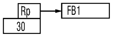
- Decorator nodes are mainly used to decorate function block nodes driven by logic control nodes, for example, can be used to decide whether a branch or even a single node in a behavior tree can be executed.
- Rp, Repeat repeat
- Rt retry
- TO Timeout
- Tm Timer
- negation Iv, Inverter
- FR Force Run
- forced success forced success
- FF Force Failed
- G Guard
- Negative node which can have a child node, used to negate the child node. If the child node fails, it returns success; if the child node succeeds, it returns failure.
- a mandatory failure node which can have a child node (such as a function block node), regardless of whether its child node is successful or not, the node will always return failure.
- a repeated node which may have a child node (such as a function block node), can repeatedly execute its child node for a fixed number of times.
- a retry node which can have a child node (such as a function block node), can trigger its child node up to N times, if its child node returns failure, retry and the number of times will be reduced by one, when the number of retries is zero , returns success; if the child node returns success, break the loop and also return success.
- N is a positive integer.
- a one-time node which may have a child node, means that its child node is only executed once in the workflow, and will not be executed until the workflow is restarted.
- a timeout node which may have a child node, which is used to time the execution time of its child nodes (such as function block nodes), and exit execution when the specified time exceeds (even if the execution is not completed).
- a timer node which may have a child node, executes its child node (such as a function block node) after the specified time is reached.
- a monitoring node which may have at least one child node, and is used to monitor the status of all its child nodes. When any child node executes incorrectly, an error will be reported. When all child nodes are normal, it returns normal.
- a decorator node may also be contained within a flow control node. That is, flow control nodes may include: all or part of main control nodes, logic control nodes, and decorator nodes.
- each behavior tree node can be listed on the graphical user interface in the form of an icon, and the user can determine the node needed to create a workflow by selecting and dragging the icon to add to the canvas.
- the node performs necessary parameter configuration, such as resource configuration and/or input and output parameter configuration.
- the behavior tree corresponding to the workflow can include multiple function block nodes.
- the behavior tree of the corresponding workflow is finally generated by performing corresponding discharge connections on the dragged nodes. That is, the behavior tree construction operation includes adding and connecting nodes of the behavior tree. Further, an operation of associating resources for the added function block nodes may also be included. In addition, it may also include: configuration operations on the input and output parameters of the behavior tree nodes.
- Step S12A in response to the construction operation of the behavior tree, generate a behavior tree corresponding to a workflow, and part or all of the function block nodes in the behavior tree are associated with resources for executing corresponding business operations.
- all function block nodes in the behavior tree need to be associated with resources that perform corresponding business operations; for action flows that do not need to be implemented by on-site resources temporarily, such as simulation work flow, it is not necessary for all function block nodes to be associated with resources for performing corresponding business operations.
- a collaborative robot may not be purchased yet.
- the corresponding general function block node can be used for simulation in advance. When it is confirmed that it is feasible, it can be purchased.
- each behavior tree node may be instantiated in response to the behavior tree construction operation, and a connection relationship between each instantiated behavior tree node may be established.
- some or all of the instantiated function block nodes are associated with resources for executing corresponding business operations. By performing this step, the added function block node can be instantiated as an operation of the corresponding resource. Then, based on the connection relationship between the instantiated behavior tree nodes, a behavior tree corresponding to a workflow is generated.
- the aforementioned behavior tree nodes may be stored in a node library.
- the node library may further include a workflow (WF, WorkFlow) node and a sub-workflow (SWF, SubWorkFlow) node.
- FIG. 2A shows a schematic diagram of constructing a behavior tree of a work unit of a quality inspection production line in an example.
- FIG. 2B to FIG. 2S respectively show schematic diagrams of partial behavior trees constructed in an example. Wherein, the direction of the arrow indicates the execution sequence of the corresponding node.
- the function block nodes can be understood as presented in the form of a label graph, and the construction of this behavior tree based on the function block label graph requires the participation of flow control nodes and even decorator nodes.
- an embodiment of the present invention also provides a method for constructing a behavior tree based on a function block type diagram. In the method, the function block nodes are presented in the form of a type diagram. In practical applications, these two behavior tree construction methods can coexist, and when one of the behavior tree construction methods is used, the other method will also be constructed synchronously.
- FIG. 1D shows an exemplary flow chart of another workflow generation method provided by the embodiment of the present application. As shown in Figure 1D, the method may include the following steps:
- Step S11B receiving the addition and connection operation of the function block node performed by the user on the graphical user interface based on the function block type diagram.
- the type diagram and the label diagram can be understood as two presentation modes of the same function block node, and their functions are both used to realize a corresponding business operation.
- FIG. 2T shows an example of constructing a behavior tree based on the function block nodes of the function block type graph in an example.
- two function block nodes F1, F2 are shown.
- the functional block type diagram may include:
- a function block name 201 used to indicate the type of business operation. For example, screw fastening, image capture, video recording, visual guidance, etc.
- the default function block name will be generated by adding the default name of the function block definition plus the instance number.
- the logical node in the function block node is taken as an example , the names are represented by "logical node 1" and "logical node 2".
- Function block names are editable, but should be unique within the current global workflow.
- the function block header 202 used to indicate the resource for executing the business operation is a torque wrench
- the resource for image collection is a monitor
- the resource for video recording is a monitor
- the resource for visual guidance is a camera.
- the functional block header 202 of a logical node is generally a physical resource, such as "physical node 1" and "physical node 2" as shown in Fig. 2U.
- the resource indicated by the function block header 202 may be pre-associated, or the corresponding resource may be associated through resource configuration after the function block node is added.
- connection operation of the function block nodes may include: a connection operation between the link output port 204 and the link input port 203 between the two function block nodes F1 and F2.
- a link connection 205 is established between the two function block nodes F1 and F2.
- the link connection 205 in this example is a one-way connection used to indicate the running process of the workflow. For example, it can indicate the execution order of the two function block nodes, that is, the function block node F1 on the left is executed first, and then the function block node on the right is executed. F2.
- the connection endpoint is positioned on the link input port 203 .
- the first sensitive area which is called the first sensitive area here
- the second sensitive area which is referred to as the second sensitive area herein, and is used to receive the user's point in the second sensitive area.
- the connection endpoint is positioned on the link output port 204.
- the interconnected function block nodes F1 and F2 in response to the connection operation between the link output port 204 and the link input port 203 between the two function block nodes F1 and F2, can be further An instruction label 207 for indicating the execution order of each function block node is generated, and the instruction label 207 is marked on the function block type diagram of the function block nodes F1 and F2. 1 and 2 as shown in the picture.
- the instruction tag 205 can also be used as an index of jump instructions and as a chapter index of the documentation.
- Input data chunk 208 for representing the set of all data input ports and output data chunk 209 for representing the set of all data output ports.
- the number of data input ports of the function block node can be marked on the input data block 208, such as 5 on the input data block 208 of the function block node F1 and the input data block 208 of the function block node F2 2 above, if the number of data input ports is zero, the input data chunk 208 can be hidden.
- the number of data output ports of the function block node can be marked on the output data block 209, such as 3 on the output data block 209 of the function block node F1 and 1 on the output data block 209 of the function block node F2 , if the number of data output ports is zero, the output data chunk 209 can be hidden.
- each data input port of the function block node can be expanded or hidden by clicking on the input data block 208 .
- Each data output port of the function block node can be expanded or hidden by clicking on the output data block 209 .
- 2U shows a schematic diagram of hiding the data input port of logical node 2 by clicking
- 2V shows a schematic diagram of hiding the data output port of logical node 1 by clicking
- FIG. 2W shows that each data input port is displayed simultaneously.
- a schematic diagram of each data output port FIG. 2X shows a schematic diagram of simultaneously hiding each data input port and each data output port.
- connection operation of the function block nodes may also include: a connection operation between the data output port 211 and the data input port 210 between the corresponding data of the two function block nodes F1 and F2.
- a data connection 212 is established between the two function block nodes F1 and F2.
- Data connection 212 in this example is used to indicate data transmission between two function block nodes F1 and F2.
- a data connection 212 is established between the data output port 211 of the output data 1 of the function block node F1 and the data input port 210 of the input data 2 of the function block node F2, which means that the output of the function block node F1 Data 1 is used as input data 2 of the function block node F2.
- a sensitive area can also be provided within the set range of the data input port 210 output), which is referred to as the third sensitive area here, and is used to locate the connection end point on the data input port 210 when the user's click and connection operations are received in the third sensitive area.
- the third sensitive area there may also be a sensitive area (not shown in the figure) within the setting range of the data output port 211, which is referred to as the fourth sensitive area here, and is used to receive the user's click in the fourth sensitive area.
- the connection endpoint is positioned on the data output port 211 .
- the function block icon 213, specifically, the function block icon 213 may be a vector icon 213, which is used to visually represent the service operation of the function block node.
- the function block icons 213 may also be omitted.
- Function block main body 214 for carrying the above components.
- the adding operation of the function block node may include: dragging and dropping the function block main body 214 .
- Step S12B in response to the addition and connection operations of the function block nodes, construct a behavior tree corresponding to a workflow.
- the behavior tree including the flow control node and the function block node based on the function block label graph in S12A can be constructed synchronously; similarly, in step S12A, the construction includes When the flow control node and the behavior tree of the function block node based on the function block label diagram, the behavior tree based on the function block type diagram in S12B can also be constructed synchronously. And the two behavior tree construction interfaces can be switched according to the user's choice. For example, according to the user's click operation on the behavior tree based on the function block type diagram or the behavior tree based on the function block label diagram, the behavior tree based on the function block type diagram or the function block label diagram based The Behavior Tree toggles the display.
- At least one of the function block nodes in the behavior tree can be further Add and connect at least one data block to each function block node.
- each data block is used to present the corresponding data in the business operation of the function block node connected to it.
- the types of data blocks can include some or all of data pairs, data tables, images, videos, charts, etc.
- Fig. 2Y shows a schematic diagram of adding data blocks to four function block nodes in the behavior tree and displaying corresponding data in each data block in an example of the present application.
- the function block node associated with the monitor to record the production video is added with a type of real-time video data (Live Data -Video) data block;
- the function block node associated with the screw fastening of the torque wrench is added with a data block of type Live Data-Text and a data block of type Live Data-Chart ;
- the function block node of the robot image acquisition associated with the monitor is added with a data block of type Live Data-Image;
- the function block node of the machine vision guide associated with a camera is added with a type of Live Video Data (Live Data-Video) data block.
- each data block may include a data block label 215 for indicating the type of data block and a data block body 216 having a display area for presenting specific data.
- the data block label 215 can be a draggable label, for example, can be moved to any position in the canvas.
- the size of the display area of the data block 216 is adjustable, and is used to display different types of data from the data layer in real time.
- a monitoring link 217 is established between each data block and the corresponding function block node, and one function block can be mapped to multiple data blocks. When the workflow is executed, for example, at runtime, the monitoring and output data corresponding to the function block nodes will be transmitted to the corresponding data blocks for real-time display.
- the data block in this embodiment is a low-code data block, which is different from other SCADA and dashboard systems in that the low-code data block in this embodiment is also a low-code element, which can be used as a part of the behavior tree, and all of its Properties can all be managed in low-code logic.
- the data source in the low-code data block comes from the data layer, which can obtain data through the interface provided by the data layer at runtime or in the cloud execution engine.
- the data source can be a time series database, RDBMS or NoSQL.
- Low-code data block is a flexible, scalable and adaptable system that can be applied to any functional block node that can be associated with physical devices.
- the data blocks used to implement data monitoring can be considered as the visual interface of the data layer.
- At least one of the function block nodes in the behavior tree can be further Add and connect at least one data block to each function block node.
- each data block is used to present the corresponding data in the business operation of the function block node connected to it.
- the types of data blocks can include some or all of data pairs, data tables, images, videos, charts, etc.
- FIG. 2Y shows a schematic diagram of adding data blocks to four function block nodes in the behavior tree and displaying corresponding data in each data block in an example of the present application.
- the function block node associated with the monitor to record the production video is added with a type of real-time video data (Live Data -Video) data block;
- the function block node associated with the screw fastening of the torque wrench is added with a data block of type Live Data-Text and a data block of type Live Data-Chart ;
- the function block node of the robot image acquisition associated with the monitor is added with a data block of type Live Data-Image;
- the function block node of the machine vision guide associated with a camera is added with a type of Live Video Data (Live Data-Video) data block.
- each data block may include a data block label 215 for indicating the type of data block and a data block body 216 having a display area for presenting specific data.
- the data block label 215 can be a draggable label, for example, can be moved to any position in the canvas.
- the size of the display area of the data block 216 is adjustable, and is used to display different types of data from the data layer in real time.
- a monitoring link 217 is established between each data block and the corresponding function block node, and one function block can be mapped to multiple data blocks. When the workflow is executed, for example, at runtime, the monitoring and output data corresponding to the function block nodes will be transmitted to the corresponding data blocks for real-time display.
- the data block in this embodiment is a low-code data block, which is different from other SCADA and dashboard systems in that the low-code data block in this embodiment is also a low-code element, which can be used as a part of the behavior tree, and all of its Properties can all be managed in low-code logic.
- the data source in the low-code data block comes from the data layer, which can obtain data through the interface provided by the data layer at runtime or in the cloud execution engine.
- the data source can be a time series database, RDBMS or NoSQL.
- Low-code data block is a flexible, scalable and adaptable system that can be applied to any functional block node that can be associated with physical devices.
- the data blocks used to implement data monitoring can be considered as the visual interface of the data layer.
- this embodiment may further include the following step S13 as shown by the dotted line in FIG. 1A and FIG. 1B .
- Step S13 analyzing the behavior tree, deploying the workflow corresponding to the behavior tree to the runtime of the corresponding work unit, so that the runtime executes the workflow to control the workflow in the work unit
- Each resource executes business operations according to the workflow.
- the runtime may further provide corresponding data obtained during the execution of the business operation to the corresponding data block for display.
- the corresponding data acquired during the execution of business operations may be directly provided to the corresponding data block for display or provided to the corresponding data block through a third-party device for display at runtime.
- the work unit may have a main controller, and in this case, the runtime may be located on the work unit's main controller.
- the equipment resources in the resources can be connected to the main controller, and the main controller can control the equipment resources connected to it to perform corresponding business operations according to the runtime workflow; the human resources in the resources can be directly based on The workflow at runtime prompts for the appropriate action.
- the behavior tree can be stored in a Markup markup language such as XML (Extensible Markup Language), and can be verified by an XML Schema (XSD) prototype to verify that the XML format of the behavior tree is correct.
- XML Extensible Markup Language
- XSD XML Schema
- the OT domain usually refers to operational technology (Operational Technology, OT), which integrates hardware and software, and detects or triggers processes in the enterprise by directly monitoring and/or controlling physical devices (called OT devices). changes or events.
- OT utilizes computers to monitor or change physical conditions such as industrial control systems (Industrial Control System, ICS).
- ICS Industrial Control System
- the industrial control system is based on computer-implemented facilities, systems, and equipment for remote monitoring and/or control of key industrial processes to achieve physical functions.
- the word "OT” is used to distinguish industrial control systems from traditional information technology (Information Technology, IT) systems in terms of technical implementation and functions.
- the above workflow generation method in this embodiment can be used in this OT domain as a low-code development method in the OT domain.
- the workflow generation method shown in Figure 1A can be implemented in the OT domain, such as an OT domain low-code development platform, and correspondingly, the workflow can be an OT domain workflow; the work unit can be an OT domain A working unit; the device may be an OT device.
- OT devices may include, but are not limited to: Internet of Things (IoT) devices, Programmable Logic Controllers (PLC), Robotics, Manual Process, Industrial Computers (Industrial Personal Computer, IPC) and so on.
- the above workflow generation method in this embodiment can be used in this ITOT system as a low-code development method in the OT domain that can be integrated with the IT domain.
- the workflow generation method shown in Figure 1A can be implemented in the OT domain, such as an OT domain low-code development platform, and correspondingly, the workflow can be an OT domain workflow; the work unit can be a work in the OT domain unit.
- the IT equipment can call the microservice directly or through a knowledge center.
- the corresponding data obtained during the execution of the business operation may be provided to the corresponding data block through the microservice for display at runtime.
- the corresponding data obtained during the execution of business operations may be provided to the knowledge center during runtime, and the knowledge center shall process the data including filtering, and then directly provide or pass through the microservice Provided to the corresponding data block for display.
- an API of the microservice may be generated based on the behavior tree.
- the processing procedure in the API includes each operation in the OT domain workflow
- the input parameter of the API is the parameter obtained from the input port of the OT domain workflow
- the output parameter of the API is the Parameters output by the output port of the OT domain workflow.
- the specific implementation methods include but are not limited to the following two:
- the code developers in the OT domain can notify the code developers in the IT domain of the names and IP addresses of the generated microservices. In this way, the code developers in the IT domain can directly assign the The information is written into the code, so that the IT equipment can call the microservice.
- Method 1 is more suitable for scenarios with a small number of microservices.
- each microservice is registered on the knowledge center platform, so that an IT domain code development tool realizes that IT equipment discovers the connected microservices through the knowledge center platform.
- an IT domain code development tool can be used to realize the connected microservices discovered by the IT domain equipment through the knowledge center through code development.
- the device that completes microservice registration can be an OT domain microservice generator or a third-party device.
- the third-party device can be regarded as a part of the OT domain low-code development platform, or implemented in the knowledge center platform.
- Method 2 is more suitable for scenarios with a large number of microservices.
- IT equipment may include, but not limited to: Manufacturing Operation Management (MOM) system, Manufacturing Execution System (MES), Enterprise Resource Planning (Enterprise Resource Planning, ERP) system, enterprise service Bus (Enterprise Service Bus, ERP), Product Lifecycle Management (Product Lifecycle Management, PLM) system, etc.
- MOM Manufacturing Operation Management
- MES Manufacturing Execution System
- ERP Enterprise Resource Planning
- ERP enterprise Resource Planning
- ERP enterprise Service Bus
- PLM Product Lifecycle Management
- the IT domain code development tool can be programmed to realize that IT equipment invokes microservices through a knowledge platform to trigger the runtime execution of the OT domain workflow of the main controller of the work unit, thereby realizing the code development of the IT domain
- the platform controls the process of the OT domain, which realizes the integration of the IT domain and the OT domain.
- the microservice is automatically generated by the OT domain microservice generator based on the OT domain behavior tree. It is not necessary for the code development tools of the IT domain to understand the details of the OT domain workflow. It only needs to obtain the identification (such as: name) and IP address of the microservice That is, developers in the IT domain do not need to understand OT domain devices and control processes, and are easy to implement and understand.
- the applicable fields of the embodiments of the present application include but are not limited to: Industrial Automation, Logistics, Laboratory, Maritime, Smart Grid, Electric Vehicle Infrastructure Vehicle Infrastructure), Electric Vehicle, Building Automation, Smart City, Water Treatment, Garbage Recycling and Smart Farm, etc.
- the workflow generation method in the embodiment of the present application has been described in detail above, and the workflow generation system in the embodiment of the present application will be described in detail below.
- the workflow generation system in the embodiment of the present application can be used to implement the workflow generation method in the embodiment of the present application.
- For the details not disclosed in the system embodiment of the present invention please refer to the corresponding description in the method embodiment of the present invention, here I won't repeat them one by one.
- Fig. 3 shows a schematic structural diagram of a workflow generation system in an embodiment of the present application.
- the system may include: a node library 110 , a graphical interface module 120 and an editing processing module 130 .
- the node library 110 is provided with behavior tree nodes for constructing behavior trees; the behavior tree nodes may include: flow control nodes and function block nodes.
- a behavior tree is used to represent a workflow, and the workflow is used to define an operation to be performed by a work unit.
- the flow control node is used to realize the logic control in the workflow;
- the function block node is used to realize the business operation in the workflow, and
- the function block node may include: logic nodes, each logic node corresponds to an operation template, each The operation template predefines at least one type of operations that can be performed by resources such as equipment, and the operations include actions, methods or skills.
- the node library 110 may further include various types of data blocks, and each data block is used to present corresponding data in the business operations of the function block nodes connected thereto.
- the types of the data blocks include: some or all of data types such as data pairs, data tables, images, videos, and graphs.
- the resources are represented in the form of resource nodes, and all resource nodes are associated and stored in the form of a resource knowledge graph;
- the resource knowledge graph includes: each resource node, and a connection representing the relationship between the resource nodes.
- this embodiment may further include: a resource library 150, configured to store various resources in the form of a resource knowledge graph, and each resource can perform at least one business operation.
- the flow control node may include: some or all of the main control node, logic control node and condition node; the main control node may include: a start node, an end node, a go node, a key node , stop node, abort some or all of the nodes.
- the logic control nodes include: some or all of sequence nodes, reactive sequence nodes, parallel nodes, intra-process quality control nodes, priority nodes, reactive priority nodes, condition judgment nodes, and multi-branch selection nodes.
- the function block nodes may further include: some or all of manual nodes, dynamic nodes, delay nodes, and idle nodes.
- the behavior tree node further includes: a decorator node, which may include: a repeat node, a retry node, a one-off node, a timeout node, a timer node, a negate node, a forced run node, and a forced success Some or all of nodes, force-fail nodes, and monitor nodes.
- a decorator node which may include: a repeat node, a retry node, a one-off node, a timeout node, a timer node, a negate node, a forced run node, and a forced success
- some or all of the function block nodes in the node library 110 are respectively bound with resources for executing the service operations corresponding to the function block nodes.
- the function block nodes in the node library 110 can be presented in the form of label diagrams as shown in Figures 2A to 2T, or in the form of type diagrams in Figures 2T to 2X .
- the function block nodes in the node library 110 may also only be presented in the form of a type diagram.
- the specific structure of the function block node in the form of a function block type graph may be shown in FIG. 2T . I won't repeat them here.
- the graphical interface module 120 is configured to provide a graphical user interface GUI for the user to perform behavior tree building operations based on the behavior tree nodes in the node library. In addition, adding and connecting data blocks can also be performed on the graphical user interface GUI.
- the graphical user interface may include a first graphical user interface for constructing a behavior tree based on a flow control node and a function block node in the form of a function block label graph, and a second graph for constructing a behavior tree based on a function block node in the form of a function block type diagram user interface, and the two graphical user interfaces can be switched and displayed according to the user's selection.
- the behavior tree construction operation may include adding function block nodes and connecting operations.
- the adding operation of the function block node may include: a drag operation on the main body of the function block; the connection operation of the function block node may include: between two function block nodes The connection operation between the link output port and the link input port, and the connection operation between the data output port and the data input port between the corresponding data of two function block nodes.
- each behavior tree node can be listed on the graphical user interface GUI in the form of an icon.
- the editing processing module 130 is configured to generate a behavior tree corresponding to a workflow in response to the construction operation of the behavior tree.
- the editing processing module 130 is further configured to add and connect at least one data block for each function block node in the at least one function block node in the behavior tree in response to the adding and connecting operation of the data block.
- the editing processing module 130 may respond to the behavior tree construction operation, instantiate each behavior tree node, and establish a connection relationship between each instantiated behavior tree node; based on the The connection relationship between the instantiated behavior tree nodes generates a behavior tree corresponding to a workflow.
- some or all of the instantiated function block nodes are associated with resources for executing corresponding business operations. For example, through this operation, a logical node is instantiated as an operation corresponding to a resource such as a device.
- each behavior tree node and each data block can be listed on the graphical user interface in the form of an icon, and the user can determine the node needed to create the workflow by selecting and dragging the icon to add to the canvas, and further , and also perform necessary parameter configuration on the node, such as resource configuration and/or input/output parameter configuration.
- the behavior tree corresponding to the workflow can include multiple logical nodes. Determine the execution sequence between logical nodes, and finally generate a behavior tree corresponding to the workflow by making corresponding discharge connections to the dragged nodes.
- the behavior tree construction operation may include: an operation of adding a function block node and associating a resource for the added function block node.
- the workflow generation system in this embodiment may further include: a parsing and deployment module 140 configured to parse the behavior tree, and deploy the workflow corresponding to the behavior tree to the corresponding The runtime of the work unit, so that the runtime executes the workflow to control each resource in the work unit to perform business operations according to the workflow.
- the corresponding data acquired during the execution of the business operation may be provided to the corresponding data block for display.
- the worker unit may have a master controller, in which case the runtime may reside on the master controller of the worker unit.
- the equipment resources in the resources can be connected to the main controller, and the main controller can control the equipment resources connected to it to perform corresponding operations according to the runtime workflow; the human resources in the resources can be directly based on the running The workflow at the time prompts you to perform the appropriate action.
- the work unit may have a main controller, and in this case, the runtime may be located on the work unit's main controller.
- the equipment resources in the resources can be connected to the main controller, and the main controller can control the equipment resources connected to it to perform corresponding operations according to the runtime workflow; the human resources in the resources can be directly based on the running The workflow at the time prompts you to perform the appropriate action.
- FIG. 4A shows an OT domain low-code development platform 100 provided by an embodiment of the present application, and the platform 100 can be used to implement the workflow generation system shown in FIG. 3 .
- the OT domain low-code development platform 100 may include:
- An OT domain low-code development tool 10 the OT domain low-code development tool 10 can be configured to implement the graphical interface module 120 and the editing processing module 130 in the workflow generation system shown in FIG.
- the parse deployment module 140 in the workflow generation system is shown.
- the node library 110 and the resource library 150 in the workflow generation system shown in FIG. 3 can be stored in a memory.
- the OT domain low-code development platform 100 may also include the runtime 30 of the main controller of the above-mentioned working unit.
- the OT domain low-code development tool 10 can deploy the OT domain workflow corresponding to the generated behavior tree to the runtime 30 of the main controller of the work unit, so that the runtime 30 executes the workflow to control the workflow connected to the Each OT resource such as an OT device in the work unit on the main controller executes an operation according to the OT domain workflow.
- the composition of the OT domain low-code development platform 100 shown in FIG. 4A and FIG. 4B only involves the OT domain.
- the integration of the IT domain and the OT domain has become increasingly important for the digital transformation of enterprises. What needs to be realized is how the enterprise can control the processes in the OT domain in an understandable and non-IT programming way.
- the OT domain low-code development platform 100 shown in FIG. 4C solves how to control the flow of the OT domain through the code development platform 300 of the IT domain.
- the OT domain low-code development platform 100 may further include an OT domain microservice generator 20 , which can generate microservices 40 based on the OT domain behavior tree.
- the IT domain code development tool 301 can be programmed to enable the IT device to call the microservice 40 through a knowledge center 200 to trigger the runtime 30 of the main controller of the work unit to execute the OT domain workflow.
- the code development platform 300 of the IT domain can control the process of the OT domain, that is, the integration of the IT domain and the OT domain is realized.
- the microservice 40 is automatically generated by the OT domain microservice generator 20 based on the OT domain behavior tree. It is not necessary for the code development tool 301 in the IT domain to understand the details of the OT domain workflow. It only needs to obtain the identification of the microservice 40 (for example: name ) and IP address, it is not necessary for IT domain developers to understand OT domain devices and control processes, and it is easy to implement and understand.
- the code developers in the OT domain can notify the code developers in the IT domain of the names and IP addresses of the generated microservices 40, so that the code developers in the IT domain can directly assign the microservices 40 to The information of 40 is written into the code, so as to implement the call of the IT equipment to the microservice 40.
- Method 1 is more suitable for scenarios with a small number of microservices.
- each microservice 40 can be registered on the knowledge center 200 , so that the IT domain code development tool 301 can realize the connected microservice 40 through the knowledge center 200 by the IT domain equipment through code development.
- the device for completing the registration of the microservice 40 may be the OT domain microservice generator 20 or a third-party device 50 as shown in FIG. 4D .
- the third-party device 50 can be regarded as a part of the low-code development platform 100 in the OT domain, or implemented in the knowledge center 200 .
- Method 2 is more suitable for scenarios with a large number of microservices. By registering microservices on the knowledge center platform, it is more effective to realize the calling of microservices by IT equipment, and strengthen the integration of OT domain and IT domain.
- the OT domain microservice generator 20 can generate the API of the microservice 40 based on the OT domain behavior tree, wherein, the processing procedure in the API can include the operation of each functional block in the OT domain workflow, and the input parameter of the API is OT
- the parameters obtained by the input port of the domain workflow, and the output parameters of the API are the parameters output by the output port of the OT domain workflow.
- FIG. 4E An application scenario of the OT domain low-code development platform 100 provided in the embodiment of the present application in the field of industrial automation is shown in FIG. 4E .
- the low-code development tool 10 generates a behavior tree corresponding to the OT domain workflow under the operation of the user, and the OT domain workflow defines the operations to be performed by the production line as a work unit shown on the right side of FIG. 4E .
- the corresponding workflow is generated and published to the runtime 30, so that the runtime 30 controls the completion of the production line operation of the work unit; at the same time, the corresponding microservice can be generated by the microservice generator 20 based on the behavior tree and registered in The knowledge center 200, so that the code development tool 301 in the IT domain can call the corresponding microservice through the knowledge center 200.
- the user can edit each node including the function block node by dragging and dropping to edit the behavior tree of the OT domain. Data (for example: workpiece processing parameters), control the operation of the entire work unit.
- the working unit here is a production line, which includes machines, conveyor belts, robotic arms, people, PLC, AGB, etc.
- the code development tool 301 of the IT domain can also be located on the same hardware device as the low-code development tool 10 , for example, on the same computer.
- FIG. 5 shows a schematic structural diagram of another workflow generation system provided by the embodiment of the present application.
- the system can be used to implement the method shown in Fig. 1A, or realize the workflow generation system shown in Fig. 3, or realize the workflow generation system described in any one of Fig. 4A to Fig. 4D , that is, the low-code development platform 100 in the OT domain.
- the aforementioned OT domain low-code development tool 10, OT domain microservice generator 20, runtime 30, and third-party device 60 can all be implemented as individual hardware devices, such as servers, workstations, single-chip microcomputers or processing chips.
- these devices are implemented on the same hardware device, which is stored in at least one memory as a software program, and is called by at least one processor to implement the aforementioned OT domain low-code development method.
- the node library 110 and each generated microservice 40 may be stored in at least one memory.
- the system may include: at least one memory 51 , at least one processor 52 and at least one display 53 .
- some other components may also be included, such as a communication port (not shown in FIG. 5 ) and the like. These components communicate via bus 54 .
- At least one memory 51 is used to store computer programs.
- At least one memory 51 may include computer readable media such as random access memory (RAM).
- at least one memory 51 can also store an operating system and the like.
- the operating system includes but is not limited to: Android operating system, Symbian operating system, Windows operating system, Linux operating system and so on.
- the above computer stored program may include the following program modules: node library 110, graphical interface module 120, editing and processing module 130, parsing and deployment module 140, optionally, may also include OT domain microservice generator 20, runtime 30, third-party device 50.
- At least one processor 52 is configured to invoke a computer program stored in at least one memory 51 to execute the workflow generation method described in the embodiment of the present application.
- At least one processor 52 may be a microprocessor, an application specific integrated circuit (ASIC), a digital signal processor (DSP), a central processing unit (CPU), a graphics processing unit (GPU), a state machine, or the like. It can receive and send data through the communication port.
- ASIC application specific integrated circuit
- DSP digital signal processor
- CPU central processing unit
- GPU graphics processing unit
- state machine or the like. It can receive and send data through the communication port.
- At least one display 53 is used to display a graphical user interface.
- At least one processor 52 is configured to invoke a computer program stored in at least one memory 51 to enable the system to execute the operations in the workflow generation method in any of the foregoing implementation manners.
- the communication interface is used to implement communication with other devices, such as communication with the knowledge center 200 .
- the OT domain low-code development tool 10 used to implement the graphical interface module 120, the editing processing module 130, and the parsing and deployment module 140 can be a lightweight web-based application program, which can be used in industrial sites (such as edge device or local server), or in the cloud (public cloud such as AWS or private cloud such as OpenStack). Its visual engineering paradigm is derived from the Function Block Typed Diagram (FBTD).
- FBTD Function Block Typed Diagram
- the OT domain microservice generator 20 can use modern translation programming languages to generate standard APIs such as RESTful or RPC.
- Runtime 30 can easily implement OT domain workflow and provide openness based on the ecosystem of open source communities (such as Python).
- the runtime 30 can be deployed on an embedded IoT device such as a single board computer (Single Board Computer, SBC).
- the embodiment of the present application may include an apparatus having an architecture different from that shown in FIG. 5 .
- the above architecture is only exemplary, and is used to explain the workflow construction method provided by the embodiment of the present application.
- the embodiment of the present application also provides an IT domain OT domain integration system, that is, an ITOT system, which may include IT equipment and the workflow generation system in any implementation manner of the present application.
- an ITOT system which may include IT equipment and the workflow generation system in any implementation manner of the present application.
- it may further include: a code development platform 300 in the IT domain as shown in FIG. 4C and FIG. 4D .
- the embodiment of the present application also provides a computer-readable storage medium, the computer-readable storage medium stores computer-readable codes, and when the computer-readable codes are executed by the processor, the processor executes the aforementioned workflow construction method.
- an embodiment of the present application further provides a computer program product, the computer program product is tangibly stored on a computer-readable medium and includes computer-readable instructions, and when executed, the computer-readable instructions cause at least one processing The controller executes the steps in the workflow generation method in the embodiment of the present application.
- a system or device equipped with a storage medium may be provided, on which computer-readable codes for realizing the functions of any implementation manner in the above-mentioned embodiments are stored, and the computer (or CPU or The MPU) reads and executes the computer readable codes stored in the storage medium.
- the computer or CPU or The MPU
- some or all of the actual operations can also be completed by an operating system or the like operating on the computer through instructions based on computer readable codes.
- examples of computer-readable media include, but are not limited to, floppy disks, CD-ROMs, magnetic disks, optical disks (such as CD-ROM, CD-R, CD-RW, DVD-ROM, DVD-RAM, DVD-RW , DVD+RW), memory chips, ROM, RAM, ASIC, configured processor, all-optical media, all tape or other magnetic media, or any other media from which a computer processor can read instructions.
- various other forms of computer-readable media can transmit or carry instructions to the computer, including routers, private or public networks, or other wired and wireless transmission devices or channels, such as downloading from a server computer or cloud by a communication network computer readable instructions. Instructions may include code in any computer programming language, including C, C++, C++, Visual Basic, java, and JavaScript.
Landscapes
- Engineering & Computer Science (AREA)
- Theoretical Computer Science (AREA)
- Business, Economics & Management (AREA)
- Software Systems (AREA)
- Physics & Mathematics (AREA)
- General Physics & Mathematics (AREA)
- Entrepreneurship & Innovation (AREA)
- Human Resources & Organizations (AREA)
- Economics (AREA)
- Strategic Management (AREA)
- General Engineering & Computer Science (AREA)
- Game Theory and Decision Science (AREA)
- Development Economics (AREA)
- Educational Administration (AREA)
- Marketing (AREA)
- Operations Research (AREA)
- Quality & Reliability (AREA)
- Tourism & Hospitality (AREA)
- General Business, Economics & Management (AREA)
- Management, Administration, Business Operations System, And Electronic Commerce (AREA)
Abstract
Description
Claims (14)
- 工作流生成方法,其特征在于,包括:接收用户在图形用户界面上进行的行为树构建操作,所述行为树构建操作包括对包括功能块节点在内的行为树节点的添加及连线操作;其中,一个行为树用于表征一个工作单元中各资源要执行的业务操作的工作流;所述功能块节点用于实现工作流中的业务操作;响应于所述行为树构建操作,将各个行为树节点实例化,并建立各个实例化的行为树节点之间的连接关系;其中,实例化的功能块节点中的部分或全部关联有执行对应业务操作的资源;基于所述实例化的行为树节点之间的连接关系,生成对应一工作流的行为树。
- 根据权利要求1所述的工作流生成方法,其特征在于,接收用户在图形用户界面上进行的行为树构建操作之前,进一步包括:预先为部分或全部功能块节点分别关联执行所述功能块节点对应的业务操作的资源。
- 根据权利要求1所述的工作流生成方法,其特征在于,所述行为树构建操作进一步包括:为所添加的功能块节点关联资源的操作。
- 根据权利要求2或3所述的工作流生成方法,其特征在于,所述资源以资源节点的形式表示,且所有资源节点以资源知识图谱的形式关联存储;所述资源知识图谱包括:各个资源节点,以及表示资源节点间关系的连线。
- 根据权利要求1至4中任一项所述的工作流生成方法,其特征在于,进一步包括:对所述行为树进行解析,将所述行为树对应的工作流部署到对应的工作单元的运行时上,以使得所述工作单元中的各个资源按照所述工作流执行操作。
- 根据权利要求5所述的工作流生成方法,其特征在于,所述工作流为OT域工作流;所述工作单元为OT域内的工作单元;所述资源包括OT设备。
- 工作流生成系统,其特征在于,包括:节点库(110),其中设置有用于构建行为树的行为树节点;所述行为树节点包括:功能块节点;其中,一个行为树用于表征一个工作单元中各资源要执行的业务操作的工作流;所述功能块节点用于实现工作流中的业务操作;图形界面模块(120),被配置为提供用户进行行为树构建操作的图形用户界面,所述行为树构建操作包括对包括功能块节点在内的行为树节点的添加及连线操作;编辑处理模块(130),被配置为响应于所述行为树构建操作,将各个行为树节点实例化,并建立各个实例化的行为树节点之间的连接关系;其中,实例化的功能块节点中的部分或全部关联有执行对应业务操作的资源;基于所述实例化的行为树节点之间的连接关系,生成对应一工作流的行为树。
- 根据权利要求7所述的工作流生成系统,其特征在于,进一步包括:资源库(150),用于以资源知识图谱的形式存储各个资源,每个资源能够执行至少一种业务操作;所述资源知识图谱包括:表示各个资源的节点,以及表示节点间关系的连线。
- 根据权利要求8所述的工作流生成系统,其特征在于,所述资源库(150)中的每个资源分别关联有所述节点库(110)中的一个功能块节点。
- 根据权利要求7至9中任一项所述的工作流生成系统,其特征在于,进一步包括:解析部署模块(140),被配置为解析所述行为树,将所述行为树对应的工作流部署到对应的工作单元的运行时(30)上,以使得所述工作单元中的各个资源按照所述工作流执行操作。
- 一种工作流生成系统,其特征在于,包括:至少一个存储器(51),被配置为存储计算机可读代码;至少一个处理器(52),被配置为调用所述计算机可读代码,执行如权利要求1~6中任一项所述的工作流生成方法中的步骤。
- 一种IT域OT域融合系统,其特征在于,包括:IT设备;和如权利要求7至11中任一项所述的工作流生成系统;其中,所述工作流为OT域工作流;所述工作单元为OT域内的工作单元;所述资源为OT资源;且所述工作流生成系统进一步包括:OT域微服务生成器(20),用于基于所述行为树生成一个微服务(40),以使得所述IT设备通过调用所述微服务(40)而触发所述工作单元的运行时(30)执行所述OT域工作流。
- 一种计算机可读介质,其特征在于,所述计算机可读介质上存储有计算机可读指令,所述计算机可读指令在被处理器执行时,使所述处理器执行如权利要求1~6中任一项所述的工作流生成方法中的步骤。
- 一种计算机程序产品,其特征在于,所述计算机程序产品被有形地存储在计算机可读介质上并且包括计算机可读指令,所述计算机可读指令在被执行时使至少一个处理器执行根据权利要求1~6中任一项所述的工作流生成方法中的步骤。
Priority Applications (4)
| Application Number | Priority Date | Filing Date | Title |
|---|---|---|---|
| PCT/CN2022/075059 WO2023142062A1 (zh) | 2022-01-29 | 2022-01-29 | 工作流生成方法、系统、介质及程序产品 |
| EP22922892.9A EP4459525A1 (en) | 2022-01-29 | 2022-01-29 | Workflow generation method and system, and medium and program product |
| CN202280089272.6A CN118556241A (zh) | 2022-01-29 | 2022-01-29 | 工作流生成方法、系统、介质及程序产品 |
| US18/832,602 US20250165305A1 (en) | 2022-01-29 | 2022-01-29 | Workflow Generation Method and System |
Applications Claiming Priority (1)
| Application Number | Priority Date | Filing Date | Title |
|---|---|---|---|
| PCT/CN2022/075059 WO2023142062A1 (zh) | 2022-01-29 | 2022-01-29 | 工作流生成方法、系统、介质及程序产品 |
Publications (1)
| Publication Number | Publication Date |
|---|---|
| WO2023142062A1 true WO2023142062A1 (zh) | 2023-08-03 |
Family
ID=87470198
Family Applications (1)
| Application Number | Title | Priority Date | Filing Date |
|---|---|---|---|
| PCT/CN2022/075059 WO2023142062A1 (zh) | 2022-01-29 | 2022-01-29 | 工作流生成方法、系统、介质及程序产品 |
Country Status (4)
| Country | Link |
|---|---|
| US (1) | US20250165305A1 (zh) |
| EP (1) | EP4459525A1 (zh) |
| CN (1) | CN118556241A (zh) |
| WO (1) | WO2023142062A1 (zh) |
Cited By (4)
| Publication number | Priority date | Publication date | Assignee | Title |
|---|---|---|---|---|
| CN116993233A (zh) * | 2023-09-28 | 2023-11-03 | 南通华隆微电子股份有限公司 | 一种提高二极管封装质量的方法与系统 |
| CN117132246A (zh) * | 2023-10-27 | 2023-11-28 | 安联奇智(安徽)科技有限公司 | 柔性生产线的能耗统计系统、方法、设备和介质 |
| CN118250288A (zh) * | 2024-05-24 | 2024-06-25 | 杭州宇泛智能科技股份有限公司 | 基于场景组件化的AIoT中台数据处理方法、装置及系统 |
| CN119106544A (zh) * | 2024-08-15 | 2024-12-10 | 北京方州科技有限公司 | 一种基于行为树的仿真模型行为实现方法及装置 |
Citations (3)
| Publication number | Priority date | Publication date | Assignee | Title |
|---|---|---|---|---|
| CN109933010A (zh) * | 2017-12-15 | 2019-06-25 | 中国科学院沈阳自动化研究所 | 一种面向个性化定制的工业cps系统和实现方法 |
| EP3614319A1 (en) * | 2018-08-20 | 2020-02-26 | Siemens Aktiengesellschaft | Tracking execution of an industrial workflow of a petri net |
| CN111723176A (zh) * | 2019-03-18 | 2020-09-29 | 西门子股份公司 | 一种用于生成合成交互的语义描述的方法 |
-
2022
- 2022-01-29 CN CN202280089272.6A patent/CN118556241A/zh active Pending
- 2022-01-29 US US18/832,602 patent/US20250165305A1/en active Pending
- 2022-01-29 EP EP22922892.9A patent/EP4459525A1/en active Pending
- 2022-01-29 WO PCT/CN2022/075059 patent/WO2023142062A1/zh active Application Filing
Patent Citations (3)
| Publication number | Priority date | Publication date | Assignee | Title |
|---|---|---|---|---|
| CN109933010A (zh) * | 2017-12-15 | 2019-06-25 | 中国科学院沈阳自动化研究所 | 一种面向个性化定制的工业cps系统和实现方法 |
| EP3614319A1 (en) * | 2018-08-20 | 2020-02-26 | Siemens Aktiengesellschaft | Tracking execution of an industrial workflow of a petri net |
| CN111723176A (zh) * | 2019-03-18 | 2020-09-29 | 西门子股份公司 | 一种用于生成合成交互的语义描述的方法 |
Cited By (6)
| Publication number | Priority date | Publication date | Assignee | Title |
|---|---|---|---|---|
| CN116993233A (zh) * | 2023-09-28 | 2023-11-03 | 南通华隆微电子股份有限公司 | 一种提高二极管封装质量的方法与系统 |
| CN116993233B (zh) * | 2023-09-28 | 2023-12-12 | 南通华隆微电子股份有限公司 | 一种提高二极管封装质量的方法与系统 |
| CN117132246A (zh) * | 2023-10-27 | 2023-11-28 | 安联奇智(安徽)科技有限公司 | 柔性生产线的能耗统计系统、方法、设备和介质 |
| CN117132246B (zh) * | 2023-10-27 | 2024-02-06 | 安联奇智(安徽)科技有限公司 | 柔性生产线的能耗统计系统、方法、设备和介质 |
| CN118250288A (zh) * | 2024-05-24 | 2024-06-25 | 杭州宇泛智能科技股份有限公司 | 基于场景组件化的AIoT中台数据处理方法、装置及系统 |
| CN119106544A (zh) * | 2024-08-15 | 2024-12-10 | 北京方州科技有限公司 | 一种基于行为树的仿真模型行为实现方法及装置 |
Also Published As
| Publication number | Publication date |
|---|---|
| EP4459525A1 (en) | 2024-11-06 |
| US20250165305A1 (en) | 2025-05-22 |
| CN118556241A (zh) | 2024-08-27 |
Similar Documents
| Publication | Publication Date | Title |
|---|---|---|
| WO2023142062A1 (zh) | 工作流生成方法、系统、介质及程序产品 | |
| WO2023164841A1 (zh) | 工作流执行方法、装置、存储介质及程序产品 | |
| WO2023004805A1 (zh) | 工作流建模实施系统、方法及存储介质 | |
| WO2023142076A1 (zh) | 工作流控制方法、装置、系统、介质及程序产品 | |
| WO2023004806A1 (zh) | Ai模型的设备部署方法、系统及存储介质 | |
| Fend et al. | CPSAML: A language and code generation framework for digital twin based monitoring of mobile cyber-physical systems | |
| WO2023142079A1 (zh) | 工作流创建方法、系统、介质及程序产品 | |
| EP4462299A1 (en) | Dynamic workflow implementation method and system, medium, and program product | |
| EP4459398A1 (en) | Workflow generation method, device and system, medium, and program product | |
| WO2023142078A1 (zh) | 工作流构建方法、系统、介质及程序产品 | |
| WO2023142066A1 (zh) | 工作流构建及监控方法、系统、介质及程序产品 | |
| EP4471687A1 (en) | Workflow execution method and system, medium, and program product | |
| EP4459470A1 (en) | Workflow generation method, device and system, medium, and program product | |
| WO2023164835A1 (zh) | 工作流执行方法、装置、存储介质及程序产品 | |
| Yu et al. | The implementation of IEC60870-5-104 based on UML statechart and Qt state machine framework | |
| WO2023142075A1 (zh) | 工作流创建方法、装置、平台和计算机可读介质 | |
| EP4495824A1 (en) | Conversion method and apparatus for natural language sentence, and storage medium | |
| CN118860574A (zh) | 一种ai实现自动工作流执行的装置及方法 | |
| Plasch | Model-based generation of an IEC 61499 control application for a flexible robot system |
Legal Events
| Date | Code | Title | Description |
|---|---|---|---|
| 121 | Ep: the epo has been informed by wipo that ep was designated in this application |
Ref document number: 22922892 Country of ref document: EP Kind code of ref document: A1 |
|
| WWE | Wipo information: entry into national phase |
Ref document number: 202280089272.6 Country of ref document: CN |
|
| WWE | Wipo information: entry into national phase |
Ref document number: 18832602 Country of ref document: US |
|
| ENP | Entry into the national phase |
Ref document number: 2022922892 Country of ref document: EP Effective date: 20240729 |
|
| NENP | Non-entry into the national phase |
Ref country code: DE |
|
| WWP | Wipo information: published in national office |
Ref document number: 18832602 Country of ref document: US |