WO2023136134A1 - 信号処理装置および信号処理方法、並びにプログラム - Google Patents
信号処理装置および信号処理方法、並びにプログラム Download PDFInfo
- Publication number
- WO2023136134A1 WO2023136134A1 PCT/JP2022/048173 JP2022048173W WO2023136134A1 WO 2023136134 A1 WO2023136134 A1 WO 2023136134A1 JP 2022048173 W JP2022048173 W JP 2022048173W WO 2023136134 A1 WO2023136134 A1 WO 2023136134A1
- Authority
- WO
- WIPO (PCT)
- Prior art keywords
- pixel
- value
- raw signal
- signal
- saturation determination
- Prior art date
- Legal status (The legal status is an assumption and is not a legal conclusion. Google has not performed a legal analysis and makes no representation as to the accuracy of the status listed.)
- Ceased
Links
Images





Classifications
-
- H—ELECTRICITY
- H04—ELECTRIC COMMUNICATION TECHNIQUE
- H04N—PICTORIAL COMMUNICATION, e.g. TELEVISION
- H04N25/00—Circuitry of solid-state image sensors [SSIS]; Control thereof
- H04N25/50—Control of the SSIS exposure
- H04N25/57—Control of the dynamic range
- H04N25/58—Control of the dynamic range involving two or more exposures
- H04N25/581—Control of the dynamic range involving two or more exposures acquired simultaneously
- H04N25/585—Control of the dynamic range involving two or more exposures acquired simultaneously with pixels having different sensitivities within the sensor, e.g. fast or slow pixels or pixels having different sizes
-
- H—ELECTRICITY
- H04—ELECTRIC COMMUNICATION TECHNIQUE
- H04N—PICTORIAL COMMUNICATION, e.g. TELEVISION
- H04N23/00—Cameras or camera modules comprising electronic image sensors; Control thereof
- H04N23/70—Circuitry for compensating brightness variation in the scene
- H04N23/741—Circuitry for compensating brightness variation in the scene by increasing the dynamic range of the image compared to the dynamic range of the electronic image sensors
-
- G—PHYSICS
- G03—PHOTOGRAPHY; CINEMATOGRAPHY; ANALOGOUS TECHNIQUES USING WAVES OTHER THAN OPTICAL WAVES; ELECTROGRAPHY; HOLOGRAPHY
- G03B—APPARATUS OR ARRANGEMENTS FOR TAKING PHOTOGRAPHS OR FOR PROJECTING OR VIEWING THEM; APPARATUS OR ARRANGEMENTS EMPLOYING ANALOGOUS TECHNIQUES USING WAVES OTHER THAN OPTICAL WAVES; ACCESSORIES THEREFOR
- G03B7/00—Control of exposure by setting shutters, diaphragms or filters, separately or conjointly
-
- G—PHYSICS
- G06—COMPUTING OR CALCULATING; COUNTING
- G06T—IMAGE DATA PROCESSING OR GENERATION, IN GENERAL
- G06T5/00—Image enhancement or restoration
- G06T5/90—Dynamic range modification of images or parts thereof
-
- H—ELECTRICITY
- H04—ELECTRIC COMMUNICATION TECHNIQUE
- H04N—PICTORIAL COMMUNICATION, e.g. TELEVISION
- H04N23/00—Cameras or camera modules comprising electronic image sensors; Control thereof
- H04N23/80—Camera processing pipelines; Components thereof
-
- H—ELECTRICITY
- H04—ELECTRIC COMMUNICATION TECHNIQUE
- H04N—PICTORIAL COMMUNICATION, e.g. TELEVISION
- H04N25/00—Circuitry of solid-state image sensors [SSIS]; Control thereof
- H04N25/10—Circuitry of solid-state image sensors [SSIS]; Control thereof for transforming different wavelengths into image signals
- H04N25/11—Arrangement of colour filter arrays [CFA]; Filter mosaics
- H04N25/13—Arrangement of colour filter arrays [CFA]; Filter mosaics characterised by the spectral characteristics of the filter elements
- H04N25/134—Arrangement of colour filter arrays [CFA]; Filter mosaics characterised by the spectral characteristics of the filter elements based on three different wavelength filter elements
-
- G—PHYSICS
- G06—COMPUTING OR CALCULATING; COUNTING
- G06T—IMAGE DATA PROCESSING OR GENERATION, IN GENERAL
- G06T2207/00—Indexing scheme for image analysis or image enhancement
- G06T2207/20—Special algorithmic details
- G06T2207/20172—Image enhancement details
- G06T2207/20208—High dynamic range [HDR] image processing
Definitions
- the present disclosure relates to a signal processing device, a signal processing method, and a program, and more particularly to a signal processing device, a signal processing method, and a program that can further improve image quality.
- the dynamic range of images can be expanded by performing HDR (High Dynamic Range) synthesis.
- Patent Document 1 the potential of a charge-voltage converter to which charges are transferred from a first photoelectric conversion unit with high sensitivity and a charge accumulation unit that accumulates charges generated by a second photoelectric conversion unit with low sensitivity is disclosed.
- a solid-state imaging device is disclosed that can expand the dynamic range by combining the .
- the present disclosure has been made in view of such circumstances, and aims to further improve image quality.
- a signal processing device compares a reference signal based on a large pixel RAW signal of a pixel of interest with a threshold, and determines whether the pixel value of the pixel of interest is smaller than the pixel value of the large pixel RAW signal of the pixel of interest.
- a calculation unit that calculates a blend ratio used in a blending process for blending the pixel values of the pixel RAW signal, and compares the pixel value of the large pixel RAW signal of the target pixel with a saturation determination threshold to determine the large pixel value of the target pixel.
- a saturation determination unit for outputting a saturation determination value indicating whether or not the RAW signal is saturated, and selecting whether to output the blend ratio as it is or replace the blend ratio with 1 according to the saturation determination value. and a first selection unit for selecting.
- a signal processing method or program compares a reference signal based on a large pixel RAW signal of a target pixel with a threshold, calculating a blending rate used in a blending process for blending the pixel values of the small pixel RAW signals of the target pixel; outputting a saturation determination value indicating whether or not the pixel RAW signal is saturated, and selecting whether to output the blend ratio as it is or replace the blend ratio with 1 according to the saturation determination value.
- a reference signal based on the large pixel RAW signal of the target pixel is compared with a threshold, and the pixel value of the small pixel RAW signal of the target pixel is compared with the pixel value of the large pixel RAW signal of the target pixel.
- a blend ratio used in blending processing for blending values is calculated, and the pixel value of the large pixel RAW signal of the target pixel is compared with a saturation determination threshold to determine whether the large pixel RAW signal of the target pixel is saturated.
- the saturation determination value shown is output, and it is selected whether to output the blend ratio as it is or to replace the blend ratio with 1 according to the saturation determination value.
- FIG. 10 is a diagram for explaining a scheme for changing luminance; It is a figure explaining a maximum value replacement method.
- FIG. 3 is a block diagram showing a configuration example of a blend ratio calculation unit; It is a figure explaining the effect of this technique.
- 9 is a flowchart for explaining blend ratio calculation processing; 1 is a block diagram showing a configuration example of an image processing system; FIG. It is a block diagram which shows the structural example of an imaging device.
- FIG. 10 is a diagram showing an example of use using an image sensor;
- FIG. 1 is a block diagram showing a configuration example of an embodiment of an image processing unit to which the present technology is applied.
- the signal processing section 11 is configured with a blend ratio calculating section 21 and an ⁇ blend processing section 22 .
- the signal processing unit 11 is used by being incorporated in a sensor module 61 as shown in FIG. , and a small pixel with a small area photodiode and low sensitivity. Then, the signal processing unit 11 outputs a large pixel RAW signal, which is a pixel signal corresponding to the amount of light received by the large pixel, and a small pixel RAW signal, which is a pixel signal corresponding to the amount of light received by the small pixel. is entered.
- the large pixel RAW signal input to the signal processing unit 11 is supplied to the blend ratio calculation unit 21 and the ⁇ blend processing unit 22, and the small pixel RAW signal input to the signal processing unit 11 is supplied to the ⁇ blend processing unit 22. be done. Then, the signal processing unit 11 outputs an HDR-RAW signal, which is a pixel signal with an expanded dynamic range.
- the blend rate calculation unit 21 calculates a blend rate ⁇ , which is a value representing the degree of saturation of large pixels with an index of 0 to 1.0, and supplies it to the ⁇ blend processing unit 22 .
- a blend rate ⁇ which is a value representing the degree of saturation of large pixels with an index of 0 to 1.0
- the blend ratio calculation unit 21 calculates the reference signal BASE based on the large pixel RAW signal of the pixel of interest and a predetermined Compare the lower and upper thresholds. For example, the blend ratio calculator 21 calculates 0 as the blend ratio ⁇ when the reference signal BASE is equal to or less than the lower limit threshold. Further, when the reference signal BASE is between the lower limit threshold and the upper limit threshold, the blend rate calculation unit 21 sets a value that increases from 0 to 1.0 as the reference signal BASE increases as the blend rate ⁇ . calculate. Further, the blend ratio calculator 21 calculates 1.0 as the blend ratio ⁇ when the reference signal BASE is equal to or higher than the upper limit threshold.
- the blend ratio calculation unit 21 calculates the pixel value of the large pixel RAW signal in the pixel of interest, the luminance value calculated from the pixel values of a plurality of pixels centering on the pixel of interest, and the The blend ratio ⁇ can be calculated using any one of the maximum pixel values among the pixel values of a plurality of pixels.
- the method of calculating the blend ratio ⁇ using the pixel value of the large pixel RAW signal of the pixel of interest as the reference signal BASE is referred to as the pixel value replacement method.
- a method of calculating the blend ratio ⁇ by using the luminance value calculated from the pixel values of a plurality of pixels centering on the pixel of interest as the reference signal BASE is called a luminance changing method.
- a method of calculating the blend ratio ⁇ using the maximum value, which is the maximum pixel value among the pixel values of a plurality of pixels centering on the pixel of interest, as the reference signal BASE is called a maximum value replacement method.
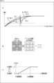
- FIG. 2 is a diagram explaining the pixel value replacement method.
- FIG. 2A shows the relationship between the brightness of the light received by the pixel and the SN ratio in the pixel value replacement method.
- the pixel value of the large pixel RAW signal of the target pixel is compared with the threshold for each of the red, green, and blue pixels in the Bayer array shown in FIG. be done. Then, based on the comparison result, the pixel value of the large pixel RAW signal and the pixel value of the small pixel RAW signal are switched.
- the pixel value Gr/Gb-1 of the large green pixel RAW signal and the pixel value Gr/Gb-2 of the small green pixel RAW signal are switched.
- the brightness at which the pixel value R-1 of the large pixel RAW signal and the pixel value R-2 of the small pixel RAW signal of red are changed, and the pixel value B-1 of the large pixel RAW signal of blue and the pixel value B-1 of the blue pixel RAW signal.
- the brightness at which the pixel value B-2 of the small pixel RAW signal is changed is greatly different. Therefore, in the brightness range sandwiched by the alternate long and short dash lines in A of FIG.
- the large pixel RAW signal with a good SN ratio is used until just before the large pixel RAW signal is saturated (immediately before the upper threshold value shown in C in FIG. 2). (hereinafter referred to as a connecting SN ratio) is an advantage over the luminance changing method and the maximum value changing method.
- the pixel value replacement method is characterized by a good SN ratio at the transition, the possibility of guaranteeing saturation, and the tendency for coloring to occur at the transition.
- Fig. 3 is a diagram for explaining the luminance changing method.
- FIG. 3A shows the relationship between the brightness of light received by a pixel and the SN ratio in the luminance changing method.
- Luminance is calculated and the luminance value is compared with a threshold. Then, based on the comparison result, the pixel value of the large pixel RAW signal and the pixel value of the small pixel RAW signal are switched.
- the sensitivity difference for each pixel color is smoothed by the filter coefficient, resulting in the difference between the pixel value Gr/Gb-1 of the large green pixel RAW signal and the small green pixel RAW signal.
- the pixel value B-1 of the large blue pixel RAW signal and the brightness at which the pixel value B-2 of the small blue pixel RAW signal are changed approximately match each other. Therefore, the range of brightness sandwiched between dashed lines in FIG. 3A is narrowed, and false colors are less likely to occur, which is an advantage over the pixel value replacement method (see A in FIG. 2).
- the color balance differs depending on the color temperature and the color of the subject, so it becomes impossible to guarantee the minimum value of the SN ratio indicated by the dashed line in A of FIG.
- the saturation of the large pixel RAW signal is reduced by the filtering process. Therefore, it is necessary to set the upper limit threshold shown in FIG.
- the SN ratio deteriorates due to brightness in the vicinity.
- the luminance switching method has the characteristics that the SN ratio of the transition is slightly poor, saturation cannot be guaranteed, and coloring is difficult to occur in the transition.
- FIG. 4 is a diagram explaining the maximum value replacement method.
- FIG. 4A shows the relationship between the brightness of the light received by the pixel and the SN ratio in the maximum value switching method.
- the maximum value of the pixel values of the 3 ⁇ 3 tap large pixel RAW signal around the pixel of interest as shown in FIG. A threshold is compared. Then, based on the comparison result, the pixel value of the large pixel RAW signal and the pixel value of the small pixel RAW signal are switched.
- the pixel value Gr/Gb-1 of the large green pixel RAW signal and the pixel value Gr/Gb-2 of the small green pixel RAW signal are switched.
- the brightness at which the pixel value R-1 of the large pixel RAW signal and the pixel value R-2 of the small pixel RAW signal of red are changed, and the pixel value B-1 of the large pixel RAW signal of blue and the pixel value B-1 of the blue pixel RAW signal.
- the brightness at which the pixel value B-2 of the small pixel RAW signal and the pixel value B-2 are changed substantially match each other. Therefore, the range of brightness sandwiched between dashed lines in FIG. 4A is narrowed, and false colors are less likely to occur, which is an advantage over the pixel value replacement method (see A in FIG. 2).
- the maximum value switching method has the characteristic that the SN ratio of the connection is poor, the saturation can be guaranteed, and the coloration of the connection is likely to occur.
- the pixel value changing method, the luminance changing method, and the maximum value changing method each have their own characteristics. and ensuring that pixel values are not saturated.
- the blend ratio calculation unit 21 has a function of determining whether or not the large pixel that is the pixel of interest is saturated. For example, when the blend ratio calculation unit 21 determines that the large pixel serving as the pixel of interest is not saturated, any one of the pixel value replacement method, the luminance replacement method, and the maximum value replacement method is used.
- the calculated blend ratio ⁇ can be used as it is.
- the blend rate calculation unit 21 can use 1 as the blend rate ⁇ when determining that the large pixel serving as the pixel of interest is saturated. As a result, it is possible to both suppress coloring due to the occurrence of false colors and ensure that pixel values are not saturated, thereby improving the image quality of images based on HDR-RAW signals. .
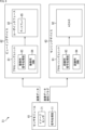
- FIG. 5 is a block diagram showing a configuration example of the blend ratio calculator 21. As shown in FIG.
- the blend ratio calculator 21 includes a first tap generator 31, a luminance generator 32, a maximum value selector 33, a saturation determiner 34, a first selector 35, a calculator 36, a second selector 37, a second tap generator 38, a low-pass filter processor 39, and a third selector 40.
- the first tap generation unit 31 generates 3 ⁇ 3 tap large pixels centered on the pixel of interest, which is the target pixel for calculating the blend ratio ⁇ , from the large pixel RAW signal sequentially supplied to the blend ratio calculation unit 21 .
- a pixel value of the RAW signal is generated and supplied to the luminance generation section 32 and the maximum value selection section 33 .
- the luminance generator 32 calculates the luminance value Y of the target pixel by multiplying the pixel value of the large pixel RAW signal of 3 ⁇ 3 taps by the filter coefficient (see B in FIG. 3 described above). It is supplied to the selector 35.
- the maximum value selection unit 33 selects the maximum value MAX among the pixel values of the 3 ⁇ 3 tap large pixel RAW signal and supplies it to the first selector 35 .
- the saturation determination unit 34 compares the pixel value of the large pixel RAW signal of the pixel of interest with the saturation determination threshold SATU_TH, and outputs a 1-bit saturation determination value SATU based on the comparison result. For example, when the pixel value of the large pixel RAW signal of the target pixel exceeds the saturation determination threshold SATU_TH, the saturation determination unit 34 outputs 1 indicating that the large pixel is saturated as the saturation determination value SATU. On the other hand, when the pixel value of the large pixel RAW signal of the target pixel does not exceed the saturation determination threshold SATU_TH, the saturation determination unit 34 outputs 0 indicating that the large pixel is not saturated as the saturation determination value SATU.
- the saturation determination value SATU output from the saturation determination unit 34 is supplied to the second selector 37 and also output to the outside of the blend ratio calculation unit 21 (a subsequent processing block (not shown)).
- the first selector 35 selects one of the pixel value of the large pixel RAW signal of the pixel of interest, the luminance value Y generated by the luminance generator 32, and the maximum value MAX selected by the maximum value selector 33. , one of them is selected as the reference signal BASE and supplied to the calculator 36 .
- the calculator 36 calculates the blend ratio ⁇ according to the reference signal BASE supplied from the first selector 35 and supplies it to the second selector 37 . That is, the calculator 36 calculates 0 as the blend rate ⁇ when the reference signal BASE is equal to or less than the lower limit threshold. Further, when the reference signal BASE is between the lower limit threshold and the upper limit threshold, the calculation unit 36 calculates a value that increases from 0 to 1.0 as the reference signal BASE increases as the blend ratio ⁇ . . Further, the calculation unit 36 calculates 1.0 as the blend rate ⁇ when the reference signal BASE is equal to or higher than the upper limit threshold.
- the second selector 37 selects the blend ratio ⁇ based on the saturation determination value SATU supplied from the saturation determination section 34 and supplies it to the second tap generation section 38 . For example, when the saturation determination value SATU is not 1, that is, when the saturation determination value SATU is 0, the second selector 37 outputs the blend ratio ⁇ supplied from the calculator 36 as it is. On the other hand, when the saturation determination value SATU is 1, the second selector 37 outputs 1 as the blend ratio ⁇ . That is, when the saturation determination value SATU is 1, it is determined that the large pixels are saturated, so the blend ratio ⁇ is forcibly replaced with 1.
- the second tap generation unit 38 generates a 3 ⁇ 3 tap blend ratio ⁇ centered on the pixel of interest from the blend ratio ⁇ sequentially supplied from the second selector 37, and the low-pass filter processing unit 39 and the third is supplied to the selector 40 of
- the low-pass filter processing unit 39 applies a low-pass filter (simple averaging) to the 3 ⁇ 3 tap blend ratio ⁇ supplied from the second tap generation unit 38, and obtains the blend ratio of the pixel of interest subjected to the low-pass filter. is supplied to the third selector 40 .
- a low-pass filter simple averaging
- the third selector 40 outputs the blend ratio ⁇ as it is when the blend ratio ⁇ of the target pixel to which the low-pass filter is not applied is 1 according to the blend ratio ⁇ of the target pixel to which the low-pass filter is not applied. .
- the third selector 40 outputs the low-pass filtered blend rate ⁇ when the blend rate ⁇ of the target pixel not subjected to the low-pass filter is not 1. That is, when the blend ratio ⁇ becomes 1 or less by applying a low-pass filter to the portion where the blend ratio ⁇ is 1, it is assumed that saturation cannot be guaranteed. 1. Prevent low-pass filtering from being applied to a certain portion.
- a in FIG. 6 represents the original subject.
- White areas are bright areas where small pixel RAW signals are used, and black areas are dark areas where large pixel RAW signals are used.
- the boundary between the white area and the black area has a large contrast difference, and the blending process is performed at this boundary.
- B in FIG. 6 represents an image that has undergone blend processing using the blend rate ⁇ obtained by the conventional technology.
- the boundary between the white area and the black area tends to be jerky and color artifacts may occur, or the saturation of pixels that should not be output may be output. As a result, reliability may be lost.
- the pixel value changing method, the luminance changing method, and the maximum value changing method can both suppress coloring due to the occurrence of false colors and ensure that pixel values are not saturated. I didn't.
- C in FIG. 6 represents an image that has undergone blend processing using the blend rate ⁇ obtained by this technology.
- the present technique compared to the conventional technique, rattling and color artifacts at the boundary between the white area and the black area are suppressed, and the appearance of the subject is closer to that of the original subject. Moreover, since it is guaranteed that the saturation of the large pixel RAW signal is not output, the reliability of the data is high.
- the present technology is based on a luminance changing method in which the luminance value Y generated from the pixel values of a plurality of pixels (for example, 3 ⁇ 3 taps) centering on the target pixel is used as the reference signal BASE, and saturation determination is performed. By performing the saturation determination of the pixel value of the large-pixel RAW signal by the unit 34, it is possible to suppress coloring due to the occurrence of false color and to ensure that the pixel value is not saturated.
- FIG. 7 is a flowchart for explaining blend ratio calculation processing performed in the blend ratio calculation unit 21. As shown in FIG.
- step S ⁇ b>11 the calculator 36 calculates the blend ratio ⁇ according to the reference signal BASE supplied from the first selector 35 and supplies it to the second selector 37 .
- the reference signal BASE any one of the pixel value of the large pixel RAW signal of the target pixel, the luminance value Y generated by the luminance generation unit 32, and the maximum value MAX selected by the maximum value selection unit 33 is selected.
- the luminance value Y it is possible to suppress coloring due to the occurrence of false colors.
- step S12 the saturation determination unit 34 compares the pixel value of the large pixel RAW signal of the pixel of interest with the saturation determination threshold SATU_TH, and obtains the saturation determination value SATU from the comparison result.
- the saturation determination unit 34 then supplies the saturation determination value SATU to the second selector 37 and outputs the saturation determination value SATU to the outside of the blend ratio calculation unit 21 .
- step S13 the second selector 37 determines whether or not the saturation determination value SATU supplied from the saturation determination unit 34 in step S12 is 1.
- step S13 if it is determined in step S13 that the saturation determination value SATU is 1, the process proceeds to step S15, the second selector 37 outputs 1 as the blend ratio ⁇ , and the second tap generator 38 supply to
- step S16 the second tap generator 38 generates a blend rate ⁇ of 3 ⁇ 3 taps centered on the pixel of interest, and the low-pass filter processor 39 and the 3 selector 40.
- step S17 the low-pass filter processing unit 39 applies a low-pass filter to the 3 ⁇ 3 tap blend ratio ⁇ supplied from the second tap generation unit 38, and the low-pass filtered target pixel blend ratio ⁇ is supplied to the third selector 40 .
- step S18 the third selector 40 determines whether or not the blend ratio ⁇ of the target pixel to which the low-pass filter is not applied, supplied from the second tap generation unit 38 in step S16, is 1.
- step S18 If it is determined in step S18 that the blend ratio ⁇ of the pixel of interest to which the low-pass filter has not been applied is 1, the process proceeds to step S19, and the third selector 40 selects the pixel of interest to which the low-pass filter has not been applied. output the blend ratio ⁇ as it is.
- step S18 if it is determined in step S18 that the blend ratio ⁇ of the target pixel to which the low-pass filter has not been applied is not 1, the process proceeds to step S20, and the third selector 40 causes the low-pass filter processing unit 39 outputs the blend ratio ⁇ of the pixel of interest to which the low-pass filter supplied from is applied.
- step S19 or S20 After the processing of step S19 or S20, the processing ends.
- the blending rate calculation unit 21 can calculate the blending rate ⁇ , which has the characteristics that the connecting SN ratio is slightly good, the saturation can be guaranteed, and the connecting coloring is less likely to occur.
- FIG. 8 is a block diagram showing a configuration example of an image processing system including the signal processing section 11. As shown in FIG.
- the image processing system 51 is configured with a sensor module 61, a viewing device 62, and a sensing device 63.
- the sensor module 61 is configured with an image sensor 71 and a signal processing section 11 .
- the image sensor 71 has a sub-pixel structure including large pixels with high sensitivity and small pixels with low sensitivity. It is supplied to the processing section 11 .
- the signal processing unit 11 outputs the image data of the HDR-RAW signal obtained by the blend processing performed by the ⁇ blend processing unit 22 according to the blend ratio ⁇ calculated by the blend ratio calculation unit 21 .
- the signal processing unit 11 also outputs the saturation determination value SATU obtained by the saturation determining unit 34 as a saturation flag.
- the viewing device 62 is configured with a processing unit 81 and a user interface 82 .
- the processing unit 81 has an imaging signal processor 83 and an imaging DNN (Deep Neural Network) 84
- the user interface 82 has a display 85 .
- the image data output from the signal processing unit 11 is supplied to the viewing device 62, the image data is subjected to signal processing for imaging in the signal processing unit 83 for imaging, and the image data is imaged in the DNN 84 for imaging.
- Deep learning for An image based on the image data subjected to signal processing for imaging is displayed on the display 85, and the recognition result of the image data recognized by deep learning for imaging is also displayed on the display 85.
- the sensing device 63 is configured with a processing unit 91 and ADAS (Advanced Driver-Assistance Systems) 92 .
- the processing unit 91 has a recognition signal processor 93 and a recognition DNN 94 .
- the image data and the saturation flag output from the signal processing unit 11 are supplied to the sensing device 63, and the recognition signal processing unit 93 performs signal processing for recognition on the image data with reference to the saturation flag.
- the DNN 94 for recognition performs deep learning for recognition on the image data with reference to the saturation flag. Then, the image data subjected to signal processing for recognition and the recognition result recognized by deep learning for recognition of the image data are supplied to the ADAS 92, and the ADAS 92 controls the vehicle.
- the sensing device 63 performs signal processing for recognition of image data with reference to the saturation flag and deep learning for recognition of image data with reference to the saturation flag, thereby preventing misrecognition. can be avoided.
- the signal processing unit 11 determines whether or not the large pixel RAW signal is saturated, and supplies the saturation flag to the sensing device 63 together with the image data. can do.
- the saturation flag information indicates the timing at which the pixel value of the large pixel RAW signal and the pixel value of the small pixel RAW signal are switched. Therefore, in the sensing device 63, according to the saturation flag, signal processing for recognition suitable for large pixel RAW signals and deep learning algorithm for recognition, signal processing for recognition suitable for small pixel RAW signals and deep layer learning for recognition are performed. You can switch between learning algorithms.
- signal processing for recognition suitable for large-pixel RAW signals and deep learning algorithms for recognition perform processing specialized for dark areas (e.g., noise removal by strongly applying noise reduction before recognition). be able to.
- signal processing for recognition suitable for small-pixel RAW signals and deep learning algorithms for recognition can perform processing specialized for bright portions (for example, removal of flare around the sun).
- the image processing system 51 can perform signal processing for recognition and deep learning for recognition that are optimal for each brightness, thereby improving the recognition rate and avoiding misrecognition. be able to.
- coefficients other than averaging may be used as the coefficients used when the low-pass filter processing unit 39 applies a low-pass filter to the blend ratio ⁇ of 3 ⁇ 3 taps.
- the low-pass filter processing unit 39 may hold a plurality of coefficients and select a coefficient as necessary.
- the sensor module 61 including the signal processing unit 11 as described above can be used in various applications such as an imaging system such as a digital still camera or a digital video camera, a mobile phone with an imaging function, or other equipment with an imaging function. It can be applied to electronic equipment.
- FIG. 9 is a block diagram showing a configuration example of an imaging device mounted on an electronic device.
- the imaging device 101 is configured with an optical system 102, an imaging element 103, a signal processing circuit 104, a monitor 105, and a memory 106, and is capable of capturing still images and moving images.
- the optical system 102 is configured with one or more lenses, guides image light (incident light) from a subject to the imaging element 103, and forms an image on the light receiving surface (sensor section) of the imaging element 103.
- the imaging element 103 As the imaging element 103, the sensor module 61 described above is applied. Electrons are accumulated in the imaging element 103 for a certain period of time according to the image formed on the light receiving surface via the optical system 102 . A signal corresponding to the electrons accumulated in the image sensor 103 is supplied to the signal processing circuit 104 .
- the signal processing circuit 104 performs various signal processing on the pixel signals output from the image sensor 103 .
- An image (image data) obtained by the signal processing performed by the signal processing circuit 104 is supplied to the monitor 105 for display or supplied to the memory 106 for storage (recording).
- the sensor module 61 including the signal processing unit 11 described above By applying the sensor module 61 including the signal processing unit 11 described above to the imaging device 101 configured in this way, for example, it is possible to capture a higher quality image.
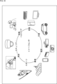
- FIG. 10 is a diagram showing a usage example using the image sensor (imaging element) described above.
- the image sensor described above can be used in various cases for sensing light such as visible light, infrared light, ultraviolet light, and X-rays, for example, as follows.
- ⁇ Devices that capture images for viewing purposes, such as digital cameras and mobile devices with camera functions.
- Devices used for transportation such as in-vehicle sensors that capture images behind, around, and inside the vehicle, surveillance cameras that monitor running vehicles and roads, and ranging sensors that measure the distance between vehicles.
- Devices used in home appliances such as TVs, refrigerators, air conditioners, etc., to take pictures and operate devices according to gestures ⁇ Endoscopes, devices that perform angiography by receiving infrared light, etc.
- Equipment used for medical and healthcare purposes such as surveillance cameras for crime prevention and cameras for personal authentication
- microscopes used for beauty such as microscopes used for beauty
- Sports such as action cameras and wearable cameras for use in sports ⁇ Cameras, etc. for monitoring the condition of fields and crops , agricultural equipment
- a calculation unit that calculates the blend ratio used in a saturation determination unit that compares a pixel value of the large pixel RAW signal of the target pixel with a saturation determination threshold value and outputs a saturation determination value indicating whether or not the large pixel RAW signal of the target pixel is saturated;
- a signal processing device comprising: a first selection unit that selects whether to output the blend rate as it is or replace the blend rate with 1 and output the blend rate according to the saturation determination value.
- a tap generation unit that generates the blend rate of taps in a predetermined range centering on the pixel of interest from the blend rate output from the first selection unit;
- the signal processing device according to (1) or (2) above, further comprising: a low-pass filtering unit that applies a low-pass filter to the blend ratio of the tap.
- a low-pass filtering unit that applies a low-pass filter to the blend ratio of the tap.
- a signal processor as described.
- (6) A blending process of comparing a reference signal based on the large pixel RAW signal of the target pixel with a threshold, and blending the pixel value of the small pixel RAW signal of the target pixel with the pixel value of the large pixel RAW signal of the target pixel.
- Blend ratio calculation unit 22 ⁇ blend processing unit 31
- First tap generation unit 32 Luminance generation unit 33
- Maximum value selection unit 34 Saturation judgment unit 35
- First selector 36 Calculation unit , 37 second selector, 38 second tap generator, 39 low-pass filter processor, 40 third selector, 51 image processing system, 61 sensor module, 62 viewing device, 63 sensing device, 71 image sensor, 81 Processing unit, 82 User interface, 83 Imaging signal processing unit, 84 Imaging DNN, 85 Display, 91 Processing unit, 92 ADAS, 93 Recognition signal processing unit, 94 Recognition DNN
Landscapes
- Engineering & Computer Science (AREA)
- Multimedia (AREA)
- Signal Processing (AREA)
- Physics & Mathematics (AREA)
- General Physics & Mathematics (AREA)
- Theoretical Computer Science (AREA)
- Spectroscopy & Molecular Physics (AREA)
- Image Processing (AREA)
Abstract
Description
図1は、本技術を適用した画像処理部の一実施の形態の構成例を示すブロック図である。
図5は、ブレンド率算出部21の構成例を示すブロック図である。
図7は、ブレンド率算出部21において行われるブレンド率算出処理について説明するフローチャートである。
図8は、信号処理部11を備えた画像処理システムの構成例を示すブロック図である。
上述したような信号処理部11を備えるセンサモジュール61は、例えば、デジタルスチルカメラやデジタルビデオカメラなどの撮像システム、撮像機能を備えた携帯電話機、または、撮像機能を備えた他の機器といった各種の電子機器に適用することができる。
図10は、上述のイメージセンサ(撮像素子)を使用する使用例を示す図である。
・自動停止等の安全運転や、運転者の状態の認識等のために、自動車の前方や後方、周囲、車内等を撮影する車載用センサ、走行車両や道路を監視する監視カメラ、車両間等の測距を行う測距センサ等の、交通の用に供される装置
・ユーザのジェスチャを撮影して、そのジェスチャに従った機器操作を行うために、TVや、冷蔵庫、エアーコンディショナ等の家電に供される装置
・内視鏡や、赤外光の受光による血管撮影を行う装置等の、医療やヘルスケアの用に供される装置
・防犯用途の監視カメラや、人物認証用途のカメラ等の、セキュリティの用に供される装置
・肌を撮影する肌測定器や、頭皮を撮影するマイクロスコープ等の、美容の用に供される装置
・スポーツ用途等向けのアクションカメラやウェアラブルカメラ等の、スポーツの用に供される装置
・畑や作物の状態を監視するためのカメラ等の、農業の用に供される装置
なお、本技術は以下のような構成も取ることができる。
(1)
注目画素の大画素RAW信号に基づいた基準信号と閾値との比較を行い、前記注目画素の大画素RAW信号の画素値に対して前記注目画素の小画素RAW信号の画素値をブレンドするブレンド処理で用いられるブレンド率を算出する算出部と、
前記注目画素の大画素RAW信号の画素値と飽和判定閾値との比較を行い、前記注目画素の大画素RAW信号が飽和しているか否かを示す飽和判定値を出力する飽和判定部と、
前記飽和判定値に従って、前記ブレンド率をそのまま出力するか、前記ブレンド率を1に置き換えて出力するかを選択する第1の選択部と
を備える信号処理装置。
(2)
前記基準信号として、前記注目画素を中心とした複数の画素の画素値から算出される輝度値が用いられる
上記(1)に記載の信号処理装置。
(3)
前記第1の選択部から出力される前記ブレンド率から、前記注目画素を中心とした所定範囲のタップの前記ブレンド率を生成するタップ生成部と、
前記タップの前記ブレンド率に対してローパスフィルタを施すローパスフィルタ処理部と
をさらに備える上記(1)または(2)に記載の信号処理装置。
(4)
前記ローパスフィルタが施される前の前記注目画素の前記ブレンド率が1である場合には、そのブレンド率をそのまま出力し、前記ローパスフィルタが施される前の前記注目画素の前記ブレンド率が1でない場合には、前記ローパスフィルタが施された前記注目画素の前記ブレンド率を出力する第2の選択部
をさらに備える上記(3)に記載の信号処理装置。
(5)
前記ブレンド処理が施されたダイナミックレンジの広い画像を用いた認識処理を行うセンシングデバイスで参照される飽和フラグとして、前記飽和判定値が出力される
上記(1)から(4)までのいずれかに記載の信号処理装置。
(6)
注目画素の大画素RAW信号に基づいた基準信号と閾値との比較を行い、前記注目画素の大画素RAW信号の画素値に対して前記注目画素の小画素RAW信号の画素値をブレンドするブレンド処理で用いられるブレンド率を算出することと、
前記注目画素の大画素RAW信号の画素値と飽和判定閾値との比較を行い、前記注目画素の大画素RAW信号が飽和しているか否かを示す飽和判定値を出力することと、
前記飽和判定値に従って、前記ブレンド率をそのまま出力するか、前記ブレンド率を1に置き換えて出力するかを選択することと
を含む信号処理方法。
(7)
信号処理装置のコンピュータに、
注目画素の大画素RAW信号に基づいた基準信号と閾値との比較を行い、前記注目画素の大画素RAW信号の画素値に対して前記注目画素の小画素RAW信号の画素値をブレンドするブレンド処理で用いられるブレンド率を算出することと、
前記注目画素の大画素RAW信号の画素値と飽和判定閾値との比較を行い、前記注目画素の大画素RAW信号が飽和しているか否かを示す飽和判定値を出力することと、
前記飽和判定値に従って、前記ブレンド率をそのまま出力するか、前記ブレンド率を1に置き換えて出力するかを選択することと
を含む信号処理を実行させるためのプログラム。
Claims (7)
- 注目画素の大画素RAW信号に基づいた基準信号と閾値との比較を行い、前記注目画素の大画素RAW信号の画素値に対して前記注目画素の小画素RAW信号の画素値をブレンドするブレンド処理で用いられるブレンド率を算出する算出部と、
前記注目画素の大画素RAW信号の画素値と飽和判定閾値との比較を行い、前記注目画素の大画素RAW信号が飽和しているか否かを示す飽和判定値を出力する飽和判定部と、
前記飽和判定値に従って、前記ブレンド率をそのまま出力するか、前記ブレンド率を1に置き換えて出力するかを選択する第1の選択部と
を備える信号処理装置。 - 前記基準信号として、前記注目画素を中心とした複数の画素の画素値から生成される輝度値が用いられる
請求項1に記載の信号処理装置。 - 前記第1の選択部から出力される前記ブレンド率から、前記注目画素を中心とした所定範囲のタップの前記ブレンド率を生成するタップ生成部と、
前記タップの前記ブレンド率に対してローパスフィルタを施すローパスフィルタ処理部と
をさらに備える請求項1に記載の信号処理装置。 - 前記ローパスフィルタが施される前の前記注目画素の前記ブレンド率が1である場合には、そのブレンド率をそのまま出力し、前記ローパスフィルタが施される前の前記注目画素の前記ブレンド率が1でない場合には、前記ローパスフィルタが施された前記注目画素の前記ブレンド率を出力する第2の選択部
をさらに備える請求項3に記載の信号処理装置。 - 前記ブレンド処理が施されたダイナミックレンジの広い画像を用いた認識処理を行うセンシングデバイスで参照される飽和フラグとして、前記飽和判定値が出力される
請求項1に記載の信号処理装置。 - 注目画素の大画素RAW信号に基づいた基準信号と閾値との比較を行い、前記注目画素の大画素RAW信号の画素値に対して前記注目画素の小画素RAW信号の画素値をブレンドするブレンド処理で用いられるブレンド率を算出することと、
前記注目画素の大画素RAW信号の画素値と飽和判定閾値との比較を行い、前記注目画素の大画素RAW信号が飽和しているか否かを示す飽和判定値を出力することと、
前記飽和判定値に従って、前記ブレンド率をそのまま出力するか、前記ブレンド率を1に置き換えて出力するかを選択することと
を含む信号処理方法。 - 信号処理装置のコンピュータに、
注目画素の大画素RAW信号に基づいた基準信号と閾値との比較を行い、前記注目画素の大画素RAW信号の画素値に対して前記注目画素の小画素RAW信号の画素値をブレンドするブレンド処理で用いられるブレンド率を算出することと、
前記注目画素の大画素RAW信号の画素値と飽和判定閾値との比較を行い、前記注目画素の大画素RAW信号が飽和しているか否かを示す飽和判定値を出力することと、
前記飽和判定値に従って、前記ブレンド率をそのまま出力するか、前記ブレンド率を1に置き換えて出力するかを選択することと
を含む信号処理を実行させるためのプログラム。
Priority Applications (1)
| Application Number | Priority Date | Filing Date | Title |
|---|---|---|---|
| US18/726,153 US20250071439A1 (en) | 2022-01-12 | 2022-12-27 | Signal processing device, signal processing method, and program |
Applications Claiming Priority (2)
| Application Number | Priority Date | Filing Date | Title |
|---|---|---|---|
| JP2022002749 | 2022-01-12 | ||
| JP2022-002749 | 2022-01-12 |
Publications (1)
| Publication Number | Publication Date |
|---|---|
| WO2023136134A1 true WO2023136134A1 (ja) | 2023-07-20 |
Family
ID=87279037
Family Applications (1)
| Application Number | Title | Priority Date | Filing Date |
|---|---|---|---|
| PCT/JP2022/048173 Ceased WO2023136134A1 (ja) | 2022-01-12 | 2022-12-27 | 信号処理装置および信号処理方法、並びにプログラム |
Country Status (2)
| Country | Link |
|---|---|
| US (1) | US20250071439A1 (ja) |
| WO (1) | WO2023136134A1 (ja) |
Citations (3)
| Publication number | Priority date | Publication date | Assignee | Title |
|---|---|---|---|---|
| JP2007325145A (ja) * | 2006-06-05 | 2007-12-13 | Fujifilm Corp | 画像処理装置および方法並びにプログラム |
| JP2017224971A (ja) * | 2016-06-15 | 2017-12-21 | ソニー株式会社 | 画像処理装置、画像処理方法、およびプログラム |
| JP2018166242A (ja) * | 2017-03-28 | 2018-10-25 | ソニーセミコンダクタソリューションズ株式会社 | 画像処理装置、画像処理方法、および電子機器 |
Family Cites Families (8)
| Publication number | Priority date | Publication date | Assignee | Title |
|---|---|---|---|---|
| EP1865730A3 (en) * | 2006-06-06 | 2010-01-20 | Sony Corporation | Video-signal processing method, program of video-signal processing method, recording medium having recorded thereon program of video-signal processing method, and video-signal processing apparatus |
| JP4645736B2 (ja) * | 2008-12-22 | 2011-03-09 | ソニー株式会社 | 画像処理装置、および画像処理方法、並びにプログラム |
| JP2013066145A (ja) * | 2011-08-31 | 2013-04-11 | Sony Corp | 画像処理装置、および画像処理方法、並びにプログラム |
| JP2013066142A (ja) * | 2011-08-31 | 2013-04-11 | Sony Corp | 画像処理装置、および画像処理方法、並びにプログラム |
| JP5901935B2 (ja) * | 2011-10-24 | 2016-04-13 | 株式会社東芝 | 固体撮像装置及びカメラモジュール |
| JP2013207433A (ja) * | 2012-03-28 | 2013-10-07 | Sony Corp | 固体撮像装置、撮像信号出力方法および電子機器 |
| JP2013219705A (ja) * | 2012-04-12 | 2013-10-24 | Sony Corp | 画像処理装置、および画像処理方法、並びにプログラム |
| KR102408344B1 (ko) * | 2017-10-31 | 2022-06-14 | 삼성전자주식회사 | 영상 처리 장치, 영상 처리 방법 및 컴퓨터 판독가능 기록 매체 |
-
2022
- 2022-12-27 WO PCT/JP2022/048173 patent/WO2023136134A1/ja not_active Ceased
- 2022-12-27 US US18/726,153 patent/US20250071439A1/en active Pending
Patent Citations (3)
| Publication number | Priority date | Publication date | Assignee | Title |
|---|---|---|---|---|
| JP2007325145A (ja) * | 2006-06-05 | 2007-12-13 | Fujifilm Corp | 画像処理装置および方法並びにプログラム |
| JP2017224971A (ja) * | 2016-06-15 | 2017-12-21 | ソニー株式会社 | 画像処理装置、画像処理方法、およびプログラム |
| JP2018166242A (ja) * | 2017-03-28 | 2018-10-25 | ソニーセミコンダクタソリューションズ株式会社 | 画像処理装置、画像処理方法、および電子機器 |
Also Published As
| Publication number | Publication date |
|---|---|
| US20250071439A1 (en) | 2025-02-27 |
Similar Documents
| Publication | Publication Date | Title |
|---|---|---|
| US11671715B2 (en) | High dynamic range technique selection for image processing | |
| US8436910B2 (en) | Image processing apparatus and image processing method | |
| US10200664B2 (en) | Image processing apparatus, image device, image processing method, and program for reducing noise or false colors in an image | |
| JP7077395B2 (ja) | 多重化高ダイナミックレンジ画像 | |
| US8363131B2 (en) | Apparatus and method for local contrast enhanced tone mapping | |
| KR100843084B1 (ko) | 노이즈 저감 방법 및 장치 | |
| US20110080494A1 (en) | Imaging apparatus detecting foreign object adhering to lens | |
| US8681242B2 (en) | Image signal processing system | |
| WO2011151867A1 (ja) | 撮像装置、撮像方法およびプログラム | |
| US8988562B2 (en) | Image processing apparatus and image processing method | |
| JP2010136224A (ja) | 撮像装置及び撮像方法 | |
| CN101690160A (zh) | 用于使用自动聚焦统计的运动检测的方法、系统及设备 | |
| US8189066B2 (en) | Image processing apparatus, image processing method, and computer-readable medium | |
| JP2022179514A (ja) | 制御装置、撮像装置、制御方法およびプログラム | |
| JP7346077B2 (ja) | 画像処理装置、画像処理方法及びプログラム | |
| US20180176445A1 (en) | Imaging device and imaging method | |
| JPWO2019155757A1 (ja) | 画像処理装置、画像処理方法及び画像処理システム | |
| US20050162535A1 (en) | Image processing apparatus and method | |
| WO2023136134A1 (ja) | 信号処理装置および信号処理方法、並びにプログラム | |
| US20100303355A1 (en) | Image processing apparatus, image processing method, and image processing program | |
| JP2010098553A (ja) | 階調補正装置、階調補正方法、プログラム、撮像装置および画像処理装置 | |
| US20080012964A1 (en) | Image processing apparatus, image restoration method and program | |
| US8125527B2 (en) | Motion detection apparatus | |
| KR101327035B1 (ko) | 카메라 모듈 및 이의 이미지 처리 방법 | |
| WO2025047335A1 (ja) | 撮像装置および撮像方法、並びに電子機器 |
Legal Events
| Date | Code | Title | Description |
|---|---|---|---|
| 121 | Ep: the epo has been informed by wipo that ep was designated in this application |
Ref document number: 22920650 Country of ref document: EP Kind code of ref document: A1 |
|
| WWE | Wipo information: entry into national phase |
Ref document number: 18726153 Country of ref document: US |
|
| NENP | Non-entry into the national phase |
Ref country code: DE |
|
| 122 | Ep: pct application non-entry in european phase |
Ref document number: 22920650 Country of ref document: EP Kind code of ref document: A1 |
|
| NENP | Non-entry into the national phase |
Ref country code: JP |
|
| WWP | Wipo information: published in national office |
Ref document number: 18726153 Country of ref document: US |