WO2023135801A1 - Terminal, wireless communication method, and base station - Google Patents
Terminal, wireless communication method, and base station Download PDFInfo
- Publication number
- WO2023135801A1 WO2023135801A1 PCT/JP2022/001378 JP2022001378W WO2023135801A1 WO 2023135801 A1 WO2023135801 A1 WO 2023135801A1 JP 2022001378 W JP2022001378 W JP 2022001378W WO 2023135801 A1 WO2023135801 A1 WO 2023135801A1
- Authority
- WO
- WIPO (PCT)
- Prior art keywords
- csi
- frequency domain
- row
- information
- resource
- Prior art date
Links
Images


Classifications
-
- H—ELECTRICITY
- H04—ELECTRIC COMMUNICATION TECHNIQUE
- H04W—WIRELESS COMMUNICATION NETWORKS
- H04W24/00—Supervisory, monitoring or testing arrangements
- H04W24/10—Scheduling measurement reports ; Arrangements for measurement reports
-
- H—ELECTRICITY
- H04—ELECTRIC COMMUNICATION TECHNIQUE
- H04W—WIRELESS COMMUNICATION NETWORKS
- H04W72/00—Local resource management
- H04W72/04—Wireless resource allocation
Definitions
- the present disclosure relates to terminals, wireless communication methods, and base stations in next-generation mobile communication systems.
- LTE Long Term Evolution
- 3GPP Rel. 10-14 LTE-Advanced (3GPP Rel. 10-14) has been specified for the purpose of further increasing the capacity and sophistication of LTE (Third Generation Partnership Project (3GPP) Release (Rel.) 8, 9).
- LTE successor systems for example, 5th generation mobile communication system (5G), 5G+ (plus), 6th generation mobile communication system (6G), New Radio (NR), 3GPP Rel. 15 and later
- 5G 5th generation mobile communication system
- 5G+ 5th generation mobile communication system
- 6G 6th generation mobile communication system
- NR New Radio
- AI artificial intelligence
- ML machine learning
- RS reference signals
- one of the objects of the present disclosure is to provide a terminal, a wireless communication method, and a base station that can realize suitable use of RS resources.
- a terminal includes a receiver that receives information about the frequency domain density of a channel state information reference signal, and when the frequency domain density is less than 1, different ports and different CDM and a control unit for controlling reception of the channel state information reference signals for which at least one mapping of groups is supported.
- suitable use of RS resources can be realized.
- FIG. 1 is a diagram showing an example of a CSI-RS resource mapping pattern.
- FIG. 2 is a diagram illustrating an example of higher layer parameters related to CSI-RS resource mapping information.
- FIG. 3 is a diagram showing an example of CSI-RS positions in slots and RBs.
- 4A and 4B are diagrams illustrating an example of CSI-RS resource mapping for a specific CSI-RS location configuration (eg, row).
- FIG. 5 is a diagram illustrating another example of CSI-RS resource mapping for a specific CSI-RS location configuration (eg, row).
- 6A to 6C are diagrams showing examples of CSI-RS resource mapping according to aspect 2-1 of the second embodiment.
- FIG. 1 is a diagram showing an example of a CSI-RS resource mapping pattern.
- FIG. 2 is a diagram illustrating an example of higher layer parameters related to CSI-RS resource mapping information.
- FIG. 3 is a diagram showing an example of CSI-RS positions in slots and RBs.
- FIG. 7 is a diagram showing an example of a method for indicating RB positions of CSI-RS resources according to aspect 2-1 of the second embodiment.
- 8A to 8C are diagrams showing examples of CSI-RS resource mapping according to aspect 2-2 of the second embodiment.
- 9A and 9B are diagrams showing other examples of CSI-RS resource mapping according to aspect 2-2 of the second embodiment.
- 10A and 10B are diagrams showing other examples of CSI-RS resource mapping according to aspect 2-2 of the second embodiment.
- 11A and 11B are diagrams showing other examples of CSI-RS resource mapping according to aspect 2-2 of the second embodiment.
- FIG. 12 is a diagram showing a specific CSI-RS position configuration (eg, row) according to aspect 2-2 of the second embodiment.
- FIG. 13 is a diagram showing another example of CSI-RS resource mapping according to aspect 2-2 of the second embodiment.
- 14A and 14B are diagrams showing an example of CSI-RS resource mapping according to a combination of aspects 2-1 and 2-2 of the second embodiment.
- 15A and 15B are diagrams showing other examples of CSI-RS resource mapping according to the combination of aspects 2-1 and 2-2 of the second embodiment.
- 16A and 16B are diagrams showing an example of CSI-RS resource mapping according to aspect 2-3 of the second embodiment.
- FIG. 17 is a diagram showing an example of upper layer parameters related to CSI-RS resource mapping information according to aspect 2-3 of the second embodiment.
- 18A to 18D are diagrams showing other examples of CSI-RS resource mapping according to aspect 2-3 of the second embodiment.
- FIG. 19A and 19B are diagrams showing other examples of CSI-RS resource mapping according to aspect 2-3 of the second embodiment.
- 20A and 20B are diagrams showing an example of CSI-RS resource mapping according to a combination of aspects 2-2 and 2-3 of the second embodiment.
- 21A and 21B are diagrams showing an example of CSI-RS resource mapping according to a combination of aspects 2-1, 2-2, and 2-3 of the second embodiment.
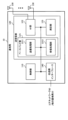
- FIG. 22 is a diagram illustrating an example of a schematic configuration of a wireless communication system according to an embodiment;
- FIG. 23 is a diagram illustrating an example of the configuration of a base station according to one embodiment.
- FIG. 24 is a diagram illustrating an example of the configuration of a user terminal according to an embodiment;
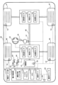
- FIG. 25 is a diagram illustrating an example of hardware configurations of a base station and a user terminal according to an embodiment.
- FIG. 26 is a diagram illustrating an example of a vehicle according to one embodiment;
- CSI-RS For at least one of channel state information (CSI) acquisition, beam management (BM), beam failure recovery (BFR), time and frequency fine tracking in 15/16 NR CSI-RS, for example, is used as the DL RS of.
- multiple-port CSI-RS uses at least one of frequency division multiplexing (FDM), time division multiplexing (TDM), code division multiplexing (CDM (frequency domain OCC, time domain OCC)). are multiplexed.
- FDM frequency division multiplexing
- TDM time division multiplexing
- CDM code division multiplexing
- CSI-RS supports up to 32 ports.
- Multi-port CSI-RS is used, for example, for orthogonalization of multi-input multi-output (MIMO) layers.
- MIMO multi-input multi-output
- different DMRS ports are configured for each layer.
- a different DMRS port is set for each layer in one UE and for each UE.
- CSI-RS supports up to 32 ports with at least one of time domain OCC and frequency domain OCC (up to 4 in time direction and up to 2 in frequency direction), FDM, TDM.
- CSI-RS supports periodic, semi-persistent and aperiodic transmission.
- the CSI-RS frequency density is configurable to adjust the overhead and CSI estimation accuracy.
- Periodic/semi-persistent CSI-RS is set with a predetermined periodicity (for example, Periodicity).
- the predetermined periodicity is set in slot units, specifically any of 4/5/8/10/16/20/32/40/64/80/160/320/640 slots. is set.
- aperiodic CSI-RS all aperiodic CSI-RS resources within the same resource set are transmitted in the same slot.
- CSI-RS resource mapping pattern Rel.
- CSI-RS supports 1, 2, 4, 8, 12, 16, 24, 32 ports (antenna ports, CSI-RS ports). Also, CSI-RS supports 3, 1, and 0.5 as frequency domain density (eg, frequency domain density).
- Non-CDM for example, no CDM
- CDM types include fd-CDM2, cdm4-FD2-TD2, and cdm8-FD2-TD4 (see FIG. 1).
- fd-CDM2 multiplexes 2-port CSI-RS in the same time and frequency by multiplying a frequency domain (FD)-orthogonal cover code (OCC) of length 2 in RE units (FD2 ).
- FD frequency domain
- OCC orthogonal cover code
- CSI-RS supports 1 or 2 starting symbols in one slot for OFDM symbol allocation (eg, OFDM symbol allocation), and supports allocation from each starting symbol to 1/2/4 adjacent symbols.
- CSI-RS frequency domain allocation may be indicated by a bitmap (eg, bitmap indication).
- the frequency domain location of CSI-RS (eg, frequency-domain location) is based on a bitmap provided by a higher layer parameter (eg, frequencyDomainAllocation) for CSI-RS resources and a predetermined value (eg, ki).
- frequencyDomainAllocation may be included in higher layer parameters related to CSI-RS resource mapping (eg, CSI-RS-ResourceMapping IE (see FIG. 2) or CSI-RS-ResourceConfigMobility IE).
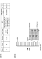
- the predetermined value (eg, ki) for the frequency position of the CSI-RS (eg, CDM group) within the slot may be a value defined in the table for CSI-RS position (see FIG. 3).
- FIG. 3 is a diagram showing an example of CSI-RS locations within a slot.
- Each row of the table has row number, port number, frequency domain density, CDM type, time and frequency (time/frequency) location (component resource (CDM group) location (k bar, l bar)), CDM group index.
- CDM group component resource
- k bar k bar, l bar
- CDM group index k bar, l bar
- each resource position ((RE, symbol), (k′, l′)
- the time/frequency position is the position of time and frequency resources (component resources) of the CSI-RS corresponding to one port.
- the k-bar is a notation with an overline on the "k”.
- the k bar indicates the starting resource element (RE) index of the component resource
- the l bar indicates the starting symbol (OFDM symbol) index of the component resource.
- Row 1 [b3...b0]
- k i-1 f(i)
- Row #2 [b11...b0]
- k i-1 f(i)
- Row #4 [b2...b0]
- k i-1 4f(i)
- Other rows [b5...b0]
- k i-1 2f(i) f(i) indicates the number of the i-th bit of the bitmap (eg, frequencyDomainAllocation) set to 1, and the ceiling function of 1/ ⁇ among the resource blocks configured for CSI-RS reception by the UE (eg, ceil(1/ ⁇ )).
- FIG. 4A shows an example of CSI-RS positions corresponding to row #1.
- the number of ports is 1, the density is 3, and there is no CDM.
- FIG. 4B shows an example of CSI-RS positions corresponding to row #4.
- the number of ports is 4, the density is 1, and the case is fd-CDM2.
- component resources of 2 subcarriers x 1 symbol are double-multiplexed (FDM) in the frequency domain and single-multiplexed in the time domain, resulting in 2 x 1 Component resources are mapped.
- two CSI-RSs are multiplexed (CDM) by multiplying the CSI-RS in each component resource by the FD-OCC of length 2 subcarriers.
- CSI-RS includes two CDM groups, for example, a first CDM group (CDM group #0) includes two ports (eg, port 3000, port 3001), and a second CDM group (CDM group #0) includes #1) includes two ports (eg, port 3002 and port 3003).
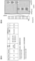
- FIG. 5 shows an example of CSI-RS positions corresponding to row #17.
- the number of ports is 32, the density is 1 (or 0.5), and the case is cdm4-FD2-TD2.
- component resources of 2 subcarriers x 2 symbols are 4-multiplexed (FDM) in the frequency domain and 2-multiplexed (TDM) in the time domain, resulting in 4 x Two component resources are mapped.
- CSI-RS in each component resource is multiplied by FD-OCC of length 2 subcarriers and TD-OCC of length 2 symbols, so that 4 CSI-RS are multiplexed (CDM) be done.
- CSI-RS includes 8 CDM groups, and each CDM group includes 4 ports.
- AI artificial intelligence
- channel estimation also referred to as channel measurement
- decoding of received signals and the like.
- channel state information reference signal For channel estimation, for example, channel state information reference signal (CSI-RS), synchronization signal (SS), synchronization signal/broadcast channel (Synchronization Signal/Physical Broadcast Channel (SS/PBCH)) block, reference for demodulation It may be performed using at least one of a signal (DeModulation Reference Signal (DMRS)), a measurement reference signal (Sounding Reference Signal (SRS)), and the like.
- CSI-RS channel state information reference signal
- SS synchronization signal
- SS/PBCH Synchrom Broadcast Channel
- DMRS DeModulation Reference Signal
- SRS Sounding Reference Signal
- AI artificial intelligence
- ML machine learning
- AI/ML complementation is being used to reduce resources for reference signals (RS) while maintaining channel estimation accuracy.
- RS reference signals
- RS reception measurement capable of high channel estimation accuracy
- the following requirements may be required: - Transmitting and receiving RS in a wide band (contributes to the improvement of reception quality), - Repeated transmission of RSs to combine received channels/signals (combined reception) on the receiving side (contributes to improved reception quality); • High time/frequency density of RS resources (contributes to obtaining good time/frequency correlation).
- the setting of the mapping of the reference signal (eg, CSI-RS) is specified to be controlled based on predetermined periodicity and predetermined resource mapping. ing.
- the overhead of reference signals (eg, CSI-RS/CSI-RS resources) can be reduced by configuring more flexible and dynamic reference signal mapping. is desirable.
- the present inventors studied a suitable RS resource allocation/utilization method and conceived the present embodiment.
- each embodiment of the present disclosure may be applied when AI/ML/prediction is not used. In this case, it is possible to reduce the delay/overhead and change the configuration of the RS without RRC reconfiguration.
- the UE/BS trains the ML model in training mode and implements the ML model in test mode (also called test mode, testing mode, etc.).
- test mode also called test mode, testing mode, etc.
- validation of the accuracy of the ML model trained in the training mode may be performed.
- the UE/BS inputs channel state information, reference signal measurements, etc. to the ML model to obtain highly accurate channel state information/measurements/beam selection/position, future channel state information / Radio link quality etc. may be output.
- AI may be read as an object (also called object, object, data, function, program, etc.) having (implementing) at least one of the following characteristics: Estimates based on observed or collected information; - Choices based on information observed or collected; • Predictions based on observed or collected information.
- the object may be, for example, a terminal, a device such as a base station, or a device. Also, the object may correspond to a program included in the device.
- an ML model may be read as an object that has (enforces) at least one of the following characteristics: Generating an estimate by feeding, Informed to predict estimates; ⁇ Discover characteristics by giving information, • Selecting actions by giving information.
- the ML model may be read as at least one of AI model, predictive analytics, predictive analysis model, and the like. Also, the ML model may be derived using at least one of regression analysis (e.g., linear regression analysis, multiple regression analysis, logistic regression analysis), support vector machines, random forests, neural networks, deep learning, and the like. In this disclosure, model may be translated as at least one of encoder, decoder, tool, and the like.
- regression analysis e.g., linear regression analysis, multiple regression analysis, logistic regression analysis
- model may be translated as at least one of encoder, decoder, tool, and the like.
- the ML model outputs at least one information such as estimated value, predicted value, selected action, classification, etc., based on the input information.
- the UE and the BS are the relevant subjects in order to explain the ML model for communication between the UE and the BS, but the application of each embodiment of the present disclosure is not limited to this.
- the UE and BS in the following embodiments may be read as the first UE and the second UE.
- any UE, BS, etc. in this disclosure may be read as any UE/BS.
- A/B and “at least one of A and B” may be read interchangeably, and “A/B/C” and “at least one of A, B and C” may be interchanged.
- activate, deactivate, indicate (or indicate), select, configure, update, determine, etc. may be read interchangeably.
- supporting, controlling, controllable, operating, and capable of operating may be read interchangeably.
- Radio Resource Control RRC
- RRC parameters RRC parameters
- RRC messages higher layer parameters
- information elements IEs
- settings may be read interchangeably.
- MAC Control Element (CE) Medium Access Control Control Element
- update command update command
- activation/deactivation command may be read interchangeably.
- indexes, IDs, indicators, and resource IDs may be read interchangeably.
- sequences, lists, sets, groups, groups, clusters, subsets, etc. may be read interchangeably.
- a beam report may be read interchangeably as a beam measurement report, a CSI report, a CSI measurement report, a predicted beam report, a predicted CSI report, and the like.
- CSI-RS refers to Non Zero Power (NZP) CSI-RS, Zero Power (ZP) CSI-RS and CSI Interference Measurement (CSI-IM)). At least one may be read interchangeably.
- NZP Non Zero Power
- ZP Zero Power
- CSI-IM CSI Interference Measurement
- measured/reported RS may mean RS measured/reported for beam reporting.
- timing, time, time, slot, subslot, symbol, subframe, etc. may be read interchangeably.
- directions, axes, dimensions, polarizations, polarization components, etc. may be read interchangeably.
- estimation, prediction, and inference may be read interchangeably. Also, in the present disclosure, estimate, predict, and infer may be read interchangeably.
- the RS may be, for example, CSI-RS, SS/PBCH block (SS block (SSB)), and the like.
- the RS index may be a CSI-RS resource indicator (CRI), an SS/PBCH block resource indicator (SS/PBCH block indicator (SSBRI)), or the like.
- CSI feedback CSI feedback information
- CSI report CSI report
- CSI transmission CSI information, CSI, etc.
- a subband may be interchanged with a physical resource block (PRB), a subcarrier, an arbitrary frequency resource unit, or the like.
- PRB physical resource block
- a subcarrier an arbitrary frequency resource unit, or the like.
- the channel state information reference signal (CSI-RS) is taken as an example, but it is not limited to this, and may be applied to any reference signal.
- assigning reference signals, mapping, transmitting, and receiving may be read interchangeably.
- Setting/applying a value larger than the maximum periodicity in existing systems (eg, before Rel. 16) as the CSI-RS resource period/periodicity may be supported. For example, setting/applying a predetermined periodicity value greater than 640 slots as the CSI-RS resource periodicity/periodicity may be supported.
- the predetermined periodicity value may be, for example, 1280 slots, 2560 slots, and so on.
- a new CSI-RS resource offset value (for example, time offset value) may be set for a predetermined periodicity value. For example, a setting of 0 to (X-1) slots may be supported as an offset corresponding to periodic X slots.
- the predetermined periodicity value may be set in a granularity/unit other than the slot. For example, using a unit having a granularity larger than a slot (eg, subframe/frame/ms/s/minis/hours), the periodicity of CSI-RS resources (eg, a predetermined periodicity value) can be set. may be supported. In this case, the periodicity offset value may be set with the granularity of the slot, or may be set with a new granularity (for example, a unit having a granularity larger than that of the slot).
- an offset corresponding to subframes/frames/ms/s/minis/hours of periodicity X may be set from 0 to (X-1) slots.
- offsets corresponding to subframes/frames/ms/s/minis/hours of periodicity X may be set from 0 to (X ⁇ 1) subframes/frames/ms/s/minis/hours.
- the granularity/unit of periodicity and the granularity/unit of offset may be commonly set/applied.
- ⁇ Second embodiment> frequency domain configuration of CSI-RS resources will be described. Note that the configuration shown in the second embodiment may be applied in combination with the content shown in the first embodiment as appropriate.
- the newly set/applied frequency domain density value may be applied to each row of the CSI-RS resource positions shown in FIG. 3, or may be selectively applied to some rows. .
- the newly set/applied frequency domain density value is applied to a new row different from the row (eg, row #1 to row #18) indicating the CSI-RS resource position shown in FIG. good.
- row may be read as a configuration of CSI-RS locations (eg, CSI-RS locations within a slot) or CSI-RS location candidates.
- a new frequency domain density (eg, ⁇ _new) different from the frequency domain density of the existing system (eg, 3, 1, 0.5)
- at least one of the following options 2-1-1 to 2-1-2 may be applied.
- a new frequency domain density (eg, ⁇ _new) may be defined as 1/N.
- N may be a predetermined integer value.
- N may be a multiple of 2/4/8/12 . . .
- the new frequency domain density value 1/N may be less than 0.5.
- FIG. 6A shows an example of CSI-RS resource mapping patterns (or parameters) corresponding to row #2
- FIG. 6B shows an example of CSI-RS positions corresponding to row #2.
- the N for frequency domain density may be notified to the UE through higher layer signaling.
- a new frequency domain density (eg, ⁇ _new) may be defined in M/N.
- M may be a predetermined integer value and N may be a predetermined integer value or a multiple of 2/4/8/12 .
- M and N may be set separately, and may be defined by M ⁇ N (or M>N).
- the new frequency domain density value M/N may be less than or greater than 0.5.
- 1/ ⁇ may be an integer value or may not be an integer value.
- the M/N for frequency domain density may be notified to the UE by higher layer signaling. Note that the values of M and N may be notified to the UE, respectively. In this case, by controlling the values of M and N, it is possible to flexibly set the frequency domain density.
- the M RBs may be contiguous RBs or non-contiguous RBs.
- FIG. 6C shows an example of CSI-RS positions corresponding to row #2.
- RBs resource blocks
- a case is shown in which two RBs that are repeated every five RBs are non-consecutive, but the present invention is not limited to this.
- the RB positions occupied by CSI-RS are defined in the specification. may be specified, or may be directed to the UE from the network.
- the RB position occupied by CSI-RS may be read as RB position where CSI-RS is allocated/RB position mapped/RB position allocated.
- a starting RB position within the N RBs may be defined/indicated.
- the starting RB position offset for the lowest (or highest) RB index among the N RBs may be defined/indicated.
- the indicated starting RB position may mean the RB position occupied by CSI-RS.
- M RBs occupied by CSI-RS may be frequency-allocated by providing a fixed offset (eg, Y RB offsets) between RBs occupied by CSI-RS.
- Y may be set by higher layer signaling or defined in the specification.
- the default start position may be, for example, the lowest (or highest) RB index among N RBs.
- the starting RB position among N RBs may be included in a table used for CSI-RS resource mapping positions, or may be included in higher layer parameters for CSI-RS resource mapping.
- a bitmap indicating RB positions (eg, RB positions) for the new frequency domain density values may be set (Fig. 7).
- Option 2-1-1 only one bit may be set to 1 among a plurality of bits indicating RBs occupied by CSI-RS.
- Option 2-1-2 may be set such that the sum of the number of bits set to 1 among the plurality of bits is equal to M.
- '0001' may mean that the CSI-RS pattern is mapped to the first (or last) RB every four RBs.
- '00010101' may mean that the CSI-RS pattern is mapped to the ⁇ i, i+2, i+4 ⁇ th RB or the ⁇ i+3, i+5, i+7 ⁇ th RB every 8 RBs.
- the default starting position may be, for example, a configuration in which M consecutive RBs with the lowest (or highest) RB index among N RBs are occupied by CSI-RS.
- the bitmap may be included in a table used for CSI-RS resource mapping positions, or may be included in higher layer parameters related to CSI-RS resource mapping.
- the configuration of CSI-RS locations within a slot may be applied across multiple RBs (or different RBs).
- the configuration of CSI-RS positions within a slot may be, for example, at least one of row #1 to row #18 (or a newly defined/set row) included in the table shown in FIG.
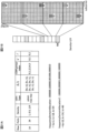
- FIG. 8A shows an example of CSI-RS resource mapping patterns (or parameters) corresponding to row #14, and FIG. 8B shows an example of CSI-RS positions in the existing system corresponding to row #14.
- the number of ports is 24, the density is 0.5, and the case is cdm4-FD2-TD2. That is, the CSI-RS resource mapping pattern (or row 14) is repeated only once every two RBs.
- FIG. 8B shows a case where the CSI-RS is mapped to one of two RBs and the CSI-RS is not mapped to the other.
- component resources of 2 subcarriers x 2 symbols are triple-multiplexed (FDM) in the frequency domain and double-multiplexed (TDM) in the time domain. maps 3 ⁇ 2 component resources.
- CSI-RS in each component resource is multiplied by FD-OCC of length 2 subcarriers and TD-OCC of length 2 symbols, so that 4 CSI-RS are multiplexed (CDM) be done.
- CSI-RS includes 6 CDM groups, and each CDM group includes 4 ports.
- FIG. 8C shows an example of CSI-RS positions corresponding to row #14 when the second aspect is applied.
- the number of ports is 24, the density is 0.5, and the case is cdm4-FD2-TD2. That is, the CSI-RS resource mapping pattern is repeated only once every two resource blocks (eg, RBs). Also, here the CSI-RS is mapped on both (or across) the two RBs. For example, different ports/CDM groups are mapped to two RBs.
- component resources of 2 subcarriers x 2 symbols are triple-multiplexed (FDM) in the frequency domain and double-multiplexed (TDM) in the time domain. maps 3 ⁇ 2 component resources.
- CSI-RS in each component resource is multiplied by FD-OCC of length 2 subcarriers and TD-OCC of length 2 symbols, so that 4 CSI-RS are multiplexed (CDM) be done.
- CSI-RS includes 6 CDM groups, and each CDM group includes 4 ports.
- CDM groups 0, 1, 3 and 4 are mapped to the first RB and CDM groups 2 and 5 are mapped to the second RB.
- CSI-RS mapping flexibility is achieved. Together, it is possible to obtain frequency domain diversity. Also, it is possible to reduce the density of the frequency domain in one slot. Furthermore, by applying it in combination with aspect 2-1, it becomes possible to effectively reduce the density of the frequency domain.
- the value of kbar/ki in the CSI-RS location configuration (eg, CSI-RS resource mapping table)
- the range may be extended/changed.
- the bitmap length (or size) set/notified by higher layer parameters (eg, FrequencyDomainAllocation) related to frequency domain allocation may be extended.
- the higher layer parameter (eg frequencyDomainAllocation) may indicate frequency domain resource occupation (eg frequency domain resource occupation) in multiple RBs.
- the bitmap length set/notified by the upper layer parameter may be changeable (or variable) based on predetermined conditions (eg, frequency domain density of CSI-RS). For example, if the frequency domain density is 0.5, the bitmap length (or size) may be extended by a factor of two. Also, the range of values of kbar/ki may be expanded (eg, [0,22] (for FD2), [0,23] (for fd-CDM2)).
- bitmap length extension may be supported only for a specific CSI-RS location configuration (eg, a specific row), may be supported only for all rows, or may be supported only for a new of rows.
- a specific row may be, for example, a row other than row #1, row #2, and row #4.
- a new row may be a row that is introduced for the purpose of mapping different CDM groups/ports to different RBs.
- bitmap lengths of other rows except row #1, row #2, row #4 are extended, the following relationships may be defined for each row of the table for CSI-RS locations.
- k i-1 2f(i) f(i) denotes the number of the i-th bit of the bitmap that is set to 1 and is repeated for every two consecutive RBs (eg, if the frequency domain density is 0.5).
- higher layer parameters eg, ⁇ evenPRBs, oddPRBs ⁇
- RBs indicated for frequency domain density 0.5 may indicate RBs to which a specific CDM group (eg, CDM group 0) is mapped. good.
- FIG. 9A shows an example of a CSI-RS resource mapping pattern corresponding to row #14.
- the network eg, base station
- a case is shown in which "100000001010" is designated as the bitmap corresponding to row #14.
- the UE selects a row corresponding to the CSI-RS (here, row #14) based on higher layer parameters including a bitmap notified from the base station, and then determines the frequency domain location of the CSI-RS. .
- the UE may determine the row based on the port/density/CDM type indicated by the higher layer parameters, or the UE may be notified of information designating the row by the higher layer parameters.
- FIG. 9B shows a case where CSI-RSs (different CDM groups/ports) corresponding to row #14 are mapped in two RBs.
- the reference point of ki in the frequency direction may be one RB (for example, subcarrier 0 of an RB with a small index) among a plurality of (here, two) RBs.
- FIG. 9A shows the case of using the rows included in the CSI-RS position table in the existing system, it is not limited to this.
- New CSI-RS location configurations eg, new rows
- mapping different CDM groups/ports to different RBs see FIG. 10A.
- FIG. 10A shows an example of a CSI-RS resource mapping pattern corresponding to the new row#x.
- the number of ports is 48
- the density is 0.5
- the case is cdm4-FD2-TD2.
- the case where the frequency domain is indicated by k0, k1, k2, k3, k4, and k5 is shown.
- the network may indicate to the UE the size-extended bitmap as a higher layer parameter (eg, frequencyDomainAllocation) for frequency domain allocation of CSI-RS.
- a case is shown in which "101010101010" is specified as the bitmap corresponding to row#x.
- the UE selects a row (here, row #x) corresponding to the CSI-RS based on higher layer parameters including a bitmap notified from the base station, and then determines the frequency domain location of the CSI-RS. .
- the UE may determine the row based on the port/density/CDM type indicated by the higher layer parameters, or the UE may be notified of information designating the row by the higher layer parameters.
- FIG. 10B shows an example of CSI-RS positions corresponding to row#x.
- CSI-RS resources are mapped to both (or across) two RBs.
- different ports/CDM groups are mapped to two RBs.
- CDM groups 0, 1, 2, 6, 7 and 8 are mapped to the first RB and CDM groups 3, 4, 5, 9, 10 and 11 are mapped to the second RB. ing.
- the reference point of ki in the frequency direction may be one RB (for example, subcarrier 0 of an RB with a small index) among a plurality of (here, two) RBs.
- 9A and 10A show the case of extending the bitmap length, but without extending the bitmap length, the k bar (eg, ki ) with an offset added (or the range of k bar expanded).
- a new row may be introduced in the table for CSI-RS locations, and the range of kbar/ki in the new row may be defined differently than the existing rows. For example, 0 ⁇ k bar ⁇ 12/ ⁇ 1 and 0 ⁇ ki ⁇ 11.
- the indicated resource mapping allocation (k-bar, l-bar) may be repeated at RBs of 1/ ⁇ .
- a higher layer parameter for frequency domain allocation eg, frequencyDomainAllocation
- frequencyDomainAllocation may indicate the resource allocation position of the frequency domain in one RB.
- FIG. 11A shows an example of a CSI-RS resource mapping pattern corresponding to the new row#x.
- the number of ports is 24, the density is 0.5, and the case is cdm4-FD2-TD2.
- the case where the frequency domain is indicated by k0, k1+12, and k2 is shown. That is, an offset (here, +12) is added in the frequency direction to the CDM groups (here, CDM groups 1 and 4) corresponding to k1.
- the network may indicate to the UE a bitmap whose size is not expanded as a higher layer parameter (eg, frequencyDomainAllocation) for frequency domain allocation of CSI-RS.
- a case is shown in which "101010" is designated as the bitmap corresponding to row#x.
- the UE selects a row (here, row #x) corresponding to the CSI-RS based on higher layer parameters including a bitmap notified from the base station, and then determines the frequency domain location of the CSI-RS. .
- the UE may determine the row based on the port/density/CDM type indicated by the higher layer parameters, or the UE may be notified of information designating the row by the higher layer parameters.
- FIG. 11B shows an example of CSI-RS positions corresponding to row#x.
- CSI-RS resources are mapped to both (or across) two RBs.
- different ports/CDM groups are mapped to two RBs.
- CDM groups 0, 2, 3 and 5 are mapped to the first RB
- CDM groups 1 and 4 are mapped to the second RB.
- the reference point of ki in the frequency direction may be one RB (for example, subcarrier 0 of the RB with the smallest index) among a plurality of (here, two) RBs.
- the reference point of ki to which a predetermined offset (here, 12) is added may be the other RB (eg, subcarrier 0 of the RB with the higher index).
- FIG. 12 shows an example of CSI-RS resource mapping patterns (or parameters) respectively corresponding to row#x and row#y.
- the number of ports is 48
- the density is 0.5
- the case is cdm4-FD2-TD2.
- cases where the frequency domain is indicated by k0, k1, k2, k0+12, k1+12, and k2+12 are shown.
- row #x and row #y the values of (k bar, l bar) corresponding to each CDM group are defined differently (or the order is changed).
- the network may indicate to the UE a bitmap whose size is not expanded as a higher layer parameter (eg, frequencyDomainAllocation) for frequency domain allocation of CSI-RS.
- a case is shown in which "101010" is designated as the bitmap corresponding to row#x/row#y.
- UE selects a row corresponding to CSI-RS (here, row #x or row #y) based on higher layer parameters including a bitmap notified from the base station, and then the frequency domain of CSI-RS Determine location.
- the UE may determine the row based on the port/density/CDM type indicated by the higher layer parameters, or the UE may be notified of information designating the row by the higher layer parameters.
- FIG. 13 shows an example of CSI-RS positions respectively corresponding to row#x and row#y.
- CSI-RS resources are mapped to both (or across) two RBs. For example, different ports/CDM groups are mapped to two RBs.
- CDM groups 0, 1, 2, 6, 7, 8 are mapped to the first RB and CDM groups 3, 4, 5, 9, 10, 11 are mapped to the second RB.
- CDM groups 0, 1, 2, 3, 4, 5 are mapped to the first RB and CDM groups 6, 7, 8, 9, 10, 11 are mapped to the second RB.
- the frequency domain density is 0.5 as a case where the frequency domain density is less than 1, but the applicable frequency domain density is not limited to 0.5.
- Aspect 2-2 may be applied to frequency domain densities other than 0.5 (for example, aspect 2-1 and aspect 2-2 may be applied in combination).
- FIG. 14A shows an example of a CSI-RS resource mapping pattern corresponding to row #14.
- N 1/4 as frequency domain density is supported
- the network may indicate to the UE the size-extended bitmap as a higher layer parameter (eg, frequencyDomainAllocation) for frequency domain allocation of CSI-RS.
- a higher layer parameter eg, frequencyDomainAllocation
- bitmap length extension may be supported only for a specific CSI-RS location configuration (eg, a specific row), may be supported only for all rows, or may be supported only for a new of rows.
- a specific row may be, for example, a row other than row #1, row #2, and row #4.
- the occupied RB position (eg, occupied RB position(s)) indicated/defined in aspect 2-1 may indicate the RB position of a specific CDM group index (eg, CDM group index 0).
- the occupied RB position may be indicated by higher layer signaling or may be defined in use for each row.
- the UE selects a row (here, row #x) corresponding to the CSI-RS based on higher layer parameters including a bitmap notified from the base station, and then determines the frequency domain location of the CSI-RS. .
- the UE may determine the row based on the port/density/CDM type indicated by the higher layer parameters, or the UE may be notified of information designating the row by the higher layer parameters.
- FIG. 14B shows an example of CSI-RS positions corresponding to row #14.
- CSI-RS resources may be mapped across 4 RBs (here mapped to 3 RBs). For example, different ports/CDM groups are allowed to be mapped to 4 RBs.
- CDM groups 0, 3 are mapped to the first RB
- CDM groups 1, 4 are mapped to the second RB
- CDM groups 2, 5 are mapped to the third RB
- CDM groups 2, 5 are mapped to the fourth RB. indicates the case where no CSI group is mapped.
- FIG. 14A shows the case of extending the bitmap length, but without extending the bitmap length, offset to k bars (eg, ki) defined/set in the CSI-RS location configuration (eg, row). (or the range of k bar is expanded) (see FIG. 15A).
- k bars eg, ki
- a new row may be introduced in the table for CSI-RS locations, and the range of kbar/ki in the new row may be defined differently than the existing rows. For example, 0 ⁇ k bar ⁇ 12/ ⁇ 1 and 0 ⁇ ki ⁇ 11.
- the indicated resource mapping allocation (k-bar, l-bar) may be repeated at RBs of 1/ ⁇ .
- a higher layer parameter for frequency domain allocation eg, frequencyDomainAllocation
- frequencyDomainAllocation may indicate the resource allocation position of the frequency domain in one RB.
- FIG. 15A shows an example of a CSI-RS resource mapping pattern corresponding to the new row#x.
- the number of ports is 24, the density is 1/4, and the case is cdm4-FD2-TD2.
- the cases where the frequency domain is indicated by k0, k1+12, and k2+24 are shown. That is, the CDM group corresponding to k1 (here, CDM groups 1 and 4) and the CDM group corresponding to k2 (here, CDM groups 2 and 5) are offset in the frequency direction.
- the offset may be a multiple of a predetermined value (eg, 12).
- the offset value may be determined based on predetermined parameters. For example, the offset value may be determined based on at least one of CDM type, number of ports, frequency domain density, and RRC configured parameters.
- the network may indicate to the UE a bitmap whose size is not expanded as a higher layer parameter (eg, frequencyDomainAllocation) for frequency domain allocation of CSI-RS. For example, add a table of CSI-RS locations within a slot that includes more than 12 frequency offsets as shown above with a predetermined rule, and decide whether to use the existing table or the added table based on the upper layer parameters. You can decide. Alternatively, new rows may be added to existing columns to determine which rows to reference based on upper layer parameters. Here, a case is shown in which "101010" is designated as the bitmap corresponding to row#x.
- a higher layer parameter eg, frequencyDomainAllocation
- the UE selects a row (here, row #x) corresponding to the CSI-RS based on higher layer parameters including a bitmap notified from the base station, and then determines the frequency domain location of the CSI-RS. .
- the UE may determine the row based on the port/density/CDM type indicated by the higher layer parameters, or the UE may be notified of information designating the row by the higher layer parameters.
- FIG. 15B shows an example of CSI-RS positions corresponding to row#x.
- CSI-RS resources may be mapped across 4 RBs (here mapped to 3 RBs). For example, different ports/CDM groups are allowed to be mapped to 4 RBs.
- CDM groups 0, 3 are mapped to the first RB
- CDM groups 1, 4 are mapped to the second RB
- CDM groups 2, 5 are mapped to the third RB
- CDM groups 2, 5 are mapped to the fourth RB. indicates the case where no CSI group is mapped.
- the reference point of ki in the frequency direction may be one RB (for example, subcarrier 0 of the RB with the smallest index) among a plurality of (here, four) RBs.
- the offset (eg, 12/24) is based on the subcarrier, but it is not limited to this.
- the offset unit may be RB in the present disclosure.
- the offset added to k1 may be 1 (RB) and the offset added to k2 may be 2 (RB).
- mapping of CSI-RS resources in the frequency domain is flexibly controlled, and the overhead of CSI-RS resources mapped to the frequency domain is reduced. can do.
- aspect 2-3 is a configuration of CSI-RS positions in which multiple start symbols are set in one slot (for example, rows #11, #13, #14, #17 of a table relating to CSI-RS positions, or new row).
- the frequency domain resource allocation of the CSI-RS resources may be supported to configure the frequency domain resource allocation of the CSI-RS resources separately (eg, differently) for each starting symbol.
- FIG. 16A shows a case where multiple start symbols are set in one slot, and CSI-RS frequency domain resource allocation is commonly set for multiple start symbols (eg, l0, l1). ing.
- the frequency domain resource allocations of CDM groups 0-2 mapped to the first start symbol and the frequency domain resource allocations of CDM groups 3-5 mapped to the second start symbol are the same. set. Specifically, CDM group 0 mapped to the first start symbol and CDM group 3 mapped to the second start symbol are assigned to common frequency domain resources.
- FIG. 16B shows a case where the frequency domain resource allocation of CSI-RS is set separately (eg, differently) for each start symbol when multiple start symbols are set in one slot.
- the frequency-domain resource allocations for CDM groups 0-2 mapped to the first starting symbol and the frequency-domain resource allocations for CDM groups 3-5 mapped to the second starting symbol are set separately.
- CDM group 0 mapped to the first start symbol and CDM group 3 mapped to the second start symbol are assigned to different frequency domain resources.
- Bitmaps corresponding to multiple (eg, two) frequency domains may be set/indicated/applied to multiple (eg, two) start symbols in one slot. Bitmaps corresponding to multiple frequency domains may be set by higher layer parameters (see FIG. 17).
- FIG. 17 shows an example of higher layer parameters (for example, CSI-RS-ResourceMapping) related to CSI-RS resource mapping.
- the network eg, base station
- the UE may apply multiple (eg, two) signaled frequency-domain bitmaps to different starting symbols.
- FIG. 17 shows a case where the size (or bitmap length) of the second bitmap is 6, but this is not restrictive and other values may be supported.
- the second bitmap (eg frequencyDomainAllocation2) may be an additional bitmap that is added in addition to the first bitmap (eg frequencyDomainAllocation).
- the second bitmap (eg frequencyDomainAllocation2) may only be present if a specific CSI-RS location configuration (eg row) is set/indicated.
- a specific row may be a row (for example, row #13/#14/#16/#17) in which a plurality of start symbols are set within one slot. If the second bitmap is not included when a specific row is set, the UE applies the same rule as the CSI-RS resource mapping pattern of the existing system (Rel.15/16) good.
- FIG. 18A shows an example of a CSI-RS resource mapping pattern corresponding to row #14.
- the numbers of ports are 24, 20 and 28, the densities are 1 and 0.5, and cdm4-FD2-TD2 are shown. It also shows the case where the frequency domains corresponding to the first start symbol (eg, l0) and the second start symbol (eg, l1) are denoted by k0, k1, and k2. Note that the number of ports to be set may be specified by higher layer signaling.
- the network uses a first frequency domain resource allocation (eg, frequencyDomainAllocation/first bitmap) and a second frequency domain resource allocation ( For example, frequencyDomainAllocation2/second bitmap) may be notified to the UE.
- a first frequency domain resource allocation eg, frequencyDomainAllocation/first bitmap
- a second frequency domain resource allocation For example, frequencyDomainAllocation2/second bitmap
- the UE selects a row corresponding to the CSI-RS (here, row #14) based on higher layer parameters including a bitmap notified from the base station, and then determines the frequency domain location of the CSI-RS. .
- the UE may determine the row based on the port/density/CDM type indicated by the higher layer parameters, or the UE may be notified of information designating the row by the higher layer parameters.
- FIG. 18B corresponds to CSI-RS resources with 24 ports
- FIG. 18C corresponds to CSI-RS resources with 20 ports
- FIG. 18D corresponds to CSI-RS resources with 28 ports. ing.
- FIG. 18B shows a case where "101010" is notified as the first bitmap and "010101" is notified as the second bitmap when the number of ports is 24 (six CDM groups). .
- FIG. 18C shows a case where "101010" is notified as the first bitmap and "000101" is notified as the second bitmap when the number of ports is 20 (five CDM groups). .
- FIG. 18D shows a case where "101010" is notified as the first bitmap and "101101" is notified as the second bitmap when the number of ports is 28 (seven CDM groups). .
- FIGS. 18A to 18D show the case of notifying the UE of multiple bitmaps, the present invention is not limited to this.
- the second bitmap eg, frequencyDomainAllocation2
- the k bars eg, ki
- a new row may be introduced in the table for CSI-RS locations, and the definition of k bar/ki in the new row may be defined differently from the existing rows.
- a configuration of ki corresponding to the first starting symbol plus a predetermined offset may be applied to the second starting symbol.
- a modulo operation may be applied to the predetermined offset, for example.
- FIG. 19A shows an example of a CSI-RS resource mapping pattern corresponding to the new row#x.
- the case is shown where the number of ports is 24, the density is 1, 0.5, and cdm4-FD2-TD2.
- the frequency domain corresponding to the first start symbol is defined by k0, k1, k2, and the frequency domain corresponding to the second start symbol is defined by (k0+2) mod2, (k1+2) mod2, (k2+2) mod2. It shows the case where
- the network may indicate the bitmap to the UE as a higher layer parameter (eg, frequencyDomainAllocation) for frequency domain allocation of CSI-RS.
- a case is shown in which "101010" is designated as the bitmap corresponding to row#x.
- the UE selects a row (here, row #x) corresponding to the CSI-RS based on higher layer parameters including a bitmap notified from the base station, and then determines the frequency domain location of the CSI-RS. .
- the UE may determine the row based on the port/density/CDM type indicated by the higher layer parameters, or the UE may be notified of information designating the row by the higher layer parameters.
- Aspect 2-3 may be applied in combination with at least one of Aspects 2-1 and 2-2.
- FIG. 20A shows an example of a CSI-RS resource mapping pattern corresponding to row #14.
- the case is shown where the number of ports is 24, the density is 1, 0.5, and cdm4-FD2-TD2. It also shows the case where the frequency domains corresponding to the first start symbol (eg, l0) and the second start symbol (eg, l1) are denoted by k0, k1, and k2. Note that the frequency domain density and the like to be set may be specified by higher layer signaling.
- the network uses a first frequency domain resource allocation (eg, frequencyDomainAllocation/first bitmap) and a second frequency domain resource allocation ( For example, frequencyDomainAllocation2/second bitmap) may be notified to the UE.
- a first frequency domain resource allocation eg, frequencyDomainAllocation/first bitmap
- a second frequency domain resource allocation For example, frequencyDomainAllocation2/second bitmap
- the UE selects a row corresponding to the CSI-RS (here, row #14) based on higher layer parameters including a bitmap notified from the base station, and then determines the frequency domain location of the CSI-RS. .
- the UE may determine the row based on the port/density/CDM type indicated by the higher layer parameters, or the UE may be notified of information designating the row by the higher layer parameters.
- FIG. 20B shows a case where "000000101010” is notified as the first bitmap and "010101000000” is notified as the second bitmap when the number of ports is 24 (six CDM groups). .
- CDM groups 0, 1, 2 corresponding to the first starting symbol are mapped to the first RB
- CDM groups 3, 4, 5 corresponding to the second starting symbol are mapped to the second RB. It shows the case where
- bitmap indications of different frequency domain allocations are supported, and if the frequency domain density is less than 1, multiple ports with different allocations of frequency domain resources can be assigned to different RBs. Mapping is possible.
- FIGS. 20A and 20B show the case of notifying the UE of multiple bitmaps, the present invention is not limited to this.
- the second bitmap eg, frequencyDomainAllocation2
- the k bars eg, ki
- start symbols may be separately defined/configured.
- a new frequency domain density (eg, ⁇ _new 1/N or M / N) different from the existing system is applied as the value of the frequency domain density of the CSI-RS resource, and multiple (eg, two) starts within one slot If the symbols are configured, different port/CDM group mappings for multiple RBs (or different RBs) may be supported, and different frequency domain resource allocations for different starting symbols may be supported.
- ⁇ _new 1/N or M / N
- FIG. 21A shows an example of a CSI-RS resource mapping pattern corresponding to row #14.
- the case is shown where the number of ports is 24, the density is 1, 0.5, 1/4, and cdm4-FD2-TD2. It also shows the case where the frequency domains corresponding to the first start symbol (eg, l0) and the second start symbol (eg, l1) are denoted by k0, k1, and k2. Note that the frequency domain density and the like to be set may be specified by higher layer signaling.
- the network uses a first frequency domain resource allocation (eg, frequencyDomainAllocation/first bitmap) and a second frequency domain resource allocation ( For example, frequencyDomainAllocation2/second bitmap) may be notified to the UE.
- a first frequency domain resource allocation eg, frequencyDomainAllocation/first bitmap
- a second frequency domain resource allocation For example, frequencyDomainAllocation2/second bitmap
- the UE selects a row corresponding to the CSI-RS (here, row #14) based on higher layer parameters including a bitmap notified from the base station, and then determines the frequency domain location of the CSI-RS. .
- the UE may determine the row based on the port/density/CDM type indicated by the higher layer parameters, or the UE may be notified of information designating the row by the higher layer parameters.
- CDM groups 0, 1 and 2 corresponding to the first starting symbol are mapped to different RBs
- CDM groups 3, 4 and 5 corresponding to the second starting symbol are mapped to different RBs.
- the frequency domain resources of CDM groups 0, 1 and 2 corresponding to the first starting symbol and the frequency domain resources of CDM groups 3, 4 and 5 corresponding to the second starting symbol are configured separately. .
- FIGS. 21A and 21B show the case of notifying the UE of multiple bitmaps, the present invention is not limited to this.
- the second bitmap eg, frequencyDomainAllocation2
- the k bars eg, ki
- start symbols may be separately defined/configured.
- Which of aspects 2-1 to 2-3 is applied may be set in the UE by a higher layer parameter, may be reported by the UE as UE capability information, or may be defined by the specification. good too. Alternatively, which of aspects 2-1 to 2-3 is applied may be determined in consideration of UE capability information reported from the UE and higher layer parameters set in the UE. .
- UE capability information In the above first embodiment to second embodiment, the following UE capabilities may be set. Note that the UE capabilities below may be read as parameters (eg, higher layer parameters) set in the UE from the network (eg, base station).
- each embodiment may be applied only when the corresponding UE capabilities are reported.
- UE capability information may be defined as to whether to support a value greater than a predetermined value for the time domain periodicity of CSI-RS.
- UE capability information regarding whether to support a predetermined value (eg, a new value not supported by existing systems) for the frequency domain density of CSI-RS may be defined.
- UE capability information may be defined as to whether the UE supports mapping different ports/CDM groups to different RBs.
- the above first and second embodiments may be configured to be applied to a UE that supports/reports at least one of the UE capabilities described above.
- the above embodiment may be configured to be applied to a UE set by a network.
- wireless communication system A configuration of a wireless communication system according to an embodiment of the present disclosure will be described below.
- communication is performed using any one of the radio communication methods according to the above embodiments of the present disclosure or a combination thereof.
- FIG. 22 is a diagram showing an example of a schematic configuration of a wireless communication system according to one embodiment.
- the wireless communication system 1 may be a system that realizes communication using Long Term Evolution (LTE), 5th generation mobile communication system New Radio (5G NR), etc. specified by the Third Generation Partnership Project (3GPP). .
- LTE Long Term Evolution
- 5G NR 5th generation mobile communication system New Radio
- 3GPP Third Generation Partnership Project
- the wireless communication system 1 may also support dual connectivity between multiple Radio Access Technologies (RATs) (Multi-RAT Dual Connectivity (MR-DC)).
- RATs Radio Access Technologies
- MR-DC is dual connectivity between LTE (Evolved Universal Terrestrial Radio Access (E-UTRA)) and NR (E-UTRA-NR Dual Connectivity (EN-DC)), dual connectivity between NR and LTE (NR-E -UTRA Dual Connectivity (NE-DC)), etc.
- RATs Radio Access Technologies
- MR-DC is dual connectivity between LTE (Evolved Universal Terrestrial Radio Access (E-UTRA)) and NR (E-UTRA-NR Dual Connectivity (EN-DC)), dual connectivity between NR and LTE (NR-E -UTRA Dual Connectivity (NE-DC)), etc.
- LTE Evolved Universal Terrestrial Radio Access
- EN-DC E-UTRA-NR Dual Connectivity
- NE-DC NR-E -UTRA Dual Connectivity
- the LTE (E-UTRA) base station (eNB) is the master node (MN), and the NR base station (gNB) is the secondary node (SN).
- the NR base station (gNB) is the MN, and the LTE (E-UTRA) base station (eNB) is the SN.
- the wireless communication system 1 has dual connectivity between multiple base stations within the same RAT (for example, dual connectivity (NR-NR Dual Connectivity (NN-DC) in which both MN and SN are NR base stations (gNB) )) may be supported.
- dual connectivity NR-NR Dual Connectivity (NN-DC) in which both MN and SN are NR base stations (gNB)
- gNB NR base stations
- a wireless communication system 1 includes a base station 11 forming a macrocell C1 with a relatively wide coverage, and base stations 12 (12a-12c) arranged in the macrocell C1 and forming a small cell C2 narrower than the macrocell C1. You may prepare.
- a user terminal 20 may be located within at least one cell. The arrangement, number, etc. of each cell and user terminals 20 are not limited to the embodiment shown in the figure.
- the base stations 11 and 12 are collectively referred to as the base station 10 when not distinguished.
- the user terminal 20 may connect to at least one of the multiple base stations 10 .
- the user terminal 20 may utilize at least one of carrier aggregation (CA) using a plurality of component carriers (CC) and dual connectivity (DC).
- CA carrier aggregation
- CC component carriers
- DC dual connectivity
- Each CC may be included in at least one of the first frequency band (Frequency Range 1 (FR1)) and the second frequency band (Frequency Range 2 (FR2)).
- Macrocell C1 may be included in FR1, and small cell C2 may be included in FR2.
- FR1 may be a frequency band below 6 GHz (sub-6 GHz)
- FR2 may be a frequency band above 24 GHz (above-24 GHz). Note that the frequency bands and definitions of FR1 and FR2 are not limited to these, and for example, FR1 may correspond to a higher frequency band than FR2.
- the user terminal 20 may communicate using at least one of Time Division Duplex (TDD) and Frequency Division Duplex (FDD) in each CC.
- TDD Time Division Duplex
- FDD Frequency Division Duplex
- a plurality of base stations 10 may be connected by wire (for example, an optical fiber conforming to Common Public Radio Interface (CPRI), X2 interface, etc.) or wirelessly (for example, NR communication).
- wire for example, an optical fiber conforming to Common Public Radio Interface (CPRI), X2 interface, etc.
- NR communication for example, when NR communication is used as a backhaul between the base stations 11 and 12, the base station 11 corresponding to the upper station is an Integrated Access Backhaul (IAB) donor, and the base station 12 corresponding to the relay station (relay) is an IAB Also called a node.
- IAB Integrated Access Backhaul
- relay station relay station
- the base station 10 may be connected to the core network 30 directly or via another base station 10 .
- the core network 30 may include, for example, at least one of Evolved Packet Core (EPC), 5G Core Network (5GCN), Next Generation Core (NGC), and the like.
- EPC Evolved Packet Core
- 5GCN 5G Core Network
- NGC Next Generation Core
- the user terminal 20 may be a terminal compatible with at least one of communication schemes such as LTE, LTE-A, and 5G.
- a radio access scheme based on orthogonal frequency division multiplexing may be used.
- OFDM orthogonal frequency division multiplexing
- CP-OFDM Cyclic Prefix OFDM
- DFT-s-OFDM Discrete Fourier Transform Spread OFDM
- OFDMA Orthogonal Frequency Division Multiple Access
- SC-FDMA Single Carrier Frequency Division Multiple Access
- a radio access method may be called a waveform.
- other radio access schemes for example, other single-carrier transmission schemes and other multi-carrier transmission schemes
- the UL and DL radio access schemes may be used as the UL and DL radio access schemes.
- a downlink shared channel Physical Downlink Shared Channel (PDSCH)
- PDSCH Physical Downlink Shared Channel
- PBCH Physical Broadcast Channel
- PDCCH Physical Downlink Control Channel
- an uplink shared channel (PUSCH) shared by each user terminal 20 an uplink control channel (PUCCH), a random access channel (Physical Random Access Channel (PRACH)) or the like may be used.
- PUSCH uplink shared channel
- PUCCH uplink control channel
- PRACH Physical Random Access Channel
- User data, upper layer control information, System Information Block (SIB), etc. are transmitted by the PDSCH.
- User data, higher layer control information, and the like may be transmitted by PUSCH.
- a Master Information Block (MIB) may be transmitted by the PBCH.
- Lower layer control information may be transmitted by the PDCCH.
- the lower layer control information may include, for example, downlink control information (DCI) including scheduling information for at least one of PDSCH and PUSCH.
- DCI downlink control information
- the DCI that schedules PDSCH may be called DL assignment, DL DCI, etc.
- the DCI that schedules PUSCH may be called UL grant, UL DCI, etc.
- PDSCH may be replaced with DL data
- PUSCH may be replaced with UL data.
- a control resource set (CControl Resource SET (CORESET)) and a search space (search space) may be used for PDCCH detection.
- CORESET corresponds to a resource searching for DCI.
- the search space corresponds to the search area and search method of PDCCH candidates.
- a CORESET may be associated with one or more search spaces. The UE may monitor CORESETs associated with certain search spaces based on the search space settings.
- One search space may correspond to PDCCH candidates corresponding to one or more aggregation levels.
- One or more search spaces may be referred to as a search space set. Note that “search space”, “search space set”, “search space setting”, “search space set setting”, “CORESET”, “CORESET setting”, etc. in the present disclosure may be read interchangeably.
- PUCCH channel state information
- acknowledgment information for example, Hybrid Automatic Repeat reQuest ACKnowledgement (HARQ-ACK), ACK/NACK, etc.
- SR scheduling request
- a random access preamble for connection establishment with a cell may be transmitted by the PRACH.
- downlink, uplink, etc. may be expressed without adding "link”.
- various channels may be expressed without adding "Physical" to the head.
- synchronization signals SS
- downlink reference signals DL-RS
- the DL-RS includes a cell-specific reference signal (CRS), a channel state information reference signal (CSI-RS), a demodulation reference signal (DeModulation Reference Signal (DMRS)), Positioning Reference Signal (PRS)), Phase Tracking Reference Signal (PTRS)), etc.
- CRS cell-specific reference signal
- CSI-RS channel state information reference signal
- DMRS Demodulation reference signal
- PRS Positioning Reference Signal
- PTRS Phase Tracking Reference Signal
- the synchronization signal may be, for example, at least one of a Primary Synchronization Signal (PSS) and a Secondary Synchronization Signal (SSS).
- PSS Primary Synchronization Signal
- SSS Secondary Synchronization Signal
- a signal block including SS (PSS, SSS) and PBCH (and DMRS for PBCH) may be called SS/PBCH block, SS Block (SSB), and so on.
- SS, SSB, etc. may also be referred to as reference signals.
- DMRS may also be called a user terminal-specific reference signal (UE-specific reference signal).
- FIG. 23 is a diagram illustrating an example of the configuration of a base station according to one embodiment.
- the base station 10 comprises a control section 110 , a transmission/reception section 120 , a transmission/reception antenna 130 and a transmission line interface 140 .
- One or more of each of the control unit 110, the transmitting/receiving unit 120, the transmitting/receiving antenna 130, and the transmission path interface 140 may be provided.
- this example mainly shows the functional blocks of the features of the present embodiment, and it may be assumed that the base station 10 also has other functional blocks necessary for wireless communication. A part of the processing of each unit described below may be omitted.
- the control unit 110 controls the base station 10 as a whole.
- the control unit 110 can be configured from a controller, a control circuit, and the like, which are explained based on common recognition in the technical field according to the present disclosure.
- the control unit 110 may control signal generation, scheduling (for example, resource allocation, mapping), and the like.
- the control unit 110 may control transmission/reception, measurement, etc. using the transmission/reception unit 120 , the transmission/reception antenna 130 and the transmission line interface 140 .
- the control unit 110 may generate data to be transmitted as a signal, control information, a sequence, etc., and transfer them to the transmission/reception unit 120 .
- the control unit 110 may perform call processing (setup, release, etc.) of communication channels, state management of the base station 10, management of radio resources, and the like.
- the transmitting/receiving section 120 may include a baseband section 121 , a radio frequency (RF) section 122 and a measuring section 123 .
- the baseband section 121 may include a transmission processing section 1211 and a reception processing section 1212 .
- the transmitting/receiving unit 120 is configured from a transmitter/receiver, an RF circuit, a baseband circuit, a filter, a phase shifter, a measurement circuit, a transmitting/receiving circuit, etc., which are explained based on common recognition in the technical field according to the present disclosure. be able to.
- the transmission/reception unit 120 may be configured as an integrated transmission/reception unit, or may be configured from a transmission unit and a reception unit.
- the transmission section may be composed of the transmission processing section 1211 and the RF section 122 .
- the receiving section may be composed of a reception processing section 1212 , an RF section 122 and a measurement section 123 .
- the transmitting/receiving antenna 130 can be configured from an antenna described based on common recognition in the technical field related to the present disclosure, such as an array antenna.
- the transmitting/receiving unit 120 may transmit the above-described downlink channel, synchronization signal, downlink reference signal, and the like.
- the transmitting/receiving unit 120 may receive the above-described uplink channel, uplink reference signal, and the like.
- the transmitting/receiving unit 120 may form at least one of the transmission beam and the reception beam using digital beamforming (eg, precoding), analog beamforming (eg, phase rotation), or the like.
- digital beamforming eg, precoding
- analog beamforming eg, phase rotation
- the transmission/reception unit 120 (transmission processing unit 1211) performs Packet Data Convergence Protocol (PDCP) layer processing, Radio Link Control (RLC) layer processing (for example, RLC retransmission control), Medium Access Control (MAC) layer processing (for example, HARQ retransmission control), etc. may be performed to generate a bit string to be transmitted.
- PDCP Packet Data Convergence Protocol
- RLC Radio Link Control
- MAC Medium Access Control
- HARQ retransmission control for example, HARQ retransmission control
- the transmission/reception unit 120 (transmission processing unit 1211) performs channel coding (which may include error correction coding), modulation, mapping, filtering, and discrete Fourier transform (DFT) on the bit string to be transmitted. Processing (if necessary), Inverse Fast Fourier Transform (IFFT) processing, precoding, transmission processing such as digital-to-analog conversion may be performed, and the baseband signal may be output.
- channel coding which may include error correction coding
- modulation modulation
- mapping mapping
- filtering filtering
- DFT discrete Fourier transform
- DFT discrete Fourier transform
- the transmitting/receiving unit 120 may perform modulation to a radio frequency band, filter processing, amplification, and the like on the baseband signal, and may transmit the radio frequency band signal via the transmitting/receiving antenna 130. .
- the transmitting/receiving unit 120 may perform amplification, filtering, demodulation to a baseband signal, etc. on the radio frequency band signal received by the transmitting/receiving antenna 130.
- the transmission/reception unit 120 (reception processing unit 1212) performs analog-to-digital conversion, Fast Fourier transform (FFT) processing, and Inverse Discrete Fourier transform (IDFT) processing on the acquired baseband signal. )) processing (if necessary), filtering, demapping, demodulation, decoding (which may include error correction decoding), MAC layer processing, RLC layer processing and PDCP layer processing. User data and the like may be acquired.
- FFT Fast Fourier transform
- IDFT Inverse Discrete Fourier transform
- the transmitting/receiving unit 120 may measure the received signal.
- the measurement unit 123 may perform Radio Resource Management (RRM) measurement, Channel State Information (CSI) measurement, etc. based on the received signal.
- the measurement unit 123 measures received power (for example, Reference Signal Received Power (RSRP)), reception quality (for example, Reference Signal Received Quality (RSRQ), Signal to Interference plus Noise Ratio (SINR), Signal to Noise Ratio (SNR)) , signal strength (for example, Received Signal Strength Indicator (RSSI)), channel information (for example, CSI), and the like may be measured.
- RSRP Reference Signal Received Power
- RSSQ Reference Signal Received Quality
- SINR Signal to Noise Ratio
- RSSI Received Signal Strength Indicator
- channel information for example, CSI
- the transmission path interface 140 transmits and receives signals (backhaul signaling) to and from devices included in the core network 30, other base stations 10, etc., and user data (user plane data) for the user terminal 20, control plane data, and the like. Data and the like may be obtained, transmitted, and the like.
- the transmitting unit and receiving unit of the base station 10 in the present disclosure may be configured by at least one of the transmitting/receiving unit 120, the transmitting/receiving antenna 130, and the transmission line interface 140.
- Transmitting/receiving section 120 provides information on time-domain resources indicated in units of time longer than a slot and information on frequency-domain resources supporting at least a frequency-domain density of less than 0.5 with respect to the channel state information reference signal. You may send at least one.
- the control unit 110 may control mapping of channel state information reference signals corresponding to at least one of information on time domain resources and information on frequency domain resources.
- the transmitting/receiving section 120 may transmit information about the frequency domain density of the channel state information reference signal.
- the control unit 110 may control transmission of channel state information reference signals in which mapping of at least one of different ports and different CDM groups to multiple resource blocks is supported when the frequency domain density is less than one.
- the transmitting/receiving section 120 may transmit information about the start symbol of the channel state information reference signal.
- control section 110 may control transmission of channel state information reference signals in which frequency domain resources are configured separately for each start symbol.
- FIG. 24 is a diagram illustrating an example of the configuration of a user terminal according to an embodiment.
- the user terminal 20 includes a control section 210 , a transmission/reception section 220 and a transmission/reception antenna 230 .
- One or more of each of the control unit 210, the transmitting/receiving unit 220, and the transmitting/receiving antenna 230 may be provided.
- this example mainly shows the functional blocks of the features of the present embodiment, and it may be assumed that the user terminal 20 also has other functional blocks necessary for wireless communication. A part of the processing of each unit described below may be omitted.
- the control unit 210 controls the user terminal 20 as a whole.
- the control unit 210 can be configured from a controller, a control circuit, and the like, which are explained based on common recognition in the technical field according to the present disclosure.
- the control unit 210 may control signal generation, mapping, and the like.
- the control unit 210 may control transmission/reception, measurement, etc. using the transmission/reception unit 220 and the transmission/reception antenna 230 .
- the control unit 210 may generate data, control information, sequences, etc. to be transmitted as signals and transfer them to the transmission/reception unit 220 .
- the transmitting/receiving section 220 may include a baseband section 221 , an RF section 222 and a measurement section 223 .
- the baseband section 221 may include a transmission processing section 2211 and a reception processing section 2212 .
- the transmitting/receiving unit 220 can be configured from a transmitter/receiver, an RF circuit, a baseband circuit, a filter, a phase shifter, a measuring circuit, a transmitting/receiving circuit, etc., which are explained based on common recognition in the technical field according to the present disclosure.
- the transmission/reception unit 220 may be configured as an integrated transmission/reception unit, or may be configured from a transmission unit and a reception unit.
- the transmission section may be composed of a transmission processing section 2211 and an RF section 222 .
- the receiving section may include a reception processing section 2212 , an RF section 222 and a measurement section 223 .
- the transmitting/receiving antenna 230 can be configured from an antenna described based on common recognition in the technical field related to the present disclosure, such as an array antenna.
- the transmitting/receiving unit 220 may receive the above-described downlink channel, synchronization signal, downlink reference signal, and the like.
- the transmitting/receiving unit 220 may transmit the above-described uplink channel, uplink reference signal, and the like.
- the transmitter/receiver 220 may form at least one of the transmission beam and the reception beam using digital beamforming (eg, precoding), analog beamforming (eg, phase rotation), or the like.
- digital beamforming eg, precoding
- analog beamforming eg, phase rotation
- the transmitting/receiving unit 220 (transmission processing unit 2211) performs PDCP layer processing, RLC layer processing (eg, RLC retransmission control), MAC layer processing (eg, , HARQ retransmission control) and the like may be performed to generate a bit string to be transmitted.
- RLC layer processing eg, RLC retransmission control
- MAC layer processing eg, HARQ retransmission control
- the transmission/reception unit 220 (transmission processing unit 2211) performs channel coding (which may include error correction coding), modulation, mapping, filtering, DFT processing (if necessary), and IFFT processing on a bit string to be transmitted. , precoding, digital-analog conversion, and other transmission processing may be performed, and the baseband signal may be output.
- Whether or not to apply DFT processing may be based on transform precoding settings. Transmitting/receiving unit 220 (transmission processing unit 2211), for a certain channel (for example, PUSCH), if transform precoding is enabled, the above to transmit the channel using the DFT-s-OFDM waveform
- the DFT process may be performed as the transmission process, or otherwise the DFT process may not be performed as the transmission process.
- the transmitting/receiving unit 220 may perform modulation to a radio frequency band, filter processing, amplification, and the like on the baseband signal, and may transmit the radio frequency band signal via the transmitting/receiving antenna 230. .
- the transmitting/receiving section 220 may perform amplification, filtering, demodulation to a baseband signal, etc. on the radio frequency band signal received by the transmitting/receiving antenna 230.
- the transmission/reception unit 220 (reception processing unit 2212) performs analog-to-digital conversion, FFT processing, IDFT processing (if necessary), filtering, demapping, demodulation, decoding (error correction) on the acquired baseband signal. decoding), MAC layer processing, RLC layer processing, PDCP layer processing, and other reception processing may be applied to acquire user data and the like.
- the transmitting/receiving section 220 may measure the received signal.
- the measurement unit 223 may perform RRM measurement, CSI measurement, etc. based on the received signal.
- the measuring unit 223 may measure received power (eg, RSRP), received quality (eg, RSRQ, SINR, SNR), signal strength (eg, RSSI), channel information (eg, CSI), and the like.
- the measurement result may be output to control section 210 .
- the transmitter and receiver of the user terminal 20 in the present disclosure may be configured by at least one of the transmitter/receiver 220 and the transmitter/receiver antenna 230 .
- the transmitting/receiving unit 220 provides information on time-domain resources indicated in units of time longer than a slot and information on frequency-domain resources supporting at least a frequency-domain density of less than 0.5 with respect to the channel state information reference signal. At least one may be received.
- the control unit 210 may control reception of the channel state information reference signal based on at least one of information on time domain resources and information on frequency domain resources (aspects of the first embodiment/second embodiment 2-1).
- Information about time-domain resources may include information about offsets indicated in time units longer than slots.
- Information about frequency domain resources may include information about one or more resource blocks to which the channel state information reference signal is allocated in a plurality of resource blocks.
- Information about one or more resource blocks to which channel state information reference signals are assigned may be indicated in bitmap form.
- the transmitting/receiving unit 220 may receive information about the frequency domain density of the channel state information reference signal.
- the control unit 210 may control the reception of channel state information reference signals supporting at least one mapping of different ports and different CDM groups to multiple resource blocks when the frequency domain density is less than 1 ( Aspect 2-2) of the second embodiment.
- the transmitting/receiving unit 220 may receive frequency domain allocation information of channel state reference signals including bitmaps indicating subcarriers in multiple resource blocks.
- the bitmap size may vary depending on the frequency domain density.
- the transmitting/receiving unit 220 receives the frequency domain allocation information of the channel state reference signal, and the control unit 210 controls the reception of the channel state information reference signal by applying a predetermined offset to the frequency domain allocation information of the channel state reference signal.
- the transmitting/receiving unit 220 may receive information about the start symbol of the channel state information reference signal.
- the control unit 210 may control reception of channel state information reference signals in which frequency domain resources are configured separately for each start symbol (aspect of the second embodiment 2-3).
- the transmitting/receiving unit 220 may receive multiple bitmaps indicating the frequency domain allocation of channel state information corresponding to each starting symbol. If a slot includes a first start symbol and a second start symbol, the frequency domain position of the channel state reference signal corresponding to the second start symbol is the channel state reference corresponding to the first start symbol. A predetermined offset may be applied to the frequency domain location of the signal. The number of CDM groups mapped to each starting symbol may be set differently.
- each functional block may be implemented using one device physically or logically coupled, or directly or indirectly using two or more physically or logically separated devices (e.g. , wired, wireless, etc.) and may be implemented using these multiple devices.
- a functional block may be implemented by combining software in the one device or the plurality of devices.
- function includes judgment, decision, determination, calculation, calculation, processing, derivation, investigation, search, confirmation, reception, transmission, output, access, resolution, selection, selection, establishment, comparison, assumption, expectation, deem , broadcasting, notifying, communicating, forwarding, configuring, reconfiguring, allocating, mapping, assigning, etc.
- a functional block (component) that performs transmission may be called a transmitting unit, a transmitter, or the like. In either case, as described above, the implementation method is not particularly limited.
- a base station, a user terminal, etc. in an embodiment of the present disclosure may function as a computer that performs processing of the wireless communication method of the present disclosure.
- FIG. 25 is a diagram illustrating an example of hardware configurations of a base station and a user terminal according to an embodiment.
- the base station 10 and user terminal 20 described above may be physically configured as a computer device including a processor 1001, a memory 1002, a storage 1003, a communication device 1004, an input device 1005, an output device 1006, a bus 1007, and the like. .
- the hardware configuration of the base station 10 and the user terminal 20 may be configured to include one or more of each device shown in the figure, or may be configured without some devices.
- processor 1001 may be implemented by one or more chips.
- predetermined software program
- the processor 1001 performs calculations, communication via the communication device 1004 and at least one of reading and writing data in the memory 1002 and the storage 1003 .
- the processor 1001 operates an operating system and controls the entire computer.
- the processor 1001 may be configured by a central processing unit (CPU) including an interface with peripheral devices, a control device, an arithmetic device, registers, and the like.
- CPU central processing unit
- control unit 110 210
- transmission/reception unit 120 220
- FIG. 10 FIG. 10
- the processor 1001 reads programs (program codes), software modules, data, etc. from at least one of the storage 1003 and the communication device 1004 to the memory 1002, and executes various processes according to them.
- programs program codes
- software modules software modules
- data etc.
- the control unit 110 (210) may be implemented by a control program stored in the memory 1002 and running on the processor 1001, and other functional blocks may be similarly implemented.
- the memory 1002 is a computer-readable recording medium, such as Read Only Memory (ROM), Erasable Programmable ROM (EPROM), Electrically EPROM (EEPROM), Random Access Memory (RAM), or at least any other suitable storage medium. may be configured by one.
- the memory 1002 may also be called a register, cache, main memory (main storage device), or the like.
- the memory 1002 can store executable programs (program code), software modules, etc. for implementing a wireless communication method according to an embodiment of the present disclosure.
- the storage 1003 is a computer-readable recording medium, for example, a flexible disk, a floppy (registered trademark) disk, a magneto-optical disk (for example, a compact disk (Compact Disc ROM (CD-ROM), etc.), a digital versatile disk, Blu-ray disc), removable disc, hard disk drive, smart card, flash memory device (e.g., card, stick, key drive), magnetic stripe, database, server, or other suitable storage medium may be configured by Storage 1003 may also be called an auxiliary storage device.
- a computer-readable recording medium for example, a flexible disk, a floppy (registered trademark) disk, a magneto-optical disk (for example, a compact disk (Compact Disc ROM (CD-ROM), etc.), a digital versatile disk, Blu-ray disc), removable disc, hard disk drive, smart card, flash memory device (e.g., card, stick, key drive), magnetic stripe, database, server, or other suitable storage medium may be configured by Storage 1003 may also
- the communication device 1004 is hardware (transmitting/receiving device) for communicating between computers via at least one of a wired network and a wireless network, and is also called a network device, a network controller, a network card, a communication module, or the like.
- the communication device 1004 includes a high-frequency switch, duplexer, filter, frequency synthesizer, etc. in order to realize at least one of frequency division duplex (FDD) and time division duplex (TDD), for example. may be configured to include
- the transmitting/receiving unit 120 (220), the transmitting/receiving antenna 130 (230), and the like described above may be realized by the communication device 1004.
- the transmitter/receiver 120 (220) may be physically or logically separated into a transmitter 120a (220a) and a receiver 120b (220b).
- the input device 1005 is an input device (for example, keyboard, mouse, microphone, switch, button, sensor, etc.) that receives input from the outside.
- the output device 1006 is an output device (for example, a display, a speaker, a Light Emitting Diode (LED) lamp, etc.) that outputs to the outside. Note that the input device 1005 and the output device 1006 may be integrated (for example, a touch panel).
- Each device such as the processor 1001 and the memory 1002 is connected by a bus 1007 for communicating information.
- the bus 1007 may be configured using a single bus, or may be configured using different buses between devices.
- the base station 10 and the user terminal 20 include a microprocessor, a digital signal processor (DSP), an application specific integrated circuit (ASIC), a programmable logic device (PLD), a field programmable gate array (FPGA), etc. It may be configured including hardware, and a part or all of each functional block may be realized using the hardware. For example, processor 1001 may be implemented using at least one of these pieces of hardware.
- DSP digital signal processor
- ASIC application specific integrated circuit
- PLD programmable logic device
- FPGA field programmable gate array
- a signal may also be a message.
- a reference signal may be abbreviated as RS, and may also be called a pilot, a pilot signal, etc., depending on the applicable standard.
- a component carrier may also be called a cell, a frequency carrier, a carrier frequency, or the like.
- a radio frame may consist of one or more periods (frames) in the time domain.
- Each of the one or more periods (frames) that make up a radio frame may be called a subframe.
- a subframe may consist of one or more slots in the time domain.
- a subframe may be a fixed time length (eg, 1 ms) independent of numerology.
- a numerology may be a communication parameter applied to at least one of transmission and reception of a certain signal or channel.
- Numerology for example, subcarrier spacing (SCS), bandwidth, symbol length, cyclic prefix length, transmission time interval (TTI), number of symbols per TTI, radio frame configuration , a particular filtering process performed by the transceiver in the frequency domain, a particular windowing process performed by the transceiver in the time domain, and/or the like.
- a slot may consist of one or more symbols (Orthogonal Frequency Division Multiplexing (OFDM) symbol, Single Carrier Frequency Division Multiple Access (SC-FDMA) symbol, etc.) in the time domain.
- OFDM Orthogonal Frequency Division Multiplexing
- SC-FDMA Single Carrier Frequency Division Multiple Access
- a slot may also be a unit of time based on numerology.
- a slot may contain multiple mini-slots. Each minislot may consist of one or more symbols in the time domain. A minislot may also be referred to as a subslot. A minislot may consist of fewer symbols than a slot.
- a PDSCH (or PUSCH) transmitted in time units larger than a minislot may be referred to as PDSCH (PUSCH) Mapping Type A.
- PDSCH (or PUSCH) transmitted using minislots may be referred to as PDSCH (PUSCH) mapping type B.
- Radio frames, subframes, slots, minislots and symbols all represent time units when transmitting signals. Radio frames, subframes, slots, minislots and symbols may be referred to by other corresponding designations. Note that time units such as frames, subframes, slots, minislots, and symbols in the present disclosure may be read interchangeably.
- one subframe may be called a TTI
- a plurality of consecutive subframes may be called a TTI
- one slot or one minislot may be called a TTI. That is, at least one of the subframe and TTI may be a subframe (1 ms) in existing LTE, a period shorter than 1 ms (eg, 1-13 symbols), or a period longer than 1 ms may be Note that the unit representing the TTI may be called a slot, mini-slot, or the like instead of a subframe.
- TTI refers to, for example, the minimum scheduling time unit in wireless communication.
- a base station performs scheduling to allocate radio resources (frequency bandwidth, transmission power, etc. that can be used by each user terminal) to each user terminal on a TTI basis.
- radio resources frequency bandwidth, transmission power, etc. that can be used by each user terminal
- a TTI may be a transmission time unit such as a channel-encoded data packet (transport block), code block, or codeword, or may be a processing unit such as scheduling and link adaptation. Note that when a TTI is given, the time interval (for example, the number of symbols) in which transport blocks, code blocks, codewords, etc. are actually mapped may be shorter than the TTI.
- one or more TTIs may be the minimum scheduling time unit. Also, the number of slots (the number of mini-slots) constituting the minimum time unit of the scheduling may be controlled.
- a TTI having a time length of 1 ms may be called a normal TTI (TTI in 3GPP Rel. 8-12), normal TTI, long TTI, normal subframe, normal subframe, long subframe, slot, or the like.
- a TTI that is shorter than a normal TTI may be called a shortened TTI, a short TTI, a partial or fractional TTI, a shortened subframe, a short subframe, a minislot, a subslot, a slot, and the like.
- the long TTI (e.g., normal TTI, subframe, etc.) may be replaced with a TTI having a time length exceeding 1 ms
- the short TTI e.g., shortened TTI, etc.
- a TTI having the above TTI length may be read instead.
- a resource block is a resource allocation unit in the time domain and frequency domain, and may include one or more consecutive subcarriers (subcarriers) in the frequency domain.
- the number of subcarriers included in the RB may be the same regardless of the neumerology, eg twelve.
- the number of subcarriers included in an RB may be determined based on neumerology.
- an RB may contain one or more symbols in the time domain and may be 1 slot, 1 minislot, 1 subframe or 1 TTI long.
- One TTI, one subframe, etc. may each be configured with one or more resource blocks.
- One or more RBs are Physical Resource Block (PRB), Sub-Carrier Group (SCG), Resource Element Group (REG), PRB pair, RB Also called a pair.
- PRB Physical Resource Block
- SCG Sub-Carrier Group
- REG Resource Element Group
- PRB pair RB Also called a pair.
- a resource block may be composed of one or more resource elements (Resource Element (RE)).
- RE resource elements
- 1 RE may be a radio resource region of 1 subcarrier and 1 symbol.
- a Bandwidth Part (which may also be called a bandwidth part) represents a subset of contiguous common resource blocks (RBs) for a numerology on a carrier.
- the common RB may be identified by an RB index based on the common reference point of the carrier.
- PRBs may be defined in a BWP and numbered within that BWP.
- BWP may include UL BWP (BWP for UL) and DL BWP (BWP for DL).
- BWP for UL
- BWP for DL DL BWP
- One or multiple BWPs may be configured for a UE within one carrier.
- At least one of the configured BWPs may be active, and the UE may not expect to transmit or receive a given signal/channel outside the active BWP.
- BWP bitmap
- radio frames, subframes, slots, minislots, symbols, etc. described above are merely examples.
- the number of subframes contained in a radio frame, the number of slots per subframe or radio frame, the number of minislots contained within a slot, the number of symbols and RBs contained in a slot or minislot, the number of Configurations such as the number of subcarriers and the number of symbols in a TTI, symbol length, cyclic prefix (CP) length, etc. can be varied.
- the information, parameters, etc. described in the present disclosure may be expressed using absolute values, may be expressed using relative values from a predetermined value, or may be expressed using other corresponding information. may be represented. For example, radio resources may be indicated by a predetermined index.
- data, instructions, commands, information, signals, bits, symbols, chips, etc. may refer to voltages, currents, electromagnetic waves, magnetic fields or magnetic particles, light fields or photons, or any of these. may be represented by a combination of
- information, signals, etc. can be output from a higher layer to a lower layer and/or from a lower layer to a higher layer.
- Information, signals, etc. may be input and output through multiple network nodes.
- Input/output information, signals, etc. may be stored in a specific location (for example, memory), or may be managed using a management table. Input and output information, signals, etc. may be overwritten, updated or appended. Output information, signals, etc. may be deleted. Input information, signals, etc. may be transmitted to other devices.
- Uplink Control Information (UCI) Uplink Control Information
- RRC Radio Resource Control
- MIB Master Information Block
- SIB System Information Block
- SIB System Information Block
- MAC Medium Access Control
- the physical layer signaling may also be called Layer 1/Layer 2 (L1/L2) control information (L1/L2 control signal), L1 control information (L1 control signal), and the like.
- RRC signaling may also be called an RRC message, and may be, for example, an RRC connection setup message, an RRC connection reconfiguration message, or the like.
- MAC signaling may be notified using, for example, a MAC Control Element (CE).
- CE MAC Control Element
- notification of predetermined information is not limited to explicit notification, but implicit notification (for example, by not notifying the predetermined information or by providing another information by notice of
- the determination may be made by a value (0 or 1) represented by 1 bit, or by a boolean value represented by true or false. , may be performed by numerical comparison (eg, comparison with a predetermined value).
- Software whether referred to as software, firmware, middleware, microcode, hardware description language or otherwise, includes instructions, instruction sets, code, code segments, program code, programs, subprograms, and software modules. , applications, software applications, software packages, routines, subroutines, objects, executables, threads of execution, procedures, functions, and the like.
- software, instructions, information, etc. may be transmitted and received via a transmission medium.
- the software uses wired technology (coaxial cable, fiber optic cable, twisted pair, Digital Subscriber Line (DSL), etc.) and/or wireless technology (infrared, microwave, etc.) , a server, or other remote source, these wired and/or wireless technologies are included within the definition of transmission media.
- a “network” may refer to devices (eg, base stations) included in a network.
- precoding "precoding weight”
- QCL Quality of Co-Location
- TCI state Transmission Configuration Indication state
- spatialal patial relation
- spatialal domain filter "transmission power”
- phase rotation "antenna port
- antenna port group "layer”
- number of layers Terms such as “rank”, “resource”, “resource set”, “resource group”, “beam”, “beam width”, “beam angle”, “antenna”, “antenna element”, “panel” are interchangeable. can be used as intended.
- base station BS
- radio base station fixed station
- NodeB NodeB
- eNB eNodeB
- gNB gNodeB
- Access point "Transmission Point (TP)”, “Reception Point (RP)”, “Transmission/Reception Point (TRP)”, “Panel”
- a base station may also be referred to by terms such as macrocell, small cell, femtocell, picocell, and the like.
- a base station can accommodate one or more (eg, three) cells.
- the overall coverage area of the base station can be partitioned into multiple smaller areas, and each smaller area is assigned to a base station subsystem (e.g., a small indoor base station (Remote Radio)). Head (RRH))) may also provide communication services.
- a base station subsystem e.g., a small indoor base station (Remote Radio)). Head (RRH)
- RRH Head
- the terms "cell” or “sector” refer to part or all of the coverage area of at least one of the base stations and base station subsystems that serve communication within such coverage.
- MS Mobile Station
- UE User Equipment
- Mobile stations include subscriber stations, mobile units, subscriber units, wireless units, remote units, mobile devices, wireless devices, wireless communication devices, remote devices, mobile subscriber stations, access terminals, mobile terminals, wireless terminals, remote terminals. , a handset, a user agent, a mobile client, a client, or some other suitable term.
- At least one of the base station and the mobile station may be called a transmitting device, a receiving device, a wireless communication device, or the like. At least one of the base station and the mobile station may be a device mounted on a moving object, the mobile itself, or the like.
- the moving body refers to a movable object, the speed of movement is arbitrary, and it naturally includes cases where the moving body is stationary.
- Examples of such moving bodies include vehicles, transportation vehicles, automobiles, motorcycles, bicycles, connected cars, excavators, bulldozers, wheel loaders, dump trucks, forklifts, trains, buses, carts, rickshaws, and ships (ships and other watercraft). , airplanes, rockets, satellites, drones, multi-copters, quad-copters, balloons and objects mounted on them.
- the mobile body may be a mobile body that autonomously travels based on an operation command.
- the mobile object may be a vehicle (e.g., car, airplane, etc.), an unmanned mobile object (e.g., drone, self-driving car, etc.), or a robot (manned or unmanned ).
- a vehicle e.g., car, airplane, etc.
- an unmanned mobile object e.g., drone, self-driving car, etc.
- a robot manned or unmanned .
- at least one of the base station and the mobile station includes devices that do not necessarily move during communication operations.
- at least one of the base station and mobile station may be an Internet of Things (IoT) device such as a sensor.
- IoT Internet of Things
- FIG. 26 is a diagram showing an example of a vehicle according to one embodiment.
- the vehicle 40 includes a drive unit 41, a steering unit 42, an accelerator pedal 43, a brake pedal 44, a shift lever 45, left and right front wheels 46, left and right rear wheels 47, an axle 48, an electronic control unit 49, various sensors (current sensor 50, revolution sensor 51, air pressure sensor 52, vehicle speed sensor 53, acceleration sensor 54, accelerator pedal sensor 55, brake pedal sensor 56, shift lever sensor 57, and object detection sensor 58), information service unit 59 and communication module 60.
- various sensors current sensor 50, revolution sensor 51, air pressure sensor 52, vehicle speed sensor 53, acceleration sensor 54, accelerator pedal sensor 55, brake pedal sensor 56, shift lever sensor 57, and object detection sensor 58
- information service unit 59 and communication module 60.
- the driving unit 41 is composed of, for example, at least one of an engine, a motor, and a hybrid of an engine and a motor.
- the steering unit 42 includes at least a steering wheel (also referred to as a steering wheel), and is configured to steer at least one of the front wheels 46 and the rear wheels 47 based on the operation of the steering wheel operated by the user.
- the electronic control unit 49 is composed of a microprocessor 61 , a memory (ROM, RAM) 62 , and a communication port (eg, input/output (IO) port) 63 . Signals from various sensors 50 to 58 provided in the vehicle are input to the electronic control unit 49 .
- the electronic control unit 49 may be called an Electronic Control Unit (ECU).
- ECU Electronic Control Unit
- the signals from the various sensors 50 to 58 include a current signal from the current sensor 50 that senses the current of the motor, a rotation speed signal of the front wheels 46/rear wheels 47 obtained by the rotation speed sensor 51, and an air pressure sensor 52.
- air pressure signal of front wheels 46/rear wheels 47 vehicle speed signal obtained by vehicle speed sensor 53, acceleration signal obtained by acceleration sensor 54, depression amount signal of accelerator pedal 43 obtained by accelerator pedal sensor 55, brake pedal sensor
- the information service unit 59 includes various devices such as car navigation systems, audio systems, speakers, displays, televisions, and radios for providing (outputting) various information such as driving information, traffic information, and entertainment information, and these devices. and one or more ECUs that control The information service unit 59 provides various information/services (for example, multimedia information/multimedia services) to the occupants of the vehicle 40 using information acquired from an external device via the communication module 60 or the like.
- various information/services for example, multimedia information/multimedia services
- the information service unit 59 may include an input device (e.g., keyboard, mouse, microphone, switch, button, sensor, touch panel, etc.) that receives input from the outside, and an output device that outputs to the outside (e.g., display, speaker, LED lamp, touch panel, etc.).
- an input device e.g., keyboard, mouse, microphone, switch, button, sensor, touch panel, etc.
- an output device e.g., display, speaker, LED lamp, touch panel, etc.
- the driving support system unit 64 includes a millimeter wave radar, Light Detection and Ranging (LiDAR), a camera, a positioning locator (e.g., Global Navigation Satellite System (GNSS), etc.), map information (e.g., High Definition (HD)) maps, autonomous vehicle (AV) maps, etc.), gyro systems (e.g., inertial measurement units (IMU), inertial navigation systems (INS), etc.), artificial intelligence ( Artificial intelligence (AI) chips, AI processors, and other devices that provide functions to prevent accidents and reduce the driver's driving load, and one or more devices that control these devices ECU.
- the driving support system unit 64 transmits and receives various information via the communication module 60, and realizes a driving support function or an automatic driving function.
- the communication module 60 can communicate with the microprocessor 61 and components of the vehicle 40 via the communication port 63 .
- the communication module 60 communicates with the vehicle 40 through a communication port 63 such as a driving unit 41, a steering unit 42, an accelerator pedal 43, a brake pedal 44, a shift lever 45, left and right front wheels 46, left and right rear wheels 47, Data (information) is transmitted and received between the axle 48, the microprocessor 61 and memory (ROM, RAM) 62 in the electronic control unit 49, and various sensors 50-58.
- the communication module 60 is a communication device that can be controlled by the microprocessor 61 of the electronic control unit 49 and can communicate with an external device. For example, it transmits and receives various information to and from an external device via wireless communication.
- Communication module 60 may be internal or external to electronic control 49 .
- the external device may be, for example, the above-described base station 10, user terminal 20, or the like.
- the communication module 60 may be, for example, at least one of the base station 10 and the user terminal 20 described above (and may function as at least one of the base station 10 and the user terminal 20).
- the communication module 60 receives signals from the various sensors 50 to 58 described above input to the electronic control unit 49, information obtained based on the signals, and input from the outside (user) obtained via the information service unit 59. may be transmitted to the external device via wireless communication.
- the electronic control unit 49, the various sensors 50-58, the information service unit 59, etc. may be called an input unit that receives input.
- the PUSCH transmitted by communication module 60 may include information based on the above inputs.
- the communication module 60 receives various information (traffic information, signal information, inter-vehicle information, etc.) transmitted from an external device and displays it on the information service unit 59 provided in the vehicle.
- the information service unit 59 is an output unit that outputs information (for example, outputs information to devices such as displays and speakers based on the PDSCH received by the communication module 60 (or data/information decoded from the PDSCH)). may be called
- the communication module 60 stores various information received from an external device in a memory 62 that can be used by the microprocessor 61 . Based on the information stored in the memory 62, the microprocessor 61 controls the drive unit 41, the steering unit 42, the accelerator pedal 43, the brake pedal 44, the shift lever 45, the left and right front wheels 46, and the left and right rear wheels provided in the vehicle 40. 47, axle 48, and various sensors 50-58 may be controlled.
- the base station in the present disclosure may be read as a user terminal.
- communication between a base station and a user terminal is replaced with communication between multiple user terminals (for example, Device-to-Device (D2D), Vehicle-to-Everything (V2X), etc.)
- the user terminal 20 may have the functions of the base station 10 described above.
- words such as "uplink” and “downlink” may be replaced with words corresponding to communication between terminals (for example, "sidelink”).
- uplink channels, downlink channels, etc. may be read as sidelink channels.
- user terminals in the present disclosure may be read as base stations.
- the base station 10 may have the functions of the user terminal 20 described above.
- operations that are assumed to be performed by the base station may be performed by its upper node in some cases.
- various operations performed for communication with a terminal may involve the base station, one or more network nodes other than the base station (e.g., Clearly, this can be done by a Mobility Management Entity (MME), Serving-Gateway (S-GW), etc. (but not limited to these) or a combination thereof.
- MME Mobility Management Entity
- S-GW Serving-Gateway
- each aspect/embodiment described in the present disclosure may be used alone, may be used in combination, or may be used by switching along with execution. Also, the processing procedures, sequences, flowcharts, etc. of each aspect/embodiment described in the present disclosure may be rearranged as long as there is no contradiction. For example, the methods described in this disclosure present elements of the various steps using a sample order, and are not limited to the specific order presented.
- LTE Long Term Evolution
- LTE-A LTE-Advanced
- LTE-B LTE-Beyond
- SUPER 3G IMT-Advanced
- 4G 4th generation mobile communication system
- 5G 5th generation mobile communication system
- 6G 6th generation mobile communication system
- xG x is, for example, an integer or a decimal number
- Future Radio Access FAA
- RAT New-Radio Access Technology
- NR New Radio
- NX New radio access
- FX Future generation radio access
- GSM registered trademark
- CDMA2000 Code Division Multiple Access
- UMB Ultra Mobile Broadband
- IEEE 802 .11 Wi-Fi®
- IEEE 802.16 WiMAX®
- IEEE 802.20 Ultra-WideBand (UWB), Bluetooth®, or any other suitable wireless communication method. It may be applied to a system to be used, a next-generation system extended, modified, created or defined based on these.
- any reference to elements using the "first,” “second,” etc. designations used in this disclosure does not generally limit the quantity or order of those elements. These designations may be used in this disclosure as a convenient method of distinguishing between two or more elements. Thus, references to first and second elements do not imply that only two elements may be employed or that the first element must precede the second element in any way.
- determining includes judging, calculating, computing, processing, deriving, investigating, looking up, searching, inquiry ( For example, looking up in a table, database, or another data structure), ascertaining, etc. may be considered to be “determining.”
- determining (deciding) includes receiving (e.g., receiving information), transmitting (e.g., transmitting information), input, output, access ( accessing (e.g., accessing data in memory), etc.
- determining is considered to be “determining” resolving, selecting, choosing, establishing, comparing, etc. good too. That is, “determining (determining)” may be regarded as “determining (determining)” some action.
- connection refers to any connection or coupling, direct or indirect, between two or more elements. and can include the presence of one or more intermediate elements between two elements that are “connected” or “coupled” to each other. Couplings or connections between elements may be physical, logical, or a combination thereof. For example, "connection” may be read as "access”.
- radio frequency domain when two elements are connected, using one or more wires, cables, printed electrical connections, etc., and as some non-limiting and non-exhaustive examples, radio frequency domain, microwave They can be considered to be “connected” or “coupled” together using the domain, electromagnetic energy having wavelengths in the optical (both visible and invisible) domain, and the like.
- a and B are different may mean “A and B are different from each other.”
- the term may also mean that "A and B are different from C”.
- Terms such as “separate,” “coupled,” etc. may also be interpreted in the same manner as “different.”
Abstract
A terminal according to one embodiment of the present disclosure includes: a reception unit for receiving information pertaining to the frequency domain density of a channel-state information reference signal; and a control unit that, if the frequency domain density is smaller than 1, controls the reception of the channel-state information reference signal for which supported is mapping of at least one of a different port and a different CDM group to a plurality of resource blocks.
Description
本開示は、次世代移動通信システムにおける端末、無線通信方法及び基地局に関する。
The present disclosure relates to terminals, wireless communication methods, and base stations in next-generation mobile communication systems.
Universal Mobile Telecommunications System(UMTS)ネットワークにおいて、更なる高速データレート、低遅延などを目的としてLong Term Evolution(LTE)が仕様化された(非特許文献1)。また、LTE(Third Generation Partnership Project(3GPP) Release(Rel.)8、9)の更なる大容量、高度化などを目的として、LTE-Advanced(3GPP Rel.10-14)が仕様化された。
In the Universal Mobile Telecommunications System (UMTS) network, Long Term Evolution (LTE) has been specified for the purpose of further high data rate, low delay, etc. (Non-Patent Document 1). In addition, LTE-Advanced (3GPP Rel. 10-14) has been specified for the purpose of further increasing the capacity and sophistication of LTE (Third Generation Partnership Project (3GPP) Release (Rel.) 8, 9).
LTEの後継システム(例えば、5th generation mobile communication system(5G)、5G+(plus)、6th generation mobile communication system(6G)、New Radio(NR)、3GPP Rel.15以降などともいう)も検討されている。
LTE successor systems (for example, 5th generation mobile communication system (5G), 5G+ (plus), 6th generation mobile communication system (6G), New Radio (NR), 3GPP Rel. 15 and later) are also being considered. .
将来の無線通信技術について、ネットワーク/デバイスの制御、管理などに、機械学習(Machine Learning(ML))のような人工知能(Artificial Intelligence(AI))技術を活用することが検討されている。例えば、AI/MLによる補完を用いて、参照信号(Reference Signal(RS))のリソースを削減することが検討されている。
Regarding future wireless communication technology, the use of artificial intelligence (AI) technology such as machine learning (ML) is being considered for network/device control and management. For example, AI/ML interpolation is being used to reduce resources for reference signals (RS).
しかしながら、当該RSリソース削減の具体的な内容については、まだ検討が進んでいない。これらを適切に規定しなければ、高効率なリソース利用が達成できず、通信スループット又は通信品質の向上が抑制されるおそれがある。
However, the specific content of the RS resource reduction has not yet progressed. If these are not defined appropriately, highly efficient resource utilization cannot be achieved, and there is a risk that improvements in communication throughput or communication quality will be suppressed.
そこで、本開示は、好適なRSリソースの利用を実現できる端末、無線通信方法及び基地局を提供することを目的の1つとする。
Therefore, one of the objects of the present disclosure is to provide a terminal, a wireless communication method, and a base station that can realize suitable use of RS resources.
本開示の一態様に係る端末は、チャネル状態情報参照信号の周波数ドメイン密度に関する情報を受信する受信部と、前記周波数ドメイン密度が1より小さい場合、複数のリソースブロックに対して異なるポート及び異なるCDMグループの少なくとも一つのマッピングがサポートされる前記チャネル状態情報参照信号の受信を制御する制御部と、を有する。
A terminal according to an aspect of the present disclosure includes a receiver that receives information about the frequency domain density of a channel state information reference signal, and when the frequency domain density is less than 1, different ports and different CDM and a control unit for controlling reception of the channel state information reference signals for which at least one mapping of groups is supported.
本開示の一態様によれば、好適なRSリソースの利用を実現できる。
According to one aspect of the present disclosure, suitable use of RS resources can be realized.
(CSI-RS)
Rel.15/16 NRにおいて、channel state information(CSI)取得、ビーム管理(beam management(BM))、ビーム障害回復(beam failure recovery(BFR))、時間及び周波数の細かい追従(tracking)の少なくとも1つのためのDL RSとして、例えば、CSI-RSが用いられる。 (CSI-RS)
Rel. For at least one of channel state information (CSI) acquisition, beam management (BM), beam failure recovery (BFR), time and frequency fine tracking in 15/16 NR CSI-RS, for example, is used as the DL RS of.
Rel.15/16 NRにおいて、複数ポートのCSI-RSは、frequency division multiplexing(FDM)、time division multiplexing(TDM)、code division multiplexing(CDM(周波数ドメインOCC、時間ドメインOCC))、の少なくとも1つを用いて多重される。CSI-RSは最大32ポートをサポートする。
Rel. In 15/16 NR, multiple-port CSI-RS uses at least one of frequency division multiplexing (FDM), time division multiplexing (TDM), code division multiplexing (CDM (frequency domain OCC, time domain OCC)). are multiplexed. CSI-RS supports up to 32 ports.
複数ポートのCSI-RSは、例えば、multi-input multi-output(MIMO)レイヤの直交化に用いられる。例えば、シングルユーザMIMOのために、レイヤ毎に異なるDMRSポートが設定される。マルチユーザMIMOのために、1UE内のレイヤ毎、且つUE毎に異なるDMRSポートが設定される。
Multi-port CSI-RS is used, for example, for orthogonalization of multi-input multi-output (MIMO) layers. For example, for single-user MIMO, different DMRS ports are configured for each layer. For multi-user MIMO, a different DMRS port is set for each layer in one UE and for each UE.
Rel.15/16 NRにおいて、CSI-RSは、時間ドメインOCC及び周波数ドメインOCC(時間方向は最大4、周波数方向は最大2)、FDM、TDM、の少なくとも1つによって、最大32ポートをサポートする。CSI-RSは、周期的(periodic)、セミパーシステント(semi-persistent)、非周期的(aperiodic)の送信をサポートする。オーバーヘッド及びCSI推定精度を調整するために、CSI-RSの周波数密度(density)が設定可能である。
Rel. In 15/16 NR, CSI-RS supports up to 32 ports with at least one of time domain OCC and frequency domain OCC (up to 4 in time direction and up to 2 in frequency direction), FDM, TDM. CSI-RS supports periodic, semi-persistent and aperiodic transmission. The CSI-RS frequency density is configurable to adjust the overhead and CSI estimation accuracy.
<CSI-RSの時間ドメイン>
周期的/セミパーシステントCSI-RSは、所定の周期性(例えば、Periodicity)が設定される。Rel.16 NR以前において、所定の周期性は、スロット単位で設定され、具体的には、4/5/8/10/16/20/32/40/64/80/160/320/640スロットのいずれかが設定される。非周期的CSI-RSの場合には、同一リソースセット内の全ての非周期的CSI-RSリソースが同一スロットで送信される。 <CSI-RS time domain>
Periodic/semi-persistent CSI-RS is set with a predetermined periodicity (for example, Periodicity). Rel. 16 NR, the predetermined periodicity is set in slot units, specifically any of 4/5/8/10/16/20/32/40/64/80/160/320/640 slots. is set. For aperiodic CSI-RS, all aperiodic CSI-RS resources within the same resource set are transmitted in the same slot.
<CSI-RSのリソースマッピングパターン>
Rel.15/16 NRにおいて、CSI-RSは、1、2、4、8、12、16、24、32ポート(アンテナポート、CSI-RSポート)をサポートする。また、CSI-RSは、周波数ドメイン密度(例えば、frequency domain density)として、3、1、0.5をサポートする。 <CSI-RS resource mapping pattern>
Rel. In 15/16 NR, CSI-RS supports 1, 2, 4, 8, 12, 16, 24, 32 ports (antenna ports, CSI-RS ports). Also, CSI-RS supports 3, 1, and 0.5 as frequency domain density (eg, frequency domain density).
CSI-RSのCDMタイプとして、非CDM(例えば、no CDM)タイプと、CDMタイプと、をサポートする。CDMタイプとしては、fd-CDM2、cdm4-FD2-TD2、cdm8-FD2-TD4がサポートされている(図1参照)。fd-CDM2は、長さ2の周波数ドメイン(FD)-直交カバーコード(orthogonal cover code(OCC))をRE単位で乗ずることによって同一の時間及び周波数に2ポートのCSI-RSを多重する(FD2)。cdm4は、長さ2のFD-OCCと長さ2の時間ドメイン(TD)-OCCとをRE単位シンボル単位で乗ずることによって同一の時間及び周波数に4ポートのCSI-RSを多重する(cdm4-FD2-TD2)。cdm8は、長さ2のFD-OCCと長さ4のTD-OCCとをRE単位シンボル単位で乗ずることによって同一の時間及び周波数に8ポートのCSI-RSを多重する(cdm8-FD2-TD4)。
Supports a non-CDM (for example, no CDM) type and a CDM type as CSI-RS CDM types. Supported CDM types include fd-CDM2, cdm4-FD2-TD2, and cdm8-FD2-TD4 (see FIG. 1). fd-CDM2 multiplexes 2-port CSI-RS in the same time and frequency by multiplying a frequency domain (FD)-orthogonal cover code (OCC) of length 2 in RE units (FD2 ). cdm4 multiplexes 4-port CSI-RS in the same time and frequency by multiplying the FD-OCC of length 2 by the time domain (TD)-OCC of length 2 on a RE-by-symbol basis (cdm4- FD2-TD2). cdm8 multiplexes 8-port CSI-RS in the same time and frequency by multiplying FD-OCC of length 2 and TD-OCC of length 4 in RE unit symbol units (cdm8-FD2-TD4). .
CSI-RSは、OFDMシンボル割当て(例えば、OFDM symbol allocation)として、1つのスロットにおいて1又は2開始シンボルをサポートし、各開始シンボルから1/2/4の隣接シンボルへの割当てをサポートする。
CSI-RS supports 1 or 2 starting symbols in one slot for OFDM symbol allocation (eg, OFDM symbol allocation), and supports allocation from each starting symbol to 1/2/4 adjacent symbols.
CSI-RSの周波数ドメイン割当ては、ビットマップによる指示(例えば、bitmap indication)が行われてもよい。例えば、CSI-RSの周波数ドメインの位置(例えば、frequency-domain location)は、CSI-RSリソースに関する上位レイヤパラメータ(例えば、frequencyDomainAllocation)により提供されるビットマップと、所定値(例えば、ki)に基づいて決定されてもよい。frequencyDomainAllocationは、CSI-RSリソースマッピングに関する上位レイヤパラメータ(例えば、CSI-RS-ResourceMapping IE(図2参照)、又はCSI-RS-ResourceConfigMobility IE)に含まれてもよい。
CSI-RS frequency domain allocation may be indicated by a bitmap (eg, bitmap indication). For example, the frequency domain location of CSI-RS (eg, frequency-domain location) is based on a bitmap provided by a higher layer parameter (eg, frequencyDomainAllocation) for CSI-RS resources and a predetermined value (eg, ki). may be determined by frequencyDomainAllocation may be included in higher layer parameters related to CSI-RS resource mapping (eg, CSI-RS-ResourceMapping IE (see FIG. 2) or CSI-RS-ResourceConfigMobility IE).
スロット内のCSI-RS(例えば、CDMグループ)の周波数位置に関する所定値(例えば、ki)は、CSI-RS位置に関するテーブル(図3参照)において定義される値であってもよい。
The predetermined value (eg, ki) for the frequency position of the CSI-RS (eg, CDM group) within the slot may be a value defined in the table for CSI-RS position (see FIG. 3).
図3は、スロット内のCSI-RS位置(location)の一例を示す図である。テーブルの各行は、行番号、ポート数、周波数ドメインの密度、CDMタイプ、時間及び周波数の(時間/周波数)位置(コンポーネントリソース(CDMグループ)の位置(kバー,lバー))、CDMグループインデックス、コンポーネントリソース内の各リソース位置((RE,シンボル)、(k’,l’))を示す。ここで、時間/周波数位置は、1つのポートに対応するCSI-RSの時間及び周波数のリソース(コンポーネントリソース)の位置である。kバーは「k」にオーバーラインを付した表記である。kバーは、コンポーネントリソースの開始リソースエレメント(RE)インデックスを示し、lバーは、コンポーネントリソースの開始シンボル(OFDMシンボル)インデックスを示す。
FIG. 3 is a diagram showing an example of CSI-RS locations within a slot. Each row of the table has row number, port number, frequency domain density, CDM type, time and frequency (time/frequency) location (component resource (CDM group) location (k bar, l bar)), CDM group index. , denote each resource position ((RE, symbol), (k′, l′)) in the component resource. Here, the time/frequency position is the position of time and frequency resources (component resources) of the CSI-RS corresponding to one port. The k-bar is a notation with an overline on the "k". The k bar indicates the starting resource element (RE) index of the component resource, and the l bar indicates the starting symbol (OFDM symbol) index of the component resource.
図3に示したCSI-RS位置に関するテーブルの各行(row)において、以下の関係が定義されてもよい。
行1(row#1):[b3……b0],ki-1=f(i)
行2(row#2):[b11……b0],ki-1=f(i)
行4(row#4):[b2……b0],ki-1=4f(i)
他の行(row#1/#2/#4以外のケース):[b5……b0],ki-1=2f(i)
f(i)は、1に設定されたビットマップ(例えば、frequencyDomainAllocation)のi番目のビットの番号を示し、UEによるCSI-RS受信用に設定されたリソースブロックのうち、1/ρの天井関数(例えば、ceil(1/ρ))毎に繰り返される。 In each row of the CSI-RS location table shown in FIG. 3, the following relationships may be defined.
Row 1 (row#1): [b3...b0], k i-1 =f(i)
Row #2: [b11...b0], k i-1 =f(i)
Row #4: [b2...b0], k i-1 =4f(i)
Other rows (cases other thanrow # 1/#2/#4): [b5...b0], k i-1 =2f(i)
f(i) indicates the number of the i-th bit of the bitmap (eg, frequencyDomainAllocation) set to 1, and the ceiling function of 1/ρ among the resource blocks configured for CSI-RS reception by the UE (eg, ceil(1/ρ)).
行1(row#1):[b3……b0],ki-1=f(i)
行2(row#2):[b11……b0],ki-1=f(i)
行4(row#4):[b2……b0],ki-1=4f(i)
他の行(row#1/#2/#4以外のケース):[b5……b0],ki-1=2f(i)
f(i)は、1に設定されたビットマップ(例えば、frequencyDomainAllocation)のi番目のビットの番号を示し、UEによるCSI-RS受信用に設定されたリソースブロックのうち、1/ρの天井関数(例えば、ceil(1/ρ))毎に繰り返される。 In each row of the CSI-RS location table shown in FIG. 3, the following relationships may be defined.
Row 1 (row#1): [b3...b0], k i-1 =f(i)
Row #2: [b11...b0], k i-1 =f(i)
Row #4: [b2...b0], k i-1 =4f(i)
Other rows (cases other than
f(i) indicates the number of the i-th bit of the bitmap (eg, frequencyDomainAllocation) set to 1, and the ceiling function of 1/ρ among the resource blocks configured for CSI-RS reception by the UE (eg, ceil(1/ρ)).
例えば、図4Aは、row#1に対応するCSI-RS位置の一例を示している。ここでは、ポート数が1、密度が3、CDMなしの場合を示している。
For example, FIG. 4A shows an example of CSI-RS positions corresponding to row #1. Here, the number of ports is 1, the density is 3, and there is no CDM.
図4Bは、行4(row#4)に対応するCSI-RS位置の一例を示している。ここでは、ポート数が4、密度が1、fd-CDM2の場合を示している。1PRB×1スロットの周波数ドメイン及び時間ドメインにおいて、2サブキャリア×1シンボルのコンポーネントリソースが、周波数ドメインで2個多重(FDM)され、時間ドメインで1個多重されることによって、2×1個のコンポーネントリソースがマップされる。さらに、各コンポーネントリソースにおけるCSI-RSに、長さ2サブキャリアのFD-OCCが乗算されることによって、2個のCSI-RSが多重(CDM)される。CSI-RSは、2つのCDMグループを含み、例えば、第1のCDMグループ(CDMグループ#0)に2つのポート(例えば、ポート3000、ポート3001)が含まれ、第2のCDMグループ(CDMグループ#1)に2つのポート(例えば、ポート3002、ポート3003)が含まれる。
FIG. 4B shows an example of CSI-RS positions corresponding to row #4. Here, the number of ports is 4, the density is 1, and the case is fd-CDM2. In the frequency domain and time domain of 1 PRB x 1 slot, component resources of 2 subcarriers x 1 symbol are double-multiplexed (FDM) in the frequency domain and single-multiplexed in the time domain, resulting in 2 x 1 Component resources are mapped. Furthermore, two CSI-RSs are multiplexed (CDM) by multiplying the CSI-RS in each component resource by the FD-OCC of length 2 subcarriers. CSI-RS includes two CDM groups, for example, a first CDM group (CDM group #0) includes two ports (eg, port 3000, port 3001), and a second CDM group (CDM group #0) includes #1) includes two ports (eg, port 3002 and port 3003).
図5は、row#17に対応するCSI-RS位置の一例を示している。ここでは、ポート数が32、密度が1(又は、0.5)、cdm4-FD2-TD2の場合を示している。1PRB×1スロットの周波数ドメイン及び時間ドメインにおいて、2サブキャリア×2シンボルのコンポーネントリソースが、周波数ドメインで4個多重(FDM)され、時間ドメインで2個多重(TDM)されることによって、4×2個のコンポーネントリソースがマップされる。さらに、各コンポーネントリソースにおけるCSI-RSに、長さ2サブキャリアのFD-OCCと、長さ2シンボルのTD-OCCと、が乗算されることによって、4個のCSI-RSが多重(CDM)される。CSI-RSは、8つのCDMグループを含み、各CDMグループにはそれぞれ4つのポートが含まれる。
FIG. 5 shows an example of CSI-RS positions corresponding to row #17. Here, the number of ports is 32, the density is 1 (or 0.5), and the case is cdm4-FD2-TD2. In the frequency domain and time domain of 1 PRB x 1 slot, component resources of 2 subcarriers x 2 symbols are 4-multiplexed (FDM) in the frequency domain and 2-multiplexed (TDM) in the time domain, resulting in 4 x Two component resources are mapped. Furthermore, CSI-RS in each component resource is multiplied by FD-OCC of length 2 subcarriers and TD-OCC of length 2 symbols, so that 4 CSI-RS are multiplexed (CDM) be done. CSI-RS includes 8 CDM groups, and each CDM group includes 4 ports.
(無線通信への人工知能(Artificial Intelligence(AI))技術の適用)
将来の無線通信技術について、ネットワーク/デバイスの制御、管理などに、AI技術を活用することが検討されている。 (Application of artificial intelligence (AI) technology to wireless communication)
As for future wireless communication technology, utilization of AI technology for control and management of networks/devices is under consideration.
将来の無線通信技術について、ネットワーク/デバイスの制御、管理などに、AI技術を活用することが検討されている。 (Application of artificial intelligence (AI) technology to wireless communication)
As for future wireless communication technology, utilization of AI technology for control and management of networks/devices is under consideration.
例えば、将来の無線通信技術について、特に、ビームを用いる通信において、ビーム管理、受信信号の復号などのために、チャネル推定(チャネル測定と呼ばれてもよい)の高精度化が望まれている。
For example, for future wireless communication technologies, especially in beam-based communication, it is desired to improve the accuracy of channel estimation (also referred to as channel measurement) for beam management, decoding of received signals, and the like. .
チャネル推定は、例えば、チャネル状態情報参照信号(CSI-RS)、同期信号(Synchronization Signal(SS))、同期信号/ブロードキャストチャネル(Synchronization Signal/Physical Broadcast Channel(SS/PBCH))ブロック、復調用参照信号(DeModulation Reference Signal(DMRS))、測定用参照信号(Sounding Reference Signal(SRS))などの少なくとも1つを用いて行われてもよい。
For channel estimation, for example, channel state information reference signal (CSI-RS), synchronization signal (SS), synchronization signal/broadcast channel (Synchronization Signal/Physical Broadcast Channel (SS/PBCH)) block, reference for demodulation It may be performed using at least one of a signal (DeModulation Reference Signal (DMRS)), a measurement reference signal (Sounding Reference Signal (SRS)), and the like.
将来の無線通信技術について、ネットワーク/デバイスの制御、管理などに、機械学習(Machine Learning(ML))のような人工知能(Artificial Intelligence(AI))技術を活用することが検討されている。
Regarding future wireless communication technology, the use of artificial intelligence (AI) technology such as machine learning (ML) is being considered for network/device control and management.
例えば、AI/MLによる補完を用いて、チャネル推定精度を維持しつつ参照信号(Reference Signal(RS))のリソースを削減することが検討されている。
For example, AI/ML complementation is being used to reduce resources for reference signals (RS) while maintaining channel estimation accuracy.
例えば、端末(ユーザ端末、User Equipment(UE)などともいう)/基地局においてAI/MLを利用する学習が行われていない(終わっていない)場合、高いチャネル推定精度が可能なRS受信測定、又は、学習に用いる正確なRS受信測定を達成するためには、下記の要件等が必要となることが考えられる:
・広帯域においてRSを送受信すること(受信品質向上に寄与)、
・受信側において受信したチャネル/信号を合成(合成受信)するためにRSを繰り返し送信すること(受信品質向上に寄与)、
・RSリソースの時間/周波数密度が高いこと(時間/周波数の適切な相関の取得に寄与)。 For example, when learning using AI / ML is not performed (not finished) at the terminal (also referred to as user terminal, User Equipment (UE), etc.) / base station, RS reception measurement capable of high channel estimation accuracy, Alternatively, in order to achieve accurate RS reception measurements used for learning, the following requirements may be required:
- Transmitting and receiving RS in a wide band (contributes to the improvement of reception quality),
- Repeated transmission of RSs to combine received channels/signals (combined reception) on the receiving side (contributes to improved reception quality);
• High time/frequency density of RS resources (contributes to obtaining good time/frequency correlation).
これらを踏まえると、AI/MLの学習が十分に行われている場合と、そうでない場合とで、適切なRSの割り当てが異なると考えられる。そのため、適切なRSリソースを動的に割り当てる方法フレームワークの導入が望ましい。
Based on these, it is thought that the appropriate RS allocation will differ depending on whether AI/ML has been sufficiently trained or not. Therefore, it is desirable to introduce a methodology framework to dynamically allocate appropriate RS resources.
しかしながら、当該フレームワークの具体的な内容については、まだ検討が進んでいない。これらを適切に規定しなければ、高効率なリソース利用が達成できず、通信スループット又は通信品質の向上が抑制されるおそれがある。
However, the specific content of the framework has not yet been considered. If these are not defined appropriately, highly efficient resource utilization cannot be achieved, and there is a risk that improvements in communication throughput or communication quality will be suppressed.
また、既存の仕様(Rel.16以前)においては、参照信号(例えば、CSI-RS)のマッピングの設定は、所定の周期性、及び所定のリソースマッピングに基づいて制御されることが仕様化されている。
In addition, in the existing specifications (before Rel.16), the setting of the mapping of the reference signal (eg, CSI-RS) is specified to be controlled based on predetermined periodicity and predetermined resource mapping. ing.
上述のように高効率なリソース利用を達成するためには、さらに柔軟かつ動的な参照信号のマッピングの設定により参照信号(例えば、CSI-RS/CSI-RSリソース)のオーバーヘッドを削減されることが望ましい。
In order to achieve highly efficient resource utilization as described above, the overhead of reference signals (eg, CSI-RS/CSI-RS resources) can be reduced by configuring more flexible and dynamic reference signal mapping. is desirable.
そこで、本発明者らは、好適なRSリソースの割り当て/利用方法について検討し、本実施の形態を着想した。
Therefore, the present inventors studied a suitable RS resource allocation/utilization method and conceived the present embodiment.
なお、本開示の各実施形態は、AI/ML/予測が利用されない場合に適用されてもよい。この場合、RRC再設定なしでも、遅延/オーバヘッドを削減して、RSの設定を変更することが可能になる。
Note that each embodiment of the present disclosure may be applied when AI/ML/prediction is not used. In this case, it is possible to reduce the delay/overhead and change the configuration of the RS without RRC reconfiguration.
本開示の一実施形態では、UE/BSは、訓練モード(training mode)においてMLモデルの訓練を行い、テストモード(test mode、testing modeなどとも呼ばれる)においてMLモデルを実施する。テストモードでは、訓練モードにおいて訓練されたMLモデル(trained ML model)の精度の検証(バリデーション)が行われてもよい。
In one embodiment of the present disclosure, the UE/BS trains the ML model in training mode and implements the ML model in test mode (also called test mode, testing mode, etc.). In the test mode, validation of the accuracy of the ML model trained in the training mode may be performed.
本開示においては、UE/BSは、MLモデルに対して、チャネル状態情報、参照信号測定値などを入力して、高精度なチャネル状態情報/測定値/ビーム選択/位置、将来のチャネル状態情報/無線リンク品質などを出力してもよい。
In the present disclosure, the UE/BS inputs channel state information, reference signal measurements, etc. to the ML model to obtain highly accurate channel state information/measurements/beam selection/position, future channel state information / Radio link quality etc. may be output.
なお、本開示において、AIは、以下の少なくとも1つの特徴を有する(実施する)オブジェクト(対象、客体、データ、関数、プログラムなどとも呼ばれる)で読み替えられてもよい:
・観測又は収集される情報に基づく推定、
・観測又は収集される情報に基づく選択、
・観測又は収集される情報に基づく予測。 It should be noted that in the present disclosure, AI may be read as an object (also called object, object, data, function, program, etc.) having (implementing) at least one of the following characteristics:
Estimates based on observed or collected information;
- Choices based on information observed or collected;
• Predictions based on observed or collected information.
本開示において、当該物体は、例えば、端末、基地局などの装置、デバイスなどであってもよい。また、当該物体は、当該装置に含まれるプログラムに該当してもよい。
In the present disclosure, the object may be, for example, a terminal, a device such as a base station, or a device. Also, the object may correspond to a program included in the device.
また、本開示において、MLモデルは、以下の少なくとも1つの特徴を有する(実施する)オブジェクトで読み替えられてもよい:
・情報を与えること(feeding)によって、推定値を生み出す、
・情報を与えることによって、推定値を予測する、
・情報を与えることによって、特徴を発見する、
・情報を与えることによって、動作を選択する。 Also, in this disclosure, an ML model may be read as an object that has (enforces) at least one of the following characteristics:
Generating an estimate by feeding,
Informed to predict estimates;
・Discover characteristics by giving information,
• Selecting actions by giving information.
また、本開示において、MLモデルは、AIモデル、予測分析(predictive analytics)、予測分析モデルなどの少なくとも1つで読み替えられてもよい。また、MLモデルは、回帰分析(例えば、線形回帰分析、重回帰分析、ロジスティック回帰分析)、サポートベクターマシン、ランダムフォレスト、ニューラルネットワーク、ディープラーニングなどの少なくとも1つを用いて導出されてもよい。本開示において、モデルは、エンコーダー、デコーダー、ツールなどの少なくとも1つで読み替えられてもよい。
Also, in the present disclosure, the ML model may be read as at least one of AI model, predictive analytics, predictive analysis model, and the like. Also, the ML model may be derived using at least one of regression analysis (e.g., linear regression analysis, multiple regression analysis, logistic regression analysis), support vector machines, random forests, neural networks, deep learning, and the like. In this disclosure, model may be translated as at least one of encoder, decoder, tool, and the like.
MLモデルは、入力される情報に基づいて、推定値、予測値、選択される動作、分類、などの少なくとも1つの情報を出力する。
The ML model outputs at least one information such as estimated value, predicted value, selected action, classification, etc., based on the input information.
以下、本開示に係る実施形態について、図面を参照して詳細に説明する。各実施形態に係る無線通信方法は、それぞれ単独で適用されてもよいし、組み合わせて適用されてもよい。
Hereinafter, embodiments according to the present disclosure will be described in detail with reference to the drawings. The wireless communication method according to each embodiment may be applied independently, or may be applied in combination.
以下の実施形態では、UE-BS間の通信に関するMLモデルを説明するため、関連する主体はUE及びBSであるが、本開示の各実施形態の適用は、これに限られない。例えば、別の主体間の通信(例えば、UE-UE間の通信)については、下記実施形態のUE及びBSを、第1のUE及び第2のUEで読み替えてもよい。言い換えると、本開示のUE、BSなどは、いずれも任意のUE/BSで読み替えられてもよい。
In the following embodiments, the UE and the BS are the relevant subjects in order to explain the ML model for communication between the UE and the BS, but the application of each embodiment of the present disclosure is not limited to this. For example, for communication between different subjects (eg, UE-UE communication), the UE and BS in the following embodiments may be read as the first UE and the second UE. In other words, any UE, BS, etc. in this disclosure may be read as any UE/BS.
本開示において、「A/B」、「A及びBの少なくとも一方」、は互いに読み替えられてもよいし、「A/B/C」、「A、B及びCの少なくとも一方」、は互いに読み替えられてもよい。
In the present disclosure, "A/B" and "at least one of A and B" may be read interchangeably, and "A/B/C" and "at least one of A, B and C" may be interchanged. may be
本開示において、アクティベート、ディアクティベート、指示(又は指定(indicate))、選択、設定(configure)、更新(update)、決定(determine)などは、互いに読み替えられてもよい。本開示において、サポートする、制御する、制御できる、動作する、動作できる、は互いに読み替えられてもよい。
In the present disclosure, activate, deactivate, indicate (or indicate), select, configure, update, determine, etc. may be read interchangeably. In the present disclosure, supporting, controlling, controllable, operating, and capable of operating may be read interchangeably.
本開示において、無線リソース制御(Radio Resource Control(RRC))、RRCパラメータ、RRCメッセージ、上位レイヤパラメータ、情報要素(IE)、設定、は互いに読み替えられてもよい。本開示において、Medium Access Control制御要素(MAC Control Element(CE))、更新コマンド、アクティベーション/ディアクティベーションコマンド、は互いに読み替えられてもよい。
In the present disclosure, Radio Resource Control (RRC), RRC parameters, RRC messages, higher layer parameters, information elements (IEs), and settings may be read interchangeably. In the present disclosure, Medium Access Control Control Element (MAC Control Element (CE)), update command, and activation/deactivation command may be read interchangeably.
本開示において、パネル、UEパネル、パネルグループ、ビーム、ビームグループ、プリコーダ、Uplink(UL)送信エンティティ、TRP、空間関係情報(SRI)、空間関係、SRSリソース識別子(SRS Resource Indicator(SRI))、SRSリソース、制御リソースセット(COntrol REsource SET(CORESET))、Physical Downlink Shared Channel(PDSCH)、コードワード、基地局、参照信号、所定のアンテナポート(例えば、復調用参照信号(DeModulation Reference Signal(DMRS))ポート)、所定のアンテナポートグループ(例えば、DMRSポートグループ)、所定のグループ(例えば、符号分割多重(Code Division Multiplexing(CDM))グループ、所定の参照信号グループ、CORESETグループ)、所定のリソース(例えば、所定の参照信号リソース)、所定のリソースセット(例えば、所定の参照信号リソースセット)、CORESETプール、PUCCHグループ(PUCCHリソースグループ)、空間関係グループ、下りリンクのTransmission Configuration Indication state(TCI状態)(DL TCI状態)、上りリンクのTCI状態(UL TCI状態)、統一されたTCI状態(unified TCI state)、共通TCI状態(common TCI state)、擬似コロケーション(Quasi-Co-Location(QCL))、QCL想定などは、互いに読み替えられてもよい。
In the present disclosure, Panel, UE Panel, Panel Group, Beam, Beam Group, Precoder, Uplink (UL) transmitting entity, TRP, Spatial Relationship Information (SRI), Spatial Relationship, SRS Resource Indicator (SRI), SRS resource, control resource set (control resource set (CORESET)), physical downlink shared channel (PDSCH), codeword, base station, reference signal, predetermined antenna port (for example, demodulation reference signal (DMRS) ) port), a predetermined antenna port group (e.g., DMRS port group), a predetermined group (e.g., Code Division Multiplexing (CDM) group, a predetermined reference signal group, a CORESET group), a predetermined resource ( predetermined reference signal resource), predetermined resource set (e.g., predetermined reference signal resource set), CORESET pool, PUCCH group (PUCCH resource group), spatial relationship group, downlink Transmission Configuration Indication state (TCI state) (DL TCI state), uplink TCI state (UL TCI state), unified TCI state, common TCI state, Quasi-Co-Location (QCL), QCL assumptions and the like may be read interchangeably.
本開示において、インデックス、ID、インディケーター、リソースID、は互いに読み替えられてもよい。本開示において、シーケンス、リスト、セット、グループ、群、クラスター、サブセットなどは、互いに読み替えられてもよい。
In the present disclosure, indexes, IDs, indicators, and resource IDs may be read interchangeably. In the present disclosure, sequences, lists, sets, groups, groups, clusters, subsets, etc. may be read interchangeably.
本開示において、ビームレポートは、ビーム測定レポート、CSIレポート、CSI測定レポート、予測ビームレポート、予測CSIレポートなどと互いに読み替えられてもよい。
In the present disclosure, a beam report may be read interchangeably as a beam measurement report, a CSI report, a CSI measurement report, a predicted beam report, a predicted CSI report, and the like.
本開示において、CSI-RSは、ノンゼロパワー(Non Zero Power(NZP))CSI-RS、ゼロパワー(Zero Power(ZP))CSI-RS及びCSI干渉測定(CSI Interference Measurement(CSI-IM))の少なくとも1つと互いに読み替えられてもよい。
In the present disclosure, CSI-RS refers to Non Zero Power (NZP) CSI-RS, Zero Power (ZP) CSI-RS and CSI Interference Measurement (CSI-IM)). At least one may be read interchangeably.
本開示において、測定/報告されるRSは、ビームレポートのために測定/報告されるRSを意味してもよい。
In the present disclosure, measured/reported RS may mean RS measured/reported for beam reporting.
なお、本開示において、タイミング、時刻、時間、スロット、サブスロット、シンボル、サブフレームなどは、互いに読み替えられてもよい。
In addition, in the present disclosure, timing, time, time, slot, subslot, symbol, subframe, etc. may be read interchangeably.
なお、本開示において、方向、軸、次元、偏波、偏波成分などは、互いに読み替えられてもよい。
In the present disclosure, directions, axes, dimensions, polarizations, polarization components, etc. may be read interchangeably.
なお、本開示において、推定(estimation)、予測(prediction)、推論(inference)は、互いに読み替えられてもよい。また、本開示において、推定する(estimate)、予測する(predict)、推論する(infer)は、互いに読み替えられてもよい。
In the present disclosure, estimation, prediction, and inference may be read interchangeably. Also, in the present disclosure, estimate, predict, and infer may be read interchangeably.
なお、本開示において、RSは、例えば、CSI-RS、SS/PBCHブロック(SSブロック(SSB))などであってもよい。また、RSインデックスは、CSI-RSリソースインディケーター(CSI-RS Resource Indicator(CRI))、SS/PBCHブロックリソースインディケーター(SS/PBCH Block Indicator(SSBRI))などであってもよい。
In addition, in the present disclosure, the RS may be, for example, CSI-RS, SS/PBCH block (SS block (SSB)), and the like. Also, the RS index may be a CSI-RS resource indicator (CRI), an SS/PBCH block resource indicator (SS/PBCH block indicator (SSBRI)), or the like.
なお、本開示において、CSIフィードバック、CSIフィードバック情報、CSIレポート、CSI報告、CSI送信、CSI情報、CSIなどは互いに読み替えられてもよい。
In the present disclosure, CSI feedback, CSI feedback information, CSI report, CSI report, CSI transmission, CSI information, CSI, etc. may be read interchangeably.
また、本開示において、サブバンドは、物理リソースブロック(Physical Resource Block(PRB))、サブキャリア、任意の周波数リソース単位などと互いに読み替えられてもよい。
Also, in the present disclosure, a subband may be interchanged with a physical resource block (PRB), a subcarrier, an arbitrary frequency resource unit, or the like.
(無線通信方法)
本開示の各実施形態に記載される(特定の)参照信号として、チャネル状態情報参照信号(CSI-RS)を例に挙げるが、これに限られず、任意の参照信号に適用されてもよい。 (Wireless communication method)
As a (specific) reference signal described in each embodiment of the present disclosure, the channel state information reference signal (CSI-RS) is taken as an example, but it is not limited to this, and may be applied to any reference signal.
本開示において、参照信号が割り当てられること、マッピングされること、送信されること、受信されること、は互いに読み替えられてもよい。
In the present disclosure, assigning reference signals, mapping, transmitting, and receiving may be read interchangeably.
<第1の実施形態>
第1の実施形態では、CSI-RSリソースの時間ドメインの設定について説明する。 <First Embodiment>
In the first embodiment, time domain configuration of CSI-RS resources will be described.
第1の実施形態では、CSI-RSリソースの時間ドメインの設定について説明する。 <First Embodiment>
In the first embodiment, time domain configuration of CSI-RS resources will be described.
CSI-RSリソースの周期/周期性(periodicity)として、既存システム(例えば、Rel.16以前)における最大の周期性より大きな値の設定/適用がサポートされてもよい。例えば、CSI-RSリソースの周期/周期性(periodicity)として、640スロットより大きい所定の周期性の値の設定/適用がサポートされてもよい。所定の周期性の値は、例えば、1280スロット、2560スロット・・・であってもよい。
Setting/applying a value larger than the maximum periodicity in existing systems (eg, before Rel. 16) as the CSI-RS resource period/periodicity may be supported. For example, setting/applying a predetermined periodicity value greater than 640 slots as the CSI-RS resource periodicity/periodicity may be supported. The predetermined periodicity value may be, for example, 1280 slots, 2560 slots, and so on.
このように、CSI-RSリソースの周期性として、既存システムより大きい値の設定/適用をサポートすることにより、CSI-RSリソースのオーバーヘッドを低減することが可能となる。
In this way, it is possible to reduce the overhead of CSI-RS resources by supporting the setting/application of values larger than existing systems as the periodicity of CSI-RS resources.
また、所定の周期性の値に対して、CSI-RSリソースのオフセット値(例えば、時間オフセット値)が新たに設定されてもよい。例えば、周期性Xスロットに対応するオフセットとして、0~(X-1)スロットの設定がサポートされてもよい。
Also, a new CSI-RS resource offset value (for example, time offset value) may be set for a predetermined periodicity value. For example, a setting of 0 to (X-1) slots may be supported as an offset corresponding to periodic X slots.
所定の周期性の値は、スロット以外の粒度/単位で設定されてもよい。例えば、スロットより大きい粒度を有する単位(例えば、サブフレーム/フレーム/ms/s/minis/hours)を利用して、CSI-RSリソースの周期性(例えば、所定の周期性の値)の設定がサポートされてもよい。この場合、周期性のオフセット値は、スロットの粒度で設定されてもよいし、新たな粒度(例えば、スロットより大きい粒度を有する単位)で設定されてもよい。
The predetermined periodicity value may be set in a granularity/unit other than the slot. For example, using a unit having a granularity larger than a slot (eg, subframe/frame/ms/s/minis/hours), the periodicity of CSI-RS resources (eg, a predetermined periodicity value) can be set. may be supported. In this case, the periodicity offset value may be set with the granularity of the slot, or may be set with a new granularity (for example, a unit having a granularity larger than that of the slot).
例えば、周期性Xのサブフレーム/フレーム/ms/s/minis/hoursに対応するオフセットとして、0~(X-1)スロットにより設定されてもよい。あるいは、周期性Xのサブフレーム/フレーム/ms/s/minis/hoursに対応するオフセットとして、0~(X-1)サブフレーム/フレーム/ms/s/minis/hoursにより設定されてもよい。周期性の粒度/単位と、オフセットの粒度/単位は共通に設定/適用されてもよい。
For example, an offset corresponding to subframes/frames/ms/s/minis/hours of periodicity X may be set from 0 to (X-1) slots. Alternatively, offsets corresponding to subframes/frames/ms/s/minis/hours of periodicity X may be set from 0 to (X−1) subframes/frames/ms/s/minis/hours. The granularity/unit of periodicity and the granularity/unit of offset may be commonly set/applied.
CSI-RSの周期性の値/オフセットの値として、スロットより大きい粒度をサポートすることにより、周期性の値/オフセットの値が大きくなる場合であっても、上位レイヤシグナリングのオーバーヘッドの増加を抑制することが可能となる。
By supporting granularity larger than the slot as the periodicity value/offset value of CSI-RS, even if the periodicity value/offset value increases, the increase in overhead of higher layer signaling is suppressed. It becomes possible to
<第2の実施形態>
第2の実施形態では、CSI-RSリソースの周波数ドメインの設定について説明する。なお、第2の実施形態で示す構成は、第1の実施形態で示した内容と適宜組み合わせて適用されてもよい。 <Second embodiment>
In the second embodiment, frequency domain configuration of CSI-RS resources will be described. Note that the configuration shown in the second embodiment may be applied in combination with the content shown in the first embodiment as appropriate.
<<態様2-1>>
CSI-RSリソースの周波数ドメイン密度(例えば、frequency domain density)の値として、既存システムの値(例えば、3、1、0.5)と異なる値の設定/適用がサポートされてもよい。新たに設定/適用される周波数ドメイン密度の値は、図3に示したCSI-RSリソース位置の各行(row)に適用されてもよいし、一部の行に選択的に適用されてもよい。 <<Aspect 2-1>>
Setting/applying values different from existing system values (eg, 3, 1, 0.5) as values of the frequency domain density (eg, frequency domain density) of CSI-RS resources may be supported. The newly set/applied frequency domain density value may be applied to each row of the CSI-RS resource positions shown in FIG. 3, or may be selectively applied to some rows. .
あるいは、新たに設定/適用される周波数ドメイン密度の値は、図3に示したCSI-RSリソース位置を示すrow(例えば、row#1~row#18)と異なる新規のrowに適用されてもよい。なお、本開示において、rowは、CSI-RS位置(例えば、CSI-RS locations within a slot)の構成、又はCSI-RS位置候補と読み替えられてもよい。
Alternatively, the newly set/applied frequency domain density value is applied to a new row different from the row (eg, row # 1 to row #18) indicating the CSI-RS resource position shown in FIG. good. In the present disclosure, row may be read as a configuration of CSI-RS locations (eg, CSI-RS locations within a slot) or CSI-RS location candidates.
既存システムの周波数ドメイン密度(例えば、3、1、0.5)と異なる新規の周波数ドメイン密度(例えば、ρ_new)として、以下のオプション2-1-1~オプション2-1-2の少なくとも一つが適用されてもよい。
As a new frequency domain density (eg, ρ_new) different from the frequency domain density of the existing system (eg, 3, 1, 0.5), at least one of the following options 2-1-1 to 2-1-2 may be applied.
[オプション2-1-1]
新規の周波数ドメイン密度(例えば、ρ_new)は、1/Nで定義されてもよい。Nは、所定の整数値であってもよい。あるいは、Nは、2/4/8/12…の倍数であってもよい。例えば、新規の周波数ドメイン密度の値1/Nは、0.5より小さい値であってもよい。 [Option 2-1-1]
A new frequency domain density (eg, ρ_new) may be defined as 1/N. N may be a predetermined integer value. Alternatively, N may be a multiple of 2/4/8/12 . . . For example, the new frequencydomain density value 1/N may be less than 0.5.
新規の周波数ドメイン密度(例えば、ρ_new)は、1/Nで定義されてもよい。Nは、所定の整数値であってもよい。あるいは、Nは、2/4/8/12…の倍数であってもよい。例えば、新規の周波数ドメイン密度の値1/Nは、0.5より小さい値であってもよい。 [Option 2-1-1]
A new frequency domain density (eg, ρ_new) may be defined as 1/N. N may be a predetermined integer value. Alternatively, N may be a multiple of 2/4/8/12 . . . For example, the new frequency
新規の周波数ドメイン密度(例えば、ρ_new)が1/Nとなる場合、CSI-RSリソースマッピングパターン(例えば、row)がN(=1/ρ_new)個のリソースブロック(例えば、RB)毎に一度だけ繰り返されることを意味してもよい。
If the new frequency domain density (eg, ρ_new) is 1/N, the CSI-RS resource mapping pattern (eg, row) is N (=1/ρ_new) resource blocks (eg, RB) only once It can mean repeated.
図6Aは、row#2に対応するCSI-RSリソースマッピングのパターン(又は、パラメータ)の一例を示し、図6Bは、row#2に対応するCSI-RS位置の一例を示している。ここでは、ポート数が1、密度が1/4(N=4、ρ_new=1/4)、CDMなしの場合を示している。つまり、CSI-RSリソースマッピングパターン(ここでは、row#2)が4個のリソースブロック(例えば、RB)毎に一度だけ繰り返される。
FIG. 6A shows an example of CSI-RS resource mapping patterns (or parameters) corresponding to row #2, and FIG. 6B shows an example of CSI-RS positions corresponding to row #2. Here, the number of ports is 1, the density is 1/4 (N=4, ρ_new=1/4), and no CDM is shown. That is, the CSI-RS resource mapping pattern (here, row #2) is repeated once every four resource blocks (eg, RBs).
周波数ドメイン密度に関するNは、上位レイヤシグナリングによりUEに通知されてもよい。
The N for frequency domain density may be notified to the UE through higher layer signaling.
[オプション2-1-2]
新規の周波数ドメイン密度(例えば、ρ_new)は、M/Nで定義されてもよい。Mは所定の整数値、Nは所定の整数値又は2/4/8/12…の倍数であってもよい。MとNは別々に設定されてもよく、M<N(又は、M>N)で定義されてもよい。例えば、新規の周波数ドメイン密度の値M/Nは、0.5より小さい値であってもよし、0.5より大きい値であってもよい。また、1/ρは整数値であってもよいし、整数値でなくてもよい。 [Option 2-1-2]
A new frequency domain density (eg, ρ_new) may be defined in M/N. M may be a predetermined integer value and N may be a predetermined integer value or a multiple of 2/4/8/12 . M and N may be set separately, and may be defined by M<N (or M>N). For example, the new frequency domain density value M/N may be less than or greater than 0.5. Also, 1/ρ may be an integer value or may not be an integer value.
周波数ドメイン密度に関するM/Nは、上位レイヤシグナリングによりUEに通知されてもよい。なお、MとNの値がそれぞれUEに通知されてもよい。この場合、MとNの値を制御することにより、周波数ドメイン密度を柔軟に設定することが可能となる。
The M/N for frequency domain density may be notified to the UE by higher layer signaling. Note that the values of M and N may be notified to the UE, respectively. In this case, by controlling the values of M and N, it is possible to flexibly set the frequency domain density.
新規の周波数ドメイン密度の値(例えば、ρ_new)がM/Nとなる場合、CSI-RSリソースマッピングパターンがN(=1/ρ_new)個のリソースブロック(例えば、RB)毎にM個のRBで繰り返されることを意味してもよい。M個のRBは、連続したRBであってもよいし、非連続のRBであってもよい。
If the new frequency domain density value (eg, ρ_new) is M/N, the CSI-RS resource mapping pattern is N (=1/ρ_new) resource blocks (eg, RB) with M RBs every It can mean repeated. The M RBs may be contiguous RBs or non-contiguous RBs.
図6Cは、row#2に対応するCSI-RS位置の一例を示している。ここでは、ポート数が1、密度が2/5(M=2、N=5、ρ_new=2/5)、CDMなしの場合を示している。つまり、CSI-RSリソースマッピングパターンが5個のリソースブロック(例えば、RB)毎に2個のRBだけ繰り返される。ここでは、5個のRB毎に繰り返される2個のRBが非連続となる場合を示しているが、これに限られない。
FIG. 6C shows an example of CSI-RS positions corresponding to row #2. Here, the number of ports is 1, the density is 2/5 (M=2, N=5, ρ_new=2/5), and no CDM is shown. That is, the CSI-RS resource mapping pattern is repeated by 2 RBs every 5 resource blocks (eg, RBs). Here, a case is shown in which two RBs that are repeated every five RBs are non-consecutive, but the present invention is not limited to this.
オプション2-1-1/オプション2-1-2で示した新規の周波数ドメイン密度がサポートされる場合、CSI-RSに占有されるRB位置(例えば、occupied RB position(s))が仕様で定義されてもよいし、ネットワークからUEに指示されてもよい。CSI-RSに占有されるRB位置は、CSI-RSが配置されるRB位置/マッピングされるRB位置/割当てられるRB位置と読み替えられてもよい。
If the new frequency domain densities indicated in Option 2-1-1/Option 2-1-2 are supported, the RB positions occupied by CSI-RS (eg, occupied RB position(s)) are defined in the specification. may be specified, or may be directed to the UE from the network. The RB position occupied by CSI-RS may be read as RB position where CSI-RS is allocated/RB position mapped/RB position allocated.
《Alt2-1-1》
N個のRB内の開始RB位置が定義/指示されてもよい。例えば、N個のRBのうち最も低い(又は、最も高い)RBインデックスに対する開始RB位置のオフセットが定義/指示されてもよい。 《Alt 2-1-1》
A starting RB position within the N RBs may be defined/indicated. For example, the starting RB position offset for the lowest (or highest) RB index among the N RBs may be defined/indicated.
N個のRB内の開始RB位置が定義/指示されてもよい。例えば、N個のRBのうち最も低い(又は、最も高い)RBインデックスに対する開始RB位置のオフセットが定義/指示されてもよい。 《Alt 2-1-1》
A starting RB position within the N RBs may be defined/indicated. For example, the starting RB position offset for the lowest (or highest) RB index among the N RBs may be defined/indicated.
オプション2-1-1において、指示された開始RB位置は、CSI-RSに占有されるRB位置を意味してもよい。
In Option 2-1-1, the indicated starting RB position may mean the RB position occupied by CSI-RS.
オプション2-1-2において、CSI-RSに占有されるM個のRBは固定オフセット(例えば、Y個のRBオフセット)をCSI-RSに占有されるRB間に設けて周波数割り当てしても良い。この場合、Yは上位レイヤシグナリングにより設定されてもよいし、仕様で定義されてもよい。仕様によって定義されるY(例えば、Y=0)は、N個のRBの中で連続したRBがCSI-RSに割当てられることを意味してもよい。
In Option 2-1-2, M RBs occupied by CSI-RS may be frequency-allocated by providing a fixed offset (eg, Y RB offsets) between RBs occupied by CSI-RS. . In this case, Y may be set by higher layer signaling or defined in the specification. Y defined by the specification (eg, Y=0) may mean that consecutive RBs among the N RBs are allocated to the CSI-RS.
開始RB位置が指示/設定されない場合、デフォルトの開始位置が適用されてもよい。デフォルトの開始位置は、例えば、N個のRBの中で最も低い(又は、最も高い)RBインデックスであってもよい。
If the start RB position is not indicated/set, a default start position may be applied. The default starting position may be, for example, the lowest (or highest) RB index among N RBs.
N個のRBの中における開始RB位置は、CSI-RSリソースマッピング位置に利用するテーブルに含められてもよいし、CSI-RSリソースマッピングに関する上位レイヤパラメータに含められてもよい。
The starting RB position among N RBs may be included in a table used for CSI-RS resource mapping positions, or may be included in higher layer parameters for CSI-RS resource mapping.
《Alt2-1-2》
N個のRB毎にCSI-RSに占有されるRBを指示するために、新規の周波数ドメイン密度の値に対してRB位置(例えば、RB position)を示すビットマップが設定されてもよい(図7参照)。 《Alt 2-1-2》
In order to indicate the RBs occupied by CSI-RS for every N RBs, a bitmap indicating RB positions (eg, RB positions) for the new frequency domain density values may be set (Fig. 7).
N個のRB毎にCSI-RSに占有されるRBを指示するために、新規の周波数ドメイン密度の値に対してRB位置(例えば、RB position)を示すビットマップが設定されてもよい(図7参照)。 《Alt 2-1-2》
In order to indicate the RBs occupied by CSI-RS for every N RBs, a bitmap indicating RB positions (eg, RB positions) for the new frequency domain density values may be set (Fig. 7).
例えば、オプション2-1-1において、CSI-RSに占有されるRBを示す複数のビットのうち1つのビットだけが1に設定されてもよい。オプション2-1-2において、複数のビットのうち値が1に設定されるビット数の合計がMに等しくなるように設定されてもよい。
For example, in Option 2-1-1, only one bit may be set to 1 among a plurality of bits indicating RBs occupied by CSI-RS. Option 2-1-2 may be set such that the sum of the number of bits set to 1 among the plurality of bits is equal to M.
例えば、「0001」は、CSI-RSパターンが4個のRB毎に最初(又は、最後)のRBにマッピングされることを意味してもよい。「00010101」は、CSI-RSパターンが8個のRB毎に{i、i+2、i+4}番目のRB、又は{i+3、i+5、i+7}番目のRBにマッピングされることを意味してもよい。
For example, '0001' may mean that the CSI-RS pattern is mapped to the first (or last) RB every four RBs. '00010101' may mean that the CSI-RS pattern is mapped to the {i, i+2, i+4}th RB or the {i+3, i+5, i+7}th RB every 8 RBs.
開始RB位置が指示/設定されない場合、デフォルトの開始位置が適用されてもよい。デフォルトの開始位置は、例えば、N個のRBのうち、最も低い(又は、最も高い)RBのインデックスを有する連続するM個のRBがCSI-RSにより占有される構成としてもよい。
If the start RB position is not indicated/set, a default start position may be applied. The default starting position may be, for example, a configuration in which M consecutive RBs with the lowest (or highest) RB index among N RBs are occupied by CSI-RS.
ビットマップは、CSI-RSのリソースマッピング位置に利用するテーブルに含められてもよいし、CSI-RSリソースマッピングに関する上位レイヤパラメータに含められてもよい。
The bitmap may be included in a table used for CSI-RS resource mapping positions, or may be included in higher layer parameters related to CSI-RS resource mapping.
<<態様2-2>>
CSI-RSリソースの周波数ドメイン密度(例えば、frequency domain density)が1より小さい場合、複数のRB(又は、異なるRB)に対してCSI-RSリソース(例えば、異なるポート/CDMグループ)のマッピング/割当てがサポートされてもよい。 <<Aspect 2-2>>
Mapping/assignment of CSI-RS resources (eg, different ports/CDM groups) to multiple RBs (or different RBs) if the frequency domain density (eg, frequency domain density) of the CSI-RS resources is less than 1 may be supported.
例えば、周波数ドメインの密度が1より小さい場合、スロット内のCSI-RS位置(例えば、CSI-RS locations within a slot)の構成が、複数のRB(又は、異なるRB)にわたって適用されてもよい。スロット内のCSI-RS位置の構成は、例えば、図3に示すテーブルに含まれるrow#1~row#18(又は、新規に定義/設定されるrow)の少なくとも一つであってもよい。
For example, if the frequency domain density is less than 1, the configuration of CSI-RS locations within a slot (eg, CSI-RS locations within a slot) may be applied across multiple RBs (or different RBs). The configuration of CSI-RS positions within a slot may be, for example, at least one of row # 1 to row #18 (or a newly defined/set row) included in the table shown in FIG.
図8Aは、row#14に対応するCSI-RSリソースマッピングのパターン(又は、パラメータ)の一例を示し、図8Bは、row#14に対応する既存システムにおけるCSI-RS位置の一例を示している。ここでは、ポート数が24、密度が0.5、cdm4-FD2-TD2の場合を示している。つまり、CSI-RSリソースマッピングパターン(又は、row14)が2個のRB毎に一度だけ繰り返される。また、図8Bは、2個のRBの一方にCSI-RSがマッピングされ、他方にCSI-RSがマッピングされない場合を示している。
FIG. 8A shows an example of CSI-RS resource mapping patterns (or parameters) corresponding to row #14, and FIG. 8B shows an example of CSI-RS positions in the existing system corresponding to row #14. . Here, the number of ports is 24, the density is 0.5, and the case is cdm4-FD2-TD2. That is, the CSI-RS resource mapping pattern (or row 14) is repeated only once every two RBs. Also, FIG. 8B shows a case where the CSI-RS is mapped to one of two RBs and the CSI-RS is not mapped to the other.
図8Bでは、1PRB×1スロットの周波数ドメイン及び時間ドメインにおいて、2サブキャリア×2シンボルのコンポーネントリソースが、周波数ドメインで3個多重(FDM)され、時間ドメインで2個多重(TDM)されることによって、3×2個のコンポーネントリソースがマップされる。さらに、各コンポーネントリソースにおけるCSI-RSに、長さ2サブキャリアのFD-OCCと、長さ2シンボルのTD-OCCと、が乗算されることによって、4個のCSI-RSが多重(CDM)される。CSI-RSは、6つのCDMグループを含み、各CDMグループにはそれぞれ4つのポートが含まれる。
In FIG. 8B, in the frequency domain and time domain of 1 PRB x 1 slot, component resources of 2 subcarriers x 2 symbols are triple-multiplexed (FDM) in the frequency domain and double-multiplexed (TDM) in the time domain. maps 3×2 component resources. Furthermore, CSI-RS in each component resource is multiplied by FD-OCC of length 2 subcarriers and TD-OCC of length 2 symbols, so that 4 CSI-RS are multiplexed (CDM) be done. CSI-RS includes 6 CDM groups, and each CDM group includes 4 ports.
図8Cは、第2の態様を適用した場合のrow#14に対応するCSI-RS位置の一例を示している。ここでは、ポート数が24、密度が0.5、cdm4-FD2-TD2の場合を示している。つまり、CSI-RSリソースマッピングパターンが2個のリソースブロック(例えば、RB)毎に一度だけ繰り返される。また、ここでは2個のRBの両方(又は、2個のRBにわたって)CSI-RSがマッピングされる。例えば、2個のRBに対して、それぞれ異なるポート/CDMグループがマッピングされる。
FIG. 8C shows an example of CSI-RS positions corresponding to row #14 when the second aspect is applied. Here, the number of ports is 24, the density is 0.5, and the case is cdm4-FD2-TD2. That is, the CSI-RS resource mapping pattern is repeated only once every two resource blocks (eg, RBs). Also, here the CSI-RS is mapped on both (or across) the two RBs. For example, different ports/CDM groups are mapped to two RBs.
図8Cでは、2PRB×1スロットの周波数ドメイン及び時間ドメインにおいて、2サブキャリア×2シンボルのコンポーネントリソースが、周波数ドメインで3個多重(FDM)され、時間ドメインで2個多重(TDM)されることによって、3×2個のコンポーネントリソースがマップされる。さらに、各コンポーネントリソースにおけるCSI-RSに、長さ2サブキャリアのFD-OCCと、長さ2シンボルのTD-OCCと、が乗算されることによって、4個のCSI-RSが多重(CDM)される。CSI-RSは、6つのCDMグループを含み、各CDMグループにはそれぞれ4つのポートが含まれる。ここでは、CDMグループ0、1、3、4が第1のRBにマッピングされ、CDMグループ2、5が第2のRBにマッピングされる場合を示している。
In FIG. 8C, in the frequency domain and time domain of 2 PRBs x 1 slot, component resources of 2 subcarriers x 2 symbols are triple-multiplexed (FDM) in the frequency domain and double-multiplexed (TDM) in the time domain. maps 3×2 component resources. Furthermore, CSI-RS in each component resource is multiplied by FD-OCC of length 2 subcarriers and TD-OCC of length 2 symbols, so that 4 CSI-RS are multiplexed (CDM) be done. CSI-RS includes 6 CDM groups, and each CDM group includes 4 ports. Here, a case is shown where CDM groups 0, 1, 3 and 4 are mapped to the first RB and CDM groups 2 and 5 are mapped to the second RB.
このように、CSI-RS(例えば、所定のrowに対応するCSI-RS位置)に対応する異なるポート/異なるCDMグループを複数のRBにマッピングすることにより、CSI-RSのマッピングの柔軟性を図ると共に、周波数ドメインダイバーシティを得ることが可能となる。また、1スロットにおける周波数ドメインの密度を低減することが可能となる。さらに、態様2-1と組み合わせて適用することにより、周波数ドメインの密度を効果的に低減することが可能となる。
Thus, by mapping different ports/different CDM groups corresponding to CSI-RS (eg, CSI-RS location corresponding to a given row) to multiple RBs, CSI-RS mapping flexibility is achieved. Together, it is possible to obtain frequency domain diversity. Also, it is possible to reduce the density of the frequency domain in one slot. Furthermore, by applying it in combination with aspect 2-1, it becomes possible to effectively reduce the density of the frequency domain.
周波数ドメイン密度が1より小さい場合に、異なるポート/異なるCDMグループを複数のRBにマッピングするケースにおいて、CSI-RS位置の構成(例えば、CSI-RSリソースマッピングテーブル)のkバー/kiの値の範囲が拡張/変更されてもよい。この場合、周波数ドメイン割当てに関する上位レイヤパラメータ(例えば、FrequencyDomainAllocation)により設定/通知されるビットマップ長(又は、サイズ)が拡張されてもよい。当該上位レイヤパラメータ(例えば、frequencyDomainAllocation)は、複数のRBにおける周波数ドメインリソースの占有(例えば、frequency domain resource occupation)を示してもよい。
In the case of mapping different ports/different CDM groups to multiple RBs when the frequency domain density is less than 1, the value of kbar/ki in the CSI-RS location configuration (eg, CSI-RS resource mapping table) The range may be extended/changed. In this case, the bitmap length (or size) set/notified by higher layer parameters (eg, FrequencyDomainAllocation) related to frequency domain allocation may be extended. The higher layer parameter (eg frequencyDomainAllocation) may indicate frequency domain resource occupation (eg frequency domain resource occupation) in multiple RBs.
上位レイヤパラメータにより設定/通知されるビットマップ長は、所定条件(例えば、CSI-RSの周波数ドメインの密度)に基づいて変更可能(又は、可変)であってもよい。例えば、周波数ドメインの密度が0.5の場合、ビットマップ長(又は、サイズ)は2倍に拡張されてもよい。また、kバー/kiの値の範囲が拡張(例えば、[0,22](FD2の場合)、[0,23](fd-CDM2の場合))されてもよい。
The bitmap length set/notified by the upper layer parameter may be changeable (or variable) based on predetermined conditions (eg, frequency domain density of CSI-RS). For example, if the frequency domain density is 0.5, the bitmap length (or size) may be extended by a factor of two. Also, the range of values of kbar/ki may be expanded (eg, [0,22] (for FD2), [0,23] (for fd-CDM2)).
また、ビットマップ長の拡張は、特定のCSI-RS位置の構成(例えば、特定のrow)に対してのみサポートされてもよいし、全てのrowに対してのみサポートされてもよいし、新規のrowに対してサポートされてもよい。特定のrowは、例えば、row#1、row#2、row#4を除く他のrowであってもよい。新規のrowは、異なるCDMグループ/ポートを異なるRBにマッピングする目的で導入されるrowであってもよい。
Also, bitmap length extension may be supported only for a specific CSI-RS location configuration (eg, a specific row), may be supported only for all rows, or may be supported only for a new of rows. A specific row may be, for example, a row other than row # 1, row # 2, and row # 4. A new row may be a row that is introduced for the purpose of mapping different CDM groups/ports to different RBs.
row#1、row#2、row#4を除く他のrowのビットマップ長が拡張される場合、CSI-RS位置に関するテーブルの各行(row)において、以下の関係が定義されてもよい。
行1(row#1):[b3……b0],ki-1=f(i)
行2(row#2):[b11……b0],ki-1=f(i)
行4(row#4):[b2……b0],ki-1=4f(i)
他の行(row#1/#2/#4以外のケース):[b11……b0],ki-1=2f(i)
f(i)は、1に設定されたビットマップのi番目のビットの番号を示し、連続する2つのRB(例えば、周波数ドメインの密度が0.5の場合)毎に繰り返される。 If the bitmap lengths of other rows exceptrow # 1, row # 2, row # 4 are extended, the following relationships may be defined for each row of the table for CSI-RS locations.
Row 1 (row#1): [b3...b0], k i-1 =f(i)
Row #2: [b11...b0], k i-1 =f(i)
Row #4: [b2...b0], k i-1 =4f(i)
Other rows (cases other thanrow # 1/#2/#4): [b11……b0], k i-1 =2f(i)
f(i) denotes the number of the i-th bit of the bitmap that is set to 1 and is repeated for every two consecutive RBs (eg, if the frequency domain density is 0.5).
行1(row#1):[b3……b0],ki-1=f(i)
行2(row#2):[b11……b0],ki-1=f(i)
行4(row#4):[b2……b0],ki-1=4f(i)
他の行(row#1/#2/#4以外のケース):[b11……b0],ki-1=2f(i)
f(i)は、1に設定されたビットマップのi番目のビットの番号を示し、連続する2つのRB(例えば、周波数ドメインの密度が0.5の場合)毎に繰り返される。 If the bitmap lengths of other rows except
Row 1 (row#1): [b3...b0], k i-1 =f(i)
Row #2: [b11...b0], k i-1 =f(i)
Row #4: [b2...b0], k i-1 =4f(i)
Other rows (cases other than
f(i) denotes the number of the i-th bit of the bitmap that is set to 1 and is repeated for every two consecutive RBs (eg, if the frequency domain density is 0.5).
また、周波数ドメイン密度0.5に対して指示されるRBに関する上位レイヤパラメータ(例えば、{evenPRBs,oddPRBs})は、特定のCDMグループ(例えば、CDMグループ0)がマッピングされるRBを示してもよい。
Also, higher layer parameters (eg, {evenPRBs, oddPRBs}) for RBs indicated for frequency domain density 0.5 may indicate RBs to which a specific CDM group (eg, CDM group 0) is mapped. good.
図9Aは、row#14に対応するCSI-RSリソースマッピングのパターンの一例を示している。ネットワーク(例えば、基地局)は、CSI-RSの周波数ドメイン割当てに関する上位レイヤパラメータ(例えば、frequencyDomainAllocation)として、サイズが拡張されたビットマップをUEに指示してもよい。ここでは、row#14に対応するビットマップとして“100000001010”が指示される場合を示している。
FIG. 9A shows an example of a CSI-RS resource mapping pattern corresponding to row #14. The network (eg, base station) may indicate the size-extended bitmap to the UE as a higher layer parameter (eg, frequencyDomainAllocation) for frequency domain allocation of CSI-RS. Here, a case is shown in which "100000001010" is designated as the bitmap corresponding to row #14.
UEは、基地局から通知されるビットマップを含む上位レイヤパラメータに基づいて、CSI-RSに対応するrow(ここでは、row#14)を選択した後、CSI-RSの周波数ドメイン位置を判断する。UEは、上位レイヤパラメータで通知されるポート/密度/CDMタイプに基づいてrowを決定してもよいし、上位レイヤパラメータでrowを指定する情報がUEに通知されてもよい。
The UE selects a row corresponding to the CSI-RS (here, row #14) based on higher layer parameters including a bitmap notified from the base station, and then determines the frequency domain location of the CSI-RS. . The UE may determine the row based on the port/density/CDM type indicated by the higher layer parameters, or the UE may be notified of information designating the row by the higher layer parameters.
row#14に対して周波数ドメインの密度が0.5である場合、UEは、[b11……b0],ki-1=2f(i)とビットマップ(100000001010)とに基づいて、CSI-RS(各コンポーネントリソース)の周波数ドメインの位置が、k0=2、k1=6、k2=22と判断する(図9B参照)。
If the density in the frequency domain is 0.5 for row # 14, the UE uses [b11...b0], k i-1 =2f(i) and the bitmap (100000001010) to perform The frequency domain positions of RS (each component resource) are determined to be k0=2, k1=6, and k2=22 (see FIG. 9B).
図9Bでは、2つのRBにおいてrow#14に対応するCSI-RS(異なるCDMグループ/ポート)がマッピングされる場合を示している。CDMグループ0、3に対応するCSI-RSの周波数ドメインの位置はk0(=2)に基づいて決定され、CDMグループ1、4に対応するCSI-RSの周波数ドメインの位置はk1(=6)に基づいて決定され、CDMグループ2、5に対応するCSI-RSの周波数ドメインの位置はk2(=22)に基づいて決定される。なお、周波数方向におけるkiの基準ポイントは、複数(ここでは2つ)のRBのうち一方のRB(例えば、インデックスが小さいRBのサブキャリア0)であってもよい。
FIG. 9B shows a case where CSI-RSs (different CDM groups/ports) corresponding to row #14 are mapped in two RBs. The frequency domain positions of CSI-RSs corresponding to CDM groups 0 and 3 are determined based on k0 (=2), and the frequency domain positions of CSI-RSs corresponding to CDM groups 1 and 4 are k1 (=6). , and the frequency domain positions of the CSI-RSs corresponding to CDM groups 2 and 5 are determined based on k2 (=22). Note that the reference point of ki in the frequency direction may be one RB (for example, subcarrier 0 of an RB with a small index) among a plurality of (here, two) RBs.
図9Aは、既存システムにおけるCSI-RS位置に関するテーブルに含まれるrowを利用する場合を示したが、これに限られない。異なるCDMグループ/ポートを異なるRBにマッピングする場合、新規のCSI-RS位置の構成(例えば、新規のrow)がサポートされてもよい(図10A参照)。
Although FIG. 9A shows the case of using the rows included in the CSI-RS position table in the existing system, it is not limited to this. New CSI-RS location configurations (eg, new rows) may be supported when mapping different CDM groups/ports to different RBs (see FIG. 10A).
図10Aは、新規のrow#xに対応するCSI-RSリソースマッピングのパターンの一例を示している。ここでは、ポート数が48、密度が0.5、cdm4-FD2-TD2の場合を示している。また、周波数ドメインがk0、k1、k2、k3、k4、k5で示される場合を示している。
FIG. 10A shows an example of a CSI-RS resource mapping pattern corresponding to the new row#x. Here, the number of ports is 48, the density is 0.5, and the case is cdm4-FD2-TD2. Moreover, the case where the frequency domain is indicated by k0, k1, k2, k3, k4, and k5 is shown.
ネットワーク(例えば、基地局)は、CSI-RSの周波数ドメイン割当てに関する上位レイヤパラメータ(例えば、frequencyDomainAllocation)として、サイズが拡張されたビットマップをUEに指示してもよい。ここでは、row#xに対応するビットマップとして“101010101010”が指示される場合を示している。
The network (eg, base station) may indicate to the UE the size-extended bitmap as a higher layer parameter (eg, frequencyDomainAllocation) for frequency domain allocation of CSI-RS. Here, a case is shown in which "101010101010" is specified as the bitmap corresponding to row#x.
UEは、基地局から通知されるビットマップを含む上位レイヤパラメータに基づいて、CSI-RSに対応するrow(ここでは、row#x)を選択した後、CSI-RSの周波数ドメイン位置を判断する。UEは、上位レイヤパラメータで通知されるポート/密度/CDMタイプに基づいてrowを決定してもよいし、上位レイヤパラメータでrowを指定する情報がUEに通知されてもよい。
The UE selects a row (here, row #x) corresponding to the CSI-RS based on higher layer parameters including a bitmap notified from the base station, and then determines the frequency domain location of the CSI-RS. . The UE may determine the row based on the port/density/CDM type indicated by the higher layer parameters, or the UE may be notified of information designating the row by the higher layer parameters.
row#xに対して、UEは、[b11……b0],ki-1=2f(i)とビットマップ(101010101010)とに基づいて、CSI-RS(各コンポーネントリソース)の周波数ドメインの位置が、k0=2、k1=6、k2=10、k3=14、k4=18、k5=22と判断する(図10B参照)。
For row #x, the UE determines the frequency domain location of CSI-RS (each component resource) based on [b11...b0], k i-1 =2f(i) and the bitmap (101010101010) , k0=2, k1=6, k2=10, k3=14, k4=18, k5=22 (see FIG. 10B).
図10Bは、row#xに対応するCSI-RS位置の一例を示している。CSI-RSリソースが2個のRBの両方(又は、2個のRBにわたって)マッピングされる。例えば、2個のRBに対して、それぞれ異なるポート/CDMグループがマッピングされる。ここでは、CDMグループ0、1、2、6、7、8が第1のRBにマッピングされ、CDMグループ3、4、5、9、10、11が第2のRBにマッピングされる場合を示している。
FIG. 10B shows an example of CSI-RS positions corresponding to row#x. CSI-RS resources are mapped to both (or across) two RBs. For example, different ports/CDM groups are mapped to two RBs. Here, CDM groups 0, 1, 2, 6, 7 and 8 are mapped to the first RB and CDM groups 3, 4, 5, 9, 10 and 11 are mapped to the second RB. ing.
CDMグループ0、6に対応するCSI-RSの周波数ドメインの位置はk0(=2)に基づいて決定される。同様に、CDMグループ1、7に対応するCSI-RSの周波数ドメインの位置はk1(=6)に基づいて決定され、CDMグループ2、8に対応するCSI-RSの周波数ドメインの位置はk2(=10)に基づいて決定され、CDMグループ3、9に対応するCSI-RSの周波数ドメインの位置はk3(=14)に基づいて決定され、CDMグループ4、10に対応するCSI-RSの周波数ドメインの位置はk4(=18)に基づいて決定され、CDMグループ5、11に対応するCSI-RSの周波数ドメインの位置はk5(=22)に基づいて決定される。なお、周波数方向におけるkiの基準ポイントは、複数(ここでは2つ)のRBのうち一方のRB(例えば、インデックスが小さいRBのサブキャリア0)であってもよい。
The CSI-RS frequency domain positions corresponding to CDM groups 0 and 6 are determined based on k0 (=2). Similarly, the frequency domain positions of CSI-RSs corresponding to CDM groups 1 and 7 are determined based on k1 (=6), and the frequency domain positions of CSI-RSs corresponding to CDM groups 2 and 8 are k2 ( = 10), the position of the frequency domain of the CSI-RS corresponding to the CDM groups 3 and 9 is determined based on k3 (= 14), the frequency of the CSI-RS corresponding to the CDM groups 4 and 10 The position of the domain is determined based on k4 (=18), and the position of the frequency domain of CSI-RSs corresponding to CDM groups 5 and 11 is determined based on k5 (=22). Note that the reference point of ki in the frequency direction may be one RB (for example, subcarrier 0 of an RB with a small index) among a plurality of (here, two) RBs.
図9A、図10Aは、ビットマップ長を拡張する場合を示したが、ビットマップ長を拡張せず、CSI-RS位置の構成(例えば、row)に定義/設定されるkバー(例えば、ki)にオフセットを加えた(又は、kバーの範囲を拡張した)構成としてもよい。
9A and 10A show the case of extending the bitmap length, but without extending the bitmap length, the k bar (eg, ki ) with an offset added (or the range of k bar expanded).
この場合、CSI-RS位置に関するテーブルに新規のrowが導入され、新規のrowにおけるkバー/kiの範囲が既存のrowと異なって定義されてもよい。例えば、0≦kバー≦12/ρ-1、0≦ki≦11であってもよい。指示されるリソースマッピング割当て(kバー、lバー)は、1/ρのRBで繰り返されてもよい。周波数ドメイン割当てに関する上位レイヤパラメータ(例えば、frequencyDomainAllocation)は、1つのRBにおける周波数ドメインのリソース割当て位置を示してもよい。
In this case, a new row may be introduced in the table for CSI-RS locations, and the range of kbar/ki in the new row may be defined differently than the existing rows. For example, 0≦k bar≦12/ρ−1 and 0≦ki≦11. The indicated resource mapping allocation (k-bar, l-bar) may be repeated at RBs of 1/ρ. A higher layer parameter for frequency domain allocation (eg, frequencyDomainAllocation) may indicate the resource allocation position of the frequency domain in one RB.
図11Aは、新規のrow#xに対応するCSI-RSリソースマッピングのパターンの一例を示している。ここでは、ポート数が24、密度が0.5、cdm4-FD2-TD2の場合を示している。また、周波数ドメインがk0、k1+12、k2で示される場合を示している。つまり、k1に対応するCDMグループ(ここでは、CDMグループ1、4)について、周波数方向にオフセット(ここでは、+12)が加えられている。
FIG. 11A shows an example of a CSI-RS resource mapping pattern corresponding to the new row#x. Here, the number of ports is 24, the density is 0.5, and the case is cdm4-FD2-TD2. Moreover, the case where the frequency domain is indicated by k0, k1+12, and k2 is shown. That is, an offset (here, +12) is added in the frequency direction to the CDM groups (here, CDM groups 1 and 4) corresponding to k1.
ネットワーク(例えば、基地局)は、CSI-RSの周波数ドメイン割当てに関する上位レイヤパラメータ(例えば、frequencyDomainAllocation)として、サイズが拡張されていないビットマップをUEに指示してもよい。ここでは、row#xに対応するビットマップとして“101010”が指示される場合を示している。
The network (eg, base station) may indicate to the UE a bitmap whose size is not expanded as a higher layer parameter (eg, frequencyDomainAllocation) for frequency domain allocation of CSI-RS. Here, a case is shown in which "101010" is designated as the bitmap corresponding to row#x.
UEは、基地局から通知されるビットマップを含む上位レイヤパラメータに基づいて、CSI-RSに対応するrow(ここでは、row#x)を選択した後、CSI-RSの周波数ドメイン位置を判断する。UEは、上位レイヤパラメータで通知されるポート/密度/CDMタイプに基づいてrowを決定してもよいし、上位レイヤパラメータでrowを指定する情報がUEに通知されてもよい。
The UE selects a row (here, row #x) corresponding to the CSI-RS based on higher layer parameters including a bitmap notified from the base station, and then determines the frequency domain location of the CSI-RS. . The UE may determine the row based on the port/density/CDM type indicated by the higher layer parameters, or the UE may be notified of information designating the row by the higher layer parameters.
row#xに対して、UEは、[b5……b0],ki-1=2f(i)とビットマップ(101010)とに基づいて、k0=2、k1=6、k2=10と判断し、CSI-RS(各コンポーネントリソース)の周波数ドメインの位置を決定する(図11B参照)。
For row #x, the UE determines k0=2, k1=6, k2=10 based on [b5...b0], k i-1 =2f(i) and bitmap (101010) and determine the frequency domain position of the CSI-RS (each component resource) (see FIG. 11B).
図11Bは、row#xに対応するCSI-RS位置の一例を示している。CSI-RSリソースが2個のRBの両方(又は、2個のRBにわたって)マッピングされる。例えば、2個のRBに対して、それぞれ異なるポート/CDMグループがマッピングされる。ここでは、CDMグループ0、2、3、5が第1のRBにマッピングされ、CDMグループ1、4が第2のRBにマッピングされる場合を示している。
FIG. 11B shows an example of CSI-RS positions corresponding to row#x. CSI-RS resources are mapped to both (or across) two RBs. For example, different ports/CDM groups are mapped to two RBs. Here, CDM groups 0, 2, 3 and 5 are mapped to the first RB, and CDM groups 1 and 4 are mapped to the second RB.
CDMグループ0、3に対応するCSI-RSの周波数ドメインの位置はk0(=2)に基づいて決定される。CDMグループ1、4に対応するCSI-RSの周波数ドメインの位置はk1(=6)+12に基づいて決定される。CDMグループ2、5に対応するCSI-RSの周波数ドメインの位置はk2(=10)に基づいて決定される。
The CSI-RS frequency domain positions corresponding to CDM groups 0 and 3 are determined based on k0 (=2). The frequency domain positions of the CSI-RSs corresponding to CDM groups 1 and 4 are determined based on k1 (=6)+12. The frequency domain positions of CSI-RSs corresponding to CDM groups 2 and 5 are determined based on k2 (=10).
なお、周波数方向におけるkiの基準ポイントは、複数(ここでは2つ)のRBのうち一方のRB(例えば、インデックスが小さいRBのサブキャリア0)であってもよい。あるいは、所定のオフセット(ここでは、12)が加えられたkiの基準ポイントは、他方のRB(例えば、インデックスが大きいRBのサブキャリア0)としてもよい。
Note that the reference point of ki in the frequency direction may be one RB (for example, subcarrier 0 of the RB with the smallest index) among a plurality of (here, two) RBs. Alternatively, the reference point of ki to which a predetermined offset (here, 12) is added may be the other RB (eg, subcarrier 0 of the RB with the higher index).
図12、図13は、kバーを拡張する(又は、kiにオフセットを加える)ことにより、異なるRBに異なるCDMグループをマッピングする場合の他の例を示している。
12 and 13 show another example of mapping different CDM groups to different RBs by extending k bar (or adding an offset to ki).
図12は、row#xとrow#yにそれぞれ対応するCSI-RSリソースマッピングのパターン(又は、パラメータ)の一例を示している。ここでは、ポート数が48、密度が0.5、cdm4-FD2-TD2の場合を示している。また、周波数ドメインが、k0、k1、k2、k0+12、k1+12、k2+12で示される場合を示している。ここでは、row#xとrow#yにおいて、各CDMグループに対応する(kバー、lバー)の値が異なって(又は、順番が入れ替わって)定義されている。
FIG. 12 shows an example of CSI-RS resource mapping patterns (or parameters) respectively corresponding to row#x and row#y. Here, the number of ports is 48, the density is 0.5, and the case is cdm4-FD2-TD2. In addition, cases where the frequency domain is indicated by k0, k1, k2, k0+12, k1+12, and k2+12 are shown. Here, in row #x and row #y, the values of (k bar, l bar) corresponding to each CDM group are defined differently (or the order is changed).
ネットワーク(例えば、基地局)は、CSI-RSの周波数ドメイン割当てに関する上位レイヤパラメータ(例えば、frequencyDomainAllocation)として、サイズが拡張されていないビットマップをUEに指示してもよい。ここでは、row#x/row#yに対応するビットマップとして“101010”が指示される場合を示している。
The network (eg, base station) may indicate to the UE a bitmap whose size is not expanded as a higher layer parameter (eg, frequencyDomainAllocation) for frequency domain allocation of CSI-RS. Here, a case is shown in which "101010" is designated as the bitmap corresponding to row#x/row#y.
UEは、基地局から通知されるビットマップを含む上位レイヤパラメータに基づいて、CSI-RSに対応するrow(ここでは、row#x又はrow#y)を選択した後、CSI-RSの周波数ドメイン位置を判断する。UEは、上位レイヤパラメータで通知されるポート/密度/CDMタイプに基づいてrowを決定してもよいし、上位レイヤパラメータでrowを指定する情報がUEに通知されてもよい。
UE selects a row corresponding to CSI-RS (here, row #x or row #y) based on higher layer parameters including a bitmap notified from the base station, and then the frequency domain of CSI-RS Determine location. The UE may determine the row based on the port/density/CDM type indicated by the higher layer parameters, or the UE may be notified of information designating the row by the higher layer parameters.
row#x/row#yに対して、UEは、[b5……b0],ki-1=2f(i)とビットマップ(101010)とに基づいて、k0=2、k1=6、k2=10と判断し、CSI-RS(各コンポーネントリソース)の周波数ドメインの位置を決定する(図13参照)。
For row#x/row#y, the UE sets k0=2, k1=6, k2 based on [b5...b0], k i-1 =2f(i) and bitmap (101010) = 10, and determine the frequency domain position of the CSI-RS (each component resource) (see FIG. 13).
図13は、row#xとrow#yにそれぞれ対応するCSI-RS位置の一例を示している。CSI-RSリソースが2個のRBの両方(又は、2個のRBにわたって)マッピングされる。例えば、2個のRBに対して、それぞれ異なるポート/CDMグループがマッピングされる。
FIG. 13 shows an example of CSI-RS positions respectively corresponding to row#x and row#y. CSI-RS resources are mapped to both (or across) two RBs. For example, different ports/CDM groups are mapped to two RBs.
ここでは、row#xについて、CDMグループ0、1、2、6,7、8が第1のRBにマッピングされ、CDMグループ3、4、5、9、10、11が第2のRBにマッピングされる場合を示している。CDMグループ0、6に対応するCSI-RSの周波数ドメインの位置はk0(=2)に基づいて決定され、CDMグループ1、7に対応するCSI-RSの周波数ドメインの位置はk1(=6)に基づいて決定され、CDMグループ2、8に対応するCSI-RSの周波数ドメインの位置はk2(=10)に基づいて決定される。CDMグループ3、9に対応するCSI-RSの周波数ドメインの位置はk0(=2)+12に基づいて決定され、CDMグループ4、10に対応するCSI-RSの周波数ドメインの位置はk1(=6)+12に基づいて決定され、CDMグループ5、11に対応するCSI-RSの周波数ドメインの位置はk2(=10)+12に基づいて決定される。
Here, for row #x, CDM groups 0, 1, 2, 6, 7, 8 are mapped to the first RB and CDM groups 3, 4, 5, 9, 10, 11 are mapped to the second RB. indicates when The frequency domain positions of CSI-RSs corresponding to CDM groups 0 and 6 are determined based on k0 (=2), and the frequency domain positions of CSI-RSs corresponding to CDM groups 1 and 7 are k1 (=6). , and the frequency domain positions of the CSI-RSs corresponding to CDM groups 2 and 8 are determined based on k2 (=10). The CSI-RS frequency domain positions corresponding to CDM groups 3 and 9 are determined based on k0 (=2)+12, and the CSI-RS frequency domain positions corresponding to CDM groups 4 and 10 are k1 (=6 )+12, and the frequency domain positions of the CSI-RSs corresponding to CDM groups 5 and 11 are determined based on k2(=10)+12.
一方で、row#yについて、CDMグループ0、1、2、3、4、5が第1のRBにマッピングされ、CDMグループ6、7、8、9、10、11が第2のRBにマッピングされる場合を示している。CDMグループ0、3に対応するCSI-RSの周波数ドメインの位置はk0(=2)に基づいて決定され、CDMグループ1、4に対応するCSI-RSの周波数ドメインの位置はk1(=6)に基づいて決定され、CDMグループ2、5に対応するCSI-RSの周波数ドメインの位置はk2(=10)に基づいて決定される。CDMグループ6、9に対応するCSI-RSの周波数ドメインの位置はk0(=2)+12に基づいて決定され、CDMグループ7、10に対応するCSI-RSの周波数ドメインの位置はk1(=6)+12に基づいて決定され、CDMグループ8、11に対応するCSI-RSの周波数ドメインの位置はk2(=10)+12に基づいて決定される。
On the other hand, for row#y, CDM groups 0, 1, 2, 3, 4, 5 are mapped to the first RB and CDM groups 6, 7, 8, 9, 10, 11 are mapped to the second RB. indicates when The frequency domain positions of CSI-RSs corresponding to CDM groups 0 and 3 are determined based on k0 (=2), and the frequency domain positions of CSI-RSs corresponding to CDM groups 1 and 4 are k1 (=6). and the frequency domain positions of the CSI-RSs corresponding to CDM groups 2 and 5 are determined based on k2 (=10). The CSI-RS frequency domain positions corresponding to CDM groups 6 and 9 are determined based on k0 (=2)+12, and the CSI-RS frequency domain positions corresponding to CDM groups 7 and 10 are k1 (=6 )+12, and the frequency domain positions of the CSI-RSs corresponding to CDM groups 8 and 11 are determined based on k2(=10)+12.
このように、各CDMグループに対応するkiに対してオフセットを加えることにより、CSI-RSの周波数ドメインの密度が1より小さい場合において、CDMグループをマッピングするRBを柔軟に制御することが可能となる。
In this way, by adding an offset to ki corresponding to each CDM group, when the frequency domain density of CSI-RS is less than 1, it is possible to flexibly control the RB mapping the CDM group. Become.
なお、上記説明では、周波数ドメイン密度が1より小さいケースとして周波数ドメイン密度が0.5の場合を示したが、適用可能な周波数ドメイン密度は0.5に限られない。0.5以外の周波数ドメイン密度に対して態様2-2を適用(例えば、態様2-1と態様2-2を組み合わせて適用)してもよい。
In the above description, the frequency domain density is 0.5 as a case where the frequency domain density is less than 1, but the applicable frequency domain density is not limited to 0.5. Aspect 2-2 may be applied to frequency domain densities other than 0.5 (for example, aspect 2-1 and aspect 2-2 may be applied in combination).
図14Aは、row#14に対応するCSI-RSリソースマッピングのパターンの一例を示している。ここでは、周波数ドメイン密度として1/4(N=4)がサポートされる場合を示している。
FIG. 14A shows an example of a CSI-RS resource mapping pattern corresponding to row #14. Here, the case where 1/4 (N=4) as frequency domain density is supported is shown.
ネットワーク(例えば、基地局)は、CSI-RSの周波数ドメイン割当てに関する上位レイヤパラメータ(例えば、frequencyDomainAllocation)として、サイズが拡張されたビットマップをUEに指示してもよい。
The network (eg, base station) may indicate to the UE the size-extended bitmap as a higher layer parameter (eg, frequencyDomainAllocation) for frequency domain allocation of CSI-RS.
上位レイヤパラメータにより設定/通知されるビットマップ長は、所定条件(例えば、CSI-RSの周波数ドメイン密度)に基づいて変更可能(又は、可変)であってもよい。例えば、密度ρ_new=1/N、又はρ_new=M/Nの場合、上位レイヤパラメータ(例えば、frequencyDomainAllocation)で通知されるビットマップ長(又は、サイズ)は、N倍に拡張されてもよい。また、kバー/kiの値の範囲が拡張(例えば、[0,N×12-2])されてもよい。
The bitmap length set/notified by the upper layer parameter may be changeable (or variable) based on a predetermined condition (eg frequency domain density of CSI-RS). For example, for density ρ_new=1/N or ρ_new=M/N, the bitmap length (or size) signaled in higher layer parameters (eg frequencyDomainAllocation) may be extended by N times. Also, the range of values of k bar/ki may be extended (eg, [0, N×12−2]).
また、ビットマップ長の拡張は、特定のCSI-RS位置の構成(例えば、特定のrow)に対してのみサポートされてもよいし、全てのrowに対してのみサポートされてもよいし、新規のrowに対してサポートされてもよい。特定のrowは、例えば、row#1、row#2、row#4を除く他のrowであってもよい。
Also, bitmap length extension may be supported only for a specific CSI-RS location configuration (eg, a specific row), may be supported only for all rows, or may be supported only for a new of rows. A specific row may be, for example, a row other than row # 1, row # 2, and row # 4.
ビットマップ長が拡張される場合、CSI-RS位置に関するテーブルの所定のrowに対して、以下の関係が定義されてもよい。
[b6*N-1,b6*N-2……b0],ki-1=2f(i)
f(i)は、1に設定されたビットマップのi番目のビットの番号を示し、連続するN個のRB毎に繰り返される。 If the bitmap length is extended, the following relationships may be defined for a given row of the table for CSI-RS locations.
[b6*N-1,b6*N-2……b0],k i-1 =2f(i)
f(i) denotes the number of the i-th bit of the bitmap set to 1 and is repeated for every N consecutive RBs.
態様2-1において指示/定義された占有RB位置(例えば、occupied RB position(s))は、特定のCDMグループインデックス(例えば、CDMグループインデックス0)のRB位置を示してもよい。占有RB位置は、上位レイヤシグナリングにより指示されてもよいし、row毎に使用で定義されてもよい。
The occupied RB position (eg, occupied RB position(s)) indicated/defined in aspect 2-1 may indicate the RB position of a specific CDM group index (eg, CDM group index 0). The occupied RB position may be indicated by higher layer signaling or may be defined in use for each row.
ここでは、row#xに対応するビットマップとして“000000,100000,001000,000010”が指示される場合を示している。
Here, a case is shown where "000000, 100000, 001000, 000010" is indicated as the bitmap corresponding to row #x.
UEは、基地局から通知されるビットマップを含む上位レイヤパラメータに基づいて、CSI-RSに対応するrow(ここでは、row#x)を選択した後、CSI-RSの周波数ドメイン位置を判断する。UEは、上位レイヤパラメータで通知されるポート/密度/CDMタイプに基づいてrowを決定してもよいし、上位レイヤパラメータでrowを指定する情報がUEに通知されてもよい。
The UE selects a row (here, row #x) corresponding to the CSI-RS based on higher layer parameters including a bitmap notified from the base station, and then determines the frequency domain location of the CSI-RS. . The UE may determine the row based on the port/density/CDM type indicated by the higher layer parameters, or the UE may be notified of information designating the row by the higher layer parameters.
row#14に対して、UEは、[b6*N-1,b6*N-2……b0],ki-1=2f(i)とビットマップ(000000,100000,001000,000010)とに基づいて、CSI-RS(各コンポーネントリソース)の周波数ドメインの位置が、k0=2、k1=18、k2=32と判断する(図14B参照)。
For row # 14, the UE matches [b6*N-1,b6*N-2...b0], k i-1 =2f(i) with the bitmap (000000, 100000, 001000, 000010) Based on this, the frequency domain positions of CSI-RS (each component resource) are determined to be k0=2, k1=18, and k2=32 (see FIG. 14B).
図14Bは、row#14に対応するCSI-RS位置の一例を示している。CSI-RSリソースが4個のRBにわたってマッピングされ得る(ここでは、3個のRBにマッピングされている)。例えば、4個のRBに対して、それぞれ異なるポート/CDMグループがマッピングされることが許容される。ここでは、CDMグループ0、3が第1のRBにマッピングされ、CDMグループ1、4が第2のRBにマッピングされ、CDMグループ2、5が第3のRBにマッピングされ、第4のRBにはCSIグループがマッピングされない場合を示している。
FIG. 14B shows an example of CSI-RS positions corresponding to row #14. CSI-RS resources may be mapped across 4 RBs (here mapped to 3 RBs). For example, different ports/CDM groups are allowed to be mapped to 4 RBs. Here, CDM groups 0, 3 are mapped to the first RB, CDM groups 1, 4 are mapped to the second RB, CDM groups 2, 5 are mapped to the third RB, and CDM groups 2, 5 are mapped to the fourth RB. indicates the case where no CSI group is mapped.
CDMグループ0、3に対応するCSI-RSの周波数ドメインの位置はk0(=2)に基づいて決定される。同様に、CDMグループ1、4に対応するCSI-RSの周波数ドメインの位置はk1(=18)に基づいて決定され、CDMグループ2、5に対応するCSI-RSの周波数ドメインの位置はk2(=32)に基づいて決定される。なお、周波数方向におけるkiの基準ポイントは、複数(ここでは4つ)のRBのうち特定のRB(例えば、インデックスが最小のRBのサブキャリア0)であってもよい。
The CSI-RS frequency domain positions corresponding to CDM groups 0 and 3 are determined based on k0 (=2). Similarly, the CSI-RS frequency domain positions corresponding to CDM groups 1 and 4 are determined based on k1 (=18), and the CSI-RS frequency domain positions corresponding to CDM groups 2 and 5 are k2 ( = 32). Note that the reference point of ki in the frequency direction may be a specific RB (for example, subcarrier 0 of the RB with the smallest index) among a plurality of (here, four) RBs.
図14Aは、ビットマップ長を拡張する場合を示したが、ビットマップ長を拡張せず、CSI-RS位置の構成(例えば、row)に定義/設定されるkバー(例えば、ki)にオフセットを加えた(又は、kバーの範囲を拡張した)構成としてもよい(図15A参照)。
FIG. 14A shows the case of extending the bitmap length, but without extending the bitmap length, offset to k bars (eg, ki) defined/set in the CSI-RS location configuration (eg, row). (or the range of k bar is expanded) (see FIG. 15A).
この場合、CSI-RS位置に関するテーブルに新規のrowが導入され、新規のrowにおけるkバー/kiの範囲が既存のrowと異なって定義されてもよい。例えば、0≦kバー≦12/ρ-1、0≦ki≦11であってもよい。指示されるリソースマッピング割当て(kバー、lバー)は、1/ρのRBで繰り返されてもよい。周波数ドメイン割当てに関する上位レイヤパラメータ(例えば、frequencyDomainAllocation)は、1つのRBにおける周波数ドメインのリソース割当て位置を示してもよい。
In this case, a new row may be introduced in the table for CSI-RS locations, and the range of kbar/ki in the new row may be defined differently than the existing rows. For example, 0≦k bar≦12/ρ−1 and 0≦ki≦11. The indicated resource mapping allocation (k-bar, l-bar) may be repeated at RBs of 1/ρ. A higher layer parameter for frequency domain allocation (eg, frequencyDomainAllocation) may indicate the resource allocation position of the frequency domain in one RB.
図15Aは、新規のrow#xに対応するCSI-RSリソースマッピングのパターンの一例を示している。ここでは、ポート数が24、密度が1/4、cdm4-FD2-TD2の場合を示している。また、周波数ドメインがk0、k1+12、k2+24で示される場合を示している。つまり、k1に対応するCDMグループ(ここでは、CDMグループ1、4)、k2に対応するCDMグループ(ここでは、CDMグループ2、5)について、周波数方向にオフセットが加えられている。
FIG. 15A shows an example of a CSI-RS resource mapping pattern corresponding to the new row#x. Here, the number of ports is 24, the density is 1/4, and the case is cdm4-FD2-TD2. Moreover, the cases where the frequency domain is indicated by k0, k1+12, and k2+24 are shown. That is, the CDM group corresponding to k1 (here, CDM groups 1 and 4) and the CDM group corresponding to k2 (here, CDM groups 2 and 5) are offset in the frequency direction.
オフセットは、所定値(例えば、12)の倍数であってもよい。オフセットの値は、所定パラメータに基づいて決定されてもよい。例えば、オフセットの値は、CDMタイプ、ポート数、周波数ドメイン密度、及びRRCで設定されたパラメータの少なくとも一つに基づいて決定されてもよい。
The offset may be a multiple of a predetermined value (eg, 12). The offset value may be determined based on predetermined parameters. For example, the offset value may be determined based on at least one of CDM type, number of ports, frequency domain density, and RRC configured parameters.
ネットワーク(例えば、基地局)は、CSI-RSの周波数ドメイン割当てに関する上位レイヤパラメータ(例えば、frequencyDomainAllocation)として、サイズが拡張されていないビットマップをUEに指示してもよい。例えば、上記のような12を超える周波数オフセットを含めたCSI-RS locations within a slotの表を所定のルールで追加し、上位レイヤーパラメータに基づいて既存の表と追加した表のどちらを用いるかを決定しても良い。または新規の行を既存の列に追加して、上位レイヤーパラメータに基づいてどの行を参照するのか決定しても良い。ここでは、row#xに対応するビットマップとして“101010”が指示される場合を示している。
The network (eg, base station) may indicate to the UE a bitmap whose size is not expanded as a higher layer parameter (eg, frequencyDomainAllocation) for frequency domain allocation of CSI-RS. For example, add a table of CSI-RS locations within a slot that includes more than 12 frequency offsets as shown above with a predetermined rule, and decide whether to use the existing table or the added table based on the upper layer parameters. You can decide. Alternatively, new rows may be added to existing columns to determine which rows to reference based on upper layer parameters. Here, a case is shown in which "101010" is designated as the bitmap corresponding to row#x.
UEは、基地局から通知されるビットマップを含む上位レイヤパラメータに基づいて、CSI-RSに対応するrow(ここでは、row#x)を選択した後、CSI-RSの周波数ドメイン位置を判断する。UEは、上位レイヤパラメータで通知されるポート/密度/CDMタイプに基づいてrowを決定してもよいし、上位レイヤパラメータでrowを指定する情報がUEに通知されてもよい。
The UE selects a row (here, row #x) corresponding to the CSI-RS based on higher layer parameters including a bitmap notified from the base station, and then determines the frequency domain location of the CSI-RS. . The UE may determine the row based on the port/density/CDM type indicated by the higher layer parameters, or the UE may be notified of information designating the row by the higher layer parameters.
row#xに対して、UEは、[b5……b0],ki-1=2f(i)とビットマップ(101010)とに基づいて、k0=2、k1=6、k2=10と判断し、CSI-RS(各コンポーネントリソース)の周波数ドメインの位置を決定する(図15B参照)。
For row #x, the UE determines k0=2, k1=6, k2=10 based on [b5...b0], k i-1 =2f(i) and bitmap (101010) and determine the frequency domain position of the CSI-RS (each component resource) (see FIG. 15B).
図15Bは、row#xに対応するCSI-RS位置の一例を示している。CSI-RSリソースが4個のRBにわたってマッピングされ得る(ここでは、3個のRBにマッピングされている)。例えば、4個のRBに対して、それぞれ異なるポート/CDMグループがマッピングされることが許容される。ここでは、CDMグループ0、3が第1のRBにマッピングされ、CDMグループ1、4が第2のRBにマッピングされ、CDMグループ2、5が第3のRBにマッピングされ、第4のRBにはCSIグループがマッピングされない場合を示している。
FIG. 15B shows an example of CSI-RS positions corresponding to row#x. CSI-RS resources may be mapped across 4 RBs (here mapped to 3 RBs). For example, different ports/CDM groups are allowed to be mapped to 4 RBs. Here, CDM groups 0, 3 are mapped to the first RB, CDM groups 1, 4 are mapped to the second RB, CDM groups 2, 5 are mapped to the third RB, and CDM groups 2, 5 are mapped to the fourth RB. indicates the case where no CSI group is mapped.
CDMグループ0、3に対応するCSI-RSの周波数ドメインの位置はk0(=2)に基づいて決定される。CDMグループ1、4に対応するCSI-RSの周波数ドメインの位置はk1(=6)+12に基づいて決定される。CDMグループ2、5に対応するCSI-RSの周波数ドメインの位置はk2(=10)+24に基づいて決定される。
The CSI-RS frequency domain positions corresponding to CDM groups 0 and 3 are determined based on k0 (=2). The frequency domain positions of the CSI-RSs corresponding to CDM groups 1 and 4 are determined based on k1 (=6)+12. The frequency domain positions of the CSI-RSs corresponding to CDM groups 2 and 5 are determined based on k2 (=10)+24.
なお、周波数方向におけるkiの基準ポイントは、複数(ここでは4つ)のRBのうち一方のRB(例えば、インデックスが最小のRBのサブキャリア0)であってもよい。
Note that the reference point of ki in the frequency direction may be one RB (for example, subcarrier 0 of the RB with the smallest index) among a plurality of (here, four) RBs.
上記説明では、オフセット(例えば、12/24)として、サブキャリアを基準とする場合を示したが、これに限られない。例えば、本開示においてオフセットの単位がRBであってもよい。例えば、k1に加えられるオフセットが1(RB)、k2に加えられるオフセットが2(RB)としてもよい。
In the above description, the offset (eg, 12/24) is based on the subcarrier, but it is not limited to this. For example, the offset unit may be RB in the present disclosure. For example, the offset added to k1 may be 1 (RB) and the offset added to k2 may be 2 (RB).
このように、態様2-1と態様2-2を組み合わせて適用することにより、周波数ドメインにおけるCSI-RSリソースのマッピングを柔軟に制御すると共に、周波数ドメインにマッピングするCSI-RSリソースのオーバーヘッドを低減することができる。
Thus, by applying aspects 2-1 and 2-2 in combination, the mapping of CSI-RS resources in the frequency domain is flexibly controlled, and the overhead of CSI-RS resources mapped to the frequency domain is reduced. can do.
<<態様2-3>>
1スロット内に複数(例えば、2つ)の開始シンボルが設定される場合に、異なる開始シンボルに対して異なる周波数ドメインリソース割当ての設定/適用がサポートされてもよい。 <<Aspect 2-3>>
Setting/applying different frequency domain resource allocations for different starting symbols may be supported if multiple (eg, two) starting symbols are configured in one slot.
1スロット内に複数(例えば、2つ)の開始シンボルが設定される場合に、異なる開始シンボルに対して異なる周波数ドメインリソース割当ての設定/適用がサポートされてもよい。 <<Aspect 2-3>>
Setting/applying different frequency domain resource allocations for different starting symbols may be supported if multiple (eg, two) starting symbols are configured in one slot.
なお、態様2-3は、1スロット内に複数の開始シンボルが設定されるCSI-RS位置の構成(例えば、CSI-RS位置に関するテーブルのrow#11、#13、#14、#17、又は新規row)に対して適用されてもよい。
Note that aspect 2-3 is a configuration of CSI-RS positions in which multiple start symbols are set in one slot (for example, rows #11, #13, #14, #17 of a table relating to CSI-RS positions, or new row).
1スロット内に複数の開始シンボルが設定される場合、開始シンボル毎にCSI-RSリソースの周波数ドメインリソース割当てが別々に(例えば、異なって)設定されることがサポートされてもよい。
If multiple starting symbols are configured within one slot, it may be supported to configure the frequency domain resource allocation of the CSI-RS resources separately (eg, differently) for each starting symbol.
図16Aは、1スロット内に複数の開始シンボルが設定される場合に、複数の開始シンボル(例えば、l0、l1)に対してCSI-RSの周波数ドメインリソース割当てが共通に設定される場合を示している。図16Aにおいて、第1の開始シンボルにマッピングされるCDMグループ0-2の周波数ドメインリソース割当てと、第2の開始シンボルにマッピングされるCDMグループ3-5の周波数ドメインリソース割当てと、がそれぞれ同じに設定される。具体的には、第1の開始シンボルにマッピングされるCDMグループ0と第2の開始シンボルにマッピングされるCDMグループ3とが共通の周波数ドメインリソースに割当てられる。
FIG. 16A shows a case where multiple start symbols are set in one slot, and CSI-RS frequency domain resource allocation is commonly set for multiple start symbols (eg, l0, l1). ing. In FIG. 16A, the frequency domain resource allocations of CDM groups 0-2 mapped to the first start symbol and the frequency domain resource allocations of CDM groups 3-5 mapped to the second start symbol are the same. set. Specifically, CDM group 0 mapped to the first start symbol and CDM group 3 mapped to the second start symbol are assigned to common frequency domain resources.
一方で、図16Bは、1スロット内に複数の開始シンボルが設定される場合に、開始シンボル毎にCSI-RSの周波数ドメインリソース割当てが別々に(例えば、異なって)設定される場合を示している。例えば、図16Bにおいて、第1の開始シンボルにマッピングされるCDMグループ0-2の周波数ドメインリソース割当てと、第2の開始シンボルにマッピングされるCDMグループ3-5の周波数ドメインリソース割当てと、がそれぞれ別々に設定される。具体的には、第1の開始シンボルにマッピングされるCDMグループ0と第2の開始シンボルにマッピングされるCDMグループ3とが異なる周波数ドメインリソースに割当てられる。
On the other hand, FIG. 16B shows a case where the frequency domain resource allocation of CSI-RS is set separately (eg, differently) for each start symbol when multiple start symbols are set in one slot. there is For example, in FIG. 16B, the frequency-domain resource allocations for CDM groups 0-2 mapped to the first starting symbol and the frequency-domain resource allocations for CDM groups 3-5 mapped to the second starting symbol are set separately. Specifically, CDM group 0 mapped to the first start symbol and CDM group 3 mapped to the second start symbol are assigned to different frequency domain resources.
このように、異なる開始シンボルに対して周波数ドメインリソース割当てを別々に行うことにより、異なるポートに対してサブキャリアの割当てを柔軟に制御することが可能となる。また、既存システムにおいてサポートされているポート数(例えば、1/2/4/8/12/16/24/32ポート)に加えて、他のポート数/ポート番号(例えば、20ポート/28ポート)をサポートすることが可能となる。これにより、第1の開始シンボルに対応するCDMグループの数と、第2の開始シンボルに対応するCDMグループの数が異なって設定することが可能となる。
In this way, by separately performing frequency domain resource allocation for different start symbols, it is possible to flexibly control subcarrier allocation for different ports. In addition to the number of ports supported in existing systems (eg, 1/2/4/8/12/16/24/32 ports), other port numbers/port numbers (eg, 20 ports/28 ports) ) can be supported. This makes it possible to set the number of CDM groups corresponding to the first start symbol and the number of CDM groups corresponding to the second start symbol differently.
1つのスロット内の複数(例えば、2つ)の開始シンボルに対して、複数(例えば、2つ)の周波数ドメインに対応するビットマップが設定/指示/適用されてもよい。複数の周波数ドメインに対応するビットマップは、上位レイヤパラメータにより設定されてもよい(図17参照)。
Bitmaps corresponding to multiple (eg, two) frequency domains may be set/indicated/applied to multiple (eg, two) start symbols in one slot. Bitmaps corresponding to multiple frequency domains may be set by higher layer parameters (see FIG. 17).
図17は、CSI-RSリソースマッピングに関する上位レイヤパラメータ(例えば、CSI-RS-ResourceMapping)の一例を示している。ネットワーク(例えば、基地局)は、CSI-RSリソースマッピングに関する上位レイヤパラメータを利用して、2つの周波数ドメインのビットマップ(例えば、frequencyDomainAllocationとfrequencyDomainAllocation2)をUEに通知してもよい。
FIG. 17 shows an example of higher layer parameters (for example, CSI-RS-ResourceMapping) related to CSI-RS resource mapping. The network (eg, base station) may use higher layer parameters for CSI-RS resource mapping to inform the UE of two frequency domain bitmaps (eg, frequencyDomainAllocation and frequencyDomainAllocation2).
UEは、通知された複数(例えば、2つ)の周波数ドメインのビットマップをそれぞれ異なる開始シンボルに適用してもよい。なお、図17では、第2のビットマップのサイズ(又は、ビットマップ長)を6とする場合を示しているが、これに限られず他の値がサポートされてもよい。
The UE may apply multiple (eg, two) signaled frequency-domain bitmaps to different starting symbols. Note that FIG. 17 shows a case where the size (or bitmap length) of the second bitmap is 6, but this is not restrictive and other values may be supported.
第2のビットマップ(例えば、frequencyDomainAllocation2)は、第1のビットマップ(例えば、frequencyDomainAllocation)に加えて追加される追加用のビットマップであってもよい。第2のビットマップ(例えば、frequencyDomainAllocation2)は、特定のCSI-RS位置の構成(例えば、row)が設定/指示された場合にのみ存在してもよい。特定のrowは、1スロット内に複数の開始シンボルが設定されるrow(例えば、row#13/#14/#16/#17)であってもよい。特定のrowが設定されている場合に第2のビットマップが含まれない場合、UEは、既存システム(Rel.15/16)のCSI-RSリソースのマッピングパターンと同一のルールを適用してもよい。
The second bitmap (eg frequencyDomainAllocation2) may be an additional bitmap that is added in addition to the first bitmap (eg frequencyDomainAllocation). The second bitmap (eg frequencyDomainAllocation2) may only be present if a specific CSI-RS location configuration (eg row) is set/indicated. A specific row may be a row (for example, row # 13/#14/#16/#17) in which a plurality of start symbols are set within one slot. If the second bitmap is not included when a specific row is set, the UE applies the same rule as the CSI-RS resource mapping pattern of the existing system (Rel.15/16) good.
図18Aは、row#14に対応するCSI-RSリソースマッピングのパターンの一例を示している。ここでは、ポート数が24、20、28、密度が1、0.5、cdm4-FD2-TD2の場合を示している。また、第1の開始シンボル(例えば、l0)と第2の開始シンボル(例えば、l1)に対応する周波数ドメインがk0、k1、k2で示される場合を示している。なお、設定されるポート数は、上位レイヤシグナリングにより指定されてもよい。
FIG. 18A shows an example of a CSI-RS resource mapping pattern corresponding to row #14. Here, the numbers of ports are 24, 20 and 28, the densities are 1 and 0.5, and cdm4-FD2-TD2 are shown. It also shows the case where the frequency domains corresponding to the first start symbol (eg, l0) and the second start symbol (eg, l1) are denoted by k0, k1, and k2. Note that the number of ports to be set may be specified by higher layer signaling.
ネットワーク(例えば、基地局)は、CSI-RSの周波数ドメイン割当てに関する上位レイヤパラメータとして、第1の周波数ドメインリソース割当て(例えば、frequencyDomainAllocation/第1のビットマップ)と、第2の周波数ドメインリソース割当て(例えば、frequencyDomainAllocation2/第2のビットマップ)と、をUEに通知してもよい。
The network (eg, base station) uses a first frequency domain resource allocation (eg, frequencyDomainAllocation/first bitmap) and a second frequency domain resource allocation ( For example, frequencyDomainAllocation2/second bitmap) may be notified to the UE.
UEは、基地局から通知されるビットマップを含む上位レイヤパラメータに基づいて、CSI-RSに対応するrow(ここでは、row#14)を選択した後、CSI-RSの周波数ドメイン位置を判断する。UEは、上位レイヤパラメータで通知されるポート/密度/CDMタイプに基づいてrowを決定してもよいし、上位レイヤパラメータでrowを指定する情報がUEに通知されてもよい。
The UE selects a row corresponding to the CSI-RS (here, row #14) based on higher layer parameters including a bitmap notified from the base station, and then determines the frequency domain location of the CSI-RS. . The UE may determine the row based on the port/density/CDM type indicated by the higher layer parameters, or the UE may be notified of information designating the row by the higher layer parameters.
UEは、[b5……b0],ki-1=2f(i)と第1のビットマップと第2のビットマップとに基づいて、各開始シンボルにおけるCSI-RS(各コンポーネントリソース)の周波数ドメインの位置(k0、k1、k2)を判断する(図18B-D参照)。図18Bは、ポート数が24のCSI-RSリソースに対応し、図18Cは、ポート数が20のCSI-RSリソースに対応し、図18Dは、ポート数が28のCSI-RSリソースに対応している。
The UE determines the frequency of the CSI-RS (each component resource) in each starting symbol based on [b5...b0], k i-1 =2f(i) and the first bitmap and the second bitmap. Determine the position of the domain (k0, k1, k2) (see Figures 18B-D). FIG. 18B corresponds to CSI-RS resources with 24 ports, FIG. 18C corresponds to CSI-RS resources with 20 ports, and FIG. 18D corresponds to CSI-RS resources with 28 ports. ing.
図18Bでは、ポート数が24(6個のCDMグループ)の場合に、第1のビットマップとして“101010”が通知され、第2のビットマップとして“010101”が通知される場合を示している。この場合、UEは、第1の開始シンボルにおけるCSI-RS(各コンポーネントリソース)の周波数ドメインの位置が、k0=2、k1=6、k2=10と判断する。一方で、UEは、第2の開始シンボルにおけるCSI-RS(各コンポーネントリソース)の周波数ドメインの位置が、k0=0、k1=4、k2=8と判断する。
FIG. 18B shows a case where "101010" is notified as the first bitmap and "010101" is notified as the second bitmap when the number of ports is 24 (six CDM groups). . In this case, the UE determines that the frequency domain location of the CSI-RS (each component resource) in the first start symbol is k0=2, k1=6, k2=10. On the other hand, the UE determines that the frequency domain location of the CSI-RS (each component resource) in the second start symbol is k0=0, k1=4, k2=8.
図18Cでは、ポート数が20(5個のCDMグループ)の場合に、第1のビットマップとして“101010”が通知され、第2のビットマップとして“000101”が通知される場合を示している。この場合、UEは、第1の開始シンボルにおけるCSI-RS(各コンポーネントリソース)の周波数ドメインの位置が、k0=2、k1=6、k2=10と判断する。一方で、UEは、第2の開始シンボルにおけるCSI-RS(各コンポーネントリソース)の周波数ドメインの位置が、k0=0、k1=4と判断する。
FIG. 18C shows a case where "101010" is notified as the first bitmap and "000101" is notified as the second bitmap when the number of ports is 20 (five CDM groups). . In this case, the UE determines that the frequency domain location of the CSI-RS (each component resource) in the first start symbol is k0=2, k1=6, k2=10. On the other hand, the UE determines that the frequency domain location of the CSI-RS (each component resource) in the second starting symbol is k0=0, k1=4.
図18Dでは、ポート数が28(7個のCDMグループ)の場合に、第1のビットマップとして“101010”が通知され、第2のビットマップとして“101101”が通知される場合を示している。この場合、UEは、第1の開始シンボルにおけるCSI-RS(各コンポーネントリソース)の周波数ドメインの位置が、k0=2、k1=6、k2=10と判断する。一方で、UEは、第2の開始シンボルにおけるCSI-RS(各コンポーネントリソース)の周波数ドメインの位置が、k0=0、k1=4、k2=6、k3=10と判断する。
FIG. 18D shows a case where "101010" is notified as the first bitmap and "101101" is notified as the second bitmap when the number of ports is 28 (seven CDM groups). . In this case, the UE determines that the frequency domain location of the CSI-RS (each component resource) in the first start symbol is k0=2, k1=6, k2=10. On the other hand, the UE determines that the frequency domain location of the CSI-RS (each component resource) in the second start symbol is k0=0, k1=4, k2=6, k3=10.
図18A-Dは、複数のビットマップをUEに通知する場合を示したが、これに限られない。第2のビットマップ(例えば、frequencyDomainAllocation2)の通知を行わず、異なる開始シンボルにそれぞれ対応するkバー(例えば、ki)を別々に定義/設定してもよい。
Although FIGS. 18A to 18D show the case of notifying the UE of multiple bitmaps, the present invention is not limited to this. The second bitmap (eg, frequencyDomainAllocation2) may not be signaled and the k bars (eg, ki) corresponding to different start symbols may be separately defined/configured.
この場合、CSI-RS位置に関するテーブルに新規のrowが導入され、新規のrowにおけるkバー/kiの定義が既存のrowと異なって定義されてもよい。例えば、第1の開始シンボルに対応するkiに所定のオフセットを加えた構成を第2の開始シンボルに適用してもよい。所定のオフセットは、例えば、modulo演算が適用されてもよい。
In this case, a new row may be introduced in the table for CSI-RS locations, and the definition of k bar/ki in the new row may be defined differently from the existing rows. For example, a configuration of ki corresponding to the first starting symbol plus a predetermined offset may be applied to the second starting symbol. A modulo operation may be applied to the predetermined offset, for example.
図19Aは、新規のrow#xに対応するCSI-RSリソースマッピングのパターンの一例を示している。ここでは、ポート数が24、密度が1、0.5、cdm4-FD2-TD2の場合を示している。また、第1の開始シンボルに対応する周波数ドメインがk0、k1、k2で定義され、第2の開始シンボルに対応する周波数ドメインが(k0+2)mod2、(k1+2)mod2、(k2+2)mod2で定義される場合を示している。
FIG. 19A shows an example of a CSI-RS resource mapping pattern corresponding to the new row#x. Here, the case is shown where the number of ports is 24, the density is 1, 0.5, and cdm4-FD2-TD2. Also, the frequency domain corresponding to the first start symbol is defined by k0, k1, k2, and the frequency domain corresponding to the second start symbol is defined by (k0+2) mod2, (k1+2) mod2, (k2+2) mod2. It shows the case where
ネットワーク(例えば、基地局)は、CSI-RSの周波数ドメイン割当てに関する上位レイヤパラメータ(例えば、frequencyDomainAllocation)として、ビットマップをUEに指示してもよい。ここでは、row#xに対応するビットマップとして“101010”が指示される場合を示している。
The network (eg, base station) may indicate the bitmap to the UE as a higher layer parameter (eg, frequencyDomainAllocation) for frequency domain allocation of CSI-RS. Here, a case is shown in which "101010" is designated as the bitmap corresponding to row#x.
UEは、基地局から通知されるビットマップを含む上位レイヤパラメータに基づいて、CSI-RSに対応するrow(ここでは、row#x)を選択した後、CSI-RSの周波数ドメイン位置を判断する。UEは、上位レイヤパラメータで通知されるポート/密度/CDMタイプに基づいてrowを決定してもよいし、上位レイヤパラメータでrowを指定する情報がUEに通知されてもよい。
The UE selects a row (here, row #x) corresponding to the CSI-RS based on higher layer parameters including a bitmap notified from the base station, and then determines the frequency domain location of the CSI-RS. . The UE may determine the row based on the port/density/CDM type indicated by the higher layer parameters, or the UE may be notified of information designating the row by the higher layer parameters.
row#xに対して、UEは、[b5……b0],ki-1=2f(i)とビットマップ(101010)とに基づいて、k0=2、k1=6、k2=10と判断し、CSI-RS(各コンポーネントリソース)の周波数ドメインリソースの位置を決定する(図19B参照)。ここでは、第1の開始シンボルに対応する周波数ドメインリソース(CDMグループ0、1、2にそれぞれ対応する周波数ドメインリソース)の位置がk0=2、k1=6、k2=10であり、第2の開始シンボルに対応する周波数ドメインリソース(CDMグループ3、4、5にそれぞれ対応する周波数ドメインリソース)の位置が(k0+2)mod12=4、(k1+2)mod12=8、(k2+2)mod12=0となる。
For row #x, the UE determines k0=2, k1=6, k2=10 based on [b5...b0], k i-1 =2f(i) and bitmap (101010) and determine the position of the frequency domain resource of the CSI-RS (each component resource) (see FIG. 19B). Here, the positions of the frequency domain resources corresponding to the first start symbol (the frequency domain resources corresponding to CDM groups 0, 1, and 2, respectively) are k0=2, k1=6, and k2=10, and the second The positions of the frequency domain resources corresponding to the start symbol (frequency domain resources corresponding to CDM groups 3, 4, and 5, respectively) are (k0+2) mod12=4, (k1+2) mod12=8, and (k2+2) mod12=0.
なお、態様2-3は、態様2-1及び態様2-2の少なくとも一つと組み合わせて適用されてもよい。
Aspect 2-3 may be applied in combination with at least one of Aspects 2-1 and 2-2.
<<態様2-2+態様2-3>>
CSI-RSリソースの周波数ドメインの密度の値が1より小さく、1スロット内に複数(例えば、2つ)の開始シンボルが設定される場合、複数のRB(又は、異なるRB)に対して異なるポート/CDMグループのマッピングがサポートされ、異なる開始シンボルに対して異なる周波数ドメインリソース割当てがサポートされてもよい。 <<Aspect 2-2 + Aspect 2-3>>
If the frequency domain density value of the CSI-RS resource is less than 1 and multiple (eg, two) start symbols are configured in one slot, different ports for multiple RBs (or different RBs) /CDM group mapping may be supported, and different frequency domain resource allocations for different starting symbols may be supported.
図20Aは、row#14に対応するCSI-RSリソースマッピングのパターンの一例を示している。ここでは、ポート数が24、密度が1、0.5、cdm4-FD2-TD2の場合を示している。また、第1の開始シンボル(例えば、l0)と第2の開始シンボル(例えば、l1)に対応する周波数ドメインがk0、k1、k2で示される場合を示している。なお、設定される周波数ドメインの密度等は、上位レイヤシグナリングにより指定されてもよい。
FIG. 20A shows an example of a CSI-RS resource mapping pattern corresponding to row #14. Here, the case is shown where the number of ports is 24, the density is 1, 0.5, and cdm4-FD2-TD2. It also shows the case where the frequency domains corresponding to the first start symbol (eg, l0) and the second start symbol (eg, l1) are denoted by k0, k1, and k2. Note that the frequency domain density and the like to be set may be specified by higher layer signaling.
ネットワーク(例えば、基地局)は、CSI-RSの周波数ドメイン割当てに関する上位レイヤパラメータとして、第1の周波数ドメインリソース割当て(例えば、frequencyDomainAllocation/第1のビットマップ)と、第2の周波数ドメインリソース割当て(例えば、frequencyDomainAllocation2/第2のビットマップ)と、をUEに通知してもよい。
The network (eg, base station) uses a first frequency domain resource allocation (eg, frequencyDomainAllocation/first bitmap) and a second frequency domain resource allocation ( For example, frequencyDomainAllocation2/second bitmap) may be notified to the UE.
UEは、基地局から通知されるビットマップを含む上位レイヤパラメータに基づいて、CSI-RSに対応するrow(ここでは、row#14)を選択した後、CSI-RSの周波数ドメイン位置を判断する。UEは、上位レイヤパラメータで通知されるポート/密度/CDMタイプに基づいてrowを決定してもよいし、上位レイヤパラメータでrowを指定する情報がUEに通知されてもよい。
The UE selects a row corresponding to the CSI-RS (here, row #14) based on higher layer parameters including a bitmap notified from the base station, and then determines the frequency domain location of the CSI-RS. . The UE may determine the row based on the port/density/CDM type indicated by the higher layer parameters, or the UE may be notified of information designating the row by the higher layer parameters.
周波数ドメイン密度が0.5の場合、UEは、[b11……b0],ki-1=2f(i)と第1のビットマップと第2のビットマップとに基づいて、各開始シンボルにおけるCSI-RS(各コンポーネントリソース)の周波数ドメインの位置(k0、k1、k2)を判断する(図20B参照)。
If the frequency-domain density is 0.5, the UE, based on [b11...b0], k i-1 =2f(i) and the first bitmap and the second bitmap, Determine the frequency domain location (k0, k1, k2) of the CSI-RS (each component resource) (see FIG. 20B).
図20Bでは、ポート数が24(6個のCDMグループ)の場合に、第1のビットマップとして“000000101010”が通知され、第2のビットマップとして“010101000000”が通知される場合を示している。この場合、UEは、第1の開始シンボルにおけるCSI-RS(各コンポーネントリソース)の周波数ドメインの位置が、k0=2、k1=6、k2=10と判断する。一方で、UEは、第2の開始シンボルにおけるCSI-RS(各コンポーネントリソース)の周波数ドメインの位置が、k0=12、k1=16、k2=20と判断する。
FIG. 20B shows a case where "000000101010" is notified as the first bitmap and "010101000000" is notified as the second bitmap when the number of ports is 24 (six CDM groups). . In this case, the UE determines that the frequency domain location of the CSI-RS (each component resource) in the first start symbol is k0=2, k1=6, k2=10. On the other hand, the UE determines that the frequency domain location of the CSI-RS (each component resource) in the second starting symbol is k0=12, k1=16, k2=20.
ここでは、第1の開始シンボルに対応するCDMグループ0、1、2が第1のRBにマッピングされ、第2の開始シンボルに対応するCDMグループ3、4、5が第2のRBにマッピングされる場合を示している。
Here, CDM groups 0, 1, 2 corresponding to the first starting symbol are mapped to the first RB, and CDM groups 3, 4, 5 corresponding to the second starting symbol are mapped to the second RB. It shows the case where
このように、異なる開始シンボルに対して、異なる周波数ドメイン割当てのビットマップの指示がサポートされ、周波数ドメイン密度が1より小さい場合、異なるRBに対して、周波数ドメインリソースの割当てが異なる複数のポートをマッピングすることが可能となる。
Thus, for different starting symbols, bitmap indications of different frequency domain allocations are supported, and if the frequency domain density is less than 1, multiple ports with different allocations of frequency domain resources can be assigned to different RBs. Mapping is possible.
図20A、Bは、複数のビットマップをUEに通知する場合を示したが、これに限られない。第2のビットマップ(例えば、frequencyDomainAllocation2)の通知を行わず、異なる開始シンボルにそれぞれ対応するkバー(例えば、ki)を別々に定義/設定してもよい。
Although FIGS. 20A and 20B show the case of notifying the UE of multiple bitmaps, the present invention is not limited to this. The second bitmap (eg, frequencyDomainAllocation2) may not be signaled and the k bars (eg, ki) corresponding to different start symbols may be separately defined/configured.
<<態様2-1+態様2-2+態様2-3>>
CSI-RSリソースの周波数ドメイン密度の値として既存システムと異なる新規の周波数ドメイン密度(例えば、ρ_new=1/N又はM/N)が適用され、1スロット内に複数(例えば、2つ)の開始シンボルが設定される場合、複数のRB(又は、異なるRB)に対して異なるポート/CDMグループのマッピングがサポートされ、異なる開始シンボルに対して異なる周波数ドメインリソース割当てがサポートされてもよい。 <<Aspect 2-1 + Aspect 2-2 + Aspect 2-3>>
A new frequency domain density (eg, ρ_new = 1/N or M / N) different from the existing system is applied as the value of the frequency domain density of the CSI-RS resource, and multiple (eg, two) starts within one slot If the symbols are configured, different port/CDM group mappings for multiple RBs (or different RBs) may be supported, and different frequency domain resource allocations for different starting symbols may be supported.
図21Aは、row#14に対応するCSI-RSリソースマッピングのパターンの一例を示している。ここでは、ポート数が24、密度が1、0.5、1/4、cdm4-FD2-TD2の場合を示している。また、第1の開始シンボル(例えば、l0)と第2の開始シンボル(例えば、l1)に対応する周波数ドメインがk0、k1、k2で示される場合を示している。なお、設定される周波数ドメインの密度等は、上位レイヤシグナリングにより指定されてもよい。
FIG. 21A shows an example of a CSI-RS resource mapping pattern corresponding to row #14. Here, the case is shown where the number of ports is 24, the density is 1, 0.5, 1/4, and cdm4-FD2-TD2. It also shows the case where the frequency domains corresponding to the first start symbol (eg, l0) and the second start symbol (eg, l1) are denoted by k0, k1, and k2. Note that the frequency domain density and the like to be set may be specified by higher layer signaling.
ネットワーク(例えば、基地局)は、CSI-RSの周波数ドメイン割当てに関する上位レイヤパラメータとして、第1の周波数ドメインリソース割当て(例えば、frequencyDomainAllocation/第1のビットマップ)と、第2の周波数ドメインリソース割当て(例えば、frequencyDomainAllocation2/第2のビットマップ)と、をUEに通知してもよい。
The network (eg, base station) uses a first frequency domain resource allocation (eg, frequencyDomainAllocation/first bitmap) and a second frequency domain resource allocation ( For example, frequencyDomainAllocation2/second bitmap) may be notified to the UE.
UEは、基地局から通知されるビットマップを含む上位レイヤパラメータに基づいて、CSI-RSに対応するrow(ここでは、row#14)を選択した後、CSI-RSの周波数ドメイン位置を判断する。UEは、上位レイヤパラメータで通知されるポート/密度/CDMタイプに基づいてrowを決定してもよいし、上位レイヤパラメータでrowを指定する情報がUEに通知されてもよい。
The UE selects a row corresponding to the CSI-RS (here, row #14) based on higher layer parameters including a bitmap notified from the base station, and then determines the frequency domain location of the CSI-RS. . The UE may determine the row based on the port/density/CDM type indicated by the higher layer parameters, or the UE may be notified of information designating the row by the higher layer parameters.
周波数ドメイン密度が1/4の場合、UEは、[b6*N-1,b6*N-2……b0],ki-1=2f(i)と第1のビットマップと第2のビットマップとに基づいて、各開始シンボルにおけるCSI-RS(各コンポーネントリソース)の周波数ドメインの位置(k0、k1、k2)を判断する(図21B参照)。
If the frequency domain density is 1/4, the UE has [b6*N-1,b6*N-2...b0], k i-1 =2f(i) and the first bitmap and the second bit map, determine the frequency domain location (k0, k1, k2) of the CSI-RS (each component resource) in each starting symbol (see FIG. 21B).
図21Bでは、ポート数が24(6個のCDMグループ)の場合に、第1のビットマップとして“000000,100000,001000,000010”が通知され、第2のビットマップとして“100000,000001,000000,100000”が通知される場合を示している。この場合、UEは、第1の開始シンボルにおけるCSI-RS(各コンポーネントリソース)の周波数ドメインの位置が、k0=2、k1=18、k2=34と判断する。一方で、UEは、第2の開始シンボルにおけるCSI-RS(各コンポーネントリソース)の周波数ドメインの位置が、k0=10、k1=24、k2=46と判断する。
In FIG. 21B, when the number of ports is 24 (6 CDM groups), "000000, 100000, 001000, 000010" is notified as the first bitmap, and "100000, 000001, 000000" is notified as the second bitmap. , 100000'' are notified. In this case, the UE determines that the frequency domain location of the CSI-RS (each component resource) in the first start symbol is k0=2, k1=18, k2=34. On the other hand, the UE determines that the frequency domain location of the CSI-RS (each component resource) in the second starting symbol is k0=10, k1=24, k2=46.
ここでは、第1の開始シンボルに対応するCDMグループ0、1、2がそれぞれ異なるRBにマッピングされ、第2の開始シンボルに対応するCDMグループ3、4、5が異なるRBにマッピングされる。さらに、第1の開始シンボルに対応するCDMグループ0、1、2の周波数ドメインリソースと、第2の開始シンボルに対応するCDMグループ3、4、5の周波数ドメインリソースと、が別々に設定される。
Here, CDM groups 0, 1 and 2 corresponding to the first starting symbol are mapped to different RBs, and CDM groups 3, 4 and 5 corresponding to the second starting symbol are mapped to different RBs. Furthermore, the frequency domain resources of CDM groups 0, 1 and 2 corresponding to the first starting symbol and the frequency domain resources of CDM groups 3, 4 and 5 corresponding to the second starting symbol are configured separately. .
このように、異なる開始シンボルに対して(又は、開始シンボル毎に)、異なる周波数ドメインリソースの割当てがサポートされ、周波数ドメイン密度が1より小さい場合(例えば、ρ_new=1/N又はM/N)、異なるRBに対して、周波数ドメインリソースの割当てが異なる複数のポートをマッピングすることが可能となる。
Thus, for different starting symbols (or for each starting symbol), different frequency domain resource allocations are supported, if the frequency domain density is less than 1 (eg ρ_new=1/N or M/N). , it is possible to map multiple ports with different allocations of frequency domain resources to different RBs.
図21A、Bは、複数のビットマップをUEに通知する場合を示したが、これに限られない。第2のビットマップ(例えば、frequencyDomainAllocation2)の通知を行わず、異なる開始シンボルにそれぞれ対応するkバー(例えば、ki)を別々に定義/設定してもよい。
Although FIGS. 21A and 21B show the case of notifying the UE of multiple bitmaps, the present invention is not limited to this. The second bitmap (eg, frequencyDomainAllocation2) may not be signaled and the k bars (eg, ki) corresponding to different start symbols may be separately defined/configured.
態様2-1~態様2-3のいずれが適用されるかについては、上位レイヤパラメータによりUEに設定されてもよいし、UEがUE能力情報として報告してもよいし、仕様により定義されてもよい。あるいは、態様2-1~態様2-3のいずれが適用されるかについては、UEから報告されるUE能力情報と、UEに設定される上位レイヤパラメータと、を考慮して決定されてもよい。
Which of aspects 2-1 to 2-3 is applied may be set in the UE by a higher layer parameter, may be reported by the UE as UE capability information, or may be defined by the specification. good too. Alternatively, which of aspects 2-1 to 2-3 is applied may be determined in consideration of UE capability information reported from the UE and higher layer parameters set in the UE. .
(UE能力情報)
上記第1の実施形態~第2の実施形態において、以下のUE能力(UE capability)が設定されてもよい。なお、以下のUE能力は、ネットワーク(例えば、基地局)からUEに設定するパラメータ(例えば、上位レイヤパラメータ)と読み替えられてもよい。 (UE capability information)
In the above first embodiment to second embodiment, the following UE capabilities may be set. Note that the UE capabilities below may be read as parameters (eg, higher layer parameters) set in the UE from the network (eg, base station).
各実施形態の動作は、対応するUE能力が報告されている場合にのみ適用されてもよい。
The operation of each embodiment may be applied only when the corresponding UE capabilities are reported.
CSI-RSの時間ドメインの周期性について所定値より大きな値をサポートするか否かに関するUE能力情報が定義されてもよい。
UE capability information may be defined as to whether to support a value greater than a predetermined value for the time domain periodicity of CSI-RS.
CSI-RSの周波数ドメイン密度について所定の値(例えば、既存システムでサポートされない新規の値)をサポートするか否かに関するUE能力情報が定義されてもよい。
UE capability information regarding whether to support a predetermined value (eg, a new value not supported by existing systems) for the frequency domain density of CSI-RS may be defined.
UEが異なるポート/CDMグループを異なるRBへマッピングすることをサポートするか否かに関するUE能力情報が定義されてもよい。
UE capability information may be defined as to whether the UE supports mapping different ports/CDM groups to different RBs.
上記第1の実施形態~第2の実施形態は、上述したUE能力の少なくとも一つをサポート/報告するUEに適用される構成としてもよい。あるいは、上記実施の形態は、ネットワークから設定されたUEに適用される構成としてもよい。
The above first and second embodiments may be configured to be applied to a UE that supports/reports at least one of the UE capabilities described above. Alternatively, the above embodiment may be configured to be applied to a UE set by a network.
(無線通信システム)
以下、本開示の一実施形態に係る無線通信システムの構成について説明する。この無線通信システムでは、本開示の上記各実施形態に係る無線通信方法のいずれか又はこれらの組み合わせを用いて通信が行われる。 (wireless communication system)
A configuration of a wireless communication system according to an embodiment of the present disclosure will be described below. In this radio communication system, communication is performed using any one of the radio communication methods according to the above embodiments of the present disclosure or a combination thereof.
図22は、一実施形態に係る無線通信システムの概略構成の一例を示す図である。無線通信システム1は、Third Generation Partnership Project(3GPP)によって仕様化されるLong Term Evolution(LTE)、5th generation mobile communication system New Radio(5G NR)などを用いて通信を実現するシステムであってもよい。
FIG. 22 is a diagram showing an example of a schematic configuration of a wireless communication system according to one embodiment. The wireless communication system 1 may be a system that realizes communication using Long Term Evolution (LTE), 5th generation mobile communication system New Radio (5G NR), etc. specified by the Third Generation Partnership Project (3GPP). .
また、無線通信システム1は、複数のRadio Access Technology(RAT)間のデュアルコネクティビティ(マルチRATデュアルコネクティビティ(Multi-RAT Dual Connectivity(MR-DC)))をサポートしてもよい。MR-DCは、LTE(Evolved Universal Terrestrial Radio Access(E-UTRA))とNRとのデュアルコネクティビティ(E-UTRA-NR Dual Connectivity(EN-DC))、NRとLTEとのデュアルコネクティビティ(NR-E-UTRA Dual Connectivity(NE-DC))などを含んでもよい。
The wireless communication system 1 may also support dual connectivity between multiple Radio Access Technologies (RATs) (Multi-RAT Dual Connectivity (MR-DC)). MR-DC is dual connectivity between LTE (Evolved Universal Terrestrial Radio Access (E-UTRA)) and NR (E-UTRA-NR Dual Connectivity (EN-DC)), dual connectivity between NR and LTE (NR-E -UTRA Dual Connectivity (NE-DC)), etc. may be included.
EN-DCでは、LTE(E-UTRA)の基地局(eNB)がマスタノード(Master Node(MN))であり、NRの基地局(gNB)がセカンダリノード(Secondary Node(SN))である。NE-DCでは、NRの基地局(gNB)がMNであり、LTE(E-UTRA)の基地局(eNB)がSNである。
In EN-DC, the LTE (E-UTRA) base station (eNB) is the master node (MN), and the NR base station (gNB) is the secondary node (SN). In NE-DC, the NR base station (gNB) is the MN, and the LTE (E-UTRA) base station (eNB) is the SN.
無線通信システム1は、同一のRAT内の複数の基地局間のデュアルコネクティビティ(例えば、MN及びSNの双方がNRの基地局(gNB)であるデュアルコネクティビティ(NR-NR Dual Connectivity(NN-DC)))をサポートしてもよい。
The wireless communication system 1 has dual connectivity between multiple base stations within the same RAT (for example, dual connectivity (NR-NR Dual Connectivity (NN-DC) in which both MN and SN are NR base stations (gNB) )) may be supported.
無線通信システム1は、比較的カバレッジの広いマクロセルC1を形成する基地局11と、マクロセルC1内に配置され、マクロセルC1よりも狭いスモールセルC2を形成する基地局12(12a-12c)と、を備えてもよい。ユーザ端末20は、少なくとも1つのセル内に位置してもよい。各セル及びユーザ端末20の配置、数などは、図に示す態様に限定されない。以下、基地局11及び12を区別しない場合は、基地局10と総称する。
A wireless communication system 1 includes a base station 11 forming a macrocell C1 with a relatively wide coverage, and base stations 12 (12a-12c) arranged in the macrocell C1 and forming a small cell C2 narrower than the macrocell C1. You may prepare. A user terminal 20 may be located within at least one cell. The arrangement, number, etc. of each cell and user terminals 20 are not limited to the embodiment shown in the figure. Hereinafter, the base stations 11 and 12 are collectively referred to as the base station 10 when not distinguished.
ユーザ端末20は、複数の基地局10のうち、少なくとも1つに接続してもよい。ユーザ端末20は、複数のコンポーネントキャリア(Component Carrier(CC))を用いたキャリアアグリゲーション(Carrier Aggregation(CA))及びデュアルコネクティビティ(DC)の少なくとも一方を利用してもよい。
The user terminal 20 may connect to at least one of the multiple base stations 10 . The user terminal 20 may utilize at least one of carrier aggregation (CA) using a plurality of component carriers (CC) and dual connectivity (DC).
各CCは、第1の周波数帯(Frequency Range 1(FR1))及び第2の周波数帯(Frequency Range 2(FR2))の少なくとも1つに含まれてもよい。マクロセルC1はFR1に含まれてもよいし、スモールセルC2はFR2に含まれてもよい。例えば、FR1は、6GHz以下の周波数帯(サブ6GHz(sub-6GHz))であってもよいし、FR2は、24GHzよりも高い周波数帯(above-24GHz)であってもよい。なお、FR1及びFR2の周波数帯、定義などはこれらに限られず、例えばFR1がFR2よりも高い周波数帯に該当してもよい。
Each CC may be included in at least one of the first frequency band (Frequency Range 1 (FR1)) and the second frequency band (Frequency Range 2 (FR2)). Macrocell C1 may be included in FR1, and small cell C2 may be included in FR2. For example, FR1 may be a frequency band below 6 GHz (sub-6 GHz), and FR2 may be a frequency band above 24 GHz (above-24 GHz). Note that the frequency bands and definitions of FR1 and FR2 are not limited to these, and for example, FR1 may correspond to a higher frequency band than FR2.
また、ユーザ端末20は、各CCにおいて、時分割複信(Time Division Duplex(TDD))及び周波数分割複信(Frequency Division Duplex(FDD))の少なくとも1つを用いて通信を行ってもよい。
Also, the user terminal 20 may communicate using at least one of Time Division Duplex (TDD) and Frequency Division Duplex (FDD) in each CC.
複数の基地局10は、有線(例えば、Common Public Radio Interface(CPRI)に準拠した光ファイバ、X2インターフェースなど)又は無線(例えば、NR通信)によって接続されてもよい。例えば、基地局11及び12間においてNR通信がバックホールとして利用される場合、上位局に該当する基地局11はIntegrated Access Backhaul(IAB)ドナー、中継局(リレー)に該当する基地局12はIABノードと呼ばれてもよい。
A plurality of base stations 10 may be connected by wire (for example, an optical fiber conforming to Common Public Radio Interface (CPRI), X2 interface, etc.) or wirelessly (for example, NR communication). For example, when NR communication is used as a backhaul between the base stations 11 and 12, the base station 11 corresponding to the upper station is an Integrated Access Backhaul (IAB) donor, and the base station 12 corresponding to the relay station (relay) is an IAB Also called a node.
基地局10は、他の基地局10を介して、又は直接コアネットワーク30に接続されてもよい。コアネットワーク30は、例えば、Evolved Packet Core(EPC)、5G Core Network(5GCN)、Next Generation Core(NGC)などの少なくとも1つを含んでもよい。
The base station 10 may be connected to the core network 30 directly or via another base station 10 . The core network 30 may include, for example, at least one of Evolved Packet Core (EPC), 5G Core Network (5GCN), Next Generation Core (NGC), and the like.
ユーザ端末20は、LTE、LTE-A、5Gなどの通信方式の少なくとも1つに対応した端末であってもよい。
The user terminal 20 may be a terminal compatible with at least one of communication schemes such as LTE, LTE-A, and 5G.
無線通信システム1においては、直交周波数分割多重(Orthogonal Frequency Division Multiplexing(OFDM))ベースの無線アクセス方式が利用されてもよい。例えば、下りリンク(Downlink(DL))及び上りリンク(Uplink(UL))の少なくとも一方において、Cyclic Prefix OFDM(CP-OFDM)、Discrete Fourier Transform Spread OFDM(DFT-s-OFDM)、Orthogonal Frequency Division Multiple Access(OFDMA)、Single Carrier Frequency Division Multiple Access(SC-FDMA)などが利用されてもよい。
In the radio communication system 1, a radio access scheme based on orthogonal frequency division multiplexing (OFDM) may be used. For example, in at least one of Downlink (DL) and Uplink (UL), Cyclic Prefix OFDM (CP-OFDM), Discrete Fourier Transform Spread OFDM (DFT-s-OFDM), Orthogonal Frequency Division Multiple Access (OFDMA), Single Carrier Frequency Division Multiple Access (SC-FDMA), etc. may be used.
無線アクセス方式は、波形(waveform)と呼ばれてもよい。なお、無線通信システム1においては、UL及びDLの無線アクセス方式には、他の無線アクセス方式(例えば、他のシングルキャリア伝送方式、他のマルチキャリア伝送方式)が用いられてもよい。
A radio access method may be called a waveform. Note that in the radio communication system 1, other radio access schemes (for example, other single-carrier transmission schemes and other multi-carrier transmission schemes) may be used as the UL and DL radio access schemes.
無線通信システム1では、下りリンクチャネルとして、各ユーザ端末20で共有される下り共有チャネル(Physical Downlink Shared Channel(PDSCH))、ブロードキャストチャネル(Physical Broadcast Channel(PBCH))、下り制御チャネル(Physical Downlink Control Channel(PDCCH))などが用いられてもよい。
In the radio communication system 1, as downlink channels, a downlink shared channel (Physical Downlink Shared Channel (PDSCH)) shared by each user terminal 20, a broadcast channel (Physical Broadcast Channel (PBCH)), a downlink control channel (Physical Downlink Control Channel (PDCCH)) or the like may be used.
また、無線通信システム1では、上りリンクチャネルとして、各ユーザ端末20で共有される上り共有チャネル(Physical Uplink Shared Channel(PUSCH))、上り制御チャネル(Physical Uplink Control Channel(PUCCH))、ランダムアクセスチャネル(Physical Random Access Channel(PRACH))などが用いられてもよい。
In the radio communication system 1, as uplink channels, an uplink shared channel (PUSCH) shared by each user terminal 20, an uplink control channel (PUCCH), a random access channel (Physical Random Access Channel (PRACH)) or the like may be used.
PDSCHによって、ユーザデータ、上位レイヤ制御情報、System Information Block(SIB)などが伝送される。PUSCHによって、ユーザデータ、上位レイヤ制御情報などが伝送されてもよい。また、PBCHによって、Master Information Block(MIB)が伝送されてもよい。
User data, upper layer control information, System Information Block (SIB), etc. are transmitted by the PDSCH. User data, higher layer control information, and the like may be transmitted by PUSCH. Also, a Master Information Block (MIB) may be transmitted by the PBCH.
PDCCHによって、下位レイヤ制御情報が伝送されてもよい。下位レイヤ制御情報は、例えば、PDSCH及びPUSCHの少なくとも一方のスケジューリング情報を含む下り制御情報(Downlink Control Information(DCI))を含んでもよい。
Lower layer control information may be transmitted by the PDCCH. The lower layer control information may include, for example, downlink control information (DCI) including scheduling information for at least one of PDSCH and PUSCH.
なお、PDSCHをスケジューリングするDCIは、DLアサインメント、DL DCIなどと呼ばれてもよいし、PUSCHをスケジューリングするDCIは、ULグラント、UL DCIなどと呼ばれてもよい。なお、PDSCHはDLデータで読み替えられてもよいし、PUSCHはULデータで読み替えられてもよい。
The DCI that schedules PDSCH may be called DL assignment, DL DCI, etc., and the DCI that schedules PUSCH may be called UL grant, UL DCI, etc. PDSCH may be replaced with DL data, and PUSCH may be replaced with UL data.
PDCCHの検出には、制御リソースセット(COntrol REsource SET(CORESET))及びサーチスペース(search space)が利用されてもよい。CORESETは、DCIをサーチするリソースに対応する。サーチスペースは、PDCCH候補(PDCCH candidates)のサーチ領域及びサーチ方法に対応する。1つのCORESETは、1つ又は複数のサーチスペースに関連付けられてもよい。UEは、サーチスペース設定に基づいて、あるサーチスペースに関連するCORESETをモニタしてもよい。
A control resource set (CControl Resource SET (CORESET)) and a search space (search space) may be used for PDCCH detection. CORESET corresponds to a resource searching for DCI. The search space corresponds to the search area and search method of PDCCH candidates. A CORESET may be associated with one or more search spaces. The UE may monitor CORESETs associated with certain search spaces based on the search space settings.
1つのサーチスペースは、1つ又は複数のアグリゲーションレベル(aggregation Level)に該当するPDCCH候補に対応してもよい。1つ又は複数のサーチスペースは、サーチスペースセットと呼ばれてもよい。なお、本開示の「サーチスペース」、「サーチスペースセット」、「サーチスペース設定」、「サーチスペースセット設定」、「CORESET」、「CORESET設定」などは、互いに読み替えられてもよい。
One search space may correspond to PDCCH candidates corresponding to one or more aggregation levels. One or more search spaces may be referred to as a search space set. Note that "search space", "search space set", "search space setting", "search space set setting", "CORESET", "CORESET setting", etc. in the present disclosure may be read interchangeably.
PUCCHによって、チャネル状態情報(Channel State Information(CSI))、送達確認情報(例えば、Hybrid Automatic Repeat reQuest ACKnowledgement(HARQ-ACK)、ACK/NACKなどと呼ばれてもよい)及びスケジューリングリクエスト(Scheduling Request(SR))の少なくとも1つを含む上り制御情報(Uplink Control Information(UCI))が伝送されてもよい。PRACHによって、セルとの接続確立のためのランダムアクセスプリアンブルが伝送されてもよい。
By PUCCH, channel state information (CSI), acknowledgment information (for example, Hybrid Automatic Repeat reQuest ACKnowledgement (HARQ-ACK), ACK/NACK, etc.) and scheduling request (Scheduling Request ( SR)) may be transmitted. A random access preamble for connection establishment with a cell may be transmitted by the PRACH.
なお、本開示において下りリンク、上りリンクなどは「リンク」を付けずに表現されてもよい。また、各種チャネルの先頭に「物理(Physical)」を付けずに表現されてもよい。
In addition, in the present disclosure, downlink, uplink, etc. may be expressed without adding "link". Also, various channels may be expressed without adding "Physical" to the head.
無線通信システム1では、同期信号(Synchronization Signal(SS))、下りリンク参照信号(Downlink Reference Signal(DL-RS))などが伝送されてもよい。無線通信システム1では、DL-RSとして、セル固有参照信号(Cell-specific Reference Signal(CRS))、チャネル状態情報参照信号(Channel State Information Reference Signal(CSI-RS))、復調用参照信号(DeModulation Reference Signal(DMRS))、位置決定参照信号(Positioning Reference Signal(PRS))、位相トラッキング参照信号(Phase Tracking Reference Signal(PTRS))などが伝送されてもよい。
In the wireless communication system 1, synchronization signals (SS), downlink reference signals (DL-RS), etc. may be transmitted. In the radio communication system 1, the DL-RS includes a cell-specific reference signal (CRS), a channel state information reference signal (CSI-RS), a demodulation reference signal (DeModulation Reference Signal (DMRS)), Positioning Reference Signal (PRS)), Phase Tracking Reference Signal (PTRS)), etc. may be transmitted.
同期信号は、例えば、プライマリ同期信号(Primary Synchronization Signal(PSS))及びセカンダリ同期信号(Secondary Synchronization Signal(SSS))の少なくとも1つであってもよい。SS(PSS、SSS)及びPBCH(及びPBCH用のDMRS)を含む信号ブロックは、SS/PBCHブロック、SS Block(SSB)などと呼ばれてもよい。なお、SS、SSBなども、参照信号と呼ばれてもよい。
The synchronization signal may be, for example, at least one of a Primary Synchronization Signal (PSS) and a Secondary Synchronization Signal (SSS). A signal block including SS (PSS, SSS) and PBCH (and DMRS for PBCH) may be called SS/PBCH block, SS Block (SSB), and so on. Note that SS, SSB, etc. may also be referred to as reference signals.
また、無線通信システム1では、上りリンク参照信号(Uplink Reference Signal(UL-RS))として、測定用参照信号(Sounding Reference Signal(SRS))、復調用参照信号(DMRS)などが伝送されてもよい。なお、DMRSはユーザ端末固有参照信号(UE-specific Reference Signal)と呼ばれてもよい。
Also, in the radio communication system 1, even if measurement reference signals (SRS), demodulation reference signals (DMRS), etc. are transmitted as uplink reference signals (UL-RS), good. Note that DMRS may also be called a user terminal-specific reference signal (UE-specific reference signal).
(基地局)
図23は、一実施形態に係る基地局の構成の一例を示す図である。基地局10は、制御部110、送受信部120、送受信アンテナ130及び伝送路インターフェース(transmission line interface)140を備えている。なお、制御部110、送受信部120及び送受信アンテナ130及び伝送路インターフェース140は、それぞれ1つ以上が備えられてもよい。 (base station)
FIG. 23 is a diagram illustrating an example of the configuration of a base station according to one embodiment. Thebase station 10 comprises a control section 110 , a transmission/reception section 120 , a transmission/reception antenna 130 and a transmission line interface 140 . One or more of each of the control unit 110, the transmitting/receiving unit 120, the transmitting/receiving antenna 130, and the transmission path interface 140 may be provided.
図23は、一実施形態に係る基地局の構成の一例を示す図である。基地局10は、制御部110、送受信部120、送受信アンテナ130及び伝送路インターフェース(transmission line interface)140を備えている。なお、制御部110、送受信部120及び送受信アンテナ130及び伝送路インターフェース140は、それぞれ1つ以上が備えられてもよい。 (base station)
FIG. 23 is a diagram illustrating an example of the configuration of a base station according to one embodiment. The
なお、本例では、本実施の形態における特徴部分の機能ブロックを主に示しており、基地局10は、無線通信に必要な他の機能ブロックも有すると想定されてもよい。以下で説明する各部の処理の一部は、省略されてもよい。
It should be noted that this example mainly shows the functional blocks of the features of the present embodiment, and it may be assumed that the base station 10 also has other functional blocks necessary for wireless communication. A part of the processing of each unit described below may be omitted.
制御部110は、基地局10全体の制御を実施する。制御部110は、本開示に係る技術分野での共通認識に基づいて説明されるコントローラ、制御回路などから構成することができる。
The control unit 110 controls the base station 10 as a whole. The control unit 110 can be configured from a controller, a control circuit, and the like, which are explained based on common recognition in the technical field according to the present disclosure.
制御部110は、信号の生成、スケジューリング(例えば、リソース割り当て、マッピング)などを制御してもよい。制御部110は、送受信部120、送受信アンテナ130及び伝送路インターフェース140を用いた送受信、測定などを制御してもよい。制御部110は、信号として送信するデータ、制御情報、系列(sequence)などを生成し、送受信部120に転送してもよい。制御部110は、通信チャネルの呼処理(設定、解放など)、基地局10の状態管理、無線リソースの管理などを行ってもよい。
The control unit 110 may control signal generation, scheduling (for example, resource allocation, mapping), and the like. The control unit 110 may control transmission/reception, measurement, etc. using the transmission/reception unit 120 , the transmission/reception antenna 130 and the transmission line interface 140 . The control unit 110 may generate data to be transmitted as a signal, control information, a sequence, etc., and transfer them to the transmission/reception unit 120 . The control unit 110 may perform call processing (setup, release, etc.) of communication channels, state management of the base station 10, management of radio resources, and the like.
送受信部120は、ベースバンド(baseband)部121、Radio Frequency(RF)部122、測定部123を含んでもよい。ベースバンド部121は、送信処理部1211及び受信処理部1212を含んでもよい。送受信部120は、本開示に係る技術分野での共通認識に基づいて説明されるトランスミッター/レシーバー、RF回路、ベースバンド回路、フィルタ、位相シフタ(phase shifter)、測定回路、送受信回路などから構成することができる。
The transmitting/receiving section 120 may include a baseband section 121 , a radio frequency (RF) section 122 and a measuring section 123 . The baseband section 121 may include a transmission processing section 1211 and a reception processing section 1212 . The transmitting/receiving unit 120 is configured from a transmitter/receiver, an RF circuit, a baseband circuit, a filter, a phase shifter, a measurement circuit, a transmitting/receiving circuit, etc., which are explained based on common recognition in the technical field according to the present disclosure. be able to.
送受信部120は、一体の送受信部として構成されてもよいし、送信部及び受信部から構成されてもよい。当該送信部は、送信処理部1211、RF部122から構成されてもよい。当該受信部は、受信処理部1212、RF部122、測定部123から構成されてもよい。
The transmission/reception unit 120 may be configured as an integrated transmission/reception unit, or may be configured from a transmission unit and a reception unit. The transmission section may be composed of the transmission processing section 1211 and the RF section 122 . The receiving section may be composed of a reception processing section 1212 , an RF section 122 and a measurement section 123 .
送受信アンテナ130は、本開示に係る技術分野での共通認識に基づいて説明されるアンテナ、例えばアレイアンテナなどから構成することができる。
The transmitting/receiving antenna 130 can be configured from an antenna described based on common recognition in the technical field related to the present disclosure, such as an array antenna.
送受信部120は、上述の下りリンクチャネル、同期信号、下りリンク参照信号などを送信してもよい。送受信部120は、上述の上りリンクチャネル、上りリンク参照信号などを受信してもよい。
The transmitting/receiving unit 120 may transmit the above-described downlink channel, synchronization signal, downlink reference signal, and the like. The transmitting/receiving unit 120 may receive the above-described uplink channel, uplink reference signal, and the like.
送受信部120は、デジタルビームフォーミング(例えば、プリコーディング)、アナログビームフォーミング(例えば、位相回転)などを用いて、送信ビーム及び受信ビームの少なくとも一方を形成してもよい。
The transmitting/receiving unit 120 may form at least one of the transmission beam and the reception beam using digital beamforming (eg, precoding), analog beamforming (eg, phase rotation), or the like.
送受信部120(送信処理部1211)は、例えば制御部110から取得したデータ、制御情報などに対して、Packet Data Convergence Protocol(PDCP)レイヤの処理、Radio Link Control(RLC)レイヤの処理(例えば、RLC再送制御)、Medium Access Control(MAC)レイヤの処理(例えば、HARQ再送制御)などを行い、送信するビット列を生成してもよい。
The transmission/reception unit 120 (transmission processing unit 1211) performs Packet Data Convergence Protocol (PDCP) layer processing, Radio Link Control (RLC) layer processing (for example, RLC retransmission control), Medium Access Control (MAC) layer processing (for example, HARQ retransmission control), etc. may be performed to generate a bit string to be transmitted.
送受信部120(送信処理部1211)は、送信するビット列に対して、チャネル符号化(誤り訂正符号化を含んでもよい)、変調、マッピング、フィルタ処理、離散フーリエ変換(Discrete Fourier Transform(DFT))処理(必要に応じて)、逆高速フーリエ変換(Inverse Fast Fourier Transform(IFFT))処理、プリコーディング、デジタル-アナログ変換などの送信処理を行い、ベースバンド信号を出力してもよい。
The transmission/reception unit 120 (transmission processing unit 1211) performs channel coding (which may include error correction coding), modulation, mapping, filtering, and discrete Fourier transform (DFT) on the bit string to be transmitted. Processing (if necessary), Inverse Fast Fourier Transform (IFFT) processing, precoding, transmission processing such as digital-to-analog conversion may be performed, and the baseband signal may be output.
送受信部120(RF部122)は、ベースバンド信号に対して、無線周波数帯への変調、フィルタ処理、増幅などを行い、無線周波数帯の信号を、送受信アンテナ130を介して送信してもよい。
The transmitting/receiving unit 120 (RF unit 122) may perform modulation to a radio frequency band, filter processing, amplification, and the like on the baseband signal, and may transmit the radio frequency band signal via the transmitting/receiving antenna 130. .
一方、送受信部120(RF部122)は、送受信アンテナ130によって受信された無線周波数帯の信号に対して、増幅、フィルタ処理、ベースバンド信号への復調などを行ってもよい。
On the other hand, the transmitting/receiving unit 120 (RF unit 122) may perform amplification, filtering, demodulation to a baseband signal, etc. on the radio frequency band signal received by the transmitting/receiving antenna 130.
送受信部120(受信処理部1212)は、取得されたベースバンド信号に対して、アナログ-デジタル変換、高速フーリエ変換(Fast Fourier Transform(FFT))処理、逆離散フーリエ変換(Inverse Discrete Fourier Transform(IDFT))処理(必要に応じて)、フィルタ処理、デマッピング、復調、復号(誤り訂正復号を含んでもよい)、MACレイヤ処理、RLCレイヤの処理及びPDCPレイヤの処理などの受信処理を適用し、ユーザデータなどを取得してもよい。
The transmission/reception unit 120 (reception processing unit 1212) performs analog-to-digital conversion, Fast Fourier transform (FFT) processing, and Inverse Discrete Fourier transform (IDFT) processing on the acquired baseband signal. )) processing (if necessary), filtering, demapping, demodulation, decoding (which may include error correction decoding), MAC layer processing, RLC layer processing and PDCP layer processing. User data and the like may be acquired.
送受信部120(測定部123)は、受信した信号に関する測定を実施してもよい。例えば、測定部123は、受信した信号に基づいて、Radio Resource Management(RRM)測定、Channel State Information(CSI)測定などを行ってもよい。測定部123は、受信電力(例えば、Reference Signal Received Power(RSRP))、受信品質(例えば、Reference Signal Received Quality(RSRQ)、Signal to Interference plus Noise Ratio(SINR)、Signal to Noise Ratio(SNR))、信号強度(例えば、Received Signal Strength Indicator(RSSI))、伝搬路情報(例えば、CSI)などについて測定してもよい。測定結果は、制御部110に出力されてもよい。
The transmitting/receiving unit 120 (measuring unit 123) may measure the received signal. For example, the measurement unit 123 may perform Radio Resource Management (RRM) measurement, Channel State Information (CSI) measurement, etc. based on the received signal. The measurement unit 123 measures received power (for example, Reference Signal Received Power (RSRP)), reception quality (for example, Reference Signal Received Quality (RSRQ), Signal to Interference plus Noise Ratio (SINR), Signal to Noise Ratio (SNR)) , signal strength (for example, Received Signal Strength Indicator (RSSI)), channel information (for example, CSI), and the like may be measured. The measurement result may be output to control section 110 .
伝送路インターフェース140は、コアネットワーク30に含まれる装置、他の基地局10などとの間で信号を送受信(バックホールシグナリング)し、ユーザ端末20のためのユーザデータ(ユーザプレーンデータ)、制御プレーンデータなどを取得、伝送などしてもよい。
The transmission path interface 140 transmits and receives signals (backhaul signaling) to and from devices included in the core network 30, other base stations 10, etc., and user data (user plane data) for the user terminal 20, control plane data, and the like. Data and the like may be obtained, transmitted, and the like.
なお、本開示における基地局10の送信部及び受信部は、送受信部120、送受信アンテナ130及び伝送路インターフェース140の少なくとも1つによって構成されてもよい。
The transmitting unit and receiving unit of the base station 10 in the present disclosure may be configured by at least one of the transmitting/receiving unit 120, the transmitting/receiving antenna 130, and the transmission line interface 140.
送受信部120は、チャネル状態情報参照信号に対して、スロットより長い時間単位で指示される時間ドメインリソースに関する情報と、少なくとも0.5より小さい周波数ドメイン密度をサポートする周波数ドメインリソースに関する情報と、の少なくとも一つを送信してもよい。制御部110は、時間ドメインリソースに関する情報及び周波数ドメインリソースに関する情報の少なくとも一つに対応するチャネル状態情報参照信号のマッピングを制御してもよい。
Transmitting/receiving section 120 provides information on time-domain resources indicated in units of time longer than a slot and information on frequency-domain resources supporting at least a frequency-domain density of less than 0.5 with respect to the channel state information reference signal. You may send at least one. The control unit 110 may control mapping of channel state information reference signals corresponding to at least one of information on time domain resources and information on frequency domain resources.
あるいは、送受信部120は、チャネル状態情報参照信号の周波数ドメイン密度に関する情報を送信してもよい。制御部110は、周波数ドメイン密度が1より小さい場合、複数のリソースブロックに対して異なるポート及び異なるCDMグループの少なくとも一つのマッピングがサポートされるチャネル状態情報参照信号の送信を制御してもよい。
Alternatively, the transmitting/receiving section 120 may transmit information about the frequency domain density of the channel state information reference signal. The control unit 110 may control transmission of channel state information reference signals in which mapping of at least one of different ports and different CDM groups to multiple resource blocks is supported when the frequency domain density is less than one.
あるいは、送受信部120は、チャネル状態情報参照信号の開始シンボルに関する情報を送信してもよい。制御部110は、開始シンボルがスロット内に複数含まれる場合、開始シンボル毎に周波数ドメインリソースが別々に設定されるチャネル状態情報参照信号の送信を制御してもよい。
Alternatively, the transmitting/receiving section 120 may transmit information about the start symbol of the channel state information reference signal. When multiple start symbols are included in a slot, control section 110 may control transmission of channel state information reference signals in which frequency domain resources are configured separately for each start symbol.
(ユーザ端末)
図24は、一実施形態に係るユーザ端末の構成の一例を示す図である。ユーザ端末20は、制御部210、送受信部220及び送受信アンテナ230を備えている。なお、制御部210、送受信部220及び送受信アンテナ230は、それぞれ1つ以上が備えられてもよい。 (user terminal)
FIG. 24 is a diagram illustrating an example of the configuration of a user terminal according to an embodiment; Theuser terminal 20 includes a control section 210 , a transmission/reception section 220 and a transmission/reception antenna 230 . One or more of each of the control unit 210, the transmitting/receiving unit 220, and the transmitting/receiving antenna 230 may be provided.
図24は、一実施形態に係るユーザ端末の構成の一例を示す図である。ユーザ端末20は、制御部210、送受信部220及び送受信アンテナ230を備えている。なお、制御部210、送受信部220及び送受信アンテナ230は、それぞれ1つ以上が備えられてもよい。 (user terminal)
FIG. 24 is a diagram illustrating an example of the configuration of a user terminal according to an embodiment; The
なお、本例では、本実施の形態における特徴部分の機能ブロックを主に示しており、ユーザ端末20は、無線通信に必要な他の機能ブロックも有すると想定されてもよい。以下で説明する各部の処理の一部は、省略されてもよい。
It should be noted that this example mainly shows the functional blocks of the features of the present embodiment, and it may be assumed that the user terminal 20 also has other functional blocks necessary for wireless communication. A part of the processing of each unit described below may be omitted.
制御部210は、ユーザ端末20全体の制御を実施する。制御部210は、本開示に係る技術分野での共通認識に基づいて説明されるコントローラ、制御回路などから構成することができる。
The control unit 210 controls the user terminal 20 as a whole. The control unit 210 can be configured from a controller, a control circuit, and the like, which are explained based on common recognition in the technical field according to the present disclosure.
制御部210は、信号の生成、マッピングなどを制御してもよい。制御部210は、送受信部220及び送受信アンテナ230を用いた送受信、測定などを制御してもよい。制御部210は、信号として送信するデータ、制御情報、系列などを生成し、送受信部220に転送してもよい。
The control unit 210 may control signal generation, mapping, and the like. The control unit 210 may control transmission/reception, measurement, etc. using the transmission/reception unit 220 and the transmission/reception antenna 230 . The control unit 210 may generate data, control information, sequences, etc. to be transmitted as signals and transfer them to the transmission/reception unit 220 .
送受信部220は、ベースバンド部221、RF部222、測定部223を含んでもよい。ベースバンド部221は、送信処理部2211、受信処理部2212を含んでもよい。送受信部220は、本開示に係る技術分野での共通認識に基づいて説明されるトランスミッター/レシーバー、RF回路、ベースバンド回路、フィルタ、位相シフタ、測定回路、送受信回路などから構成することができる。
The transmitting/receiving section 220 may include a baseband section 221 , an RF section 222 and a measurement section 223 . The baseband section 221 may include a transmission processing section 2211 and a reception processing section 2212 . The transmitting/receiving unit 220 can be configured from a transmitter/receiver, an RF circuit, a baseband circuit, a filter, a phase shifter, a measuring circuit, a transmitting/receiving circuit, etc., which are explained based on common recognition in the technical field according to the present disclosure.
送受信部220は、一体の送受信部として構成されてもよいし、送信部及び受信部から構成されてもよい。当該送信部は、送信処理部2211、RF部222から構成されてもよい。当該受信部は、受信処理部2212、RF部222、測定部223から構成されてもよい。
The transmission/reception unit 220 may be configured as an integrated transmission/reception unit, or may be configured from a transmission unit and a reception unit. The transmission section may be composed of a transmission processing section 2211 and an RF section 222 . The receiving section may include a reception processing section 2212 , an RF section 222 and a measurement section 223 .
送受信アンテナ230は、本開示に係る技術分野での共通認識に基づいて説明されるアンテナ、例えばアレイアンテナなどから構成することができる。
The transmitting/receiving antenna 230 can be configured from an antenna described based on common recognition in the technical field related to the present disclosure, such as an array antenna.
送受信部220は、上述の下りリンクチャネル、同期信号、下りリンク参照信号などを受信してもよい。送受信部220は、上述の上りリンクチャネル、上りリンク参照信号などを送信してもよい。
The transmitting/receiving unit 220 may receive the above-described downlink channel, synchronization signal, downlink reference signal, and the like. The transmitting/receiving unit 220 may transmit the above-described uplink channel, uplink reference signal, and the like.
送受信部220は、デジタルビームフォーミング(例えば、プリコーディング)、アナログビームフォーミング(例えば、位相回転)などを用いて、送信ビーム及び受信ビームの少なくとも一方を形成してもよい。
The transmitter/receiver 220 may form at least one of the transmission beam and the reception beam using digital beamforming (eg, precoding), analog beamforming (eg, phase rotation), or the like.
送受信部220(送信処理部2211)は、例えば制御部210から取得したデータ、制御情報などに対して、PDCPレイヤの処理、RLCレイヤの処理(例えば、RLC再送制御)、MACレイヤの処理(例えば、HARQ再送制御)などを行い、送信するビット列を生成してもよい。
The transmitting/receiving unit 220 (transmission processing unit 2211) performs PDCP layer processing, RLC layer processing (eg, RLC retransmission control), MAC layer processing (eg, , HARQ retransmission control) and the like may be performed to generate a bit string to be transmitted.
送受信部220(送信処理部2211)は、送信するビット列に対して、チャネル符号化(誤り訂正符号化を含んでもよい)、変調、マッピング、フィルタ処理、DFT処理(必要に応じて)、IFFT処理、プリコーディング、デジタル-アナログ変換などの送信処理を行い、ベースバンド信号を出力してもよい。
The transmission/reception unit 220 (transmission processing unit 2211) performs channel coding (which may include error correction coding), modulation, mapping, filtering, DFT processing (if necessary), and IFFT processing on a bit string to be transmitted. , precoding, digital-analog conversion, and other transmission processing may be performed, and the baseband signal may be output.
なお、DFT処理を適用するか否かは、トランスフォームプリコーディングの設定に基づいてもよい。送受信部220(送信処理部2211)は、あるチャネル(例えば、PUSCH)について、トランスフォームプリコーディングが有効(enabled)である場合、当該チャネルをDFT-s-OFDM波形を用いて送信するために上記送信処理としてDFT処理を行ってもよいし、そうでない場合、上記送信処理としてDFT処理を行わなくてもよい。
Whether or not to apply DFT processing may be based on transform precoding settings. Transmitting/receiving unit 220 (transmission processing unit 2211), for a certain channel (for example, PUSCH), if transform precoding is enabled, the above to transmit the channel using the DFT-s-OFDM waveform The DFT process may be performed as the transmission process, or otherwise the DFT process may not be performed as the transmission process.
送受信部220(RF部222)は、ベースバンド信号に対して、無線周波数帯への変調、フィルタ処理、増幅などを行い、無線周波数帯の信号を、送受信アンテナ230を介して送信してもよい。
The transmitting/receiving unit 220 (RF unit 222) may perform modulation to a radio frequency band, filter processing, amplification, and the like on the baseband signal, and may transmit the radio frequency band signal via the transmitting/receiving antenna 230. .
一方、送受信部220(RF部222)は、送受信アンテナ230によって受信された無線周波数帯の信号に対して、増幅、フィルタ処理、ベースバンド信号への復調などを行ってもよい。
On the other hand, the transmitting/receiving section 220 (RF section 222) may perform amplification, filtering, demodulation to a baseband signal, etc. on the radio frequency band signal received by the transmitting/receiving antenna 230.
送受信部220(受信処理部2212)は、取得されたベースバンド信号に対して、アナログ-デジタル変換、FFT処理、IDFT処理(必要に応じて)、フィルタ処理、デマッピング、復調、復号(誤り訂正復号を含んでもよい)、MACレイヤ処理、RLCレイヤの処理及びPDCPレイヤの処理などの受信処理を適用し、ユーザデータなどを取得してもよい。
The transmission/reception unit 220 (reception processing unit 2212) performs analog-to-digital conversion, FFT processing, IDFT processing (if necessary), filtering, demapping, demodulation, decoding (error correction) on the acquired baseband signal. decoding), MAC layer processing, RLC layer processing, PDCP layer processing, and other reception processing may be applied to acquire user data and the like.
送受信部220(測定部223)は、受信した信号に関する測定を実施してもよい。例えば、測定部223は、受信した信号に基づいて、RRM測定、CSI測定などを行ってもよい。測定部223は、受信電力(例えば、RSRP)、受信品質(例えば、RSRQ、SINR、SNR)、信号強度(例えば、RSSI)、伝搬路情報(例えば、CSI)などについて測定してもよい。測定結果は、制御部210に出力されてもよい。
The transmitting/receiving section 220 (measuring section 223) may measure the received signal. For example, the measurement unit 223 may perform RRM measurement, CSI measurement, etc. based on the received signal. The measuring unit 223 may measure received power (eg, RSRP), received quality (eg, RSRQ, SINR, SNR), signal strength (eg, RSSI), channel information (eg, CSI), and the like. The measurement result may be output to control section 210 .
なお、本開示におけるユーザ端末20の送信部及び受信部は、送受信部220及び送受信アンテナ230の少なくとも1つによって構成されてもよい。
Note that the transmitter and receiver of the user terminal 20 in the present disclosure may be configured by at least one of the transmitter/receiver 220 and the transmitter/receiver antenna 230 .
送受信部220は、チャネル状態情報参照信号に対して、スロットより長い時間単位で指示される時間ドメインリソースに関する情報と、少なくとも0.5より小さい周波数ドメイン密度をサポートする周波数ドメインリソースに関する情報と、の少なくとも一つを受信してもよい。制御部210は、時間ドメインリソースに関する情報及び周波数ドメインリソースに関する情報の少なくとも一つに基いてチャネル状態情報参照信号の受信を制御してもよい(第1の実施形態/第2の実施形態の態様2-1)。
The transmitting/receiving unit 220 provides information on time-domain resources indicated in units of time longer than a slot and information on frequency-domain resources supporting at least a frequency-domain density of less than 0.5 with respect to the channel state information reference signal. At least one may be received. The control unit 210 may control reception of the channel state information reference signal based on at least one of information on time domain resources and information on frequency domain resources (aspects of the first embodiment/second embodiment 2-1).
時間ドメインリソースに関する情報は、スロットより長い時間単位で指示されるオフセットに関する情報を含んでもよい。周波数ドメインリソースに関する情報は、複数のリソースブロックにおいて前記チャネル状態情報参照信号が割当てられる1又は複数のリソースブロックに関する情報を含んでもよい。チャネル状態情報参照信号が割当てられる1又は複数のリソースブロックに関する情報はビットマップ形式で指示されてもよい。
Information about time-domain resources may include information about offsets indicated in time units longer than slots. Information about frequency domain resources may include information about one or more resource blocks to which the channel state information reference signal is allocated in a plurality of resource blocks. Information about one or more resource blocks to which channel state information reference signals are assigned may be indicated in bitmap form.
あるいは、送受信部220は、チャネル状態情報参照信号の周波数ドメイン密度に関する情報を受信してもよい。制御部210は、周波数ドメイン密度が1より小さい場合、複数のリソースブロックに対して異なるポート及び異なるCDMグループの少なくとも一つのマッピングがサポートされるチャネル状態情報参照信号の受信を制御してもよい(第2の実施形態の態様2-2)。
Alternatively, the transmitting/receiving unit 220 may receive information about the frequency domain density of the channel state information reference signal. The control unit 210 may control the reception of channel state information reference signals supporting at least one mapping of different ports and different CDM groups to multiple resource blocks when the frequency domain density is less than 1 ( Aspect 2-2) of the second embodiment.
送受信部220は、複数のリソースブロックにおけるサブキャリアを示すビットマップを含むチャネル状態参照信号の周波数ドメイン割当て情報を受信してもよい。ビットマップのサイズは、周波数ドメイン密度に応じて可変であってもよい。送受信部220は、チャネル状態参照信号の周波数ドメイン割当て情報を受信し、制御部210は、チャネル状態参照信号の周波数ドメイン割当て情報に所定のオフセットを適用してチャネル状態情報参照信号の受信を制御してもよい。
The transmitting/receiving unit 220 may receive frequency domain allocation information of channel state reference signals including bitmaps indicating subcarriers in multiple resource blocks. The bitmap size may vary depending on the frequency domain density. The transmitting/receiving unit 220 receives the frequency domain allocation information of the channel state reference signal, and the control unit 210 controls the reception of the channel state information reference signal by applying a predetermined offset to the frequency domain allocation information of the channel state reference signal. may
あるいは、送受信部220は、チャネル状態情報参照信号の開始シンボルに関する情報を受信してもよい。制御部210は、開始シンボルがスロット内に複数含まれる場合、開始シンボル毎に周波数ドメインリソースが別々に設定されるチャネル状態情報参照信号の受信を制御してもよい(第2の実施形態の態様2-3)。
Alternatively, the transmitting/receiving unit 220 may receive information about the start symbol of the channel state information reference signal. When multiple start symbols are included in a slot, the control unit 210 may control reception of channel state information reference signals in which frequency domain resources are configured separately for each start symbol (aspect of the second embodiment 2-3).
送受信部220は、各開始シンボルにそれぞれ対応するチャネル状態情報の周波数ドメイン割当てを示す複数のビットマップを受信してもよい。スロット内に第1の開始シンボルと第2の開始シンボルが含まれる場合、第2の開始シンボルに対応する前記チャネル状態参照信号の周波数ドメイン位置は、第1の開始シンボルに対応する前記チャネル状態参照信号の周波数ドメイン位置に所定のオフセットが適用されてもよい。開始シンボル毎にマッピングされるCDMグループ数が異なって設定可能であってもよい。
The transmitting/receiving unit 220 may receive multiple bitmaps indicating the frequency domain allocation of channel state information corresponding to each starting symbol. If a slot includes a first start symbol and a second start symbol, the frequency domain position of the channel state reference signal corresponding to the second start symbol is the channel state reference corresponding to the first start symbol. A predetermined offset may be applied to the frequency domain location of the signal. The number of CDM groups mapped to each starting symbol may be set differently.
(ハードウェア構成)
なお、上記実施形態の説明に用いたブロック図は、機能単位のブロックを示している。これらの機能ブロック(構成部)は、ハードウェア及びソフトウェアの少なくとも一方の任意の組み合わせによって実現される。また、各機能ブロックの実現方法は特に限定されない。すなわち、各機能ブロックは、物理的又は論理的に結合した1つの装置を用いて実現されてもよいし、物理的又は論理的に分離した2つ以上の装置を直接的又は間接的に(例えば、有線、無線などを用いて)接続し、これら複数の装置を用いて実現されてもよい。機能ブロックは、上記1つの装置又は上記複数の装置にソフトウェアを組み合わせて実現されてもよい。 (Hardware configuration)
It should be noted that the block diagrams used in the description of the above embodiments show blocks in units of functions. These functional blocks (components) are implemented by any combination of at least one of hardware and software. Also, the method of realizing each functional block is not particularly limited. That is, each functional block may be implemented using one device physically or logically coupled, or directly or indirectly using two or more physically or logically separated devices (e.g. , wired, wireless, etc.) and may be implemented using these multiple devices. A functional block may be implemented by combining software in the one device or the plurality of devices.
ここで、機能には、判断、決定、判定、計算、算出、処理、導出、調査、探索、確認、受信、送信、出力、アクセス、解決、選択、選定、確立、比較、想定、期待、みなし、報知(broadcasting)、通知(notifying)、通信(communicating)、転送(forwarding)、構成(configuring)、再構成(reconfiguring)、割り当て(allocating、mapping)、割り振り(assigning)などがあるが、これらに限られない。例えば、送信を機能させる機能ブロック(構成部)は、送信部(transmitting unit)、送信機(transmitter)などと呼称されてもよい。いずれも、上述したとおり、実現方法は特に限定されない。
where function includes judgment, decision, determination, calculation, calculation, processing, derivation, investigation, search, confirmation, reception, transmission, output, access, resolution, selection, selection, establishment, comparison, assumption, expectation, deem , broadcasting, notifying, communicating, forwarding, configuring, reconfiguring, allocating, mapping, assigning, etc. Not limited. For example, a functional block (component) that performs transmission may be called a transmitting unit, a transmitter, or the like. In either case, as described above, the implementation method is not particularly limited.
例えば、本開示の一実施形態における基地局、ユーザ端末などは、本開示の無線通信方法の処理を行うコンピュータとして機能してもよい。図25は、一実施形態に係る基地局及びユーザ端末のハードウェア構成の一例を示す図である。上述の基地局10及びユーザ端末20は、物理的には、プロセッサ1001、メモリ1002、ストレージ1003、通信装置1004、入力装置1005、出力装置1006、バス1007などを含むコンピュータ装置として構成されてもよい。
For example, a base station, a user terminal, etc. in an embodiment of the present disclosure may function as a computer that performs processing of the wireless communication method of the present disclosure. FIG. 25 is a diagram illustrating an example of hardware configurations of a base station and a user terminal according to an embodiment. The base station 10 and user terminal 20 described above may be physically configured as a computer device including a processor 1001, a memory 1002, a storage 1003, a communication device 1004, an input device 1005, an output device 1006, a bus 1007, and the like. .
なお、本開示において、装置、回路、デバイス、部(section)、ユニットなどの文言は、互いに読み替えることができる。基地局10及びユーザ端末20のハードウェア構成は、図に示した各装置を1つ又は複数含むように構成されてもよいし、一部の装置を含まずに構成されてもよい。
In the present disclosure, terms such as apparatus, circuit, device, section, and unit can be read interchangeably. The hardware configuration of the base station 10 and the user terminal 20 may be configured to include one or more of each device shown in the figure, or may be configured without some devices.
例えば、プロセッサ1001は1つだけ図示されているが、複数のプロセッサがあってもよい。また、処理は、1のプロセッサによって実行されてもよいし、処理が同時に、逐次に、又はその他の手法を用いて、2以上のプロセッサによって実行されてもよい。なお、プロセッサ1001は、1以上のチップによって実装されてもよい。
For example, although only one processor 1001 is illustrated, there may be multiple processors. Also, processing may be performed by one processor, or processing may be performed by two or more processors concurrently, serially, or otherwise. Note that processor 1001 may be implemented by one or more chips.
基地局10及びユーザ端末20における各機能は、例えば、プロセッサ1001、メモリ1002などのハードウェア上に所定のソフトウェア(プログラム)を読み込ませることによって、プロセッサ1001が演算を行い、通信装置1004を介する通信を制御したり、メモリ1002及びストレージ1003におけるデータの読み出し及び書き込みの少なくとも一方を制御したりすることによって実現される。
Each function in the base station 10 and the user terminal 20, for example, by loading predetermined software (program) on hardware such as a processor 1001 and a memory 1002, the processor 1001 performs calculations, communication via the communication device 1004 and at least one of reading and writing data in the memory 1002 and the storage 1003 .
プロセッサ1001は、例えば、オペレーティングシステムを動作させてコンピュータ全体を制御する。プロセッサ1001は、周辺装置とのインターフェース、制御装置、演算装置、レジスタなどを含む中央処理装置(Central Processing Unit(CPU))によって構成されてもよい。例えば、上述の制御部110(210)、送受信部120(220)などの少なくとも一部は、プロセッサ1001によって実現されてもよい。
The processor 1001, for example, operates an operating system and controls the entire computer. The processor 1001 may be configured by a central processing unit (CPU) including an interface with peripheral devices, a control device, an arithmetic device, registers, and the like. For example, at least part of the above-described control unit 110 (210), transmission/reception unit 120 (220), etc. may be realized by the processor 1001. FIG.
また、プロセッサ1001は、プログラム(プログラムコード)、ソフトウェアモジュール、データなどを、ストレージ1003及び通信装置1004の少なくとも一方からメモリ1002に読み出し、これらに従って各種の処理を実行する。プログラムとしては、上述の実施形態において説明した動作の少なくとも一部をコンピュータに実行させるプログラムが用いられる。例えば、制御部110(210)は、メモリ1002に格納され、プロセッサ1001において動作する制御プログラムによって実現されてもよく、他の機能ブロックについても同様に実現されてもよい。
Also, the processor 1001 reads programs (program codes), software modules, data, etc. from at least one of the storage 1003 and the communication device 1004 to the memory 1002, and executes various processes according to them. As the program, a program that causes a computer to execute at least part of the operations described in the above embodiments is used. For example, the control unit 110 (210) may be implemented by a control program stored in the memory 1002 and running on the processor 1001, and other functional blocks may be similarly implemented.
メモリ1002は、コンピュータ読み取り可能な記録媒体であり、例えば、Read Only Memory(ROM)、Erasable Programmable ROM(EPROM)、Electrically EPROM(EEPROM)、Random Access Memory(RAM)、その他の適切な記憶媒体の少なくとも1つによって構成されてもよい。メモリ1002は、レジスタ、キャッシュ、メインメモリ(主記憶装置)などと呼ばれてもよい。メモリ1002は、本開示の一実施形態に係る無線通信方法を実施するために実行可能なプログラム(プログラムコード)、ソフトウェアモジュールなどを保存することができる。
The memory 1002 is a computer-readable recording medium, such as Read Only Memory (ROM), Erasable Programmable ROM (EPROM), Electrically EPROM (EEPROM), Random Access Memory (RAM), or at least any other suitable storage medium. may be configured by one. The memory 1002 may also be called a register, cache, main memory (main storage device), or the like. The memory 1002 can store executable programs (program code), software modules, etc. for implementing a wireless communication method according to an embodiment of the present disclosure.
ストレージ1003は、コンピュータ読み取り可能な記録媒体であり、例えば、フレキシブルディスク、フロッピー(登録商標)ディスク、光磁気ディスク(例えば、コンパクトディスク(Compact Disc ROM(CD-ROM)など)、デジタル多用途ディスク、Blu-ray(登録商標)ディスク)、リムーバブルディスク、ハードディスクドライブ、スマートカード、フラッシュメモリデバイス(例えば、カード、スティック、キードライブ)、磁気ストライプ、データベース、サーバ、その他の適切な記憶媒体の少なくとも1つによって構成されてもよい。ストレージ1003は、補助記憶装置と呼ばれてもよい。
The storage 1003 is a computer-readable recording medium, for example, a flexible disk, a floppy (registered trademark) disk, a magneto-optical disk (for example, a compact disk (Compact Disc ROM (CD-ROM), etc.), a digital versatile disk, Blu-ray disc), removable disc, hard disk drive, smart card, flash memory device (e.g., card, stick, key drive), magnetic stripe, database, server, or other suitable storage medium may be configured by Storage 1003 may also be called an auxiliary storage device.
通信装置1004は、有線ネットワーク及び無線ネットワークの少なくとも一方を介してコンピュータ間の通信を行うためのハードウェア(送受信デバイス)であり、例えばネットワークデバイス、ネットワークコントローラ、ネットワークカード、通信モジュールなどともいう。通信装置1004は、例えば周波数分割複信(Frequency Division Duplex(FDD))及び時分割複信(Time Division Duplex(TDD))の少なくとも一方を実現するために、高周波スイッチ、デュプレクサ、フィルタ、周波数シンセサイザなどを含んで構成されてもよい。例えば、上述の送受信部120(220)、送受信アンテナ130(230)などは、通信装置1004によって実現されてもよい。送受信部120(220)は、送信部120a(220a)と受信部120b(220b)とで、物理的に又は論理的に分離された実装がなされてもよい。
The communication device 1004 is hardware (transmitting/receiving device) for communicating between computers via at least one of a wired network and a wireless network, and is also called a network device, a network controller, a network card, a communication module, or the like. The communication device 1004 includes a high-frequency switch, duplexer, filter, frequency synthesizer, etc. in order to realize at least one of frequency division duplex (FDD) and time division duplex (TDD), for example. may be configured to include For example, the transmitting/receiving unit 120 (220), the transmitting/receiving antenna 130 (230), and the like described above may be realized by the communication device 1004. FIG. The transmitter/receiver 120 (220) may be physically or logically separated into a transmitter 120a (220a) and a receiver 120b (220b).
入力装置1005は、外部からの入力を受け付ける入力デバイス(例えば、キーボード、マウス、マイクロフォン、スイッチ、ボタン、センサなど)である。出力装置1006は、外部への出力を実施する出力デバイス(例えば、ディスプレイ、スピーカー、Light Emitting Diode(LED)ランプなど)である。なお、入力装置1005及び出力装置1006は、一体となった構成(例えば、タッチパネル)であってもよい。
The input device 1005 is an input device (for example, keyboard, mouse, microphone, switch, button, sensor, etc.) that receives input from the outside. The output device 1006 is an output device (for example, a display, a speaker, a Light Emitting Diode (LED) lamp, etc.) that outputs to the outside. Note that the input device 1005 and the output device 1006 may be integrated (for example, a touch panel).
また、プロセッサ1001、メモリ1002などの各装置は、情報を通信するためのバス1007によって接続される。バス1007は、単一のバスを用いて構成されてもよいし、装置間ごとに異なるバスを用いて構成されてもよい。
Each device such as the processor 1001 and the memory 1002 is connected by a bus 1007 for communicating information. The bus 1007 may be configured using a single bus, or may be configured using different buses between devices.
また、基地局10及びユーザ端末20は、マイクロプロセッサ、デジタル信号プロセッサ(Digital Signal Processor(DSP))、Application Specific Integrated Circuit(ASIC)、Programmable Logic Device(PLD)、Field Programmable Gate Array(FPGA)などのハードウェアを含んで構成されてもよく、当該ハードウェアを用いて各機能ブロックの一部又は全てが実現されてもよい。例えば、プロセッサ1001は、これらのハードウェアの少なくとも1つを用いて実装されてもよい。
In addition, the base station 10 and the user terminal 20 include a microprocessor, a digital signal processor (DSP), an application specific integrated circuit (ASIC), a programmable logic device (PLD), a field programmable gate array (FPGA), etc. It may be configured including hardware, and a part or all of each functional block may be realized using the hardware. For example, processor 1001 may be implemented using at least one of these pieces of hardware.
(変形例)
なお、本開示において説明した用語及び本開示の理解に必要な用語については、同一の又は類似する意味を有する用語と置き換えてもよい。例えば、チャネル、シンボル及び信号(シグナル又はシグナリング)は、互いに読み替えられてもよい。また、信号はメッセージであってもよい。参照信号(reference signal)は、RSと略称することもでき、適用される標準によってパイロット(Pilot)、パイロット信号などと呼ばれてもよい。また、コンポーネントキャリア(Component Carrier(CC))は、セル、周波数キャリア、キャリア周波数などと呼ばれてもよい。 (Modification)
The terms explained in this disclosure and the terms necessary for understanding the present disclosure may be replaced with terms having the same or similar meanings. For example, channel, symbol and signal (signal or signaling) may be interchanged. A signal may also be a message. A reference signal may be abbreviated as RS, and may also be called a pilot, a pilot signal, etc., depending on the applicable standard. A component carrier (CC) may also be called a cell, a frequency carrier, a carrier frequency, or the like.
無線フレームは、時間領域において1つ又は複数の期間(フレーム)によって構成されてもよい。無線フレームを構成する当該1つ又は複数の各期間(フレーム)は、サブフレームと呼ばれてもよい。さらに、サブフレームは、時間領域において1つ又は複数のスロットによって構成されてもよい。サブフレームは、ニューメロロジー(numerology)に依存しない固定の時間長(例えば、1ms)であってもよい。
A radio frame may consist of one or more periods (frames) in the time domain. Each of the one or more periods (frames) that make up a radio frame may be called a subframe. Furthermore, a subframe may consist of one or more slots in the time domain. A subframe may be a fixed time length (eg, 1 ms) independent of numerology.
ここで、ニューメロロジーは、ある信号又はチャネルの送信及び受信の少なくとも一方に適用される通信パラメータであってもよい。ニューメロロジーは、例えば、サブキャリア間隔(SubCarrier Spacing(SCS))、帯域幅、シンボル長、サイクリックプレフィックス長、送信時間間隔(Transmission Time Interval(TTI))、TTIあたりのシンボル数、無線フレーム構成、送受信機が周波数領域において行う特定のフィルタリング処理、送受信機が時間領域において行う特定のウィンドウイング処理などの少なくとも1つを示してもよい。
Here, a numerology may be a communication parameter applied to at least one of transmission and reception of a certain signal or channel. Numerology, for example, subcarrier spacing (SCS), bandwidth, symbol length, cyclic prefix length, transmission time interval (TTI), number of symbols per TTI, radio frame configuration , a particular filtering process performed by the transceiver in the frequency domain, a particular windowing process performed by the transceiver in the time domain, and/or the like.
スロットは、時間領域において1つ又は複数のシンボル(Orthogonal Frequency Division Multiplexing(OFDM)シンボル、Single Carrier Frequency Division Multiple Access(SC-FDMA)シンボルなど)によって構成されてもよい。また、スロットは、ニューメロロジーに基づく時間単位であってもよい。
A slot may consist of one or more symbols (Orthogonal Frequency Division Multiplexing (OFDM) symbol, Single Carrier Frequency Division Multiple Access (SC-FDMA) symbol, etc.) in the time domain. A slot may also be a unit of time based on numerology.
スロットは、複数のミニスロットを含んでもよい。各ミニスロットは、時間領域において1つ又は複数のシンボルによって構成されてもよい。また、ミニスロットは、サブスロットと呼ばれてもよい。ミニスロットは、スロットよりも少ない数のシンボルによって構成されてもよい。ミニスロットより大きい時間単位で送信されるPDSCH(又はPUSCH)は、PDSCH(PUSCH)マッピングタイプAと呼ばれてもよい。ミニスロットを用いて送信されるPDSCH(又はPUSCH)は、PDSCH(PUSCH)マッピングタイプBと呼ばれてもよい。
A slot may contain multiple mini-slots. Each minislot may consist of one or more symbols in the time domain. A minislot may also be referred to as a subslot. A minislot may consist of fewer symbols than a slot. A PDSCH (or PUSCH) transmitted in time units larger than a minislot may be referred to as PDSCH (PUSCH) Mapping Type A. PDSCH (or PUSCH) transmitted using minislots may be referred to as PDSCH (PUSCH) mapping type B.
無線フレーム、サブフレーム、スロット、ミニスロット及びシンボルは、いずれも信号を伝送する際の時間単位を表す。無線フレーム、サブフレーム、スロット、ミニスロット及びシンボルは、それぞれに対応する別の呼称が用いられてもよい。なお、本開示におけるフレーム、サブフレーム、スロット、ミニスロット、シンボルなどの時間単位は、互いに読み替えられてもよい。
Radio frames, subframes, slots, minislots and symbols all represent time units when transmitting signals. Radio frames, subframes, slots, minislots and symbols may be referred to by other corresponding designations. Note that time units such as frames, subframes, slots, minislots, and symbols in the present disclosure may be read interchangeably.
例えば、1サブフレームはTTIと呼ばれてもよいし、複数の連続したサブフレームがTTIと呼ばれてよいし、1スロット又は1ミニスロットがTTIと呼ばれてもよい。つまり、サブフレーム及びTTIの少なくとも一方は、既存のLTEにおけるサブフレーム(1ms)であってもよいし、1msより短い期間(例えば、1-13シンボル)であってもよいし、1msより長い期間であってもよい。なお、TTIを表す単位は、サブフレームではなくスロット、ミニスロットなどと呼ばれてもよい。
For example, one subframe may be called a TTI, a plurality of consecutive subframes may be called a TTI, and one slot or one minislot may be called a TTI. That is, at least one of the subframe and TTI may be a subframe (1 ms) in existing LTE, a period shorter than 1 ms (eg, 1-13 symbols), or a period longer than 1 ms may be Note that the unit representing the TTI may be called a slot, mini-slot, or the like instead of a subframe.
ここで、TTIは、例えば、無線通信におけるスケジューリングの最小時間単位のことをいう。例えば、LTEシステムでは、基地局が各ユーザ端末に対して、無線リソース(各ユーザ端末において使用することが可能な周波数帯域幅、送信電力など)を、TTI単位で割り当てるスケジューリングを行う。なお、TTIの定義はこれに限られない。
Here, TTI refers to, for example, the minimum scheduling time unit in wireless communication. For example, in the LTE system, a base station performs scheduling to allocate radio resources (frequency bandwidth, transmission power, etc. that can be used by each user terminal) to each user terminal on a TTI basis. Note that the definition of TTI is not limited to this.
TTIは、チャネル符号化されたデータパケット(トランスポートブロック)、コードブロック、コードワードなどの送信時間単位であってもよいし、スケジューリング、リンクアダプテーションなどの処理単位となってもよい。なお、TTIが与えられたとき、実際にトランスポートブロック、コードブロック、コードワードなどがマッピングされる時間区間(例えば、シンボル数)は、当該TTIよりも短くてもよい。
A TTI may be a transmission time unit such as a channel-encoded data packet (transport block), code block, or codeword, or may be a processing unit such as scheduling and link adaptation. Note that when a TTI is given, the time interval (for example, the number of symbols) in which transport blocks, code blocks, codewords, etc. are actually mapped may be shorter than the TTI.
なお、1スロット又は1ミニスロットがTTIと呼ばれる場合、1以上のTTI(すなわち、1以上のスロット又は1以上のミニスロット)が、スケジューリングの最小時間単位となってもよい。また、当該スケジューリングの最小時間単位を構成するスロット数(ミニスロット数)は制御されてもよい。
When one slot or one minislot is called a TTI, one or more TTIs (that is, one or more slots or one or more minislots) may be the minimum scheduling time unit. Also, the number of slots (the number of mini-slots) constituting the minimum time unit of the scheduling may be controlled.
1msの時間長を有するTTIは、通常TTI(3GPP Rel.8-12におけるTTI)、ノーマルTTI、ロングTTI、通常サブフレーム、ノーマルサブフレーム、ロングサブフレーム、スロットなどと呼ばれてもよい。通常TTIより短いTTIは、短縮TTI、ショートTTI、部分TTI(partial又はfractional TTI)、短縮サブフレーム、ショートサブフレーム、ミニスロット、サブスロット、スロットなどと呼ばれてもよい。
A TTI having a time length of 1 ms may be called a normal TTI (TTI in 3GPP Rel. 8-12), normal TTI, long TTI, normal subframe, normal subframe, long subframe, slot, or the like. A TTI that is shorter than a normal TTI may be called a shortened TTI, a short TTI, a partial or fractional TTI, a shortened subframe, a short subframe, a minislot, a subslot, a slot, and the like.
なお、ロングTTI(例えば、通常TTI、サブフレームなど)は、1msを超える時間長を有するTTIで読み替えてもよいし、ショートTTI(例えば、短縮TTIなど)は、ロングTTIのTTI長未満かつ1ms以上のTTI長を有するTTIで読み替えてもよい。
Note that the long TTI (e.g., normal TTI, subframe, etc.) may be replaced with a TTI having a time length exceeding 1 ms, and the short TTI (e.g., shortened TTI, etc.) is less than the TTI length of the long TTI and 1 ms A TTI having the above TTI length may be read instead.
リソースブロック(Resource Block(RB))は、時間領域及び周波数領域のリソース割当単位であり、周波数領域において、1つ又は複数個の連続した副搬送波(サブキャリア(subcarrier))を含んでもよい。RBに含まれるサブキャリアの数は、ニューメロロジーに関わらず同じであってもよく、例えば12であってもよい。RBに含まれるサブキャリアの数は、ニューメロロジーに基づいて決定されてもよい。
A resource block (RB) is a resource allocation unit in the time domain and frequency domain, and may include one or more consecutive subcarriers (subcarriers) in the frequency domain. The number of subcarriers included in the RB may be the same regardless of the neumerology, eg twelve. The number of subcarriers included in an RB may be determined based on neumerology.
また、RBは、時間領域において、1つ又は複数個のシンボルを含んでもよく、1スロット、1ミニスロット、1サブフレーム又は1TTIの長さであってもよい。1TTI、1サブフレームなどは、それぞれ1つ又は複数のリソースブロックによって構成されてもよい。
Also, an RB may contain one or more symbols in the time domain and may be 1 slot, 1 minislot, 1 subframe or 1 TTI long. One TTI, one subframe, etc. may each be configured with one or more resource blocks.
なお、1つ又は複数のRBは、物理リソースブロック(Physical RB(PRB))、サブキャリアグループ(Sub-Carrier Group(SCG))、リソースエレメントグループ(Resource Element Group(REG))、PRBペア、RBペアなどと呼ばれてもよい。
One or more RBs are Physical Resource Block (PRB), Sub-Carrier Group (SCG), Resource Element Group (REG), PRB pair, RB Also called a pair.
また、リソースブロックは、1つ又は複数のリソースエレメント(Resource Element(RE))によって構成されてもよい。例えば、1REは、1サブキャリア及び1シンボルの無線リソース領域であってもよい。
Also, a resource block may be composed of one or more resource elements (Resource Element (RE)). For example, 1 RE may be a radio resource region of 1 subcarrier and 1 symbol.
帯域幅部分(Bandwidth Part(BWP))(部分帯域幅などと呼ばれてもよい)は、あるキャリアにおいて、あるニューメロロジー用の連続する共通RB(common resource blocks)のサブセットのことを表してもよい。ここで、共通RBは、当該キャリアの共通参照ポイントを基準としたRBのインデックスによって特定されてもよい。PRBは、あるBWPで定義され、当該BWP内で番号付けされてもよい。
A Bandwidth Part (BWP) (which may also be called a bandwidth part) represents a subset of contiguous common resource blocks (RBs) for a numerology on a carrier. good too. Here, the common RB may be identified by an RB index based on the common reference point of the carrier. PRBs may be defined in a BWP and numbered within that BWP.
BWPには、UL BWP(UL用のBWP)と、DL BWP(DL用のBWP)とが含まれてもよい。UEに対して、1キャリア内に1つ又は複数のBWPが設定されてもよい。
BWP may include UL BWP (BWP for UL) and DL BWP (BWP for DL). One or multiple BWPs may be configured for a UE within one carrier.
設定されたBWPの少なくとも1つがアクティブであってもよく、UEは、アクティブなBWPの外で所定の信号/チャネルを送受信することを想定しなくてもよい。なお、本開示における「セル」、「キャリア」などは、「BWP」で読み替えられてもよい。
At least one of the configured BWPs may be active, and the UE may not expect to transmit or receive a given signal/channel outside the active BWP. Note that "cell", "carrier", etc. in the present disclosure may be read as "BWP".
なお、上述した無線フレーム、サブフレーム、スロット、ミニスロット及びシンボルなどの構造は例示に過ぎない。例えば、無線フレームに含まれるサブフレームの数、サブフレーム又は無線フレームあたりのスロットの数、スロット内に含まれるミニスロットの数、スロット又はミニスロットに含まれるシンボル及びRBの数、RBに含まれるサブキャリアの数、並びにTTI内のシンボル数、シンボル長、サイクリックプレフィックス(Cyclic Prefix(CP))長などの構成は、様々に変更することができる。
It should be noted that the structures of radio frames, subframes, slots, minislots, symbols, etc. described above are merely examples. For example, the number of subframes contained in a radio frame, the number of slots per subframe or radio frame, the number of minislots contained within a slot, the number of symbols and RBs contained in a slot or minislot, the number of Configurations such as the number of subcarriers and the number of symbols in a TTI, symbol length, cyclic prefix (CP) length, etc. can be varied.
また、本開示において説明した情報、パラメータなどは、絶対値を用いて表されてもよいし、所定の値からの相対値を用いて表されてもよいし、対応する別の情報を用いて表されてもよい。例えば、無線リソースは、所定のインデックスによって指示されてもよい。
In addition, the information, parameters, etc. described in the present disclosure may be expressed using absolute values, may be expressed using relative values from a predetermined value, or may be expressed using other corresponding information. may be represented. For example, radio resources may be indicated by a predetermined index.
本開示においてパラメータなどに使用する名称は、いかなる点においても限定的な名称ではない。さらに、これらのパラメータを使用する数式などは、本開示において明示的に開示したものと異なってもよい。様々なチャネル(PUCCH、PDCCHなど)及び情報要素は、あらゆる好適な名称によって識別できるので、これらの様々なチャネル及び情報要素に割り当てている様々な名称は、いかなる点においても限定的な名称ではない。
The names used for parameters and the like in this disclosure are not restrictive names in any respect. Further, the formulas and the like using these parameters may differ from those expressly disclosed in this disclosure. Since the various channels (PUCCH, PDCCH, etc.) and information elements can be identified by any suitable names, the various names assigned to these various channels and information elements are not limiting names in any way. .
本開示において説明した情報、信号などは、様々な異なる技術のいずれかを使用して表されてもよい。例えば、上記の説明全体に渡って言及され得るデータ、命令、コマンド、情報、信号、ビット、シンボル、チップなどは、電圧、電流、電磁波、磁界若しくは磁性粒子、光場若しくは光子、又はこれらの任意の組み合わせによって表されてもよい。
The information, signals, etc. described in this disclosure may be represented using any of a variety of different technologies. For example, data, instructions, commands, information, signals, bits, symbols, chips, etc. that may be referred to throughout the above description may refer to voltages, currents, electromagnetic waves, magnetic fields or magnetic particles, light fields or photons, or any of these. may be represented by a combination of
また、情報、信号などは、上位レイヤから下位レイヤ及び下位レイヤから上位レイヤの少なくとも一方へ出力され得る。情報、信号などは、複数のネットワークノードを介して入出力されてもよい。
Also, information, signals, etc. can be output from a higher layer to a lower layer and/or from a lower layer to a higher layer. Information, signals, etc. may be input and output through multiple network nodes.
入出力された情報、信号などは、特定の場所(例えば、メモリ)に保存されてもよいし、管理テーブルを用いて管理してもよい。入出力される情報、信号などは、上書き、更新又は追記をされ得る。出力された情報、信号などは、削除されてもよい。入力された情報、信号などは、他の装置へ送信されてもよい。
Input/output information, signals, etc. may be stored in a specific location (for example, memory), or may be managed using a management table. Input and output information, signals, etc. may be overwritten, updated or appended. Output information, signals, etc. may be deleted. Input information, signals, etc. may be transmitted to other devices.
情報の通知は、本開示において説明した態様/実施形態に限られず、他の方法を用いて行われてもよい。例えば、本開示における情報の通知は、物理レイヤシグナリング(例えば、下り制御情報(Downlink Control Information(DCI))、上り制御情報(Uplink Control Information(UCI)))、上位レイヤシグナリング(例えば、Radio Resource Control(RRC)シグナリング、ブロードキャスト情報(マスタ情報ブロック(Master Information Block(MIB))、システム情報ブロック(System Information Block(SIB))など)、Medium Access Control(MAC)シグナリング)、その他の信号又はこれらの組み合わせによって実施されてもよい。
Notification of information is not limited to the aspects/embodiments described in the present disclosure, and may be performed using other methods. For example, the notification of information in the present disclosure includes physical layer signaling (e.g., Downlink Control Information (DCI)), Uplink Control Information (UCI)), upper layer signaling (e.g., Radio Resource Control (RRC) signaling, broadcast information (Master Information Block (MIB), System Information Block (SIB), etc.), Medium Access Control (MAC) signaling), other signals, or combinations thereof may be performed by
なお、物理レイヤシグナリングは、Layer 1/Layer 2(L1/L2)制御情報(L1/L2制御信号)、L1制御情報(L1制御信号)などと呼ばれてもよい。また、RRCシグナリングは、RRCメッセージと呼ばれてもよく、例えば、RRC接続セットアップ(RRC Connection Setup)メッセージ、RRC接続再構成(RRC Connection Reconfiguration)メッセージなどであってもよい。また、MACシグナリングは、例えば、MAC制御要素(MAC Control Element(CE))を用いて通知されてもよい。
The physical layer signaling may also be called Layer 1/Layer 2 (L1/L2) control information (L1/L2 control signal), L1 control information (L1 control signal), and the like. RRC signaling may also be called an RRC message, and may be, for example, an RRC connection setup message, an RRC connection reconfiguration message, or the like. Also, MAC signaling may be notified using, for example, a MAC Control Element (CE).
また、所定の情報の通知(例えば、「Xであること」の通知)は、明示的な通知に限られず、暗示的に(例えば、当該所定の情報の通知を行わないことによって又は別の情報の通知によって)行われてもよい。
In addition, notification of predetermined information (for example, notification of “being X”) is not limited to explicit notification, but implicit notification (for example, by not notifying the predetermined information or by providing another information by notice of
判定は、1ビットで表される値(0か1か)によって行われてもよいし、真(true)又は偽(false)で表される真偽値(boolean)によって行われてもよいし、数値の比較(例えば、所定の値との比較)によって行われてもよい。
The determination may be made by a value (0 or 1) represented by 1 bit, or by a boolean value represented by true or false. , may be performed by numerical comparison (eg, comparison with a predetermined value).
ソフトウェアは、ソフトウェア、ファームウェア、ミドルウェア、マイクロコード、ハードウェア記述言語と呼ばれるか、他の名称で呼ばれるかを問わず、命令、命令セット、コード、コードセグメント、プログラムコード、プログラム、サブプログラム、ソフトウェアモジュール、アプリケーション、ソフトウェアアプリケーション、ソフトウェアパッケージ、ルーチン、サブルーチン、オブジェクト、実行可能ファイル、実行スレッド、手順、機能などを意味するよう広く解釈されるべきである。
Software, whether referred to as software, firmware, middleware, microcode, hardware description language or otherwise, includes instructions, instruction sets, code, code segments, program code, programs, subprograms, and software modules. , applications, software applications, software packages, routines, subroutines, objects, executables, threads of execution, procedures, functions, and the like.
また、ソフトウェア、命令、情報などは、伝送媒体を介して送受信されてもよい。例えば、ソフトウェアが、有線技術(同軸ケーブル、光ファイバケーブル、ツイストペア、デジタル加入者回線(Digital Subscriber Line(DSL))など)及び無線技術(赤外線、マイクロ波など)の少なくとも一方を使用してウェブサイト、サーバ、又は他のリモートソースから送信される場合、これらの有線技術及び無線技術の少なくとも一方は、伝送媒体の定義内に含まれる。
In addition, software, instructions, information, etc. may be transmitted and received via a transmission medium. For example, the software uses wired technology (coaxial cable, fiber optic cable, twisted pair, Digital Subscriber Line (DSL), etc.) and/or wireless technology (infrared, microwave, etc.) , a server, or other remote source, these wired and/or wireless technologies are included within the definition of transmission media.
本開示において使用する「システム」及び「ネットワーク」という用語は、互換的に使用され得る。「ネットワーク」は、ネットワークに含まれる装置(例えば、基地局)のことを意味してもよい。
The terms "system" and "network" used in this disclosure may be used interchangeably. A “network” may refer to devices (eg, base stations) included in a network.
本開示において、「プリコーディング」、「プリコーダ」、「ウェイト(プリコーディングウェイト)」、「擬似コロケーション(Quasi-Co-Location(QCL))」、「Transmission Configuration Indication state(TCI状態)」、「空間関係(spatial relation)」、「空間ドメインフィルタ(spatial domain filter)」、「送信電力」、「位相回転」、「アンテナポート」、「アンテナポートグル-プ」、「レイヤ」、「レイヤ数」、「ランク」、「リソース」、「リソースセット」、「リソースグループ」、「ビーム」、「ビーム幅」、「ビーム角度」、「アンテナ」、「アンテナ素子」、「パネル」などの用語は、互換的に使用され得る。
In the present disclosure, "precoding", "precoder", "weight (precoding weight)", "Quasi-Co-Location (QCL)", "Transmission Configuration Indication state (TCI state)", "spatial "spatial relation", "spatial domain filter", "transmission power", "phase rotation", "antenna port", "antenna port group", "layer", "number of layers", Terms such as "rank", "resource", "resource set", "resource group", "beam", "beam width", "beam angle", "antenna", "antenna element", "panel" are interchangeable. can be used as intended.
本開示においては、「基地局(Base Station(BS))」、「無線基地局」、「固定局(fixed station)」、「NodeB」、「eNB(eNodeB)」、「gNB(gNodeB)」、「アクセスポイント(access point)」、「送信ポイント(Transmission Point(TP))」、「受信ポイント(Reception Point(RP))」、「送受信ポイント(Transmission/Reception Point(TRP))」、「パネル」、「セル」、「セクタ」、「セルグループ」、「キャリア」、「コンポーネントキャリア」などの用語は、互換的に使用され得る。基地局は、マクロセル、スモールセル、フェムトセル、ピコセルなどの用語で呼ばれる場合もある。
In the present disclosure, "base station (BS)", "radio base station", "fixed station", "NodeB", "eNB (eNodeB)", "gNB (gNodeB)", "Access point", "Transmission Point (TP)", "Reception Point (RP)", "Transmission/Reception Point (TRP)", "Panel" , “cell,” “sector,” “cell group,” “carrier,” “component carrier,” etc. may be used interchangeably. A base station may also be referred to by terms such as macrocell, small cell, femtocell, picocell, and the like.
基地局は、1つ又は複数(例えば、3つ)のセルを収容することができる。基地局が複数のセルを収容する場合、基地局のカバレッジエリア全体は複数のより小さいエリアに区分でき、各々のより小さいエリアは、基地局サブシステム(例えば、屋内用の小型基地局(Remote Radio Head(RRH)))によって通信サービスを提供することもできる。「セル」又は「セクタ」という用語は、このカバレッジにおいて通信サービスを行う基地局及び基地局サブシステムの少なくとも一方のカバレッジエリアの一部又は全体を指す。
A base station can accommodate one or more (eg, three) cells. When a base station accommodates multiple cells, the overall coverage area of the base station can be partitioned into multiple smaller areas, and each smaller area is assigned to a base station subsystem (e.g., a small indoor base station (Remote Radio)). Head (RRH))) may also provide communication services. The terms "cell" or "sector" refer to part or all of the coverage area of at least one of the base stations and base station subsystems that serve communication within such coverage.
本開示においては、「移動局(Mobile Station(MS))」、「ユーザ端末(user terminal)」、「ユーザ装置(User Equipment(UE))」、「端末」などの用語は、互換的に使用され得る。
In this disclosure, terms such as "Mobile Station (MS)", "user terminal", "User Equipment (UE)", and "terminal" are used interchangeably. can be
移動局は、加入者局、モバイルユニット、加入者ユニット、ワイヤレスユニット、リモートユニット、モバイルデバイス、ワイヤレスデバイス、ワイヤレス通信デバイス、リモートデバイス、モバイル加入者局、アクセス端末、モバイル端末、ワイヤレス端末、リモート端末、ハンドセット、ユーザエージェント、モバイルクライアント、クライアント又はいくつかの他の適切な用語で呼ばれる場合もある。
Mobile stations include subscriber stations, mobile units, subscriber units, wireless units, remote units, mobile devices, wireless devices, wireless communication devices, remote devices, mobile subscriber stations, access terminals, mobile terminals, wireless terminals, remote terminals. , a handset, a user agent, a mobile client, a client, or some other suitable term.
基地局及び移動局の少なくとも一方は、送信装置、受信装置、無線通信装置などと呼ばれてもよい。なお、基地局及び移動局の少なくとも一方は、移動体(moving object)に搭載されたデバイス、移動体自体などであってもよい。
At least one of the base station and the mobile station may be called a transmitting device, a receiving device, a wireless communication device, or the like. At least one of the base station and the mobile station may be a device mounted on a moving object, the mobile itself, or the like.
当該移動体は、移動可能な物体をいい、移動速度は任意であり、移動体が停止している場合も当然含む。当該移動体は、例えば、車両、輸送車両、自動車、自動二輪車、自転車、コネクテッドカー、ショベルカー、ブルドーザー、ホイールローダー、ダンプトラック、フォークリフト、列車、バス、リヤカー、人力車、船舶(ship and other watercraft)、飛行機、ロケット、人工衛星、ドローン、マルチコプター、クアッドコプター、気球及びこれらに搭載される物を含み、またこれらに限られない。また、当該移動体は、運行指令に基づいて自律走行する移動体であってもよい。
The moving body refers to a movable object, the speed of movement is arbitrary, and it naturally includes cases where the moving body is stationary. Examples of such moving bodies include vehicles, transportation vehicles, automobiles, motorcycles, bicycles, connected cars, excavators, bulldozers, wheel loaders, dump trucks, forklifts, trains, buses, carts, rickshaws, and ships (ships and other watercraft). , airplanes, rockets, satellites, drones, multi-copters, quad-copters, balloons and objects mounted on them. Further, the mobile body may be a mobile body that autonomously travels based on an operation command.
当該移動体は、乗り物(例えば、車、飛行機など)であってもよいし、無人で動く移動体(例えば、ドローン、自動運転車など)であってもよいし、ロボット(有人型又は無人型)であってもよい。なお、基地局及び移動局の少なくとも一方は、必ずしも通信動作時に移動しない装置も含む。例えば、基地局及び移動局の少なくとも一方は、センサなどのInternet of Things(IoT)機器であってもよい。
The mobile object may be a vehicle (e.g., car, airplane, etc.), an unmanned mobile object (e.g., drone, self-driving car, etc.), or a robot (manned or unmanned ). Note that at least one of the base station and the mobile station includes devices that do not necessarily move during communication operations. For example, at least one of the base station and mobile station may be an Internet of Things (IoT) device such as a sensor.
図26は、一実施形態に係る車両の一例を示す図である。車両40は、駆動部41、操舵部42、アクセルペダル43、ブレーキペダル44、シフトレバー45、左右の前輪46、左右の後輪47、車軸48、電子制御部49、各種センサ(電流センサ50、回転数センサ51、空気圧センサ52、車速センサ53、加速度センサ54、アクセルペダルセンサ55、ブレーキペダルセンサ56、シフトレバーセンサ57、及び物体検知センサ58を含む)、情報サービス部59と通信モジュール60を備える。
FIG. 26 is a diagram showing an example of a vehicle according to one embodiment. The vehicle 40 includes a drive unit 41, a steering unit 42, an accelerator pedal 43, a brake pedal 44, a shift lever 45, left and right front wheels 46, left and right rear wheels 47, an axle 48, an electronic control unit 49, various sensors (current sensor 50, revolution sensor 51, air pressure sensor 52, vehicle speed sensor 53, acceleration sensor 54, accelerator pedal sensor 55, brake pedal sensor 56, shift lever sensor 57, and object detection sensor 58), information service unit 59 and communication module 60. Prepare.
駆動部41は、例えば、エンジン、モータ、エンジンとモータのハイブリッドの少なくとも1つで構成される。操舵部42は、少なくともステアリングホイール(ハンドルとも呼ぶ)を含み、ユーザによって操作されるステアリングホイールの操作に基づいて前輪46及び後輪47の少なくとも一方を操舵するように構成される。
The driving unit 41 is composed of, for example, at least one of an engine, a motor, and a hybrid of an engine and a motor. The steering unit 42 includes at least a steering wheel (also referred to as a steering wheel), and is configured to steer at least one of the front wheels 46 and the rear wheels 47 based on the operation of the steering wheel operated by the user.
電子制御部49は、マイクロプロセッサ61、メモリ(ROM、RAM)62、通信ポート(例えば、入出力(Input/Output(IO))ポート)63で構成される。電子制御部49には、車両に備えられた各種センサ50-58からの信号が入力される。電子制御部49は、Electronic Control Unit(ECU)と呼ばれてもよい。
The electronic control unit 49 is composed of a microprocessor 61 , a memory (ROM, RAM) 62 , and a communication port (eg, input/output (IO) port) 63 . Signals from various sensors 50 to 58 provided in the vehicle are input to the electronic control unit 49 . The electronic control unit 49 may be called an Electronic Control Unit (ECU).
各種センサ50-58からの信号としては、モータの電流をセンシングする電流センサ50からの電流信号、回転数センサ51によって取得された前輪46/後輪47の回転数信号、空気圧センサ52によって取得された前輪46/後輪47の空気圧信号、車速センサ53によって取得された車速信号、加速度センサ54によって取得された加速度信号、アクセルペダルセンサ55によって取得されたアクセルペダル43の踏み込み量信号、ブレーキペダルセンサ56によって取得されたブレーキペダル44の踏み込み量信号、シフトレバーセンサ57によって取得されたシフトレバー45の操作信号、物体検知センサ58によって取得された障害物、車両、歩行者などを検出するための検出信号などがある。
The signals from the various sensors 50 to 58 include a current signal from the current sensor 50 that senses the current of the motor, a rotation speed signal of the front wheels 46/rear wheels 47 obtained by the rotation speed sensor 51, and an air pressure sensor 52. air pressure signal of front wheels 46/rear wheels 47, vehicle speed signal obtained by vehicle speed sensor 53, acceleration signal obtained by acceleration sensor 54, depression amount signal of accelerator pedal 43 obtained by accelerator pedal sensor 55, brake pedal sensor The brake pedal 44 depression amount signal obtained by 56, the operation signal of the shift lever 45 obtained by the shift lever sensor 57, and the detection for detecting obstacles, vehicles, pedestrians, etc. obtained by the object detection sensor 58. There are signals.
情報サービス部59は、カーナビゲーションシステム、オーディオシステム、スピーカー、ディスプレイ、テレビ、ラジオ、といった、運転情報、交通情報、エンターテイメント情報などの各種情報を提供(出力)するための各種機器と、これらの機器を制御する1つ以上のECUとから構成される。情報サービス部59は、外部装置から通信モジュール60などを介して取得した情報を利用して、車両40の乗員に各種情報/サービス(例えば、マルチメディア情報/マルチメディアサービス)を提供する。
The information service unit 59 includes various devices such as car navigation systems, audio systems, speakers, displays, televisions, and radios for providing (outputting) various information such as driving information, traffic information, and entertainment information, and these devices. and one or more ECUs that control The information service unit 59 provides various information/services (for example, multimedia information/multimedia services) to the occupants of the vehicle 40 using information acquired from an external device via the communication module 60 or the like.
情報サービス部59は、外部からの入力を受け付ける入力デバイス(例えば、キーボード、マウス、マイクロフォン、スイッチ、ボタン、センサ、タッチパネルなど)を含んでもよいし、外部への出力を実施する出力デバイス(例えば、ディスプレイ、スピーカー、LEDランプ、タッチパネルなど)を含んでもよい。
The information service unit 59 may include an input device (e.g., keyboard, mouse, microphone, switch, button, sensor, touch panel, etc.) that receives input from the outside, and an output device that outputs to the outside (e.g., display, speaker, LED lamp, touch panel, etc.).
運転支援システム部64は、ミリ波レーダ、Light Detection and Ranging(LiDAR)、カメラ、測位ロケータ(例えば、Global Navigation Satellite System(GNSS)など)、地図情報(例えば、高精細(High Definition(HD))マップ、自動運転車(Autonomous Vehicle(AV))マップなど)、ジャイロシステム(例えば、慣性計測装置(Inertial Measurement Unit(IMU))、慣性航法装置(Inertial Navigation System(INS))など)、人工知能(Artificial Intelligence(AI))チップ、AIプロセッサといった、事故を未然に防止したりドライバの運転負荷を軽減したりするための機能を提供するための各種機器と、これらの機器を制御する1つ以上のECUとから構成される。また、運転支援システム部64は、通信モジュール60を介して各種情報を送受信し、運転支援機能又は自動運転機能を実現する。
The driving support system unit 64 includes a millimeter wave radar, Light Detection and Ranging (LiDAR), a camera, a positioning locator (e.g., Global Navigation Satellite System (GNSS), etc.), map information (e.g., High Definition (HD)) maps, autonomous vehicle (AV) maps, etc.), gyro systems (e.g., inertial measurement units (IMU), inertial navigation systems (INS), etc.), artificial intelligence ( Artificial intelligence (AI) chips, AI processors, and other devices that provide functions to prevent accidents and reduce the driver's driving load, and one or more devices that control these devices ECU. In addition, the driving support system unit 64 transmits and receives various information via the communication module 60, and realizes a driving support function or an automatic driving function.
通信モジュール60は、通信ポート63を介して、マイクロプロセッサ61及び車両40の構成要素と通信することができる。例えば、通信モジュール60は通信ポート63を介して、車両40に備えられた駆動部41、操舵部42、アクセルペダル43、ブレーキペダル44、シフトレバー45、左右の前輪46、左右の後輪47、車軸48、電子制御部49内のマイクロプロセッサ61及びメモリ(ROM、RAM)62、各種センサ50-58との間でデータ(情報)を送受信する。
The communication module 60 can communicate with the microprocessor 61 and components of the vehicle 40 via the communication port 63 . For example, the communication module 60 communicates with the vehicle 40 through a communication port 63 such as a driving unit 41, a steering unit 42, an accelerator pedal 43, a brake pedal 44, a shift lever 45, left and right front wheels 46, left and right rear wheels 47, Data (information) is transmitted and received between the axle 48, the microprocessor 61 and memory (ROM, RAM) 62 in the electronic control unit 49, and various sensors 50-58.
通信モジュール60は、電子制御部49のマイクロプロセッサ61によって制御可能であり、外部装置と通信を行うことが可能な通信デバイスである。例えば、外部装置との間で無線通信を介して各種情報の送受信を行う。通信モジュール60は、電子制御部49の内部と外部のどちらにあってもよい。外部装置は、例えば、上述の基地局10、ユーザ端末20などであってもよい。また、通信モジュール60は、例えば、上述の基地局10及びユーザ端末20の少なくとも1つであってもよい(基地局10及びユーザ端末20の少なくとも1つとして機能してもよい)。
The communication module 60 is a communication device that can be controlled by the microprocessor 61 of the electronic control unit 49 and can communicate with an external device. For example, it transmits and receives various information to and from an external device via wireless communication. Communication module 60 may be internal or external to electronic control 49 . The external device may be, for example, the above-described base station 10, user terminal 20, or the like. Also, the communication module 60 may be, for example, at least one of the base station 10 and the user terminal 20 described above (and may function as at least one of the base station 10 and the user terminal 20).
通信モジュール60は、電子制御部49に入力された上述の各種センサ50-58からの信号、当該信号に基づいて得られる情報、及び情報サービス部59を介して得られる外部(ユーザ)からの入力に基づく情報、の少なくとも1つを、無線通信を介して外部装置へ送信してもよい。電子制御部49、各種センサ50-58、情報サービス部59などは、入力を受け付ける入力部と呼ばれてもよい。例えば、通信モジュール60によって送信されるPUSCHは、上記入力に基づく情報を含んでもよい。
The communication module 60 receives signals from the various sensors 50 to 58 described above input to the electronic control unit 49, information obtained based on the signals, and input from the outside (user) obtained via the information service unit 59. may be transmitted to the external device via wireless communication. The electronic control unit 49, the various sensors 50-58, the information service unit 59, etc. may be called an input unit that receives input. For example, the PUSCH transmitted by communication module 60 may include information based on the above inputs.
通信モジュール60は、外部装置から送信されてきた種々の情報(交通情報、信号情報、車間情報など)を受信し、車両に備えられた情報サービス部59へ表示する。情報サービス部59は、情報を出力する(例えば、通信モジュール60によって受信されるPDSCH(又は当該PDSCHから復号されるデータ/情報)に基づいてディスプレイ、スピーカーなどの機器に情報を出力する)出力部と呼ばれてもよい。
The communication module 60 receives various information (traffic information, signal information, inter-vehicle information, etc.) transmitted from an external device and displays it on the information service unit 59 provided in the vehicle. The information service unit 59 is an output unit that outputs information (for example, outputs information to devices such as displays and speakers based on the PDSCH received by the communication module 60 (or data/information decoded from the PDSCH)). may be called
また、通信モジュール60は、外部装置から受信した種々の情報をマイクロプロセッサ61によって利用可能なメモリ62へ記憶する。メモリ62に記憶された情報に基づいて、マイクロプロセッサ61が車両40に備えられた駆動部41、操舵部42、アクセルペダル43、ブレーキペダル44、シフトレバー45、左右の前輪46、左右の後輪47、車軸48、各種センサ50-58などの制御を行ってもよい。
Also, the communication module 60 stores various information received from an external device in a memory 62 that can be used by the microprocessor 61 . Based on the information stored in the memory 62, the microprocessor 61 controls the drive unit 41, the steering unit 42, the accelerator pedal 43, the brake pedal 44, the shift lever 45, the left and right front wheels 46, and the left and right rear wheels provided in the vehicle 40. 47, axle 48, and various sensors 50-58 may be controlled.
また、本開示における基地局は、ユーザ端末で読み替えてもよい。例えば、基地局及びユーザ端末間の通信を、複数のユーザ端末間の通信(例えば、Device-to-Device(D2D)、Vehicle-to-Everything(V2X)などと呼ばれてもよい)に置き換えた構成について、本開示の各態様/実施形態を適用してもよい。この場合、上述の基地局10が有する機能をユーザ端末20が有する構成としてもよい。また、「上りリンク(uplink)」、「下りリンク(downlink)」などの文言は、端末間通信に対応する文言(例えば、「サイドリンク(sidelink)」)で読み替えられてもよい。例えば、上りリンクチャネル、下りリンクチャネルなどは、サイドリンクチャネルで読み替えられてもよい。
Also, the base station in the present disclosure may be read as a user terminal. For example, communication between a base station and a user terminal is replaced with communication between multiple user terminals (for example, Device-to-Device (D2D), Vehicle-to-Everything (V2X), etc.) Regarding the configuration, each aspect/embodiment of the present disclosure may be applied. In this case, the user terminal 20 may have the functions of the base station 10 described above. In addition, words such as "uplink" and "downlink" may be replaced with words corresponding to communication between terminals (for example, "sidelink"). For example, uplink channels, downlink channels, etc. may be read as sidelink channels.
同様に、本開示におけるユーザ端末は、基地局で読み替えてもよい。この場合、上述のユーザ端末20が有する機能を基地局10が有する構成としてもよい。
Similarly, user terminals in the present disclosure may be read as base stations. In this case, the base station 10 may have the functions of the user terminal 20 described above.
本開示において、基地局によって行われるとした動作は、場合によってはその上位ノード(upper node)によって行われることもある。基地局を有する1つ又は複数のネットワークノード(network nodes)を含むネットワークにおいて、端末との通信のために行われる様々な動作は、基地局、基地局以外の1つ以上のネットワークノード(例えば、Mobility Management Entity(MME)、Serving-Gateway(S-GW)などが考えられるが、これらに限られない)又はこれらの組み合わせによって行われ得ることは明らかである。
In the present disclosure, operations that are assumed to be performed by the base station may be performed by its upper node in some cases. In a network that includes one or more network nodes with a base station, various operations performed for communication with a terminal may involve the base station, one or more network nodes other than the base station (e.g., Clearly, this can be done by a Mobility Management Entity (MME), Serving-Gateway (S-GW), etc. (but not limited to these) or a combination thereof.
本開示において説明した各態様/実施形態は単独で用いてもよいし、組み合わせて用いてもよいし、実行に伴って切り替えて用いてもよい。また、本開示において説明した各態様/実施形態の処理手順、シーケンス、フローチャートなどは、矛盾の無い限り、順序を入れ替えてもよい。例えば、本開示において説明した方法については、例示的な順序を用いて様々なステップの要素を提示しており、提示した特定の順序に限定されない。
Each aspect/embodiment described in the present disclosure may be used alone, may be used in combination, or may be used by switching along with execution. Also, the processing procedures, sequences, flowcharts, etc. of each aspect/embodiment described in the present disclosure may be rearranged as long as there is no contradiction. For example, the methods described in this disclosure present elements of the various steps using a sample order, and are not limited to the specific order presented.
本開示において説明した各態様/実施形態は、Long Term Evolution(LTE)、LTE-Advanced(LTE-A)、LTE-Beyond(LTE-B)、SUPER 3G、IMT-Advanced、4th generation mobile communication system(4G)、5th generation mobile communication system(5G)、6th generation mobile communication system(6G)、xth generation mobile communication system(xG(xは、例えば整数、小数))、Future Radio Access(FRA)、New-Radio Access Technology(RAT)、New Radio(NR)、New radio access(NX)、Future generation radio access(FX)、Global System for Mobile communications(GSM(登録商標))、CDMA2000、Ultra Mobile Broadband(UMB)、IEEE 802.11(Wi-Fi(登録商標))、IEEE 802.16(WiMAX(登録商標))、IEEE 802.20、Ultra-WideBand(UWB)、Bluetooth(登録商標)、その他の適切な無線通信方法を利用するシステム、これらに基づいて拡張、修正、作成又は規定された次世代システムなどに適用されてもよい。また、複数のシステムが組み合わされて(例えば、LTE又はLTE-Aと、5Gとの組み合わせなど)適用されてもよい。
Each aspect/embodiment described in this disclosure includes Long Term Evolution (LTE), LTE-Advanced (LTE-A), LTE-Beyond (LTE-B), SUPER 3G, IMT-Advanced, 4th generation mobile communication system ( 4G), 5th generation mobile communication system (5G), 6th generation mobile communication system (6G), xth generation mobile communication system (xG (x is, for example, an integer or a decimal number)), Future Radio Access (FRA), New-Radio Access Technology (RAT), New Radio (NR), New radio access (NX), Future generation radio access (FX), Global System for Mobile communications (GSM (registered trademark)), CDMA2000, Ultra Mobile Broadband (UMB), IEEE 802 .11 (Wi-Fi®), IEEE 802.16 (WiMAX®), IEEE 802.20, Ultra-WideBand (UWB), Bluetooth®, or any other suitable wireless communication method. It may be applied to a system to be used, a next-generation system extended, modified, created or defined based on these. Also, multiple systems may be applied in combination (for example, a combination of LTE or LTE-A and 5G).
本開示において使用する「に基づいて」という記載は、別段に明記されていない限り、「のみに基づいて」を意味しない。言い換えれば、「に基づいて」という記載は、「のみに基づいて」と「に少なくとも基づいて」の両方を意味する。
The term "based on" as used in this disclosure does not mean "based only on" unless otherwise specified. In other words, the phrase "based on" means both "based only on" and "based at least on."
本開示において使用する「第1の」、「第2の」などの呼称を使用した要素へのいかなる参照も、それらの要素の量又は順序を全般的に限定しない。これらの呼称は、2つ以上の要素間を区別する便利な方法として本開示において使用され得る。したがって、第1及び第2の要素の参照は、2つの要素のみが採用され得ること又は何らかの形で第1の要素が第2の要素に先行しなければならないことを意味しない。
Any reference to elements using the "first," "second," etc. designations used in this disclosure does not generally limit the quantity or order of those elements. These designations may be used in this disclosure as a convenient method of distinguishing between two or more elements. Thus, references to first and second elements do not imply that only two elements may be employed or that the first element must precede the second element in any way.
本開示において使用する「判断(決定)(determining)」という用語は、多種多様な動作を包含する場合がある。例えば、「判断(決定)」は、判定(judging)、計算(calculating)、算出(computing)、処理(processing)、導出(deriving)、調査(investigating)、探索(looking up、search、inquiry)(例えば、テーブル、データベース又は別のデータ構造での探索)、確認(ascertaining)などを「判断(決定)」することであるとみなされてもよい。
The term "determining" as used in this disclosure may encompass a wide variety of actions. For example, "determination" includes judging, calculating, computing, processing, deriving, investigating, looking up, searching, inquiry ( For example, looking up in a table, database, or another data structure), ascertaining, etc. may be considered to be "determining."
また、「判断(決定)」は、受信(receiving)(例えば、情報を受信すること)、送信(transmitting)(例えば、情報を送信すること)、入力(input)、出力(output)、アクセス(accessing)(例えば、メモリ中のデータにアクセスすること)などを「判断(決定)」することであるとみなされてもよい。
Also, "determining (deciding)" includes receiving (e.g., receiving information), transmitting (e.g., transmitting information), input, output, access ( accessing (e.g., accessing data in memory), etc.
また、「判断(決定)」は、解決(resolving)、選択(selecting)、選定(choosing)、確立(establishing)、比較(comparing)などを「判断(決定)」することであるとみなされてもよい。つまり、「判断(決定)」は、何らかの動作を「判断(決定)」することであるとみなされてもよい。
Also, "determining" is considered to be "determining" resolving, selecting, choosing, establishing, comparing, etc. good too. That is, "determining (determining)" may be regarded as "determining (determining)" some action.
また、「判断(決定)」は、「想定する(assuming)」、「期待する(expecting)」、「みなす(considering)」などで読み替えられてもよい。
Also, "judgment (decision)" may be read as "assuming", "expecting", or "considering".
本開示において使用する「接続された(connected)」、「結合された(coupled)」という用語、又はこれらのあらゆる変形は、2又はそれ以上の要素間の直接的又は間接的なあらゆる接続又は結合を意味し、互いに「接続」又は「結合」された2つの要素間に1又はそれ以上の中間要素が存在することを含むことができる。要素間の結合又は接続は、物理的であっても、論理的であっても、あるいはこれらの組み合わせであってもよい。例えば、「接続」は「アクセス」で読み替えられてもよい。
The terms “connected”, “coupled”, or any variation thereof, as used in this disclosure, refer to any connection or coupling, direct or indirect, between two or more elements. and can include the presence of one or more intermediate elements between two elements that are "connected" or "coupled" to each other. Couplings or connections between elements may be physical, logical, or a combination thereof. For example, "connection" may be read as "access".
本開示において、2つの要素が接続される場合、1つ以上の電線、ケーブル、プリント電気接続などを用いて、並びにいくつかの非限定的かつ非包括的な例として、無線周波数領域、マイクロ波領域、光(可視及び不可視の両方)領域の波長を有する電磁エネルギーなどを用いて、互いに「接続」又は「結合」されると考えることができる。
In this disclosure, when two elements are connected, using one or more wires, cables, printed electrical connections, etc., and as some non-limiting and non-exhaustive examples, radio frequency domain, microwave They can be considered to be “connected” or “coupled” together using the domain, electromagnetic energy having wavelengths in the optical (both visible and invisible) domain, and the like.
本開示において、「AとBが異なる」という用語は、「AとBが互いに異なる」ことを意味してもよい。なお、当該用語は、「AとBがそれぞれCと異なる」ことを意味してもよい。「離れる」、「結合される」などの用語も、「異なる」と同様に解釈されてもよい。
In the present disclosure, the term "A and B are different" may mean "A and B are different from each other." The term may also mean that "A and B are different from C". Terms such as "separate," "coupled," etc. may also be interpreted in the same manner as "different."
本開示において、「含む(include)」、「含んでいる(including)」及びこれらの変形が使用されている場合、これらの用語は、用語「備える(comprising)」と同様に、包括的であることが意図される。さらに、本開示において使用されている用語「又は(or)」は、排他的論理和ではないことが意図される。
Where "include," "including," and variations thereof are used in this disclosure, these terms are inclusive, as is the term "comprising." is intended. Furthermore, the term "or" as used in this disclosure is not intended to be an exclusive OR.
本開示において、例えば、英語でのa, an及びtheのように、翻訳によって冠詞が追加された場合、本開示は、これらの冠詞の後に続く名詞が複数形であることを含んでもよい。
In this disclosure, when articles are added by translation, such as a, an, and the in English, the disclosure may include that nouns following these articles are plural.
以上、本開示に係る発明について詳細に説明したが、当業者にとっては、本開示に係る発明が本開示中に説明した実施形態に限定されないということは明らかである。本開示に係る発明は、請求の範囲の記載に基づいて定まる発明の趣旨及び範囲を逸脱することなく修正及び変更態様として実施することができる。したがって、本開示の記載は、例示説明を目的とし、本開示に係る発明に対して何ら制限的な意味をもたらさない。
Although the invention according to the present disclosure has been described in detail above, it is obvious to those skilled in the art that the invention according to the present disclosure is not limited to the embodiments described in the present disclosure. The invention according to the present disclosure can be implemented as modifications and changes without departing from the spirit and scope of the invention determined based on the description of the claims. Therefore, the description of the present disclosure is for illustrative purposes and does not impose any limitation on the invention according to the present disclosure.
Claims (6)
- チャネル状態情報参照信号の周波数ドメイン密度に関する情報を受信する受信部と、
前記周波数ドメイン密度が1より小さい場合、複数のリソースブロックに対して異なるポート及び異なるCDMグループの少なくとも一つのマッピングがサポートされる前記チャネル状態情報参照信号の受信を制御する制御部と、を有する端末。 a receiver that receives information about the frequency domain density of the channel state information reference signal;
a control unit that controls reception of the channel state information reference signal supporting at least one mapping of different ports and different CDM groups to a plurality of resource blocks when the frequency domain density is less than 1. . - 前記受信部は、前記複数のリソースブロックにおけるサブキャリアを示すビットマップを含むチャネル状態参照信号の周波数ドメイン割当て情報を受信する請求項1に記載の端末。 The terminal according to claim 1, wherein the receiving unit receives frequency domain allocation information of channel state reference signals including bitmaps indicating subcarriers in the plurality of resource blocks.
- 前記ビットマップのサイズは、前記周波数ドメイン密度に応じて可変である請求項2に記載の端末。 The terminal according to claim 2, wherein the size of said bitmap is variable according to said frequency domain density.
- 前記受信部は、チャネル状態参照信号の周波数ドメイン割当て情報を受信し、前記制御部は、前記チャネル状態参照信号の周波数ドメイン割当て情報に所定のオフセットを適用して前記チャネル状態情報参照信号の受信を制御する請求項1に記載の端末。 The receiving unit receives frequency domain allocation information of a channel state reference signal, and the control unit performs reception of the channel state information reference signal by applying a predetermined offset to the frequency domain allocation information of the channel state reference signal. A terminal according to claim 1 for controlling.
- チャネル状態情報参照信号の周波数ドメイン密度に関する情報を受信する工程と、
前記周波数ドメイン密度が1より小さい場合、複数のリソースブロックに対して異なるポート及び異なるCDMグループの少なくとも一つのマッピングがサポートされる前記チャネル状態情報参照信号の受信を制御する工程と、を有する端末の無線通信方法。 receiving information about the frequency domain density of channel state information reference signals;
and controlling reception of the channel state information reference signal supporting at least one mapping of different ports and different CDM groups to multiple resource blocks when the frequency domain density is less than 1. wireless communication method. - チャネル状態情報参照信号の周波数ドメイン密度に関する情報を送信する受信部と、
前記周波数ドメイン密度が1より小さい場合、複数のリソースブロックに対して異なるポート及び異なるCDMグループの少なくとも一つのマッピングがサポートされる前記チャネル状態情報参照信号の送信を制御する制御部と、を有する基地局。 a receiving unit for transmitting information about the frequency domain density of channel state information reference signals;
a control unit that controls transmission of the channel state information reference signal supporting at least one mapping of different ports and different CDM groups to a plurality of resource blocks when the frequency domain density is less than 1. station.
Priority Applications (1)
| Application Number | Priority Date | Filing Date | Title |
|---|---|---|---|
| PCT/JP2022/001378 WO2023135801A1 (en) | 2022-01-17 | 2022-01-17 | Terminal, wireless communication method, and base station |
Applications Claiming Priority (1)
| Application Number | Priority Date | Filing Date | Title |
|---|---|---|---|
| PCT/JP2022/001378 WO2023135801A1 (en) | 2022-01-17 | 2022-01-17 | Terminal, wireless communication method, and base station |
Publications (1)
| Publication Number | Publication Date |
|---|---|
| WO2023135801A1 true WO2023135801A1 (en) | 2023-07-20 |
Family
ID=87278653
Family Applications (1)
| Application Number | Title | Priority Date | Filing Date |
|---|---|---|---|
| PCT/JP2022/001378 WO2023135801A1 (en) | 2022-01-17 | 2022-01-17 | Terminal, wireless communication method, and base station |
Country Status (1)
| Country | Link |
|---|---|
| WO (1) | WO2023135801A1 (en) |
Citations (2)
| Publication number | Priority date | Publication date | Assignee | Title |
|---|---|---|---|---|
| JP2019522396A (en) * | 2016-05-13 | 2019-08-08 | テレフオンアクチーボラゲット エルエム エリクソン(パブル) | Mechanism for reduced density CSI-RS |
| JP2020504496A (en) * | 2016-12-08 | 2020-02-06 | テレフオンアクチーボラゲット エルエム エリクソン(パブル) | Acquisition and indication of component combinations used for CSI-RS |
-
2022
- 2022-01-17 WO PCT/JP2022/001378 patent/WO2023135801A1/en unknown
Patent Citations (2)
| Publication number | Priority date | Publication date | Assignee | Title |
|---|---|---|---|---|
| JP2019522396A (en) * | 2016-05-13 | 2019-08-08 | テレフオンアクチーボラゲット エルエム エリクソン(パブル) | Mechanism for reduced density CSI-RS |
| JP2020504496A (en) * | 2016-12-08 | 2020-02-06 | テレフオンアクチーボラゲット エルエム エリクソン(パブル) | Acquisition and indication of component combinations used for CSI-RS |
Non-Patent Citations (1)
| Title |
|---|
| "3rd Generation Partnership Project; Technical Specification Group Radio Access Network; NR; Physical channels and modulation (Release 16)", 3GPP STANDARD; TECHNICAL SPECIFICATION; 3GPP TS 38.211, 3RD GENERATION PARTNERSHIP PROJECT (3GPP), MOBILE COMPETENCE CENTRE ; 650, ROUTE DES LUCIOLES ; F-06921 SOPHIA-ANTIPOLIS CEDEX ; FRANCE, vol. RAN WG1, no. V16.8.0, 5 January 2022 (2022-01-05), Mobile Competence Centre ; 650, route des Lucioles ; F-06921 Sophia-Antipolis Cedex ; France, pages 1 - 134, XP052118402 * |
Similar Documents
| Publication | Publication Date | Title |
|---|---|---|
| WO2023135801A1 (en) | Terminal, wireless communication method, and base station | |
| WO2023135802A1 (en) | Terminal, wireless communication method, and base station | |
| WO2023135800A1 (en) | Terminal, wireless communication method, and base station | |
| WO2023152982A1 (en) | Terminal, wireless communication method, and base station | |
| WO2023063234A1 (en) | Terminal, wireless communication method, and base station | |
| WO2023058150A1 (en) | Terminal, radio communication method, and base station | |
| WO2023152920A1 (en) | Terminal, wireless communication method, and base station | |
| WO2023157461A1 (en) | Terminal, wireless communication method, and base station | |
| WO2023152921A1 (en) | Terminal, wireless communication method, and base station | |
| WO2023152922A1 (en) | Terminal, wireless communication method, and base station | |
| WO2023152919A1 (en) | Terminal, wireless communication method, and base station | |
| WO2023148892A1 (en) | Terminal, wireless communication method, and base station | |
| WO2023148891A1 (en) | Terminal, wireless communication method, and base station | |
| WO2023152792A1 (en) | Terminal, wireless communication method, and base station | |
| WO2023148893A1 (en) | Terminal, wireless communication method, and base station | |
| WO2023152791A1 (en) | Terminal, wireless communication method, and base station | |
| WO2023152816A1 (en) | Terminal, wireless communication method, and base station | |
| WO2023037527A1 (en) | Terminal, radio communication method, and base station | |
| WO2023090339A1 (en) | Terminal, wireless communication method, and base station | |
| WO2023037526A1 (en) | Terminal, wireless communication method, and base station | |
| WO2023095289A1 (en) | Terminal, wireless communication method, and base station | |
| WO2023095288A1 (en) | Terminal, wireless communication method and base station | |
| WO2023112279A1 (en) | Terminal, radio communication method, and base station | |
| WO2023112280A1 (en) | Terminal, wireless communication method, and base station | |
| WO2023112278A1 (en) | Terminal, wireless communication method, and base station |
Legal Events
| Date | Code | Title | Description |
|---|---|---|---|
| 121 | Ep: the epo has been informed by wipo that ep was designated in this application |
Ref document number: 22920326 Country of ref document: EP Kind code of ref document: A1 |