WO2023132008A1 - 制御装置、通信周期調整方法及びプログラム - Google Patents
制御装置、通信周期調整方法及びプログラム Download PDFInfo
- Publication number
- WO2023132008A1 WO2023132008A1 PCT/JP2022/000087 JP2022000087W WO2023132008A1 WO 2023132008 A1 WO2023132008 A1 WO 2023132008A1 JP 2022000087 W JP2022000087 W JP 2022000087W WO 2023132008 A1 WO2023132008 A1 WO 2023132008A1
- Authority
- WO
- WIPO (PCT)
- Prior art keywords
- communication
- time
- type
- control
- data
- Prior art date
- Legal status (The legal status is an assumption and is not a legal conclusion. Google has not performed a legal analysis and makes no representation as to the accuracy of the status listed.)
- Ceased
Links
Images









Classifications
-
- H—ELECTRICITY
- H04—ELECTRIC COMMUNICATION TECHNIQUE
- H04L—TRANSMISSION OF DIGITAL INFORMATION, e.g. TELEGRAPHIC COMMUNICATION
- H04L12/00—Data switching networks
- H04L12/28—Data switching networks characterised by path configuration, e.g. LAN [Local Area Networks] or WAN [Wide Area Networks]
- H04L12/40—Bus networks
-
- H—ELECTRICITY
- H04—ELECTRIC COMMUNICATION TECHNIQUE
- H04L—TRANSMISSION OF DIGITAL INFORMATION, e.g. TELEGRAPHIC COMMUNICATION
- H04L12/00—Data switching networks
- H04L12/28—Data switching networks characterised by path configuration, e.g. LAN [Local Area Networks] or WAN [Wide Area Networks]
-
- H—ELECTRICITY
- H04—ELECTRIC COMMUNICATION TECHNIQUE
- H04W—WIRELESS COMMUNICATION NETWORKS
- H04W56/00—Synchronisation arrangements
- H04W56/001—Synchronization between nodes
Definitions
- the present disclosure relates to a control device, a communication cycle adjustment method, and a program.
- a time slot corresponding to the communication type is provided for each communication cycle.
- Patent Document 1 describes a bus management system in which a plurality of controller units are connected via a bus.
- the bus management device calculates a cyclic communication time for transferring cyclic data and a transient communication time for transferring transient data based on information collected from each controller unit. Then, each controller unit communicates according to the calculation result.
- Patent Literature 1 calculates the communication time based on the constant length of the communication cycle, so it does not consider the adjustment of the communication cycle at all, and does not improve real-time performance. Therefore, there is room for improving real-time performance in communication over a network in which time slots corresponding to communication types are provided.
- the present disclosure has been made in view of the above circumstances, and aims to improve real-time performance in communication on a network in which time slots corresponding to communication types are provided.
- control device of the present disclosure is a control device that controls a controlled device via a network.
- communication means for executing communication of a type corresponding to each time segment in each of a plurality of time segments included in the above;
- the measurement means for measuring the time and the size of the communication data transmitted or received in the communication of the first type for controlling the controlled device are in the first type of the communication cycle included in the control time.
- adjusting means for adjusting the length of the communication cycle by shortening the length of the time segment corresponding to the first type from the current set value when the data transmission capacity in the corresponding time segment is smaller than the data transmission capacity; Prepare.
- the adjustment means shortens the length of the time segment corresponding to the first type when the size of the communication data is smaller than the data transmission capacity in the time segment corresponding to the first type. to adjust the length of the communication cycle.
- the communication cycle is shortened along with the time slots as time divisions. Therefore, it is possible to improve real-time performance in communication on a network in which time slots corresponding to communication types are provided.
- FIG. 1 is a diagram showing the configuration of a control system according to an embodiment
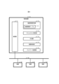
- FIG. FIG. 2 shows a hardware configuration of a control device according to an embodiment
- FIG. 4 is a diagram for explaining an overview of time-division communication according to an embodiment
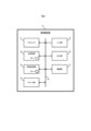
- FIG. 2 shows a functional configuration of a control device according to an embodiment
- FIG. 4 is a diagram for explaining control time according to the embodiment
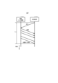
- FIG. 1 is a first diagram showing an example of acquisition time of input data according to the embodiment
- FIG. 2 shows an example of acquisition time of input data according to the embodiment;
- a diagram showing an example of transmission time of transmission data according to an embodiment Flowchart showing initialization processing according to the embodiment Flowchart showing adjustment processing according to the embodiment
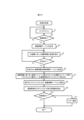
- Flowchart showing measurement processing according to the embodiment FIG. 4 is a diagram for explaining a comparison between the transmission capacity of a time slot and the size of communication data according to an embodiment;
- FIG. 4 is a diagram showing change of communication cycle according to the embodiment;
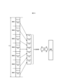
- FIG. 4 is a diagram for explaining the payload size according to the embodiment;
- control device 10 according to the embodiment of the present disclosure will be described in detail with reference to the drawings.
- Control device 10 constitutes control system 100 together with devices 21, 22, 23, and 239, as shown in FIG.
- the control system 100 corresponds to part of the FA system installed in the factory.
- This FA system may be, for example, a production system, an inspection system, a processing system, or other systems.
- the control device 10 adjusts the communication cycle of the time-division multiplex method performed with the devices 21-23.
- Network 30 is an industrial network that follows the Fieldbus standard.
- the control device 10 is a PLC (Programmable Logic Controller) or an IPC (Industrial Personal Computer) that functions as a main station on the network 30.
- Each of the devices 21 to 23 is a device functioning as a slave station to be managed by the master station.
- the device 21 is a camera that captures images of the production line, and the device 22 is a sensor installed on the production line.
- the device 23 is a PLC having a network unit 231 , a CPU (Central Processing Unit) unit 232 and an I/O (Input/Output) unit 233 which are connected to each other via a system bus 234 .
- the I/O unit 233 of the device 23 is connected to the device 239 via signal lines.
- the control device 10 controls the devices 21 to 23, 239 to operate the control system 100. For example, based on the image output from the device 21, the control device 10 moves the arm of the device 239, which is a robot connected to the device 23, to transport the work.
- the hardware configuration of the control device 10 is shown in FIG.
- the control device 10 has a processor 41 , a main storage section 42 , an auxiliary storage section 43 , a clock section 44 , an input section 45 , an output section 46 and a communication section 47 as its hardware configuration.
- the main storage section 42 , auxiliary storage section 43 , clock section 44 , input section 45 , output section 46 and communication section 47 are all connected to the processor 41 via an internal bus 48 .
- the processor 41 includes a CPU (Central Processing Unit) or MPU (Micro Processing Unit) which is an integrated circuit. By executing a program 49 stored in the auxiliary storage unit 43, the processor 41 realizes various functions of the control device 10 and executes processing described later.
- CPU Central Processing Unit
- MPU Micro Processing Unit
- the main storage unit 42 includes a RAM (Random Access Memory).
- a program 49 is loaded from the auxiliary storage unit 43 into the main storage unit 42 .
- the main storage unit 42 is used as a work area for the processor 41 .
- the auxiliary storage unit 43 includes non-volatile memory represented by EEPROM (Electrically Erasable Programmable Read-Only Memory) and HDD (Hard Disk Drive).
- EEPROM Electrically Erasable Programmable Read-Only Memory
- HDD Hard Disk Drive
- Auxiliary storage unit 43 stores various data used for processing of processor 41 in addition to program 49 .
- Auxiliary storage unit 43 supplies data used by processor 41 to processor 41 and stores the data supplied from processor 41 in accordance with instructions from processor 41 .
- the clock unit 44 includes, for example, a crystal oscillator, a silicon oscillator, a crystal oscillator, or a clock generation circuit having an oscillation circuit.
- the clock unit 44 generates and outputs a clock signal based on the clock generated by the clock generation circuit.
- the clock signal includes a clock pulse, and is used by the processor 41 to keep time by counting the number of rises of the clock pulse by built-in hardware elements or by software processing executed.
- the input unit 45 includes input devices typified by input keys and a pointing device.
- the input unit 45 acquires information input by the user of the control device 10 and notifies the processor 41 of the acquired information.
- the output unit 46 includes output devices typified by LEDs (Light Emitting Diodes), LCDs (Liquid Crystal Displays), and speakers.
- the output unit 46 presents various information to the user according to instructions from the processor 41 .
- the communication unit 47 includes a network interface circuit for transmitting and receiving Ethernet frames to and from external devices. Communication unit 47 receives a signal from the outside and outputs data indicated by this signal to processor 41 . Also, the communication unit 47 transmits a signal indicating the data output from the processor 41 to an external device.
- control device 10 and the devices 21 to 23 each communicate according to the TSN standard. An outline of communication according to this TSN standard will be described below.
- the devices 21 to 23 are collectively referred to as the device 20.
- FIG. 1 An outline of communication according to this TSN standard will be described below.
- the devices 21 to 23 are collectively referred to as the device 20.
- the control device 10 and the device 20 synchronize time via the network 30. Specifically, each of the control device 10 and the device 20 shares time with other devices by a time synchronization protocol.
- a time synchronization protocol is a protocol for synchronizing the time of devices on a communication network with high precision. For example, when IEEE802.1 AS is applied as the time synchronization protocol, a grandmaster corresponding to one node on the network periodically distributes a highly accurate reference clock via the communication network. Further, communication delay is measured by reciprocating data between the grandmaster and the slave node, and the slave node obtains a reference clock corrected for this communication delay. Thereby, the time when the communication delay is corrected is shared.
- time sharing and time synchronization by a plurality of devices means synchronizing the clocks of each of the plurality of devices. If the clocks of a plurality of devices keep the same time, and if this time is shared by the plurality of devices, the plurality of devices will synchronize the time.
- the time shared between devices is referred to as shared time.
- the control device 10 and the device 20 transmit and receive data based on a predetermined schedule according to the shared time using a protocol defined as IEEE802.1 Qbv. Specifically, as shown in FIG. 3, the control device 10 and the device 20 communicate by time-division multiplexing in communication cycles 51 and 52 each having a predetermined length according to the shared time.
- the communication cycles 51 and 52 are adjacent to each other. That is, the communication cycle 52 is provided immediately after the communication cycle 51 , and the end time of the communication cycle 51 is equal to the start time of the communication cycle 52 . Although two communication cycles 51 and 52 are shown in FIG. 3, periods equivalent to the communication cycles 51 and 52 are provided periodically before the communication cycle 51 and after the communication cycle 52, respectively.
- the communication cycles 51 and 52 respectively have adjacent time slots TS1, TS2, TS3, . . . , TS0. , TS0 are arranged in this order in the communication cycle 51 as shown in FIG. equal. Also, the end time of each time slot is equal to the start time of the next time slot. However, the end time of time slot TS0 is equal to the end time of communication cycle 51 . Immediately after the time slot TS0 of the communication cycle 51, the time slot TS1 of the communication cycle 52 is arranged.
- Each time slot is a time segment for carrying out different types of communication, and is provided for communication of a predetermined protocol, channel or format.
- time slot TS1 is a time segment for performing cyclic transmission.
- Cyclic transmission is a communication method for synchronizing the data stored in the memory at each successive cycle by periodically executing communication for storing common data in the memory of each device.
- Timeslot TS2 is a time segment for communicating according to the time synchronization protocol.
- Time slot TS3 is a time segment for communicating according to open control network protocols published for control networks.
- a protocol for a control network is a protocol that ensures that information is transmitted within a predetermined length of time by transmitting data every cycle and that devices share information in real time.
- the control network protocol corresponds to an example of the second type of communication performed by the control device 10 .
- the time slot TS0 is a time segment for communicating according to protocols for information networks that do not necessarily require punctuality. Protocols for information networks, unlike protocols for control networks, do not necessarily guarantee that information is transmitted within a certain amount of time. For example, since data is transmitted on a best effort basis in time slot TS0, if many devices transmit data in time slot TS0, the transmission time becomes long. Data loss is possible. Further, in time slot TS0, data need not be transmitted every cycle, and data may be transmitted in any cycle as needed. In time slot TS0, for example, IP (Internet Protocol) communication is performed.
- IP Internet Protocol
- the information network protocol corresponds to an example of the first type of communication performed by the control device 10 .
- the length of the time slot TS0 is, for example, the length of the time slots TS1, TS2, TS3, . It is set as the difference obtained by reducing the However, with such a setting, the length of the time slot TS0 may become excessively long with respect to the actual amount of communication, and there is room for shortening the communication cycle.
- the control device 10 according to the present embodiment has a function of adjusting the communication cycle by shortening the time slot TS0 based on the actual traffic.
- the control device 10 has, as its functions, a communication section 11 that communicates via a network 30, a device information management section 12 that acquires and manages information from the device 20, and a time slot length. It has a time slot setting unit 13 for setting, a measurement unit 14 for measuring data size and transmission time, a device control unit 15 for controlling the device 20, and a network monitoring unit 16 for monitoring the state of the network 30.
- the communication unit 11 is realized mainly by cooperation of the processor 41, the clock unit 44, and the communication unit 47.
- the communication unit 11 communicates with the device 20 via the network 30 according to the TSN standard. Specifically, as a grand master, the communication unit 11 distributes the shared time based on the time of the clock unit 44 to the device 20 and shares the shared time with the device 20 .
- the communication unit 11 may be a slave node that acquires shared time distributed from other grandmasters. Then, as shown in FIG. 3, the communication unit 11 executes communication of the type corresponding to the time slot for each communication cycle.
- the communication unit 11 determines, for each communication cycle defined by the shared time shared with the device 20 as the controlled device, the type corresponding to the time segment in each of a plurality of time segments included in the communication cycle. It corresponds to an example of communication means for executing communication of Further, the communication unit 11 executes communication instructed by the device information management unit 12, the time slot setting unit 13, and the measurement unit 14 as preparation for setting the time slot length and communication cycle.
- the device information management unit 12 is realized mainly by cooperation between the processor 41 and at least one of the main storage unit 42 and the auxiliary storage unit 43.
- the device information management unit 12 collects information for communicating with the device 20 according to the TSN standard via the communication unit 11 and writes the collected information into the device information table 121 . Further, the device information management unit 12 acquires information indicating the time slot set by the time slot setting unit 13 from the time slot setting unit 13, and acquires information indicating the result of measurement by the measurement unit 14 from the measurement unit 14. , the acquired information is written in the device information table 121 . Then, the device information management unit 12 provides the information of the device information table 121 to the outside.
- the device information table 121 as shown in FIG. "Communication attribute” indicating whether is a protocol for control network or protocol for information network, "Communication cycle allowable value” which is a value allowed as a cycle of time slots for the protocol for control network, A “transport layer protocol” indicating a designated protocol of an upper layer for IP communication, a “processing time” indicating the time required for the device 20 to complete data calculation processing, and the device 20 , the size of the input data that the control device 10 acquires from the device 20, and the time required to acquire the input data are shown in a table format in association with each other.
- the “configuration device” in the device information table 121 may be, for example, the model, model number, or address of the device 20.
- "Constituent equipment” for the equipment 23, which is a PLC indicates the configuration of the PLC including all units connected via the same bus and the equipment 239 connected to the I/O unit 233.
- FIG. 5 "PLC23" indicating the device 23 which is a PLC is "NW-U231” indicating the network unit 231, "CPU-U232” indicating the CPU unit 232, and "IO-U233” indicating the I/O unit 233. , indicating that a device 239 indicated by “DEV239” is connected to the I/O unit 233 .
- P0 indicated as “communication type” in FIG. 5 corresponds to the information network protocol as shown in FIG. 3
- P1 corresponds to cyclic transmission
- P2 corresponds to time Supports synchronous protocols
- CTR as the "communication attribute” indicates that it is a protocol for a control network
- INFO indicates that it is a protocol for an information network.
- the "permissible communication cycle value” is indicated in a different range for each protocol of the control network.
- Transport layer protocol indicates “TCP (Transmission Control Protocol)” or “UDP (User Datagram Protocol)”.
- the “processing time” is measured by the device 20 at startup.
- the “processing time” of the device 21, which is a camera is the time it takes to execute the conversion process for outputting the image to the outside after the image is captured.
- the “processing time” of the device 23, which is a PLC is the time required to optimize each unit and the device 239 connected by the bus. is the time from when is received until the movement of the arm by the device 239 is actually completed.
- the device information management unit 12 corresponds to an example of an acquisition unit that acquires type information indicating the type of communication to be executed from the controlled device in the control device 10 .
- the type information corresponds to information including "communication type”. Registration of the “allocated time slot”, “input data size” and “input data acquisition time” in the device information table 121 will be described later.
- the time slot setting unit 13 is mainly implemented by the processor 41 .
- the time slot setting unit 13 assigns the type of communication performed by the device 20 to time slots based on the “communication type” and “communication attribute” of the information collected from the device 20 .
- the time slot setting unit 13 corresponds to an example of allocation means for allocating one of the types of communication indicated by the type information to a plurality of time segments included in the communication cycle in the control device 10 .
- the time slot setting unit 13 registers the allocated time slots in the device information table 121 as shown in FIG.
- the time slot setting unit 13 sets the initial value of the length of the time slot TS0 based on the length of the time slot corresponding to the control network protocol preset by the user and the initial value of the communication cycle. set.
- the initial value of the communication cycle may be determined by the time slot setting unit 13 or by the device information management unit 12 based on the "permissible communication cycle value" in the device information table 121. good.
- the time slot setting unit 13 determines that the initial value is excessively long based on the initial value of the length of the time slot TS0 and the result of measurement by the measuring unit 14, it shortens the length of the time slot TS0. By doing so, the communication cycle is adjusted. Details of determination by the time slot setting unit 13 will be described later.
- the measurement unit 14 is realized mainly by the cooperation of the processor 41 and the clock unit 44.
- the measurement unit 14 measures the control time required to control the device 20 by communication of the type corresponding to the time slot TS0 of the control device 10, the size of the communication data transmitted in the time slot TS0 for controlling the device 20, to measure
- the control device 10 executes data processing based on input data from a device 21 as an input device, and transmits transmission data including a control command as a processing result to a device 23 as a controlled device. to change its state. Any data transmitted here follows the protocol for the information network.
- the control time T10 required for such control includes a time T11 required for acquisition of input data, a time T12 required for data processing by the control device 10, a time T13 required for transmission of the control command, and a time T13 required for the device 23 to change its state. and the time T14 until the control command is reflected.
- the control time T10 is the time during which the controlled device is controlled by communication according to the protocol for the information network without setting a time slot.
- control time T10 is the time required to control the controlled device by communication according to Specifically, when the device 20 is controlled by communication according to the TSN standard, the entire control time T10 shown in FIG. 6 is not necessarily completed within one time slot TS0, and the time T11 is and time T13 may be included in the next time slot TS0.
- the measurement unit 14 measures the times T11 to T14 and obtains the total sum to measure the control time T10.
- This control time T10 corresponds to the time required to control the device 20 in a situation in which communication according to the information network protocol is always permitted without setting a time during which data transmission is prohibited.
- the measurement unit 14 measures the times T11 and T13 based on the information notified from the devices 21 and 23. For example, as exemplified in FIG. 7, the measurement unit 14 requests sample data that is equivalent to data generated during normal operation of the device 21 and output to the outside. Upon receiving the request, the device 21 starts transmitting the sample data, and when the transmission of all the sample data to be transmitted is completed, notifies the control device 10 of the completion of transmission. The measurement unit 14 of the control device 10 may measure the time T11 from the request to the time when the transmission completion notification is received. The time T11 measured by the measuring unit 14 is registered as "input data acquisition time" in the device information table 121, as shown in FIG.
- the method for measuring the time T11 is not limited to the example in FIG. As shown in FIG. 8, the measurement unit 14 receives from the device 21 a notification of the time T11a at which the device 21 started transmitting the input data, and calculates the notified time T11a from the time T11b at which the last input data was received. Time T11 may be obtained by subtraction.
- the measurement unit 14 notifies the device 23 of the completion of processing and requests receipt of the processing result.
- the device 23 that has received the request notifies the control device 10 of acceptance of reception, and transmission of transmission data from the control device 10 is started.
- the device 23 notifies the control device 10 of the completion of reception.
- the measuring unit 14 may measure a time T13 from the start of transmission of transmission data to the time of receiving the reception completion notification. Note that the method for measuring the time T13 is not limited to the example of FIG. 9, and may be arbitrarily changed.
- the measurement unit 14 may obtain the measured value of the time T14 by referring to "processing time" in the device information table 121 shown in FIG.
- the device 23 may actually process the transmission data received as a sample, measure the time required for the processing, and notify the measuring unit 14 of the measurement result.
- the measurement unit 14 measures the size of the input data and records the measurement result as "input data size" in the device information table 121, as shown in FIG.
- the measuring unit 14 also measures the total sum of the size of the input data and the size of the transmission data as the size of the communication data.
- the length of the control time and the size of the communication data measured by the measuring unit 14 are used to adjust the communication cycle, as will be described later.
- the measurement unit 14 corresponds to an example of a measurement unit that measures the control time taken to control the controlled device when communication is executed regardless of the time segment in the control device 10 .
- the device control unit 15 is mainly implemented by the processor 41 .
- the device control unit 15 controls the device 20 to be controlled by communicating with the device 20 via the communication unit 11 according to the communication cycle adjusted by the time slot setting unit 13 and processing data.
- the device control unit 15 executes data processing for generating transmission data based on the input data in the example of FIG.
- the device control unit 15 corresponds to an example of data processing means for processing data for controlling the controlled device in the control device 10 .
- the network monitoring unit 16 is mainly realized by the processor 41.
- Network monitoring unit 16 monitors the state of network 30 to learn the relationship between the operating state of network 30 and the parameters for determining the length of time slot TS0. As the learning by the network monitoring unit 16 progresses, the length of the time slot TS0 is determined from the state of the network 30 without requiring measurement by the measuring unit 14 .
- the network monitoring unit 16 corresponds to an example of learning means for learning the communication state on the network according to the communication cycle adjusted by the time slot setting unit 13 as adjustment means in the control device 10 .
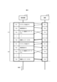
- FIG. 10 The initialization process shown in FIG. 10 starts when the control device 10 is activated.
- control device 10 executes link scanning (step S1). Specifically, the device information management unit 12 checks the device 20 connected to the control device 10 via the network 30 (step S2).
- step S2 If the connection of the device 20 cannot be confirmed by the link scan (step S2; No), the control device 10 repeats the process of step S1. On the other hand, if the connection of at least one device 20 can be confirmed by the link scan (step S2; Yes), the device information management unit 12 generates the device information table 121 (step S3) and confirms the connection.
- the individual information of the device 20 is listed in the device information table. Specifically, the information of “component device” shown in FIG. 5 is recorded for each device 20 .
- the device information management unit 12 requests transmission of device information from each device 20 whose connection has been confirmed (step S4). If there is no response to the request (step S5; No), the device information management unit 12 repeats the process of step S4. On the other hand, if there is a response to the request (step S5; Yes), the device information management unit 12 records the device information in response to the device information table 121 (step S6). As a result, the “communication type”, “communication attribute”, “communication cycle allowable value”, “transport layer protocol” and “processing time” shown in FIG. 5 are recorded for each device 20 . Note that the device 20 collects information about the device 20 itself after startup, measures the “processing time”, and responds to a request from the control device 10 with device information including the collection result and the measurement result.
- the time slot setting unit 13 assigns each communication type to a time slot by prioritizing the protocol for the control network over the protocol for the information network (step S7). Specifically, when allocating communication types to time slots, the time slot setting unit 13 assigns a control network protocol to a time slot with priority over an information network protocol. For example, when the device 20 notifies the communication type and communication attribute as shown in FIG. Later, a communication type with a communication attribute of "INFO" is assigned to the last time slot TS0.
- the time slot setting unit 13 records the time slots assigned in step S7 in the device information table 121 (step S8). This associates a time slot with the type of communication performed by each device 20 as shown in FIG.
- the time slot setting unit 13 calculates the initial values of the communication cycle and time slot length. Specifically, the time slot setting unit 13 reads out the “permissible communication cycle value” corresponding to the control network protocol recorded in the device information table 121 . When the permissible value indicates the upper limit of the permissible range as shown in FIG. 5, the time slot setting unit 13 sets the minimum permissible value among the read permissible values as the initial value of the communication cycle.
- the time slot setting unit 13 acquires the time slot length determined in advance as corresponding to the control network protocol recorded in the device information table 121 .
- This time slot length may be the time slot length determined by the control device 10 according to a predetermined procedure and stored in the memory, or may be the time slot length specified by the user.
- the time slot setting unit 13 subtracts the sum of the time slot lengths corresponding to the protocol for the control network from the initial value of the communication cycle, thereby obtaining the initial length of the time slot TS0 corresponding to the protocol for the information network. get the value.
- the lengths of the time slots TS1, TS2, . . . , TS0 are TSL1, TSL2, .
- the slot setting unit 13 calculates the initial value of TSL0 by the calculation shown in Equation (1) below.
- TSL0 PR0- ⁇ (TSLn) (1)
- the time slot setting unit 13 determines whether or not the initial value is obtained by calculation (step S10). That is, the time slot setting unit 13 determines whether or not there is an initial value that can be set. For example, if the initial value of the communication cycle is small even though there are many types of protocols for the control network, the initial value of the time slot TS0 cannot be calculated, so the determination in step S10 is negative.
- step S10 determines whether the determination in step S10 is negative (step S10; No). If the determination in step S10 is negative (step S10; No), the control device 10 notifies the user of an error (step S11) and terminates the initialization process. On the other hand, if the determination in step S10 is affirmative (step S10; Yes), the initialization process ends.
- the control device 10 starts the communication cycle adjustment process shown in FIG.
- a measurement process is executed in which the measurement unit 14 measures the control time and the communication data size (step S21).
- the measurement unit 14 requests the input device to transmit input data according to the information network protocol (step S201).
- step S202 If there is no response to this request (step S202; No), the measurement unit 14 repeats the process of step S201. On the other hand, if there is a response to the request (step S202; Yes), the measurement unit 14 measures the size of the input data transmitted from the input device (step S203) and measures the acquisition time of the input data (step S204). .
- the measurement unit 14 calculates the data transmission speed based on the input data size measured in step S203 and the input data acquisition time measured in step S204 (step S205). Specifically, the size of data transmitted per unit time is calculated by dividing the size of the input data by the acquisition time. Note that the minimum value assuming best effort transmission from a plurality of devices 20 may be calculated as the transmission rate.
- the device control unit 15 processes the input data, and the measurement unit 14 measures the processing time required for processing the input data (step S206).
- transmission data to be transmitted to the controlled device is generated, and the measurement unit 14 calculates the size of the communication data as the sum of the size of the input data and the size of the transmission data (step S208). ).
- the communication unit 11 transmits the transmission data as the processing result to the controlled device, and the measurement unit 14 measures the transmission time (step S209).
- the measuring unit 14 may obtain the measured value of the transmission time by multiplying the transmission data size by the transmission speed calculated in step S205. Also, the measurement unit 14 may measure the transmission time based on the notification from the controlled device as shown in FIG.
- the measurement unit 14 measures the state change time during which the state of the controlled device changes based on the processing result (step S210). Specifically, the measurement unit 14 may cause the controlled device to measure the time until the actual operation based on the transmission data is completed, and obtain the measurement result.
- the "processing time" collected from the device 20 may be used as the state change time.
- the measurement unit 14 calculates the total sum of the acquisition time obtained in step S204, the processing time obtained in step S206, the transmission time obtained in step S209, and the state change time obtained in step S210. Time is calculated (step S211). After that, the measurement process ends.
- the measuring unit 14 corresponds to an example of measuring means for measuring control time based on information notified from the input device and the controlled device.
- the measurement unit 14 calculates the transmission capacity of the time slot TS0 in the communication cycle included in the control time (step S21). Specifically, as shown in FIG. 13, the measuring unit 14 calculates the amount of data that can be transmitted in all the time slots TS0 of the communication cycles 1 to 7 included in the control time T10.
- the time slot setting unit 13 determines whether or not the communication data size calculated in step S208 of the measurement process is smaller than the transmission capacity of the time slot TS0 calculated in step S21 (step S22). Specifically, the time slot setting unit 13 compares the transmission capacity of the time slot TS0 with the size of the communication data, as shown on the right side of FIG.
- step S22 When it is determined that the size of the communication data is not smaller than the transmission capacity (step S22; No), the processing by the control device 10 proceeds to step S25. On the other hand, if it is determined that the size of the communication data is smaller than the transmission capacity (step S22; Yes), the time slot setting section 13 determines that the current set value indicating the length of the time slot TS0 is excessively long. Then, the communication cycle is adjusted by shortening the length of the time slot TS0 (step S23).
- the time slot setting unit 13 determines the total transmission capacity based on the size of communication data and the size of other data transmitted for purposes other than controlling the controlled device. , is determined to be unnecessary transmission capacity. Then, the length of the time slot TS0 is shortened so that the sum of transmission capacity becomes equal to the sum of the size of communication data and the size of other data. As a result, as shown in FIG. 15, the communication cycle is changed and shortened, improving real-time performance.
- the size of other data may be set in advance by the user, or may be set as a margin depending on the size of communication data. For example, 20% of the size of communication data may correspond to the size of other data.
- the time slot setting unit 13 determines that the size of communication data transmitted or received in the communication of the first type for controlling the controlled device corresponds to the first type of the communication cycle included in the control time. corresponds to an example of adjusting means for adjusting the length of the communication cycle by shortening the length of the time segment corresponding to the first type from the current set value when the data transmission capacity is smaller than the data transmission capacity in the time segment corresponding to the do.
- the time slot setting unit 13 reduces the size of the payload of the data transmitted in the time slot TS0 from the current set value in accordance with the shortening of the time slot length (step S24).
- FIG. 16 shows an IP payload size of an IP packet as an example.
- the time slot setting unit 13 reduces the payload size in the time slot TS0 whose length has been changed, within a range in which it is guaranteed that communication data and other data are stored in the payload and transmitted. Since the IP header length shown in FIG. 16 depends on the transport layer protocol, the time slot setting unit 13 determines the IP payload size based on the "transport layer protocol" recorded in the device information table 121. to change
- control device 10 notifies each device 20 of the allocation of time slots, the length of each time slot, and the communication cycle (step S25). This completes preparations for communication on the network 30 according to the adjusted communication cycle.
- control device 10 starts communication together with the device 20 according to the adjusted communication cycle (step S26). Specifically, in each time slot, the communication section 11 performs communication of the type assigned to the time slot by the time slot setting section 13 as an assignment means. In order to give priority to transmission of communication data, the control device 10 transmits other data to be transmitted in time slot TS0 on a best effort basis at timings when communication data is not transmitted.
- the network monitoring unit 16 monitors the network 30 and repeats learning of the operating state of the network 30 (step S27). Specifically, the network monitoring unit 16 learns the correlation between the transmission amount of data including communication data and other data in the time slot TS0 and the operating state of the network 30 at the time when the data is transmitted. .
- the operating state of the network 30 includes parameters for determining at least one of the size of communication data and control time, for example, the configuration of the control system 100 and the operation in which data is generated when the control system 100 is in operation. Includes conditions and transmission frequency.
- the network monitoring unit 16 Through repeated learning by the network monitoring unit 16, the relationship between the data size and the time slot length in the operating state of the control system 100 is patterned, and information indicating the correlation is accumulated in the database. As a result, when the control device 10 is activated next time, the measurement processing by the measurement unit 14 is omitted, and an appropriate time slot length can be set only by the control device 10 recognizing the connected device 20. ⁇
- the network monitoring unit 16 learns the amount of data transmitted in the time slot TS0 in addition to the communication data. You may use the learning result as the size of the data of .
- the network monitoring unit 16 records the configuration of the control system 100, the size and acquisition time of input data acquired from each device 20, and the control time.
- the length of the time slot TS0 may be predicted at the time when the connection of the device 20 is confirmed every time the device 20 is activated after the next time.
- the network monitoring unit 16 repeatedly compares the result of such prediction with the length of the time slot TS0 set by the above-described processing at the time of activation, thereby minimizing the prediction error, thereby improving the prediction accuracy.
- the time slot setting section 13 may omit the measurement of the control time and set the length of the time slot TS0 based on the prediction. As a result, the time until the control system 100 starts normal operation can be shortened.
- the time slot setting unit 13 may adjust the time slot length by automatically selecting a higher protocol for IP communication represented by TCP and UDP according to the reliability of data.
- the time slot setting unit 13 corresponds to an example of adjusting means for setting a new setting value for the length of the time segment corresponding to the first type based on the result of learning by the network monitoring unit 16 as learning means. .
- time slot setting section 13 sets the length of time slot TS0 when the size of communication data is smaller than the transmission capacity of data in time slot TS0. Adjust the length of the communication cycle by shortening the length. As a result, the communication cycle is shortened along with the time slot TS0. Therefore, real-time communication can be improved in communication on a network in which time slots corresponding to communication types are provided according to the TSN standard.
- the control device 10 adjusts the lengths of the time slots TS1, TS2, . . . corresponding to the protocol for the control network as described above.
- the control device 10 of the present embodiment the length of the time slot TS0 can be shortened to effectively improve real-time performance.
- the time slot setting unit 13 changes the payload length of the data transmitted in the time slot TS0. This makes it possible to avoid transmitting data with excessively long payloads.
- the device information management unit 12 acquires information indicating the type of communication to be executed from the controlled device, and the time slot setting unit 13 prioritizes the protocol for the control network over the protocol for the information network. and assign it to a time slot. This makes it possible to more reliably assign important protocols requiring punctuality to time slots.
- the control time includes the time required to acquire input data, the processing time required to process the input data, the time required to transmit the transmission data that is the processing result, and the time required for the controlled device to change the state based on the transmission data. including the state change time required for As a result, it is possible to obtain the time required for a series of controls from the transmission of input data to the completion of the state change of the controlled device, and to calculate the minimum necessary transmission capacity for transmitting the communication data.
- the control time required for one control is measured in the above embodiment, the present invention is not limited to this, and the average value of the control time required for one control may be measured. Moreover, the control time required for multiple times of control may be measured.
- control system 100 is not limited to the example shown in FIG. 1, and may be arbitrarily changed.
- the number of devices 20 included in control system 100 may be less than three or more than three.
- time slot allocation and communication cycle adjustment are both performed by the time slot setting unit 13
- functional components for allocating time slots and functional components for adjusting the communication cycle have been described. and may be provided separately.
- control time includes four phases as shown in FIG. 6
- the control time may be measured while omitting the input data acquisition time.
- the source of input data is one input device and the destination of transmission data is one controlled device, but the present invention is not limited to this. If there are multiple transmission sources of the input data, the time required to acquire all of the multiple pieces of input data may be measured as the acquisition time.
- the transmission time and the state change time may be measured as the time from when all of the multiple transmission data are transmitted until all the state changes of the controlled device are completed.
- the input device and the controlled device may be the same device.
- control device 10 can be realized by dedicated hardware or by a normal computer system.
- the program 49 executed by the processor 41 is stored in a computer-readable non-temporary recording medium and distributed, and the program 49 is installed in the computer to configure the device that executes the above process. be able to.
- Examples of such recording media include flexible discs, CD-ROMs (Compact Disc Read-Only Memory), DVDs (Digital Versatile Discs), and MOs (Magneto-Optical Discs).
- the program 49 may be stored in a disk device possessed by a server device on a communication network typified by the Internet, and may be superimposed on carrier waves and downloaded to a computer, for example.
- the above processing can also be achieved by starting and executing the program 49 while transferring it via a communication network.
- the above processing can also be achieved by executing all or part of the program 49 on the server device and executing the program while the computer transmits and receives information regarding the processing via a communication network.
- the functions described above are to be shared by the OS (Operating System) or by cooperation between the OS and the application, only the parts other than the OS may be stored in a medium and distributed. , or you may download it to your computer.
- control device 10 is not limited to software, and part or all of it may be realized by dedicated hardware including circuits.
- the present disclosure is suitable for a system in which each device communicates for each time segment defined by the time shared between devices.
- control system 10 control device, 11 communication unit, 12 device information management unit, 121 device information table, 13 time slot setting unit, 14 measurement unit, 15 device control unit, 16 network monitoring unit, 20 to 23, 239 devices, 231 network unit, 232 CPU unit, 233 I/O unit, 234 system bus, 30 network, 41 processor, 42 main storage unit, 43 auxiliary storage unit, 44 clock unit, 45 input unit, 46 output unit, 47 communication unit, 48 internal bus, 49 program, 51, 52 communication cycle.
Landscapes
- Engineering & Computer Science (AREA)
- Computer Networks & Wireless Communication (AREA)
- Signal Processing (AREA)
- Small-Scale Networks (AREA)
Abstract
Description
本実施の形態に係る制御装置10は、図1に示されるように、機器21,22,23,239とともに制御システム100を構成する。制御システム100は、工場に設置されるFAシステムの一部に相当する。このFAシステムは、例えば、生産システム、検査システム、又は加工システムであってもよいし、その他のシステムであってもよい。制御システム100では、制御装置10が、機器21~23との間で行う時分割多重方式の通信周期を調整する。
Claims (10)
- ネットワークを介して被制御機器を制御する制御装置であって、
前記被制御機器と共有される共有時刻により規定される通信周期毎に、前記通信周期に含まれる複数の時間区分それぞれにおいて該時間区分に対応する種別の通信を実行する通信手段と、
前記時間区分に関わらず第1の種別の通信が実行されるときに前記被制御機器の制御にかかる制御時間を計測する計測手段と、
前記被制御機器を制御するために前記第1の種別の通信において送信され又は受信される通信データのサイズが、前記制御時間に含まれる前記通信周期のうちの前記第1の種別に対応する前記時間区分におけるデータの伝送容量よりも小さい場合に、前記第1の種別に対応する前記時間区分の長さを現在の設定値から短縮することにより前記通信周期の長さを調整する調整手段と、
を備える制御装置。 - 前記第1の種別の通信は、一定の長さの時間内に情報が伝送されることが保証されないプロトコルに従う通信である、
請求項1に記載の制御装置。 - 前記調整手段は、前記第1の種別に対応する前記時間区分の長さを短縮する場合には、前記第1の種別の通信において伝送されるデータに含まれるペイロードの長さを現在の設定値より小さい値に設定する、
請求項2に記載の制御装置。 - 前記複数の時間区分は、前記第1の種別に対応する前記時間区分と、予め定められた長さの時間内に情報が伝送されることが保証されるプロトコルに従う通信の種別である第2の種別に対応する時間区分と、を含む、
請求項2又は3に記載の制御装置。 - 前記被制御機器から、実行すべき通信の種別を示す種別情報を取得する取得手段と、
前記通信周期に含まれる前記複数の時間区分に、前記種別情報により示されるいずれかの通信の種別を割り当てる割当手段と、をさらに備え、
前記割当手段は、前記第2の種別を、前記第1の種別より優先して前記時間区分に割り当て、
前記通信手段は、前記時間区分において、前記割当手段によって該時間区分に割り当てられた種別の通信を実行する、
請求項4に記載の制御装置。 - 前記被制御機器を制御するためにデータを処理するデータ処理手段、をさらに備え、
前記制御時間は、前記データ処理手段によるデータの処理に要する時間を含む、
請求項1から5のいずれか一項に記載の制御装置。 - 前記制御時間は、前記被制御機器と同一の又は異なる入力機器から入力データを取得するのに要する時間と、前記データ処理手段による前記入力データの処理に要する時間と、前記データ処理手段による処理結果を前記被制御機器に送信するのに要する時間と、前記処理結果に基づいて前記被制御機器が状態を変化させるのに要する時間と、を含み、
前記計測手段は、前記入力機器及び前記被制御機器から通知される情報に基づいて前記制御時間を計測する、
請求項6に記載の制御装置。 - 前記調整手段によって調整された通信周期に従う前記ネットワーク上の通信状態を学習する学習手段、をさらに備え、
前記調整手段は、前記学習手段による学習の結果に基づいて、前記第1の種別に対応する前記時間区分の長さの新たな設定値を設定する、
請求項1から7のいずれか一項に記載の制御装置。 - 被制御機器を制御する制御装置によって実行される通信周期調整方法であって、
通信手段が、前記被制御機器と共有される共有時刻により規定される通信周期毎に、前記通信周期に含まれる複数の時間区分それぞれにおいて該時間区分に対応する種別の通信を実行するステップと、
計測手段が、前記時間区分に関わらず第1の種別の通信を実行するときに前記被制御機器の制御にかかる制御時間を計測するステップと、
調整手段が、前記被制御機器を制御するために前記第1の種別の通信において送信され又は受信される通信データのサイズが、前記制御時間に含まれる前記通信周期のうちの前記第1の種別に対応する前記時間区分におけるデータの伝送容量よりも小さい場合に、前記第1の種別に対応する前記時間区分の長さを現在の設定値から短縮することにより前記通信周期の長さを調整するステップと、
を含む通信周期調整方法。 - 被制御機器を制御する制御装置を、
前記被制御機器と共有される共有時刻により規定される通信周期毎に、前記通信周期に含まれる複数の時間区分それぞれにおいて該時間区分に対応する種別の通信を実行する通信手段、
前記時間区分に関わらず第1の種別の通信を実行するときに前記被制御機器の制御にかかる制御時間を計測する計測手段、
前記被制御機器を制御するために前記第1の種別の通信において送信され又は受信される通信データのサイズが、前記制御時間に含まれる前記通信周期のうちの前記第1の種別に対応する前記時間区分におけるデータの伝送容量よりも小さい場合に、前記第1の種別に対応する前記時間区分の長さを現在の設定値から短縮することにより前記通信周期の長さを調整する調整手段、
として機能させるためのプログラム。
Priority Applications (4)
| Application Number | Priority Date | Filing Date | Title |
|---|---|---|---|
| PCT/JP2022/000087 WO2023132008A1 (ja) | 2022-01-05 | 2022-01-05 | 制御装置、通信周期調整方法及びプログラム |
| JP2022522659A JP7086326B1 (ja) | 2022-01-05 | 2022-01-05 | 制御装置、通信周期調整方法及びプログラム |
| CN202280086452.9A CN118489235B (zh) | 2022-01-05 | 2022-01-05 | 控制装置、通信周期调整方法以及记录介质 |
| US18/723,474 US20250055723A1 (en) | 2022-01-05 | 2022-01-05 | Control apparatus, communication cycle adjustment method, and recording medium |
Applications Claiming Priority (1)
| Application Number | Priority Date | Filing Date | Title |
|---|---|---|---|
| PCT/JP2022/000087 WO2023132008A1 (ja) | 2022-01-05 | 2022-01-05 | 制御装置、通信周期調整方法及びプログラム |
Publications (1)
| Publication Number | Publication Date |
|---|---|
| WO2023132008A1 true WO2023132008A1 (ja) | 2023-07-13 |
Family
ID=82057329
Family Applications (1)
| Application Number | Title | Priority Date | Filing Date |
|---|---|---|---|
| PCT/JP2022/000087 Ceased WO2023132008A1 (ja) | 2022-01-05 | 2022-01-05 | 制御装置、通信周期調整方法及びプログラム |
Country Status (4)
| Country | Link |
|---|---|
| US (1) | US20250055723A1 (ja) |
| JP (1) | JP7086326B1 (ja) |
| CN (1) | CN118489235B (ja) |
| WO (1) | WO2023132008A1 (ja) |
Citations (4)
| Publication number | Priority date | Publication date | Assignee | Title |
|---|---|---|---|---|
| CN104243110A (zh) * | 2014-08-25 | 2014-12-24 | 国网电力科学研究院 | 一种基于非实时应答机制的无线传感网络数据传输方法 |
| WO2021176697A1 (ja) * | 2020-03-06 | 2021-09-10 | 三菱電機株式会社 | 時分割多重通信システム、時分割多重通信方法及びプログラム |
| WO2021199191A1 (ja) * | 2020-03-30 | 2021-10-07 | 三菱電機株式会社 | 通信装置、通信システム、通信方法及びプログラム |
| JP6987323B1 (ja) * | 2021-04-26 | 2021-12-22 | 三菱電機株式会社 | 通信装置、通信方法及びプログラム |
Family Cites Families (7)
| Publication number | Priority date | Publication date | Assignee | Title |
|---|---|---|---|---|
| JP4341672B2 (ja) * | 2006-12-11 | 2009-10-07 | 沖電気工業株式会社 | 通信タイミング制御システム及び通信タイミング制御方法 |
| KR101225184B1 (ko) * | 2008-12-04 | 2013-01-22 | 한국전자통신연구원 | 슬롯을 동적으로 할당하는 방법 및 이를 수행하는 장치 |
| CN102932086B (zh) * | 2011-08-09 | 2017-06-13 | 中兴通讯股份有限公司 | 数据时分传输方法及系统 |
| CN108696298B (zh) * | 2017-04-10 | 2020-11-17 | 华为技术有限公司 | 数据传输方法及装置、电力线通信网络、电力系统 |
| US11375501B2 (en) * | 2018-11-13 | 2022-06-28 | Qualcomm Incorporated | Configuration of sidelink radio resources |
| KR101992815B1 (ko) * | 2018-12-26 | 2019-06-25 | 한화시스템(주) | Tdma 시스템에서 자원 효율을 위한 프레임 구조를 생성하는 중심 노드 및 동적 타임슬롯 할당 장치 |
| CN113612700B (zh) * | 2021-08-12 | 2023-11-14 | 北京邮电大学 | 一种低时延零抖动的混合时间敏感流量调度方法及装置 |
-
2022
- 2022-01-05 US US18/723,474 patent/US20250055723A1/en active Pending
- 2022-01-05 WO PCT/JP2022/000087 patent/WO2023132008A1/ja not_active Ceased
- 2022-01-05 JP JP2022522659A patent/JP7086326B1/ja active Active
- 2022-01-05 CN CN202280086452.9A patent/CN118489235B/zh active Active
Patent Citations (4)
| Publication number | Priority date | Publication date | Assignee | Title |
|---|---|---|---|---|
| CN104243110A (zh) * | 2014-08-25 | 2014-12-24 | 国网电力科学研究院 | 一种基于非实时应答机制的无线传感网络数据传输方法 |
| WO2021176697A1 (ja) * | 2020-03-06 | 2021-09-10 | 三菱電機株式会社 | 時分割多重通信システム、時分割多重通信方法及びプログラム |
| WO2021199191A1 (ja) * | 2020-03-30 | 2021-10-07 | 三菱電機株式会社 | 通信装置、通信システム、通信方法及びプログラム |
| JP6987323B1 (ja) * | 2021-04-26 | 2021-12-22 | 三菱電機株式会社 | 通信装置、通信方法及びプログラム |
Also Published As
| Publication number | Publication date |
|---|---|
| CN118489235A (zh) | 2024-08-13 |
| CN118489235B (zh) | 2025-09-05 |
| JP7086326B1 (ja) | 2022-06-17 |
| JPWO2023132008A1 (ja) | 2023-07-13 |
| US20250055723A1 (en) | 2025-02-13 |
Similar Documents
| Publication | Publication Date | Title |
|---|---|---|
| US12276973B2 (en) | Control system | |
| US7904184B2 (en) | Motion control timing models | |
| JP6527289B2 (ja) | 時刻同期方法、センサ収容端末、およびセンサネットワークシステム | |
| CN105049309B (zh) | 基于powerlink实时以太网的伺服驱动器同步方法 | |
| WO2015128981A1 (ja) | プログラマブルコントローラシステム、そのコントローラ | |
| JP2010220036A (ja) | ゲートウェイ装置、その制御方法、システム、制御方法を実行させるためのプログラム及びそれを記録した記録媒体 | |
| JP2009182659A (ja) | タイミング同期方法、同期装置、同期システム及び同期プログラム | |
| EP3528067A1 (en) | Computing device and control system | |
| JP7086326B1 (ja) | 制御装置、通信周期調整方法及びプログラム | |
| CN108401454B (zh) | 事务调度方法、处理器、分布式系统和无人机 | |
| US10698857B2 (en) | Systems, methods, and apparatus to synchronize data bus access | |
| JP2006148907A (ja) | 周期的に作動するコミュニケーションシステムにおける時間同期化方法 | |
| ES2265055T3 (es) | Proceso para el funcionamiento de un usuario final de un sistema de comunicacion isocrono y ciclico. | |
| JP7066080B1 (ja) | 通信制御装置、通信制御方法及びプログラム | |
| WO2022185589A1 (ja) | 情報処理装置、方法およびプログラム | |
| JPWO2021131724A5 (ja) | ||
| JP6987323B1 (ja) | 通信装置、通信方法及びプログラム | |
| WO2021131724A1 (ja) | 通信装置、通信システム、通信制御方法、及びプログラム | |
| US7330921B2 (en) | Communication control circuit and communication control method | |
| US20170117980A1 (en) | Time synchronization for network device | |
| US12463916B2 (en) | Communication apparatus, control method for communication apparatus, and storage medium | |
| JP6854991B1 (ja) | 通信装置、通信システム、通信方法及びプログラム | |
| JP7603212B2 (ja) | 通信装置、通信システム、通信制御方法、及びプログラム | |
| CN110111549B (zh) | 输入单元 | |
| JPWO2022019014A5 (ja) |
Legal Events
| Date | Code | Title | Description |
|---|---|---|---|
| WWE | Wipo information: entry into national phase |
Ref document number: 2022522659 Country of ref document: JP |
|
| 121 | Ep: the epo has been informed by wipo that ep was designated in this application |
Ref document number: 22918600 Country of ref document: EP Kind code of ref document: A1 |
|
| WWE | Wipo information: entry into national phase |
Ref document number: 18723474 Country of ref document: US |
|
| WWE | Wipo information: entry into national phase |
Ref document number: 202280086452.9 Country of ref document: CN |
|
| NENP | Non-entry into the national phase |
Ref country code: DE |
|
| 122 | Ep: pct application non-entry in european phase |
Ref document number: 22918600 Country of ref document: EP Kind code of ref document: A1 |
|
| WWG | Wipo information: grant in national office |
Ref document number: 202280086452.9 Country of ref document: CN |