WO2023127537A1 - Multilayer body, optical element and light guide element - Google Patents
Multilayer body, optical element and light guide element Download PDFInfo
- Publication number
- WO2023127537A1 WO2023127537A1 PCT/JP2022/046328 JP2022046328W WO2023127537A1 WO 2023127537 A1 WO2023127537 A1 WO 2023127537A1 JP 2022046328 W JP2022046328 W JP 2022046328W WO 2023127537 A1 WO2023127537 A1 WO 2023127537A1
- Authority
- WO
- WIPO (PCT)
- Prior art keywords
- compound
- liquid crystalline
- formula
- group
- optically anisotropic
- Prior art date
Links
Images


Classifications
-
- B—PERFORMING OPERATIONS; TRANSPORTING
- B32—LAYERED PRODUCTS
- B32B—LAYERED PRODUCTS, i.e. PRODUCTS BUILT-UP OF STRATA OF FLAT OR NON-FLAT, e.g. CELLULAR OR HONEYCOMB, FORM
- B32B27/00—Layered products comprising a layer of synthetic resin
-
- C—CHEMISTRY; METALLURGY
- C09—DYES; PAINTS; POLISHES; NATURAL RESINS; ADHESIVES; COMPOSITIONS NOT OTHERWISE PROVIDED FOR; APPLICATIONS OF MATERIALS NOT OTHERWISE PROVIDED FOR
- C09K—MATERIALS FOR MISCELLANEOUS APPLICATIONS, NOT PROVIDED FOR ELSEWHERE
- C09K19/00—Liquid crystal materials
- C09K19/04—Liquid crystal materials characterised by the chemical structure of the liquid crystal components, e.g. by a specific unit
- C09K19/06—Non-steroidal liquid crystal compounds
- C09K19/08—Non-steroidal liquid crystal compounds containing at least two non-condensed rings
- C09K19/10—Non-steroidal liquid crystal compounds containing at least two non-condensed rings containing at least two benzene rings
- C09K19/14—Non-steroidal liquid crystal compounds containing at least two non-condensed rings containing at least two benzene rings linked by a carbon chain
- C09K19/18—Non-steroidal liquid crystal compounds containing at least two non-condensed rings containing at least two benzene rings linked by a carbon chain the chain containing carbon-to-carbon triple bonds, e.g. tolans
-
- C—CHEMISTRY; METALLURGY
- C09—DYES; PAINTS; POLISHES; NATURAL RESINS; ADHESIVES; COMPOSITIONS NOT OTHERWISE PROVIDED FOR; APPLICATIONS OF MATERIALS NOT OTHERWISE PROVIDED FOR
- C09K—MATERIALS FOR MISCELLANEOUS APPLICATIONS, NOT PROVIDED FOR ELSEWHERE
- C09K19/00—Liquid crystal materials
- C09K19/04—Liquid crystal materials characterised by the chemical structure of the liquid crystal components, e.g. by a specific unit
- C09K19/06—Non-steroidal liquid crystal compounds
- C09K19/08—Non-steroidal liquid crystal compounds containing at least two non-condensed rings
- C09K19/30—Non-steroidal liquid crystal compounds containing at least two non-condensed rings containing saturated or unsaturated non-aromatic rings, e.g. cyclohexane rings
-
- C—CHEMISTRY; METALLURGY
- C09—DYES; PAINTS; POLISHES; NATURAL RESINS; ADHESIVES; COMPOSITIONS NOT OTHERWISE PROVIDED FOR; APPLICATIONS OF MATERIALS NOT OTHERWISE PROVIDED FOR
- C09K—MATERIALS FOR MISCELLANEOUS APPLICATIONS, NOT PROVIDED FOR ELSEWHERE
- C09K19/00—Liquid crystal materials
- C09K19/04—Liquid crystal materials characterised by the chemical structure of the liquid crystal components, e.g. by a specific unit
- C09K19/06—Non-steroidal liquid crystal compounds
- C09K19/34—Non-steroidal liquid crystal compounds containing at least one heterocyclic ring
-
- C—CHEMISTRY; METALLURGY
- C09—DYES; PAINTS; POLISHES; NATURAL RESINS; ADHESIVES; COMPOSITIONS NOT OTHERWISE PROVIDED FOR; APPLICATIONS OF MATERIALS NOT OTHERWISE PROVIDED FOR
- C09K—MATERIALS FOR MISCELLANEOUS APPLICATIONS, NOT PROVIDED FOR ELSEWHERE
- C09K19/00—Liquid crystal materials
- C09K19/04—Liquid crystal materials characterised by the chemical structure of the liquid crystal components, e.g. by a specific unit
- C09K19/38—Polymers
-
- G—PHYSICS
- G02—OPTICS
- G02B—OPTICAL ELEMENTS, SYSTEMS OR APPARATUS
- G02B5/00—Optical elements other than lenses
- G02B5/18—Diffraction gratings
-
- G—PHYSICS
- G02—OPTICS
- G02B—OPTICAL ELEMENTS, SYSTEMS OR APPARATUS
- G02B5/00—Optical elements other than lenses
- G02B5/30—Polarising elements
Definitions
- the present invention relates to laminates, optical elements, and light guide elements.
- Patent Document 1 an optical element capable of obtaining diffracted light with a large diffraction angle and high diffraction efficiency is composed of a cured layer of a liquid crystalline composition containing a tolan compound as a liquid crystalline compound, and a predetermined liquid crystal
- An optical element with an optically anisotropic layer having an orientation pattern is disclosed.
- the present inventors produced and examined the optical element described in Patent Document 1, and found that a liquid crystalline composition containing a tolan compound exhibits a high refractive index anisotropy ⁇ n, and a cured product of this liquid crystalline composition.
- the optical element provided with the optically anisotropic layer has a high diffraction efficiency, it is difficult to maintain the above optical properties due to photodegradation of the tolane compound (in other words, the diffraction efficiency is reduced due to photodegradation of the tolane compound. may be significantly reduced). In other words, it has been clarified that there is room for improving the light resistance of the optical element.
- this invention makes it a subject to provide the laminated body which is excellent in light resistance.
- Another object of the present invention is to provide an optical element and a light guide element having the laminate.
- an optically anisotropic layer comprising a cured layer of a composition containing a liquid crystalline compound; A laminate having a pair of oxygen barrier layers disposed on both sides of the optically anisotropic layer, The optically anisotropic layer has a liquid crystal orientation pattern in which the orientation of the optical axis derived from the liquid crystalline compound is continuously changed along at least one in-plane direction,
- the composition contains a compound having a partial structure represented by formula (I) described later, The composition contains a compound having a partial structure represented by the above formula (I) as the liquid crystalline compound, or the composition is a compound represented by the above formula (I) as a compound that is not the liquid crystalline compound.
- the composition contains, as the liquid crystalline compound, only a compound having a partial structure represented by the formula (I), or The composition further contains, as the liquid crystalline compound, another liquid crystalline compound having a structure different from the compound having the partial structure represented by the formula (I), and is represented by the formula (I).
- the content of the compound having a partial structure is 50% by mass or more with respect to the total content of the compound having a partial structure represented by the formula (I) and the other liquid crystalline compound, [2]- [4] The laminate according to any one of [4].
- the composition contains only the compound having the partial structure represented by the formula (I) as the liquid crystalline compound, the Hansen solubility parameter of the main component contained in the oxygen barrier layer and the optical difference
- the distance ⁇ HSP from the Hansen solubility parameter of the compound having the partial structure represented by the above formula (I) contained in the anisotropic layer is greater than 3.5 MPa 0.5
- the composition includes a compound having a partial structure represented by the formula (I) as a compound other than the liquid crystalline compound, and a compound having the partial structure represented by the formula (I);
- the content of the compound having the partial structure represented by formula (I) is relative to the total content of the compound having the partial structure represented by formula (I) and the other liquid crystalline compound , 50% by mass or more, the laminate according to [8].
- the value obtained by dividing the oxygen permeability coefficient [cm 3 cm/(cm 2 s mmHg)] at 25°C and 50% RH by the film thickness [ ⁇ m] is The laminate according to any one of [1] to [15], which is 1.0 ⁇ 10 ⁇ 13 or less.
- [19] further comprising a water vapor barrier layer having a water vapor permeability of 100 g/(m 2 day) or less at 40° C. and 90% RH;
- An optical element comprising the laminate according to any one of [1] to [19].
- a light guide element including the optical element according to [20] and a light guide plate.
- the laminated body excellent in light resistance can be provided. Further, according to the present invention, it is possible to provide an optical element and a light guide element having the laminate.
- FIG. 2 is a schematic diagram of an optically anisotropic layer included in the laminate shown in FIG. 1.
- FIG. 2 is a schematic plan view of an optically anisotropic layer included in the laminate shown in FIG. 1.
- FIG. 3 is a conceptual diagram showing the action of the optically anisotropic layer shown in FIG. 2;
- FIG. 3 is a conceptual diagram showing the action of the optically anisotropic layer shown in FIG. 2;
- 2 is a schematic diagram showing another example of an optically anisotropic layer included in the laminate shown in FIG. 1.
- FIG. 2 is a schematic diagram showing another example of an optically anisotropic layer included in the laminate shown in FIG. 1.
- FIG. 1 is a schematic diagram showing another example of an optically anisotropic layer included in the laminate shown in FIG. 1.
- (meth)acryloyloxy group is a notation representing both an acryloyloxy group and a methacryloyloxy group
- “(meth)acrylate” is a notation representing both acrylate and methacrylate.
- a description that does not describe substitution or unsubstituted includes a group having a substituent as well as a group having no substituent.
- an "alkyl group” includes not only an alkyl group having no substituent (unsubstituted alkyl group) but also an alkyl group having a substituent (substituted alkyl group).
- substituent when simply referred to as a "substituent", the substituent includes, for example, the following substituent L.
- substituent L examples include an alkyl group having 1 to 10 carbon atoms, an alkoxy group having 1 to 10 carbon atoms, an alkylamino group having 1 to 10 carbon atoms, an alkylthio group having 1 to 10 carbon atoms, and an alkylthio group having 1 to 10 carbon atoms.
- alkanoyl group alkanoyl group, alkanoyloxy group having 1 to 10 carbon atoms, alkanoylamino group having 1 to 10 carbon atoms, alkanoylthio group having 1 to 10 carbon atoms, alkyloxycarbonyl group having 2 to 10 carbon atoms, 2 to 10 carbon atoms
- Substituent L also includes a group substituted with CH— or —C ⁇ C—.
- the above group has two or more —CH 2 —, one —CH 2 — is replaced by —O—, and the adjacent one —CH 2 — is replaced by —CO—, resulting in an ester group ( -O-CO-) may be formed.
- the group described as the substituent L has a hydrogen atom
- at least one of the hydrogen atoms contained in the group is replaced with at least one selected from the group consisting of a fluorine atom and a polymerizable group.
- group is also included in the substituent L.
- the polymerizable group include an ethylenically unsaturated group and a ring-polymerizable group, among which substituents selected from polymerizable groups P described later are preferable.
- substituent L examples include, among others, an alkyl group having 1 to 10 carbon atoms, an alkoxy group having 1 to 10 carbon atoms, an alkanoyl group having 1 to 10 carbon atoms, an alkanoyloxy group having 1 to 10 carbon atoms, and a alkanoyloxy group having 1 to 10 carbon atoms.
- alkyloxycarbonyl group trifluoromethyl group, hydroxy group, carboxy group, cyano group, nitro group, or halogen atom
- alkyl group having 1 to 10 carbon atoms alkoxy group having 1 to 10 carbon atoms, carbon number 2 to 10 alkanoyl groups, alkanoyloxy groups having 2 to 10 carbon atoms, alkyloxycarbonyl groups having 2 to 10 carbon atoms, trifluoromethyl groups, or halogen atoms are more preferable, alkyl groups having 1 to 6 carbon atoms, carbon More preferred are an alkoxy group having 1 to 6 carbon atoms, an alkanoyl group having 2 to 6 carbon atoms, an alkanoyloxy group having 2 to 6 carbon atoms, an alkyloxycarbonyl group having 2 to 6 carbon atoms, a trifluoromethyl group, or a fluorine atom.
- the polymerizable group when simply referred to as a "polymerizable group", includes, for example, the following polymerizable group P.
- Polymerizable group P examples include groups represented by any one of the following formulas (P-1) to (P-19).
- * in the following formula represents a bonding position
- Me represents a methyl group
- Et represents an ethyl group.
- formula (P-1) or formula (P-2) ((meth)acryloyloxy group) is preferable.
- the "solid content" of the composition means a component that forms a composition layer formed using the composition, and when the composition contains a solvent (organic solvent, water, etc.) , means all components except solvent.
- a liquid component is also regarded as a solid content.
- the thickness of the layer is measured at 10 points by observing a cross section cut by a microtome with a SEM (scanning electron microscope) or a TEM (transmission electron microscope). It is a value using the average value.
- the laminate of the present invention is an optically anisotropic layer comprising a cured layer of a composition containing a liquid crystalline compound; A laminate having a pair of oxygen barrier layers disposed on both sides of the optically anisotropic layer, The optically anisotropic layer has a liquid crystal orientation pattern in which the orientation of the optical axis derived from the liquid crystalline compound is continuously changed along at least one in-plane direction,
- the composition contains a compound having a partial structure represented by formula (I) described below (hereinafter also referred to as a "specific tolan compound"),
- the composition contains the above specific tolan compound as the liquid crystalline compound, or the composition contains the above specific tolan compound as a compound that is not the liquid crystalline compound,
- the oxygen permeability coefficient of the oxygen barrier layer at 25° C. and 50% RH is 1.0 ⁇ 10 ⁇ 11 cm 3 ⁇ cm/(cm 2 ⁇ s ⁇ mmHg) or less.
- compositions contains the above-described specific tolan compound as a liquid crystalline compound corresponds to the case where the liquid crystalline composition is a liquid crystalline composition in any one of the first mode and the second mode described later.
- the case where the composition contains the above-described specific tolan compound as a compound that is not a liquid crystalline compound corresponds to the case where the liquid crystalline composition is the liquid crystalline composition of the third aspect described later.
- the laminate of the present invention having the above structure includes an optically anisotropic layer made of a cured liquid crystalline composition containing a tolan compound, it has a high diffraction efficiency, and at the same time, a high diffraction efficiency is maintained over a long period of time due to suppression of photodegradation. Diffraction efficiency can be maintained (in other words, excellent light resistance).
- an optically anisotropic layer made of a cured liquid crystalline composition containing a tolane compound exhibits photodegradation of the tolane compound caused by singlet oxygen generated by light irradiation (for example, oxidation and radical (decomposition, etc.) reduces the diffraction efficiency.
- the laminate of the present invention comprises an oxygen barrier layer having a predetermined oxygen permeability coefficient on both sides of the optically anisotropic layer. The generation of singlet oxygen is suppressed, and as a result, it is considered to be excellent in light resistance.
- the laminate of the present invention when at least one of the oxygen barrier layers arranged on both sides of the optically anisotropic layer is arranged so as to be in direct contact with the optically anisotropic layer, the light resistance of the laminate It is also clear that the performance can be further improved.
- the Hansen solubility parameter (HSP) value of the main component of the oxygen barrier layer and the liquid crystalline composition forming the optically anisotropic layer By increasing the distance ⁇ HSP from the average HSP value of the specific tolane compound and other liquid crystalline compounds in the optically anisotropic layer, the specific tolane compound and other liquid crystalline compounds (particularly, , specific tolan compounds and other liquid crystalline compounds) are suppressed from moving to the oxygen barrier layer, and as a result, the light resistance of the laminate can be further improved.
- more excellent light resistance of the laminate and/or more excellent durability (wet heat durability) of the laminate may also be referred to as "excellent effects of the present invention.
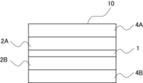
- FIG. 1 is a schematic cross-sectional view showing an example of an embodiment of the laminate of the present invention.
- the laminate 10 comprises an optically anisotropic layer 1, a pair of oxygen barrier layers 2A and 2B disposed on both sides of the optically anisotropic layer 1 (both sides of the main surface of the optically anisotropic layer), and oxygen barrier layers A water vapor barrier layer 4A arranged on the side opposite to the optically anisotropic layer 1 side of 2A and a water vapor barrier layer 4B arranged on the side opposite to the optically anisotropic layer 1 side of the oxygen barrier layer 2B.
- the oxygen permeability coefficient of each of the oxygen barrier layers 2A and 2B at 25° C.
- the optically anisotropic layer 1 is an optically anisotropic layer composed of a cured layer of a composition containing a liquid crystalline compound, and the orientation of the optical axis derived from the liquid crystalline compound is continuous along at least one in-plane direction. It has a liquid crystal alignment pattern that is randomly rotated.
- the optically anisotropic layer 1 and the oxygen barrier layer 2A, and the optically anisotropic layer 1 and the oxygen barrier layer 2B are in direct contact with each other without intervening other layers.
- Intermediate layers such as an alignment film, a pressure-sensitive adhesive layer, and an adhesive layer may be interposed between the anisotropic layer 1 and at least one of the oxygen barrier layers 2A and 2B.
- the alignment film may be an alignment film used for the purpose of forming the liquid crystalline compound in a predetermined alignment pattern in the preparation of the optically anisotropic layer 1 described later.
- the optically anisotropic layer 1 and the oxygen barrier layer 2A, and the optically anisotropic layer 1 and the oxygen barrier layer 2B are in direct contact with each other without any other layer interposed therebetween, because the effects of the present invention are more excellent.
- the water vapor barrier layer 4A is arranged on the side opposite to the optically anisotropic layer 1 of the oxygen barrier layer 2A, and the water vapor barrier layer 4B is arranged on the side opposite to the optically anisotropic layer 1 of the oxygen barrier layer 2B.
- the water vapor barrier layers 4A and 4B may not be arranged. Alternatively, only one of the vapor barrier layers 4A and 4B may be arranged.
- the optically anisotropic layer 1 is an optically anisotropic layer comprising a cured layer of a composition containing a liquid crystalline compound.
- 2 and 3 show schematic cross-sectional views of the optically anisotropic layer 1.
- FIG. 2 is a side view schematically showing the optically anisotropic layer 1
- FIG. 3 is a plan view schematically showing the liquid crystal alignment pattern of the optically anisotropic layer 1 shown in FIG.
- the sheet surface of the sheet-shaped optically anisotropic layer 1 is defined as the xy plane, and the thickness direction is defined as the z direction.
- the optically anisotropic layer 1 shown in FIG. 2 consists of a cured layer of a composition containing a liquid crystalline compound.
- the optically anisotropic layer 1 has a liquid crystal alignment pattern (one cycle length ⁇ ) in which the direction of the optic axis derived from the liquid crystal compound 30 is continuously rotated along at least one in-plane direction. 2 to 5, in order to simplify the drawings and clearly show the structure of the optically anisotropic layer 1, only the liquid crystal molecules existing on one main surface side of the optically anisotropic layer 1 are shown. ing.
- the optically anisotropic layer 1 has a structure in which oriented liquid crystalline compounds 30 are stacked, like an optically anisotropic layer formed using a composition containing a normal liquid crystalline compound.
- the optically anisotropic layer 1 functions as a general ⁇ /2 plate when the in-plane retardation value is set to ⁇ /2, that is, It has a function of giving a phase difference of half a wavelength, that is, 180° to two linearly polarized light components orthogonal to each other.
- the optically anisotropic layer 1 has an optical axis 30A derived from a liquid crystalline compound 30 (hereinafter sometimes abbreviated as "optical axis 30A") in the plane of the optically anisotropic layer 1. ) has a liquid crystal orientation pattern that changes while continuously rotating in one direction.
- optical axis 30A one direction in which the optical axis 30A rotates is aligned with the x-axis direction on the xy plane.
- one direction in which the optical axis 30A rotates is defined as the x direction.
- the optical axis 30A derived from the liquid crystalline compound 30 is the axis with the highest refractive index in the liquid crystalline compound 30, the so-called slow axis. As shown in FIG. 2, when the liquid crystalline compound 30 is a rod-like liquid crystalline compound, the optic axis 30A is along the long axis direction of the rod shape.
- That the direction of the optic axis 30A changes while continuously rotating in the x direction specifically means that the optic axis 30A of the liquid crystalline compound 30 arranged along the x direction and the x direction
- the angle formed varies depending on the position in the x direction, meaning that the angle formed by the optical axis 30A and the x direction gradually changes from ⁇ to ⁇ +180° or ⁇ 180° along the x direction. do.
- the angle gradually changes may mean that the angle changes at regular angular intervals, or may mean that the angle changes continuously.
- the difference in angle between the optical axes 30A of the liquid crystal compounds 30 adjacent to each other in the x direction is preferably 45° or less, more preferably 15° or less, and still more preferably a smaller angle. .
- the liquid crystalline compound 30 forming the optically anisotropic layer 1 has a , liquid crystalline compounds 30 having the same optical axis 30A are arranged at regular intervals.
- the angles formed by the directions of the optical axes 30A and the x direction are equal between the liquid crystal compounds 30 arranged in the y direction.
- the optical axis of the liquid crystal compound 30 is changed in the x direction in which the direction of the optical axis 30A rotates continuously within the plane.
- the length (distance) by which 30A is rotated by 180° is defined as the length ⁇ of one cycle in the liquid crystal alignment pattern.
- the length of one cycle in the liquid crystal alignment pattern is defined by the distance from ⁇ to ⁇ +180° formed by the optical axis 30A of the liquid crystal compound 30 and the x direction.
- the distance between the centers in the x direction of two liquid crystalline compounds 30 whose x direction and the direction of the optical axis 30A match is defined as the length of one cycle ⁇ (hereinafter It is sometimes called “one period ⁇ ” or “period ⁇ ”).
- the liquid crystal alignment pattern of the optically anisotropic layer 1 is a pattern in which the liquid crystal alignment of one period ⁇ is repeated in the x direction.
- the liquid crystal compounds 30 arranged in the y direction have the same angle between the optic axis 30A and the x direction in which the directions of the optical axes of the liquid crystal compounds 30 rotate.
- a region R is defined as a region in which the liquid crystalline compound 30 having the same angle formed by the optical axis 30A and the x direction is arranged in the y direction.
- the value of the in-plane retardation (Re) in each region R is half the wavelength of the light to be diffracted by the optically anisotropic layer (hereinafter referred to as "target light”), i.e., the wavelength of the target light is ⁇ .
- the in-plane retardation Re is preferably ⁇ /2. These in-plane retardations are calculated from the product of the refractive index anisotropy ⁇ n of the region R and the thickness (film thickness) d of the optically anisotropic layer.
- the refractive index difference associated with the refractive index anisotropy of the region R in the optically anisotropic layer is the refractive index in the direction of the slow axis in the plane of the region R and the direction orthogonal to the direction of the slow axis is the refractive index difference defined by the difference from the refractive index of That is, the refractive index difference ⁇ n associated with the refractive index anisotropy of the region R is the refractive index of the liquid crystalline compound 30 in the direction of the optical axis 30A and the liquid crystalline compound 30 in the direction perpendicular to the optical axis 30A in the plane of the region R. equal to the difference in refractive index of 30. That is, the refractive index difference ⁇ n depends on the liquid crystalline compound, and the in-plane retardation of each region R is substantially the same. However, as described above, the directions of the optical axes 30A differ between the regions R.
- the absolute phase changes according to the direction of the optical axis 30 A of each liquid crystalline compound 30 .
- the orientation of the optical axis 30A changes while rotating along the x-direction
- the amount of change in the absolute phase of the incident light L1 differs depending on the orientation of the optical axis 30A.
- the liquid crystal alignment pattern formed on the optically anisotropic layer 1 is a periodic pattern in the x direction
- the incident light L 1 passing through the optically anisotropic layer 1 has a pattern as shown in FIG. , a periodic absolute phase Q1 is given in the x-direction corresponding to the orientation of each optical axis 30A.
- the transmitted light L2 is refracted so as to be inclined in a direction perpendicular to the equal phase plane E1, and travels in a direction different from the traveling direction of the incident light L1 .
- the incident light L 1 of left-hand circularly polarized light P L is converted into the transmitted light L 2 of right-handed circularly polarized light P R which is tilted in the x-direction with respect to the incident direction by a certain angle.
- the amount of change in the absolute phase of the incident light L4 differs depending on the direction of the optical axis 30A. Furthermore, since the liquid crystal alignment pattern formed on the optically anisotropic layer 1 is a periodic pattern in the x-direction, the incident light L 4 that has passed through the optically anisotropic layer 1 has the following characteristics, as shown in FIG. A periodic absolute phase Q2 is given in the x-direction corresponding to the orientation of each optical axis 30A.
- the incident light L 4 is right-handed circularly polarized light P R
- the periodic absolute phase Q2 in the x-direction corresponding to the direction of the optical axis 30A is left-handed circularly polarized light P L .
- the incident light L4 forms an equiphase surface E2 inclined in the x-direction opposite to the incident light L1 . Therefore, the incident light L4 is refracted so as to be inclined in a direction perpendicular to the equal phase plane E2, and travels in a direction different from the traveling direction of the incident light L4 . In this way, the incident light L4 is converted into left-handed circularly polarized transmitted light L5 which is tilted by a certain angle in the direction opposite to the x-direction with respect to the incident direction.
- the in-plane retardation value is preferably half the wavelength of the target light. This is because the closer the in-plane retardation value is to the half wavelength of the target light, the higher the diffraction efficiency in the diffraction of the target light.
- the angles of refraction of the transmitted lights L 2 and L 5 can be adjusted. Specifically, the shorter the period ⁇ of the liquid crystal alignment pattern, the stronger the interference between the lights passing through the liquid crystal compounds 30 adjacent to each other, so that the transmitted lights L 2 and L 5 can be greatly refracted. Furthermore, by reversing the direction of rotation of the optical axis 30A of the liquid crystal compound 30 rotating along the x-direction, the direction of refraction of transmitted light can be reversed.
- the period ⁇ is preferably 50 ⁇ m or less, more preferably 25 ⁇ m or less, and even more preferably 5 ⁇ m or less.
- the film thickness d of the optically anisotropic layer 1 may be appropriately set in order to obtain a desired in-plane retardation. It is more preferably 5 ⁇ m or less.
- the thickness d is preferably as small as possible. As the film thickness d is smaller, the accuracy of forming the photo-alignment pattern can be improved.
- ⁇ /d is preferably 1 or more.
- the period ⁇ of the liquid crystal alignment pattern in the optically anisotropic layer 1 is determined from the period of the light and dark by observing the light and dark periodic patterns of the bright and dark areas under crossed Nicols conditions with a polarizing microscope. Twice the period of the observed light-dark periodic pattern corresponds to the period ⁇ of the liquid crystal orientation pattern. Also, the film thickness d of the optically anisotropic layer 1 can be measured, for example, by observing the cross section of the optically anisotropic layer with a scanning electron microscope.
- the optically anisotropic layer 1 preferably has a refractive index anisotropy ⁇ n of 0.21 or more at a wavelength of 550 nm.
- the upper limit is not particularly limited, it is preferably 0.80 or less.
- the optically anisotropic layer 1 is a cured layer of a composition containing a liquid crystalline compound (liquid crystalline composition).
- the liquid crystalline composition for forming the optically anisotropic layer 1 will be described in detail below.
- liquid crystalline composition contains only a specific tolan compound as a liquid crystalline compound.
- the liquid crystalline composition contains, as liquid crystalline compounds, a specific tolan compound and a liquid crystalline compound having a structure different from that of the specific tolan compound (hereinafter also referred to as "another liquid crystalline compound").
- the liquid crystalline composition contains a specific tolan compound as a non-liquid crystalline compound, and a liquid crystalline compound (another liquid crystalline compound) having a structure different from that of the specific tolan compound as a liquid crystalline compound.
- the liquid crystalline compound having a structure different from that of the specific tolan compound is a liquid crystalline compound that does not contain the partial structure represented by the above formula (I).
- the liquid crystalline composition of the first aspect does not contain other liquid crystalline compounds having a structure different from that of the specific tolan compound.
- a specific tolan compound exhibiting liquid crystallinity may be referred to as a "specific tolan compound with liquid crystallinity”
- a specific tolan compound not exhibiting liquid crystallinity may be referred to as a "non-liquid crystal specific tolan compound”.
- the liquid crystalline composition of the first aspect described above contains only the specific liquid crystalline tolan compound as the liquid crystalline compound.
- the liquid crystalline composition of the second aspect described above contains a liquid crystalline specific tolan compound and other liquid crystalline compounds.
- the liquid crystalline composition of the third aspect described above contains a non-liquid crystalline specific tolan compound and another liquid crystalline compound.
- liquid crystalline composition each component in the liquid crystalline composition will be described below.
- the liquid crystalline composition may further contain various components such as a polymerization initiator to be described later.
- the liquid crystalline composition contains a compound (specific tolan compound) having a partial structure represented by formula (I) below.
- a 1 and A 2 each independently represent an optionally substituted aromatic hydrocarbon ring group or aromatic heterocyclic group. * represents a binding position.
- the aromatic hydrocarbon ring group may have a monocyclic structure or a polycyclic structure.
- the aromatic hydrocarbon ring group is not particularly limited, but is preferably an arylene group, more preferably an arylene group having 6 to 20 carbon atoms, more preferably an arylene group having 6 to 10 carbon atoms, and particularly preferably a phenylene group or a naphthylene group. .
- the aromatic heterocyclic group may have a monocyclic structure or a polycyclic structure. Among them, the aromatic heterocyclic group is preferably a 5- or 6-membered monocyclic aromatic heterocyclic group.
- the heteroatom contained in the aromatic heterocyclic group is not particularly limited, and examples thereof include nitrogen atom, oxygen atom, sulfur atom and the like.
- the aromatic heterocyclic group is not particularly limited, but is preferably a heteroarylene group, more preferably a heteroarylene group having 3 to 20 carbon atoms, and still more preferably a heteroarylene group having 3 to 10 carbon atoms.
- the heteroatom contained in the heteroarylene group is preferably at least one selected from the group consisting of a nitrogen atom, an oxygen atom and a sulfur atom.
- the substituents that the aromatic hydrocarbon ring group and the aromatic heterocyclic group may have are not particularly limited, but substituents selected from the substituents L described above are preferable.
- the specific tolan compound may or may not exhibit liquid crystallinity.
- liquid crystalline compounds can be classified into a rod-like type and a disk-like type according to their shape. Furthermore, there are low-molecular-weight and high-molecular-weight types, respectively.
- Polymers generally refer to those having a degree of polymerization of 100 or more (Polymer Physics: Phase Transition Dynamics, Masao Doi, p. 2, Iwanami Shoten, 1992).
- the specific tolane compound with liquid crystallinity may be any of the compounds described above, but a rod-like liquid crystalline compound is particularly preferable.
- the liquid crystalline specific tolan compound is preferably a liquid crystalline compound having a polymerizable group in the molecule (hereinafter also referred to as "polymerizable liquid crystalline compound").
- the polymerizable group include an ethylenically unsaturated group and a ring-polymerizable group. Specifically, for example, it is selected from a vinyl group, a styryl group, an allyl group, and the polymerizable group P described above. A substituent etc. are mentioned.
- the specific liquid crystalline tolan compound has a polymerizable group, it is preferred that one molecule has two or more polymerizable groups in order to fix the alignment.
- the molecular weight of the specific tolan compound is, for example, preferably 200 to 100,000, more preferably 300 to 10,000, even more preferably 400 to 2,500.
- the above molecular weight means a weight average molecular weight.
- P 1 and P 2 each independently represent a hydrogen atom, a halogen atom, —CN, —NCS, or a polymerizable group.
- P 1 and P 2 are each independently preferably a polymerizable group.
- the polymerizable group is not particularly limited, but includes, for example, an ethylenically unsaturated group and a ring-polymerizable group, and is preferably a substituent selected from the polymerizable groups P described above.
- Sp 1 and Sp 2 each independently represent a single bond or a divalent linking group.
- Sp 1 and Sp 2 represent a divalent linking group containing at least one group selected from the group consisting of an aromatic hydrocarbon ring group, an aromatic heterocyclic group, and an aliphatic hydrocarbon ring group. do not have.
- the divalent linking group represented by Sp 1 and Sp 2 is not particularly limited, but an alkylene group (preferably an alkylene group having 1 to 20 carbon atoms), an alkenylene group (preferably an alkenylene group having 2 to 20 carbon atoms ), -O-, -S-, -CO-, -SO-, -SO2- , -COO-, -OCO-, -CO-S-, -S-CO-, -O-CO-O- , or a divalent linking group in which a plurality of these are combined is preferred.
- an alkylene group preferably an alkylene group having 1 to 20 carbon atoms
- an alkenylene group preferably an alkenylene group having 2 to 20 carbon atoms
- -O-, -S-, -CO- preferably an alkenylene group having 2 to 20 carbon atoms
- -O-, -S-, -CO- preferably an alkenylene group having 2 to 20 carbon atom
- Sp 1 and Sp 2 are each independently a single bond, or an alkylene group having 1 to 10 carbon atoms, -O-, -S-, -CO-, -COO-, -OCO-, or A divalent linking group combining a plurality of these is preferred, and a single bond, or an alkylene group having 1 to 6 carbon atoms, -O-, -S-, or a divalent linking group combining a plurality of these is more preferred.
- a single bond, an alkylene group having 1 to 4 carbon atoms, —O—, —S—, or a divalent linking group combining a plurality of these is more preferable.
- Z 1 and Z 2 each independently represent a single bond or a divalent linking group.
- the multiple Z 1 and the multiple Z 2 may be the same or different.
- Z 1 and Z 2 represent a divalent linking group containing at least one group selected from the group consisting of an aromatic hydrocarbon ring group, an aromatic heterocyclic group, and an aliphatic hydrocarbon ring group. do not have.
- the divalent linking group represented by Z 1 and Z 2 is not particularly limited, but an alkylene group (preferably an alkylene group having 1 to 20 carbon atoms), an alkenylene group (preferably an alkenylene group having 2 to 20 carbon atoms ), an alkynylene group (preferably an alkynylene group having 2 to 20 carbon atoms), -O-, -S-, -CO-, -SO-, -SO 2 -, -COO-, -OCO-, -CO-S -, -S-CO-, -O-CO-O-, or a divalent linking group combining a plurality of these is preferred.
- an alkylene group preferably an alkylene group having 1 to 20 carbon atoms
- an alkenylene group preferably an alkenylene group having 2 to 20 carbon atoms
- an alkynylene group preferably an alkynylene group having 2 to 20 carbon atoms
- R represents a hydrogen atom or an alkyl group having 1 to 10 carbon atoms.
- R is preferably a hydrogen atom or an alkyl group having 1 to 6 carbon atoms, more preferably a hydrogen atom or an alkyl group having 1 to 4 carbon atoms, and still more preferably a hydrogen atom.
- R may each be same or different.
- Z 1 and Z 2 are each independently -CHRCHR-, -OCHR-, -CHRO-, -COO-, -OCO-, -CO-NH-, -NH-CO-, or - C ⁇ C- is preferred, and -CHRCHR-, -OCHR-, -CHRO- or -C ⁇ C- is more preferred.
- a 1 and A 2 each independently represent an optionally substituted aromatic hydrocarbon ring group or aromatic heterocyclic group.
- a 1 and A 2 have the same meanings as A 1 and A 2 in formula (I), and the preferred embodiments are also the same.
- B 1 and B 2 each independently represent an optionally substituted aromatic hydrocarbon ring group, aromatic heterocyclic group, or aliphatic hydrocarbon ring group.
- the plurality of B 1 's and the plurality of B 2 's may be the same or different.
- the aromatic hydrocarbon ring group may have a monocyclic structure or a polycyclic structure.
- the aromatic hydrocarbon ring group is not particularly limited, but is preferably an arylene group, more preferably an arylene group having 6 to 20 carbon atoms, more preferably an arylene group having 6 to 10 carbon atoms, and particularly preferably a phenylene group or a naphthylene group. .
- the aromatic heterocyclic group may have a monocyclic structure or a polycyclic structure. Among them, the aromatic heterocyclic group is preferably a 5- or 6-membered monocyclic aromatic heterocyclic group.
- the heteroatom contained in the aromatic heterocyclic group is not particularly limited, and examples thereof include a nitrogen atom, an oxygen atom, a sulfur atom and the like.
- the aromatic heterocyclic group is not particularly limited, but is preferably a heteroarylene group, more preferably a heteroarylene group having 3 to 20 carbon atoms, and still more preferably a heteroarylene group having 3 to 10 carbon atoms.
- the heteroatom contained in the heteroarylene group is preferably at least one selected from the group consisting of a nitrogen atom, an oxygen atom and a sulfur atom.
- the aliphatic hydrocarbon ring group may have a monocyclic structure or a polycyclic structure.
- the aliphatic hydrocarbon ring group is not particularly limited and includes, for example, a cycloalkylene group.
- a cycloalkylene group having 3 to 20 carbon atoms is preferable, and a cycloalkylene group having 3 to 10 carbon atoms is more preferable.
- the substituent that the aromatic hydrocarbon ring group, the aromatic heterocyclic group, and the aliphatic hydrocarbon ring group may have is not particularly limited, but a substituent selected from the substituent L described above It is preferable to have
- n and m each independently represent an integer of 0-4. n and m preferably each independently represent an integer of 0 to 3, more preferably an integer of 0 to 2.
- T 1 and T 2 each independently represent a hydrogen atom or a methyl group.
- X 1 and X 2 each independently represent a methylene group, an oxygen atom, or a sulfur atom.
- r represents an integer of 1 to 5;
- t and v each independently represent 0 or 1;
- u represents 1 or 2;
- w represents an integer of 1-5.
- Q 1 to Q 16 each independently represent a hydrogen atom or a substituent.
- E 1 to E 6 each independently represent a hydrogen atom or a substituent.
- the substituents represented by Q 1 to Q 16 are not particularly limited, but substituents selected from the substituents L described above are preferred.
- the substituents represented by E 1 to E 6 are not particularly limited, but are preferably substituents selected from the substituents L described above.
- Specific examples of the specific tolan compound are not particularly limited. 4517416, JP 2002-128742, JP 4810750, JP 5888544, JP 2014-019654, JP 6241654, JP 6372060, JP 6323144, JP 2005-015406 JP, JP 2007-230968, JP 6761484, JP 6681992, WO 19/182129, CN1134217A, KR101069555B, KR101690767B, CN20120229730A, JP 4053782, JP 200 9-249406, Japanese Patent No. 4121075, Japanese Patent Publication No. 2005-528416, US6514578, International Publication No. 06/006819, Japanese Unexamined Patent Publication No.
- specific tolan compounds include the following compounds.
- the specific tolan compound can include liquid crystalline specific tolan compounds (specific tolan compounds exhibiting liquid crystallinity) and non-liquid crystal specific tolan compounds (specific tolan compounds not exhibiting liquid crystallinity).
- the specific liquid crystalline tolan compound is intended to be a compound having a partial structure represented by the above formula (I) and having a transition temperature to a liquid crystal phase of 1° C. or higher when the temperature is lowered.
- the refractive index anisotropy ⁇ n of the specific liquid crystalline tolan compound ⁇ n at a wavelength of 550 nm is preferably 0.20 or more, more preferably 0.24 or more, and still more preferably 0.28 or more.
- the liquid crystalline composition may contain another liquid crystalline compound (another liquid crystalline compound) having a structure different from that of the specific tolan compound.
- liquid crystalline compounds can be classified into a rod-like type and a disk-like type according to their shape. Furthermore, there are low-molecular-weight and high-molecular-weight types, respectively.
- Polymers generally refer to those having a degree of polymerization of 100 or more (Polymer Physics: Phase Transition Dynamics, Masao Doi, p. 2, Iwanami Shoten, 1992).
- the other liquid crystalline compound is not particularly limited and may be any compound. Among them, a rod-like liquid crystalline compound or a discotic liquid crystalline compound (discotic liquid crystalline compound) is preferable, and a rod-like liquid crystalline compound is more preferable, because the effects of the present invention are more excellent.
- a liquid crystalline compound having a polymerizable group in the molecule (polymerizable liquid crystalline compound) is preferable.
- the polymerizable group include an ethylenically unsaturated group and a ring-polymerizable group. Specifically, for example, it is selected from a vinyl group, a styryl group, an allyl group, and the polymerizable group P described above. A substituent etc. are mentioned.
- the other liquid crystalline compound contains a polymerizable group, the number of polymerizable groups is not particularly limited, but is, for example, one or more. It is preferable to have two or more polymerizable groups in one molecule. In addition, as an upper limit, 6 or less are preferable, and 3 or less are more preferable, for example.
- liquid crystalline compounds may be used singly or in combination of two or more.
- two or more other liquid crystalline compounds are used in combination, two or more rod-like liquid crystalline compounds, two or more discotic liquid crystalline compounds, and a mixture of a rod-like liquid crystalline compound and a discotic liquid crystalline compound. It can be in any form.
- Known compounds can be used as other liquid crystalline compounds.
- the rod-like liquid crystalline compound for example, the compounds described in [Claim 1] of JP-A-11-513019 and paragraphs [0026] to [0098] of JP-A-2005-289980 can be suitably used.
- the discotic liquid crystalline compound for example, compounds described in paragraphs [0020] to [0067] of JP-A-2007-108732 and paragraphs [0013] to [0108] of JP-A-2010-244038, etc. can be preferably used.
- liquid crystalline compounds rod-like liquid crystalline compounds are preferable in that the effects of the present invention are more excellent.
- Acid phenyl esters, cyanophenylcyclohexanes, cyano-substituted phenylpyrimidines, alkoxy-substituted phenylpyrimidines, phenyldioxanes, or alkenylcyclohexylbenzonitriles are more preferred.
- liquid crystalline compounds preferably have a higher refractive index anisotropy ⁇ n.
- ⁇ n at a wavelength of 550 nm is preferably 0.15 or more, more preferably 0.18 or more. It is more preferably 0.22 or more. Although the upper limit is not particularly limited, it is often 0.20 or less.
- the content of the liquid crystalline compound in the liquid crystalline composition is preferably 50 to 100% by mass, more preferably 65 to 100% by mass, and further preferably 80 to 100% by mass, based on the solid content of the liquid crystalline composition. preferable.
- the content of the specific tolan compound in the liquid crystalline composition (the total content of the specific liquid crystalline tolan compound and the non-liquid crystalline specific tolan compound) is 20 to 100 with respect to the total solid content of the liquid crystalline composition. % by mass is preferable, 50 to 100% by mass is more preferable, and 70 to 100% by mass is even more preferable.
- the specific liquid crystalline tolan compound is preferably a polymerizable liquid crystalline compound having two or more polymerizable groups. Further, when the liquid crystalline composition is the liquid crystalline composition of the first aspect, the specific liquid crystalline tolan compound is preferably a rod-like liquid crystalline compound.
- the liquid crystalline composition is the liquid crystalline composition of the second embodiment
- at least one of the specific liquid crystalline tolan compound and the other liquid crystalline compound is a polymerizable liquid crystalline compound having two or more polymerizable groups. More preferably, both are polymerizable liquid crystalline compounds having two or more polymerizable groups.
- the content of the specific liquid crystalline tolan compound is 50% by mass with respect to the total content of the specific liquid crystalline tolan compound and other liquid crystalline compounds. It is preferably 70% by mass or more, more preferably 70% by mass or more, and even more preferably 85% by mass or more. Although the upper limit is not particularly limited, it is preferably 95% by mass or less.
- both the specific liquid crystalline tolan compound and the other liquid crystalline compound are preferably rod-like liquid crystalline compounds.
- the liquid crystalline composition is the liquid crystalline composition of the third embodiment
- at least one of the non-liquid crystalline specific tolan compound and the other liquid crystalline compound preferably has two or more polymerizable groups, and both are polymerized. More preferably, it has two or more functional groups.
- the content of the non-specific tolan compound is 20% by mass with respect to the total content of the non-specific tolan compound and other liquid crystalline compounds. It is preferably at least 30% by mass, more preferably at least 30% by mass, even more preferably at least 40% by mass, and particularly preferably at least 50% by mass.
- the upper limit is not particularly limited, it is preferably 80% by mass or less, more preferably 60% by mass or less.
- the other liquid crystalline compound is preferably a rod-like liquid crystalline compound.
- the liquid crystalline composition preferably contains a polymerization initiator.
- a photopolymerization initiator capable of initiating a polymerization reaction by ultraviolet irradiation is preferred.
- photopolymerization initiators include ⁇ -carbonyl compounds (described in US Pat. Nos. 2,367,661 and 2,367,670), acyloin ethers (described in US Pat. No. 2,448,828), and ⁇ -hydrocarbon-substituted aromatic compounds. group acyloin compounds (described in US Pat. No. 2,722,512), polynuclear quinone compounds (described in US Pat. No.
- the liquid crystalline composition contains a polymerization initiator
- the content of the polymerization initiator in the liquid crystalline composition is preferably 0.1 to 20% by mass with respect to the content of the liquid crystalline compound. It is more preferably 1 to 10% by mass.
- the polymerization initiator may be used singly or in combination of two or more. When two or more kinds are used, the total content is preferably within the above range.
- the liquid crystalline composition may contain a surfactant that contributes to stable or rapid formation of a liquid crystal phase.
- surfactants include fluorine-containing (meth)acrylate polymers, compounds represented by general formulas (X1) to (X3) described in International Publication No. 2011/162291, paragraph [ 0082] to [0090], compounds represented by general formula (I), and compounds described in paragraphs [0020] to [0031] of JP-A-2013-047204. These compounds can reduce the tilt angle of the molecules of the liquid crystalline compound or align the liquid crystalline compound substantially horizontally at the air interface of the layer.
- the term “horizontal alignment” means that the molecular axis of the liquid crystal compound (corresponding to the long axis of the liquid crystal compound when the liquid crystal compound is a rod-like liquid crystal compound) is parallel to the film surface. However, it is not required to be strictly parallel, and in this specification, it means an orientation with an inclination angle of less than 20 degrees with respect to the film surface.
- the liquid crystalline compound is horizontally aligned in the vicinity of the air interface, alignment defects are less likely to occur, resulting in high transparency in the visible light region.
- the molecules of the liquid crystalline compound are oriented at a large tilt angle, for example, in the case of a cholesteric phase, the helical axis deviates from the normal to the film surface, resulting in a decrease in reflectance or the occurrence of a fingerprint pattern. It is not preferable because it increases haze or exhibits diffractive properties.
- fluorine-containing (meth)acrylate polymers that can be used as surfactants include polymers described in paragraphs [0018] to [0043] of JP-A-2007-272185.
- the content of the surfactant in the liquid crystalline composition is not particularly limited. Preferably, 0.05 to 3% by mass is more preferable.
- the liquid crystalline composition may use one surfactant alone, or two or more surfactants. When two or more kinds are used, the total content is preferably within the above range.
- the liquid crystalline composition may contain a solvent.
- the solvent is preferably a solvent capable of dissolving each component to be mixed in the liquid crystalline composition. etc.), ethers (e.g., dioxane and tetrahydrofuran, etc.), aliphatic hydrocarbons (e.g., hexane, etc.), alicyclic hydrocarbons (e.g., cyclohexane, etc.), aromatic hydrocarbons (e.g., toluene, xylene , and trimethylbenzene, etc.), halogenated carbons (e.g., dichloromethane, dichloroethane, dichlorobenzene, and chlorotoluene, etc.), esters (e.g., methyl acetate, ethyl acetate, and butyl acetate, etc.), water, alcohols (e.g., , ethanol, isopropanol, butanol, and
- the content of the solvent in the liquid crystalline composition is preferably an amount that makes the solid content concentration 0.5 to 30% by mass, more preferably 1 to 20% by mass. preferable.
- the liquid crystalline composition may use one solvent alone, or two or more solvents. When two or more kinds are used, the total content is preferably within the above range.
- the liquid crystalline composition may contain a chiral agent.
- a chiral agent (optically active compound) has a function of inducing a helical structure of a cholesteric liquid crystal phase.
- the chiral agent may be selected depending on the purpose, since the helical twist direction or helical pitch induced by the compound differs.
- the chiral agent is not particularly limited. Committee, 1989", isosorbide, isomannide derivatives and the like can be used.
- Chiral agents generally contain an asymmetric carbon atom, but axially or planarly chiral compounds that do not contain an asymmetric carbon atom can also be used as chiral agents.
- Examples of axially or planarly chiral compounds include binaphthyl, helicene, paracyclophane, and derivatives thereof.
- the chiral agent may have a polymerizable group.
- the polymerization reaction of the polymerizable chiral agent and the polymerizable liquid crystalline compound produces repeating units derived from the polymerizable liquid crystalline compound and the chiral agent.
- a polymer can be formed having derivatized repeat units.
- the polymerizable group possessed by the polymerizable chiral agent is preferably the same kind of group as the polymerizable group possessed by the polymerizable liquid crystalline compound.
- the chiral agent itself may be a liquid crystalline compound.
- the chiral agent has a photoisomerizable group
- the photoisomerizable group is preferably an isomerization site of a compound exhibiting photochromic properties, an azo group, an azoxy group, or a cinnamoyl group.
- Specific compounds include JP-A-2002-080478, JP-A-2002-080851, JP-A-2002-179668, JP-A-2002-179669, JP-A-2002-179670, JP-A-2002- 179681, JP 2002-179682, JP 2002-338575, JP 2002-338668, JP 2003-313189, and compounds described in JP 2003-313292, etc. Available.
- the content of the chiral agent in the liquid crystalline composition is not particularly limited, but is 0.01% by mass to 15% by mass based on the content of the liquid crystalline compound. Preferably, 1.0% by mass to 10% by mass is more preferable.
- the liquid crystalline composition may contain additives other than the components described above.
- additives include antioxidants, UV absorbers, sensitizers, stabilizers, plasticizers, chain transfer agents, polymerization inhibitors, antifoaming agents, leveling agents, thickeners, flame retardants, surfactants. , dispersants, and coloring materials such as dyes and pigments.
- ⁇ n of liquid crystalline composition As the refractive index anisotropy ⁇ n of the liquid crystalline composition, ⁇ n at a wavelength of 550 nm is preferably 0.21 or more, more preferably 0.25 or more, from the viewpoint that the diffraction efficiency of the laminate becomes higher. is more preferable, 0.28 or more is still more preferable, and 0.30 or more is particularly preferable. Although the upper limit is not particularly limited, for example, 0.80 or less is preferable.
- the refractive index anisotropy ⁇ n of the liquid crystalline composition can be measured by the following method. As described below, when the liquid crystalline composition contains a solvent, ⁇ n is measured after removing the solvent from the liquid crystalline composition.
- ⁇ n of each liquid crystalline composition is measured by the method using a wedge-shaped liquid crystal cell described in Liquid Crystal Handbook (Edited by Liquid Crystal Handbook Editing Committee, published by Maruzen Co., Ltd.), page 202.
- the liquid crystalline composition contains a solvent
- the liquid crystalline composition is dried in advance on a hot plate at 120° C., and ⁇ n is measured using the composition obtained by removing the solvent.
- the optically anisotropic layer substantially broadband with respect to the wavelength of incident light by imparting a twist component to the liquid crystalline composition or by laminating different retardation layers.
- Japanese Unexamined Patent Application Publication No. 2014-089476 discloses a method of realizing a broadband patterned ⁇ /2 plate by laminating two layers of liquid crystal having different twist directions in an optically anisotropic layer. , can be suitably used in the laminate of the present invention.
- the optically anisotropic layer 1 is a layer obtained by curing the liquid crystalline composition described above.
- a substrate provided with an alignment film having a predetermined alignment pattern is brought into contact with the liquid crystalline composition to form a composition layer on the alignment film of the substrate. and a step Y of subjecting the composition layer to a heat treatment to align the liquid crystalline compound and then subjecting the composition layer to a curing treatment.
- the substrate may or may not be removed from the optically anisotropic layer.
- the alignment film described above may or may not be removed from the optically anisotropic layer after the preparation of the optically anisotropic layer 1 .
- the substrate described above may be an oxygen barrier layer (for example, a glass substrate, etc.) described later.
- an alignment film is provided between the optically anisotropic layer 1 and the oxygen barrier layer 2A or between the optically anisotropic layer 1 and the oxygen barrier layer 2B. may intervene.
- an alignment film may be formed on the oxygen barrier layer, and an optically anisotropic layer may be formed on the alignment film.
- step X substrate
- known substrates for example, resin substrates, glass substrates, ceramic substrates, semiconductor substrates, and metal substrates.
- Alignment film An alignment film is arranged on the substrate. The presence of the alignment film facilitates alignment of the liquid crystal compound 30 in a predetermined liquid crystal alignment pattern when the optically anisotropic layer 1 is produced. As described above, in the optically anisotropic layer 1, the direction of the optical axis 30A (see FIG. 3) derived from the liquid crystalline compound 30 continuously rotates along one in-plane direction (x direction). It has a varying liquid crystal alignment pattern. Therefore, the alignment film is formed so that the optically anisotropic layer can form this liquid crystal alignment pattern.
- Alignment films include, for example, rubbing-treated films made of organic compounds such as polymers, oblique deposition films of inorganic compounds, films having microgrooves, and films made of ⁇ -tricosanoic acid, dioctadecylmethylammonium chloride, methyl stearate, and the like. Examples thereof include a film obtained by accumulating LB (Langmuir-Blodgett) films by the Langmuir-Blodgett method of an organic compound.
- the alignment film by rubbing treatment can be formed by rubbing the surface of the polymer layer with paper or cloth several times in one direction.
- Materials used for the alignment film include polyimide, polyvinyl alcohol, polymers having a polymerizable group described in JP-A-9-152509, JP-A-2005-097377, JP-A-2005-099228, and JP-A-2005-099228. Materials used for forming alignment films described in JP-A-2005-128503 and the like can be preferably used.
- the alignment film a so-called photo-alignment film obtained by irradiating a photo-alignment material with polarized or non-polarized light to form an alignment film can be suitably used.
- the alignment film is formed by irradiating polarized light
- the alignment film is formed by irradiating the photo-alignment material from a vertical direction or an oblique direction
- the alignment film is formed by irradiating the photo-alignment material with unpolarized light. can be formed by performing irradiation from an oblique direction.
- photo-alignment material used in the photo-alignment film for example, JP-A-2006-285197, JP-A-2007-76839, JP-A-2007-138138, JP-A-2007-94071, JP-A-2007- 121721, JP-A-2007-140465, JP-A-2007-156439, JP-A-2007-133184, JP-A-2009-109831, JP-A-3883848 and JP-A-4151746.
- azo compounds, photocrosslinkable polyimides, photocrosslinkable polyamides, photocrosslinkable esters, cinnamate compounds, chalcone compounds, and the like can be preferably used.
- the thickness of the alignment film there is no limit to the thickness of the alignment film, and the thickness that can obtain the required alignment function can be set as appropriate according to the material for forming the alignment film.
- the thickness of the alignment film is preferably 0.01-5 ⁇ m, more preferably 0.05-2 ⁇ m.
- the method for forming the alignment film is not particularly limited, and various known methods can be used depending on the material for forming the alignment film.
- a photo-alignment film formed as an alignment film by irradiating a photo-alignment material with polarized or non-polarized light is preferable because the alignment pattern of the optically anisotropic layer 1 is more easily formed.
- the method of bringing the liquid crystalline composition into contact with a substrate provided with an alignment film having a predetermined alignment pattern is not particularly limited.
- a method of coating the composition thereon and a method of immersing the alignment film-attached substrate in the composition may be mentioned.
- a drying treatment may be carried out, if necessary, in order to remove the solvent from the composition layer disposed on the alignment film of the substrate.
- Step Y is a step of subjecting the composition layer to heat treatment to align the liquid crystalline compound and then subjecting the composition layer to curing treatment.
- the liquid crystalline compound is oriented and a liquid crystal phase is formed.
- the conditions for the heat treatment are not particularly limited, and optimal conditions are selected according to the type of liquid crystalline compound.
- the curing treatment method is not particularly limited, and includes photocuring treatment and heat curing treatment. Among them, light irradiation treatment is preferable, and ultraviolet irradiation treatment is more preferable.
- a light source such as an ultraviolet lamp is used for ultraviolet irradiation.
- the cured product obtained by the above treatment corresponds to a layer having a fixed liquid crystal phase.
- a layer having a fixed cholesteric liquid crystal phase is formed.
- These layers no longer need to exhibit liquid crystallinity.
- the state in which the cholesteric liquid crystal phase is "fixed” is the most typical and preferable mode in which the alignment of the liquid crystal compound in the cholesteric liquid crystal phase is maintained.
- the layer has no fluidity in the temperature range of 0 to 50°C normally, and -30 to 70°C under more severe conditions, and the orientation is changed by an external field or force. It is preferably in a state in which the fixed alignment form can be stably maintained.
- a semi-cured optically anisotropic layer may be formed by a curing treatment, and after placing an oxygen barrier layer on the optically anisotropic layer, additional curing of the optically anisotropic layer may be performed. good.
- the optically anisotropic layer is additionally cured after the oxygen barrier layer is placed, the optically anisotropic layer is cured in the absence of singlet oxygen, which is a polymerization inhibitor. The light resistance of the body is more likely to be improved.
- the substrate is an oxygen barrier layer (an oxygen barrier layer having an oxygen permeability coefficient of 1.0 ⁇ 10 ⁇ 11 cm 3 cm/(cm 2 s mmHg) or less at 25° C. and 50% RH). ).
- the laminate 10 has a pair of oxygen barrier layers (2A, 2B) arranged on both sides of the optically anisotropic layer 1. As shown in FIG. Each oxygen barrier layer of the oxygen barrier layers 2A and 2B has an oxygen permeability coefficient of 1.0 ⁇ 10 ⁇ 11 cm 3 cm/(cm 2 s mmHg) or less at 25° C. and 50% RH. 1.0 ⁇ 10 ⁇ 12 cm 3 ⁇ cm/(cm 2 ⁇ s ⁇ mmHg) or less is preferable, and 1.0 ⁇ 10 ⁇ 13 cm 3 ⁇ cm/(cm 2 ⁇ s * mmHg) or less is more preferable.
- the lower limit is not particularly limited, it is preferably 1.0 ⁇ 10 ⁇ 20 cm 3 ⁇ cm/(cm 2 ⁇ s ⁇ mmHg) or more.
- the oxygen permeability coefficient of each of the oxygen barrier layers 2A and 2B at 25° C. and 50% RH can be measured by the isobaric method according to ISO 15105-2.
- the value obtained by dividing the oxygen permeability coefficient [cm 3 cm/(cm 2 s mmHg)] at 25° C. and 50% RH by the film thickness [ ⁇ m]. is preferably 1.0 ⁇ 10 ⁇ 11 or less, more preferably 1.0 ⁇ 10 ⁇ 12 or less, and even more preferably 1.0 ⁇ 10 ⁇ 13 or less.
- the lower limit is not particularly limited, it is preferably 1.0 ⁇ 10 ⁇ 20 or more, for example.
- the transmittance is preferably 70% or more, more preferably 75% or more, and even more preferably 80% or more.
- the transmittance refers to the average transmittance of visible light with wavelengths of 400-700 nm.
- the above transmittance is a value measured at 25° C. using a spectrophotometer (for example, spectrophotometer UV-3100PC manufactured by Shimadzu Corporation).
- Materials constituting the oxygen barrier layers 2A and 2B include, for example, glass and resin. Resins constituting the oxygen barrier layers 2A and 2B are not particularly limited, and examples thereof include ethylene-vinyl alcohol copolymer, polyamide, polyvinyl alcohol, polyacrylonitrile, and polyvinylidene chloride.
- the organic molecular film described in JP-A-2014-218444 and JP-A-2014-218548, the barrier film described in JP-A-2020-188047, and the coating described in JP-A-2020-186281 A film or the like can also be applied as the oxygen barrier layers 2A and 2B.
- a polarizing plate may be used as the oxygen barrier layers 2A and 2B.
- the oxygen barrier layers 2A and 2B may contain an inorganic filler. The inorganic filler is the same as the inorganic filler contained in the water vapor barrier layer, which will be described later.
- one of the oxygen barrier films 2A and 2B is made of glass and the other is made of non-glass (for example, resin or the like).
- the lower limit of the thickness of the oxygen barrier layer is not particularly limited, it is preferably 0.01 ⁇ m or more, more preferably 0.1 ⁇ m or more, and even more preferably 1 ⁇ m or more in terms of better oxygen barrier properties.
- the upper limit of the thickness of the oxygen barrier layer is not particularly limited. , is preferably 2 cm or less, more preferably 1 cm or less, and even more preferably 5 mm or less.
- the thickness is preferably 2 cm or less, more preferably 1 cm or less, and even more preferably 5 mm or less in order to reduce the thickness of the entire laminate and to improve productivity. , 100 ⁇ m or less is even more preferable, 50 ⁇ m or less is particularly preferable, 30 ⁇ m or less is particularly preferable, and 10 ⁇ m or less is most preferable.
- the liquid crystalline composition for forming the optically anisotropic layer 1 is the liquid crystalline composition of Embodiment 1 described above
- the HSP value of the main component contained in the oxygen barrier layer 2A (and/or the oxygen barrier layer 2B) and , the distance ⁇ HSP from the HSP value of the specific tolan compound is preferably greater than 3.5 MPa 0.5 , preferably 4.0 MPa 0.5 or more, more preferably 5.0 MPa 0.5 or more, and 7.0 MPa 0 0.5 or more is particularly preferred.
- the upper limit is not particularly limited, for example, 13.0 MPa 0.5 or less is preferable.
- the oxygen barrier layer 2A (and/or the oxygen barrier layer 2B) contains
- the distance ⁇ HSP between the HSP value of the component and the average HSP value of the specific tolan compound and other liquid crystalline compounds is 3.5 MPa, preferably greater than 0.5 , and 4.0 MPa, preferably 0.5 or more, and 5.0 MPa. 0.5 or more is more preferable, and 7.0 MPa 0.5 or more is particularly preferable.
- the upper limit is not particularly limited, for example, 13.0 MPa 0.5 or less is preferable.
- the migration of molecules of the specific tolane compound and other liquid crystalline compounds (in particular, the specific tolane compound and other liquid crystalline compounds that are not immobilized by polymerization) to the oxygen barrier layer is suppressed, resulting in lamination.
- the light resistance of the body can be further improved.
- the distance ⁇ HSP value is obtained by the following procedure.
- three vectors of Hansen solubility parameters (Hansen solubility parameter vector variance A term component: ⁇ D, a polar term component of the Hansen solubility parameter vector: ⁇ P, and a hydrogen bond term component of the Hansen solubility parameter vector: ⁇ H) are obtained.
- the main component constituting the oxygen barrier layer corresponds to, for example, SiO 2 when the oxygen barrier layer is glass.
- the ⁇ D, ⁇ P, and ⁇ H of each raw material monomer constituting the resin and the content of each raw material monomer are obtained by the same method as the procedure (2) described later.
- the average ⁇ D, average ⁇ P, and average ⁇ H calculated from the amount are compared with ⁇ D, ⁇ P, and ⁇ H of the main components constituting the oxygen barrier layer. I reckon.
- the average ⁇ Dx of the specific tolan compound and the other liquid crystalline compound is calculated according to the following formula.
- Average ⁇ D x ⁇ D 1 ⁇ W 1 + ⁇ D 2 ⁇ W 2 + . . . ⁇ Dn ⁇ Wn
- ⁇ Dn represents the ⁇ D of each compound corresponding to the specific tolan compound and other liquid crystalline compounds
- Wn is the content of each compound (mass fraction: relative to the total content of each compound, compound content ratio).
- the optically anisotropic layer contains a specific tolan compound and another liquid crystalline compound in equal amounts
- the average ⁇ D x ⁇ D 1 ⁇ W 1 + ⁇ D 2 ⁇ W 2 (where ⁇ D 1 and ⁇ D 2 are , respectively represent ⁇ D of the specific tolan compound and other liquid crystalline compounds, and W 1 and W 2 represent 0.5).
- ⁇ HSP value ⁇ 4 ⁇ ( ⁇ D A - ⁇ D B ) 2 + ( ⁇ P A - ⁇ P B ) 2 + ( ⁇ H A - ⁇ H B ) 2 ⁇ 0.5
- ⁇ D A , ⁇ P A and ⁇ H A are the average ⁇ D x and the average ⁇ P of the specific tolan compound and the other liquid crystalline compound.
- ⁇ D A , ⁇ P A and ⁇ H A represent ⁇ D, ⁇ P and ⁇ H of the specific tolan compound, respectively.
- ⁇ D B , ⁇ P B , and ⁇ H B represent ⁇ D, ⁇ P, and ⁇ H, which are the main components of the oxygen barrier layer.
- the layered product 10 is provided with the water vapor barrier layers 4A and 4B, so that the light resistance is further improved.
- Resins constituting the water vapor barrier layers 4A and 4B are not particularly limited, and examples thereof include polyolefin resins such as polypropylene, polyethylene, high-density polyethylene, cyclic olefin polymers, and cyclic olefin copolymers; polyvinylidene chloride and polychlorotrifluoroethylene. and resins containing halogen atoms such as.
- the water vapor barrier layers 4A and 4B may contain an inorganic filler. When the water vapor barrier layers 4A and 4B contain an inorganic filler, the water vapor barrier properties are further improved.
- Examples of inorganic fillers contained in the water vapor barrier layers 4A and 4B include layered silicates such as talc, mica, kaolin, clay, and bentonite, silica, calcium carbonate, magnesium carbonate, calcium sulfate, magnesium sulfate, barium sulfate, Examples include glass fillers, glass fibers, glass beads, titanium oxide, aluminum oxide, iron, zinc, and aluminum.
- the water vapor permeability at 40° C. and 90% RH is preferably 100 g/(m 2 ⁇ day) or less, more preferably 40 g/(m 2 ⁇ day) or less. , 20 g/(m 2 ⁇ day) or less is more preferable. Although the lower limit is not particularly limited, it is preferably 0.01 g/(m 2 ⁇ day) or more, for example.
- the water vapor barrier degree of the water vapor barrier layers 4A and 4B at 40° C. and 90% RH can be measured by the cup method with reference to JIS-Z-0208 (1976).
- the thickness of the water vapor barrier layers 4A and 4B is not particularly limited, it is preferably 0.01 ⁇ m or more, more preferably 0.1 ⁇ m or more, and even more preferably 1 ⁇ m or more in terms of better water vapor barrier properties.
- optically anisotropic layer 1 included in the laminate 10 shown in FIG. 1 Modifications of the optically anisotropic layer 1 included in the laminate 10 shown in FIG. 1 are shown below.
- the optically anisotropic layer 2 shown in FIG. 6 is an optically anisotropic layer in which the liquid crystalline compound 30 is cholesterically aligned in the thickness direction.
- Cholesteric liquid crystal phases are known to exhibit selective reflectivity at specific wavelengths.
- the cholesteric liquid crystal phase exhibits selective reflectivity for either left or right circularly polarized light at a specific wavelength. Whether the reflected light is right-handed circularly polarized light or left-handed circularly polarized light depends on the twist direction (sense) of the cholesteric liquid crystal phase.
- the selective reflection of circularly polarized light by the cholesteric liquid crystal phase reflects right circularly polarized light when the spiral of the cholesteric liquid crystal phase is twisted to the right, and reflects left circularly polarized light when the spiral is twisted to the left.
- the optically anisotropic layer 2 has a function of selectively reflecting light in a predetermined wavelength range of specific circularly polarized light (right-handed circularly polarized light or left-handed circularly polarized light).
- the orientation pattern of the optical axis 30A in the in-plane direction of the optically anisotropic layer 2 is the same as the orientation pattern of the optically anisotropic layer 1 shown in FIG. produce an effect. That is, the optically anisotropic layer 2 has the effect of changing the absolute phase of incident light to bend it in a predetermined direction, like the optically anisotropic layer 1 described above. Therefore, the optically anisotropic layer 2 has both the action of bending incident light in a direction different from the direction of incidence and the action of the cholesteric orientation, so that the light is reflected at an angle in a predetermined direction with respect to the direction of specular reflection. reflect.
- the cholesteric liquid crystal phase of the optically anisotropic layer 2 is designed to reflect right-handed circularly polarized light.
- the optically anisotropic layer 2 functions as a reflective diffraction grating.
- optical axis 30A of the liquid crystal compound 30 in the liquid crystal alignment patterns of the optically anisotropic layers shown in FIGS. 2 to 6 continuously rotates only along the x direction in the plane.
- various configurations are available as long as the optical axis 30A of the liquid crystalline compound 30 rotates continuously along one direction.
- FIG. 7 is a schematic plan view of the optically anisotropic layer 3 of the modified design.
- the liquid crystal alignment pattern is indicated by the optical axis 30A of the liquid crystal compound.
- the optically anisotropic layer 3 is provided with concentric regions in which the directions of the optical axes 30A are the same. It has a liquid crystal alignment pattern radially provided from the center.
- the optic axis 30A is oriented in a number of directions outward from the center of the optically anisotropic layer 3, such as the direction indicated by arrow A1 , the direction indicated by arrow A2 , the direction indicated by arrow A3, and the direction indicated by arrow A3 . It changes while rotating continuously along the directions indicated by .
- Circularly polarized light incident on the optically anisotropic layer 3 having this liquid crystal alignment pattern changes its absolute phase in individual local regions where the orientation of the optical axis of the liquid crystal compound 30 is different. At this time, the amount of change in each absolute phase differs depending on the direction of the optical axis of the liquid crystal compound 30 on which the circularly polarized light is incident.
- the optically anisotropic layer 3 having such a concentric liquid crystal orientation pattern that is, a liquid crystal orientation pattern in which the optic axis rotates continuously and changes radially, has a rotation direction of the optic axis of the liquid crystalline compound 30 and Depending on the direction of the incident circularly polarized light, the incident light can be transmitted as divergent or convergent light. That is, by making the liquid crystal alignment pattern of the optically anisotropic layer concentric, the optically anisotropic layer functions as, for example, a convex lens or a concave lens.
- one period ⁇ in which the optical axis rotates 180° in the liquid crystal alignment pattern is defined as the optical anisotropy. It is preferable to gradually shorten from the center of the optical layer 3 outward in one direction in which the optical axis rotates continuously. The angle of refraction of light with respect to the incident direction increases as one period ⁇ in the liquid crystal alignment pattern becomes shorter.
- the optically anisotropic layer 3 can further improve the light focusing power, and the performance as a convex lens can be improved.
- the optic axis rotates continuously from the center of the optically anisotropic layer 3 in one cycle ⁇ in which the optic axis rotates 180° in the liquid crystal orientation pattern. It is preferable to rotate the direction in the opposite direction and gradually shorten in the outward direction in one direction. The angle of refraction of light with respect to the incident direction increases as one period ⁇ in the liquid crystal alignment pattern becomes shorter.
- the optically anisotropic layer by gradually shortening one period ⁇ in the liquid crystal alignment pattern from the center of the optically anisotropic layer 3 toward the outer direction in which the optical axis continuously rotates, the optically anisotropic layer
- the light divergence power of 3 can be further improved, and the performance as a concave lens can be improved.
- one period ⁇ of the concentric liquid crystal alignment pattern may be gradually lengthened from the center of the optically anisotropic layer 3 toward the outer direction in which the optical axis continuously rotates. good.
- the optical axis it is also possible to use a configuration having regions with partially different periods ⁇ in one continuously rotating direction.
- the laminate may have an optically anisotropic layer with a uniform period ⁇ over the entire surface and an optically anisotropic layer having regions with different periods ⁇ .
- FIGS. 1 In this way, in one direction in which the optic axis rotates continuously, the configuration in which one period ⁇ in which the optic axis rotates 180° is changed is shown in FIGS. It is also possible to use a configuration in which the optical axis 30A of is continuously rotated and changed. For example, by gradually shortening one period ⁇ of the liquid crystal alignment pattern in the x-direction, it is possible to obtain a laminate that transmits light so as to condense the light. Further, by reversing the direction in which the optical axis is rotated by 180° in the liquid crystal alignment pattern, it is possible to obtain a laminate that transmits light so as to diffuse only in the x direction.
- An optical element of the present invention has the laminate described above.
- the use of the optical element is not particularly limited, for example, an optical path changing member, a light condensing element, a light diffusing element in a predetermined direction, a diffraction element, etc. in an academic device, which transmits light in a direction different from the incident direction, It can be used for various purposes.
- a particularly preferred use is a light guide element.
- the light guide element typically includes a light guide plate and a diffractive element disposed on the light guide plate (preferably spaced from the light guide plate).
- the optical element of the present invention is suitable for use as a diffraction element.
- the exposed film was exposed using the exposure apparatus of FIG. 5 of WO 2020/022496 to form an alignment film P-1 having an alignment pattern.
- a laser that emits laser light with a wavelength of 325 nm was used.
- the amount of exposure by interference light was set to 2000 mJ/cm 2 .
- One cycle of the alignment pattern formed by the interference of the two laser beams (the length of the 180° rotation of the optical axis derived from the liquid crystalline compound) changes the crossing angle (crossing angle ⁇ ) of the two lights. controlled by
- composition E-1 ⁇ ⁇ The following polymerizable liquid crystalline compound L-1 90 parts by mass ⁇ The following polymerizable liquid crystalline compound L-2 10 parts by mass ⁇ Polymerization initiator (manufactured by BASF, Irgacure (registered trademark) 819) 3.00 parts by mass Leveling agent T-1 below 0.08 parts by mass Methyl ethyl ketone 927.7 parts by mass ⁇ ⁇
- Polymerizable liquid crystalline compound L-1 (corresponding to a specific liquid crystalline tolan compound)
- the optically anisotropic layer was formed by coating the composition E-1 on the alignment film P-1 in multiple layers.
- Multi-layer coating means that the first layer composition E-1 is first applied on the alignment film, heated, cooled, and then UV-cured to prepare a liquid crystal fixing layer. It refers to repeating the process of coating in multiple layers, heating and cooling in the same way, and then UV curing.
- the above composition E-1 was applied on the alignment film P-1, the coating film was heated on a hot plate to 80 ° C., then cooled to 80 ° C., and then under a nitrogen atmosphere.
- the orientation of the liquid crystalline compound was fixed by irradiating the coating film with ultraviolet rays having a wavelength of 365 nm at an irradiation amount of 300 mJ/cm 2 using a high-pressure mercury lamp. At this time, the film thickness of the first liquid crystal layer was 0.3 ⁇ m.
- the second and subsequent layers were overcoated on this liquid crystal layer, heated under the same conditions as the first layer, cooled, and then UV-cured to prepare a liquid crystal fixing layer (cured layer). In this manner, multiple coatings were repeated until the in-plane retardation (Re) reached 325 nm to form an optically anisotropic layer H-1.
- the optically anisotropic layer of this example had a periodically oriented surface as shown in FIGS. 2 and 3 described above.
- one period ⁇ for rotating the optical axis derived from the liquid crystal compound by 180° was 1.0 ⁇ m.
- the period ⁇ was obtained by measuring the period of the light-dark pattern observed under crossed Nicols conditions using a polarizing microscope.
- composition E-2 used in forming optically anisotropic layer H-1
- composition E-2 was used.
- An optically anisotropic layer H-2 was formed according to the same procedure as that for forming the optically anisotropic layer H-1.
- composition E-2 ⁇ ⁇
- the following polymerizable liquid crystalline compound L-3 100 parts by mass ⁇ Polymerization initiator (manufactured by BASF, Irgacure (registered trademark) 819) 3.00 parts by mass 0.08 parts by mass of leveling agent T-1 Methyl ethyl ketone 927.7 parts by mass ⁇ ⁇
- Polymerizable liquid crystalline compound L-3 (corresponding to a specific liquid crystalline tolan compound)
- optically anisotropic layer H-3 instead of composition E-1 used in forming optically anisotropic layer H-1, the following composition E-3 was used.
- An optically anisotropic layer H-3 was formed according to the same procedure as that for forming the optically anisotropic layer H-1.
- composition E-3 ⁇
- the following polymerizable liquid crystalline compound L-4 100 parts by mass ⁇ Polymerization initiator (manufactured by BASF, Irgacure (registered trademark) 819) 3.00 parts by mass 0.08 parts by mass of leveling agent T-1 Methyl ethyl ketone 927.7 parts by mass ⁇ ⁇
- Polymerizable liquid crystalline compound L-4 (corresponding to a specific liquid crystalline tolan compound)
- Oxygen Barrier Layer B-2 An oxygen barrier layer coating solution O-2 having the following composition was prepared and spin-coated onto an optically anisotropic layer that had been plasma-treated using a plasma cleaner PDC-32G manufactured by Harrick Plasma. It was applied and dried on a hot plate at 100° C. for 60 seconds to form an oxygen barrier layer B-2. The thickness of the formed oxygen barrier layer B-2 was 0.97 ⁇ m.
- Modified polyvinyl alcohol V-1 (The ratio of repeating units in the structural formula below is the mass ratio.)
- Oxygen Barrier Layer B-3 An oxygen barrier layer coating solution O-3 having the following composition was prepared and spin-coated onto an optically anisotropic layer that had been plasma-treated using a plasma cleaner PDC-32G manufactured by Harrick Plasma. Then, an oxygen barrier layer B-3 was formed by irradiating ultraviolet rays with a wavelength of 365 nm at an irradiation amount of 300 mJ/cm 2 using a high-pressure mercury lamp in a nitrogen atmosphere. The thickness of the formed oxygen barrier layer B-3 was 0.95 ⁇ m.
- Surfactant F-1 (The ratio of repeating units in the following structural formula is the mass ratio.)
- an oxygen barrier layer coating solution O-4 having the following composition was used.
- An oxygen barrier layer B-4 was formed in the same procedure as that for forming the oxygen barrier layer B-3, except that the oxygen barrier layer B-3 was used.
- the thickness of the formed oxygen barrier layer B-4 was 1.01 ⁇ m.
- Oxygen Barrier Layer B-5 An oxygen barrier layer coating solution O-5 having the following composition was prepared and spin-coated onto the optically anisotropic layer that had been plasma-treated with a plasma cleaner PDC-32G manufactured by Harrick Plasma. An operation of coating and drying on a hot plate at 100° C. for 60 seconds was repeated three times to form an oxygen barrier layer B-5. The thickness of the formed oxygen barrier layer B-5 was 1.03 ⁇ m.
- Formation of oxygen barrier layer B-6 An operation of spin-coating the oxygen barrier layer coating solution O-2 onto the oxygen barrier layer B-2 and drying on a hot plate at 100° C. for 60 seconds. was repeated twice to form an oxygen barrier layer B-6.
- the thickness of the formed oxygen barrier layer B-6 was 3.12 ⁇ m.
- Oxygen Barrier Layer B-7 On a commercially available triacetyl cellulose film (Z-TAC, manufactured by Fujifilm Corporation), the oxygen barrier layer coating solution O-2 was applied by spin coating, and the temperature was adjusted to 100°C. An operation of drying on a hot plate of 60 seconds for 60 seconds was repeated three times to form an oxygen barrier layer on Z-TAC.
- the oxygen barrier layer B-7 was formed by laminating the oxygen barrier layer on Z-TAC on the optically anisotropic layer using Soken Kagaku Co., Ltd. adhesive SK2057, and then peeling off the triacetyl cellulose film. formed. The thickness of the formed oxygen barrier layer B-7 was 3.05 ⁇ m.
- Oxygen Barrier Layer B-8 On a commercially available triacetyl cellulose film (Z-TAC, manufactured by Fujifilm Corporation), the oxygen barrier layer coating solution O-2 was applied by spin coating at 100°C. hot plate for 60 seconds to form an oxygen barrier layer on the Z-TAC.
- the glass and alignment film P-1 are peeled off from the optically anisotropic layer, and an oxygen barrier layer on Z-TAC is formed on the peeled surface side of the optically anisotropic layer using Soken Kagaku Co., Ltd.'s adhesive SK2057. was laminated, and then Z-TAC was peeled off to form an oxygen barrier layer B-8.
- the thickness of the formed oxygen barrier layer B-8 was 0.99 ⁇ m.
- a lidded measuring cup was then prepared by placing 20 g of dried calcium chloride in the measuring cup and then lidding with the circular sample. This lidded measuring cup was left for 24 hours under conditions of 40° C. and 90% RH in a constant temperature and humidity chamber.
- the water vapor transmission rate (unit: g/(m2 ⁇ day)) of the circular sample was calculated from the change in the mass of the measuring cup with lid before and after the standing. After the above measurements were performed three times, the average value of the three measurements was calculated and taken as the water vapor transmission rate of the water vapor barrier layer.
- the water vapor transmission rate of Zeonor Film (registered trademark) ZB12 manufactured by Zeon Corp. at 40° C. and 90% RH determined by the above measurement method was 20 g/(m 2 ⁇ day) or less.
- Laminates of Examples 1-9 Oxygen barrier layer (lower side)/optically anisotropic layer/oxygen barrier layer (upper side)
- Laminate of Example 10 Oxygen barrier layer (lower side)/optically anisotropic layer/oxygen barrier layer (upper side)/water vapor barrier layer (upper side)
- Laminates of Comparative Examples 1-3 Oxygen barrier layer (lower side)/optically anisotropic layer
- the oxygen permeability coefficient of the oxygen barrier layer was measured under the following conditions. In measuring the oxygen permeability coefficient, the oxygen permeability coefficient of the oxygen barrier layer alone, excluding B-1 (corresponding to glass), was determined by the following procedure. Following “(6) Formation of oxygen barrier layer B-7”, an oxygen barrier layer was formed on Z-TAC (the thickness of each oxygen barrier layer was set to the predetermined thickness described above (for example, oxygen barrier layer B-7). 0.97 ⁇ m for layer B-2)). Next, the oxygen permeability coefficient of the obtained Z-TAC with an oxygen barrier layer was obtained by the following procedure.
- the oxygen permeability coefficient of Z-TAC is also determined by the following procedure, and the oxygen permeability coefficient of Z-TAC with an oxygen barrier layer is divided by the oxygen permeability coefficient of Z-TAC to obtain the oxygen permeability of the oxygen barrier layer alone. Permeability coefficients were calculated. Test method: ISO 15105-2 (isobaric method) Tester: Oxygen permeability tester made by partially remodeling the model 3600 oxygen concentration meter manufactured by Huck Ultra Analytical (calibration and calibration by Mocon oxygen permeability tester OX-TRAN 2/10 type) Test temperature: 25°C Test humidity: relative humidity 50% RH Test gas: Air (oxygen content)
- the measured oxygen permeability coefficient was evaluated based on the following evaluation criteria. ⁇ Evaluation Criteria> “A”: oxygen permeability coefficient of 1.0 ⁇ 10 ⁇ 13 [cm 3 cm/(cm 2 s mmHg)] or less “B”: oxygen permeability coefficient of 1.0 ⁇ 10 ⁇ 13 [cm 3 ⁇ cm / (cm 2 ⁇ s ⁇ mmHg)] more than 1.0 ⁇ 10 -12 [cm 3 ⁇ cm / (cm 2 ⁇ s ⁇ mmHg)] or less "C”: oxygen permeability coefficient is 1.0 ⁇ 10 -12 [ cm3 ⁇ cm/( cm2 ⁇ s ⁇ mmHg)] over
- the value obtained by dividing the measured oxygen permeability coefficient by the film thickness was evaluated based on the following evaluation criteria.
- A The value obtained by dividing the oxygen permeability coefficient [cm 3 ⁇ cm / (cm 2 ⁇ s ⁇ mmHg)] by the film thickness [ ⁇ m] is 1.0 ⁇ 10 -13 or less
- B Oxygen permeability coefficient [ cm 3 ⁇ cm / (cm 2 ⁇ s ⁇ mmHg)] divided by the film thickness [ ⁇ m] is more than 1.0 ⁇ 10 -13 and 1.0 ⁇ 10 -12 or less
- C oxygen permeability coefficient [ cm 3 cm/(cm 2 s mmHg)] divided by film thickness [ ⁇ m] exceeds 1.0 ⁇ 10 ⁇ 12
- the optically anisotropic layer contains a specific tolan compound and another liquid crystalline compound in equal amounts
- the average ⁇ D x ⁇ D 1 ⁇ W 1 + ⁇ D 2 ⁇ W 2 (where ⁇ D 1 and ⁇ D 2 are , respectively represent ⁇ D of the specific tolan compound and other liquid crystalline compounds, and W 1 and W 2 represent 0.5).
- ⁇ HSP value ⁇ 4 ⁇ ( ⁇ D A - ⁇ D B ) 2 + ( ⁇ P A - ⁇ P B ) 2 + ( ⁇ H A - ⁇ H B ) 2 ⁇ 0.5
- ⁇ D A , ⁇ P A and ⁇ H A are the average ⁇ D x and the average ⁇ P of the specific tolan compound and the other liquid crystalline compound.
- ⁇ D A , ⁇ P A and ⁇ H A represent ⁇ D, ⁇ P and ⁇ H of the specific tolan compound, respectively.
- ⁇ D B , ⁇ P B , and ⁇ H B represent ⁇ D, ⁇ P, and ⁇ H, which are the main components of the oxygen barrier layer.
- ⁇ HSP was evaluated according to the following evaluation criteria. ⁇ Evaluation Criteria> "A”: ⁇ HSP is 5.0 MPa 0.5 or more "B”: ⁇ HSP is 5.0 MPa less than 0.5
- the transmittance of the oxygen barrier layer was measured under the following conditions. In measuring the transmittance, the transmittance of the oxygen barrier layer alone, excluding B-1 (corresponding to glass), was obtained by the following procedure. Following “(6) Formation of oxygen barrier layer B-7”, an oxygen barrier layer was formed on Z-TAC (the thickness of each oxygen barrier layer was set to the predetermined thickness described above (for example, oxygen barrier layer B-7). 0.97 ⁇ m for layer B-2)). Next, the transmittance of Z-TAC with an oxygen barrier layer was measured using a spectrophotometer UV-3100PC manufactured by Shimadzu Corporation.
- the transmittance of Z-TAC was separately measured and corrected to calculate the average transmittance of visible light with a wavelength of 400 to 700 nm for the oxygen barrier layer alone.
- the measurement was implemented in a 25 degreeC environment.
- the transmittance of each of the oxygen barrier layers B-1 to B-8 was 80% or more.
- An evaluation optical system was prepared in which a light source for evaluation, a polarizer, a quarter-wave plate, an optical element G (corresponding to each laminate of Examples and Comparative Examples), and a screen were arranged in this order.
- a laser pointer with a wavelength of 650 nm was used as a light source for evaluation, and SAQWP05M-700 manufactured by Thorlab was used as a quarter-wave plate.
- the slow axis of the quarter-wave plate was arranged at an angle of 45° with respect to the absorption axis of the polarizer.
- the optical element G was arranged with the lower oxygen barrier layer facing the light source.
- the diffraction efficiency was measured at a point 1 cm from the outer circumference of the optical element toward the center, and evaluation was performed based on the following evaluation criteria. The higher the diffraction efficiency after the test, the better the light resistance. In other words, it means that photodegradation is suppressed and high diffraction efficiency is exhibited even after the test. Table 1 shows the results. "A”: Diffraction efficiency is 97% or more. "B”: The diffraction efficiency is 95% or more and less than 97%. “C”: The diffraction efficiency is 90% or more and less than 95%. “D”: The diffraction efficiency is 80% or more and less than 90%. “E”: The diffraction efficiency is less than 80%.
- the column "Direct lamination with optically anisotropic layer” indicates the state of arrangement of the optically anisotropic layer and the upper (or lower) oxygen barrier layer, and "No” indicates direct lamination. It represents the case of non-bonding (in other words, the case of intervening another layer), and "to” represents the case of direct lamination.
- “no” means that no water vapor barrier layer is provided
- “yes” means that the upper oxygen barrier layer is provided on the side opposite to the optically anisotropic layer. This indicates that a water vapor barrier layer has been placed on the surface.
- both of the pair of oxygen barrier layers have an oxygen permeability coefficient of 1.0 ⁇ 10 ⁇ 12 [cm 3 cm/(cm 2 s mmHg)] at 25° C. and 50% RH. It was confirmed that the light resistance was further improved when the ratio was below (see Example 5, etc.). Moreover, it was confirmed from the comparison with the examples that the light resistance was further improved when the distance ⁇ HSP value obtained from the predetermined formula was set to 0.5 or more at 5.0 MPa (see Example 6, etc.).
- the light resistance is further improved when the laminate further includes a water vapor barrier layer having a predetermined physical property (see Example 10, etc.). Further, from the comparison of Examples, it was confirmed that when at least one of the oxygen barrier layers and the optically anisotropic layer were arranged so as to be in direct contact with each other, the light resistance was further improved (Examples 4 and 12, etc.). reference).
Abstract
A first problem to be addressed by the present invention is to provide a multilayer body which has excellent light resistance. A second problem to be addressed by the present invention is to provide an optical element and a light guide element, each of which is provided with the above-described multilayer body. A multilayer body according to the present invention comprises an optically anisotropic layer that is formed of a cured product of a composition that contains a liquid crystalline compound, and a pair of oxygen barrier layers that are arranged on both sides of the optically anisotropic layer; the optically anisotropic layer has a liquid crystal alignment pattern in which the direction of the optical axis derived from the liquid crystal compound rotationally changes in a continuous manner along at least one in-plane direction; the composition contains a compound that has a partial structure represented by formula (I); the composition contains, as the liquid crystalline compound, the compound that has a partial structure represented by formula (I), or alternatively, the composition contains, as a compound other than the liquid crystalline compound, the compound that has a partial structure represented by formula (I); and the oxygen permeability coefficient of the oxygen barrier layers at 25°C and 50% RH is 1.0 × 10⁻¹¹cm3∙cm/(cm2∙s∙mmHg) or less. In formula (I), each of A1 and A2 independently represents an optionally substituted aromatic hydrocarbon ring group or aromatic heterocyclic group; and * denotes a bonding position.
Description
本発明は、積層体、光学素子、及び導光素子に関する。
The present invention relates to laminates, optical elements, and light guide elements.
昨今、多くの光学デバイス又はシステムにおいて偏光が利用されており、偏光の反射、集光及び発散等の制御を行うための光学素子が求められている。
例えば、特許文献1では、回折角度が大きく、且つ、高い回折効率の回折光が得られる光学素子として、トラン化合物を液晶性化合物として含む液晶性組成物の硬化層からなり、且つ、所定の液晶配向パターンを有する光学異方性層を備えた光学素子を開示している。 Recently, polarized light is used in many optical devices or systems, and an optical element for controlling reflection, collection, divergence, etc. of polarized light is required.
For example, inPatent Document 1, an optical element capable of obtaining diffracted light with a large diffraction angle and high diffraction efficiency is composed of a cured layer of a liquid crystalline composition containing a tolan compound as a liquid crystalline compound, and a predetermined liquid crystal An optical element with an optically anisotropic layer having an orientation pattern is disclosed.
例えば、特許文献1では、回折角度が大きく、且つ、高い回折効率の回折光が得られる光学素子として、トラン化合物を液晶性化合物として含む液晶性組成物の硬化層からなり、且つ、所定の液晶配向パターンを有する光学異方性層を備えた光学素子を開示している。 Recently, polarized light is used in many optical devices or systems, and an optical element for controlling reflection, collection, divergence, etc. of polarized light is required.
For example, in
本発明者らは、特許文献1に記載された光学素子を作製して検討したところ、トラン化合物を含む液晶性組成物は高い屈折率異方性Δnを示し、この液晶性組成物の硬化物からなる光学異方性層を備えた光学素子は回折効率が高くなるものの、一方で、トラン化合物の光劣化によって上述の光学特性が維持されにくい(換言すると、トラン化合物の光劣化によって回折効率が大きく低下する場合がある)ことを明らかとした。つまり、光学素子の耐光性を改善する余地があることを明らかとした。
The present inventors produced and examined the optical element described in Patent Document 1, and found that a liquid crystalline composition containing a tolan compound exhibits a high refractive index anisotropy Δn, and a cured product of this liquid crystalline composition. Although the optical element provided with the optically anisotropic layer has a high diffraction efficiency, it is difficult to maintain the above optical properties due to photodegradation of the tolane compound (in other words, the diffraction efficiency is reduced due to photodegradation of the tolane compound. may be significantly reduced). In other words, it has been clarified that there is room for improving the light resistance of the optical element.
そこで、本発明は、耐光性に優れる積層体を提供することを課題とする。
また、本発明は、上記積層体を備えた光学素子及び導光素子を提供することを課題とする。 Then, this invention makes it a subject to provide the laminated body which is excellent in light resistance.
Another object of the present invention is to provide an optical element and a light guide element having the laminate.
また、本発明は、上記積層体を備えた光学素子及び導光素子を提供することを課題とする。 Then, this invention makes it a subject to provide the laminated body which is excellent in light resistance.
Another object of the present invention is to provide an optical element and a light guide element having the laminate.
本発明者らは、上記課題を解決すべく鋭意検討した結果、以下の構成により上記課題を解決できることを見出した。
As a result of intensive studies aimed at solving the above problems, the inventors found that the above problems can be solved with the following configuration.
〔1〕 液晶性化合物を含む組成物の硬化層からなる光学異方性層と、
上記光学異方性層の両側に配置された一対の酸素バリア層とを有する積層体であって、
上記光学異方性層は、上記液晶性化合物由来の光学軸の向きが面内の少なくとも一方向に沿って連続的に回転変化した液晶配向パターンを有し、
上記組成物は、後述する式(I)で表される部分構造を有する化合物を含み、
上記組成物は、上記液晶性化合物として上記式(I)で表される部分構造を有する化合物を含むか、又は、上記組成物が、上記液晶性化合物ではない化合物として上記式(I)で表される部分構造を有する化合物を含み、
上記酸素バリア層の25℃、50%RHにおける酸素透過係数が、1.0×10⁻¹¹cm3・cm/(cm2・s・mmHg)以下である、積層体。
〔2〕 上記組成物が、上記液晶性化合物として上記式(I)で表される部分構造を有する化合物を含む、〔1〕に記載の積層体。
〔3〕 上記式(I)で表される部分構造を有する化合物が、棒状液晶性化合物である、〔2〕に記載の積層体。
〔4〕 上記式(I)で表される部分構造を有する化合物が、重合性液晶性化合物である、〔2〕又は〔3〕に記載の積層体。
〔5〕 上記組成物が、上記液晶性化合物として、上記式(I)で表される部分構造を有する化合物のみを含むか、又は、
上記組成物が、上記液晶性化合物として、上記式(I)で表される部分構造を有する化合物とは異なる構造の他の液晶性化合物をさらに含み、且つ、上記式(I)で表される部分構造を有する化合物の含有量が、上記式(I)で表される部分構造を有する化合物及び上記他の液晶性化合物の合計含有量に対して、50質量%以上である、〔2〕~〔4〕のいずれかに記載の積層体。
〔6〕 上記組成物が、上記液晶性化合物として、上記式(I)で表される部分構造を有する化合物のみを含む場合、上記酸素バリア層が含む主成分のハンセン溶解度パラメータと、上記光学異方性層中に含まれる上記式(I)で表される部分構造を有する化合物のハンセン溶解度パラメータとの距離ΔHSPが、3.5MPa0.5より大きく、
上記組成物が、上記液晶性化合物として、上記式(I)で表される部分構造を有する化合物と上記式(I)で表される部分構造を有する化合物とは異なる構造の他の液晶性化合物とを含む場合、上記酸素バリア層が含む主成分のハンセン溶解度パラメータと、上記光学異方性層中に含まれる上記式(I)で表される部分構造を有する化合物及び上記他の液晶性化合物の平均ハンセン溶解度パラメータとの距離ΔHSPが、3.5MPa0.5より大きい、〔1〕~〔5〕のいずれかに記載に積層体。
〔7〕 上記一対の酸素バリア層のうちの少なくとも一方が、上記光学異方性層に直接接して配置されている、〔6〕に記載の積層体。
〔8〕 上記組成物が、上記液晶性化合物ではない化合物として上記式(I)で表される部分構造を有する化合物を含み、且つ、上記式(I)で表される部分構造を有する化合物とは異なる構造の他の液晶性化合物をさらに含む、〔1〕に記載の積層体。
〔9〕 上記式(I)で表される部分構造を有する化合物の含有量が、上記式(I)で表される部分構造を有する化合物及び上記他の液晶性化合物の合計含有量に対して、50質量%以上である、〔8〕に記載の積層体。
〔10〕 上記酸素バリア層が含む主成分のハンセン溶解度パラメータと、上記光学異方性層中に含まれる上記式(I)で表される部分構造を有する化合物及び上記他の液晶性化合物の平均ハンセン溶解度パラメータとの距離ΔHSPが、3.5MPa0.5より大きい、〔8〕又は〔9〕に記載に積層体。
〔11〕 上記一対の酸素バリア層のうちの少なくとも一方が、上記光学異方性層に直接接して配置されている、〔10〕に記載の積層体。
〔12〕 上記式(I)で表される部分構造を有する化合物が、後述する式(II)で表される化合物である、〔1〕~〔11〕のいずれかに記載の積層体。
〔13〕 上記式(II)中、上記P1及び上記P2の少なくとも1つは重合性基である、〔12〕に記載の積層体。
〔14〕 上記式(I)で表される部分構造を有する化合物が、後述する式(III)又は(IV)で表される化合物である、〔1〕~〔13〕のいずれかに記載の積層体。
〔15〕 波長550nmにおける上記組成物のΔnが0.21以上である、〔1〕~〔14〕のいずれかに記載の積層体。
〔16〕 上記一対の酸素バリア層の両方において、25℃、50%RHにおける酸素透過係数[cm3・cm/(cm2・s・mmHg)]を膜厚[μm]で除した値が、1.0×10-13以下である、〔1〕~〔15〕のいずれかに記載の積層体。
〔17〕 上記一対の酸素バリア層の両方において、透過率が70%以上である、〔1〕~〔16〕のいずれかに記載の積層体。
〔18〕 上記一対の酸素バリア層のうちの一方がガラスであり、他方がガラスではない、〔1〕~〔17〕のいずれかに記載の積層体。
〔19〕 更に、40℃、90%RHにおける水蒸気透過度が100g/(m2・day)以下である水蒸気バリア層を有し、
上記水蒸気バリア層は、上記酸素バリア層の上記光学異方性層側とは反対側に配置される、〔1〕~〔18〕のいずれかに記載の積層体。
〔20〕 〔1〕~〔19〕のいずれかに記載の積層体を有する、光学素子。
〔21〕 〔20〕に記載の光学素子と導光板とを含む、導光素子。 [1] an optically anisotropic layer comprising a cured layer of a composition containing a liquid crystalline compound;
A laminate having a pair of oxygen barrier layers disposed on both sides of the optically anisotropic layer,
The optically anisotropic layer has a liquid crystal orientation pattern in which the orientation of the optical axis derived from the liquid crystalline compound is continuously changed along at least one in-plane direction,
The composition contains a compound having a partial structure represented by formula (I) described later,
The composition contains a compound having a partial structure represented by the above formula (I) as the liquid crystalline compound, or the composition is a compound represented by the above formula (I) as a compound that is not the liquid crystalline compound. including a compound having a substructure of
A laminate in which the oxygen barrier layer has an oxygen permeability coefficient of 1.0×10 −11 cm 3 ·cm/(cm 2 ·s·mmHg) or less at 25° C. and 50% RH.
[2] The laminate according to [1], wherein the composition contains a compound having a partial structure represented by formula (I) as the liquid crystalline compound.
[3] The laminate according to [2], wherein the compound having the partial structure represented by formula (I) is a rod-like liquid crystalline compound.
[4] The laminate according to [2] or [3], wherein the compound having the partial structure represented by formula (I) is a polymerizable liquid crystalline compound.
[5] The composition contains, as the liquid crystalline compound, only a compound having a partial structure represented by the formula (I), or
The composition further contains, as the liquid crystalline compound, another liquid crystalline compound having a structure different from the compound having the partial structure represented by the formula (I), and is represented by the formula (I). The content of the compound having a partial structure is 50% by mass or more with respect to the total content of the compound having a partial structure represented by the formula (I) and the other liquid crystalline compound, [2]- [4] The laminate according to any one of [4].
[6] When the composition contains only the compound having the partial structure represented by the formula (I) as the liquid crystalline compound, the Hansen solubility parameter of the main component contained in the oxygen barrier layer and the optical difference The distance ΔHSP from the Hansen solubility parameter of the compound having the partial structure represented by the above formula (I) contained in the anisotropic layer is greater than 3.5 MPa 0.5 ,
In the composition, as the liquid crystalline compound, the compound having the partial structure represented by the formula (I) and another liquid crystalline compound having a structure different from the compound having the partial structure represented by the formula (I). and the Hansen solubility parameter of the main component contained in the oxygen barrier layer, and the compound having the partial structure represented by the formula (I) contained in the optically anisotropic layer and the other liquid crystalline compound. The laminate according to any one of [1] to [5], wherein the distance ΔHSP from the average Hansen solubility parameter of is greater than 3.5 MPa 0.5 .
[7] The laminate of [6], wherein at least one of the pair of oxygen barrier layers is arranged in direct contact with the optically anisotropic layer.
[8] the composition includes a compound having a partial structure represented by the formula (I) as a compound other than the liquid crystalline compound, and a compound having the partial structure represented by the formula (I); The laminate according to [1], further comprising another liquid crystalline compound having a different structure.
[9] The content of the compound having the partial structure represented by formula (I) is relative to the total content of the compound having the partial structure represented by formula (I) and the other liquid crystalline compound , 50% by mass or more, the laminate according to [8].
[10] Average of the Hansen solubility parameter of the main component contained in the oxygen barrier layer and the compound having the partial structure represented by the formula (I) and the other liquid crystalline compound contained in the optically anisotropic layer The laminate according to [8] or [9], wherein the distance ΔHSP to the Hansen solubility parameter is greater than 0.5 at 3.5 MPa.
[11] The laminate of [10], wherein at least one of the pair of oxygen barrier layers is arranged in direct contact with the optically anisotropic layer.
[12] The laminate according to any one of [1] to [11], wherein the compound having the partial structure represented by formula (I) is a compound represented by formula (II) described below.
[13] The laminate according to [12], wherein in formula (II), at least one of P1 and P2 is a polymerizable group.
[14] The compound according to any one of [1] to [13], wherein the compound having the partial structure represented by formula (I) is a compound represented by formula (III) or (IV) described later. laminate.
[15] The laminate according to any one of [1] to [14], wherein Δn of the composition at a wavelength of 550 nm is 0.21 or more.
[16] In both of the pair of oxygen barrier layers, the value obtained by dividing the oxygen permeability coefficient [cm 3 cm/(cm 2 s mmHg)] at 25°C and 50% RH by the film thickness [μm] is The laminate according to any one of [1] to [15], which is 1.0×10 −13 or less.
[17] The laminate according to any one of [1] to [16], wherein both of the pair of oxygen barrier layers have a transmittance of 70% or more.
[18] The laminate according to any one of [1] to [17], wherein one of the pair of oxygen barrier layers is glass and the other is not glass.
[19] further comprising a water vapor barrier layer having a water vapor permeability of 100 g/(m 2 day) or less at 40° C. and 90% RH;
The laminate according to any one of [1] to [18], wherein the water vapor barrier layer is arranged on the opposite side of the oxygen barrier layer to the optically anisotropic layer.
[20] An optical element comprising the laminate according to any one of [1] to [19].
[21] A light guide element including the optical element according to [20] and a light guide plate.
本発明によれば、耐光性に優れる積層体を提供できる。
また、本発明によれば、上記積層体を備えた光学素子及び導光素子を提供できる。 ADVANTAGE OF THE INVENTION According to this invention, the laminated body excellent in light resistance can be provided.
Further, according to the present invention, it is possible to provide an optical element and a light guide element having the laminate.
また、本発明によれば、上記積層体を備えた光学素子及び導光素子を提供できる。 ADVANTAGE OF THE INVENTION According to this invention, the laminated body excellent in light resistance can be provided.
Further, according to the present invention, it is possible to provide an optical element and a light guide element having the laminate.
以下、本発明について詳細に説明する。
以下に記載する構成要件の説明は、本発明の代表的な実施態様に基づいてなされることがあるが、本発明はそのような実施態様に限定されるものではない。
なお、各図面においては、視認しやすくするため、構成要素の縮尺は実際のものとは適宜異ならせてある。
また、本明細書において、「~」を用いて表される数値範囲は、「~」の前後に記載される数値を下限値及び上限値として含む範囲を意味する。
また、本明細書において、角度について「直交」及び「平行」とは、厳密な角度±10°の範囲を意味するものとする。
また、本明細書において、Re(λ)は、波長λにおける面内のレターデーションを表す。特に記載がないときは、波長λは、550nmとする。
また、本明細書において、Re(λ)は、AxoScan(Axometrics社製)において、波長λで測定した値である。AxoScanにて平均屈折率((nx+ny+nz)/3)と膜厚(d(μm))を入力することにより、
遅相軸方向(°)
Re(λ)=R0(λ)
が算出される。
なお、R0(λ)は、AxoScanで算出される数値として表示されるものであるが、Re(λ)を意味している。 The present invention will be described in detail below.
The description of the constituent elements described below may be made based on representative embodiments of the present invention, but the present invention is not limited to such embodiments.
In addition, in each drawing, the scale of the constituent elements is appropriately different from the actual scale in order to facilitate visual recognition.
Further, in this specification, a numerical range represented using "to" means a range including the numerical values described before and after "to" as lower and upper limits.
Further, in this specification, the angles "perpendicular" and "parallel" mean a strict angle range of ±10°.
In this specification, Re(λ) represents in-plane retardation at wavelength λ. Unless otherwise specified, the wavelength λ is 550 nm.
In the present specification, Re(λ) is a value measured at wavelength λ with AxoScan (manufactured by Axometrics). By entering the average refractive index ((nx+ny+nz)/3) and film thickness (d (μm)) in AxoScan,
Slow axis direction (°)
Re(λ)=R0(λ)
is calculated.
Note that R0(λ), which is displayed as a numerical value calculated by AxoScan, means Re(λ).
また、本明細書において、「(メタ)アクリロイルオキシ基」とは、アクリロイルオキシ基及びメタクリロイルオキシ基の両方を表す表記であり、「(メタ)アクリレート」とは、アクリレート及びメタクリレートの両方を表す表記である。
また、本明細書における基(原子団)の表記において、置換及び無置換を記していない表記は、置換基を有さない基と共に置換基を有する基をも包含する。例えば、「アルキル基」とは、置換基を有さないアルキル基(無置換アルキル基)のみならず、置換基を有するアルキル基(置換アルキル基)をも包含する。 Further, in this specification, "(meth)acryloyloxy group" is a notation representing both an acryloyloxy group and a methacryloyloxy group, and "(meth)acrylate" is a notation representing both acrylate and methacrylate. is.
Further, in the description of a group (atomic group) in the present specification, a description that does not describe substitution or unsubstituted includes a group having a substituent as well as a group having no substituent. For example, an "alkyl group" includes not only an alkyl group having no substituent (unsubstituted alkyl group) but also an alkyl group having a substituent (substituted alkyl group).
また、本明細書において、単に「置換基」という場合、置換基としては、例えば、下記置換基Lが挙げられる。
In addition, in the present specification, when simply referred to as a "substituent", the substituent includes, for example, the following substituent L.
(置換基L)
置換基Lとしては、例えば、炭素数1~10のアルキル基、炭素数1~10のアルコキシ基、炭素数1~10のアルキルアミノ基、炭素数1~10のアルキルチオ基、炭素数1~10のアルカノイル基、炭素数1~10のアルカノイルオキシ基、炭素数1~10のアルカノイルアミノ基、炭素数1~10のアルカノイルチオ基、炭素数2~10のアルキルオキシカルボニル基、炭素数2~10のアルキルアミノカルボニル基、炭素数2~10のアルキルチオカルボニル基、ヒドロキシ基、アミノ基、メルカプト基、カルボキシ基、スルホ基、アミド基、シアノ基、ニトロ基、ハロゲン原子、及び重合性基等が挙げられる。但し、置換基Lとして記載した上記基が-CH2-(メチレン基)を含む場合、上記基中に含まれる-CH2-の少なくとも1つを、-O-、-CO-、-CH=CH-、又は-C≡C-に置き換えてなる基も置換基Lに含まれる。例えば、上記基が2つ以上の-CH2-を有する場合、1つの-CH2-が-O-に置き換わり、それに隣り合う1つの-CH2-が-CO-に置き換わって、エステル基(-O-CO-)を形成してもよい。また、置換基Lとして記載した上記基が水素原子を有する場合、上記基に含まれる水素原子の少なくとも1つを、フッ素原子及び重合性基からなる群より選択される少なくとも1つに置き換えてなる基も置換基Lに含まれる。
上記重合性基としては、例えば、エチレン不飽和基及び環重合性基等が挙げられ、なかでも、後述する重合性基Pから選択される置換基であるのが好ましい。
置換基Lとしては、なかでも、炭素数1~10のアルキル基、炭素数1~10のアルコキシ基、炭素数1~10のアルカノイル基、炭素数1~10のアルカノイルオキシ基、炭素数2~10のアルキルオキシカルボニル基、トリフルオロメチル基、ヒドロキシ基、カルボキシ基、シアノ基、ニトロ基、又はハロゲン原子が好ましく、炭素数1~10のアルキル基、炭素数1~10のアルコキシ基、炭素数2~10のアルカノイル基、炭素数2~10のアルカノイルオキシ基、炭素数2~10のアルキルオキシカルボニル基、トリフルオロメチル基、又はハロゲン原子がより好ましく、炭素数1~6のアルキル基、炭素数1~6のアルコキシ基、炭素数2~6のアルカノイル基、炭素数2~6のアルカノイルオキシ基、炭素数2~6のアルキルオキシカルボニル基、トリフルオロメチル基、又はフッ素原子が更に好ましい。 (substituent L)
Examples of the substituent L include an alkyl group having 1 to 10 carbon atoms, an alkoxy group having 1 to 10 carbon atoms, an alkylamino group having 1 to 10 carbon atoms, an alkylthio group having 1 to 10 carbon atoms, and an alkylthio group having 1 to 10 carbon atoms. alkanoyl group, alkanoyloxy group having 1 to 10 carbon atoms, alkanoylamino group having 1 to 10 carbon atoms, alkanoylthio group having 1 to 10 carbon atoms, alkyloxycarbonyl group having 2 to 10 carbon atoms, 2 to 10 carbon atoms An alkylaminocarbonyl group, an alkylthiocarbonyl group having 2 to 10 carbon atoms, a hydroxy group, an amino group, a mercapto group, a carboxy group, a sulfo group, an amide group, a cyano group, a nitro group, a halogen atom, and a polymerizable group. be done. However, when the group described as the substituent L contains -CH 2 - (methylene group), at least one of -CH 2 - contained in the group is replaced with -O-, -CO-, -CH= Substituent L also includes a group substituted with CH— or —C≡C—. For example, when the above group has two or more —CH 2 —, one —CH 2 — is replaced by —O—, and the adjacent one —CH 2 — is replaced by —CO—, resulting in an ester group ( -O-CO-) may be formed. Further, when the group described as the substituent L has a hydrogen atom, at least one of the hydrogen atoms contained in the group is replaced with at least one selected from the group consisting of a fluorine atom and a polymerizable group. group is also included in the substituent L.
Examples of the polymerizable group include an ethylenically unsaturated group and a ring-polymerizable group, among which substituents selected from polymerizable groups P described later are preferable.
Examples of the substituent L include, among others, an alkyl group having 1 to 10 carbon atoms, an alkoxy group having 1 to 10 carbon atoms, an alkanoyl group having 1 to 10 carbon atoms, an alkanoyloxy group having 1 to 10 carbon atoms, and a alkanoyloxy group having 1 to 10 carbon atoms. 10 alkyloxycarbonyl group, trifluoromethyl group, hydroxy group, carboxy group, cyano group, nitro group, or halogen atom is preferred, alkyl group having 1 to 10 carbon atoms, alkoxy group having 1 to 10 carbon atoms, carbon number 2 to 10 alkanoyl groups, alkanoyloxy groups having 2 to 10 carbon atoms, alkyloxycarbonyl groups having 2 to 10 carbon atoms, trifluoromethyl groups, or halogen atoms are more preferable, alkyl groups having 1 to 6 carbon atoms, carbon More preferred are an alkoxy group having 1 to 6 carbon atoms, an alkanoyl group having 2 to 6 carbon atoms, an alkanoyloxy group having 2 to 6 carbon atoms, an alkyloxycarbonyl group having 2 to 6 carbon atoms, a trifluoromethyl group, or a fluorine atom.
また、本明細書において、単に「重合性基」という場合、重合性基としては、例えば、下記重合性基Pが挙げられる。
In addition, in the present specification, when simply referred to as a "polymerizable group", the polymerizable group includes, for example, the following polymerizable group P.
(重合性基P)
重合性基Pとしては、例えば、以下の式(P-1)~(P-19)のいずれかで表される基が挙げられる。なお、下記式中の*は結合位置を表し、Meはメチル基を表し、Etはエチル基を表す。なかでも、式(P-1)又は式(P-2)((メタ)アクリロイルオキシ基)が好ましい。 (Polymerizable group P)
Examples of the polymerizable group P include groups represented by any one of the following formulas (P-1) to (P-19). In addition, * in the following formula represents a bonding position, Me represents a methyl group, and Et represents an ethyl group. Among them, formula (P-1) or formula (P-2) ((meth)acryloyloxy group) is preferable.

また、本明細書において、組成物の「固形分」とは、組成物を用いて形成される組成物層を形成する成分を意味し、組成物が溶剤(有機溶剤、水等)を含む場合、溶剤を除いたすべての成分を意味する。また、組成物層を形成する成分であれば、液体状の成分も固形分とみなす。
Further, in the present specification, the "solid content" of the composition means a component that forms a composition layer formed using the composition, and when the composition contains a solvent (organic solvent, water, etc.) , means all components except solvent. In addition, as long as it is a component that forms a composition layer, a liquid component is also regarded as a solid content.
また、本明細書において、層の厚みは、特に断りのない限り、ミクロトームによって切断した断面をSEM(走査型電子顕微鏡)又はTEM(透過型電子顕微鏡)で観察し、10点で計測した厚みの平均値を用いた値である。
In this specification, unless otherwise specified, the thickness of the layer is measured at 10 points by observing a cross section cut by a microtome with a SEM (scanning electron microscope) or a TEM (transmission electron microscope). It is a value using the average value.
[積層体]
本発明の積層体は、
液晶性化合物を含む組成物の硬化層からなる光学異方性層と、
上記光学異方性層の両側に配置された一対の酸素バリア層とを有する積層体であって、
上記光学異方性層は、上記液晶性化合物由来の光学軸の向きが面内の少なくとも一方向に沿って連続的に回転変化した液晶配向パターンを有し、
上記組成物は、後述する式(I)で表される部分構造を有する化合物(以下「特定トラン化合物」ともいう。)を含み、
上記組成物は、上記液晶性化合物として上述の特定トラン化合物を含むか、又は、上記組成物が、上記液晶性化合物ではない化合物として上述の特定トラン化合物を含み、
上記酸素バリア層の25℃、50%RHにおける酸素透過係数が、1.0×10⁻¹¹cm3・cm/(cm2・s・mmHg)以下である。 [Laminate]
The laminate of the present invention is
an optically anisotropic layer comprising a cured layer of a composition containing a liquid crystalline compound;
A laminate having a pair of oxygen barrier layers disposed on both sides of the optically anisotropic layer,
The optically anisotropic layer has a liquid crystal orientation pattern in which the orientation of the optical axis derived from the liquid crystalline compound is continuously changed along at least one in-plane direction,
The composition contains a compound having a partial structure represented by formula (I) described below (hereinafter also referred to as a "specific tolan compound"),
The composition contains the above specific tolan compound as the liquid crystalline compound, or the composition contains the above specific tolan compound as a compound that is not the liquid crystalline compound,
The oxygen permeability coefficient of the oxygen barrier layer at 25° C. and 50% RH is 1.0×10 −11 cm 3 ·cm/(cm 2 ·s·mmHg) or less.
なお、組成物が液晶性化合物として上述の特定トラン化合物を含む場合とは、液晶性組成物が後述する第1態様及び第2態様のいずれかの態様の液晶性組成物である場合に該当する。また、組成物が、液晶性化合物ではない化合物として上述の特定トラン化合物を含む場合とは、液晶性組成物が後述する第3態様の液晶性組成物である場合に該当する。
The case where the composition contains the above-described specific tolan compound as a liquid crystalline compound corresponds to the case where the liquid crystalline composition is a liquid crystalline composition in any one of the first mode and the second mode described later. . Further, the case where the composition contains the above-described specific tolan compound as a compound that is not a liquid crystalline compound corresponds to the case where the liquid crystalline composition is the liquid crystalline composition of the third aspect described later.
上記構成の本発明の積層体は、トラン化合物を含む液晶性組成物の硬化物からなる光学異方性層を備えるため高回折効率でありつつ、光劣化が抑制されて長期間に渡って高い回折効率を維持できる(換言すると、耐光性に優れる)。
これは、詳細には明らかではないが、本発明者らは以下のように推測している。
本発明者らは、今般、トラン化合物を含む液晶性組成物の硬化物からなる光学異方性層は、光照射により発生する一重項酸素に起因するトラン化合物の光劣化(例えば、酸化及びラジカル分解等)によって、回折効率を低下させることを知見している。本発明の積層体は、光学異方性層の両面に所定の酸素透過係数を有する酸素バリア層を備えており、このため、光学異方性層の周囲において、トラン化合物の光劣化の原因となる一重項酸素の発生が抑制されており、結果として、耐光性に優れると考えている。
また、後述するとおり、本発明の積層体において、光学異方性層の両側に配置される上記酸素バリア層の少なくとも一方を光学異方性層と直接接するように配置した場合、積層体の耐光性がより向上し得ることも明らかとしている。
また、後述するとおり、本発明の積層体において、上記酸素バリア層の主成分のハンセン溶解度パラメータ(HSP(Hansen solubility parameter)値)と、光学異方性層を形成する液晶性組成物中に含まれる特定トラン化合物及び他の液晶性化合物の平均HSP値との距離ΔHSPを大きくすることで、光学異方性層中の特定トラン化合物や他の液晶性化合物(特に、重合により固定化されていない、特定トラン化合物や他の液晶性化合物)の酸素バリア層への移動を抑制され、結果として積層体の耐光性がより向上し得ること等も明らかとしている。 Since the laminate of the present invention having the above structure includes an optically anisotropic layer made of a cured liquid crystalline composition containing a tolan compound, it has a high diffraction efficiency, and at the same time, a high diffraction efficiency is maintained over a long period of time due to suppression of photodegradation. Diffraction efficiency can be maintained (in other words, excellent light resistance).
Although this is not clear in detail, the present inventors presume as follows.
The present inventors have recently found that an optically anisotropic layer made of a cured liquid crystalline composition containing a tolane compound exhibits photodegradation of the tolane compound caused by singlet oxygen generated by light irradiation (for example, oxidation and radical (decomposition, etc.) reduces the diffraction efficiency. The laminate of the present invention comprises an oxygen barrier layer having a predetermined oxygen permeability coefficient on both sides of the optically anisotropic layer. The generation of singlet oxygen is suppressed, and as a result, it is considered to be excellent in light resistance.
Further, as will be described later, in the laminate of the present invention, when at least one of the oxygen barrier layers arranged on both sides of the optically anisotropic layer is arranged so as to be in direct contact with the optically anisotropic layer, the light resistance of the laminate It is also clear that the performance can be further improved.
Further, as will be described later, in the laminate of the present invention, the Hansen solubility parameter (HSP) value of the main component of the oxygen barrier layer and the liquid crystalline composition forming the optically anisotropic layer By increasing the distance ΔHSP from the average HSP value of the specific tolane compound and other liquid crystalline compounds in the optically anisotropic layer, the specific tolane compound and other liquid crystalline compounds (particularly, , specific tolan compounds and other liquid crystalline compounds) are suppressed from moving to the oxygen barrier layer, and as a result, the light resistance of the laminate can be further improved.
以下において、積層体の耐光性がより優れること、及び/又は、積層体の耐久性(湿熱耐久性)がより優れることを、「本発明の効果がより優れる」という場合もある。
In the following, more excellent light resistance of the laminate and/or more excellent durability (wet heat durability) of the laminate may also be referred to as "excellent effects of the present invention".
以下、本発明の積層体の具体的な実施形態を一例に挙げて説明した後、各部材について詳述する。なお、本発明の積層体の構成はこれに制限されるものではない。
Hereinafter, after a specific embodiment of the laminate of the present invention is described as an example, each member will be described in detail. In addition, the structure of the laminated body of this invention is not restrict|limited to this.
図1は、本発明の積層体の実施形態の一例を示す模式断面図である。
積層体10は、光学異方性層1と、光学異方性層1の両側(光学異方性層の主面の両側)に配置された一対の酸素バリア層2A、2Bと、酸素バリア層2Aの光学異方性層1側とは反対側に配置された水蒸気バリア層4Aと、酸素バリア層2Bの光学異方性層1側とは反対側に配置された水蒸気バリア層4Bと、を有する。
また、酸素バリア層2A及び酸素バリア層2Bの各酸素バリア層の25℃、50%RHにおける酸素透過係数は、1.0×10⁻¹¹cm3・cm/(cm2・s・mmHg)以下である。
また、光学異方性層1は、液晶性化合物を含む組成物の硬化層からなる光学異方性層であり、液晶性化合物由来の光学軸の向きが面内の少なくとも一方向に沿って連続的に回転変化した液晶配向パターンを有する。 FIG. 1 is a schematic cross-sectional view showing an example of an embodiment of the laminate of the present invention.
The laminate 10 comprises an opticallyanisotropic layer 1, a pair of oxygen barrier layers 2A and 2B disposed on both sides of the optically anisotropic layer 1 (both sides of the main surface of the optically anisotropic layer), and oxygen barrier layers A water vapor barrier layer 4A arranged on the side opposite to the optically anisotropic layer 1 side of 2A and a water vapor barrier layer 4B arranged on the side opposite to the optically anisotropic layer 1 side of the oxygen barrier layer 2B. have.
In addition, the oxygen permeability coefficient of each of the oxygen barrier layers 2A and 2B at 25° C. and 50% RH is 1.0×10 −11 cm 3 cm/(cm 2 s mmHg) or less. is.
The opticallyanisotropic layer 1 is an optically anisotropic layer composed of a cured layer of a composition containing a liquid crystalline compound, and the orientation of the optical axis derived from the liquid crystalline compound is continuous along at least one in-plane direction. It has a liquid crystal alignment pattern that is randomly rotated.
積層体10は、光学異方性層1と、光学異方性層1の両側(光学異方性層の主面の両側)に配置された一対の酸素バリア層2A、2Bと、酸素バリア層2Aの光学異方性層1側とは反対側に配置された水蒸気バリア層4Aと、酸素バリア層2Bの光学異方性層1側とは反対側に配置された水蒸気バリア層4Bと、を有する。
また、酸素バリア層2A及び酸素バリア層2Bの各酸素バリア層の25℃、50%RHにおける酸素透過係数は、1.0×10⁻¹¹cm3・cm/(cm2・s・mmHg)以下である。
また、光学異方性層1は、液晶性化合物を含む組成物の硬化層からなる光学異方性層であり、液晶性化合物由来の光学軸の向きが面内の少なくとも一方向に沿って連続的に回転変化した液晶配向パターンを有する。 FIG. 1 is a schematic cross-sectional view showing an example of an embodiment of the laminate of the present invention.
The laminate 10 comprises an optically
In addition, the oxygen permeability coefficient of each of the oxygen barrier layers 2A and 2B at 25° C. and 50% RH is 1.0×10 −11 cm 3 cm/(cm 2 s mmHg) or less. is.
The optically
なお、積層体10では、光学異方性層1と酸素バリア層2A、及び、光学異方性層1と酸素バリア層2Bとが、他の層を介さずに直接接しているが、光学異方性層1と酸素バリア層2A及び2Bの少なくとも一方との間には配向膜、粘着剤層、及び接着剤層等の中間層が介在していてもよい。配向膜としては、後段において説明する光学異方性層1の作製において、液晶性化合物を所定の配向パターンに形成する目的で使用される配向膜であってもよい。
なかでも、本発明の効果がより優れる点で、光学異方性層1と酸素バリア層2A、及び、光学異方性層1と酸素バリア層2Bとが、他の層を介さずに直接接しているのが好ましい。 In the laminate 10, the opticallyanisotropic layer 1 and the oxygen barrier layer 2A, and the optically anisotropic layer 1 and the oxygen barrier layer 2B are in direct contact with each other without intervening other layers. Intermediate layers such as an alignment film, a pressure-sensitive adhesive layer, and an adhesive layer may be interposed between the anisotropic layer 1 and at least one of the oxygen barrier layers 2A and 2B. The alignment film may be an alignment film used for the purpose of forming the liquid crystalline compound in a predetermined alignment pattern in the preparation of the optically anisotropic layer 1 described later.
Among them, the opticallyanisotropic layer 1 and the oxygen barrier layer 2A, and the optically anisotropic layer 1 and the oxygen barrier layer 2B are in direct contact with each other without any other layer interposed therebetween, because the effects of the present invention are more excellent. preferably
なかでも、本発明の効果がより優れる点で、光学異方性層1と酸素バリア層2A、及び、光学異方性層1と酸素バリア層2Bとが、他の層を介さずに直接接しているのが好ましい。 In the laminate 10, the optically
Among them, the optically
更に、積層体10では、水蒸気バリア層4Aが酸素バリア層2Aの光学異方性層1とは反対側に配置され、水蒸気バリア層4Bが酸素バリア層2Bの光学異方性層1とは反対側に配置されているが、水蒸気バリア層4A、4Bは、配置されていなくてもよい。また、水蒸気バリア層4A、4Bのうちいずれか1層のみを配置する形態であってもよい。
Furthermore, in the laminate 10, the water vapor barrier layer 4A is arranged on the side opposite to the optically anisotropic layer 1 of the oxygen barrier layer 2A, and the water vapor barrier layer 4B is arranged on the side opposite to the optically anisotropic layer 1 of the oxygen barrier layer 2B. However, the water vapor barrier layers 4A and 4B may not be arranged. Alternatively, only one of the vapor barrier layers 4A and 4B may be arranged.
以下、積層体10の各部材について説明する。
Each member of the laminate 10 will be described below.
<<光学異方性層>>
光学異方性層1は、液晶性化合物を含む組成物の硬化層からなる光学異方性層である。
図2及び図3に、光学異方性層1の断面模式図を示す。図2は、光学異方性層1を模式的に示す側面図であり、図3は図2に示す光学異方性層1の液晶配向パターンを模式的に示す平面図である。なお、図面において、シート状の光学異方性層1のシート面をxy面、厚み方向をz方向と定義している。 <<Optically Anisotropic Layer>>
The opticallyanisotropic layer 1 is an optically anisotropic layer comprising a cured layer of a composition containing a liquid crystalline compound.
2 and 3 show schematic cross-sectional views of the opticallyanisotropic layer 1. FIG. 2 is a side view schematically showing the optically anisotropic layer 1, and FIG. 3 is a plan view schematically showing the liquid crystal alignment pattern of the optically anisotropic layer 1 shown in FIG. In the drawings, the sheet surface of the sheet-shaped optically anisotropic layer 1 is defined as the xy plane, and the thickness direction is defined as the z direction.
光学異方性層1は、液晶性化合物を含む組成物の硬化層からなる光学異方性層である。
図2及び図3に、光学異方性層1の断面模式図を示す。図2は、光学異方性層1を模式的に示す側面図であり、図3は図2に示す光学異方性層1の液晶配向パターンを模式的に示す平面図である。なお、図面において、シート状の光学異方性層1のシート面をxy面、厚み方向をz方向と定義している。 <<Optically Anisotropic Layer>>
The optically
2 and 3 show schematic cross-sectional views of the optically
図2に示す光学異方性層1は、液晶性化合物を含む組成物の硬化層からなる。
光学異方性層1は、液晶性化合物30に由来する光学軸の向きが面内の少なくとも一方向に沿って連続的に回転変化した液晶配向パターン(1周期の長さΛ)を有する。
なお、図2~5においては、図面を簡略化して光学異方性層1の構成を明確に示すために、光学異方性層1の一方の主面側に存在する液晶分子のみを表示している。しかしながら、光学異方性層1は、通常の液晶性化合物を含む組成物を用いて形成された光学異方性層と同様に、配向された液晶性化合物30が積み重ねられた構造を有する。
通常、光学異方性層1は、面内レターデーションの値をλ/2に設定した場合に、一般的なλ/2板としての機能、すなわち、光学異方性層に入射した光に含まれる互いに直交する2つの直線偏光成分に半波長すなわち180°の位相差を与える機能を奏する。 The opticallyanisotropic layer 1 shown in FIG. 2 consists of a cured layer of a composition containing a liquid crystalline compound.
The opticallyanisotropic layer 1 has a liquid crystal alignment pattern (one cycle length Λ) in which the direction of the optic axis derived from the liquid crystal compound 30 is continuously rotated along at least one in-plane direction.
2 to 5, in order to simplify the drawings and clearly show the structure of the opticallyanisotropic layer 1, only the liquid crystal molecules existing on one main surface side of the optically anisotropic layer 1 are shown. ing. However, the optically anisotropic layer 1 has a structure in which oriented liquid crystalline compounds 30 are stacked, like an optically anisotropic layer formed using a composition containing a normal liquid crystalline compound.
Normally, the opticallyanisotropic layer 1 functions as a general λ/2 plate when the in-plane retardation value is set to λ/2, that is, It has a function of giving a phase difference of half a wavelength, that is, 180° to two linearly polarized light components orthogonal to each other.
光学異方性層1は、液晶性化合物30に由来する光学軸の向きが面内の少なくとも一方向に沿って連続的に回転変化した液晶配向パターン(1周期の長さΛ)を有する。
なお、図2~5においては、図面を簡略化して光学異方性層1の構成を明確に示すために、光学異方性層1の一方の主面側に存在する液晶分子のみを表示している。しかしながら、光学異方性層1は、通常の液晶性化合物を含む組成物を用いて形成された光学異方性層と同様に、配向された液晶性化合物30が積み重ねられた構造を有する。
通常、光学異方性層1は、面内レターデーションの値をλ/2に設定した場合に、一般的なλ/2板としての機能、すなわち、光学異方性層に入射した光に含まれる互いに直交する2つの直線偏光成分に半波長すなわち180°の位相差を与える機能を奏する。 The optically
The optically
2 to 5, in order to simplify the drawings and clearly show the structure of the optically
Normally, the optically
図3に示すように、光学異方性層1は、その光学異方性層1の面内において、液晶性化合物30に由来する光学軸30A(以下「光学軸30A」と略記する場合もある。)の向きが、一方向に連続的に回転しながら変化する液晶配向パターンを有する。ここでは、光学軸30Aが回転変化する一方向をxy平面におけるx軸の方向と一致させている。以下では、光学軸30Aが回転変化する一方向をx方向として説明する。
As shown in FIG. 3, the optically anisotropic layer 1 has an optical axis 30A derived from a liquid crystalline compound 30 (hereinafter sometimes abbreviated as "optical axis 30A") in the plane of the optically anisotropic layer 1. ) has a liquid crystal orientation pattern that changes while continuously rotating in one direction. Here, one direction in which the optical axis 30A rotates is aligned with the x-axis direction on the xy plane. In the following description, one direction in which the optical axis 30A rotates is defined as the x direction.
なお、液晶性化合物30に由来する光学軸30Aとは、液晶性化合物30において屈折率が最も高くなる軸、いわゆる遅相軸である。図2に示すように、液晶性化合物30が棒状液晶性化合物である場合には、光学軸30Aは、棒形状の長軸方向に沿っている。
The optical axis 30A derived from the liquid crystalline compound 30 is the axis with the highest refractive index in the liquid crystalline compound 30, the so-called slow axis. As shown in FIG. 2, when the liquid crystalline compound 30 is a rod-like liquid crystalline compound, the optic axis 30A is along the long axis direction of the rod shape.
光学軸30Aの向きがx方向に連続的に回転しながら変化しているとは、具体的には、x方向に沿って配列されている液晶性化合物30の光学軸30Aと、x方向とが成す角度が、x方向における位置によって異なっており、x方向に沿って、光学軸30Aとx方向とが成す角度がθからθ+180°あるいはθ-180°まで、徐々に変化していることを意味する。ここで、「角度が徐々に変化する」とは、一定の角度間隔で変化するものであってもよいし、連続的に変化するものであってもよい。但し、x方向に互いに隣接する液晶性化合物30の光学軸30Aの角度の差は、45°以下であるのが好ましく、15°以下であるのがより好ましく、より小さい角度であるのがさらに好ましい。
That the direction of the optic axis 30A changes while continuously rotating in the x direction specifically means that the optic axis 30A of the liquid crystalline compound 30 arranged along the x direction and the x direction The angle formed varies depending on the position in the x direction, meaning that the angle formed by the optical axis 30A and the x direction gradually changes from θ to θ+180° or θ−180° along the x direction. do. Here, "the angle gradually changes" may mean that the angle changes at regular angular intervals, or may mean that the angle changes continuously. However, the difference in angle between the optical axes 30A of the liquid crystal compounds 30 adjacent to each other in the x direction is preferably 45° or less, more preferably 15° or less, and still more preferably a smaller angle. .
一方、光学異方性層1を形成する液晶性化合物30は、面内においてx方向と直交するy方向、すなわち光学軸30Aが連続的に回転する一方向(x方向)と直交するy方向では、光学軸30Aの向きが等しい液晶性化合物30が等間隔で配列されている。言い換えれば、光学異方性層1を形成する液晶性化合物30において、y方向に配列される液晶性化合物30同士では、光学軸30Aの向きとx方向とが成す角度が等しい。光学異方性層1においては、このような液晶性化合物30の液晶配向パターンにおいて、面内で光学軸30Aの向きが連続的に回転して変化するx方向において、液晶性化合物30の光学軸30Aが180°回転する長さ(距離)を、液晶配向パターンにおける1周期の長さΛとする。言い換えれば、液晶配向パターンにおける1周期の長さは、液晶性化合物30の光学軸30Aとx方向とのなす角度がθからθ+180°となるまでの距離により定義される。具体的には、図3に示すように、x方向と光学軸30Aの方向とが一致する2つの液晶性化合物30の、x方向の中心間の距離を、1周期の長さΛ(以下では「1周期Λ」又は「周期Λ」という場合もある。)とする。光学異方性層1の液晶配向パターンは、この1周期Λの液晶配向が、x方向に繰り返されたパターンである。
On the other hand, the liquid crystalline compound 30 forming the optically anisotropic layer 1 has a , liquid crystalline compounds 30 having the same optical axis 30A are arranged at regular intervals. In other words, in the liquid crystal compounds 30 forming the optically anisotropic layer 1, the angles formed by the directions of the optical axes 30A and the x direction are equal between the liquid crystal compounds 30 arranged in the y direction. In the optically anisotropic layer 1, in such a liquid crystal orientation pattern of the liquid crystal compound 30, the optical axis of the liquid crystal compound 30 is changed in the x direction in which the direction of the optical axis 30A rotates continuously within the plane. The length (distance) by which 30A is rotated by 180° is defined as the length Λ of one cycle in the liquid crystal alignment pattern. In other words, the length of one cycle in the liquid crystal alignment pattern is defined by the distance from θ to θ+180° formed by the optical axis 30A of the liquid crystal compound 30 and the x direction. Specifically, as shown in FIG. 3, the distance between the centers in the x direction of two liquid crystalline compounds 30 whose x direction and the direction of the optical axis 30A match is defined as the length of one cycle Λ (hereinafter It is sometimes called “one period Λ” or “period Λ”). The liquid crystal alignment pattern of the optically anisotropic layer 1 is a pattern in which the liquid crystal alignment of one period Λ is repeated in the x direction.
上述のとおり、光学異方性層1において、y方向に配列される液晶性化合物30同士は、その光学軸30Aと液晶性化合物30の光学軸の向きが回転するx方向とが成す角度が等しい。この光学軸30Aとx方向とが成す角度が等しい液晶性化合物30が、y方向に配置された領域を、領域Rとする。
この場合に、それぞれの領域Rにおける面内レタデーション(Re)の値は、光学異方性層によって回折させたい光(以下「対象光」という。)の半波長すなわち、対象光の波長がλであるとき、面内レターデーションReはλ/2であるのが好ましい。これらの面内レターデーションは、領域Rの屈折率異方性Δnと光学異方性層の厚み(膜厚)dとの積により算出される。ここで、光学異方性層における領域Rの屈折率異方性に伴う屈折率差とは、領域Rの面内における遅相軸の方向の屈折率と、遅相軸の方向に直交する方向の屈折率との差により定義される屈折率差である。すなわち、領域Rの屈折率異方性に伴う屈折率差Δnは、光学軸30Aの方向の液晶性化合物30の屈折率と、領域Rの面内において光学軸30Aに垂直な方向の液晶性化合物30の屈折率との差に等しい。つまり、上記屈折率差Δnは、液晶性化合物に依存するものであり、各領域Rの面内レターデーションは略同等である。但し、既述の通り、各領域R間では光学軸30Aの方向が異なっている。 As described above, in the opticallyanisotropic layer 1, the liquid crystal compounds 30 arranged in the y direction have the same angle between the optic axis 30A and the x direction in which the directions of the optical axes of the liquid crystal compounds 30 rotate. . A region R is defined as a region in which the liquid crystalline compound 30 having the same angle formed by the optical axis 30A and the x direction is arranged in the y direction.
In this case, the value of the in-plane retardation (Re) in each region R is half the wavelength of the light to be diffracted by the optically anisotropic layer (hereinafter referred to as "target light"), i.e., the wavelength of the target light is λ. At some point, the in-plane retardation Re is preferably λ/2. These in-plane retardations are calculated from the product of the refractive index anisotropy Δn of the region R and the thickness (film thickness) d of the optically anisotropic layer. Here, the refractive index difference associated with the refractive index anisotropy of the region R in the optically anisotropic layer is the refractive index in the direction of the slow axis in the plane of the region R and the direction orthogonal to the direction of the slow axis is the refractive index difference defined by the difference from the refractive index of That is, the refractive index difference Δn associated with the refractive index anisotropy of the region R is the refractive index of the liquidcrystalline compound 30 in the direction of the optical axis 30A and the liquid crystalline compound 30 in the direction perpendicular to the optical axis 30A in the plane of the region R. equal to the difference in refractive index of 30. That is, the refractive index difference Δn depends on the liquid crystalline compound, and the in-plane retardation of each region R is substantially the same. However, as described above, the directions of the optical axes 30A differ between the regions R.
この場合に、それぞれの領域Rにおける面内レタデーション(Re)の値は、光学異方性層によって回折させたい光(以下「対象光」という。)の半波長すなわち、対象光の波長がλであるとき、面内レターデーションReはλ/2であるのが好ましい。これらの面内レターデーションは、領域Rの屈折率異方性Δnと光学異方性層の厚み(膜厚)dとの積により算出される。ここで、光学異方性層における領域Rの屈折率異方性に伴う屈折率差とは、領域Rの面内における遅相軸の方向の屈折率と、遅相軸の方向に直交する方向の屈折率との差により定義される屈折率差である。すなわち、領域Rの屈折率異方性に伴う屈折率差Δnは、光学軸30Aの方向の液晶性化合物30の屈折率と、領域Rの面内において光学軸30Aに垂直な方向の液晶性化合物30の屈折率との差に等しい。つまり、上記屈折率差Δnは、液晶性化合物に依存するものであり、各領域Rの面内レターデーションは略同等である。但し、既述の通り、各領域R間では光学軸30Aの方向が異なっている。 As described above, in the optically
In this case, the value of the in-plane retardation (Re) in each region R is half the wavelength of the light to be diffracted by the optically anisotropic layer (hereinafter referred to as "target light"), i.e., the wavelength of the target light is λ. At some point, the in-plane retardation Re is preferably λ/2. These in-plane retardations are calculated from the product of the refractive index anisotropy Δn of the region R and the thickness (film thickness) d of the optically anisotropic layer. Here, the refractive index difference associated with the refractive index anisotropy of the region R in the optically anisotropic layer is the refractive index in the direction of the slow axis in the plane of the region R and the direction orthogonal to the direction of the slow axis is the refractive index difference defined by the difference from the refractive index of That is, the refractive index difference Δn associated with the refractive index anisotropy of the region R is the refractive index of the liquid
なお、光学異方性層1においては、面内において光学軸30Aの向きが回転しているため、その全体としての面内レターデーションの測定は困難であるものの、光学異方性層1の面内レターデーションは、周期及び回折効率から推定することが可能である。
In addition, in the optically anisotropic layer 1, since the direction of the optical axis 30A is rotated in the plane, it is difficult to measure the in-plane retardation as a whole. Internal retardation can be estimated from period and diffraction efficiency.
このような光学異方性層1に円偏光が入射すると、光は、屈折され、且つ、円偏光の方向が変換される。
この作用を、図4に光学異方性層1を例示して概念的に示す。なお、光学異方性層1の面内レターデーションがλ/2であるとする。
この場合、図4に示すように、光学異方性層1に左円偏光PLである入射光L1が入射すると、入射光L1は、光学異方性層1を通過することにより180°の位相差が与えられて、透過光L2は、右円偏光PRに変換される。
また、入射光L1は、光学異方性層1を通過する際に、それぞれの液晶性化合物30の光学軸30Aの向きに応じて絶対位相が変化する。このとき、光学軸30Aの向きは、x方向に沿って回転しながら変化しているため、光学軸30Aの向きに応じて、入射光L1の絶対位相の変化量が異なる。さらに、光学異方性層1に形成された液晶配向パターンは、x方向に周期的なパターンであるため、光学異方性層1を通過した入射光L1には、図4に示すように、それぞれの光学軸30Aの向きに対応したx方向に周期的な絶対位相Q1が与えられる。これにより、x方向に対して逆の方向に傾いた等位相面E1が形成される。
そのため、透過光L2は、等位相面E1に対して垂直な方向に向かって傾くように屈折され、入射光L1の進行方向とは異なる方向に進行する。このように、左円偏光PLの入射光L1は、入射方向に対してx方向に一定の角度だけ傾いた、右円偏光PRの透過光L2に変換される。 When circularly polarized light is incident on such an opticallyanisotropic layer 1, the light is refracted and the direction of the circularly polarized light is changed.
This effect is conceptually shown by exemplifying the opticallyanisotropic layer 1 in FIG. It is assumed that the in-plane retardation of the optically anisotropic layer 1 is λ/2.
In this case, as shown in FIG. 4, when the incidentlight L 1 that is the left-handed circularly polarized light P L is incident on the optically anisotropic layer 1 , the incident light L 1 passes through the optically anisotropic layer 1 to 180 Given a phase difference of .degree., the transmitted light L.sub.2 is converted to right-hand circularly polarized light P.sub.R.
In addition, when the incident light L 1 passes through the opticallyanisotropic layer 1 , the absolute phase changes according to the direction of the optical axis 30 A of each liquid crystalline compound 30 . At this time, since the orientation of the optical axis 30A changes while rotating along the x-direction, the amount of change in the absolute phase of the incident light L1 differs depending on the orientation of the optical axis 30A. Furthermore, since the liquid crystal alignment pattern formed on the optically anisotropic layer 1 is a periodic pattern in the x direction, the incident light L 1 passing through the optically anisotropic layer 1 has a pattern as shown in FIG. , a periodic absolute phase Q1 is given in the x-direction corresponding to the orientation of each optical axis 30A. As a result, an equiphase plane E1 inclined in the opposite direction to the x direction is formed.
Therefore, the transmitted light L2 is refracted so as to be inclined in a direction perpendicular to the equal phase plane E1, and travels in a direction different from the traveling direction of the incident light L1 . In this way, the incident light L 1 of left-hand circularly polarized light P L is converted into the transmitted light L 2 of right-handed circularly polarized light P R which is tilted in the x-direction with respect to the incident direction by a certain angle.
この作用を、図4に光学異方性層1を例示して概念的に示す。なお、光学異方性層1の面内レターデーションがλ/2であるとする。
この場合、図4に示すように、光学異方性層1に左円偏光PLである入射光L1が入射すると、入射光L1は、光学異方性層1を通過することにより180°の位相差が与えられて、透過光L2は、右円偏光PRに変換される。
また、入射光L1は、光学異方性層1を通過する際に、それぞれの液晶性化合物30の光学軸30Aの向きに応じて絶対位相が変化する。このとき、光学軸30Aの向きは、x方向に沿って回転しながら変化しているため、光学軸30Aの向きに応じて、入射光L1の絶対位相の変化量が異なる。さらに、光学異方性層1に形成された液晶配向パターンは、x方向に周期的なパターンであるため、光学異方性層1を通過した入射光L1には、図4に示すように、それぞれの光学軸30Aの向きに対応したx方向に周期的な絶対位相Q1が与えられる。これにより、x方向に対して逆の方向に傾いた等位相面E1が形成される。
そのため、透過光L2は、等位相面E1に対して垂直な方向に向かって傾くように屈折され、入射光L1の進行方向とは異なる方向に進行する。このように、左円偏光PLの入射光L1は、入射方向に対してx方向に一定の角度だけ傾いた、右円偏光PRの透過光L2に変換される。 When circularly polarized light is incident on such an optically
This effect is conceptually shown by exemplifying the optically
In this case, as shown in FIG. 4, when the incident
In addition, when the incident light L 1 passes through the optically
Therefore, the transmitted light L2 is refracted so as to be inclined in a direction perpendicular to the equal phase plane E1, and travels in a direction different from the traveling direction of the incident light L1 . In this way, the incident light L 1 of left-hand circularly polarized light P L is converted into the transmitted light L 2 of right-handed circularly polarized light P R which is tilted in the x-direction with respect to the incident direction by a certain angle.
一方、図5に概念的に示すように、同様の面内レターデーションを有する光学異方性層1に右円偏光PRの入射光L4が入射すると、入射光L4は、光学異方性層1を通過することにより、180°の位相差が与えられて、左円偏光PLの透過光L5に変換される。
また、入射光L4は、光学異方性層1を通過する際に、それぞれの液晶性化合物30の光学軸30Aの向きに応じて絶対位相が変化する。このとき、光学軸30Aの向きは、x方向に沿って回転しながら変化しているため、光学軸30Aの向きに応じて、入射光L4の絶対位相の変化量が異なる。さらに、光学異方性層1に形成された液晶配向パターンは、x方向に周期的なパターンであるため、光学異方性層1を通過した入射光L4は、図5に示すように、それぞれの光学軸30Aの向きに対応したx方向に周期的な絶対位相Q2が与えられる。
ここで、入射光L4は、右円偏光PRであるので、光学軸30Aの向きに対応したx方向に周期的な絶対位相Q2は、左円偏光でPLある入射光L1とは逆になる。その結果、入射光L4では、入射光L1とは逆にx方向に傾斜した等位相面E2が形成される。
そのため、入射光L4は、等位相面E2に対して垂直な方向に向かって傾くように屈折され、入射光L4の進行方向とは異なる方向に進行する。このように、入射光L4は、入射方向に対してx方向とは逆の方向に一定の角度だけ傾いた左円偏光の透過光L5に変換される。 On the other hand, as conceptually shown in FIG. 5, when incident light L 4 of right-handed circularly polarized light P R is incident on the opticallyanisotropic layer 1 having the same in-plane retardation, the incident light L 4 is optically anisotropic By passing through the optical layer 1, it is given a phase difference of 180° and converted into transmitted light L5 of left-handed circularly polarized light PL .
Moreover, when the incident light L 4 passes through the opticallyanisotropic layer 1 , the absolute phase changes according to the direction of the optical axis 30 A of each liquid crystalline compound 30 . At this time, since the direction of the optical axis 30A changes while rotating along the x direction, the amount of change in the absolute phase of the incident light L4 differs depending on the direction of the optical axis 30A. Furthermore, since the liquid crystal alignment pattern formed on the optically anisotropic layer 1 is a periodic pattern in the x-direction, the incident light L 4 that has passed through the optically anisotropic layer 1 has the following characteristics, as shown in FIG. A periodic absolute phase Q2 is given in the x-direction corresponding to the orientation of each optical axis 30A.
Here, since the incident light L 4 is right-handed circularly polarized light P R , the periodic absolute phase Q2 in the x-direction corresponding to the direction of theoptical axis 30A is left-handed circularly polarized light P L . Reverse. As a result, the incident light L4 forms an equiphase surface E2 inclined in the x-direction opposite to the incident light L1 .
Therefore, the incident light L4 is refracted so as to be inclined in a direction perpendicular to the equal phase plane E2, and travels in a direction different from the traveling direction of the incident light L4 . In this way, the incident light L4 is converted into left-handed circularly polarized transmitted light L5 which is tilted by a certain angle in the direction opposite to the x-direction with respect to the incident direction.
また、入射光L4は、光学異方性層1を通過する際に、それぞれの液晶性化合物30の光学軸30Aの向きに応じて絶対位相が変化する。このとき、光学軸30Aの向きは、x方向に沿って回転しながら変化しているため、光学軸30Aの向きに応じて、入射光L4の絶対位相の変化量が異なる。さらに、光学異方性層1に形成された液晶配向パターンは、x方向に周期的なパターンであるため、光学異方性層1を通過した入射光L4は、図5に示すように、それぞれの光学軸30Aの向きに対応したx方向に周期的な絶対位相Q2が与えられる。
ここで、入射光L4は、右円偏光PRであるので、光学軸30Aの向きに対応したx方向に周期的な絶対位相Q2は、左円偏光でPLある入射光L1とは逆になる。その結果、入射光L4では、入射光L1とは逆にx方向に傾斜した等位相面E2が形成される。
そのため、入射光L4は、等位相面E2に対して垂直な方向に向かって傾くように屈折され、入射光L4の進行方向とは異なる方向に進行する。このように、入射光L4は、入射方向に対してx方向とは逆の方向に一定の角度だけ傾いた左円偏光の透過光L5に変換される。 On the other hand, as conceptually shown in FIG. 5, when incident light L 4 of right-handed circularly polarized light P R is incident on the optically
Moreover, when the incident light L 4 passes through the optically
Here, since the incident light L 4 is right-handed circularly polarized light P R , the periodic absolute phase Q2 in the x-direction corresponding to the direction of the
Therefore, the incident light L4 is refracted so as to be inclined in a direction perpendicular to the equal phase plane E2, and travels in a direction different from the traveling direction of the incident light L4 . In this way, the incident light L4 is converted into left-handed circularly polarized transmitted light L5 which is tilted by a certain angle in the direction opposite to the x-direction with respect to the incident direction.
既述の通り、光学異方性層1において、面内レターデーションの値は、対象光の波長の半波長であるのが好ましい。面内レターデーションの値が対象光の半波長に近いほど対象光の回折において高い回折効率を得ることができるからである。x方向波長がλnmである入射光に対する光学異方性層の面内レターデーションRe(λ)=Δnλ×dは下記式に規定される範囲内であるのが好ましく、適宜設定することができる。
0.7×(λ/2)nm≦Δnλ×d≦1.3×(λ/2)nm As described above, in the opticallyanisotropic layer 1, the in-plane retardation value is preferably half the wavelength of the target light. This is because the closer the in-plane retardation value is to the half wavelength of the target light, the higher the diffraction efficiency in the diffraction of the target light. The in-plane retardation Re(λ)=Δn λ ×d of the optically anisotropic layer with respect to incident light having an x-direction wavelength of λ nm is preferably within the range defined by the following formula, and can be appropriately set. .
0.7×(λ/2) nm≦ Δnλ ×d≦1.3×(λ/2) nm
0.7×(λ/2)nm≦Δnλ×d≦1.3×(λ/2)nm As described above, in the optically
0.7×(λ/2) nm≦ Δnλ ×d≦1.3×(λ/2) nm
ここで、光学異方性層1に形成された液晶配向パターンの1周期Λを変化させることにより、透過光L2及びL5の屈折の角度を調節できる。具体的には、液晶配向パターンの1周期Λが短いほど、互いに隣接した液晶性化合物30を通過した光同士が強く干渉するため、透過光L2及びL5を大きく屈折させることができる。さらに、x方向に沿って回転する、液晶性化合物30の光学軸30Aの回転方向を逆方向にすることにより、透過光の屈折の方向を、逆方向にできる。周期Λとしては、50μm以下が好ましく、25μm以下がより好ましく、5μm以下が更に好ましい。
Here, by changing one period Λ of the liquid crystal alignment pattern formed in the optically anisotropic layer 1, the angles of refraction of the transmitted lights L 2 and L 5 can be adjusted. Specifically, the shorter the period Λ of the liquid crystal alignment pattern, the stronger the interference between the lights passing through the liquid crystal compounds 30 adjacent to each other, so that the transmitted lights L 2 and L 5 can be greatly refracted. Furthermore, by reversing the direction of rotation of the optical axis 30A of the liquid crystal compound 30 rotating along the x-direction, the direction of refraction of transmitted light can be reversed. The period Λ is preferably 50 μm or less, more preferably 25 μm or less, and even more preferably 5 μm or less.
光学異方性層1の膜厚dは、所望の面内レターデーションを得るために適宜設定すればよいが、1μm以下であることが好ましく、0.8μm以下であることがより好ましく、0.5μm以下であることがさらに好ましい。特に、積層体を複屈折性マスクとして光配向パターンの形成に用いる場合には、膜厚dが小さいほど好ましい。膜厚dが小さいほど、光配向パターンの形成精度を向上させることができる。
なお、周期Λと光学異方性層の膜厚dとの比はΛ/dが1以上であることが好ましい。 The film thickness d of the opticallyanisotropic layer 1 may be appropriately set in order to obtain a desired in-plane retardation. It is more preferably 5 μm or less. In particular, when the laminate is used as a birefringent mask for forming a photo-alignment pattern, the thickness d is preferably as small as possible. As the film thickness d is smaller, the accuracy of forming the photo-alignment pattern can be improved.
As for the ratio between the period Λ and the film thickness d of the optically anisotropic layer, Λ/d is preferably 1 or more.
なお、周期Λと光学異方性層の膜厚dとの比はΛ/dが1以上であることが好ましい。 The film thickness d of the optically
As for the ratio between the period Λ and the film thickness d of the optically anisotropic layer, Λ/d is preferably 1 or more.
光学異方性層1における液晶配向パターンの周期Λは、偏光顕微鏡にて、クロスニコル条件下で明部と暗部の明暗周期パターンを観察し、明暗の周期から求められる。観察される明暗周期パターンの周期の2倍が液晶配向パターンの周期Λに相当する。
また、光学異方性層1膜厚dは例えば、光学異方性層の断面を走査型電子顕微鏡にて観察して測定できる。 The period Λ of the liquid crystal alignment pattern in the opticallyanisotropic layer 1 is determined from the period of the light and dark by observing the light and dark periodic patterns of the bright and dark areas under crossed Nicols conditions with a polarizing microscope. Twice the period of the observed light-dark periodic pattern corresponds to the period Λ of the liquid crystal orientation pattern.
Also, the film thickness d of the opticallyanisotropic layer 1 can be measured, for example, by observing the cross section of the optically anisotropic layer with a scanning electron microscope.
また、光学異方性層1膜厚dは例えば、光学異方性層の断面を走査型電子顕微鏡にて観察して測定できる。 The period Λ of the liquid crystal alignment pattern in the optically
Also, the film thickness d of the optically
光学異方性層1は、波長550nmにおける屈折率異方性Δnが0.21以上であるのが好ましい。上限は特に制限されないが、0.80以下が好ましい。
The optically anisotropic layer 1 preferably has a refractive index anisotropy Δn of 0.21 or more at a wavelength of 550 nm. Although the upper limit is not particularly limited, it is preferably 0.80 or less.
<組成物(液晶性組成物)>
上述のとおり、光学異方性層1は、液晶性化合物を含む組成物(液晶性組成物)の硬化層からなる。以下、光学異方性層1を形成するための液晶性組成物について詳述する。 <Composition (liquid crystalline composition)>
As described above, the opticallyanisotropic layer 1 is a cured layer of a composition containing a liquid crystalline compound (liquid crystalline composition). The liquid crystalline composition for forming the optically anisotropic layer 1 will be described in detail below.
上述のとおり、光学異方性層1は、液晶性化合物を含む組成物(液晶性組成物)の硬化層からなる。以下、光学異方性層1を形成するための液晶性組成物について詳述する。 <Composition (liquid crystalline composition)>
As described above, the optically
(液晶性組成物の具体的な態様)
まず、液晶性組成物の具体的な態様としては、例えば、以下の態様が挙げられる。
・第1態様:液晶性組成物が、液晶性化合物として特定トラン化合物のみを含む。
・第2態様:液晶性組成物が、液晶性化合物として、特定トラン化合物及び特定トラン化合物とは異なる構造の液晶性化合物(以下「他の液晶性化合物」ともいう。)を含む。
・第3態様:液晶性組成物が、非液晶性化合物として特定トラン化合物を含み、液晶性化合物として特定トラン化合物とは異なる構造の液晶性化合物(他の液晶性化合物)を含む。
なお、第2態様及び第3態様において、特定トラン化合物とは異なる構造の液晶性化合物(他の液晶性化合物)とは、上述の式(I)で表される部分構造を含まない液晶性化合物を意味する。
また、第1態様の液晶性組成物は、特定トラン化合物とは異なる構造の他の液晶性化合物を含まない。 (Specific embodiment of liquid crystalline composition)
First, specific aspects of the liquid crystalline composition include, for example, the following aspects.
- 1st aspect: A liquid crystalline composition contains only a specific tolan compound as a liquid crystalline compound.
Second Aspect: The liquid crystalline composition contains, as liquid crystalline compounds, a specific tolan compound and a liquid crystalline compound having a structure different from that of the specific tolan compound (hereinafter also referred to as "another liquid crystalline compound").
Third Aspect: The liquid crystalline composition contains a specific tolan compound as a non-liquid crystalline compound, and a liquid crystalline compound (another liquid crystalline compound) having a structure different from that of the specific tolan compound as a liquid crystalline compound.
In the second aspect and the third aspect, the liquid crystalline compound having a structure different from that of the specific tolan compound (another liquid crystalline compound) is a liquid crystalline compound that does not contain the partial structure represented by the above formula (I). means
In addition, the liquid crystalline composition of the first aspect does not contain other liquid crystalline compounds having a structure different from that of the specific tolan compound.
また、以下において、特定トラン化合物のうち、液晶性を示す特定トラン化合物を「液晶性特定トラン化合物」といい、液晶性を示さない特定トラン化合物を「非液晶性特定トラン化合物」という場合もある。つまり、上述の第1態様の液晶性組成物は、液晶性化合物として液晶性特定トラン化合物のみを含む。また、上述の第2態様の液晶性組成物は、液晶性特定トラン化合物と他の液晶性化合物を含む。更に、上述の第3態様の液晶性組成物は、非液晶性特定トラン化合物と他の液晶性化合物を含む。
In addition, hereinafter, among the specific tolan compounds, a specific tolan compound exhibiting liquid crystallinity may be referred to as a "specific tolan compound with liquid crystallinity", and a specific tolan compound not exhibiting liquid crystallinity may be referred to as a "non-liquid crystal specific tolan compound". . That is, the liquid crystalline composition of the first aspect described above contains only the specific liquid crystalline tolan compound as the liquid crystalline compound. Further, the liquid crystalline composition of the second aspect described above contains a liquid crystalline specific tolan compound and other liquid crystalline compounds. Furthermore, the liquid crystalline composition of the third aspect described above contains a non-liquid crystalline specific tolan compound and another liquid crystalline compound.
以下、液晶性組成物における各成分について説明する。なお、液晶性組成物は、液晶性化合物以外に、更に、後述する重合開始剤等の各種成分を含んでいてもよい。
Each component in the liquid crystalline composition will be described below. In addition to the liquid crystalline compound, the liquid crystalline composition may further contain various components such as a polymerization initiator to be described later.
(特定トラン化合物)
液晶性組成物は、下記式(I)で表される部分構造を有する化合物(特定トラン化合物)を含む。 (specific tolan compound)
The liquid crystalline composition contains a compound (specific tolan compound) having a partial structure represented by formula (I) below.
液晶性組成物は、下記式(I)で表される部分構造を有する化合物(特定トラン化合物)を含む。 (specific tolan compound)
The liquid crystalline composition contains a compound (specific tolan compound) having a partial structure represented by formula (I) below.
式(I)中、A1及びA2は、各々独立に、置換基を有していてもよい、芳香族炭化水素環基又は芳香族複素環基を表す。*は、結合位置を表す。
In formula (I), A 1 and A 2 each independently represent an optionally substituted aromatic hydrocarbon ring group or aromatic heterocyclic group. * represents a binding position.
芳香族炭化水素環基は、単環構造であっても多環構造であってもよい。
芳香族炭化水素環基としては特に制限されないが、アリーレン基が好ましく、炭素数6~20のアリーレン基がより好ましく、炭素数6~10のアリーレン基が更に好ましく、フェニレン基又はナフチレン基が特に好ましい。 The aromatic hydrocarbon ring group may have a monocyclic structure or a polycyclic structure.
The aromatic hydrocarbon ring group is not particularly limited, but is preferably an arylene group, more preferably an arylene group having 6 to 20 carbon atoms, more preferably an arylene group having 6 to 10 carbon atoms, and particularly preferably a phenylene group or a naphthylene group. .
芳香族複素環基は、単環構造であっても多環構造であってもよい。芳香族複素環基としては、なかでも、5員又は6員の単環の芳香族複素環基であるのが好ましい。芳香族複素環基に含まれるヘテロ原子としては特に制限されず、例えば、窒素原子、酸素原子、及び硫黄原子等が挙げられる。
芳香族複素環基としては特に制限されないが、ヘテロアリーレン基が好ましく、炭素数3~20のヘテロアリーレン基がより好ましく、炭素数3~10のヘテロアリーレン基が更に好ましい。ヘテロアリーレン基に含まれるヘテロ原子としては、窒素原子、酸素原子、及び硫黄原子からなる群から選ばれる少なくとも1種であるのが好ましい。 The aromatic heterocyclic group may have a monocyclic structure or a polycyclic structure. Among them, the aromatic heterocyclic group is preferably a 5- or 6-membered monocyclic aromatic heterocyclic group. The heteroatom contained in the aromatic heterocyclic group is not particularly limited, and examples thereof include nitrogen atom, oxygen atom, sulfur atom and the like.
The aromatic heterocyclic group is not particularly limited, but is preferably a heteroarylene group, more preferably a heteroarylene group having 3 to 20 carbon atoms, and still more preferably a heteroarylene group having 3 to 10 carbon atoms. The heteroatom contained in the heteroarylene group is preferably at least one selected from the group consisting of a nitrogen atom, an oxygen atom and a sulfur atom.
上述の芳香族炭化水素環基及び芳香族複素環基が有していてもよい置換基としては特に制限されないが、上述の置換基Lから選択される置換基であるのが好ましい。
The substituents that the aromatic hydrocarbon ring group and the aromatic heterocyclic group may have are not particularly limited, but substituents selected from the substituents L described above are preferable.
特定トラン化合物は、液晶性を示してもよいし、示さなくてもよい。
一般的に、液晶性化合物は、その形状から、棒状タイプと円盤状タイプに分類できる。更にそれぞれ低分子と高分子タイプがある。高分子とは一般に重合度が100以上のものを指す(高分子物理・相転移ダイナミクス,土井 正男 著,2頁,岩波書店,1992)。特定トラン化合物が液晶性を示す場合、液晶性特定トラン化合物は、上記のいずれの化合物であってもよいが、なかでも、棒状液晶性化合物であるのが好ましい。
また、特定トラン化合物が液晶性を示す場合、液晶性特定トラン化合物は、分子中に重合性基を有する液晶性化合物(以下「重合性液晶性化合物」ともいう。)であるのも好ましい。
重合性基としては、例えば、エチレン不飽和基及び環重合性基等が挙げられ、具体的には、例えば、ビニル基、スチリル基、アリル基、及び、上述の重合性基Pから選択される置換基等が挙げられる。液晶性特定トラン化合物が重合性基を有する場合、配向を固定化する上では、1分子中に重合性基を2個以上有するのが好ましい。 The specific tolan compound may or may not exhibit liquid crystallinity.
In general, liquid crystalline compounds can be classified into a rod-like type and a disk-like type according to their shape. Furthermore, there are low-molecular-weight and high-molecular-weight types, respectively. Polymers generally refer to those having a degree of polymerization of 100 or more (Polymer Physics: Phase Transition Dynamics, Masao Doi, p. 2, Iwanami Shoten, 1992). When the specific tolane compound exhibits liquid crystallinity, the specific tolane compound with liquid crystallinity may be any of the compounds described above, but a rod-like liquid crystalline compound is particularly preferable.
Further, when the specific tolan compound exhibits liquid crystallinity, the liquid crystalline specific tolan compound is preferably a liquid crystalline compound having a polymerizable group in the molecule (hereinafter also referred to as "polymerizable liquid crystalline compound").
Examples of the polymerizable group include an ethylenically unsaturated group and a ring-polymerizable group. Specifically, for example, it is selected from a vinyl group, a styryl group, an allyl group, and the polymerizable group P described above. A substituent etc. are mentioned. When the specific liquid crystalline tolan compound has a polymerizable group, it is preferred that one molecule has two or more polymerizable groups in order to fix the alignment.
特定トラン化合物の分子量としては、例えば、200~100,000が好ましく、300~10,000がより好ましく、400~2500が更に好ましい。なお、特定トラン化合物が高分子である場合、上記分子量は、重量平均分子量を意味する。
The molecular weight of the specific tolan compound is, for example, preferably 200 to 100,000, more preferably 300 to 10,000, even more preferably 400 to 2,500. In addition, when the specific tolan compound is a polymer, the above molecular weight means a weight average molecular weight.
特定トラン化合物としては、本発明の効果がより優れる点で、下記式(II)で表される化合物であるのが好ましく、下記式(III)又は下記式(IV)で表される化合物であるのがより好ましい。
以下、式(II)~(IV)で表される化合物について説明する。 As the specific tolan compound, a compound represented by the following formula (II) is preferable, and a compound represented by the following formula (III) or the following formula (IV) is preferable because the effects of the present invention are more excellent. is more preferred.
The compounds represented by formulas (II) to (IV) are described below.
(式(II)で表される化合物)

(Compound represented by formula (II))
式(II)中、P1及びP2は、各々独立に、水素原子、ハロゲン原子、-CN、-NCS、又は重合性基を表す。
P1及びP2としては、各々独立に、重合性基が好ましい。重合性基としては特に制限されないが、例えば、エチレン不飽和基及び環重合性基等が挙げられ、上述の重合性基Pから選択される置換基であるのが好ましい。 In formula (II), P 1 and P 2 each independently represent a hydrogen atom, a halogen atom, —CN, —NCS, or a polymerizable group.
P 1 and P 2 are each independently preferably a polymerizable group. The polymerizable group is not particularly limited, but includes, for example, an ethylenically unsaturated group and a ring-polymerizable group, and is preferably a substituent selected from the polymerizable groups P described above.
式(II)中、Sp1及びSp2は、各々独立に、単結合又は2価の連結基を表す。但し、Sp1及びSp2は、芳香族炭化水素環基、芳香族複素環基、及び脂肪族炭化水素環基からなる群より選ばれる少なくとも1つの基を含む2価の連結基を表すことはない。
Sp1及びSp2で表される2価の連結基としては、特に制限されないが、アルキレン基(好ましくは炭素数1~20のアルキレン基)、アルケニレン基(好ましくは炭素数2~20のアルケニレン基)、-O-、-S-、-CO-、-SO-、-SO2-、-COO-、-OCO-、-CO-S-、-S-CO-、-O-CO-O-、又はこれらの複数を組み合わせた2価の連結基が好ましい。
Sp1及びSp2としては、なかでも、各々独立に、単結合、又は、炭素数1~10のアルキレン基、-O-、-S-、-CO-、-COO-、-OCO-、若しくはこれらの複数を組み合わせた2価の連結基が好ましく、単結合、又は、炭素数1~6のアルキレン基、-O-、-S-、若しくはこれらの複数を組み合わせた2価の連結基がより好まく、単結合、又は、炭素数1~4のアルキレン基、-O-、-S-、若しくはこれらの複数を組み合わせた2価の連結基が更に好ましい。 In formula (II), Sp 1 and Sp 2 each independently represent a single bond or a divalent linking group. However, Sp 1 and Sp 2 represent a divalent linking group containing at least one group selected from the group consisting of an aromatic hydrocarbon ring group, an aromatic heterocyclic group, and an aliphatic hydrocarbon ring group. do not have.
The divalent linking group represented by Sp 1 and Sp 2 is not particularly limited, but an alkylene group (preferably an alkylene group having 1 to 20 carbon atoms), an alkenylene group (preferably an alkenylene group having 2 to 20 carbon atoms ), -O-, -S-, -CO-, -SO-, -SO2- , -COO-, -OCO-, -CO-S-, -S-CO-, -O-CO-O- , or a divalent linking group in which a plurality of these are combined is preferred.
Sp 1 and Sp 2 are each independently a single bond, or an alkylene group having 1 to 10 carbon atoms, -O-, -S-, -CO-, -COO-, -OCO-, or A divalent linking group combining a plurality of these is preferred, and a single bond, or an alkylene group having 1 to 6 carbon atoms, -O-, -S-, or a divalent linking group combining a plurality of these is more preferred. A single bond, an alkylene group having 1 to 4 carbon atoms, —O—, —S—, or a divalent linking group combining a plurality of these is more preferable.
式(II)中、Z1及びZ2は、各々独立に、単結合又は2価の連結基を表す。なお、Z1及びZ2が複数存在する場合、複数存在するZ1同士、及び、複数存在するZ2同士は、各々同一であっても異なっていてもよい。但し、Z1及びZ2は、芳香族炭化水素環基、芳香族複素環基、及び脂肪族炭化水素環基からなる群より選ばれる少なくとも1つの基を含む2価の連結基を表すことはない。
Z1及びZ2で表される2価の連結基としては、特に制限されないが、アルキレン基(好ましくは炭素数1~20のアルキレン基)、アルケニレン基(好ましくは炭素数2~20のアルケニレン基)、アルキニレン基(好ましくは炭素数2~20のアルキニレン基)、-O-、-S-、-CO-、-SO-、-SO2-、-COO-、-OCO-、-CO-S-、-S-CO-、-O-CO-O-、又はこれらの複数を組み合わせた2価の連結基が好ましい。
Z1及びZ2で表される2価の連結基のより具体的な一例としては、-O-、-S-、-CHRCHR-、-OCHR-、-CHRO-、-CO-、-SO-、-SO2-、-COO-、-OCO-、-CO-S-、-S-CO-、-O-CO-O-、-CO-NR-、-NR-CO-、-SCHR-、-CHRS-、-SO-CHR-、-CHR-SO-、-SO2-CHR-、-CHR-SO2-、-CF2O-、-OCF2-、-CF2S-、-SCF2-、-OCHRCHRO-、-SCHRCHRS-、-SO-CHRCHR-SO-、-SO2-CHRCHR-SO2-、-CH=CH-COO-、-CH=CH-OCO-、-COO-CH=CH-、-OCO-CH=CH-、-COO-CHRCHR-、-OCO-CHRCHR-、-CHRCHR-COO-、-CHRCHR-OCO-、-COO-CHR-、-OCO-CHR-、-CHR-COO-、-CHR-OCO-、-CR=CR-、-CR=N-、-N=CR-、-N=N-、-CR=N-N=CR-、-CF=CF-、及び、-C≡C-等が挙げられる。
Rは、水素原子又は炭素数1~10のアルキル基を表す。Rとしては、水素原子又は炭素数1~6のアルキル基が好ましく、水素原子又は炭素数1~4のアルキル基がより好ましく、水素原子が更に好ましい。なお、Rが複数存在する場合は、複数のRは、各々同一であっても異なっていてもよい。 In formula (II), Z 1 and Z 2 each independently represent a single bond or a divalent linking group. When there are multiple Z 1 and Z 2 , the multiple Z 1 and the multiple Z 2 may be the same or different. However, Z 1 and Z 2 represent a divalent linking group containing at least one group selected from the group consisting of an aromatic hydrocarbon ring group, an aromatic heterocyclic group, and an aliphatic hydrocarbon ring group. do not have.
The divalent linking group represented by Z 1 and Z 2 is not particularly limited, but an alkylene group (preferably an alkylene group having 1 to 20 carbon atoms), an alkenylene group (preferably an alkenylene group having 2 to 20 carbon atoms ), an alkynylene group (preferably an alkynylene group having 2 to 20 carbon atoms), -O-, -S-, -CO-, -SO-, -SO 2 -, -COO-, -OCO-, -CO-S -, -S-CO-, -O-CO-O-, or a divalent linking group combining a plurality of these is preferred.
More specific examples of the divalent linking groups represented by Z 1 and Z 2 include -O-, -S-, -CHRCHR-, -OCHR-, -CHRO-, -CO-, -SO- , -SO 2 -, -COO-, -OCO-, -CO-S-, -S-CO-, -O-CO-O-, -CO-NR-, -NR-CO-, -SCHR-, -CHRS-, -SO-CHR-, -CHR-SO-, -SO 2 -CHR-, -CHR-SO 2 - , -CF 2 O-, -OCF 2 -, -CF 2 S-, -SCF 2 -, -OCHRCHRO-, -SCHRCRS-, -SO-CHRCHR-SO-, -SO 2 -CHRCHR-SO 2 -, -CH=CH-COO-, -CH=CH-OCO-, -COO-CH=CH -, -OCO-CH=CH-, -COO-CHRCHR-, -OCO-CHRCHR-, -CHRCHR-COO-, -CHRCHR-OCO-, -COO-CHR-, -OCO-CHR-, -CHR-COO -, -CHR-OCO-, -CR=CR-, -CR=N-, -N=CR-, -N=N-, -CR=NN=CR-, -CF=CF-, and, -C≡C- and the like.
R represents a hydrogen atom or an alkyl group having 1 to 10 carbon atoms. R is preferably a hydrogen atom or an alkyl group having 1 to 6 carbon atoms, more preferably a hydrogen atom or an alkyl group having 1 to 4 carbon atoms, and still more preferably a hydrogen atom. In addition, when two or more R exist, several R may each be same or different.
Z1及びZ2としては、なかでも、各々独立に、-CHRCHR-、-OCHR-、-CHRO-、-COO-、-OCO-、-CO-NH-、-NH-CO-、又は、-C≡C-が好ましく、-CHRCHR-、-OCHR-、-CHRO-、又は-C≡C-がより好ましい。
Z 1 and Z 2 are each independently -CHRCHR-, -OCHR-, -CHRO-, -COO-, -OCO-, -CO-NH-, -NH-CO-, or - C≡C- is preferred, and -CHRCHR-, -OCHR-, -CHRO- or -C≡C- is more preferred.
式(II)中、A1及びA2は、各々独立に、置換基を有していてもよい、芳香族炭化水素環基又は芳香族複素環基を表す。
A1及びA2としては、式(I)中のA1及びA2と同義であり、好適態様も同じである。 In formula (II), A 1 and A 2 each independently represent an optionally substituted aromatic hydrocarbon ring group or aromatic heterocyclic group.
A 1 and A 2 have the same meanings as A 1 and A 2 in formula (I), and the preferred embodiments are also the same.
B1及びB2は、各々独立に、置換基を有していてもよい、芳香族炭化水素環基、芳香族複素環基、又は脂肪族炭化水素環基を表す。なお、B1及びB2が複数存在する場合、複数存在するB1同士、及び、複数存在するB2同士は、各々同一であっても異なっていてもよい。
B 1 and B 2 each independently represent an optionally substituted aromatic hydrocarbon ring group, aromatic heterocyclic group, or aliphatic hydrocarbon ring group. When there are a plurality of B 1 and B 2 , the plurality of B 1 's and the plurality of B 2 's may be the same or different.
芳香族炭化水素環基は、単環構造であっても多環構造であってもよい。
芳香族炭化水素環基としては特に制限されないが、アリーレン基が好ましく、炭素数6~20のアリーレン基がより好ましく、炭素数6~10のアリーレン基が更に好ましく、フェニレン基又はナフチレン基が特に好ましい。 The aromatic hydrocarbon ring group may have a monocyclic structure or a polycyclic structure.
The aromatic hydrocarbon ring group is not particularly limited, but is preferably an arylene group, more preferably an arylene group having 6 to 20 carbon atoms, more preferably an arylene group having 6 to 10 carbon atoms, and particularly preferably a phenylene group or a naphthylene group. .
芳香族炭化水素環基としては特に制限されないが、アリーレン基が好ましく、炭素数6~20のアリーレン基がより好ましく、炭素数6~10のアリーレン基が更に好ましく、フェニレン基又はナフチレン基が特に好ましい。 The aromatic hydrocarbon ring group may have a monocyclic structure or a polycyclic structure.
The aromatic hydrocarbon ring group is not particularly limited, but is preferably an arylene group, more preferably an arylene group having 6 to 20 carbon atoms, more preferably an arylene group having 6 to 10 carbon atoms, and particularly preferably a phenylene group or a naphthylene group. .
芳香族複素環基は、単環構造であっても多環構造であってもよい。芳香族複素環基としては、なかでも、5員又は6員の単環の芳香族複素環基であるのが好ましい。芳香族複素環基に含まれるヘテロ原子としては特に制限されず、例えば、窒素原子、酸素原子、及び硫黄原子等が挙げられる。
芳香族複素環基としては特に制限されないが、ヘテロアリーレン基が好ましく、炭素数3~20のヘテロアリーレン基がより好ましく、炭素数3~10のヘテロアリーレン基が更に好ましい。ヘテロアリーレン基に含まれるヘテロ原子としては、窒素原子、酸素原子、及び硫黄原子からなる群から選ばれる少なくとも1種が好ましい。 The aromatic heterocyclic group may have a monocyclic structure or a polycyclic structure. Among them, the aromatic heterocyclic group is preferably a 5- or 6-membered monocyclic aromatic heterocyclic group. The heteroatom contained in the aromatic heterocyclic group is not particularly limited, and examples thereof include a nitrogen atom, an oxygen atom, a sulfur atom and the like.
The aromatic heterocyclic group is not particularly limited, but is preferably a heteroarylene group, more preferably a heteroarylene group having 3 to 20 carbon atoms, and still more preferably a heteroarylene group having 3 to 10 carbon atoms. The heteroatom contained in the heteroarylene group is preferably at least one selected from the group consisting of a nitrogen atom, an oxygen atom and a sulfur atom.
脂肪族炭化水素環基は、単環構造であっても多環構造であってもよい。
脂肪族炭化水素環基としては特に制限されず、例えば、シクロアルキレン基等が挙げられる。シクロアルキレン基としては、なかでも、炭素数3~20のシクロアルキレン基が好ましく、炭素数3~10のシクロアルキレン基がより好ましい。 The aliphatic hydrocarbon ring group may have a monocyclic structure or a polycyclic structure.
The aliphatic hydrocarbon ring group is not particularly limited and includes, for example, a cycloalkylene group. As the cycloalkylene group, a cycloalkylene group having 3 to 20 carbon atoms is preferable, and a cycloalkylene group having 3 to 10 carbon atoms is more preferable.
上述の芳香族炭化水素環基、芳香族複素環基、及び脂肪族炭化水素環基が有していてもよい置換基としては特に制限されないが、上述の置換基Lから選択される置換基であるのが好ましい。
The substituent that the aromatic hydrocarbon ring group, the aromatic heterocyclic group, and the aliphatic hydrocarbon ring group may have is not particularly limited, but a substituent selected from the substituent L described above It is preferable to have
式(II)中、n及びmは、各々独立に、0~4の整数を表す。
n及びmとしては、なかでも、各々独立に、0~3の整数を表すのが好ましく、0~2の整数を表すのがより好ましい。 In formula (II), n and m each independently represent an integer of 0-4.
n and m preferably each independently represent an integer of 0 to 3, more preferably an integer of 0 to 2.
n及びmとしては、なかでも、各々独立に、0~3の整数を表すのが好ましく、0~2の整数を表すのがより好ましい。 In formula (II), n and m each independently represent an integer of 0-4.
n and m preferably each independently represent an integer of 0 to 3, more preferably an integer of 0 to 2.
(式(III)で表される化合物及び式(IV)で表される化合物)

(Compound represented by formula (III) and compound represented by formula (IV))

式(III)及び式(IV)中、
T1及びT2は、各々独立に、水素原子又はメチル基を表す。
X1及びX2は、各々独立に、メチレン基、酸素原子、又は硫黄原子を表す。
rは1~5の整数を表す。
t及びvは、各々独立に、0又は1を表す。
uは、1又は2を表す。
wは、1~5の整数を表す。
Q1~Q16は、各々独立に、水素原子又は置換基を表す。
E1~E6は、各々独立に、水素原子又は置換基を表す。 In formula (III) and formula (IV),
T 1 and T 2 each independently represent a hydrogen atom or a methyl group.
X 1 and X 2 each independently represent a methylene group, an oxygen atom, or a sulfur atom.
r represents an integer of 1 to 5;
t and v each independently represent 0 or 1;
u represents 1 or 2;
w represents an integer of 1-5.
Q 1 to Q 16 each independently represent a hydrogen atom or a substituent.
E 1 to E 6 each independently represent a hydrogen atom or a substituent.
Q1~Q16で表される置換基としては、特に制限されないが、上述の置換基Lから選択される置換基であるのが好ましい。
The substituents represented by Q 1 to Q 16 are not particularly limited, but substituents selected from the substituents L described above are preferred.
E1~E6で表される置換基としては、特に制限されないが、上述の置換基Lから選択される置換基であるのが好ましい。
The substituents represented by E 1 to E 6 are not particularly limited, but are preferably substituents selected from the substituents L described above.
特定トラン化合物の具体例としては特に制限されず、例えば、特開2009-102245号公報、特許4655348号公報、特許4524827、特許4720200号公報、特開2004-091380号公報、特許3972430号公報、特許4517416号公報、特開2002-128742号公報、特許4810750号公報、特許5888544号公報、特開2014-019654号公報、特許6241654号公報、特許6372060号公報、特許6323144号公報、特開2005-015406号公報、特開2007-230968号公報、特許6761484号公報、特許6681992号公報、国際公開第19/182129号、CN1134217A、KR101069555B、KR101690767B、CN20120229730A、特許4053782号公報、特開2009-249406号公報、特許4121075号公報、特表2005-528416号公報、US6514578号公報、国際公開第06/006819号、特開2011-184417号公報、特開2013-095685号公報、特開2013-103897号公報、特開2002-088008号公報、特開2002-226412号公報、特開2012-167214号公報、特開2012-167068号公報、特願2018-084511号公報、特開2003-055317号公報、特開2001-329264号公報、特開2002-030016号公報、特開2003-055664号公報、特開2018-070889号公報、CN102557896号公報、US2015369982号公報、特開2020-105264号公報、特開2014-224237号公報、特開2012-051862号公報、特開2010-106274号公報、特開2005-179557号公報、特開2005-035985号公報、特開2002-012579号公報、特開2002-003845号公報、特開2001-233837号公報、特表2019-532167号公報、特表2016-509247号公報、特表2010-503733号公報、特表2003-533557号公報、国際公開第19/098115号、国際公開第18/034216号、国際公開第18/221236号、国際公開第18/123396号、国際公開第18/003482号、国際公開第17/086143号、国際公開第14/192655号、国際公開第13/161669号、及び国際公開第09/104468号に記載の化合物等が挙げられる。
Specific examples of the specific tolan compound are not particularly limited. 4517416, JP 2002-128742, JP 4810750, JP 5888544, JP 2014-019654, JP 6241654, JP 6372060, JP 6323144, JP 2005-015406 JP, JP 2007-230968, JP 6761484, JP 6681992, WO 19/182129, CN1134217A, KR101069555B, KR101690767B, CN20120229730A, JP 4053782, JP 200 9-249406, Japanese Patent No. 4121075, Japanese Patent Publication No. 2005-528416, US6514578, International Publication No. 06/006819, Japanese Unexamined Patent Publication No. 2011-184417, Japanese Unexamined Patent Publication No. 2013-095685, Japanese Unexamined Patent Publication No. 2013-103897, Patent JP 2002-088008, JP 2002-226412, JP 2012-167214, JP 2012-167068, JP 2018-084511, JP 2003-055317, JP 2001 -329264, JP 2002-030016, JP 2003-055664, JP 2018-070889, CN102557896, US2015369982, JP 2020-105264, JP 2014-224237 JP, JP 2012-051862, JP 2010-106274, JP 2005-179557, JP 2005-035985, JP 2002-012579, JP 2002-003845 , JP 2001-233837, JP 2019-532167, JP 2016-509247, JP 2010-503733, JP 2003-533557, International Publication No. 19/098115, International Publication No. 18/034216, WO 18/221236, WO 18/123396, WO 18/003482, WO 17/086143, WO 14/192655, WO 13/161669, and the compounds described in International Publication No. 09/104468.
また、特定トラン化合物としては、上記のほか、以下に示すような化合物も挙げられる。
In addition to the above, specific tolan compounds include the following compounds.


特定トラン化合物は、上述のとおり、液晶性特定トラン化合物(液晶性を示す特定トラン化合物)及び非液晶性特定トラン化合物(液晶性を示さない特定トラン化合物)を含み得る。
ここで、液晶性特定トラン化合物とは、降温時における液晶相への転移温度が1℃以上である、上記式(I)で表される部分構造を有する化合物を意図する。液晶性特定トラン化合物の屈折率異方性Δnとしては、波長550nmにおけるΔnが、0.20以上が好ましく、0.24以上がより好ましく、0.28以上が更に好ましい。 As described above, the specific tolan compound can include liquid crystalline specific tolan compounds (specific tolan compounds exhibiting liquid crystallinity) and non-liquid crystal specific tolan compounds (specific tolan compounds not exhibiting liquid crystallinity).
Here, the specific liquid crystalline tolan compound is intended to be a compound having a partial structure represented by the above formula (I) and having a transition temperature to a liquid crystal phase of 1° C. or higher when the temperature is lowered. As the refractive index anisotropy Δn of the specific liquid crystalline tolan compound, Δn at a wavelength of 550 nm is preferably 0.20 or more, more preferably 0.24 or more, and still more preferably 0.28 or more.
(他の液晶性化合物)
液晶性組成物は、特定トラン化合物とは異なる構造の他の液晶性化合物(他の液晶性化合物)を含んでいてもよい。
一般的に、液晶性化合物は、その形状から、棒状タイプと円盤状タイプに分類できる。更にそれぞれ低分子と高分子タイプがある。高分子とは一般に重合度が100以上のものを指す(高分子物理・相転移ダイナミクス,土井 正男 著,2頁,岩波書店,1992)。
他の液晶性化合物としては特に制限されず、いずれの化合物であってもよい。なかでも、本発明の効果がより優れる点で、棒状液晶性化合物又は円盤状液晶性化合物(ディスコティック液晶性化合物)が好ましく、棒状液晶性化合物であるのがより好ましい。 (Other liquid crystalline compounds)
The liquid crystalline composition may contain another liquid crystalline compound (another liquid crystalline compound) having a structure different from that of the specific tolan compound.
In general, liquid crystalline compounds can be classified into a rod-like type and a disk-like type according to their shape. Furthermore, there are low-molecular-weight and high-molecular-weight types, respectively. Polymers generally refer to those having a degree of polymerization of 100 or more (Polymer Physics: Phase Transition Dynamics, Masao Doi, p. 2, Iwanami Shoten, 1992).
The other liquid crystalline compound is not particularly limited and may be any compound. Among them, a rod-like liquid crystalline compound or a discotic liquid crystalline compound (discotic liquid crystalline compound) is preferable, and a rod-like liquid crystalline compound is more preferable, because the effects of the present invention are more excellent.
また、他の液晶性化合物としては、分子中に重合性基を有する液晶性化合物(重合性液晶性化合物)であるのもの好ましい。
重合性基としては、例えば、エチレン不飽和基及び環重合性基等が挙げられ、具体的には、例えば、ビニル基、スチリル基、アリル基、及び、上述の重合性基Pから選択される置換基等が挙げられる。
他の液晶性化合物中の重合性基を含む場合、重合性基の個数としては、特に制限されないが、例えば、1個以上であり、配向を固定化する上では、他の液晶性化合物は、1分子中に重合性基を2個以上有するのが好ましい。なお、上限値としては、例えば、6個以下が好ましく、3個以下がより好ましい。 Further, as the other liquid crystalline compound, a liquid crystalline compound having a polymerizable group in the molecule (polymerizable liquid crystalline compound) is preferable.
Examples of the polymerizable group include an ethylenically unsaturated group and a ring-polymerizable group. Specifically, for example, it is selected from a vinyl group, a styryl group, an allyl group, and the polymerizable group P described above. A substituent etc. are mentioned.
When the other liquid crystalline compound contains a polymerizable group, the number of polymerizable groups is not particularly limited, but is, for example, one or more. It is preferable to have two or more polymerizable groups in one molecule. In addition, as an upper limit, 6 or less are preferable, and 3 or less are more preferable, for example.
他の液晶性化合物は、1種単独で使用しても、2種以上を併用してもよい。
なお、他の液晶性化合物を2種以上併用する場合、2種以上の棒状液晶性化合物、2種以上の円盤状液晶性化合物、及び、棒状液晶性化合物と円盤状液晶性化合物との混合物の形態のいずれであってもよい。 Other liquid crystalline compounds may be used singly or in combination of two or more.
When two or more other liquid crystalline compounds are used in combination, two or more rod-like liquid crystalline compounds, two or more discotic liquid crystalline compounds, and a mixture of a rod-like liquid crystalline compound and a discotic liquid crystalline compound. It can be in any form.
他の液晶性化合物としては、公知のものを使用できる。
棒状液晶性化合物としては、例えば、特表平11-513019号公報の[請求項1]及び特開2005-289980号公報の段落[0026]~[0098]に記載の化合物等を好適に使用できる。
また、円盤状液晶性化合物としては、例えば、特開2007-108732号公報の段落[0020]~[0067]及び特開2010-244038号公報の段落[0013]~[0108]に記載の化合物等を好適に使用できる。 Known compounds can be used as other liquid crystalline compounds.
As the rod-like liquid crystalline compound, for example, the compounds described in [Claim 1] of JP-A-11-513019 and paragraphs [0026] to [0098] of JP-A-2005-289980 can be suitably used. .
Further, as the discotic liquid crystalline compound, for example, compounds described in paragraphs [0020] to [0067] of JP-A-2007-108732 and paragraphs [0013] to [0108] of JP-A-2010-244038, etc. can be preferably used.
他の液晶性化合物としては、本発明の効果がより優れる点で、棒状液晶性化合物であるのが好ましく、アゾメチン類、アゾキシ類、シアノビフェニル類、シアノフェニルエステル類、安息香酸エステル類、シクロヘキサンカルボン酸フェニルエステル類、シアノフェニルシクロヘキサン類、シアノ置換フェニルピリミジン類、アルコキシ置換フェニルピリミジン類、フェニルジオキサン類、又はアルケニルシクロヘキシルベンゾニトリル類がより好ましい。
As other liquid crystalline compounds, rod-like liquid crystalline compounds are preferable in that the effects of the present invention are more excellent. Acid phenyl esters, cyanophenylcyclohexanes, cyano-substituted phenylpyrimidines, alkoxy-substituted phenylpyrimidines, phenyldioxanes, or alkenylcyclohexylbenzonitriles are more preferred.
他の液晶性化合物は、屈折率異方性Δnが高い程好ましく、具体的には、波長550nmにおけるΔnが、0.15以上であるのが好ましく、0.18以上であるのがより好ましく、0.22以上であるのが更に好ましい。上限は特に制限されないが、0.20以下の場合が多い。
Other liquid crystalline compounds preferably have a higher refractive index anisotropy Δn. Specifically, Δn at a wavelength of 550 nm is preferably 0.15 or more, more preferably 0.18 or more. It is more preferably 0.22 or more. Although the upper limit is not particularly limited, it is often 0.20 or less.
(特定トラン化合物及び液晶性化合物の含有量)
液晶性組成物中、液晶性化合物の含有量としては、液晶性組成物の固形分量に対して、50~100質量%が好ましく、65~100質量%がより好ましく、80~100質量%が更に好ましい。
また、液晶性組成物中、特定トラン化合物の含有量(液晶性特定トラン化合物及び非液晶性特定トラン化合物の合計含有量)としては、液晶性組成物の全固形分に対して、20~100質量%が好ましく、50~100質量%がより好ましく、70~100質量%が更に好ましい。 (Content of specific tolan compound and liquid crystalline compound)
The content of the liquid crystalline compound in the liquid crystalline composition is preferably 50 to 100% by mass, more preferably 65 to 100% by mass, and further preferably 80 to 100% by mass, based on the solid content of the liquid crystalline composition. preferable.
In addition, the content of the specific tolan compound in the liquid crystalline composition (the total content of the specific liquid crystalline tolan compound and the non-liquid crystalline specific tolan compound) is 20 to 100 with respect to the total solid content of the liquid crystalline composition. % by mass is preferable, 50 to 100% by mass is more preferable, and 70 to 100% by mass is even more preferable.
(第1~第3態様の液晶性組成物の好適態様)
液晶性組成物が第1態様の液晶性組成物である場合、液晶性特定トラン化合物は、重合性基を2個以上有する重合性液晶性化合物であるのが好ましい。
また、液晶性組成物が第1態様の液晶性組成物である場合、液晶性特定トラン化合物は、棒状液晶性化合物であるのが好ましい。 (Preferred Embodiments of Liquid Crystal Compositions of First to Third Embodiments)
When the liquid crystalline composition is the liquid crystalline composition of the first aspect, the specific liquid crystalline tolan compound is preferably a polymerizable liquid crystalline compound having two or more polymerizable groups.
Further, when the liquid crystalline composition is the liquid crystalline composition of the first aspect, the specific liquid crystalline tolan compound is preferably a rod-like liquid crystalline compound.
液晶性組成物が第2態様の液晶性組成物である場合、液晶性特定トラン化合物と他の液晶性化合物の少なくとも一方が、重合性基を2個以上有する重合性液晶性化合物であるのが好ましく、いずれもが重合性基を2個以上有する重合性液晶性化合物であるのがより好ましい。
液晶性組成物が第2態様の液晶性組成物である場合、液晶性特定トラン化合物の含有量としては、液晶性特定トラン化合物と他の液晶性化合物の合計含有量に対して、50質量%以上であるのが好ましく、70質量%以上であるのがより好ましく、85質量%以上であるのが更に好ましい。上限は特に制限されないが、95質量%以下であるのが好ましい。
また、液晶性組成物が第2態様の液晶性組成物である場合、液晶性特定トラン化合物及び他の液晶性化合物は、いずれも棒状液晶性化合物であるのが好ましい。 When the liquid crystalline composition is the liquid crystalline composition of the second embodiment, at least one of the specific liquid crystalline tolan compound and the other liquid crystalline compound is a polymerizable liquid crystalline compound having two or more polymerizable groups. More preferably, both are polymerizable liquid crystalline compounds having two or more polymerizable groups.
When the liquid crystalline composition is the liquid crystalline composition of the second aspect, the content of the specific liquid crystalline tolan compound is 50% by mass with respect to the total content of the specific liquid crystalline tolan compound and other liquid crystalline compounds. It is preferably 70% by mass or more, more preferably 70% by mass or more, and even more preferably 85% by mass or more. Although the upper limit is not particularly limited, it is preferably 95% by mass or less.
Moreover, when the liquid crystalline composition is the liquid crystalline composition of the second embodiment, both the specific liquid crystalline tolan compound and the other liquid crystalline compound are preferably rod-like liquid crystalline compounds.
液晶性組成物が第3態様の液晶性組成物である場合、非液晶性特定トラン化合物と他の液晶性化合物の少なくとも一方が、重合性基を2個以上有するのが好ましく、いずれもが重合性基を2個以上有するのがより好ましい。
液晶性組成物が第3態様の液晶性組成物である場合、非特定トラン化合物の含有量としては、非液晶性特定トラン化合物と他の液晶性化合物の合計含有量に対して、20質量%以上であるのが好ましく、30質量%以上であるのがより好ましく、40質量%以上であるのが更に好ましく、50質量%以上であるのが特に好ましい。上限は特に制限されないが、80質量%以下であるのが好ましく、60質量%以下であるのがより好ましい。
また、液晶性組成物が第3態様の液晶性組成物である場合、他の液晶性化合物は、棒状液晶性化合物であるのが好ましい。 When the liquid crystalline composition is the liquid crystalline composition of the third embodiment, at least one of the non-liquid crystalline specific tolan compound and the other liquid crystalline compound preferably has two or more polymerizable groups, and both are polymerized. More preferably, it has two or more functional groups.
When the liquid crystalline composition is the liquid crystalline composition of the third aspect, the content of the non-specific tolan compound is 20% by mass with respect to the total content of the non-specific tolan compound and other liquid crystalline compounds. It is preferably at least 30% by mass, more preferably at least 30% by mass, even more preferably at least 40% by mass, and particularly preferably at least 50% by mass. Although the upper limit is not particularly limited, it is preferably 80% by mass or less, more preferably 60% by mass or less.
Moreover, when the liquid crystalline composition is the liquid crystalline composition of the third aspect, the other liquid crystalline compound is preferably a rod-like liquid crystalline compound.
(重合開始剤)
液晶性組成物は、重合開始剤を含むのが好ましい。
重合開始剤としては、紫外線照射によって重合反応を開始可能な光重合開始剤が好ましい。光重合開始剤としては、例えば、α-カルボニル化合物(米国特許第2367661号、同2367670号の各明細書記載)、アシロインエーテル(米国特許第2448828号明細書記載)、α-炭化水素置換芳香族アシロイン化合物(米国特許第2722512号明細書記載)、多核キノン化合物(米国特許第3046127号、同2951758号の各明細書記載)、トリアリールイミダゾールダイマーとp-アミノフェニルケトンとの組み合わせ(米国特許第3549367号明細書記載)、アクリジン及びフェナジン化合物(特開昭60-105667号公報、米国特許第4239850号明細書記載)、オキサジアゾール化合物(米国特許第4212970号明細書記載)、及び、アシルフォスフィンオキシド化合物(特公昭63-040799号公報、特公平5-029234号公報、特開平10-95788号公報、及び特開平10-29997号公報等に記載)等が挙げられる。
液晶性組成物が重合開始剤を含む場合、液晶性組成物中の重合開始剤の含有量としては、液晶性化合物の含有量に対して、0.1~20質量%であることが好ましく、1~10質量%であることがより好ましい。
液晶性組成物中、重合開始剤は、1種単独で使用されてもよいし、2種以上を併用してもよい。2種以上使用する場合は、その合計含有量が上記範囲内であるのが好ましい。 (Polymerization initiator)
The liquid crystalline composition preferably contains a polymerization initiator.
As the polymerization initiator, a photopolymerization initiator capable of initiating a polymerization reaction by ultraviolet irradiation is preferred. Examples of photopolymerization initiators include α-carbonyl compounds (described in US Pat. Nos. 2,367,661 and 2,367,670), acyloin ethers (described in US Pat. No. 2,448,828), and α-hydrocarbon-substituted aromatic compounds. group acyloin compounds (described in US Pat. No. 2,722,512), polynuclear quinone compounds (described in US Pat. No. 3549367), acridine and phenazine compounds (Japanese Patent Laid-Open No. 60-105667, US Pat. No. 4,239,850), oxadiazole compounds (US Pat. No. 4,212,970), and acyl Phosphine oxide compounds (described in JP-B-63-040799, JP-B-5-029234, JP-A-10-95788, and JP-A-10-29997) and the like.
When the liquid crystalline composition contains a polymerization initiator, the content of the polymerization initiator in the liquid crystalline composition is preferably 0.1 to 20% by mass with respect to the content of the liquid crystalline compound. It is more preferably 1 to 10% by mass.
In the liquid crystalline composition, the polymerization initiator may be used singly or in combination of two or more. When two or more kinds are used, the total content is preferably within the above range.
(界面活性剤)
液晶性組成物は、安定的又は迅速な液晶相の形成に寄与する界面活性剤を含んでいてもよい。
界面活性剤としては、例えば、含フッ素(メタ)アクリレート系ポリマー、国際公開第2011/162291号に記載の一般式(X1)~(X3)で表される化合物、特開2014-119605の段落[0082]~[0090]に記載の一般式(I)で表される化合物、及び、特開2013-047204号の段落[0020]~[0031]に記載の化合物等が挙げられる。これらの化合物は、層の空気界面において、液晶性化合物の分子のチルト角を低減させる、又は、液晶性化合物を実質的に水平配向させることができる。
なお、本明細書で「水平配向」とは、液晶性化合物の分子軸(液晶性化合物が棒状液晶性化合物である場合、液晶性化合物の長軸に該当。)と膜面が平行であることをいうが、厳密に平行であることを要求するものではなく、本明細書では、膜面とのなす傾斜角が20度未満の配向を意味するものとする。液晶性化合物が空気界面付近で水平配向する場合、配向欠陥が生じ難いため、可視光領域での透明性が高くなる。一方、液晶性化合物の分子が大きなチルト角で配向すると、例えば、コレステリック相とする場合は、その螺旋軸が膜面法線からずれるため、反射率が低下したり、フィンガープリントパターンが発生し、ヘイズの増大又は回折性を示したりするため好ましくない。 (Surfactant)
The liquid crystalline composition may contain a surfactant that contributes to stable or rapid formation of a liquid crystal phase.
Examples of surfactants include fluorine-containing (meth)acrylate polymers, compounds represented by general formulas (X1) to (X3) described in International Publication No. 2011/162291, paragraph [ 0082] to [0090], compounds represented by general formula (I), and compounds described in paragraphs [0020] to [0031] of JP-A-2013-047204. These compounds can reduce the tilt angle of the molecules of the liquid crystalline compound or align the liquid crystalline compound substantially horizontally at the air interface of the layer.
In this specification, the term “horizontal alignment” means that the molecular axis of the liquid crystal compound (corresponding to the long axis of the liquid crystal compound when the liquid crystal compound is a rod-like liquid crystal compound) is parallel to the film surface. However, it is not required to be strictly parallel, and in this specification, it means an orientation with an inclination angle of less than 20 degrees with respect to the film surface. When the liquid crystalline compound is horizontally aligned in the vicinity of the air interface, alignment defects are less likely to occur, resulting in high transparency in the visible light region. On the other hand, when the molecules of the liquid crystalline compound are oriented at a large tilt angle, for example, in the case of a cholesteric phase, the helical axis deviates from the normal to the film surface, resulting in a decrease in reflectance or the occurrence of a fingerprint pattern. It is not preferable because it increases haze or exhibits diffractive properties.
界面活性剤として利用可能な含フッ素(メタ)アクリレート系ポリマーとしては、特開2007-272185号公報の段落[0018]~[0043]に記載されるポリマーも挙げられる。
液晶性組成物が界面活性剤を含む場合、液晶性組成物中の界面活性剤の含有量としては、特に制限されないが、液晶性化合物の全質量に対して、0.001~10質量%が好ましく、0.05~3質量%がより好ましい。
液晶性組成物は、界面活性剤を1種単独で使用してもよく、2種以上使用してもよい。2種以上使用する場合は、その合計含有量が上記範囲内であるのが好ましい。 Examples of fluorine-containing (meth)acrylate polymers that can be used as surfactants include polymers described in paragraphs [0018] to [0043] of JP-A-2007-272185.
When the liquid crystalline composition contains a surfactant, the content of the surfactant in the liquid crystalline composition is not particularly limited. Preferably, 0.05 to 3% by mass is more preferable.
The liquid crystalline composition may use one surfactant alone, or two or more surfactants. When two or more kinds are used, the total content is preferably within the above range.
(溶剤)
液晶性組成物は、溶剤を含んでいてもよい。
溶剤としては、液晶性組成物中に配合される各成分を溶解できる溶剤であるのが好ましく、例えば、ケトン類(例えば、アセトン、2-ブタノン、メチルエチルケトン、メチルイソブチルケトン、シクロヘキサノン、及びシクロペンタノン等)、エーテル類(例えば、ジオキサン及びテトラヒドロフラン等)、脂肪族炭化水素類(例えば、ヘキサン等)、脂環式炭化水素類(例えば、シクロヘキサン等)、芳香族炭化水素類(例えば、トルエン、キシレン、及びトリメチルベンゼン等)、ハロゲン化炭素類(例えば、ジクロロメタン、ジクロロエタン、ジクロロベンゼン、及びクロロトルエン等)、エステル類(例えば、酢酸メチル、酢酸エチル、及び酢酸ブチル等)、水、アルコール類(例えば、エタノール、イソプロパノール、ブタノール、及びシクロヘキサノール等)、セロソルブ類(例えば、メチルセロソルブ及びエチルセロソルブ等)、セロソルブアセテート類、スルホキシド類(例えば、ジメチルスルホキシド等)、アミド類(例えば、ジメチルホルムアミド及びジメチルアセトアミド等)等が挙げられる。
液晶性組成物が溶剤を含む場合、液晶性組成物中の溶剤の含有量としては、固形分濃度を0.5~30質量%とする量が好ましく、1~20質量%とする量がより好ましい。
液晶性組成物は、溶剤を1種単独で使用してもよく、2種以上使用してもよい。2種以上使用する場合は、その合計含有量が上記範囲内であるのが好ましい。 (solvent)
The liquid crystalline composition may contain a solvent.
The solvent is preferably a solvent capable of dissolving each component to be mixed in the liquid crystalline composition. etc.), ethers (e.g., dioxane and tetrahydrofuran, etc.), aliphatic hydrocarbons (e.g., hexane, etc.), alicyclic hydrocarbons (e.g., cyclohexane, etc.), aromatic hydrocarbons (e.g., toluene, xylene , and trimethylbenzene, etc.), halogenated carbons (e.g., dichloromethane, dichloroethane, dichlorobenzene, and chlorotoluene, etc.), esters (e.g., methyl acetate, ethyl acetate, and butyl acetate, etc.), water, alcohols (e.g., , ethanol, isopropanol, butanol, and cyclohexanol, etc.), cellosolves (e.g., methyl cellosolve, ethyl cellosolve, etc.), cellosolve acetates, sulfoxides (e.g., dimethyl sulfoxide, etc.), amides (e.g., dimethylformamide and dimethylacetamide etc.).
When the liquid crystalline composition contains a solvent, the content of the solvent in the liquid crystalline composition is preferably an amount that makes the solid content concentration 0.5 to 30% by mass, more preferably 1 to 20% by mass. preferable.
The liquid crystalline composition may use one solvent alone, or two or more solvents. When two or more kinds are used, the total content is preferably within the above range.
(キラル剤)
液晶性組成物は、キラル剤を含んでいてもよい。
キラル剤(光学活性化合物)はコレステリック液晶相の螺旋構造を誘起する機能を有する。キラル剤は、化合物によって誘起する螺旋の捩れ方向または螺旋ピッチが異なるため、目的に応じて選択すればよい。
キラル剤としては、特に制限はなく、例えば、「液晶デバイスハンドブック、第3章4-3項、TN(Twisted Nematic)、STN(Super Twisted Nematic)用キラル剤、199頁、日本学術振興会第142委員会編、1989」に記載の化合物、イソソルビド、及びイソマンニド誘導体等を使用できる。
キラル剤は、一般に不斉炭素原子を含むが、不斉炭素原子を含まない軸性不斉化合物又は面性不斉化合物もキラル剤として使用できる。軸性不斉化合物又は面性不斉化合物の例には、ビナフチル、ヘリセン、パラシクロファン、及びこれらの誘導体が含まれる。
また、キラル剤は、重合性基を有していてもよい。キラル剤と液晶性化合物とがいずれも重合性基を有する場合は、重合性キラル剤と重合性液晶性化合物との重合反応により、重合性液晶性化合物から誘導される繰り返し単位と、キラル剤から誘導される繰り返し単位とを有するポリマーを形成することができる。この態様では、重合性キラル剤が有する重合性基は、重合性液晶性化合物が有する重合性基と同種の基であるのが好ましい。
さらに、キラル剤自体が、液晶性化合物であってもよい。 (chiral agent)
The liquid crystalline composition may contain a chiral agent.
A chiral agent (optically active compound) has a function of inducing a helical structure of a cholesteric liquid crystal phase. The chiral agent may be selected depending on the purpose, since the helical twist direction or helical pitch induced by the compound differs.
The chiral agent is not particularly limited. Committee, 1989", isosorbide, isomannide derivatives and the like can be used.
Chiral agents generally contain an asymmetric carbon atom, but axially or planarly chiral compounds that do not contain an asymmetric carbon atom can also be used as chiral agents. Examples of axially or planarly chiral compounds include binaphthyl, helicene, paracyclophane, and derivatives thereof.
Moreover, the chiral agent may have a polymerizable group. When both the chiral agent and the liquid crystalline compound have a polymerizable group, the polymerization reaction of the polymerizable chiral agent and the polymerizable liquid crystalline compound produces repeating units derived from the polymerizable liquid crystalline compound and the chiral agent. A polymer can be formed having derivatized repeat units. In this aspect, the polymerizable group possessed by the polymerizable chiral agent is preferably the same kind of group as the polymerizable group possessed by the polymerizable liquid crystalline compound.
Furthermore, the chiral agent itself may be a liquid crystalline compound.
キラル剤が光異性化基を有する場合には、塗布、配向後に活性光線等のフォトマスク照射によって、発光波長に対応した所望の反射波長のパターンを形成することができるので好ましい。光異性化基としては、フォトクロッミック性を示す化合物の異性化部位、アゾ基、アゾキシ基、又はシンナモイル基が好ましい。具体的な化合物として、特開2002-080478号公報、特開2002-080851号公報、特開2002-179668号公報、特開2002-179669号公報、特開2002-179670号公報、特開2002-179681号公報、特開2002-179682号公報、特開2002-338575号公報、特開2002-338668号公報、特開2003-313189号公報、及び特開2003-313292号公報等に記載の化合物を使用できる。
When the chiral agent has a photoisomerizable group, it is preferable because it is possible to form a desired reflection wavelength pattern corresponding to the emission wavelength by photomask irradiation with actinic rays or the like after coating and orientation. The photoisomerizable group is preferably an isomerization site of a compound exhibiting photochromic properties, an azo group, an azoxy group, or a cinnamoyl group. Specific compounds include JP-A-2002-080478, JP-A-2002-080851, JP-A-2002-179668, JP-A-2002-179669, JP-A-2002-179670, JP-A-2002- 179681, JP 2002-179682, JP 2002-338575, JP 2002-338668, JP 2003-313189, and compounds described in JP 2003-313292, etc. Available.
液晶性組成物がキラル剤を含む場合、液晶性組成物中のキラル剤の含有量としては、特に制限されないが、液晶性化合物の含有量に対して、0.01質量%~15質量%が好ましく、1.0質量%~10質量%がより好ましい。
When the liquid crystalline composition contains a chiral agent, the content of the chiral agent in the liquid crystalline composition is not particularly limited, but is 0.01% by mass to 15% by mass based on the content of the liquid crystalline compound. Preferably, 1.0% by mass to 10% by mass is more preferable.
(他の添加剤)
液晶性組成物は、上述した成分以外の他の添加剤を含んでいてもよい。
他の添加剤としては、酸化防止剤、紫外線吸収剤、増感剤、安定剤、可塑剤、連鎖移動剤、重合禁止剤、消泡剤、レベリング剤、増粘剤、難燃剤、界面活性剤、分散剤、並びに、染料及び顔料等の色材等が挙げられる。 (other additives)
The liquid crystalline composition may contain additives other than the components described above.
Other additives include antioxidants, UV absorbers, sensitizers, stabilizers, plasticizers, chain transfer agents, polymerization inhibitors, antifoaming agents, leveling agents, thickeners, flame retardants, surfactants. , dispersants, and coloring materials such as dyes and pigments.
(液晶性組成物のΔn)
液晶性組成物の屈折率異方性Δnとしては、積層体の回折効率がより高くなるという点で、波長550nmでのΔnが0.21以上であるのが好ましく、0.25以上であるのがより好ましく、0.28以上であるのが更に好ましく、0.30以上であるのが特に好ましい。上限値としては特に制限されないが、例えば、0.80以下が好ましい。
また、液晶性組成物の屈折率異方性Δnは、以下の方法により測定できる。なお、以下のように、液晶性組成物が溶媒を含む場合、液晶性組成物から溶媒を除去してΔnを測定する。
(Δnの測定方法)
各液晶性組成物のΔnは、液晶便覧(液晶便覧編集委員会編、丸善株式会社刊)202頁に記載の楔形液晶セルを用いた方法にて測定する。なお、液晶性組成物が溶剤を含む場合、あらかじめ120℃のホットプレート上で液晶性組成物を乾燥して、溶媒を除去して得られた組成物を用いてΔnを測定する。 (Δn of liquid crystalline composition)
As the refractive index anisotropy Δn of the liquid crystalline composition, Δn at a wavelength of 550 nm is preferably 0.21 or more, more preferably 0.25 or more, from the viewpoint that the diffraction efficiency of the laminate becomes higher. is more preferable, 0.28 or more is still more preferable, and 0.30 or more is particularly preferable. Although the upper limit is not particularly limited, for example, 0.80 or less is preferable.
Moreover, the refractive index anisotropy Δn of the liquid crystalline composition can be measured by the following method. As described below, when the liquid crystalline composition contains a solvent, Δn is measured after removing the solvent from the liquid crystalline composition.
(Method for measuring Δn)
Δn of each liquid crystalline composition is measured by the method using a wedge-shaped liquid crystal cell described in Liquid Crystal Handbook (Edited by Liquid Crystal Handbook Editing Committee, published by Maruzen Co., Ltd.), page 202. When the liquid crystalline composition contains a solvent, the liquid crystalline composition is dried in advance on a hot plate at 120° C., and Δn is measured using the composition obtained by removing the solvent.
また、液晶性組成物に捩れ成分を付与することにより、また、異なる位相差層を積層することにより、入射光の波長に対して光学異方性層を実質的に広帯域にすることも好ましい。例えば、光学異方性層において、捩れ方向が異なる2層の液晶を積層することによって広帯域のパターン化されたλ/2板を実現する方法が特開2014-089476号公報等に示されており、本発明の積層体において好適に使用できる。
It is also preferable to make the optically anisotropic layer substantially broadband with respect to the wavelength of incident light by imparting a twist component to the liquid crystalline composition or by laminating different retardation layers. For example, Japanese Unexamined Patent Application Publication No. 2014-089476 discloses a method of realizing a broadband patterned λ/2 plate by laminating two layers of liquid crystal having different twist directions in an optically anisotropic layer. , can be suitably used in the laminate of the present invention.
<光学異方性層1の作製方法>
光学異方性層1は、上述の液晶性組成物を硬化してなる層である。
光学異方性層1の作製方法の具体的な一例としては、例えば、所定配向パターンを有する配向膜を備えた基板と液晶性組成物とを接触させて、基板における配向膜上に組成物層を形成する工程Xと、組成物層に加熱処理を施して液晶性化合物を配向させた後、硬化処理を施す工程Yとを有する態様が挙げられる。
なお、光学異方性層1の作製後、上述の基板は、光学異方性層から除去されてもよいし、除去されなくてもよい。また、上述の配向膜も、同様に、光学異方性層1の作製後、光学異方性層から除去されてもよいし、除去されなくてもよい。
また、上述の基板は、後述する酸素バリア層(例えば、ガラス基板等)であってもよい。
上述のとおり、図1の積層体10において、例えば、光学異方性層1と酸素バリア層2Aの間、又は、光学異方性層1と酸素バリア層2Bのとの間に、配向膜を介在してもよい。上記態様の積層体10とする場合、例えば、酸素バリア層上に配向膜を形成し、この配向膜上に光学異方性層が形成されてもよい。 <Method for preparing opticallyanisotropic layer 1>
The opticallyanisotropic layer 1 is a layer obtained by curing the liquid crystalline composition described above.
As a specific example of the method for producing the opticallyanisotropic layer 1, for example, a substrate provided with an alignment film having a predetermined alignment pattern is brought into contact with the liquid crystalline composition to form a composition layer on the alignment film of the substrate. and a step Y of subjecting the composition layer to a heat treatment to align the liquid crystalline compound and then subjecting the composition layer to a curing treatment.
After preparation of the opticallyanisotropic layer 1, the substrate may or may not be removed from the optically anisotropic layer. Similarly, the alignment film described above may or may not be removed from the optically anisotropic layer after the preparation of the optically anisotropic layer 1 .
Further, the substrate described above may be an oxygen barrier layer (for example, a glass substrate, etc.) described later.
As described above, in thelaminate 10 of FIG. 1, for example, an alignment film is provided between the optically anisotropic layer 1 and the oxygen barrier layer 2A or between the optically anisotropic layer 1 and the oxygen barrier layer 2B. may intervene. In the case of forming the laminate 10 of the above aspect, for example, an alignment film may be formed on the oxygen barrier layer, and an optically anisotropic layer may be formed on the alignment film.
光学異方性層1は、上述の液晶性組成物を硬化してなる層である。
光学異方性層1の作製方法の具体的な一例としては、例えば、所定配向パターンを有する配向膜を備えた基板と液晶性組成物とを接触させて、基板における配向膜上に組成物層を形成する工程Xと、組成物層に加熱処理を施して液晶性化合物を配向させた後、硬化処理を施す工程Yとを有する態様が挙げられる。
なお、光学異方性層1の作製後、上述の基板は、光学異方性層から除去されてもよいし、除去されなくてもよい。また、上述の配向膜も、同様に、光学異方性層1の作製後、光学異方性層から除去されてもよいし、除去されなくてもよい。
また、上述の基板は、後述する酸素バリア層(例えば、ガラス基板等)であってもよい。
上述のとおり、図1の積層体10において、例えば、光学異方性層1と酸素バリア層2Aの間、又は、光学異方性層1と酸素バリア層2Bのとの間に、配向膜を介在してもよい。上記態様の積層体10とする場合、例えば、酸素バリア層上に配向膜を形成し、この配向膜上に光学異方性層が形成されてもよい。 <Method for preparing optically
The optically
As a specific example of the method for producing the optically
After preparation of the optically
Further, the substrate described above may be an oxygen barrier layer (for example, a glass substrate, etc.) described later.
As described above, in the
以下、工程X及び工程Yの具体的な手順について詳述する。
(工程X)
・基板
工程Xにおいて、使用される基板の種類は特に制限されず、公知の基板(例えば、樹脂基板、ガラス基板、セラミック基板、半導体基板、及び、金属基板)が挙げられる。 Specific procedures of steps X and Y are described in detail below.
(Process X)
Substrate The type of substrate used in step X is not particularly limited, and known substrates (for example, resin substrates, glass substrates, ceramic substrates, semiconductor substrates, and metal substrates) can be used.
・配向膜
基板上には配向膜が配置されている。配向膜の存在により、光学異方性層1の作製の際、液晶性化合物30を所定の液晶配向パターンに配向させ易い。既述の通り、光学異方性層1は、液晶性化合物30に由来する光学軸30A(図3参照)の向きが、面内の一方向(x方向)に沿って連続的に回転しながら変化している液晶配向パターンを有する。従って、配向膜としては、光学異方性層がこの液晶配向パターンを形成できるように、形成されたものである。 • Alignment film An alignment film is arranged on the substrate. The presence of the alignment film facilitates alignment of theliquid crystal compound 30 in a predetermined liquid crystal alignment pattern when the optically anisotropic layer 1 is produced. As described above, in the optically anisotropic layer 1, the direction of the optical axis 30A (see FIG. 3) derived from the liquid crystalline compound 30 continuously rotates along one in-plane direction (x direction). It has a varying liquid crystal alignment pattern. Therefore, the alignment film is formed so that the optically anisotropic layer can form this liquid crystal alignment pattern.
基板上には配向膜が配置されている。配向膜の存在により、光学異方性層1の作製の際、液晶性化合物30を所定の液晶配向パターンに配向させ易い。既述の通り、光学異方性層1は、液晶性化合物30に由来する光学軸30A(図3参照)の向きが、面内の一方向(x方向)に沿って連続的に回転しながら変化している液晶配向パターンを有する。従って、配向膜としては、光学異方性層がこの液晶配向パターンを形成できるように、形成されたものである。 • Alignment film An alignment film is arranged on the substrate. The presence of the alignment film facilitates alignment of the
配向膜は、公知の各種のものが利用可能である。配向膜としては、例えば、ポリマー等の有機化合物からなるラビング処理膜、無機化合物の斜方蒸着膜、マイクログルーブを有する膜、並びに、ω-トリコサン酸、ジオクタデシルメチルアンモニウムクロライド及びステアリル酸メチル等の有機化合物のラングミュア・ブロジェット法によるLB(Langmuir-Blodgett:ラングミュア・ブロジェット)膜を累積させた膜等が挙げられる。
Various known alignment films are available. Alignment films include, for example, rubbing-treated films made of organic compounds such as polymers, oblique deposition films of inorganic compounds, films having microgrooves, and films made of ω-tricosanoic acid, dioctadecylmethylammonium chloride, methyl stearate, and the like. Examples thereof include a film obtained by accumulating LB (Langmuir-Blodgett) films by the Langmuir-Blodgett method of an organic compound.
ラビング処理による配向膜は、ポリマー層の表面を紙又は布で一定方向に数回こすることにより形成できる。
配向膜に使用する材料としては、ポリイミド、ポリビニルアルコール、特開平9-152509号公報に記載された重合性基を有するポリマー、特開2005-097377号公報、特開2005-099228号公報、及び特開2005-128503号公報等に記載の配向膜の形成に用いられる材料が好適に使用できる。 The alignment film by rubbing treatment can be formed by rubbing the surface of the polymer layer with paper or cloth several times in one direction.
Materials used for the alignment film include polyimide, polyvinyl alcohol, polymers having a polymerizable group described in JP-A-9-152509, JP-A-2005-097377, JP-A-2005-099228, and JP-A-2005-099228. Materials used for forming alignment films described in JP-A-2005-128503 and the like can be preferably used.
また、配向膜としては、光配向性材料に偏光又は非偏光を照射して配向膜とした、いわゆる光配向膜が好適に利用できる。偏光を照射して配向膜とする場合、光配向材料に対して垂直方向又は斜め方向から照射を実施して形成し、非偏光の照射を照射して配向膜とする場合、光配向材料に対して斜め方向から照射を実施して形成できる。
光配向膜に用いられる光配向材料としては、例えば、特開2006-285197号公報、特開2007-76839号公報、特開2007-138138号公報、特開2007-94071号公報、特開2007-121721号公報、特開2007-140465号公報、特開2007-156439号公報、特開2007-133184号公報、特開2009-109831号公報、特許第3883848号公報及び特許第4151746号公報に記載のアゾ化合物、特開2002-229039号公報に記載の芳香族エステル化合物、特開2002-265541号公報及び特開2002-317013号公報に記載の光配向性単位を有するマレイミド及び/又はアルケニル置換ナジイミド化合物、特許第4205195号及び特許第4205198号に記載の光架橋性シラン誘導体、特表2003-520878号公報、特表2004-529220号公報及び特許第4162850号に記載の光架橋性ポリイミド、光架橋性ポリアミド及び光架橋性エステル、並びに、特開平9-118717号公報、特表平10-506420号公報、特表2003-505561号公報、国際公開第2010/150748号、特開2013-177561号公報及び特開2014-12823号公報に記載の光二量化可能な化合物、特にシンナメート化合物、カルコン化合物及びクマリン化合物等が挙げられる。なかでも、アゾ化合物、光架橋性ポリイミド、光架橋性ポリアミド、光架橋性エステル、シンナメート化合物、及びカルコン化合物等を好適に使用できる。 As the alignment film, a so-called photo-alignment film obtained by irradiating a photo-alignment material with polarized or non-polarized light to form an alignment film can be suitably used. When the alignment film is formed by irradiating polarized light, the alignment film is formed by irradiating the photo-alignment material from a vertical direction or an oblique direction, and when the alignment film is formed by irradiating the photo-alignment material with unpolarized light. can be formed by performing irradiation from an oblique direction.
As the photo-alignment material used in the photo-alignment film, for example, JP-A-2006-285197, JP-A-2007-76839, JP-A-2007-138138, JP-A-2007-94071, JP-A-2007- 121721, JP-A-2007-140465, JP-A-2007-156439, JP-A-2007-133184, JP-A-2009-109831, JP-A-3883848 and JP-A-4151746. Azo compounds, aromatic ester compounds described in JP-A-2002-229039, maleimide and/or alkenyl-substituted nadimide compounds having photoalignable units described in JP-A-2002-265541 and JP-A-2002-317013 , Photocrosslinkable silane derivatives described in Patent Nos. 4205195 and 4205198; Polyamide and photocrosslinkable ester, and JP-A-9-118717, JP-A-10-506420, JP-A-2003-505561, WO 2010/150748, JP-A-2013-177561 and Examples include photodimerizable compounds described in JP-A-2014-12823, particularly cinnamate compounds, chalcone compounds and coumarin compounds. Among them, azo compounds, photocrosslinkable polyimides, photocrosslinkable polyamides, photocrosslinkable esters, cinnamate compounds, chalcone compounds, and the like can be preferably used.
配向膜の厚さには制限はなく、配向膜の形成材料に応じて、必要な配向機能を得られる厚さを、適宜、設定すればよい。
There is no limit to the thickness of the alignment film, and the thickness that can obtain the required alignment function can be set as appropriate according to the material for forming the alignment film.
配向膜の厚さは、0.01~5μmが好ましく、0.05~2μmがより好ましい。
The thickness of the alignment film is preferably 0.01-5 μm, more preferably 0.05-2 μm.
配向膜の形成方法としては特に制限されず、配向膜の形成材料に応じた公知の方法が、各種利用可能である。
光学異方性層1の配向パターンがより形成され易い点で、光配向性材料に偏光又は非偏光を照射して配向膜として形成した光配向膜であるのが好ましく、国際公開第2020/022496号公報の[0078]~[0080]及び[図5]等に記載の方法を好適に適用できる。 The method for forming the alignment film is not particularly limited, and various known methods can be used depending on the material for forming the alignment film.
A photo-alignment film formed as an alignment film by irradiating a photo-alignment material with polarized or non-polarized light is preferable because the alignment pattern of the opticallyanisotropic layer 1 is more easily formed. The methods described in [0078] to [0080] and [Fig.
光学異方性層1の配向パターンがより形成され易い点で、光配向性材料に偏光又は非偏光を照射して配向膜として形成した光配向膜であるのが好ましく、国際公開第2020/022496号公報の[0078]~[0080]及び[図5]等に記載の方法を好適に適用できる。 The method for forming the alignment film is not particularly limited, and various known methods can be used depending on the material for forming the alignment film.
A photo-alignment film formed as an alignment film by irradiating a photo-alignment material with polarized or non-polarized light is preferable because the alignment pattern of the optically
・工程Xの手順
所定配向パターンを有する配向膜を備えた基板(以下「配向膜付き基板」ともいう。)と液晶性組成物とを接触させる方法は特に制限されず、例えば、基板における配向膜上に組成物を塗布する方法、及び、組成物中に上述の配向膜付き基板を浸漬する方法が挙げられる。
なお、配向膜付き基板と組成物とを接触させた後、必要に応じて、基板における配向膜上に配置された組成物層から溶剤を除去するために、乾燥処理を実施してもよい。 -Procedure of Step X The method of bringing the liquid crystalline composition into contact with a substrate provided with an alignment film having a predetermined alignment pattern (hereinafter also referred to as "substrate with alignment film") is not particularly limited. A method of coating the composition thereon and a method of immersing the alignment film-attached substrate in the composition may be mentioned.
After the substrate with the alignment film and the composition are brought into contact with each other, a drying treatment may be carried out, if necessary, in order to remove the solvent from the composition layer disposed on the alignment film of the substrate.
(工程Y)
工程Yは、組成物層に加熱処理を施して液晶性化合物を配向させた後、硬化処理を施す工程である。組成物層に加熱処理を施すことにより、液晶性化合物が配向して、液晶相が形成される。なお、例えば、組成物層がキラル剤を含む場合、コレステリック液晶相が形成される。
加熱処理の条件は特に制限されず、液晶性化合物の種類に応じて最適な条件が選択される。
硬化処理の方法は特に制限されず、光硬化処理及び熱硬化処理が挙げられる。なかでも、光照射処理が好ましく、紫外線照射処理がより好ましい。
紫外線照射には、紫外線ランプ等の光源が利用される。
上記処理により得られる硬化物は、液晶相を固定してなる層に該当する。特に、液晶性組成物がキラル剤を含む場合は、コレステリック液晶相を固定してなる層が形成される。
なお、これらの層は、もはや液晶性を示す必要はない。より具体的には、例えば、コレステリック液晶相を「固定化した」状態は、コレステリック液晶相となっている液晶性化合物の配向が保持された状態が最も典型的、且つ、好ましい態様である。より具体的には、通常0~50℃、より過酷な条件下では-30~70℃の温度範囲において、層に流動性が無く、また、外場もしくは外力によって配向形態に変化を生じさせることなく、固定化された配向形態を安定に保ち続けることができる状態であることが好ましい。 (Process Y)
Step Y is a step of subjecting the composition layer to heat treatment to align the liquid crystalline compound and then subjecting the composition layer to curing treatment. By heat-treating the composition layer, the liquid crystalline compound is oriented and a liquid crystal phase is formed. For example, when the composition layer contains a chiral agent, a cholesteric liquid crystal phase is formed.
The conditions for the heat treatment are not particularly limited, and optimal conditions are selected according to the type of liquid crystalline compound.
The curing treatment method is not particularly limited, and includes photocuring treatment and heat curing treatment. Among them, light irradiation treatment is preferable, and ultraviolet irradiation treatment is more preferable.
A light source such as an ultraviolet lamp is used for ultraviolet irradiation.
The cured product obtained by the above treatment corresponds to a layer having a fixed liquid crystal phase. In particular, when the liquid crystalline composition contains a chiral agent, a layer having a fixed cholesteric liquid crystal phase is formed.
These layers no longer need to exhibit liquid crystallinity. More specifically, for example, the state in which the cholesteric liquid crystal phase is "fixed" is the most typical and preferable mode in which the alignment of the liquid crystal compound in the cholesteric liquid crystal phase is maintained. More specifically, the layer has no fluidity in the temperature range of 0 to 50°C normally, and -30 to 70°C under more severe conditions, and the orientation is changed by an external field or force. It is preferably in a state in which the fixed alignment form can be stably maintained.
また、工程Yにおいて硬化処理により半硬化状態の光学異方性層を形成しておき、光学異方性層に酸素バリア層を配置した後、光学異方性層の追硬化を実施してもよい。酸素バリア層を配置後に光学異方性層の追硬化を実施した場合、重合阻害因子である一重項酸素の不存在下にて光学異方性層の硬化処理が進行するため、形成される積層体の耐光性がより向上し易い。
Alternatively, in step Y, a semi-cured optically anisotropic layer may be formed by a curing treatment, and after placing an oxygen barrier layer on the optically anisotropic layer, additional curing of the optically anisotropic layer may be performed. good. When the optically anisotropic layer is additionally cured after the oxygen barrier layer is placed, the optically anisotropic layer is cured in the absence of singlet oxygen, which is a polymerization inhibitor. The light resistance of the body is more likely to be improved.
なお、上述した通り、上記基板は、酸素バリア層(25℃、50%RHにおける酸素透過係数が1.0×10⁻¹¹cm3・cm/(cm2・s・mmHg)以下の酸素バリア層)であってもよい。
As described above, the substrate is an oxygen barrier layer (an oxygen barrier layer having an oxygen permeability coefficient of 1.0×10 −11 cm 3 cm/(cm 2 s mmHg) or less at 25° C. and 50% RH). ).
<<酸素バリア層>>
積層体10は、光学異方性層1の両側に配置された一対の酸素バリア層(2A、2B)を有する。
酸素バリア層2A、2Bの各酸素バリア層において、25℃、50%RHにおける酸素透過係数は、1.0×10⁻¹¹cm3・cm/(cm2・s・mmHg)以下であり、本発明の効果がより優れる点で、1.0×10-12cm3・cm/(cm2・s・mmHg)以下が好ましく、1.0×10-13cm3・cm/(cm2・s・mmHg)以下がより好ましい。なお、下限値としては特に制限されないが、例えば、1.0×10-20cm3・cm/(cm2・s・mmHg)以上が好ましい。
酸素バリア層2A、2Bの各酸素バリア層の25℃、50%RHにおける酸素透過係数は、ISO 15105-2に従い、等圧法により測定できる。 <<oxygen barrier layer>>
The laminate 10 has a pair of oxygen barrier layers (2A, 2B) arranged on both sides of the opticallyanisotropic layer 1. As shown in FIG.
Each oxygen barrier layer of the oxygen barrier layers 2A and 2B has an oxygen permeability coefficient of 1.0×10 −11 cm 3 cm/(cm 2 s mmHg) or less at 25° C. and 50% RH. 1.0×10 −12 cm 3 ·cm/(cm 2 ·s·mmHg) or less is preferable, and 1.0×10 −13 cm 3 ·cm/(cm 2 ·s * mmHg) or less is more preferable. Although the lower limit is not particularly limited, it is preferably 1.0×10 −20 cm 3 ·cm/(cm 2 ·s·mmHg) or more.
The oxygen permeability coefficient of each of the oxygen barrier layers 2A and 2B at 25° C. and 50% RH can be measured by the isobaric method according to ISO 15105-2.
積層体10は、光学異方性層1の両側に配置された一対の酸素バリア層(2A、2B)を有する。
酸素バリア層2A、2Bの各酸素バリア層において、25℃、50%RHにおける酸素透過係数は、1.0×10⁻¹¹cm3・cm/(cm2・s・mmHg)以下であり、本発明の効果がより優れる点で、1.0×10-12cm3・cm/(cm2・s・mmHg)以下が好ましく、1.0×10-13cm3・cm/(cm2・s・mmHg)以下がより好ましい。なお、下限値としては特に制限されないが、例えば、1.0×10-20cm3・cm/(cm2・s・mmHg)以上が好ましい。
酸素バリア層2A、2Bの各酸素バリア層の25℃、50%RHにおける酸素透過係数は、ISO 15105-2に従い、等圧法により測定できる。 <<oxygen barrier layer>>
The laminate 10 has a pair of oxygen barrier layers (2A, 2B) arranged on both sides of the optically
Each oxygen barrier layer of the oxygen barrier layers 2A and 2B has an oxygen permeability coefficient of 1.0×10 −11 cm 3 cm/(cm 2 s mmHg) or less at 25° C. and 50% RH. 1.0×10 −12 cm 3 ·cm/(cm 2 ·s·mmHg) or less is preferable, and 1.0×10 −13 cm 3 ·cm/(cm 2 ·s * mmHg) or less is more preferable. Although the lower limit is not particularly limited, it is preferably 1.0×10 −20 cm 3 ·cm/(cm 2 ·s·mmHg) or more.
The oxygen permeability coefficient of each of the oxygen barrier layers 2A and 2B at 25° C. and 50% RH can be measured by the isobaric method according to ISO 15105-2.
また、酸素バリア層2A、2Bの各酸素バリア層において、25℃、50%RHにおける酸素透過係数[cm3・cm/(cm2・s・mmHg)]を膜厚[μm]で除した値としては、1.0×10-11以下が好ましく、1.0×10-12以下がより好ましく、1.0×10-13以下が更に好ましい。なお、下限値としては特に制限されないが、例えば、1.0×10-20以上が好ましい。
In each of the oxygen barrier layers 2A and 2B, the value obtained by dividing the oxygen permeability coefficient [cm 3 cm/(cm 2 s mmHg)] at 25° C. and 50% RH by the film thickness [μm]. is preferably 1.0×10 −11 or less, more preferably 1.0×10 −12 or less, and even more preferably 1.0×10 −13 or less. Although the lower limit is not particularly limited, it is preferably 1.0×10 −20 or more, for example.
また、酸素バリア層2A、2Bの各酸素バリア層において、透過率は、70%以上であるのが好ましく、75%以上であるのがより好ましく、80%以上であるのが更に好ましい。上記透過率は、波長400~700nmの可視光の平均透過率を意図する。
上記透過率は、分光光度計(例えば、株式会社島津製作所社製の分光光度計UV-3100PC)を用いて25℃で測定される値である。 In each of the oxygen barrier layers 2A and 2B, the transmittance is preferably 70% or more, more preferably 75% or more, and even more preferably 80% or more. The transmittance refers to the average transmittance of visible light with wavelengths of 400-700 nm.
The above transmittance is a value measured at 25° C. using a spectrophotometer (for example, spectrophotometer UV-3100PC manufactured by Shimadzu Corporation).
酸素バリア層2A、2Bを構成する材料としては、例えば、ガラス及び樹脂等が挙げられる。
酸素バリア層2A、2Bを構成する樹脂としては特に制限されず、例えば、エチレン-ビニルアルコール共重合体、ポリアミド、ポリビニルアルコール、ポリアクリロニトリル、及びポリ塩化ビニリデン等が挙げられる。
また、特開2014-218444号公報及び特開2014-218548号公報に記載の有機分子膜、特開2020-188047号公報に記載のバリア膜、並びに、特開2020-186281号公報に記載の塗膜等も酸素バリア層2A、2Bとして適用できる。
また、酸素バリア層2A、2Bとしては、偏光板であってもよい。
また、酸素バリア層2A、2Bは、無機充填剤を含んでいてもよい。無機充填剤としては、後述する水蒸気バリア層が含む無機充填剤と同様である。 Materials constituting the oxygen barrier layers 2A and 2B include, for example, glass and resin.
Resins constituting the oxygen barrier layers 2A and 2B are not particularly limited, and examples thereof include ethylene-vinyl alcohol copolymer, polyamide, polyvinyl alcohol, polyacrylonitrile, and polyvinylidene chloride.
In addition, the organic molecular film described in JP-A-2014-218444 and JP-A-2014-218548, the barrier film described in JP-A-2020-188047, and the coating described in JP-A-2020-186281 A film or the like can also be applied as the oxygen barrier layers 2A and 2B.
Moreover, a polarizing plate may be used as the oxygen barrier layers 2A and 2B.
Moreover, the oxygen barrier layers 2A and 2B may contain an inorganic filler. The inorganic filler is the same as the inorganic filler contained in the water vapor barrier layer, which will be described later.
積層体10において、酸素バリア膜2A及び2Bの一方が、ガラスであり、他方が非ガラス(例えば、樹脂等)である態様も好ましい。
In the laminated body 10, it is also preferable that one of the oxygen barrier films 2A and 2B is made of glass and the other is made of non-glass (for example, resin or the like).
酸素バリア層の厚みの下限としては特に制限されないが、酸素バリア性がより優れる点で、0.01μm以上が好ましく、0.1μm以上がより好ましく、1μm以上が更に好ましい。酸素バリア層の厚みが大きいほど酸素バリア性が高まる。このため、酸素バリア層の厚みの上限値としては特に制限されないが、例えば、酸素バリア層がガラスである場合には、積層体全体の厚みを薄くする点、及び、重さを抑制できる点で、2cm以下が好ましく、1cm以下がより好ましく、5mm以下が更に好ましい。また、例えば、酸素バリア層が樹脂である場合には、積層体全体の厚みを薄くする点、及び、生産性に優れる点で、2cm以下が好ましく、1cm以下がより好ましく、5mm以下が更に好ましく、100μm以下が更により好ましく、50μm以下が特に好ましく、30μm以下が特により好ましく、10μm以下が最も好ましい。
Although the lower limit of the thickness of the oxygen barrier layer is not particularly limited, it is preferably 0.01 μm or more, more preferably 0.1 μm or more, and even more preferably 1 μm or more in terms of better oxygen barrier properties. The greater the thickness of the oxygen barrier layer, the higher the oxygen barrier properties. For this reason, the upper limit of the thickness of the oxygen barrier layer is not particularly limited. , is preferably 2 cm or less, more preferably 1 cm or less, and even more preferably 5 mm or less. Further, for example, when the oxygen barrier layer is made of a resin, the thickness is preferably 2 cm or less, more preferably 1 cm or less, and even more preferably 5 mm or less in order to reduce the thickness of the entire laminate and to improve productivity. , 100 μm or less is even more preferable, 50 μm or less is particularly preferable, 30 μm or less is particularly preferable, and 10 μm or less is most preferable.
(酸素バリア層と光学異方性層との関係)
光学異方性層1を形成するための液晶性組成物が上述の態様1の液晶性組成物である場合、酸素バリア層2A(及び/又は酸素バリア層2B)が含む主成分のHSP値と、特定トラン化合物のHSP値との距離ΔHSPは、3.5MPa0.5より大きいことが好ましく、4.0MPa0.5以上が好ましく、5.0MPa0.5以上が更に好ましく、7.0MPa0.5以上が特に好ましい。なお、上限値としては特に制限されないが、例えば、13.0MPa0.5以下が好ましい。
また、光学異方性層1を形成するための液晶性組成物が上述の態様2又は態様3の液晶性組成物である場合、酸素バリア層2A(及び/又は酸素バリア層2B)が含む主成分のHSP値と、特定トラン化合物及び他の液晶性化合物の平均HSP値との距離ΔHSPは、3.5MPa0.5より大きいことが好ましく、4.0MPa0.5以上が好ましく、5.0MPa0.5以上が更に好ましく、7.0MPa0.5以上が特に好ましい。なお、上限値としては特に制限されないが、例えば、13.0MPa0.5以下が好ましい。
上記構成により、特定トラン化合物と他の液晶性化合物の分子(特に、重合により固定化されていない、特定トラン化合物や他の液晶性化合物)の酸素バリア層への移動が抑制され、結果として積層体の耐光性がより向上し得る。 (Relationship between oxygen barrier layer and optically anisotropic layer)
When the liquid crystalline composition for forming the opticallyanisotropic layer 1 is the liquid crystalline composition of Embodiment 1 described above, the HSP value of the main component contained in the oxygen barrier layer 2A (and/or the oxygen barrier layer 2B) and , the distance ΔHSP from the HSP value of the specific tolan compound is preferably greater than 3.5 MPa 0.5 , preferably 4.0 MPa 0.5 or more, more preferably 5.0 MPa 0.5 or more, and 7.0 MPa 0 0.5 or more is particularly preferred. Although the upper limit is not particularly limited, for example, 13.0 MPa 0.5 or less is preferable.
Further, when the liquid crystalline composition for forming the opticallyanisotropic layer 1 is the liquid crystalline composition of the above-described mode 2 or mode 3, the oxygen barrier layer 2A (and/or the oxygen barrier layer 2B) contains The distance ΔHSP between the HSP value of the component and the average HSP value of the specific tolan compound and other liquid crystalline compounds is 3.5 MPa, preferably greater than 0.5 , and 4.0 MPa, preferably 0.5 or more, and 5.0 MPa. 0.5 or more is more preferable, and 7.0 MPa 0.5 or more is particularly preferable. Although the upper limit is not particularly limited, for example, 13.0 MPa 0.5 or less is preferable.
With the above structure, the migration of molecules of the specific tolane compound and other liquid crystalline compounds (in particular, the specific tolane compound and other liquid crystalline compounds that are not immobilized by polymerization) to the oxygen barrier layer is suppressed, resulting in lamination. The light resistance of the body can be further improved.
光学異方性層1を形成するための液晶性組成物が上述の態様1の液晶性組成物である場合、酸素バリア層2A(及び/又は酸素バリア層2B)が含む主成分のHSP値と、特定トラン化合物のHSP値との距離ΔHSPは、3.5MPa0.5より大きいことが好ましく、4.0MPa0.5以上が好ましく、5.0MPa0.5以上が更に好ましく、7.0MPa0.5以上が特に好ましい。なお、上限値としては特に制限されないが、例えば、13.0MPa0.5以下が好ましい。
また、光学異方性層1を形成するための液晶性組成物が上述の態様2又は態様3の液晶性組成物である場合、酸素バリア層2A(及び/又は酸素バリア層2B)が含む主成分のHSP値と、特定トラン化合物及び他の液晶性化合物の平均HSP値との距離ΔHSPは、3.5MPa0.5より大きいことが好ましく、4.0MPa0.5以上が好ましく、5.0MPa0.5以上が更に好ましく、7.0MPa0.5以上が特に好ましい。なお、上限値としては特に制限されないが、例えば、13.0MPa0.5以下が好ましい。
上記構成により、特定トラン化合物と他の液晶性化合物の分子(特に、重合により固定化されていない、特定トラン化合物や他の液晶性化合物)の酸素バリア層への移動が抑制され、結果として積層体の耐光性がより向上し得る。 (Relationship between oxygen barrier layer and optically anisotropic layer)
When the liquid crystalline composition for forming the optically
Further, when the liquid crystalline composition for forming the optically
With the above structure, the migration of molecules of the specific tolane compound and other liquid crystalline compounds (in particular, the specific tolane compound and other liquid crystalline compounds that are not immobilized by polymerization) to the oxygen barrier layer is suppressed, resulting in lamination. The light resistance of the body can be further improved.
上記距離ΔHSP値は、以下の手順により求められる。
(1)まず、酸素バリア層を構成する主成分、特定トラン化合物、及び他の液晶性化合物の各々について、市販ソフトウェア「HSPiP」を用いて、ハンセン溶解度パラメータ3つのベクトル(ハンセン溶解度パラメータベクトルの分散項成分:δD、ハンセン溶解度パラメータベクトルの極性項成分:δP、ハンセン溶解度パラメータベクトルの水素結合項成分:δH)を求める。
ここで、酸素バリア層を構成する主成分とは、例えば、酸素バリア層がガラスである場合にはSiO2が該当する。
また、例えば、酸素バリア層を構成する主成分が樹脂である場合、後述する手順(2)と同様の方法により、樹脂を構成する各原料モノマーのδD、δP、及びδH並びに各原料モノマーの含有量(質量分率:各原料モノマーの合計含有量に対する、各原料モノマーの含有比)から求められる平均δD、平均δP、及び平均δHを酸素バリア層を構成する主成分のδD、δP、δHとみなす。 The distance ΔHSP value is obtained by the following procedure.
(1) First, three vectors of Hansen solubility parameters (Hansen solubility parameter vector variance A term component: δD, a polar term component of the Hansen solubility parameter vector: δP, and a hydrogen bond term component of the Hansen solubility parameter vector: δH) are obtained.
Here, the main component constituting the oxygen barrier layer corresponds to, for example, SiO 2 when the oxygen barrier layer is glass.
Further, for example, when the main component constituting the oxygen barrier layer is a resin, the δD, δP, and δH of each raw material monomer constituting the resin and the content of each raw material monomer are obtained by the same method as the procedure (2) described later. The average δD, average δP, and average δH calculated from the amount (mass fraction: content ratio of each raw material monomer with respect to the total content of each raw material monomer) are compared with δD, δP, and δH of the main components constituting the oxygen barrier layer. I reckon.
(2)液晶性組成物が、特定トラン化合物及び他の液晶性化合物の両方を含む場合、特定トラン化合物及び他の液晶性化合物の平均δDxを以下の式に従い算出する。
平均δDx=δD1×W1+δD2×W2+…δDn×Wn
ここで、δDnは、特定トラン化合物及び他の液晶性化合物に該当する各化合物のδDを表し、Wnは、上記各化合物の含有量(質量分率:各化合物の合計含有量に対する、各化合物の含有比)を表す。
例えば、光学異方性層が、特定トラン化合物及び他の液晶性化合物とを1種ずつ等量で含む場合、平均δDx=δD1×W1+δD2×W2(δD1及びδD2は、各々、特定トラン化合物及び他の液晶性化合物のδDを表し、W1及びW2は、0.5を表す。)となる。 (2) When the liquid crystalline composition contains both the specific tolan compound and the other liquid crystalline compound, the average δDx of the specific tolan compound and the other liquid crystalline compound is calculated according to the following formula.
Average δD x = δD 1 ×W 1 + δD 2 ×W 2 + . . . δDn × Wn
Here, δDn represents the δD of each compound corresponding to the specific tolan compound and other liquid crystalline compounds, and Wn is the content of each compound (mass fraction: relative to the total content of each compound, compound content ratio).
For example, when the optically anisotropic layer contains a specific tolan compound and another liquid crystalline compound in equal amounts, the average δD x =δD 1 ×W 1 +δD 2 ×W 2 (where δD 1 and δD 2 are , respectively represent δD of the specific tolan compound and other liquid crystalline compounds, and W 1 and W 2 represent 0.5).
(3)上記(2)と同様の手順に従い、特定トラン化合物及び他の液晶性化合物の平均δPxと平均δHxを各々算出する。
(3) Calculate the average δP x and the average δH x of the specific tolan compound and other liquid crystalline compounds according to the same procedure as in (2) above.
(4)以下の式に従い、距離ΔHSPを導出する。
ΔHSP値={4×(δDA-δDB)2+(δPA-δPB)2+(δHA-δHB)2}0.5
ここで、液晶性組成物が特定トラン化合物及び他の液晶性化合物の両方を含む場合、δDA、δPA、δHAは、特定トラン化合物及び他の液晶性化合物の、平均δDx、平均δPx、及び平均δHxを各々表す。液晶性組成物が特定トラン化合物のみを含み、且つ他の液晶性化合物を含まない場合、δDA、δPA、δHAは、特定トラン化合物のδD、δP、及びδHを各々表す。また、δDB、δPB、δHBは、酸素バリア層を構成する主成分のδD、δP、δHを表す。 (4) Derive the distance ΔHSP according to the following equation.
ΔHSP value = {4 × (δD A - δD B ) 2 + (δP A - δP B ) 2 + (δH A - δH B ) 2 } 0.5
Here, when the liquid crystalline composition contains both the specific tolan compound and the other liquid crystalline compound, δD A , δP A and δH A are the average δD x and the average δP of the specific tolan compound and the other liquid crystalline compound. x and mean δH x , respectively. When the liquid crystalline composition contains only the specific tolan compound and does not contain other liquid crystalline compounds, δD A , δP A and δH A represent δD, δP and δH of the specific tolan compound, respectively. δD B , δP B , and δH B represent δD, δP, and δH, which are the main components of the oxygen barrier layer.
<<水蒸気バリア層>>
積層体10は、水蒸気バリア層4A、4Bを備えることで、耐光性がより一層優れる。
水蒸気バリア層4A、4Bを構成する樹脂としては特に制限されず、例えば、ポリプロピレン、ポリエチレン、高密度ポリエチレン、環状オレフィンポリマー、及び環状オレフィンコポリマー等のポリオレフィン系樹脂;ポリ塩化ビニリデン及びポリクロロトリフルオロエチレン等のハロゲン原子を含む樹脂等が挙げられる。
また、水蒸気バリア層4A、4Bは、無機充填剤を含んでいてもよい。水蒸気バリア層4A、4Bが無機充填剤を含む場合、水蒸気バリア性がより一層向上する。 <<Water vapor barrier layer>>
Thelayered product 10 is provided with the water vapor barrier layers 4A and 4B, so that the light resistance is further improved.
Resins constituting the water vapor barrier layers 4A and 4B are not particularly limited, and examples thereof include polyolefin resins such as polypropylene, polyethylene, high-density polyethylene, cyclic olefin polymers, and cyclic olefin copolymers; polyvinylidene chloride and polychlorotrifluoroethylene. and resins containing halogen atoms such as.
Also, the water vapor barrier layers 4A and 4B may contain an inorganic filler. When the water vapor barrier layers 4A and 4B contain an inorganic filler, the water vapor barrier properties are further improved.
積層体10は、水蒸気バリア層4A、4Bを備えることで、耐光性がより一層優れる。
水蒸気バリア層4A、4Bを構成する樹脂としては特に制限されず、例えば、ポリプロピレン、ポリエチレン、高密度ポリエチレン、環状オレフィンポリマー、及び環状オレフィンコポリマー等のポリオレフィン系樹脂;ポリ塩化ビニリデン及びポリクロロトリフルオロエチレン等のハロゲン原子を含む樹脂等が挙げられる。
また、水蒸気バリア層4A、4Bは、無機充填剤を含んでいてもよい。水蒸気バリア層4A、4Bが無機充填剤を含む場合、水蒸気バリア性がより一層向上する。 <<Water vapor barrier layer>>
The
Resins constituting the water
Also, the water
水蒸気バリア層4A、4Bに含まれる無機充填剤としては、例えば、タルク、マイカ、カオリン、クレー、ベントナイト等の層状ケイ酸塩類、シリカ、炭酸カルシウム、炭酸マグネシウム、硫酸カルシウム、硫酸マグネシウム、硫酸バリウム、ガラスフィラー、ガラス繊維、ガラスビーズ、酸化チタン、酸化アルミニウム、鉄、亜鉛、及びアルミニウム等が挙げられる。
Examples of inorganic fillers contained in the water vapor barrier layers 4A and 4B include layered silicates such as talc, mica, kaolin, clay, and bentonite, silica, calcium carbonate, magnesium carbonate, calcium sulfate, magnesium sulfate, barium sulfate, Examples include glass fillers, glass fibers, glass beads, titanium oxide, aluminum oxide, iron, zinc, and aluminum.
水蒸気バリア層4A、4Bの各水蒸気バリア層において、40℃、90%RHにおける水蒸気透過度としては、100g/(m2・day)以下が好ましく、40g/(m2・day)以下がより好ましく、20g/(m2・day)以下が更に好ましい。なお、下限値としては特に制限されないが、例えば、0.01g/(m2・day)以上が好ましい。
なお、水蒸気バリア層4A、4Bの40℃、90%RHにおける水蒸気バリア度は、JIS-Z-0208(1976)を参考にして、カップ法により測定できる。 In each of the water vapor barrier layers 4A and 4B, the water vapor permeability at 40° C. and 90% RH is preferably 100 g/(m 2 ·day) or less, more preferably 40 g/(m 2 ·day) or less. , 20 g/(m 2 ·day) or less is more preferable. Although the lower limit is not particularly limited, it is preferably 0.01 g/(m 2 ·day) or more, for example.
The water vapor barrier degree of the water vapor barrier layers 4A and 4B at 40° C. and 90% RH can be measured by the cup method with reference to JIS-Z-0208 (1976).
なお、水蒸気バリア層4A、4Bの40℃、90%RHにおける水蒸気バリア度は、JIS-Z-0208(1976)を参考にして、カップ法により測定できる。 In each of the water
The water vapor barrier degree of the water
水蒸気バリア層4A、4Bの厚みとしては特に制限されないが、水蒸気バリア性がより優れる点で、0.01μm以上が好ましく、0.1μm以上がより好ましく、1μm以上が更に好ましい。水蒸気バリア層4A、4Bの厚みが大きいほど水蒸気バリア性が高まる。このため、水蒸気バリア層4A、4Bの厚みの上限値としては特に制限されないが、例えば、積層体全体の厚みを薄くする点で、1000μm以下が好ましく、500μm以下がより好ましく、200μm以下が更に好ましい。
Although the thickness of the water vapor barrier layers 4A and 4B is not particularly limited, it is preferably 0.01 μm or more, more preferably 0.1 μm or more, and even more preferably 1 μm or more in terms of better water vapor barrier properties. The greater the thickness of the water vapor barrier layers 4A and 4B, the higher the water vapor barrier properties. For this reason, the upper limit of the thickness of the water vapor barrier layers 4A and 4B is not particularly limited. .
<<光学異方性層の変形例>>
以下、図1に示す積層体10に含まれる光学異方性層1の変形例を示す。
図6に示す光学異方性層2は、液晶性化合物30が厚み方向にコレステリック配向した光学異方性層である。 <<Modified Example of Optically Anisotropic Layer>>
Modifications of the opticallyanisotropic layer 1 included in the laminate 10 shown in FIG. 1 are shown below.
The optically anisotropic layer 2 shown in FIG. 6 is an optically anisotropic layer in which the liquidcrystalline compound 30 is cholesterically aligned in the thickness direction.
以下、図1に示す積層体10に含まれる光学異方性層1の変形例を示す。
図6に示す光学異方性層2は、液晶性化合物30が厚み方向にコレステリック配向した光学異方性層である。 <<Modified Example of Optically Anisotropic Layer>>
Modifications of the optically
The optically anisotropic layer 2 shown in FIG. 6 is an optically anisotropic layer in which the liquid
コレステリック液晶相は、特定の波長において選択反射性を示すことが知られている。選択反射の中心波長(選択反射中心波長)λは、コレステリック液晶相における螺旋構造のピッチP(=螺旋の周期)に依存し、コレステリック液晶相の平均屈折率nとλ=n×Pの関係に従う。そのため、この螺旋構造のピッチを調節することによって、選択反射中心波長を調節できる。
Cholesteric liquid crystal phases are known to exhibit selective reflectivity at specific wavelengths. The central wavelength of selective reflection (selective reflection central wavelength) λ depends on the pitch P (= helical period) of the helical structure in the cholesteric liquid crystal phase, and follows the relationship between the average refractive index n of the cholesteric liquid crystal phase and λ = n × P. . Therefore, by adjusting the pitch of this helical structure, the selective reflection central wavelength can be adjusted.
コレステリック液晶相は、特定の波長において左右いずれかの円偏光に対して選択反射性を示す。反射光が右円偏光であるか左円偏光であるかは、コレステリック液晶相の螺旋の捩れ方向(センス)による。コレステリック液晶相による円偏光の選択反射は、コレステリック液晶相の螺旋の捩れ方向が右の場合は右円偏光を反射し、螺旋の捩れ方向が左の場合は左円偏光を反射する。
The cholesteric liquid crystal phase exhibits selective reflectivity for either left or right circularly polarized light at a specific wavelength. Whether the reflected light is right-handed circularly polarized light or left-handed circularly polarized light depends on the twist direction (sense) of the cholesteric liquid crystal phase. The selective reflection of circularly polarized light by the cholesteric liquid crystal phase reflects right circularly polarized light when the spiral of the cholesteric liquid crystal phase is twisted to the right, and reflects left circularly polarized light when the spiral is twisted to the left.
また、選択反射を示す選択反射帯域(円偏光反射帯域)の半値幅Δλ(nm)は、コレステリック液晶相のΔnと螺旋のピッチPとに依存し、Δλ=Δn×Pの関係に従う。そのため、選択反射帯域の幅の制御は、Δnを調節して行うことができる。
In addition, the half width Δλ (nm) of the selective reflection band (circularly polarized light reflection band) indicating selective reflection depends on Δn of the cholesteric liquid crystal phase and the spiral pitch P, and follows the relationship Δλ=Δn×P. Therefore, the width of the selective reflection band can be controlled by adjusting Δn.
すなわち、光学異方性層2は、特定の円偏光(右円偏光もしくは左円偏光)の所定の波長域の光を選択的に反射する機能を奏する。
That is, the optically anisotropic layer 2 has a function of selectively reflecting light in a predetermined wavelength range of specific circularly polarized light (right-handed circularly polarized light or left-handed circularly polarized light).
一方で、光学異方性層2の面内方向における光学軸30Aの配向パターンは図2に示した光学異方性層1における配向パターンと同様であるため、光学異方性層1と同様の作用を生じる。すなわち、光学異方性層2は、既述の光学異方性層1と同様に、入射した光の絶対位相を変化させて所定の方向に屈曲させる作用を奏する。従って、光学異方性層2は、入射光を入射方向とは異なる方向に屈曲させる作用と上記コレステリック配向による作用とを併せ持ち、鏡面反射の反射方向に対して所定方向に角度を有して光を反射する。
On the other hand, the orientation pattern of the optical axis 30A in the in-plane direction of the optically anisotropic layer 2 is the same as the orientation pattern of the optically anisotropic layer 1 shown in FIG. produce an effect. That is, the optically anisotropic layer 2 has the effect of changing the absolute phase of incident light to bend it in a predetermined direction, like the optically anisotropic layer 1 described above. Therefore, the optically anisotropic layer 2 has both the action of bending incident light in a direction different from the direction of incidence and the action of the cholesteric orientation, so that the light is reflected at an angle in a predetermined direction with respect to the direction of specular reflection. reflect.
例えば、光学異方性層2のコレステリック液晶相が右円偏光を反射するように設計されているとする。この場合、図6に示すように、光学異方性層2の主面に垂直に、すなわち法線に沿って右円偏光PRである光L6を入射させると、法線方向に対して傾きを有する方向に反射光L7が生じる。すなわち、光学異方性層2は反射型の回折格子として機能する。
For example, assume that the cholesteric liquid crystal phase of the optically anisotropic layer 2 is designed to reflect right-handed circularly polarized light. In this case, as shown in FIG. 6, when light L 6 which is right-handed circularly polarized light P R is made incident perpendicularly to the main surface of the optically anisotropic layer 2, that is, along the normal, Reflected light L7 is generated in a direction having an inclination. That is, the optically anisotropic layer 2 functions as a reflective diffraction grating.
図2~6に示す光学異方性層の液晶配向パターンにおける液晶性化合物30の光学軸30Aは、面内においてx方向のみに沿って、連続して回転している。
しかしながら、本発明の積層体が有する光学異方性層において、液晶性化合物30の光学軸30Aが一方向に沿って連続して回転するものであれば、各種の構成が利用可能である。 Theoptical axis 30A of the liquid crystal compound 30 in the liquid crystal alignment patterns of the optically anisotropic layers shown in FIGS. 2 to 6 continuously rotates only along the x direction in the plane.
However, in the optically anisotropic layer of the laminate of the present invention, various configurations are available as long as theoptical axis 30A of the liquid crystalline compound 30 rotates continuously along one direction.
しかしながら、本発明の積層体が有する光学異方性層において、液晶性化合物30の光学軸30Aが一方向に沿って連続して回転するものであれば、各種の構成が利用可能である。 The
However, in the optically anisotropic layer of the laminate of the present invention, various configurations are available as long as the
図7は、設計変更例の光学異方性層3の平面模式図である。図7において、液晶配向パターンを液晶性化合物の光学軸30Aによって示している。光学異方性層3は、光学軸30Aの向きが同一である領域が同心円状に設けられ、光学軸30Aの向きが連続的に回転しながら変化する一方向が、光学異方性層3の中心から放射状に設けられた液晶配向パターンを有する。
光学異方性層3では、光学軸30Aの向きは、光学異方性層3の中心から外側に向かう多数の方向、例えば、矢印A1で示す方向、矢印A2で示す方向、矢印A3で示す方向…に沿って、連続的に回転しながら変化している。
この液晶配向パターンを有する光学異方性層3に入射した円偏光は、液晶性化合物30の光学軸の向きが異なる個々の局所的な領域において、それぞれ、絶対位相が変化する。この際に、それぞれの絶対位相の変化量は、円偏光が入射した液晶性化合物30の光学軸の向きに応じて異なる。 FIG. 7 is a schematic plan view of the opticallyanisotropic layer 3 of the modified design. In FIG. 7, the liquid crystal alignment pattern is indicated by the optical axis 30A of the liquid crystal compound. The optically anisotropic layer 3 is provided with concentric regions in which the directions of the optical axes 30A are the same. It has a liquid crystal alignment pattern radially provided from the center.
In the opticallyanisotropic layer 3, the optic axis 30A is oriented in a number of directions outward from the center of the optically anisotropic layer 3, such as the direction indicated by arrow A1 , the direction indicated by arrow A2 , the direction indicated by arrow A3, and the direction indicated by arrow A3 . It changes while rotating continuously along the directions indicated by .
Circularly polarized light incident on the opticallyanisotropic layer 3 having this liquid crystal alignment pattern changes its absolute phase in individual local regions where the orientation of the optical axis of the liquid crystal compound 30 is different. At this time, the amount of change in each absolute phase differs depending on the direction of the optical axis of the liquid crystal compound 30 on which the circularly polarized light is incident.
光学異方性層3では、光学軸30Aの向きは、光学異方性層3の中心から外側に向かう多数の方向、例えば、矢印A1で示す方向、矢印A2で示す方向、矢印A3で示す方向…に沿って、連続的に回転しながら変化している。
この液晶配向パターンを有する光学異方性層3に入射した円偏光は、液晶性化合物30の光学軸の向きが異なる個々の局所的な領域において、それぞれ、絶対位相が変化する。この際に、それぞれの絶対位相の変化量は、円偏光が入射した液晶性化合物30の光学軸の向きに応じて異なる。 FIG. 7 is a schematic plan view of the optically
In the optically
Circularly polarized light incident on the optically
このような、同心円状の液晶配向パターン、すなわち、放射状に光学軸が連続的に回転して変化する液晶配向パターンを有する光学異方性層3は、液晶性化合物30の光学軸の回転方向および入射する円偏光の方向に応じて、入射光を、発散光または集束光として透過できる。
すなわち、光学異方性層の液晶配向パターンを同心円状とすることにより、光学異方性層は、例えば、凸レンズまたは凹レンズとして機能を発現する。 The opticallyanisotropic layer 3 having such a concentric liquid crystal orientation pattern, that is, a liquid crystal orientation pattern in which the optic axis rotates continuously and changes radially, has a rotation direction of the optic axis of the liquid crystalline compound 30 and Depending on the direction of the incident circularly polarized light, the incident light can be transmitted as divergent or convergent light.
That is, by making the liquid crystal alignment pattern of the optically anisotropic layer concentric, the optically anisotropic layer functions as, for example, a convex lens or a concave lens.
すなわち、光学異方性層の液晶配向パターンを同心円状とすることにより、光学異方性層は、例えば、凸レンズまたは凹レンズとして機能を発現する。 The optically
That is, by making the liquid crystal alignment pattern of the optically anisotropic layer concentric, the optically anisotropic layer functions as, for example, a convex lens or a concave lens.
ここで、光学異方性層の液晶配向パターンを同心円状として、光学異方性層を凸レンズとして作用させる場合には、液晶配向パターンにおいて光学軸が180°回転する1周期Λを、光学異方性層3の中心から、光学軸が連続的に回転する1方向の外方向に向かって、漸次、短くするのが好ましい。入射方向に対する光の屈折の角度は、液晶配向パターンにおける1周期Λが短いほど大きくなる。従って、液晶配向パターンにおける1周期Λを、光学異方性層3の中心から、光学軸が連続的に回転する1方向の外方向に向かって、漸次、短くすることにより、光学異方性層3による光の集束力をより向上でき、凸レンズとしての性能を、向上できる。
Here, when the liquid crystal alignment pattern of the optically anisotropic layer is concentric and the optically anisotropic layer acts as a convex lens, one period Λ in which the optical axis rotates 180° in the liquid crystal alignment pattern is defined as the optical anisotropy. It is preferable to gradually shorten from the center of the optical layer 3 outward in one direction in which the optical axis rotates continuously. The angle of refraction of light with respect to the incident direction increases as one period Λ in the liquid crystal alignment pattern becomes shorter. Therefore, by gradually shortening one period Λ in the liquid crystal alignment pattern from the center of the optically anisotropic layer 3 toward the outer direction in which the optical axis continuously rotates, the optically anisotropic layer 3 can further improve the light focusing power, and the performance as a convex lens can be improved.
また、例えば凹レンズとする場合等、積層体の用途によっては、液晶配向パターンにおいて光学軸が180°回転する1周期Λを、光学異方性層3の中心から、光学軸が連続的に回転する方向を逆方向に回転させ、1方向の外方向に向かって、漸次、短くするのが好ましい。入射方向に対する光の屈折の角度は、液晶配向パターンにおける1周期Λが短いほど、大きくなる。従って、液晶配向パターンにおける1周期Λを、光学異方性層3の中心から、光学軸が連続的に回転する1方向の外方向に向かって、漸次、短くすることにより、光学異方性層3による光の発散力をより向上でき、凹レンズとしての性能を、向上できる。
Further, depending on the application of the laminate, for example, when forming a concave lens, the optic axis rotates continuously from the center of the optically anisotropic layer 3 in one cycle Λ in which the optic axis rotates 180° in the liquid crystal orientation pattern. It is preferable to rotate the direction in the opposite direction and gradually shorten in the outward direction in one direction. The angle of refraction of light with respect to the incident direction increases as one period Λ in the liquid crystal alignment pattern becomes shorter. Therefore, by gradually shortening one period Λ in the liquid crystal alignment pattern from the center of the optically anisotropic layer 3 toward the outer direction in which the optical axis continuously rotates, the optically anisotropic layer The light divergence power of 3 can be further improved, and the performance as a concave lens can be improved.
なお、例えば積層体を凹レンズとする場合等、入射する円偏光の旋回方向を逆にするのも好ましい。
It is also preferable to reverse the direction of rotation of incident circularly polarized light, for example, when the laminate is used as a concave lens.
なお、逆に、同心円状の液晶配向パターンにおける1周期Λを、光学異方性層3の中心から、光学軸が連続的に回転する1方向の外方向に向かって、漸次、長くしてもよい。
さらに、例えば透過光に光量分布を設けたい場合など、積層体の用途によって、光学軸が連続的に回転する1方向に向かって、1周期Λを、漸次、変更するのではなく、光学軸が連続的に回転する1方向において、部分的に1周期Λが異なる領域を有する構成も利用可能である。
加えて、積層体は、1周期Λが全面的に均一な光学異方性層と、1周期Λが異なる領域を有する光学異方性層とを有してもよい。 Conversely, one period Λ of the concentric liquid crystal alignment pattern may be gradually lengthened from the center of the opticallyanisotropic layer 3 toward the outer direction in which the optical axis continuously rotates. good.
Furthermore, depending on the application of the laminate, for example, when it is desired to provide a light amount distribution in transmitted light, instead of gradually changing one period Λ in one direction in which the optical axis rotates continuously, the optical axis It is also possible to use a configuration having regions with partially different periods Λ in one continuously rotating direction.
In addition, the laminate may have an optically anisotropic layer with a uniform period Λ over the entire surface and an optically anisotropic layer having regions with different periods Λ.
さらに、例えば透過光に光量分布を設けたい場合など、積層体の用途によって、光学軸が連続的に回転する1方向に向かって、1周期Λを、漸次、変更するのではなく、光学軸が連続的に回転する1方向において、部分的に1周期Λが異なる領域を有する構成も利用可能である。
加えて、積層体は、1周期Λが全面的に均一な光学異方性層と、1周期Λが異なる領域を有する光学異方性層とを有してもよい。 Conversely, one period Λ of the concentric liquid crystal alignment pattern may be gradually lengthened from the center of the optically
Furthermore, depending on the application of the laminate, for example, when it is desired to provide a light amount distribution in transmitted light, instead of gradually changing one period Λ in one direction in which the optical axis rotates continuously, the optical axis It is also possible to use a configuration having regions with partially different periods Λ in one continuously rotating direction.
In addition, the laminate may have an optically anisotropic layer with a uniform period Λ over the entire surface and an optically anisotropic layer having regions with different periods Λ.
このように、光学軸が連続的に回転する1方向において、光学軸が180°回転する1周期Λを変更する構成は、図2~5に示す、x方向の一方向のみに液晶性化合物30の光学軸30Aが連続的に回転して変化する構成でも、利用可能である。
例えば、液晶配向パターンの1周期Λを、x方向に向かって、漸次、短くすることにより、集光するように光を透過する積層体を得ることができる。また、液晶配向パターンにおいて、光学軸が180°回転する方向を逆にすることにより、x方向にのみ拡散するように光を透過する積層体を得ることができる。なお、入射する円偏光の旋回方向を逆にすることでも、矢印のX方向にのみ拡散するように光を透過する積層体を得ることができる。
さらに、例えば透過光に光量分布を設けたい場合など、積層体の用途によって、x方向に向かって、1周期Λを漸次、変更するのではなく、x方向において、部分的に1周期Λが異なる領域を有する構成も利用可能である。 In this way, in one direction in which the optic axis rotates continuously, the configuration in which one period Λ in which the optic axis rotates 180° is changed is shown in FIGS. It is also possible to use a configuration in which theoptical axis 30A of is continuously rotated and changed.
For example, by gradually shortening one period Λ of the liquid crystal alignment pattern in the x-direction, it is possible to obtain a laminate that transmits light so as to condense the light. Further, by reversing the direction in which the optical axis is rotated by 180° in the liquid crystal alignment pattern, it is possible to obtain a laminate that transmits light so as to diffuse only in the x direction. By reversing the rotating direction of the incident circularly polarized light, it is also possible to obtain a laminated body that transmits light so that the light is diffused only in the X direction indicated by the arrow.
Furthermore, depending on the application of the laminate, for example, when it is desired to provide a light amount distribution in transmitted light, one period Λ is partially different in the x direction instead of gradually changing one period Λ in the x direction. Configurations with regions are also available.
例えば、液晶配向パターンの1周期Λを、x方向に向かって、漸次、短くすることにより、集光するように光を透過する積層体を得ることができる。また、液晶配向パターンにおいて、光学軸が180°回転する方向を逆にすることにより、x方向にのみ拡散するように光を透過する積層体を得ることができる。なお、入射する円偏光の旋回方向を逆にすることでも、矢印のX方向にのみ拡散するように光を透過する積層体を得ることができる。
さらに、例えば透過光に光量分布を設けたい場合など、積層体の用途によって、x方向に向かって、1周期Λを漸次、変更するのではなく、x方向において、部分的に1周期Λが異なる領域を有する構成も利用可能である。 In this way, in one direction in which the optic axis rotates continuously, the configuration in which one period Λ in which the optic axis rotates 180° is changed is shown in FIGS. It is also possible to use a configuration in which the
For example, by gradually shortening one period Λ of the liquid crystal alignment pattern in the x-direction, it is possible to obtain a laminate that transmits light so as to condense the light. Further, by reversing the direction in which the optical axis is rotated by 180° in the liquid crystal alignment pattern, it is possible to obtain a laminate that transmits light so as to diffuse only in the x direction. By reversing the rotating direction of the incident circularly polarized light, it is also possible to obtain a laminated body that transmits light so that the light is diffused only in the X direction indicated by the arrow.
Furthermore, depending on the application of the laminate, for example, when it is desired to provide a light amount distribution in transmitted light, one period Λ is partially different in the x direction instead of gradually changing one period Λ in the x direction. Configurations with regions are also available.
[光学素子]
本発明の光学素子は、上述の積層体を有する。
光学素子の用途としては特に制限されないが、例えば、学装置における光路変更部材、光集光素子、所定方向への光拡散素子、及び回折素子等、入射方向とは異なる方向に光を透過する、各種の用途に利用可能である。
なかでも好ましい用途として、導光素子が挙げられる。導光素子は、典型的には、導光板と導光板上に配置される(好ましくは導光板に離間して配置される)回折素子とを含む。本発明の光学素子は、回折素子として好適に用いられる。 [Optical element]
An optical element of the present invention has the laminate described above.
Although the use of the optical element is not particularly limited, for example, an optical path changing member, a light condensing element, a light diffusing element in a predetermined direction, a diffraction element, etc. in an academic device, which transmits light in a direction different from the incident direction, It can be used for various purposes.
A particularly preferred use is a light guide element. The light guide element typically includes a light guide plate and a diffractive element disposed on the light guide plate (preferably spaced from the light guide plate). The optical element of the present invention is suitable for use as a diffraction element.
以下に実施例に基づいて本発明を更に詳細に説明する。以下の実施例に示す材料、使用量、割合、処理内容、及び処理手順等は、本発明の趣旨を逸脱しない限り適宜変更することができる。したがって、本発明の範囲は以下に示す実施例により限定的に解釈されるべきものではない。
The present invention will be described in more detail below based on examples. Materials, usage amounts, ratios, processing details, processing procedures, and the like shown in the following examples can be changed as appropriate without departing from the gist of the present invention. Therefore, the scope of the present invention should not be construed to be limited by the examples shown below.
[積層体の作製]
以下、積層体の各手順について説明する。 [Preparation of laminate]
Each procedure of the laminate will be described below.
以下、積層体の各手順について説明する。 [Preparation of laminate]
Each procedure of the laminate will be described below.
〔配向膜の形成〕
厚さ1.1mmのガラス(酸素バリア層B-1に該当する。)上に、下記の配向膜形成用塗布液を#2のワイヤーバーで連続的に塗布した。この配向膜形成用塗布液の塗膜が形成された支持体を60℃のホットプレート上で60秒間乾燥し、配向膜を形成した。 [Formation of alignment film]
On a 1.1 mm-thick glass (corresponding to the oxygen barrier layer B-1), the following coating solution for forming an alignment film was continuously applied with a #2 wire bar. The support on which the coating film of the alignment film-forming coating liquid was formed was dried on a hot plate at 60° C. for 60 seconds to form an alignment film.
―――――――――――――――――――――――――――――――――
配向膜形成用塗布液
―――――――――――――――――――――――――――――――――
・光配向用素材D 1.00質量部
・水 16.00質量部
・ブトキシエタノール 42.00質量部
・プロピレングリコールモノメチルエーテル 42.00質量部
――――――――――――――――――――――――――――――――― ―――――――――――――――――――――――――――――――――
Alignment film forming coating solution――――――――――――――――――――――――――――――――――
・Photo-alignment material D 1.00 parts by mass ・Water 16.00 parts by mass ・Butoxyethanol 42.00 parts by mass ・Propylene glycol monomethyl ether 42.00 parts by mass ―――――――――――――― ―――――――――――――――――――
光配向用素材D

Photo-alignment material D
〔配向膜の露光〕
国際公開第2020/022496号の図5の露光装置を用いて露光膜を露光し、配向パターンを有する配向膜P-1を形成した。
露光装置において、レーザーとして波長325nmのレーザー光を出射するものを用いた。干渉光による露光量を2000mJ/cm2とした。なお、2つのレーザー光の干渉により形成される配向パターンの1周期(液晶性化合物由来の光学軸が180°回転する長さ)は、2つの光の交差角(交差角β)を変化させることによって制御した。 [Exposure of Alignment Film]
The exposed film was exposed using the exposure apparatus of FIG. 5 of WO 2020/022496 to form an alignment film P-1 having an alignment pattern.
In the exposure apparatus, a laser that emits laser light with a wavelength of 325 nm was used. The amount of exposure by interference light was set to 2000 mJ/cm 2 . One cycle of the alignment pattern formed by the interference of the two laser beams (the length of the 180° rotation of the optical axis derived from the liquid crystalline compound) changes the crossing angle (crossing angle β) of the two lights. controlled by
〔光学異方性層の形成〕
(1)光学異方性層H-1の形成
光学異方性層を形成する組成物として、下記の組成物E-1を調製した。 [Formation of optically anisotropic layer]
(1) Formation of Optically Anisotropic Layer H-1 As a composition for forming an optically anisotropic layer, the following composition E-1 was prepared.
(1)光学異方性層H-1の形成
光学異方性層を形成する組成物として、下記の組成物E-1を調製した。 [Formation of optically anisotropic layer]
(1) Formation of Optically Anisotropic Layer H-1 As a composition for forming an optically anisotropic layer, the following composition E-1 was prepared.
―――――――――――――――――――――――――――――――――
組成物E-1
―――――――――――――――――――――――――――――――――
・下記重合性液晶性化合物L-1 90質量部
・下記重合性液晶性化合物L-2 10質量部
・重合開始剤(BASF製、Irgacure(登録商標)819)
3.00質量部
・下記レベリング剤T-1 0.08質量部
・メチルエチルケトン 927.7質量部
――――――――――――――――――――――――――――――――― ―――――――――――――――――――――――――――――――――
Composition E-1
―――――――――――――――――――――――――――――――――
· The following polymerizable liquid crystalline compound L-1 90 parts by mass · The following polymerizable liquid crystalline compound L-2 10 parts by mass · Polymerization initiator (manufactured by BASF, Irgacure (registered trademark) 819)
3.00 parts by mass Leveling agent T-1 below 0.08 parts by mass Methyl ethyl ketone 927.7 parts by mass ―――――――――――――――――――――――――― ―――――――
重合性液晶性化合物L-1(液晶性特定トラン化合物に該当する。)

Polymerizable liquid crystalline compound L-1 (corresponding to a specific liquid crystalline tolan compound)
重合性液晶性化合物L-2

Polymerizable liquid crystalline compound L-2
レベリング剤T-1

Leveling agent T-1
光学異方性層は、組成物E-1を配向膜P-1上に多層塗布することにより形成した。多層塗布とは、先ず配向膜の上に1層目の組成物E-1を塗布、加熱、冷却後に紫外線硬化を行って液晶固定化層を作製した後、2層目以降はその液晶固定化層に重ね塗りして塗布を行い、同様に加熱、冷却後に紫外線硬化を行うことを繰り返すことを指す。多層塗布により形成することにより、液晶層の膜厚が厚くなった時でも配向膜の配向方向が液晶層の下面(配向膜P-1側の面)より上面にわたって反映される。
The optically anisotropic layer was formed by coating the composition E-1 on the alignment film P-1 in multiple layers. Multi-layer coating means that the first layer composition E-1 is first applied on the alignment film, heated, cooled, and then UV-cured to prepare a liquid crystal fixing layer. It refers to repeating the process of coating in multiple layers, heating and cooling in the same way, and then UV curing. By forming by multi-layer coating, even when the thickness of the liquid crystal layer is increased, the alignment direction of the alignment film is reflected from the bottom surface (the surface on the alignment film P-1 side) to the top surface of the liquid crystal layer.
先ず1層目は、配向膜P-1上に上記の組成物E-1を塗布して、塗膜をホットプレート上で80℃に加熱し、その後、80℃に冷却した後、窒素雰囲気下で高圧水銀灯を用いて波長365nmの紫外線を300mJ/cm2の照射量で塗膜に照射することにより、液晶性化合物の配向を固定化した。この時の1層目の液晶層の膜厚は0.3μmであった。
First, for the first layer, the above composition E-1 was applied on the alignment film P-1, the coating film was heated on a hot plate to 80 ° C., then cooled to 80 ° C., and then under a nitrogen atmosphere. The orientation of the liquid crystalline compound was fixed by irradiating the coating film with ultraviolet rays having a wavelength of 365 nm at an irradiation amount of 300 mJ/cm 2 using a high-pressure mercury lamp. At this time, the film thickness of the first liquid crystal layer was 0.3 μm.
2層目以降は、この液晶層に重ね塗りして、1層目と同じ条件で加熱、冷却後に紫外線硬化を行って液晶固定化層(硬化層)を作製した。このようにして、面内レタデーション(Re)が325nmになるまで重ね塗りを繰り返し、光学異方性層H-1を形成した。
The second and subsequent layers were overcoated on this liquid crystal layer, heated under the same conditions as the first layer, cooled, and then UV-cured to prepare a liquid crystal fixing layer (cured layer). In this manner, multiple coatings were repeated until the in-plane retardation (Re) reached 325 nm to form an optically anisotropic layer H-1.
本例の光学異方性層については、上述した図2及び図3に示すような周期的な配向表面になっていることを偏光顕微鏡で確認した。なお、この光学異方性層の液晶配向パターンにおいて、液晶性化合物由来の光学軸が180°回転する1周期Λは、1.0μmであった。周期Λは偏光顕微鏡を用いクロスニコル条件下で観察される明暗パターンの周期を測定して求めた。
It was confirmed with a polarizing microscope that the optically anisotropic layer of this example had a periodically oriented surface as shown in FIGS. 2 and 3 described above. In the liquid crystal alignment pattern of this optically anisotropic layer, one period Λ for rotating the optical axis derived from the liquid crystal compound by 180° was 1.0 μm. The period Λ was obtained by measuring the period of the light-dark pattern observed under crossed Nicols conditions using a polarizing microscope.
(2)光学異方性層H-2の形成
光学異方性層H-1を形成する際に使用した組成物E-1の代わりに、下記の組成物E-2を使用した以外は、光学異方性層H-1を形成する手順と同様の手順に従い、光学異方性層H-2を形成した。 (2) Formation of optically anisotropic layer H-2 Instead of composition E-1 used in forming optically anisotropic layer H-1, the following composition E-2 was used. An optically anisotropic layer H-2 was formed according to the same procedure as that for forming the optically anisotropic layer H-1.
光学異方性層H-1を形成する際に使用した組成物E-1の代わりに、下記の組成物E-2を使用した以外は、光学異方性層H-1を形成する手順と同様の手順に従い、光学異方性層H-2を形成した。 (2) Formation of optically anisotropic layer H-2 Instead of composition E-1 used in forming optically anisotropic layer H-1, the following composition E-2 was used. An optically anisotropic layer H-2 was formed according to the same procedure as that for forming the optically anisotropic layer H-1.
光学異方性層H-2について、光学異方性層H-1と同様の手順で偏光顕微鏡で観察したところ、上述した図2及び図3に示すような周期的な配向表面になっていることが確認された。また、この光学異方性層の液晶配向パターンにおいて、液晶性化合物由来の光学軸が180°回転する1周期Λは、1.0μmであった。
When the optically anisotropic layer H-2 was observed with a polarizing microscope in the same procedure as that for the optically anisotropic layer H-1, a periodically oriented surface as shown in FIGS. 2 and 3 was found. was confirmed. In the liquid crystal alignment pattern of this optically anisotropic layer, one period Λ for rotating the optical axis derived from the liquid crystal compound by 180° was 1.0 μm.
―――――――――――――――――――――――――――――――――
組成物E-2
―――――――――――――――――――――――――――――――――
・下記重合性液晶性化合物L-3 100質量部
・重合開始剤(BASF製、Irgacure(登録商標)819)
3.00質量部
・上記レベリング剤T-1 0.08質量部
・メチルエチルケトン 927.7質量部
――――――――――――――――――――――――――――――――― ―――――――――――――――――――――――――――――――――
Composition E-2
―――――――――――――――――――――――――――――――――
· The following polymerizable liquid crystalline compound L-3 100 parts by mass · Polymerization initiator (manufactured by BASF, Irgacure (registered trademark) 819)
3.00 parts by mass 0.08 parts by mass of leveling agent T-1 Methyl ethyl ketone 927.7 parts by mass ―――――――――――――――――――――――――― ―――――――
重合性液晶性化合物L-3(液晶性特定トラン化合物に該当する。)

Polymerizable liquid crystalline compound L-3 (corresponding to a specific liquid crystalline tolan compound)
(3)光学異方性層H-3の形成
光学異方性層H-1を形成する際に使用した組成物E-1の代わりに、下記の組成物E-3を使用した以外は、光学異方性層H-1を形成する手順と同様の手順に従い、光学異方性層H-3を形成した。 (3) Formation of optically anisotropic layer H-3 Instead of composition E-1 used in forming optically anisotropic layer H-1, the following composition E-3 was used. An optically anisotropic layer H-3 was formed according to the same procedure as that for forming the optically anisotropic layer H-1.
光学異方性層H-1を形成する際に使用した組成物E-1の代わりに、下記の組成物E-3を使用した以外は、光学異方性層H-1を形成する手順と同様の手順に従い、光学異方性層H-3を形成した。 (3) Formation of optically anisotropic layer H-3 Instead of composition E-1 used in forming optically anisotropic layer H-1, the following composition E-3 was used. An optically anisotropic layer H-3 was formed according to the same procedure as that for forming the optically anisotropic layer H-1.
光学異方性層H-3について、光学異方性層H-1と同様の手順で偏光顕微鏡で観察したところ、上述した図2及び図3に示すような周期的な配向表面になっていることが確認された。また、この光学異方性層の液晶配向パターンにおいて、液晶性化合物由来の光学軸が180°回転する1周期Λは、1.0μmであった。
When the optically anisotropic layer H-3 was observed with a polarizing microscope in the same procedure as that for the optically anisotropic layer H-1, a periodically oriented surface as shown in FIGS. 2 and 3 was found. was confirmed. In the liquid crystal alignment pattern of this optically anisotropic layer, one period Λ for rotating the optical axis derived from the liquid crystal compound by 180° was 1.0 μm.
―――――――――――――――――――――――――――――――――
組成物E-3
―――――――――――――――――――――――――――――――――
・下記重合性液晶性化合物L-4 100質量部
・重合開始剤(BASF製、Irgacure(登録商標)819)
3.00質量部
・上記レベリング剤T-1 0.08質量部
・メチルエチルケトン 927.7質量部
――――――――――――――――――――――――――――――――― ―――――――――――――――――――――――――――――――――
Composition E-3
―――――――――――――――――――――――――――――――――
· The following polymerizable liquid crystalline compound L-4 100 parts by mass · Polymerization initiator (manufactured by BASF, Irgacure (registered trademark) 819)
3.00 parts by mass 0.08 parts by mass of leveling agent T-1 Methyl ethyl ketone 927.7 parts by mass ―――――――――――――――――――――――――― ―――――――
重合性液晶性化合物L-4(液晶性特定トラン化合物に該当する。)

Polymerizable liquid crystalline compound L-4 (corresponding to a specific liquid crystalline tolan compound)
(4)組成物E-1~E-3の屈折率異方性Δn
組成物E-1~E-3の屈折率異方性Δnを以下の手順にて測定したところ、いずれも、波長550nmでのΔnが0.21以上であった。
《測定方法》
液晶性組成物を120℃のホットプレートで加熱して溶剤を除去して、測定用試料を作製した。次いで、液晶便覧(液晶便覧編集委員会編、丸善株式会社刊)202頁に記載の楔形液晶セルを用いた方法にて、各測定用試料の屈折率異方性Δnを測定した。 (4) Refractive index anisotropy Δn of compositions E-1 to E-3
When the refractive index anisotropy Δn of Compositions E-1 to E-3 was measured according to the following procedure, Δn at a wavelength of 550 nm was 0.21 or more for all of them.
"Measuring method"
The liquid crystalline composition was heated with a hot plate at 120° C. to remove the solvent and prepare a sample for measurement. Next, the refractive index anisotropy Δn of each measurement sample was measured by the method using a wedge-shaped liquid crystal cell described in page 202 of Liquid Crystal Handbook (Liquid Crystal Handbook Editing Committee, published by Maruzen Co., Ltd.).
〔酸素バリア層の形成〕
(1)酸素バリア層B-2の形成
下記組成の酸素バリア層用塗布液O-2を調製し、Harrick Plasma社製プラズマクリーナーPDC-32Gにてプラズマ処理した光学異方性層上にスピンコート塗布し、100℃のホットプレート上で60秒間乾燥し、酸素バリア層B-2を形成した。形成した酸素バリア層B-2の厚みは0.97μmであった。 [Formation of oxygen barrier layer]
(1) Formation of Oxygen Barrier Layer B-2 An oxygen barrier layer coating solution O-2 having the following composition was prepared and spin-coated onto an optically anisotropic layer that had been plasma-treated using a plasma cleaner PDC-32G manufactured by Harrick Plasma. It was applied and dried on a hot plate at 100° C. for 60 seconds to form an oxygen barrier layer B-2. The thickness of the formed oxygen barrier layer B-2 was 0.97 μm.
――――――――――――――――――――――――――――――――――
酸素バリア層用塗布液O-2
――――――――――――――――――――――――――――――――――
・下記変性ポリビニルアルコールV-1 7.00質量部
・イソプロピルアルコール 21.00質量部
・水 70.00質量部
・プロピレングリコールモノメチルエーテルアセテート 2.00質量部
―――――――――――――――――――――――――――――――――― ――――――――――――――――――――――――――――――――――
Oxygen barrier layer coating solution O-2
――――――――――――――――――――――――――――――――――
・The following modified polyvinyl alcohol V-1 7.00 parts by mass ・Isopropyl alcohol 21.00 parts by mass ・Water 70.00 parts by mass ・Propylene glycol monomethyl ether acetate 2.00 parts by mass ――――――――――― ―――――――――――――――――――――――
変性ポリビニルアルコールV-1(下記構造式中の繰り返し単位の比率は質量比率である。)
Modified polyvinyl alcohol V-1 (The ratio of repeating units in the structural formula below is the mass ratio.)

(2)酸素バリア層B-3の形成
下記組成の酸素バリア層用塗布液O-3を調製し、Harrick Plasma社製プラズマクリーナーPDC-32Gにてプラズマ処理した光学異方性層上にスピンコート塗布し、窒素雰囲気下で高圧水銀灯を用いて波長365nmの紫外線を300mJ/cm2の照射量で照射することで、酸素バリア層B-3を形成した。形成した酸素バリア層B-3の厚みは0.95μmであった。 (2) Formation of Oxygen Barrier Layer B-3 An oxygen barrier layer coating solution O-3 having the following composition was prepared and spin-coated onto an optically anisotropic layer that had been plasma-treated using a plasma cleaner PDC-32G manufactured by Harrick Plasma. Then, an oxygen barrier layer B-3 was formed by irradiating ultraviolet rays with a wavelength of 365 nm at an irradiation amount of 300 mJ/cm 2 using a high-pressure mercury lamp in a nitrogen atmosphere. The thickness of the formed oxygen barrier layer B-3 was 0.95 μm.
下記組成の酸素バリア層用塗布液O-3を調製し、Harrick Plasma社製プラズマクリーナーPDC-32Gにてプラズマ処理した光学異方性層上にスピンコート塗布し、窒素雰囲気下で高圧水銀灯を用いて波長365nmの紫外線を300mJ/cm2の照射量で照射することで、酸素バリア層B-3を形成した。形成した酸素バリア層B-3の厚みは0.95μmであった。 (2) Formation of Oxygen Barrier Layer B-3 An oxygen barrier layer coating solution O-3 having the following composition was prepared and spin-coated onto an optically anisotropic layer that had been plasma-treated using a plasma cleaner PDC-32G manufactured by Harrick Plasma. Then, an oxygen barrier layer B-3 was formed by irradiating ultraviolet rays with a wavelength of 365 nm at an irradiation amount of 300 mJ/cm 2 using a high-pressure mercury lamp in a nitrogen atmosphere. The thickness of the formed oxygen barrier layer B-3 was 0.95 μm.
―――――――――――――――――――――――――――――――――
酸素バリア層用塗布液O-3
―――――――――――――――――――――――――――――――――
・新中村化学製BPE―500 979.8質量部
・BASF社製Irgacure127 20.0質量部
・下記界面活性剤F-1 0.2質量部
――――――――――――――――――――――――――――――――― ―――――――――――――――――――――――――――――――――
Oxygen barrier layer coating solution O-3
―――――――――――――――――――――――――――――――――
・ Shin Nakamura Chemical BPE-500 979.8 parts by mass ・ BASF Irgacure 127 20.0 parts by mass ・ The following surfactant F-1 0.2 parts by mass ―――――――――――――― ―――――――――――――――――――
界面活性剤F-1(下記構造式中の繰り返し単位の比率は質量比率である。)

Surfactant F-1 (The ratio of repeating units in the following structural formula is the mass ratio.)
(3)酸素バリア層B-4の形成
酸素バリア層B-3を形成する際に使用した酸素バリア層用塗布液O-3の代わりに、下記組成の酸素バリア層用塗布液O-4を使用した以外は、酸素バリア層B-3を形成する際と同様の手順に従い、酸素バリア層B-4を形成した。形成した酸素バリア層B-4の厚みは1.01μmであった。 (3) Formation of Oxygen Barrier Layer B-4 Instead of the oxygen barrier layer coating solution O-3 used in forming the oxygen barrier layer B-3, an oxygen barrier layer coating solution O-4 having the following composition was used. An oxygen barrier layer B-4 was formed in the same procedure as that for forming the oxygen barrier layer B-3, except that the oxygen barrier layer B-3 was used. The thickness of the formed oxygen barrier layer B-4 was 1.01 μm.
酸素バリア層B-3を形成する際に使用した酸素バリア層用塗布液O-3の代わりに、下記組成の酸素バリア層用塗布液O-4を使用した以外は、酸素バリア層B-3を形成する際と同様の手順に従い、酸素バリア層B-4を形成した。形成した酸素バリア層B-4の厚みは1.01μmであった。 (3) Formation of Oxygen Barrier Layer B-4 Instead of the oxygen barrier layer coating solution O-3 used in forming the oxygen barrier layer B-3, an oxygen barrier layer coating solution O-4 having the following composition was used. An oxygen barrier layer B-4 was formed in the same procedure as that for forming the oxygen barrier layer B-3, except that the oxygen barrier layer B-3 was used. The thickness of the formed oxygen barrier layer B-4 was 1.01 μm.
―――――――――――――――――――――――――――――――――
酸素バリア層用塗布液O-4
―――――――――――――――――――――――――――――――――
・新中村化学製A-DCP 979.8質量部
・BASF社製Irgacure127 20.0質量部
・上記界面活性剤F-1 0.2質量部
――――――――――――――――――――――――――――――――― ―――――――――――――――――――――――――――――――――
Oxygen barrier layer coating solution O-4
―――――――――――――――――――――――――――――――――
・Shin Nakamura Chemical A-DCP 979.8 parts by mass ・BASF Irgacure 127 20.0 parts by mass ・The above surfactant F-1 0.2 parts by mass ―――――――――――――― ―――――――――――――――――――
(4)酸素バリア層B-5の形成
下記組成の酸素バリア層用塗布液O-5を調製し、Harrick Plasma社製プラズマクリーナーPDC-32Gにてプラズマ処理した光学異方性層上にスピンコート塗布し、100℃のホットプレート上で60秒間乾燥するという操作を3回繰り返すことで、酸素バリア層B-5を形成した。形成した酸素バリア層B-5の厚みは1.03μmであった。 (4) Formation of Oxygen Barrier Layer B-5 An oxygen barrier layer coating solution O-5 having the following composition was prepared and spin-coated onto the optically anisotropic layer that had been plasma-treated with a plasma cleaner PDC-32G manufactured by Harrick Plasma. An operation of coating and drying on a hot plate at 100° C. for 60 seconds was repeated three times to form an oxygen barrier layer B-5. The thickness of the formed oxygen barrier layer B-5 was 1.03 μm.
下記組成の酸素バリア層用塗布液O-5を調製し、Harrick Plasma社製プラズマクリーナーPDC-32Gにてプラズマ処理した光学異方性層上にスピンコート塗布し、100℃のホットプレート上で60秒間乾燥するという操作を3回繰り返すことで、酸素バリア層B-5を形成した。形成した酸素バリア層B-5の厚みは1.03μmであった。 (4) Formation of Oxygen Barrier Layer B-5 An oxygen barrier layer coating solution O-5 having the following composition was prepared and spin-coated onto the optically anisotropic layer that had been plasma-treated with a plasma cleaner PDC-32G manufactured by Harrick Plasma. An operation of coating and drying on a hot plate at 100° C. for 60 seconds was repeated three times to form an oxygen barrier layer B-5. The thickness of the formed oxygen barrier layer B-5 was 1.03 μm.
――――――――――――――――――――――――――――――――――
酸素バリア層用塗布液O-5
――――――――――――――――――――――――――――――――――
・クラレ社製エクエバール(登録商標)AQ―4104 4.00質量部
・イソプロピルアルコール 7.68質量部
・水 88.32質量部
―――――――――――――――――――――――――――――――――― ――――――――――――――――――――――――――――――――――
Oxygen barrier layer coating liquid O-5
――――――――――――――――――――――――――――――――――
・4.00 parts by mass of Equeval (registered trademark) AQ-4104 manufactured by Kuraray Co., Ltd. ・7.68 parts by mass of isopropyl alcohol ・88.32 parts by mass of water―――――――――――――――――― ――――――――――――――――
(5)酸素バリア層B-6の形成
上記酸素バリア層B-2に対して、酸素バリア層用塗布液O-2をスピンコート塗布し、100℃のホットプレート上で60秒間乾燥するという操作をさらに2回繰り返すことで、酸素バリア層B-6を形成した。形成した酸素バリア層B-6の厚みは3.12μmであった。 (5) Formation of oxygen barrier layer B-6 An operation of spin-coating the oxygen barrier layer coating solution O-2 onto the oxygen barrier layer B-2 and drying on a hot plate at 100° C. for 60 seconds. was repeated twice to form an oxygen barrier layer B-6. The thickness of the formed oxygen barrier layer B-6 was 3.12 μm.
上記酸素バリア層B-2に対して、酸素バリア層用塗布液O-2をスピンコート塗布し、100℃のホットプレート上で60秒間乾燥するという操作をさらに2回繰り返すことで、酸素バリア層B-6を形成した。形成した酸素バリア層B-6の厚みは3.12μmであった。 (5) Formation of oxygen barrier layer B-6 An operation of spin-coating the oxygen barrier layer coating solution O-2 onto the oxygen barrier layer B-2 and drying on a hot plate at 100° C. for 60 seconds. was repeated twice to form an oxygen barrier layer B-6. The thickness of the formed oxygen barrier layer B-6 was 3.12 μm.
(6)酸素バリア層B-7の形成
市販されているトリアセチルセルロースフィルム(富士フイルム社製、Z-TAC)上に、上記酸素バリア層用塗布液O-2をスピンコート塗布し、100℃のホットプレート上で60秒間乾燥するという操作を3回繰り返し、Z-TAC上に酸素バリア層を作製した。綜研化学社製粘着剤SK2057を使用して、光学異方性層上にZ-TAC上の酸素バリア層を貼合し、その後トリアセチルセルロースフィルムを剥離することで、酸素バリア層B-7を形成した。形成した酸素バリア層B-7の厚みは3.05μmであった。 (6) Formation of Oxygen Barrier Layer B-7 On a commercially available triacetyl cellulose film (Z-TAC, manufactured by Fujifilm Corporation), the oxygen barrier layer coating solution O-2 was applied by spin coating, and the temperature was adjusted to 100°C. An operation of drying on a hot plate of 60 seconds for 60 seconds was repeated three times to form an oxygen barrier layer on Z-TAC. The oxygen barrier layer B-7 was formed by laminating the oxygen barrier layer on Z-TAC on the optically anisotropic layer using Soken Kagaku Co., Ltd. adhesive SK2057, and then peeling off the triacetyl cellulose film. formed. The thickness of the formed oxygen barrier layer B-7 was 3.05 μm.
市販されているトリアセチルセルロースフィルム(富士フイルム社製、Z-TAC)上に、上記酸素バリア層用塗布液O-2をスピンコート塗布し、100℃のホットプレート上で60秒間乾燥するという操作を3回繰り返し、Z-TAC上に酸素バリア層を作製した。綜研化学社製粘着剤SK2057を使用して、光学異方性層上にZ-TAC上の酸素バリア層を貼合し、その後トリアセチルセルロースフィルムを剥離することで、酸素バリア層B-7を形成した。形成した酸素バリア層B-7の厚みは3.05μmであった。 (6) Formation of Oxygen Barrier Layer B-7 On a commercially available triacetyl cellulose film (Z-TAC, manufactured by Fujifilm Corporation), the oxygen barrier layer coating solution O-2 was applied by spin coating, and the temperature was adjusted to 100°C. An operation of drying on a hot plate of 60 seconds for 60 seconds was repeated three times to form an oxygen barrier layer on Z-TAC. The oxygen barrier layer B-7 was formed by laminating the oxygen barrier layer on Z-TAC on the optically anisotropic layer using Soken Kagaku Co., Ltd. adhesive SK2057, and then peeling off the triacetyl cellulose film. formed. The thickness of the formed oxygen barrier layer B-7 was 3.05 μm.
(7)酸素バリア層B-8の形成
市販されているトリアセチルセルロースフィルム(富士フイルム社製、Z-TAC)上に、上記酸素バリア層用塗布液O-2をスピンコート塗布し、100℃のホットプレート上で60秒間乾燥し、Z-TAC上に酸素バリア層を作製した。光学異方性層からガラスと配向膜P-1を剥離し、光学異方性層の上記剥離面側に対して、綜研化学社製粘着剤SK2057を使用してZ-TAC上の酸素バリア層を貼合し、その後Z-TACを剥離することで、酸素バリア層B-8を形成した。形成した酸素バリア層B-8の厚みは0.99μmであった。 (7) Formation of Oxygen Barrier Layer B-8 On a commercially available triacetyl cellulose film (Z-TAC, manufactured by Fujifilm Corporation), the oxygen barrier layer coating solution O-2 was applied by spin coating at 100°C. hot plate for 60 seconds to form an oxygen barrier layer on the Z-TAC. The glass and alignment film P-1 are peeled off from the optically anisotropic layer, and an oxygen barrier layer on Z-TAC is formed on the peeled surface side of the optically anisotropic layer using Soken Kagaku Co., Ltd.'s adhesive SK2057. was laminated, and then Z-TAC was peeled off to form an oxygen barrier layer B-8. The thickness of the formed oxygen barrier layer B-8 was 0.99 μm.
市販されているトリアセチルセルロースフィルム(富士フイルム社製、Z-TAC)上に、上記酸素バリア層用塗布液O-2をスピンコート塗布し、100℃のホットプレート上で60秒間乾燥し、Z-TAC上に酸素バリア層を作製した。光学異方性層からガラスと配向膜P-1を剥離し、光学異方性層の上記剥離面側に対して、綜研化学社製粘着剤SK2057を使用してZ-TAC上の酸素バリア層を貼合し、その後Z-TACを剥離することで、酸素バリア層B-8を形成した。形成した酸素バリア層B-8の厚みは0.99μmであった。 (7) Formation of Oxygen Barrier Layer B-8 On a commercially available triacetyl cellulose film (Z-TAC, manufactured by Fujifilm Corporation), the oxygen barrier layer coating solution O-2 was applied by spin coating at 100°C. hot plate for 60 seconds to form an oxygen barrier layer on the Z-TAC. The glass and alignment film P-1 are peeled off from the optically anisotropic layer, and an oxygen barrier layer on Z-TAC is formed on the peeled surface side of the optically anisotropic layer using Soken Kagaku Co., Ltd.'s adhesive SK2057. was laminated, and then Z-TAC was peeled off to form an oxygen barrier layer B-8. The thickness of the formed oxygen barrier layer B-8 was 0.99 μm.
〔水蒸気バリア層の貼合〕
形成した酸素バリア層上に、綜研化学社製粘着剤SK2057を使用して、水蒸気バリア層としてゼオン社製ゼオノアフィルム(登録商標)ZB12を貼合した。
<水蒸気透過度の測定>
水蒸気バリア層の水蒸気透過度は、透湿度測定用試料を用い、JIS-Z-0208(1976)を参考にして、カップ法による透湿度測定を実施した。以下、詳細を説明する。
まず、透湿度測定用試料から直径70mmの円形試料を切り出した。次に、測定カップ内に乾燥させた20gの塩化カルシウムを入れ、次いで上記円形試料によって蓋をすることにより、蓋付き測定カップを準備した。この蓋付き測定カップを、恒温恒湿槽内にて40℃、90%RHの条件で24時間放置した。上記放置前後での蓋付き測定カップの質量変化から、円形試料の水蒸気透過度(単位:g/(m2・day))を算出した。上記測定を3回実施した後、3回の測定の平均値を算出し、これを水蒸気バリア層の水蒸気透過度とした。
上記測定方法により求められるゼオン社製ゼオノアフィルム(登録商標)ZB12の40℃、90%RHにおける水蒸気透過度が20g/(m2・day)以下であった。 [Lamination of water vapor barrier layer]
Zeonor Film (registered trademark) ZB12 manufactured by Zeon Co., Ltd. was laminated as a water vapor barrier layer on the formed oxygen barrier layer using Soken Kagaku Co., Ltd. pressure-sensitive adhesive SK2057.
<Measurement of water vapor permeability>
The water vapor permeability of the water vapor barrier layer was measured by the cup method using a sample for water vapor permeability measurement with reference to JIS-Z-0208 (1976). Details will be described below.
First, a circular sample with a diameter of 70 mm was cut out from a sample for moisture permeability measurement. A lidded measuring cup was then prepared by placing 20 g of dried calcium chloride in the measuring cup and then lidding with the circular sample. This lidded measuring cup was left for 24 hours under conditions of 40° C. and 90% RH in a constant temperature and humidity chamber. The water vapor transmission rate (unit: g/(m2·day)) of the circular sample was calculated from the change in the mass of the measuring cup with lid before and after the standing. After the above measurements were performed three times, the average value of the three measurements was calculated and taken as the water vapor transmission rate of the water vapor barrier layer.
The water vapor transmission rate of Zeonor Film (registered trademark) ZB12 manufactured by Zeon Corp. at 40° C. and 90% RH determined by the above measurement method was 20 g/(m 2 ·day) or less.
〔積層体の作製〕
表1に示す構成に基づいて実施例及び比較例の各積層体を作製した。
なお、実施例及び比較例の各積層体の構成は以下の通りである。
実施例1~9の積層体:
酸素バリア層(下側)/光学異方性層/酸素バリア層(上側)
実施例10の積層体:
酸素バリア層(下側)/光学異方性層/酸素バリア層(上側)/水蒸気バリア層(上側)
比較例1~3の積層体:
酸素バリア層(下側)/光学異方性層 [Production of laminate]
Based on the configurations shown in Table 1, laminates of Examples and Comparative Examples were produced.
In addition, the structure of each laminated body of an Example and a comparative example is as follows.
Laminates of Examples 1-9:
Oxygen barrier layer (lower side)/optically anisotropic layer/oxygen barrier layer (upper side)
Laminate of Example 10:
Oxygen barrier layer (lower side)/optically anisotropic layer/oxygen barrier layer (upper side)/water vapor barrier layer (upper side)
Laminates of Comparative Examples 1-3:
Oxygen barrier layer (lower side)/optically anisotropic layer
[各種測定]
〔酸素バリア層の酸素透過係数等の測定〕
酸素バリア層の酸素透過係数の測定は下記の条件で行った。
酸素透過係数の測定にあたって、B-1(ガラスに該当)を除く酸素バリア層単独の酸素透過係数は、以下の手順により求めた。
「(6)酸素バリア層B-7の形成」に倣い、Z-TAC上に酸素バリア層を形成した(なお、各酸素バリア層の厚みは、上述した所定の厚みとした(例えば、酸素バリア層B-2の場合には0.97μm))。次いで、得られた酸素バリア層付きZ-TACの酸素透過係数を以下の手順により求めた。また、別途、Z-TACの酸素透過係数についても以下の手順により求め、酸素バリア層付きZ-TACの酸素透過係数をZ-TACの酸素透過係数で除することで、酸素バリア層単独の酸素透過係数を算出した。
試験法: ISO 15105-2(等圧法)
試験機: ハックウルトラアナリティカル社製酸素濃度計モデル3600を一部改造した
自作酸素透過性試験機(モコン社 酸素透過性試験機 OX-TRAN 2/10型にて検量、校正)
試験温度: 25℃
試験湿度: 相対湿度 50%RH
試験ガス: 空気(酸素分) [Various measurements]
[Measurement of oxygen permeability coefficient, etc. of oxygen barrier layer]
The oxygen permeability coefficient of the oxygen barrier layer was measured under the following conditions.
In measuring the oxygen permeability coefficient, the oxygen permeability coefficient of the oxygen barrier layer alone, excluding B-1 (corresponding to glass), was determined by the following procedure.
Following “(6) Formation of oxygen barrier layer B-7”, an oxygen barrier layer was formed on Z-TAC (the thickness of each oxygen barrier layer was set to the predetermined thickness described above (for example, oxygen barrier layer B-7). 0.97 μm for layer B-2)). Next, the oxygen permeability coefficient of the obtained Z-TAC with an oxygen barrier layer was obtained by the following procedure. Separately, the oxygen permeability coefficient of Z-TAC is also determined by the following procedure, and the oxygen permeability coefficient of Z-TAC with an oxygen barrier layer is divided by the oxygen permeability coefficient of Z-TAC to obtain the oxygen permeability of the oxygen barrier layer alone. Permeability coefficients were calculated.
Test method: ISO 15105-2 (isobaric method)
Tester: Oxygen permeability tester made by partially remodeling the model 3600 oxygen concentration meter manufactured by Huck Ultra Analytical (calibration and calibration by Mocon oxygen permeability tester OX-TRAN 2/10 type)
Test temperature: 25°C
Test humidity: relative humidity 50% RH
Test gas: Air (oxygen content)
測定された酸素透過係数について、以下の評価基準に基づいて評価を実施した。
<評価基準>
「A」:酸素透過係数が1.0×10⁻¹³[cm3・cm/(cm2・s・mmHg)]以下
「B」:酸素透過係数が1.0×10⁻¹³[cm3・cm/(cm2・s・mmHg)]超1.0×10-12[cm3・cm/(cm2・s・mmHg)]以下
「C」:酸素透過係数が1.0×10⁻¹²[cm3・cm/(cm2・s・mmHg)]超 The measured oxygen permeability coefficient was evaluated based on the following evaluation criteria.
<Evaluation Criteria>
“A”: oxygen permeability coefficient of 1.0×10 −13 [cm 3 cm/(cm 2 s mmHg)] or less “B”: oxygen permeability coefficient of 1.0×10 −13 [cm 3・cm / (cm 2 · s · mmHg)] more than 1.0 × 10 -12 [cm 3 · cm / (cm 2 · s · mmHg)] or less "C": oxygen permeability coefficient is 1.0 × 10 -12 [ cm3・cm/( cm2・s・mmHg)] over
また、測定された酸素透過係数を膜厚で除した値について、以下の評価基準に基づいて評価を実施した。
「A」:酸素透過係数[cm3・cm/(cm2・s・mmHg)]を膜厚[μm]で除した値が、1.0×10-13以下
「B」:酸素透過係数[cm3・cm/(cm2・s・mmHg)]を膜厚[μm]で除した値が、1.0×10-13超1.0×10-12以下
「C」:酸素透過係数[cm3・cm/(cm2・s・mmHg)]を膜厚[μm]で除した値が、1.0×10-12超 Also, the value obtained by dividing the measured oxygen permeability coefficient by the film thickness was evaluated based on the following evaluation criteria.
"A": The value obtained by dividing the oxygen permeability coefficient [cm 3 · cm / (cm 2 · s · mmHg)] by the film thickness [μm] is 1.0 × 10 -13 or less "B": Oxygen permeability coefficient [ cm 3 · cm / (cm 2 · s · mmHg)] divided by the film thickness [μm] is more than 1.0 × 10 -13 and 1.0 × 10 -12 or less "C": oxygen permeability coefficient [ cm 3 cm/(cm 2 s mmHg)] divided by film thickness [μm] exceeds 1.0×10 −12
〔ΔHSPの算出〕
距離ΔHSP値は、以下の方法で算出した。 [Calculation of ΔHSP]
The distance ΔHSP value was calculated by the following method.
距離ΔHSP値は、以下の方法で算出した。 [Calculation of ΔHSP]
The distance ΔHSP value was calculated by the following method.
(1)まず、酸素バリア層を構成する主成分、特定トラン化合物、及び他の液晶性化合物の各々について、市販ソフトウェア「HSPiP」を用いて、ハンセン溶解度パラメータ3つのベクトル(ハンセン溶解度パラメータベクトルの分散項成分:δD、ハンセン溶解度パラメータベクトルの極性項成分:δP、ハンセン溶解度パラメータベクトルの水素結合項成分:δH)を求めた。
なお、酸素バリア層B-1については、酸素バリア層を構成する主成分をSiO2としてハンセン溶解度パラメータ3つのベクトルを求めた。
また、酸素バリア層B-1以外については、樹脂を構成する原料モノマーの各δD、δP、及びδH並びに各原料モノマーの質量分率から求められる平均δD、平均δP、及び平均δHを酸素バリア層を構成する主成分のδD、δP、δHとみなした。
(2)液晶性組成物が、特定トラン化合物及び他の液晶性化合物の両方を含む場合、特定トラン化合物及び他の液晶性化合物の平均δDxを以下の式に従い算出した。
平均δDx=δD1×W1+δD2×W2+…δDn×Wn
ここで、δDnは、特定トラン化合物及び他の液晶性化合物に該当する各化合物のδDを表し、Wnは、上記各化合物の含有量(質量分率:各化合物の合計含有量に対する、各化合物の含有比)を表す。
例えば、光学異方性層が、特定トラン化合物及び他の液晶性化合物とを1種ずつ等量で含む場合、平均δDx=δD1×W1+δD2×W2(δD1及びδD2は、各々、特定トラン化合物及び他の液晶性化合物のδDを表し、W1及びW2は、0.5を表す。)となる。 (1) First, three vectors of Hansen solubility parameters (Hansen solubility parameter vector dispersion term component: δD, polar term component of the Hansen solubility parameter vector: δP, hydrogen bond term component of the Hansen solubility parameter vector: δH) were obtained.
For the oxygen barrier layer B-1, three vectors of the Hansen solubility parameters were obtained using SiO 2 as the main component of the oxygen barrier layer.
In addition, except for the oxygen barrier layer B-1, each δD, δP, and δH of the raw material monomers constituting the resin and the average δD, average δP, and average δH obtained from the mass fraction of each raw material monomer are used as the oxygen barrier layer. were regarded as the main components δD, δP, δH.
(2) When the liquid crystalline composition contains both the specific tolan compound and the other liquid crystalline compound, the average δD x of the specific tolan compound and the other liquid crystalline compound was calculated according to the following formula.
Average δD x = δD 1 ×W 1 + δD 2 ×W 2 + . . . δDn × Wn
Here, δDn represents the δD of each compound corresponding to the specific tolan compound and other liquid crystalline compounds, and Wn is the content of each compound (mass fraction: relative to the total content of each compound, compound content ratio).
For example, when the optically anisotropic layer contains a specific tolan compound and another liquid crystalline compound in equal amounts, the average δD x =δD 1 ×W 1 +δD 2 ×W 2 (where δD 1 and δD 2 are , respectively represent δD of the specific tolan compound and other liquid crystalline compounds, and W 1 and W 2 represent 0.5).
(3)上記(2)と同様の手順に従い、特定トラン化合物及び他の液晶性化合物の平均δPxと平均δHxを各々算出した。
(3) Average δP x and average δH x of the specific tolan compound and other liquid crystalline compounds were calculated according to the same procedure as in (2) above.
(4)以下の式に従い、距離ΔHSPを導出した。
ΔHSP値={4×(δDA-δDB)2+(δPA-δPB)2+(δHA-δHB)2}0.5
ここで、液晶性組成物が特定トラン化合物及び他の液晶性化合物の両方を含む場合、δDA、δPA、δHAは、特定トラン化合物及び他の液晶性化合物の、平均δDx、平均δPx、及び平均δHxを各々表す。液晶性組成物が特定トラン化合物のみを含み、且つ他の液晶性化合物を含まない場合、δDA、δPA、δHAは、特定トラン化合物のδD、δP、及びδHを各々表す。また、δDB、δPB、δHBは、酸素バリア層を構成する主成分のδD、δP、δHを表す。 (4) The distance ΔHSP was derived according to the following formula.
ΔHSP value = {4 × (δD A - δD B ) 2 + (δP A - δP B ) 2 + (δH A - δH B ) 2 } 0.5
Here, when the liquid crystalline composition contains both the specific tolan compound and the other liquid crystalline compound, δD A , δP A and δH A are the average δD x and the average δP of the specific tolan compound and the other liquid crystalline compound. x and mean δH x , respectively. When the liquid crystalline composition contains only the specific tolan compound and does not contain other liquid crystalline compounds, δD A , δP A and δH A represent δD, δP and δH of the specific tolan compound, respectively. δD B , δP B , and δH B represent δD, δP, and δH, which are the main components of the oxygen barrier layer.
得られたΔHSPについて、以下の評価基準により評価を実施した。
<評価基準>
「A」: ΔHSPが5.0MPa0.5以上
「B」: ΔHSPが5.0MPa0.5未満 The obtained ΔHSP was evaluated according to the following evaluation criteria.
<Evaluation Criteria>
"A": ΔHSP is 5.0 MPa 0.5 or more "B": ΔHSP is 5.0 MPa less than 0.5
<評価基準>
「A」: ΔHSPが5.0MPa0.5以上
「B」: ΔHSPが5.0MPa0.5未満 The obtained ΔHSP was evaluated according to the following evaluation criteria.
<Evaluation Criteria>
"A": ΔHSP is 5.0 MPa 0.5 or more "B": ΔHSP is 5.0 MPa less than 0.5
〔透過率測定〕
酸素バリア層の透過率の測定は下記の条件で行った。
透過率の測定にあたって、B-1(ガラスに該当)を除く酸素バリア層単独の透過率は、以下の手順により求めた。
「(6)酸素バリア層B-7の形成」に倣い、Z-TAC上に酸素バリア層を形成した(なお、各酸素バリア層の厚みは、上述した所定の厚みとした(例えば、酸素バリア層B-2の場合には0.97μm))。
次いで、株式会社島津製作所社製の分光光度計UV-3100PCを用いて、酸素バリア層付きZ-TACの透過率を測定した。また、その際、別途Z-TACの透過率も測定して補正することにより、酸素バリア層単独の波長400~700nmの可視光の平均透過率を算出した。なお、測定は、25℃の環境にて実施した。
上記測定の結果、酸素バリア層B-1~B-8の透過率は、いずれも80%以上であった。 [Transmittance measurement]
The transmittance of the oxygen barrier layer was measured under the following conditions.
In measuring the transmittance, the transmittance of the oxygen barrier layer alone, excluding B-1 (corresponding to glass), was obtained by the following procedure.
Following “(6) Formation of oxygen barrier layer B-7”, an oxygen barrier layer was formed on Z-TAC (the thickness of each oxygen barrier layer was set to the predetermined thickness described above (for example, oxygen barrier layer B-7). 0.97 μm for layer B-2)).
Next, the transmittance of Z-TAC with an oxygen barrier layer was measured using a spectrophotometer UV-3100PC manufactured by Shimadzu Corporation. In addition, at that time, the transmittance of Z-TAC was separately measured and corrected to calculate the average transmittance of visible light with a wavelength of 400 to 700 nm for the oxygen barrier layer alone. In addition, the measurement was implemented in a 25 degreeC environment.
As a result of the above measurement, the transmittance of each of the oxygen barrier layers B-1 to B-8 was 80% or more.
[評価結果]
〔回折効率の測定方法〕
評価用光源、偏光子、4分の1波長板、光学素子G(実施例及び比較例の各積層体が該当する。)、及びスクリーンをこの順に配置した評価光学系を用意した。評価用光源として波長650nmのレーザーポインタを用い、4分の1波長板としてThorlab社製SAQWP05M-700を用いた。4分の1波長板の遅相軸は、偏光子の吸収軸に対して45°の関係に配置した。また、光学素子Gは、下側の酸素バリア層を光源側に向けて配置した。
評価用光源から偏光子、4分の1波長板を透過した光を光学素子Gへ、膜面に対し垂直に入射したところ、光学素子を透過した光の一部が回折され、スクリーン上に複数の明点を確認できた。
スクリーン上の明点に対応する各回折光及び0次光の強度をパワーメータで測定し、下式にて回折効率を算出した。
回折効率=(1次光強度)/(0次光強度+1次以外の回折光強度) [Evaluation results]
[Method for measuring diffraction efficiency]
An evaluation optical system was prepared in which a light source for evaluation, a polarizer, a quarter-wave plate, an optical element G (corresponding to each laminate of Examples and Comparative Examples), and a screen were arranged in this order. A laser pointer with a wavelength of 650 nm was used as a light source for evaluation, and SAQWP05M-700 manufactured by Thorlab was used as a quarter-wave plate. The slow axis of the quarter-wave plate was arranged at an angle of 45° with respect to the absorption axis of the polarizer. The optical element G was arranged with the lower oxygen barrier layer facing the light source.
Light transmitted through a polarizer and a quarter-wave plate from the light source for evaluation was incident on the optical element G perpendicularly to the film surface. was able to confirm the bright point of
The intensity of each diffracted light and zero-order light corresponding to a bright spot on the screen was measured with a power meter, and the diffraction efficiency was calculated using the following formula.
Diffraction efficiency = (1st-order light intensity)/(0th-order light intensity + diffracted light intensity other than 1st-order light intensity)
〔耐光性の評価〕
作製した各光学素子(実施例及び比較例の各積層体が該当する。)に対して耐光性試験を実施した。
作製した光学素子に対し、スガ試験機(株)社製スーパーキセノンウェザーメーターSX75を用いて光照射した。UVカットフィルターとして、富士フイルム社製の紫外線吸収フィルターSC-40を用い、500万lxの光を72時間照射して、耐光性試験を行った。被検体の温度(試験装置内温度)は63℃に設定した。試験装置内の相対湿度は50%RHとした。
耐光性試験後の光学素子の外周から中心方向に1cmの点における回折効率を測定し、以下の評価基準に基づいて評価を実施した。試験後の回折効率が高いほど耐光性に優れる。つまり、試験後においても光劣化が抑制されて高い回折効率を示すことを意味する。結果を表1に示す。
「A」: 回折効率が97%以上である。
「B」: 回折効率が95%以上97%未満である。
「C」: 回折効率が90%以上95%未満である。
「D」: 回折効率が80%以上90%未満である。
「E」: 回折効率が80%未満である。 [Evaluation of light resistance]
A light resistance test was performed on each of the optical elements produced (corresponding to the laminates of Examples and Comparative Examples).
The prepared optical element was irradiated with light using a super xenon weather meter SX75 manufactured by Suga Test Instruments Co., Ltd. A UV absorption filter SC-40 manufactured by Fuji Film Co., Ltd. was used as a UV cut filter, and a light resistance test was performed by irradiating light of 5,000,000 lx for 72 hours. The temperature of the subject (the temperature inside the test apparatus) was set at 63°C. The relative humidity inside the test apparatus was 50% RH.
After the light resistance test, the diffraction efficiency was measured at apoint 1 cm from the outer circumference of the optical element toward the center, and evaluation was performed based on the following evaluation criteria. The higher the diffraction efficiency after the test, the better the light resistance. In other words, it means that photodegradation is suppressed and high diffraction efficiency is exhibited even after the test. Table 1 shows the results.
"A": Diffraction efficiency is 97% or more.
"B": The diffraction efficiency is 95% or more and less than 97%.
"C": The diffraction efficiency is 90% or more and less than 95%.
"D": The diffraction efficiency is 80% or more and less than 90%.
"E": The diffraction efficiency is less than 80%.
作製した各光学素子(実施例及び比較例の各積層体が該当する。)に対して耐光性試験を実施した。
作製した光学素子に対し、スガ試験機(株)社製スーパーキセノンウェザーメーターSX75を用いて光照射した。UVカットフィルターとして、富士フイルム社製の紫外線吸収フィルターSC-40を用い、500万lxの光を72時間照射して、耐光性試験を行った。被検体の温度(試験装置内温度)は63℃に設定した。試験装置内の相対湿度は50%RHとした。
耐光性試験後の光学素子の外周から中心方向に1cmの点における回折効率を測定し、以下の評価基準に基づいて評価を実施した。試験後の回折効率が高いほど耐光性に優れる。つまり、試験後においても光劣化が抑制されて高い回折効率を示すことを意味する。結果を表1に示す。
「A」: 回折効率が97%以上である。
「B」: 回折効率が95%以上97%未満である。
「C」: 回折効率が90%以上95%未満である。
「D」: 回折効率が80%以上90%未満である。
「E」: 回折効率が80%未満である。 [Evaluation of light resistance]
A light resistance test was performed on each of the optical elements produced (corresponding to the laminates of Examples and Comparative Examples).
The prepared optical element was irradiated with light using a super xenon weather meter SX75 manufactured by Suga Test Instruments Co., Ltd. A UV absorption filter SC-40 manufactured by Fuji Film Co., Ltd. was used as a UV cut filter, and a light resistance test was performed by irradiating light of 5,000,000 lx for 72 hours. The temperature of the subject (the temperature inside the test apparatus) was set at 63°C. The relative humidity inside the test apparatus was 50% RH.
After the light resistance test, the diffraction efficiency was measured at a
"A": Diffraction efficiency is 97% or more.
"B": The diffraction efficiency is 95% or more and less than 97%.
"C": The diffraction efficiency is 90% or more and less than 95%.
"D": The diffraction efficiency is 80% or more and less than 90%.
"E": The diffraction efficiency is less than 80%.
〔耐久性評価〕
作製した各光学素子(実施例及び比較例の各積層体が該当する。)に対して耐久性試験を実施した。
作製した光学素子に対し、80℃、相対湿度50%RHで500時間経過させて、耐久性試験を行った。耐久性試験後の光学素子外周から中心方向に1cmの点における回折効率を測定し、以下の評価基準に基づいて評価を実施した。試験後の回折効率が高いほど耐久性に優れる。つまり、試験後においても湿熱劣化が抑制されて高い回折効率を示すことを意味する。結果を表1に示す。
「A」: 回折効率が98%以上である。
「B」: 回折効率が95%以上98%未満である。
「C」: 回折効率が95%未満である。 [Durability evaluation]
A durability test was carried out on each optical element produced (corresponding to each laminate of Examples and Comparative Examples).
A durability test was performed on the produced optical element by allowing it to pass for 500 hours at 80° C. and a relative humidity of 50% RH. After the durability test, the diffraction efficiency was measured at apoint 1 cm from the outer circumference of the optical element toward the center, and evaluation was performed based on the following evaluation criteria. The higher the diffraction efficiency after the test, the better the durability. In other words, it means that wet heat deterioration is suppressed and high diffraction efficiency is exhibited even after the test. Table 1 shows the results.
"A": Diffraction efficiency is 98% or more.
"B": The diffraction efficiency is 95% or more and less than 98%.
"C": The diffraction efficiency is less than 95%.
作製した各光学素子(実施例及び比較例の各積層体が該当する。)に対して耐久性試験を実施した。
作製した光学素子に対し、80℃、相対湿度50%RHで500時間経過させて、耐久性試験を行った。耐久性試験後の光学素子外周から中心方向に1cmの点における回折効率を測定し、以下の評価基準に基づいて評価を実施した。試験後の回折効率が高いほど耐久性に優れる。つまり、試験後においても湿熱劣化が抑制されて高い回折効率を示すことを意味する。結果を表1に示す。
「A」: 回折効率が98%以上である。
「B」: 回折効率が95%以上98%未満である。
「C」: 回折効率が95%未満である。 [Durability evaluation]
A durability test was carried out on each optical element produced (corresponding to each laminate of Examples and Comparative Examples).
A durability test was performed on the produced optical element by allowing it to pass for 500 hours at 80° C. and a relative humidity of 50% RH. After the durability test, the diffraction efficiency was measured at a
"A": Diffraction efficiency is 98% or more.
"B": The diffraction efficiency is 95% or more and less than 98%.
"C": The diffraction efficiency is less than 95%.
表1中、「光学異方性層との直接貼合」欄は、光学異方性層と上側(又は下側)の酸素バリア層との配置状態を示しており、「否」は直接貼合でない場合(換言すると他の層が介在する場合)を表し、「当」は、直接貼合である場合を表す。
表1中、「水蒸気バリア層の有無」欄において、「なし」は水蒸気バリア層を配置しないことを表し、「あり」は、上側の酸素バリア層において、光学異方性層とは反対側の面に水蒸気バリア層を配置したことを表す。 In Table 1, the column "Direct lamination with optically anisotropic layer" indicates the state of arrangement of the optically anisotropic layer and the upper (or lower) oxygen barrier layer, and "No" indicates direct lamination. It represents the case of non-bonding (in other words, the case of intervening another layer), and "to" represents the case of direct lamination.
In Table 1, in the "presence/absence of water vapor barrier layer" column, "no" means that no water vapor barrier layer is provided, and "yes" means that the upper oxygen barrier layer is provided on the side opposite to the optically anisotropic layer. This indicates that a water vapor barrier layer has been placed on the surface.

表1の結果から、実施例の積層体によれば、耐光性及び耐久性のいずれにも優れていることが確認された。
また、実施例の対比から、一対の酸素バリア層の両方において、25℃、50%RHにおける酸素透過係数が1.0×10⁻¹²[cm3・cm/(cm2・s・mmHg)]以下である場合、耐光性がより向上することが確認された(実施例5等参照)。
また、実施例の対比から、所定式より求められる距離ΔHSP値を5.0MPa0.5以上とした場合、耐光性がより向上することが確認された(実施例6等参照)。
また、実施例の対比から、積層体が所定物性の水蒸気バリア層を更に備える場合、耐光性がより向上することが確認された(実施例10等参照)。
また、実施例の対比から、酸素バリア層の少なくとも一方と光学異方性層とを直接接するように配置した場合、耐光性がより向上することが確認された(実施例4及び実施例12等参照)。 From the results in Table 1, it was confirmed that the laminates of Examples were excellent in both light resistance and durability.
Further, from a comparison with the examples, both of the pair of oxygen barrier layers have an oxygen permeability coefficient of 1.0×10 −12 [cm 3 cm/(cm 2 s mmHg)] at 25° C. and 50% RH. It was confirmed that the light resistance was further improved when the ratio was below (see Example 5, etc.).
Moreover, it was confirmed from the comparison with the examples that the light resistance was further improved when the distance ΔHSP value obtained from the predetermined formula was set to 0.5 or more at 5.0 MPa (see Example 6, etc.).
Moreover, it was confirmed from the comparison of the examples that the light resistance is further improved when the laminate further includes a water vapor barrier layer having a predetermined physical property (see Example 10, etc.).
Further, from the comparison of Examples, it was confirmed that when at least one of the oxygen barrier layers and the optically anisotropic layer were arranged so as to be in direct contact with each other, the light resistance was further improved (Examples 4 and 12, etc.). reference).
一方、比較例の各積層体では、所期の効果が得られなかった。
On the other hand, the desired effect could not be obtained with each laminate of the comparative example.
10 積層体
1、2、3 光学異方性層
2A、2B 酸素バリア層
4A、4B 水蒸気バリア層
xy面 シート面
z方向 厚み方向
30 液晶性化合物
Λ 1周期の長さ
30A 液晶性化合物30に由来する光学軸
θ 角度
R 領域
d 光学異方性層の厚み(膜厚)
PL 左円偏光
PR 右円偏光
L1、L4、L6 入射光
L2、L5、L7 透過光
Q1、Q2 絶対位相
E1、E2 等位相面
A1、A2、A3 方向 10 Laminate 1, 2, 3 Optically anisotropic layer 2A, 2B Oxygen barrier layer 4A, 4B Water vapor barrier layer xy plane Sheet plane z direction Thickness direction optical axis θ angle R region d thickness of optically anisotropic layer (film thickness)
P L Left circularly polarized P R Right circularly polarized L 1 , L 4 , L 6 Incident light L 2 , L 5 , L 7 Transmittedlight Q 1 , Q 2 Absolute phase E 1 , E 2 Equal phase surface A 1 , A 2 , A 3 direction
1、2、3 光学異方性層
2A、2B 酸素バリア層
4A、4B 水蒸気バリア層
xy面 シート面
z方向 厚み方向
30 液晶性化合物
Λ 1周期の長さ
30A 液晶性化合物30に由来する光学軸
θ 角度
R 領域
d 光学異方性層の厚み(膜厚)
PL 左円偏光
PR 右円偏光
L1、L4、L6 入射光
L2、L5、L7 透過光
Q1、Q2 絶対位相
E1、E2 等位相面
A1、A2、A3 方向 10
P L Left circularly polarized P R Right circularly polarized L 1 , L 4 , L 6 Incident light L 2 , L 5 , L 7 Transmitted
Claims (21)
- 液晶性化合物を含む組成物の硬化層からなる光学異方性層と、
前記光学異方性層の両側に配置された一対の酸素バリア層とを有する積層体であって、
前記光学異方性層は、前記液晶性化合物由来の光学軸の向きが面内の少なくとも一方向に沿って連続的に回転変化した液晶配向パターンを有し、
前記組成物は、式(I)で表される部分構造を有する化合物を含み、
前記組成物は、前記液晶性化合物として前記式(I)で表される部分構造を有する化合物を含むか、又は、前記組成物が、前記液晶性化合物ではない化合物として前記式(I)で表される部分構造を有する化合物を含み、
前記酸素バリア層の25℃、50%RHにおける酸素透過係数が、1.0×10⁻¹¹cm3・cm/(cm2・s・mmHg)以下である、積層体。

式(I)中、A1及びA2は、各々独立に、置換基を有していてもよい、芳香族炭化水素環基又は芳香族複素環基を表す。*は、結合位置を表す。 an optically anisotropic layer comprising a cured layer of a composition containing a liquid crystalline compound;
A laminate having a pair of oxygen barrier layers disposed on both sides of the optically anisotropic layer,
The optically anisotropic layer has a liquid crystal alignment pattern in which the orientation of the optical axis derived from the liquid crystalline compound is continuously changed along at least one in-plane direction,
The composition contains a compound having a partial structure represented by formula (I),
The composition contains a compound having a partial structure represented by the formula (I) as the liquid crystalline compound, or the composition is a compound represented by the formula (I) that is not the liquid crystalline compound. including a compound having a substructure of
A laminate in which the oxygen permeability coefficient of the oxygen barrier layer at 25° C. and 50% RH is 1.0×10 −11 cm 3 ·cm/(cm 2 ·s·mmHg) or less.
In formula (I), A 1 and A 2 each independently represent an optionally substituted aromatic hydrocarbon ring group or aromatic heterocyclic group. * represents a binding position. - 前記組成物が、前記液晶性化合物として前記式(I)で表される部分構造を有する化合物を含む、請求項1に記載の積層体。 The laminate according to claim 1, wherein the composition contains a compound having a partial structure represented by the formula (I) as the liquid crystalline compound.
- 前記式(I)で表される部分構造を有する化合物が、棒状液晶性化合物である、請求項2に記載の積層体。 The laminate according to claim 2, wherein the compound having the partial structure represented by formula (I) is a rod-like liquid crystalline compound.
- 前記式(I)で表される部分構造を有する化合物が、重合性液晶性化合物である、請求項2に記載の積層体。 The laminate according to claim 2, wherein the compound having the partial structure represented by formula (I) is a polymerizable liquid crystalline compound.
- 前記組成物が、前記液晶性化合物として、前記式(I)で表される部分構造を有する化合物のみを含むか、又は、
前記組成物が、前記液晶性化合物として、前記式(I)で表される部分構造を有する化合物とは異なる構造の他の液晶性化合物をさらに含み、且つ、前記式(I)で表される部分構造を有する化合物の含有量が、前記式(I)で表される部分構造を有する化合物及び前記他の液晶性化合物の合計含有量に対して、50質量%以上である、請求項2に記載の積層体。 The composition contains, as the liquid crystalline compound, only a compound having a partial structure represented by the formula (I), or
The composition further contains, as the liquid crystalline compound, another liquid crystalline compound having a structure different from the compound having the partial structure represented by the formula (I), and is represented by the formula (I). 3. The content of the compound having a partial structure is 50% by mass or more with respect to the total content of the compound having a partial structure represented by formula (I) and the other liquid crystalline compound. Laminate as described. - 前記組成物が、前記液晶性化合物として、前記式(I)で表される部分構造を有する化合物のみを含む場合、前記酸素バリア層が含む主成分のハンセン溶解度パラメータと、前記光学異方性層中に含まれる前記式(I)で表される部分構造を有する化合物のハンセン溶解度パラメータとの距離ΔHSPが、3.5MPa0.5より大きく、
前記組成物が、前記液晶性化合物として、前記式(I)で表される部分構造を有する化合物と前記式(I)で表される部分構造を有する化合物とは異なる構造の他の液晶性化合物とを含む場合、前記酸素バリア層が含む主成分のハンセン溶解度パラメータと、前記光学異方性層中に含まれる前記式(I)で表される部分構造を有する化合物及び前記他の液晶性化合物の平均ハンセン溶解度パラメータとの距離ΔHSPが、3.5MPa0.5より大きい、請求項2に記載に積層体。 When the composition contains only the compound having the partial structure represented by the formula (I) as the liquid crystalline compound, the Hansen solubility parameter of the main component contained in the oxygen barrier layer and the optically anisotropic layer The distance ΔHSP from the Hansen solubility parameter of the compound having the partial structure represented by the formula (I) contained therein is greater than 3.5 MPa 0.5 ,
In the composition, as the liquid crystalline compound, the compound having the partial structure represented by the formula (I) and another liquid crystalline compound having a structure different from the compound having the partial structure represented by the formula (I). and the compound having the partial structure represented by the formula (I) and the other liquid crystalline compound contained in the optically anisotropic layer and the Hansen solubility parameter of the main component contained in the oxygen barrier layer. 3. Laminate according to claim 2, wherein the distance ΔHSP to the mean Hansen solubility parameter of is greater than 3.5 MPa 0.5 . - 前記一対の酸素バリア層のうちの少なくとも一方が、前記光学異方性層に直接接して配置されている、請求項6に記載の積層体。 The laminate according to claim 6, wherein at least one of the pair of oxygen barrier layers is arranged in direct contact with the optically anisotropic layer.
- 前記組成物が、前記液晶性化合物ではない化合物として前記式(I)で表される部分構造を有する化合物を含み、且つ、前記式(I)で表される部分構造を有する化合物とは異なる構造の他の液晶性化合物をさらに含む、請求項1に記載の積層体。 The composition contains a compound having a partial structure represented by the formula (I) as a compound other than the liquid crystalline compound, and has a different structure from the compound having the partial structure represented by the formula (I). 2. The laminate according to claim 1, further comprising a liquid crystalline compound other than
- 前記式(I)で表される部分構造を有する化合物の含有量が、前記式(I)で表される部分構造を有する化合物及び前記他の液晶性化合物の合計含有量に対して、50質量%以上である、請求項8に記載の積層体。 The content of the compound having the partial structure represented by the formula (I) is 50 mass with respect to the total content of the compound having the partial structure represented by the formula (I) and the other liquid crystalline compound. % or more, the laminate according to claim 8.
- 前記酸素バリア層が含む主成分のハンセン溶解度パラメータと、前記光学異方性層中に含まれる前記式(I)で表される部分構造を有する化合物及び前記他の液晶性化合物の平均ハンセン溶解度パラメータとの距離ΔHSPが、3.5MPa0.5より大きい、請求項8に記載に積層体。 The Hansen solubility parameter of the main component contained in the oxygen barrier layer, and the average Hansen solubility parameter of the compound having the partial structure represented by the formula (I) and the other liquid crystalline compound contained in the optically anisotropic layer 9. Laminate according to claim 8, wherein the distance ΔHSP between is greater than 3.5 MPa 0.5 .
- 前記一対の酸素バリア層のうちの少なくとも一方が、前記光学異方性層に直接接して配置されている、請求項10に記載の積層体。 The laminate according to claim 10, wherein at least one of the pair of oxygen barrier layers is arranged in direct contact with the optically anisotropic layer.
- 前記式(I)で表される部分構造を有する化合物が、下記式(II)で表される化合物である、請求項1~11のいずれか1項に記載の積層体。

P1及びP2は、各々独立に、水素原子、ハロゲン原子、-CN、-NCS、又は重合性基を表す。
Sp1及びSp2は、各々独立に、単結合又は2価の連結基を表す。但し、Sp1及びSp2は、芳香族炭化水素環基、芳香族複素環基、及び脂肪族炭化水素環基からなる群より選ばれる少なくとも1つの基を含む2価の連結基を表すことはない。
Z1及びZ2は、各々独立に、単結合又は2価の連結基を表す。なお、Z1及びZ2が複数存在する場合、複数存在するZ1同士、及び、複数存在するZ2同士は、各々同一であっても異なっていてもよい。但し、Z1及びZ2は、芳香族炭化水素環基、芳香族複素環基、及び脂肪族炭化水素環基からなる群より選ばれる少なくとも1つの基を含む2価の連結基を表すことはない。
A1及びA2は、各々独立に、置換基を有していてもよい、芳香族炭化水素環基又は芳香族複素環基を表す。
B1及びB2は、各々独立に、置換基を有していてもよい、芳香族炭化水素環基、芳香族複素環基、又は脂肪族炭化水素環基を表す。なお、B1及びB2が複数存在する場合、複数存在するB1同士、及び、複数存在するB2同士は、各々同一であっても異なっていてもよい。
n及びmは、各々独立に、0~4の整数を表す。 The laminate according to any one of claims 1 to 11, wherein the compound having the partial structure represented by formula (I) is a compound represented by formula (II) below.
P 1 and P 2 each independently represent a hydrogen atom, a halogen atom, —CN, —NCS, or a polymerizable group.
Sp 1 and Sp 2 each independently represent a single bond or a divalent linking group. However, Sp 1 and Sp 2 represent a divalent linking group containing at least one group selected from the group consisting of an aromatic hydrocarbon ring group, an aromatic heterocyclic group, and an aliphatic hydrocarbon ring group. do not have.
Z 1 and Z 2 each independently represent a single bond or a divalent linking group. When there are multiple Z 1 and Z 2 , the multiple Z 1 and the multiple Z 2 may be the same or different. However, Z 1 and Z 2 represent a divalent linking group containing at least one group selected from the group consisting of an aromatic hydrocarbon ring group, an aromatic heterocyclic group, and an aliphatic hydrocarbon ring group. do not have.
A 1 and A 2 each independently represent an optionally substituted aromatic hydrocarbon ring group or aromatic heterocyclic group.
B 1 and B 2 each independently represent an optionally substituted aromatic hydrocarbon ring group, aromatic heterocyclic group, or aliphatic hydrocarbon ring group. When there are a plurality of B 1 and B 2 , the plurality of B 1 's and the plurality of B 2 's may be the same or different.
n and m each independently represent an integer of 0 to 4; - 前記式(II)中、前記P1及び前記P2の少なくとも1つは重合性基である、請求項12に記載の積層体。 13. The laminate according to claim 12, wherein at least one of said P1 and said P2 in said formula (II) is a polymerizable group.
- 前記式(I)で表される部分構造を有する化合物が、下記式(III)又は(IV)で表される化合物である、請求項1~11のいずれか1項に記載の積層体。


T1及びT2は、各々独立に、水素原子又はメチル基を表す。
X1及びX2は、各々独立に、メチレン基、酸素原子、又は硫黄原子を表す。
rは1~5の整数を表す。
t及びvは、各々独立に、0又は1を表す。
uは、1又は2を表す。
wは、1~5の整数を表す。
Q1~Q16は、各々独立に、水素原子又は置換基を表す。
E1~E6は、各々独立に、水素原子又は置換基を表す。 The laminate according to any one of claims 1 to 11, wherein the compound having the partial structure represented by formula (I) is a compound represented by formula (III) or (IV) below.
T 1 and T 2 each independently represent a hydrogen atom or a methyl group.
X 1 and X 2 each independently represent a methylene group, an oxygen atom, or a sulfur atom.
r represents an integer of 1 to 5;
t and v each independently represent 0 or 1;
u represents 1 or 2;
w represents an integer of 1 to 5;
Q 1 to Q 16 each independently represent a hydrogen atom or a substituent.
E 1 to E 6 each independently represent a hydrogen atom or a substituent. - 波長550nmにおける前記組成物のΔnが0.21以上である、請求項1~11のいずれか1項に記載の積層体。 The laminate according to any one of claims 1 to 11, wherein Δn of the composition at a wavelength of 550 nm is 0.21 or more.
- 前記一対の酸素バリア層の両方において、25℃、50%RHにおける酸素透過係数[cm3・cm/(cm2・s・mmHg)]を膜厚[μm]で除した値が、1.0×10-13以下である、請求項1~11のいずれか1項に記載の積層体。 In both of the pair of oxygen barrier layers, the value obtained by dividing the oxygen permeability coefficient [cm 3 cm/(cm 2 s mmHg)] at 25° C. and 50% RH by the film thickness [μm] is 1.0. ×10 −13 or less, the laminate according to any one of claims 1 to 11.
- 前記一対の酸素バリア層の両方において、透過率が70%以上である、請求項1~11のいずれか1項に記載の積層体。 The laminate according to any one of claims 1 to 11, wherein both of the pair of oxygen barrier layers have a transmittance of 70% or more.
- 前記一対の酸素バリア層のうちの一方がガラスであり、他方がガラスではない、請求項1~11のいずれか1項に記載の積層体。 The laminate according to any one of claims 1 to 11, wherein one of the pair of oxygen barrier layers is glass and the other is not glass.
- 更に、40℃、90%RHにおける水蒸気透過度が100g/(m2・day)以下である水蒸気バリア層を有し、
前記水蒸気バリア層は、前記酸素バリア層の前記光学異方性層側とは反対側に配置される、請求項1~11のいずれか1項に記載の積層体。 Furthermore, it has a water vapor barrier layer having a water vapor permeability of 100 g/(m 2 day) or less at 40° C. and 90% RH,
12. The laminate according to any one of claims 1 to 11, wherein the water vapor barrier layer is arranged on a side of the oxygen barrier layer opposite to the optically anisotropic layer. - 請求項1~11のいずれか1項に記載の積層体を有する、光学素子。 An optical element comprising the laminate according to any one of claims 1 to 11.
- 請求項20に記載の光学素子と導光板とを含む、導光素子。 A light guide element including the optical element according to claim 20 and a light guide plate.
Applications Claiming Priority (2)
| Application Number | Priority Date | Filing Date | Title |
|---|---|---|---|
| JP2021-214444 | 2021-12-28 | ||
| JP2021214444 | 2021-12-28 |
Publications (1)
| Publication Number | Publication Date |
|---|---|
| WO2023127537A1 true WO2023127537A1 (en) | 2023-07-06 |
Family
ID=86998739
Family Applications (1)
| Application Number | Title | Priority Date | Filing Date |
|---|---|---|---|
| PCT/JP2022/046328 WO2023127537A1 (en) | 2021-12-28 | 2022-12-16 | Multilayer body, optical element and light guide element |
Country Status (1)
| Country | Link |
|---|---|
| WO (1) | WO2023127537A1 (en) |
Citations (7)
| Publication number | Priority date | Publication date | Assignee | Title |
|---|---|---|---|---|
| JPH0959219A (en) * | 1995-08-24 | 1997-03-04 | Citizen Watch Co Ltd | Tolan compound and liquid crystal composition containing the same |
| JP2001249222A (en) * | 2000-03-02 | 2001-09-14 | Teijin Ltd | Antireflection film and light emitting display element using the same |
| JP2008505235A (en) * | 2004-07-02 | 2008-02-21 | メルク パテント ゲゼルシャフト ミット ベシュレンクテル ハフトング | Liquid crystal media |
| WO2018034216A1 (en) * | 2016-08-17 | 2018-02-22 | 富士フイルム株式会社 | Compound, composition, cured object, optically anisotropic body, and reflective film |
| JP2019028196A (en) * | 2017-07-28 | 2019-02-21 | 株式会社サンリッツ | Polarizing plate and image display device |
| WO2020022496A1 (en) * | 2018-07-27 | 2020-01-30 | 富士フイルム株式会社 | Optical element, method for forming photo-alignment pattern, and method for manufacturing optical element |
| WO2020175448A1 (en) * | 2019-02-27 | 2020-09-03 | 富士フイルム株式会社 | Optically anisotropic film, laminate, circularly polarizing plate, display device |
-
2022
- 2022-12-16 WO PCT/JP2022/046328 patent/WO2023127537A1/en unknown
Patent Citations (7)
| Publication number | Priority date | Publication date | Assignee | Title |
|---|---|---|---|---|
| JPH0959219A (en) * | 1995-08-24 | 1997-03-04 | Citizen Watch Co Ltd | Tolan compound and liquid crystal composition containing the same |
| JP2001249222A (en) * | 2000-03-02 | 2001-09-14 | Teijin Ltd | Antireflection film and light emitting display element using the same |
| JP2008505235A (en) * | 2004-07-02 | 2008-02-21 | メルク パテント ゲゼルシャフト ミット ベシュレンクテル ハフトング | Liquid crystal media |
| WO2018034216A1 (en) * | 2016-08-17 | 2018-02-22 | 富士フイルム株式会社 | Compound, composition, cured object, optically anisotropic body, and reflective film |
| JP2019028196A (en) * | 2017-07-28 | 2019-02-21 | 株式会社サンリッツ | Polarizing plate and image display device |
| WO2020022496A1 (en) * | 2018-07-27 | 2020-01-30 | 富士フイルム株式会社 | Optical element, method for forming photo-alignment pattern, and method for manufacturing optical element |
| WO2020175448A1 (en) * | 2019-02-27 | 2020-09-03 | 富士フイルム株式会社 | Optically anisotropic film, laminate, circularly polarizing plate, display device |
Similar Documents
| Publication | Publication Date | Title |
|---|---|---|
| JP7191970B2 (en) | Optical element and optical deflection device | |
| US11480716B2 (en) | Optical element that functions as a liquid crystal diffraction lattice | |
| WO2020022513A1 (en) | Method for producing optical element, and optical element | |
| JP7394794B2 (en) | Reflective optical elements, light guiding elements and image display elements | |
| JP7229275B2 (en) | Cholesteric liquid crystal layer, method for forming cholesteric liquid crystal layer, laminate, light guide element, and image display device | |
| JP7229274B2 (en) | Liquid crystal diffraction element and light guide element | |
| JP7367010B2 (en) | Optical elements, wavelength selective filters and sensors | |
| JP7147766B2 (en) | Optical film and image display device | |
| WO2020022504A1 (en) | Method for producing optical element, and optical element | |
| CN115605785A (en) | Transmission type liquid crystal diffraction element | |
| WO2022070799A1 (en) | Transmissive liquid crystal diffraction element | |
| JP7196290B2 (en) | Liquid crystal diffraction element and laminated diffraction element | |
| JP7440523B2 (en) | Liquid crystal composition, optical film, circularly polarizing plate for organic EL display, manufacturing method of optically anisotropic layer | |
| WO2023127538A1 (en) | Liquid crystalline composition, cured product, optically anisotropic layer, optical element and light guide element | |
| WO2023127537A1 (en) | Multilayer body, optical element and light guide element | |
| JP7345554B2 (en) | Liquid crystal diffraction element and method for manufacturing liquid crystal diffraction element | |
| US20210011208A1 (en) | Optical element | |
| WO2022220185A1 (en) | Optical alignment layer exposure method | |
| WO2022211026A1 (en) | Beam combiner, method for forming alignment film, and method for producing optical element | |
| WO2022220184A1 (en) | Optical alignment layer exposure method | |
| WO2023090392A1 (en) | Transmission-type liquid crystal diffraction element | |
| WO2023085398A1 (en) | Optical element and image display device | |
| WO2022264908A1 (en) | Transmission-type liquid crystal diffraction element | |
| WO2023100916A1 (en) | Optical element and optical sensor | |
| WO2022239858A1 (en) | Optical element and optical sensor |
Legal Events
| Date | Code | Title | Description |
|---|---|---|---|
| 121 | Ep: the epo has been informed by wipo that ep was designated in this application |
Ref document number: 22915761 Country of ref document: EP Kind code of ref document: A1 |