WO2023127506A1 - Degassing module and method for degassing liquid - Google Patents
Degassing module and method for degassing liquid Download PDFInfo
- Publication number
- WO2023127506A1 WO2023127506A1 PCT/JP2022/046122 JP2022046122W WO2023127506A1 WO 2023127506 A1 WO2023127506 A1 WO 2023127506A1 JP 2022046122 W JP2022046122 W JP 2022046122W WO 2023127506 A1 WO2023127506 A1 WO 2023127506A1
- Authority
- WO
- WIPO (PCT)
- Prior art keywords
- pipe
- hollow fiber
- liquid
- baffle
- extending direction
- Prior art date
Links
- 239000007788 liquid Substances 0.000 title claims abstract description 222
- 238000007872 degassing Methods 0.000 title claims abstract description 89
- 238000000034 method Methods 0.000 title description 7
- 239000012528 membrane Substances 0.000 claims abstract description 219
- 239000012510 hollow fiber Substances 0.000 claims abstract description 158
- 238000005192 partition Methods 0.000 claims abstract description 28
- 238000007789 sealing Methods 0.000 claims description 79
- 230000002093 peripheral effect Effects 0.000 claims description 49
- 238000000638 solvent extraction Methods 0.000 claims 2
- 229920005989 resin Polymers 0.000 description 60
- 239000011347 resin Substances 0.000 description 60
- -1 polypropylene Polymers 0.000 description 23
- 238000011144 upstream manufacturing Methods 0.000 description 17
- 239000004744 fabric Substances 0.000 description 16
- 229920000647 polyepoxide Polymers 0.000 description 16
- 239000003822 epoxy resin Substances 0.000 description 13
- LNEPOXFFQSENCJ-UHFFFAOYSA-N haloperidol Chemical compound C1CC(O)(C=2C=CC(Cl)=CC=2)CCN1CCCC(=O)C1=CC=C(F)C=C1 LNEPOXFFQSENCJ-UHFFFAOYSA-N 0.000 description 13
- 239000004743 Polypropylene Substances 0.000 description 11
- 239000010410 layer Substances 0.000 description 10
- 230000000052 comparative effect Effects 0.000 description 9
- 229920003229 poly(methyl methacrylate) Polymers 0.000 description 7
- 239000004926 polymethyl methacrylate Substances 0.000 description 7
- 239000011116 polymethylpentene Substances 0.000 description 7
- 229920001955 polyphenylene ether Polymers 0.000 description 7
- 229920002803 thermoplastic polyurethane Polymers 0.000 description 7
- 239000004593 Epoxy Substances 0.000 description 6
- 239000004793 Polystyrene Substances 0.000 description 6
- 239000004433 Thermoplastic polyurethane Substances 0.000 description 6
- 229920000122 acrylonitrile butadiene styrene Polymers 0.000 description 6
- IISBACLAFKSPIT-UHFFFAOYSA-N bisphenol A Chemical compound C=1C=C(O)C=CC=1C(C)(C)C1=CC=C(O)C=C1 IISBACLAFKSPIT-UHFFFAOYSA-N 0.000 description 6
- PXKLMJQFEQBVLD-UHFFFAOYSA-N bisphenol F Chemical compound C1=CC(O)=CC=C1CC1=CC=C(O)C=C1 PXKLMJQFEQBVLD-UHFFFAOYSA-N 0.000 description 6
- 238000002474 experimental method Methods 0.000 description 6
- 238000005259 measurement Methods 0.000 description 6
- 229920002285 poly(styrene-co-acrylonitrile) Polymers 0.000 description 6
- 229920000139 polyethylene terephthalate Polymers 0.000 description 6
- 239000005020 polyethylene terephthalate Substances 0.000 description 6
- 239000004814 polyurethane Substances 0.000 description 6
- 239000004698 Polyethylene Substances 0.000 description 5
- 229920000573 polyethylene Polymers 0.000 description 5
- 229920005672 polyolefin resin Polymers 0.000 description 5
- 229920001155 polypropylene Polymers 0.000 description 5
- 239000004800 polyvinyl chloride Substances 0.000 description 5
- YCKRFDGAMUMZLT-UHFFFAOYSA-N Fluorine atom Chemical compound [F] YCKRFDGAMUMZLT-UHFFFAOYSA-N 0.000 description 4
- 229910052731 fluorine Inorganic materials 0.000 description 4
- 239000011737 fluorine Substances 0.000 description 4
- 229920000515 polycarbonate Polymers 0.000 description 4
- 239000004417 polycarbonate Substances 0.000 description 4
- 229920000306 polymethylpentene Polymers 0.000 description 4
- 229920002050 silicone resin Polymers 0.000 description 4
- 239000004925 Acrylic resin Substances 0.000 description 3
- 229920000178 Acrylic resin Polymers 0.000 description 3
- NLHHRLWOUZZQLW-UHFFFAOYSA-N Acrylonitrile Chemical compound C=CC#N NLHHRLWOUZZQLW-UHFFFAOYSA-N 0.000 description 3
- JOYRKODLDBILNP-UHFFFAOYSA-N Ethyl urethane Chemical compound CCOC(N)=O JOYRKODLDBILNP-UHFFFAOYSA-N 0.000 description 3
- 229920000877 Melamine resin Polymers 0.000 description 3
- 239000000020 Nitrocellulose Substances 0.000 description 3
- 239000004677 Nylon Substances 0.000 description 3
- 229920002845 Poly(methacrylic acid) Polymers 0.000 description 3
- 229920002319 Poly(methyl acrylate) Polymers 0.000 description 3
- 229920002125 Sokalan® Polymers 0.000 description 3
- 229920001807 Urea-formaldehyde Polymers 0.000 description 3
- BZHJMEDXRYGGRV-UHFFFAOYSA-N Vinyl chloride Chemical compound ClC=C BZHJMEDXRYGGRV-UHFFFAOYSA-N 0.000 description 3
- 229920003180 amino resin Polymers 0.000 description 3
- 230000015572 biosynthetic process Effects 0.000 description 3
- MTAZNLWOLGHBHU-UHFFFAOYSA-N butadiene-styrene rubber Chemical compound C=CC=C.C=CC1=CC=CC=C1 MTAZNLWOLGHBHU-UHFFFAOYSA-N 0.000 description 3
- 229920002301 cellulose acetate Polymers 0.000 description 3
- 239000012461 cellulose resin Substances 0.000 description 3
- 150000001925 cycloalkenes Chemical class 0.000 description 3
- WJRBRSLFGCUECM-UHFFFAOYSA-N hydantoin Chemical compound O=C1CNC(=O)N1 WJRBRSLFGCUECM-UHFFFAOYSA-N 0.000 description 3
- 229940091173 hydantoin Drugs 0.000 description 3
- ZFSLODLOARCGLH-UHFFFAOYSA-N isocyanuric acid Chemical compound OC1=NC(O)=NC(O)=N1 ZFSLODLOARCGLH-UHFFFAOYSA-N 0.000 description 3
- 229920001220 nitrocellulos Polymers 0.000 description 3
- 229920001778 nylon Polymers 0.000 description 3
- 229920001568 phenolic resin Polymers 0.000 description 3
- 239000005011 phenolic resin Substances 0.000 description 3
- 229920003023 plastic Polymers 0.000 description 3
- 239000004033 plastic Substances 0.000 description 3
- 229920001483 poly(ethyl methacrylate) polymer Polymers 0.000 description 3
- 229920003207 poly(ethylene-2,6-naphthalate) Polymers 0.000 description 3
- 239000004584 polyacrylic acid Substances 0.000 description 3
- 229920006122 polyamide resin Polymers 0.000 description 3
- 229920001707 polybutylene terephthalate Polymers 0.000 description 3
- 229920001225 polyester resin Polymers 0.000 description 3
- 239000004645 polyester resin Substances 0.000 description 3
- 239000011112 polyethylene naphthalate Substances 0.000 description 3
- 229920013716 polyethylene resin Polymers 0.000 description 3
- 229920002223 polystyrene Polymers 0.000 description 3
- 229920005990 polystyrene resin Polymers 0.000 description 3
- 229920002215 polytrimethylene terephthalate Polymers 0.000 description 3
- 229920002635 polyurethane Polymers 0.000 description 3
- 239000000126 substance Substances 0.000 description 3
- 229920001187 thermosetting polymer Polymers 0.000 description 3
- 229920006305 unsaturated polyester Polymers 0.000 description 3
- 239000000463 material Substances 0.000 description 2
- 239000012466 permeate Substances 0.000 description 2
- 229920000915 polyvinyl chloride Polymers 0.000 description 2
- BQCIDUSAKPWEOX-UHFFFAOYSA-N 1,1-Difluoroethene Chemical compound FC(F)=C BQCIDUSAKPWEOX-UHFFFAOYSA-N 0.000 description 1
- WSSSPWUEQFSQQG-UHFFFAOYSA-N 4-methyl-1-pentene Chemical compound CC(C)CC=C WSSSPWUEQFSQQG-UHFFFAOYSA-N 0.000 description 1
- 235000014676 Phragmites communis Nutrition 0.000 description 1
- 230000003213 activating effect Effects 0.000 description 1
- 150000001298 alcohols Chemical class 0.000 description 1
- 239000002131 composite material Substances 0.000 description 1
- 230000003247 decreasing effect Effects 0.000 description 1
- 239000004205 dimethyl polysiloxane Substances 0.000 description 1
- 238000007599 discharging Methods 0.000 description 1
- 230000000694 effects Effects 0.000 description 1
- 229930195733 hydrocarbon Natural products 0.000 description 1
- 150000002430 hydrocarbons Chemical class 0.000 description 1
- 239000002608 ionic liquid Substances 0.000 description 1
- 238000004519 manufacturing process Methods 0.000 description 1
- 239000003960 organic solvent Substances 0.000 description 1
- 230000010412 perfusion Effects 0.000 description 1
- 229920000435 poly(dimethylsiloxane) Polymers 0.000 description 1
- 239000004810 polytetrafluoroethylene Substances 0.000 description 1
- 229920001343 polytetrafluoroethylene Polymers 0.000 description 1
- 238000003825 pressing Methods 0.000 description 1
- 239000002344 surface layer Substances 0.000 description 1
- 230000008961 swelling Effects 0.000 description 1
- 238000009941 weaving Methods 0.000 description 1
- 238000003466 welding Methods 0.000 description 1
Images


Classifications
-
- B—PERFORMING OPERATIONS; TRANSPORTING
- B01—PHYSICAL OR CHEMICAL PROCESSES OR APPARATUS IN GENERAL
- B01D—SEPARATION
- B01D19/00—Degasification of liquids
-
- B—PERFORMING OPERATIONS; TRANSPORTING
- B01—PHYSICAL OR CHEMICAL PROCESSES OR APPARATUS IN GENERAL
- B01D—SEPARATION
- B01D63/00—Apparatus in general for separation processes using semi-permeable membranes
- B01D63/02—Hollow fibre modules
Definitions
- the present invention relates to a degassing module for degassing a liquid and a liquid degassing method.
- a deaeration module that deaerates a liquid using multiple hollow fiber membranes has been known for some time.
- a degassing module for example, there is a contactor described in Patent Document 1.
- the contactor described in Patent Document 1 includes a perforated pipe, a plurality of hollow fiber membranes surrounding the pipe, a baffle for changing the direction of the liquid flow, and a plurality of hollow fiber membrane ends fixed to the pipe.
- a tube sheet that holds a plurality of hollow fiber membranes; a shell that accommodates a plurality of hollow fiber membranes; and an air inlet formed in the shell.
- the liquid exits the pipe upstream of the baffle, passes through the intermembrane space between the plurality of hollow fiber membranes, passes between the baffle and the shell, It then passes through the intermembrane space between the hollow fiber membranes and re-enters the pipe downstream of the baffle.
- the lumen of the hollow fiber membrane is vacuum-sucked from the intake port, so that gas accompanying the liquid moves to the lumen side of the hollow fiber membrane, and the liquid is degassed. The degassed liquid is then discharged through the pipe.
- the deaeration performance of the deaeration module can be improved.
- the effect is great in a large-sized degassing module.
- an object of the present invention is to provide a degassing module and a liquid degassing method that can reduce the pressure loss of the liquid.
- the degassing module of the present invention comprises a pipe having a plurality of holes for opening the pipe interior channel and having a liquid supply port and a liquid outlet port, and a plurality of hollow fiber membranes.
- a hollow fiber membrane group arranged on the outer peripheral side of the pipe so as to cover the hole, a housing connected to the outer peripheral surface of the pipe and containing the hollow fiber membrane group, and a region in the housing composed of a plurality of hollow fiber membranes.
- the liquid can be degassed by sucking the internal area through the intake port and supplying the liquid to the pipe channel through the liquid supply port.
- the pipe internal flow path and the inter-membrane space are partitioned in the extending direction by baffles. Therefore, when liquid is supplied from the liquid supply port to the pipe channel, the liquid exits the pipe on the liquid supply port side of the baffle, passes through the inter-membrane space, passes through the baffle clearance between the baffle and the housing, It passes through the intermembrane space and re-enters the pipe on the liquid outlet side of the baffle.
- the plurality of hollow fiber membranes are pressed toward the pipe side by the liquid flow that crosses the baffle and enters the pipe again.
- a support section is arranged to support at least part of the plurality of hollow fiber membranes with respect to the pipe. Therefore, due to the flow of liquid that crosses over the baffle and re-enters the pipe, the hollow fiber membranes on the outer peripheral side slip between the hollow fiber membranes on the inner peripheral side, and the inter-membrane space that serves as a flow path for the liquid narrows. is suppressed. As a result, the pressure loss of the liquid can be reduced as compared with the case where the support section is not arranged.
- the support part may support all of the plurality of hollow fiber membranes with respect to the pipe.
- the supporting part supports all of the plurality of hollow fiber membranes against the pipe, so the flow of liquid that crosses the baffle and re-enters the pipe narrows the inter-membrane space that serves as the liquid flow path. can be further suppressed.
- the support part may be separated from the housing.
- the support is spaced from the housing so that liquid that has passed over the baffle can flow along the inner peripheral surface of the housing until it passes over the support.
- it is possible to widen the region where the plurality of hollow fiber membranes and the liquid come into contact with each other on the liquid outlet side of the support section, which is the downstream side of the support section.
- the baffle may be separated from the housing. In this degassing module, since the baffle is spaced from the housing, it is possible to reduce the pressure loss of the liquid when the liquid passes through the baffle clearance between the baffle and the housing.
- the baffle may partition the entire inter-membrane space in the extending direction.
- the baffle partitions the entire intermembrane space in the extending direction, so that the liquid coming out of the pipe flows to the outside of the hollow fiber membrane group on the liquid supply port side of the baffle, which is the upstream side of the baffle. can be done.
- the contact time between the plurality of hollow fiber membranes and the liquid can be lengthened, so that the degassing efficiency of the liquid can be improved.
- a liquid circulation space through which liquid can flow may be formed between the hollow fiber membrane group and the housing.
- the liquid circulation space since the liquid circulation space is formed between the hollow fiber membrane group and the housing, the liquid coming out of the pipe enters the liquid circulation space through the inter-membrane space, and then enters the liquid circulation space. can enter the pipe through the intermembrane space from Therefore, the pressure loss of the liquid L can be reduced while the liquid is brought into contact with the plurality of hollow fiber membranes.
- the support part does not have to be arranged in the liquid circulation space.
- this degassing module since the support is not arranged in the liquid circulation space, the pressure loss of the liquid passing through the liquid circulation space can be reduced compared to the case where the support is arranged in the liquid circulation space. .
- the baffles include an inner baffle that is arranged on the inner peripheral side of the pipe and partitions the pipe internal flow path in the extending direction, and an outer baffle that is arranged on the outer peripheral side of the pipe and partitions the inter-membrane space in the extending direction.
- the baffle since the baffle has an inner baffle arranged on the inner peripheral side of the pipe and an outer baffle arranged on the outer peripheral side of the pipe, the baffle can be arranged without dividing the pipe in the extending direction. can be done.
- the partition part is arranged at a first end on one side of the group of hollow fiber membranes in the extending direction, and a second end on the other side of the group of hollow fiber membranes in the extending direction. and a second sealing portion, wherein each of the first sealing portion and the second sealing portion has a plurality of hollow fiber membranes between the pipe and the housing in an orthogonal cross section orthogonal to the extending direction and the plurality of holes of the pipe may be formed between the first sealing portion and the second sealing portion in the extending direction.
- each of the first sealing part and the second sealing part is filled in the entire area except for the plurality of hollow fiber membranes between the pipe and the housing in the orthogonal cross section orthogonal to the extending direction.
- a plurality of holes in the pipe are formed between the first sealing part and the second sealing part. Therefore, the area inside the housing can be partitioned into an internal area and an external area by the first sealing portion and the second sealing portion. Further, since the first sealing portion and the second sealing portion are arranged at the first end portion on one side and the second end portion on the other side of the hollow fiber membrane group in the extending direction, Over a long range, the liquid can contact multiple hollow fiber membranes.
- the air inlet is composed of a first air inlet formed on the side opposite to the second sealing portion of the first sealing portion in the extending direction, and a first sealing portion of the second sealing portion in the extending direction. and a second inlet formed on the opposite side.
- this degassing module since the first inlet and the second inlet are formed outside the first sealing part and the second sealing part in the extending direction, the plurality of hollow fiber membranes from both ends of the plurality of hollow fiber membranes Each inner peripheral space of the hollow fiber membrane can be sucked. As a result, it is possible to improve the degassing efficiency of the liquid.
- a method for degassing a liquid according to the present invention in any one of the degassing modules described above, sucks the internal region from the intake port and supplies the liquid from the liquid supply port to the pipe channel.
- any one of the degassing modules described above is used to degas the liquid, so the pressure loss of the liquid can be reduced.
- the pressure loss of liquid can be reduced.
- FIG. 1 is a schematic cross-sectional view of a degassing module according to an embodiment
- FIG. FIG. 2 is a schematic cross-sectional view taken along line II-II shown in FIG. 1;
- FIG. 2 is a schematic cross-sectional view enlarging a part of the degassing module shown in FIG. 1;
- FIG. 2 is a schematic cross-sectional view enlarging a part of the degassing module shown in FIG. 1;
- FIG. 2 is a schematic cross-sectional view enlarging a part of the degassing module shown in FIG. 1;
- FIG. 2 is a schematic cross-sectional view enlarging a part of the degassing module shown in FIG.
- FIG. 1 It is a schematic sectional drawing explaining an example of the formation method of a baffle and a support part. It is a schematic sectional drawing explaining an example of the formation method of a baffle and a support part.
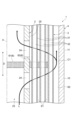
- 4 is a graph showing pressure loss measurement results in Comparative Example 1.
- FIG. 4 is a graph showing pressure loss measurement results of Example 1 and Comparative Example 1.
- FIG. 4 is a graph showing pressure loss measurement results of Example 1 and Comparative Example 1.
- FIG. 1 is a schematic cross-sectional view of the degassing module according to the embodiment.
- FIG. 2 is a schematic cross-sectional view along line II-II shown in FIG. 3 to 6 are schematic sectional views enlarging a part of the degassing module shown in FIG.
- the degassing module 1 according to the embodiment is a module for degassing the liquid L.
- the liquid L to be degassed by the degassing module 1 is not particularly limited. Examples include organic solvents such as alcohols and hydrocarbons, and ionic liquids.
- the degassing module 1 includes a pipe 2, a hollow fiber membrane group 3, a housing 4, a partition section 5, a baffle 6, and a support section 7.
- the pipe 2 is a cylindrical member extending linearly along the central axis A.
- the direction in which the pipe 2 extends cylindrically, that is, the direction of the central axis A is called an extension direction D.
- the pipe 2 forms an intra-pipe flow path 23 having a liquid supply port 21 and a liquid discharge port 22 .
- the pipe internal flow path 23 is a flow path formed by the inner peripheral surface of the pipe 2 and through which the liquid L can flow.
- a plurality of holes 24 are formed in the pipe 2 to open the pipe internal flow path 23 .
- the plurality of holes 24 are holes for discharging the liquid L from the in-pipe channel 23 to the outside of the pipe 2 and for letting the liquid L into the in-pipe channel 23 from the outside of the pipe 2 .
- the pipe 2 has a hole-formed portion 25 , a first hole-unformed portion 26 and a second hole-unformed portion 27 .
- the hole forming portion 25 is a portion in which a plurality of holes 24 are formed.
- the first non-hole-formed portion 26 and the second non-hole-formed portion 27 are portions where the plurality of holes 24 are not formed.
- the hole forming portion 25 is located in the central portion of the pipe 2 in the extending direction D.
- the first non-hole forming portion 26 is adjacent to the liquid supply port 21 side of the hole forming portion 25 in the extending direction D.
- the second hole non-formed portion 27 is adjacent to the hole formed portion 25 in the extension direction D on the liquid outlet 22 side.
- the inner and outer diameters of the hole-formed portion 25, the first hole-unformed portion 26, and the second hole-unformed portion 27 are not particularly limited.
- the inner and outer diameters of the hole-formed portion 25 may be larger than the inner and outer diameters of the first non-hole-formed portion 26 and the second non-hole-formed portion 27.
- the hole-formed portion 25, the first hole-unformed portion 26, and the second hole-unformed portion 27 are separate members, and the small-diameter first hole-unformed portion 26 is provided at both ends of the large-diameter hole-formed portion 25.
- the pipe 2 may be configured by inserting the second non-hole forming portion 27 .
- the hollow fiber membrane group 3 is arranged on the outer peripheral side of the pipe 2 so that a plurality of hollow fiber membranes 31 cover the plurality of holes 24 . That is, the hollow fiber membrane group 3 is composed of a plurality of hollow fiber membranes 31 arranged on the outer peripheral side of the pipe 2 so as to cover the plurality of holes 24 .
- Each of the plurality of hollow fiber membranes 31 is a hollow fiber membrane that allows the gas G to permeate but the liquid L not to permeate.
- the material, membrane shape, membrane form, and the like of each of the plurality of hollow fiber membranes 31 are not particularly limited.
- Examples of the material for each of the plurality of hollow fiber membranes 31 include polyolefin resins such as polypropylene, polyethylene, and polymethylpentene; silicone resins such as polydimethylsiloxane copolymers thereof; fluorine resins such as PTFE and vinylidene fluoride. resin.
- each of the plurality of hollow fiber membranes 31 examples include a porous film, a microporous film, and a homogeneous film having no porosity (non-porous film).
- Examples of the form of each of the plurality of hollow fiber membranes 31 include a symmetrical membrane (homogeneous membrane) in which the chemical or physical structure of the entire membrane is homogeneous, and an asymmetric membrane in which the chemical or physical structure of the membrane differs depending on the part of the membrane.
- membranes heterogeneous membranes
- Asymmetric membranes are membranes having non-porous dense layers and porous layers.
- the dense layer may be formed anywhere in the film, such as the surface layer of the film or the inside of the porous film.
- Heterogeneous films also include composite films with different chemical structures and multi-layer structures such as three-layer structures.
- a heterogeneous film using poly-4-methylpentene-1 resin is particularly preferable because it has a dense layer that blocks the liquid L.
- a dense layer is formed on the outer surface.
- the outer diameter of each of the plurality of hollow fiber membranes 31 is not particularly limited. From the viewpoint of increasing the membrane area, the outer diameter of each of the plurality of hollow fiber membranes 31 can be, for example, 500 ⁇ m or less, preferably 350 ⁇ m or less, more preferably 250 ⁇ m or less. On the other hand, from the viewpoint of suppressing breakage, the outer diameter of each of the plurality of hollow fiber membranes 31 can be, for example, 50 ⁇ m or more, preferably 150 ⁇ m or more, and more preferably 200 ⁇ m or more.
- the hollow fiber membrane group 3 is arranged on the outer peripheral side of the hole formed portion 25 of the pipe 2 and is not arranged on the outer peripheral side of the first non-hole formed portion 26 and the second non-hole formed portion 27 of the pipe 2 .
- the hollow fiber membrane group 3 is formed in a substantially cylindrical shape so as to surround the hole forming portion 25 .
- the hollow fiber membrane group 3 is formed of, for example, a blind-like hollow fiber membrane fabric 8 (see FIG. 8).
- the hollow fiber membrane fabric 8 is a fabric in which a plurality of hollow fiber membranes 31 serving as wefts and warp threads 9 are woven. In the hollow fiber membrane fabric 8, a plurality of hollow fiber membranes 31 are arranged in a reed pattern. The interval between the adjacent hollow fiber membranes 31 can be adjusted by, for example, the thickness of the warp yarns 9, the weaving method of the hollow fiber membrane fabric 8, and the like.
- an inter-membrane space S1 through which the liquid L can flow is formed between the plurality of hollow fiber membranes 31 (between the adjacent hollow fiber membranes 31).
- the inter-membrane space S1 is also formed between the plurality of hollow fiber membranes 31 in the circumferential direction of the pipe 2 and is also formed between the plurality of hollow fiber membranes 31 in the circumferential direction of the pipe 2 .
- the housing 4 is connected to the outer peripheral surface of the pipe 2 and accommodates the hollow fiber membrane group 3 .
- the housing 4 is formed in a cylindrical shape extending in the extending direction D of the pipe 2 . Both ends of the housing 4 in the extending direction D are airtightly connected to the outer peripheral surface of the pipe 2 .
- the connection of the housing 4 to the pipe 2 can be performed, for example, by welding, adhesion, or the like. Both ends of the pipe 2 do not need to protrude from the housing 4 , but in the present embodiment, the ends of the pipe 2 protrude from the housing 4 in order to facilitate connection of other members to the pipe 2 .
- An intake port 41 is formed in the housing 4 .
- the intake port 41 is an opening for sucking air from the housing 4 .
- the intake port 41 is composed of a first intake port 42 and a second intake port 43 .
- Each of the first intake port 42 and the second intake port 43 is an opening for sucking air from the housing 4 .
- a suction device (not shown) such as a vacuum pump is connected to the first intake port 42 and the second intake port 43, for example.
- a liquid circulation space S2 is formed in the housing 4 .
- the liquid flow space S2 is a space between the hollow fiber membrane group 3 and the housing 4 through which the liquid L can flow.
- the liquid circulation space S2 is a space formed between the hollow fiber membrane group 3 and the housing 4 at least when the degassing module 1 is not in use. Therefore, the hollow fiber membrane group 3 is not in contact with the inner peripheral surface of the housing 4 when the degassing module 1 is not in use. After the degassing module 1 is used, the hollow fiber membrane group 3 may come into contact with the inner peripheral surface of the housing 4 due to swelling of the plurality of hollow fiber membranes 31 .
- the partition part 5 partitions the area inside the housing 4 into an internal area R1 and an external area R2.
- the internal region R ⁇ b>1 is a region including the inner peripheral side spaces 32 of the plurality of hollow fiber membranes 31 .
- the outer region R2 is a region containing the inter-membrane space S1. Therefore, each of the plurality of hollow fiber membranes 31 serves as a boundary between the inner region R1 and the outer region R2.
- Each of the plurality of hollow fiber membranes 31 prevents passage of the liquid L from the outer region R2 to the inner region R1, and prevents gas G (dissolved gas in the liquid L, gas in the liquid L) from the outer region R2 to the inner region R1 air bubbles, etc.) to pass through.
- the partition section 5 has a first sealing section 51 and a second sealing section 52 .
- the first sealing portion 51 is arranged at the first end portion 33 on one side of the hollow fiber membrane group 3 in the extending direction D. As shown in FIG.
- the first end portion 33 is the end portion on the liquid supply port 21 side in the extending direction D.
- the first end portion 33 of the hollow fiber membrane group 3 is fixed to the outer peripheral surface of the pipe 2 and the inner peripheral surface of the housing 4 by the first sealing portion 51 .
- the second sealing portion 52 is arranged at the second end portion 34 on the other side of the hollow fiber membrane group 3 in the extending direction D. As shown in FIG.
- the second end portion 34 is the end portion on the side of the liquid outlet 22 in the extending direction D. As shown in FIG.
- the second end portion 34 of the hollow fiber membrane group 3 is fixed to the outer peripheral surface of the pipe 2 and the inner peripheral surface of the housing 4 by the second sealing portion 52 .
- the first sealing portion 51 and the second sealing portion 52 are made of resin, for example.
- resins used for the first sealing portion 51 and the second sealing portion 52 include epoxy resins, urethane resins, ultraviolet curing resins, and polyolefin resins such as polyethylene and polypropylene.
- Each of the first sealing portion 51 and the second sealing portion 52 fills the entire area between the pipe 2 and the housing 4 except for the plurality of hollow fiber membranes 31 in the orthogonal cross section orthogonal to the extending direction D. ing. That is, each of the first sealing portion 51 and the second sealing portion 52 is located between the pipe 2 and the hollow fiber membrane group 3, between the plurality of hollow fiber membranes 31, and between the hollow fiber membrane group 3 and the housing 4. is filled between The inner peripheral space 32 of each of the plurality of hollow fiber membranes 31 is open from the first sealing portion 51 to the liquid supply port 21 side, and is open from the second sealing portion 52 to the liquid discharge port 22 side. is open.
- the first sealing portion 51 is arranged between the hole forming portion 25 and the first hole non-forming portion 26 in the extending direction D.
- the second sealing portion 52 is arranged between the hole forming portion 25 and the second hole non-forming portion 27 in the extending direction D.
- the plurality of holes 24 of the pipe 2 are formed between the first sealing portion 51 and the second sealing portion 52 in the extending direction D.
- the area between the pipe 2 and the housing 4 on the side of the liquid supply port 21 of the first sealing portion 51 is an internal area R1.
- a region between the pipe 2 and the housing 4 on the liquid outlet 22 side of the second sealing portion 52 is an internal region R1.
- the first intake port 42 is arranged on the side opposite to the second sealing portion 52 of the first sealing portion 51 in the extending direction D, that is, on the liquid supply port 21 side of the first sealing portion 51 in the extending direction D. It is The first intake port 42 is connected to an internal region R1 located between the pipe 2 and the housing 4 and on the liquid supply port 21 side of the first sealing portion 51 .
- the second intake port 43 is arranged on the side of the second sealing portion 52 opposite to the first sealing portion 51 in the extending direction D, that is, on the liquid outlet 22 side of the second sealing portion 52 in the extending direction D. It is The second intake port 43 communicates with an internal region R1 located between the pipe 2 and the housing 4 on the side of the liquid discharge port 22 of the second sealing portion 52 .
- the baffle 6 separates the first sealing portion 51 and the second sealing portion 52 in the extending direction D in order to detour the liquid L supplied to the liquid supply port 21 and bring it into contact with the plurality of hollow fiber membranes 31 . placed in between.
- the region of the degassing module 1 between the first sealing portion 51 and the baffle 6 in the extending direction D is called an upstream portion 10
- the region between the baffle 6 and the second sealing portion 52 in the extending direction D is called an upstream portion 10.
- the region of the degassing module 1 in between is called the downstream portion 11 .
- the baffle 6 partitions the pipe inner channel 23 and the inter-membrane space S1 in the extending direction D. That is, the pipe internal flow path 23 is partitioned in the extending direction D by the baffle 6 . In addition, the inter-membrane space S1 is partitioned in the extending direction D by the baffle 6 . Therefore, the liquid L supplied from the liquid supply port 21 to the in-pipe flow path 23 exits the pipe 2 in the upstream section 10, passes through the inter-membrane space S1, and passes through the baffle clearance C1 between the baffle 6 and the housing 4. and enters the pipe 2 at the downstream portion 11 through the intermembrane space S1.
- the position of the baffle 6 in the extending direction D can be any position between the first sealing portion 51 and the second sealing portion 52 .
- the baffle 6 divides the space between the first sealing portion 51 and the second sealing portion 52 into three in the extending direction D. can be placed in the center of the
- the baffle 6 has an inner baffle 61 and an outer baffle 62.
- the inner baffle 61 is arranged on the inner peripheral side of the pipe 2 and partitions the pipe inner flow path 23 in the extending direction D.
- the outer baffle 62 is arranged on the outer peripheral side of the pipe 2 and partitions at least part of the inter-membrane space S1 in the extending direction D.
- the inner baffle 61 may completely partition the pipe inner channel 23 in the extending direction D, or may imperfectly partition the pipe inner channel 23 in the extending direction D. That is, even if the inner baffle 61 completely blocks the pipe channel 23 so that the liquid L cannot pass from the pipe channel 23 of the upstream portion 10 to the pipe channel 23 of the downstream portion 11, good. In addition, the inner baffle 61 partially blocks the pipe internal flow path 23 so that the liquid L can pass from the pipe internal flow path 23 of the upstream section 10 to the pipe internal flow path 23 of the downstream section 11. good. Even if the inner baffle 61 partially closes the pipe channel 23 , the inner baffle 61 prevents the passage of the liquid L from the pipe channel 23 in the upstream portion 10 to the pipe channel 23 in the downstream portion 11 . Since it is partially blocked, the liquid L supplied to the liquid supply port 21 can be detoured and brought into contact with the plurality of hollow fiber membranes 31 .
- the inner baffle 61 is made of resin, for example.
- the resin used for the inner baffle 61 include urethane-based resins such as polyurethane (PU) and thermoplastic polyurethane (TPU); polycarbonate (PC); polyvinyl chloride (PVC); Vinyl chloride resin; acrylic resin such as polyacrylic acid, polymethacrylic acid, polymethyl acrylate, polymethyl methacrylate (PMMA), polyethyl methacrylate; polyethylene terephthalate (PET), polybutylene terephthalate Polytrimethylene terephthalate, polyethylene naphthalate, polyester resins such as polybutylene naphthalate; polyamide resins such as nylon (registered trademark); polystyrene (PS), imide-modified polystyrene, acrylonitrile Polystyrene resins such as butadiene-styrene (ABS) resin, imide-modified ABS resin, styrene-acrylonit
- the outer baffle 62 may completely partition the inter-membrane space S1 in the extending direction D, or may imperfectly partition the inter-membrane space S1 in the extending direction D. That is, the outer baffle 62 may completely block the inter-membrane space S1 so that the liquid L cannot pass from the inter-membrane space S1 of the upstream portion 10 to the inter-membrane space S1 of the downstream portion 11 . Further, the outer baffle 62 may partially block the inter-membrane space S1 so as to allow passage of the liquid L from the inter-membrane space S1 of the upstream portion 10 to the inter-membrane space S1 of the downstream portion 11 .
- the outer baffle 62 is separated from the housing 4. However, the outer baffle 62 may be in contact with the housing 4 as long as the baffle clearance C1 is formed even partially between the outer baffle 62 and the housing 4 . Further, the outer baffle 62 is not arranged in the liquid circulation space S2, but is arranged in the liquid circulation space S2 if the baffle clearance C1 is formed even partially between the outer baffle 62 and the housing 4. may
- the outer baffle 62 is made of resin, for example.
- the resin used for the outer baffle 62 include urethane-based resins such as polyurethane (PU) and thermoplastic polyurethane (TPU); polycarbonate (PC); polyvinyl chloride (PVC); Vinyl chloride resin; acrylic resin such as polyacrylic acid, polymethacrylic acid, polymethyl acrylate, polymethyl methacrylate (PMMA), polyethyl methacrylate; polyethylene terephthalate (PET), polybutylene terephthalate Polytrimethylene terephthalate, polyethylene naphthalate, polyester resins such as polybutylene naphthalate; polyamide resins such as nylon (registered trademark); polystyrene (PS), imide-modified polystyrene, acrylonitrile Polystyrene resins such as butadiene-styrene (ABS) resin, imide-modified ABS resin, styrene-acrylonit
- the support part 7 is arranged on the liquid outlet 22 side of the baffle 6 in the extension direction D and supports at least part of the plurality of hollow fiber membranes 31 with respect to the pipe 2 .
- the plurality of hollow fiber membranes 31 are pressed toward the pipe 2 by the flow of the liquid L entering the pipe 2, and the hollow fiber membranes 31 on the outer peripheral side slip between the hollow fiber membranes 31 on the inner peripheral side. Equally, the inter-membrane space S1 serving as the flow path for the liquid L is narrowed.
- each of the plurality of hollow fiber membranes 31 is a heterogeneous membrane having a dense layer, or has an outer diameter of 500 ⁇ m or less, 350 ⁇ m or less, or 250 ⁇ m or less, this tendency becomes stronger. Therefore, the support portion 7 supports at least a portion of the plurality of hollow fiber membranes 31 with respect to the pipe 2 so as to resist the flow of the liquid L entering the pipe 2 in the downstream portion 11 .
- the support portion 7 may support all of the plurality of hollow fiber membranes 31 with respect to the pipe 2 , or may support only a portion of the plurality of hollow fiber membranes 31 with respect to the pipe 2 . In the present embodiment, the support portion 7 supports all of the plurality of hollow fiber membranes 31 with respect to the pipe 2 from the viewpoint of further suppressing narrowing of the inter-membrane space S1.
- the support portion 7 may have any shape, structure, etc. as long as it can support at least a portion of the plurality of hollow fiber membranes 31 .
- the support portion 7 is directly or indirectly connected to at least a portion of the plurality of hollow fiber membranes 31 and the pipe 2 . That the support portion 7 is indirectly connected to at least a portion of the plurality of hollow fiber membranes 31 and the pipe 2 is, for example, between the support portion 7 and at least a portion of the plurality of hollow fiber membranes 31 and the pipe 2 In some cases, other members may be arranged.
- the support portion 7 may be filled in the entire area between the pipe 2 and the hollow fiber membrane group 3 and the entire area of the inter-membrane space S1.
- the support portion 7 may be filled only in the pipe 2, a part of the hollow fiber membrane group 3, and a part of the inter-membrane space S1.
- the support part 7 is separated from the housing 4 and a support part clearance C2 is formed between the support part 7 and the housing 4 .
- a support part clearance C2 is formed between the support part 7 and the housing 4 .
- the support portion 7 and the The support portion 7 may be in contact with the housing 4 as long as the support portion clearance C ⁇ b>2 is formed even partially between the support portion 7 and the housing 4 .
- the support portion 7 is spaced apart from the housing 4 in order to reduce the pressure loss of the liquid L and lengthen the contact time between the plurality of hollow fiber membranes 31 and the liquid L.
- the support part 7 is not arranged in the liquid circulation space S2. However, if the movement of the liquid L from the liquid supply port 21 side (the baffle 6 side) to the liquid discharge port 22 side (the second hole non-forming portion 27 side) with respect to the support portion 7 is not prevented, or the support portion 7 and the The support portion 7 may be arranged in the liquid circulation space S2 as long as the support portion clearance C2 is formed even partially between the support portion 7 and the housing 4 . In this embodiment, from the viewpoint of reducing the pressure loss of the liquid L and increasing the contact time between the plurality of hollow fiber membranes 31 and the liquid L, the support section 7 is not arranged in the liquid circulation space S2.
- the plurality of holes 24 of the pipe 2 are located on the liquid supply port 21 side (baffle 6 side) of the support section 7 in the extension direction D and on the liquid discharge port 22 side of the support section 7 in the extension direction D (second hole non-formation side). 27 side) and may be formed on only one side.
- the plurality of holes 24 of the pipe 2 are located on the side of the liquid supply port 21 of the support section 7 in the extending direction D (baffle 6 side) and in the extending direction D. It is formed both on the liquid discharge port 22 side (the second non-hole forming portion 27 side) of the support portion 7 at D.
- the position of the support portion 7 in the extending direction D can be any position between the baffle 6 and the second non-hole forming portion 27 .
- the support portion 7 is arranged in the central portion when the space between the baffle 6 and the second non-hole-formed portion 27 is divided into three in the extending direction D. can do.
- the support portion 7 is made of resin, for example.
- the resin used for the support portion 7 include urethane-based resins such as polyurethane (PU) and thermoplastic polyurethane (TPU); polycarbonate (PC); polyvinyl chloride (PVC); Vinyl chloride resin; acrylic resin such as polyacrylic acid, polymethacrylic acid, polymethyl acrylate, polymethyl methacrylate (PMMA), polyethyl methacrylate; polyethylene terephthalate (PET), polybutylene terephthalate Polytrimethylene terephthalate, polyethylene naphthalate, polyester resins such as polybutylene naphthalate; polyamide resins such as nylon (registered trademark); polystyrene (PS), imide-modified polystyrene, acrylonitrile Polystyrene resins such as butadiene-styrene (ABS) resin, imide-modified ABS resin, styrene-acrylonitrile copoly
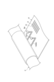
- FIG. 7 and 8 are schematic cross-sectional views explaining an example of a method of forming the baffle 6 and the support portion 7.
- FIG. 7 When forming the baffle 6 and the support portion 7, first, as shown in FIG. This disk-shaped member becomes the inner baffle 61 .
- the hollow fiber membrane fabric 8 is wound around the pipe 2 so as to cover the plurality of holes 24 of the pipe 2 .
- the hollow fiber membrane fabric 8 is, as described above, a fabric in which a plurality of hollow fiber membranes 31 serving as wefts are woven with the warp 9 .
- the first molten resin 13 is applied to a position corresponding to the outer baffle 62 of the inner surface 8a of the fabric.
- a second molten resin 14 is applied to a position corresponding to the support portion 7 on the surface 8a.
- the hollow fiber membrane fabric 8 coated with the first molten resin 13 and the second molten resin 14 is wound around the pipe 2 .
- the first molten resin 13 and the second molten resin 14 impregnate the hollow fiber membrane fabric 8 on the inner layer side and the hollow fiber membrane fabric 8 on the outer layer side, and fill the positions corresponding to the outer baffle 62 and the support section 7. state.
- the first molten resin 13 and the second molten resin 14 are cured, so that the first molten resin 13 becomes the outer baffle 62 and the second molten resin 14 becomes the support portion 7 .
- the internal region R1 is sucked from the first intake port 42 and the second intake port 43, and the liquid L is supplied from the liquid supply port 21 to the pipe internal channel 23.
- Intake of the internal region R1 from the first intake port 42 and the second intake port 43 is performed by connecting a suction device (not shown) such as a vacuum pump to the first intake port 42 and the second intake port 43, for example. It can be done by activating the device.
- a suction device such as a vacuum pump
- the liquid supplied to the pipe internal flow path 23 passes through the plurality of holes 24 formed in the pipe 2 in the upstream section 10 so as to bypass the baffle 6, exits the pipe 2, and enters the inter-membrane space S1. pass through
- gas G such as dissolved gas in the liquid L and air bubbles contained in the liquid L is released into the plurality of hollow fiber membranes. 31, whereby the liquid L is degassed.
- the liquid L passes through the baffle clearance C 1 , passes through the inter-membrane space S 1 in the downstream portion 11 , and enters the pipe 2 through a plurality of holes 24 formed in the pipe 2 .
- each of the plurality of hollow fiber membranes 31 since the inner peripheral space 32 of each of the plurality of hollow fiber membranes 31 is in a decompressed state, the dissolved gas in the liquid L and the gas G such as air bubbles contained in the liquid L are released into the plurality of hollow fibers. Each of the membranes 31 is passed through, whereby the liquid L is degassed. After that, the deaerated liquid L entering the pipe 2 is discharged from the liquid discharge port 22 .
- the internal region R1 is sucked from the first intake port 42 and the second intake port 43, and the liquid L is supplied from the liquid supply port 21 to the pipe channel 23.
- the liquid L can be degassed.
- the pipe internal flow path 23 and the inter-membrane space S1 are partitioned in the extending direction D by the baffle 6 . Therefore, when the liquid L is supplied from the liquid supply port 21 to the pipe internal channel 23, the liquid L exits the pipe 2 on the liquid supply port 21 side of the baffle 6, passes through the inter-membrane space S1, and flows through the baffle 6 and the housing.
- the plurality of hollow fiber membranes 31 are pressed toward the pipe 2 by the flow of the liquid L that crosses the baffle 6 and enters the pipe 2 again.
- a support portion 7 that supports at least a portion of the plurality of hollow fiber membranes 31 with respect to the pipe 2 is arranged on the liquid outlet 22 side of the baffle 6 , which is the downstream side of the baffle 6 . Therefore, due to the flow of the liquid L that crosses the baffle 6 and enters the pipe 2 again, the hollow fiber membranes 31 on the outer peripheral side slip between the hollow fiber membranes 31 on the inner peripheral side, thereby forming a flow path for the liquid L. Narrowing of the interspace S1 is suppressed. Thereby, the pressure loss of the liquid L can be reduced as compared with the case where the support portion 7 is not arranged.
- this degassing module 1 since the support portion 7 is separated from the housing 4 , the liquid L that has passed over the baffle 6 can flow along the inner peripheral surface of the housing 4 until it passes over the support portion 7 . . As a result, it is possible to widen the area where the plurality of hollow fiber membranes 31 and the liquid L are in contact with each other on the side of the liquid discharge port 22 of the support section 7 which is the downstream side of the support section 7 .
- the baffle 6 is separated from the housing 4, so the pressure loss of the liquid L when the liquid L passes through the baffle clearance C1 between the baffle 6 and the housing 4 can be reduced. can be done.
- the baffle 6 partitions the entire inter-membrane space S1 in the extending direction D, so that the liquid coming out of the pipe 2 is located on the liquid supply port 21 side of the baffle 6, which is the upstream side of the baffle 6. L can flow to the outside of the hollow fiber membrane group 3 .
- the contact time between the plurality of hollow fiber membranes 31 and the liquid L can be lengthened, and the deaeration efficiency of the liquid L can be improved.
- the liquid circulation space S2 is formed between the hollow fiber membrane group 3 and the housing 4, the liquid L coming out of the pipe 2 passes through the inter-membrane space S1. It can enter the space S2 and then enter the pipe 2 from the liquid flow space S2 through the inter-membrane space S1. Therefore, the pressure loss of the liquid L can be reduced while the liquid L is brought into contact with the plurality of hollow fiber membranes 31 .
- the degassing module 1 since the support portion 7 is not arranged in the liquid circulation space S2, compared to the case where the support portion 7 is arranged in the liquid circulation space S2, the amount of the liquid L passing through the liquid circulation space S2 is reduced. pressure loss can be reduced.
- the baffle 6 has an inner baffle 61 arranged on the inner peripheral side of the pipe 2 and an outer baffle 62 arranged on the outer peripheral side of the pipe 2, so that the pipe 2 extends in the extending direction D.
- the baffle 6 can be arranged without dividing into two.
- each of the first sealing portion 51 and the second sealing portion 52 has a plurality of hollow fiber membranes between the pipe 2 and the housing 4 in an orthogonal cross section orthogonal to the extending direction D.
- the entire area except 31 is filled, and a plurality of holes 24 of the pipe 2 are formed between the first sealing portion 51 and the second sealing portion 52 . Therefore, the first sealing portion 51 and the second sealing portion 52 can partition the area inside the housing 4 into the internal area R1 and the external area R2.
- the extending direction D The liquid L can be brought into contact with the plurality of hollow fiber membranes 31 over a long range.
- the first inlet 42 and the second inlet 43 are formed outside the first sealing section 51 and the second sealing section 52 in the extending direction D. Air can be sucked into the inner peripheral side spaces 32 of the plurality of hollow fiber membranes 31 from both ends of the hollow fiber membranes 31 . Thereby, the degassing efficiency of the liquid L can be improved.
- the pressure loss of the liquid L can be reduced.
- the present invention is not limited to the above embodiments.
- the pipe and the housing are separate members, but the pipe and the housing may be integrated as long as there is no manufacturing problem.
- Example 1 As Experiment 1, the pressure loss of the liquid was measured using the degassing module of Comparative Example 1 that did not include the supporting portion.
- the degassing module of Comparative Example 1 was the same as the degassing module 1 according to the embodiment, except that it did not have a support.
- the flow rate of the liquid supplied to the degassing module was changed, and the pressure loss of the liquid was measured at three points: the upstream section, the baffle clearance between the baffle and the housing, and the downstream section.
- the measurement results are shown in FIG. 9 is a graph showing the measurement results of pressure loss in Comparative Example 1.
- FIG. 9 is a graph showing the measurement results of pressure loss in Comparative Example 1.
- the liquid pressure loss was much larger in the upstream and downstream parts compared to the baffle clearance between the baffle and the housing. Moreover, the pressure loss of the liquid was significantly larger in the downstream portion than in the upstream portion. From these results, in the downstream part, the hollow fiber membranes on the outer peripheral side are pushed between the hollow fiber membranes on the inner peripheral side by pressing the plurality of hollow fiber membranes toward the pipe side in the flow of liquid entering the pipe. It is thought that the inter-membrane space narrowed, and as a result, the pressure loss of the liquid increased.
- Example 2 As Experiment 2, the degassing module of Comparative Example 1 and the degassing module of Example 1 were used to measure the pressure loss of the liquid.
- the degassing module of Example 1 was the same as the degassing module 1 according to the embodiment described above.
- the flow rate of the liquid supplied to the degassing module was changed, and the pressure loss of the liquid from the liquid supply port to the liquid discharge port of the degassing module was measured.
- FIG. 10 shows the measurement results.
- FIG. 10 is a graph showing measurement results of pressure loss in Example 1 and Comparative Example 1.
- the pressure loss of the liquid in the degassing module of Example 1 provided with the support portion was significantly smaller than that in the degassing module of Comparative Example 1 not provided with the support portion.
- the pressure loss of the liquid in the degassing module of Example 1 is greater than the pressure loss of the liquid in the degassing module of Comparative Example 1. decreased by more than 60%. From these results, it is considered that the pressure loss of the liquid can be reduced by providing the support portion.
Abstract
The present invention reduces the pressure loss of a liquid. More specifically, this degassing module 1 comprises: a pipe 2 that forms a pipe inner flow path 23 having a liquid supply port 21 and a liquid discharge port 22, and has a plurality of holes 24 formed therein; a hollow fiber membrane group 3 in which a plurality of hollow fiber membranes 31 are disposed on the outer circumferential side of the pipe 2 so as to cover the plurality of holes 24; a housing 4 that stores the hollow fiber membrane group 3; a partition part 5 that partitions the region inside the housing 4 into an inner region R1 including the inner circumferential–side space 32 of each of the plurality of hollow fiber membranes 31, and an outer region R2 including inter-membrane spaces S1 between the plurality of hollow fiber membranes 31; an intake port 41 of the housing 4 that communicates with the inner region R1; a baffle 6 that partitions the pipe inner flow path 23 of the pipe 2 and the inter-membrane spaces S1 in the extension direction D of the pipe 2; and a support part 7 that is disposed on the liquid discharge port 22 side of the baffle 6 and supports at least a portion of the plurality of hollow fiber membranes 31 with respect to the pipe 2.
Description
本発明は、液体を脱気する脱気モジュール及び液体の脱気方法に関する。
The present invention relates to a degassing module for degassing a liquid and a liquid degassing method.
従来から、複数の中空糸膜を用いて液体を脱気する脱気モジュールが知られている。このような脱気モジュールとして、例えば、特許文献1に記載された接触器がある。特許文献1に記載された接触器は、穴の開いたパイプと、パイプを取り囲む複数の中空糸膜と、液体の流れを方向転換するバッフルと、複数の中空糸膜の端部をパイプに固定する管シートと、複数の中空糸膜を収容する殻と、殻に形成された吸気口と、を備える。この接触器では、パイプに液体が供給されると、液体は、バッフルの上流側においてパイプから出て、複数の中空糸膜の間の膜間空間を通り、バッフルと殻との間を通り、その後、複数の中空糸膜の間の膜間空間を通り、バッフルの下流側において再びパイプに入る。このとき、吸気口から中空糸膜の内腔が真空吸引されることで、液体の同伴ガスが中空糸膜の内腔側に移動し、液体が脱気される。そして、脱気された液体は、パイプから排出される。
A deaeration module that deaerates a liquid using multiple hollow fiber membranes has been known for some time. As such a degassing module, for example, there is a contactor described in Patent Document 1. The contactor described in Patent Document 1 includes a perforated pipe, a plurality of hollow fiber membranes surrounding the pipe, a baffle for changing the direction of the liquid flow, and a plurality of hollow fiber membrane ends fixed to the pipe. a tube sheet that holds a plurality of hollow fiber membranes; a shell that accommodates a plurality of hollow fiber membranes; and an air inlet formed in the shell. In this contactor, when the pipe is supplied with liquid, the liquid exits the pipe upstream of the baffle, passes through the intermembrane space between the plurality of hollow fiber membranes, passes between the baffle and the shell, It then passes through the intermembrane space between the hollow fiber membranes and re-enters the pipe downstream of the baffle. At this time, the lumen of the hollow fiber membrane is vacuum-sucked from the intake port, so that gas accompanying the liquid moves to the lumen side of the hollow fiber membrane, and the liquid is degassed. The degassed liquid is then discharged through the pipe.
特許文献1に記載された接触器のように、脱気モジュールにバッフルを設けることで、脱気モジュールの脱気性能を向上することができる。特に、大型の脱気モジュールにおいては、その効果が大きい。
By providing a baffle in the deaeration module like the contactor described in Patent Document 1, the deaeration performance of the deaeration module can be improved. In particular, the effect is great in a large-sized degassing module.
しかしながら、特許文献1に記載された接触器では、バッフルの下流側の複数の中空糸膜は、バッフルを越えて再びパイプに入る液体の流れによりパイプ側に押圧される。その結果、外周側の中空糸膜が内周側の中空糸膜の間に潜り込む等して液体の流路となる複数の中空糸膜の間の膜間空間が狭くなり、液体の圧力損失が高くなるという問題がある。
However, in the contactor described in Patent Document 1, the plurality of hollow fiber membranes on the downstream side of the baffle are pushed toward the pipe by the flow of liquid that crosses the baffle and enters the pipe again. As a result, the hollow fiber membranes on the outer peripheral side slip between the hollow fiber membranes on the inner peripheral side, etc., and the intermembrane space between the multiple hollow fiber membranes, which serves as a flow path for the liquid, becomes narrower, and the pressure loss of the liquid increases. There is the problem of getting taller.
そこで、本発明は、液体の圧力損失を低減することができる脱気モジュール及び液体の脱気方法を提供することを課題とする。
Therefore, an object of the present invention is to provide a degassing module and a liquid degassing method that can reduce the pressure loss of the liquid.
本発明の脱気モジュールは、液体供給口及び液体排出口を有するパイプ内流路を形成するとともにパイプ内流路を開放する複数の穴が形成されたパイプと、複数の中空糸膜が複数の穴を覆うようにパイプの外周側に配置されてなる中空糸膜群と、パイプの外周面に接続されて中空糸膜群を収容するハウジングと、ハウジング内の領域を、複数の中空糸膜のそれぞれの内周側空間を含む内部領域と、複数の中空糸膜の間の膜間空間を含む外部領域と、に仕切る仕切部と、内部領域に連通されたハウジングの吸気口と、パイプ内流路及び膜間空間をパイプの延在方向に仕切るバッフルと、延在方向におけるバッフルの液体排出口側に配置されて、パイプに対して複数の中空糸膜の少なくとも一部を支持する支持部と、を備える。
The degassing module of the present invention comprises a pipe having a plurality of holes for opening the pipe interior channel and having a liquid supply port and a liquid outlet port, and a plurality of hollow fiber membranes. A hollow fiber membrane group arranged on the outer peripheral side of the pipe so as to cover the hole, a housing connected to the outer peripheral surface of the pipe and containing the hollow fiber membrane group, and a region in the housing composed of a plurality of hollow fiber membranes. A partition that divides an internal region containing each inner peripheral space and an external region containing an inter-membrane space between a plurality of hollow fiber membranes, an intake port of the housing that communicates with the internal region, and a pipe inner flow a baffle that partitions the path and the inter-membrane space in the extending direction of the pipe; and a support that is arranged on the liquid outlet side of the baffle in the extending direction and supports at least a part of the plurality of hollow fiber membranes with respect to the pipe. , provided.
この脱気モジュールでは、吸気口から内部領域を吸気するとともに液体供給口からパイプ内流路に液体を供給することで、液体を脱気することができる。そして、パイプ内流路及び膜間空間がバッフルにより延在方向に仕切られている。このため、液体供給口からパイプ内流路に液体を供給すると、液体は、バッフルの液体供給口側においてパイプから出て、膜間空間を通り、バッフルとハウジングとの間のバッフルクリアランスを通り、膜間空間を通り、バッフルの液体排出口側において再びパイプに入る。このように、バッフルにより液体の流れを複雑にすることで、バッフルを備えない場合に比べて、脱気性能を向上することができる。
In this degassing module, the liquid can be degassed by sucking the internal area through the intake port and supplying the liquid to the pipe channel through the liquid supply port. The pipe internal flow path and the inter-membrane space are partitioned in the extending direction by baffles. Therefore, when liquid is supplied from the liquid supply port to the pipe channel, the liquid exits the pipe on the liquid supply port side of the baffle, passes through the inter-membrane space, passes through the baffle clearance between the baffle and the housing, It passes through the intermembrane space and re-enters the pipe on the liquid outlet side of the baffle. By complicating the flow of the liquid with the baffles in this way, the degassing performance can be improved compared to the case where no baffles are provided.
ここで、バッフルの液体排出口側では、複数の中空糸膜は、バッフルを越えて再びパイプに入る液体の流れによりパイプ側に押圧される。しかしながら、バッフルの下流側であるバッフルの液体排出口側に、パイプに対して複数の中空糸膜の少なくとも一部を支持する支持部が配置されている。このため、バッフルを越えて再びパイプに入る液体の流れによって、外周側の中空糸膜が内周側の中空糸膜の間に潜り込む等して液体の流路となる膜間空間が狭くなるのが抑制される。その結果、支持部が配置されない場合に比べて、液体の圧力損失を低減することができる。
Here, on the liquid outlet side of the baffle, the plurality of hollow fiber membranes are pressed toward the pipe side by the liquid flow that crosses the baffle and enters the pipe again. However, on the liquid outlet side of the baffle, which is the downstream side of the baffle, a support section is arranged to support at least part of the plurality of hollow fiber membranes with respect to the pipe. Therefore, due to the flow of liquid that crosses over the baffle and re-enters the pipe, the hollow fiber membranes on the outer peripheral side slip between the hollow fiber membranes on the inner peripheral side, and the inter-membrane space that serves as a flow path for the liquid narrows. is suppressed. As a result, the pressure loss of the liquid can be reduced as compared with the case where the support section is not arranged.
支持部は、パイプに対して複数の中空糸膜の全てを支持してもよい。この脱気モジュールでは、支持部がパイプに対して複数の中空糸膜の全てを支持するため、バッフルを越えて再びパイプに入る液体の流れによって、液体の流路となる膜間空間が狭くなるのを、更に抑制することができる。
The support part may support all of the plurality of hollow fiber membranes with respect to the pipe. In this degassing module, the supporting part supports all of the plurality of hollow fiber membranes against the pipe, so the flow of liquid that crosses the baffle and re-enters the pipe narrows the inter-membrane space that serves as the liquid flow path. can be further suppressed.
支持部は、ハウジングから離間していてもよい。この脱気モジュールでは、支持部がハウジングから離間しているため、バッフルを越えた液体は、支持部を越えるまでハウジングの内周面に沿って流れることができる。これにより、支持部の下流側である支持部の液体排出口側において、複数の中空糸膜と液体とが接触する領域を広げることができる。
The support part may be separated from the housing. In this degassing module, the support is spaced from the housing so that liquid that has passed over the baffle can flow along the inner peripheral surface of the housing until it passes over the support. As a result, it is possible to widen the region where the plurality of hollow fiber membranes and the liquid come into contact with each other on the liquid outlet side of the support section, which is the downstream side of the support section.
バッフルは、ハウジングから離間していてもよい。この脱気モジュールでは、バッフルがハウジングから離間しているため、液体がバッフルとハウジングとの間のバッフルクリアランスを通る際の、液体の圧力損失を低減することができる。
The baffle may be separated from the housing. In this degassing module, since the baffle is spaced from the housing, it is possible to reduce the pressure loss of the liquid when the liquid passes through the baffle clearance between the baffle and the housing.
バッフルは、膜間空間の全てを延在方向に仕切ってもよい。この脱気モジュールでは、バッフルが膜間空間の全てを延在方向に仕切るため、バッフルの上流側であるバッフルの液体供給口側において、パイプから出た液体を中空糸膜群の外側まで流すことができる。これにより、複数の中空糸膜と液体との接触時間を長くすることができるため、液体の脱気効率を向上することができる。
The baffle may partition the entire inter-membrane space in the extending direction. In this degassing module, the baffle partitions the entire intermembrane space in the extending direction, so that the liquid coming out of the pipe flows to the outside of the hollow fiber membrane group on the liquid supply port side of the baffle, which is the upstream side of the baffle. can be done. As a result, the contact time between the plurality of hollow fiber membranes and the liquid can be lengthened, so that the degassing efficiency of the liquid can be improved.
中空糸膜群とハウジングとの間に、液体が流通可能な液体流通空間が形成されていてもよい。この脱気モジュールでは、中空糸膜群とハウジングとの間に液体流通空間が形成されているため、パイプから出た液体は、膜間空間を通って液体流通空間に入り、その後、液体流通空間から膜間空間を通ってパイプに入ることができる。このため、液体を複数の中空糸膜に接触させつつ、液体Lの圧力損失を低減することができる。
A liquid circulation space through which liquid can flow may be formed between the hollow fiber membrane group and the housing. In this degassing module, since the liquid circulation space is formed between the hollow fiber membrane group and the housing, the liquid coming out of the pipe enters the liquid circulation space through the inter-membrane space, and then enters the liquid circulation space. can enter the pipe through the intermembrane space from Therefore, the pressure loss of the liquid L can be reduced while the liquid is brought into contact with the plurality of hollow fiber membranes.
支持部は、液体流通空間に配置されていなくてもよい。この脱気モジュールでは、支持部が液体流通空間に配置されていないため、支持部が液体流通空間に配置されている場合に比べて、液体流通空間を通る液体の圧力損失を低減することができる。
The support part does not have to be arranged in the liquid circulation space. In this degassing module, since the support is not arranged in the liquid circulation space, the pressure loss of the liquid passing through the liquid circulation space can be reduced compared to the case where the support is arranged in the liquid circulation space. .
バッフルは、パイプの内周側に配置されてパイプ内流路を延在方向に仕切る内側バッフルと、パイプの外周側に配置されて膜間空間を延在方向に仕切る外側バッフルと、を有してもよい。この脱気モジュールでは、バッフルがパイプの内周側に配置される内側バッフルとパイプの外周側に配置される外側バッフルとを有するため、パイプを延在方向に分割することなくバッフルを配置することができる。
The baffles include an inner baffle that is arranged on the inner peripheral side of the pipe and partitions the pipe internal flow path in the extending direction, and an outer baffle that is arranged on the outer peripheral side of the pipe and partitions the inter-membrane space in the extending direction. may In this degassing module, since the baffle has an inner baffle arranged on the inner peripheral side of the pipe and an outer baffle arranged on the outer peripheral side of the pipe, the baffle can be arranged without dividing the pipe in the extending direction. can be done.
仕切部は、延在方向における中空糸膜群の一方側の第一端部に配置される第一封止部と、延在方向における中空糸膜群の他方側の第二端部に配置される第二封止部と、を有し、第一封止部及び第二封止部のそれぞれは、延在方向と直交する直交断面において、パイプとハウジングとの間の、複数の中空糸膜を除く全域に充填されており、パイプの複数の穴は、延在方向における第一封止部と第二封止部との間に形成されていてもよい。この脱気モジュールでは、第一封止部及び第二封止部のそれぞれが、延在方向と直交する直交断面においてパイプとハウジングとの間の複数の中空糸膜を除く全域に充填されており、パイプの複数の穴が第一封止部と第二封止部との間に形成されている。このため、第一封止部及び第二封止部により、ハウジング内の領域を内部領域と外部領域とに仕切ることができる。そして、第一封止部及び第二封止部が、延在方向における中空糸膜群の一方側の第一端部及び他方側の第二端部に配置されているため、延在方向に長い範囲で、液体を複数の中空糸膜に接触させることができる。
The partition part is arranged at a first end on one side of the group of hollow fiber membranes in the extending direction, and a second end on the other side of the group of hollow fiber membranes in the extending direction. and a second sealing portion, wherein each of the first sealing portion and the second sealing portion has a plurality of hollow fiber membranes between the pipe and the housing in an orthogonal cross section orthogonal to the extending direction and the plurality of holes of the pipe may be formed between the first sealing portion and the second sealing portion in the extending direction. In this degassing module, each of the first sealing part and the second sealing part is filled in the entire area except for the plurality of hollow fiber membranes between the pipe and the housing in the orthogonal cross section orthogonal to the extending direction. , a plurality of holes in the pipe are formed between the first sealing part and the second sealing part. Therefore, the area inside the housing can be partitioned into an internal area and an external area by the first sealing portion and the second sealing portion. Further, since the first sealing portion and the second sealing portion are arranged at the first end portion on one side and the second end portion on the other side of the hollow fiber membrane group in the extending direction, Over a long range, the liquid can contact multiple hollow fiber membranes.
吸気口は、延在方向における第一封止部の第二封止部とは反対側に形成された第一吸気口と、延在方向における第二封止部の第一封止部とは反対側に形成された第二吸気口と、を有してもよい。この脱気モジュールでは、延在方向における第一封止部及び第二封止部の外側に第一吸気口及び第二吸気口が形成されているため、複数の中空糸膜の両端から複数の中空糸膜のそれぞれの内周側空間を吸気することができる。これにより、液体の脱気効率を向上することができる。
The air inlet is composed of a first air inlet formed on the side opposite to the second sealing portion of the first sealing portion in the extending direction, and a first sealing portion of the second sealing portion in the extending direction. and a second inlet formed on the opposite side. In this degassing module, since the first inlet and the second inlet are formed outside the first sealing part and the second sealing part in the extending direction, the plurality of hollow fiber membranes from both ends of the plurality of hollow fiber membranes Each inner peripheral space of the hollow fiber membrane can be sucked. As a result, it is possible to improve the degassing efficiency of the liquid.
本発明に係る液体の脱気方法は、上述した何れかの脱気モジュールにおいて、吸気口から内部領域を吸気するとともに、液体供給口からパイプ内流路に液体を供給する。この液体の脱気方法では、上述した何れかの脱気モジュールを用いて液体を脱気するため、液体の圧力損失を低減することができる。
A method for degassing a liquid according to the present invention, in any one of the degassing modules described above, sucks the internal region from the intake port and supplies the liquid from the liquid supply port to the pipe channel. In this liquid degassing method, any one of the degassing modules described above is used to degas the liquid, so the pressure loss of the liquid can be reduced.
本発明によれば、液体の圧力損失を低減することができる。
According to the present invention, the pressure loss of liquid can be reduced.
以下、図面を参照して、実施形態の脱気モジュール及び液の脱気方法について説明する。なお、全図中、同一または相当部分には同一符号を付し、重複する説明を省略する。
A degassing module and a liquid degassing method according to an embodiment will be described below with reference to the drawings. In all the drawings, the same or corresponding parts are denoted by the same reference numerals, and redundant explanations are omitted.
図1は、実施形態に係る脱気モジュールの概略断面図である。図2は、図1に示すII-II線における概略断面図である。図3~図6は、図1に示す脱気モジュールの一部を拡大した概略断面図である。図1~図6に示すように、実施形態に係る脱気モジュール1は、液体Lを脱気するためのモジュールである。脱気モジュール1が脱気する液体Lは、特に限定されるものではないが、例えば、海水、飲料水、純水、超純水等の水、硫酸アンモニウム、界面活性剤等を溶解させた水溶液、アルコール、炭化水素等の有機溶剤、イオン性液体等である。
FIG. 1 is a schematic cross-sectional view of the degassing module according to the embodiment. FIG. 2 is a schematic cross-sectional view along line II-II shown in FIG. 3 to 6 are schematic sectional views enlarging a part of the degassing module shown in FIG. As shown in FIGS. 1 to 6, the degassing module 1 according to the embodiment is a module for degassing the liquid L. As shown in FIGS. The liquid L to be degassed by the degassing module 1 is not particularly limited. Examples include organic solvents such as alcohols and hydrocarbons, and ionic liquids.
脱気モジュール1は、パイプ2と、中空糸膜群3と、ハウジング4と、仕切部5と、バッフル6と、支持部7と、を備える。
The degassing module 1 includes a pipe 2, a hollow fiber membrane group 3, a housing 4, a partition section 5, a baffle 6, and a support section 7.
パイプ2は、中心軸線Aに沿って直線状に延びる円筒状の部材である。パイプ2が円筒状に延びる方向、つまり、中心軸線Aの方向を、延在方向Dという。パイプ2は、液体供給口21及び液体排出口22を有するパイプ内流路23を形成する。パイプ内流路23は、パイプ2の内周面により形成された、液体Lが流通可能な流路である。
The pipe 2 is a cylindrical member extending linearly along the central axis A. The direction in which the pipe 2 extends cylindrically, that is, the direction of the central axis A is called an extension direction D. As shown in FIG. The pipe 2 forms an intra-pipe flow path 23 having a liquid supply port 21 and a liquid discharge port 22 . The pipe internal flow path 23 is a flow path formed by the inner peripheral surface of the pipe 2 and through which the liquid L can flow.
パイプ2には、パイプ内流路23を開放する複数の穴24が形成されている。複数の穴24は、パイプ内流路23からパイプ2の外側に液体Lを出すとともに、パイプ2の外側からパイプ内流路23に液体Lを入れるための穴である。
A plurality of holes 24 are formed in the pipe 2 to open the pipe internal flow path 23 . The plurality of holes 24 are holes for discharging the liquid L from the in-pipe channel 23 to the outside of the pipe 2 and for letting the liquid L into the in-pipe channel 23 from the outside of the pipe 2 .
パイプ2は、穴形成部25と、第一穴非形成部26と、第二穴非形成部27と、を有する。穴形成部25は、複数の穴24が形成されている部分である。第一穴非形成部26及び第二穴非形成部27は、複数の穴24が形成されない部分である。穴形成部25は、延在方向Dにおけるパイプ2の中央部に位置している。第一穴非形成部26は、延在方向Dにおける穴形成部25の液体供給口21側に隣接している。第二穴非形成部27は、延在方向Dにおける穴形成部25の液体排出口22側に隣接している。
The pipe 2 has a hole-formed portion 25 , a first hole-unformed portion 26 and a second hole-unformed portion 27 . The hole forming portion 25 is a portion in which a plurality of holes 24 are formed. The first non-hole-formed portion 26 and the second non-hole-formed portion 27 are portions where the plurality of holes 24 are not formed. The hole forming portion 25 is located in the central portion of the pipe 2 in the extending direction D. As shown in FIG. The first non-hole forming portion 26 is adjacent to the liquid supply port 21 side of the hole forming portion 25 in the extending direction D. As shown in FIG. The second hole non-formed portion 27 is adjacent to the hole formed portion 25 in the extension direction D on the liquid outlet 22 side.
穴形成部25、第一穴非形成部26、及び第二穴非形成部27の内径及び外径は、特に限定されるものではない。例えば、複数の穴24の総面積を増大する観点から、穴形成部25の内径及び外径は、第一穴非形成部26及び第二穴非形成部27の内径及び外径より大きくてもよい。例えば、穴形成部25、第一穴非形成部26、及び第二穴非形成部27が別部材となっており、大径の穴形成部25の両端に小径の第一穴非形成部26及び第二穴非形成部27が挿入されることで、パイプ2が構成されていてもよい。
The inner and outer diameters of the hole-formed portion 25, the first hole-unformed portion 26, and the second hole-unformed portion 27 are not particularly limited. For example, from the viewpoint of increasing the total area of the plurality of holes 24, the inner and outer diameters of the hole-formed portion 25 may be larger than the inner and outer diameters of the first non-hole-formed portion 26 and the second non-hole-formed portion 27. good. For example, the hole-formed portion 25, the first hole-unformed portion 26, and the second hole-unformed portion 27 are separate members, and the small-diameter first hole-unformed portion 26 is provided at both ends of the large-diameter hole-formed portion 25. And the pipe 2 may be configured by inserting the second non-hole forming portion 27 .
中空糸膜群3は、複数の中空糸膜31が複数の穴24を覆うようにパイプ2の外周側に配置されてなる。つまり、中空糸膜群3は、複数の穴24を覆うようにパイプ2の外周側に配置された複数の中空糸膜31により構成されている。
The hollow fiber membrane group 3 is arranged on the outer peripheral side of the pipe 2 so that a plurality of hollow fiber membranes 31 cover the plurality of holes 24 . That is, the hollow fiber membrane group 3 is composed of a plurality of hollow fiber membranes 31 arranged on the outer peripheral side of the pipe 2 so as to cover the plurality of holes 24 .
複数の中空糸膜31のそれぞれは、気体Gは透過するが液体Lは透過しない中空糸状の膜である。複数の中空糸膜31のそれぞれの素材、膜形状、膜形態等は、特に制限されない。複数の中空糸膜31のそれぞれの素材としては、例えば、ポリプロピレン、ポリエチレン、ポリメチルペンテン等のポリオレフィン系樹脂、ポリジメチルシロキサンその共重合体などのシリコン系樹脂、PTFE、フッ化ビニリデンなどのフッ素系樹脂、が挙げられる。複数の中空糸膜31のそれぞれの膜形状(側壁の形状)としては、例えば、多孔質膜、微多孔膜、多孔質を有さない均質膜(非多孔膜)、が挙げられる。複数の中空糸膜31のそれぞれの膜形態としては、例えば、膜全体の化学的あるいは物理的構造が均質な対称膜(均質膜)、膜の化学的あるいは物理的構造が膜の部分によって異なる非対称膜(不均質膜)、が挙げられる。非対称膜(不均質膜)は、非多孔質の緻密層と多孔質とを有する膜である。この場合、緻密層は、膜の表層部分又は多孔質膜内部等、膜中のどこに形成されていてもよい。不均質膜には、化学構造の異なる複合膜、3層構造のような多層構造膜も含まれる。特にポリ4-メチルペンテン-1樹脂を用いた不均質膜は、液体Lを遮断する緻密層を有するため、特に好ましい。また、外部灌流型に用いる場合は、緻密層が外表面に形成されていることが好ましい。
Each of the plurality of hollow fiber membranes 31 is a hollow fiber membrane that allows the gas G to permeate but the liquid L not to permeate. The material, membrane shape, membrane form, and the like of each of the plurality of hollow fiber membranes 31 are not particularly limited. Examples of the material for each of the plurality of hollow fiber membranes 31 include polyolefin resins such as polypropylene, polyethylene, and polymethylpentene; silicone resins such as polydimethylsiloxane copolymers thereof; fluorine resins such as PTFE and vinylidene fluoride. resin. Examples of the film shape (side wall shape) of each of the plurality of hollow fiber membranes 31 include a porous film, a microporous film, and a homogeneous film having no porosity (non-porous film). Examples of the form of each of the plurality of hollow fiber membranes 31 include a symmetrical membrane (homogeneous membrane) in which the chemical or physical structure of the entire membrane is homogeneous, and an asymmetric membrane in which the chemical or physical structure of the membrane differs depending on the part of the membrane. membranes (heterogeneous membranes). Asymmetric membranes (heterogeneous membranes) are membranes having non-porous dense layers and porous layers. In this case, the dense layer may be formed anywhere in the film, such as the surface layer of the film or the inside of the porous film. Heterogeneous films also include composite films with different chemical structures and multi-layer structures such as three-layer structures. In particular, a heterogeneous film using poly-4-methylpentene-1 resin is particularly preferable because it has a dense layer that blocks the liquid L. Moreover, when used in an external perfusion type, it is preferable that a dense layer is formed on the outer surface.
複数の中空糸膜31のそれぞれの外径は、特に限定されるものではない。膜面積を増大する観点から、複数の中空糸膜31のそれぞれの外径は、例えば、500μm以下、好ましくは350μm以下、より好ましくは250μm以下とすることができる。一方、破断を抑制する観点から、複数の中空糸膜31のそれぞれの外径は、例えば、50μm以上、好ましくは150μm以上、より好ましくは200μm以上とすることができる。
The outer diameter of each of the plurality of hollow fiber membranes 31 is not particularly limited. From the viewpoint of increasing the membrane area, the outer diameter of each of the plurality of hollow fiber membranes 31 can be, for example, 500 μm or less, preferably 350 μm or less, more preferably 250 μm or less. On the other hand, from the viewpoint of suppressing breakage, the outer diameter of each of the plurality of hollow fiber membranes 31 can be, for example, 50 μm or more, preferably 150 μm or more, and more preferably 200 μm or more.
中空糸膜群3は、パイプ2の穴形成部25の外周側に配置されており、パイプ2の第一穴非形成部26及び第二穴非形成部27の外周側に配置されていない。中空糸膜群3は、穴形成部25を囲むように、略円筒状に形成されている。中空糸膜群3は、例えば、簾状に織られた中空糸膜織物8(図8参照)により形成される。中空糸膜織物8は、緯糸となる複数の中空糸膜31と経糸9とが織られた織物である。中空糸膜織物8では、複数の中空糸膜31が簾状に配置されている。隣り合う中空糸膜31の間隔は、例えば、経糸9の太さ、中空糸膜織物8の織り方等により調整することができる。
The hollow fiber membrane group 3 is arranged on the outer peripheral side of the hole formed portion 25 of the pipe 2 and is not arranged on the outer peripheral side of the first non-hole formed portion 26 and the second non-hole formed portion 27 of the pipe 2 . The hollow fiber membrane group 3 is formed in a substantially cylindrical shape so as to surround the hole forming portion 25 . The hollow fiber membrane group 3 is formed of, for example, a blind-like hollow fiber membrane fabric 8 (see FIG. 8). The hollow fiber membrane fabric 8 is a fabric in which a plurality of hollow fiber membranes 31 serving as wefts and warp threads 9 are woven. In the hollow fiber membrane fabric 8, a plurality of hollow fiber membranes 31 are arranged in a reed pattern. The interval between the adjacent hollow fiber membranes 31 can be adjusted by, for example, the thickness of the warp yarns 9, the weaving method of the hollow fiber membrane fabric 8, and the like.
中空糸膜群3においては、複数の中空糸膜31の間(隣り合う中空糸膜31の間)に、液体Lが流通することが可能な膜間空間S1が形成されている。膜間空間S1は、パイプ2の周方向における複数の中空糸膜31の間にも形成されており、パイプ2の周方向における複数の中空糸膜31の間にも形成されている。
In the hollow fiber membrane group 3, an inter-membrane space S1 through which the liquid L can flow is formed between the plurality of hollow fiber membranes 31 (between the adjacent hollow fiber membranes 31). The inter-membrane space S1 is also formed between the plurality of hollow fiber membranes 31 in the circumferential direction of the pipe 2 and is also formed between the plurality of hollow fiber membranes 31 in the circumferential direction of the pipe 2 .
ハウジング4は、パイプ2の外周面に接続されて、中空糸膜群3を収容する。ハウジング4は、パイプ2の延在方向Dに延びる円筒状に形成されている。ハウジング4の延在方向Dにおける両端部は、パイプ2の外周面に気密に接続されている。パイプ2に対するハウジング4の接続は、例えば、溶着、接着等により行うことができる。パイプ2の両端部は、ハウジング4から突出していなくてもよいが、本実施形態では、パイプ2に対する他部材の接続容易性の観点から、パイプ2の両端部は、ハウジング4から突出している。
The housing 4 is connected to the outer peripheral surface of the pipe 2 and accommodates the hollow fiber membrane group 3 . The housing 4 is formed in a cylindrical shape extending in the extending direction D of the pipe 2 . Both ends of the housing 4 in the extending direction D are airtightly connected to the outer peripheral surface of the pipe 2 . The connection of the housing 4 to the pipe 2 can be performed, for example, by welding, adhesion, or the like. Both ends of the pipe 2 do not need to protrude from the housing 4 , but in the present embodiment, the ends of the pipe 2 protrude from the housing 4 in order to facilitate connection of other members to the pipe 2 .
ハウジング4には、吸気口41が形成されている。吸気口41は、ハウジング4から吸気するための開口である。吸気口41は、第一吸気口42及び第二吸気口43により構成される。第一吸気口42及び第二吸気口43のそれぞれは、ハウジング4から吸気するための開口である。第一吸気口42及び第二吸気口43には、例えば、真空ポンプ等の吸引装置(不図示)が接続される。
An intake port 41 is formed in the housing 4 . The intake port 41 is an opening for sucking air from the housing 4 . The intake port 41 is composed of a first intake port 42 and a second intake port 43 . Each of the first intake port 42 and the second intake port 43 is an opening for sucking air from the housing 4 . A suction device (not shown) such as a vacuum pump is connected to the first intake port 42 and the second intake port 43, for example.
ハウジング4内には、液体流通空間S2が形成されている。液体流通空間S2は、中空糸膜群3とハウジング4との間の、液体Lが流通可能な空間である。液体流通空間S2は、少なくとも脱気モジュール1の未使用状態において中空糸膜群3とハウジング4との間に形成される空間である。このため、脱気モジュール1の未使用状態においては、中空糸膜群3は、ハウジング4の内周面に当接されていない。なお、脱気モジュール1の使用後は、複数の中空糸膜31の膨潤により、中空糸膜群3がハウジング4の内周面に当接することもある。
A liquid circulation space S2 is formed in the housing 4 . The liquid flow space S2 is a space between the hollow fiber membrane group 3 and the housing 4 through which the liquid L can flow. The liquid circulation space S2 is a space formed between the hollow fiber membrane group 3 and the housing 4 at least when the degassing module 1 is not in use. Therefore, the hollow fiber membrane group 3 is not in contact with the inner peripheral surface of the housing 4 when the degassing module 1 is not in use. After the degassing module 1 is used, the hollow fiber membrane group 3 may come into contact with the inner peripheral surface of the housing 4 due to swelling of the plurality of hollow fiber membranes 31 .
仕切部5は、ハウジング4内の領域を、内部領域R1と外部領域R2とに仕切る。内部領域R1は、複数の中空糸膜31のそれぞれの内周側空間32を含む領域である。外部領域R2は、膜間空間S1を含む領域である。このため、複数の中空糸膜31のそれぞれは、内部領域R1と外部領域R2との境界となる。そして、複数の中空糸膜31のそれぞれは、外部領域R2から内部領域R1への液体Lの通過を阻止し、外部領域R2から内部領域R1への気体G(液体Lの溶存気体、液体Lに含まれる気泡等)の通過を許容する。
The partition part 5 partitions the area inside the housing 4 into an internal area R1 and an external area R2. The internal region R<b>1 is a region including the inner peripheral side spaces 32 of the plurality of hollow fiber membranes 31 . The outer region R2 is a region containing the inter-membrane space S1. Therefore, each of the plurality of hollow fiber membranes 31 serves as a boundary between the inner region R1 and the outer region R2. Each of the plurality of hollow fiber membranes 31 prevents passage of the liquid L from the outer region R2 to the inner region R1, and prevents gas G (dissolved gas in the liquid L, gas in the liquid L) from the outer region R2 to the inner region R1 air bubbles, etc.) to pass through.
仕切部5は、第一封止部51と、第二封止部52と、を有する。第一封止部51は、延在方向Dにおける中空糸膜群3の一方側の第一端部33に配置されている。第一端部33は、延在方向Dにおける液体供給口21側の端部である。中空糸膜群3の第一端部33は、第一封止部51によりパイプ2の外周面及びハウジング4の内周面に固定されている。第二封止部52は、延在方向Dにおける中空糸膜群3の他方側の第二端部34に配置されている。第二端部34は、延在方向Dにおける液体排出口22側の端部である。中空糸膜群3の第二端部34は、第二封止部52によりパイプ2の外周面及びハウジング4の内周面に固定されている。第一封止部51及び第二封止部52は、例えば、樹脂により形成されている。第一封止部51及び第二封止部52に用いる樹脂としては、例えば、エポキシ樹脂、ウレタン樹脂、紫外線硬化型樹脂、ポリエチレンやポリプロピレン等のポリオレフィン樹脂が挙げられる。
The partition section 5 has a first sealing section 51 and a second sealing section 52 . The first sealing portion 51 is arranged at the first end portion 33 on one side of the hollow fiber membrane group 3 in the extending direction D. As shown in FIG. The first end portion 33 is the end portion on the liquid supply port 21 side in the extending direction D. As shown in FIG. The first end portion 33 of the hollow fiber membrane group 3 is fixed to the outer peripheral surface of the pipe 2 and the inner peripheral surface of the housing 4 by the first sealing portion 51 . The second sealing portion 52 is arranged at the second end portion 34 on the other side of the hollow fiber membrane group 3 in the extending direction D. As shown in FIG. The second end portion 34 is the end portion on the side of the liquid outlet 22 in the extending direction D. As shown in FIG. The second end portion 34 of the hollow fiber membrane group 3 is fixed to the outer peripheral surface of the pipe 2 and the inner peripheral surface of the housing 4 by the second sealing portion 52 . The first sealing portion 51 and the second sealing portion 52 are made of resin, for example. Examples of resins used for the first sealing portion 51 and the second sealing portion 52 include epoxy resins, urethane resins, ultraviolet curing resins, and polyolefin resins such as polyethylene and polypropylene.
第一封止部51及び第二封止部52のそれぞれは、延在方向Dと直交する直交断面において、パイプ2とハウジング4との間の、複数の中空糸膜31を除く全域に充填されている。つまり、第一封止部51及び第二封止部52のそれぞれは、パイプ2と中空糸膜群3との間、複数の中空糸膜31の間、及び中空糸膜群3とハウジング4との間に充填されている。そして、複数の中空糸膜31のそれぞれの内周側空間32は、第一封止部51から液体供給口21側に開放されているとともに、第二封止部52から液体排出口22側に開放されている。
Each of the first sealing portion 51 and the second sealing portion 52 fills the entire area between the pipe 2 and the housing 4 except for the plurality of hollow fiber membranes 31 in the orthogonal cross section orthogonal to the extending direction D. ing. That is, each of the first sealing portion 51 and the second sealing portion 52 is located between the pipe 2 and the hollow fiber membrane group 3, between the plurality of hollow fiber membranes 31, and between the hollow fiber membrane group 3 and the housing 4. is filled between The inner peripheral space 32 of each of the plurality of hollow fiber membranes 31 is open from the first sealing portion 51 to the liquid supply port 21 side, and is open from the second sealing portion 52 to the liquid discharge port 22 side. is open.
第一封止部51は、延在方向Dにおける穴形成部25と第一穴非形成部26との間に配置されている。第二封止部52は、延在方向Dにおける穴形成部25と第二穴非形成部27との間に配置されている。つまり、パイプ2の複数の穴24は、延在方向Dにおける第一封止部51と第二封止部52との間に形成されている。このため、パイプ2とハウジング4との間の、第一封止部51の液体供給口21側の領域は、内部領域R1となる。また、パイプ2とハウジング4との間の、第二封止部52の液体排出口22側の領域は、内部領域R1となる。
The first sealing portion 51 is arranged between the hole forming portion 25 and the first hole non-forming portion 26 in the extending direction D. The second sealing portion 52 is arranged between the hole forming portion 25 and the second hole non-forming portion 27 in the extending direction D. As shown in FIG. That is, the plurality of holes 24 of the pipe 2 are formed between the first sealing portion 51 and the second sealing portion 52 in the extending direction D. As shown in FIG. Therefore, the area between the pipe 2 and the housing 4 on the side of the liquid supply port 21 of the first sealing portion 51 is an internal area R1. A region between the pipe 2 and the housing 4 on the liquid outlet 22 side of the second sealing portion 52 is an internal region R1.
第一吸気口42は、延在方向Dにおける第一封止部51の第二封止部52とは反対側、すなわち延在方向Dにおける第一封止部51の液体供給口21側に配置されている。そして、第一吸気口42は、パイプ2とハウジング4との間の、第一封止部51の液体供給口21側に位置する、内部領域R1に接続されている。第二吸気口43は、延在方向Dにおける第二封止部52の第一封止部51とは反対側、すなわち延在方向Dにおける第二封止部52の液体排出口22側に配置されている。そして、第二吸気口43は、パイプ2とハウジング4との間の、第二封止部52の液体排出口22側に位置する、内部領域R1に連通されている。
The first intake port 42 is arranged on the side opposite to the second sealing portion 52 of the first sealing portion 51 in the extending direction D, that is, on the liquid supply port 21 side of the first sealing portion 51 in the extending direction D. It is The first intake port 42 is connected to an internal region R1 located between the pipe 2 and the housing 4 and on the liquid supply port 21 side of the first sealing portion 51 . The second intake port 43 is arranged on the side of the second sealing portion 52 opposite to the first sealing portion 51 in the extending direction D, that is, on the liquid outlet 22 side of the second sealing portion 52 in the extending direction D. It is The second intake port 43 communicates with an internal region R1 located between the pipe 2 and the housing 4 on the side of the liquid discharge port 22 of the second sealing portion 52 .
バッフル6は、液体供給口21に供給された液体Lを迂回させて複数の中空糸膜31と接触させるために、延在方向Dにおける第一封止部51と第二封止部52との間に配置されている。ここで、延在方向Dにおける第一封止部51とバッフル6との間の脱気モジュール1の領域を上流部10といい、延在方向Dにおけるバッフル6と第二封止部52との間の脱気モジュール1の領域を下流部11という。
The baffle 6 separates the first sealing portion 51 and the second sealing portion 52 in the extending direction D in order to detour the liquid L supplied to the liquid supply port 21 and bring it into contact with the plurality of hollow fiber membranes 31 . placed in between. Here, the region of the degassing module 1 between the first sealing portion 51 and the baffle 6 in the extending direction D is called an upstream portion 10, and the region between the baffle 6 and the second sealing portion 52 in the extending direction D is called an upstream portion 10. The region of the degassing module 1 in between is called the downstream portion 11 .
バッフル6は、パイプ内流路23及び膜間空間S1を延在方向Dに仕切る。つまり、パイプ内流路23は、バッフル6により延在方向Dに仕切られる。また、膜間空間S1は、バッフル6により延在方向Dに仕切られる。このため、液体供給口21からパイプ内流路23に供給された液体Lは、上流部10において、パイプ2から出て膜間空間S1を通り、バッフル6とハウジング4との間のバッフルクリアランスC1を通り、下流部11において、膜間空間S1を通ってパイプ2に入る。
The baffle 6 partitions the pipe inner channel 23 and the inter-membrane space S1 in the extending direction D. That is, the pipe internal flow path 23 is partitioned in the extending direction D by the baffle 6 . In addition, the inter-membrane space S1 is partitioned in the extending direction D by the baffle 6 . Therefore, the liquid L supplied from the liquid supply port 21 to the in-pipe flow path 23 exits the pipe 2 in the upstream section 10, passes through the inter-membrane space S1, and passes through the baffle clearance C1 between the baffle 6 and the housing 4. and enters the pipe 2 at the downstream portion 11 through the intermembrane space S1.
延在方向Dにおけるバッフル6の位置は、第一封止部51と第二封止部52との間の任意の位置とすることができる。例えば、バッフル6を迂回する際の液体Lの圧力損失を低減する観点から、バッフル6は、第一封止部51と第二封止部52との間を延在方向Dに三分割した際の中央部に配置することができる。
The position of the baffle 6 in the extending direction D can be any position between the first sealing portion 51 and the second sealing portion 52 . For example, from the viewpoint of reducing the pressure loss of the liquid L when bypassing the baffle 6, the baffle 6 divides the space between the first sealing portion 51 and the second sealing portion 52 into three in the extending direction D. can be placed in the center of the
バッフル6は、内側バッフル61と、外側バッフル62と、を有する。内側バッフル61は、パイプ2の内周側に配置されて、パイプ内流路23を延在方向Dに仕切る。外側バッフル62は、パイプ2の外周側に配置されて、膜間空間S1の少なくとも一部を延在方向Dに仕切る。
The baffle 6 has an inner baffle 61 and an outer baffle 62. The inner baffle 61 is arranged on the inner peripheral side of the pipe 2 and partitions the pipe inner flow path 23 in the extending direction D. As shown in FIG. The outer baffle 62 is arranged on the outer peripheral side of the pipe 2 and partitions at least part of the inter-membrane space S1 in the extending direction D.
内側バッフル61は、パイプ内流路23を延在方向Dに完全に仕切ってもよく、パイプ内流路23を延在方向Dに不完全に仕切ってもよい。つまり、内側バッフル61は、上流部10のパイプ内流路23から下流部11のパイプ内流路23への液体Lの通過が不可能となるように、パイプ内流路23を完全に塞いでもよい。また、内側バッフル61は、上流部10のパイプ内流路23から下流部11のパイプ内流路23への液体Lの通過が可能となるように、パイプ内流路23を部分的に塞いでもよい。内側バッフル61がパイプ内流路23を部分的に塞ぐものであっても、上流部10のパイプ内流路23から下流部11のパイプ内流路23への液体Lの通過が内側バッフル61によって部分的に阻害されるため、液体供給口21に供給された液体Lを迂回させて複数の中空糸膜31と接触させることができる。
The inner baffle 61 may completely partition the pipe inner channel 23 in the extending direction D, or may imperfectly partition the pipe inner channel 23 in the extending direction D. That is, even if the inner baffle 61 completely blocks the pipe channel 23 so that the liquid L cannot pass from the pipe channel 23 of the upstream portion 10 to the pipe channel 23 of the downstream portion 11, good. In addition, the inner baffle 61 partially blocks the pipe internal flow path 23 so that the liquid L can pass from the pipe internal flow path 23 of the upstream section 10 to the pipe internal flow path 23 of the downstream section 11. good. Even if the inner baffle 61 partially closes the pipe channel 23 , the inner baffle 61 prevents the passage of the liquid L from the pipe channel 23 in the upstream portion 10 to the pipe channel 23 in the downstream portion 11 . Since it is partially blocked, the liquid L supplied to the liquid supply port 21 can be detoured and brought into contact with the plurality of hollow fiber membranes 31 .
内側バッフル61は、例えば、樹脂により形成されている。内側バッフル61に用いる樹脂としては、例えば、ポリウレタン(PU)、熱可塑性ポリウレタン(TPU)等のウレタン系樹脂;ポリカーボネート(PC);ポリ塩化ビニル(PVC)、塩化ビニル-酢酸ビニル共重合樹脂等の塩化ビニル系樹脂;ポリアクリル酸、ポリメタクリル酸、ポリアクリル酸メチル、ポリメタクリル酸メチル(PMMA)、ポリメタクリル酸エチル等のアクリル系樹脂;ポリエチレンテレフタレ-ト(PET)、ポリブチレンテレフタレ-ト、ポリトリメチレンテレフタレ-ト、ポリエチレンナフタレ-ト、ポリブチレンナフタレ-ト等のポリエステル系樹脂;ナイロン(登録商標)等のポリアミド系樹脂;ポリスチレン(PS)、イミド変性ポリスチレン、アクリロニトリル・ブタジエン・スチレン(ABS)樹脂、イミド変性ABS樹脂、スチレン・アクリロニトリル共重合(SAN)樹脂、アクリロニトリル・エチレン-プロピレン-ジエン・スチレン(AES)樹脂等のポリスチレン系樹脂;ポリエチレン(PE)樹脂、ポリプロピレン(PP)樹脂、ポリメチルペンテン(PMP)樹脂、シクロオレフィン樹脂等のオレフィン系樹脂;ニトロセルロース、酢酸セルロース等のセルロース系樹脂;シリコーン系樹脂;フッ素系樹脂;ポリフェニレンエーテル(PPE)系樹脂等の熱可塑性樹脂や、ビスフェノールA型エポキシ樹脂、ビスフェノールF型エポキシ樹脂、イソシアヌレート系エポキシ樹脂、ヒダントイン系エポキシ樹脂等のエポキシ(EPOXY)系樹脂;メラミン系樹脂やユリア樹脂等のアミノ系樹脂;フェノール系樹脂;不飽和ポリエステル系樹脂等の熱硬化性樹脂が挙げられる。このうち、PP,PE,EPOXY,PC,ABS,PPE,PMMA,PMP,PUが好ましいものとして挙げられる。
The inner baffle 61 is made of resin, for example. Examples of the resin used for the inner baffle 61 include urethane-based resins such as polyurethane (PU) and thermoplastic polyurethane (TPU); polycarbonate (PC); polyvinyl chloride (PVC); Vinyl chloride resin; acrylic resin such as polyacrylic acid, polymethacrylic acid, polymethyl acrylate, polymethyl methacrylate (PMMA), polyethyl methacrylate; polyethylene terephthalate (PET), polybutylene terephthalate Polytrimethylene terephthalate, polyethylene naphthalate, polyester resins such as polybutylene naphthalate; polyamide resins such as nylon (registered trademark); polystyrene (PS), imide-modified polystyrene, acrylonitrile Polystyrene resins such as butadiene-styrene (ABS) resin, imide-modified ABS resin, styrene-acrylonitrile copolymer (SAN) resin, acrylonitrile-ethylene-propylene-diene-styrene (AES) resin; polyethylene (PE) resin, polypropylene ( PP) resin, polymethylpentene (PMP) resin, olefin resin such as cycloolefin resin; cellulose resin such as nitrocellulose and cellulose acetate; silicone resin; fluorine resin; heat such as polyphenylene ether (PPE) resin Plastic resins, epoxy (EPOXY) resins such as bisphenol A type epoxy resins, bisphenol F type epoxy resins, isocyanurate type epoxy resins, hydantoin type epoxy resins; amino resins such as melamine resins and urea resins; phenolic resins ; thermosetting resins such as unsaturated polyester-based resins; Among these, PP, PE, EPOXY, PC, ABS, PPE, PMMA, PMP and PU are preferred.
外側バッフル62は、膜間空間S1を延在方向Dに完全に仕切ってもよく、膜間空間S1を延在方向Dに不完全に仕切ってもよい。つまり、外側バッフル62は、上流部10の膜間空間S1から下流部11の膜間空間S1への液体Lの通過が不可能となるように、膜間空間S1を完全に塞いでもよい。また、外側バッフル62は、上流部10の膜間空間S1から下流部11の膜間空間S1への液体Lの通過が可能となるように、膜間空間S1を部分的に塞いでもよい。外側バッフル62が膜間空間S1を部分に塞ぐものであっても、上流部10の膜間空間S1から下流部11の膜間空間S1への液体Lの通過が外側バッフル62によって部分的に阻害されるため、液体供給口21に供給された液体Lを迂回させて複数の中空糸膜31と接触させることができる。
The outer baffle 62 may completely partition the inter-membrane space S1 in the extending direction D, or may imperfectly partition the inter-membrane space S1 in the extending direction D. That is, the outer baffle 62 may completely block the inter-membrane space S1 so that the liquid L cannot pass from the inter-membrane space S1 of the upstream portion 10 to the inter-membrane space S1 of the downstream portion 11 . Further, the outer baffle 62 may partially block the inter-membrane space S1 so as to allow passage of the liquid L from the inter-membrane space S1 of the upstream portion 10 to the inter-membrane space S1 of the downstream portion 11 . Even if the outer baffle 62 partially blocks the inter-membrane space S1, passage of the liquid L from the inter-membrane space S1 of the upstream portion 10 to the inter-membrane space S1 of the downstream portion 11 is partially blocked by the outer baffle 62. Therefore, the liquid L supplied to the liquid supply port 21 can be bypassed and brought into contact with the plurality of hollow fiber membranes 31 .
外側バッフル62は、ハウジング4から離間している。しかしながら、外側バッフル62とハウジング4との間の一部にでもバッフルクリアランスC1が形成されていれば、外側バッフル62は、ハウジング4に当接していてもよい。また、外側バッフル62は、液体流通空間S2に配置されていないが、外側バッフル62とハウジング4との間の一部にでもバッフルクリアランスC1が形成されていれば、液体流通空間S2に配置されていてもよい。
The outer baffle 62 is separated from the housing 4. However, the outer baffle 62 may be in contact with the housing 4 as long as the baffle clearance C1 is formed even partially between the outer baffle 62 and the housing 4 . Further, the outer baffle 62 is not arranged in the liquid circulation space S2, but is arranged in the liquid circulation space S2 if the baffle clearance C1 is formed even partially between the outer baffle 62 and the housing 4. may
外側バッフル62は、例えば、樹脂により形成されている。外側バッフル62に用いる樹脂としては、例えば、ポリウレタン(PU)、熱可塑性ポリウレタン(TPU)等のウレタン系樹脂;ポリカーボネート(PC);ポリ塩化ビニル(PVC)、塩化ビニル-酢酸ビニル共重合樹脂等の塩化ビニル系樹脂;ポリアクリル酸、ポリメタクリル酸、ポリアクリル酸メチル、ポリメタクリル酸メチル(PMMA)、ポリメタクリル酸エチル等のアクリル系樹脂;ポリエチレンテレフタレ-ト(PET)、ポリブチレンテレフタレ-ト、ポリトリメチレンテレフタレ-ト、ポリエチレンナフタレ-ト、ポリブチレンナフタレ-ト等のポリエステル系樹脂;ナイロン(登録商標)等のポリアミド系樹脂;ポリスチレン(PS)、イミド変性ポリスチレン、アクリロニトリル・ブタジエン・スチレン(ABS)樹脂、イミド変性ABS樹脂、スチレン・アクリロニトリル共重合(SAN)樹脂、アクリロニトリル・エチレン-プロピレン-ジエン・スチレン(AES)樹脂等のポリスチレン系樹脂;ポリエチレン(PE)樹脂、ポリプロピレン(PP)樹脂、ポリメチルペンテン(PMP)樹脂、シクロオレフィン樹脂等のオレフィン系樹脂;ニトロセルロース、酢酸セルロース等のセルロース系樹脂;シリコーン系樹脂;フッ素系樹脂;ポリフェニレンエーテル(PPE)系樹脂等の熱可塑性樹脂や、ビスフェノールA型エポキシ樹脂、ビスフェノールF型エポキシ樹脂、イソシアヌレート系エポキシ樹脂、ヒダントイン系エポキシ樹脂等のエポキシ(EPOXY)系樹脂;メラミン系樹脂やユリア樹脂等のアミノ系樹脂;フェノール系樹脂;不飽和ポリエステル系樹脂等の熱硬化性樹脂が挙げられる。このうち、PP,PE,PVC,EPOXY,PMP,PUが好ましいものとして挙げられる。
The outer baffle 62 is made of resin, for example. Examples of the resin used for the outer baffle 62 include urethane-based resins such as polyurethane (PU) and thermoplastic polyurethane (TPU); polycarbonate (PC); polyvinyl chloride (PVC); Vinyl chloride resin; acrylic resin such as polyacrylic acid, polymethacrylic acid, polymethyl acrylate, polymethyl methacrylate (PMMA), polyethyl methacrylate; polyethylene terephthalate (PET), polybutylene terephthalate Polytrimethylene terephthalate, polyethylene naphthalate, polyester resins such as polybutylene naphthalate; polyamide resins such as nylon (registered trademark); polystyrene (PS), imide-modified polystyrene, acrylonitrile Polystyrene resins such as butadiene-styrene (ABS) resin, imide-modified ABS resin, styrene-acrylonitrile copolymer (SAN) resin, acrylonitrile-ethylene-propylene-diene-styrene (AES) resin; polyethylene (PE) resin, polypropylene ( PP) resin, polymethylpentene (PMP) resin, olefin resin such as cycloolefin resin; cellulose resin such as nitrocellulose and cellulose acetate; silicone resin; fluorine resin; heat such as polyphenylene ether (PPE) resin Plastic resins, epoxy (EPOXY) resins such as bisphenol A type epoxy resins, bisphenol F type epoxy resins, isocyanurate type epoxy resins, hydantoin type epoxy resins; amino resins such as melamine resins and urea resins; phenolic resins ; thermosetting resins such as unsaturated polyester-based resins; Among these, PP, PE, PVC, EPOXY, PMP and PU are preferred.
支持部7は、延在方向Dにおけるバッフル6の液体排出口22側に配置されて、パイプ2に対して複数の中空糸膜31の少なくとも一部を支持する。下流部11では、パイプ2に入る液体Lの流れにより、複数の中空糸膜31がパイプ2側に押圧されて、外周側の中空糸膜31が内周側の中空糸膜31の間に潜り込む等して液体Lの流路となる膜間空間S1が狭くなる。特に、複数の中空糸膜31のそれぞれが、緻密層を有する不均質膜である場合や、500μm以下、350μm以下、又は250μm以下の外径を有する場合は、その傾向が強くなる。そこで、支持部7は、下流部11において、パイプ2に入る液体Lの流れに抗するように、パイプ2に対して複数の中空糸膜31の少なくとも一部を支持する。
The support part 7 is arranged on the liquid outlet 22 side of the baffle 6 in the extension direction D and supports at least part of the plurality of hollow fiber membranes 31 with respect to the pipe 2 . In the downstream portion 11, the plurality of hollow fiber membranes 31 are pressed toward the pipe 2 by the flow of the liquid L entering the pipe 2, and the hollow fiber membranes 31 on the outer peripheral side slip between the hollow fiber membranes 31 on the inner peripheral side. Equally, the inter-membrane space S1 serving as the flow path for the liquid L is narrowed. In particular, when each of the plurality of hollow fiber membranes 31 is a heterogeneous membrane having a dense layer, or has an outer diameter of 500 μm or less, 350 μm or less, or 250 μm or less, this tendency becomes stronger. Therefore, the support portion 7 supports at least a portion of the plurality of hollow fiber membranes 31 with respect to the pipe 2 so as to resist the flow of the liquid L entering the pipe 2 in the downstream portion 11 .
支持部7は、パイプ2に対して複数の中空糸膜31の全てを支持してもよく、パイプ2に対して複数の中空糸膜31の一部のみを支持してもよい。本実施形態では、膜間空間S1が狭くなるのをより抑制する観点から、支持部7は、パイプ2に対して複数の中空糸膜31の全てを支持している。
The support portion 7 may support all of the plurality of hollow fiber membranes 31 with respect to the pipe 2 , or may support only a portion of the plurality of hollow fiber membranes 31 with respect to the pipe 2 . In the present embodiment, the support portion 7 supports all of the plurality of hollow fiber membranes 31 with respect to the pipe 2 from the viewpoint of further suppressing narrowing of the inter-membrane space S1.
支持部7は、複数の中空糸膜31の少なくとも一部を支持することができれば、如何なる形状、構造等であってもよい。例えば、支持部7は、複数の中空糸膜31の少なくとも一部とパイプ2とに、直接的又は間接的に接続されている。支持部7が複数の中空糸膜31の少なくとも一部とパイプ2とに間接的に接続されるとは、例えば、支持部7と複数の中空糸膜31の少なくとも一部及びパイプ2との間に、他部材が配置される場合等がある。また、支持部7は、パイプ2と中空糸膜群3との間の全域、及び膜間空間S1の全域に充填されていてもよい。また、支持部7は、パイプ2と中空糸膜群3の一部及び膜間空間S1の一部にのみ充填されていてもよい。
The support portion 7 may have any shape, structure, etc. as long as it can support at least a portion of the plurality of hollow fiber membranes 31 . For example, the support portion 7 is directly or indirectly connected to at least a portion of the plurality of hollow fiber membranes 31 and the pipe 2 . That the support portion 7 is indirectly connected to at least a portion of the plurality of hollow fiber membranes 31 and the pipe 2 is, for example, between the support portion 7 and at least a portion of the plurality of hollow fiber membranes 31 and the pipe 2 In some cases, other members may be arranged. Further, the support portion 7 may be filled in the entire area between the pipe 2 and the hollow fiber membrane group 3 and the entire area of the inter-membrane space S1. Moreover, the support portion 7 may be filled only in the pipe 2, a part of the hollow fiber membrane group 3, and a part of the inter-membrane space S1.
支持部7は、ハウジング4から離間して、支持部7とハウジング4との間に支持部クリアランスC2が形成されている。しかしながら、支持部7に対する液体供給口21側(バッフル6側)から液体排出口22側(第二穴非形成部27側)への液体Lの移動が阻止されなければ、又は、支持部7とハウジング4との間の一部にでも支持部クリアランスC2が形成されていれば、支持部7は、ハウジング4に当接していてもよい。本実施形態では、液体Lの圧力損失を低減するとともに複数の中空糸膜31と液体Lとの接触時間を長くする観点から、支持部7は、ハウジング4から離間している。
The support part 7 is separated from the housing 4 and a support part clearance C2 is formed between the support part 7 and the housing 4 . However, if the movement of the liquid L from the liquid supply port 21 side (the baffle 6 side) to the liquid discharge port 22 side (the second hole non-forming portion 27 side) with respect to the support portion 7 is not prevented, or the support portion 7 and the The support portion 7 may be in contact with the housing 4 as long as the support portion clearance C<b>2 is formed even partially between the support portion 7 and the housing 4 . In the present embodiment, the support portion 7 is spaced apart from the housing 4 in order to reduce the pressure loss of the liquid L and lengthen the contact time between the plurality of hollow fiber membranes 31 and the liquid L.
支持部7は、液体流通空間S2に配置されていない。しかしながら、支持部7に対する液体供給口21側(バッフル6側)から液体排出口22側(第二穴非形成部27側)への液体Lの移動が阻止されなければ、又は、支持部7とハウジング4との間の一部にでも支持部クリアランスC2が形成されていれば、支持部7は、液体流通空間S2に配置されていてもよい。本実施形態では、液体Lの圧力損失を低減するとともに複数の中空糸膜31と液体Lとの接触時間を長くする観点から、支持部7は、液体流通空間S2に配置されていない。
The support part 7 is not arranged in the liquid circulation space S2. However, if the movement of the liquid L from the liquid supply port 21 side (the baffle 6 side) to the liquid discharge port 22 side (the second hole non-forming portion 27 side) with respect to the support portion 7 is not prevented, or the support portion 7 and the The support portion 7 may be arranged in the liquid circulation space S2 as long as the support portion clearance C2 is formed even partially between the support portion 7 and the housing 4 . In this embodiment, from the viewpoint of reducing the pressure loss of the liquid L and increasing the contact time between the plurality of hollow fiber membranes 31 and the liquid L, the support section 7 is not arranged in the liquid circulation space S2.
パイプ2の複数の穴24は、延在方向Dにおける支持部7の液体供給口21側(バッフル6側)と、延在方向Dにおける支持部7の液体排出口22側(第二穴非形成部27側)と、の双方に形成されていてもよく、一方にのみ形成されていてもよい。本実施形態では、液体Lの脱気性能を向上する観点から、パイプ2の複数の穴24は、延在方向Dにおける支持部7の液体供給口21側(バッフル6側)と、延在方向Dにおける支持部7の液体排出口22側(第二穴非形成部27側)と、の双方に形成されている。
The plurality of holes 24 of the pipe 2 are located on the liquid supply port 21 side (baffle 6 side) of the support section 7 in the extension direction D and on the liquid discharge port 22 side of the support section 7 in the extension direction D (second hole non-formation side). 27 side) and may be formed on only one side. In this embodiment, from the viewpoint of improving the degassing performance of the liquid L, the plurality of holes 24 of the pipe 2 are located on the side of the liquid supply port 21 of the support section 7 in the extending direction D (baffle 6 side) and in the extending direction D. It is formed both on the liquid discharge port 22 side (the second non-hole forming portion 27 side) of the support portion 7 at D.
延在方向Dにおける支持部7の位置は、バッフル6と第二穴非形成部27との間の任意の位置とすることができる。例えば、複数の中空糸膜31を効率的に支持する観点から、支持部7は、バッフル6と第二穴非形成部27との間を延在方向Dに三分割した際の中央部に配置することができる。
The position of the support portion 7 in the extending direction D can be any position between the baffle 6 and the second non-hole forming portion 27 . For example, from the viewpoint of efficiently supporting a plurality of hollow fiber membranes 31, the support portion 7 is arranged in the central portion when the space between the baffle 6 and the second non-hole-formed portion 27 is divided into three in the extending direction D. can do.
支持部7は、例えば、樹脂により形成されている。支持部7に用いる樹脂としては、例えば、ポリウレタン(PU)、熱可塑性ポリウレタン(TPU)等のウレタン系樹脂;ポリカーボネート(PC);ポリ塩化ビニル(PVC)、塩化ビニル-酢酸ビニル共重合樹脂等の塩化ビニル系樹脂;ポリアクリル酸、ポリメタクリル酸、ポリアクリル酸メチル、ポリメタクリル酸メチル(PMMA)、ポリメタクリル酸エチル等のアクリル系樹脂;ポリエチレンテレフタレ-ト(PET)、ポリブチレンテレフタレ-ト、ポリトリメチレンテレフタレ-ト、ポリエチレンナフタレ-ト、ポリブチレンナフタレ-ト等のポリエステル系樹脂;ナイロン(登録商標)等のポリアミド系樹脂;ポリスチレン(PS)、イミド変性ポリスチレン、アクリロニトリル・ブタジエン・スチレン(ABS)樹脂、イミド変性ABS樹脂、スチレン・アクリロニトリル共重合(SAN)樹脂、アクリロニトリル・エチレン-プロピレン-ジエン・スチレン(AES)樹脂等のポリスチレン系樹脂;ポリエチレン(PE)樹脂、ポリプロピレン(PP)樹脂、ポリメチルペンテン(PMP)樹脂、シクロオレフィン樹脂等のオレフィン系樹脂;ニトロセルロース、酢酸セルロース等のセルロース系樹脂;シリコーン系樹脂;フッ素系樹脂;ポリフェニレンエーテル(PPE)系樹脂等の熱可塑性樹脂や、ビスフェノールA型エポキシ樹脂、ビスフェノールF型エポキシ樹脂、イソシアヌレート系エポキシ樹脂、ヒダントイン系エポキシ樹脂等のエポキシ(EPOXY)系樹脂;メラミン系樹脂やユリア樹脂等のアミノ系樹脂;フェノール系樹脂;不飽和ポリエステル系樹脂等の熱硬化性樹脂が挙げられる。このうち、PP,PE,PVC,EPOXY,PMP,PUが好ましいものとして挙げられる。
The support portion 7 is made of resin, for example. Examples of the resin used for the support portion 7 include urethane-based resins such as polyurethane (PU) and thermoplastic polyurethane (TPU); polycarbonate (PC); polyvinyl chloride (PVC); Vinyl chloride resin; acrylic resin such as polyacrylic acid, polymethacrylic acid, polymethyl acrylate, polymethyl methacrylate (PMMA), polyethyl methacrylate; polyethylene terephthalate (PET), polybutylene terephthalate Polytrimethylene terephthalate, polyethylene naphthalate, polyester resins such as polybutylene naphthalate; polyamide resins such as nylon (registered trademark); polystyrene (PS), imide-modified polystyrene, acrylonitrile Polystyrene resins such as butadiene-styrene (ABS) resin, imide-modified ABS resin, styrene-acrylonitrile copolymer (SAN) resin, acrylonitrile-ethylene-propylene-diene-styrene (AES) resin; polyethylene (PE) resin, polypropylene ( PP) resin, polymethylpentene (PMP) resin, olefin resin such as cycloolefin resin; cellulose resin such as nitrocellulose and cellulose acetate; silicone resin; fluorine resin; heat such as polyphenylene ether (PPE) resin Plastic resins, epoxy (EPOXY) resins such as bisphenol A type epoxy resins, bisphenol F type epoxy resins, isocyanurate type epoxy resins, hydantoin type epoxy resins; amino resins such as melamine resins and urea resins; phenolic resins ; thermosetting resins such as unsaturated polyester-based resins; Among these, PP, PE, PVC, EPOXY, PMP and PU are preferred.
図7及び図8は、バッフル6及び支持部7の形成方法の一例を説明する概略断面図である。バッフル6及び支持部7を形成する際は、まず、図7に示すように、パイプ2のパイプ内流路23に樹脂製の円板状部材12を嵌め込む。この円板状部材が内側バッフル61となる。
7 and 8 are schematic cross-sectional views explaining an example of a method of forming the baffle 6 and the support portion 7. FIG. When forming the baffle 6 and the support portion 7, first, as shown in FIG. This disk-shaped member becomes the inner baffle 61 .
次に、図7及び図8に示すように、パイプ2の複数の穴24を覆うように、中空糸膜織物8をパイプ2に巻き付ける。中空糸膜織物8は、上述したように、緯糸となる複数の中空糸膜31が経糸9で織られた織物である。このとき、中空糸膜織物8のパイプ2に巻き付ける側の面を織物内表面8aとした場合、織物内表面8aの外側バッフル62に対応する位置に第一溶融樹脂13を塗布するとともに、織物内表面8aの支持部7に対応する位置に第二溶融樹脂14を塗布する。そして、第一溶融樹脂13及び第二溶融樹脂14が塗布された中空糸膜織物8をパイプ2に巻き付ける。すると、第一溶融樹脂13及び第二溶融樹脂14は、内層側の中空糸膜織物8及び外層側の中空糸膜織物8に含浸されて、外側バッフル62及び支持部7に対応する位置に充填された状態となる。その後、第一溶融樹脂13及び第二溶融樹脂14が硬化することで、第一溶融樹脂13が外側バッフル62となり、第二溶融樹脂14が支持部7となる。
Next, as shown in FIGS. 7 and 8, the hollow fiber membrane fabric 8 is wound around the pipe 2 so as to cover the plurality of holes 24 of the pipe 2 . The hollow fiber membrane fabric 8 is, as described above, a fabric in which a plurality of hollow fiber membranes 31 serving as wefts are woven with the warp 9 . At this time, when the surface of the hollow fiber membrane fabric 8 to be wound around the pipe 2 is the inner surface 8a of the fabric, the first molten resin 13 is applied to a position corresponding to the outer baffle 62 of the inner surface 8a of the fabric. A second molten resin 14 is applied to a position corresponding to the support portion 7 on the surface 8a. Then, the hollow fiber membrane fabric 8 coated with the first molten resin 13 and the second molten resin 14 is wound around the pipe 2 . Then, the first molten resin 13 and the second molten resin 14 impregnate the hollow fiber membrane fabric 8 on the inner layer side and the hollow fiber membrane fabric 8 on the outer layer side, and fill the positions corresponding to the outer baffle 62 and the support section 7. state. After that, the first molten resin 13 and the second molten resin 14 are cured, so that the first molten resin 13 becomes the outer baffle 62 and the second molten resin 14 becomes the support portion 7 .
次に、脱気モジュール1を用いた液体Lの脱気方法について説明する。
Next, a method for degassing the liquid L using the degassing module 1 will be described.
第一吸気口42及び第二吸気口43から内部領域R1を吸気するとともに、液体供給口21からパイプ内流路23に液体Lを供給する。第一吸気口42及び第二吸気口43からの内部領域R1の吸気は、例えば、第一吸気口42及び第二吸気口43に真空ポンプ等の吸引装置(不図示)を接続し、この吸引装置を作動させることにより行うことができる。そして、第一吸気口42及び第二吸気口43から内部領域R1を吸気することで、複数の中空糸膜31のそれぞれの内周側空間32を含む内部領域R1が減圧された状態となる。
The internal region R1 is sucked from the first intake port 42 and the second intake port 43, and the liquid L is supplied from the liquid supply port 21 to the pipe internal channel 23. Intake of the internal region R1 from the first intake port 42 and the second intake port 43 is performed by connecting a suction device (not shown) such as a vacuum pump to the first intake port 42 and the second intake port 43, for example. It can be done by activating the device. By sucking air into the internal region R1 through the first air inlet 42 and the second air inlet 43, the internal region R1 including the inner peripheral space 32 of each of the plurality of hollow fiber membranes 31 is decompressed.
すると、パイプ内流路23に供給された液体は、バッフル6を迂回するように、上流部10において、パイプ2に形成された複数の穴24を通ってパイプ2から出て、膜間空間S1を通っていく。このとき、複数の中空糸膜31のそれぞれの内周側空間32が減圧された状態となっているため、液体Lの溶存気体、液体Lに含まれる気泡等の気体Gが複数の中空糸膜31のそれぞれを通過し、これにより液体Lが脱気される。その後、液体Lは、バッフルクリアランスC1を通り、下流部11において、膜間空間S1を通り、パイプ2に形成された複数の穴24からパイプ2に入る。このときも、複数の中空糸膜31のそれぞれの内周側空間32が減圧された状態となっているため、液体Lの溶存気体、液体Lに含まれる気泡等の気体Gが複数の中空糸膜31のそれぞれを通過し、これにより液体Lが脱気される。その後、脱気されてパイプ2に入った液体Lが、液体排出口22から排出される。
Then, the liquid supplied to the pipe internal flow path 23 passes through the plurality of holes 24 formed in the pipe 2 in the upstream section 10 so as to bypass the baffle 6, exits the pipe 2, and enters the inter-membrane space S1. pass through At this time, since the inner peripheral space 32 of each of the plurality of hollow fiber membranes 31 is in a decompressed state, gas G such as dissolved gas in the liquid L and air bubbles contained in the liquid L is released into the plurality of hollow fiber membranes. 31, whereby the liquid L is degassed. After that, the liquid L passes through the baffle clearance C 1 , passes through the inter-membrane space S 1 in the downstream portion 11 , and enters the pipe 2 through a plurality of holes 24 formed in the pipe 2 . At this time as well, since the inner peripheral space 32 of each of the plurality of hollow fiber membranes 31 is in a decompressed state, the dissolved gas in the liquid L and the gas G such as air bubbles contained in the liquid L are released into the plurality of hollow fibers. Each of the membranes 31 is passed through, whereby the liquid L is degassed. After that, the deaerated liquid L entering the pipe 2 is discharged from the liquid discharge port 22 .
このように、本実施形態に係る脱気モジュール1では、第一吸気口42及び第二吸気口43から内部領域R1を吸気するとともに液体供給口21からパイプ内流路23に液体Lを供給することで、液体Lを脱気することができる。そして、パイプ内流路23及び膜間空間S1がバッフル6により延在方向Dに仕切られている。このため、液体供給口21からパイプ内流路23に液体Lを供給すると、液体Lは、バッフル6の液体供給口21側においてパイプ2から出て、膜間空間S1を通り、バッフル6とハウジング4との間のバッフルクリアランスC1を通り、膜間空間S1を通り、バッフル6の液体排出口22側において再びパイプ2に入る。このように、バッフル6により液体Lの流れを複雑にすることで、バッフル6を備えない場合に比べて、脱気性能を向上することができる。
Thus, in the degassing module 1 according to the present embodiment, the internal region R1 is sucked from the first intake port 42 and the second intake port 43, and the liquid L is supplied from the liquid supply port 21 to the pipe channel 23. Thus, the liquid L can be degassed. The pipe internal flow path 23 and the inter-membrane space S1 are partitioned in the extending direction D by the baffle 6 . Therefore, when the liquid L is supplied from the liquid supply port 21 to the pipe internal channel 23, the liquid L exits the pipe 2 on the liquid supply port 21 side of the baffle 6, passes through the inter-membrane space S1, and flows through the baffle 6 and the housing. 4, through the intermembrane space S1, and re-enters the pipe 2 on the liquid outlet 22 side of the baffle 6. By complicating the flow of the liquid L with the baffle 6 in this way, the degassing performance can be improved compared to the case where the baffle 6 is not provided.
ここで、バッフル6の液体排出口22側では、複数の中空糸膜31は、バッフル6を越えて再びパイプ2に入る液体Lの流れによりパイプ2側に押圧される。しかしながら、バッフル6の下流側であるバッフル6の液体排出口22側に、パイプ2に対して複数の中空糸膜31の少なくとも一部を支持する支持部7が配置されている。このため、バッフル6を越えて再びパイプ2に入る液体Lの流れによって、外周側の中空糸膜31が内周側の中空糸膜31の間に潜り込む等して液体Lの流路となる膜間空間S1が狭くなるのが抑制される。これにより、支持部7が配置されない場合に比べて、液体Lの圧力損失を低減することができる。
Here, on the side of the liquid outlet 22 of the baffle 6, the plurality of hollow fiber membranes 31 are pressed toward the pipe 2 by the flow of the liquid L that crosses the baffle 6 and enters the pipe 2 again. However, a support portion 7 that supports at least a portion of the plurality of hollow fiber membranes 31 with respect to the pipe 2 is arranged on the liquid outlet 22 side of the baffle 6 , which is the downstream side of the baffle 6 . Therefore, due to the flow of the liquid L that crosses the baffle 6 and enters the pipe 2 again, the hollow fiber membranes 31 on the outer peripheral side slip between the hollow fiber membranes 31 on the inner peripheral side, thereby forming a flow path for the liquid L. Narrowing of the interspace S1 is suppressed. Thereby, the pressure loss of the liquid L can be reduced as compared with the case where the support portion 7 is not arranged.
また、この脱気モジュール1では、支持部7がパイプ2に対して複数の中空糸膜31の全てを支持するため、バッフル6を越えて再びパイプ2に入る液体Lの流れによって、液体Lの流路となる膜間空間S1が狭くなるのを、更に抑制することができる。
In addition, in this deaeration module 1, since the support part 7 supports all of the plurality of hollow fiber membranes 31 with respect to the pipe 2, the flow of the liquid L over the baffle 6 and entering the pipe 2 again causes the liquid L to It is possible to further suppress narrowing of the inter-membrane space S1, which serves as a flow path.
また、この脱気モジュール1では、支持部7がハウジング4から離間しているため、バッフル6を越えた液体Lは、支持部7を越えるまでハウジング4の内周面に沿って流れることができる。これにより、支持部7の下流側である支持部7の液体排出口22側において、複数の中空糸膜31と液体Lとが接触する領域を広げることができる。
Further, in this degassing module 1 , since the support portion 7 is separated from the housing 4 , the liquid L that has passed over the baffle 6 can flow along the inner peripheral surface of the housing 4 until it passes over the support portion 7 . . As a result, it is possible to widen the area where the plurality of hollow fiber membranes 31 and the liquid L are in contact with each other on the side of the liquid discharge port 22 of the support section 7 which is the downstream side of the support section 7 .
また、この脱気モジュール1では、バッフル6がハウジング4から離間しているため、液体Lがバッフル6とハウジング4との間のバッフルクリアランスC1を通る際の、液体Lの圧力損失を低減することができる。
Further, in this degassing module 1, the baffle 6 is separated from the housing 4, so the pressure loss of the liquid L when the liquid L passes through the baffle clearance C1 between the baffle 6 and the housing 4 can be reduced. can be done.
また、この脱気モジュール1では、バッフル6が膜間空間S1の全てを延在方向Dに仕切るため、バッフル6の上流側であるバッフル6の液体供給口21側において、パイプ2から出た液体Lを中空糸膜群3の外側まで流すことができる。これにより、複数の中空糸膜31と液体Lとの接触時間を長くすることができるため、液体Lの脱気効率を向上することができる。
In the degassing module 1, the baffle 6 partitions the entire inter-membrane space S1 in the extending direction D, so that the liquid coming out of the pipe 2 is located on the liquid supply port 21 side of the baffle 6, which is the upstream side of the baffle 6. L can flow to the outside of the hollow fiber membrane group 3 . As a result, the contact time between the plurality of hollow fiber membranes 31 and the liquid L can be lengthened, and the deaeration efficiency of the liquid L can be improved.
また、この脱気モジュール1では、中空糸膜群3とハウジング4との間に液体流通空間S2が形成されているため、パイプ2から出た液体Lは、膜間空間S1を通って液体流通空間S2に入り、その後、液体流通空間S2から膜間空間S1を通ってパイプ2に入ることができる。このため、液体Lを複数の中空糸膜31に接触させつつ、液体Lの圧力損失を低減することができる。
Further, in the degassing module 1, since the liquid circulation space S2 is formed between the hollow fiber membrane group 3 and the housing 4, the liquid L coming out of the pipe 2 passes through the inter-membrane space S1. It can enter the space S2 and then enter the pipe 2 from the liquid flow space S2 through the inter-membrane space S1. Therefore, the pressure loss of the liquid L can be reduced while the liquid L is brought into contact with the plurality of hollow fiber membranes 31 .
また、この脱気モジュール1では、支持部7が液体流通空間S2に配置されていないため、支持部7が液体流通空間S2に配置されている場合に比べて、液体流通空間S2を通る液体Lの圧力損失を低減することができる。
Further, in the degassing module 1, since the support portion 7 is not arranged in the liquid circulation space S2, compared to the case where the support portion 7 is arranged in the liquid circulation space S2, the amount of the liquid L passing through the liquid circulation space S2 is reduced. pressure loss can be reduced.
また、この脱気モジュール1では、バッフル6がパイプ2の内周側に配置される内側バッフル61とパイプ2の外周側に配置される外側バッフル62とを有するため、パイプ2を延在方向Dに分割することなくバッフル6を配置することができる。
In addition, in this degassing module 1, the baffle 6 has an inner baffle 61 arranged on the inner peripheral side of the pipe 2 and an outer baffle 62 arranged on the outer peripheral side of the pipe 2, so that the pipe 2 extends in the extending direction D. The baffle 6 can be arranged without dividing into two.
また、この脱気モジュール1では、第一封止部51及び第二封止部52のそれぞれが、延在方向Dと直交する直交断面においてパイプ2とハウジング4との間の複数の中空糸膜31を除く全域に充填されており、パイプ2の複数の穴24が第一封止部51と第二封止部52との間に形成されている。このため、第一封止部51及び第二封止部52により、ハウジング4内の領域を内部領域R1と外部領域R2とに仕切ることができる。そして、第一封止部51及び第二封止部52が、延在方向Dにおける中空糸膜群3の第一端部33及び第二端部34に配置されているため、延在方向Dに長い範囲で、液体Lを複数の中空糸膜31に接触させることができる。
Further, in this degassing module 1, each of the first sealing portion 51 and the second sealing portion 52 has a plurality of hollow fiber membranes between the pipe 2 and the housing 4 in an orthogonal cross section orthogonal to the extending direction D. The entire area except 31 is filled, and a plurality of holes 24 of the pipe 2 are formed between the first sealing portion 51 and the second sealing portion 52 . Therefore, the first sealing portion 51 and the second sealing portion 52 can partition the area inside the housing 4 into the internal area R1 and the external area R2. Since the first sealing portion 51 and the second sealing portion 52 are arranged at the first end portion 33 and the second end portion 34 of the hollow fiber membrane group 3 in the extending direction D, the extending direction D The liquid L can be brought into contact with the plurality of hollow fiber membranes 31 over a long range.
また、この脱気モジュール1では、延在方向Dにおける第一封止部51及び第二封止部52の外側に第一吸気口42及び第二吸気口43が形成されているため、複数の中空糸膜31の両端から複数の中空糸膜31のそれぞれの内周側空間32を吸気することができる。これにより、液体Lの脱気効率を向上することができる。
Further, in the degassing module 1, the first inlet 42 and the second inlet 43 are formed outside the first sealing section 51 and the second sealing section 52 in the extending direction D. Air can be sucked into the inner peripheral side spaces 32 of the plurality of hollow fiber membranes 31 from both ends of the hollow fiber membranes 31 . Thereby, the degassing efficiency of the liquid L can be improved.
また、本実施形態に係る液体の脱気方法では、上述した脱気モジュール1を用いて液体Lを脱気するため、液体Lの圧力損失を低減することができる。
In addition, in the liquid degassing method according to the present embodiment, since the liquid L is degassed using the degassing module 1 described above, the pressure loss of the liquid L can be reduced.
以上、本発明の好適な実施形態について説明したが、本発明は上記実施形態に限定されるものではない。例えば、上記実施形態では、パイプとハウジングとが別部材であるものとして説明したが、製造上の問題が無ければ、パイプとハウジングとが一体であってもよい。
Although the preferred embodiments of the present invention have been described above, the present invention is not limited to the above embodiments. For example, in the above embodiment, the pipe and the housing are separate members, but the pipe and the housing may be integrated as long as there is no manufacturing problem.
次に、本発明の実施例を説明するが、本発明は以下の実施例に限定されるものではない。
Next, examples of the present invention will be described, but the present invention is not limited to the following examples.
(実験1)
実験1として、支持部を備えない比較例1の脱気モジュールを用いて、液体の圧力損失を計測した。比較例1の脱気モジュールは、支持部を備えないことを除き、実施形態に係る脱気モジュール1と同様とした。実験1では、脱気モジュールに供給する液体の流量を変えて、上流部、バッフルとハウジングとの間のバッフルクリアランス、及び下流部の三カ所における液体の圧力損失を計測した。計測結果を図9に示す。図9は、比較例1における圧力損失の計測結果を示したグラフである。 (Experiment 1)
AsExperiment 1, the pressure loss of the liquid was measured using the degassing module of Comparative Example 1 that did not include the supporting portion. The degassing module of Comparative Example 1 was the same as the degassing module 1 according to the embodiment, except that it did not have a support. In experiment 1, the flow rate of the liquid supplied to the degassing module was changed, and the pressure loss of the liquid was measured at three points: the upstream section, the baffle clearance between the baffle and the housing, and the downstream section. The measurement results are shown in FIG. 9 is a graph showing the measurement results of pressure loss in Comparative Example 1. FIG.
実験1として、支持部を備えない比較例1の脱気モジュールを用いて、液体の圧力損失を計測した。比較例1の脱気モジュールは、支持部を備えないことを除き、実施形態に係る脱気モジュール1と同様とした。実験1では、脱気モジュールに供給する液体の流量を変えて、上流部、バッフルとハウジングとの間のバッフルクリアランス、及び下流部の三カ所における液体の圧力損失を計測した。計測結果を図9に示す。図9は、比較例1における圧力損失の計測結果を示したグラフである。 (Experiment 1)
As
図9に示すように、液体の圧力損失は、上流部及び下流部の方が、バッフルとハウジングとの間のバッフルクリアランスに比べて格段に大きかった。また、液体の圧力損失は、下流部の方が上流部に比べて格段に大きかった。このような結果から、下流部においては、パイプに入る液体の流れが複数の中空糸膜がパイプ側に押圧することにより、外周側の中空糸膜が内周側の中空糸膜の間に潜り込む等して膜間空間が狭くなり、その結果、液体の圧力損失が高くなったものと考えられる。
As shown in Fig. 9, the liquid pressure loss was much larger in the upstream and downstream parts compared to the baffle clearance between the baffle and the housing. Moreover, the pressure loss of the liquid was significantly larger in the downstream portion than in the upstream portion. From these results, in the downstream part, the hollow fiber membranes on the outer peripheral side are pushed between the hollow fiber membranes on the inner peripheral side by pressing the plurality of hollow fiber membranes toward the pipe side in the flow of liquid entering the pipe. It is thought that the inter-membrane space narrowed, and as a result, the pressure loss of the liquid increased.
(実験2)
実験2として、比較例1の脱気モジュール及び実施例1の脱気モジュールを用いて、液体の圧力損失を計測した。実施例1の脱気モジュールは、上述した実施形態に係る脱気モジュール1と同様とした。実験2では、脱気モジュールに供給する液体の流量を変えて、脱気モジュールの液体供給口から液体排出口までの液体の圧力損失を計測した。計測結果を図10に示す。図10は、実施例1及び比較例1の圧力損失の計測結果を示したグラフである。 (Experiment 2)
AsExperiment 2, the degassing module of Comparative Example 1 and the degassing module of Example 1 were used to measure the pressure loss of the liquid. The degassing module of Example 1 was the same as the degassing module 1 according to the embodiment described above. In Experiment 2, the flow rate of the liquid supplied to the degassing module was changed, and the pressure loss of the liquid from the liquid supply port to the liquid discharge port of the degassing module was measured. FIG. 10 shows the measurement results. FIG. 10 is a graph showing measurement results of pressure loss in Example 1 and Comparative Example 1. FIG.
実験2として、比較例1の脱気モジュール及び実施例1の脱気モジュールを用いて、液体の圧力損失を計測した。実施例1の脱気モジュールは、上述した実施形態に係る脱気モジュール1と同様とした。実験2では、脱気モジュールに供給する液体の流量を変えて、脱気モジュールの液体供給口から液体排出口までの液体の圧力損失を計測した。計測結果を図10に示す。図10は、実施例1及び比較例1の圧力損失の計測結果を示したグラフである。 (Experiment 2)
As
図10に示すように、液体の圧力損失は、支持部を備えた実施例1の脱気モジュールの方が、支持部を備えない比較例1の脱気モジュールに比べて格段に小さくなった。例えば、脱気モジュールに供給する液体の流量を30m3/hとした場合は、実施例1の脱気モジュールにおける液体の圧力損失が、比較例1の脱気モジュールにおける液体の圧力損失に対して60%以上減少した。このような結果から、支持部を備えることで、液体の圧力損失を低減することができると考えられる。
As shown in FIG. 10, the pressure loss of the liquid in the degassing module of Example 1 provided with the support portion was significantly smaller than that in the degassing module of Comparative Example 1 not provided with the support portion. For example, when the flow rate of the liquid supplied to the degassing module is 30 m 3 /h, the pressure loss of the liquid in the degassing module of Example 1 is greater than the pressure loss of the liquid in the degassing module of Comparative Example 1. decreased by more than 60%. From these results, it is considered that the pressure loss of the liquid can be reduced by providing the support portion.
1…脱気モジュール、2…パイプ、3…中空糸膜群、4…ハウジング、5…仕切部、6…バッフル、7…支持部、8…中空糸膜織物、8a…織物内表面、9…経糸、10…上流部、11…下流部、12…円板状部材、13…第一溶融樹脂、14…第二溶融樹脂、21…液体供給口、22…液体排出口、23…パイプ内流路、24…穴、25…穴形成部、26…第一穴非形成部、27…第二穴非形成部、31…中空糸膜、32…内周側空間、33…第一端部、34…第二端部、41…吸気口、42…第一吸気口、43…第二吸気口、51…第一封止部、52…第二封止部、61…内側バッフル、62…外側バッフル、A…中心軸線、D…延在方向、G…気体、L…液体、R1…内部領域、R2…外部領域、S1…膜間空間、S2…液体流通空間、C1…バッフルクリアランス、C2…支持部クリアランス。
DESCRIPTION OF SYMBOLS 1... Degassing module 2... Pipe 3... Hollow fiber membrane group 4... Housing 5... Partition part 6... Baffle 7... Support part 8... Hollow fiber membrane fabric 8a... Fabric inner surface 9... Warp 10: Upstream portion 11: Downstream portion 12: Disk-shaped member 13: First molten resin 14: Second molten resin 21: Liquid supply port 22: Liquid discharge port 23: Pipe inner flow Path 24 Hole 25 Hole forming portion 26 First hole non-forming portion 27 Second hole non-forming portion 31 Hollow fiber membrane 32 Inner peripheral space 33 First end portion 34... Second end 41... Inlet 42... First inlet 43... Second inlet 51... First sealing part 52... Second sealing part 61... Inner baffle 62... Outside Baffle, A... central axis, D... extending direction, G... gas, L... liquid, R1... inner region, R2... outer region, S1... intermembrane space, S2... liquid flow space, C1... baffle clearance, C2... support clearance.
Claims (11)
- 液体供給口及び液体排出口を有するパイプ内流路を形成するとともに前記パイプ内流路を開放する複数の穴が形成されたパイプと、
複数の中空糸膜が前記複数の穴を覆うように前記パイプの外周側に配置されてなる中空糸膜群と、
前記パイプの外周面に接続されて前記中空糸膜群を収容するハウジングと、
前記ハウジング内の領域を、前記複数の中空糸膜のそれぞれの内周側空間を含む内部領域と、前記複数の中空糸膜の間の膜間空間を含む外部領域と、に仕切る仕切部と、
前記内部領域に連通された前記ハウジングの吸気口と、
前記パイプ内流路及び前記膜間空間を前記パイプの延在方向に仕切るバッフルと、
前記延在方向における前記バッフルの前記液体排出口側に配置されて、前記パイプに対して前記複数の中空糸膜の少なくとも一部を支持する支持部と、を備える、
脱気モジュール。 a pipe having a plurality of holes which form an internal pipe flow path having a liquid supply port and a liquid discharge port and open the pipe internal flow path;
a hollow fiber membrane group comprising a plurality of hollow fiber membranes arranged on the outer peripheral side of the pipe so as to cover the plurality of holes;
a housing connected to the outer peripheral surface of the pipe and containing the hollow fiber membrane group;
a partition that divides the area in the housing into an internal area including inner peripheral spaces of the plurality of hollow fiber membranes and an external area including inter-membrane spaces between the plurality of hollow fiber membranes;
an air inlet of the housing communicating with the inner region;
a baffle that partitions the pipe internal flow path and the inter-membrane space in the extending direction of the pipe;
a support portion disposed on the liquid outlet side of the baffle in the extending direction and supporting at least a portion of the plurality of hollow fiber membranes with respect to the pipe;
Deaeration module. - 前記支持部は、前記パイプに対して前記複数の中空糸膜の全てを支持する、
請求項1に記載の脱気モジュール。 The support part supports all of the plurality of hollow fiber membranes with respect to the pipe,
A degassing module according to claim 1. - 前記支持部は、前記ハウジングから離間している、
請求項1又は2に記載の脱気モジュール。 the support is spaced apart from the housing;
Degassing module according to claim 1 or 2. - 前記バッフルは、前記ハウジングから離間している、
請求項1~3の何れか一項に記載の脱気モジュール。 the baffle is spaced from the housing;
Degassing module according to any one of claims 1-3. - 前記バッフルは、前記膜間空間の全てを前記延在方向に仕切る、
請求項1~4の何れか一項に記載の脱気モジュール。 The baffle partitions all of the inter-membrane spaces in the extending direction,
Degassing module according to any one of claims 1-4. - 前記中空糸膜群と前記ハウジングとの間に、液体が流通可能な液体流通空間が形成されている、
請求項1~5の何れか一項に記載の脱気モジュール。 A liquid circulation space through which a liquid can flow is formed between the hollow fiber membrane group and the housing,
Degassing module according to any one of claims 1-5. - 前記支持部は、前記液体流通空間に配置されていない、
請求項6に記載の脱気モジュール。 The support portion is not arranged in the liquid circulation space,
Degassing module according to claim 6. - 前記バッフルは、
前記パイプの内周側に配置されて前記パイプ内流路を前記延在方向に仕切る内側バッフルと、
前記パイプの前記外周側に配置されて前記膜間空間を前記延在方向に仕切る外側バッフルと、を有する、
請求項1~7の何れか一項に記載の脱気モジュール。 The baffle is
an inner baffle disposed on the inner peripheral side of the pipe and partitioning the pipe inner channel in the extending direction;
an outer baffle disposed on the outer peripheral side of the pipe and partitioning the inter-membrane space in the extending direction;
Degassing module according to any one of claims 1-7. - 前記仕切部は、
前記延在方向における前記中空糸膜群の一方側の第一端部に配置される第一封止部と、
前記延在方向における前記中空糸膜群の他方側の第二端部に配置される第二封止部と、を有し、
前記第一封止部及び前記第二封止部のそれぞれは、前記延在方向と直交する直交断面において、前記パイプと前記ハウジングとの間の、前記複数の中空糸膜を除く全域に充填されており、
前記パイプの前記複数の穴は、前記延在方向における前記第一封止部と前記第二封止部との間に形成されている、
請求項1~8の何れか一項に記載の脱気モジュール。 The partition part is
a first sealing portion arranged at a first end on one side of the hollow fiber membrane group in the extending direction;
a second sealing portion arranged at a second end portion on the other side of the hollow fiber membrane group in the extending direction;
Each of the first sealing portion and the second sealing portion fills the entire area between the pipe and the housing, excluding the plurality of hollow fiber membranes, in an orthogonal cross section perpendicular to the extending direction. and
The plurality of holes of the pipe are formed between the first sealing portion and the second sealing portion in the extending direction,
Degassing module according to any one of claims 1-8. - 前記吸気口は、
前記延在方向における前記第一封止部の前記第二封止部とは反対側に形成された第一吸気口と、
前記延在方向における前記第二封止部の前記第一封止部とは反対側に形成された第二吸気口と、を有する、
請求項9に記載の脱気モジュール。 The air inlet is
a first air inlet formed on the side opposite to the second sealing portion of the first sealing portion in the extending direction;
a second inlet formed on the side opposite to the first sealing portion of the second sealing portion in the extending direction;
Degassing module according to claim 9 . - 請求項1~10の何れか一項に記載の脱気モジュールにおいて、前記吸気口から前記内部領域を吸気するとともに、前記液体供給口から前記パイプ内流路に液体を供給する、
液体の脱気方法。 The degassing module according to any one of claims 1 to 10, wherein the internal region is sucked from the intake port, and the liquid is supplied from the liquid supply port to the pipe channel.
Liquid degassing method.
Priority Applications (1)
| Application Number | Priority Date | Filing Date | Title |
|---|---|---|---|
| JP2023570826A JPWO2023127506A1 (en) | 2021-12-28 | 2022-12-15 |
Applications Claiming Priority (2)
| Application Number | Priority Date | Filing Date | Title |
|---|---|---|---|
| JP2021213995 | 2021-12-28 | ||
| JP2021-213995 | 2021-12-28 |
Publications (1)
| Publication Number | Publication Date |
|---|---|
| WO2023127506A1 true WO2023127506A1 (en) | 2023-07-06 |
Family
ID=86998758
Family Applications (1)
| Application Number | Title | Priority Date | Filing Date |
|---|---|---|---|
| PCT/JP2022/046122 WO2023127506A1 (en) | 2021-12-28 | 2022-12-15 | Degassing module and method for degassing liquid |
Country Status (3)
| Country | Link |
|---|---|
| JP (1) | JPWO2023127506A1 (en) |
| TW (1) | TW202330077A (en) |
| WO (1) | WO2023127506A1 (en) |
Citations (3)
| Publication number | Priority date | Publication date | Assignee | Title |
|---|---|---|---|---|
| US20130327219A1 (en) * | 2009-08-17 | 2013-12-12 | Celgard Llc | High pressure liquid degassing membrane contactors and methods of manufacturing and use |
| WO2017195818A1 (en) * | 2016-05-11 | 2017-11-16 | 三菱ケミカル・クリンスイ株式会社 | Hollow fiber membrane module |
| US20180133620A1 (en) * | 2015-06-22 | 2018-05-17 | 3M Innovative Properties Company | Compact cross-flow contactor |
-
2022
- 2022-11-28 TW TW111145391A patent/TW202330077A/en unknown
- 2022-12-15 WO PCT/JP2022/046122 patent/WO2023127506A1/en active Application Filing
- 2022-12-15 JP JP2023570826A patent/JPWO2023127506A1/ja active Pending
Patent Citations (3)
| Publication number | Priority date | Publication date | Assignee | Title |
|---|---|---|---|---|
| US20130327219A1 (en) * | 2009-08-17 | 2013-12-12 | Celgard Llc | High pressure liquid degassing membrane contactors and methods of manufacturing and use |
| US20180133620A1 (en) * | 2015-06-22 | 2018-05-17 | 3M Innovative Properties Company | Compact cross-flow contactor |
| WO2017195818A1 (en) * | 2016-05-11 | 2017-11-16 | 三菱ケミカル・クリンスイ株式会社 | Hollow fiber membrane module |
Also Published As
| Publication number | Publication date |
|---|---|
| JPWO2023127506A1 (en) | 2023-07-06 |
| TW202330077A (en) | 2023-08-01 |
Similar Documents
| Publication | Publication Date | Title |
|---|---|---|
| KR0161292B1 (en) | Spiral wound gas permeable membrane module and apparatus and method for using the same | |
| WO1998048926A1 (en) | Ink deaerating hollow yarn membrane, ink deaerating method, ink deaerating apparatus, ink cartridge manufacturing method, and ink | |
| WO2006044255A2 (en) | A membrane contactor and method of making the same | |
| JP4500776B2 (en) | Artificial lung | |
| JP6462131B2 (en) | Hollow fiber membrane module | |
| US8449706B2 (en) | Process for manufacturing deaerating hollow fiber module | |
| WO2023127506A1 (en) | Degassing module and method for degassing liquid | |
| WO2023127743A1 (en) | Degassing module and method for degassing liquid | |
| US11534536B2 (en) | Heat exchanger and oxygenator | |
| JP6973665B2 (en) | Degassing system, liquid degassing method, degassing unit, degassing module, degassing system manufacturing method, and natural resource production method | |
| JPH11244607A (en) | Liquid chemical deaeration and deaerator | |
| JP4874088B2 (en) | Artificial lung | |
| JP6788014B2 (en) | External perfusion type hollow fiber membrane module | |
| JPH08942A (en) | Dehumidifying hollow fiber membrane model | |
| JPH10298470A (en) | Method and apparatus for deaerating ink | |
| KR102493941B1 (en) | purification column | |
| KR20240051288A (en) | Degassing module and method for degassing liquids | |
| KR20240051286A (en) | Degassing module and method for degassing liquids | |
| TW201325691A (en) | Spiral wound membrane distillation module and membrane distillation method | |
| JP7290208B2 (en) | Hollow fiber membrane module | |
| JP7142713B2 (en) | Degassing system, liquid degassing method, degassing module, degassing system manufacturing method, and natural resource production method | |
| JP3224409B2 (en) | Hollow fiber membrane module for degassing | |
| JPH09150041A (en) | Externally perfusion-type gas/liquid contact module | |
| JP2019181356A (en) | External perfusion type hollow fiber membrane module | |
| JP2001129368A (en) | Gas-liquid separation module |
Legal Events
| Date | Code | Title | Description |
|---|---|---|---|
| 121 | Ep: the epo has been informed by wipo that ep was designated in this application |
Ref document number: 22915730 Country of ref document: EP Kind code of ref document: A1 |
|
| WWE | Wipo information: entry into national phase |
Ref document number: 2023570826 Country of ref document: JP |