WO2023120409A1 - 波長変換素子および照明システム - Google Patents
波長変換素子および照明システム Download PDFInfo
- Publication number
- WO2023120409A1 WO2023120409A1 PCT/JP2022/046370 JP2022046370W WO2023120409A1 WO 2023120409 A1 WO2023120409 A1 WO 2023120409A1 JP 2022046370 W JP2022046370 W JP 2022046370W WO 2023120409 A1 WO2023120409 A1 WO 2023120409A1
- Authority
- WO
- WIPO (PCT)
- Prior art keywords
- wavelength conversion
- thermally conductive
- conductive particles
- phosphor
- conversion element
- Prior art date
- Legal status (The legal status is an assumption and is not a legal conclusion. Google has not performed a legal analysis and makes no representation as to the accuracy of the status listed.)
- Ceased
Links
Images












Classifications
-
- F—MECHANICAL ENGINEERING; LIGHTING; HEATING; WEAPONS; BLASTING
- F21—LIGHTING
- F21V—FUNCTIONAL FEATURES OR DETAILS OF LIGHTING DEVICES OR SYSTEMS THEREOF; STRUCTURAL COMBINATIONS OF LIGHTING DEVICES WITH OTHER ARTICLES, NOT OTHERWISE PROVIDED FOR
- F21V9/00—Elements for modifying spectral properties, polarisation or intensity of the light emitted, e.g. filters
- F21V9/30—Elements containing photoluminescent material distinct from or spaced from the light source
-
- G—PHYSICS
- G02—OPTICS
- G02B—OPTICAL ELEMENTS, SYSTEMS OR APPARATUS
- G02B5/00—Optical elements other than lenses
- G02B5/20—Filters
-
- H—ELECTRICITY
- H10—SEMICONDUCTOR DEVICES; ELECTRIC SOLID-STATE DEVICES NOT OTHERWISE PROVIDED FOR
- H10H—INORGANIC LIGHT-EMITTING SEMICONDUCTOR DEVICES HAVING POTENTIAL BARRIERS
- H10H20/00—Individual inorganic light-emitting semiconductor devices having potential barriers, e.g. light-emitting diodes [LED]
- H10H20/80—Constructional details
- H10H20/85—Packages
- H10H20/851—Wavelength conversion means
-
- F—MECHANICAL ENGINEERING; LIGHTING; HEATING; WEAPONS; BLASTING
- F21—LIGHTING
- F21Y—INDEXING SCHEME ASSOCIATED WITH SUBCLASSES F21K, F21L, F21S and F21V, RELATING TO THE FORM OR THE KIND OF THE LIGHT SOURCES OR OF THE COLOUR OF THE LIGHT EMITTED
- F21Y2115/00—Light-generating elements of semiconductor light sources
- F21Y2115/10—Light-emitting diodes [LED]
-
- F—MECHANICAL ENGINEERING; LIGHTING; HEATING; WEAPONS; BLASTING
- F21—LIGHTING
- F21Y—INDEXING SCHEME ASSOCIATED WITH SUBCLASSES F21K, F21L, F21S and F21V, RELATING TO THE FORM OR THE KIND OF THE LIGHT SOURCES OR OF THE COLOUR OF THE LIGHT EMITTED
- F21Y2115/00—Light-generating elements of semiconductor light sources
- F21Y2115/30—Semiconductor lasers
Definitions
- the present disclosure relates to wavelength conversion elements and illumination systems.
- Patent Literature 1 discloses an emission color conversion member having a structure in which inorganic phosphors are dispersed in glass.
- a wavelength conversion device and illumination system are disclosed.
- the wavelength conversion element is a wavelength conversion element that converts irradiated excitation light into light of a different wavelength, and includes a wavelength conversion section having a first surface irradiated with the excitation light.
- the wavelength conversion part includes a plurality of phosphor particles, glass, and a plurality of thermally conductive particles.
- the glass binds the plurality of phosphor particles together.
- the plurality of thermally conductive particles are located at one or more locations within the glass, at a boundary between the plurality of phosphor particles and the glass, and between two phosphor particles in the plurality of phosphor particles. and each contain hexagonal boron nitride.
- the plurality of thermally conductive particles are positioned along the direction perpendicular to the first surface between two phosphor particles among the plurality of phosphor particles that are aligned in the direction along the first surface. and first thermally conductive particles.
- the wavelength conversion element of the above aspect a light source section that emits the excitation light, and fluorescence emitted from the wavelength conversion element in response to irradiation with the excitation light emitted from the light source section. and a lighting unit that emits light toward the lighting space.
- FIG. 1 is a schematic diagram showing an example of the configuration of a lighting system according to the first embodiment.
- FIG. 2 is a cross-sectional view showing an example of the configuration of the wavelength conversion element according to the first embodiment.
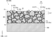
- FIG. 3 is an image diagram showing an example of the cross-sectional configuration of the wavelength conversion element according to the first embodiment.
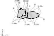
- FIG. 4 is an image diagram showing an example of positions where a plurality of phosphor particles and a plurality of thermally conductive particles are present in a part of the cross-sectional configuration of the wavelength conversion section according to the first embodiment.
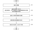
- FIG. 5 is a flowchart showing the manufacturing flow of the wavelength conversion element according to the first embodiment.
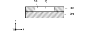
- FIG. 6 is a cross-sectional view showing an example of a state in the middle of manufacturing the wavelength conversion element.
- FIG. 1 is a schematic diagram showing an example of the configuration of a lighting system according to the first embodiment.
- FIG. 2 is a cross-sectional view showing an example of the configuration of the wavelength conversion element according to the
- FIG. 7 is a cross-sectional view showing an example of a state in the middle of manufacturing the wavelength conversion element.
- FIG. 8 is a cross-sectional view showing an example of a state in the middle of manufacturing the wavelength conversion element.
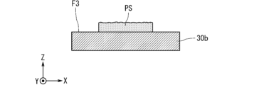
- FIG. 9 is a cross-sectional view showing an example of a state in the middle of manufacturing the wavelength conversion element.
- FIG. 10 is a cross-sectional view showing an example of a state in the middle of manufacturing the wavelength conversion element.
- FIG. 11 is a cross-sectional view schematically showing an image of the state of thermally conductive particles in a preliminary sintered body before pressure processing according to a reference example.
- FIG. 12 is a cross-sectional view schematically showing an image of the state of thermally conductive particles in a preliminary sintered body after pressure processing according to a reference example.
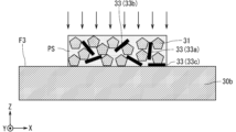
- FIG. 13 is a cross-sectional view schematically showing an image of the state of thermally conductive particles in the preliminary sintered body before pressure processing according to the first embodiment.
- FIG. 14 is a cross-sectional view schematically showing an image of the state of thermally conductive particles in the preliminary sintered body after pressure processing according to the first embodiment.
- FIG. 15 is a perspective view showing an example of the configuration of the wavelength conversion element according to the second embodiment.
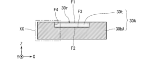
- FIG. 16 is a cross-sectional view showing an example of the configuration of the wavelength conversion element according to the second embodiment.
- FIG. 17 is a flowchart showing the manufacturing flow of the wavelength conversion element according to the second embodiment.
- FIG. 18 is a perspective view showing an example of the configuration of the base material according to the second embodiment.
- FIG. 19 is a cross-sectional view showing an example of the configuration of a base material according to the second embodiment.
- FIG. 20 is an image diagram showing an example of the cross-sectional configuration of the XX portion surrounded by the two-dot chain line in FIG.
- FIG. 21 is a cross-sectional view showing the configuration of a base material according to another first example.
- FIG. 22 is a cross-sectional view showing the configuration of a base material according to another second example.
- FIG. 23 is a cross-sectional view showing a configuration example of a wavelength conversion element according to another first example.
- FIG. 24 is a cross-sectional view showing a configuration example of a wavelength conversion element according to another first example.
- FIG. 25 is a cross-sectional view showing a configuration example of a wavelength conversion element according to another second example.
- FIG. 26 is a cross-sectional view showing a configuration example of a wavelength conversion element according to another second example.
- a wavelength conversion element that irradiates a phosphor with excitation light such as laser light and converts it into light with a wavelength different from that of the excitation light.
- the phosphor is a red phosphor that emits red fluorescence in response to irradiation with excitation light, a green phosphor that emits green fluorescence in response to irradiation with excitation light, and a blue phosphor that emits blue fluorescence in response to irradiation with excitation light. If the blue phosphor that emits fluorescence is included, the excitation light is converted into pseudo-white light by the wavelength conversion element.
- the phosphor can be degraded by the temperature rise caused by the irradiation of the excitation light. For this reason, the phosphor may be degraded due to temperature rise, for example, due to a longer irradiation time of the excitation light or a higher output of the irradiated excitation light.
- the inventor of the present disclosure has created a technology that can reduce the deterioration of the wavelength conversion element in the wavelength conversion element and the illumination system including the wavelength conversion element.
- FIG. 1 is a schematic diagram showing an example of the configuration of a lighting system 1 according to the first embodiment.
- the illumination system 1 radiates the fluorescence L1 generated by irradiating the wavelength conversion element 30 containing the phosphor with the excitation light L0 from the light source unit 2 into a predetermined space (also referred to as an illumination space) as the illumination light L2. is possible.
- the illumination system 1 may radiate the illumination light L2 to an indoor space, or may radiate the illumination light L2 to an outdoor space. In other words, the illumination light L2 emitted by the illumination system 1 may be used indoors or outdoors.
- the plurality of lighting systems 1 may emit the illumination light L2 to the same space, or the plurality of lighting systems 1 may emit the illumination light L2 to different spaces.
- the illumination system 1 includes, for example, a light source section 2, a conversion section 3, and an illumination section 4.
- the light source unit 2 can emit excitation light L0, for example.
- the light source unit 2 has, for example, a light emitting element.
- the light emitting element includes, for example, a laser diode (LD) or light emitting diode (LED) chip.
- Monochromatic light such as violet, bluish purple, or blue is applied to the excitation light L0 emitted by the light emitting element, for example.
- a gallium nitride (GaN)-based semiconductor laser that emits violet laser light of 405 nanometers (nm), for example, is applied to the light-emitting element.
- GaN gallium nitride
- pumping light L0 emitted from the light source unit 2 is transmitted to the conversion unit 3 via an optical transmission line (also referred to as a first optical transmission line) G1 such as an optical fiber.
- the light source unit 2 has a connecting portion to which the end portion of the first optical transmission line G1 into which the excitation light L0 is incident (also referred to as a first incident end portion) is connected.
- the conversion unit 3 has a wavelength conversion element 30, for example.
- the wavelength conversion element 30 can, for example, convert the applied excitation light L0 into light having a wavelength different from that of the excitation light L0.
- the wavelength conversion element 30 includes, for example, a phosphor that emits fluorescence with a wavelength different from that of the excitation light L0 in response to irradiation with the excitation light L0.
- the wavelength conversion element 30 includes, for example, a phosphor that emits red (R) fluorescence, green (G) fluorescence, and blue (B) fluorescence in response to irradiation with violet excitation light L0. If so, the wavelength conversion element 30 converts the violet excitation light L0 into pseudo-white light.
- R red
- G green
- B blue
- the fluorescence L1 emitted from the wavelength conversion element 30 in response to the irradiation of the excitation light L0 is transmitted through a light transmission line (also referred to as a second light transmission line) G2 such as an optical fiber to the illumination unit 4.
- the conversion unit 3 has, for example, a housing in which the wavelength conversion element 30 is fixed.
- the housing includes, for example, a first opening to which the end of the first optical transmission line G1 from which the excitation light L0 is emitted (also referred to as a first emission end) is connected; and a second opening to which the end of the two optical transmission paths G2 on which the fluorescence L1 is incident (also referred to as a second incident end) is connected.
- An optical element such as a mirror is arranged inside the housing for collecting the fluorescence L1 emitted from the wavelength conversion element 30 in response to the irradiation of the excitation light L0 to the second incident end of the second optical transmission line G2.
- the illumination unit 4 can emit fluorescence L1 emitted from the wavelength conversion element 30 in response to irradiation with the excitation light L0 emitted from the light source unit 2 toward a predetermined illumination space.
- the lighting unit 4 has, for example, a main body and an optical element.
- the main body has, for example, a connection portion to which the end portion (also referred to as the second emission end portion) of the second optical transmission line G2 from which the fluorescence L1 is emitted is connected.
- a tubular member may be applied to the main body.
- the optical element is attached to, for example, the main body, and emits fluorescence L1 emitted from the second emission end of the second optical transmission line G2 toward a predetermined illumination space as illumination light L2.
- the lighting system 1 may also include a control device 5 for controlling the operation of the light source unit 2, for example.
- the control device 5 has, for example, a control section 51 and a drive section 52 .
- the control unit 51 can control the operation of the control device 5 in an integrated manner by controlling other components of the control device 5 .
- the control unit 51 includes, for example, a CPU (Central Processing Unit) 511 and a storage unit 512 .
- Storage unit 512 includes non-temporary recording media readable by CPU 511, such as ROM (Read Only Memory) and RAM (Random Access Memory).
- the storage unit 512 stores a program Pg1 for controlling the control device 5 and the like.
- Various functions of the control unit 51 are realized by the CPU 511 executing the program Pg1 in the storage unit 512 .
- the drive unit 52 can drive the light source unit 2 according to an instruction from the control unit 51, for example.
- the drive unit 52 supplies power from the power source to the light source unit 2 to drive the light source unit 2 and cause the light source unit 2 to output the excitation light L0.
- the control unit 51 can control the timing at which the light source unit 2 emits the excitation light L0 by controlling whether power is supplied from the power source to the light source unit 2 through the driving unit 52 .
- FIG. 2 is a cross-sectional view showing an example of the configuration of the wavelength conversion element 30 according to the first embodiment.
- FIG. 2 schematically depicts the periphery of the first output end of the first optical transmission line G1 and the periphery of the second incident end of the second optical transmission line G2.
- the wavelength conversion element 30 includes a wavelength conversion portion 30t and a substrate 30b.
- the cross-sectional structure of the wavelength converting portion 30t has a complicated structure in which microstructures are intricate, schematic illustration of the structure is omitted in FIG. 2 for the sake of convenience.
- the wavelength conversion unit 30t has a surface (also referred to as a first surface) F1 on which the excitation light L0 is incident. Further, the wavelength converting portion 30t has a surface (also referred to as a second surface) F2 located on the opposite side of the first surface F1.
- the wavelength converting portion 30t has, for example, a plate-like or film-like shape having a thickness along the direction from the second surface F2 to the first surface F1.
- the base material 30b has a surface (also referred to as a third surface) F3 on which the wavelength converting portion 30t is arranged. Specifically, the second surface F2 of the wavelength converting portion 30t is fixed to the third surface F3.
- a surface F1 on which the excitation light L0 is incident.
- the wavelength converting portion 30t has a surface (also referred to as a second surface) F2 located on the opposite side of the first surface F1.
- the wavelength converting portion 30t has, for example, a plate-like or film-like shape
- the first surface F1 faces the +Z direction
- the second surface F2 faces the -Z direction
- the third surface F3 faces the +Z direction.
- a plate-shaped member is applied to the base material 30b, for example.
- the plate-shaped member for example, a disk-shaped member or a rectangular member in a plan view is applied.
- the base material 30b is a member to which the wavelength conversion part 30t is fixed.
- the base material 30b has, for example, a higher thermal conductivity than the wavelength conversion section 30t. Thereby, the base material 30b has a function as a heat sink that emits heat from the wavelength converting section 30t, for example.
- FIG. 3 is an image diagram schematically showing an example of the cross-sectional configuration of the wavelength conversion element 30 according to the first embodiment.
- FIG. 3 shows a cross-sectional image drawn based on a scanning electron microscope (SEM) photograph of the cross-section of the wavelength conversion unit 30t.
- SEM scanning electron microscope
- the wavelength conversion part 30t includes a plurality of phosphor particles 31, glass 32, and a plurality of thermally conductive particles 33.
- the base material 30b is hatched with diagonal lines slanted to the right
- the plurality of phosphor particles 31 is hatched with diagonal lines slanted to the left
- the glass 32 is hatched with sand.
- a plurality of thermally conductive particles 33 are drawn with straight thick lines or solid lines.
- Each of the plurality of phosphor particles 31 is, for example, a phosphor particle (also referred to as a phosphor particle) that emits fluorescence in response to irradiation with the excitation light L0.
- the plurality of phosphor particles 31 includes, for example, one or more types of phosphor particles that emit fluorescence with one or more wavelength spectra different from the wavelength spectrum of the excitation light L0 in response to irradiation with the excitation light L0.
- the one or more types of phosphor particles may include, for example, multiple types of phosphor particles that emit fluorescence having different wavelength spectra in response to irradiation with the excitation light L0.
- the multiple types of phosphor particles include, for example, red phosphor particles, green phosphor particles, and blue phosphor particles.
- the red phosphor is a phosphor that emits red (R) fluorescence in response to irradiation with the excitation light L0.
- the green phosphor is a phosphor that emits green (G) fluorescence in response to irradiation with the excitation light L0.
- the blue phosphor is a phosphor that emits blue (B) fluorescence in response to irradiation with the excitation light L0.
- Phosphors constituting the plurality of phosphor particles 31 include, for example, rare earths such as Eu (europium), Ce (cerium) or Y (yttrium), phosphates, oxides, silicates, nitrides, fluorides. Phosphors are applied, including as compounds such as oxides, aluminates or sulfides.
- the particle size of the phosphor particles 31 is, for example, about 5 micrometers ( ⁇ m) to 50 ⁇ m.
- the plurality of phosphor particles 31 includes, for example, two phosphor particles 31 aligned in the direction along the first surface F1. Two phosphor particles 31 aligned in the direction along the first surface F1 face each other in the direction along the first surface F1 without sandwiching another phosphor particle 31 therebetween.
- the direction along the first surface F1 is the direction along the XY plane.
- the directions along the first surface F1 are the directions along the ⁇ X directions.
- the direction along the first surface F1 is not limited to the direction extending parallel to the first surface F1.
- the direction along the first plane F1 may include a direction inclined from 0 degrees to 15 degrees with respect to the first plane F1, or a direction inclined from 0 degrees to 30 degrees with respect to the first plane F1. It may also include tilted directions within degrees.
- the direction along the first surface F1 is not limited to the direction extending parallel to the XY plane.
- the direction along the first plane F1 may include a direction that is inclined within the range of 0 degrees to 15 degrees with respect to the XY plane, or within the range of 0 degrees to 30 degrees with respect to the XY plane. may include a tilted direction.
- the direction along the first plane F1 includes a direction inclined within the range of 0 to 15 degrees with respect to a virtual line parallel to the X-axis (also referred to as a virtual line). , or may include a direction inclined within the range of 0 to 30 degrees with respect to a virtual line parallel to the X-axis.
- focusing on the upper right portion of the wavelength conversion part 30t in FIG. It includes body particles P1 and second phosphor particles P2.
- the first phosphor particles P1 and the second phosphor particles P2 face each other in the direction along the first surface F1 without sandwiching another phosphor particle 31 therebetween.
- phosphor particles P3 and a fourth phosphor particle P4 face each other in the direction along the first surface F1 without sandwiching another phosphor particle 31 therebetween.
- the glass 32 bonds, for example, a plurality of phosphor particles 31 together.
- the glass 32 is positioned, for example, between the plurality of phosphor particles 31 and between the phosphor particles 31 and the substrate 30b.
- the glass 32 has a function of directly conducting the heat of the phosphor particles 31 at the portion in direct contact with the phosphor particles 31 .
- the surfaces of the phosphor particles 31 may be covered with a coating layer.
- the state in which "the glass 32 is in direct contact with the phosphor particles 31" includes the state in which the coating layer that covers the phosphor particles 31 and the glass 32 are in direct contact.
- the glass 32 transmits the excitation light L0 to the inside of the wavelength conversion unit 30t, and emits the fluorescence L1 emitted by the phosphor particles 31 excited in response to the irradiation of the excitation light L0 to the outside of the wavelength conversion unit 30t. Because of the transparency.
- the first surface F1 of the wavelength conversion unit 30t is irradiated with the excitation light L0, the heat generated by the irradiation of the excitation light L0 applied to the plurality of phosphor particles 31 and the glass 32 is transferred to the substrate through the glass 32 and the like. The heat is conducted to 30b and radiated.
- Each of the plurality of thermally conductive particles 33 is located at one or more of, for example, within the glass 32, at the boundary between the plurality of phosphor particles 31 and the glass 32, and between the two phosphor particles 31. are doing.
- Each of the multiple thermally conductive particles 33 is a particle having thermal conductivity superior to that of the glass 32 .
- Boron nitride having a hexagonal crystal structure also referred to as hexagonal boron nitride or h-BN, for example, is applied to each of the plurality of thermally conductive particles 33 .
- the thermally conductive particles 33 have the function of directly conducting the heat of the phosphor particles 31 at the portion in direct contact with the phosphor particles 31 , and conduct the heat through the glass 32 at the portion in contact with the glass 32 . It has a function of indirectly conducting the heat of the phosphor particles 31 through them.
- Hexagonal boron nitride particles for example, have a plate-like shape and exhibit high thermal conductivity in the direction along the plate surface (also referred to as the direction along the ab plane and the direction along the (002) plane).
- the thermally conductive particles 33 have high thermal conductivity in the direction along the plate surface.
- the length along the plate surface of each of the plurality of thermally conductive particles 33 may be, for example, about 1 ⁇ m to 10 ⁇ m, or about 5 ⁇ m to 6 ⁇ m.
- the plurality of thermally conductive particles 33 are arranged along the direction perpendicular to the first surface F1. It includes located thermally conductive particles (also referred to as first thermally conductive particles) 33a.
- thermally conductive particles also referred to as first thermally conductive particles
- the plate surface of the first thermally conductive particles 33a is positioned along the direction perpendicular to the first surface F1.
- the glass 32 may or may not exist between the two phosphor particles 31 and the first thermally conductive particles 33a.
- the direction perpendicular to the first surface F1 is the direction along the ⁇ Z direction as the thickness direction of the wavelength converting portion 30t.
- the state in which the thermally conductive particles 33 are positioned along the direction perpendicular to the first surface F1 is a virtual plane (also referred to as a virtual plane) perpendicular to the first surface F1 and the thermally conductive particles 33 It is not limited to a state in which the plate surface of the plate is completely matched.
- the state in which the thermally conductive particles 33 are positioned along the direction perpendicular to the first surface F1 is the imaginary line parallel to the Z-axis and the plate surface of the thermally conductive particles 33. is not limited to a state in which the are completely matched.
- the state in which the thermally conductive particles 33 are positioned along the direction perpendicular to the first surface F1 is an imaginary plane inclined within the range of 0 to 15 degrees with respect to the imaginary plane perpendicular to the first surface F1. It may include a state in which the plane and the plate surface of the thermally conductive particles 33 are aligned, or a virtual plane inclined within the range of 0 degrees to 30 degrees with respect to the virtual plane perpendicular to the first surface F1. and the plate surface of the thermally conductive particles 33 may include a state in which they are aligned.
- FIG. 1 In the cross-sectional structure of FIG.
- the state in which the thermally conductive particles 33 are positioned along the direction perpendicular to the first surface F1 corresponds to a virtual line inclined within the range of 0 to 15 degrees with respect to the Z axis. It may include a state in which the plate surfaces of the thermally conductive particles 33 are aligned, or a virtual line inclined within the range of 0 to 30 degrees with respect to the Z-axis and the plate surfaces of the thermally conductive particles 33 may include a state in which
- the plurality of thermally conductive particles 33 are, for example, between a first phosphor particle P1 and a second phosphor particle P2 as two phosphor particles 31 aligned in the ⁇ X direction. , the first thermally conductive particles 33a located along the ⁇ Z directions. In addition, the plurality of thermally conductive particles 33 are arranged in the ⁇ Z direction between the third phosphor particle P3 and the fourth phosphor particle P4 as the two phosphor particles 31 aligned in the ⁇ X direction, for example. It has first thermally conductive particles 33a located along the .
- the first thermally conductive particles 33a have, for example, a plate surface along the direction from the first surface F1 to the second surface F2. In other words, the first thermally conductive particles 33a have, for example, a plate surface along the thickness direction of the wavelength converting portion 30t. Therefore, for example, the first thermally conductive particles 33a can increase heat conduction in the direction from the first surface F1 to the second surface F2 in the wavelength conversion section 30t. In other words, the first thermally conductive particles 33a can increase heat conduction in the thickness direction of the wavelength converting portion 30t. As a result, for example, the heat dissipation performance of the wavelength conversion section 30t can be improved.
- the temperature rise of the plurality of phosphor particles 31 can be reduced when the first surface F1 of the wavelength conversion unit 30t is irradiated with the excitation light L0. Therefore, for example, the phosphor particles 31 are less likely to deteriorate, and deterioration of the wavelength conversion element 30 can be reduced.
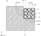
- FIG. 4 is an image diagram showing an example of positions where a plurality of phosphor particles 31 and a plurality of thermally conductive particles 33 are present in a part of the cross-sectional configuration of the wavelength conversion section 30t according to the first embodiment.
- FIG. 4 shows three phosphor particles 31 and a plurality of thermally conductive particles 33 around the three phosphor particles 31 drawn based on a scanning electron microscope (SEM) photograph of the cross section of the wavelength conversion part 30t. Only the images of the existing locations are shown. In FIG. 4, the existence of the glass 32 is omitted for convenience.
- a plurality of phosphor particles 31 are hatched with oblique lines rising to the left, and a plurality of thermally conductive particles 33 are drawn with straight thick or solid lines.
- the plurality of thermally conductive particles 33 are in contact with the surface of one phosphor particle 31 of the plurality of phosphor particles 31, one or more heat particles.
- Conductive particles (also referred to as second thermally conductive particles) 33b may be included. If this configuration is adopted, for example, heat dissipation from one phosphor particle 31 to the glass 32 or the like via one or more second thermally conductive particles 33b can be increased. Thereby, for example, the temperature rise of the phosphor particles 31 can be reduced. As a result, deterioration of the phosphor particles 31 can be reduced, and deterioration of the wavelength conversion element 30 can be reduced.
- one or more second thermally conductive particles 33b may be in contact with the surfaces of all the phosphor particles 31 among the plurality of phosphor particles 31 in the wavelength conversion section 30t,
- One or more second thermally conductive particles 33b may be in contact with the surface of each of two or more phosphor particles 31 of the plurality of phosphor particles 31 in the wavelength converting portion 30t.
- the number of phosphor particles 31 having surfaces in contact with one or more second thermally conductive particles 33b is not limited to one. Then, for example, as the number of phosphor particles 31 having surfaces in contact with one or more second thermally conductive particles 33b increases, deterioration of more phosphor particles 31 is reduced, and the wavelength conversion element 30 degradation can be reduced.
- each particle 33b may have an elongated rod-like shape having a longitudinal direction and a lateral direction.
- the lateral direction may be a direction along a direction perpendicular to the longitudinal direction.
- the cross section of the wavelength conversion part 30t along the virtual plane perpendicular to the first plane F1 is the plane along the XZ plane.
- the longitudinal direction of each of the one or more second thermally conductive particles 33b is the surface of one phosphor particle 31 with which the one or more second thermally conductive particles 33b are in contact.
- this configuration may be in the direction along If this configuration is adopted, for example, by increasing the area of the surface of one phosphor particle 31 in contact with one or more second thermally conductive particles 33b, one phosphor particle 31 to the glass 32 or the like via one or more second thermally conductive particles 33b. Thereby, for example, the temperature rise of the phosphor particles 31 can be reduced. As a result, deterioration of the phosphor particles 31 can be reduced, and deterioration of the wavelength conversion element 30 can be reduced.
- the cross section of the wavelength converting portion 30t along the virtual plane perpendicular to the first surface F1 is the cross section of the wavelength converting portion 30t inclined within the range of 0 to 15 degrees with respect to the virtual plane perpendicular to the first surface F1.
- the cross section of the wavelength converting portion 30t may be inclined within the range of 0 to 30 degrees with respect to a virtual plane perpendicular to the first surface F1.
- the cross section of the wavelength converting portion 30t along the virtual plane perpendicular to the first surface F1 is not limited to the cross section of the wavelength converting portion 30t perpendicular to the first surface F1.
- one or more second heat Conductive particles 33b may be in contact. If this configuration is adopted, for example, one phosphor particle 31 is in contact with one or more second thermally conductive particles 33 b in an area of 10% or more of the surface of one phosphor particle 31 . to the glass 32 or the like via one or more second thermally conductive particles 33b. Thereby, for example, the temperature rise of the phosphor particles 31 can be reduced. As a result, deterioration of the phosphor particles 31 can be reduced, and deterioration of the wavelength conversion element 30 can be reduced.
- one or more second thermally conductive particles 33 b are in contact with 70% or less of the surface of one phosphor particle 31 , so that the surface of one phosphor particle 31 is in contact with the glass 32 .
- the area of the contacting region can be secured, and the strength of bonding between the plurality of phosphor particles 31 via the glass 32 can be secured to some extent.
- the durability of the wavelength conversion unit 30t can be improved. Therefore, deterioration of the wavelength conversion element 30 can be reduced and the durability of the wavelength conversion element 30 can be improved.
- one or more second thermal The conductive particles 33b may be in contact with each other, or from 10% of each surface of some two or more phosphor particles 31 among the plurality of phosphor particles 31 present in the wavelength converting portion 30t.
- the 70% area may be in contact with one or more second thermally conductive particles 33b.
- the number of phosphor particles 31 that are in contact with one or more second thermally conductive particles 33b over 10% to 70% of the surface area is not limited to one.
- the number of phosphor particles 31 in which one or more second thermally conductive particles 33b are in contact with an area of 10% to 70% of the surface increases, deterioration of the wavelength conversion element 30 is reduced and The durability of the wavelength conversion element 30 can be improved.
- the plurality of thermally conductive particles 33 may include two or more thermally conductive particles 33 aggregated in contact with each other in the lateral direction. . If this configuration is adopted, for example, the heat transfer and heat conduction in the lateral direction of the two or more heat conductive particles are increased by the two or more heat conductive particles 33 that are aggregated, so that a plurality of fluorescence Heat dissipation from body particles 31 may be increased.
- the two or more aggregated thermally conductive particles 33 can increase the heat conduction in the direction from the first surface F1 to the second surface F2 in the wavelength converting portion 30t.
- the two or more aggregated heat conductive particles 33 can increase the heat conduction in the thickness direction in the wavelength conversion section 30t. As a result, for example, the heat dissipation performance of the wavelength conversion section 30t can be improved.
- the temperature rise of the plurality of phosphor particles 31 can be reduced when the first surface F1 of the wavelength conversion unit 30t is irradiated with the excitation light L0. Therefore, for example, the phosphor particles 31 are less likely to deteriorate, and deterioration of the wavelength conversion element 30 can be reduced.
- the longitudinal direction of the thermally conductive particles 33 may be located.
- the second thermally conductive particle 33 extends over the entire longitudinal direction of the first thermally conductive particle 33. may be in contact with each other, or a second thermally conductive particle 33 may be in contact with a partial region in the longitudinal direction of the first thermally conductive particle 33 .
- the second surface F2 of the wavelength conversion part 30t opposite to the first surface F1 is fixed to the base material 30b functioning as a heat sink.
- the presence of the first thermally conductive particles 33a positioned along the direction from the first surface F1 toward the base material 30b can increase the heat radiation of the wavelength conversion part 30t through the base material 30b.
- the temperature rise of the plurality of phosphor particles 31 can be reduced when the first surface F1 of the wavelength conversion unit 30t is irradiated with the excitation light L0.
- the phosphor particles 31 are less likely to deteriorate, and deterioration of the wavelength conversion element 30 can be reduced.
- the plurality of thermally conductive particles 33 are thermally conductive particles (also referred to as third thermally conductive particles) positioned along the third surface F3 of the substrate 30b. ) 33c. If this configuration is adopted, for example, in a wider area of the third surface F3 to which the wavelength conversion section 30t is fixed in the base material 30b, the heat transfer from the wavelength conversion section 30t can be increased. Heat dissipation from the conversion unit 30t may increase. Thereby, for example, the temperature rise of the phosphor particles 31 when the first surface F1 of the wavelength conversion unit 30t is irradiated with the excitation light L0 can be reduced. As a result, for example, the phosphor particles 31 are less likely to deteriorate, and deterioration of the wavelength conversion element 30 can be reduced.
- the glass 32 may or may not exist between the third surface F3 and the third thermally conductive particles 33c.
- the state in which the thermally conductive particles 33 are positioned along the third surface F3 is a state in which the imaginary plane parallel to the third surface F3 completely coincides with the plate surface of the thermally conductive particles 33. is not limited to In the cross-sectional structure of FIG. 3, when the thermally conductive particles 33 are positioned along the third surface F3, the imaginary line parallel to the X-axis completely coincides with the plate surface of the thermally conductive particles 33.
- a state in which the thermally conductive particles 33 are positioned along the third surface F3 is an imaginary plane inclined within the range of 0 to 15 degrees with respect to the third surface F3 and a plate of the thermally conductive particles 33. It may include a state in which the surface of the thermally conductive particles 33 is aligned with the surface of the thermally conductive particles 33, and the imaginary plane inclined within the range of 0 to 30 degrees with respect to the third surface F3 is aligned. may include the state of being In the cross-sectional structure of FIG.
- the state in which the thermally conductive particles 33 are positioned along the third surface F3 is defined by a virtual line inclined within the range of 0 to 15 degrees with respect to the X-axis and the thermally conductive particles It may include a state in which the surface of the thermally conductive particles 33 coincides with the surface of the thermally conductive particles 33, or the imaginary line inclined within the range of 0 to 30 degrees with respect to the X-axis coincides with the surface of the thermally conductive particles 33. It may contain the state of
- the wavelength conversion section 30t may have, for example, an air gap.
- a void is a portion of the wavelength converting portion 30t that is a space where none of the phosphor particles 31, the glass 32, and the thermally conductive particles 33 exist.
- the voids are, for example, between two phosphor particles 31, in glass 32, between phosphor particles 31 and glass 32, between two thermally conductive particles 33, and between phosphor particles 31 and thermally conductive particles 33. and between the glass 32 and the thermally conductive particles 33.
- FIG. 5 is a flowchart showing the manufacturing flow of the wavelength conversion element 30 according to the first embodiment.
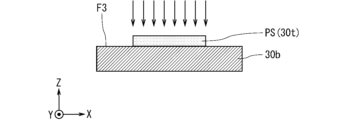
- 6 to 10 are cross-sectional views each showing an example of a state during the manufacture of the wavelength conversion element 30.
- FIG. Hereinafter, a method for manufacturing the wavelength conversion element 30 will be described using FIGS. 6 to 10 while referring to FIG.
- a base material 30b is prepared (step S1).
- a metal material for example, is applied to the material of the base material 30b.
- this metal material include copper (Cu), aluminum (Al), magnesium (Mg), gold (Au), silver (Ag), iron (Fe), chromium (Cr), cobalt (Co), beryllium ( Be), molybdenum (Mo), tungsten (W) or alloys, etc. are applied.
- the base material 30b can be easily produced by a casting method such as die casting.
- the reflectance of visible light on the surface of the substrate 30b can be increased.
- the reflectance of visible light may be improved by processing the surface of the base material 30b into a mirror surface by physical polishing or chemical polishing.
- Examples of materials for the base material 30b include aluminum nitride (AlN), gallium nitride (GaN), silicon carbide ( SiC ), silicon nitride ( Si3N4 ), carbon (C), and sapphire ( Al2O3 ). , magnesia (MgO) or garnet may be employed.
- the non-metallic material may be, for example, a crystalline material or an amorphous material without crystallinity.
- SiC or Si 3 N 4 may be employed as the non-metallic material having crystallinity. Since these non-metallic materials have low reflectance to visible light, for example, when using AlN, an optical reflective film may be formed on the surface.
- the shape and size of the base material 30b can be appropriately set according to the size of the wavelength conversion element 30.
- FIG. For example, in the case of the base material 30b having a rectangular shape in plan view, the thickness of the base material 30b is set to about 0.1 millimeter (mm) to 5 mm, and the vertical and horizontal lengths of the base material 30b are It may be set to about 0.5 mm to 30 mm.
- an opening 30o corresponding to the planar view shape of the wavelength converting portion 30t is formed on the third surface F3 as the main surface of the substrate 30b on which the wavelength converting portion 30t is formed. are superimposed on each other (step S2).
- Aluminum for example, is applied to the material of the mask 30m.
- an opening 30o having a desired plan view shape can be formed by etching or the like.
- the thickness of the mask 30m is set larger than the thickness of the wavelength conversion section 30t. For example, if the thickness of the wavelength converting portion 30t is 0.1 mm, the thickness of the mask 30m is set from 0.15 mm to 0.2 mm.
- the material of the mask 30m may be resin.
- the material of the mask is not limited as long as the opening 30o can be formed in a desired shape and has the strength to withstand the subsequent powder filling process.
- powder of one or more types of phosphor particles also referred to as phosphor powder
- powder of glass also referred to as glass powder
- powder of thermally conductive particles thermally conductive particles
- sufficiently mixed powder also referred to as mixed powder
- the content of the phosphor powder is about 45 wt% to 85 wt%
- the content of the glass powder is about 10 wt% to 45 wt%
- the content of the thermal conductive powder is about 45 wt% to 85 wt%.
- the content is from 1 wt% to 20 wt%.
- the phosphor powder includes, for example, red phosphor particles, green phosphor particles, and blue phosphor particles.
- red phosphor for example, a phosphor having a fluorescence wavelength peak in the range of about 620 nm to 750 nm when irradiated with the excitation light L0 is applied.
- Green phosphor for example, a phosphor having a fluorescence wavelength peak in the range of about 495 nm to 570 nm when irradiated with the excitation light L0 is applied.
- Green phosphor materials include, for example, ⁇ -sialon ( ⁇ -SiAlON:Eu), SrSi 2 (O, Cl) 2 N 2 :Eu, (Sr, Ba, Mg) 2 SiO 4 :Eu 2 2+ and ZnS. : Cu, Al or Zn2SiO4 :Mn or the like is applied.
- the blue phosphor for example, a phosphor having a fluorescence wavelength peak in the range of about 450 nm to 495 nm when irradiated with the excitation light L0 is applied.
- Materials for the blue phosphor include, for example, (Ba, Sr)MgAl 10 O 17 :Eu, BaMgAl 10 O 17 :Eu, (Sr, Ca, Ba) 10 (PO 4 ) 6 Cl 2 :Eu, (Sr, Ba) 10 (PO 4 ) 6 Cl 2 :Eu or ⁇ -sialon, etc. are applied.
- the particle size distribution of the phosphor powder may have various particle size distributions.
- the phosphor powder may contain phosphor particles with a 50% particle size (D50) in the range of 0.1 ⁇ m to 100 ⁇ m, or may contain phosphor particles with a D50 in the range of 10 ⁇ m to 30 ⁇ m. good.
- D50 50% particle size
- low-melting-point glass powder that has transparency after sintering is applied.
- Oxide glass having a melting point of 200° C. (200° C.) to 700° C. is applied to the low-melting glass.
- the low-melting-point glass for example, glass containing a plurality of components selected from tin oxide, zinc oxide, boron oxide, bismuth oxide, boron oxide, vanadium oxide, tellurium oxide, and phosphoric acid as main components can be employed.
- the low-melting-point glass may contain, for example, an alkali metal oxide.
- tin-phosphate-based low-melting-point glass is applied to the glass powder.
- the particle size distribution of the glass powder may have various particle size distributions similar to the particle size distribution of the phosphor powder.
- the glass powder may contain glass particles with a D50 in the range of 0.1 ⁇ m to 100 ⁇ m, or may contain glass particles with a D50 in the range of 10 ⁇ m to 20 ⁇ m.
- thermally conductive powder for example, powder of hexagonal boron nitride (h-BN) particles as thermally conductive particles is applied.
- the hexagonal boron nitride particles have a plate-like shape.
- the particle size distribution of the thermally conductive powder may have various particle size distributions.
- the thermally conductive powder may comprise thermally conductive particles with a 50% particle size (D50) in the range of 1 ⁇ m to 10 ⁇ m, or thermally conductive particles with a D50 in the range of 5 ⁇ m to 6 ⁇ m. good too.
- a vibration method, a rotation-oscillation method, or the like can be used for mixing the phosphor powder, the glass powder, and the thermally conductive powder.
- media may be used when mixing the phosphor powder, the glass powder, and the thermally conductive powder. Examples of the media include a dry method of directly mixing powders and a wet method of mixing with a solvent or binder. , can be used in a variety of ways.
- the mask 30m is removed from the base material 30b on which the powder-filled body PW is formed (step S4), and the powder-filled body PW is heated to form the pre-sintered body PS (step S5).
- the heating temperature is set to a temperature equal to or higher than the melting point of the glass powder and lower than the temperature at which the phosphor particles lose their fluorescence function.
- the heating temperature may be about 260°C to 600°C, or about 350°C to 450°C.
- the heating of the powder-filled body PW and the pre-sintered body PS and the pressure processing described below can be performed, for example, in a common chamber.
- This chamber may or may not be a vacuum vessel.
- the inside of the chamber can be evacuated during heating.
- the inside of the chamber is evacuated and heated, the generation of air bubbles when the glass powder is melted can be reduced.
- the heating and pressurization of the powder-filled body PW and pre-sintered body PS may be performed in the atmosphere, for example.
- the heating and pressurization of the powder-filled body PW and the preliminary sintered body PS may be performed using, for example, a multi-purpose high-temperature sintering furnace, or may be performed using a heater block and a hand press.
- the preliminary sintered body PS is pressurized on the substrate 30b while maintaining the set temperature (step S6).
- the pressure during pressure processing can be set to a pressure that does not physically crush the phosphor particles and lose the fluorescence function.
- the pressure during pressure processing is set to about 20 kgf/cm 2 to 300 kgf/cm 2 (about 2 MPa to about 30 MPa).
- the pre-sintered body PS is held in a state of being pressurized for a period of, for example, about 1 second to 10 minutes.
- the temporary sintered body PS is cooled while maintaining the pressure applied to the temporary sintered body PS during pressure processing (step S7), and when the temperature of the temporary sintered body PS becomes lower than the melting point of the glass powder, the pressure is released. unlock. As a result, the temporary sintered body PS becomes the wavelength converting portion 30t.
- the wavelength conversion element 30 can be manufactured through the above steps.
- the content of the phosphor powder is about 5 wt%
- the content of the glass powder is about 75 wt% to 94 wt%
- the content of the thermally conductive powder is about 1 wt% to 94 wt%.
- a reference example of 20 wt % is adopted.
- FIG. 11 is a cross-sectional view schematically showing an image of the state of the thermally conductive particles 33 in the preliminary sintered body PS before pressure processing according to a reference example.
- FIG. 12 is a cross-sectional view schematically showing an image of the state of the thermally conductive particles 33 in the preliminary sintered body PS after pressure processing according to a reference example.
- FIGS. 11 and 12 since the content of the plurality of phosphor particles in the pre-sintered body PS is low, illustration of the plurality of phosphor particles is omitted.
- a plurality of plate-shaped thermally conductive particles 33 are positioned in random directions.
- the heating temperature of the temporary sintered body PS is equal to or higher than the melting point of the glass powder at the time of pressure processing, the glass is in a state in which it can melt and flow.
- the preliminary sintered body PS is pressurized to apply a pressing force in the ⁇ Z direction, as shown in FIG. It becomes a form positioned along a direction perpendicular to the direction in which the pressing force is applied.
- each of the plurality of plate-like thermally conductive particles 33 can be arranged along the direction perpendicular to the thickness direction of the preliminary sintered body PS.
- FIG. 13 is a cross-sectional view schematically showing an image of the state of the thermally conductive particles 33 in the preliminary sintered body PS before pressure processing according to the first embodiment.
- FIG. 14 is a cross-sectional view schematically showing an image of the state of the thermally conductive particles 33 in the preliminary sintered body PS after pressure processing according to the first embodiment.
- each of the plurality of phosphor particles 31 is a regular pentagon hatched with diagonal lines rising to the left. It is shown.
- a plurality of plate-like thermally conductive particles 33 are positioned in random directions.
- the heating temperature of the temporary sintered body PS is equal to or higher than the melting point of the glass powder at the time of pressure processing, the glass is in a state in which it can melt and flow.
- the preliminary sintered body PS is subjected to pressure processing that applies a pressing force in the -Z direction.
- FIG. 14 even if the preliminary sintered body PS is pressurized to apply a pressing force in the ⁇ Z direction, the presence of the plurality of phosphor particles 31 causes a plate-like shape.
- the plurality of thermally conductive particles 33 may include first thermally conductive particles 33a arranged along the thickness direction of the preliminary sintered body PS.
- the first thermally conductive particles 33a have plate surfaces along the direction perpendicular to the first surface F1, so that the wavelength converting portion 30t has a plate surface extending from the first surface F1 to the second surface F2. Heat conduction in the direction of thickness can be increased.
- the plurality of thermally conductive particles 33 are in contact with the surfaces of the phosphor particles 31 and are in contact with the surface of the phosphor particles 31. It may be in a state of containing thermally conductive particles 33b.
- the presintered body PS is pressurized, if the content of the plurality of phosphor particles 31 in the presintered body PS is high to some extent, the locations where the intervals between the plurality of phosphor particles 31 are narrow increase. obtain.
- the number of the one or more second thermally conductive particles 33b in contact with the surfaces of the phosphor particles 31 can be increased in the pre-sintered body PS after pressure processing.
- the presintered body PS is subjected to pressure processing, if the content of the plurality of thermally conductive particles 33 in the presintered body PS is high to some extent, the presintered body PS after pressure processing , the number of one or more second thermally conductive particles 33b in contact with the surface of the phosphor particles 31 may increase.
- the cross section of the pre-sintered body PS after pressure processing may be in a direction along the surface of one phosphor particle 31 with which the thermally conductive particles 33b are in contact.
- the presintered body PS is pressurized, if the content of the plurality of phosphor particles 31 in the presintered body PS is high to some extent, the locations where the intervals between the plurality of phosphor particles 31 are narrow increase. obtain.
- one or more that are in contact with one phosphor particle 31 and have a longitudinal direction along the surface of the one phosphor particle 31 of the second thermally conductive particles 33b can be increased.
- the presintered body PS is subjected to pressure processing, if the content of the plurality of thermally conductive particles 33 in the presintered body PS is high to some extent, the presintered body PS after pressure processing , the number of one or more second thermally conductive particles 33b in contact with one phosphor particle 31 and having a longitudinal direction along the surface of the one phosphor particle 31 can be increased.
- one or more phosphor particles 31 have one or more may be in contact with the second thermally conductive particles 33b.
- the number of phosphor particles 31 with one or more second thermally conductive particles 33b in contact with 10% to 70% of the surface area can be increased.
- the pre-sintered body PS after pressure processing may be in a state including two or more thermally conductive particles 33 agglomerated while contacting each other in one direction.
- the content of the plurality of thermally conductive particles 33 in the pre-sintered body PS is high to some extent, in the cross section of the pre-sintered body PS after pressure processing , the number of two or more thermally conductive particles 33 aggregated in contact with each other in the direction along the lateral direction of the thermally conductive particles 33 may increase.
- the phosphor particles 31 were located between the phosphor particles 31 and the third surface F3 of the substrate 30b near the substrate 30b.
- the thermally conductive particles 33 can be pressurized to become third thermally conductive particles 33c positioned along the third surface F3.
- the heat transfer from the wavelength converting part 30t can be increased. Heat dissipation can increase.
- the base material 30b and the wavelength conversion section 30t are bonded by an oxidation bond.
- the base material 30b and the wavelength converting section 30t are bonded by oxidation bonding between the oxygen in the oxide film formed on the surface of the base material 30b by heating and the oxygen in the oxide glass.
- the surface of the substrate 30b is provided with fine unevenness of, for example, several ⁇ m, and the glass is entangled therewith.
- the bonding force between the base material 30b and the wavelength converting portion 30t may be enhanced by the anchor effect.
- the surface of the base material 30b may have an uneven shape (fine unevenness).
- the size of the fine irregularities referred to here may be a size that allows the low-melting-point glass that is liquefied during heating to flow and enter into the fine irregularities.
- the size of minute unevenness can be set, for example, from 0.1 ⁇ m to 50 ⁇ m.
- the size of the fine unevenness may be set to a size that allows the phosphor particles to enter the fine unevenness.
- the size of minute unevenness can be set to, for example, 5 ⁇ m to 50 ⁇ m.
- the size of the minute unevenness (unevenness of the uneven shape) of the substrate 30b here is, for example, the bottom (lowest point) of the concave portion of the minute unevenness and the top of the convex portion (lowest point) in the thickness direction of the substrate 30b. highest point).
- the wavelength conversion part 30t and the base material 30b may be prepared separately.
- the powder-filled body PW is formed separately from the base material 30b, and the powder-filled body PW is heated to form the preliminary sintered body PS. and pressurizing the temporary sintered body PS to obtain the wavelength converting portion 30t.
- a metal multilayer film may be formed on the surface of the wavelength conversion section 30t facing the substrate 30b, and the wavelength conversion section 30t and the substrate 30b may be joined by soldering.
- a multilayer film (also referred to as a Ti/Pt/Au multilayer film) in which thin films are laminated in order of titanium (Ti), platinum (Pt), and gold (Au) from the wavelength conversion section 30t side.
- This multilayer film can be formed with a thickness of several nanometers to several hundreds of nanometers by, for example, a sputtering method or a vapor deposition method.
- Ti has good bonding with oxide glass.
- Au is a material that has good wettability with a solder material.
- the Pt film functions as a barrier film that reduces peeling of the Ti film from the wavelength converting portion 30t by the melted solder material when the solder material is melted.
- the multilayer film includes, for example, a multilayer film (also referred to as a Cr/Pt/Au multilayer film) in which thin films are laminated in the order of chromium (Cr), Pt, and Au from the wavelength conversion unit 30t side, or a multilayer film from the wavelength conversion unit 30t side.
- a multilayer film such as a multilayer film in which thin films are laminated in the order of Cr, nickel (Ni), and Au (also referred to as a Cr/Ni/Au multilayer film) may be used.
- the thickness of the Ti thin film may be about 0.1 ⁇ m
- the thickness of the Pt thin film may be about 0.2 ⁇ m
- the thickness of the Au thin film may be about 0.2 ⁇ m.
- solder material for example, tin (Sn)-phosphorus (P)-copper (Cu) solder or Au-Sn solder may be adopted.
- first thermally conductive particles 33a are arranged on the first surface F1 between two phosphor particles 31 aligned in the direction along the first surface F1.
- a configuration also referred to as configuration A having a length along the direction perpendicular to the first surface F1 that is longer than the distance along the direction may be employed.
- the length of the first thermally conductive particles 33a in the direction perpendicular to the first surface F1 is the length of the first thermally conductive particles in the direction along the first surface F1.
- the length of the first thermally conductive particles 33a along the direction perpendicular to the first surface F1 includes the length in the longitudinal direction along the plate surface of the first thermally conductive particles 33a.
- the length Le1 is longer than the distance D1 in the ⁇ X direction between the first phosphor particles P1 and the second phosphor particles P2.
- the length Le1 may be about 1 ⁇ m to 10 ⁇ m, or about 5 ⁇ m to 6 ⁇ m.
- the presintered body PS when the presintered body PS is subjected to pressure processing, if the content of the plurality of phosphor particles 31 in the presintered body PS is high to some extent, the plurality of phosphor particles The spacing of 31 can be narrow. Thereby, the configuration A can be formed. Therefore, for example, if the above configuration A is adopted, when manufacturing the wavelength conversion element 30 having the configuration A, the content of the plurality of phosphor particles 31 in the pre-sintered body PS is somewhat high, and the plurality of Intervals between the phosphor particles 31 can be narrowed.
- the thermal conductivity is maintained between the plurality of phosphor particles 31 in the position along the pressurizing direction of the pre-sintered body PS.
- the number of particles 33 can be increased. That is, the above configuration A is suitable for, for example, providing the first thermally conductive particles 33a positioned along the direction perpendicular to the first surface F1 in order to improve the heat dissipation performance of the wavelength conversion unit 30t. configuration.
- a configuration (also referred to as configuration B) in which a plurality of thermally conductive particles 33 are arranged along the surface of a plurality of phosphor particles 31 is adopted.
- this configuration B for example, the number of first thermally conductive particles 33a positioned along the direction perpendicular to the first surface F1 in the wavelength conversion part 30t can be increased. As a result, for example, the heat dissipation performance of the wavelength conversion section 30t can be improved.
- the presintered body PS when the presintered body PS is subjected to pressure processing, if the content of the plurality of phosphor particles 31 in the presintered body PS is high to some extent, the plurality of phosphor particles 31 closely spaced locations may increase. Thereby, for example, molten glass can flow between the plurality of phosphor particles 31 by capillary action. As a result, the above configuration B can be formed. Therefore, for example, if the above configuration B is adopted, when manufacturing the wavelength conversion element 30 having the configuration B, the content of the plurality of phosphor particles 31 in the pre-sintered body PS is somewhat high, and the plurality of The locations where the intervals between the phosphor particles 31 are narrow may increase.
- the flow of the molten glass between the plurality of phosphor particles 31 due to the capillary phenomenon causes the first particles lined up along the surfaces of the plurality of phosphor particles 31 to flow.
- the number of thermally conductive particles 33a may be increased.
- the number of first thermally conductive particles 33a positioned along the direction perpendicular to the first surface F1 between the plurality of phosphor particles 31 can increase.
- a large number of the first thermally conductive particles 33a are arranged along the direction perpendicular to the first surface F1. Sounds like a good configuration.
- a configuration (also referred to as configuration C) in which a plurality of phosphor particles 31 include polyhedral phosphor particles 31 may be adopted. good.
- both the third phosphor particles P3 and the fourth phosphor particles P4 have a polyhedral structure.
- a long and narrow gap exists between the third phosphor particles P3 and the fourth phosphor particles P4. Therefore, for example, when the pre-sintered body PS is pressurized as described above, a plurality of heat conduction
- the sexual particles 33 can be arranged in a continuous form.
- the elongated gaps formed between the plurality of thermally conductive particles 33 may increase when the preliminary sintered body PS is subjected to pressure processing.
- the number of multiple thermally conductive particles 33 aligned in the direction perpendicular to one face F1 can be increased.
- the heat dissipation performance of the wavelength conversion section 30t can be improved.
- ⁇ -sialon ⁇ -SiAlON:Eu
- the shape of the phosphor particles 31 of the green phosphor can be polyhedral such as hexahedral.
- the plurality of heat conductive particles 33 are aligned in the direction along the first surface F1 of the plurality of phosphor particles 31. Between the two phosphor particles 31, first thermally conductive particles 33a are arranged along the direction perpendicular to the first surface F1. Thereby, for example, the first thermally conductive particles 33a can increase heat conduction in the direction perpendicular to the first surface F1 in the wavelength converting portion 30t. In other words, for example, the first thermally conductive particles 33a can increase heat conduction in the thickness direction in the wavelength conversion section 30t.
- the heat dissipation performance of the wavelength conversion section 30t can be improved.
- the temperature rise of the plurality of phosphor particles 31 can be reduced when the first surface F1 of the wavelength conversion unit 30t is irradiated with the excitation light L0. Therefore, for example, deterioration of the wavelength conversion element 30 can be reduced.
- deterioration in the illumination system 1 including this wavelength conversion element 30 can be reduced.
- the base material 30b may be a base material having various structures on which the wavelength conversion section 30t is arranged.
- FIG. 15 is a perspective view showing an example of the configuration of the wavelength conversion element 30 according to the second embodiment.
- FIG. 16 is a cross-sectional view showing an example of the configuration of the wavelength conversion element 30 according to the second embodiment.
- the wavelength conversion element 30 may be changed to, for example, a wavelength conversion element 30A in which the wavelength conversion portion 30t is positioned within the recess 30r of the base material 30bA.
- the recess 30r has a third surface F3 as a bottom surface and a fourth surface F4 as a side surface.
- the second surface F2 of the wavelength converting portion 30t is fixed to the third surface F3 of the recess 30r.
- a side surface of the wavelength converting portion 30t is in contact with the fourth surface F4 of the recess 30r.
- the excitation light L0 scattered inside the wavelength conversion unit 30t and not converted into fluorescence L1 is reflected by the fourth surface F4 as the side surface of the recess 30r of the substrate 30bA, and the wavelength It can return to the interior of the conversion unit 30t and be converted into fluorescence L1.
- the side surface of the wavelength converting portion 30t is in contact with the fourth surface F4 of the recess 30r, the heat generated in the wavelength converting portion 30t is radiated to the outside from the fourth surface F4 through the substrate 30b. A temperature rise of 30t can be reduced.
- FIG. 17 is a flowchart showing the manufacturing flow of the wavelength conversion element 30A according to the second embodiment. A method of manufacturing the wavelength conversion element 30A will be described below with reference to FIG.
- FIG. 18 is a perspective view showing an example of the configuration of a base material 30bA according to the second embodiment.
- FIG. 19 is a cross-sectional view showing an example of the configuration of a base material 30bA according to the second embodiment.
- the base material 30bA has a disk-like shape as a whole, and has a concave portion 30r on the first plate surface.
- the depth of the recess 30r of the base material 30bA is set to 0.01 mm to 1 mm
- the thickness below the bottom surface of the recess 30r of the base material 30bA is set to 0.05 mm to 10 mm.
- the depth of the concave portion 30r is set larger than the thickness of the wavelength conversion portion 30t. For example, if the thickness of the wavelength converting portion 30t is 0.1 mm, the depth of the concave portion 30r is set from 0.15 mm to 0.2 mm. Also, for example, the diameter of the base material 30bA is set to 0.5 mm to 30 mm, and the diameter of the recess 30r is set to 0.1 mm to 10 mm.
- a material having a coefficient of thermal expansion close to that of the wavelength conversion section 30t is used as the material of the base material 30bA.
- a metal material or an inorganic material having a thermal expansion coefficient of ⁇ 50% with respect to the thermal expansion coefficient of the low-melting-point glass that is the material of the glass 32 of the wavelength conversion section 30t can be used.
- aluminum, an aluminum alloy, or the like can be used as the metal material.
- the surface of the base material 30bA is processed into a mirror surface by physical polishing or chemical polishing. Visible light reflectance may be improved.
- the base material 30bA can be formed by, for example, cutting by machining or molding by die casting.
- Ceramics may also be used as the material of the base material 30bA.
- the base material 30bA may be formed using laminated ceramics, or the base material 30bA may be formed by pressure molding of powder.
- a ring-shaped green sheet provided with a through hole (corresponding to the recess 30r) and a disk-shaped green sheet without a through hole are laminated and sintered.
- the base material 30bA can be formed from laminated ceramics.
- a first mold having a cylindrical opening is filled with ceramic powder, and a second mold for providing a recess (corresponding to the recess 30r) fills the first mold.
- the substrate 30bA By applying pressure to the ceramic powder, the substrate 30bA can be formed by pressure molding of the powder.
- ceramic powder is mixed with wax, a binder, and the like, and pressurized to form a compact having recesses (corresponding to recesses 30r). By sintering this compact, the substrate 30bA may be formed.
- ceramics applicable to the material of the base material 30bA include alumina, aluminum nitride, silicon nitride, mullite and zirconia.
- the base material 30bA may be made of ceramics and metal.
- the base material 30bA can be formed by bonding a ring-shaped member (metal member) made of metal such as aluminum or an aluminum alloy onto a disk-shaped ceramic substrate with a bonding material. In this case, the through hole of the ring-shaped member becomes the recess 30r.
- Brazing materials containing silver (Ag) and copper (Cu) as main components can be used as the bonding material.
- brazing material mainly composed of aluminum (Al), solder mainly composed of tin (Sn), silver (Ag) and copper (Cu), or resin bonding such as epoxy, silicone or acrylic material may be applied.
- the thermal conductivity of the base material 30bA may be enhanced by adding a high thermal conductive filler such as silver (Ag), aluminum nitride (AlN) or boron nitride (BN) to the resin bonding material.
- the base material 30bA may be formed by bonding a ceramic substrate and a ceramic ring-shaped member with a bonding material instead of forming the laminated ceramics by integral firing. Also in this case, the bonding material described above can be used.
- powder of one or more types of phosphor particles (phosphor powder), glass powder, and powder of thermally conductive particles (thermally conductive powder) are sufficiently
- the mixed powder (mixed powder) is filled in the concave portion 30r to form a powder packed body (step S12).
- the contents of the phosphor powder, the glass powder and the thermally conductive powder in the mixed powder, the materials of the phosphor particles, the glass powder and the thermally conductive particles, the composition and the mixing method are described in the first embodiment above. Since the description overlaps with the description in the embodiment, the description is omitted.
- step S13 the powder-filled body is heated together with the base material 30bA in which the powder-filled body is filled in the concave portion 30r to form a preliminary sintered body.
- the preliminary sintered body is pressurized on the substrate 30bA while maintaining the set temperature (step S14).
- the description of the heating and pressurization of the powder packed body overlaps with the description in the first embodiment, so the description is omitted.
- the temporary sintered body is cooled while the pressure applied to the temporary sintered body is maintained (step S15), and the pressure is released when the temperature of the temporary sintered body becomes lower than the melting point of the glass powder. .
- the temporary sintered body becomes the wavelength converting portion 30t.
- the wavelength conversion element 30A can be manufactured through the above steps. Further, for example, in order to form the powder filling in the concave portion 30r of the base material 30bA, the method for manufacturing the wavelength conversion element 30 according to the first embodiment described using the manufacturing flow of FIG. The step S2 of superimposing the mask on the substrate and the step S4 of removing the mask are not necessary, and the manufacturing process can be simplified.
- FIG. 20 is an image diagram showing an example of the cross-sectional configuration of the XX portion surrounded by the two-dot chain line in FIG.
- the plurality of thermally conductive particles 33 are thermally conductive particles (also referred to as fourth thermally conductive particles) positioned along the fourth surface F4 of the substrate 30bA. 33d may be included. If this configuration is adopted, for example, in a wider area of the fourth surface F4 than the third surface F3 on which the wavelength conversion unit 30t is fixed, heat transfer from the wavelength conversion unit 30t of the substrate 30bA can increase, heat radiation from the wavelength conversion section 30t can increase.
- the temperature rise of the phosphor particles 31 when the first surface F1 of the wavelength conversion unit 30t is irradiated with the excitation light L0 can be further reduced.
- deterioration of the wavelength conversion element 30 can be further reduced.
- the glass 32 may or may not exist between the fourth surface F4 and the fourth thermally conductive particles 33d.
- the state in which the thermally conductive particles 33 are positioned along the fourth surface F4 is the state in which the imaginary plane parallel to the fourth surface F4 completely coincides with the plate surface of the thermally conductive particles 33. is not limited to In the cross-sectional structure of FIG. 20, when the thermally conductive particles 33 are positioned along the fourth surface F4, the imaginary line parallel to the Z-axis completely coincides with the plate surface of the thermally conductive particles 33.
- the thermally conductive particles 33 are positioned along the fourth surface F4, the virtual plane inclined within the range of 0 to 15 degrees with respect to the fourth surface F4 and the plate of the thermally conductive particles 33 It may include a state in which the surfaces of the thermally conductive particles 33 are aligned with the surface of the thermally conductive particles 33. may include the state of being In the cross-sectional structure of FIG.
- the state in which the thermally conductive particles 33 are positioned along the fourth surface F4 is a virtual line inclined within the range of 0 to 15 degrees with respect to the Z-axis and the thermally conductive particles It may include a state in which the plate surface of the thermally conductive particles 33 is aligned with the plate surface of the thermally conductive particles 33, or the imaginary line inclined within the range of 0 to 30 degrees with respect to the Z axis is aligned with the plate surface of the thermally conductive particles 33. It may contain the state of
- the wavelength conversion element 30A shown in FIG. 15 has a configuration in which the concave portion 30r having a circular plan view shape is provided on the upper surface of the disk-shaped base material 30bA.
- the planar shape of the concave portion 30r is not limited to a circular shape, either.
- the shape of the internal space of the recessed portion 30r of the base material 30bA is not limited to a plate shape or columnar shape.
- the shape of the internal space of the recess 30r of the base material 30bA may be, for example, conical or pyramidal as shown in FIG. It may be semi-ellipsoidal.
- FIG. 21 is a cross-sectional view showing the configuration of a base material 30bA according to another first example.
- FIG. 22 is a cross-sectional view showing the configuration of a base material 30bA according to another second example. In these cases, the base material 30bA may not have the fourth surface F4 as the side surface of the recess 30r, as long as it has the third surface F3 as the bottom surface of the recess 30r.
- the first surface F1 of the wavelength converting part 30t may be a flat surface along the XY plane.
- the first surface F1 of the wavelength converting portion 30t may be a surface parallel to the third surface F3.
- the first surface F1 of the wavelength converting portion 30t may be a surface that is recessed in a conical or pyramidal shape along the third surface F3.
- the wavelength converting portion 30t may have a conical shape, such as a conical shape or a pyramidal shape, according to the shape of the concave portion 30r, as shown in FIG. As shown in FIG. 24, it may have a plate-like shape curved along the third surface F3.
- the first surface F1 of the wavelength converting part 30t may be a flat surface along the XY plane.
- the first surface F1 of the wavelength converting portion 30t may be a surface parallel to the third surface F3.
- the first surface F1 of the wavelength converting portion 30t may be a surface recessed in a hemispherical or semi-ellipsoidal shape along the third surface F3.
- the wavelength converting portion 30t may have, for example, a hemispherical or semi-ellipsoidal shape corresponding to the shape of the concave portion 30r as shown in FIG. , it may have a plate-like shape curved along the third surface F3.
- the wavelength conversion part 30t having the recessed first surface F1 shown in FIGS. 24 and 26 is preliminarily sintered by a pressing body having a convex portion corresponding to the shape of the third surface F3 in, for example, press working. It can be realized by pressing the body.
- each of the one or more types of phosphor particles corresponding to the plurality of phosphor particles 31 is one type of phosphor that emits fluorescence having one wavelength spectrum in response to irradiation with the excitation light L0. It may be particles.
- the plurality of types of phosphor particles contained in the plurality of phosphor particles 31 are first type phosphor particles that emit a first fluorescence having a first wavelength spectrum in response to irradiation with the excitation light L0, and a second type of phosphor particles that emit second fluorescence having a second wavelength spectrum different from the first wavelength spectrum in response to irradiation with the excitation light L0.
- Two types of phosphors selected from, for example, a red phosphor, a green phosphor, and a blue phosphor can be applied to the first type of phosphor particles and the second type of phosphor particles.
- the plurality of types of phosphor particles contained in the plurality of phosphor particles 31 have a third wavelength spectrum different from both the first wavelength spectrum and the second wavelength spectrum according to irradiation with the excitation light L0.
- a third type of phosphor particles that emit a third fluorescence may be included.
- the first type of phosphor particles, the second type of phosphor particles, or the three types of phosphor particles include blue-green phosphor particles, yellow phosphor particles, or the like, and various colors depending on the irradiation of the excitation light L0. fluorescing phosphor particles may be applied.
- the blue-green phosphor is a phosphor that emits blue-green fluorescence in response to irradiation with the excitation light L0.
- a yellow phosphor is a phosphor that emits yellow fluorescence in response to irradiation with the excitation light L0.
- a phosphor having a peak wavelength of fluorescence emitted in response to irradiation with the excitation light L0 in a range of about 495 nm is applied.
- (Sr, Ba, Ca) 5 (PO 4 ) 3 Cl:Eu or Sr 4 Al 14 O 25 :Eu for example, is applied to the blue-green phosphor material.
- the yellow phosphor for example, a phosphor having a fluorescence wavelength peak in the range of about 570 nm to 590 nm when irradiated with the excitation light L0 is applied.
- SrSi2(O, Cl) 2 N 2 :Eu or the like is applied to the yellow phosphor material.
- the ratio of elements in parentheses can be set arbitrarily within the range of the molecular formula.
- the plurality of types of phosphor particles contained in the plurality of phosphor particles 31 may include four or more types of phosphor particles.
- the light source unit 2 and the conversion unit 3 may be positioned in close proximity.
- the excitation light L0 emitted from the light source unit 2 may be directly irradiated onto the wavelength conversion elements 30 and 30A of the conversion unit 3, or may be irradiated through an optical element such as a collimator lens. may be
- the wavelength conversion element 30 may have the wavelength conversion section 30t without the base material 30b.
- the glass 32 included in the wavelength converting portion 30t is positioned between at least the plurality of phosphor particles 31, for example.
- the powder-filled body PW is formed using a mold or the like, the powder-filled body PW is heated to form the pre-sintered body PS, and the pre-sintered body PS is heated. By pressing, the wavelength conversion part 30t can be obtained as a wavelength conversion element.
Landscapes
- Physics & Mathematics (AREA)
- Spectroscopy & Molecular Physics (AREA)
- General Physics & Mathematics (AREA)
- Optics & Photonics (AREA)
- Engineering & Computer Science (AREA)
- General Engineering & Computer Science (AREA)
- Optical Filters (AREA)
- Led Device Packages (AREA)
Abstract
波長変換素子は、照射された励起光を異なる波長の光に変換する波長変換素子であって、励起光が照射される第1面を有する波長変換部、を備えている。波長変換部は、複数の蛍光体粒子と、ガラスと、複数の熱伝導性粒子と、を含む。ガラスは、複数の蛍光体粒子どうしを結合している。複数の熱伝導性粒子は、ガラス内、複数の蛍光体粒子とガラスとの境界、および複数の蛍光体粒子における2つの蛍光体粒子の間、のうちの1つ以上の場所にそれぞれ位置しており且つ六方晶窒化ホウ素をそれぞれ含む。複数の熱伝導性粒子は、複数の蛍光体粒子のうちの第1面に沿った方向に並んだ2つの蛍光体粒子の間において、第1面に垂直な方向に沿って位置している第1熱伝導性粒子を含む。
Description
本出願は、日本国出願2021-210791号(2021年12月24日出願)の優先権を主張する出願であり、当該日本国出願の開示全体を、ここに参照のために取り込む。
本開示は、波長変換素子および照明システムに関する。
蛍光体に励起光を照射して励起光を異なる波長の光に変換する波長変換素子が知られている。例えば、特許文献1には、ガラス中に無機蛍光体が分散した構成を有する発光色変換部材が開示されている。
波長変換素子および照明システムが開示される。
波長変換素子の一態様は、照射された励起光を異なる波長の光に変換する波長変換素子であって、前記励起光が照射される第1面を有する波長変換部、を備えている。前記波長変換部は、複数の蛍光体粒子と、ガラスと、複数の熱伝導性粒子とを含む。前記ガラスは、前記複数の蛍光体粒子どうしを結合している。前記複数の熱伝導性粒子は、前記ガラス内、前記複数の蛍光体粒子と前記ガラスとの境界、および前記複数の蛍光体粒子における2つの蛍光体粒子の間、のうちの1つ以上の場所にそれぞれ位置しており且つ六方晶窒化ホウ素をそれぞれ含む。前記複数の熱伝導性粒子は、前記複数の蛍光体粒子のうちの前記第1面に沿った方向に並んだ2つの蛍光体粒子の間において、前記第1面に垂直な方向に沿って位置している第1熱伝導性粒子を含む。
照明システムの一態様は、上記一態様の波長変換素子と、前記励起光を出射する光源部と、該光源部から出射された前記励起光の照射に応じて前記波長変換素子から発せられる蛍光を照明空間に向けて発する照明部と、を備えている。
レーザ光などの励起光を蛍光体に照射して励起光とは異なる波長の光に変換する波長変換素子が知られている。ここで、例えば、蛍光体が、励起光の照射に応じて赤色の蛍光を発する赤色蛍光体、励起光の照射に応じて緑色の蛍光を発する緑色蛍光体および励起光の照射に応じて青色の蛍光を発する青色蛍光体を含んでいれば、波長変換素子によって励起光が擬似的な白色光に変換される。
しかしながら、蛍光体は、励起光の照射による温度の上昇によって劣化し得る。このため、蛍光体は、例えば、励起光が照射される時間が長くなったり、照射される励起光の出力が高くなったりすることで、温度の上昇によって劣化し得る。
このため、波長変換素子および波長変換素子を備えた照明システムについては、波長変換素子の劣化を低減する点で改善の余地がある。
そこで、本開示の発明者は、波長変換素子および波長変換素子を備えた照明システムについて、波長変換素子の劣化を低減することができる技術を創出した。
これについて、以下、第1実施形態、第2実施形態および各種の例について図面を参照しつつ説明する。図面においては同一または類似の構成および機能を有する部分に同じ符号が付されており、下記説明では重複する説明が省略される。図面では各種の構造および機能的な構成などが模式的に示されている。図2から図4、図6から図14、図16および図19から図26には、右手系のXYZ座標系が付されている。そして、波長変換部30tの第1面F1が向いている方向が+Z方向とされ、+Z方向に垂直である一方向が+X方向とされ、+Z方向に垂直であり且つ+X方向に垂直である一方向が+Y方向とされている。
<1.第1実施形態>
<1-1.照明システム>
図1は、第1実施形態に係る照明システム1の構成の一例を示す概略図である。照明システム1は、蛍光体を含む波長変換素子30に対して光源部2から励起光L0が照射されることで生じる蛍光L1を照明光L2として所定の空間(照明空間ともいう)に放射することが可能である。照明システム1は、屋内の空間に対して照明光L2を放射してもよいし、屋外の空間に対して照明光L2を放射してもよい。換言すれば、照明システム1が放射する照明光L2は、屋内で利用されてもよいし、屋外で利用されてもよい。また、複数の照明システム1が同じ空間に対して照明光L2をそれぞれ放射してもよいし、複数の照明システム1が互いに異なる複数の空間に対して照明光L2をそれぞれ放射してもよい。
<1-1.照明システム>
図1は、第1実施形態に係る照明システム1の構成の一例を示す概略図である。照明システム1は、蛍光体を含む波長変換素子30に対して光源部2から励起光L0が照射されることで生じる蛍光L1を照明光L2として所定の空間(照明空間ともいう)に放射することが可能である。照明システム1は、屋内の空間に対して照明光L2を放射してもよいし、屋外の空間に対して照明光L2を放射してもよい。換言すれば、照明システム1が放射する照明光L2は、屋内で利用されてもよいし、屋外で利用されてもよい。また、複数の照明システム1が同じ空間に対して照明光L2をそれぞれ放射してもよいし、複数の照明システム1が互いに異なる複数の空間に対して照明光L2をそれぞれ放射してもよい。
図1で示されるように、照明システム1は、例えば、光源部2と、変換部3と、照明部4と、を備えている。
光源部2は、例えば、励起光L0を出射することができる。光源部2は、例えば、発光素子を有する。発光素子は、例えば、レーザーダイオード(Laser Diode:LD)または発光ダイオード(Light Emitting Diode:LED)のチップなどを含む。発光素子が発する励起光L0には、例えば、紫色、青紫色または青色などの単色の光が適用される。より具体的には、発光素子には、例えば、405ナノメートル(nm)の紫色のレーザ光を放出する窒化ガリウム(GaN)系の半導体レーザが適用される。図1の例では、光源部2から出射される励起光L0は、光ファイバなどの光の伝送路(第1光伝送路ともいう)G1などを介して変換部3に伝送される。この場合には、光源部2は、第1光伝送路G1のうちの励起光L0が入射される端部(第1入射端部ともいう)が接続されている接続部を有する。
変換部3は、例えば、波長変換素子30を有する。波長変換素子30は、例えば、照射された励起光L0を当該励起光L0とは異なる波長の光に変換することができる。波長変換素子30は、例えば、励起光L0の照射に応じて励起光L0とは異なる波長の蛍光を発する蛍光体を含む。波長変換素子30が、例えば、蛍光体として、紫色の励起光L0の照射に応じて、赤色(R)の蛍光、緑色(G)の蛍光および青色(B)の蛍光を発する蛍光体を含んでいれば、波長変換素子30において、紫色の励起光L0は、擬似的な白色光に変換される。図1の例では、励起光L0の照射に応じて波長変換素子30から発せられる蛍光L1は、光ファイバなどの光の伝送路(第2光伝送路ともいう)G2などを介して照明部4に伝送される。また、変換部3は、例えば、波長変換素子30が内部に固定された筐体を有する。この場合には、筐体は、例えば、第1光伝送路G1のうちの励起光L0が出射される端部(第1出射端部ともいう)が接続されている第1開口部と、第2光伝送路G2のうちの蛍光L1が入射する端部(第2入射端部ともいう)が接続されている第2開口部と、を有する。筐体の内部には、例えば、励起光L0の照射に応じて波長変換素子30から発せられる蛍光L1を第2光伝送路G2の第2入射端部に集めるためのミラーなどの光学素子が配置されていてもよい。
照明部4は、例えば、光源部2から出射された励起光L0の照射に応じて波長変換素子30から発せられる蛍光L1を所定の照明空間に向けて発することができる。照明部4は、例えば、本体部および光学素子などを有する。この場合には、本体部は、例えば、第2光伝送路G2のうちの蛍光L1が出射される端部(第2出射端部ともいう)が接続されている接続部を有する。本体部には、例えば、筒状の部材が適用され得る。光学素子は、例えば、本体部に取り付けられており、第2光伝送路G2の第2出射端部から出射される蛍光L1を照明光L2として所定の照明空間に向けて発する。
また、照明システム1は、例えば、光源部2の動作を制御するための制御装置5を備えていてよい。制御装置5は、例えば、制御部51および駆動部52を有する。制御部51は、制御装置5の他の構成要素を制御することで、制御装置5の動作を統括的に管理することが可能である。制御部51は、例えば、CPU(Central Processing Unit)511および記憶部512を備えている。記憶部512は、ROM(Read Only Memory)およびRAM(Random Access Memory)などの、CPU511が読み取り可能な非一時的な記録媒体を含む。記憶部512には、制御装置5を制御するためのプログラムPg1などが記憶されている。制御部51の各種機能は、CPU511が記憶部512内のプログラムPg1を実行することによって実現される。駆動部52は、例えば、制御部51からの指示に応じて、光源部2を駆動させることができる。駆動部52は、例えば、電源からの電力を光源部2に供給することで、光源部2を駆動させて光源部2から励起光L0を出力させる。例えば、制御部51は、駆動部52を通じて電源から光源部2への電力の供給の有無を制御することで、光源部2が励起光L0を出射するタイミングを制御することができる。
<1-2.波長変換素子の構成>
図2は、第1実施形態に係る波長変換素子30の構成の一例を示す断面図である。図2には、第1光伝送路G1のうちの第1出射端部の周辺および第2光伝送路G2のうちの第2入射端部の周辺が模式的に描かれている。図2で示されるように、波長変換素子30は、波長変換部30tと、基材30bと、を備えている。波長変換部30tの断面構造は、微小構造が入り組んだ複雑な構造を有するが、図2では便宜的に構造の模式的な図示は省略されている。
図2は、第1実施形態に係る波長変換素子30の構成の一例を示す断面図である。図2には、第1光伝送路G1のうちの第1出射端部の周辺および第2光伝送路G2のうちの第2入射端部の周辺が模式的に描かれている。図2で示されるように、波長変換素子30は、波長変換部30tと、基材30bと、を備えている。波長変換部30tの断面構造は、微小構造が入り組んだ複雑な構造を有するが、図2では便宜的に構造の模式的な図示は省略されている。
波長変換部30tは、励起光L0が入射される面(第1面ともいう)F1を有する。また、波長変換部30tは、第1面F1とは逆側に位置している面(第2面ともいう)F2を有する。波長変換部30tは、例えば、第2面F2から第1面F1に向かう方向に沿った厚さを有する板状もしくは膜状の形状を有する。基材30bは、波長変換部30tが配置された面(第3面ともいう)F3を有する。具体的には、第3面F3に、波長変換部30tの第2面F2が固定された状態にある。図2の例では、第1面F1は、+Z方向を向いており、第2面F2は、-Z方向を向いており、第3面F3は、+Z方向を向いている。基材30bには、例えば、板状の部材が適用される。板状の部材には、例えば、円板状の部材、または平面視で矩形状の部材などが適用される。
基材30bは、波長変換部30tが固定されている部材である。基材30bは、例えば、波長変換部30tよりも高い熱伝導率を有する。これにより、基材30bは、例えば、波長変換部30tから熱を放出させるヒートシンクとしての機能を有する。
図3は、第1実施形態に係る波長変換素子30の断面構成の一例を模式的に示すイメージ図である。図3には、波長変換部30tの断面の走査電子顕微鏡(SEM:Scanning Electron Microscope)写真に基づいて描いた断面のイメージが示されている。
図3で示されるように、波長変換部30tは、複数の蛍光体粒子31と、ガラス32と、複数の熱伝導性粒子33と、を含む。図3では、基材30bに右上がりの斜線を用いたハッチングが付され、複数の蛍光体粒子31に左上がりの斜線を用いたハッチングが付され、ガラス32に砂地を用いたハッチングが付されており、複数の熱伝導性粒子33が直線状の太線もしくは実線で描かれている。
複数の蛍光体粒子31のそれぞれは、例えば、励起光L0の照射に応じて蛍光を発する蛍光体の粒子(蛍光体粒子ともいう)である。複数の蛍光体粒子31は、例えば、励起光L0の照射に応じて励起光L0の波長スペクトルとは異なる1種類以上の波長スペクトルの蛍光を発する1種類以上の蛍光体粒子を含む。1種類以上の蛍光体粒子は、例えば、励起光L0の照射に応じて相互に異なる波長スペクトルを有する蛍光を発する複数種類の蛍光体粒子を含んでいてもよい。複数種類の蛍光体粒子は、例えば、赤色蛍光体の粒子と、緑色蛍光体の粒子と、青色蛍光体の粒子と、を含む。赤色蛍光体は、励起光L0の照射に応じて赤色(R)の蛍光を発する蛍光体である。緑色蛍光体は、励起光L0の照射に応じて緑色(G)の蛍光を発する蛍光体である。青色蛍光体は、励起光L0の照射に応じて青色(B)の蛍光を発する蛍光体である。複数の蛍光体粒子31を構成する蛍光体には、例えば、Eu(ユーロピウム)、Ce(セリウム)もしくはY(イットリウム)などのレアアースを、リン酸塩、酸化物、ケイ酸塩、窒化物、フッ化物、アルミン酸塩または硫化物などの化合物として含む蛍光体が適用される。蛍光体粒子31の粒径には、例えば、5マイクロメートル(μm)から50μm程度が適用される。
複数の蛍光体粒子31は、例えば、第1面F1に沿った方向に並んだ2つの蛍光体粒子31を含む。第1面F1に沿った方向に並んだ2つの蛍光体粒子31は、他の蛍光体粒子31を挟むことなく、第1面F1に沿った方向において互いに対向している。第1実施形態では、第1面F1に沿った方向は、XY平面に沿った方向である。図3の断面構成では、第1面F1に沿った方向は、±X方向に沿った方向である。
ここで、第1面F1に沿った方向は、第1面F1に対して平行に延びる方向に限られない。例えば、第1面F1に沿った方向は、第1面F1に対して0度から15度の範囲内で傾斜した方向を含んでいてもよいし、第1面F1に対して0度から30度の範囲内で傾斜した方向を含んでいてもよい。換言すれば、第1面F1に沿った方向は、XY平面に対して平行に延びる方向だけに限られない。例えば、第1面F1に沿った方向は、XY平面に対して0度から15度の範囲内で傾斜した方向を含んでいてもよいし、XY平面に対して0度から30度の範囲内で傾斜した方向を含んでいてもよい。図3の断面構造では、第1面F1に沿った方向は、X軸に平行な仮想的な線(仮想線ともいう)に対して0度から15度の範囲内で傾斜した方向を含んでいてもよいし、X軸に平行な仮想線に対して0度から30度の範囲内で傾斜した方向を含んでいてもよい。
例えば、図3における波長変換部30tのうちの右上の部分に着目すると、複数の蛍光体粒子31は、第1面F1に沿った方向に並んだ2つの蛍光体粒子31として、第1の蛍光体粒子P1と第2の蛍光体粒子P2とを含む。第1の蛍光体粒子P1と第2の蛍光体粒子P2とは、他の蛍光体粒子31を挟むことなく、第1面F1に沿った方向において対向している。また、例えば、図3における波長変換部30tのうちの左側の中央部分に着目すると、複数の蛍光体粒子31は、第1面F1に沿った方向に並んだ2つの蛍光体粒子31として、第3の蛍光体粒子P3と第4の蛍光体粒子P4とを含む。第3の蛍光体粒子P3と第4の蛍光体粒子P4とは、他の蛍光体粒子31を挟むことなく、第1面F1に沿った方向において対向している。
ガラス32は、例えば、複数の蛍光体粒子31どうしを結合している。ガラス32は、例えば、複数の蛍光体粒子31の間、および蛍光体粒子31と基材30bとの間に位置している。ガラス32は、蛍光体粒子31に直接接触している部分では、蛍光体粒子31の熱を直接に伝導する機能を有する。ここで、蛍光体粒子31の表面は、被覆層で被覆されていてもよい。この場合には、「ガラス32が蛍光体粒子31に直接接触している」状態には、蛍光体粒子31を被覆する被覆層とガラス32とが直接接触している状態が含まれる。ガラス32は、例えば、励起光L0を波長変換部30tの内部まで透過させるとともに、励起光L0の照射に応じて励起された蛍光体粒子31が発する蛍光L1を波長変換部30tの外部に放射するために透明性を有する。波長変換部30tの第1面F1に励起光L0が照射されている際には、複数の蛍光体粒子31およびガラス32に加わる励起光L0の照射による熱は、ガラス32などを介して基材30bに伝導されて放熱される。
複数の熱伝導性粒子33のそれぞれは、例えば、ガラス32内、複数の蛍光体粒子31とガラス32との境界、および2つの蛍光体粒子31の間、のうちの1つ以上の場所に位置している。複数の熱伝導性粒子33のそれぞれは、ガラス32よりも優れた熱伝導性を有する粒子である。複数の熱伝導性粒子33のそれぞれには、例えば、六方晶の結晶構造を有する窒化ホウ素(六方晶窒化ホウ素ともh-BNともいう)が適用される。熱伝導性粒子33は、蛍光体粒子31に直接接触している部分では、蛍光体粒子31の熱を直接に伝導する機能を有し、ガラス32に接触している部分では、ガラス32を介して蛍光体粒子31の熱を間接的に伝導する機能を有する。六方晶窒化ホウ素の粒子は、例えば、板状の形状を有し、板面に沿った方向(ab面に沿った方向とも(002)面に沿った方向ともいう)に高い熱伝導性を示すことが知られている(例えば、虎瀬 なつみ、多々見 純一、飯島 志行、高橋 拓実、「窒化物蛍光体粒子分散h-BN/ガラス複合体の作製」、粉体工学会誌 57巻3号 2020年 第137~143頁など参照)。このため、熱伝導性粒子33は、板面に沿った方向において高い熱伝導性を有する。複数の熱伝導性粒子33のそれぞれの板面に沿った長さには、例えば、1μmから10μm程度が適用されてもよいし、5μmから6μm程度が適用されてもよい。
複数の熱伝導性粒子33は、複数の蛍光体粒子31のうちの第1面F1に沿った方向に並んだ2つの蛍光体粒子31の間において、第1面F1に垂直な方向に沿って位置している熱伝導性粒子(第1熱伝導性粒子ともいう)33aを含む。換言すれば、例えば、第1面F1に沿った方向において他の蛍光体粒子31を挟むことなく互いに対向している2つの蛍光体粒子31が、第1面F1に沿った方向において第1熱伝導性粒子33aを挟んでいる。そして、第1熱伝導性粒子33aの板面が第1面F1に垂直な方向に沿って位置している。ここでは、2つの蛍光体粒子31と第1熱伝導性粒子33aとの間には、ガラス32が存在していてもよいし、ガラス32が存在していなくてもよい。第1実施形態では、第1面F1に垂直な方向は、波長変換部30tの厚さ方向としての±Z方向に沿った方向である。
ここで、第1面F1に垂直な方向に沿って熱伝導性粒子33が位置している状態は、第1面F1に垂直な仮想的な平面(仮想平面ともいう)と熱伝導性粒子33の板面とが完全に一致している状態に限られない。図3の断面構造では、第1面F1に垂直な方向に沿って熱伝導性粒子33が位置している状態は、Z軸に対して平行な仮想線と熱伝導性粒子33の板面とが完全に一致している状態に限られない。例えば、第1面F1に垂直な方向に沿って熱伝導性粒子33が位置している状態は、第1面F1に垂直な仮想平面に対して0度から15度の範囲内で傾斜した仮想平面と熱伝導性粒子33の板面とが一致している状態を含んでいてもよいし、第1面F1に垂直な仮想平面に対して0度から30度の範囲内で傾斜した仮想平面と熱伝導性粒子33の板面とが一致している状態を含んでいてもよい。図3の断面構造では、第1面F1に垂直な方向に沿って熱伝導性粒子33が位置している状態は、Z軸に対して0度から15度の範囲内で傾斜した仮想線と熱伝導性粒子33の板面とが一致している状態を含んでいてもよいし、Z軸に対して0度から30度の範囲内で傾斜した仮想線と熱伝導性粒子33の板面とが一致している状態を含んでいてもよい。
図3の例では、複数の熱伝導性粒子33は、例えば、±X方向に並んだ2つの蛍光体粒子31としての第1の蛍光体粒子P1と第2の蛍光体粒子P2との間において、±Z方向に沿って位置している第1熱伝導性粒子33aを有する。また、複数の熱伝導性粒子33は、例えば、±X方向に並んだ2つの蛍光体粒子31としての第3の蛍光体粒子P3と第4の蛍光体粒子P4との間において、±Z方向に沿って位置している第1熱伝導性粒子33aを有する。
第1実施形態では、第1熱伝導性粒子33aは、例えば、第1面F1から第2面F2に向かう方向に沿った板面を有する。換言すれば、第1熱伝導性粒子33aは、例えば、波長変換部30tの厚さ方向に沿った板面を有する。このため、例えば、第1熱伝導性粒子33aは、波長変換部30tにおいて第1面F1から第2面F2に向かう方向における熱伝導を増加させることができる。換言すれば、第1熱伝導性粒子33aは、波長変換部30tにおける厚さ方向における熱伝導を増加させることができる。これにより、例えば、波長変換部30tにおける放熱性能が向上し得る。その結果、例えば、波長変換部30tの第1面F1に対して励起光L0が照射される際における複数の蛍光体粒子31の温度上昇が低減され得る。したがって、例えば、蛍光体粒子31が劣化し難くなり、波長変換素子30の劣化が低減され得る。
図4は、第1実施形態に係る波長変換部30tの断面構成の一部において複数の蛍光体粒子31および複数の熱伝導性粒子33が存在している位置の一例を示すイメージ図である。図4には、波長変換部30tの断面の走査電子顕微鏡(SEM)写真に基づいて描いた、3つの蛍光体粒子31および該3つの蛍光体粒子31の周囲の複数の熱伝導性粒子33が存在している位置のみのイメージが示されている。図4では、ガラス32の存在が便宜的に省略されている。図4では、図3と同じく、複数の蛍光体粒子31に左上がりの斜線を用いたハッチングが付されており、複数の熱伝導性粒子33が直線状の太線もしくは実線で描かれている。
ここで、図4で示されるように、例えば、複数の熱伝導性粒子33は、複数の蛍光体粒子31のうちの1つの蛍光体粒子31の表面に接触している、1つ以上の熱伝導性粒子(第2熱伝導性粒子ともいう)33bを含んでいてもよい。この構成が採用されれば、例えば、1つの蛍光体粒子31から1つ以上の第2熱伝導性粒子33bを介したガラス32などへの放熱が増加し得る。これにより、例えば、蛍光体粒子31の温度上昇が低減され得る。その結果、蛍光体粒子31の劣化が低減され、波長変換素子30の劣化が低減され得る。
ここでは、例えば、波長変換部30tにおける複数の蛍光体粒子31のうちの全ての蛍光体粒子31の表面のそれぞれに1つ以上の第2熱伝導性粒子33bが接触していてもよいし、波長変換部30tにおける複数の蛍光体粒子31のうちの一部の2つ以上の蛍光体粒子31のそれぞれの表面に1つ以上の第2熱伝導性粒子33bが接触していてもよい。換言すれば、1つ以上の第2熱伝導性粒子33bが接触している表面を有する蛍光体粒子31の数は、1つだけに限られない。そして、例えば、1つ以上の第2熱伝導性粒子33bが接触している表面を有する蛍光体粒子31の数が多くなるほど、より多くの蛍光体粒子31の劣化が低減されて、波長変換素子30の劣化が低減され得る。
ここで、例えば、第1面F1に垂直な仮想的な平面(仮想平面ともいう)に沿った波長変換部30tの断面において、図4で示されるように、1つ以上の第2熱伝導性粒子33bのそれぞれが、長手方向と短手方向とを有する細長い棒状の形状を有していてよい。短手方向は、長手方向に直交する方向に沿った方向であってよい。図4の例では、第1面F1に垂直な仮想平面に沿った波長変換部30tの断面は、XZ平面に沿った面である。そして、この断面において、例えば、1つ以上の第2熱伝導性粒子33bのそれぞれの長手方向は、1つ以上の第2熱伝導性粒子33bが接触している1つの蛍光体粒子31の表面に沿った方向であってもよい。この構成が採用されれば、例えば、1つの蛍光体粒子31の表面のうちの1つ以上の第2熱伝導性粒子33bが接触している領域が大きくなることで、1つの蛍光体粒子31から1つ以上の第2熱伝導性粒子33bを介したガラス32などへの放熱が増加し得る。これにより、例えば、蛍光体粒子31の温度上昇が低減され得る。その結果、蛍光体粒子31の劣化が低減され、波長変換素子30の劣化が低減され得る。
第1面F1に垂直な仮想平面に沿った波長変換部30tの断面は、第1面F1に垂直な仮想平面に対して0度から15度の範囲内で傾斜した波長変換部30tの断面であってもよいし、第1面F1に垂直な仮想平面に対して0度から30度の範囲内で傾斜した波長変換部30tの断面であってもよい。換言すれば、第1面F1に垂直な仮想平面に沿った波長変換部30tの断面は、第1面F1に垂直な波長変換部30tの断面だけに限られない。
ここで、例えば、第1面F1に垂直な仮想平面に沿った波長変換部30tの断面において、1つの蛍光体粒子31の表面の10%から70%の領域に、1つ以上の第2熱伝導性粒子33bが接触していてもよい。この構成が採用されれば、例えば、1つの蛍光体粒子31の表面の10%以上の領域に1つ以上の第2熱伝導性粒子33bが接触していることで、1つの蛍光体粒子31から1つ以上の第2熱伝導性粒子33bを介したガラス32などへの放熱が増加し得る。これにより、例えば、蛍光体粒子31の温度上昇が低減され得る。その結果、蛍光体粒子31の劣化が低減され、波長変換素子30の劣化が低減され得る。また、例えば、1つの蛍光体粒子31の表面の70%以下の領域に1つ以上の第2熱伝導性粒子33bが接触していることで、1つの蛍光体粒子31の表面がガラス32に接触している領域の面積が確保され、ガラス32を介した複数の蛍光体粒子31どうしの結合の強度がある程度確保され得る。これにより、例えば、波長変換部30tの耐久性が向上し得る。したがって、波長変換素子30の劣化の低減と、波長変換素子30の耐久性の向上とが図られ得る。
ここでは、例えば、波長変換部30tに存在している複数の蛍光体粒子31のうちの全ての蛍光体粒子31のそれぞれの表面の10%から70%の領域に、1つ以上の第2熱伝導性粒子33bが接触していてもよいし、波長変換部30tに存在している複数の蛍光体粒子31のうちの一部の2つ以上の蛍光体粒子31のそれぞれの表面の10%から70%の領域に、1つ以上の第2熱伝導性粒子33bが接触していてもよい。換言すれば、表面の10%から70%の領域に1つ以上の第2熱伝導性粒子33bが接触している蛍光体粒子31の数は、1つだけに限られない。そして、例えば、表面の10%から70%の領域に1つ以上の第2熱伝導性粒子33bが接触している蛍光体粒子31の数が多くなるほど、波長変換素子30の劣化の低減と、波長変換素子30の耐久性の向上とが図られ得る。
ここで、例えば、第1面F1に垂直な仮想平面に沿った波長変換部30tの断面において、図4で示されるように、複数の熱伝導性粒子33のそれぞれは、長手方向と短手方向とを有する細長い棒状の形状を有していてよい。短手方向は、長手方向に直交する方向に沿った方向であってよい。そして、この断面において、例えば、複数の熱伝導性粒子33は、短手方向に沿った方向において相互に接触している状態で凝集した2つ以上の熱伝導性粒子33を含んでいてもよい。この構成が採用されれば、例えば、凝集した2つ以上の熱伝導性粒子33によって、2つ以上の熱伝導性粒子の短手方向における熱伝達および熱伝導が増加することで、複数の蛍光体粒子31からの放熱が増加し得る。例えば、凝集した2つ以上の熱伝導性粒子33のそれぞれの短手方向が、第1面F1から第2面F2に向かう方向に沿って位置していれば、凝集した2つ以上の熱伝導性粒子33によって、波長変換部30tにおいて第1面F1から第2面F2に向かう方向における熱伝導を増加させることができる。換言すれば、凝集した2つ以上の熱伝導性粒子33は、波長変換部30tにおける厚さ方向における熱伝導を増加させることができる。これにより、例えば、波長変換部30tにおける放熱性能が向上し得る。その結果、例えば、波長変換部30tの第1面F1に対して励起光L0が照射される際における複数の蛍光体粒子31の温度上昇が低減され得る。したがって、例えば、蛍光体粒子31が劣化し難くなり、波長変換素子30の劣化が低減され得る。
ここでは、例えば、凝集した2つ以上の熱伝導性粒子33のうちの隣り合う2つの熱伝導性粒子33においては、1つ目の熱伝導性粒子33の長手方向に沿って、2つ目の熱伝導性粒子33の長手方向が位置していてよい。また、ここでは、例えば、凝集した2つ以上の熱伝導性粒子33のうちの隣り合う2つの熱伝導性粒子33において、1つ目の熱伝導性粒子33の長手方向の全域に2つ目の熱伝導性粒子33が接触していてもよいし、1つ目の熱伝導性粒子33の長手方向の一部の領域に2つ目の熱伝導性粒子33が接触していてもよい。
また、第1実施形態では、例えば、波長変換部30tのうちの第1面F1とは逆側の第2面F2がヒートシンクとしての機能を有する基材30bに固定されている。この場合には、第1面F1から基材30bに向かう方向に沿って位置している第1熱伝導性粒子33aの存在によって、波長変換部30tの基材30bを介した放熱が増加し得る。これにより、例えば、波長変換部30tの第1面F1に対して励起光L0が照射される際における複数の蛍光体粒子31の温度上昇が低減され得る。その結果、例えば、蛍光体粒子31が劣化し難くなり、波長変換素子30の劣化が低減され得る。
ここで、図3で示されるように、例えば、複数の熱伝導性粒子33は、基材30bの第3面F3に沿って位置している熱伝導性粒子(第3熱伝導性粒子ともいう)33cを含んでいてもよい。この構成が採用されれば、例えば、基材30bのうちの波長変換部30tが固定されている第3面F3のより広いエリアにおいて、波長変換部30tからの熱伝達が増加し得るため、波長変換部30tからの放熱が増加し得る。これにより、例えば、波長変換部30tの第1面F1に対して励起光L0が照射される際における蛍光体粒子31の温度上昇が低減され得る。その結果、例えば、蛍光体粒子31が劣化し難くなり、波長変換素子30の劣化が低減され得る。
ここでは、第3面F3と第3熱伝導性粒子33cとの間には、ガラス32が存在していてもよいし、ガラス32が存在していなくてもよい。ここで、第3面F3に沿って熱伝導性粒子33が位置している状態は、第3面F3に平行な仮想平面と熱伝導性粒子33の板面とが完全に一致している状態に限られない。図3の断面構造では、第3面F3に沿って熱伝導性粒子33が位置している状態は、X軸に平行な仮想線と熱伝導性粒子33の板面とが完全に一致している状態に限られない。例えば、第3面F3に沿って熱伝導性粒子33が位置している状態は、第3面F3に対して0度から15度の範囲内で傾斜した仮想平面と熱伝導性粒子33の板面とが一致している状態を含んでいてもよいし、第3面F3に対して0度から30度の範囲内で傾斜した仮想平面と熱伝導性粒子33の板面とが一致している状態を含んでいてもよい。図3の断面構造では、第3面F3に沿って熱伝導性粒子33が位置している状態は、X軸に対して0度から15度の範囲内で傾斜した仮想線と熱伝導性粒子33の板面とが一致している状態を含んでいてもよいし、X軸に対して0度から30度の範囲内で傾斜した仮想線と熱伝導性粒子33の板面とが一致している状態を含んでいてもよい。
波長変換部30tは、例えば、空隙を有していてもよい。空隙は、波長変換部30tのうち、蛍光体粒子31、ガラス32および熱伝導性粒子33の何れも存在せずに空間となっている部分である。空隙は、例えば、2つの蛍光体粒子31の間、ガラス32内、蛍光体粒子31とガラス32との間、2つの熱伝導性粒子33の間、蛍光体粒子31と熱伝導性粒子33との間、およびガラス32と熱伝導性粒子33との間の何れの場所に位置していてもよい。
<1-3.波長変換素子の製造方法>
図5は、第1実施形態に係る波長変換素子30の製造フローを示す流れ図である。図6から図10は、波長変換素子30の製造途中の状態の一例のそれぞれを示す断面図である。以下、図5を参照しつつ図6から図10を用いて波長変換素子30の製造方法を説明する。
図5は、第1実施形態に係る波長変換素子30の製造フローを示す流れ図である。図6から図10は、波長変換素子30の製造途中の状態の一例のそれぞれを示す断面図である。以下、図5を参照しつつ図6から図10を用いて波長変換素子30の製造方法を説明する。
まず、図6に示されるように、基材30bを準備する(ステップS1)。基材30bの材料には、例えば、金属材料などが適用される。この金属材料には、例えば、銅(Cu)、アルミニウム(Al)、マグネシウム(Mg)、金(Au)、銀(Ag)、鉄(Fe)、クロム(Cr)、コバルト(Co)、ベリリウム(Be)、モリブデン(Mo)、タングステン(W)または合金などが適用される。ここで、例えば、金属材料として、Cu、Al、Mg、Fe、Cr、CoまたはBeが採用されれば、ダイキャスト成型などの鋳造法によって、基材30bが容易に作製され得る。ここで、例えば、金属材料として、Al、Mg、Ag、Fe、CrまたはCoが採用されれば、基材30bの表面における可視光線の反射率が上昇し得る。基材30bの表面を物理的研磨または化学研磨などで鏡面に加工することで可視光線の反射率を向上させてもよい。
また、基材30bの材料として、例えば、窒化アルミニウム(AlN)、窒化ガリウム(GaN)、炭化珪素(SiC)、窒化珪素(Si3N4)、炭素(C)、サファイア(Al2O3)、マグネシア(MgO)またはガーネットなどの非金属材料が採用されてもよい。非金属材料は、例えば、結晶性を有する材料であっても、結晶性を有さない非結晶性の材料であってもよい。結晶性を有する非金属材料としては、例えば、SiCまたはSi3N4が採用され得る。これらの非金属材料は、可視光に対する反射率が低いため、例えば、AlNを用いる場合には、表面に光学反射膜を形成してもよい。基材30bの形状および大きさは、波長変換素子30の大きさに応じて適宜設定され得る。例えば、平面視で矩形状の基材30bの場合には、基材30bの厚さは、0.1ミリメートル(mm)から5mm程度に設定され、基材30bの縦および横の長さは、0.5mmから30mm程度に設定されてもよい。
次に、図7で示されるように、基材30bのうちの波長変換部30tを形成する側の主面としての第3面F3に、波長変換部30tの平面視形状に対応した開口部30oを有するマスク30mを重ね合わせる(ステップS2)。マスク30mの材料には、例えば、アルミニウムが適用される。この場合には、エッチング加工などにより所望の平面視形状の開口部30oが形成され得る。マスク30mの厚さは、波長変換部30tの厚さよりも大きく設定されている。例えば、波長変換部30tの厚さが0.1mmであれば、マスク30mの厚さは0.15mmから0.2mmに設定される。ここでは、例えば、マスク30mの材料は、樹脂であってもよい。所望の形状の開口部30oの形成が可能で、次の粉体の充填工程に耐えられる強度があれば、マスクの材料に限定はない。
次に、図8で示されるように、1種類以上の蛍光体粒子の粉末(蛍光体粉末ともいう)と、ガラスの粉末(ガラス粉末ともいう)と、熱伝導性粒子の粉末(熱伝導性粉末ともいう)と、を十分に混合した粉末(混合粉末ともいう)を、マスク30mの開口部30o内に充填し、粉末充填体PWを形成する(ステップS3)。
ここで、混合粉末において、例えば、蛍光体粉末の含有率が45重量パーセント(wt%)から85wt%程度とされ、ガラス粉末の含有率が10wt%から45wt%程度とされ、熱伝導性粉末の含有率が1wt%から20wt%とされる。
蛍光体粉末は、例えば、赤色蛍光体の粒子と緑色蛍光体の粒子と青色蛍光体の粒子とを含む。
赤色蛍光体には、例えば、励起光L0の照射に応じて発する蛍光の波長のピークが620nmから750nm程度の範囲にある蛍光体が適用される。赤色蛍光体の材料には、例えば、CaAlSiN3:Eu、Y2O2S:Eu、Y2O3:Eu、SrCaClAlSiN3:Eu2+またはCaAlSi(ON)3:Euなどが適用される。
緑色蛍光体には、例えば、励起光L0の照射に応じて発する蛍光の波長のピークが495nmから570nm程度の範囲にある蛍光体が適用される。緑色蛍光体の材料には、例えば、β-サイアロン(β-SiAlON:Eu)、SrSi2(O,Cl)2N2:Eu、(Sr,Ba,Mg)2SiO4:Eu2
2+、ZnS:Cu,AlまたはZn2SiO4:Mnなどが適用される。
青色蛍光体には、例えば、励起光L0の照射に応じて発する蛍光の波長のピークが450nmから495nm程度の範囲にある蛍光体が適用される。青色蛍光体の材料には、例えば、(Ba,Sr)MgAl10O17:Eu、BaMgAl10O17:Eu、(Sr,Ca,Ba)10(PO4)6Cl2:Eu、(Sr,Ba)10(PO4)6Cl2:Euまたはα-サイアロンなどが適用される。
蛍光体粉末の粒度分布は、種々の粒子径分布を有していてもよい。例えば、蛍光体粉末は、50%粒子径(D50)が0.1μmから100μmの範囲の蛍光体粒子を含んでいてもよいし、D50が10μmから30μmの範囲の蛍光体粒子を含んでいてもよい。
ガラス粉末には、例えば、焼結後に透明性を有する低融点ガラスの粉末が適用される。低融点ガラスには、融点が摂氏200度(200℃)から700℃の酸化物ガラスが適用される。低融点ガラスとしては、例えば、酸化スズ、酸化亜鉛、酸化ホウ素、酸化ビスマス、酸化ホウ素、酸化バナジウム、酸化テルルおよびリン酸のうちの複数の成分を主成分として含有するガラスが採用され得る。低融点ガラスは、例えば、アルカリ金属の酸化物などを含んでいてもよい。具体的には、ガラス粉末には、スズ-リン酸塩系の低融点ガラスが適用される。
ガラス粉末の粒度分布は、蛍光体粉末の粒度分布と同じく種々の粒子径分布を有していてもよい。例えば、ガラス粉末は、D50が0.1μmから100μmの範囲のガラス粒子を含んでいてもよいし、D50が10μmから20μmの範囲のガラス粒子を含んでいてもよい。
熱伝導性粉末には、例えば、熱伝導性粒子としての六方晶窒化ホウ素(h-BN)の粒子の粉末が適用される。六方晶窒化ホウ素の粒子は、板状の形状を有する。
熱伝導性粉末の粒度分布は、種々の粒子径分布を有していてもよい。例えば、熱伝導性粉末は、50%粒子径(D50)が1μmから10μmの範囲の熱伝導性粒子を含んでいてもよいし、D50が5μmから6μmの範囲の熱伝導性粒子を含んでいてもよい。
蛍光体粉末とガラス粉末と熱伝導性粉末との混合には、振動法または回転揺動法などを利用することができる。また、蛍光体粉末とガラス粉末と熱伝導性粉末とを混合する際にメディアを用いても良く、該メディアは、例えば、直接粉体状で混ぜる乾式方式および溶剤もしくはバインダなどと混ぜる湿式方式など、種々の方式で用いることができる。
次に、図9で示されるように、粉末充填体PWが形成された基材30b上からマスク30mを取り外し(ステップS4)、粉末充填体PWを加熱して仮焼結体PSを形成する(ステップS5)。ここでは、加熱温度は、ガラス粉末の融点以上とされ、蛍光体粒子が蛍光機能を失う温度より低い温度に設定される。例えば、加熱温度として、260℃から600℃程度が採用されてもよいし、350℃から450℃が採用されてもよい。
粉末充填体PWおよび仮焼結体PSの加熱ならびに以下に説明する加圧加工は、例えば、共通のチャンバー内で行われ得る。このチャンバーは、真空容器であってもよいし、真空容器でなくてもよい。例えば、チャンバーが真空容器であれば、加熱中に、チャンバー内を真空状態とすることができる。例えば、チャンバー内を真空状態として加熱すれば、ガラス粉末が溶融する際における気泡の発生が低減される。粉末充填体PWおよび仮焼結体PSの加熱ならびに加圧加工は、例えば、大気中で行われてもよい。粉末充填体PWおよび仮焼結体PSの加熱ならびに加圧加工は、例えば、多目的高温焼結炉を用いて行われてもよいし、ヒーターブロックとハンドプレスとを用いて行われてもよい。
次に、図10で示されるように、加熱温度が設定温度に達した後に、設定温度を保った状態で基材30b上において仮焼結体PSに加圧加工を施す(ステップS6)。加圧加工時の圧力は、蛍光体粒子が物理的に潰れて蛍光機能を失うことがない圧力に設定され得る。例えば、加圧加工時の圧力は、20kgf/cm2から300kgf/cm2(約2MPaから約30MPa)程度に設定される。ここでは、この圧力条件を満たす圧力で、例えば、1秒間から10分間程度の期間、仮焼結体PSに対して加圧加工が施された状態が保持される。そして、仮焼結体PSに対する加圧加工時の圧力を維持したままで仮焼結体PSを冷却し(ステップS7)、仮焼結体PSの温度がガラス粉末の融点より低くなれば圧力を解除する。これにより、仮焼結体PSは、波長変換部30tとなる。
以上のステップによって、波長変換素子30が製造され得る。
ここで、上記の混合粉末において、仮に、蛍光体粉末の含有率が5wt%程度とされ、ガラス粉末の含有率が75wt%から94wt%程度とされ、熱伝導性粉末の含有率が1wt%から20wt%とされる一参考例が採用された場合を想定する。
図11は、一参考例に係る加圧加工前の仮焼結体PSにおける熱伝導性粒子33の状態のイメージを模式的に示す断面図である。図12は、一参考例に係る加圧加工後の仮焼結体PSにおける熱伝導性粒子33の状態のイメージを模式的に示す断面図である。図11および図12では、仮焼結体PSにおける複数の蛍光体粒子の含有率が低いため、複数の蛍光体粒子の図示が省略されている。
図11で示されるように、加圧加工前の仮焼結体PSでは、板状の複数の熱伝導性粒子33がランダムな方向を向いている状態で位置している。ここで、加圧加工時には、仮焼結体PSの加熱温度がガラス粉末の融点以上であるため、ガラスが溶融して流動し得る状態となる。この状態で、-Z方向の押圧力を付与する加圧加工が仮焼結体PSに施されると、図12で示されるように、板状の複数の熱伝導性粒子33のそれぞれは、押圧力が付与される方向に垂直な方向に沿って位置する形態となる。これにより、板状の複数の熱伝導性粒子33のそれぞれが仮焼結体PSの厚さ方向に垂直な方向に沿って配置され得る。
図13は、第1実施形態に係る加圧加工前の仮焼結体PSにおける熱伝導性粒子33の状態のイメージを模式的に示す断面図である。図14は、第1実施形態に係る加圧加工後の仮焼結体PSにおける熱伝導性粒子33の状態のイメージを模式的に示す断面図である。図13および図14では、仮焼結体PSにおける複数の蛍光体粒子31の含有率が高いため、複数の蛍光体粒子31のそれぞれが左上がりの斜線を用いたハッチングが付された正五角形で示されている。
図13で示されるように、加圧加工前の仮焼結体PSでは、板状の複数の熱伝導性粒子33がランダムな方向を向いている状態で位置している。ここで、加圧加工時には、仮焼結体PSの加熱温度がガラス粉末の融点以上であるため、ガラスが溶融して流動し得る状態となる。この状態で、-Z方向の押圧力を付与する加圧加工が仮焼結体PSに施される。この場合には、図14で示されるように、-Z方向の押圧力を付与する加圧加工が仮焼結体PSに施されても、複数の蛍光体粒子31の存在によって、板状の複数の熱伝導性粒子33がランダムな方向を向いている状態が維持され得る。これにより、例えば、複数の熱伝導性粒子33は、仮焼結体PSの厚さ方向に沿った方向に配置されている第1熱伝導性粒子33aを含んでいる状態となり得る。その結果、波長変換部30tにおいて、第1熱伝導性粒子33aは、第1面F1に垂直な方向に沿った板面を有するため、波長変換部30tにおいて第1面F1から第2面F2に向かう厚さ方向における熱伝導が増加し得る。
また、例えば、図14で示されるように、加圧加工後の仮焼結体PSにおいて、複数の熱伝導性粒子33は、蛍光体粒子31の表面に接触している1つ以上の第2熱伝導性粒子33bを含んでいる状態となってもよい。例えば、仮焼結体PSに加圧加工を施す際に、仮焼結体PSにおける複数の蛍光体粒子31の含有率がある程度高ければ、複数の蛍光体粒子31の間隔が狭い場所が増加し得る。これにより、例えば、加圧加工後の仮焼結体PSにおいて、蛍光体粒子31の表面に接触している1つ以上の第2熱伝導性粒子33bの数が増加し得る。ここで、例えば、仮焼結体PSに加圧加工を施す際に、仮焼結体PSにおける複数の熱伝導性粒子33の含有率がある程度高ければ、加圧加工後の仮焼結体PSにおいて、蛍光体粒子31の表面に接触している1つ以上の第2熱伝導性粒子33bの数が増加し得る。
ここでは、例えば、加圧加工後の仮焼結体PSの断面において、図4で示したように、1つ以上の第2熱伝導性粒子33bのそれぞれの長手方向が、1つ以上の第2熱伝導性粒子33bが接触している1つの蛍光体粒子31の表面に沿った方向である状態となってもよい。例えば、仮焼結体PSに加圧加工を施す際に、仮焼結体PSにおける複数の蛍光体粒子31の含有率がある程度高ければ、複数の蛍光体粒子31の間隔が狭い場所が増加し得る。これにより、例えば、加圧加工後の仮焼結体PSの断面において、1つの蛍光体粒子31に接触しており且つ該1つの蛍光体粒子31の表面に沿った長手方向を有する1つ以上の第2熱伝導性粒子33bの数が増加し得る。ここで、例えば、仮焼結体PSに加圧加工を施す際に、仮焼結体PSにおける複数の熱伝導性粒子33の含有率がある程度高ければ、加圧加工後の仮焼結体PSの断面において、1つの蛍光体粒子31に接触しており且つ該1つの蛍光体粒子31の表面に沿った長手方向を有する1つ以上の第2熱伝導性粒子33bの数が増加し得る。
また、ここでは、例えば、加圧加工後の仮焼結体PSの断面において、図4で示したように、1つの蛍光体粒子31の表面の10%から70%の領域に、1つ以上の第2熱伝導性粒子33bが接触している状態となってもよい。例えば、仮焼結体PSに加圧加工を施す際に、仮焼結体PSにおける複数の熱伝導性粒子33の含有率がある程度高ければ、加圧加工後の仮焼結体PSの断面において、表面の10%から70%の領域に1つ以上の第2熱伝導性粒子33bが接触している蛍光体粒子31の数が増加し得る。
また、ここでは、例えば、加圧加工後の仮焼結体PSの断面において、図4で示したように、複数の熱伝導性粒子33は、この熱伝導性粒子33の短手方向に沿った方向において相互に接触している状態で凝集した2つ以上の熱伝導性粒子33を含む状態となってもよい。例えば、仮焼結体PSに加圧加工を施す際に、仮焼結体PSにおける複数の熱伝導性粒子33の含有率がある程度高ければ、加圧加工後の仮焼結体PSの断面において、熱伝導性粒子33の短手方向に沿った方向において相互に接触している状態で凝集した2つ以上の熱伝導性粒子33の数が増加し得る。
また、例えば、図13で示されるように、加圧加工前の仮焼結体PSにおいて基材30bの近くにおいて蛍光体粒子31と基材30bの第3面F3との間に位置していた熱伝導性粒子33は、図14で示されるように、加圧加工によって第3面F3に沿って位置している第3熱伝導性粒子33cとなり得る。その結果、例えば、基材30bのうちの波長変換部30tが固定されている第3面F3のより広いエリアにおいて、波長変換部30tからの熱伝達が増加し得るため、波長変換部30tからの放熱が増加し得る。
上記製造方法において、基材30bにアルミニウムのような酸化膜が形成され易い材料を用いた場合には、基材30bと波長変換部30tとは、酸化結合によって結合される。換言すれば、加熱により基材30bの表面に形成された酸化膜の酸素と、酸化物ガラスの酸素とが結合する酸化結合によって基材30bと波長変換部30tとが結合する。
また、上記製造方法において、酸化結合しにくい材料の基材30bを用いる場合には、基材30bの表面に、例えば、数μmの微小な凹凸を設けておき、そこにガラスを絡みつかせてアンカー効果により基材30bと波長変換部30tとの結合力を高めてもよい。換言すれば、基材30bの表面は、凹凸形状(微小な凹凸)を有していてもよい。例えば、ここでいう微小な凹凸の大きさは、加熱時に液状化した低融点ガラスが流動し、この微小な凹凸に入り込む大きさであればよい。この場合には、微小な凹凸の大きさは、例えば、0.1μmから50μmに設定され得る。また、微小な凹凸の大きさは、蛍光体粒子がこの微小な凹凸に入り込む大きさに設定されてもよい。この場合には、微小な凹凸の大きさは、例えば、5μmから50μmに設定され得る。ここでいう基材30bの微小な凹凸(凹凸形状の凹凸)の大きさは、例えば、基材30bの厚さ方向における、微小な凹凸の凹部の底(最下点)と凸部の頂(最高点)との間の寸法をいう。
また、基材30bの材料に酸化結合もアンカー効果も期待できない材料を用いる場合には、波長変換部30tと基材30bとを別々に準備してもよい。ここでは、例えば、基材30b上に波長変換部30tを形成するのではなく、基材30bとは別に、粉末充填体PWを形成して、粉末充填体PWを加熱して仮焼結体PSを形成し、仮焼結体PSに対する加圧加工を行うことで、波長変換部30tを得てもよい。この場合には、波長変換部30tのうちの基材30bに対向する面に、金属の多層膜を形成し、波長変換部30tと基材30bとを半田付けで接合してもよい。
多層膜の一例としては、波長変換部30t側からチタン(Ti)、白金(Pt)、金(Au)の順で薄膜が積層された多層膜(Ti/Pt/Auの多層膜ともいう)が挙げられる。この多層膜は、例えば、スパッタリング法もしくは蒸着法によって数nmから数百nmの厚さで形成され得る。ここでは、Tiは、酸化物ガラスとの結合性が良い。Auは、半田材との濡れ性が良い材料である。Pt膜は、半田材が溶融した際に、溶融した半田材によるTi膜の波長変換部30tからの剥離を低減するバリア膜として機能する。多層膜には、例えば、波長変換部30t側からクロム(Cr)、Pt、Auの順で薄膜が積層された多層膜(Cr/Pt/Auの多層膜ともいう)または波長変換部30t側からCr、ニッケル(Ni)、Auの順で薄膜が積層された多層膜(Cr/Ni/Auの多層膜ともいう)などの多層膜が用いられてもよい。ここで、例えば、Tiの薄膜の厚さが0.1μm程度とされ、Ptの薄膜の厚さが0.2μm程度とされ、Auの薄膜の厚さが0.2μm程度とされ得る。
また、半田材としては、例えば、スズ(Sn)-リン(P)-銅(Cu)半田またはAu-Sn半田などが採用され得る。
<1-4.波長変換素子の他の構成>
波長変換素子30において、図3で示されるように、例えば、第1熱伝導性粒子33aが、第1面F1に沿った方向に並んだ2つの蛍光体粒子31の間の第1面F1に沿った方向における距離よりも長い、第1面F1に垂直な方向に沿った長さを有する構成(構成Aともいう)が採用されてもよい。換言すれば、波長変換部30tにおいて、例えば、第1熱伝導性粒子33aにおける第1面F1に垂直な方向に沿った長さが、第1面F1に沿った方向において第1熱伝導性粒子33aを挟む2つの蛍光体粒子31の間の第1面F1に沿った方向における距離よりも長くてもよい。ここでは、第1面F1に沿った方向に並んだ2つの蛍光体粒子31の間の第1面F1に沿った方向における距離としては、2つの蛍光体粒子31のうちの第1熱伝導性粒子33aを挟んでいる状態で対向している部分が離れている距離が挙げられる。第1熱伝導性粒子33aにおける第1面F1に垂直な方向に沿った長さとしては、第1熱伝導性粒子33aの板面に沿った長手方向の長さが挙げられる。
波長変換素子30において、図3で示されるように、例えば、第1熱伝導性粒子33aが、第1面F1に沿った方向に並んだ2つの蛍光体粒子31の間の第1面F1に沿った方向における距離よりも長い、第1面F1に垂直な方向に沿った長さを有する構成(構成Aともいう)が採用されてもよい。換言すれば、波長変換部30tにおいて、例えば、第1熱伝導性粒子33aにおける第1面F1に垂直な方向に沿った長さが、第1面F1に沿った方向において第1熱伝導性粒子33aを挟む2つの蛍光体粒子31の間の第1面F1に沿った方向における距離よりも長くてもよい。ここでは、第1面F1に沿った方向に並んだ2つの蛍光体粒子31の間の第1面F1に沿った方向における距離としては、2つの蛍光体粒子31のうちの第1熱伝導性粒子33aを挟んでいる状態で対向している部分が離れている距離が挙げられる。第1熱伝導性粒子33aにおける第1面F1に垂直な方向に沿った長さとしては、第1熱伝導性粒子33aの板面に沿った長手方向の長さが挙げられる。
図3の波長変換部30tの右上部の例では、第1の蛍光体粒子P1と第2の蛍光体粒子P2とで挟まれた第1熱伝導性粒子33aの±Z方向に沿った方向における長さLe1は、第1の蛍光体粒子P1と第2の蛍光体粒子P2との間の±X方向に沿った方向における距離D1よりも長い。例えば、距離D1が0.5μmから5μm程度である場合には、長さLe1は1μmから10μm程度であってもよいし、5μmから6μm程度であってもよい。
例えば、上述した製造方法のように、仮焼結体PSに加圧加工を施す際には、仮焼結体PSにおける複数の蛍光体粒子31の含有率がある程度高ければ、複数の蛍光体粒子31の間隔が狭くなり得る。これにより、上記構成Aが形成され得る。このため、例えば、上記構成Aが採用されれば、該構成Aを有する波長変換素子30を製造する際に、仮焼結体PSにおける複数の蛍光体粒子31の含有率がある程度高く、複数の蛍光体粒子31の間隔が狭くなり得る。これにより、例えば、仮焼結体PSの加圧加工時に、複数の蛍光体粒子31の間において、仮焼結体PSの加圧方向に沿って位置している姿勢が維持された熱伝導性粒子33の数が増加し得る。すなわち、上記構成Aは、例えば、波長変換部30tにおける放熱性能を向上させるために、第1面F1に垂直な方向に沿って位置している第1熱伝導性粒子33aを存在させるのに適した構成と言える。
また、波長変換素子30において、図3で示されるように、例えば、複数の熱伝導性粒子33が、複数の蛍光体粒子31の表面に沿って並んでいる構成(構成Bともいう)が採用されてもよい。この構成Bが採用されれば、例えば、波長変換部30tにおいて第1面F1に垂直な方向に沿って位置している第1熱伝導性粒子33aの数が増加し得る。これにより、例えば、波長変換部30tにおける放熱性能が向上し得る。
例えば、上述した製造方法のように、仮焼結体PSに加圧加工を施す際には、仮焼結体PSにおける複数の蛍光体粒子31の含有率がある程度高ければ、複数の蛍光体粒子31の間隔が狭い場所が増加し得る。これにより、例えば、複数の蛍光体粒子31の間において溶融したガラスが毛細管現象で流動し得る。その結果、上記構成Bが形成され得る。このため、例えば、上記構成Bが採用されれば、該構成Bを有する波長変換素子30を製造する際に、仮焼結体PSにおける複数の蛍光体粒子31の含有率がある程度高く、複数の蛍光体粒子31の間隔が狭い場所が増加し得る。これにより、例えば、仮焼結体PSの加圧加工時に、複数の蛍光体粒子31の間における溶融したガラスの毛細管現象による流動により、複数の蛍光体粒子31の表面に沿って並んでいる第1熱伝導性粒子33aの数が増加し得る。その結果、例えば、波長変換部30tでは、複数の蛍光体粒子31の間において、第1面F1に垂直な方向に沿って位置している第1熱伝導性粒子33aの数が増加し得る。すなわち、上記構成Bは、例えば、波長変換部30tにおける放熱性能を向上させるために、第1面F1に垂直な方向に沿って位置している第1熱伝導性粒子33aを数多く存在させるのに適した構成と言える。
ここで、波長変換素子30において、図3で示されるように、例えば、複数の蛍光体粒子31が多面体状の蛍光体粒子31を含んでいる構成(構成Cともいう)が、採用されてもよい。図3の波長変換部30tの左側の中央部分の例では、第3の蛍光体粒子P3および第4の蛍光体粒子P4がともに多面体状の構造を有する。そして、第3の蛍光体粒子P3と第4の蛍光体粒子P4との間には、細長い隙間が存在している。よって、例えば、上述したように仮焼結体PSに加圧加工を施す際には、第3の蛍光体粒子P3と第4の蛍光体粒子P4との間の細長い隙間において、複数の熱伝導性粒子33が連なる形態で並び得る。
このため、例えば、上記構成Cが採用されれば、仮焼結体PSに加圧加工を施す際に、複数の熱伝導性粒子33の間に形成される細長い隙間が増加し得るため、第1面F1に垂直な方向に沿って並んでいる複数の熱伝導性粒子33の数が増加し得る。これにより、例えば、波長変換部30tにおける放熱性能が向上し得る。例えば、緑色蛍光体に、β-サイアロン(β-SiAlON:Eu)が適用されれば、緑色蛍光体の蛍光体粒子31の形状が六面体状などの多面体状になり得る。
<1-5.第1実施形態のまとめ>
第1実施形態に係る波長変換素子30では、例えば、波長変換部30tにおいて、複数の熱伝導性粒子33が、複数の蛍光体粒子31のうちの第1面F1に沿った方向に並んだ2つの蛍光体粒子31の間において、第1面F1に垂直な方向に沿って位置している第1熱伝導性粒子33aを含む。これにより、例えば、第1熱伝導性粒子33aは、波長変換部30tにおいて第1面F1に垂直な方向に沿った方向における熱伝導を増加させることができる。換言すれば、例えば、第1熱伝導性粒子33aは、波長変換部30tにおいて厚さ方向における熱伝導を増加させることができる。これにより、例えば、波長変換部30tにおける放熱性能が向上し得る。その結果、例えば、波長変換部30tの第1面F1に対して励起光L0が照射される際における複数の蛍光体粒子31の温度上昇が低減され得る。したがって、例えば、波長変換素子30の劣化が低減され得る。
第1実施形態に係る波長変換素子30では、例えば、波長変換部30tにおいて、複数の熱伝導性粒子33が、複数の蛍光体粒子31のうちの第1面F1に沿った方向に並んだ2つの蛍光体粒子31の間において、第1面F1に垂直な方向に沿って位置している第1熱伝導性粒子33aを含む。これにより、例えば、第1熱伝導性粒子33aは、波長変換部30tにおいて第1面F1に垂直な方向に沿った方向における熱伝導を増加させることができる。換言すれば、例えば、第1熱伝導性粒子33aは、波長変換部30tにおいて厚さ方向における熱伝導を増加させることができる。これにより、例えば、波長変換部30tにおける放熱性能が向上し得る。その結果、例えば、波長変換部30tの第1面F1に対して励起光L0が照射される際における複数の蛍光体粒子31の温度上昇が低減され得る。したがって、例えば、波長変換素子30の劣化が低減され得る。
また、例えば、波長変換素子30における劣化の低減が図られることで、この波長変換素子30を含む照明システム1における劣化が低減され得る。
<2.他の実施形態>
本開示は上述の第1実施形態に限定されるものではなく、本開示の要旨を逸脱しない範囲において種々の変更および改良などが可能である。
本開示は上述の第1実施形態に限定されるものではなく、本開示の要旨を逸脱しない範囲において種々の変更および改良などが可能である。
<2-1.第2実施形態>
上記第1実施形態において、例えば、基材30bは、波長変換部30tが配置される種々の構造を有する基材とされてもよい。
上記第1実施形態において、例えば、基材30bは、波長変換部30tが配置される種々の構造を有する基材とされてもよい。
図15は、第2実施形態に係る波長変換素子30の構成の一例を示す斜視図である。図16は、第2実施形態に係る波長変換素子30の構成の一例を示す断面図である。
図15および図16で示されるように、波長変換素子30は、例えば、基材30bAの凹部30r内に波長変換部30tが位置している波長変換素子30Aに変更されてもよい。凹部30rは、底面としての第3面F3および側面としての第4面F4とを有する。波長変換部30tの第2面F2が凹部30rの第3面F3に固定された状態にある。波長変換部30tの側面が凹部30rの第4面F4に接している。
この構成が採用されれば、波長変換部30tの内部で散乱して蛍光L1に変換されなかった励起光L0が、基材30bAの凹部30rの側面としての第4面F4で反射して、波長変換部30tの内部に戻り、蛍光L1に変換され得る。また、波長変換部30tの側面が凹部30rの第4面F4に接しているため、波長変換部30tで発生した熱が第4面F4から基材30bを介して外部に放熱され、波長変換部30tの温度上昇が低減され得る。
図17は、第2実施形態に係る波長変換素子30Aの製造フローを示す流れ図である。以下、図17を参照して波長変換素子30Aの製造方法を説明する。
まず、図18および図19で示されるような基材30bAを準備する(ステップS11)。図18は、第2実施形態に係る基材30bAの構成の一例を示す斜視図である。図19は、第2実施形態に係る基材30bAの構成の一例を示す断面図である。基材30bAは、全体が円板状の形状を有し、第1の板面に凹部30rを有する。例えば、基材30bAの凹部30rの深さは0.01mmから1mmに設定され、基材30bAの凹部30rの底面より下の厚さは0.05mmから10mmに設定される。凹部30rの深さは、波長変換部30tの厚さよりも大きく設定される。例えば、波長変換部30tの厚さが0.1mmであれば、凹部30rの深さは0.15mmから0.2mmに設定される。また、例えば、基材30bAの直径は0.5mmから30mmに設定され、凹部30rの直径は0.1mmから10mmに設定される。
基材30bAの材料には、波長変換部30tの熱膨張係数と近い熱膨張係数を持つ材料が採用される。例えば、波長変換部30tのガラス32の材料である低融点ガラスの熱膨張係数に対して、±50%の熱膨張係数を持つ金属材料または無機材料が採用され得る。例えば、基材30bAの材料に金属材料が用いられる場合には、金属材料として、アルミニウムまたはアルミニウム合金などが採用され得る。例えば、基材30bAの材料としてアルミニウムなどの光の反射率が高い材料を用いる場合には、基材30bAの表面を物理的研磨または化学研磨などで鏡面に加工することで基材30bAの表面における可視光線の反射率を向上させてもよい。また、基材30bAの材料に金属材料を用いる場合には、例えば、マシニング加工による切削加工またはダイキャスト法による成型加工によって基材30bAが形成され得る。
また、基材30bAの材料にセラミックスを用いてもよい。この場合には、積層セラミックスを用いて基材30bAが形成されてもよいし、粉体の加圧成型によって基材30bAが形成されてもよい。ここでは、例えば、グリーンシートの状態で、貫通穴(凹部30rに対応)を設けたリング状のグリーンシートと、貫通穴を設けていない円板状のグリーンシートとを積層して、焼結させることで、積層セラミックスによって基材30bAが形成され得る。また、例えば、円筒状の開口部を有する第1の金型にセラミックスの粉末を充填し、凹部(凹部30rに対応)を設けるための第2の金型によって第1の金型に充填されたセラミックスの粉末に圧力をかけることで、粉体の加圧成型によって基材30bAが形成され得る。例えば、セラミックスの粉末にワックスおよびバインダなどを混ぜて、加圧処理することで凹部(凹部30rに対応)が設けられた成型体を形成し、この成型体を焼結させることで、基材30bAが形成されてもよい。基材30bAの材料に適用可能なセラミックスとしては、例えば、アルミナ、窒化アルミニウム、窒化珪素、ムライトおよびジルコニアなどが挙げられる。
また、基材30bAがセラミックスと金属とで形成されてもよい。例えば、円板状のセラミックスの基板の上に、アルミニウムまたはアルミニウム合金などの金属製のリング状の部材(金属製部材)を接合材で接合することで、基材30bAが形成され得る。この場合には、リング状の部材の貫通穴が凹部30rとなる。接合材には、例えば、銀(Ag)、銅(Cu)を主成分とするロウ材などが適用され得る。または、接合材として、アルミニウム(Al)を主成分とするロウ材、錫(Sn)と銀(Ag)と銅(Cu)とを主成分とした半田、またはエポキシ、シリコーンもしくはアクリルなどの樹脂接合材が適用されてもよい。樹脂接合材には、例えば、銀(Ag)、窒化アルミニウム(AlN)もしくは窒化ホウ素(BN)などの高熱伝導フィラーを入れることで、基材30bAの熱伝導性が高められてもよい。
また、基材30bAは、一体焼成による積層セラミックスで形成するのではなく、セラミックスの基板とセラミックスのリング状部材とを接合材で接合することで形成されてもよい。この場合にも、前述した接合材を用いることができる。
ここで、図17の説明に戻り、次に、1種類以上の蛍光体粒子の粉末(蛍光体粉末)と、ガラス粉末と、熱伝導性粒子の粉末(熱伝導性粉末)と、を十分に混合した粉末(混合粉末)を、凹部30r内に充填し、粉末充填体を形成する(ステップS12)。ここで、混合粉末における蛍光体粉末、ガラス粉末および熱伝導性粉末の各含有率、蛍光体粒子、ガラス粉末および熱伝導性粒子の材料、組成および混合法などの説明については、上記第1実施形態における説明と重複するため、その説明を省略する。
次に、凹部30r内に粉末充填体が充填された基材30bAごと粉末充填体を加熱して仮焼結体を形成する(ステップS13)。
次に、加熱温度が設定温度に達した後に、設定温度を保った状態で基材30bA上において仮焼結体に対して加圧加工を施す(ステップS14)。
粉末充填体の加熱および加圧加工の説明については、上記第1実施形態における説明と重複するため、その説明を省略する。
次に、仮焼結体に対する加圧加工時の圧力を維持したままで仮焼結体を冷却し(ステップS15)、仮焼結体の温度がガラス粉末の融点より低くなれば圧力を解除する。これにより、仮焼結体は、波長変換部30tとなる。
以上のステップによって、波長変換素子30Aが製造され得る。また、例えば、基材30bAの凹部30r内に粉末充填体を形成するため、図5の製造フローを用いて説明した第1実施形態に係る波長変換素子30の製造方法に対して、基材上にマスクを重ね合わせるステップS2およびマスクを取り外すステップS4が不要となり、製造工程の簡略化が図られ得る。
図20は、図16の二点鎖線で囲まれたXX部の断面構成の一例を示すイメージ図である。ここで、波長変換素子30Aにおいては、例えば、複数の熱伝導性粒子33は、基材30bAの第4面F4に沿って位置している熱伝導性粒子(第4熱伝導性粒子ともいう)33dを含んでいてもよい。この構成が採用されれば、例えば、基材30bAのうちの波長変換部30tが固定されている第3面F3だけでなく第4面F4のより広いエリアにおいて、波長変換部30tからの熱伝達が増加し得るため、波長変換部30tからの放熱が増加し得る。これにより、例えば、波長変換部30tの第1面F1に対して励起光L0が照射される際における蛍光体粒子31の温度上昇がさらに低減され得る。その結果、例えば、波長変換素子30の劣化がさらに低減され得る。
ここでは、第4面F4と第4熱伝導性粒子33dとの間には、ガラス32が存在していてもよいし、ガラス32が存在していなくてもよい。ここで、第4面F4に沿って熱伝導性粒子33が位置している状態は、第4面F4に平行な仮想平面と熱伝導性粒子33の板面とが完全に一致している状態に限られない。図20の断面構造では、第4面F4に沿って熱伝導性粒子33が位置している状態は、Z軸に平行な仮想線と熱伝導性粒子33の板面とが完全に一致している状態に限られない。例えば、第4面F4に沿って熱伝導性粒子33が位置している状態は、第4面F4に対して0度から15度の範囲内で傾斜した仮想平面と熱伝導性粒子33の板面とが一致している状態を含んでいてもよいし、第4面F4に対して0度から30度の範囲内で傾斜した仮想平面と熱伝導性粒子33の板面とが一致している状態を含んでいてもよい。図20の断面構造では、第4面F4に沿って熱伝導性粒子33が位置している状態は、Z軸に対して0度から15度の範囲内で傾斜した仮想線と熱伝導性粒子33の板面とが一致している状態を含んでいてもよいし、Z軸に対して0度から30度の範囲内で傾斜した仮想線と熱伝導性粒子33の板面とが一致している状態を含んでいてもよい。
ここで、図15で示した波長変換素子30Aは、円板状の基材30bAの上面に平面視形状が円形の凹部30rが設けられた構成を有していたが、基材30bAは、円板状に限定されず、凹部30rの平面視形状も円形に限定されない。
ここで、基材30bAの凹部30rの内部空間の形状は、板状または柱状に限定されない。基材30bAの凹部30rの内部空間の形状は、例えば、図21で示されるように、円錐状もしくは角錐状などの錐状であってもよいし、図22で示されるように、半球状もしくは半楕円体状であってもよい。図21は、別の第1例に係る基材30bAの構成を示す断面図である。図22は、別の第2例に係る基材30bAの構成を示す断面図である。これらの場合には、基材30bAは、例えば、凹部30rの底面として第3面F3を有していれば、凹部30rの側面としての第4面F4を有していなくてもよい。
図21で示された基材30bAが採用される場合には、例えば、図23で示されるように、波長変換部30tの第1面F1はXY平面に沿った平坦な面であってもよいし、図24で示されるように、波長変換部30tの第1面F1は第3面F3に平行な面であってもよい。換言すれば、波長変換部30tの第1面F1は、図24で示されるように、第3面F3に沿って円錐状もしくは角錐状などの錐状に窪んだ面であってもよい。別の観点から言えば、波長変換部30tは、例えば、図23で示されるように、凹部30rの形状に応じた円錐状もしくは角錐状などの錐状の形状を有していてもよいし、図24で示されるように、第3面F3に沿って曲がった板状の形状を有していてもよい。
図22で示された基材30bAが採用される場合には、例えば、図25で示されるように、波長変換部30tの第1面F1はXY平面に沿った平坦な面であってもよいし、図26で示されるように、波長変換部30tの第1面F1は第3面F3に平行な面であってもよい。換言すれば、波長変換部30tの第1面F1は、図26で示されるように、第3面F3に沿って半球状もしくは半楕円体状に窪んだ面であってもよい。別の観点から言えば、波長変換部30tは、例えば、図25で示されるように、凹部30rの形状に応じた半球状もしくは半楕円体状の形状を有していてもよいし、図26で示されるように、第3面F3に沿って曲がった板状の形状を有していてもよい。
図24および図26で示される、窪んだ第1面F1を有する波長変換部30tは、例えば、加圧加工において、第3面F3の形状に応じた凸状部を有する押圧体によって仮焼結体が押圧されることで実現され得る。
<3.その他>
上記各実施形態では、例えば、複数の蛍光体粒子31に対応する1種類以上の蛍光体粒子のそれぞれは、励起光L0の照射に応じて1つの波長スペクトルを有する蛍光を発する1種類の蛍光体粒子であってもよい。
上記各実施形態では、例えば、複数の蛍光体粒子31に対応する1種類以上の蛍光体粒子のそれぞれは、励起光L0の照射に応じて1つの波長スペクトルを有する蛍光を発する1種類の蛍光体粒子であってもよい。
また、例えば、複数の蛍光体粒子31に含まれる複数種類の蛍光体粒子は、励起光L0の照射に応じて第1の波長スペクトルを有する第1の蛍光を発する第1種類の蛍光体粒子、および励起光L0の照射に応じて第1の波長スペクトルとは異なる第2の波長スペクトルを有する第2の蛍光を発する第2種類の蛍光体粒子を、少なくとも含んでいてもよい。第1種類の蛍光体粒子および第2種類の蛍光体粒子には、例えば、赤色蛍光体、緑色蛍光体および青色蛍光体から選出される2種類の蛍光体が適用され得る。
また、例えば、複数の蛍光体粒子31に含まれる複数種類の蛍光体粒子は、励起光L0の照射に応じて第1の波長スペクトルおよび第2波長スペクトルの何れとも異なる第3の波長スペクトルを有する第3の蛍光を発する第3種類の蛍光体粒子を含んでいてもよい。第1種類の蛍光体粒子、第2種類の蛍光体粒子もしくは3種類の蛍光体粒子には、青緑色蛍光体の粒子もしくは黄色蛍光体の粒子など、励起光L0の照射に応じて種々の色の蛍光を発する蛍光体の粒子が適用されてもよい。
青緑色蛍光体は、励起光L0の照射に応じて青緑色の蛍光を発する蛍光体である。黄色蛍光体は、励起光L0の照射に応じて黄色の蛍光を発する蛍光体である。青緑色蛍光体には、例えば、励起光L0の照射に応じて発する蛍光の波長のピークが495nm程度の範囲にある蛍光体が適用される。青緑色蛍光体の材料には、例えば、(Sr,Ba,Ca)5(PO4)3Cl:EuまたはSr4Al14O25:Euなどが適用される。黄色蛍光体には、例えば、励起光L0の照射に応じて発する蛍光の波長のピークが570nmから590nm程度の範囲にある蛍光体が適用される。黄色蛍光体の材料には、例えば、SrSi2(O,Cl)2N2:Euなどが適用される。ここでは、かっこ内の元素の割合は、分子式の範囲内であれば任意に設定され得る。
また、例えば、複数の蛍光体粒子31に含まれる複数種類の蛍光体粒子は、4種類以上の蛍光体粒子を含んでいてもよい。
上記各実施形態では、例えば、光源部2と変換部3とが近接している状態で位置していてもよい。この場合には、光源部2から出射される励起光L0は、変換部3の波長変換素子30,30Aに対して、直接照射されても良いし、コリメータレンズなどの光学素子などを介して照射されてもよい。
上記各実施形態では、例えば、波長変換素子30は、基材30bを有さず、波長変換部30tを有していてもよい。この場合には、波長変換部30tに含まれるガラス32は、例えば、少なくとも複数の蛍光体粒子31の間に位置している。ここでは、例えば、基材30bとは別に、鋳型などを用いて粉末充填体PWを形成して、粉末充填体PWを加熱して仮焼結体PSを形成し、仮焼結体PSに対する加圧加工を行うことで、波長変換部30tを波長変換素子として得ることができる。
上記各実施形態および上記各例をそれぞれ構成する全部または一部を、適宜、矛盾しない範囲で組み合わせ可能であることは、言うまでもない。
1 照明システム
2 光源部
3 変換部
30,30A 波長変換素子
30b,30bA 基材
30t 波長変換部
31 蛍光体粒子
32 ガラス
33 熱伝導性粒子
33a 第1熱伝導性粒子
33b 第2熱伝導性粒子
33c 第3熱伝導性粒子
4 照明部
D1 距離
F1 第1面
F2 第2面
F3 第3面
F4 第4面
L0 励起光
L1 蛍光
L2 照明光
Le1 長さ
P1 第1の蛍光体粒子
P2 第2の蛍光体粒子
P3 第3の蛍光体粒子
P4 第4の蛍光体粒子
2 光源部
3 変換部
30,30A 波長変換素子
30b,30bA 基材
30t 波長変換部
31 蛍光体粒子
32 ガラス
33 熱伝導性粒子
33a 第1熱伝導性粒子
33b 第2熱伝導性粒子
33c 第3熱伝導性粒子
4 照明部
D1 距離
F1 第1面
F2 第2面
F3 第3面
F4 第4面
L0 励起光
L1 蛍光
L2 照明光
Le1 長さ
P1 第1の蛍光体粒子
P2 第2の蛍光体粒子
P3 第3の蛍光体粒子
P4 第4の蛍光体粒子
Claims (11)
- 照射された励起光を異なる波長の光に変換する波長変換素子であって、
前記励起光が照射される第1面を有する波長変換部、を備え、
前記波長変換部は、
複数の蛍光体粒子と、
該複数の蛍光体粒子どうしを結合しているガラスと、
前記ガラス内、前記複数の蛍光体粒子と前記ガラスとの境界、および前記複数の蛍光体粒子における2つの蛍光体粒子の間、のうちの1つ以上の場所にそれぞれ位置しており且つ六方晶窒化ホウ素をそれぞれ含む複数の熱伝導性粒子と、を含み、
該複数の熱伝導性粒子は、前記複数の蛍光体粒子のうちの前記第1面に沿った方向に並んだ2つの蛍光体粒子の間において、前記第1面に垂直な方向に沿って位置している第1熱伝導性粒子、を含む、波長変換素子。 - 請求項1に記載の波長変換素子であって、
前記第1熱伝導性粒子は、前記2つの蛍光体粒子の間の前記第1面に沿った方向における距離よりも長い、前記第1面に垂直な方向に沿った長さを有する、波長変換素子。 - 請求項1または請求項2に記載の波長変換素子であって、
前記複数の熱伝導性粒子は、前記複数の蛍光体粒子の表面に沿って並んでいる、波長変換素子。 - 請求項1から請求項3の何れか1つの請求項に記載の波長変換素子であって、
前記複数の熱伝導性粒子は、前記複数の蛍光体粒子のうちの1つの蛍光体粒子の表面に接触している1つ以上の第2熱伝導性粒子、を含む、波長変換素子。 - 請求項4に記載の波長変換素子であって、
前記第1面に垂直な仮想平面に沿った前記波長変換部の断面において、前記1つ以上の第2熱伝導性粒子のそれぞれは、長手方向と該長手方向に直交する方向に沿った短手方向とを有する細長い棒状の形状を有しており、前記長手方向は、前記1つの蛍光体粒子の表面に沿った方向である、波長変換素子。 - 請求項4または請求項5に記載の波長変換素子であって、
前記第1面に垂直な仮想平面に沿った前記波長変換部の断面において、前記1つ以上の第2熱伝導性粒子は、前記1つの蛍光体粒子の表面の10%から70%の領域に接触している、波長変換素子。 - 請求項1から請求項6の何れか1つの請求項に記載の波長変換素子であって、
前記第1面に垂直な仮想平面に沿った前記波長変換部の断面において、前記複数の熱伝導性粒子のそれぞれは、長手方向と該長手方向に直交する方向に沿った短手方向とを有する細長い棒状の形状を有しており、前記複数の熱伝導性粒子は、前記短手方向に沿った方向において相互に接触している状態で凝集した2つ以上の熱伝導性粒子、を含む、波長変換素子。 - 請求項1から請求項7の何れか1つの請求項に記載の波長変換素子であって、
前記複数の蛍光体粒子は、多面体状の蛍光体粒子を含む、波長変換素子。 - 請求項1から請求項8の何れか1つの請求項に記載の波長変換素子であって、
基材、をさらに備え、
前記波長変換部は、前記第1面とは逆側に位置している第2面、を有し、
前記基材は、前記第2面が固定された第3面、を有する、波長変換素子。 - 請求項9に記載の波長変換素子であって、
前記複数の熱伝導性粒子は、前記第3面に沿って位置している第3熱伝導性粒子、を含む、波長変換素子。 - 請求項1から請求項10の何れか1つの請求項に記載の波長変換素子と、
前記励起光を出射する光源部と、
該光源部から出射された前記励起光の照射に応じて前記波長変換素子から発せられる蛍光を照明空間に向けて発する照明部と、を備えている、照明システム。
Priority Applications (1)
| Application Number | Priority Date | Filing Date | Title |
|---|---|---|---|
| JP2023569392A JP7778161B2 (ja) | 2021-12-24 | 2022-12-16 | 波長変換素子、波長変換素子の製造方法および照明システム |
Applications Claiming Priority (2)
| Application Number | Priority Date | Filing Date | Title |
|---|---|---|---|
| JP2021-210791 | 2021-12-24 | ||
| JP2021210791 | 2021-12-24 |
Publications (1)
| Publication Number | Publication Date |
|---|---|
| WO2023120409A1 true WO2023120409A1 (ja) | 2023-06-29 |
Family
ID=86902608
Family Applications (1)
| Application Number | Title | Priority Date | Filing Date |
|---|---|---|---|
| PCT/JP2022/046370 Ceased WO2023120409A1 (ja) | 2021-12-24 | 2022-12-16 | 波長変換素子および照明システム |
Country Status (2)
| Country | Link |
|---|---|
| JP (1) | JP7778161B2 (ja) |
| WO (1) | WO2023120409A1 (ja) |
Citations (2)
| Publication number | Priority date | Publication date | Assignee | Title |
|---|---|---|---|---|
| JP2008270709A (ja) * | 2006-10-31 | 2008-11-06 | Techno Polymer Co Ltd | 放熱性樹脂組成物、led実装用基板、リフレクター、及び、リフレクター部を備えるled実装用基板 |
| JP2021026105A (ja) * | 2019-08-02 | 2021-02-22 | 国立大学法人横浜国立大学 | 蛍光体粒子分散ガラスおよび発光装置 |
-
2022
- 2022-12-16 WO PCT/JP2022/046370 patent/WO2023120409A1/ja not_active Ceased
- 2022-12-16 JP JP2023569392A patent/JP7778161B2/ja active Active
Patent Citations (2)
| Publication number | Priority date | Publication date | Assignee | Title |
|---|---|---|---|---|
| JP2008270709A (ja) * | 2006-10-31 | 2008-11-06 | Techno Polymer Co Ltd | 放熱性樹脂組成物、led実装用基板、リフレクター、及び、リフレクター部を備えるled実装用基板 |
| JP2021026105A (ja) * | 2019-08-02 | 2021-02-22 | 国立大学法人横浜国立大学 | 蛍光体粒子分散ガラスおよび発光装置 |
Also Published As
| Publication number | Publication date |
|---|---|
| JPWO2023120409A1 (ja) | 2023-06-29 |
| JP7778161B2 (ja) | 2025-12-01 |
Similar Documents
| Publication | Publication Date | Title |
|---|---|---|
| TWI270993B (en) | Method of manufacturing ceramic LED packages | |
| US8872208B2 (en) | Light source device and lighting device | |
| JP5307881B2 (ja) | 半導体発光装置 | |
| TWI696685B (zh) | 光波長轉換裝置及光複合裝置 | |
| CN111699420B (zh) | 光波长转换装置 | |
| JP6941821B2 (ja) | 波長変換体及びその製造方法、並びに波長変換体を用いた発光装置 | |
| JP5611690B2 (ja) | 光源装置、色調整方法、照明装置 | |
| JP2011129354A (ja) | 光源装置および照明装置 | |
| JP7189422B2 (ja) | 波長変換部材複合体、発光装置及び波長変換部材複合体の製造方法 | |
| EP3450413B1 (en) | Fluorescent member, optical component, and light emitting device | |
| JP2012129135A (ja) | 光源装置、照明装置、蛍光体層作製方法 | |
| US10704777B2 (en) | Fluorescent light source device and production process of same | |
| KR20180095645A (ko) | 파장 변환 부재 및 발광 장치 | |
| WO2020017526A1 (ja) | 波長変換部材 | |
| JP7778161B2 (ja) | 波長変換素子、波長変換素子の製造方法および照明システム | |
| JP5781367B2 (ja) | 光源装置および照明装置 | |
| JP7244297B2 (ja) | 光波長変換部品 | |
| JP2024094525A (ja) | 波長変換素子 | |
| JP2025115554A (ja) | 波長変換素子および発光装置 | |
| JP2024139933A (ja) | 波長変換素子 | |
| US20230159367A1 (en) | Wavelength conversion element and method for manufacturing wavelength conversion element | |
| JP7847341B2 (ja) | 蛍光体デバイス及び発光装置 | |
| JP7653819B2 (ja) | 波長変換部材、および発光装置 | |
| CN111279228A (zh) | 波长转换体 | |
| JP2018163828A (ja) | 蛍光体素子および照明装置 |
Legal Events
| Date | Code | Title | Description |
|---|---|---|---|
| 121 | Ep: the epo has been informed by wipo that ep was designated in this application |
Ref document number: 22911113 Country of ref document: EP Kind code of ref document: A1 |
|
| WWE | Wipo information: entry into national phase |
Ref document number: 2023569392 Country of ref document: JP |
|
| NENP | Non-entry into the national phase |
Ref country code: DE |
|
| 122 | Ep: pct application non-entry in european phase |
Ref document number: 22911113 Country of ref document: EP Kind code of ref document: A1 |