WO2023119643A1 - Authentication system, authentication method, and recording medium - Google Patents
Authentication system, authentication method, and recording medium Download PDFInfo
- Publication number
- WO2023119643A1 WO2023119643A1 PCT/JP2021/048291 JP2021048291W WO2023119643A1 WO 2023119643 A1 WO2023119643 A1 WO 2023119643A1 JP 2021048291 W JP2021048291 W JP 2021048291W WO 2023119643 A1 WO2023119643 A1 WO 2023119643A1
- Authority
- WO
- WIPO (PCT)
- Prior art keywords
- authentication
- photography
- normal
- target
- image
- Prior art date
Links
Images


Classifications
-
- A—HUMAN NECESSITIES
- A61—MEDICAL OR VETERINARY SCIENCE; HYGIENE
- A61B—DIAGNOSIS; SURGERY; IDENTIFICATION
- A61B5/00—Measuring for diagnostic purposes; Identification of persons
- A61B5/117—Identification of persons
- A61B5/1171—Identification of persons based on the shapes or appearances of their bodies or parts thereof
-
- G—PHYSICS
- G06—COMPUTING; CALCULATING OR COUNTING
- G06F—ELECTRIC DIGITAL DATA PROCESSING
- G06F21/00—Security arrangements for protecting computers, components thereof, programs or data against unauthorised activity
- G06F21/30—Authentication, i.e. establishing the identity or authorisation of security principals
- G06F21/31—User authentication
- G06F21/32—User authentication using biometric data, e.g. fingerprints, iris scans or voiceprints
-
- G—PHYSICS
- G06—COMPUTING; CALCULATING OR COUNTING
- G06T—IMAGE DATA PROCESSING OR GENERATION, IN GENERAL
- G06T1/00—General purpose image data processing
Definitions
- This disclosure relates to the technical fields of authentication systems, authentication methods, and recording media.
- JP 2008-097379 A Japanese Patent Application Laid-Open No. 2020-140430 Japanese Patent Application Laid-Open No. 2020-154808
- One aspect of the authentication system of this disclosure is based on a photographing means capable of switching between normal photography and blurred photography in which the definition is lower than that of the normal photography, and the blurred image obtained by the blurry photography, a target detecting means for detecting an authentication target; a switching means for switching from the blurred shooting to the normal shooting when the authentication target is detected; and authentication means for executing a target authentication process.
- One aspect of the recording medium of this disclosure is an authentication method using a photographing unit capable of switching between normal photography and blurred photography in which the image is captured with a lower definition than the normal photography, wherein An authentication target is detected based on the blurred image, and when the authentication target is detected, switching from the blur photography to the normal photography is performed, and the authentication target is detected based on the normal image obtained by the normal photography.
- a computer program is recorded for causing at least one computer to perform an authentication method for performing the authentication process of the.
- the output device 16 is a device that outputs information about the authentication system 10 to the outside.
- output device 16 may be a display device (eg, display) capable of displaying information about authentication system 10 .
- the output device 16 may be a speaker or the like capable of outputting information about the authentication system 10 by voice.
- the output device 16 may be configured as a mobile terminal such as a smart phone or a tablet.
- the output device 16 may be a device that outputs information in a format other than an image.
- the output device 16 may be a speaker that outputs information about the authentication system 10 by voice.
- the filter switching unit 22 described above includes a blurring filter and a normal filter, and is configured to be able to switch between imaging modes by switching between them. Specifically, when the filter switching unit 22 switches to a state in which the blurring filter is used, the camera 18 performs blurred photography (that is, photography in a blurred state with low definition). On the other hand, when the filter switching unit 22 switches to the state where the normal filter is used, the camera 18 performs normal photography (that is, photography with high definition and no blurring). It should be noted that the “blurring photography” here may be photography in a state where the definition is low enough to protect the privacy of the subject to be photographed.
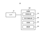
- FIG. 3 is a block diagram showing the functional configuration of the authentication system according to the first embodiment
- the authentication system 10 includes a camera 18 and a processing section 100.
- the processing unit 100 is configured to be able to execute various processes in the authentication system 10 .
- the processing unit 100 includes a target detection unit 110, a switching unit 120, and an authentication unit 130 as components for realizing its functions.
- each of the target detection unit 110, the switching unit 120, and the authentication unit 130 may be a functional block realized by, for example, the above-described processor 11 (see FIG. 1).
- Some or all of the functions of the processing unit 100 described above may be implemented in the camera 18 .
- the switching unit 120 is configured to be able to switch blur photography to normal photography when the object detection unit 110 detects an authentication target.
- the switching unit 120 switches blur photography to normal photography, for example, by controlling the filter switching unit 22 (see FIG. 2) described above.
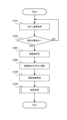
- FIG. 4 is a flow chart showing the operation flow of the authentication system according to the first embodiment.
- the object detection unit 110 acquires a blurred image captured by blurring (step S101). Then, the object detection unit 110 detects the existence of the authentication object based on the obtained blurred image (step S102). Note that if the authentication target is not detected from the blurred image (step S102: NO), the process may start again from step S101.
- step S102 if the authentication target is detected from the blurred image (step S102: YES), the switching unit 120 instructs the filter switching unit 22 to switch the filter, and switches the blur photography to normal photography (step S103). After that, the authentication unit 130 acquires a normal image taken by normal photography (step S104). Then, the authentication unit 130 executes authentication processing for the authentication target based on the obtained normal image (step S105).
- the authentication system 10 may be configured as a system that executes authentication processing at the walkthrough gate.
- the camera 18 here is configured as one included in the face authentication terminal 200 installed at the gate 300 .
- the camera 18 photographs the face of the authentication target 50 who is about to pass through the gate 300 .
- the image captured by the camera 18 is displayed toward the authentication target 50 on the monitor provided in the face authentication terminal 200 .
- the gate 300 is provided with a passage confirmation sensor 305 for confirming that the object 50 has passed through the gate 300 .
- data such as images acquired by the face authentication terminal 200 is configured to be output to the face authentication server storage 400 .
- the camera 18 performs blurred photography in a standby state (that is, a state in which authentication processing is not performed).
- An image captured by blurring photography is an image in which the presence of an authentication target can be detected, but details such as the face of the target cannot be determined. In other words, the privacy of the target is protected.
- the blurred photography is switched to the normal photography, as already described. Therefore, the normal image captured by the camera 18 is clear (that is, an image on which authentication processing can be performed).
- a specific example of the authentication process here that is, the process of step S105 in FIG. 4 described above) will be described below.
- the authentication unit 130 first determines whether or not the authentication target captured in the normal image is the registered target person (step S151). That is, it is determined whether or not the subject of authentication is registered as a user who may pass through the gate 300 . If the person to be authenticated is not the person to be registered (step S151: NO), the image acquired for authentication (that is, the normal image) is discarded (step S157), and the series of operations may be terminated.
- the authentication unit 130 determines whether the object to be authenticated has reached the unlocking position of the gate 300 (step S152). Whether or not the object to be authenticated has reached the unlocked position may be determined, for example, based on the gap between the object to be authenticated in the normal image. If the object to be authenticated has not reached the unlocked position of gate 300 (step S152: NO), it is determined that the object to be authenticated is the object to be registered until a certain period of time has passed (step S153: NO). ), it is repeatedly determined whether or not the object to be authenticated has reached the unlocked position. On the other hand, if a certain period of time has passed since the authentication target was determined to be the registration target (step S153: YES), the image acquired for authentication is discarded (step S157), and the series of operations ends. may be
- step S152 When the authentication target reaches the unlocking position of the gate 300 (step S152: YES), the authentication unit 130 unlocks the gate 300 (step S154). After that, when it is confirmed by the passage confirmation sensor 305 that the object to be authenticated has passed through the gate 300 (step S155: YES), the authentication unit 130 performs the locking process of the gate 300 (step S156). Note that if the object to be authenticated does not pass through the gate 300 even though the unlocking process has been performed (step S155: NO), the authentication unit 130 determines that the object to be authenticated has turned back halfway, for example, and the image acquired for authentication is discarded (step S158), the gate 300 is locked (step S156).
- blurred photography is performed until the presence of the authentication target is detected, and normal photography is performed when the presence of the authentication target is detected.
- a switch is made to In this way, for example, it is possible to suppress execution of normal photography (that is, photography in a non-blurred state) for a user who does not intend to be authenticated. Processing can be executed properly.
- FIG. 8 is a flow chart showing the operation flow of the authentication system according to the second embodiment.
- the same reference numerals are assigned to the same processes as those shown in FIG.
- the target detection unit 110 first acquires a blurred image captured by blurring (step S101). Then, the target detection unit 110 detects a face from the acquired blurred image (step S201).
- the face detection method is not particularly limited, but the detailed position and shape of the face may not be detected. Face detection may be performed by, for example, skeleton detection. If no face is detected from the blurred image (step S201: NO), the process may start again from step S101.
- step S202 if it is determined that the size of the detected face is larger than the predetermined threshold (step S202: YES), the switching unit 120 instructs the filter switching unit 22 to switch the filter, and switches blur photography to normal photography (step S103). After that, the authentication unit 130 acquires a normal image taken by normal photography (step S104). Then, the authentication unit 130 executes authentication processing for the authentication target based on the obtained normal image (step S105).
- FIG. 9 is a flow chart showing the operation flow of the authentication system according to the third embodiment.
- the same reference numerals are assigned to the same processes as those shown in FIG.
- FIG. 11 is a plan view showing an example of a blurred image and a normal image captured by the authentication system according to the fourth embodiment.
- FIG. 12 An authentication system 10 according to the fifth embodiment will be described with reference to FIGS. 12 and 13.
- FIG. 12 It should be noted that the fifth embodiment differs from the above-described fourth embodiment only in a part of the operation, and other parts may be the same as those of the first to fourth embodiments. Therefore, in the following, portions different from the already described embodiments will be described in detail, and descriptions of other overlapping portions will be omitted as appropriate.
- FIG. 12 is a flow chart showing the operation flow of the authentication system according to the fifth embodiment.
- the same reference numerals are given to the same processes as those shown in FIG.
- the target detection unit 110 selects the face area closest to the camera 18 (step S502).
- the face region closest to camera 18 may be determined, for example, based on the size of the face region in the blurred image.
- the switching unit 120 switches only the selected face region from blur photography to normal photography (step S502). In other words, the user's face area other than the head area is left blurred.
- the authentication unit 130 acquires a normal image taken by normal photography (step S104). Then, the authentication unit 130 executes authentication processing for the authentication target based on the obtained normal image (step S105).
- normal photography is switched to blurred photography when the authentication processing for the authentication target is completed.
- the time during which normal photography is performed can be shortened (the time can be limited only to the timing at which authentication processing is performed), so it is possible to more appropriately protect the privacy of users who are not to be authenticated.
- the predetermined action detection unit 150 is configured to be able to detect a predetermined action by an authentication target.
- the predetermined action may be, for example, a preset gesture. Gestures may include utterances, face directions, stepping, etc., in addition to gestures and gestures.
- the predetermined behavior may include suspicious behavior. Suspicious behavior may be, for example, behavior such as staying in a predetermined area all the time, crouching down, or leaving luggage behind.
- the predetermined behavior detection unit 150 may detect the predetermined behavior from the blurred image, or may detect the predetermined behavior using a separate sensor or another camera. For example, the predetermined behavior detection unit 150 may use a pressure sensor to determine whether the target is walking along specific footprints.
- the object detection means detects the moving object in the blurred image, and the moving object is approaching the photographing means for the authentication. 10.
- the authentication system of claim 1 for detecting as a target.
Abstract
This authentication system comprises: a photographing means capable of switching between normal photography and blur photography that involves photographing an image with less clarity than the normal photography; a target detection means that detects (S102) an authentication target on the basis of a blurred image acquired (S101) by the blur photography; a switching means that switches (S103) from the blur photography to the normal photography if the authentication target is detected; and an authentication means that executes processing for authenticating (S105) the authentication target on the basis of a normal image acquired (S104) by the normal photography.
Description
この開示は、認証システム、認証方法、及び記録媒体の技術分野に関する。
This disclosure relates to the technical fields of authentication systems, authentication methods, and recording media.
対象の画像を撮影するシステムにおいては、プライバシーに配慮して画像をぼかす処理が実行されることがある。例えば特許文献1では、監視対象者の接近度合いに応じてぼかし度合いを変化させる技術が開示されている。特許文献2では、主被写体以外の背景領域にぼかし処理を行うが、認証処理の期間についてはぼかし処理を解除する技術が開示されている。特許文献3では、検出した人物の属性に基づいてぼかし強度を決定する技術が開示されている。
In the system that captures the target image, processing to blur the image may be performed in consideration of privacy. For example, Patent Literature 1 discloses a technique for changing the degree of blurring according to the degree of proximity of a person to be monitored. Japanese Patent Application Laid-Open No. 2002-200000 discloses a technique in which a background area other than a main subject is subjected to blurring processing, but the blurring processing is canceled during the period of authentication processing. Japanese Patent Application Laid-Open No. 2002-200002 discloses a technique for determining the blur intensity based on the detected attributes of a person.
この開示は、先行技術文献に開示された技術を改善することを目的とする。
The purpose of this disclosure is to improve the technology disclosed in prior art documents.
この開示の認証システムの一の態様は、通常撮影と、前記通常撮影より鮮明度が低い状態で撮影するぼかし撮影とを切替可能な撮影手段と、前記ぼかし撮影で取得したぼかし画像に基づいて、認証対象を検出する対象検出手段と、前記認証対象が検出された場合に、前記ぼかし撮影から前記通常撮影への切り替えを行う切替手段と、前記通常撮影で取得した通常画像に基づいて、前記認証対象の認証処理を実行する認証手段と、を備える。
One aspect of the authentication system of this disclosure is based on a photographing means capable of switching between normal photography and blurred photography in which the definition is lower than that of the normal photography, and the blurred image obtained by the blurry photography, a target detecting means for detecting an authentication target; a switching means for switching from the blurred shooting to the normal shooting when the authentication target is detected; and authentication means for executing a target authentication process.
この開示の認証方法の一の態様は、通常撮影と、前記通常撮影より鮮明度が低い状態で撮影するぼかし撮影とを切替可能な撮影手段を用いる認証方法であって、前記ぼかし撮影で取得したぼかし画像に基づいて、認証対象を検出し、前記認証対象が検出された場合に、前記ぼかし撮影から前記通常撮影への切り替えを行い、前記通常撮影で取得した通常画像に基づいて、前記認証対象の認証処理を実行する。
One aspect of the authentication method of the present disclosure is an authentication method using a photographing means capable of switching between normal photography and blurred photography in which the sharpness is lower than that of the normal photography, wherein An authentication target is detected based on the blurred image, and when the authentication target is detected, switching from the blur photography to the normal photography is performed, and the authentication target is detected based on the normal image obtained by the normal photography. authentication process.
この開示の記録媒体の一の態様は、通常撮影と、前記通常撮影より鮮明度が低い状態で撮影するぼかし撮影とを切替可能な撮影手段を用いる認証方法であって、前記ぼかし撮影で取得したぼかし画像に基づいて、認証対象を検出し、前記認証対象が検出された場合に、前記ぼかし撮影から前記通常撮影への切り替えを行い、前記通常撮影で取得した通常画像に基づいて、前記認証対象の認証処理を実行する、認証方法を少なくとも1つのコンピュータに実行させるコンピュータプログラムが記録されている。
One aspect of the recording medium of this disclosure is an authentication method using a photographing unit capable of switching between normal photography and blurred photography in which the image is captured with a lower definition than the normal photography, wherein An authentication target is detected based on the blurred image, and when the authentication target is detected, switching from the blur photography to the normal photography is performed, and the authentication target is detected based on the normal image obtained by the normal photography. A computer program is recorded for causing at least one computer to perform an authentication method for performing the authentication process of the.
以下、図面を参照しながら、認証システム、認証方法、及び記録媒体の実施形態について説明する。
Embodiments of an authentication system, an authentication method, and a recording medium will be described below with reference to the drawings.
<第1実施形態>
第1実施形態に係る認証システムについて、図1から図7を参照して説明する。 <First Embodiment>
An authentication system according to the first embodiment will be described with reference to FIGS. 1 to 7. FIG.
第1実施形態に係る認証システムについて、図1から図7を参照して説明する。 <First Embodiment>
An authentication system according to the first embodiment will be described with reference to FIGS. 1 to 7. FIG.
(ハードウェア構成)
まず、図1を参照しながら、第1実施形態に係る認証システムのハードウェア構成について説明する。図1は、第1実施形態に係る認証システムのハードウェア構成を示すブロック図である。 (Hardware configuration)
First, the hardware configuration of the authentication system according to the first embodiment will be described with reference to FIG. FIG. 1 is a block diagram showing the hardware configuration of an authentication system according to the first embodiment.
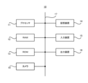
図1に示すように、第1実施形態に係る認証システム10は、プロセッサ11と、RAM(Random Access Memory)12と、ROM(Read Only Memory)13と、記憶装置14とを備えている。認証システム10は更に、入力装置15と、出力装置16と、を備えていてもよい。上述したプロセッサ11と、RAM12と、ROM13と、記憶装置14と、入力装置15と、出力装置16とは、データバス17を介して接続されている。
As shown in FIG. 1, the authentication system 10 according to the first embodiment includes a processor 11, a RAM (Random Access Memory) 12, a ROM (Read Only Memory) 13, and a storage device 14. Authentication system 10 may further comprise an input device 15 and an output device 16 . The processor 11 , RAM 12 , ROM 13 , storage device 14 , input device 15 and output device 16 are connected via a data bus 17 .
プロセッサ11は、コンピュータプログラムを読み込む。例えば、プロセッサ11は、RAM12、ROM13及び記憶装置14のうちの少なくとも一つが記憶しているコンピュータプログラムを読み込むように構成されている。或いは、プロセッサ11は、コンピュータで読み取り可能な記録媒体が記憶しているコンピュータプログラムを、図示しない記録媒体読み取り装置を用いて読み込んでもよい。プロセッサ11は、ネットワークインタフェースを介して、認証システム10の外部に配置される不図示の装置からコンピュータプログラムを取得してもよい(つまり、読み込んでもよい)。プロセッサ11は、読み込んだコンピュータプログラムを実行することで、RAM12、記憶装置14、入力装置15及び出力装置16を制御する。本実施形態では特に、プロセッサ11が読み込んだコンピュータプログラムを実行すると、プロセッサ11内には、対象を撮像して認証処理を実行するための機能ブロックが実現される。即ち、プロセッサ11は、認証システム10における各制御を実行するコントローラとして機能してよい。
The processor 11 reads a computer program. For example, processor 11 is configured to read a computer program stored in at least one of RAM 12, ROM 13 and storage device . Alternatively, the processor 11 may read a computer program stored in a computer-readable recording medium using a recording medium reader (not shown). The processor 11 may acquire (that is, read) a computer program from a device (not shown) arranged outside the authentication system 10 via the network interface. The processor 11 controls the RAM 12, the storage device 14, the input device 15 and the output device 16 by executing the read computer program. Particularly in this embodiment, when the computer program read by the processor 11 is executed, the processor 11 implements functional blocks for capturing an image of an object and executing authentication processing. That is, the processor 11 may function as a controller that executes each control in the authentication system 10 .
プロセッサ11は、例えばCPU(Central Processing Unit)、GPU(Graphics Processing Unit)、FPGA(field-programmable gate array)、DSP(Demand-Side Platform)、ASIC(Application Specific Integrated Circuit)として構成されてよい。プロセッサ11は、これらのうち一つで構成されてもよいし、複数を並列で用いるように構成されてもよい。
The processor 11 includes, for example, a CPU (Central Processing Unit), GPU (Graphics Processing Unit), FPGA (Field-Programmable Gate Array), DSP (Demand-Side Platform), ASIC (Application Specific Integral ted circuit). The processor 11 may be configured with one of these, or may be configured to use a plurality of them in parallel.
RAM12は、プロセッサ11が実行するコンピュータプログラムを一時的に記憶する。RAM12は、プロセッサ11がコンピュータプログラムを実行している際にプロセッサ11が一時的に使用するデータを一時的に記憶する。RAM12は、例えば、D-RAM(Dynamic Random Access Memory)や、SRAM(Static Random Access Memory)であってよい。また、RAM12に代えて、他の種類の揮発性メモリが用いられてもよい。
The RAM 12 temporarily stores computer programs executed by the processor 11. The RAM 12 temporarily stores data temporarily used by the processor 11 while the processor 11 is executing the computer program. The RAM 12 may be, for example, a D-RAM (Dynamic Random Access Memory) or an SRAM (Static Random Access Memory). Also, instead of the RAM 12, other types of volatile memory may be used.
ROM13は、プロセッサ11が実行するコンピュータプログラムを記憶する。ROM13は、その他に固定的なデータを記憶していてもよい。ROM13は、例えば、P-ROM(Programmable Read Only Memory)や、EPROM(Erasable Read Only Memory)であってよい。また、ROM13に代えて、他の種類の不揮発性 メモリが用いられてもよい。
The ROM 13 stores computer programs executed by the processor 11 . The ROM 13 may also store other fixed data. The ROM 13 may be, for example, a P-ROM (Programmable Read Only Memory) or an EPROM (Erasable Read Only Memory). Also, instead of the ROM 13, other types of non-volatile memory may be used.
記憶装置14は、認証システム10が長期的に保存するデータを記憶する。記憶装置14は、プロセッサ11の一時記憶装置として動作してもよい。記憶装置14は、例えば、ハードディスク装置、光磁気ディスク装置、SSD(Solid State Drive)及びディスクアレイ装置のうちの少なくとも一つを含んでいてもよい。
The storage device 14 stores data that the authentication system 10 saves for a long time. Storage device 14 may act as a temporary storage device for processor 11 . The storage device 14 may include, for example, at least one of a hard disk device, a magneto-optical disk device, an SSD (Solid State Drive), and a disk array device.
入力装置15は、認証システム10のユーザからの入力指示を受け取る装置である。入力装置15は、例えば、キーボード、マウス及びタッチパネルのうちの少なくとも一つを含んでいてもよい。入力装置15は、スマートフォンやタブレット等の携帯端末として構成されていてもよい。入力装置15は、例えばマイクを含む音声入力が可能な装置であってもよい。
The input device 15 is a device that receives input instructions from the user of the authentication system 10 . Input device 15 may include, for example, at least one of a keyboard, mouse, and touch panel. The input device 15 may be configured as a mobile terminal such as a smart phone or a tablet. The input device 15 may be a device capable of voice input including, for example, a microphone.
出力装置16は、認証システム10に関する情報を外部に対して出力する装置である。例えば、出力装置16は、認証システム10に関する情報を表示可能な表示装置(例えば、ディスプレイ)であってもよい。また、出力装置16は、認証システム10に関する情報を音声出力可能なスピーカ等であってもよい。出力装置16は、スマートフォンやタブレット等の携帯端末として構成されていてもよい。また、出力装置16は、画像以外の形式で情報を出力する装置であってもよい。例えば、出力装置16は、認証システム10に関する情報を音声で出力するスピーカであってもよい。
The output device 16 is a device that outputs information about the authentication system 10 to the outside. For example, output device 16 may be a display device (eg, display) capable of displaying information about authentication system 10 . Also, the output device 16 may be a speaker or the like capable of outputting information about the authentication system 10 by voice. The output device 16 may be configured as a mobile terminal such as a smart phone or a tablet. Also, the output device 16 may be a device that outputs information in a format other than an image. For example, the output device 16 may be a speaker that outputs information about the authentication system 10 by voice.
カメラ18は、認証システム10の認証対象を撮影するために設けられている。即ち、カメラは、対象の認証処理に用いる画像(例えば、対象の顔画像など)を撮影可能に構成されている。カメラ18の種類は特に限定されるものではなく、例えば可視光カメラであってもよいし、近赤外線カメラであってもよい。カメラ18のより具体的な構成例については、後に詳しく説明する。
The camera 18 is provided to photograph the authentication target of the authentication system 10. That is, the camera is configured to be able to capture an image (for example, a face image of the target) used for authentication processing of the target. The type of camera 18 is not particularly limited, and may be, for example, a visible light camera or a near-infrared camera. A more specific configuration example of the camera 18 will be described in detail later.
なお、図1で説明したハードウェアのうち、一部のハードウェアは認証システム10以外の装置が備えていてもよい。例えば、認証システム10は、上述したプロセッサ11、RAM12、ROM13のみを備えて構成され、その他の構成要素(即ち、記憶装置14、入力装置15、出力装置16)については、例えば認証システム10に接続される外部の装置が備えるようにしてもよい。また、認証システムは10、一部の演算機能を外部の装置(例えば、外部サーバやクラウド等)によって実現するものであってもよい。
Of the hardware described in FIG. 1, some of the hardware may be provided in devices other than the authentication system 10. For example, the authentication system 10 includes only the processor 11, the RAM 12, and the ROM 13 described above, and the other components (that is, the storage device 14, the input device 15, and the output device 16) are connected to the authentication system 10, for example. It may be provided in an external device to be used. In addition, the authentication system 10 may be one in which a part of the calculation functions is realized by an external device (for example, an external server, a cloud, etc.).
(カメラの構成例)
次に、図2を参照しながら、上述したカメラ18の具体的な構成例について説明する。図2は、第1実施形態に係る認証システムが備えるカメラの具体的な構成を示すブロック図である。 (Camera configuration example)
Next, a specific configuration example of thecamera 18 described above will be described with reference to FIG. FIG. 2 is a block diagram showing a specific configuration of a camera included in the authentication system according to the first embodiment.
次に、図2を参照しながら、上述したカメラ18の具体的な構成例について説明する。図2は、第1実施形態に係る認証システムが備えるカメラの具体的な構成を示すブロック図である。 (Camera configuration example)
Next, a specific configuration example of the
図2に示すように、第1実施形態に係るカメラ18は、その主な構成要素として、レンズ21と、フィルタ切替部22と、イメージセンサ23と、画像処理部24と、出力部25と、を備えて構成されてよい。カメラ18で撮像する際、レンズ21に入射した光は、フィルタ切替部22(正確には、フィルタ切替部が備えるフィルタ)を介して、イメージセンサ23で結像される。そして、画像処理部24は、イメージセンサの出力に対して各種画像処理を実行し、出力部25によって画像データが出力される。
As shown in FIG. 2, the camera 18 according to the first embodiment includes, as its main components, a lens 21, a filter switching unit 22, an image sensor 23, an image processing unit 24, an output unit 25, may be configured with When the camera 18 takes an image, the light incident on the lens 21 forms an image on the image sensor 23 via the filter switching section 22 (more precisely, the filter included in the filter switching section). The image processing unit 24 performs various image processing on the output of the image sensor, and the output unit 25 outputs image data.
上述したフィルタ切替部22は、ぼかしフィルタと通常フィルタとを備えており、それらを切り替えることで撮像モードを切替可能に構成されている。具体的には、フィルタ切替部22によってぼかしフィルタが使用される状態に切り替えられると、カメラ18では、ぼかし撮影(即ち、鮮明度の低いぼかした状態での撮影)が行われることになる。一方、フィルタ切替部22によって通常フィルタが使用される状態に切り替えられると、カメラ18では、通常撮影(即ち、鮮明度の高いぼかさない状態での撮影)が行われることになる。なお、ここでの「ぼかし撮影」は、撮影される認証対象のプライバシーが守られる程度に鮮明度が低い状態での撮影であればよい。フィルタ切替部22は、上述したように種類の異なるフィルタを切り替えることで、通常撮影とぼかし撮影とを切り替えてもよいし、液晶等によって構成されるフィルタを用いて電気的に光を透過する状態と半透過すると状態とを切り替えることで、通常撮影とぼかし撮影とを切り替えてもよい。
The filter switching unit 22 described above includes a blurring filter and a normal filter, and is configured to be able to switch between imaging modes by switching between them. Specifically, when the filter switching unit 22 switches to a state in which the blurring filter is used, the camera 18 performs blurred photography (that is, photography in a blurred state with low definition). On the other hand, when the filter switching unit 22 switches to the state where the normal filter is used, the camera 18 performs normal photography (that is, photography with high definition and no blurring). It should be noted that the “blurring photography” here may be photography in a state where the definition is low enough to protect the privacy of the subject to be photographed. The filter switching unit 22 may switch between normal shooting and blurred shooting by switching different types of filters as described above, or may switch between normal shooting and blurred shooting by switching between different types of filters as described above. By switching between , and semi-transmissive state, normal photography and blurred photography may be switched.
上述した構成はあくまで一例であり、カメラ18は異なる要素を備えて構成されてよい。特に、カメラ18は、フィルタ切替部22とは異なる要素を用いて通常撮影とぼかし撮影を実現可能とされてよい。つまり、通常撮影とぼかし撮影とを切替可能とする構成については、フィルタを用いる構成に限定されるものではない。例えば、カメラ18は、ピントを対象に合わせた状態で撮影することで通常撮影を行い、ピントをあえて対象からはずした状態で撮影することでぼかし撮影を行ってもよい。或いは、カメラ18は、露出やシャッタースピードを適正な値に調整することで通常撮影を行い、露出やシャッタースピードをあえて適正な値から外すことでぼかし撮影を行ってもよい。或いは、カメラ18は、意図的に画像を粗くする(例えば、解像度を低くする)ことでぼかし撮影を行ってもよい。
The configuration described above is merely an example, and the camera 18 may be configured with different elements. In particular, the camera 18 may be capable of performing normal photography and blurred photography using elements different from those of the filter switching unit 22 . In other words, the configuration that enables switching between normal shooting and blurred shooting is not limited to a configuration using a filter. For example, the camera 18 may perform normal photography by photographing with the object in focus, and blur photography by photographing with the object intentionally out of focus. Alternatively, the camera 18 may perform normal photography by adjusting the exposure and shutter speed to appropriate values, and may perform blurred photography by intentionally removing the exposure and shutter speed from the appropriate values. Alternatively, the camera 18 may intentionally roughen the image (for example, lower the resolution) to perform blurred photography.
(機能的構成)
次に、図3を参照しながら、第1実施形態に係る認証システム10の機能的構成について説明する。図3は、第1実施形態に係る認証システムの機能的構成を示すブロック図である。 (Functional configuration)
Next, the functional configuration of theauthentication system 10 according to the first embodiment will be described with reference to FIG. FIG. 3 is a block diagram showing the functional configuration of the authentication system according to the first embodiment;
次に、図3を参照しながら、第1実施形態に係る認証システム10の機能的構成について説明する。図3は、第1実施形態に係る認証システムの機能的構成を示すブロック図である。 (Functional configuration)
Next, the functional configuration of the
図3に示すように、第1実施形態に係る認証システム10は、カメラ18と、処理部100と、を備えて構成されている。処理部100は、認証システム10における各種処理を実行可能に構成されている。処理部100は、その機能を実現するための構成要素として、対象検出部110と、切替部120と、認証部130と、を備えている。なお、対象検出部110、切替部120、及び認証部130の各々は、例えば上述したプロセッサ11(図1参照)によって実現される機能ブロックであってよい。上述した処理部100の一部又は全部の機能は、カメラ18に実装されるものであってもよい。
As shown in FIG. 3, the authentication system 10 according to the first embodiment includes a camera 18 and a processing section 100. As shown in FIG. The processing unit 100 is configured to be able to execute various processes in the authentication system 10 . The processing unit 100 includes a target detection unit 110, a switching unit 120, and an authentication unit 130 as components for realizing its functions. Note that each of the target detection unit 110, the switching unit 120, and the authentication unit 130 may be a functional block realized by, for example, the above-described processor 11 (see FIG. 1). Some or all of the functions of the processing unit 100 described above may be implemented in the camera 18 .
対象検出部110は、ぼかし撮影によって撮影されたぼかし画像に基づいて、認証対象(即ち、認証処理を実行すべき対象)の存在を検出可能に構成されている。認証対象の具体的な検出手法は特に限定されるものではない。検出手法の具体例については、後述する他の実施形態において詳しく説明する。
The target detection unit 110 is configured to be able to detect the existence of an authentication target (that is, a target for which authentication processing should be performed) based on a blurred image captured by blurring photography. A specific method for detecting an authentication target is not particularly limited. A specific example of the detection method will be described in detail in another embodiment described later.
切替部120は、対象検出部110で認証対象が検出された場合に、ぼかし撮影を通常撮影に切替可能に構成されている。切替部120は、例えば上述したフィルタ切替部22(図2参照)を制御することで、ぼかし撮影を通常撮影に切り替える。
The switching unit 120 is configured to be able to switch blur photography to normal photography when the object detection unit 110 detects an authentication target. The switching unit 120 switches blur photography to normal photography, for example, by controlling the filter switching unit 22 (see FIG. 2) described above.
認証部130は、切替部120によってぼかし撮影が通常撮影に切り替えられた後、通常撮影で取得された通常画像に基づいて、認証対象の認証処理を実行する。ここでの認証処理は、典型的には顔認証であるが、画像を用いる他の認証(例えば、虹彩認証等)であってもよい。なお、認証処理の具体的な手法については、既存の技術を適宜適用することができるため、ここでの詳細な説明は省略する。認証部130は、認証結果を出力する機能を有していてもよい。また、認証部130は、認証結果に応じて各種制御(例えば、ゲートの開閉)を実行可能に構成されてもよい。
After the switching unit 120 switches the blurred photography to the normal photography, the authentication unit 130 performs authentication processing for the authentication target based on the normal image acquired by the normal photography. The authentication processing here is typically face authentication, but may be other authentication using an image (eg, iris authentication, etc.). Note that existing techniques can be appropriately applied to a specific method of the authentication process, so a detailed description thereof will be omitted here. The authentication unit 130 may have a function of outputting the authentication result. Further, the authentication unit 130 may be configured to be able to execute various controls (for example, opening and closing a gate) according to the authentication result.
(動作の流れ)
次に、図4を参照しながら、第1実施形態に係る認証システム10の動作の流れについて説明する。図4は、第1実施形態に係る認証システムの動作の流れを示すフローチャートである。 (Flow of operation)
Next, the operation flow of theauthentication system 10 according to the first embodiment will be described with reference to FIG. FIG. 4 is a flow chart showing the operation flow of the authentication system according to the first embodiment.
次に、図4を参照しながら、第1実施形態に係る認証システム10の動作の流れについて説明する。図4は、第1実施形態に係る認証システムの動作の流れを示すフローチャートである。 (Flow of operation)
Next, the operation flow of the
図4に示すように、第1実施形態に係る認証システム10による動作が開始されると、まず対象検出部110が、ぼかし撮影によって撮影されたぼかし画像を取得する(ステップS101)。そして、対象検出部110は、取得したぼかし画像に基づいて、認証対象の存在を検出する(ステップS102)。なお、ぼかし画像から認証対象が検出されていない場合(ステップS102:NO)、再びステップS101から処理を開始してよい。
As shown in FIG. 4, when the operation of the authentication system 10 according to the first embodiment is started, first, the object detection unit 110 acquires a blurred image captured by blurring (step S101). Then, the object detection unit 110 detects the existence of the authentication object based on the obtained blurred image (step S102). Note that if the authentication target is not detected from the blurred image (step S102: NO), the process may start again from step S101.
一方、ぼかし画像から認証対象が検出されている場合(ステップS102:YES)、切替部120がフィルタ切替部22にフィルタの切替を指示し、ぼかし撮影を通常撮影へと切り替える(ステップS103)。その後、認証部130は、通常撮影によって撮影された通常画像を取得する(ステップS104)。そして、認証部130は、取得した通常画像に基づいて、認証対象の認証処理を実行する(ステップS105)。
On the other hand, if the authentication target is detected from the blurred image (step S102: YES), the switching unit 120 instructs the filter switching unit 22 to switch the filter, and switches the blur photography to normal photography (step S103). After that, the authentication unit 130 acquires a normal image taken by normal photography (step S104). Then, the authentication unit 130 executes authentication processing for the authentication target based on the obtained normal image (step S105).
(具体的な適用例)
次に、図5から図7を参照しながら、第1実施形態に係る認証システム10の具体的な適用例について説明する。図5は、第1実施形態に係る認証システムによる具体的な適用例を示す側面図である。図6は、第1実施形態に係る認証システムで撮像されるぼかし画像及び通常画像の一例を示す平面図である。図7は、第1実施形態に係る認証システムによる認証処理の流れの一例を示すフローチャートである。 (Specific application example)
Next, specific application examples of theauthentication system 10 according to the first embodiment will be described with reference to FIGS. 5 to 7. FIG. FIG. 5 is a side view showing a specific application example of the authentication system according to the first embodiment. FIG. 6 is a plan view showing an example of a blurred image and a normal image captured by the authentication system according to the first embodiment. FIG. 7 is a flow chart showing an example of the flow of authentication processing by the authentication system according to the first embodiment.
次に、図5から図7を参照しながら、第1実施形態に係る認証システム10の具体的な適用例について説明する。図5は、第1実施形態に係る認証システムによる具体的な適用例を示す側面図である。図6は、第1実施形態に係る認証システムで撮像されるぼかし画像及び通常画像の一例を示す平面図である。図7は、第1実施形態に係る認証システムによる認証処理の流れの一例を示すフローチャートである。 (Specific application example)
Next, specific application examples of the
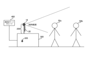
図5に示すように、第1実施形態に係る認証システム10は、ウォークスルーゲートにおける認証処理を実行するシステムとして構成されてよい。ここでのカメラ18は、ゲート300に設置された顔認証端末200が備えるものとして構成されている。この場合、カメラ18は、ゲート300を通過しようとする認証対象50の顔を撮影する。なお、カメラ18で撮影される画像は、顔認証端末200が備えるモニタにより認証対象50に向けて表示される。ゲート300には、対象50がゲート300を通過したことを確認するための通過確認センサ305が設けられている。また、顔認証端末200で取得された画像等のデータは、顔認証サーバストレージ400に出力される構成となっている。
As shown in FIG. 5, the authentication system 10 according to the first embodiment may be configured as a system that executes authentication processing at the walkthrough gate. The camera 18 here is configured as one included in the face authentication terminal 200 installed at the gate 300 . In this case, the camera 18 photographs the face of the authentication target 50 who is about to pass through the gate 300 . Note that the image captured by the camera 18 is displayed toward the authentication target 50 on the monitor provided in the face authentication terminal 200 . The gate 300 is provided with a passage confirmation sensor 305 for confirming that the object 50 has passed through the gate 300 . Also, data such as images acquired by the face authentication terminal 200 is configured to be output to the face authentication server storage 400 .
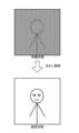
図6に示すように、カメラ18は、待機状態(即ち、認証処理を実行していない状態)では、ぼかし撮影を行う。ぼかし撮影で撮影される画像は、認証対象の存在が検出できる程度の画像ではあるものの、対象の顔等の詳細については判別できない状態である。言い換えれば、対象のプライバシーが守られた状態である。一方で、認証対象の存在が検出されて認証状態(即ち、認証処理を実行する状態)となると、すでに説明したように、ぼかし撮影が通常撮影に切り替えられる。このため、カメラ18で撮影される通常画像は鮮明なもの(即ち、認証処理が実行可能な画像)となる。以下では、ここでの認証処理(即ち、上述した図4のステップS105の処理)の具体例について説明する。
As shown in FIG. 6, the camera 18 performs blurred photography in a standby state (that is, a state in which authentication processing is not performed). An image captured by blurring photography is an image in which the presence of an authentication target can be detected, but details such as the face of the target cannot be determined. In other words, the privacy of the target is protected. On the other hand, when the existence of the authentication target is detected and the authentication state (that is, the state in which the authentication process is executed) occurs, the blurred photography is switched to the normal photography, as already described. Therefore, the normal image captured by the camera 18 is clear (that is, an image on which authentication processing can be performed). A specific example of the authentication process here (that is, the process of step S105 in FIG. 4 described above) will be described below.
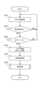
図7に示すように、認証処理が開始されると、認証部130は、まず通常画像で撮像された認証対象が登録対象者であるか否かを判定する(ステップS151)。即ち、認証対象が、ゲート300を通過してもよいユーザとして登録されているか否かを判定する。なお、認証対象が登録対象者でない場合(ステップS151:NO)、認証用に取得した画像(即ち、通常画像)が破棄された上で(ステップS157)、一連の動作が終了されてよい。
As shown in FIG. 7, when the authentication process is started, the authentication unit 130 first determines whether or not the authentication target captured in the normal image is the registered target person (step S151). That is, it is determined whether or not the subject of authentication is registered as a user who may pass through the gate 300 . If the person to be authenticated is not the person to be registered (step S151: NO), the image acquired for authentication (that is, the normal image) is discarded (step S157), and the series of operations may be terminated.
認証対象が登録対象者である場合(ステップS151:YES)、認証部130は、認証対象がゲート300の開錠位置に到達したか否かを判定する(ステップS152)。なお、認証対象が開錠位置に到達したか否かは、例えば通常画像における認証対象の目間に基づいて判定されてよい。なお、認証対象がゲート300の開錠位置に到達していない場合(ステップS152:NO)、認証対象が登録対象であると判定されてから一定時間が経過していない間は(ステップS153:NO)、認証対象が開錠位置に到達したか否かが繰り返し判定されることになる。一方で、認証対象が登録対象であると判定されてから一定時間が経過した場合(ステップS153:YES)、認証用に取得した画像が破棄された上で(ステップS157)、一連の動作が終了されてよい。
If the object to be authenticated is the person to be registered (step S151: YES), the authentication unit 130 determines whether the object to be authenticated has reached the unlocking position of the gate 300 (step S152). Whether or not the object to be authenticated has reached the unlocked position may be determined, for example, based on the gap between the object to be authenticated in the normal image. If the object to be authenticated has not reached the unlocked position of gate 300 (step S152: NO), it is determined that the object to be authenticated is the object to be registered until a certain period of time has passed (step S153: NO). ), it is repeatedly determined whether or not the object to be authenticated has reached the unlocked position. On the other hand, if a certain period of time has passed since the authentication target was determined to be the registration target (step S153: YES), the image acquired for authentication is discarded (step S157), and the series of operations ends. may be
認証対象がゲート300の開錠位置に到達した場合(ステップS152:YES)、認証部130は、ゲート300の開錠処理を行う(ステップS154)。その後、通過確認センサ305によって認証対象がゲート300を通過したことが確認されると(ステップS155:YES)、認証部130は、ゲート300の閉錠処理を行う(ステップS156)。なお、開錠処理をしたにもかかわらず、認証対象がゲート300を通過しない場合(ステップS155:NO)、認証部130は、例えば認証対象が途中で引き返したと判断し、認証用に取得した画像を破棄した上で(ステップS158)、ゲート300の閉錠処理を行う(ステップS156)。
When the authentication target reaches the unlocking position of the gate 300 (step S152: YES), the authentication unit 130 unlocks the gate 300 (step S154). After that, when it is confirmed by the passage confirmation sensor 305 that the object to be authenticated has passed through the gate 300 (step S155: YES), the authentication unit 130 performs the locking process of the gate 300 (step S156). Note that if the object to be authenticated does not pass through the gate 300 even though the unlocking process has been performed (step S155: NO), the authentication unit 130 determines that the object to be authenticated has turned back halfway, for example, and the image acquired for authentication is discarded (step S158), the gate 300 is locked (step S156).
(技術的効果)
次に、第1実施形態に係る認証システム10によって得られる技術的効果について説明する。 (technical effect)
Next, technical effects obtained by theauthentication system 10 according to the first embodiment will be described.
次に、第1実施形態に係る認証システム10によって得られる技術的効果について説明する。 (technical effect)
Next, technical effects obtained by the
図1から図7で説明したように、第1実施形態に係る認証システム10では、認証対象の存在が検出されるまではぼかし撮影が行われ、認証対象の存在が検出された場合に通常撮影への切り替えが行われる。このようにすれば、例えば認証される意図のないユーザに対する通常撮影(即ち、ぼかさない状態での撮影)が実行されることを抑制できるため、各ユーザのプライバシーに配慮しつつ、認証対象に対する認証処理を適切に実行することができる。
As described with reference to FIGS. 1 to 7, in the authentication system 10 according to the first embodiment, blurred photography is performed until the presence of the authentication target is detected, and normal photography is performed when the presence of the authentication target is detected. A switch is made to In this way, for example, it is possible to suppress execution of normal photography (that is, photography in a non-blurred state) for a user who does not intend to be authenticated. Processing can be executed properly.
<第2実施形態>
第2実施形態に係る認証システム10について、図8を参照して説明する。なお、第2実施形態は、上述した第1実施形態と一部の動作が異なるのみであり、その他の部分については第1実施形態と同一であってよい。このため、以下では、すでに説明した第1実施形態と異なる部分について詳細に説明し、その他の重複する部分については適宜説明を省略するものとする。 <Second embodiment>
Anauthentication system 10 according to the second embodiment will be described with reference to FIG. It should be noted that the second embodiment may differ from the above-described first embodiment only in part of the operation, and other parts may be the same as those of the first embodiment. Therefore, in the following, portions different from the already described first embodiment will be described in detail, and descriptions of other overlapping portions will be omitted as appropriate.
第2実施形態に係る認証システム10について、図8を参照して説明する。なお、第2実施形態は、上述した第1実施形態と一部の動作が異なるのみであり、その他の部分については第1実施形態と同一であってよい。このため、以下では、すでに説明した第1実施形態と異なる部分について詳細に説明し、その他の重複する部分については適宜説明を省略するものとする。 <Second embodiment>
An
(動作の流れ)
まず、図8を参照しながら、第2実施形態に係る認証システム10の動作の流れについて説明する。図8は、第2実施形態に係る認証システムによる動作の流れを示すフローチャートである。なお、図8では、図4で示した処理と同様の処理に同一の符号を付している。 (Flow of operation)
First, the operation flow of theauthentication system 10 according to the second embodiment will be described with reference to FIG. FIG. 8 is a flow chart showing the operation flow of the authentication system according to the second embodiment. In FIG. 8, the same reference numerals are assigned to the same processes as those shown in FIG.
まず、図8を参照しながら、第2実施形態に係る認証システム10の動作の流れについて説明する。図8は、第2実施形態に係る認証システムによる動作の流れを示すフローチャートである。なお、図8では、図4で示した処理と同様の処理に同一の符号を付している。 (Flow of operation)
First, the operation flow of the
図8に示すように、第2実施形態に係る認証システム10による動作が開始されると、まず対象検出部110が、ぼかし撮影によって撮影されたぼかし画像を取得する(ステップS101)。そして、対象検出部110は、取得したぼかし画像から顔を検出する(ステップS201)。ここで顔の検出手法は特に限定されないが、顔の詳細な位置や形状までが検出されずともよい。顔の検出は、例えば骨格検出によって行われてもよい。ぼかし画像から顔が検出されていない場合(ステップS201:NO)、再びステップS101から処理を開始してよい。
As shown in FIG. 8, when the operation of the authentication system 10 according to the second embodiment is started, the target detection unit 110 first acquires a blurred image captured by blurring (step S101). Then, the target detection unit 110 detects a face from the acquired blurred image (step S201). Here, the face detection method is not particularly limited, but the detailed position and shape of the face may not be detected. Face detection may be performed by, for example, skeleton detection. If no face is detected from the blurred image (step S201: NO), the process may start again from step S101.
一方、ぼかし画像から顔が検出されている場合(ステップS201:YES)、対象検出部110は更に、検出した顔の大きさが所定閾値より大きいか否かを判定する(ステップS202)。顔の大きさは、ぼかし画像から判定すればよい。なお、ここでの「所定閾値」は、顔が検出されているユーザが、認証される意図を持ってカメラ18に近づいているかを判定するための閾値として設定されている。例えば、顔の大きさが所定閾値より大きい場合は、明らかにカメラ18に対して接近しているため、認証される意図を持ったユーザである(即ち、認証対象である)と判定できる。一方で、顔の大きさが所定閾値より小さい場合は、例えばカメラの近くを通りかかっただけで認証される意図を持ったユーザとは言えない(即ち、現時点では認証対象ではない)と判定できる。検出した顔の大きさが所定閾値より小さいと判定された場合(ステップS202:NO)、再びステップS101から処理を開始してよい。
On the other hand, if a face has been detected from the blurred image (step S201: YES), the object detection unit 110 further determines whether the size of the detected face is larger than a predetermined threshold (step S202). The size of the face can be determined from the blurred image. The "predetermined threshold" here is set as a threshold for determining whether the user whose face has been detected is approaching the camera 18 with the intention of being authenticated. For example, if the size of the face is larger than a predetermined threshold, it is clearly close to the camera 18, so it can be determined that the user intends to be authenticated (that is, the user is to be authenticated). On the other hand, if the size of the face is smaller than the predetermined threshold, it can be determined that the user is not intended to be authenticated just by passing by the camera (that is, not to be authenticated at present). If it is determined that the size of the detected face is smaller than the predetermined threshold (step S202: NO), the process may start again from step S101.
一方、検出した顔の大きさが所定閾値より大きいと判定された場合(ステップS202:YES)、切替部120がフィルタ切替部22にフィルタの切替を指示し、ぼかし撮影を通常撮影へと切り替える(ステップS103)。その後、認証部130は、通常撮影によって撮影された通常画像を取得する(ステップS104)。そして、認証部130は、取得した通常画像に基づいて、認証対象の認証処理を実行する(ステップS105)。
On the other hand, if it is determined that the size of the detected face is larger than the predetermined threshold (step S202: YES), the switching unit 120 instructs the filter switching unit 22 to switch the filter, and switches blur photography to normal photography ( step S103). After that, the authentication unit 130 acquires a normal image taken by normal photography (step S104). Then, the authentication unit 130 executes authentication processing for the authentication target based on the obtained normal image (step S105).
(技術的効果)
次に、第2実施形態に係る認証システム10によって得られる技術的効果について説明する。 (technical effect)
Next, technical effects obtained by theauthentication system 10 according to the second embodiment will be described.
次に、第2実施形態に係る認証システム10によって得られる技術的効果について説明する。 (technical effect)
Next, technical effects obtained by the
図8で説明したように、第2実施形態に係る認証システム10では、ぼかし画像から顔が検出され、検出された顔の大きさに基づいてぼかし撮影が通常撮影に切り替えられる。このようにすれば、認証される意図のないユーザに対して通常撮影が実行されることを抑制できるため、各ユーザのプライバシーに配慮しつつ、認証対象に対する認証処理を適切に実行することができる。
As described with reference to FIG. 8, in the authentication system 10 according to the second embodiment, a face is detected from a blurred image, and blur photography is switched to normal photography based on the size of the detected face. In this way, since it is possible to suppress the execution of normal photography for a user who does not intend to be authenticated, it is possible to appropriately perform the authentication process for the authentication target while considering the privacy of each user. .
<第3実施形態>
第3実施形態に係る認証システム10について、図9を参照して説明する。なお、第3実施形態は、上述した第1及び第2実施形態と一部の動作が異なるのみであり、その他の部分については第1及び第2実施形態と同一であってよい。このため、以下では、すでに説明した各実施形態と異なる部分について詳細に説明し、その他の重複する部分については適宜説明を省略するものとする。 <Third Embodiment>
Anauthentication system 10 according to the third embodiment will be described with reference to FIG. It should be noted that the third embodiment may differ from the first and second embodiments described above only in part of the operation, and the other parts may be the same as those of the first and second embodiments. Therefore, in the following, portions different from the already described embodiments will be described in detail, and descriptions of other overlapping portions will be omitted as appropriate.
第3実施形態に係る認証システム10について、図9を参照して説明する。なお、第3実施形態は、上述した第1及び第2実施形態と一部の動作が異なるのみであり、その他の部分については第1及び第2実施形態と同一であってよい。このため、以下では、すでに説明した各実施形態と異なる部分について詳細に説明し、その他の重複する部分については適宜説明を省略するものとする。 <Third Embodiment>
An
(動作の流れ)
まず、図9を参照しながら、第3実施形態に係る認証システム10の動作の流れについて説明する。図9は、第3実施形態に係る認証システムによる動作の流れを示すフローチャートである。なお、図9では、図4で示した処理と同様の処理に同一の符号を付している。 (Flow of operation)
First, the operation flow of theauthentication system 10 according to the third embodiment will be described with reference to FIG. FIG. 9 is a flow chart showing the operation flow of the authentication system according to the third embodiment. In FIG. 9, the same reference numerals are assigned to the same processes as those shown in FIG.
まず、図9を参照しながら、第3実施形態に係る認証システム10の動作の流れについて説明する。図9は、第3実施形態に係る認証システムによる動作の流れを示すフローチャートである。なお、図9では、図4で示した処理と同様の処理に同一の符号を付している。 (Flow of operation)
First, the operation flow of the
図9に示すように、第3実施形態に係る認証システム10による動作が開始されると、まず対象検出部110が、ぼかし撮影によって撮影されたぼかし画像を取得する(ステップS101)。そして、対象検出部110は、取得したぼかし画像から動く物体を検出する(ステップS301)。ここでの検出手法は特に限定されないが、例えば連続するフレームの差分から動く物体を検出してもよい。ぼかし画像から動く物体が検出されていない場合(ステップS301:NO)、再びステップS101から処理を開始してよい。
As shown in FIG. 9, when the operation of the authentication system 10 according to the third embodiment is started, the target detection unit 110 first acquires a blurred image captured by blurring (step S101). Then, the object detection unit 110 detects a moving object from the acquired blurred image (step S301). Although the detection method here is not particularly limited, for example, a moving object may be detected from the difference between consecutive frames. If no moving object is detected from the blurred image (step S301: NO), the process may start again from step S101.
一方、ぼかし画像から動く物体が検出されている場合(ステップS301:YES)、対象検出部110は更に、検出した動く物体がカメラ18に向かって近づいているか否かを判定する(ステップS302)。この判定は、例えば動線分析によって実現されてよい。動く物体がカメラ18に向かって近づいていないと判定された場合(ステップS302:NO)、例えばカメラの近くを通りかかっただけで認証される意図を持ったユーザとは言えない(即ち、現時点では認証対象ではない)と判定できるため、再びステップS101から処理を開始してよい。
On the other hand, if a moving object is detected from the blurred image (step S301: YES), the object detection unit 110 further determines whether the detected moving object is approaching the camera 18 (step S302). This determination may be realized by flow line analysis, for example. If it is determined that a moving object is not approaching the camera 18 (step S302: NO), for example, the user cannot be said to have the intention of being authenticated just by passing by the camera (that is, the user cannot be authenticated at this time). not targeted), the process may be restarted from step S101.
一方、動く物体がカメラ18に向かって近づいていると判定された場合(ステップS302:YES)、認証される意図を持ったユーザである(即ち、認証対象である)と判定できるため、切替部120がフィルタ切替部22にフィルタの切替を指示し、ぼかし撮影を通常撮影へと切り替える(ステップS103)。その後、認証部130は、通常撮影によって撮影された通常画像を取得する(ステップS104)。この際、認証部130は、通常画像から動く物体の顔を検出する処理を実行してもよい。そして、認証部130は、取得した通常画像に基づいて、認証対象の認証処理を実行する(ステップS105)。
On the other hand, if it is determined that a moving object is approaching the camera 18 (step S302: YES), it can be determined that the user intends to be authenticated (that is, the user is to be authenticated). 120 instructs the filter switching unit 22 to switch the filter, and switches blur photography to normal photography (step S103). After that, the authentication unit 130 acquires a normal image taken by normal photography (step S104). At this time, the authentication unit 130 may perform processing for detecting the face of a moving object from the normal image. Then, the authentication unit 130 executes authentication processing for the authentication target based on the obtained normal image (step S105).
(技術的効果)
次に、第3実施形態に係る認証システム10によって得られる技術的効果について説明する。 (technical effect)
Next, technical effects obtained by theauthentication system 10 according to the third embodiment will be described.
次に、第3実施形態に係る認証システム10によって得られる技術的効果について説明する。 (technical effect)
Next, technical effects obtained by the
図9で説明したように、第3実施形態に係る認証システム10では、ぼかし画像から動く物体が検出され、その物体がカメラ18に近づいてくる場合にぼかし撮影が通常撮影に切り替えられる。このようにすれば、認証される意図のないユーザに対して通常撮影が実行されることを抑制できるため、各ユーザのプライバシーに配慮しつつ、認証対象に対する認証処理を適切に実行することができる。
As described with reference to FIG. 9, in the authentication system 10 according to the third embodiment, a moving object is detected from a blurred image, and when the object approaches the camera 18, blur photography is switched to normal photography. In this way, since it is possible to suppress the execution of normal photography for a user who does not intend to be authenticated, it is possible to appropriately perform the authentication process for the authentication target while considering the privacy of each user. .
<第4実施形態>
第4実施形態に係る認証システム10について、図10及び図11を参照して説明する。なお、第4実施形態は、上述した第1から第3実施形態と一部の動作が異なるのみであり、その他の部分については第1から第3実施形態と同一であってよい。このため、以下では、すでに説明した各実施形態と異なる部分について詳細に説明し、その他の重複する部分については適宜説明を省略するものとする。 <Fourth Embodiment>
Anauthentication system 10 according to the fourth embodiment will be described with reference to FIGS. 10 and 11. FIG. It should be noted that the fourth embodiment may differ from the first to third embodiments described above only in part of the operation, and may be the same as the first to third embodiments in other respects. Therefore, in the following, portions different from the already described embodiments will be described in detail, and descriptions of other overlapping portions will be omitted as appropriate.
第4実施形態に係る認証システム10について、図10及び図11を参照して説明する。なお、第4実施形態は、上述した第1から第3実施形態と一部の動作が異なるのみであり、その他の部分については第1から第3実施形態と同一であってよい。このため、以下では、すでに説明した各実施形態と異なる部分について詳細に説明し、その他の重複する部分については適宜説明を省略するものとする。 <Fourth Embodiment>
An
(動作の流れ)
まず、図10を参照しながら、第4実施形態に係る認証システム10の動作の流れについて説明する。図10は、第4実施形態に係る認証システムによる動作の流れを示すフローチャートである。なお、図10では、図4で示した処理と同様の処理に同一の符号を付している。 (Flow of operation)
First, the operation flow of theauthentication system 10 according to the fourth embodiment will be described with reference to FIG. FIG. 10 is a flow chart showing the operation flow of the authentication system according to the fourth embodiment. In addition, in FIG. 10, the same code|symbol is attached|subjected to the same process as the process shown in FIG.
まず、図10を参照しながら、第4実施形態に係る認証システム10の動作の流れについて説明する。図10は、第4実施形態に係る認証システムによる動作の流れを示すフローチャートである。なお、図10では、図4で示した処理と同様の処理に同一の符号を付している。 (Flow of operation)
First, the operation flow of the
図10に示すように、第4実施形態に係る認証システム10による動作が開始されると、まず対象検出部110が、ぼかし撮影によって撮影されたぼかし画像を取得する(ステップS101)。そして、対象検出部110は、取得したぼかし画像に基づいて、認証対象の存在を検出する(ステップS102)。なお、ぼかし画像から認証対象が検出されていない場合(ステップS102:NO)、再びステップS101から処理を開始してよい。
As shown in FIG. 10, when the operation of the authentication system 10 according to the fourth embodiment is started, the target detection unit 110 first acquires a blurred image captured by blurring (step S101). Then, the object detection unit 110 detects the existence of the authentication object based on the obtained blurred image (step S102). Note that if the authentication target is not detected from the blurred image (step S102: NO), the process may start again from step S101.
一方、ぼかし画像から認証対象が検出されている場合(ステップS102:YES)、
対象検出部110は、ぼかし画像から認証対象の顔領域(即ち、認証対象の顔が存在する領域)を特定する(ステップS401)。そして、本実施形態に係る切替部120は、特定された顔領域のみをぼかし撮影から通常撮影へと切り替える(ステップS402)。言い換えれば、顔領域以外の領域はぼかし撮影のままとされる。その後、認証部130は、通常撮影によって撮影された通常画像を取得する(ステップS104)。そして、認証部130は、取得した通常画像に基づいて、認証対象の認証処理を実行する(ステップS105)。 On the other hand, if the authentication target is detected from the blurred image (step S102: YES),
Thetarget detection unit 110 identifies a face area to be authenticated (that is, an area in which the face to be authenticated exists) from the blurred image (step S401). Then, the switching unit 120 according to the present embodiment switches only the identified face region from blur photography to normal photography (step S402). In other words, areas other than the face area remain blurred. After that, the authentication unit 130 acquires a normal image taken by normal photography (step S104). Then, the authentication unit 130 executes authentication processing for the authentication target based on the obtained normal image (step S105).
対象検出部110は、ぼかし画像から認証対象の顔領域(即ち、認証対象の顔が存在する領域)を特定する(ステップS401)。そして、本実施形態に係る切替部120は、特定された顔領域のみをぼかし撮影から通常撮影へと切り替える(ステップS402)。言い換えれば、顔領域以外の領域はぼかし撮影のままとされる。その後、認証部130は、通常撮影によって撮影された通常画像を取得する(ステップS104)。そして、認証部130は、取得した通常画像に基づいて、認証対象の認証処理を実行する(ステップS105)。 On the other hand, if the authentication target is detected from the blurred image (step S102: YES),
The
(顔領域のぼかし解除)
次に、図11を参照しながら、上述した顔領域のみぼかしを解除する場合の一例について説明する。図11は、第4実施形態に係る認証システムで撮像されるぼかし画像及び通常画像の一例を示す平面図である。 (Deblurring of face area)
Next, with reference to FIG. 11, an example of canceling blurring of only the above-described face area will be described. FIG. 11 is a plan view showing an example of a blurred image and a normal image captured by the authentication system according to the fourth embodiment.
図11に示すように、カメラ18は、待機状態(即ち、認証処理を実行していない状態)では、ぼかし撮影を行う。そして本実施形態では、認証対象の存在が検出されて認証状態(即ち、認証処理を実行する状態)となると、すでに説明したように、認証対象の顔領域のみ、ぼかし撮影が通常撮影に切り替えられる。このため、カメラ18で撮影される画像は、顔領域のみが鮮明なもの(即ち、認証処理が実行可能な画像)となり、顔領域以外の領域は不鮮明なままである。
As shown in FIG. 11, the camera 18 performs blurred photography in a standby state (that is, a state in which authentication processing is not performed). Then, in the present embodiment, when the presence of the authentication target is detected and the authentication state (that is, the state in which the authentication process is executed) occurs, as already described, only the face area of the authentication target is switched from blur photography to normal photography. . Therefore, in the image captured by the camera 18, only the face area is sharp (that is, an image in which authentication processing can be performed), and the areas other than the face area remain unclear.
このように、顔領域のみが通常撮影とされる場合であっても、例えば顔認証は正常に実行することができる。なお、顔以外の領域を用いた認証を行いたい場合には、顔領域に代えて、認証に用いる他の領域のみを通常撮影に切り替えるようにしてもよい。
In this way, even if only the face area is taken normally, for example, face recognition can be performed normally. If it is desired to perform authentication using an area other than the face, instead of the face area, only another area used for authentication may be switched to normal shooting.
(技術的効果)
次に、第4実施形態に係る認証システム10によって得られる技術的効果について説明する。 (technical effect)
Next, technical effects obtained by theauthentication system 10 according to the fourth embodiment will be described.
次に、第4実施形態に係る認証システム10によって得られる技術的効果について説明する。 (technical effect)
Next, technical effects obtained by the
図10及び図11で説明したように、第4実施形態に係る認証システム10では、認証対象の顔のみがぼかし撮影から通常撮影に切り替えられる。このようにすれば、認証する際にも画像全体が鮮明にはならないため、例えば認証対象の後ろ(即ち、認証対象の顔領域以外の領域)に写り込んでいる他のユーザのプライバシーに配慮しつつ、認証対象の認証処理を適切に実行することができる。
As described with reference to FIGS. 10 and 11, in the authentication system 10 according to the fourth embodiment, only the face to be authenticated is switched from blurred shooting to normal shooting. In this way, since the entire image does not become clear even when performing authentication, for example, consideration should be given to the privacy of other users who appear behind the authentication target (that is, areas other than the face area to be authenticated). It is possible to appropriately execute the authentication process of the authentication target while maintaining the
<第5実施形態>
第5実施形態に係る認証システム10について、図12及び図13を参照して説明する。なお、第5実施形態は、上述した第4実施形態と一部の動作が異なるのみであり、その他の部分については第1から第4実施形態と同一であってよい。このため、以下では、すでに説明した各実施形態と異なる部分について詳細に説明し、その他の重複する部分については適宜説明を省略するものとする。 <Fifth Embodiment>
Anauthentication system 10 according to the fifth embodiment will be described with reference to FIGS. 12 and 13. FIG. It should be noted that the fifth embodiment differs from the above-described fourth embodiment only in a part of the operation, and other parts may be the same as those of the first to fourth embodiments. Therefore, in the following, portions different from the already described embodiments will be described in detail, and descriptions of other overlapping portions will be omitted as appropriate.
第5実施形態に係る認証システム10について、図12及び図13を参照して説明する。なお、第5実施形態は、上述した第4実施形態と一部の動作が異なるのみであり、その他の部分については第1から第4実施形態と同一であってよい。このため、以下では、すでに説明した各実施形態と異なる部分について詳細に説明し、その他の重複する部分については適宜説明を省略するものとする。 <Fifth Embodiment>
An
(動作の流れ)
まず、図12を参照しながら、第5実施形態に係る認証システム10の動作の流れについて説明する。図12は、第5実施形態に係る認証システムによる動作の流れを示すフローチャートである。なお、図12では、図10で示した処理と同様の処理に同一の符号を付している。 (Flow of operation)
First, the operation flow of theauthentication system 10 according to the fifth embodiment will be described with reference to FIG. FIG. 12 is a flow chart showing the operation flow of the authentication system according to the fifth embodiment. In FIG. 12, the same reference numerals are given to the same processes as those shown in FIG.
まず、図12を参照しながら、第5実施形態に係る認証システム10の動作の流れについて説明する。図12は、第5実施形態に係る認証システムによる動作の流れを示すフローチャートである。なお、図12では、図10で示した処理と同様の処理に同一の符号を付している。 (Flow of operation)
First, the operation flow of the
図12に示すように、第5実施形態に係る認証システム10による動作が開始されると、まず対象検出部110が、ぼかし撮影によって撮影されたぼかし画像を取得する(ステップS101)。そして、対象検出部110は、取得したぼかし画像に基づいて、認証対象の存在を検出する(ステップS102)。なお、ぼかし画像から認証対象が検出されていない場合(ステップS102:NO)、再びステップS101から処理を開始してよい。
As shown in FIG. 12, when the operation of the authentication system 10 according to the fifth embodiment is started, the target detection unit 110 first acquires a blurred image captured by blurring (step S101). Then, the object detection unit 110 detects the existence of the authentication object based on the obtained blurred image (step S102). Note that if the authentication target is not detected from the blurred image (step S102: NO), the process may start again from step S101.
一方、ぼかし画像から認証対象が検出されている場合(ステップS102:YES)、
対象検出部110は、ぼかし画像から認証対象の顔領域を特定する(ステップS401)。その後、対象検出部110は、ぼかし画像に複数の顔領域が存在しているか否かを判定する(ステップS501)。なお、ぼかし画像に複数の顔領域が存在していない(即ち、顔領域は1つしか特定されていない)と判定された場合(ステップS501:NO)、切替部120は、特定された顔領域のみをぼかし撮影から通常撮影へと切り替える(ステップS402)。 On the other hand, if the authentication target is detected from the blurred image (step S102: YES),
Thetarget detection unit 110 identifies a face area to be authenticated from the blurred image (step S401). After that, the target detection unit 110 determines whether or not a plurality of face areas exist in the blurred image (step S501). Note that when it is determined that a plurality of face areas does not exist in the blurred image (that is, only one face area is specified) (step S501: NO), the switching unit 120 selects the specified face area. Only the blur photography is switched to normal photography (step S402).
対象検出部110は、ぼかし画像から認証対象の顔領域を特定する(ステップS401)。その後、対象検出部110は、ぼかし画像に複数の顔領域が存在しているか否かを判定する(ステップS501)。なお、ぼかし画像に複数の顔領域が存在していない(即ち、顔領域は1つしか特定されていない)と判定された場合(ステップS501:NO)、切替部120は、特定された顔領域のみをぼかし撮影から通常撮影へと切り替える(ステップS402)。 On the other hand, if the authentication target is detected from the blurred image (step S102: YES),
The
一方、ぼかし画像に複数の顔領域が存在している場合(ステップS501:YES)、対象検出部110は、カメラ18に最も近い顔領域を選択する(ステップS502)。カメラ18最も近い顔領域は、例えばぼかし画像における顔領域の大きさに基づいて判定してよい。そして、切替部120は、選択された顔領域のみをぼかし撮影から通常撮影へと切り替える(ステップS502)。言い換えれば、先頭以外のユーザの顔領域はぼかし撮影のままとされる。
On the other hand, if there are multiple face areas in the blurred image (step S501: YES), the target detection unit 110 selects the face area closest to the camera 18 (step S502). The face region closest to camera 18 may be determined, for example, based on the size of the face region in the blurred image. Then, the switching unit 120 switches only the selected face region from blur photography to normal photography (step S502). In other words, the user's face area other than the head area is left blurred.
その後、認証部130は、通常撮影によって撮影された通常画像を取得する(ステップS104)。そして、認証部130は、取得した通常画像に基づいて、認証対象の認証処理を実行する(ステップS105)。
After that, the authentication unit 130 acquires a normal image taken by normal photography (step S104). Then, the authentication unit 130 executes authentication processing for the authentication target based on the obtained normal image (step S105).
(顔領域のぼかし解除)
次に、図13を参照しながら、上述した先頭の顔領域のみぼかしを解除する場合の一例について説明する。図13は、第5実施形態に係る認証システムで撮像されるぼかし画像及び通常画像の一例を示す平面図である。 (Deblurring of face area)
Next, with reference to FIG. 13, an example of canceling the blurring of only the top face area will be described. FIG. 13 is a plan view showing an example of a blurred image and a normal image captured by the authentication system according to the fifth embodiment.
図13に示すように、カメラ18は、待機状態(即ち、認証処理を実行していない状態)では、ぼかし撮影を行う。そして本実施形態では、認証対象の存在が検出されて認証状態(即ち、認証処理を実行する状態)となると、すでに説明したように、カメラに最も近い先頭の認証対象の顔領域のみ、ぼかし撮影が通常撮影に切り替えられる。このため、カメラ18で撮影される画像は、先頭のユーザの顔領域のみが鮮明なもの(即ち、認証処理が実行可能な画像)となり、それ以外の領域は不鮮明なままである。なお、先頭ではないユーザの顔領域以外の領域について、ぼかし撮影を通常撮影に切り替えてもよい。この場合、先頭ではないユーザの顔領域だけは、認証状態でもぼかし撮影とされる。
As shown in FIG. 13, the camera 18 performs blurred photography in a standby state (that is, a state in which authentication processing is not performed). In this embodiment, when the existence of the authentication target is detected and the authentication state (that is, the state in which the authentication processing is executed) occurs, only the first face region of the authentication target closest to the camera is photographed with a blur, as described above. is switched to normal shooting. Therefore, in the image captured by the camera 18, only the first user's face area is clear (that is, an image in which authentication processing can be performed), and the other areas remain unclear. It should be noted that blur photography may be switched to normal photography for regions other than the face region of the user that is not at the top. In this case, only the user's face area, which is not at the top, is blurred even in the authenticated state.
カメラに複数のユーザが写り込んでいる場合、最初に認証処理を実行すべき対象は、最もカメラ18に近いユーザであると考えられる。このため、先頭以外のユーザの顔領域はぼかし撮影のままであっても、特に問題は生じない。先頭のユーザ以外については、先頭のユーザの認証処理が終了して、先頭のユーザが立ち去った後に実行すればよい。即ち、先頭以外のユーザについては、先頭になってから改めて認証処理を実行すればよい。
When multiple users are captured in the camera, the user closest to the camera 18 is considered to be the first target to be authenticated. For this reason, even if the user's face area other than the head area is still blurred, no particular problem occurs. For users other than the first user, it may be executed after the first user's authentication process is completed and the first user leaves. That is, for users other than the first user, authentication processing may be executed again after becoming the first user.
(技術的効果)
次に、第5実施形態に係る認証システム10によって得られる技術的効果について説明する。 (technical effect)
Next, technical effects obtained by theauthentication system 10 according to the fifth embodiment will be described.
次に、第5実施形態に係る認証システム10によって得られる技術的効果について説明する。 (technical effect)
Next, technical effects obtained by the
図12及び図13で説明したように、第5実施形態に係る認証システム10では、先頭の認証対象の顔のみがぼかし撮影から通常撮影に切り替えられる。このようにすれば、認証する際にも画像全体が鮮明にはならないため、例えば先頭の認証対象の後ろに並んでいる他のユーザのプライバシーに配慮しつつ、認証対象の認証処理を適切に実行することができる。
<第6実施形態>
第6実施形態に係る認証システム10について、図14を参照して説明する。なお、第6実施形態は、上述した第1から第5実施形態と一部の動作が異なるのみであり、その他の部分については第1から第5実施形態と同一であってよい。このため、以下では、すでに説明した各実施形態と異なる部分について詳細に説明し、その他の重複する部分については適宜説明を省略するものとする。 As described with reference to FIGS. 12 and 13, in theauthentication system 10 according to the fifth embodiment, only the first face to be authenticated is switched from blurred photography to normal photography. In this way, since the entire image does not become clear even during authentication, for example, while considering the privacy of other users lined up behind the first authentication target, the authentication process of the authentication target is performed appropriately. can do.
<Sixth embodiment>
Anauthentication system 10 according to the sixth embodiment will be described with reference to FIG. It should be noted that the sixth embodiment may differ from the first to fifth embodiments described above only in part of the operation, and may be the same as the first to fifth embodiments in other respects. Therefore, in the following, portions different from the already described embodiments will be described in detail, and descriptions of other overlapping portions will be omitted as appropriate.
<第6実施形態>
第6実施形態に係る認証システム10について、図14を参照して説明する。なお、第6実施形態は、上述した第1から第5実施形態と一部の動作が異なるのみであり、その他の部分については第1から第5実施形態と同一であってよい。このため、以下では、すでに説明した各実施形態と異なる部分について詳細に説明し、その他の重複する部分については適宜説明を省略するものとする。 As described with reference to FIGS. 12 and 13, in the
<Sixth embodiment>
An
(動作の流れ)
まず、図14を参照しながら、第6実施形態に係る認証システム10の動作の流れについて説明する。図14は、第6実施形態に係る認証システムによる動作の流れを示すフローチャートである。なお、図14では、図4で示した処理と同様の処理に同一の符号を付している。 (Flow of operation)
First, the operation flow of theauthentication system 10 according to the sixth embodiment will be described with reference to FIG. FIG. 14 is a flow chart showing the operation flow of the authentication system according to the sixth embodiment. In addition, in FIG. 14, the same reference numerals are assigned to the same processes as those shown in FIG.
まず、図14を参照しながら、第6実施形態に係る認証システム10の動作の流れについて説明する。図14は、第6実施形態に係る認証システムによる動作の流れを示すフローチャートである。なお、図14では、図4で示した処理と同様の処理に同一の符号を付している。 (Flow of operation)
First, the operation flow of the
図14に示すように、第6実施形態に係る認証システム10による動作が開始されると、まず対象検出部110が、ぼかし撮影によって撮影されたぼかし画像を取得する(ステップS101)。そして、対象検出部110は、取得したぼかし画像に基づいて、認証対象の存在を検出する(ステップS102)。なお、ぼかし画像から認証対象が検出されていない場合(ステップS102:NO)、再びステップS101から処理を開始してよい。
As shown in FIG. 14, when the operation of the authentication system 10 according to the sixth embodiment is started, first, the target detection unit 110 acquires a blurred image captured by blurring (step S101). Then, the object detection unit 110 detects the existence of the authentication object based on the obtained blurred image (step S102). Note that if the authentication target is not detected from the blurred image (step S102: NO), the process may start again from step S101.
一方、ぼかし画像から認証対象が検出されている場合(ステップS102:YES)、切替部120がフィルタ切替部22にフィルタの切替を指示し、ぼかし撮影を通常撮影へと切り替える(ステップS103)。その後、認証部130は、通常撮影によって撮影された通常画像を取得する(ステップS104)。そして、認証部130は、取得した通常画像に基づいて、認証対象の認証処理を実行する(ステップS105)。
On the other hand, if the authentication target is detected from the blurred image (step S102: YES), the switching unit 120 instructs the filter switching unit 22 to switch the filter, and switches the blur photography to normal photography (step S103). After that, the authentication unit 130 acquires a normal image taken by normal photography (step S104). Then, the authentication unit 130 executes authentication processing for the authentication target based on the obtained normal image (step S105).
続いて、本実施形態では特に、切替部120がフィルタ切替部22にフィルタの切替を指示し、ぼかし撮影を通常撮影へと切り替える(ステップS601)。よって、認証対象の認証処理が実行された後は、再びぼかし撮影が行われることになる。これにより、鮮明な通常画像は取得できなくなるが、すでに認証対象の認証処理は終了しているため、特に問題は生じない。なお、新たな認証対象が検出された場合には、再びぼかし撮影が通常撮影に切り替えられればよい。
Subsequently, particularly in the present embodiment, the switching unit 120 instructs the filter switching unit 22 to switch the filter, and switches blur photography to normal photography (step S601). Therefore, after the authentication process for the authentication target is executed, blurring photography is performed again. As a result, a clear normal image cannot be acquired, but since the authentication process for the authentication target has already been completed, no particular problem arises. It should be noted that when a new authentication target is detected, blurring photography may be switched to normal photography again.
(技術的効果)
次に、第6実施形態に係る認証システム10によって得られる技術的効果について説明する。 (technical effect)
Next, technical effects obtained by theauthentication system 10 according to the sixth embodiment will be described.
次に、第6実施形態に係る認証システム10によって得られる技術的効果について説明する。 (technical effect)
Next, technical effects obtained by the
図14で説明したように、第6実施形態に係る認証システム10では、認証対象の認証処理が終了すると、通常撮影がぼかし撮影に切り替えられる。このようにすれば、通常撮影が行われる時間を短くすることができる(認証処理を実行するタイミングのみに限定できる)ため、認証対象でないユーザのプライバシーをより適切に保護することが可能である。
As described with reference to FIG. 14, in the authentication system 10 according to the sixth embodiment, normal photography is switched to blurred photography when the authentication processing for the authentication target is completed. In this way, the time during which normal photography is performed can be shortened (the time can be limited only to the timing at which authentication processing is performed), so it is possible to more appropriately protect the privacy of users who are not to be authenticated.
<第7実施形態>
第7実施形態に係る認証システム10について、図15を参照して説明する。なお、第7実施形態は、上述した第1から第6実施形態と一部の動作が異なるのみであり、その他の部分については第1から第6実施形態と同一であってよい。このため、以下では、すでに説明した各実施形態と異なる部分について詳細に説明し、その他の重複する部分については適宜説明を省略するものとする。 <Seventh embodiment>
Anauthentication system 10 according to the seventh embodiment will be described with reference to FIG. It should be noted that the seventh embodiment may be different from the first to sixth embodiments described above only in part of the operation, and the other parts may be the same as those of the first to sixth embodiments. Therefore, in the following, portions different from the already described embodiments will be described in detail, and descriptions of other overlapping portions will be omitted as appropriate.
第7実施形態に係る認証システム10について、図15を参照して説明する。なお、第7実施形態は、上述した第1から第6実施形態と一部の動作が異なるのみであり、その他の部分については第1から第6実施形態と同一であってよい。このため、以下では、すでに説明した各実施形態と異なる部分について詳細に説明し、その他の重複する部分については適宜説明を省略するものとする。 <Seventh embodiment>
An
(段階的なぼかし解除)
まず、図15を参照しながら、第7実施形態に係る認証システム10において実行される段階的なぼかし解除について説明する。図15は、第7実施形態に係る認証システムにおいて鮮明度を徐々に高くしながら撮像される画像の一例を示す平面図である。 (gradual deblurring)
First, stepwise deblurring performed in theauthentication system 10 according to the seventh embodiment will be described with reference to FIG. 15 . FIG. 15 is a plan view showing an example of an image captured while gradually increasing the definition in the authentication system according to the seventh embodiment.
まず、図15を参照しながら、第7実施形態に係る認証システム10において実行される段階的なぼかし解除について説明する。図15は、第7実施形態に係る認証システムにおいて鮮明度を徐々に高くしながら撮像される画像の一例を示す平面図である。 (gradual deblurring)
First, stepwise deblurring performed in the
図17に示すように、第7実施形態に係る認証システム10では、認証対象を検出して、ぼかし撮影から通常撮影への切り替えを行う際に、鮮明度が徐々に高くされる。具体的には、認証対象とカメラ18との距離の近さに応じて鮮明度が徐々に高くされていく。図に示す例では、認証対象が検出されていない場合には、ぼかし度合いが「強」で鮮明度の低い画像が取得される。その後、認証対象が検出されると、ぼかし度合いが「弱」となり鮮明度が中程度の画像が取得される。更に、認証対象がカメラ18に接近してくると、ぼかし「なし」となり、鮮明度の高い画像が取得される。
As shown in FIG. 17, in the authentication system 10 according to the seventh embodiment, when detecting an authentication target and switching from blurred photography to normal photography, sharpness is gradually increased. Specifically, the sharpness is gradually increased according to the closeness of the distance between the authentication target and the camera 18 . In the example shown in the figure, when the authentication target is not detected, an image with a "strong" degree of blur and low definition is acquired. After that, when the authentication target is detected, the degree of blurring becomes "weak" and an image with medium sharpness is obtained. Furthermore, when the authentication target approaches the camera 18, blurring becomes "none" and an image with high definition is acquired.
なお、ここでは、鮮明度が段階的に高くされる例を挙げたが、鮮明度はリニアに高くされてもよい。また、認証対象とカメラ18との距離が遠ざかってしまった場合(例えば、途中で認証対象が戻っていった場合)、距離に応じて鮮明度を低くするようにしてもよい。また、認証対象が顔を判別できない程度に遠い位置にいる場合には、ぼかし「なし」にして鮮明度を高くするようにしてもよい。
Although the example in which the sharpness is increased stepwise is given here, the sharpness may be increased linearly. In addition, when the distance between the authentication target and the camera 18 increases (for example, when the authentication target returns midway), the sharpness may be lowered according to the distance. Further, when the authentication target is at a position so far away that the face cannot be identified, blurring may be set to "none" to increase sharpness.
上述した鮮明度を高くする処理は、認証処理と関係なく実行されてよい。例えば、認証処理が成功したか否かにかかわらず、認証対象とカメラ18との距離のみに応じて、鮮明度が徐々に高くされてもよい。或いは、上述した鮮明度を高くする処理は、認証処理と強調しながら実行されてよい。例えば、認証処理が成功するまで徐々に鮮明度が高くされていき、認証処理が成功したタイミングで鮮明度を高くする処理が中止されてよい。
The processing for increasing the sharpness described above may be executed independently of the authentication processing. For example, regardless of whether or not the authentication process is successful, the sharpness may be gradually increased according to only the distance between the authentication target and the camera 18 . Alternatively, the process of increasing the sharpness described above may be performed while emphasizing the authentication process. For example, the definition may be gradually increased until the authentication process is successful, and the process of increasing the definition may be stopped at the timing when the authentication process is successful.
(技術的効果)
次に、第7実施形態に係る認証システム10によって得られる技術的効果について説明する。 (technical effect)
Next, technical effects obtained by theauthentication system 10 according to the seventh embodiment will be described.
次に、第7実施形態に係る認証システム10によって得られる技術的効果について説明する。 (technical effect)
Next, technical effects obtained by the
図15で説明したように、第7実施形態に係る認証システム10では、ぼかし撮影を通常撮影に切り替える際に、鮮明度が徐々に高くなるように制御される。このようにすれば、認証対象が検出された直後に鮮明度が急に高くなることを抑制できるため、認証すべき対象以外のユーザのプライバシーをより適切に保護できる。例えば、実際には認証する意図のないユーザが認証対象として検出されてしまった場合でも、すぐに鮮明度の高い画像が取得されないため、プライバシーを適切に保護できる。
As described with reference to FIG. 15, in the authentication system 10 according to the seventh embodiment, control is performed so that the sharpness gradually increases when switching from blurred photography to normal photography. By doing so, it is possible to prevent the sharpness from suddenly increasing immediately after the authentication target is detected, so that the privacy of users other than the target to be authenticated can be protected more appropriately. For example, even if a user who actually does not intend to authenticate is detected as an authentication target, a high-definition image is not acquired immediately, so privacy can be appropriately protected.
<第8実施形態>
第8実施形態に係る認証システム10について、図16及び図17を参照して説明する。なお、第8実施形態は、上述した第1から第7実施形態と一部の構成及び動作が異なるのみであり、その他の部分については第1から第7実施形態と同一であってよい。このため、以下では、すでに説明した各実施形態と異なる部分について詳細に説明し、その他の重複する部分については適宜説明を省略するものとする。 <Eighth Embodiment>
Anauthentication system 10 according to the eighth embodiment will be described with reference to FIGS. 16 and 17. FIG. It should be noted that the eighth embodiment may differ from the above-described first to seventh embodiments only in a part of configuration and operation, and other parts may be the same as those of the first to seventh embodiments. Therefore, in the following, portions different from the already described embodiments will be described in detail, and descriptions of other overlapping portions will be omitted as appropriate.
第8実施形態に係る認証システム10について、図16及び図17を参照して説明する。なお、第8実施形態は、上述した第1から第7実施形態と一部の構成及び動作が異なるのみであり、その他の部分については第1から第7実施形態と同一であってよい。このため、以下では、すでに説明した各実施形態と異なる部分について詳細に説明し、その他の重複する部分については適宜説明を省略するものとする。 <Eighth Embodiment>
An
(機能的構成)
まず、図16を参照しながら、第8実施形態に係る認証システム10の機能的構成について説明する。図16は、第8実施形態に係る認証システムの機能的構成を示すブロック図である。なお、図16では、図3で示した構成要素と同様の要素に同一の符号を付している。 (Functional configuration)
First, the functional configuration of theauthentication system 10 according to the eighth embodiment will be described with reference to FIG. 16 . FIG. 16 is a block diagram showing a functional configuration of an authentication system according to the eighth embodiment; In addition, in FIG. 16, the same code|symbol is attached|subjected to the element similar to the component shown in FIG.
まず、図16を参照しながら、第8実施形態に係る認証システム10の機能的構成について説明する。図16は、第8実施形態に係る認証システムの機能的構成を示すブロック図である。なお、図16では、図3で示した構成要素と同様の要素に同一の符号を付している。 (Functional configuration)
First, the functional configuration of the
図16に示すように、第8実施形態に係る認証システム10は、カメラ18と、処理部100と、を備えて構成されている。そして特に、第8実施形態に係る処理部100は、その機能を実現するための構成要素として、対象検出部110と、切替部120と、認証部130と、画像記憶部140と、を備えている。即ち、第8実施形態に係る処理部100は、第1実施形態に係る構成(図3参照)に加えて、画像記憶部140を更に備えている。なお、画像記憶部140は、例えば上述した記憶装置14(図1参照)によって実現されるものであってよい。
As shown in FIG. 16, the authentication system 10 according to the eighth embodiment includes a camera 18 and a processing section 100. In particular, the processing unit 100 according to the eighth embodiment includes an object detection unit 110, a switching unit 120, an authentication unit 130, and an image storage unit 140 as components for realizing the functions. there is That is, the processing unit 100 according to the eighth embodiment further includes an image storage unit 140 in addition to the configuration according to the first embodiment (see FIG. 3). Note that the image storage unit 140 may be implemented by, for example, the above-described storage device 14 (see FIG. 1).
画像記憶部140は、カメラ18で撮影された通常画像を記憶可能に構成されている。画像記憶部140は、通常撮影で撮影されたすべての通常画像を記憶してもよいし、通常画像のうち認証処理に用いられた画像のみを記憶してもよい。また、画像記憶部140は、通常画像に加えて、ぼかし画像を記憶可能に構成されてもよい。画像記憶部140は、認証処理の結果に応じて、通常画像を記憶するか否かを決定可能に構成されている。具体的には、画像記憶部140は、認証処理が成功した場合には通常画像を記憶し、認証処理が失敗した場合には通常画像を記憶しない(即ち、画像を破棄する)。画像記憶部140は、認証結果をログとして記憶可能に構成されてもよい。
The image storage unit 140 is configured to be able to store normal images captured by the camera 18 . The image storage unit 140 may store all normal images taken in normal photography, or may store only the images used for authentication processing among the normal images. Further, the image storage unit 140 may be configured to be able to store a blurred image in addition to the normal image. Image storage unit 140 is configured to be able to determine whether or not to store a normal image according to the result of authentication processing. Specifically, the image storage unit 140 stores the normal image when the authentication process succeeds, and does not store the normal image (that is, discards the image) when the authentication process fails. Image storage unit 140 may be configured to be able to store authentication results as a log.
(動作の流れ)
次に、図17を参照しながら、第8実施形態に係る認証システム10の動作の流れについて説明する。図17は、第8実施形態に係る認証システムによる動作の流れを示すフローチャートである。なお、図17では、図4で示した処理と同様の処理に同一の符号を付している。 (Flow of operation)
Next, the operation flow of theauthentication system 10 according to the eighth embodiment will be described with reference to FIG. 17 . FIG. 17 is a flow chart showing the operation flow of the authentication system according to the eighth embodiment. In addition, in FIG. 17, the same reference numerals are assigned to the same processes as those shown in FIG.
次に、図17を参照しながら、第8実施形態に係る認証システム10の動作の流れについて説明する。図17は、第8実施形態に係る認証システムによる動作の流れを示すフローチャートである。なお、図17では、図4で示した処理と同様の処理に同一の符号を付している。 (Flow of operation)
Next, the operation flow of the
図17に示すように、第8実施形態に係る認証システム10による動作が開始されると、まず対象検出部110が、ぼかし撮影によって撮影されたぼかし画像を取得する(ステップS101)。そして、対象検出部110は、取得したぼかし画像に基づいて、認証対象の存在を検出する(ステップS102)。なお、ぼかし画像から認証対象が検出されていない場合(ステップS102:NO)、再びステップS101から処理を開始してよい。
As shown in FIG. 17, when the operation of the authentication system 10 according to the eighth embodiment is started, the object detection unit 110 first acquires a blurred image captured by blurring (step S101). Then, the object detection unit 110 detects the existence of the authentication object based on the obtained blurred image (step S102). Note that if the authentication target is not detected from the blurred image (step S102: NO), the process may start again from step S101.
一方、ぼかし画像から認証対象が検出されている場合(ステップS102:YES)、切替部120がフィルタ切替部22にフィルタの切替を指示し、ぼかし撮影を通常撮影へと切り替える(ステップS103)。その後、認証部130は、通常撮影によって撮影された通常画像を取得する(ステップS104)。そして、認証部130は、取得した通常画像に基づいて、認証対象の認証処理を実行する(ステップS105)。
On the other hand, if the authentication target is detected from the blurred image (step S102: YES), the switching unit 120 instructs the filter switching unit 22 to switch the filter, and switches the blur photography to normal photography (step S103). After that, the authentication unit 130 acquires a normal image taken by normal photography (step S104). Then, the authentication unit 130 executes authentication processing for the authentication target based on the obtained normal image (step S105).
続いて、本実施形態では、認証部130による認証処理が成功したか否かが判定される(ステップS801)。そして、認証処理が成功した場合(ステップS801:YES)、画像記憶部140が、認証処理が成功した認証対象の通常画像を記憶する(ステップS802)。一方、認証処理が失敗した場合(ステップS801:NO)、画像記憶部140は、認証処理が失敗した認証対象の通常画像を破棄する(ステップS803)。通常画像を破棄した場合、画像記憶部140は、認証対象の構成情報やぼかし画像を記憶するようにしてもよい。
Subsequently, in the present embodiment, it is determined whether or not the authentication processing by the authentication unit 130 has succeeded (step S801). Then, if the authentication process is successful (step S801: YES), the image storage unit 140 stores the normal image to be authenticated for which the authentication process is successful (step S802). On the other hand, if the authentication process fails (step S801: NO), the image storage unit 140 discards the authentication target normal image for which the authentication process fails (step S803). When the normal image is discarded, the image storage unit 140 may store the configuration information of the authentication target and the blurred image.
なお、上述した第4及び第5実施形態のように、画像の一部のぼかしを解除して撮影している場合、画像記憶部140は、認証処理が成功した認証対象については、画像処理を行って全体のぼかしを解除した画像を記憶し、認証処理が失敗した認証対象については、そのまま一部のぼかしを解除した画像を記憶するようにしてもよい。
Note that, as in the above-described fourth and fifth embodiments, when an image is shot with part of the image unblurred, the image storage unit 140 performs image processing on authentication targets for which authentication processing has succeeded. It is also possible to store an image in which the blurring of the whole is canceled and, for an authentication target for which authentication processing fails, an image in which a part of the blurring is canceled is stored as it is.
また、画像を記憶することを事前にユーザに通知しておき、通常画像の記憶を許可するか否かをユーザに選択させてもよい。また、どの程度の画像であれば記憶を許可してもよいかユーザに設定させてもよい。この場合、例えば、「顔のみ鮮明な画像であれば記憶してよい」、「鮮明度が低いものであれば記憶してよい」等の設定が可能とされてよい。
Alternatively, the user may be notified in advance that the image will be stored, and the user may select whether or not to permit the storage of the normal image. In addition, the user may be allowed to set how many images are allowed to be stored. In this case, for example, it may be possible to set such things as "if only the face is a clear image, it may be stored" or "if the image is low in definition, it may be stored".
(技術的効果)
次に、第8実施形態に係る認証システム10によって得られる技術的効果について説明する。 (technical effect)
Next, technical effects obtained by theauthentication system 10 according to the eighth embodiment will be described.
次に、第8実施形態に係る認証システム10によって得られる技術的効果について説明する。 (technical effect)
Next, technical effects obtained by the
図16及び図17で説明したように、第8実施形態に係る認証システム10では、認証処理が証成功した認証対象の通常画像が記憶される。このようにすれば、記憶された過去の画像を活用して様々な作業を行うことができる。例えば、後日問題が発生した場合等において、認証履歴等の確認作業を行うことができる。
As described with reference to FIGS. 16 and 17, in the authentication system 10 according to the eighth embodiment, a normal image of an authentication target for which the authentication process has proved successful is stored. In this way, various operations can be performed using the stored past images. For example, if a problem occurs at a later date, it is possible to check the authentication history and the like.
<第9実施形態>
第9実施形態に係る認証システム10について、図18及び図19を参照して説明する。なお、第9実施形態は、上述した第1から第8実施形態と一部の構成及び動作が異なるのみであり、その他の部分については第1から第8実施形態と同一であってよい。このため、以下では、すでに説明した各実施形態と異なる部分について詳細に説明し、その他の重複する部分については適宜説明を省略するものとする。 <Ninth Embodiment>
Anauthentication system 10 according to the ninth embodiment will be described with reference to FIGS. 18 and 19. FIG. The ninth embodiment may differ from the above-described first to eighth embodiments only in a part of configuration and operation, and other parts may be the same as those of the first to eighth embodiments. Therefore, in the following, portions different from the already described embodiments will be described in detail, and descriptions of other overlapping portions will be omitted as appropriate.
第9実施形態に係る認証システム10について、図18及び図19を参照して説明する。なお、第9実施形態は、上述した第1から第8実施形態と一部の構成及び動作が異なるのみであり、その他の部分については第1から第8実施形態と同一であってよい。このため、以下では、すでに説明した各実施形態と異なる部分について詳細に説明し、その他の重複する部分については適宜説明を省略するものとする。 <Ninth Embodiment>
An
(機能的構成)
まず、図18を参照しながら、第9実施形態に係る認証システム10の機能的構成について説明する。図18は、第9実施形態に係る認証システムの機能的構成を示すブロック図である。なお、図18では、図3で示した構成要素と同様の要素に同一の符号を付している。 (Functional configuration)
First, the functional configuration of theauthentication system 10 according to the ninth embodiment will be described with reference to FIG. 18 . FIG. 18 is a block diagram showing the functional configuration of an authentication system according to the ninth embodiment. In addition, in FIG. 18, the same reference numerals are given to the same elements as those shown in FIG.
まず、図18を参照しながら、第9実施形態に係る認証システム10の機能的構成について説明する。図18は、第9実施形態に係る認証システムの機能的構成を示すブロック図である。なお、図18では、図3で示した構成要素と同様の要素に同一の符号を付している。 (Functional configuration)
First, the functional configuration of the
図18に示すように、第9実施形態に係る認証システム10は、カメラ18と、処理部100と、を備えて構成されている。そして特に、第9実施形態に係る処理部100は、その機能を実現するための構成要素として、対象検出部110と、所定行動検出部150と、切替部120と、認証部130と、を備えている。即ち、第9実施形態に係る処理部100は、第1実施形態に係る構成(図3参照)に加えて、所定行動検出部150を更に備えている。なお、所定行動検出部150は、例えば上述したプロセッサ11(図1参照)によって実現される機能ブロックであってよい。
As shown in FIG. 18, the authentication system 10 according to the ninth embodiment includes a camera 18 and a processing section 100. In particular, the processing unit 100 according to the ninth embodiment includes a target detection unit 110, a predetermined behavior detection unit 150, a switching unit 120, and an authentication unit 130 as components for realizing the functions. ing. That is, the processing unit 100 according to the ninth embodiment further includes a predetermined behavior detection unit 150 in addition to the configuration according to the first embodiment (see FIG. 3). Note that the predetermined behavior detection unit 150 may be a functional block realized by, for example, the above-described processor 11 (see FIG. 1).
所定行動検出部150は、認証対象による所定行動を検出可能に構成されている。所定行動は、例えば予め設定されたジェスチャーであってよい。ジェスチャーは、身振りや手振りの他、発声、顔の向き、足踏み等を含んでいてよい。また、所定行動は、不審行動を含んでいてもよい。不審行動は、例えば、所定のエリアにずっと滞在している、しゃがみこんでいる、荷物を置き去りにした等の行動であってよい。所定行動検出部150は、ぼかし画像から所定行動を検出してもよいし、別途センサや他のカメラを用いて検出してもよい。例えば、所定行動検出部150は、対象が特定の足跡に沿って歩いているかを圧力センサにより判定してよい。或いは、所定行動検出部150は、俯瞰カメラで撮像される全体画像から歩行位置を確認して判定してもよい。所定行動検出部150は、上記所定行動に加えて又は代えて、対象が身につけているスマートタグ、スマートデバイス、制服、ユニフォーム、腕章、カメレオンコード等を検出してもよい。
The predetermined action detection unit 150 is configured to be able to detect a predetermined action by an authentication target. The predetermined action may be, for example, a preset gesture. Gestures may include utterances, face directions, stepping, etc., in addition to gestures and gestures. Also, the predetermined behavior may include suspicious behavior. Suspicious behavior may be, for example, behavior such as staying in a predetermined area all the time, crouching down, or leaving luggage behind. The predetermined behavior detection unit 150 may detect the predetermined behavior from the blurred image, or may detect the predetermined behavior using a separate sensor or another camera. For example, the predetermined behavior detection unit 150 may use a pressure sensor to determine whether the target is walking along specific footprints. Alternatively, the predetermined behavior detection unit 150 may check and determine the walking position from the overall image captured by the overhead camera. The predetermined behavior detection unit 150 may detect smart tags, smart devices, uniforms, uniforms, armbands, chameleon codes, etc. worn by the target in addition to or instead of the predetermined behavior.
(動作の流れ)
次に、図19を参照しながら、第9実施形態に係る認証システム10の動作の流れについて説明する。図19は、第9実施形態に係る認証システムの動作の流れを示すフローチャートである。なお、図19では、図4で示した処理と同様の処理に同一の符号を付している。 (Flow of operation)
Next, the operation flow of theauthentication system 10 according to the ninth embodiment will be described with reference to FIG. FIG. 19 is a flow chart showing the operation flow of the authentication system according to the ninth embodiment. In FIG. 19, the same reference numerals are given to the same processes as those shown in FIG.
次に、図19を参照しながら、第9実施形態に係る認証システム10の動作の流れについて説明する。図19は、第9実施形態に係る認証システムの動作の流れを示すフローチャートである。なお、図19では、図4で示した処理と同様の処理に同一の符号を付している。 (Flow of operation)
Next, the operation flow of the
図19に示すように、第9実施形態に係る認証システム10による動作が開始されると、まず対象検出部110が、ぼかし撮影によって撮影されたぼかし画像を取得する(ステップS101)。そして、対象検出部110は、取得したぼかし画像に基づいて、認証対象の存在を検出する(ステップS102)。なお、ぼかし画像から認証対象が検出されていない場合(ステップS102:NO)、再びステップS101から処理を開始してよい。
As shown in FIG. 19, when the operation of the authentication system 10 according to the ninth embodiment is started, the target detection unit 110 first acquires a blurred image captured by blurring (step S101). Then, the object detection unit 110 detects the existence of the authentication object based on the obtained blurred image (step S102). Note that if the authentication target is not detected from the blurred image (step S102: NO), the process may start again from step S101.
続いて、ぼかし画像から認証対象が検出されている場合(ステップS102:YES)、所定行動検出部150が、認証対象による所定行動を検出する(ステップS902)。なお、認証対象による所定行動が検出されていない場合(ステップS902:NO)、再びステップS101から処理を開始してよい。
Subsequently, when the authentication target is detected from the blurred image (step S102: YES), the predetermined action detection unit 150 detects the predetermined action by the authentication target (step S902). It should be noted that if the predetermined action by the authentication target is not detected (step S902: NO), the process may start again from step S101.
認証対象による所定行動が検出されている場合(ステップS902:YES)、切替部120がフィルタ切替部22にフィルタの切替を指示し、ぼかし撮影を通常撮影へと切り替える(ステップS103)。即ち、第9実施形態に係る認証システム10では、認証対象が検出され、その認証対象が所定行動を行っている場合に、ぼかし撮影を通常撮影へと切り替える。その後、認証部130は、通常撮影によって撮影された通常画像を取得する(ステップS104)。そして、認証部130は、取得した通常画像に基づいて、認証対象の認証処理を実行する(ステップS105)。
When the predetermined action by the authentication target is detected (step S902: YES), the switching unit 120 instructs the filter switching unit 22 to switch the filter, and switches blur photography to normal photography (step S103). That is, in the authentication system 10 according to the ninth embodiment, when an authentication target is detected and the authentication target is performing a predetermined action, blur photography is switched to normal photography. After that, the authentication unit 130 acquires a normal image taken by normal photography (step S104). Then, the authentication unit 130 executes authentication processing for the authentication target based on the obtained normal image (step S105).
なお、上述した例では、認証対象の存在が検出された場合(例えば、認証の意図がある対象が存在する場合)にのみ所定行動を検出する例を挙げたが、所定行動は、認証対象以外のユーザから検出されるものであってもよい。例えば、所定行動は、カメラの撮像範囲に含まれるすべてのユーザから検出されるものであってよい。この場合、所定行動をとることが、認証対象として検出する場合の条件とされてもよい。切替部120は、所定行動を行ったユーザが写っている領域のみ、ぼかし撮影を通常撮影へと切り替えてもよい。また、所定行動を行ったユーザが複数存在する場合、その一部又は全部のユーザについて、ぼかし撮影を通常撮影へと切り替えてもよい。
In the above example, the predetermined action is detected only when the presence of the authentication target is detected (for example, when there is a target with the intention of authentication). may be detected from users of For example, the predetermined behavior may be detected from all users included in the imaging range of the camera. In this case, taking a predetermined action may be a condition for detection as an authentication target. The switching unit 120 may switch blur photography to normal photography only for a region in which a user who has performed a predetermined action is captured. In addition, when there are a plurality of users who have performed a predetermined action, blur photography may be switched to normal photography for some or all of the users.
第9実施形態に係る認証システム10は、各種施設において監視目的で設置されるシステムとして構成されてよい。例えば、認証システム10は、マンション等の住宅施設、公共施設、或いはショッピングモール等において、不審な行動をとる人物がいないかを監視するシステムとして構成されてよい。この場合、対象が所定の不審行動(事前に登録された不審行動と判定すべき行動)をとった場合に、ぼかし撮影が通常撮影に切り替えられるようにしてもよい。
The authentication system 10 according to the ninth embodiment may be configured as a system installed for monitoring purposes in various facilities. For example, the authentication system 10 may be configured as a system for monitoring whether there is a person who behaves suspiciously in residential facilities such as condominiums, public facilities, shopping malls, or the like. In this case, blur photography may be switched to normal photography when the target has taken a predetermined suspicious action (action that should be determined as a pre-registered suspicious action).
(技術的効果)
次に、第9実施形態に係る認証システム10によって得られる技術的効果について説明する。 (technical effect)
Next, technical effects obtained by theauthentication system 10 according to the ninth embodiment will be described.
次に、第9実施形態に係る認証システム10によって得られる技術的効果について説明する。 (technical effect)
Next, technical effects obtained by the
図18及び図19で説明したように、第9実施形態に係る認証システム10では、所定行動が検出された場合に、ぼかし撮影を通常撮影へと切り替えられる。このようにすれば、認証処理を望んでいるユーザをより適切に判定して、プライバシーに配慮しつつ認証処理を実行することができる。また、認証処理を望んではいないが、通常撮影を行うべきユーザ(例えば、不審者等)を判定して、ぼかし撮影を通常撮影へと切り替えることができる。
As described with reference to FIGS. 18 and 19, in the authentication system 10 according to the ninth embodiment, blurred photography is switched to normal photography when a predetermined action is detected. In this way, it is possible to more appropriately determine the user who desires the authentication process, and perform the authentication process while taking privacy into consideration. In addition, it is possible to determine a user (for example, a suspicious person) for whom normal photography should be performed although the user does not desire authentication processing, and switch blur photography to normal photography.
<第10実施形態>
第10実施形態に係る認証システム10について、図20及び図21を参照して説明する。なお、第10実施形態は、上述した第1から第9実施形態と一部の構成及び動作が異なるのみであり、その他の部分については第1から第9実施形態と同一であってよい。このため、以下では、すでに説明した各実施形態と異なる部分について詳細に説明し、その他の重複する部分については適宜説明を省略するものとする。 <Tenth Embodiment>
Anauthentication system 10 according to the tenth embodiment will be described with reference to FIGS. 20 and 21. FIG. The tenth embodiment may differ from the above-described first to ninth embodiments only in a part of configuration and operation, and may be the same as the first to ninth embodiments in other respects. Therefore, in the following, portions different from the already described embodiments will be described in detail, and descriptions of other overlapping portions will be omitted as appropriate.
第10実施形態に係る認証システム10について、図20及び図21を参照して説明する。なお、第10実施形態は、上述した第1から第9実施形態と一部の構成及び動作が異なるのみであり、その他の部分については第1から第9実施形態と同一であってよい。このため、以下では、すでに説明した各実施形態と異なる部分について詳細に説明し、その他の重複する部分については適宜説明を省略するものとする。 <Tenth Embodiment>
An
(機能的構成)
まず、図20を参照しながら、第10実施形態に係る認証システム10の機能的構成について説明する。図20は、第10実施形態に係る認証システムの機能的構成を示すブロック図である。なお、図20では、図3で示した構成要素と同様の要素に同一の符号を付している。 (Functional configuration)
First, the functional configuration of theauthentication system 10 according to the tenth embodiment will be described with reference to FIG. FIG. 20 is a block diagram showing the functional configuration of an authentication system according to the tenth embodiment. In addition, in FIG. 20, the same code|symbol is attached|subjected to the element similar to the component shown in FIG.
まず、図20を参照しながら、第10実施形態に係る認証システム10の機能的構成について説明する。図20は、第10実施形態に係る認証システムの機能的構成を示すブロック図である。なお、図20では、図3で示した構成要素と同様の要素に同一の符号を付している。 (Functional configuration)
First, the functional configuration of the
図20に示すように、第10実施形態に係る認証システム10は、カメラ18と、処理部100と、決済部500と、を備えて構成されている。即ち、第10実施形態に係る認証システム10は、第1実施形態に係る構成(図3参照)に加えて、決済部500を更に備えている。なお、決済部500は、例えば上述したプロセッサ11(図1参照)によって実現される機能ブロックであってよい。また、決済部500は、処理部100が備えていてもよい。
As shown in FIG. 20, the authentication system 10 according to the tenth embodiment includes a camera 18, a processing section 100, and a settlement section 500. That is, the authentication system 10 according to the tenth embodiment further includes a settlement unit 500 in addition to the configuration according to the first embodiment (see FIG. 3). Note that the settlement unit 500 may be a functional block implemented by the above-described processor 11 (see FIG. 1), for example. Alternatively, the settlement unit 500 may be included in the processing unit 100 .
決済部500は、認証対象に対する決済処理を実行可能に構成されている。決済部500は、例えば店舗のレジ端末として設けられてよい。決済部500は、認証対象の認証処理が成功した場合に、認証対象に紐づく決済方法(例えば、クレジットカードや銀行口座からの引き落とし等)を用いて、認証対象が購入しようとしている商品の決済処理を行ってよい。一方で、認証対象の認証処理が失敗した場合には、決済処理を行わないようにしてもよい。
The settlement unit 500 is configured to be able to execute settlement processing for the authentication target. The settlement unit 500 may be provided, for example, as a cashier terminal in a store. When the authentication process of the authentication target is successful, the payment unit 500 uses a payment method linked to the authentication target (for example, a credit card, a bank account, etc.) to make a payment for the product that the authentication target is about to purchase. may be processed. On the other hand, if the authentication process for the authentication target fails, the payment process may not be performed.
(動作の流れ)
次に、図21を参照しながら、第10実施形態に係る認証システム10の動作の流れについて説明する。図21は、第10実施形態に係る認証システムの動作の流れを示すフローチャートである。なお、図21では、図4で示した処理と同様の処理に同一の符号を付している。 (Flow of operation)
Next, the operation flow of theauthentication system 10 according to the tenth embodiment will be described with reference to FIG. FIG. 21 is a flow chart showing the operation flow of the authentication system according to the tenth embodiment. In addition, in FIG. 21, the same reference numerals are assigned to the same processes as those shown in FIG.
次に、図21を参照しながら、第10実施形態に係る認証システム10の動作の流れについて説明する。図21は、第10実施形態に係る認証システムの動作の流れを示すフローチャートである。なお、図21では、図4で示した処理と同様の処理に同一の符号を付している。 (Flow of operation)
Next, the operation flow of the
図21に示すように、第10実施形態に係る認証システム10による動作が開始されると、まず対象検出部110が、ぼかし撮影によって撮影されたぼかし画像を取得する(ステップS101)。そして、対象検出部110は、取得したぼかし画像に基づいて、認証対象による決済行動を検出する(ステップS1001)。ここでの「決済行動」は、認証対象による決済の意図があるか否かを判定するための行動として、予め設定されていればよい。決済行動は、例えば購入する商品をレジ端末に読み込ませる行動であってよい。或いは、決済行動として、認証対象が所定範囲に入った(例えば、認証対象の位置がレジ周辺に到達した)ことを検出してもよい。この場合、認証対象の位置情報は、ぼかし画像から検出されてもよいし、他のセンサやカメラ等を用いて検出されてよい。上記を組み合わせて、認証対象が所定範囲に入り、且つ、商品がレジ端末に読み込まれた場合に、決済行動が検出されてもよい。なお、決済行動が検出されていない場合(ステップS1101:NO)、再びステップS101から処理を開始してよい。
As shown in FIG. 21, when the operation of the authentication system 10 according to the tenth embodiment is started, the object detection unit 110 first acquires a blurred image captured by blurring (step S101). Then, the target detection unit 110 detects the payment behavior of the authentication target based on the obtained blurred image (step S1001). The "payment behavior" here may be set in advance as an action for determining whether or not the authentication target has an intention to make a payment. The payment action may be, for example, the action of loading the product to be purchased into the cashier terminal. Alternatively, as the payment behavior, it may be detected that the authentication target has entered a predetermined range (for example, the position of the authentication target has reached the vicinity of the cash register). In this case, the position information of the authentication target may be detected from the blurred image, or may be detected using another sensor, camera, or the like. By combining the above, payment behavior may be detected when the authentication target falls within a predetermined range and the product is read into the cash register terminal. If no payment behavior is detected (step S1101: NO), the process may start again from step S101.
一方、決済行動が検出されている場合(ステップS1101:YES)、切替部120がフィルタ切替部22にフィルタの切替を指示し、ぼかし撮影を通常撮影へと切り替える(ステップS103)。その後、認証部130は、通常撮影によって撮影された通常画像を取得する(ステップS104)。そして、認証部130は、取得した通常画像に基づいて、認証対象の認証処理を実行する(ステップS105)。そして、決済部500は、認証部130による認証処理が成功した場合に、決済処理を実行する(ステップS1002)。
On the other hand, if a payment action has been detected (step S1101: YES), the switching unit 120 instructs the filter switching unit 22 to switch the filter, and switches blur photography to normal photography (step S103). After that, the authentication unit 130 acquires a normal image taken by normal photography (step S104). Then, the authentication unit 130 executes authentication processing for the authentication target based on the obtained normal image (step S105). Then, the settlement unit 500 executes settlement processing when the authentication processing by the authentication unit 130 is successful (step S1002).
(技術的効果)
次に、第10実施形態に係る認証システム10によって得られる技術的効果について説明する。 (technical effect)
Next, technical effects obtained by theauthentication system 10 according to the tenth embodiment will be described.
次に、第10実施形態に係る認証システム10によって得られる技術的効果について説明する。 (technical effect)
Next, technical effects obtained by the
図20及び図21で説明したように、第10実施形態に係る認証システム10では、決済行動が検出された場合に、ぼかし撮影が通常撮影へと切り替えられる。このようにすれば、ユーザのプライバシーに配慮しつつ、認証対象の認証処理及び決済処理を適切に実行することが可能である。
As described with reference to FIGS. 20 and 21, in the authentication system 10 according to the tenth embodiment, blurred photography is switched to normal photography when payment behavior is detected. In this way, it is possible to appropriately perform the authentication process and the payment process for the authentication target while taking into account the user's privacy.
<第11実施形態>
第11実施形態に係る認証システム10について、図22及び図23を参照して説明する。なお、第11実施形態は、上述した第1から第10実施形態と一部の構成及び動作が異なるのみであり、その他の部分については第1から第10実施形態と同一であってよい。このため、以下では、すでに説明した各実施形態と異なる部分について詳細に説明し、その他の重複する部分については適宜説明を省略するものとする。 <Eleventh Embodiment>
Anauthentication system 10 according to the eleventh embodiment will be described with reference to FIGS. 22 and 23. FIG. The eleventh embodiment may differ from the first to tenth embodiments described above only partially in configuration and operation, and may be the same as the first to tenth embodiments in other respects. Therefore, in the following, portions different from the already described embodiments will be described in detail, and descriptions of other overlapping portions will be omitted as appropriate.
第11実施形態に係る認証システム10について、図22及び図23を参照して説明する。なお、第11実施形態は、上述した第1から第10実施形態と一部の構成及び動作が異なるのみであり、その他の部分については第1から第10実施形態と同一であってよい。このため、以下では、すでに説明した各実施形態と異なる部分について詳細に説明し、その他の重複する部分については適宜説明を省略するものとする。 <Eleventh Embodiment>
An
(機能的構成)
まず、図22を参照しながら、第11実施形態に係る認証システム10の機能的構成について説明する。図22は、第11実施形態に係る認証システムの機能的構成を示すブロック図である。なお、図22では、図3で示した構成要素と同様の要素に同一の符号を付している。 (Functional configuration)
First, the functional configuration of theauthentication system 10 according to the eleventh embodiment will be described with reference to FIG. 22 . FIG. 22 is a block diagram showing the functional configuration of an authentication system according to the eleventh embodiment. In addition, in FIG. 22, the same code|symbol is attached|subjected to the element similar to the component shown in FIG.
まず、図22を参照しながら、第11実施形態に係る認証システム10の機能的構成について説明する。図22は、第11実施形態に係る認証システムの機能的構成を示すブロック図である。なお、図22では、図3で示した構成要素と同様の要素に同一の符号を付している。 (Functional configuration)
First, the functional configuration of the
図22に示すように、第11実施形態に係る認証システム10は、カメラ18と、処理部100と、表示部600と、を備えて構成されている。即ち、第11実施形態に係る認証システム10は、第1実施形態に係る構成(図3参照)に加えて、表示部600を更に備えている。なお、表示部600は、例えば上述した出力装置16(図1参照)によって実現されるものであってよい。
As shown in FIG. 22, the authentication system 10 according to the eleventh embodiment includes a camera 18, a processing section 100, and a display section 600. That is, the authentication system 10 according to the eleventh embodiment further includes a display unit 600 in addition to the configuration according to the first embodiment (see FIG. 3). Note that the display unit 600 may be implemented by, for example, the output device 16 (see FIG. 1) described above.
表示部600は、カメラ18で撮影された画像を表示可能に構成されている。即ち、表示部600は、カメラ18がぼかし撮影を行っている場合にはぼかし画像を表示、通常撮影を行っている場合には通常画像を表示する。なお、表示部600は、図5に示したモニタ30(即ち、認証対象に向けて表示を行うものとして構成されてもよい。或いは、表示部600は、認証対象以外に向けて表示を行うものとして構成されてもよい。例えば、表示部600は、監視員やシステム管理者が見るモニタとして構成されてもよい。
The display unit 600 is configured to be able to display an image captured by the camera 18. That is, the display unit 600 displays a blurred image when the camera 18 is performing blurred photography, and displays a normal image when normal photography is performed. Note that the display unit 600 may be configured as the monitor 30 shown in FIG. For example, the display unit 600 may be configured as a monitor to be viewed by an observer or system administrator.
(動作の流れ)
次に、図23を参照しながら、第11実施形態に係る認証システム10の動作の流れについて説明する。図22は、第11実施形態に係る認証システムの動作の流れを示すフローチャートである。なお、図22では、図4で示した処理と同様の処理に同一の符号を付している。 (Flow of operation)
Next, the operation flow of theauthentication system 10 according to the eleventh embodiment will be described with reference to FIG. FIG. 22 is a flow chart showing the operation flow of the authentication system according to the eleventh embodiment. In FIG. 22, the same reference numerals are given to the same processes as those shown in FIG.
次に、図23を参照しながら、第11実施形態に係る認証システム10の動作の流れについて説明する。図22は、第11実施形態に係る認証システムの動作の流れを示すフローチャートである。なお、図22では、図4で示した処理と同様の処理に同一の符号を付している。 (Flow of operation)
Next, the operation flow of the
図22に示すように、第11実施形態に係る認証システム10による動作が開始されると、まず対象検出部110が、ぼかし撮影によって撮影されたぼかし画像を取得する(ステップS101)。この際、表示部600は、ぼかし撮影によって撮影されたぼかし撮像を表示する(ステップS902)。そして、対象検出部110は、取得したぼかし画像に基づいて、認証対象の存在を検出する(ステップS102)。なお、ぼかし画像から認証対象が検出されていない場合(ステップS102:NO)、再びステップS101から処理を開始してよい。
As shown in FIG. 22, when the operation of the authentication system 10 according to the eleventh embodiment is started, first, the target detection unit 110 acquires a blurred image captured by blurring (step S101). At this time, the display unit 600 displays the blur image captured by the blur image capturing (step S902). Then, the object detection unit 110 detects the existence of the authentication object based on the obtained blurred image (step S102). Note that if the authentication target is not detected from the blurred image (step S102: NO), the process may start again from step S101.
一方、ぼかし画像から認証対象が検出されている場合(ステップS102:YES)、切替部120がフィルタ切替部22にフィルタの切替を指示し、ぼかし撮影を通常撮影へと切り替える(ステップS103)。この際、表示部600は、通常撮影によって撮影された通常画像を表示する(ステップS902)。その後、認証部130は、通常撮影によって撮影された通常画像を取得する(ステップS104)。そして、認証部130は、取得した通常画像に基づいて、認証対象の認証処理を実行する(ステップS105)。
On the other hand, if the authentication target is detected from the blurred image (step S102: YES), the switching unit 120 instructs the filter switching unit 22 to switch the filter, and switches the blur photography to normal photography (step S103). At this time, the display unit 600 displays a normal image captured by normal photography (step S902). After that, the authentication unit 130 acquires a normal image taken by normal photography (step S104). Then, the authentication unit 130 executes authentication processing for the authentication target based on the obtained normal image (step S105).
(技術的効果)
次に、第11実施形態に係る認証システム10によって得られる技術的効果について説明する。 (technical effect)
Next, technical effects obtained by theauthentication system 10 according to the eleventh embodiment will be described.
次に、第11実施形態に係る認証システム10によって得られる技術的効果について説明する。 (technical effect)
Next, technical effects obtained by the
図22及び図23で説明したように、第10実施形態に係る認証システム10では、認証対象が検出されるまでは、ぼかし撮影によって撮影されたぼかし画像が表示され、認証対象が検出された後には、通常撮影によって撮影された通常画像が表示される。このようにすれば、表示される画像についてのプライバシーを保護することができる。例えば、ユーザがカメラの撮像範囲内に入った場合でも、認証対象として検出されるまでは、そのユーザの画像はぼかし画像として表示される。よって、認証の意図がないにもかかわらず、そのユーザの鮮明な画像が表示されてしまうことを防止できる。
As described with reference to FIGS. 22 and 23, in the authentication system 10 according to the tenth embodiment, until an authentication target is detected, a blurred image shot by blurring is displayed, and after the authentication target is detected, , a normal image shot by normal shooting is displayed. By doing so, the privacy of the displayed image can be protected. For example, even if the user enters the imaging range of the camera, the user's image is displayed as a blurred image until the user is detected as an authentication target. Therefore, it is possible to prevent a clear image of the user from being displayed without the intention of authentication.
<その他の適用例>
上述した各実施形態に係る認証システム10の適用例について更に説明する。 <Other application examples>
An application example of theauthentication system 10 according to each embodiment described above will be further described.
上述した各実施形態に係る認証システム10の適用例について更に説明する。 <Other application examples>
An application example of the
本実施形態に係る認証システム10は、空港に設置されるシステムとして構成されてよい。例えば、認証システム10は、飛行機に搭乗する際に搭乗客の各々を認証するシステムとして構成されてよい。カメラ18は、例えば搭乗ゲートに設置されてよい。この場合、第5実施形態で説明したような、先頭の顔領域のみぼかしを解除する構成を採用することで、ゲートに付近にいる他のユーザのプライバシーを守りつつ、適切に認証処理を実行することができる。
The authentication system 10 according to this embodiment may be configured as a system installed at an airport. For example, authentication system 10 may be configured as a system that authenticates each passenger as they board an airplane. Camera 18 may be installed, for example, at the boarding gate. In this case, as described in the fifth embodiment, by adopting a configuration in which blurring of only the leading face area is canceled, the privacy of other users near the gate is protected, and the authentication process is executed appropriately. be able to.
上述した各実施形態の機能を実現するように該実施形態の構成を動作させるプログラムを記録媒体に記録させ、該記録媒体に記録されたプログラムをコードとして読み出し、コンピュータにおいて実行する処理方法も各実施形態の範疇に含まれる。すなわち、コンピュータ読取可能な記録媒体も各実施形態の範囲に含まれる。また、上述のプログラムが記録された記録媒体はもちろん、そのプログラム自体も各実施形態に含まれる。
A processing method is also implemented in which a program for operating the configuration of each embodiment described above is recorded on a recording medium, the program recorded on the recording medium is read as code, and executed by a computer. Included in the category of form. That is, a computer-readable recording medium is also included in the scope of each embodiment. In addition to the recording medium on which the above-described program is recorded, the program itself is also included in each embodiment.
記録媒体としては例えばフロッピー(登録商標)ディスク、ハードディスク、光ディスク、光磁気ディスク、CD-ROM、磁気テープ、不揮発性メモリカード、ROMを用いることができる。また該記録媒体に記録されたプログラム単体で処理を実行しているものに限らず、他のソフトウェア、拡張ボードの機能と共同して、OS上で動作して処理を実行するものも各実施形態の範疇に含まれる。更に、プログラム自体がサーバに記憶され、ユーザ端末にサーバからプログラムの一部または全てをダウンロード可能なようにしてもよい。
For example, a floppy (registered trademark) disk, hard disk, optical disk, magneto-optical disk, CD-ROM, magnetic tape, non-volatile memory card, and ROM can be used as recording media. Further, not only the program recorded on the recording medium alone executes the process, but also the one that operates on the OS and executes the process in cooperation with other software and functions of the expansion board. included in the category of Furthermore, the program itself may be stored on the server, and part or all of the program may be downloaded from the server to the user terminal.
<付記>
以上説明した実施形態に関して、更に以下の付記のようにも記載されうるが、以下には限られない。 <Appendix>
The embodiments described above may also be described in the following additional remarks, but are not limited to the following.
以上説明した実施形態に関して、更に以下の付記のようにも記載されうるが、以下には限られない。 <Appendix>
The embodiments described above may also be described in the following additional remarks, but are not limited to the following.
(付記1)
付記1に記載の認証システムは、通常撮影と、前記通常撮影より鮮明度が低い状態で撮影するぼかし撮影とを切替可能な撮影手段と、前記ぼかし撮影で取得したぼかし画像に基づいて、認証対象を検出する対象検出手段と、前記認証対象が検出された場合に、前記ぼかし撮影から前記通常撮影への切り替えを行う切替手段と、前記通常撮影で取得した通常画像に基づいて、前記認証対象の認証処理を実行する認証手段と、を備える認証システムである。 (Appendix 1)
The authentication system according to Supplementary Note 1 includes a photographing means capable of switching between normal photographing and blurring photographing in which the definition is lower than that of the normal photographing, and a blurred image obtained by the blurring photographing. a switching means for switching from the blurred photography to the normal photography when the authentication target is detected; and based on the normal image obtained by the normal photography, the authentication target and authentication means for performing authentication processing.
(付記2)
付記2に記載の認証システムは、前記対象検出手段は、前記ぼかし画像において顔が検出されており、且つ、前記顔の大きさが所定閾値より大きい場合に、前記顔を前記認証対象の顔として検出する、付記1に記載の認証システムである。 (Appendix 2)
In the authentication system according to Supplementary Note 2, the target detection means detects the face as the face to be authenticated when the face is detected in the blurred image and the size of the face is larger than a predetermined threshold. 10. The authentication system of claim 1, wherein:
(付記3)
付記3に記載の認証システムは、前記対象検出手段は、前記ぼかし画像において動く物体が検出されており、且つ、前記動く物体が前記撮影手段側に近づいている場合に、前記動く物体を前記認証対象として検出する、付記1に記載の認証システムである。 (Appendix 3)
In the authentication system according to appendix 3, the object detection means detects the moving object in the blurred image, and the moving object is approaching the photographing means for the authentication. 10. The authentication system of claim 1 for detecting as a target.
(付記4)
付記4に記載の認証システムは、前記切替手段は、前記認証対象の顔が存在する顔領域を特定し、前記顔領域のみを前記ぼかし撮影から前記通常撮影に切り替える、付記1から3のいずれか一項に記載の認証システムである。 (Appendix 4)
4. The authentication system according to any one of appendices 1 to 3, wherein the switching means identifies a face region in which the face to be authenticated exists, and switches only the face region from the blurred photography to the normal photography. 1. The authentication system according to item 1.
(付記5)
付記5に記載の認証システムは、前記切替手段は、前記認証対象が複数検出されている場合に、前記撮影手段に最も近い前記認証対象の前記顔領域のみを前記ぼかし撮影から前記通常撮影に切り替える、付記4に記載の認証システムである。 (Appendix 5)
In the authentication system according to appendix 5, when a plurality of authentication targets are detected, the switching means switches only the face region of the authentication target closest to the imaging means from the blurred photography to the normal photography. , an authentication system according to appendix 4.
(付記6)
付記6に記載の認証システムは、前記切替手段は、前記認証対象の認証処理が終了した場合に、前記通常撮影を前記ぼかし撮影に切り替える、請求項1から5のいずれか一項に記載の認証システムである。 (Appendix 6)
6. The authentication system according to any one of claims 1 to 5, wherein the switching means switches the normal shooting to the blurred shooting when the authentication process for the authentication target is finished. System.
(付記7)
付記7に記載の認証システムは、前記切替手段は、前記ぼかし撮影を前記通常撮影に切り替える際に、前記認証対象と前記撮影手段との距離の近さに応じて画像の鮮明度を徐々に高くする、付記1から6のいずれか一項に記載の認証システムである。 (Appendix 7)
In the authentication system according to appendix 7, the switching means gradually increases the sharpness of the image according to the closeness of the distance between the authentication target and the imaging means when switching the blurred photography to the normal photography. 7. The authentication system according to any one of appendices 1 to 6.
(付記8)
付記8に記載の認証システムは、前記認証対象の認証処理が成功した場合に前記通常画像を記憶する一方で、前記認証対象の認証処理が失敗した場合に前記通常画像を記憶しない画像記憶手段を更に備える、付記1から7のいずれか一項に記載の認証システムである。 (Appendix 8)
The authentication system according to Supplementary Note 8 includes image storage means for storing the normal image when the authentication process of the authentication target is successful, but not storing the normal image when the authentication process of the authentication target is unsuccessful. 8. An authentication system according to any one of appendices 1 to 7, further comprising:
(付記9)
付記9に記載の認証システムは、前記切替手段は、前記認証対象が検出された場合であって、前記認証対象による所定の行動が検出された場合に、前記ぼかし撮影から前記通常撮影への切り替えを行う、付記1から8のいずれか一項に記載の認証システムである。 (Appendix 9)
In the authentication system according to appendix 9, the switching means switches from the blurred photography to the normal photography when the authentication target is detected and a predetermined action by the authentication target is detected. 9. The authentication system according to any one of appendices 1 to 8, wherein
(付記10)
付記10に記載の認証方法は、通常撮影と、前記通常撮影より鮮明度が低い状態で撮影するぼかし撮影とを切替可能な撮影手段を用いる認証方法であって、前記ぼかし撮影で取得したぼかし画像に基づいて、認証対象を検出し、前記認証対象が検出された場合に、前記ぼかし撮影から前記通常撮影への切り替えを行い、前記通常撮影で取得した通常画像に基づいて、前記認証対象の認証処理を実行する、認証方法である。 (Appendix 10)
The authentication method according toappendix 10 is an authentication method using a photographing means capable of switching between normal photography and blurred photography in which the definition is lower than that of the normal photography, and the blurred image obtained by the blurry photography. When the authentication target is detected, switching from the blurred shooting to the normal shooting is performed, and authentication of the authentication target is performed based on the normal image obtained by the normal shooting It is the authentication method that executes the process.
付記10に記載の認証方法は、通常撮影と、前記通常撮影より鮮明度が低い状態で撮影するぼかし撮影とを切替可能な撮影手段を用いる認証方法であって、前記ぼかし撮影で取得したぼかし画像に基づいて、認証対象を検出し、前記認証対象が検出された場合に、前記ぼかし撮影から前記通常撮影への切り替えを行い、前記通常撮影で取得した通常画像に基づいて、前記認証対象の認証処理を実行する、認証方法である。 (Appendix 10)
The authentication method according to
(付記11)
付記11に記載の記録媒体は、通常撮影と、前記通常撮影より鮮明度が低い状態で撮影するぼかし撮影とを切替可能な撮影手段を用いる認証方法であって、前記ぼかし撮影で取得したぼかし画像に基づいて、認証対象を検出し、前記認証対象が検出された場合に、前記ぼかし撮影から前記通常撮影への切り替えを行い、前記通常撮影で取得した通常画像に基づいて、前記認証対象の認証処理を実行する、認証方法を少なくとも1つのコンピュータに実行させるコンピュータプログラムが記録された記録媒体である。 (Appendix 11)
The recording medium according toappendix 11 is an authentication method using a photographing means capable of switching between normal photography and blurred photography in which the definition is lower than that of the normal photography, and the blurred image obtained by the blurry photography. When the authentication target is detected, switching from the blurred shooting to the normal shooting is performed, and authentication of the authentication target is performed based on the normal image obtained by the normal shooting A recording medium recording a computer program for causing at least one computer to execute an authentication method for executing processing.
付記11に記載の記録媒体は、通常撮影と、前記通常撮影より鮮明度が低い状態で撮影するぼかし撮影とを切替可能な撮影手段を用いる認証方法であって、前記ぼかし撮影で取得したぼかし画像に基づいて、認証対象を検出し、前記認証対象が検出された場合に、前記ぼかし撮影から前記通常撮影への切り替えを行い、前記通常撮影で取得した通常画像に基づいて、前記認証対象の認証処理を実行する、認証方法を少なくとも1つのコンピュータに実行させるコンピュータプログラムが記録された記録媒体である。 (Appendix 11)
The recording medium according to
(付記12)
付記12に記載のコンピュータプログラムは、通常撮影と、前記通常撮影より鮮明度が低い状態で撮影するぼかし撮影とを切替可能な撮影手段を用いる認証方法であって、前記ぼかし撮影で取得したぼかし画像に基づいて、認証対象を検出し、前記認証対象が検出された場合に、前記ぼかし撮影から前記通常撮影への切り替えを行い、前記通常撮影で取得した通常画像に基づいて、前記認証対象の認証処理を実行する、認証方法を少なくとも1つのコンピュータに実行させるコンピュータプログラムである。 (Appendix 12)
The computer program according toappendix 12 is an authentication method using a photographing means capable of switching between normal photographing and blurring photographing in which the definition is lower than that of the normal photographing, wherein the blurred image obtained by the blurring photographing is obtained. When the authentication target is detected, switching from the blurred shooting to the normal shooting is performed, and authentication of the authentication target is performed based on the normal image obtained by the normal shooting A computer program that causes at least one computer to perform an authentication method that performs processing.
付記12に記載のコンピュータプログラムは、通常撮影と、前記通常撮影より鮮明度が低い状態で撮影するぼかし撮影とを切替可能な撮影手段を用いる認証方法であって、前記ぼかし撮影で取得したぼかし画像に基づいて、認証対象を検出し、前記認証対象が検出された場合に、前記ぼかし撮影から前記通常撮影への切り替えを行い、前記通常撮影で取得した通常画像に基づいて、前記認証対象の認証処理を実行する、認証方法を少なくとも1つのコンピュータに実行させるコンピュータプログラムである。 (Appendix 12)
The computer program according to
この開示は、請求の範囲及び明細書全体から読み取ることのできる発明の要旨又は思想に反しない範囲で適宜変更可能であり、そのような変更を伴う認証システム、認証方法、及び記録媒体もまたこの開示の技術思想に含まれる。
This disclosure can be modified as appropriate within the scope not contrary to the gist or idea of the invention that can be read from the scope of claims and the entire specification, and the authentication system, authentication method, and recording medium accompanying such modifications are also Included in the technical concept of the disclosure.
10 認証システム
11 プロセッサ
14 記憶装置
15 入力装置
16 出力装置
18 カメラ
21 レンズ
22 フィルタ切替部
23 イメージセンサ
24 画像処理部
25 出力部
30 モニタ
50 対象
100 処理部
110 対象検出部
120 切替部
130 認証部
140 画像記憶部
150 所定行動検出部
200 顔認証端末
300 ゲート
305 通過確認センサ
400 顔認証サーバストレージ
500 決済部
600 表示部 10authentication system 11 processor 14 storage device 15 input device 16 output device 18 camera 21 lens 22 filter switching unit 23 image sensor 24 image processing unit 25 output unit 30 monitor 50 object 100 processing unit 110 object detection unit 120 switching unit 130 authentication unit 140 Image storage unit 150 Predetermined action detection unit 200 Face authentication terminal 300 Gate 305 Pass confirmation sensor 400 Face authentication server storage 500 Settlement unit 600 Display unit
11 プロセッサ
14 記憶装置
15 入力装置
16 出力装置
18 カメラ
21 レンズ
22 フィルタ切替部
23 イメージセンサ
24 画像処理部
25 出力部
30 モニタ
50 対象
100 処理部
110 対象検出部
120 切替部
130 認証部
140 画像記憶部
150 所定行動検出部
200 顔認証端末
300 ゲート
305 通過確認センサ
400 顔認証サーバストレージ
500 決済部
600 表示部 10
Claims (11)
- 通常撮影と、前記通常撮影より鮮明度が低い状態で撮影するぼかし撮影とを切替可能な撮影手段と、
前記ぼかし撮影で取得したぼかし画像に基づいて、認証対象を検出する対象検出手段と、
前記認証対象が検出された場合に、前記ぼかし撮影から前記通常撮影への切り替えを行う切替手段と、
前記通常撮影で取得した通常画像に基づいて、前記認証対象の認証処理を実行する認証手段と、
を備える認証システム。 a photographing means capable of switching between normal photographing and blurring photographing in which sharpness is lower than that of normal photographing;
an object detection means for detecting an authentication object based on the blurred image obtained by the blur photography;
a switching means for switching from the blurred photography to the normal photography when the authentication target is detected;
authentication means for executing authentication processing of the authentication target based on the normal image acquired by the normal photography;
An authentication system with - 前記対象検出手段は、前記ぼかし画像において顔が検出されており、且つ、前記顔の大きさが所定閾値より大きい場合に、前記顔を前記認証対象の顔として検出する、
請求項1に記載の認証システム。 The target detection means detects the face as the face to be authenticated when a face is detected in the blurred image and the size of the face is larger than a predetermined threshold.
The authentication system according to claim 1. - 前記対象検出手段は、前記ぼかし画像において動く物体が検出されており、且つ、前記動く物体が前記撮影手段側に近づいている場合に、前記動く物体を前記認証対象として検出する、
請求項1に記載の認証システム。 The object detection means detects the moving object as the authentication object when a moving object is detected in the blurred image and the moving object is approaching the photographing means.
The authentication system according to claim 1. - 前記切替手段は、前記認証対象の顔が存在する顔領域を特定し、前記顔領域のみを前記ぼかし撮影から前記通常撮影に切り替える、
請求項1から3のいずれか一項に記載の認証システム。 wherein the switching means identifies a face area in which the face to be authenticated exists, and switches only the face area from the blur photography to the normal photography;
An authentication system according to any one of claims 1 to 3. - 前記切替手段は、前記認証対象が複数検出されている場合に、前記撮影手段に最も近い前記認証対象の前記顔領域のみを前記ぼかし撮影から前記通常撮影に切り替える、
請求項4に記載の認証システム。 The switching means switches only the face region of the authentication target closest to the imaging means from the blur photography to the normal photography when a plurality of the authentication targets are detected.
The authentication system according to claim 4. - 前記切替手段は、前記認証対象の認証処理が終了した場合に、前記通常撮影を前記ぼかし撮影に切り替える、
請求項1から5のいずれか一項に記載の認証システム。 The switching means switches the normal shooting to the blurred shooting when authentication processing of the authentication target is completed.
Authentication system according to any one of claims 1 to 5. - 前記切替手段は、前記ぼかし撮影を前記通常撮影に切り替える際に、前記認証対象と前記撮影手段との距離の近さに応じて画像の鮮明度を徐々に高くする、
請求項1から6のいずれか一項に記載の認証システム。 The switching means gradually increases the sharpness of the image according to the closeness of the distance between the authentication target and the imaging means when switching the blurred photography to the normal photography.
Authentication system according to any one of claims 1 to 6. - 前記認証対象の認証処理が成功した場合に前記通常画像を記憶する一方で、前記認証対象の認証処理が失敗した場合に前記通常画像を記憶しない画像記憶手段を更に備える、
請求項1から7のいずれか一項に記載の認証システム。 further comprising image storage means for storing the normal image when the authentication process of the authentication target is successful, but not storing the normal image when the authentication process of the authentication target is unsuccessful;
Authentication system according to any one of claims 1 to 7. - 前記切替手段は、前記認証対象が検出された場合であって、前記認証対象による所定の行動が検出された場合に、前記ぼかし撮影から前記通常撮影への切り替えを行う、
請求項1から8のいずれか一項に記載の認証システム。 The switching means switches from the blurred photography to the normal photography when the authentication target is detected and a predetermined action by the authentication target is detected.
Authentication system according to any one of claims 1 to 8. - 通常撮影と、前記通常撮影より鮮明度が低い状態で撮影するぼかし撮影とを切替可能な撮影手段を用いる認証方法であって、
前記ぼかし撮影で取得したぼかし画像に基づいて、認証対象を検出し、
前記認証対象が検出された場合に、前記ぼかし撮影から前記通常撮影への切り替えを行い、
前記通常撮影で取得した通常画像に基づいて、前記認証対象の認証処理を実行する、
認証方法。 An authentication method using a photographing means capable of switching between normal photographing and blurring photographing in which the sharpness is lower than that of the normal photographing,
Detecting an authentication target based on the blurred image obtained by the blur photography,
switching from the blurred photography to the normal photography when the authentication target is detected;
performing authentication processing of the authentication target based on the normal image acquired by the normal photography;
Authentication method. - 通常撮影と、前記通常撮影より鮮明度が低い状態で撮影するぼかし撮影とを切替可能な撮影手段を用いる認証方法であって、
前記ぼかし撮影で取得したぼかし画像に基づいて、認証対象を検出し、
前記認証対象が検出された場合に、前記ぼかし撮影から前記通常撮影への切り替えを行い、
前記通常撮影で取得した通常画像に基づいて、前記認証対象の認証処理を実行する、
認証方法を少なくとも1つのコンピュータに実行させるコンピュータプログラムが記録された記録媒体。 An authentication method using a photographing means capable of switching between normal photographing and blurring photographing in which the sharpness is lower than that of the normal photographing,
Detecting an authentication target based on the blurred image obtained by the blur photography,
switching from the blurred photography to the normal photography when the authentication target is detected;
performing authentication processing of the authentication target based on the normal image acquired by the normal photography;
A recording medium recording a computer program that causes at least one computer to execute an authentication method.
Priority Applications (1)
| Application Number | Priority Date | Filing Date | Title |
|---|---|---|---|
| PCT/JP2021/048291 WO2023119643A1 (en) | 2021-12-24 | 2021-12-24 | Authentication system, authentication method, and recording medium |
Applications Claiming Priority (1)
| Application Number | Priority Date | Filing Date | Title |
|---|---|---|---|
| PCT/JP2021/048291 WO2023119643A1 (en) | 2021-12-24 | 2021-12-24 | Authentication system, authentication method, and recording medium |
Publications (1)
| Publication Number | Publication Date |
|---|---|
| WO2023119643A1 true WO2023119643A1 (en) | 2023-06-29 |
Family
ID=86901926
Family Applications (1)
| Application Number | Title | Priority Date | Filing Date |
|---|---|---|---|
| PCT/JP2021/048291 WO2023119643A1 (en) | 2021-12-24 | 2021-12-24 | Authentication system, authentication method, and recording medium |
Country Status (1)
| Country | Link |
|---|---|
| WO (1) | WO2023119643A1 (en) |
Citations (3)
| Publication number | Priority date | Publication date | Assignee | Title |
|---|---|---|---|---|
| JP2011182028A (en) * | 2010-02-26 | 2011-09-15 | Nec Corp | Imaging device, imaging method, and program |
| JP2012010256A (en) * | 2010-06-28 | 2012-01-12 | Nikon Corp | Imaging device and image processing program |
| JP2020525868A (en) * | 2017-09-09 | 2020-08-27 | アップル インコーポレイテッドApple Inc. | Implementation of biometrics |
-
2021
- 2021-12-24 WO PCT/JP2021/048291 patent/WO2023119643A1/en unknown
Patent Citations (3)
| Publication number | Priority date | Publication date | Assignee | Title |
|---|---|---|---|---|
| JP2011182028A (en) * | 2010-02-26 | 2011-09-15 | Nec Corp | Imaging device, imaging method, and program |
| JP2012010256A (en) * | 2010-06-28 | 2012-01-12 | Nikon Corp | Imaging device and image processing program |
| JP2020525868A (en) * | 2017-09-09 | 2020-08-27 | アップル インコーポレイテッドApple Inc. | Implementation of biometrics |
Similar Documents
| Publication | Publication Date | Title |
|---|---|---|
| US9684819B2 (en) | Apparatus and method for distinguishing whether an image is of a live object or a copy of a photo or moving picture | |
| US11113514B2 (en) | Identity verification methods, systems, apparatuses, and devices | |
| US10599912B2 (en) | Analysis of reflections of projected light in varying colors, brightness, patterns, and sequences for liveness detection in biometric systems | |
| JP5935308B2 (en) | User detection device, method and program | |
| US10595060B2 (en) | Image generation apparatus, control method therefor, and computer-readable storage medium | |
| EP3067829A1 (en) | Person authentication method | |
| US10108793B2 (en) | Systems and methods for secure biometric processing | |
| KR20180109634A (en) | Face verifying method and apparatus | |
| KR20190001066A (en) | Face verifying method and apparatus | |
| KR101185243B1 (en) | Apparatus and method for registering a plurlity of face image for face recognition | |
| KR20190040962A (en) | Detecting spoofing attacks during live image capture | |
| CN112580573A (en) | System and method for imaging identification information | |
| JP2007328572A (en) | Face authentication device and face authentication method | |
| CN112597886A (en) | Ride fare evasion detection method and device, electronic equipment and storage medium | |
| WO2022222806A1 (en) | Insurance verification method and apparatus for electronic device | |
| JP2023015228A (en) | Information processing system, information processing device, information processing method, and computer program | |
| JP4747894B2 (en) | Authentication device, authentication method, authentication program, and computer-readable recording medium | |
| WO2023119643A1 (en) | Authentication system, authentication method, and recording medium | |
| US20160125239A1 (en) | Systems And Methods For Secure Iris Imaging | |
| JP2010061196A (en) | Monitoring system and automatic transaction device | |
| JP7020567B2 (en) | Information processing systems, information processing equipment, information processing methods, and programs | |
| WO2018179723A1 (en) | Facial authentication processing apparatus, facial authentication processing method, and facial authentication processing system | |
| US20220358788A1 (en) | Store management system, store management method, computer program and recording medium | |
| KR101742064B1 (en) | A terminal for providing banking services, a method for operating the terminal, a server for providing banking services and a method for operatin the server | |
| CN110287692B (en) | Application security management method and device based on terminal equipment |
Legal Events
| Date | Code | Title | Description |
|---|---|---|---|
| 121 | Ep: the epo has been informed by wipo that ep was designated in this application |
Ref document number: 21969074 Country of ref document: EP Kind code of ref document: A1 |