WO2023116174A1 - 基于液滴自驱动技术的胚胎动态培养装置及方法 - Google Patents
基于液滴自驱动技术的胚胎动态培养装置及方法 Download PDFInfo
- Publication number
- WO2023116174A1 WO2023116174A1 PCT/CN2022/126985 CN2022126985W WO2023116174A1 WO 2023116174 A1 WO2023116174 A1 WO 2023116174A1 CN 2022126985 W CN2022126985 W CN 2022126985W WO 2023116174 A1 WO2023116174 A1 WO 2023116174A1
- Authority
- WO
- WIPO (PCT)
- Prior art keywords
- embryo
- base
- culture
- dynamic
- manipulator
- Prior art date
- Legal status (The legal status is an assumption and is not a legal conclusion. Google has not performed a legal analysis and makes no representation as to the accuracy of the status listed.)
- Ceased
Links
Classifications
-
- B—PERFORMING OPERATIONS; TRANSPORTING
- B25—HAND TOOLS; PORTABLE POWER-DRIVEN TOOLS; MANIPULATORS
- B25J—MANIPULATORS; CHAMBERS PROVIDED WITH MANIPULATION DEVICES
- B25J15/00—Gripping heads and other end effectors
- B25J15/08—Gripping heads and other end effectors having finger members
-
- B—PERFORMING OPERATIONS; TRANSPORTING
- B25—HAND TOOLS; PORTABLE POWER-DRIVEN TOOLS; MANIPULATORS
- B25J—MANIPULATORS; CHAMBERS PROVIDED WITH MANIPULATION DEVICES
- B25J9/00—Program-controlled manipulators
- B25J9/02—Program-controlled manipulators characterised by movement of the arms, e.g. cartesian coordinate type
- B25J9/04—Program-controlled manipulators characterised by movement of the arms, e.g. cartesian coordinate type by rotating at least one arm, excluding the head movement itself, e.g. cylindrical coordinate type or polar coordinate type
-
- C—CHEMISTRY; METALLURGY
- C12—BIOCHEMISTRY; BEER; SPIRITS; WINE; VINEGAR; MICROBIOLOGY; ENZYMOLOGY; MUTATION OR GENETIC ENGINEERING
- C12M—APPARATUS FOR ENZYMOLOGY OR MICROBIOLOGY; APPARATUS FOR CULTURING MICROORGANISMS FOR PRODUCING BIOMASS, FOR GROWING CELLS OR FOR OBTAINING FERMENTATION OR METABOLIC PRODUCTS, i.e. BIOREACTORS OR FERMENTERS
- C12M3/00—Tissue, human, animal or plant cell, or virus culture apparatus
-
- C—CHEMISTRY; METALLURGY
- C12—BIOCHEMISTRY; BEER; SPIRITS; WINE; VINEGAR; MICROBIOLOGY; ENZYMOLOGY; MUTATION OR GENETIC ENGINEERING
- C12N—MICROORGANISMS OR ENZYMES; COMPOSITIONS THEREOF; PROPAGATING, PRESERVING, OR MAINTAINING MICROORGANISMS; MUTATION OR GENETIC ENGINEERING; CULTURE MEDIA
- C12N5/00—Undifferentiated human, animal or plant cells, e.g. cell lines; Tissues; Cultivation or maintenance thereof; Culture media therefor
- C12N5/06—Animal cells or tissues; Human cells or tissues
Definitions
- the invention relates to the technical field of embryo culture, in particular to an embryo dynamic culture device and method based on droplet self-driving technology.
- assisted reproductive technology includes two steps of in vitro fertilization and in vitro culture, that is, in vitro fertilization and embryo culture to morula. step.
- in vitro culture technology is mainly to improve the culture medium and culture environment, which is a static culture method.
- the movement of embryos in the fallopian tube is produced by the peristalsis of the fallopian tube wall and the friction of cilia, and in the process of transportation, it will be rubbed by the fallopian tube wall and cilia force and the shear force generated by the flow of body fluid, etc.
- these physical stimuli will promote the embryos to produce substances that are beneficial to development.
- the development speed and success rate of embryos that have been physically stimulated have increased.
- the existing dynamic culture method is to use a rotating platform to roll the embryos on the rotating platform. This method is easy to cause damage to the development of the embryos, resulting in a low survival rate of the embryos.
- the purpose of the present invention is to provide a dynamic embryo culture device and method based on droplet self-driving technology.
- a dynamic embryo culture device based on droplet self-driving technology including:
- the manipulator includes a first manipulator and a second manipulator, the driving mechanism drives the first manipulator to rotate, and the second manipulator can rotate relative to the first manipulator;
- An end effector the end effector includes a bracket, and two splints arranged on the bracket, the bracket is arranged on the second mechanical arm, and the two splints can move in translation or rotate with each other to achieve opening and closing sports.
- a method for dynamic embryo culture based on droplet self-driven technology, using the culture device comprising the following steps:
- the opening and closing movement of two splints is used to drive the droplet movement, instead of using an external electric field or magnetic field to drive the droplet, which avoids the influence of external factors on the embryonic development, ensures the safety of the embryo, and improves the survival rate of the embryo.
- the part of the splint in contact with the culture medium is coated with a liquid-repellent material with good biocompatibility to further improve the development quality of the embryo.
- the structure of the culture device is stable, which further improves the stability of dynamic culture of embryos and the survival rate of embryos.
- Fig. 1 is the perspective view of the preferred embodiment of the present invention
- Fig. 2 is the internal front view of the preferred embodiment of the present invention.
- Fig. 3 is a schematic structural view of an end effector in a preferred embodiment of the present invention.
- Fig. 4 is a schematic diagram of mutual translation and mutual rotation of the preferred embodiment of the present invention.
- Fig. 5 is a diagram of the moving steps of liquid droplets in mutual translation in a preferred embodiment of the present invention.
- Fig. 6 is the analysis diagram of the contact angle variation of the preferred embodiment of the present invention.
- Fig. 7 is a motion diagram of the fluid inside the droplet according to the preferred embodiment of the present invention.
- Fig. 8 is a schematic structural view of a petri dish in a preferred embodiment of the present invention.
- base platform 101, first platform, 102, second platform, 20, rotating member, 201, base, 202, rotating plate, 203, first motor, 204, first side plate, 205, Rotating shaft, 206, first base, 207, second base, 30, driving mechanism, 301, second motor, 40, manipulator, 401, first manipulator, 402, second manipulator arm, 403, crank linkage mechanism , 404, vertical plate, 405, first pin, 406, second pin, 407, second pin, 408, fourth pin, 409, fifth pin, 50, end effector, 501, bracket , 502, splint, 503, first support frame, 504, second support frame, 505, linear motor, 506, sliding bracket, 507, support plate, 508, rotating motor, 509, rotating shaft, 510, slide rail, 701, Embryo, 702, petri dish, 703, culture solution, 704, oil seal.
- the embodiment of the present application discloses a dynamic embryo culture device based on droplet self-driving technology, including:
- the rotating member 20 is arranged on the base platform 10;
- the driving mechanism 30 is arranged on the rotating member 20;
- the manipulator 40 includes a first manipulator 401 and a second manipulator 402, the driving mechanism 30 drives the first manipulator 401 to rotate, and the second manipulator 402 can rotate relative to the first manipulator 401;
- the end effector 50 includes a bracket 501 and two splints 502 arranged on the bracket 501 , the bracket 501 is arranged on the second mechanical arm 402 , and the two splints 502 can move in translation with each other to realize opening and closing movement.
- Mutual translation of the two splints 502 means that the two splints 502 move toward or away from each other horizontally. But it is not limited to this method, and the two splints 502 can also rotate to realize the opening and closing movement, that is, the two splints 502 rotate around the intersection of the extension lines of the two splints 502 .
- the base platform 10 includes a first platform 101 and a second platform 102 , the upper surface of the first platform 101 is lower than the upper surface of the second platform 102 , and the rotating member 20 is disposed on the first platform 101 .
- the rotating member 20 includes a base 201, a rotating plate 202 arranged on the base 201, a first motor 203 and two side plates 204 arranged on the rotating plate 202, and the base 201 is fixed on the base platform 10, the first motor 203 is located between the two side plates 204, the rotating shaft 205 of the first motor 203 can rotate in the base 201 and is connected with the rotating plate 202, when the rotating shaft 205 rotates, it drives the rotating plate 202 to rotate.
- the base 201 includes a hollow first base 206 and a second base 207 disposed inside the first base 206. Both the first base 206 and the second base 207 are fixed on the base platform 10 and rotate The board 202 is arranged on the first base 206 , and the rotating shaft 205 of the first motor 203 protrudes into the second base 207 . More specifically, both the first base 206 and the second base 207 are fixed on the first platform 101 .
- the driving mechanism 30 includes two second motors 301 , the second motors 301 are arranged on the corresponding side plates 204 , and the output shafts of the second motors 301 are connected with the first mechanical arm 401 .
- the second mechanical arm 402 is hinged with a crank link mechanism 403, and the rotating member 20 is provided with a vertical plate 404.
- One end of the crank link mechanism 403 is hinged with the free end of the vertical plate 404, and the other end is hinged with the bracket 501.
- the crank link mechanism 403 drives the second mechanical arm 402 to move, thereby realizing the position adjustment of the bracket 501 .
- a first pin shaft 405 is provided between one end of the crank link mechanism 403 and the free end of the vertical plate 404, and a second pin shaft 406 is provided between the crank link mechanism 403 and one end of the second mechanical arm 402,
- a third pin 407 is provided between one end of the second mechanical arm 402 and the first mechanical arm 401,
- a fourth pin 408 is provided between the other end of the crank linkage mechanism 403 and the bracket 501, and the second mechanical arm 402
- a fifth pin shaft 409 is disposed between the other end and the bracket 501 .
- the surface of the splint 502 is provided with a liquid-repellent layer (not shown in the figure), which can avoid damage to organisms.
- the lyophobic layer can be made of Teflon.
- the substrate 502 may be made of glass material.
- the bracket 501 includes a first support frame 503, a second support frame 504 arranged on the first support frame 503, a linear motor 505 arranged on the second support frame 504, and two sliding and rotating assemblies driven by the linear motor 505.
- the rotating assembly includes a sliding bracket 506 , a support plate 507 connected to the sliding bracket 506 , a rotating motor 508 disposed on the supporting plate 507 , and a rotating shaft 509 of the rotating motor 508 is connected to the corresponding splint 502 .
- the linear motor 505 drives the two sliding brackets 506 to move toward or away from each other, and the rotating shaft 509 of the rotary motor 508 can drive the splint 502 to rotate so as to determine the angle between the two splints 502 .
- a sliding rail 510 is disposed inside the second supporting frame 504 , and the sliding bracket 506 is sleeved on the sliding rail 510 .
- the sliding bracket 506 and the support plate 507 are integrally formed to improve the smoothness of the movement of the splint 502 driven by the sliding bracket 506 .
- the first is the opening and closing method of mutual translation between the two splints 502, as shown in Figure 4-a, and the second is to rotate around The opening and closing mode of mutual rotation along the intersection of the extension lines of the two splints 502 is shown in Figure 4-b.
- Both of these methods can realize the self-driving of the opening-closing auxiliary droplet.
- the included angle ⁇ In this embodiment, the first way is adopted, and the magnitude of the variable H is controlled by the linear motor 505 .
- Figure 5 which can be divided into extrusion and stretching steps, where the extrusion step is shown in Figure 5 ad, and the stretching step is shown in Figure 5 eh Show.
- ⁇ 1 in the figure represents the front contact angle
- ⁇ 2 represents the rear contact angle
- ⁇ a represents the advancing contact angle
- ⁇ r represents the receding contact angle.
- the opening and closing auxiliary drive can be divided into three processes: stagnation stage, AD stage, and SD stage, and the size relationship between ⁇ 1 and ⁇ 2 determines which stage the droplet is in.
- stagnation stage AD stage
- SD stage the size relationship between ⁇ 1 and ⁇ 2 determines which stage the droplet is in.
- the analysis chart of contact angle change is shown in Fig. 6.
- the circle on the line represents the change process of the contact angle ⁇ 1 at the front of the droplet;
- the triangle on the line represents the change process of the contact angle ⁇ 2 at the rear end of the droplet, and the cross on the line represents the average height of the droplet.
- the change process of H Combined with the process analysis, we have obtained the reason for the opening and closing movement of the droplet.
- Stretching SD stage At this time, on the hydrophilic surface, ⁇ >0 is always established, so the situation of ⁇ 0 will not appear, and this stage does not exist.
- Squeeze stagnation phase In this phase, due to is increasing, so both ⁇ 1 and ⁇ 2 are increasing, and In other words, the difference between ⁇ 1 and ⁇ 2 is decreasing, but when ⁇ >0 on the hydrophilic interface, the ef segment in the curve of the contact angle change process in Figure 6 is obtained.
- SD phase of extrusion In this phase, the droplet has a tendency to advance at both the front and rear ends, but remains stationary under the resistance of the contact angle hysteresis.
- Fig. 7-a shows the fluid movement inside the droplet during the extrusion process of the two splints 502
- Fig. 7-b shows the fluid movement inside the droplet during the stretching process of the two splints 502 .
- Internal fluid motions both cause the motion of the droplet and generate shear forces on the embryo within the droplet.
- This embodiment also provides a dynamic embryo culture method based on droplet self-driven technology, using the above-mentioned culture device, including the following steps:
- the fertilized embryo 701 is placed in the culture dish 702 for culture, and the culture solution 703 is placed in the culture dish 702, and the embryo 701 is wrapped in the culture solution 703, as shown in FIG. 8 .
- an oil seal 704 is provided on the culture solution 703 in order to avoid the influence of the external environment on the culture of the embryo 701 .
- the first motor 203 to drive the rotary plate 202 to rotate, thereby driving the manipulator 40 and the end effector 50 to rotate
- start the second motor 301 to adjust the position of the first mechanical arm 401
- the position of the mechanical arm 402 is adjusted so that the two splints 502 contact the culture solution 703, the embryo 701 is between the two splints 502, and then the rotary motor 508 is started to adjust the angle between the two splints 502, and the linear motor 505 is started to pass through the two sliding brackets. 506 to adjust the distance between the two splints 502 .
- Control the moving speed of the two splints 502 by controlling the speed of the linear motor 505, so that the difference between the moving speed of the culture solution 703 between the two splints 502 and the moving speed of the embryo 701 in the fallopian tube is within a preset range, and the The difference between the shear force experienced by the embryo 701 in the culture solution 703 and the optimal shear force obtained in the pre-experiment is within a preset range.
- the moving speed of the culture solution 703 between the two splints 502 can be calculated by measuring the moving distance per unit time by the visual sensor.
- the magnitude of the shear force experienced by the embryo 701 in the culture solution 703 can be calibrated by a force sensor.
Landscapes
- Engineering & Computer Science (AREA)
- Health & Medical Sciences (AREA)
- Life Sciences & Earth Sciences (AREA)
- Biomedical Technology (AREA)
- Wood Science & Technology (AREA)
- Organic Chemistry (AREA)
- Chemical & Material Sciences (AREA)
- Zoology (AREA)
- Bioinformatics & Cheminformatics (AREA)
- Biotechnology (AREA)
- Genetics & Genomics (AREA)
- Microbiology (AREA)
- Cell Biology (AREA)
- Mechanical Engineering (AREA)
- Biochemistry (AREA)
- General Engineering & Computer Science (AREA)
- General Health & Medical Sciences (AREA)
- Robotics (AREA)
- Virology (AREA)
- Sustainable Development (AREA)
- Apparatus Associated With Microorganisms And Enzymes (AREA)
Abstract
一种基于液滴自驱动技术的胚胎动态培养装置,包括:基底平台;旋转件,设置在基底平台上;驱动机构,设置在旋转件上;机械手,机械手包括第一机械臂和第二机械臂,驱动机构驱动第一机械臂转动,第二机械臂能够相对于第一机械臂转动;末端执行器,末端执行器包括支架、设置在支架上的两个夹板,支架设置于第二机械臂,两个夹板能够相互平动或相互转动实现张合运动。
Description
本发明涉及胚胎培养技术领域,尤其涉及一种基于液滴自驱动技术的胚胎动态培养装置及方法。
生殖障碍是当今人们面临的一大困扰,辅助生殖技术的发展是解决这一困扰的主要方法,辅助生殖技术包括体外受精和体外培养两步,也就是在体外完成受精与胚胎培养至桑椹胚两步。目前,体外培养技术的发展主要是在对于培养液和培养环境的改善,是一种静态培养的方法。
随着人们对胚胎培养以及生物学原理的研究不断深入,发现胚胎在输卵管中的运动是由输卵管壁的蠕动和纤毛的摩擦产生的,且在运输的过程中,会受到输卵管壁与纤毛的摩擦力以及体液流动产生的剪切力等。研究发现这些物理刺激会促进胚胎产生有利于发育的物质,相较于静态培养,受到物理刺激的胚胎,发育速度和成功率均有所提升。但是现有的动态培养方法是使用旋转平台,将胚胎放在旋转平台上滚动,这种方式容易对胚胎的发育造成损伤,使得胚胎存活率低。
针对现有技术不足,本发明的目的在于提供一种基于液滴自驱动技术的胚胎动态培养装置及方法。
为了实现上述目的,本发明一实施例提供的技术方案如下:
一种基于液滴自驱动技术的胚胎动态培养装置,包括:
基底平台;
旋转件,设置在所述基底平台上;
驱动机构,设置在所述旋转件上;
机械手,所述机械手包括第一机械臂和第二机械臂,所述驱动机构驱动所述第一机械臂转动,所述第二机械臂能够相对于所述第一机械臂转动;
末端执行器,所述末端执行器包括支架、设置在所述支架上的两个夹板,所述支架设置于所述第二机械臂,两个所述夹板能够相互平动或相互转动实现张合运动。
一种基于液滴自驱动技术的胚胎动态培养方法,使用所述的培养装置,包括以下步骤:
(1)将已受精的胚胎放在培养皿中进行培养,胚胎被包裹在培养液中;
(2)将培养皿放置于所述基底平台上,调整所述旋转件、机械手使两个所述夹板接触培养液,形成液桥;
(3)控制两个所述夹板的运动速度;
(4)观察胚胎的发育过程,当胚胎发育至桑椹胚时,动态培养结束。
(1)通过旋转件、驱动机构、机械手以及末端执行器的配合,实现胚胎动态培养的自动化,且根据输卵管对胚胎的压力以及体液流动对胚胎产生的剪切力来调整两个夹板运动的速度,使得胚胎发育受到最佳的物理刺激,提高发育速度和发育成功率。
(2)利用两个夹板的张合运动来驱动液滴运动,而不是利用外加电场或磁场等驱动液滴,避免了外界因素对胚胎发育的影响,确保胚胎的安全,提高胚胎的存活率,夹板与培养液接触部分均涂抹生物兼容性较好的疏液材料,进一步提高胚胎的发育质量。
(3)培养装置结构稳定,进一步提高胚胎动态培养的稳定性以及胚胎的存活率。
为了更清楚地说明本发明实施例或现有技术中的技术方案,下面将对实施例或现有技术描述中所需要使用的附图作简单地介绍,显而易见地,下面描述中的附图仅仅是本发明中记载的一些实施例,对于本领域普通技术人员来讲,在不付出创造性劳动的前提下,还可以根据这些附图获得其他的附图。
图1为本发明的优选实施例的立体图;
图2为本发明的优选实施例的内部主视图;
图3为本发明的优选实施例的末端执行器的结构示意图;
图4为本发明的优选实施例的相互平动和相互转动的张合示意图;
图5为本发明的优选实施例的相互平动的液滴运动步骤图;
图6为本发明的优选实施例的接触角变化分析图;
图7为本发明的优选实施例的液滴内部流体的运动图;
图8为本发明的优选实施例的培养皿的结构示意图;
图中:10、基底平台,101、第一平台,102、第二平台,20、旋转件,201、基座,202、旋转板,203、第一电机,204、第一侧板,205、转轴,206、第一基座,207、第二基座,30、驱动机构,301、第二电机,40、机械手,401、第一机械手,402、第二机械臂,403、曲柄连杆机构,404、立板,405、第一销轴,406、第二销轴,407、第二销轴,408、第四销轴,409、第五销轴,50、末端执行器,501、支架,502、夹板,503、第一支撑架,504、第二支撑架,505、直线电机,506、滑动支架,507、支板,508、旋转电机,509、转轴,510、滑轨,701、胚胎,702、培养皿,703、培养液,704、油封。
为了使本技术领域的人员更好地理解本发明中的技术方案,下面将结合本发明实施例中的附图,对本发明实施例中的技术方案进行清楚、完整地描述,显然,所描述的实施例仅仅是本发明一部分实施例,而不是全部的实施例。基于本发明中的实施例,本领域普通技术人员在没有做出创造性劳动前提下所获得的所有其他实施例,都应当属于本发明保护的范围。
请参阅图1-图3,本申请实施例公开了一种基于液滴自驱动技术的胚胎动态培养装置,包括:
基底平台10;
旋转件20,设置在基底平台10上;
驱动机构30,设置在旋转件20上;
机械手40,机械手40包括第一机械臂401和第二机械臂402,驱动机构30驱动第一机械臂401转动,第二机械臂402能够相对于第一机械臂401转动;
末端执行器50,末端执行器50包括支架501、设置在支架501上的两个夹板502,支架501设置于第二机械臂402,两个夹板502能够相互平动实现张合运动。两个夹板502相互平动是指两个夹板502相向或背离水平移动。但并不局限于此种方式,也可以是两个夹板502相互转动实现张合运动,也就是两个夹板502绕着两个夹板502延长线的交点转动。
在本实施例中,基底平台10包括第一平台101和第二平台102,第一平台101的上表面低于第二平台102的上表面,旋转件20设置在第一平台101上。
在本实施例中,旋转件20包括基座201、设置在基座201上的旋转板202以及设置在旋转板202上的第一电机203和两个侧板204,基座201固定在基底平台10上,第一电机203位于两个侧板204之间,第一电机203的转轴205能够在基座201内转动且与旋转板202相连接,当转轴205转动时,带动旋转板202转动。
具体地,基座201包括中空的第一基座206以及设于第一基座206内的第二基座207,第一基座206、第二基座207均固定在基底平台10上,旋转板202设置在第一基座206上,第一电机203的转轴205伸入第二基座207内。更具体地,第一基座206、第二基座207均固定在第一平台101上。
在本实施例中,驱动机构30包括两个第二电机301,第二电机301设置在对应的侧板204上,第二电机301的输出轴与第一机械臂401相连接。
第二机械臂402上铰接有曲柄连杆机构403,旋转件20上设置有立板404,曲柄连杆机构403的一端与立板404的自由端相铰接,另一端与支架501相铰接,通过曲柄连杆机构403带动第二机械臂402运动,从而实现支架501的位置调整。具体地,曲柄连杆机构403的一端与立板404的自由端之间设置有第一销轴405,曲柄连杆机构403与第二机械臂402的一端之间设置有第二销轴406,第二机械臂402的一端与第一机械臂401之间设置有第三销轴407,曲柄连杆机构403的另一端与支架501之间设置有第四销轴408,第二机械臂402的另一端与支架501之间设置有第五销轴409。
优选夹板502的表面设置有疏液层(图中未示出),能够避免对生物造成损害。疏液层可以为特氟龙材质。基板502可以采用玻璃材质制成。
优选支架501包括第一支撑架503、设置在第一支撑架503上的第二支撑架504、设置于第二支撑架504的直线电机505以及由直线电机505驱动的两个滑动旋转组件,滑动旋转组件包括滑动支架506、与滑动支架506相连接的支板507、设置在支板507上的旋转电机508,旋转电机508的转轴509与对应的夹板502相连接。直线电机505驱动两个滑动支架506相向或背离运动,旋转电机508的转轴509能够带动夹板502转动从而确定两个夹板502之间的角度。为了提高滑动支架506水平移动的平稳性,优选第二支撑架504内设置有滑轨510,滑动支架506套设在滑轨510上。具体地,滑动支架506与支板507一体成型,提高滑动支架506带动夹板502移动的顺畅性。
两个夹板502中液滴张合辅助驱动的方法主要有两种,第一种是两个夹板502之间的相互平动的张合方式,如图4-a所示,第二种是绕着两个夹板502延长线的交点相互转动的张合方式,如图4-b所示。这两种方式都能实现张合辅助液滴的自驱动。这里我们称第一种方式为拉伸及挤压,其引起的变化的控制量为液滴的平均高度H=L-l;第二种方式为打开和合拢,其引起的变化的控制量为两夹板间夹角θ。在本实施例中,采用第一种方式,利用直线电机505控制变量H的大小。
以相互平动的张合方式为例,其过程如图5所示,可分为挤压和拉伸步骤,其中挤压步骤如图5的a-d所示,拉伸步骤如图5的e-h所示。图中的α
1表示前端接触角,α
2表示后端接触角,α
a表示前进接触角,α
r表示后退接触角。在每个步骤中其实都经历了三个过程:第一,在挤压/拉伸过程的开始阶段,液滴两端接触角在接触角滞后区间内,如图5的a-b、e-f所示,液滴保持不动,只是接触角增大/减小,称为停滞阶段;第二,液滴两端接触角α
1和α
2都达到前进/后退接触角,液桥的前端和后端都开始前进/后缩,如图5的b-c、f-g所示,称为非对称运动阶段,也称为AD阶段;第三,随着继续挤压/拉伸,液滴两端接触角α
1和α
2都达到前进/后退接触角,液桥开始向两端同时前进/后退,如图5的c-d,g-h所示,称为对称运动阶段,也称为SD阶段。由此可见,张合辅助驱动可分为三种过程:停滞阶段、AD阶段、SD阶段,而α
1和α
2的大小关系决定了液滴处于哪个阶段。为了研究停滞阶段、AD阶段和SD阶段边界条件,我们对接触角α
1、α
2以及接触角变化率dα
1/dH、dα
2/dH在整个拉伸/挤压过程中的变化过程进行了分析。
接触角变化分析图如图6所示。线上有圆圈表示的是液滴前端接触角α
1的变化过程;线上有三角形表示的是液滴后端接触角α
2的变化过程,线上有叉的表示的是液滴的平均高度H的变化过程。结合过程分析,我们得出了导致液滴产生张合运动的原因。
拉伸的停滞阶段:在这个阶段中,α
1和α
2都大于α
r,液滴保持不动,液滴与夹板的接触长度L
D不变,但随着拉伸的进行,α
1和α
2都减小。当在亲水界面上时,α
a<π/2,α
1>α
2恒成立。为了比较α
1和α
2的变化趋势,我们可以假设
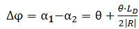
,其中R为液滴的曲率半径,由于在拉伸过程中只有

变小,这说明Δφ在变大,也即是说α
1和α
2的差值在扩大,液滴接触角α
1的减小比α
2慢,α
2先达到α
r,得到图6中的关于接触角变化过程曲线中的a-b段。
拉伸的AD 阶段:在这个阶段,接触角α
2=α
r ,并且随着拉伸接触角α
1持续变小,但是由于在α
2一侧的液滴接触线的后缩,其变化速度较小,得到图6中的关于接触角变化过程曲线中的b-c段。
拉伸的SD 阶段:此时,在亲水表面上,Δφ>0恒成立,因此不会出现Δφ→0的情况,该阶段不存在。
挤压的停滞阶段:在这个阶段,由于
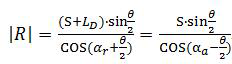
在增大,所以α
1和α
2都在变大,而
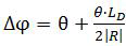
在变小也即是说α
1和α
2的差值在减小,但是当在亲水界面上时Δφ>0,得到图6中的关于接触角变化过程曲线中的e-f段。
挤压的AD阶段:在这个阶段,接触角α
1=α
2,接触角α
2变大。得到图6中的关于接触角变化过程曲线中的f-g段。
挤压的SD阶段:在这个阶段,液滴在前端和后端都有前进的趋势,但是在接触角滞后的阻力下,仍保持静止。
两个夹板502在张合运动的过程中,液滴内部流体的运动情况参见图7,其中,图7-a表示的是两个夹板502在挤压的过程中液滴内部的流体运动,图7-b表示的是两个夹板502在拉伸的过程中液滴内部的流体运动。内部的流体运动既导致了液滴的运动,也对液滴内的胚胎产生了剪切力。
本实施例还提供了一种基于液滴自驱动技术的胚胎动态培养方法,使用上述的培养装置,包括以下步骤:
(1)将已受精的胚胎701放在培养皿702中进行培养,培养皿702中放置了培养液703,胚胎701被包裹在培养液703中,如图8所示。
优选地,为了避免外界环境对胚胎701培养的影响,在培养液703上设置了油封704。
(2)将培养皿702放置于基底平台10上,调整旋转件20、机械手40使两个夹板502接触培养液703,形成液桥。
优选地,启动第一电机203,带动旋转板202转动,从而带动机械手40以及末端执行器50转动,接着启动第二电机301调整第一机械臂401的位置,通过曲柄连杆机构403带动第二机械臂402调整位置,使得两个夹板502接触培养液703,胚胎701处于两个夹板502之间,再启动旋转电机508调整两个夹板502之间的角度,直线电机505启动通过两个滑动支架506调整两个夹板502之间的距离。
(3)控制两个夹板502的运动速度。
通过控制直线电机505的速度来控制两个夹板502的运动速度,使培养液703在两个夹板502间的运动速度与胚胎701在输卵管中的运动速度的差值在预设范围内,并且使胚胎701在培养液703中受到的剪切力与预实验得到的最佳剪切力的差值在预设范围内。其中,培养液703在两个夹板502间的运动速度可以通过视觉传感器测得单位时间内运动的距离来计算。胚胎701在培养液703中受到的剪切力大小可以通过力传感器进行标定。
(4)观察胚胎701的发育过程,当胚胎701发育至桑椹胚时,动态培养结束。
对于本领域技术人员而言,显然本发明不限于上述示范性实施例的细节,而且在不背离本发明的精神或基本特征的情况下,能够以其他的具体形式实现本发明。
Claims (10)
- 一种基于液滴自驱动技术的胚胎动态培养装置,其特征在于,包括:基底平台;旋转件,设置在所述基底平台上;驱动机构,设置在所述旋转件上;机械手,所述机械手包括第一机械臂和第二机械臂,所述驱动机构驱动所述第一机械臂转动,所述第二机械臂能够相对于所述第一机械臂转动;末端执行器,所述末端执行器包括支架、设置在所述支架上的两个夹板,所述支架设置于所述第二机械臂,两个所述夹板能够相互平动或相互转动实现张合运动。
- 根据权利要求1所述的基于液滴自驱动技术的胚胎动态培养装置,其特征在于,所述旋转件包括基座、设置在所述基座上的旋转板以及设置在所述旋转板上的第一电机和两个侧板,所述基座固定在所述基底平台上,所述第一电机位于两个所述侧板之间,所述第一电机的转轴能够在所述基座内转动且与所述旋转板相连接。
- 根据权利要求2所述的基于液滴自驱动技术的胚胎动态培养装置,其特征在于,所述基座包括中空的第一基座以及设于所述第一基座内的第二基座,所述第一基座、第二基座均固定在所述基底平台上,所述旋转板设置在所述第一基座上,所述第一电机的转轴伸入所述第二基座内。
- 根据权利要求2所述的基于液滴自驱动技术的胚胎动态培养装置,其特征在于,所述驱动机构包括两个第二电机,所述第二电机设置在对应的所述侧板上。
- 根据权利要求1所述的基于液滴自驱动技术的胚胎动态培养装置,其特征在于,所述第二机械臂上铰接有曲柄连杆机构,所述旋转件上设置有立板,所述曲柄连杆机构的一端与所述立板的自由端相铰接,另一端与所述支架相铰接。
- 根据权利要求1所述的基于液滴自驱动技术的胚胎动态培养装置,其特征在于,所述基底平台包括第一平台和第二平台,所述第一平台的上表面低于所述第二平台的上表面。
- 根据权利要求1所述的基于液滴自驱动技术的胚胎动态培养装置,其特征在于,所述夹板的表面设置有疏液层。
- 根据权利要求1所述的基于液滴自驱动技术的胚胎动态培养装置,其特征在于,所述支架包括第一支撑架、设置在所述第一支撑架上的第二支撑架、设置于所述第二支撑架的直线电机以及由所述直线电机驱动的两个滑动旋转组件,所述滑动旋转组件包括滑动支架、与所述滑动支架相连接的支板、设置在所述支板上的旋转电机,所述旋转电机的转轴与对应的所述夹板相连接。
- 一种基于液滴自驱动技术的胚胎动态培养方法,其特征在于,使用如权利要求1-8中任一项所述的培养装置,包括以下步骤:(1)将已受精的胚胎放在培养皿中进行培养,胚胎被包裹在培养液中;(2)将培养皿放置于所述基底平台上,调整所述旋转件、机械手使两个所述夹板接触培养液,形成液桥;(3)控制两个所述夹板的运动速度;(4)观察胚胎的发育过程,当胚胎发育至桑椹胚时,动态培养结束。
- 根据权利要求9所述的基于液滴自驱动技术的胚胎动态培养方法,其特征在于,所述步骤(3)中,通过控制两个所述第一夹板的运动速度,使培养液在两个夹板间的运动速度与胚胎在输卵管中的运动速度的差值在预设范围内,并且使胚胎在培养液中受到的剪切力与预实验得到的最佳剪切力的差值在预设范围内。
Applications Claiming Priority (2)
| Application Number | Priority Date | Filing Date | Title |
|---|---|---|---|
| CN202111589839.XA CN114317265B (zh) | 2021-12-23 | 2021-12-23 | 基于液滴自驱动技术的胚胎动态培养装置及方法 |
| CN202111589839.X | 2021-12-23 |
Publications (1)
| Publication Number | Publication Date |
|---|---|
| WO2023116174A1 true WO2023116174A1 (zh) | 2023-06-29 |
Family
ID=81054362
Family Applications (1)
| Application Number | Title | Priority Date | Filing Date |
|---|---|---|---|
| PCT/CN2022/126985 Ceased WO2023116174A1 (zh) | 2021-12-23 | 2022-10-24 | 基于液滴自驱动技术的胚胎动态培养装置及方法 |
Country Status (2)
| Country | Link |
|---|---|
| CN (1) | CN114317265B (zh) |
| WO (1) | WO2023116174A1 (zh) |
Families Citing this family (1)
| Publication number | Priority date | Publication date | Assignee | Title |
|---|---|---|---|---|
| CN114317265B (zh) * | 2021-12-23 | 2023-04-18 | 苏州大学 | 基于液滴自驱动技术的胚胎动态培养装置及方法 |
Citations (8)
| Publication number | Priority date | Publication date | Assignee | Title |
|---|---|---|---|---|
| US6193647B1 (en) * | 1999-04-08 | 2001-02-27 | The Board Of Trustees Of The University Of Illinois | Microfluidic embryo and/or oocyte handling device and method |
| CN102796665A (zh) * | 2012-08-14 | 2012-11-28 | 中国人民解放军南京军区南京总医院 | 摆动式微动态培养箱 |
| CN102876573A (zh) * | 2012-10-26 | 2013-01-16 | 黑龙江八一农垦大学 | 一种哺乳动物胚胎体外培养器及其培养方法 |
| CN106607878A (zh) * | 2017-02-16 | 2017-05-03 | 浙江科技学院(浙江中德科技促进中心) | 光学元件专用模压机的六自由度机械手装置及其取放方法 |
| CN206357641U (zh) * | 2016-11-22 | 2017-07-28 | 广州造维科技有限公司 | 一种机械臂式3d打印机 |
| CN110787845A (zh) * | 2019-11-04 | 2020-02-14 | 苏州大学 | 液滴镊子以及液滴控制方法 |
| CN111282528A (zh) * | 2020-02-28 | 2020-06-16 | 苏州大学 | 基于液滴镊子的微反应器及方法 |
| CN114317265A (zh) * | 2021-12-23 | 2022-04-12 | 苏州大学 | 基于液滴自驱动技术的胚胎动态培养装置及方法 |
Family Cites Families (5)
| Publication number | Priority date | Publication date | Assignee | Title |
|---|---|---|---|---|
| US20130034906A1 (en) * | 2010-01-07 | 2013-02-07 | The Regents Of The University Of Michigan | Methods for in vitro oocyte maturation |
| EP3577208A4 (en) * | 2017-01-31 | 2020-12-02 | Genea IP Holdings Pty Limited | PROCESS AND SYSTEM FOR TREATMENT OF A BIOLOGICAL SAMPLE |
| CN212887613U (zh) * | 2020-05-05 | 2021-04-06 | 王辉 | 一种用于a4纸搬运的机械手臂 |
| CN111607516B (zh) * | 2020-06-09 | 2021-07-09 | 苏州大学 | 面向突破发育阻滞的早期胚胎拟输卵管环境体外培养芯片 |
| CN112847427A (zh) * | 2021-02-02 | 2021-05-28 | 昆明理工大学 | 一种五自由度折叠机械臂 |
-
2021
- 2021-12-23 CN CN202111589839.XA patent/CN114317265B/zh active Active
-
2022
- 2022-10-24 WO PCT/CN2022/126985 patent/WO2023116174A1/zh not_active Ceased
Patent Citations (8)
| Publication number | Priority date | Publication date | Assignee | Title |
|---|---|---|---|---|
| US6193647B1 (en) * | 1999-04-08 | 2001-02-27 | The Board Of Trustees Of The University Of Illinois | Microfluidic embryo and/or oocyte handling device and method |
| CN102796665A (zh) * | 2012-08-14 | 2012-11-28 | 中国人民解放军南京军区南京总医院 | 摆动式微动态培养箱 |
| CN102876573A (zh) * | 2012-10-26 | 2013-01-16 | 黑龙江八一农垦大学 | 一种哺乳动物胚胎体外培养器及其培养方法 |
| CN206357641U (zh) * | 2016-11-22 | 2017-07-28 | 广州造维科技有限公司 | 一种机械臂式3d打印机 |
| CN106607878A (zh) * | 2017-02-16 | 2017-05-03 | 浙江科技学院(浙江中德科技促进中心) | 光学元件专用模压机的六自由度机械手装置及其取放方法 |
| CN110787845A (zh) * | 2019-11-04 | 2020-02-14 | 苏州大学 | 液滴镊子以及液滴控制方法 |
| CN111282528A (zh) * | 2020-02-28 | 2020-06-16 | 苏州大学 | 基于液滴镊子的微反应器及方法 |
| CN114317265A (zh) * | 2021-12-23 | 2022-04-12 | 苏州大学 | 基于液滴自驱动技术的胚胎动态培养装置及方法 |
Also Published As
| Publication number | Publication date |
|---|---|
| CN114317265A (zh) | 2022-04-12 |
| CN114317265B (zh) | 2023-04-18 |
Similar Documents
| Publication | Publication Date | Title |
|---|---|---|
| WO2023116174A1 (zh) | 基于液滴自驱动技术的胚胎动态培养装置及方法 | |
| TWI335246B (en) | Coating device and coating method | |
| TW201119961A (en) | Scribing apparatus | |
| WO2019237471A1 (zh) | 一种基于连杆运动的食物吞咽模拟装置 | |
| CN108177283A (zh) | 吊装式手套浸胶机构 | |
| CN218599369U (zh) | 一种心脏超声检测用的投影设备 | |
| CN215661323U (zh) | 连续式生产夹具 | |
| CN215534289U (zh) | 一种光声成像装置 | |
| CN119386298B (zh) | 一种脑室引流装置 | |
| CN112478043B (zh) | 一种基于仿河鲀体刺的角度可调减阻装置 | |
| JP3965312B2 (ja) | 枚葉基板の製造装置 | |
| CN220450230U (zh) | 一种金属材料热处理用冷却装置 | |
| CN207889141U (zh) | 一种多关节柔性臂3d打印机 | |
| CN106706265B (zh) | 四自由度运动机构 | |
| CN113523190B (zh) | 船舶尾轴轴承套的加工装置及其加工方法 | |
| CN202281887U (zh) | 一种基板摩擦装置 | |
| CN206470037U (zh) | 四自由度运动机构 | |
| CN213464566U (zh) | 一种电动仿真模特装置 | |
| CN220471081U (zh) | 一种可自动旋转调整的led支架 | |
| CN217745593U (zh) | 一种乳腺癌术后康复装置 | |
| CN223176115U (zh) | 细胞应力加载系统 | |
| CN218973840U (zh) | 一种车轮涉水实验装置 | |
| CN107351060B (zh) | 一种仿生机器人头颈部柔性结构 | |
| CN214806651U (zh) | 一种糖尿病科护理装置 | |
| JP2005040696A (ja) | 液体塗布方法 |
Legal Events
| Date | Code | Title | Description |
|---|---|---|---|
| 121 | Ep: the epo has been informed by wipo that ep was designated in this application |
Ref document number: 22909492 Country of ref document: EP Kind code of ref document: A1 |
|
| NENP | Non-entry into the national phase |
Ref country code: DE |
|
| 122 | Ep: pct application non-entry in european phase |
Ref document number: 22909492 Country of ref document: EP Kind code of ref document: A1 |