WO2023112911A1 - Fusion connector - Google Patents
Fusion connector Download PDFInfo
- Publication number
- WO2023112911A1 WO2023112911A1 PCT/JP2022/045802 JP2022045802W WO2023112911A1 WO 2023112911 A1 WO2023112911 A1 WO 2023112911A1 JP 2022045802 W JP2022045802 W JP 2022045802W WO 2023112911 A1 WO2023112911 A1 WO 2023112911A1
- Authority
- WO
- WIPO (PCT)
- Prior art keywords
- groove
- optical fiber
- fiber
- group
- base member
- Prior art date
Links
Images


Classifications
-
- G—PHYSICS
- G02—OPTICS
- G02B—OPTICAL ELEMENTS, SYSTEMS OR APPARATUS
- G02B6/00—Light guides; Structural details of arrangements comprising light guides and other optical elements, e.g. couplings
- G02B6/24—Coupling light guides
- G02B6/255—Splicing of light guides, e.g. by fusion or bonding
Definitions
- This disclosure relates to a fusion splicer.
- Patent Document 1 Conventionally, there has been known a method of positioning an optical fiber to be spliced in a V-groove and performing fusion splicing (see Patent Document 1).
- a fusion splicer is a fusion splicer for fusion splicing one or more optical fibers to another optical fiber, wherein the one or more optical fibers are installed in one or A base member having a plurality of V-grooves is provided, and the base member is formed with one or more recesses crossing the one or more V-grooves.
- FIG. 1 is a perspective view of a portion of a fusion splicer.
- FIG. 2A is a top view of a portion of a fusion splicer.
- FIG. 2B is a top view of a portion of the fusion splicer.
- FIG. 3 is a cross-sectional view of part of a fusion splicer.
- FIG. 4 is a block diagram showing a control system for controlling the fusion splicer.
- FIG. 5 is a perspective view of part of a fusion splicer.
- FIG. 6A is a top view of a portion of a fusion splicer.
- FIG. 6B is a cross-sectional view of a portion of the fusion splicer.
- FIG. 1 is a perspective view of a portion of a fusion splicer.
- FIG. 2A is a top view of a portion of a fusion splicer.
- FIG. 2B is a top
- FIG. 7A is a cross-sectional view of part of a fusion splicer.
- FIG. 7B is a cross-sectional view of a portion of the fusion splicer.
- FIG. 7C is a cross-sectional view of a portion of the fusion splicer.
- FIG. 8A is a top view of a portion of a fusion splicer.
- FIG. 8B is a top view of a portion of the fusion splicer.
- FIG. 8C is a top view of a portion of the fusion splicer.
- Figure 8D is a top view of a portion of the fusion splicer.
- FIG. 8E is a top view of a portion of the fusion splicer.
- Figure 8F is a top view of a portion of the fusion splicer.
- FIG. 8G is a top view of a portion of the fusion splicer.
- Patent Document 1 discloses the operation of a fusion splicer for removing foreign matter adhering to an optical fiber.
- this fusion splicer needs to perform an operation for positively removing the foreign matter in addition to the normal fusion splicing operation. Therefore, it is desirable to minimize additional operations for foreign matter removal.
- the fusion splicer described above can prevent the position of the optical fiber installed in the V-groove from being displaced from the predetermined position due to foreign matter.
- a fusion splicer is a fusion splicer for fusion splicing one or more optical fibers to another optical fiber, wherein the one or more optical fibers are installed
- the base member may have one or more V-grooves formed therein, and the base member may be formed with one or more recesses crossing the one or more V-grooves.
- This configuration can reduce the probability of foreign matter remaining in the V-groove after the V-groove is cleaned with a cotton swab or the like by forming a recess across the V-groove. This is because foreign matter present in the V-groove is scraped out into the concave portion by a cotton swab or the like.
- this configuration has the effect of reducing the probability that a foreign object will be caught between the optical fiber and the V-groove when the optical fiber is installed in the V-groove.
- This configuration then has the advantage that the optical fiber is accurately positioned within the V-groove.
- the portion of the optical fiber that is installed in the V-groove is the portion where the coating material is removed and the glass fiber is exposed, and is also called a bare fiber portion.
- the portion coated with the coating material is also called an optical fiber bare wire or an optical fiber core wire.
- the depth of the one or more recesses may be deeper than the depth of the one or more V-grooves.
- the one or more recesses may be formed so as to extend in a direction non-parallel to the extending direction of the one or more V-grooves.
- the bottom surface of the one or more recesses may be formed so as to smoothly deepen from the end portion toward the center portion. This configuration makes it easier to scrape out the foreign matter accumulated on the bottom surface of the recess, so that foreign matter may be caught between the optical fiber and the V-groove when the optical fiber is installed in the V-groove. This brings about the effect of being able to further reduce the probability.
- the one or more recesses may be through holes penetrating through the base member. This configuration allows foreign matter entering the V-groove to be discharged out of the V-groove through the through-hole. Therefore, this configuration has the effect of further reducing the probability that a foreign object will be caught between the optical fiber and the V-groove when the optical fiber is installed in the V-groove.
- FIG. 1 is a perspective view of part of the fusion splicer 1.
- X1 represents one direction of the X-axis forming the three-dimensional orthogonal coordinate system
- X2 represents the other direction of the X-axis
- Y1 represents one direction of the Y-axis forming the three-dimensional orthogonal coordinate system
- Y2 represents the other direction of the Y-axis
- Z1 represents one direction of the Z-axis forming the three-dimensional orthogonal coordinate system
- Z2 represents the other direction of the Z-axis.
- the X1 side of the fusion splicer 1 corresponds to the front side (front side) of the fusion splicer 1
- the X2 side of the fusion splicer 1 corresponds to the rear side (back side) of the fusion splicer 1. side).
- the Y1 side of the fusion splicer 1 corresponds to the left side of the fusion splicer 1
- the Y2 side of the fusion splicer 1 corresponds to the right side of the fusion splicer 1 .
- the Z1 side of the fusion splicer 1 corresponds to the upper side of the fusion splicer 1
- the Z2 side of the fusion splicer 1 corresponds to the lower side of the fusion splicer 1 .
- the fusion splicer 1 is a device configured to fusion splice optical fibers arranged with their end faces facing each other by arc discharge.
- the fusion splicer 1 is configured to be capable of fusion splicing four optical fiber pairs.
- the fusion splicer 1 includes a pair of electrode rods 5 (rear electrode rod 5B and front electrode rod 5F), a pair of base members 11 (left base member 11L and right base member 11R), and a pair of It includes a fiber clamp assembly 21 (a left fiber clamp assembly 21L and a right fiber clamp assembly 21R) and a pair of fiber holders 31 (a left fiber holder 31L and a right fiber holder 31R).
- the pair of base members 11 (the left base member 11L and the right base member 11R) may be integrally formed as one component.
- the pair of electrode rods 5 includes a rear electrode rod 5B and a front electrode rod 5F that are spaced apart from each other in the X-axis direction.
- the pair of electrode rods 5 are arranged such that the tip 5Ba of the rear electrode rod 5B and the tip 5Fa of the front electrode rod 5F face each other in the X-axis direction.
- the rear electrode rod 5B includes a conical portion whose diameter decreases toward the tip 5Ba. The same applies to the front electrode rod 5F.
- a plurality of pairs of optical fibers arranged on the pair of base members 11 are glass fibers and arranged between the rear electrode rod 5B and the front electrode rod 5F for generating arc discharge. Also, among the plurality of pairs of optical fibers, the portions placed on the pair of base members 11 are bare fiber portions where the coating material is removed and the glass fibers are exposed.
- the plurality of pairs of bare fiber portions are a bare fiber portion of the left optical fiber group 3L that constitutes the left optical fiber ribbon 4L and a bare fiber portion of the right optical fiber group 3R that constitutes the right optical fiber ribbon 4R.
- the left optical fiber group 3L and the right optical fiber group 3R may be referred to as the optical fiber group 3 for convenience of explanation.
- a tape core wire is made by arranging multiple optical fibers (optical fiber strands) in parallel and coating them collectively with, for example, an ultraviolet curable resin (coating material).
- Each of the left optical fiber ribbon 4L and the right optical fiber ribbon 4R in the illustrated example is a four-fiber tape core in which four optical fibers (optical fiber bare wires) are arranged in parallel and collectively coated with an ultraviolet curable resin (coating material). is a line.
- the pair of base members 11 are members for supporting a plurality of pairs of optical fibers, and include a left base member 11L and a right base member 11R arranged so as to sandwich the pair of electrode rods 5 in the Y-axis direction. That is, the pair of electrode rods 5 are arranged between the left base member 11L and the right base member 11R which are arranged apart from each other in the Y-axis direction.
- the illustrated right base member 11R has a right V-groove group 17R, also referred to as a right optical fiber placement portion or right groove portion, and the left base member 11L is also referred to as a left optical fiber placement portion or left groove portion. It has a left V groove group 17L. Note that, hereinafter, the left V-groove group 17L and the right V-groove group 17R may be referred to as the V-groove group 17 for convenience of explanation.
- the left V-groove group 17L has a plurality of V-grooves for arranging a plurality of optical fibers (left optical fiber group 3L), and the right V-groove group 17R has a plurality of optical fibers (right optical fiber group 3R). ) for arranging a plurality of V-grooves.
- the left V-groove group 17L has four V-grooves for arranging four optical fibers.
- the four V-grooves are arranged at equal intervals in the X-axis direction and formed to extend linearly along the Y-axis direction.
- right V-groove group 17R has four V-grooves for arranging four optical fibers.
- the four V-grooves are arranged at equal intervals in the X-axis direction and formed to extend linearly along the Y-axis direction.
- the plurality of V-grooves in the right V-groove group 17R and the plurality of V-grooves in the left V-groove group 17L are configured so that positioning of a plurality of optical fiber pairs can be performed simultaneously.
- the four V-grooves in the right V-groove group 17R and the four V-grooves in the left V-groove group 17L are arranged to face each other in the extending direction (Y-axis direction), forming four optical fiber pairs. are configured to be positioned at the same time.
- the four optical fibers positioned by the four V-grooves in the right V-groove group 17R and the four optical fibers positioned by the four V-grooves in the left V-groove group 17L are connected to the right base member 11R. (Right V-groove group 17R) and Left base member 11L (Left V-groove group 17L) abut against each other.
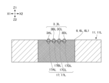
- FIGS. 2A and 2B are top views of part of the fusion splicer 1.
- FIGS. 2A and 2B are top views of the electrode rod 5 and the base member 11.
- FIG. 2A shows the state before the optical fiber group 3 is installed in the V-groove group 17, and
- FIG. 2B shows the state after the optical fiber group 3 is installed in the V-groove group 17. show.
- a dot pattern is added to the groove surface of the V groove group 17 for clarity.
- FIG. 2A the bottom of each V-groove is indicated by a dashed line. The same applies to FIGS. 6A and 8A to 8F, which will be described later.
- the left V-groove group 17L includes a first left V-groove 17AL, a second left V-groove 17BL, a third left V-groove 17CL, and a fourth left V-groove 17DL, and a right V-groove group 17R.
- a first right V-groove 17AR includes a first right V-groove 17AR, a second right V-groove 17BR, a third right V-groove 17CR, and a fourth right V-groove 17DR.
- the first left V-groove 17AL and the first right V-groove 17AR form a first V-groove pair 17A
- the second left V-groove 17BL and the second right V-groove 17BR form a second V-groove pair 17B
- the third left V-groove 17CL and the third right V-groove 17CR constitute a third V-groove pair 17C
- the fourth left V-groove 17DL and the fourth right V-groove 17DR constitute a fourth V-groove pair 17D.
- the left optical fiber group 3L includes a first left optical fiber 3AL, a second left optical fiber 3BL, a third left optical fiber 3CL, and a fourth left optical fiber 3DL as bare fiber portions.
- the right optical fiber group 3R includes a first right optical fiber 3AR, a second right optical fiber 3BR, a third right optical fiber 3CR, and a fourth right optical fiber 3DR as bare fiber portions.
- the first left optical fiber 3AL and the first right optical fiber 3AR constitute a first optical fiber pair 3A
- the second left optical fiber 3BL and the second right optical fiber 3BR constitute a second optical fiber pair 3B.
- the third left optical fiber 3CL and the third right optical fiber 3CR constitute a third optical fiber pair 3C
- the fourth left optical fiber 3DL and the fourth right optical fiber 3DR constitute a fourth optical fiber pair 3D. do.
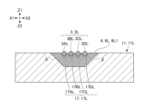
- FIG. 3 is a cross-sectional view of part of the fusion splicer 1.
- FIG. 3 is a view of the cross section including the section line III-III in FIG. 2B viewed from the X1 side as indicated by the arrow.
- the cross section in FIG. 2B includes the cross section of the base member 11 .
- the fiber clamp assembly 21 is configured so that the optical fiber group 3 installed in the V-groove group 17 can be pressed against the V-groove group 17, as shown in FIG.
- the fiber clamp assembly 21 includes an arm portion 21A, a fiber clamp 21B, a connecting pin 21C, and a clamp block 21D.
- the fiber clamp assembly 21 is arranged above the V-groove group 17 and configured to be movable in the Z-axis direction.
- the fiber clamp 21B is attached to the lower end of the arm portion 21A via a connecting pin 21C.
- the fiber clamp 21B is made of heat-resistant ceramics such as zirconia.
- the arm portion 21A is attached to the lower end of the clamp block 21D via an elastic body (not shown) such as a spring.
- the left fiber clamp assembly 21L is configured to be able to press the left optical fiber group 3L installed in the left V-groove group 17L against the left V-groove group 17L.
- the right fiber clamp assembly 21R is configured to be able to press the right optical fiber group 3R installed in the right V-groove group 17R against the right V-groove group 17R.
- the left fiber clamp assembly 21L includes a left arm portion 21AL, a left fiber clamp 21BL, a left connecting pin 21CL (see FIG. 3), and a left clamp block 21DL
- a right fiber clamp assembly 21R includes a right arm portion 21AR.
- the left fiber clamp assembly 21L is arranged above the left V-groove group 17L
- the right fiber clamp assembly 21R is arranged above the right V-groove group 17R.
- the left fiber clamp assembly 21L and the right fiber clamp assembly 21R are configured to be movable in the Z-axis direction.
- the left fiber clamp 21BL is attached to the lower end of the left arm portion 21AL via a left connecting pin 21CL
- the right fiber clamp 21BR is attached to the lower end of the right arm portion 21AR via a right connecting pin 21CR.
- the left fiber clamp 21BL is movable in the Z-axis direction together with the left arm portion 21AL
- the right fiber clamp 21BR is movable in the Z-axis direction together with the right arm portion 21AR.
- the left fiber clamp 21BL is separated from the left optical fiber group 3L installed in the left V-groove group 17L. can contact the left optical fiber group 3L and press the left optical fiber group 3L toward the left V-groove group 17L.
- the right fiber clamp 21BR is movable in the Z-axis direction together with the left arm portion 21AL
- the right fiber clamp 21BR is movable in the Z-axis direction together with the right arm portion 21AR.
- the left fiber clamp assembly 21L may be configured so that the fiber clamp pressure can be changed.
- the fiber clamp pressure is the pressure that the left optical fiber group 3L placed in the left V-groove group 17L receives from the left fiber clamp 21BL of the left fiber clamp assembly 21L.
- an elastic body such as a spring may be arranged between the left arm portion 21AL and the left clamp block 21DL to urge the left arm portion 21AL downward.
- the left fiber clamp assembly 21L can control the fiber clamp pressure by controlling the position of the left clamp block 21DL in the Z-axis direction. The same is true for the right fiber clamp assembly 21R.
- the left fiber holder 31L is configured to hold the left optical fiber group 3L
- the right fiber holder 31R is configured to hold the right optical fiber group 3R.
- the left fiber holder 31L is configured to hold the left ribbon core 4L including the left optical fiber group 3L
- the right fiber holder 31R is configured to hold the right ribbon core 4R including the right optical fiber group 3R. configured to hold.
- the left fiber holder 31L includes a left fiber holder main body 31La having a recess (not shown) for accommodating the left ribbon fiber 4L, and a left lid attached to the left fiber holder main body 31La. 31 Lb.
- the right fiber holder 31R includes a right fiber holder main body 31Ra having a recess (not shown) for accommodating the right fiber ribbon 4R, and a right lid 31Rb attached to the right fiber holder main body 31Ra. have.
- the left fiber ribbon 4L is held by the left fiber holder 31L by closing the left lid body 31Lb while the left fiber ribbon 4L is housed in the left fiber holder main body 31La.
- the left fiber holder 31L is fixed to a movable stage (not shown) and is movable in the direction along the axial direction of the left optical fiber group 3L. That is, the left fiber holder 31L can move along the extending direction (Y-axis direction) of the left V-groove group 17L.
- the held left optical fiber group 3L can move along the left V-groove group 17L.
- the right fiber ribbon 4R is held in the right fiber holder 31R by closing the right cover 31Rb while the right fiber holder main body 31Ra accommodates the right fiber ribbon 4R.
- the right fiber holder 31R is fixed to a movable stage (not shown) and is movable in the axial direction of the held right optical fiber group 3R. That is, the right fiber holder 31R is movable along the extending direction (Y-axis direction) of the right V-groove group 17R.
- the held right optical fiber group 3R can move along the right V-groove group 17R.
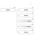
- FIG. 4 is a block diagram showing a control system for controlling the fusion splicer 1. As shown in FIG. 4
- the fusion splicer 1 includes an imaging device 51, a fusion device 52, a fiber clamp driving device 53, a fiber holder (stage) driving device 54, a display device 55, and a control device 60.
- the imaging device 51 , the fusion device 52 , the fiber clamp driving device 53 , the fiber holder (stage) driving device 54 and the display device 55 are controlled by the control device 60 .
- the imaging device 51 includes, for example, a pair of cameras (X camera and Y camera). Both the X camera and the Y camera can simultaneously image the end of the left optical fiber group 3L installed in the left V-groove group 17L and the end of the right optical fiber group 3R installed in the right V-groove group 17R. are arranged as Also, the imaging direction of the X camera and the imaging direction of the Y camera are orthogonal to each other.
- the control device 60 can identify the position of the optical fiber group 3 based on the images of the optical fiber group 3 captured from two different directions by the pair of cameras.
- the fusion splicer 52 is a device that fusion splices the end of the left optical fiber group 3L and the end of the right optical fiber group 3R.
- the pair of electrode rods 5 are included in the fusion device 52 .
- the fiber clamp driving device 53 is a device for pressing the optical fiber group 3 against the V groove group 17.
- the fiber clamp driving device 53 serves as an actuator for moving the left clamp block 21DL forming the left fiber clamp assembly 21L and the right clamp block 21DR forming the right fiber clamp assembly 21R in the Z-axis direction.
- the fiber holder (stage) driving device 54 is a device for moving the optical fiber group 3 in the axial direction (Y-axis direction).
- the fiber holder (stage) driving device 54 includes an actuator that moves the left fiber holder 31L fixed to the stage in a direction along the axial direction (Y-axis direction) of the left optical fiber group 3L, and a stage and an actuator for moving the right fiber holder 31R fixed to the right optical fiber group 3R along the axial direction (Y-axis direction) of the right optical fiber group 3R.
- the display device 55 is a device for displaying various information.
- the display device 55 is configured to display the image captured by the imaging device 51 .
- the display device 55 is a liquid crystal display.
- the control device 60 is a device for controlling each of the imaging device 51, the fusion splicing device 52, the fiber clamp driving device 53, the fiber holder (stage) driving device 54, and the display device 55.
- the control device 60 is a computer including, for example, a CPU (Central Processing Unit), RAM (Random Access Memory), ROM (Read Only Memory), a communication module, and an external storage device.
- the control device 60 acquires an image captured by the imaging device 51 by controlling the imaging device 51 .
- the control device 60 can cause the display device 55 to display the acquired image, for example.
- the control device 60 can determine the state of one or more pairs of optical fibers by performing image processing on the acquired image.
- the control device 60 can generate an arc discharge between the rear electrode rod 5B and the front electrode rod 5F by controlling the fusing device 52 .
- the control device 60 can move the left clamp block 21DL of the left fiber clamp assembly 21L and the right clamp block 21DR of the right fiber clamp assembly 21R in the Z-axis direction by controlling the fiber clamp drive device 53.
- the left fiber clamp assembly 21L can change the pressing state of the left optical fiber group 3L arranged in the left V-groove group 17L, and the right fiber clamp assembly 21R is arranged in the right V-groove group 17R. It is possible to change the pressing state of the right optical fiber group 3R.
- the controller 60 can control the positions of the left fiber holder 31L and the right fiber holder 31R in the Y-axis direction by controlling the fiber holder (stage) driving device 54 . Specifically, the control device 60 moves the stage (not shown) to which the left fiber holder 31L is fixed in the Y-axis direction, thereby moving the left optical fiber group 3L held by the left fiber holder 31L in the Y-axis direction. By moving the stage (not shown) to which the right fiber holder 31R is fixed in the Y-axis direction, the right optical fiber group 3R held by the right fiber holder 31R is moved in the Y-axis direction. be able to.
- the V-groove group 17 is used for positioning the optical fiber group 3 to be fusion-spliced.
- the foreign matter is, for example, dust in the ambient atmosphere, glass or coating material residue adhering to the optical fiber group 3 to be fusion spliced, or residue from the previous fusion splicing.
- FIG. 5 shows an example of the state of the optical fiber when foreign matter is present in the V-groove. Specifically, FIG. 5 shows the state of the first left optical fiber 3AL installed in the first left V-groove 17AL when the foreign matter G adheres to the first left V-groove 17AL, and the state of the foreign matter G. and the state of the first right optical fiber 3AR installed in the first right V-groove 17AR that is not attached.
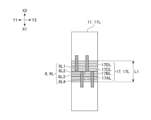
- recesses 6 are formed in each of the V-groove groups 17 in the fusion splicer 1 according to the present embodiment, as shown in FIGS. 1, 2A, 2B, and 3.
- the recess 6 is a portion (structure) formed in the base member 11 .
- the concave portion 6 has a structure formed so that foreign matter is less likely to adhere to the portion of the groove surface of the V-groove that is expected to come into contact with the optical fiber.
- the bottom surface and wall surfaces (side surfaces) of the recess 6, which is a recess formed in the base member 11, are provided with a cross pattern for clarity.
- the recess 6 includes a left recess 6L formed in the left base member 11L and a right recess 6R formed in the right base member 11R.
- the left recess 6L vertically crosses all four V-grooves (first left V-groove 17AL, second left V-groove 17BL, third left V-groove 17CL, and fourth left V-groove 17DL). and includes a first left recess 6L1 and a second left recess 6L2.
- the right concave portion 6R is formed so as to vertically cross all four V-grooves (first right V-groove 17AR, second right V-groove 17BR, third right V-groove 17CR, and fourth right V-groove 17DR).
- a formed groove comprising a first right recess 6R1 and a second right recess 6R2.
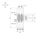
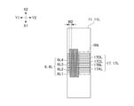
- FIGS. 6A and 6B are diagrams showing configuration examples of the left concave portion 6L formed on the upper surface of the left base member 11L, which is a part of the fusion splicer 1.
- FIG. 6A is a top view of the left base member 11L in which the left recessed portion 6L and the left V-groove group 17L are formed
- FIG. It is a sectional view of base member 11L.
- FIG. 6B is a view of the cross section including the section line VI-VI in FIG. 2B viewed from the Y2 side as indicated by the arrow. For clarity, in FIG.
- FIGS. 6A and 6B a dot pattern is added to the surface of the left V-groove group 17L.
- a cross pattern is given to the bottom surface and wall surface (side surface) of the left concave portion 6L for clarity. The same applies to FIGS. 7A, 7B, and 7C described later.
- the left V-groove group 17L is configured to have a length L1 in the X-axis direction.
- Each of the four V-grooves (first left V-groove 17AL, second left V-groove 17BL, third left V-groove 17CL, and fourth left V-groove 17DL) has a width WD and is The length L1 of the left V-groove group 17L corresponds to the total width of each of the four V-grooves.
- the first left concave portion 6L1 and the second left concave portion 6L2 are configured such that the length L2 in the X-axis direction is longer than the length L1 of the left V-groove group 17L.
- the first left concave portion 6L1 is longer forward (X1 direction) than the front edge (edge on the X1 side) of the left V-groove group 17L by a length L11. It is configured to be longer by a length L12 rearward (X2 direction) than the trailing edge (edge on the X2 side).
- the length L11 and the length L12 are the same. However, the length L11 and the length L12 may be different from each other.
- first left concave portion 6L1 and the second left concave portion 6L2 may be configured such that the length L2 in the X-axis direction is the same as the length L1 of the left V-groove group 17L. may be configured to be smaller.
- first left recess 6L1 and the second left recess 6L2 may be configured such that the length L2 in the X-axis direction is the same as the length L0 of the left base member 11L. That is, each of the first left concave portion 6L1 and the second left concave portion 6L2 is formed so that the front end opens to the front side surface of the left base member 11L and the rear end opens to the rear side surface of the left base member 11L. may Alternatively, each of the first left concave portion 6L1 and the second left concave portion 6L2 may be formed so that either the front end or the rear end thereof is open.
- the first left recessed portion 6L1 is configured to form a rectangular parallelepiped space having a width W2, a length L2, and a height (depth D2) inside the left base member 11L having a width W1. That is, the first left concave portion 6L1 includes a flat bottom surface extending along the X-axis direction and four wall surfaces extending along the Z-axis direction. The four wall surfaces are flat vertical surfaces, including a front side surface (X1 side surface), a rear side surface (X2 side surface), a left side surface (Y1 side surface), and a right side surface (Y2 side surface). . The same applies to the second left concave portion 6L2.
- the width W2 of the first left concave portion 6L1 is less than or equal to a predetermined size so that each of the left optical fiber groups 3L installed in the left V-groove group 17L does not loosen downward at the first left concave portion 6L1. is formed as The same applies to the second left concave portion 6L2.
- the left concave portion 6L is configured such that its depth D2 is deeper than the depth D1 of the left V-groove group 17L. This is so that the operator who removes the foreign matter with a cotton swab or the like can drop the foreign matter inside the left V-groove group 17L into the left concave portion 6L.
- the left concave portion 6L may be configured so that its depth D2 is the same as the depth D1 of the left V-groove group 17L, and the depth D2 is greater than the depth D1 of the left V-groove group 17L. It may be configured to be shallow.
- the left concave portion 6L may be configured to pass through the left base member 11L in the vertical direction (Z-axis direction). That is, the left concave portion 6L may be a rectangular parallelepiped through-hole penetrating the left base member 11L.
- the left recessed portion 6L is configured so that both the width of the opening and the width of the bottom surface are the width W2, but the width of the opening and the width of the bottom surface may be configured to be different from each other.
- the left concave portion 6L may be configured such that the width of the opening is larger than the width of the bottom surface.
- the left recessed portion 6L is configured such that both the length of the opening and the length of the bottom surface are the length L2. good.
- the left recessed portion 6L may be configured such that the length of the opening is greater than the length of the bottom surface. This is so that foreign matter that has fallen inside the left recessed portion 6L can be collected in a relatively narrow area on the bottom surface of the left recessed portion 6L. This is because it can be easily scraped out by
- the first left recess 6L1 is formed such that the distance between the left edge of the left base member 11L and the left edge of the first left recess 6L1 in the Y-axis direction is the width W21.
- the second left recess 6L2 is formed such that the distance between the right edge of the left base member 11L and the right edge of the second left recess 6L2 in the Y-axis direction is the width W22.
- the left recessed portion 6L (the first left recessed portion 6L1 and the second left recessed portion 6L2) has a width W31 between the right edge of the first left recessed portion 6L1 and the left edge of the second left recessed portion 6L2 in the Y-axis direction.
- the left recessed portion 6L (the first left recessed portion 6L1 and the second left recessed portion 6L2) is formed so that the width W21, the width W22, and the width W31 are the same.
- the left recessed portion 6L (the first left recessed portion 6L1 and the second left recessed portion 6L2) may be formed such that the width W21, the width W22, and the width W31 are different from each other.
- first left concave portion 6L1 and the second left concave portion 6L2 are formed to have the same width (width W2). good.
- first left recess 6L1 and the second left recess 6L2 are formed to have the same length (length L2), but have different lengths.
- first left recess 6L1 and the second left recess 6L2 are formed to have the same depth (depth D2), but have different depths.
- FIGS. 7A, 7B, and 7C are diagrams showing another configuration example of the recess 6.
- FIGS. 7A, 7B, and 7C are sectional views of the left base member 11L in which the left concave portion 6L and the left V-groove group 17L are formed, and correspond to FIG. 6B.
- FIGS. 7A, 7B, and 7C relate to the left recess 6L formed in the left base member 11L, it is similarly applied to the right recess 6R formed in the right base member 11R. be.
- the left recessed portion 6L shown in FIG. 7A differs from the left recessed portion 6L shown in FIG. 6B, which is configured to have a flat bottom surface, in that the bottom surface thereof is curved. Specifically, the bottom surface of the left concave portion 6L shown in FIG. 7A smoothly deepens from the front edge (edge on the X1 side) toward the center in the X-axis direction, and then from the center to the rear edge (edge on the X2 side). ) is configured to be smoothly shallow.
- the bottom surface of the left recessed portion 6L shown in FIG. 7A corresponds to the combination of the front side surface, the bottom surface, and the rear side surface of the left recessed portion 6L shown in FIG. 6B.
- both the left side and the right side of the left concave portion 6L shown in FIG. 7A are flat vertical surfaces, they may be inclined planes or inclined curved surfaces. Note that the inclined curved surface is typically a downwardly convex curved surface.
- the left recessed portion 6L shown in FIG. 7B has both the front side surface and the rear side surface formed by flat inclined surfaces, and the front side surface and the rear side surface are both formed by flat vertical surfaces as shown in FIG. 6B. It differs from the left concave portion 6L.
- the front side surface of the left recessed portion 6L shown in FIG. 7B is an inclined plane configured such that the angle between the upper surface of the left base member 11L and the front side surface is an angle ⁇ .
- the rear side surface is an inclined plane configured such that the angle between the upper surface of the left base member 11L and the rear side surface is an angle ⁇ .
- the slanted plane may be replaced with a slanted curved surface.
- both the left side surface and the right side surface of the left concave portion 6L shown in FIG. 7B are flat vertical surfaces, they may be inclined planes or inclined curved surfaces. Note that the inclined curved surface is typically a downwardly convex curved surface.
- the left recessed portion 6L shown in FIG. 7C differs from the left recessed portion 6L shown in FIG. 6B which is configured not to penetrate the left base member 11L in that it is configured to penetrate the left base member 11L.
- both the front side surface and the rear side surface of the left concave portion 6L shown in FIG. 7C are flat vertical surfaces, they may be inclined planes or inclined curved surfaces.
- both the left side and the right side of the left concave portion 6L shown in FIG. 7C are flat vertical surfaces, they may be inclined planes or inclined curved surfaces.
- FIGS. 7A and 7B compared to the configuration shown in FIG. 6B, have the effect of making it easier for the operator to scrape foreign matter from the left recessed portion 6L out of the left recessed portion 6L with a cotton swab or the like. Bring. Also, the configuration shown in FIG. 7C has the effect of preventing foreign matter from accumulating inside the left recessed portion 6L.
- FIGS. 8A to 8F are diagram showing still another configuration example of the recess 6.
- FIG. Specifically, each of FIGS. 8A to 8F is a top view of the left base member 11L in which the left concave portion 6L and the left V-groove group 17L are formed, and corresponds to FIG. 6A.
- FIGS. 8A to 8F relates to the left recess 6L formed in the left base member 11L, the same applies to the right recess 6R formed in the right base member 11R.
- Each of the first left concave portion 6L1 to the fourth left concave portion 6L4 included in the left concave portion 6L shown in FIG. 8A is a V groove included in the left V groove group 17L (the first left V groove 17AL to the fourth left V groove 17DL). of the left V-groove group 17L, i.e., not crossing the left V-groove group 17L over the entire width (length L1) of the left V-groove group 17L. It is different from the left concave portion 6L shown in FIG. 6B that traverses the left V-groove group 17L over the entire width (length L1).
- first left recessed portion 6L1 to fourth left recessed portion 6L4 aligned in the Y-axis direction
- two recessed portions aligned in the Y-axis direction. It differs from the left recess 6L shown in FIG. 6B which includes 6L1 and a second left recess 6L2).
- the first left concave portion 6L1 and the third left concave portion 6L3 are the third left V groove 17CL and the fourth left V groove, which are part of the V grooves included in the left V groove group 17L. It is formed so as to cross 17DL.
- the second left concave portion 6L2 and the fourth left concave portion 6L4 cross the first left V groove 17AL and the second left V groove 17BL, which are part of the V grooves included in the left V groove group 17L. is formed to In other words, the first left concave portion 6L1 and the third left concave portion 6L3 are formed so as not to cross the first left V-groove 17AL and the second left V-groove 17BL.
- the second left concave portion 6L2 and the fourth left concave portion 6L4 are formed so as not to cross the third left V-groove 17CL and the fourth left V-groove 17DL.
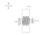
- the left recessed portion 6L shown in FIG. 8B is formed to obliquely cross the left V-groove group 17L. Different from 6L.
- the left recessed portion 6L shown in FIG. 8B includes five recessed portions (first left recessed portion 6L1 to fifth left recessed portion 6L5) aligned in the Y-axis direction, and two recessed portions (first left recessed portion) aligned in the Y-axis direction. It differs from the left recess 6L shown in FIG. 6B which includes 6L1 and a second left recess 6L2).
- the first left concave portion 6L1 obliquely crosses the first left V-groove 17AL and the second left V-groove 17BL, which are part of the V-grooves included in the left V-groove group 17L. is formed as
- the second left concave portion 6L2 to the fourth left concave portion 6L4 obliquely form the four V grooves (the first left V groove 17AL to the fourth left V groove 17DL) that are all the V grooves included in the left V groove group 17L.
- the fifth left concave portion 6L5 is formed so as to obliquely cross the third left V-groove 17CL and the fourth left V-groove 17DL, which are part of the V-grooves included in the left V-groove group 17L. It is
- the left recessed portion 6L shown in FIG. 8C includes two recessed portions (first left recessed portion 6L1 and second left recessed portion 6L2) that intersect with each other, and two recessed portions that do not intersect each other (first left recessed portion 6L1 and second left recessed portion 6L1). 6L2), unlike the left recess 6L shown in FIG. 6B.
- the first left concave portion 6L1 shown in FIG. 8C includes four V-grooves (from the first left V-groove 17AL to the fourth V-groove) from the left front side of the left V-groove group 17L to the right rear side of the left V-groove group 17L. 4 left V-groove 17DL).
- the second left concave portion 6L2 shown in FIG. 8C includes four V grooves (first left V groove 17AL to fourth left V groove 17AL) extending from the left rear side of the left V groove group 17L to the right front side of the left V groove group 17L. It is formed so as to obliquely cross all of the grooves 17DL).
- a first left concave portion 6L1 and a second left concave portion 6L2 shown in FIG. 8C are formed so as to intersect each other in the central portion of the left V-groove group 17L.
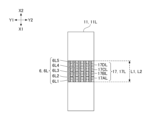
- the left concave portion 6L shown in FIG. 8D is formed so that its length L2 is the same as the length L1 of the left V-groove group 17L, and its length L2 is equal to the length L1 of the left V-groove group 17L. It is different from the left recessed portion 6L shown in FIG. 6B which is formed to be longer than the left recessed portion 6L.
- the left recessed portion 6L shown in FIG. 8D includes five recessed portions (first left recessed portion 6L1 to fifth left recessed portion 6L5) aligned in the Y-axis direction, and two recessed portions (first left recessed portion) aligned in the Y-axis direction. It differs from the left recess 6L shown in FIG. 6B which includes 6L1 and a second left recess 6L2).
- each of the five recesses is the same as the front edge (edge on the X1 side) of the first left V-groove 17AL.
- the rear edges (edges on the X2 side) of the five concave portions are aligned with the rear edges (edges on the X2 side) of the fourth left V-groove 17DL. ) is formed to match the
- the left edge (Y1 side edge) of the first left recess 6L1 shown in FIG. 8D is formed to match the left edge (Y1 side edge) of the left base member 11L. That is, the first left concave portion 6L1 shown in FIG. 8D is formed so that its left side is open, that is, it is formed so as to open to the left side surface of the left base member 11L.
- the left recessed portion 6L shown in FIG. 8E includes two recessed portions (first left recessed portion 6L1 and second left recessed portion 6L2) arranged in the Y-axis direction in that it is composed of one recessed portion (groove), as shown in FIG. 6B. It differs from the left concave portion 6L. Further, the left recessed portion 6L shown in FIG. 8E differs from the left recessed portion 6L shown in FIG. 6B in which the width W2 is constant in the X-axis direction in that the width W2 is not constant in the X-axis direction.
- the left concave portion 6L shown in FIG. W2 is formed to have a minimum width W2b.
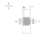
- the left recessed portion 6L shown in FIG. 8F differs from the left recessed portion 6L shown in FIG. 6B which is formed to extend linearly in the X-axis direction in that it is formed to extend while curving in the X-axis direction.
- the left recessed portion 6L shown in FIG. 8F includes four recessed portions (first left recessed portion 6L1 to fourth left recessed portion 6L4) aligned in the Y-axis direction, and two recessed portions (first left recessed portion) aligned in the Y-axis direction. It differs from the left recess 6L shown in FIG. 6B which includes 6L1 and a second left recess 6L2).
- each of the first left concave portion 6L1 to the fourth left concave portion 6L4 is formed so as to be curved so as to protrude toward the Y2 side in top view while maintaining a constant width W2.
- the left concave portion 6L shown in FIG. 8G is formed unevenly on one side of the upper surface of the left base member 11L. different from Further, the left recessed portion 6L shown in FIG. 8G differs from the left recessed portion 6L shown in FIG. 6B in which the width W2 is constant in the X-axis direction in that the width W2 is not constant in the X-axis direction.
- the left recessed portion 6L shown in FIG. 8G includes four recessed portions (first left recessed portion 6L1 to fourth left recessed portion 6L4) aligned in the Y-axis direction, and two recessed portions (first left recessed portion) aligned in the Y-axis direction. It differs from the left recess 6L shown in FIG. 6B which includes 6L1 and a second left recess 6L2).
- each of the first left recessed portion 6L1 to the fourth left recessed portion 6L4 is formed to be biased toward the left half of the upper surface of the left base member 11L.
- no recess is formed in the right half range of the upper surface of the left base member 11L, which is the range surrounded by the dashed line.
- recesses are not formed in a range relatively close to the electrode rod 5 for generating arc discharge, and recesses 6 are formed in a range relatively far from the electrode rod 5 .
- each of the first left recessed portion 6L1 and the third left recessed portion 6L3 is widened from the front edge (the edge on the X1 side) to the rear edge (the edge on the X2 side).
- Each of the second left concave portion 6L2 and the fourth left concave portion 6L4 is formed so that the width thereof narrows from the front edge (the edge on the X1 side) toward the rear edge (the edge on the X2 side).
- the left recessed portion 6L which can be configured in various ways as shown in FIGS. 8A to 8G, makes it easy for the operator to use a cotton swab or the like to remove foreign matter that has entered the left V-groove group 17L into the left recessed portion 6L. to Therefore, the left concave portion 6L, which can have various configurations as shown in FIGS. can be reduced. As a result, the left concave portion 6L, which can have various configurations as shown in FIGS. 8A to 8G, can prevent the position of the optical fiber installed in the V-groove from being displaced from the predetermined position due to foreign matter. .
- an operator who cleans the left V-groove group 17L with a cotton swab moves the tip of the cotton swab in the extending direction (Y-axis direction) of the V-groove while keeping the tip of the cotton swab in contact with the V-groove.
- foreign matter in the V-groove can be dropped into the nearest left concave portion 6L.
- the operator moves the tip of the cotton swab along the extending direction (X-axis direction) of the left recess 6L while keeping the tip of the cotton swab in contact with the bottom surface of the left recess 6L, thereby removing the foreign matter in the left recess 6L. can be scraped out of the left concave portion 6L.
- the right edge (Y2 side edge) of the rightmost recessed portion among the plurality of recessed portions is the right edge (Y2 side edge) of the left base member 11L. configured to be inconsistent. That is, the rightmost recess among the plurality of recesses is configured so that its right side is not open (it does not open on the right side surface of the left base member 11L). This is to ensure that a portion of the left optical fiber group 3L installed in the left V-groove group 17L, which is relatively close to the electrode rod 5, is supported by the left V-groove group 17L.
- the plurality of recesses are formed so that the intervals between the plurality of recesses are equal.
- the plurality of recesses may be formed such that the intervals between each of the plurality of recesses are unequal.
- one or more recesses are formed to have a front side surface (X1 side surface) and a rear side surface (X2 side surface). That is, the one or more recesses are configured so that neither the front side nor the rear side thereof is open. However, one or more recesses may be configured to be open on at least one of its front side and rear side.
- the first left concave portion 6L1 shown in FIG. 8A may be configured such that its rear end opens to the rear side surface of the left base member 11L.
- the fusion splicer 1 is configured to be able to fusion splice the first left optical fiber 3AL.
- the fusion splicer 1 includes a left base member 11L having a first left V-groove 17AL in which the first left optical fiber 3AL is installed.
- the left base member 11L is formed with a left concave portion 6L crossing the first left V-groove 17AL.
- This configuration can reduce the probability of foreign matter remaining in the V-groove after the V-groove is cleaned with a cotton swab or the like by forming a recess across the V-groove. Therefore, this configuration can prevent foreign matter from being caught between the optical fiber and the V-groove, and thus the position of the optical fiber installed in the V-groove can be displaced from the predetermined position due to the foreign matter. bring about the effect of being able to suppress the Also, this configuration provides an effect that a worker who cleans the V-groove with a cotton swab or the like can easily drop foreign matter in the V-groove into the nearest recessed portion 6 .
- the left base member 11L is typically configured such that the depth D2 of the first left recess 6L1 is deeper than the depth D1 of the left V-groove group 17L, as shown in FIG. 6B.
- the left base member 11L typically has four V-grooves (the depth D2 of each of the first left concave portion 6L1 and the second left concave portion 6L2) forming the left V-groove group 17L ( 17AL, second left V-groove 17BL, third left V-groove 17CL, and fourth left V-groove 17DL).
- the left base member 11L is typically formed so that the first left concave portion 6L1 extends in a direction non-parallel to the extending direction (Y-axis direction) of the left V-groove group 17L, as shown in FIG. 6A. It is In the example shown in FIG. 6A, the left base member 11L is formed such that the first left concave portion 6L1 extends in a direction (X-axis direction) perpendicular to the extending direction (Y-axis direction) of the left V-groove group 17L. .
- This configuration provides an effect that the operator who cleans the left V-groove group 17L can use a cotton swab or the like to scrape out foreign matter in a direction different from the extending direction (Y-axis direction) of the left V-groove group 17L. That is, the operator can discharge the foreign matter in the first left recessed portion 6L1 to the outside of the first left recessed portion 6L1 without returning it to the left V-groove group 17L. Therefore, this configuration has the effect of suppressing the position of the optical fiber installed in the V-groove from being displaced from the predetermined position due to foreign matter.
- the bottom surface of the first left concave portion 6L1 may be formed so as to smoothly deepen from the end portion toward the central portion.
- the bottom surface of the first left recess 6L1 is smooth and deep from the front end toward the center in the extending direction (X-axis direction) of the first left recess 6L1. and may be formed so as to smoothly deepen from the rear end portion toward the central portion.
- This configuration has the effect that the operator who cleans the left V-groove group 17L can easily discharge the foreign matter in the first left concave portion 6L1 to the outside using a cotton swab or the like. This is because there is no corner between the bottom surface and the wall surface of the first left concave portion 6L1 where foreign matter may remain.
- the bottom surface of the first left concave portion 6L1 may be formed so as to smoothly deepen from the central portion toward the end portion. This configuration provides an effect that foreign matter that has fallen into the first left recessed portion 6L1 can be collected at the end of the first left recessed portion 6L1.
- the fusion splicer 1 includes the left base member 11L formed with a plurality of V-grooves and the right base member 11R formed with a plurality of V-grooves.
- the fusion splicer 1 may include the left base member 11L having only one V-groove and the right base member 11R having only one V-groove. That is, the fusion splicer 1 may be a device for fusion splicing a single optical fiber.
Abstract
This fusion connector can suppress the position of an optical fiber installed in a V-groove from deviating from a predetermined position due to foreign substances. The fusion connector, which fuses and connects one or a plurality of optical fibers (3) to another optical fiber (3), comprises a base member (11) having one or a plurality of V-grooves (17) in which the one or the plurality of optical fibers (3) are installed, wherein the base member has one or a plurality of recess sections (6) which cross over the one or the plurality of V-grooves (17).
Description
本開示は、融着接続機に関する。
This disclosure relates to a fusion splicer.
本出願は、2021年12月16日出願の日本出願第2021-204601号に基づく優先権を主張し、前記日本出願に記載された全ての記載内容を援用するものである。
This application claims priority based on Japanese Application No. 2021-204601 filed on December 16, 2021, and incorporates all the content described in the Japanese application.
従来、接続対象の光ファイバをV溝内に位置決めして融着接続する方法が知られている(特許文献1参照。)。
Conventionally, there has been known a method of positioning an optical fiber to be spliced in a V-groove and performing fusion splicing (see Patent Document 1).
本開示の実施形態に係る融着接続機は、一又は複数の光ファイバを他の光ファイバと融着接続する融着接続機であって、前記一又は複数の光ファイバが設置される一又は複数のV溝を有するベース部材を備え、前記ベース部材には、前記一又は複数のV溝を横断する一又は複数の凹部が形成されている。
A fusion splicer according to an embodiment of the present disclosure is a fusion splicer for fusion splicing one or more optical fibers to another optical fiber, wherein the one or more optical fibers are installed in one or A base member having a plurality of V-grooves is provided, and the base member is formed with one or more recesses crossing the one or more V-grooves.
[本開示が解決しようとする課題]
特許文献1には、光ファイバに付着した異物を除去するための融着接続機の動作が開示されている。しかしながら、この融着接続機は、積極的に異物を除去するための動作を通常の融着接続のための動作に加えて行う必要がある。そこで、異物除去のための追加的な動作をなるべく少なくすることが望ましい。 [Problems to be Solved by the Present Disclosure]
Patent Document 1 discloses the operation of a fusion splicer for removing foreign matter adhering to an optical fiber. However, this fusion splicer needs to perform an operation for positively removing the foreign matter in addition to the normal fusion splicing operation. Therefore, it is desirable to minimize additional operations for foreign matter removal.
特許文献1には、光ファイバに付着した異物を除去するための融着接続機の動作が開示されている。しかしながら、この融着接続機は、積極的に異物を除去するための動作を通常の融着接続のための動作に加えて行う必要がある。そこで、異物除去のための追加的な動作をなるべく少なくすることが望ましい。 [Problems to be Solved by the Present Disclosure]
[本開示の効果]
上述の融着接続機は、V溝内に設置された光ファイバの位置が異物によって所定の位置からずれてしまうのを抑制できる。 [Effect of the present disclosure]
The fusion splicer described above can prevent the position of the optical fiber installed in the V-groove from being displaced from the predetermined position due to foreign matter.
上述の融着接続機は、V溝内に設置された光ファイバの位置が異物によって所定の位置からずれてしまうのを抑制できる。 [Effect of the present disclosure]
The fusion splicer described above can prevent the position of the optical fiber installed in the V-groove from being displaced from the predetermined position due to foreign matter.
[本開示の実施形態の説明]
最初に、本開示の実施態様を列記して説明する。 [Description of Embodiments of the Present Disclosure]
First, the embodiments of the present disclosure are listed and described.
最初に、本開示の実施態様を列記して説明する。 [Description of Embodiments of the Present Disclosure]
First, the embodiments of the present disclosure are listed and described.
(1)本開示の一態様に係る融着接続機は、一又は複数の光ファイバを他の光ファイバと融着接続する融着接続機であって、前記一又は複数の光ファイバが設置される一又は複数のV溝を有するベース部材を備え、前記ベース部材には、前記一又は複数のV溝を横断する一又は複数の凹部が形成されていてもよい。この構成は、V溝を横切るように凹部を形成することにより、綿棒等によってV溝の清掃が行われた後にV溝内に異物が残る確率を低下させることができる。綿棒等によってV溝内に存在する異物が凹部内に掻き出されるためである。そのため、この構成は、光ファイバをV溝内に設置する際に光ファイバとV溝との間に異物が挟み込まれてしまう確率を低下させることができるという効果をもたらす。そして、この構成は、光ファイバがV溝内に正確に位置決めされるようになるという効果をもたらす。なお、光ファイバのうち、V溝内に設置される部分は、被覆材が除去されてガラスファイバが露出した部分であり、裸ファイバ部分とも称される。また、被覆材で被覆された部分は、光ファイバ素線又は光ファイバ心線とも称される。
(1) A fusion splicer according to one aspect of the present disclosure is a fusion splicer for fusion splicing one or more optical fibers to another optical fiber, wherein the one or more optical fibers are installed The base member may have one or more V-grooves formed therein, and the base member may be formed with one or more recesses crossing the one or more V-grooves. This configuration can reduce the probability of foreign matter remaining in the V-groove after the V-groove is cleaned with a cotton swab or the like by forming a recess across the V-groove. This is because foreign matter present in the V-groove is scraped out into the concave portion by a cotton swab or the like. Therefore, this configuration has the effect of reducing the probability that a foreign object will be caught between the optical fiber and the V-groove when the optical fiber is installed in the V-groove. This configuration then has the advantage that the optical fiber is accurately positioned within the V-groove. The portion of the optical fiber that is installed in the V-groove is the portion where the coating material is removed and the glass fiber is exposed, and is also called a bare fiber portion. Moreover, the portion coated with the coating material is also called an optical fiber bare wire or an optical fiber core wire.
(2)前記一又は複数の凹部の深さは、前記一又は複数のV溝の深さよりも深くてもよい。この構成は、V溝から掻き出された異物がV溝よりも深い凹部内に落ちるため、光ファイバをV溝内に設置する際に光ファイバとV溝との間に異物が挟み込まれてしまう確率を更に低下させることができるという効果をもたらす。
(2) The depth of the one or more recesses may be deeper than the depth of the one or more V-grooves. With this configuration, foreign matter scraped out of the V-groove falls into the recess deeper than the V-groove, so that foreign matter is caught between the optical fiber and the V-groove when the optical fiber is installed in the V-groove. This brings about the effect of being able to further reduce the probability.
(3)前記一又は複数の凹部は、前記一又は複数のV溝の延在方向に非平行な方向に延びるように形成されていてもよい。この構成は、凹部内に溜まった異物を、V溝を経由せずに、凹部の延在方向に沿って外部に排出できるため、光ファイバをV溝内に設置する際に光ファイバとV溝との間に異物が挟み込まれてしまう確率を更に低下させることができるという効果をもたらす。
(3) The one or more recesses may be formed so as to extend in a direction non-parallel to the extending direction of the one or more V-grooves. With this configuration, foreign matter accumulated in the recess can be discharged outside along the extending direction of the recess without passing through the V-groove. It is possible to further reduce the probability that a foreign object will be caught between the .
(4)前記一又は複数の凹部の底面は、端部から中央部に向かって滑らかに深くなるように形成されていてもよい。この構成は、凹部の底面に溜まった異物の凹部の外への掻き出しを容易にするため、光ファイバをV溝内に設置する際に光ファイバとV溝との間に異物が挟み込まれてしまう確率を更に低下させることができるという効果をもたらす。
(4) The bottom surface of the one or more recesses may be formed so as to smoothly deepen from the end portion toward the center portion. This configuration makes it easier to scrape out the foreign matter accumulated on the bottom surface of the recess, so that foreign matter may be caught between the optical fiber and the V-groove when the optical fiber is installed in the V-groove. This brings about the effect of being able to further reduce the probability.
(5)前記一又は複数の凹部は、前記ベース部材を貫通する貫通孔であってもよい。この構成は、V溝内に進入した異物が貫通孔を通ってV溝の外に排出されるようにする。そのため、この構成は、光ファイバをV溝内に設置する際に光ファイバとV溝との間に異物が挟み込まれてしまう確率を更に低下させることができるという効果をもたらす。
(5) The one or more recesses may be through holes penetrating through the base member. This configuration allows foreign matter entering the V-groove to be discharged out of the V-groove through the through-hole. Therefore, this configuration has the effect of further reducing the probability that a foreign object will be caught between the optical fiber and the V-groove when the optical fiber is installed in the V-groove.
[本開示の実施形態の詳細]
以下では、添付図面を参照し、本開示の実施形態に係る融着接続機1及び光ファイバの接続方法の具体例を説明する。 [Details of the embodiment of the present disclosure]
A specific example of afusion splicer 1 and an optical fiber splicing method according to an embodiment of the present disclosure will be described below with reference to the accompanying drawings.
以下では、添付図面を参照し、本開示の実施形態に係る融着接続機1及び光ファイバの接続方法の具体例を説明する。 [Details of the embodiment of the present disclosure]
A specific example of a
図1は、融着接続機1の一部の斜視図である。図1において、X1は三次元直交座標系を構成するX軸の一方向を表し、X2はX軸の他方向を表す。また、Y1は三次元直交座標系を構成するY軸の一方向を表し、Y2はY軸の他方向を表す。同様に、Z1は三次元直交座標系を構成するZ軸の一方向を表し、Z2はZ軸の他方向を表す。本実施形態では、融着接続機1のX1側は、融着接続機1の前側(正面側)に相当し、融着接続機1のX2側は、融着接続機1の後側(背面側)に相当する。また、融着接続機1のY1側は、融着接続機1の左側に相当し、融着接続機1のY2側は、融着接続機1の右側に相当する。そして、融着接続機1のZ1側は、融着接続機1の上側に相当し、融着接続機1のZ2側は、融着接続機1の下側に相当する。他の図においても同様である。
FIG. 1 is a perspective view of part of the fusion splicer 1. FIG. In FIG. 1, X1 represents one direction of the X-axis forming the three-dimensional orthogonal coordinate system, and X2 represents the other direction of the X-axis. Y1 represents one direction of the Y-axis forming the three-dimensional orthogonal coordinate system, and Y2 represents the other direction of the Y-axis. Similarly, Z1 represents one direction of the Z-axis forming the three-dimensional orthogonal coordinate system, and Z2 represents the other direction of the Z-axis. In this embodiment, the X1 side of the fusion splicer 1 corresponds to the front side (front side) of the fusion splicer 1, and the X2 side of the fusion splicer 1 corresponds to the rear side (back side) of the fusion splicer 1. side). The Y1 side of the fusion splicer 1 corresponds to the left side of the fusion splicer 1 , and the Y2 side of the fusion splicer 1 corresponds to the right side of the fusion splicer 1 . The Z1 side of the fusion splicer 1 corresponds to the upper side of the fusion splicer 1 , and the Z2 side of the fusion splicer 1 corresponds to the lower side of the fusion splicer 1 . The same applies to other drawings.
融着接続機1は、端面同士を突き合わせて配列される光ファイバ同士をアーク放電によって互いに融着接続できるように構成された装置である。図示例では、融着接続機1は、四つの光ファイバ対を融着接続できるように構成されている。具体的には、融着接続機1は、一対の電極棒5(後電極棒5B及び前電極棒5F)と、一対のベース部材11(左ベース部材11L及び右ベース部材11R)と、一対のファイバクランプアセンブリ21(左ファイバクランプアセンブリ21L及び右ファイバクランプアセンブリ21R)と、一対のファイバホルダ31(左ファイバホルダ31L及び右ファイバホルダ31R)とを含む。なお、一対のベース部材11(左ベース部材11L及び右ベース部材11R)は、一部品として一体的に形成されていてもよい。
The fusion splicer 1 is a device configured to fusion splice optical fibers arranged with their end faces facing each other by arc discharge. In the illustrated example, the fusion splicer 1 is configured to be capable of fusion splicing four optical fiber pairs. Specifically, the fusion splicer 1 includes a pair of electrode rods 5 (rear electrode rod 5B and front electrode rod 5F), a pair of base members 11 (left base member 11L and right base member 11R), and a pair of It includes a fiber clamp assembly 21 (a left fiber clamp assembly 21L and a right fiber clamp assembly 21R) and a pair of fiber holders 31 (a left fiber holder 31L and a right fiber holder 31R). The pair of base members 11 (the left base member 11L and the right base member 11R) may be integrally formed as one component.
一対の電極棒5は、X軸方向に互いに離間して配置される後電極棒5B及び前電極棒5Fを含む。一対の電極棒5は、X軸方向において後電極棒5Bの先端5Baと前電極棒5Fの先端5Faとが互いに対向するように配置されている。図示例では、後電極棒5Bは、先端5Baに向かうにつれて径が小さくなる円錐状の部分を含む。前電極棒5Fについても同様である。
The pair of electrode rods 5 includes a rear electrode rod 5B and a front electrode rod 5F that are spaced apart from each other in the X-axis direction. The pair of electrode rods 5 are arranged such that the tip 5Ba of the rear electrode rod 5B and the tip 5Fa of the front electrode rod 5F face each other in the X-axis direction. In the illustrated example, the rear electrode rod 5B includes a conical portion whose diameter decreases toward the tip 5Ba. The same applies to the front electrode rod 5F.
一対のベース部材11の上に配置される複数対の光ファイバは、ガラスファイバであり、アーク放電を発生させるための後電極棒5Bと前電極棒5Fとの間に配置される。また、複数対の光ファイバのうち、一対のベース部材11の上に設置される部分は、被覆材が除去されてガラスファイバが露出した裸ファイバ部分である。
A plurality of pairs of optical fibers arranged on the pair of base members 11 are glass fibers and arranged between the rear electrode rod 5B and the front electrode rod 5F for generating arc discharge. Also, among the plurality of pairs of optical fibers, the portions placed on the pair of base members 11 are bare fiber portions where the coating material is removed and the glass fibers are exposed.
具体的には、複数対の裸ファイバ部分は、左テープ心線4Lを構成する左光ファイバ群3Lの裸ファイバ部分と、右テープ心線4Rを構成する右光ファイバ群3Rの裸ファイバ部分とを含む。なお、以下では、左光ファイバ群3L及び右光ファイバ群3Rは、説明の便宜上、光ファイバ群3と称される場合がある。
Specifically, the plurality of pairs of bare fiber portions are a bare fiber portion of the left optical fiber group 3L that constitutes the left optical fiber ribbon 4L and a bare fiber portion of the right optical fiber group 3R that constitutes the right optical fiber ribbon 4R. including. In the following description, the left optical fiber group 3L and the right optical fiber group 3R may be referred to as the optical fiber group 3 for convenience of explanation.
テープ心線は、複数本の光ファイバ(光ファイバ素線)を平行に並べ、例えば紫外線硬化型樹脂(被覆材)で一括被覆したものである。図示例の左テープ心線4L及び右テープ心線4Rのそれぞれは、四本の光ファイバ(光ファイバ素線)を平行に並べ、紫外線硬化型樹脂(被覆材)で一括被覆した4心テープ心線である。
A tape core wire is made by arranging multiple optical fibers (optical fiber strands) in parallel and coating them collectively with, for example, an ultraviolet curable resin (coating material). Each of the left optical fiber ribbon 4L and the right optical fiber ribbon 4R in the illustrated example is a four-fiber tape core in which four optical fibers (optical fiber bare wires) are arranged in parallel and collectively coated with an ultraviolet curable resin (coating material). is a line.
一対のベース部材11は、複数対の光ファイバを支持するための部材であり、Y軸方向において一対の電極棒5を挟むように配置される左ベース部材11Lと右ベース部材11Rとを含む。即ち、一対の電極棒5は、Y軸方向において互いに離間して配置される左ベース部材11Lと右ベース部材11Rとの間に配置される。図示例の右ベース部材11Rは、右光ファイバ配置部又は右溝部分とも称される右V溝群17Rを有し、左ベース部材11Lは、左光ファイバ配置部又は左溝部分とも称される左V溝群17Lを有する。なお、以下では、左V溝群17L及び右V溝群17Rは、説明の便宜上、V溝群17と称される場合がある。
The pair of base members 11 are members for supporting a plurality of pairs of optical fibers, and include a left base member 11L and a right base member 11R arranged so as to sandwich the pair of electrode rods 5 in the Y-axis direction. That is, the pair of electrode rods 5 are arranged between the left base member 11L and the right base member 11R which are arranged apart from each other in the Y-axis direction. The illustrated right base member 11R has a right V-groove group 17R, also referred to as a right optical fiber placement portion or right groove portion, and the left base member 11L is also referred to as a left optical fiber placement portion or left groove portion. It has a left V groove group 17L. Note that, hereinafter, the left V-groove group 17L and the right V-groove group 17R may be referred to as the V-groove group 17 for convenience of explanation.
左V溝群17Lは、複数本の光ファイバ(左光ファイバ群3L)を配置するための複数のV溝を有し、右V溝群17Rは、複数本の光ファイバ(右光ファイバ群3R)を配置するための複数のV溝を有する。図示例では、左V溝群17Lは、四本の光ファイバを配置するための四つのV溝を有する。そして、四つのV溝は、X軸方向に等間隔で配置され、且つ、Y軸方向に沿って直線状に延びるように形成されている。同様に、右V溝群17Rは、四本の光ファイバを配置するための四つのV溝を有する。四つのV溝は、X軸方向に等間隔で配置され、且つ、Y軸方向に沿って直線状に延びるように形成されている。
The left V-groove group 17L has a plurality of V-grooves for arranging a plurality of optical fibers (left optical fiber group 3L), and the right V-groove group 17R has a plurality of optical fibers (right optical fiber group 3R). ) for arranging a plurality of V-grooves. In the illustrated example, the left V-groove group 17L has four V-grooves for arranging four optical fibers. The four V-grooves are arranged at equal intervals in the X-axis direction and formed to extend linearly along the Y-axis direction. Similarly, right V-groove group 17R has four V-grooves for arranging four optical fibers. The four V-grooves are arranged at equal intervals in the X-axis direction and formed to extend linearly along the Y-axis direction.
右V溝群17Rにおける複数のV溝と左V溝群17Lにおける複数のV溝とは、複数の光ファイバ対の位置決めが同時に行われるように構成されている。図示例では、右V溝群17Rにおける四つのV溝と左V溝群17Lにおける四つのV溝とは、延在方向(Y軸方向)において互いに対向するように配置され、四つの光ファイバ対の位置決めが同時に行われるように構成されている。
The plurality of V-grooves in the right V-groove group 17R and the plurality of V-grooves in the left V-groove group 17L are configured so that positioning of a plurality of optical fiber pairs can be performed simultaneously. In the illustrated example, the four V-grooves in the right V-groove group 17R and the four V-grooves in the left V-groove group 17L are arranged to face each other in the extending direction (Y-axis direction), forming four optical fiber pairs. are configured to be positioned at the same time.
これにより、右V溝群17Rにおける四つのV溝によって位置決めされた四本の光ファイバと、左V溝群17Lにおける四つのV溝によって位置決めされた四本の光ファイバとは、右ベース部材11R(右V溝群17R)と左ベース部材11L(左V溝群17L)との間の領域において互いに突き合わされる。
As a result, the four optical fibers positioned by the four V-grooves in the right V-groove group 17R and the four optical fibers positioned by the four V-grooves in the left V-groove group 17L are connected to the right base member 11R. (Right V-groove group 17R) and Left base member 11L (Left V-groove group 17L) abut against each other.
ここで、図2A及び図2Bを参照し、四つの光ファイバ対が位置決めされるV溝群17の詳細について説明する。図2A及び図2Bは、融着接続機1の一部の上面図である。具体的には、図2A及び図2Bは、電極棒5及びベース部材11の上面図である。より具体的には、図2Aは、光ファイバ群3がV溝群17に設置される前の状態を示し、図2Bは、光ファイバ群3がV溝群17に設置された後の状態を示す。なお、図2A及び図2Bでは、明瞭化のため、V溝群17の溝表面にはドットパターンが付されている。また、図2Aでは、各V溝の底部は破線で表されている。後掲の図6A及び図8Aから図8Fにおいても同様である。
The details of the V-groove group 17 in which the four optical fiber pairs are positioned will now be described with reference to FIGS. 2A and 2B. 2A and 2B are top views of part of the fusion splicer 1. FIG. Specifically, FIGS. 2A and 2B are top views of the electrode rod 5 and the base member 11. FIG. More specifically, FIG. 2A shows the state before the optical fiber group 3 is installed in the V-groove group 17, and FIG. 2B shows the state after the optical fiber group 3 is installed in the V-groove group 17. show. In addition, in FIGS. 2A and 2B, a dot pattern is added to the groove surface of the V groove group 17 for clarity. Also, in FIG. 2A, the bottom of each V-groove is indicated by a dashed line. The same applies to FIGS. 6A and 8A to 8F, which will be described later.
図2Aに示すように、左V溝群17Lは、第1左V溝17AL、第2左V溝17BL、第3左V溝17CL、及び第4左V溝17DLを含み、右V溝群17Rは、第1右V溝17AR、第2右V溝17BR、第3右V溝17CR、及び第4右V溝17DRを含む。そして、第1左V溝17ALと第1右V溝17ARとは第1V溝対17Aを構成し、第2左V溝17BLと第2右V溝17BRとは第2V溝対17Bを構成し、第3左V溝17CLと第3右V溝17CRとは第3V溝対17Cを構成し、第4左V溝17DLと第4右V溝17DRとは第4V溝対17Dを構成する。
As shown in FIG. 2A, the left V-groove group 17L includes a first left V-groove 17AL, a second left V-groove 17BL, a third left V-groove 17CL, and a fourth left V-groove 17DL, and a right V-groove group 17R. includes a first right V-groove 17AR, a second right V-groove 17BR, a third right V-groove 17CR, and a fourth right V-groove 17DR. The first left V-groove 17AL and the first right V-groove 17AR form a first V-groove pair 17A, the second left V-groove 17BL and the second right V-groove 17BR form a second V-groove pair 17B, The third left V-groove 17CL and the third right V-groove 17CR constitute a third V-groove pair 17C, and the fourth left V-groove 17DL and the fourth right V-groove 17DR constitute a fourth V-groove pair 17D.
また、図2Bに示すように、左光ファイバ群3Lは、裸ファイバ部分としての第1左光ファイバ3AL、第2左光ファイバ3BL、第3左光ファイバ3CL、及び第4左光ファイバ3DLを含み、右光ファイバ群3Rは、裸ファイバ部分としての第1右光ファイバ3AR、第2右光ファイバ3BR、第3右光ファイバ3CR、及び第4右光ファイバ3DRを含む。そして、第1左光ファイバ3ALと第1右光ファイバ3ARとは第1光ファイバ対3Aを構成し、第2左光ファイバ3BLと第2右光ファイバ3BRとは第2光ファイバ対3Bを構成し、第3左光ファイバ3CLと第3右光ファイバ3CRとは第3光ファイバ対3Cを構成し、第4左光ファイバ3DLと第4右光ファイバ3DRとは第4光ファイバ対3Dを構成する。
Also, as shown in FIG. 2B, the left optical fiber group 3L includes a first left optical fiber 3AL, a second left optical fiber 3BL, a third left optical fiber 3CL, and a fourth left optical fiber 3DL as bare fiber portions. Including, the right optical fiber group 3R includes a first right optical fiber 3AR, a second right optical fiber 3BR, a third right optical fiber 3CR, and a fourth right optical fiber 3DR as bare fiber portions. The first left optical fiber 3AL and the first right optical fiber 3AR constitute a first optical fiber pair 3A, and the second left optical fiber 3BL and the second right optical fiber 3BR constitute a second optical fiber pair 3B. The third left optical fiber 3CL and the third right optical fiber 3CR constitute a third optical fiber pair 3C, and the fourth left optical fiber 3DL and the fourth right optical fiber 3DR constitute a fourth optical fiber pair 3D. do.
次に、図1及び図3を参照し、ファイバクランプアセンブリ21(左ファイバクランプアセンブリ21L及び右ファイバクランプアセンブリ21R)の動きについて説明する。図3は、融着接続機1の一部の断面図である。具体的には、図3は、図2Bにおける切断線III-IIIを含む断面を矢印で示すようにX1側から見たときの図である。なお、図2Bにおける断面は、ベース部材11の断面を含む。
Next, movement of the fiber clamp assembly 21 (left fiber clamp assembly 21L and right fiber clamp assembly 21R) will be described with reference to FIGS. FIG. 3 is a cross-sectional view of part of the fusion splicer 1. FIG. Specifically, FIG. 3 is a view of the cross section including the section line III-III in FIG. 2B viewed from the X1 side as indicated by the arrow. In addition, the cross section in FIG. 2B includes the cross section of the base member 11 .
ファイバクランプアセンブリ21は、図1に示すように、V溝群17に設置された光ファイバ群3をV溝群17に押し付けることができるように構成されている。図示例では、ファイバクランプアセンブリ21は、アーム部21A、ファイバクランプ21B、連結ピン21C、及びクランプブロック21Dを含む。ファイバクランプアセンブリ21は、V溝群17の上方に配置され、Z軸方向に移動できるように構成されている。ファイバクランプ21Bは、連結ピン21Cを介してアーム部21Aの下端に取り付けられている。図示例では、ファイバクランプ21Bは、ジルコニア等の耐熱性セラミックスで形成されている。アーム部21Aは、バネ等の弾性体(図示せず)を介してクランプブロック21Dの下端に取り付けられている。
The fiber clamp assembly 21 is configured so that the optical fiber group 3 installed in the V-groove group 17 can be pressed against the V-groove group 17, as shown in FIG. In the illustrated example, the fiber clamp assembly 21 includes an arm portion 21A, a fiber clamp 21B, a connecting pin 21C, and a clamp block 21D. The fiber clamp assembly 21 is arranged above the V-groove group 17 and configured to be movable in the Z-axis direction. The fiber clamp 21B is attached to the lower end of the arm portion 21A via a connecting pin 21C. In the illustrated example, the fiber clamp 21B is made of heat-resistant ceramics such as zirconia. The arm portion 21A is attached to the lower end of the clamp block 21D via an elastic body (not shown) such as a spring.
具体的には、左ファイバクランプアセンブリ21Lは、左V溝群17Lに設置された左光ファイバ群3Lを左V溝群17Lに押し付けることができるように構成されている。同様に、右ファイバクランプアセンブリ21Rは、右V溝群17Rに設置された右光ファイバ群3Rを右V溝群17Rに押し付けることができるように構成されている。図示例では、左ファイバクランプアセンブリ21Lは、左アーム部21AL、左ファイバクランプ21BL、左連結ピン21CL(図3参照)、及び左クランプブロック21DLを含み、右ファイバクランプアセンブリ21Rは、右アーム部21AR、右ファイバクランプ21BR、右連結ピン21CR、及び右クランプブロック21DRを含む。左ファイバクランプアセンブリ21Lは、左V溝群17Lの上方に配置されており、右ファイバクランプアセンブリ21Rは、右V溝群17Rの上方に配置されている。また、左ファイバクランプアセンブリ21L及び右ファイバクランプアセンブリ21Rは、Z軸方向に移動できるように構成されている。そして、左ファイバクランプ21BLは左連結ピン21CLを介して左アーム部21ALの下端に取り付けられ、右ファイバクランプ21BRは右連結ピン21CRを介して右アーム部21ARの下端に取り付けられている。図示例では、左ファイバクランプ21BLは左アーム部21ALとともにZ軸方向に移動可能となっており、右ファイバクランプ21BRは右アーム部21ARとともにZ軸方向に移動可能となっている。図3に示す状態では、左ファイバクランプ21BLが左V溝群17Lに設置された左光ファイバ群3Lから離間しているが、左ファイバクランプアセンブリ21Lが下方に移動することによって、左ファイバクランプ21BLは、左光ファイバ群3Lと接触し、左光ファイバ群3Lを左V溝群17Lに向けて押し付けることができる。右ファイバクランプ21BRについても同様である。
Specifically, the left fiber clamp assembly 21L is configured to be able to press the left optical fiber group 3L installed in the left V-groove group 17L against the left V-groove group 17L. Similarly, the right fiber clamp assembly 21R is configured to be able to press the right optical fiber group 3R installed in the right V-groove group 17R against the right V-groove group 17R. In the illustrated example, the left fiber clamp assembly 21L includes a left arm portion 21AL, a left fiber clamp 21BL, a left connecting pin 21CL (see FIG. 3), and a left clamp block 21DL, and a right fiber clamp assembly 21R includes a right arm portion 21AR. , a right fiber clamp 21BR, a right connecting pin 21CR, and a right clamp block 21DR. The left fiber clamp assembly 21L is arranged above the left V-groove group 17L, and the right fiber clamp assembly 21R is arranged above the right V-groove group 17R. Also, the left fiber clamp assembly 21L and the right fiber clamp assembly 21R are configured to be movable in the Z-axis direction. The left fiber clamp 21BL is attached to the lower end of the left arm portion 21AL via a left connecting pin 21CL, and the right fiber clamp 21BR is attached to the lower end of the right arm portion 21AR via a right connecting pin 21CR. In the illustrated example, the left fiber clamp 21BL is movable in the Z-axis direction together with the left arm portion 21AL, and the right fiber clamp 21BR is movable in the Z-axis direction together with the right arm portion 21AR. In the state shown in FIG. 3, the left fiber clamp 21BL is separated from the left optical fiber group 3L installed in the left V-groove group 17L. can contact the left optical fiber group 3L and press the left optical fiber group 3L toward the left V-groove group 17L. The same applies to the right fiber clamp 21BR.
左ファイバクランプアセンブリ21Lは、ファイバクランプ圧を変化させることができるように構成されていてもよい。ファイバクランプ圧は、左V溝群17Lに設置された左光ファイバ群3Lが左ファイバクランプアセンブリ21Lの左ファイバクランプ21BLから受ける圧力である。具体的には、左アーム部21ALと左クランプブロック21DLとの間には、左アーム部21ALを下向きに付勢するバネ等の弾性体が配置されていてもよい。この場合、左ファイバクランプアセンブリ21Lは、Z軸方向における左クランプブロック21DLの位置を制御することによって、ファイバクランプ圧を制御することができる。右ファイバクランプアセンブリ21Rについても同様である。
The left fiber clamp assembly 21L may be configured so that the fiber clamp pressure can be changed. The fiber clamp pressure is the pressure that the left optical fiber group 3L placed in the left V-groove group 17L receives from the left fiber clamp 21BL of the left fiber clamp assembly 21L. Specifically, an elastic body such as a spring may be arranged between the left arm portion 21AL and the left clamp block 21DL to urge the left arm portion 21AL downward. In this case, the left fiber clamp assembly 21L can control the fiber clamp pressure by controlling the position of the left clamp block 21DL in the Z-axis direction. The same is true for the right fiber clamp assembly 21R.
また、図1に示すように、左ファイバホルダ31Lは、左光ファイバ群3Lを保持できるように構成され、右ファイバホルダ31Rは、右光ファイバ群3Rを保持できるように構成されている。具体的には、左ファイバホルダ31Lは、左光ファイバ群3Lを含む左テープ心線4Lを保持できるように構成され、右ファイバホルダ31Rは、右光ファイバ群3Rを含む右テープ心線4Rを保持できるように構成されている。より具体的には、左ファイバホルダ31Lは、左テープ心線4Lを収容するための凹部(図示せず。)を有する左ファイバホルダ本体31Laと、左ファイバホルダ本体31Laに取り付けられた左蓋体31Lbとを有する。同様に、右ファイバホルダ31Rは、右テープ心線4Rを収容するための凹部(図示せず。)を有する右ファイバホルダ本体31Raと、右ファイバホルダ本体31Raに取り付けられた右蓋体31Rbとを有する。
Also, as shown in FIG. 1, the left fiber holder 31L is configured to hold the left optical fiber group 3L, and the right fiber holder 31R is configured to hold the right optical fiber group 3R. Specifically, the left fiber holder 31L is configured to hold the left ribbon core 4L including the left optical fiber group 3L, and the right fiber holder 31R is configured to hold the right ribbon core 4R including the right optical fiber group 3R. configured to hold. More specifically, the left fiber holder 31L includes a left fiber holder main body 31La having a recess (not shown) for accommodating the left ribbon fiber 4L, and a left lid attached to the left fiber holder main body 31La. 31 Lb. Similarly, the right fiber holder 31R includes a right fiber holder main body 31Ra having a recess (not shown) for accommodating the right fiber ribbon 4R, and a right lid 31Rb attached to the right fiber holder main body 31Ra. have.
左ファイバホルダ本体31Laに左テープ心線4Lが収容された状態で左蓋体31Lbが閉じられることによって、左テープ心線4Lは、左ファイバホルダ31Lに保持される。左ファイバホルダ31Lは、移動可能なステージ(不図示)に固定され、保持した左光ファイバ群3Lの軸線方向に沿った方向に移動可能となっている。即ち、左ファイバホルダ31Lは左V溝群17Lの延在方向(Y軸方向)に沿って移動可能である。左光ファイバ群3Lを保持した左ファイバホルダ31Lが移動した場合、保持されている左光ファイバ群3Lは、左V溝群17Lに沿って移動し得る。
The left fiber ribbon 4L is held by the left fiber holder 31L by closing the left lid body 31Lb while the left fiber ribbon 4L is housed in the left fiber holder main body 31La. The left fiber holder 31L is fixed to a movable stage (not shown) and is movable in the direction along the axial direction of the left optical fiber group 3L. That is, the left fiber holder 31L can move along the extending direction (Y-axis direction) of the left V-groove group 17L. When the left fiber holder 31L holding the left optical fiber group 3L moves, the held left optical fiber group 3L can move along the left V-groove group 17L.
同様に、右ファイバホルダ本体31Raに右テープ心線4Rが収容された状態で右蓋体31Rbが閉じられることによって、右テープ心線4Rは、右ファイバホルダ31Rに保持される。右ファイバホルダ31Rは、移動可能なステージ(不図示)に固定され、保持した右光ファイバ群3Rの軸線方向に沿った方向に移動可能となっている。即ち、右ファイバホルダ31Rは右V溝群17Rの延在方向(Y軸方向)に沿って移動可能である。右光ファイバ群3Rを保持した右ファイバホルダ31Rが移動した場合、保持されている右光ファイバ群3Rは、右V溝群17Rに沿って移動し得る。
Similarly, the right fiber ribbon 4R is held in the right fiber holder 31R by closing the right cover 31Rb while the right fiber holder main body 31Ra accommodates the right fiber ribbon 4R. The right fiber holder 31R is fixed to a movable stage (not shown) and is movable in the axial direction of the held right optical fiber group 3R. That is, the right fiber holder 31R is movable along the extending direction (Y-axis direction) of the right V-groove group 17R. When the right fiber holder 31R holding the right optical fiber group 3R moves, the held right optical fiber group 3R can move along the right V-groove group 17R.
次に、図4を参照し、融着接続機1を制御する制御系統について説明する。図4は、融着接続機1を制御する制御系統を示すブロック図である。
Next, a control system for controlling the fusion splicer 1 will be described with reference to FIG. FIG. 4 is a block diagram showing a control system for controlling the fusion splicer 1. As shown in FIG.
図4に示すように、融着接続機1は、撮像装置51、融着装置52、ファイバクランプ駆動装置53、ファイバホルダ(ステージ)駆動装置54、表示装置55、及び制御装置60を含む。本実施形態では、撮像装置51、融着装置52、ファイバクランプ駆動装置53、ファイバホルダ(ステージ)駆動装置54、及び表示装置55は、制御装置60によって制御される。
As shown in FIG. 4, the fusion splicer 1 includes an imaging device 51, a fusion device 52, a fiber clamp driving device 53, a fiber holder (stage) driving device 54, a display device 55, and a control device 60. In this embodiment, the imaging device 51 , the fusion device 52 , the fiber clamp driving device 53 , the fiber holder (stage) driving device 54 and the display device 55 are controlled by the control device 60 .
撮像装置51は、例えば、一対のカメラ(Xカメラ及びYカメラ)を含んで構成されている。Xカメラ及びYカメラはいずれも、左V溝群17Lに設置された左光ファイバ群3Lの端部と、右V溝群17Rに設置された右光ファイバ群3Rの端部とを同時に撮像できるように配置されている。また、Xカメラの撮像方向とYカメラの撮像方向とは互いに直交している。一対のカメラにより互いに異なる二方向から撮像された光ファイバ群3の画像に基づき、制御装置60は、光ファイバ群3の位置を特定することができる。
The imaging device 51 includes, for example, a pair of cameras (X camera and Y camera). Both the X camera and the Y camera can simultaneously image the end of the left optical fiber group 3L installed in the left V-groove group 17L and the end of the right optical fiber group 3R installed in the right V-groove group 17R. are arranged as Also, the imaging direction of the X camera and the imaging direction of the Y camera are orthogonal to each other. The control device 60 can identify the position of the optical fiber group 3 based on the images of the optical fiber group 3 captured from two different directions by the pair of cameras.
融着装置52は、左光ファイバ群3Lの端部と右光ファイバ群3Rの端部とを融着接続する装置である。本実施形態では、一対の電極棒5は、融着装置52に含まれる。
The fusion splicer 52 is a device that fusion splices the end of the left optical fiber group 3L and the end of the right optical fiber group 3R. In this embodiment, the pair of electrode rods 5 are included in the fusion device 52 .
ファイバクランプ駆動装置53は、光ファイバ群3をV溝群17に押し付けるための装置である。本実施形態では、ファイバクランプ駆動装置53は、左ファイバクランプアセンブリ21Lを構成する左クランプブロック21DL、及び、右ファイバクランプアセンブリ21Rを構成する右クランプブロック21DRのそれぞれをZ軸方向に移動させるアクチュエータを含む。
The fiber clamp driving device 53 is a device for pressing the optical fiber group 3 against the V groove group 17. In the present embodiment, the fiber clamp driving device 53 serves as an actuator for moving the left clamp block 21DL forming the left fiber clamp assembly 21L and the right clamp block 21DR forming the right fiber clamp assembly 21R in the Z-axis direction. include.
ファイバホルダ(ステージ)駆動装置54は、光ファイバ群3を軸線方向(Y軸方向)に沿った方向に移動させるための装置である。本実施形態では、ファイバホルダ(ステージ)駆動装置54は、ステージに固定された左ファイバホルダ31Lを左光ファイバ群3Lの軸線方向(Y軸方向)に沿った方向に移動させるアクチュエータ、及び、ステージに固定された右ファイバホルダ31Rを右光ファイバ群3Rの軸線方向(Y軸方向)に沿った方向に移動させるアクチュエータを含む。
The fiber holder (stage) driving device 54 is a device for moving the optical fiber group 3 in the axial direction (Y-axis direction). In this embodiment, the fiber holder (stage) driving device 54 includes an actuator that moves the left fiber holder 31L fixed to the stage in a direction along the axial direction (Y-axis direction) of the left optical fiber group 3L, and a stage and an actuator for moving the right fiber holder 31R fixed to the right optical fiber group 3R along the axial direction (Y-axis direction) of the right optical fiber group 3R.
表示装置55は、各種情報を表示するための装置である。本実施形態では、表示装置55は、撮像装置51によって撮像された画像を表示するように構成されている。本実施形態では、表示装置55は、液晶ディスプレイである。
The display device 55 is a device for displaying various information. In this embodiment, the display device 55 is configured to display the image captured by the imaging device 51 . In this embodiment, the display device 55 is a liquid crystal display.
制御装置60は、撮像装置51、融着装置52、ファイバクランプ駆動装置53、ファイバホルダ(ステージ)駆動装置54、及び表示装置55のそれぞれを制御するための装置である。本実施形態では、制御装置60は、例えば、CPU(Central Processing Unit)、RAM(Random Access Memory)、ROM(Read Only Memory)、通信モジュール、及び外部記憶装置等を備えるコンピュータである。
The control device 60 is a device for controlling each of the imaging device 51, the fusion splicing device 52, the fiber clamp driving device 53, the fiber holder (stage) driving device 54, and the display device 55. In this embodiment, the control device 60 is a computer including, for example, a CPU (Central Processing Unit), RAM (Random Access Memory), ROM (Read Only Memory), a communication module, and an external storage device.
具体的には、制御装置60は、撮像装置51を制御することにより、撮像装置51によって撮像された画像を取得する。制御装置60は、例えば、取得した画像を表示装置55に表示させることができる。また、制御装置60は、取得した画像に画像処理を施すことによって、一対又は複数対の光ファイバの状態を判定できる。また、制御装置60は、融着装置52を制御することにより、後電極棒5Bと前電極棒5Fとの間にアーク放電を発生させることができる。また、制御装置60は、ファイバクランプ駆動装置53を制御することによって、左ファイバクランプアセンブリ21Lの左クランプブロック21DL及び右ファイバクランプアセンブリ21Rの右クランプブロック21DRをZ軸方向に移動させることができる。制御装置60の制御によって、左ファイバクランプアセンブリ21Lは左V溝群17Lに配置された左光ファイバ群3Lの押圧状態を変化させることができ、右ファイバクランプアセンブリ21Rは右V溝群17Rに配置された右光ファイバ群3Rの押圧状態を変化させることができる。また、制御装置60は、ファイバホルダ(ステージ)駆動装置54を制御することによって、Y軸方向における左ファイバホルダ31L及び右ファイバホルダ31Rのそれぞれの位置を制御できる。具体的には、制御装置60は、左ファイバホルダ31Lが固定されたステージ(不図示)をY軸方向に移動させることにより、左ファイバホルダ31Lに保持された左光ファイバ群3LをY軸方向に移動させることができ、右ファイバホルダ31Rが固定されたステージ(不図示)をY軸方向に移動させることにより、右ファイバホルダ31Rに保持された右光ファイバ群3RをY軸方向に移動させることができる。
Specifically, the control device 60 acquires an image captured by the imaging device 51 by controlling the imaging device 51 . The control device 60 can cause the display device 55 to display the acquired image, for example. In addition, the control device 60 can determine the state of one or more pairs of optical fibers by performing image processing on the acquired image. Further, the control device 60 can generate an arc discharge between the rear electrode rod 5B and the front electrode rod 5F by controlling the fusing device 52 . Further, the control device 60 can move the left clamp block 21DL of the left fiber clamp assembly 21L and the right clamp block 21DR of the right fiber clamp assembly 21R in the Z-axis direction by controlling the fiber clamp drive device 53. Under the control of the control device 60, the left fiber clamp assembly 21L can change the pressing state of the left optical fiber group 3L arranged in the left V-groove group 17L, and the right fiber clamp assembly 21R is arranged in the right V-groove group 17R. It is possible to change the pressing state of the right optical fiber group 3R. Further, the controller 60 can control the positions of the left fiber holder 31L and the right fiber holder 31R in the Y-axis direction by controlling the fiber holder (stage) driving device 54 . Specifically, the control device 60 moves the stage (not shown) to which the left fiber holder 31L is fixed in the Y-axis direction, thereby moving the left optical fiber group 3L held by the left fiber holder 31L in the Y-axis direction. By moving the stage (not shown) to which the right fiber holder 31R is fixed in the Y-axis direction, the right optical fiber group 3R held by the right fiber holder 31R is moved in the Y-axis direction. be able to.
上述のように、V溝群17は、融着接続される光ファイバ群3の位置決めに使用されるが、V溝内に異物が付着していると、光ファイバ群3を正確に位置決めすることができなくなってしまうおそれがある。なお、異物は、例えば、周囲の雰囲気中の塵、融着接続される光ファイバ群3に付着している或いは前回の溶融接続の際の残留物であるガラス又は被覆材残留物等である。
As described above, the V-groove group 17 is used for positioning the optical fiber group 3 to be fusion-spliced. There is a risk that you will not be able to The foreign matter is, for example, dust in the ambient atmosphere, glass or coating material residue adhering to the optical fiber group 3 to be fusion spliced, or residue from the previous fusion splicing.
図5は、V溝内に異物が存在する場合の光ファイバの状態の一例を示す。具体的には、図5は、異物Gが第1左V溝17AL内に付着しているときに第1左V溝17AL内に設置された第1左光ファイバ3ALの状態と、異物Gが付着していない第1右V溝17AR内に設置された第1右光ファイバ3ARの状態とを示す。
FIG. 5 shows an example of the state of the optical fiber when foreign matter is present in the V-groove. Specifically, FIG. 5 shows the state of the first left optical fiber 3AL installed in the first left V-groove 17AL when the foreign matter G adheres to the first left V-groove 17AL, and the state of the foreign matter G. and the state of the first right optical fiber 3AR installed in the first right V-groove 17AR that is not attached.
図5に示すように第1左V溝17ALの先端部(Y2側の端部)に異物Gが付着している場合、第1左光ファイバ3ALの先端部(Y2側の端部)は、上方に向かって傾いてしまう。この場合、第1左光ファイバ3ALの軸線方向と第1右光ファイバ3ARの軸線方向との間にずれが生じてしまい、融着接続機1は、第1左光ファイバ3ALと第1右光ファイバ3ARとを適切に融着接続することができなくなってしまう。なお、V溝内に付着する実際の異物の典型的なサイズは、図5に示すような異物Gのサイズよりも小さい。しかしながら、そのような小さいサイズの異物であっても、適切な融着接続の実現を妨げる点で変わりはない。
As shown in FIG. 5, when foreign matter G adheres to the tip of the first left V-groove 17AL (end on the Y2 side), the tip of the first left optical fiber 3AL (end on the Y2 side) is It tilts upwards. In this case, a deviation occurs between the axial direction of the first left optical fiber 3AL and the axial direction of the first right optical fiber 3AR. It becomes impossible to appropriately fusion-splice with the fiber 3AR. Note that the typical size of the actual foreign matter adhering to the V-groove is smaller than the size of the foreign matter G as shown in FIG. However, even such a small-sized foreign object still hinders the realization of proper fusion splicing.
そこで、本実施形態に係る融着接続機1におけるV溝群17のそれぞれには、図1、図2A、図2B、及び図3に示すように、凹部6が形成されている。
Therefore, recesses 6 are formed in each of the V-groove groups 17 in the fusion splicer 1 according to the present embodiment, as shown in FIGS. 1, 2A, 2B, and 3.
凹部6は、ベース部材11に形成される部分(構造)である。本実施形態では、凹部6は、V溝の溝表面のうちの光ファイバと接触することが予定される部分に異物が付着し難くなるように形成される構造である。
The recess 6 is a portion (structure) formed in the base member 11 . In this embodiment, the concave portion 6 has a structure formed so that foreign matter is less likely to adhere to the portion of the groove surface of the V-groove that is expected to come into contact with the optical fiber.
図1、図2A、図2B、及び図3に示す例では、ベース部材11に形成された凹みである凹部6の底面及び壁面(側面)には、明瞭化のため、クロスパターンが付されている。
In the examples shown in FIGS. 1, 2A, 2B, and 3, the bottom surface and wall surfaces (side surfaces) of the recess 6, which is a recess formed in the base member 11, are provided with a cross pattern for clarity. there is
具体的には、凹部6は、左ベース部材11Lに形成される左凹部6Lと右ベース部材11Rに形成される右凹部6Rとを含む。
Specifically, the recess 6 includes a left recess 6L formed in the left base member 11L and a right recess 6R formed in the right base member 11R.
図示例では、左凹部6Lは、四つのV溝(第1左V溝17AL、第2左V溝17BL、第3左V溝17CL、及び第4左V溝17DL)の全てを垂直に横断するように形成された溝であり、第1左凹部6L1及び第2左凹部6L2を含む。また、右凹部6Rは、四つのV溝(第1右V溝17AR、第2右V溝17BR、第3右V溝17CR、及び第4右V溝17DR)の全てを垂直に横断するように形成された溝であり、第1右凹部6R1及び第2右凹部6R2を含む。
In the illustrated example, the left recess 6L vertically crosses all four V-grooves (first left V-groove 17AL, second left V-groove 17BL, third left V-groove 17CL, and fourth left V-groove 17DL). and includes a first left recess 6L1 and a second left recess 6L2. In addition, the right concave portion 6R is formed so as to vertically cross all four V-grooves (first right V-groove 17AR, second right V-groove 17BR, third right V-groove 17CR, and fourth right V-groove 17DR). A formed groove, comprising a first right recess 6R1 and a second right recess 6R2.
ここで、図6A及び図6Bを参照し、凹部6の構成例の詳細について説明する。図6A及び図6Bは、融着接続機1の一部である左ベース部材11Lの上面に形成された左凹部6Lの構成例を示す図である。具体的には、図6Aは、左凹部6L及び左V溝群17Lが形成された左ベース部材11Lの上面図であり、図6Bは、左凹部6L及び左V溝群17Lが形成された左ベース部材11Lの断面図である。より具体的には、図6Bは、図2Bにおける切断線VI-VIを含む断面を矢印で示すようにY2側から見たときの図である。なお、明瞭化のため、図6Aでは、左V溝群17Lの表面にドットパターンが付されている。また、図6A及び図6Bでは、明瞭化のため、左凹部6Lの底面及び壁面(側面)にクロスパターンが付されている。後掲の図7A、図7B、及び図7Cにおいても同様である。
Here, details of a configuration example of the recess 6 will be described with reference to FIGS. 6A and 6B. 6A and 6B are diagrams showing configuration examples of the left concave portion 6L formed on the upper surface of the left base member 11L, which is a part of the fusion splicer 1. FIG. Specifically, FIG. 6A is a top view of the left base member 11L in which the left recessed portion 6L and the left V-groove group 17L are formed, and FIG. It is a sectional view of base member 11L. More specifically, FIG. 6B is a view of the cross section including the section line VI-VI in FIG. 2B viewed from the Y2 side as indicated by the arrow. For clarity, in FIG. 6A, a dot pattern is added to the surface of the left V-groove group 17L. In addition, in FIGS. 6A and 6B, a cross pattern is given to the bottom surface and wall surface (side surface) of the left concave portion 6L for clarity. The same applies to FIGS. 7A, 7B, and 7C described later.
また、図6A及び図6Bを参照する以下の説明は、左ベース部材11Lに形成された左凹部6Lに関するが、右ベース部材11Rに形成された右凹部6Rにも同様に適用される。
Also, the following description with reference to FIGS. 6A and 6B relates to the left recessed portion 6L formed in the left base member 11L, but is similarly applied to the right recessed portion 6R formed in the right base member 11R.
図示例では、左V溝群17Lは、X軸方向における長さが長さL1となるように構成されている。なお、四つのV溝(第1左V溝17AL、第2左V溝17BL、第3左V溝17CL、及び第4左V溝17DL)のそれぞれは幅WDを有し、X軸方向にける左V溝群17Lの長さL1は、四つのV溝のそれぞれの幅の合計に相当する。
In the illustrated example, the left V-groove group 17L is configured to have a length L1 in the X-axis direction. Each of the four V-grooves (first left V-groove 17AL, second left V-groove 17BL, third left V-groove 17CL, and fourth left V-groove 17DL) has a width WD and is The length L1 of the left V-groove group 17L corresponds to the total width of each of the four V-grooves.
図示例では、第1左凹部6L1及び第2左凹部6L2は、X軸方向における長さL2が左V溝群17Lの長さL1よりも大きくなるように構成されている。具体的には、第1左凹部6L1は、左V溝群17Lの前縁(X1側の縁)よりも前方(X1方向)に長さL11だけ長くなるように、且つ、左V溝群17Lの後縁(X2側の縁)よりも後方(X2方向)に長さL12だけ長くなるように構成されている。なお、図示例では、長さL11と長さL12とは同じである。但し、長さL11と長さL12とは互いに異なっていてもよい。また、第1左凹部6L1及び第2左凹部6L2は、X軸方向における長さL2が、左V溝群17Lの長さL1と同じになるように構成されていてもよく、長さL1よりも小さくなるように構成されていてもよい。また、第1左凹部6L1及び第2左凹部6L2は、X軸方向における長さL2が、左ベース部材11Lの長さL0と同じになるように構成されていてもよい。すなわち、第1左凹部6L1及び第2左凹部6L2のそれぞれは、前端が左ベース部材11Lの前側面に開口し、且つ、後端が左ベース部材11Lの後側面に開口するように形成されていてもよい。或いは、第1左凹部6L1及び第2左凹部6L2のそれぞれは、前端又は後端のいずれかが開口するように形成されていてもよい。
In the illustrated example, the first left concave portion 6L1 and the second left concave portion 6L2 are configured such that the length L2 in the X-axis direction is longer than the length L1 of the left V-groove group 17L. Specifically, the first left concave portion 6L1 is longer forward (X1 direction) than the front edge (edge on the X1 side) of the left V-groove group 17L by a length L11. It is configured to be longer by a length L12 rearward (X2 direction) than the trailing edge (edge on the X2 side). In addition, in the illustrated example, the length L11 and the length L12 are the same. However, the length L11 and the length L12 may be different from each other. Further, the first left concave portion 6L1 and the second left concave portion 6L2 may be configured such that the length L2 in the X-axis direction is the same as the length L1 of the left V-groove group 17L. may be configured to be smaller. Also, the first left recess 6L1 and the second left recess 6L2 may be configured such that the length L2 in the X-axis direction is the same as the length L0 of the left base member 11L. That is, each of the first left concave portion 6L1 and the second left concave portion 6L2 is formed so that the front end opens to the front side surface of the left base member 11L and the rear end opens to the rear side surface of the left base member 11L. may Alternatively, each of the first left concave portion 6L1 and the second left concave portion 6L2 may be formed so that either the front end or the rear end thereof is open.
また、第1左凹部6L1は、幅W1を有する左ベース部材11Lの内部に幅W2、長さL2、高さ(深さD2)の直方体状の空間を形成するように構成されている。すなわち、第1左凹部6L1は、X軸方向に沿って延びる平坦な底面とZ軸方向に沿って延びる四つの壁面とを含む。四つの壁面は、平坦な鉛直面であり、前側面(X1側の面)、後側面(X2側の面)、左側面(Y1側の面)、及び右側面(Y2側の面)を含む。第2左凹部6L2についても同様である。なお、第1左凹部6L1の幅W2は、左V溝群17Lに設置された左光ファイバ群3Lのそれぞれが第1左凹部6L1のところで下方に弛むことがないよう所定の大きさ以下となるように形成されている。第2左凹部6L2についても同様である。
In addition, the first left recessed portion 6L1 is configured to form a rectangular parallelepiped space having a width W2, a length L2, and a height (depth D2) inside the left base member 11L having a width W1. That is, the first left concave portion 6L1 includes a flat bottom surface extending along the X-axis direction and four wall surfaces extending along the Z-axis direction. The four wall surfaces are flat vertical surfaces, including a front side surface (X1 side surface), a rear side surface (X2 side surface), a left side surface (Y1 side surface), and a right side surface (Y2 side surface). . The same applies to the second left concave portion 6L2. The width W2 of the first left concave portion 6L1 is less than or equal to a predetermined size so that each of the left optical fiber groups 3L installed in the left V-groove group 17L does not loosen downward at the first left concave portion 6L1. is formed as The same applies to the second left concave portion 6L2.
また、左凹部6Lは、その深さD2が左V溝群17Lの深さD1よりも深くなるように構成されている。綿棒等によって異物を除去する作業者が左V溝群17Lの内部にある異物を左凹部6L内に落とすことができるようにするためである。但し、左凹部6Lは、その深さD2が左V溝群17Lの深さD1と同じになるように構成されていてもよく、その深さD2が左V溝群17Lの深さD1よりも浅くなるように構成されていてもよい。なお、左凹部6Lは、上下方向(Z軸方向)において左ベース部材11Lを貫通するように構成されていてもよい。すなわち、左凹部6Lは、左ベース部材11Lを貫通する直方体状の貫通孔であってもよい。
Further, the left concave portion 6L is configured such that its depth D2 is deeper than the depth D1 of the left V-groove group 17L. This is so that the operator who removes the foreign matter with a cotton swab or the like can drop the foreign matter inside the left V-groove group 17L into the left concave portion 6L. However, the left concave portion 6L may be configured so that its depth D2 is the same as the depth D1 of the left V-groove group 17L, and the depth D2 is greater than the depth D1 of the left V-groove group 17L. It may be configured to be shallow. The left concave portion 6L may be configured to pass through the left base member 11L in the vertical direction (Z-axis direction). That is, the left concave portion 6L may be a rectangular parallelepiped through-hole penetrating the left base member 11L.
また、左凹部6Lは、開口の幅及び底面の幅がいずれも幅W2となるように構成されているが、開口の幅と底面の幅とが互いに異なるように構成されていてもよい。例えば、左凹部6Lは、開口の幅が底面の幅よりも大きくなるように構成されていてもよい。また、左凹部6Lは、開口の長さ及び底面の長さがいずれも長さL2となるように構成されているが、開口の長さと底面の長さとが互いに異なるように構成されていてもよい。例えば、左凹部6Lは、開口の長さが底面の長さよりも大きくなるように構成されていてもよい。左凹部6Lの内部に落ちた異物が左凹部6Lの底面の比較的狭い範囲に集められるようにするためであり、ひいては、左凹部6Lの底面の比較的狭い範囲に集められた異物が綿棒等によって容易に掻き出されるようにするためである。
In addition, the left recessed portion 6L is configured so that both the width of the opening and the width of the bottom surface are the width W2, but the width of the opening and the width of the bottom surface may be configured to be different from each other. For example, the left concave portion 6L may be configured such that the width of the opening is larger than the width of the bottom surface. In addition, the left recessed portion 6L is configured such that both the length of the opening and the length of the bottom surface are the length L2. good. For example, the left recessed portion 6L may be configured such that the length of the opening is greater than the length of the bottom surface. This is so that foreign matter that has fallen inside the left recessed portion 6L can be collected in a relatively narrow area on the bottom surface of the left recessed portion 6L. This is because it can be easily scraped out by
また、第1左凹部6L1は、Y軸方向における左ベース部材11Lの左縁と第1左凹部6L1の左縁との間の距離が幅W21となるように形成されている。また、第2左凹部6L2は、Y軸方向における左ベース部材11Lの右縁と第2左凹部6L2の右縁との間の距離が幅W22となるように形成されている。そして、左凹部6L(第1左凹部6L1及び第2左凹部6L2)は、Y軸方向における第1左凹部6L1の右縁と第2左凹部6L2の左縁との間の距離が幅W31となるように形成されている。図示例では、左凹部6L(第1左凹部6L1及び第2左凹部6L2)は、幅W21と幅W22と幅W31とが同じになるように形成されている。但し、左凹部6L(第1左凹部6L1及び第2左凹部6L2)は、幅W21と幅W22と幅W31とが互いに異なるように形成されていてもよい。
Also, the first left recess 6L1 is formed such that the distance between the left edge of the left base member 11L and the left edge of the first left recess 6L1 in the Y-axis direction is the width W21. The second left recess 6L2 is formed such that the distance between the right edge of the left base member 11L and the right edge of the second left recess 6L2 in the Y-axis direction is the width W22. The left recessed portion 6L (the first left recessed portion 6L1 and the second left recessed portion 6L2) has a width W31 between the right edge of the first left recessed portion 6L1 and the left edge of the second left recessed portion 6L2 in the Y-axis direction. It is formed to be In the illustrated example, the left recessed portion 6L (the first left recessed portion 6L1 and the second left recessed portion 6L2) is formed so that the width W21, the width W22, and the width W31 are the same. However, the left recessed portion 6L (the first left recessed portion 6L1 and the second left recessed portion 6L2) may be formed such that the width W21, the width W22, and the width W31 are different from each other.
また、図示例では、第1左凹部6L1及び第2左凹部6L2は、同じ大きさの幅(幅W2)を有するように形成されているが、互いに異なる大きさの幅を有していてもよい。また、図示例では、第1左凹部6L1及び第2左凹部6L2は、同じ大きさの長さ(長さL2)を有するように形成されているが、互いに異なる大きさの長さを有していてもよい。また、図示例では、第1左凹部6L1及び第2左凹部6L2は、同じ大きさの深さ(深さD2)を有するように形成されているが、互いに異なる大きさの深さを有していてもよい。
In the illustrated example, the first left concave portion 6L1 and the second left concave portion 6L2 are formed to have the same width (width W2). good. In the illustrated example, the first left recess 6L1 and the second left recess 6L2 are formed to have the same length (length L2), but have different lengths. may be In the illustrated example, the first left recess 6L1 and the second left recess 6L2 are formed to have the same depth (depth D2), but have different depths. may be
ここで、図7A、図7B、及び図7Cを参照し、凹部6の別の構成例について説明する。図7A、図7B、及び図7Cは、凹部6の別の構成例を示す図である。具体的には、図7A、図7B、及び図7Cは、左凹部6L及び左V溝群17Lが形成された左ベース部材11Lの断面図であり、図6Bに対応している。なお、図7A、図7B、及び図7Cを参照する以下の説明は、左ベース部材11Lに形成された左凹部6Lに関するが、右ベース部材11Rに形成された右凹部6Rにも同様に適用される。
Here, another configuration example of the recess 6 will be described with reference to FIGS. 7A, 7B, and 7C. 7A, 7B, and 7C are diagrams showing another configuration example of the recess 6. FIG. Specifically, FIGS. 7A, 7B, and 7C are sectional views of the left base member 11L in which the left concave portion 6L and the left V-groove group 17L are formed, and correspond to FIG. 6B. Although the following description with reference to FIGS. 7A, 7B, and 7C relates to the left recess 6L formed in the left base member 11L, it is similarly applied to the right recess 6R formed in the right base member 11R. be.
図7Aに示す左凹部6Lは、底面が曲面となるように構成されている点で、底面が平坦面となるように構成されている図6Bに示す左凹部6Lと異なる。具体的には、図7Aに示す左凹部6Lの底面は、X軸方向において、前縁(X1側の縁)から中央に向かって滑らかに深くなり、その後、中央から後縁(X2側の縁)に向かって滑らかに浅くなるように構成されている。なお、図7Aに示す左凹部6Lの底面は、図6Bに示す左凹部6Lの前側面、底面、及び後側面の組み合わせに相当する。また、図7Aに示す左凹部6Lの左側面及び右側面はいずれも平坦な鉛直面であるが、傾斜平面であってもよく、傾斜曲面であってもよい。なお、傾斜曲面は、典型的には、下に凸の曲面である。
The left recessed portion 6L shown in FIG. 7A differs from the left recessed portion 6L shown in FIG. 6B, which is configured to have a flat bottom surface, in that the bottom surface thereof is curved. Specifically, the bottom surface of the left concave portion 6L shown in FIG. 7A smoothly deepens from the front edge (edge on the X1 side) toward the center in the X-axis direction, and then from the center to the rear edge (edge on the X2 side). ) is configured to be smoothly shallow. The bottom surface of the left recessed portion 6L shown in FIG. 7A corresponds to the combination of the front side surface, the bottom surface, and the rear side surface of the left recessed portion 6L shown in FIG. 6B. Moreover, although both the left side and the right side of the left concave portion 6L shown in FIG. 7A are flat vertical surfaces, they may be inclined planes or inclined curved surfaces. Note that the inclined curved surface is typically a downwardly convex curved surface.
図7Bに示す左凹部6Lは、前側面及び後側面がいずれも平坦な傾斜面で構成されている点で、前側面及び後側面がいずれも平坦な鉛直面で構成されている図6Bに示す左凹部6Lと異なる。具体的には、図7Bに示す左凹部6Lの前側面は、左ベース部材11Lの上面と前側面との間の角度が角度αとなるように構成された傾斜平面であり、左凹部6Lの後側面は、左ベース部材11Lの上面と後側面との間の角度が角度βとなるように構成された傾斜平面である。なお、傾斜平面は傾斜曲面で置き換えられてもよい。また、図7Bに示す左凹部6Lの左側面及び右側面はいずれも平坦な鉛直面であるが、傾斜平面であってもよく、傾斜曲面であってもよい。なお、傾斜曲面は、典型的には、下に凸の曲面である。
The left recessed portion 6L shown in FIG. 7B has both the front side surface and the rear side surface formed by flat inclined surfaces, and the front side surface and the rear side surface are both formed by flat vertical surfaces as shown in FIG. 6B. It differs from the left concave portion 6L. Specifically, the front side surface of the left recessed portion 6L shown in FIG. 7B is an inclined plane configured such that the angle between the upper surface of the left base member 11L and the front side surface is an angle α. The rear side surface is an inclined plane configured such that the angle between the upper surface of the left base member 11L and the rear side surface is an angle β. Note that the slanted plane may be replaced with a slanted curved surface. Moreover, although both the left side surface and the right side surface of the left concave portion 6L shown in FIG. 7B are flat vertical surfaces, they may be inclined planes or inclined curved surfaces. Note that the inclined curved surface is typically a downwardly convex curved surface.
図7Cに示す左凹部6Lは、左ベース部材11Lを貫通するように構成されている点で、左ベース部材11Lを貫通しないように構成されている図6Bに示す左凹部6Lと異なる。なお、図7Cに示す左凹部6Lの前側面及び後側面はいずれも平坦な鉛直面であるが、傾斜平面であってもよく、傾斜曲面であってもよい。また、図7Cに示す左凹部6Lの左側面及び右側面はいずれも平坦な鉛直面であるが、傾斜平面であってもよく、傾斜曲面であってもよい。
The left recessed portion 6L shown in FIG. 7C differs from the left recessed portion 6L shown in FIG. 6B which is configured not to penetrate the left base member 11L in that it is configured to penetrate the left base member 11L. Although both the front side surface and the rear side surface of the left concave portion 6L shown in FIG. 7C are flat vertical surfaces, they may be inclined planes or inclined curved surfaces. Moreover, although both the left side and the right side of the left concave portion 6L shown in FIG. 7C are flat vertical surfaces, they may be inclined planes or inclined curved surfaces.
図7A及び図7Bのそれぞれに示す構成は、図6Bに示す構成に比べ、作業者が綿棒等により左凹部6Lの内部にある異物を左凹部6Lの外部に掻き出すのを容易にするという効果をもたらす。また、図7Cに示す構成は、左凹部6Lの内部に異物が堆積しないという効果をもたらす。
The configurations shown in FIGS. 7A and 7B, compared to the configuration shown in FIG. 6B, have the effect of making it easier for the operator to scrape foreign matter from the left recessed portion 6L out of the left recessed portion 6L with a cotton swab or the like. Bring. Also, the configuration shown in FIG. 7C has the effect of preventing foreign matter from accumulating inside the left recessed portion 6L.
次に、図8Aから図8Fを参照し、凹部6の更に別の構成例について説明する。図8Aから図8Fのそれぞれは、凹部6の更に別の構成例を示す図である。具体的には、図8Aから図8Fのそれぞれは、左凹部6L及び左V溝群17Lが形成された左ベース部材11Lの上面図であり、図6Aに対応している。なお、図8Aから図8Fのそれぞれを参照する以下の説明は、左ベース部材11Lに形成された左凹部6Lに関するが、右ベース部材11Rに形成された右凹部6Rにも同様に適用される。
Next, still another configuration example of the recess 6 will be described with reference to FIGS. 8A to 8F. Each of FIGS. 8A to 8F is a diagram showing still another configuration example of the recess 6. FIG. Specifically, each of FIGS. 8A to 8F is a top view of the left base member 11L in which the left concave portion 6L and the left V-groove group 17L are formed, and corresponds to FIG. 6A. Although the following description referring to each of FIGS. 8A to 8F relates to the left recess 6L formed in the left base member 11L, the same applies to the right recess 6R formed in the right base member 11R.
図8Aに示す左凹部6Lに含まれる第1左凹部6L1から第4左凹部6L4のそれぞれは、左V溝群17Lに含まれるV溝(第1左V溝17ALから第4左V溝17DL)のうちの一部のV溝のみを横断している点、すなわち、左V溝群17Lの全幅(長さL1)にわたって左V溝群17Lを横断していない点で、左V溝群17Lの全幅(長さL1)にわたって左V溝群17Lを横断する図6Bに示す左凹部6Lと異なる。また、図8Aに示す左凹部6Lは、Y軸方向に並ぶ四つの凹部(第1左凹部6L1から第4左凹部6L4)を含む点で、Y軸方向に並ぶ二つの凹部(第1左凹部6L1及び第2左凹部6L2)を含む図6Bに示す左凹部6Lと異なる。
Each of the first left concave portion 6L1 to the fourth left concave portion 6L4 included in the left concave portion 6L shown in FIG. 8A is a V groove included in the left V groove group 17L (the first left V groove 17AL to the fourth left V groove 17DL). of the left V-groove group 17L, i.e., not crossing the left V-groove group 17L over the entire width (length L1) of the left V-groove group 17L. It is different from the left concave portion 6L shown in FIG. 6B that traverses the left V-groove group 17L over the entire width (length L1). The left recessed portion 6L shown in FIG. 8A includes four recessed portions (first left recessed portion 6L1 to fourth left recessed portion 6L4) aligned in the Y-axis direction, and two recessed portions (first left recessed portion) aligned in the Y-axis direction. It differs from the left recess 6L shown in FIG. 6B which includes 6L1 and a second left recess 6L2).
具体的には、第1左凹部6L1及び第3左凹部6L3は、左V溝群17Lに含まれるV溝のうちの一部のV溝である第3左V溝17CL及び第4左V溝17DLを横断するように形成されている。また、第2左凹部6L2及び第4左凹部6L4は、左V溝群17Lに含まれるV溝のうちの一部のV溝である第1左V溝17AL及び第2左V溝17BLを横断するように形成されている。換言すれば、第1左凹部6L1及び第3左凹部6L3は、第1左V溝17AL及び第2左V溝17BLを横断しないように形成されている。また、第2左凹部6L2及び第4左凹部6L4は、第3左V溝17CL及び第4左V溝17DLを横断しないように形成されている。
Specifically, the first left concave portion 6L1 and the third left concave portion 6L3 are the third left V groove 17CL and the fourth left V groove, which are part of the V grooves included in the left V groove group 17L. It is formed so as to cross 17DL. In addition, the second left concave portion 6L2 and the fourth left concave portion 6L4 cross the first left V groove 17AL and the second left V groove 17BL, which are part of the V grooves included in the left V groove group 17L. is formed to In other words, the first left concave portion 6L1 and the third left concave portion 6L3 are formed so as not to cross the first left V-groove 17AL and the second left V-groove 17BL. The second left concave portion 6L2 and the fourth left concave portion 6L4 are formed so as not to cross the third left V-groove 17CL and the fourth left V-groove 17DL.
図8Bに示す左凹部6Lは、左V溝群17Lを斜めに横断するように形成されている点で、左V溝群17Lを垂直に横断するように形成されている図6Bに示す左凹部6Lと異なる。また、図8Bに示す左凹部6Lは、Y軸方向に並ぶ五つの凹部(第1左凹部6L1から第5左凹部6L5)を含む点で、Y軸方向に並ぶ二つの凹部(第1左凹部6L1及び第2左凹部6L2)を含む図6Bに示す左凹部6Lと異なる。
The left recessed portion 6L shown in FIG. 8B is formed to obliquely cross the left V-groove group 17L. Different from 6L. The left recessed portion 6L shown in FIG. 8B includes five recessed portions (first left recessed portion 6L1 to fifth left recessed portion 6L5) aligned in the Y-axis direction, and two recessed portions (first left recessed portion) aligned in the Y-axis direction. It differs from the left recess 6L shown in FIG. 6B which includes 6L1 and a second left recess 6L2).
具体的には、第1左凹部6L1は、左V溝群17Lに含まれるV溝のうちの一部のV溝である第1左V溝17AL及び第2左V溝17BLを斜めに横断するように形成されている。また、第2左凹部6L2から第4左凹部6L4は、左V溝群17Lに含まれる全てのV溝である四つのV溝(第1左V溝17ALから第4左V溝17DL)を斜めに横断するように形成されている。また、第5左凹部6L5は、左V溝群17Lに含まれるV溝のうちの一部のV溝である第3左V溝17CL及び第4左V溝17DLを斜めに横断するように形成されている。
Specifically, the first left concave portion 6L1 obliquely crosses the first left V-groove 17AL and the second left V-groove 17BL, which are part of the V-grooves included in the left V-groove group 17L. is formed as In addition, the second left concave portion 6L2 to the fourth left concave portion 6L4 obliquely form the four V grooves (the first left V groove 17AL to the fourth left V groove 17DL) that are all the V grooves included in the left V groove group 17L. It is formed so as to cross the The fifth left concave portion 6L5 is formed so as to obliquely cross the third left V-groove 17CL and the fourth left V-groove 17DL, which are part of the V-grooves included in the left V-groove group 17L. It is
図8Cに示す左凹部6Lは、互いに交差する二つの凹部(第1左凹部6L1及び第2左凹部6L2)を含む点で、互いに交差しない二つの凹部(第1左凹部6L1及び第2左凹部6L2)を含む図6Bに示す左凹部6Lと異なる。
The left recessed portion 6L shown in FIG. 8C includes two recessed portions (first left recessed portion 6L1 and second left recessed portion 6L2) that intersect with each other, and two recessed portions that do not intersect each other (first left recessed portion 6L1 and second left recessed portion 6L1). 6L2), unlike the left recess 6L shown in FIG. 6B.
具体的には、図8Cに示す第1左凹部6L1は、左V溝群17Lの左前側から左V溝群17Lの右後側に向かって四つのV溝(第1左V溝17ALから第4左V溝17DL)の全てを斜めに横断するように形成されている。また、図8Cに示す第2左凹部6L2は、左V溝群17Lの左後側から左V溝群17Lの右前側に向かって四つのV溝(第1左V溝17ALから第4左V溝17DL)の全てを斜めに横断するように形成されている。そして、図8Cに示す第1左凹部6L1と第2左凹部6L2とは、左V溝群17Lの中央部において互いに交差するように形成されている。
Specifically, the first left concave portion 6L1 shown in FIG. 8C includes four V-grooves (from the first left V-groove 17AL to the fourth V-groove) from the left front side of the left V-groove group 17L to the right rear side of the left V-groove group 17L. 4 left V-groove 17DL). The second left concave portion 6L2 shown in FIG. 8C includes four V grooves (first left V groove 17AL to fourth left V groove 17AL) extending from the left rear side of the left V groove group 17L to the right front side of the left V groove group 17L. It is formed so as to obliquely cross all of the grooves 17DL). A first left concave portion 6L1 and a second left concave portion 6L2 shown in FIG. 8C are formed so as to intersect each other in the central portion of the left V-groove group 17L.
図8Dに示す左凹部6Lは、その長さL2が左V溝群17Lの長さL1と同じになるように形成されている点で、その長さL2が左V溝群17Lの長さL1よりも長くなるように形成されている図6Bに示す左凹部6Lと異なる。また、図8Dに示す左凹部6Lは、Y軸方向に並ぶ五つの凹部(第1左凹部6L1から第5左凹部6L5)を含む点で、Y軸方向に並ぶ二つの凹部(第1左凹部6L1及び第2左凹部6L2)を含む図6Bに示す左凹部6Lと異なる。
The left concave portion 6L shown in FIG. 8D is formed so that its length L2 is the same as the length L1 of the left V-groove group 17L, and its length L2 is equal to the length L1 of the left V-groove group 17L. It is different from the left recessed portion 6L shown in FIG. 6B which is formed to be longer than the left recessed portion 6L. The left recessed portion 6L shown in FIG. 8D includes five recessed portions (first left recessed portion 6L1 to fifth left recessed portion 6L5) aligned in the Y-axis direction, and two recessed portions (first left recessed portion) aligned in the Y-axis direction. It differs from the left recess 6L shown in FIG. 6B which includes 6L1 and a second left recess 6L2).
具体的には、五つの凹部(第1左凹部6L1から第5左凹部6L5)のそれぞれの前縁(X1側の縁)は、第1左V溝17ALの前縁(X1側の縁)と一致するように形成され、五つの凹部(第1左凹部6L1から第5左凹部6L5)のそれぞれの後縁(X2側の縁)は、第4左V溝17DLの後縁(X2側の縁)と一致するように形成されている。
Specifically, the front edge (edge on the X1 side) of each of the five recesses (the first left recess 6L1 to the fifth left recess 6L5) is the same as the front edge (edge on the X1 side) of the first left V-groove 17AL. The rear edges (edges on the X2 side) of the five concave portions (the first left concave portion 6L1 to the fifth left concave portion 6L5) are aligned with the rear edges (edges on the X2 side) of the fourth left V-groove 17DL. ) is formed to match the
また、図8Dに示す第1左凹部6L1の左縁(Y1側の縁)は、左ベース部材11Lの左縁(Y1側の縁)と一致するように形成されている。すなわち、図8Dに示す第1左凹部6L1は、その左側が開放されるように、すなわち、左ベース部材11Lの左側面に開口するように形成されている。
The left edge (Y1 side edge) of the first left recess 6L1 shown in FIG. 8D is formed to match the left edge (Y1 side edge) of the left base member 11L. That is, the first left concave portion 6L1 shown in FIG. 8D is formed so that its left side is open, that is, it is formed so as to open to the left side surface of the left base member 11L.
図8Eに示す左凹部6Lは、一つの凹部(溝)で構成されている点で、Y軸方向に並ぶ二つの凹部(第1左凹部6L1及び第2左凹部6L2)を含む図6Bに示す左凹部6Lと異なる。また、図8Eに示す左凹部6Lは、幅W2がX軸方向において一定でない点で、幅W2がX軸方向において一定である図6Bに示す左凹部6Lと異なる。
The left recessed portion 6L shown in FIG. 8E includes two recessed portions (first left recessed portion 6L1 and second left recessed portion 6L2) arranged in the Y-axis direction in that it is composed of one recessed portion (groove), as shown in FIG. 6B. It differs from the left concave portion 6L. Further, the left recessed portion 6L shown in FIG. 8E differs from the left recessed portion 6L shown in FIG. 6B in which the width W2 is constant in the X-axis direction in that the width W2 is not constant in the X-axis direction.
具体的には、図8Eに示す左凹部6Lは、前縁部(X1側の縁部)及び後縁部(X2側の縁部)のそれぞれにおける幅W2が最大幅W2aとなり、中央部における幅W2が最小幅W2bとなるように形成されている。
Specifically, the left concave portion 6L shown in FIG. W2 is formed to have a minimum width W2b.
図8Fに示す左凹部6Lは、X軸方向において湾曲しながら延びるように形成されている点で、X軸方向において直線状に延びるように形成されている図6Bに示す左凹部6Lと異なる。また、図8Fに示す左凹部6Lは、Y軸方向に並ぶ四つの凹部(第1左凹部6L1から第4左凹部6L4)を含む点で、Y軸方向に並ぶ二つの凹部(第1左凹部6L1及び第2左凹部6L2)を含む図6Bに示す左凹部6Lと異なる。
The left recessed portion 6L shown in FIG. 8F differs from the left recessed portion 6L shown in FIG. 6B which is formed to extend linearly in the X-axis direction in that it is formed to extend while curving in the X-axis direction. The left recessed portion 6L shown in FIG. 8F includes four recessed portions (first left recessed portion 6L1 to fourth left recessed portion 6L4) aligned in the Y-axis direction, and two recessed portions (first left recessed portion) aligned in the Y-axis direction. It differs from the left recess 6L shown in FIG. 6B which includes 6L1 and a second left recess 6L2).
具体的には、第1左凹部6L1から第4左凹部6L4のそれぞれは、一定の幅W2を維持しながら、上面視でY2側に凸となるように湾曲するように形成されている。
Specifically, each of the first left concave portion 6L1 to the fourth left concave portion 6L4 is formed so as to be curved so as to protrude toward the Y2 side in top view while maintaining a constant width W2.
図8Gに示す左凹部6Lは、左ベース部材11Lの上面の片側に偏って形成されている点で、左ベース部材11Lの上面の片側に偏らずに形成されている図6Bに示す左凹部6Lと異なる。また、図8Gに示す左凹部6Lは、幅W2がX軸方向において一定でない点で、幅W2がX軸方向において一定である図6Bに示す左凹部6Lと異なる。また、図8Gに示す左凹部6Lは、Y軸方向に並ぶ四つの凹部(第1左凹部6L1から第4左凹部6L4)を含む点で、Y軸方向に並ぶ二つの凹部(第1左凹部6L1及び第2左凹部6L2)を含む図6Bに示す左凹部6Lと異なる。
The left concave portion 6L shown in FIG. 8G is formed unevenly on one side of the upper surface of the left base member 11L. different from Further, the left recessed portion 6L shown in FIG. 8G differs from the left recessed portion 6L shown in FIG. 6B in which the width W2 is constant in the X-axis direction in that the width W2 is not constant in the X-axis direction. The left recessed portion 6L shown in FIG. 8G includes four recessed portions (first left recessed portion 6L1 to fourth left recessed portion 6L4) aligned in the Y-axis direction, and two recessed portions (first left recessed portion) aligned in the Y-axis direction. It differs from the left recess 6L shown in FIG. 6B which includes 6L1 and a second left recess 6L2).
具体的には、第1左凹部6L1から第4左凹部6L4のそれぞれは、左ベース部材11Lの上面の左側半分の範囲に偏って形成されている。換言すれば、一点鎖線で囲まれた範囲である左ベース部材11Lの上面の右側半分の範囲には凹部が形成されていない。これは、アーク放電を発生させるための電極棒5に比較的近い範囲には凹部が形成されず、電極棒5から比較的遠い範囲に凹部6が形成されていることを意味する。左V溝群17Lに設置された左光ファイバ群3Lのうちの、電極棒5に比較的近い部分が確実に左V溝群17Lによって支持されるようにするためである。
Specifically, each of the first left recessed portion 6L1 to the fourth left recessed portion 6L4 is formed to be biased toward the left half of the upper surface of the left base member 11L. In other words, no recess is formed in the right half range of the upper surface of the left base member 11L, which is the range surrounded by the dashed line. This means that recesses are not formed in a range relatively close to the electrode rod 5 for generating arc discharge, and recesses 6 are formed in a range relatively far from the electrode rod 5 . This is to ensure that a portion of the left optical fiber group 3L installed in the left V-groove group 17L, which is relatively close to the electrode rod 5, is supported by the left V-groove group 17L.
また、図8Gに示す例では、第1左凹部6L1及び第3左凹部6L3のそれぞれは、前縁(X1側の縁)から後縁(X2側の縁)に向かって幅が広くなるように形成され、第2左凹部6L2及び第4左凹部6L4のそれぞれは、前縁(X1側の縁)から後縁(X2側の縁)に向かって幅が狭くなるように形成されている。
In the example shown in FIG. 8G, each of the first left recessed portion 6L1 and the third left recessed portion 6L3 is widened from the front edge (the edge on the X1 side) to the rear edge (the edge on the X2 side). Each of the second left concave portion 6L2 and the fourth left concave portion 6L4 is formed so that the width thereof narrows from the front edge (the edge on the X1 side) toward the rear edge (the edge on the X2 side).
図8Aから図8Gのそれぞれに示すような様々な構成を取り得る左凹部6Lは、左V溝群17Lの内部に入り込んでいる異物を作業者が綿棒等によって左凹部6L内に落とすのを容易にする。そのため、図8Aから図8Gのそれぞれに示すような様々な構成を取り得る左凹部6Lは、V溝内に異物が残った状態でV溝内に光ファイバが設置されてしまう状況が発生する頻度を少なくすることができる。その結果、図8Aから図8Gのそれぞれに示すような様々な構成を取り得る左凹部6Lは、V溝内に設置された光ファイバの位置が異物によって所定の位置からずれてしまうのを抑制できる。例えば、綿棒を用いて左V溝群17Lを清掃する作業者は、綿棒の先端をV溝に接触させた状態でV溝の延在方向(Y軸方向)に沿って綿棒の先端を動かすことにより、V溝内の異物を最寄りの左凹部6L内に落とすことができる。その後、作業者は、綿棒の先端を左凹部6Lの底面に接触させた状態で左凹部6Lの延在方向(X軸方向)に沿って綿棒の先端を動かすことにより、左凹部6L内の異物を左凹部6Lの外に掻き出すことができる。
The left recessed portion 6L, which can be configured in various ways as shown in FIGS. 8A to 8G, makes it easy for the operator to use a cotton swab or the like to remove foreign matter that has entered the left V-groove group 17L into the left recessed portion 6L. to Therefore, the left concave portion 6L, which can have various configurations as shown in FIGS. can be reduced. As a result, the left concave portion 6L, which can have various configurations as shown in FIGS. 8A to 8G, can prevent the position of the optical fiber installed in the V-groove from being displaced from the predetermined position due to foreign matter. . For example, an operator who cleans the left V-groove group 17L with a cotton swab moves the tip of the cotton swab in the extending direction (Y-axis direction) of the V-groove while keeping the tip of the cotton swab in contact with the V-groove. Thus, foreign matter in the V-groove can be dropped into the nearest left concave portion 6L. After that, the operator moves the tip of the cotton swab along the extending direction (X-axis direction) of the left recess 6L while keeping the tip of the cotton swab in contact with the bottom surface of the left recess 6L, thereby removing the foreign matter in the left recess 6L. can be scraped out of the left concave portion 6L.
なお、図8Aから図8Gのそれぞれに示す例では、複数の凹部のうちの最も右側にある凹部の右縁(Y2側の縁)は、左ベース部材11Lの右縁(Y2側の縁)と一致しないように形成されている。すなわち、複数の凹部のうちの最も右側にある凹部はその右側が開放されない(左ベース部材11Lの右側面に開口しない)ように構成されている。左V溝群17Lに設置された左光ファイバ群3Lのうちの、電極棒5に比較的近い部分が確実に左V溝群17Lによって支持されるようにするためである。
In the examples shown in FIGS. 8A to 8G, the right edge (Y2 side edge) of the rightmost recessed portion among the plurality of recessed portions is the right edge (Y2 side edge) of the left base member 11L. configured to be inconsistent. That is, the rightmost recess among the plurality of recesses is configured so that its right side is not open (it does not open on the right side surface of the left base member 11L). This is to ensure that a portion of the left optical fiber group 3L installed in the left V-groove group 17L, which is relatively close to the electrode rod 5, is supported by the left V-groove group 17L.
また、図8Aから図8Gのそれぞれに示す例では、複数の凹部は、複数の凹部のそれぞれの間が等間隔となるように形成されている。しかしながら、複数の凹部は、複数の凹部のそれぞれの間が不等間隔となるように形成されていてもよい。
Also, in the examples shown in FIGS. 8A to 8G, the plurality of recesses are formed so that the intervals between the plurality of recesses are equal. However, the plurality of recesses may be formed such that the intervals between each of the plurality of recesses are unequal.
また、図8Aから図8Gのそれぞれに示す例では、1又は複数の凹部は、前側面(X1側の面)及び後側面(X2側の面)を有するように形成されている。すなわち、1又は複数の凹部は、その前側及び後側がいずれも開放されないように構成されている。しかしながら、1又は複数の凹部は、その前側及び後側の少なくとも一方が開放されるように構成されていてもよい。例えば、図8Aに示す第1左凹部6L1は、その後端が左ベース部材11Lの後側面に開口するように構成されていてもよい。
Also, in the examples shown in FIGS. 8A to 8G, one or more recesses are formed to have a front side surface (X1 side surface) and a rear side surface (X2 side surface). That is, the one or more recesses are configured so that neither the front side nor the rear side thereof is open. However, one or more recesses may be configured to be open on at least one of its front side and rear side. For example, the first left concave portion 6L1 shown in FIG. 8A may be configured such that its rear end opens to the rear side surface of the left base member 11L.
上述のように、本開示の実施形態に係る融着接続機1は、第1左光ファイバ3ALを融着接続できるように構成されている。そして、融着接続機1は、第1左光ファイバ3ALが設置される第1左V溝17ALを有する左ベース部材11Lを備えている。また、左ベース部材11Lには、第1左V溝17ALを横断する左凹部6Lが形成されている。
As described above, the fusion splicer 1 according to the embodiment of the present disclosure is configured to be able to fusion splice the first left optical fiber 3AL. The fusion splicer 1 includes a left base member 11L having a first left V-groove 17AL in which the first left optical fiber 3AL is installed. The left base member 11L is formed with a left concave portion 6L crossing the first left V-groove 17AL.
この構成は、V溝を横切るように凹部を形成することにより、綿棒等によってV溝の清掃が行われた後にV溝内に異物が残る確率を低下させることができる。そのため、この構成は、光ファイバとV溝との間に異物が挟まれないようにすることができ、ひいては、V溝内に設置された光ファイバの位置が異物によって所定の位置からずれてしまうのを抑制できるという効果をもたらす。また、この構成は、綿棒等を用いてV溝を清掃する作業者がV溝内にある異物を最寄りの凹部6内に容易に落とすことができるようになるという効果をもたらす。
This configuration can reduce the probability of foreign matter remaining in the V-groove after the V-groove is cleaned with a cotton swab or the like by forming a recess across the V-groove. Therefore, this configuration can prevent foreign matter from being caught between the optical fiber and the V-groove, and thus the position of the optical fiber installed in the V-groove can be displaced from the predetermined position due to the foreign matter. bring about the effect of being able to suppress the Also, this configuration provides an effect that a worker who cleans the V-groove with a cotton swab or the like can easily drop foreign matter in the V-groove into the nearest recessed portion 6 .
また、左ベース部材11Lは、典型的には、図6Bに示すように、第1左凹部6L1の深さD2が左V溝群17Lの深さD1よりも深くなるように構成されている。具体的には、左ベース部材11Lは、典型的には、第1左凹部6L1及び第2左凹部6L2のそれぞれの深さD2が、左V溝群17Lを構成している四つのV溝(第1左V溝17AL、第2左V溝17BL、第3左V溝17CL、及び第4左V溝17DL)のいずれの深さよりも深くなるように構成されている。
Also, the left base member 11L is typically configured such that the depth D2 of the first left recess 6L1 is deeper than the depth D1 of the left V-groove group 17L, as shown in FIG. 6B. Specifically, the left base member 11L typically has four V-grooves (the depth D2 of each of the first left concave portion 6L1 and the second left concave portion 6L2) forming the left V-groove group 17L ( 17AL, second left V-groove 17BL, third left V-groove 17CL, and fourth left V-groove 17DL).
この構成は、V溝群17から掻き出された異物が四つのV溝のいずれよりも深い左凹部6L内に落ちるため、左光ファイバ群3Lを構成している四つの光ファイバ(第1左光ファイバ3AL、第2左光ファイバ3BL、第3左光ファイバ3CL、及び第4左光ファイバ3DL)を四つのV溝内に設置する際に四つの光ファイバと四つのV溝との間に異物が挟み込まれてしまうのを抑制できるという効果をもたらす。そして、この構成は、四つの光ファイバが四つのV溝内に正確に位置決めされるようになるという効果をもたらす。
In this configuration, foreign matter scraped out of the V-groove group 17 falls into the left concave portion 6L, which is deeper than any of the four V-grooves. Optical fiber 3AL, second left optical fiber 3BL, third left optical fiber 3CL, and fourth left optical fiber 3DL) are installed in the four V-grooves. This brings about an effect that it is possible to suppress the foreign matter from being caught. This configuration then has the advantage that four optical fibers are accurately positioned within the four V-grooves.
また、左ベース部材11Lは、典型的には、図6Aに示すように、第1左凹部6L1が左V溝群17Lの延在方向(Y軸方向)に非平行な方向に延びるように形成されている。図6Aに示す例では、左ベース部材11Lは、第1左凹部6L1が左V溝群17Lの延在方向(Y軸方向)に垂直な方向(X軸方向)に延びるように形成されている。
Also, the left base member 11L is typically formed so that the first left concave portion 6L1 extends in a direction non-parallel to the extending direction (Y-axis direction) of the left V-groove group 17L, as shown in FIG. 6A. It is In the example shown in FIG. 6A, the left base member 11L is formed such that the first left concave portion 6L1 extends in a direction (X-axis direction) perpendicular to the extending direction (Y-axis direction) of the left V-groove group 17L. .
この構成は、左V溝群17Lを清掃する作業者が綿棒等を用いて左V溝群17Lの延在方向(Y軸方向)とは異なる方向に異物を掻き出すことができるという効果をもたらす。すなわち、作業者は、第1左凹部6L1内にある異物を、左V溝群17L内に戻すことなく、第1左凹部6L1の外部に排出できる。そのため、この構成は、V溝内に設置された光ファイバの位置が異物によって所定の位置からずれてしまうのを抑制できるという効果をもたらす。
This configuration provides an effect that the operator who cleans the left V-groove group 17L can use a cotton swab or the like to scrape out foreign matter in a direction different from the extending direction (Y-axis direction) of the left V-groove group 17L. That is, the operator can discharge the foreign matter in the first left recessed portion 6L1 to the outside of the first left recessed portion 6L1 without returning it to the left V-groove group 17L. Therefore, this configuration has the effect of suppressing the position of the optical fiber installed in the V-groove from being displaced from the predetermined position due to foreign matter.
また、第1左凹部6L1の底面は、端部から中央部に向かって滑らかに深くなるように形成されていてもよい。例えば、第1左凹部6L1の底面は、図7A及び図7Bのそれぞれに示すように、第1左凹部6L1の延在方向(X軸方向)において、前端部から中央部に向かって滑らかに深くなり、且つ、後端部から中央部に向かって滑らかに深くなるように形成されていてもよい。
Further, the bottom surface of the first left concave portion 6L1 may be formed so as to smoothly deepen from the end portion toward the central portion. For example, as shown in FIGS. 7A and 7B, the bottom surface of the first left recess 6L1 is smooth and deep from the front end toward the center in the extending direction (X-axis direction) of the first left recess 6L1. and may be formed so as to smoothly deepen from the rear end portion toward the central portion.
この構成は、左V溝群17Lを清掃する作業者が綿棒等を用いて第1左凹部6L1内にある異物を外部に容易に排出できるようになるという効果をもたらす。第1左凹部6L1の底面と壁面との間に異物が残ってしまうような角部が存在しないためである。
This configuration has the effect that the operator who cleans the left V-groove group 17L can easily discharge the foreign matter in the first left concave portion 6L1 to the outside using a cotton swab or the like. This is because there is no corner between the bottom surface and the wall surface of the first left concave portion 6L1 where foreign matter may remain.
また、第1左凹部6L1の底面は、中央部から端部に向かって滑らかに深くなるように形成されていてもよい。この構成は、第1左凹部6L1内に落ちた異物を第1左凹部6L1の端部に集めることができるという効果をもたらす。
Further, the bottom surface of the first left concave portion 6L1 may be formed so as to smoothly deepen from the central portion toward the end portion. This configuration provides an effect that foreign matter that has fallen into the first left recessed portion 6L1 can be collected at the end of the first left recessed portion 6L1.
以上、本発明の好ましい実施形態について詳説した。しかしながら、開示された実施形態は全ての点で例示であって制限的なものではないと考えられるべきである。そして、本発明の範囲は、上記した実施形態ではなく、請求の範囲によって示され、請求の範囲と均等の範囲内での全ての変更を含むことが意図される。即ち、本発明は、上述した実施形態に制限されることはない。上述の実施形態は、本発明の範囲を逸脱することなしに、種々の変形又は置換等が適用され得る。また、上述の実施形態を参照して説明された特徴のそれぞれは、技術的に矛盾しない限り、適宜に組み合わされてもよい。
The preferred embodiment of the present invention has been described in detail above. However, the disclosed embodiments should be considered in all respects to be illustrative and not restrictive. The scope of the present invention is indicated by the scope of claims rather than the above-described embodiments, and is intended to include all modifications within the scope of claims and equivalents. That is, the invention is not limited to the embodiments described above. Various modifications or replacements may be applied to the above-described embodiments without departing from the scope of the present invention. Also, each of the features described with reference to the above-described embodiments may be combined as appropriate as long as they are not technically inconsistent.
例えば、上述の実施形態では、融着接続機1は、複数のV溝が形成された左ベース部材11Lと複数のV溝が形成された右ベース部材11Rとを備えている。しかしながら、融着接続機1は、一つのV溝のみが形成された左ベース部材11Lと一つのV溝のみが形成された右ベース部材11Rとを備えていてもよい。即ち、融着接続機1は、単心の光ファイバを融着接続するための装置であってもよい。
For example, in the above-described embodiment, the fusion splicer 1 includes the left base member 11L formed with a plurality of V-grooves and the right base member 11R formed with a plurality of V-grooves. However, the fusion splicer 1 may include the left base member 11L having only one V-groove and the right base member 11R having only one V-groove. That is, the fusion splicer 1 may be a device for fusion splicing a single optical fiber.
1・・・融着接続機
3・・・光ファイバ群
3A・・・第1光ファイバ対
3AL・・・第1左光ファイバ
3AR・・・第1右光ファイバ
3B・・・第2光ファイバ対
3BL・・・第2左光ファイバ
3BR・・・第2右光ファイバ
3C・・・第3光ファイバ対
3CL・・・第3左光ファイバ
3CR・・・第3右光ファイバ
3D・・・第4光ファイバ対
3DL・・・第4左光ファイバ
3DR・・・第4右光ファイバ
3L・・・左光ファイバ群
3R・・・右光ファイバ群
4L・・・左テープ心線
4R・・・右テープ心線
5・・・電極棒
5B・・・後電極棒
5Ba・・・先端
5F・・・前電極棒
5Fa・・・先端
6・・・凹部
6L・・・左凹部
6L1・・・第1左凹部
6L2・・・第2左凹部
6L3・・・第3左凹部
6L4・・・第4左凹部
6L5・・・第5左凹部
6R・・・右凹部
6R1・・・第1右凹部
6R2・・・第2右凹部
11・・・ベース部材
11L・・・左ベース部材
11R・・・右ベース部材
17・・・V溝群
17A・・・第1V溝対
17AL・・・第1左V溝
17AR・・・第1右V溝
17B・・・第2V溝対
17BL・・・第2左V溝
17BR・・・第2右V溝
17C・・・第3V溝対
17CL・・・第3左V溝
17CR・・・第3右V溝
17D・・・第4V溝対
17DL・・・第4左V溝
17DR・・・第4右V溝
17L・・・左V溝群
17R・・・右V溝群
21・・・ファイバクランプアセンブリ
21A・・・アーム部
21AL・・・左アーム部
21AR・・・右アーム部
21B・・・ファイバクランプ
21BL・・・左ファイバクランプ
21BR・・・右ファイバクランプ
21C・・・連結ピン
21CL・・・左連結ピン
21CR・・・右連結ピン
21D・・・クランプブロック
21DL・・・左クランプブロック
21DR・・・右クランプブロック
21L・・・左ファイバクランプアセンブリ
21R・・・右ファイバクランプアセンブリ
31・・・ファイバホルダ
31L・・・左ファイバホルダ
31La・・・左ファイバホルダ本体
31Lb・・・左蓋体
31R・・・右ファイバホルダ
31Ra・・・右ファイバホルダ本体
31Rb・・・右蓋体
51・・・撮像装置
52・・・融着装置
53・・・ファイバクランプ駆動装置
54・・・ファイバホルダ駆動装置
55・・・表示装置
60・・・制御装置
G・・・異物Reference Signs List 1 fusion splicer 3 optical fiber group 3A first optical fiber pair 3AL first left optical fiber 3AR first right optical fiber 3B second optical fiber Pair 3BL... Second left optical fiber 3BR... Second right optical fiber 3C... Third optical fiber pair 3CL... Third left optical fiber 3CR... Third right optical fiber 3D... Fourth optical fiber pair 3DL Fourth left optical fiber 3DR Fourth right optical fiber 3L Left optical fiber group 3R Right optical fiber group 4L Left ribbon fiber 4R・Right tape core wire 5... Electrode bar 5B... Rear electrode bar 5Ba... Tip 5F... Front electrode bar 5Fa... Tip 6... Recess 6L... Left recess 6L1... First left recess 6L2 Second left recess 6L3 Third left recess 6L4 Fourth left recess 6L5 Fifth left recess 6R Right recess 6R1 First right recess 6R2... Second right concave portion 11... Base member 11L... Left base member 11R... Right base member 17... V groove group 17A... First V groove pair 17AL... First left V groove 17AR First right V groove 17B Second V groove pair 17BL Second left V groove 17BR Second right V groove 17C Third V groove pair 17CL Third Three left V grooves 17CR Third right V groove 17D Fourth V groove pair 17DL Fourth left V groove 17DR Fourth right V groove 17L Group of left V grooves 17R Right V-groove group 21 Fiber clamp assembly 21A Arm part 21AL Left arm part 21AR Right arm part 21B Fiber clamp 21BL Left fiber clamp 21BR Right Fiber clamp 21C... Connecting pin 21CL... Left connecting pin 21CR... Right connecting pin 21D... Clamp block 21DL... Left clamp block 21DR... Right clamp block 21L... Left fiber clamp assembly 21R... Right fiber clamp assembly 31... Fiber holder 31L... Left fiber holder 31La... Left fiber holder body 31Lb... Left cover body 31R... Right fiber holder 31Ra... Right fiber holder Main body 31Rb Right cover 51 Imaging device 52 Fusion splicing device 53 Fiber clamp driving device 54 Fiber holder driving device 55 Display device 60 Control device G・・・Foreign matter
3・・・光ファイバ群
3A・・・第1光ファイバ対
3AL・・・第1左光ファイバ
3AR・・・第1右光ファイバ
3B・・・第2光ファイバ対
3BL・・・第2左光ファイバ
3BR・・・第2右光ファイバ
3C・・・第3光ファイバ対
3CL・・・第3左光ファイバ
3CR・・・第3右光ファイバ
3D・・・第4光ファイバ対
3DL・・・第4左光ファイバ
3DR・・・第4右光ファイバ
3L・・・左光ファイバ群
3R・・・右光ファイバ群
4L・・・左テープ心線
4R・・・右テープ心線
5・・・電極棒
5B・・・後電極棒
5Ba・・・先端
5F・・・前電極棒
5Fa・・・先端
6・・・凹部
6L・・・左凹部
6L1・・・第1左凹部
6L2・・・第2左凹部
6L3・・・第3左凹部
6L4・・・第4左凹部
6L5・・・第5左凹部
6R・・・右凹部
6R1・・・第1右凹部
6R2・・・第2右凹部
11・・・ベース部材
11L・・・左ベース部材
11R・・・右ベース部材
17・・・V溝群
17A・・・第1V溝対
17AL・・・第1左V溝
17AR・・・第1右V溝
17B・・・第2V溝対
17BL・・・第2左V溝
17BR・・・第2右V溝
17C・・・第3V溝対
17CL・・・第3左V溝
17CR・・・第3右V溝
17D・・・第4V溝対
17DL・・・第4左V溝
17DR・・・第4右V溝
17L・・・左V溝群
17R・・・右V溝群
21・・・ファイバクランプアセンブリ
21A・・・アーム部
21AL・・・左アーム部
21AR・・・右アーム部
21B・・・ファイバクランプ
21BL・・・左ファイバクランプ
21BR・・・右ファイバクランプ
21C・・・連結ピン
21CL・・・左連結ピン
21CR・・・右連結ピン
21D・・・クランプブロック
21DL・・・左クランプブロック
21DR・・・右クランプブロック
21L・・・左ファイバクランプアセンブリ
21R・・・右ファイバクランプアセンブリ
31・・・ファイバホルダ
31L・・・左ファイバホルダ
31La・・・左ファイバホルダ本体
31Lb・・・左蓋体
31R・・・右ファイバホルダ
31Ra・・・右ファイバホルダ本体
31Rb・・・右蓋体
51・・・撮像装置
52・・・融着装置
53・・・ファイバクランプ駆動装置
54・・・ファイバホルダ駆動装置
55・・・表示装置
60・・・制御装置
G・・・異物
Claims (5)
- 一又は複数の光ファイバを他の光ファイバと融着接続する融着接続機であって、
前記一又は複数の光ファイバが設置される一又は複数のV溝を有するベース部材を備え、
前記ベース部材には、前記一又は複数のV溝を横断する一又は複数の凹部が形成されている、
融着接続機。 A fusion splicer for fusion splicing one or more optical fibers with another optical fiber,
a base member having one or more V-grooves in which the one or more optical fibers are installed;
The base member is formed with one or more recesses crossing the one or more V-grooves,
Fusion splicer. - 前記一又は複数の凹部の深さは、前記一又は複数のV溝の深さよりも深い、
請求項1に記載の融着接続機。 The depth of the one or more recesses is deeper than the depth of the one or more V-grooves,
The fusion splicer according to claim 1. - 前記一又は複数の凹部は、前記一又は複数のV溝の延在方向に非平行な方向に延びるように形成されている、
請求項1又は請求項2に記載の融着接続機。 The one or more recesses are formed to extend in a direction non-parallel to the extending direction of the one or more V-grooves,
The fusion splicer according to claim 1 or 2. - 前記一又は複数の凹部の底面は、端部から中央部に向かって滑らかに深くなるように形成されている、
請求項1から請求項3のいずれか一項に記載の融着接続機。 The bottom surface of the one or more recesses is formed so as to smoothly deepen from the end toward the center.
The fusion splicer according to any one of claims 1 to 3. - 前記一又は複数の凹部は、前記ベース部材を貫通する貫通孔である、
請求項1から請求項4のいずれか一項に記載の融着接続機。 The one or more recesses are through-holes penetrating through the base member,
The fusion splicer according to any one of claims 1 to 4.
Applications Claiming Priority (2)
| Application Number | Priority Date | Filing Date | Title |
|---|---|---|---|
| JP2021-204601 | 2021-12-16 | ||
| JP2021204601 | 2021-12-16 |
Publications (1)
| Publication Number | Publication Date |
|---|---|
| WO2023112911A1 true WO2023112911A1 (en) | 2023-06-22 |
Family
ID=86774765
Family Applications (1)
| Application Number | Title | Priority Date | Filing Date |
|---|---|---|---|
| PCT/JP2022/045802 WO2023112911A1 (en) | 2021-12-16 | 2022-12-13 | Fusion connector |
Country Status (1)
| Country | Link |
|---|---|
| WO (1) | WO2023112911A1 (en) |
Citations (7)
| Publication number | Priority date | Publication date | Assignee | Title |
|---|---|---|---|---|
| US4276113A (en) * | 1979-10-04 | 1981-06-30 | Gte Laboratories Incorporated | Winged V-groove fiber optic clamp and splicer |
| JPH0390205U (en) * | 1989-12-29 | 1991-09-13 | ||
| JPH06222248A (en) * | 1993-01-28 | 1994-08-12 | Ngk Insulators Ltd | Fixing method of optical fiber to v-groove array, v-groove array used therefor, and its manufacture |
| JP2003014974A (en) * | 2001-07-02 | 2003-01-15 | Fujitsu Ltd | Mechanism for holding optical fiber in optical fiber welding connection device |
| US20030223712A1 (en) * | 2002-05-31 | 2003-12-04 | Chapman Thomas R. | Optical fiber splice manufacturing process |
| US20040071407A1 (en) * | 2000-10-25 | 2004-04-15 | Henricus Vergeest | Optical ferrule-less connector |
| JP2005157129A (en) * | 2003-11-27 | 2005-06-16 | Japan Aviation Electronics Industry Ltd | Optical connector |
-
2022
- 2022-12-13 WO PCT/JP2022/045802 patent/WO2023112911A1/en unknown
Patent Citations (7)
| Publication number | Priority date | Publication date | Assignee | Title |
|---|---|---|---|---|
| US4276113A (en) * | 1979-10-04 | 1981-06-30 | Gte Laboratories Incorporated | Winged V-groove fiber optic clamp and splicer |
| JPH0390205U (en) * | 1989-12-29 | 1991-09-13 | ||
| JPH06222248A (en) * | 1993-01-28 | 1994-08-12 | Ngk Insulators Ltd | Fixing method of optical fiber to v-groove array, v-groove array used therefor, and its manufacture |
| US20040071407A1 (en) * | 2000-10-25 | 2004-04-15 | Henricus Vergeest | Optical ferrule-less connector |
| JP2003014974A (en) * | 2001-07-02 | 2003-01-15 | Fujitsu Ltd | Mechanism for holding optical fiber in optical fiber welding connection device |
| US20030223712A1 (en) * | 2002-05-31 | 2003-12-04 | Chapman Thomas R. | Optical fiber splice manufacturing process |
| JP2005157129A (en) * | 2003-11-27 | 2005-06-16 | Japan Aviation Electronics Industry Ltd | Optical connector |
Similar Documents
| Publication | Publication Date | Title |
|---|---|---|
| CN100487505C (en) | Fibre-optical fixator, fibre-optical adapter and fibre-optical process equipment with location device | |
| JP5113344B2 (en) | Optical fiber holder and method of using the same | |
| US9086538B2 (en) | Method for fusion splicing optical fibers | |
| JP2022516226A (en) | How to manufacture a symmetric light guide optical element | |
| CN1247990A (en) | Method and apparatus for manufacturing optical fiber array | |
| JP4104769B2 (en) | Optical fiber fusion splicer | |
| WO2023112911A1 (en) | Fusion connector | |
| JP7347762B2 (en) | Optical fiber fusion splicing method | |
| JP4098677B2 (en) | Optical fiber splicer and optical fiber splicing method | |
| US8915100B2 (en) | Optical fiber end processing method and optical fiber end processing apparatus | |
| WO2023112910A1 (en) | Fusion splicer | |
| EP0174428B1 (en) | Apparatus for fusion splicing optical fibers | |
| JP2003014974A (en) | Mechanism for holding optical fiber in optical fiber welding connection device | |
| WO2023276852A1 (en) | Fusion splicer and v groove cleaning jig | |
| WO2022265029A1 (en) | Fusion splicer, and method for connecting optical fiber | |
| US9753233B2 (en) | Method and apparatus for making an optical fiber array | |
| JP3120807B2 (en) | Manufacturing method of optical fiber array | |
| JP5416721B2 (en) | Optical fiber end processing method and optical fiber end processing apparatus | |
| WO2023085332A1 (en) | Fusion splicing method for optical fibers and fusion splicing device for optical fibers | |
| JP2001215364A (en) | Multiple optical fiber aligner | |
| JP2593453Y2 (en) | Cleaning tool for V-groove member | |
| EP3916444A1 (en) | Laser-cleaving of an optical fiber array with controlled cleaving angle | |
| US20210271031A1 (en) | Apparatus for processing a ferrule and associated method | |
| JP2003194667A (en) | Optical fiber end face inspection device | |
| JP2544768B2 (en) | Optical fiber fusion splicer |
Legal Events
| Date | Code | Title | Description |
|---|---|---|---|
| 121 | Ep: the epo has been informed by wipo that ep was designated in this application |
Ref document number: 22907435 Country of ref document: EP Kind code of ref document: A1 |