WO2023112822A1 - 医療システム - Google Patents
医療システム Download PDFInfo
- Publication number
- WO2023112822A1 WO2023112822A1 PCT/JP2022/045274 JP2022045274W WO2023112822A1 WO 2023112822 A1 WO2023112822 A1 WO 2023112822A1 JP 2022045274 W JP2022045274 W JP 2022045274W WO 2023112822 A1 WO2023112822 A1 WO 2023112822A1
- Authority
- WO
- WIPO (PCT)
- Prior art keywords
- pressure
- drug
- leakage
- possibility
- unit
- Prior art date
- Legal status (The legal status is an assumption and is not a legal conclusion. Google has not performed a legal analysis and makes no representation as to the accuracy of the status listed.)
- Ceased
Links
Images






Classifications
-
- A—HUMAN NECESSITIES
- A61—MEDICAL OR VETERINARY SCIENCE; HYGIENE
- A61M—DEVICES FOR INTRODUCING MEDIA INTO, OR ONTO, THE BODY; DEVICES FOR TRANSDUCING BODY MEDIA OR FOR TAKING MEDIA FROM THE BODY; DEVICES FOR PRODUCING OR ENDING SLEEP OR STUPOR
- A61M5/00—Devices for bringing media into the body in a subcutaneous, intra-vascular or intramuscular way; Accessories therefor, e.g. filling or cleaning devices, arm-rests
- A61M5/14—Infusion devices, e.g. infusing by gravity; Blood infusion; Accessories therefor
-
- A—HUMAN NECESSITIES
- A61—MEDICAL OR VETERINARY SCIENCE; HYGIENE
- A61M—DEVICES FOR INTRODUCING MEDIA INTO, OR ONTO, THE BODY; DEVICES FOR TRANSDUCING BODY MEDIA OR FOR TAKING MEDIA FROM THE BODY; DEVICES FOR PRODUCING OR ENDING SLEEP OR STUPOR
- A61M5/00—Devices for bringing media into the body in a subcutaneous, intra-vascular or intramuscular way; Accessories therefor, e.g. filling or cleaning devices, arm-rests
- A61M5/14—Infusion devices, e.g. infusing by gravity; Blood infusion; Accessories therefor
- A61M5/168—Means for controlling media flow to the body or for metering media to the body, e.g. drip meters, counters ; Monitoring media flow to the body
Definitions
- the present invention relates to medical systems.
- percutaneous ethanol injection therapy may be performed to locally treat and necrotic cancer cells.
- the operator makes an incision in the abdomen or chest, pierces the liver with a needle, and reaches the affected part of the liver cancer with the tip of the needle. By injecting ethanol from the tip of the needle, cancer cells can be necrotized.
- an object of the present invention is to provide a medical system capable of notifying a user of information regarding drug administration leakage from a target tissue such as a tumor site.
- the present invention is (1) a medical system having an injection needle, a tubular member, a pressure detection section, a determination section, and a notification section.
- the injection needle is configured to be able to be punctured, and is configured to allow the drug to flow.
- the tubular member is at least partially connected to the infusion needle and includes a flow path through which the drug flows toward the infusion needle.
- the pressure detection unit is installed in the channel of the tubular member, and is configured to be able to measure the pressure when the drug is being circulated through the injection needle.
- the determination unit determines the possibility of leakage of the drug to the outside of the target tissue from the pressure behavior of the pressure detection unit after the pressure detection unit detects the decompression of the amount of change equal to or greater than the threshold.
- the notification section is configured to be able to notify the user of the determination result of the determination section.
- (2) The medical system of (1) above has a flow control unit that controls the drug to flow toward the injection needle, and the flow control unit detects the pressure reduction by the pressure detection unit.
- the possibility of leakage is determined by the pressure behavior in a state where the flow control unit controls to continue the liquid transfer of the drug after the occurrence of the reduced pressure. is preferably determined from (3)
- it is preferable that the notification unit notifies that the possibility of leakage is high when the pressure detection unit detects further pressure reduction after the pressure reduction occurs.
- the pressure detection unit detects the pressure maintained from the value after the decompression occurs, there is a possibility of the leakage. and, preferably, a notification that a leak is less likely than if a further decompression was detected after the occurrence of said decompression.
- the notification unit detects the possibility of leakage when the pressure detection unit detects that the pressure has increased from the value after the decompression.
- the medical system of (1) above has a flow control unit that controls the flow of the drug toward the injection needle, and when the decompression is detected, the notification unit prompts the user to or the flow control unit performs control to stop the liquid feeding of the drug, and the possibility of leakage is determined after stopping the liquid feeding of the drug is preferably determined from the pressure behavior of (7)
- the notification unit detects further decompression by the pressure detection unit after the occurrence of the decompression, and if the amount of change in the detected decompression is equal to or greater than a second threshold, It is preferable to be notified of the high probability of a leak.
- the notification unit detects further decompression by the pressure detection unit after the occurrence of the decompression, and the amount of change in the detected decompression is less than a second threshold. In this case, it is preferable to notify that there is a possibility of leakage and that the possibility of leakage is lower than when the amount of change in pressure reduction is equal to or greater than a second threshold.
- the notification unit detects the possibility of leakage when the pressure detection unit detects the pressure maintained from the value after the decompression. It is preferable to notify that there is no sexuality.
- the medical system of (1) to (9) above has a flow control unit that controls the drug to flow toward the injection needle, and the notification unit controls the flow of the drug by the flow control unit. If the pressure detected by the pressure detection unit does not exceed a third threshold value within a predetermined time period after the control of starting the liquid transfer, a notification related to the inappropriate administration of the drug is provided. is preferred.
- the medical system of (1) to (10) above has a flow control unit that controls the flow of the drug toward the injection needle, and the notification unit is configured such that the pressure is detected by the pressure detection unit. When it is detected that the 4 thresholds have been exceeded, the distribution control unit performs control to stop the liquid feeding of the drug, or increases the liquid feeding speed of the drug from before detection.
- the medical system according to any one of (1) to (10) above has a flow control unit that controls the flow of the drug toward the injection needle, and the flow control unit controls the notification controlling to stop the delivery of the drug when a notification related to the possibility of leakage is given by the unit, or to control the delivery speed of the drug to be lower than before the notification; is preferred.
- the medical system according to any one of (1) to (12) above has a flow control unit that controls the flow of the drug toward the injection needle, and the flow control unit controls the When the reduced pressure is detected, it is possible to switch between continuing the feeding of the drug and stopping the feeding of the drug.
- the medical system according to any one of (1) to (13) above generates a driving force to circulate the drug toward the injection needle by the operation in the first direction, and is opposite to the first direction. and a flow control section for controlling a drive section operable in a second direction, wherein the pressure detection section detects that the pressure in the flow path is negative when the drive section rotates in the second direction.
- the medical system performs control to circulate the drug toward the injection needle, and drives the motor to circulate the drug toward the injection needle.
- a flow control unit that controls a driving unit that generates a driving force; and at least one of a flow velocity measurement unit capable of measuring the flow velocity of the drug flowing through the flow channel or a current measurement unit capable of measuring the current value of the motor;
- the determination unit determines the possibility of leakage based on the detection result of the pressure detection unit and at least one of the flow velocity measurement unit and the current measurement unit.
- the present invention it is possible to notify the user of information regarding omission of drug administration from target tissues such as tumor sites.
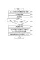
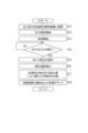
- FIG. 2 is a flow chart reporting potential leakage outside the target tissue during drug administration using the medical system of FIG. 1;
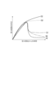
- FIG. 7 is a graph showing multiple patterns of changes in pressure detected by a pressure detection unit when a drug is administered in the medical system according to the first embodiment.
- FIG. 4 is a diagram showing how an injection needle that constitutes the medical system is punctured into a target tissue such as a tumor site.
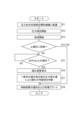
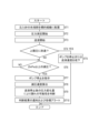
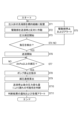
- FIG. 10 is a flowchart for notifying the possibility of drug leakage to the outside of the target tissue during drug administration using the medical system according to Modification 1 of the first embodiment;
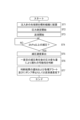
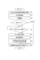
- FIG. 10 is a flow chart for notifying the possibility of drug leakage to the outside of the target tissue during drug administration using the medical system according to Modification 2 of the first embodiment;
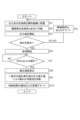
- FIG. FIG. 10 is a flowchart for notifying the possibility of drug leakage to the outside of the target tissue during drug administration using the medical system according to Modification 3 of the first embodiment;
- FIG. 10 is a flowchart for notifying the possibility of leakage of a drug to the outside of the target tissue during drug administration using the medical system according to Modification 4 of the first embodiment;
- FIG. FIG. 10 is a flowchart for notifying the possibility of leakage of a drug to the outside of the target tissue during drug administration using the medical system according to Modification 5 of the first embodiment;
- FIG. 10 is a flow chart for notifying the possibility of leakage outside the target tissue during drug administration by the medical system according to the second embodiment
- FIG. 9 is a graph showing a plurality of patterns of changes in pressure detected by a pressure detection unit when a medicine is administered in the medical system according to the second embodiment
- FIG. 10 is a flow chart for notifying the possibility of drug leakage to the outside of the target tissue during drug administration using the medical system according to Modification 1 of the second embodiment
- FIG. FIG. 10 is a flow chart for notifying the possibility of drug leakage to the outside of the target tissue during drug administration using the medical system according to Modification 2 of the second embodiment
- FIG. 10 is a flowchart for notifying the possibility of drug leakage to the outside of the target tissue during drug administration using the medical system according to Modification 3 of the second embodiment;
- FIG. 10 is a flowchart for notifying the possibility of drug leakage to the outside of the target tissue during drug administration using the medical system according to Modification 4 of the second embodiment;
- FIG. 10 is a flowchart for notifying the possibility of drug leakage to the outside of the target tissue during drug administration using the medical system according to Modification 5 of the second embodiment;
- FIG. 1 is a schematic diagram showing a medical system 1 according to the first embodiment.
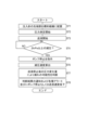
- FIG. 2 is a flow chart for notifying the possibility of drug leakage outside the target tissue during drug administration using the medical system 1 .
- FIG. 3 is a graph showing a plurality of patterns of changes in pressure detected by the pressure sensor 50 when medicine is administered in the medical system 1 .
- FIG. 4 is a diagram showing the injection needle 10 that constitutes the medical system 1 when the target tissue T is punctured.
- Tumor tissue The medical system 1 according to this embodiment can be used, for example, when administering a drug such as an anticancer drug to a target tissue T such as a patient's tumor tissue, as shown in FIG.
- Tumor tissue (target tissue T) to which a drug such as an anticancer agent is directly administered in this embodiment includes cancer tissue. That is, the medical system 1 according to this embodiment can be used for cancer treatment or prevention.
- the tumor is preferably a solid cancer because the injection needle 10 of the medical system 1 described later can easily access the tumor directly and easily administer the anticancer drug.
- Solid tumors include hepatocellular carcinoma, colorectal cancer, rectal cancer, colon cancer, breast cancer, esophageal cancer, gastric cancer, bile duct cancer, pancreatic cancer, malignant melanoma, non-small cell lung cancer, and small cell cancer.
- Lung cancer, head and neck cancer eg oral cavity cancer, nasopharyngeal cancer, oropharyngeal cancer, hypopharyngeal cancer, laryngeal cancer, salivary gland cancer and tongue cancer
- renal cell carcinoma eg clear renal cell carcinoma
- ovarian cancer e.g., serous ovarian cancer and ovarian clear cell adenocarcinoma
- nasopharyngeal cancer uterine cancer (e.g., cervical cancer and endometrial cancer)
- Anal cancer eg, anal canal cancer
- urothelial cancer eg, bladder cancer, upper urinary tract cancer, ureter cancer, renal pelvic cancer, and urethral cancer
- prostate cancer fallopian tube cancer
- primary peritoneal cancer malignant pleural mesothelioma
- gallbladder cancer biliary tract cancer
- biliary tract cancer eg, uveal melanoma and Merkel cell carcinoma
- testi
- the medical system 1 is outlined with reference to FIG. , a notification unit 90 , and a control unit 110 .
- the medical system 1 is connected to a liquid transfer pump Lt (corresponding to a drive unit).
- Lt liquid transfer pump
- the inner cylinder 20 and the tube 60 correspond to tubular members
- the control section 110 corresponds to the determination section/flow control section
- the measurement section 70 corresponds to the flow rate measurement section
- the measurement section 80 corresponds to the current measurement section. Equivalent to. Details will be described below.
- the injection needle 10 is configured to be able to pierce a target tissue T such as a tumor site, and is configured to allow distribution of drugs including anticancer agents such as doxorubicin and paclitaxel.
- the injection needle 10 is made of metal or the like, and has a sharp tip so that it can puncture the target tissue.
- the injection needle 10 is formed in an elongated shape, and includes a flow channel for circulating the drug inside so that the drug can be administered to the target tissue T, and a hole for allowing the drug to flow out from the flow channel.
- the hole of the injection needle 10 is provided so as to open toward the distal end side (right side in FIG. 4) at the distal end portion in the longitudinal direction.
- the hole is provided in the vicinity of the distal end so as to face the radial direction or the radial direction from the outer surface, and the hole is formed in at least one of the circumferential direction and the axial direction. may be arranged side by side.
- the injection needle 10 may be formed so as to extend straight when no external force is applied, or may be formed so as to be curved when no load is applied.
- the inner cylinder 20 is connected to the proximal end portion of the injection needle 10 and has an internal space 21 as a flow path for circulating the drug toward the injection needle 10 .
- a pressure sensor 50 which will be described later, is installed in the internal space 21 of the inner cylinder 20.
- a tube 60 is configured to be connectable to the inner cylinder 20 , so that the medicine sent from the liquid-sending pump Lt can be circulated in the inner space 21 of the inner cylinder 20 .
- the cannula 30 is arranged radially outward of the injection needle 10 and configured to be relatively movable in the longitudinal direction of the injection needle 10 .
- the outer cylinder 40 is integrally formed with the cannula 30, and is configured so that the inner cylinder 20 can be accommodated therein.
- the outer surface of at least one of the injection needle 10 and the cannula 30 may be provided with unevenness in order to improve visibility in visualization by an image diagnostic apparatus.
- the pressure sensor 50 is installed in the internal space 21 of the inner cylinder 20 and configured to be able to measure the pressure when the drug is being circulated from the liquid-sending pump Lt to the injection needle 10 .
- the specific configuration of the pressure sensor 50 is not particularly limited as long as it can measure the pressure of the drug passing through the internal space 21 of the inner cylinder 20, but an example is a diaphragm sensor.
- the pressure sensor 50 is installed in the internal space 21 of the inner cylinder 20 in this embodiment, the installation location of the pressure sensor is not limited to the internal space of the inner cylinder, and can be any of the administration routes in the medical system 1. may be the location of
- the tube 60 forms a flow path through which the drug delivered from the liquid delivery pump Lt is circulated toward the injection needle 10 .
- the tube 60 is configured to connect the liquid transfer pump Lt and the inner cylinder 20 in this embodiment.
- Tube 60 may be constructed from any known flexible plastic material.
- a known valve or the like can be installed in the tube 60 for switching ON/OFF of the flow of liquid feeding.
- the pressure sensor 50 may be installed in the inner space of the tube 60 as well as the inner space 21 of the inner cylinder 20 .
- the measurement unit 70 is installed at any position on the tube 60 and is configured to be able to measure the flow velocity of the medicine flowing through the channel of the tube 60 .
- the measurement unit 70 is not particularly limited as long as it can measure the flow velocity of the drug in the channel through which the drug flows.
- the flow velocity can be measured from the phase difference of the ultrasonic waves by the configuration of the ultrasonic wave transmitting device and the ultrasonic wave receiving device.
- the measurement unit 80 is configured to be able to measure the current value of the motor Lt3 of the liquid transfer pump Lt, which will be described later.
- the specific configuration of the measurement unit 80 is not particularly limited as long as it can measure the current value of the motor Lt3.
- a known ammeter can be used for the measuring unit 80 .
- the notification unit 90 is configured to be able to notify the user of the determination result of the control unit 110 . That is, the notification unit 90 notifies to stop the operation of the liquid feeding pump Lt when leakage is detected due to, for example, a drug being administered from the target tissue T in an amount exceeding the allowable amount.
- the notification unit 90 can adopt various notification methods as long as the determination result of the control unit 110 can be notified to the user.
- the notification items of the notification unit 90 include numerical display of the measured value of the pressure sensor 50, display of the measured value of the pressure sensor 50 in chronological graph form (see FIGS. 3 and 11), and text or text to inform the user. At least one of notification by voice or the like can be used.
- the control unit 110 includes processors such as CPU (Central Processing Unit) and GPU (Graphics Processing Unit), main storage such as memory, auxiliary storage such as HDD (Hard Disc Drive) and SSD (Solid State Drive).
- the control unit 110 is connected to the pressure sensor 50, the measurement units 70 and 80, the notification unit 90, and the liquid-sending pump Lt, and is configured to be able to control the operations of the liquid-sending pump Lt and the notification unit 90.
- the control unit 110 controls the liquid-sending pump Lt and the like so as to circulate the drug toward the injection needle 10 .
- the control unit 110 determines the possibility of leakage of the drug out of the target tissue (hereinafter simply referred to as “leakage possibility”) from the pressure behavior of the pressure sensor 50 after the pressure sensor 50 detects the decompression of the amount of change equal to or greater than the threshold. (sometimes referred to as “leakage possibility”)
- control unit 110 performs control so as to continue feeding the drug after the pressure sensor 50 detects a pressure reduction equal to or greater than the threshold.
- the possibility of leakage is judged from the pressure behavior in a state where the control unit 110 continues the control of the drug delivery after the first occurrence of depressurization.
- the control unit 110 also determines the possibility of leakage from at least one of the measurement units 70 and 80 in addition to the detection result by the pressure sensor 50 . Details will be described later.
- the liquid-sending pump Lt is connected to the medical system 1 and configured to circulate the drug toward the injection needle 10 .
- the liquid-sending pump Lt includes a syringe Lt1, a plunger Lt2, and a motor Lt3, as shown in FIG.
- the syringe Lt1 is provided with an internal space for containing a drug, and is configured so that a pusher Lt2 can be inserted from the base end side, and a tube 60 can be connected to the tip end side.
- the syringe Lt1 can be configured similarly to the inner cylinder 20 and the like.
- the plunger Lt2 is configured to be liquid-tightly movable (slidable) while being housed in the internal space of the syringe Lt1. As a result, when the syringe Lt1 is moved in the direction of decreasing the internal space, the medicine can be delivered toward the injection needle 10 through the tube 60 and the inner cylinder 20 .
- the motor Lt3 is connected to the plunger Lt2 and generates a driving force that moves the plunger Lt2 so that the internal space of the syringe Lt1 changes.
- the liquid-sending pump Lt generates a driving force for circulating the drug toward the injection needle 10 by driving the motor Lt3 in this embodiment.
- the motor Lt3 can rotate in either direction to move the pusher Lt2 in the direction of liquid transfer.
- the negative pressure can be detected by the pressure sensor 50 if the tip of the injection needle 10 is punctured into the target tissue T such as a tumor, while the blood vessel is not punctured. If so, the pressure sensor 50 will not measure negative pressure. This makes it possible to confirm whether the injection needle 10 has punctured the target tissue T or whether it has punctured a site other than the target tissue T, such as a blood vessel.
- the operator connects the tube 60 to the inner cylinder 20 and the liquid transfer pump Lt. Then, in a state in which the injection needle 10 does not puncture the target tissue T, the liquid feeding pump Lt is operated to circulate the drug through the internal space of the tube 60 and the internal space 21 of the inner cylinder 20 into the internal space of the injection needle 10 for priming. perform an operation.
- the purpose of the drug is to administer it to the target tissue T such as a tumor, and sufficient care should be taken in handling the drug that may flow out from the tip of the injection needle 10 during priming.
- the operator forms a small incision around the patient's abdomen and moves the tip of the injection needle 10 to the vicinity of the target tissue T (ST1).
- the operator pierces the target tissue T with the tip of the injection needle 10 as shown in FIG. 4 and starts pressure measurement by the pressure sensor 50 (ST2).
- the operator operates the liquid-sending pump Lt to administer the drug to the patient through the injection needle 10 (ST3).
- the drug is administered in excess of the allowable amount of the target tissue T. It was found that the measured value of the pressure sensor 50 decreased by a certain value or more when An example of the decrease value of the pressure measurement value is a reduction in pressure of 2 kPa or more per minute. If no decompression occurs (ST4: NO, see lines D1 and E1 in FIG. 3), there is no particular problem with leakage from the target tissue T, and the controller 110 determines that decompression will occur before the end of the procedure. or continue checking. If no leakage from the target tissue T is confirmed during the procedure, the end of the liquid delivery can be determined at the operator's discretion.
- the control unit 110 sets the pressure measurement result after the first pressure reduction by the pressure sensor 50 as the pressure behavior, and further calculates the amount of pressure change over time. Confirm (ST5). In the present embodiment, the control unit 110 acquires the pressure behavior for 10 to 120 seconds after the pressure reduction occurs for the first time by the pressure sensor 50 .
- control unit 110 determines from the pressure behavior that there is a high possibility of leakage outside the target tissue (ST6), The notification unit 90 is made to notify the determination result (ST7).
- the control unit 110 determines that the pressure after pressure reduction is maintained (ST6),
- the notification unit 90 is caused to notify that there is a possibility of leakage to the outside of the target tissue (ST7).
- “maintaining" the detected (measured) pressure value means that when the value measured by the pressure sensor 50 is displayed numerically on the display or the like in the notification unit 90, the range of digits that can be displayed is means that the data (numerical value) has not changed.
- the phrase "there is a possibility of leakage” here means that although there is a possibility of leakage, the possibility of leakage is lower than in the case where a further reduction in pressure is confirmed after the occurrence of the first reduction in pressure.
- the control unit 110 determines that there is no possibility of leakage. (ST6), and the notification unit 90 is notified of this (ST7).
- the control unit 110 determines the above-described possibility of leakage while considering the measurement results of the measurement units 70 and 80 . Specifically, if the flow velocity measured by the measuring unit 70 is higher than a predetermined value or the current value measured by the measuring unit 80 is lower than a predetermined value, the control unit 110 determines that the possibility of leakage increases. can do.
- the possibility of leakage can be judged to be low.
- drug delivery is continued even when there is a possibility of leakage.
- the medical system 1 has the injection needle 10, the inner cylinder 20, the pressure sensor 50, the control section 110, and the notification section 90.
- the injection needle 10 is configured to be able to be punctured so that the drug can be distributed.
- the inner cylinder 20 is connected to the injection needle 10 and configured to include an internal space 21 through which the drug is circulated toward the injection needle 10 .
- the pressure sensor 50 is installed in the internal space 21 of the inner cylinder 20 and configured to be able to measure the pressure when the drug is being distributed through the injection needle 10 .
- the control unit 110 determines the possibility of leakage of the drug to the outside of the target tissue from the pressure behavior detected by the pressure sensor 50 after the pressure sensor 50 detects the decompression of the amount of change equal to or greater than the threshold.
- the notification unit 90 is configured to be able to notify the user of the determination result of the control unit 110 .
- drugs such as anti-cancer drugs may leak out of the tumor before the prescribed amount is administered into the tumor.
- drugs such as anti-cancer drugs may leak out of the tumor before the prescribed amount is administered into the tumor.
- the drug flows from the blood vessels in the tumor into the bloodstream, or the drug leaks from the periphery of the tumor into the surrounding tissue.
- the amount of drug accumulated in the tumor may decrease, resulting in reduced drug efficacy, and increased systemic exposure, resulting in increased side effects.
- the medical system 1 determines the possibility of leakage from the subsequent pressure behavior triggered by the decompression in the channel during administration of the drug into the target tissue as described above. By configuring in this way, it is possible to notify a user such as an operator of information regarding omission of drug administration from the target tissue T such as a tumor site. Since the user can know the occurrence of leakage to the outside of the tumor during administration, the user can receive the above information and stop the drug delivery to prevent or suppress the outflow and exposure of the drug to the outside of the tumor. In addition, by re-administering the remaining drug to another site after detecting leakage to the outside of the tumor, it is possible to increase the amount of drug accumulated in the tumor and improve its efficacy.
- control unit 110 controls the liquid transfer pump Lt and the like so that the drug is circulated toward the injection needle 10 .
- the control unit 110 controls the liquid-sending pump Lt so as to continue the liquid-sending of the drug after the pressure sensor 50 detects the first reduction in pressure.
- the possibility of leakage is determined from the pressure behavior in a state in which the control unit 110 continues to deliver the medicine after the first pressure reduction.
- the notification unit 90 notifies that there is a high possibility of leakage when the pressure sensor 50 detects further pressure reduction after the occurrence of pressure reduction. If further decompression is confirmed after decompression, there is a high possibility that the drug accumulated in the tumor or the like has migrated from the tumor to another site. Therefore, the outflow and exposure of the drug to the outside of the tumor can be prevented or suppressed by notifying as described above.
- the notification unit 90 detects that there is a possibility of leakage, but further pressure reduction occurs after the first pressure reduction. Notifies you that the leak is less likely. If the pressure detected after decompression is maintained, extratumoral leakage would be less significant than with further decompression as described above. Therefore, by notifying as described above, it is possible to prevent or suppress the outflow and exposure of the drug outside the tumor while making the user aware of the degree of leakage of the drug outside the tumor.
- the notification unit 90 notifies that there is no possibility of leakage. If a depressurization is detected but the pressure rises thereafter, it is considered unlikely that a leak has occurred. Therefore, by notifying in this way, the user can be made to decide whether or not to continue administering the drug.
- the medical system 1 also has measurement units 70 and 80 .
- the measurement unit 70 is configured to be able to measure the flow velocity of the medicine flowing through the channel.
- the measurement unit 80 is configured to be able to measure the current value of the motor Lt3 that constitutes the liquid transfer pump Lt.
- the control unit 110 determines the possibility of leakage from the detection result of at least one of the measurement units 70 and 80 in addition to the detection result of the pressure sensor 50 . By referring to the measurement results of the measurement unit 70 and the measurement unit 80 in this way and confirming that the same tendency or the like as that of the pressure sensor 50 is shown, it is possible to determine the possibility of leakage occurring in the target tissue T such as a tumor. can improve the accuracy of
- FIG. 5 is a flowchart for notifying the possibility of drug leakage to the outside of the target tissue during drug administration using the medical system according to Modification 1 of the first embodiment.
- the medical system according to Modification 1 starts pressure measurement in order to notify the possibility of leakage from the target tissue T, and sets the upper limit value of the detection result by the pressure sensor 50 when the drug delivery is started. In this case, the following operations may be performed. Note that the medical system according to the following modification differs from the first embodiment in operations described later in the control unit 110, the notification unit 90, and the liquid feeding pump Lt, and the rest is the same as in the first embodiment. A description common to the form is omitted.
- ST1 to ST3 in the flowchart of FIG. 5 are the same as ST1 to ST3 in the flowchart of FIG.
- the control unit 110 detects that the pressure detected by the pressure sensor 50 exceeds the upper limit pressure XkPa (X is an arbitrary numerical value and corresponds to a fourth threshold value) after starting the liquid transfer of the drug from the injection needle 10 by the liquid transfer pump Lt. (ST4).
- XkPa is an arbitrary numerical value and corresponds to a fourth threshold value
- the control unit 110 notifies the operator that the detected pressure of the pressure sensor 50 has exceeded the upper limit value by means of character/numerical display, voice, or the like (ST8).
- the subsequent operations are the same as in the first embodiment, and the operations ST5 to ST8 in FIG. 5 are the same as those in ST4 to ST7 in FIG. correspond to each other. That is, the control unit 110 indicates to the notification unit 90 based on the amount of change in pressure after the first depressurization that there is a high possibility of leakage, or if there is a possibility of leakage but further depressurization is detected after the first depressurization. The user is notified that it is lower than or that there is no possibility of leakage (ST8).
- FIG. 6 is a flowchart for notifying the possibility of drug leakage to the outside of the target tissue during drug administration using the medical system according to Modification 2 of the first embodiment.
- ST1 to ST3 in the flowchart of FIG. 6 are the same as ST1 to ST3 in the flowchart of FIG. 2, respectively.
- the control unit 110 determines whether or not the pressure detected by the pressure sensor 50 exceeds the upper limit pressure XkPa (fourth threshold value) in the same manner as in the first modification ( ST4).
- the control unit 110 controls the liquid-sending pump Lt to stop the operation of the liquid-sending pump Lt, or increases the liquid-sending speed of the liquid-sending pump Lt. is controlled so as to reduce the liquid feed pump Lt (ST5). If the pressure detected by the pressure sensor 50 does not exceed the upper limit value (ST4: NO), the subsequent operations are the same as in the first embodiment, and the operations ST6 to ST9 in FIG. 6 are the same as those in ST4 to ST7 in FIG. correspond to each other.
- control unit 110 detects a high possibility of leakage or a further decrease in pressure after the first decrease in pressure to the notification unit 90 according to the amount of change in pressure after the first decrease in pressure. It is notified that it is lower than the case where the leakage occurs, or that there is no possibility of leakage (ST9).
- FIG. 7 is a flow chart explaining a method of notifying the possibility of omission of drug administration to the outside of the target tissue by the medical system according to Modification 3 of the first embodiment.
- ST1 to ST3 in the flowchart of FIG. 7 are respectively the same as ST1 to ST3 in the flowchart of FIG.
- the control unit 110 causes the notification unit 90 to make a notification related to inappropriate drug administration.
- the constant value (corresponding to the third threshold value) within a predetermined period of time can be specifically set such that the internal pressure does not exceed 3 kPa one minute after the start of administration.
- the subsequent operations are the same as in the first embodiment, and the operations of ST5 to ST8 in FIG. 7 are the same as in ST4 in FIG. to ST7, respectively. That is, the control unit 110 detects a high possibility of leakage or a further decrease in pressure after the first decrease in pressure to the notification unit 90 according to the amount of change in pressure after the first decrease in pressure. It is notified that it is lower than the case where the leakage occurs, or that there is no possibility of leakage (ST8).
- the notification unit 90 detects the drug when the value detected by the pressure sensor 50 does not exceed the third threshold value within a predetermined period of time after the controller 110 controls the start of feeding of the drug. to provide notifications related to improper administration of Depending on the position of the injection needle 10, the drug may be injected into a blood vessel or the like inside the tumor against the user's intention. Therefore, by configuring as described above based on the detection result of the pressure sensor 50, it can be detected that the drug is being administered to a site such as a blood vessel inside the tumor that may cause leakage to the outside of the tumor.
- FIG. 8 is a flowchart for explaining a method of notifying the possibility of drug leakage to the outside of the target tissue during drug administration by the medical system according to Modification 4 of the first embodiment.
- the control section 110 instructs the notification section 90 to stop the liquid feeding pump Lt. It was explained that notification should be made (ST7).
- control unit 110 stops the operation of the liquid feeding pump Lt instead of the operation of ST7 in FIG. Control may be performed to lower the rate than before the notification (ST7). Note that the operations from ST1 to ST6 in the flowchart of FIG. 8 are the same as those from ST1 to ST6 in FIG.
- control unit 110 performs control to stop the liquid transfer by the liquid transfer pump Lt when a pressure reduction equal to or greater than the threshold is detected, or control to reduce the liquid transfer speed of the liquid transfer pump Lt. I do.
- FIG. 9 is a flowchart for notifying the possibility of drug leakage to the outside of the target tissue during drug administration using the medical system according to Modification 5 of the first embodiment.
- the injection needle 10 explained that in some cases, the drug can be administered in a state in which the tip is punctured not in the tumor but in a nearby blood vessel or the like.
- the medical system according to Modification 5 may be configured such that it can be confirmed that the tip of the injection needle has not been punctured into a site other than the target tissue T, as described below. Note that ST1 in the flowchart of FIG. 9 is the same as ST1 in FIG.
- the motor Lt3 that constitutes the liquid feeding pump Lt can be configured to be rotatable in the forward direction for feeding the drug toward the injection needle 10 and the reverse direction opposite to the forward direction.
- the control unit 110 controls the liquid transfer pump Lt so that it can rotate not only in the forward direction but also in the forward and reverse directions.
- the pressure sensor 50 detects fluid in the flow path when the motor Lt3 is reversely rotated while the tip of the injection needle 10 is placed on a solid site such as a tumor. It is configured to be able to detect negative pressure.
- control unit 110 After the tip of the injection needle 10 is placed in the vicinity of the target tissue T, the control unit 110 automatically feeds liquid by the operation of the operator or by a program or the like stored in the control unit 110. (ST2). Then, the control unit 110 starts detection by the pressure sensor 50 (ST3), and confirms whether or not the detected value is a negative pressure (ST4).
- the tip of the injection needle 10 may be positioned inside a blood vessel instead of the target tissue T such as a tumor.
- the control unit 110 stops the liquid feeding pump Lt and notifies the notification unit 90 that the tip of the injection needle 10 is not properly placed (ST5).
- the control unit 110 sends a message to the notification unit 90 such as "There is a possibility that the injection needle is not stuck in the target tissue such as a tumor. Please check the positional relationship between the tip of the injection needle and the target tissue.” Notification can be made by character display or voice.
- control unit 110 detects a high possibility of leakage or a further decrease in pressure after the first decrease in pressure to the notification unit 90 according to the amount of change in pressure after the first decrease in pressure. It is notified that it is lower than the case where the leakage occurs, or that there is no possibility of leakage (ST10).
- the pressure sensor 50 detects that the flow path of the inner cylinder 20 and the like becomes negative pressure when the motor Lt3 of the liquid feeding pump Lt rotates in the second direction opposite to the first direction in which the medicine is fed. It is configured so that it can be detected. If the tip of the injection needle 10 is positioned inside the blood vessel, the injection needle 10 performs a suction-like operation to suck blood, and the pressure sensor 50 does not show a negative pressure. On the other hand, if the tip of the injection needle 10 is positioned inside a solid tissue such as a tumor, the pressure sensor 50 will give a negative pressure. In this way, it is possible to check for leakage after confirming that the tip of the injection needle 10 is properly punctured into the target tissue T based on the rotation of the motor Lt3 and the measurement value of the pressure sensor 50.
- FIG. 10 is a flowchart for notifying the possibility of leakage of the drug to the outside of the target tissue during drug administration by the medical system according to the second embodiment
- FIG. 4 is a graph showing changes in pressure over time when detecting drug leakage.
- control unit 110 continues the liquid transfer of the liquid transfer pump Lt even when the pressure reduction is detected for the first time from the start of the liquid transfer.
- control unit 110 may perform the following control when the pressure sensor 50 detects the pressure reduction.
- the configuration of the medical system is the same as that of the first embodiment, and the control method of the control unit 110 and the operation of the liquid transfer pump Lt are different from those of the first embodiment. . Further, the operations from ST1 to ST3 in the flow chart for notifying the possibility of leakage to the outside of the target tissue of the medical system according to this embodiment are the same as ST1 to ST3 in the flow chart of FIG. 2, so description thereof will be omitted.
- the control section 110 causes the notification section 90 to notify the stop of the liquid feeding pump Lt by means of character display, voice, or the like (ST5). Then, the control unit 110 instructs the liquid-sending pump Lt to stop, and confirms the pressure behavior of the channel when the liquid-sending is stopped. Alternatively, when the liquid transfer pump Lt is stopped by the operator or the like, the control unit 110 confirms the pressure behavior of the channel when the liquid transfer is stopped. That is, the control section 110 confirms the pressure change within the predetermined time (ST6). Then, the control unit 110 confirms whether a rapid decompression is detected after the liquid supply is stopped.
- the rapid pressure reduction pressure behavior means, for example, a pressure reduction with a pressure change amount of 6.0 kPa (corresponding to the second threshold value) or more per minute.
- control unit 110 determines the possibility of leakage based on the pressure behavior after the liquid supply of the medicine is stopped. After the occurrence of the first decompression and after confirming the stop of the liquid transfer based on the measurement value of the pressure sensor 50, when further decompression equal to or greater than the second threshold is detected (line A2 in FIG. 11), the control unit 110 (ST7). Then, the control unit 110 causes the notification unit 90 to notify that there is a high possibility of leakage by character display, voice, or the like, as in the first embodiment (ST8).
- the controller 110 determines that the amount of depressurization change It is determined that the possibility of leakage is lower than in the case of the second threshold value or more (ST7). Then, the control section 110 causes the notification section 90 to notify that effect (ST8).
- the control unit 110 determines that there is no possibility of leakage. (ST7). Then, the control section 110 causes the notification section 90 to notify that there is no possibility of omission (ST8).
- the possibility of leakage is determined by considering the measurement results of the measurement units 70 and 80 in addition to the measurement value of the pressure sensor 50, as in the first embodiment.
- the medical system is configured so that the notification unit 90 performs at least one of display of characters, etc., and voice notification to urge the user to stop liquid feeding by the liquid feeding pump Lt. Then, when the pressure reduction equal to or greater than the threshold value is detected for the first time, the notification unit 90 instructs (notifies) the user to stop the liquid transfer of the liquid chemical by the liquid transfer pump Lt.
- the possibility of drug leakage is determined from the pressure behavior after the liquid supply of the drug is stopped. In this way, it is possible to determine whether or not the drug leaks from the target tissue T based on the pressure behavior of the pressure sensor 50 after the first occurrence of decompression.
- the notification unit 90 notifies that there is a high possibility of leakage when the pressure sensor 50 detects a further decrease in pressure equal to or greater than the second threshold after the first decrease in pressure. It can be considered that the pressure in the channel does not decrease unless the drug leaks from the target tissue T after the first decompression is confirmed and the liquid transfer by the liquid transfer pump Lt is stopped. Therefore, by detecting such a pressure value after the liquid supply is stopped, it is possible to determine drug leakage from the target tissue T and notify the user of the fact.
- the notification unit 90 detects further pressure reduction by the pressure sensor 50 after the occurrence of the first pressure reduction, and if the detected value is less than the second threshold, there is a possibility of leakage. Notifies you that the leak is less likely. If the liquid-sending pump Lt is stopped after the first occurrence of reduced pressure and no leakage occurs, it is unlikely that the pressure in the flow path will decrease. Therefore, it is possible to determine that the possibility of leakage is relatively low by confirming that the amount of pressure change after the liquid supply is stopped is less than the second threshold value, and to notify the user of this fact.
- the notification unit 90 notifies that there is no possibility of leakage when the detection value detected by the pressure sensor 50 is maintained from the value after the occurrence of the first pressure reduction. It is almost impossible to consider the possibility that the target tissue T is leaking from the fact that the decompression does not occur after the first decompression occurs. Therefore, by notifying the user of the above content, it is possible to prompt the user to resume drug administration to the target tissue T such as a tumor.
- FIGS. 12 to 16 are flow charts for notifying the possibility of leakage of the drug to the outside of the target tissue when administering the drug using the medical system according to the modified example of the second embodiment.
- Modifications 1 to 5 have been described in the first embodiment in which liquid transfer is continued after the first occurrence of reduced pressure. Operations similar to those of Modifications 1 to 5 can be performed.
- the control unit 110 controls the pressure after stopping the liquid feeding as in the second embodiment. is confirmed (ST7). Then, similarly to the second embodiment, the control unit 110 informs the notification unit 90 according to the pressure behavior after the liquid supply is stopped that there is a high possibility of leakage, that there is a possibility of leakage, but the pressure change after the first pressure reduction. It is notified that the amount is lower than the second threshold value or more, or that there is no possibility of leakage (ST9).
- ST6 to ST10 when ST4 is NO in FIG. 13 are the same as ST4 to ST8 in FIG. That is, the control unit 110 stops the liquid transfer pump Lt after confirming the pressure reduction for the first time. Then, the control unit 110 determines that there is a high possibility of leakage depending on the pressure behavior after the liquid supply is stopped, that there is a possibility of leakage, but is lower than the case where the pressure change amount after the first pressure reduction is equal to or greater than the second threshold, Alternatively, the notification unit 90 is notified that there is no possibility of omission (ST10).
- the notification by the notification unit 90 in ST9 when proceeding to ST1 to ST4 in FIG. 14 and ST4 is YES is the same as the notification by the notification unit 90 in ST8 when proceeding to ST1 to ST4 in FIG. 7 and ST4 is YES.
- the operations of ST5 to ST9 when ST4 of FIG. 14 is NO are the same as the operations of ST4 to ST8 of FIG.
- control unit 110 causes the notification unit 90 to cause the leakage to occur as in the fourth modification of the first embodiment. may be controlled to stop the liquid feed pump Lt when the notification regarding the possibility of Further, the control section 110 may perform control to decrease the liquid feeding speed of the liquid feeding pump Lt instead of the control to stop the liquid feeding pump Lt (ST8).
- control unit 110 continues the operation of the liquid feeding pump Lt when confirming the first pressure reduction
- control unit 110 continues the operation of the liquid feeding pump Lt after confirming the first pressure reduction
- the notification unit 90 is controlled to instruct to stop the operation of the
- the present invention is not limited to this, and the control unit 110 is configured to switch the liquid feeding operation of the liquid feeding pump Lt from continuation to stop or vice versa after the occurrence of the first pressure reduction triggered by a predetermined input. good too.
- a signal from the liquid-sending pump Lt or the flow velocity of the internal space 21 of the inner cylinder 20 by the measurement unit 70 can be cited as an input for switching the operation of the liquid-sending pump Lt after the first occurrence of depressurization.
- the notification unit 90 notifies the possibility of leakage by using characters/graph display and sound on the display. Notification may be performed using light or vibration.
- control unit 110 determines leakage from the target tissue T based on the measurement results of the measurement units 70 and 80 in addition to the detection results of the pressure sensor 50 .
- the medical system may determine the possibility of leakage from the target tissue T from the detection result of the pressure sensor 50 without including the measurement units 70 and 80 .
- infusion needle 10 infusion needle, 20 inner cylinder (tubular member), 30 cannulas, 40 outer cylinder, 50 pressure sensor (pressure detection unit), 60 tube (tubular member), 70 measurement unit (flow velocity measurement unit), 80 measurement unit (current measurement unit), 90 notification unit; 110 control unit (judgment unit, distribution control unit), Lt liquid feed pump.
- pressure sensor pressure detection unit
- 60 tube tubular member
- 70 measurement unit flow velocity measurement unit
- 80 measurement unit current measurement unit
- 90 notification unit 110 control unit (judgment unit, distribution control unit), Lt liquid feed pump.
Landscapes
- Health & Medical Sciences (AREA)
- Vascular Medicine (AREA)
- Engineering & Computer Science (AREA)
- Anesthesiology (AREA)
- Biomedical Technology (AREA)
- Heart & Thoracic Surgery (AREA)
- Hematology (AREA)
- Life Sciences & Earth Sciences (AREA)
- Animal Behavior & Ethology (AREA)
- General Health & Medical Sciences (AREA)
- Public Health (AREA)
- Veterinary Medicine (AREA)
- Infusion, Injection, And Reservoir Apparatuses (AREA)
Abstract
【課題】腫瘍部位等の標的組織からの薬剤の投与漏れに関する情報を使用者に通知することを目的とする。 【解決手段】医療システム1は、穿刺可能に構成され薬剤を流通可能な注入針10と、注入針に接続され、注入針に向けて薬剤を流通させる流路21を含む内筒20と、流路に設置され注入針に薬剤を流通させている際の圧力を測定可能な圧力センサ50と、圧力センサによって閾値以上の変化量の減圧が検出された後の圧力センサの圧力挙動から薬剤の漏れの可能性を判断する制御部110と、制御部の判断結果を使用者に通知する通知部90と、を有する。
Description
本発明は、医療システムに関する。
肝臓に形成された腫瘍を処置する場合、局所的に治療を施してがん細胞を壊死させる経皮的エタノール注入療法(例えば、特許文献1を参照)を行う場合がある。術者は、腹部や胸部を切開し、肝臓に針を穿刺して、針先を肝臓がんの患部へ到達させる。そして、針先からエタノールを注入することによって、がん細胞を壊死させることができる。
本発明者らは、針等の部材を用いて腫瘍部位を穿刺して薬剤を注入するような薬剤の組織内投与を行う際に、注入針が腫瘍に穿刺できなかったり、腫瘍に穿刺できても薬剤の投与量が多いなどにより、薬剤が腫瘍外に漏れ出したりすることに着目している。したがって、本発明は、腫瘍部位等の標的組織からの薬剤の投与漏れに関する情報を使用者に通知できる医療システムを提供することを目的とする。
本発明は、(1)注入針と、管状部材と、圧力検出部と、判断部と、通知部と、を有する医療システムである。注入針は、穿刺可能に構成され、薬剤を流通可能に構成している。管状部材は、少なくとも一部が注入針に接続され、注入針に向けて薬剤を流通させる流路を含む。圧力検出部は、管状部材の流路に設置され、注入針に薬剤を流通させている際の圧力を測定可能に構成している。判断部は、圧力検出部によって閾値以上の変化量の減圧が検出された後の圧力検出部の圧力挙動から標的組織外への薬剤の漏れの可能性を判断する。通知部は、判断部の判断結果を使用者に通知可能に構成している。
ここで、本発明の実施形態として、
(2)上記(1)の医療システムは、前記薬剤を前記注入針に向けて流通するように制御する流通制御部を有し、前記流通制御部は、前記圧力検出部によって前記減圧が検出された後に前記薬剤の送液を継続するように制御し、前記漏れの可能性は、前記減圧の発生後に前記流通制御部が前記薬剤の送液を継続する制御を行っている状態での圧力挙動から判断されることが好ましい。
(3)上記(2)の医療システムにおいて、前記通知部は、前記減圧の発生後に前記圧力検出部によってさらなる減圧を検出した場合に前記漏れの可能性が高いことを通知することが好ましい。
(4)上記(2)または(3)の医療システムにおいて、前記通知部は、前記圧力検出部によって前記減圧の発生後の値から維持された圧力を検出した場合、前記漏れの可能性があり、かつ、前記減圧の発生後にさらなる減圧を検出した場合よりも漏れの可能性が低いことを通知することが好ましい。
(5)上記(2)から(4)のいずれかの医療システムにおいて、前記通知部は、前記圧力検出部によって前記減圧の発生後の値から上昇した圧力を検出した場合、前記漏れの可能性がないことを通知することが好ましい。
(6)上記(1)の医療システムは、前記薬剤を前記注入針に向けて流通するように制御する流通制御部を有し、前記減圧が検出された際には、前記通知部は使用者に前記薬剤の送液を停止させるように通知を行う、または、前記流通制御部が前記薬剤の送液を停止するように制御を行い、前記漏れの可能性は、前記薬剤の送液停止後の圧力挙動から判断されることが好ましい。
(7)上記(6)の医療システムにおいて、前記通知部は、前記減圧の発生後に前記圧力検出部によってさらなる減圧が検出され、当該検出された減圧の変化量が第2閾値以上の場合に前記漏れの可能性が高いことを通知することが好ましい。
(8)上記(6)または(7)の医療システムにおいて、前記通知部は、前記減圧の発生後に前記圧力検出部によってさらなる減圧が検出され、当該検出された減圧の変化量が第2閾値未満の場合に前記漏れの可能性があり、かつ、前記漏れの可能性が前記減圧の変化量が第2閾値以上の場合より低いことを通知することが好ましい。
(9)上記(6)~(8)のいずれかの医療システムにおいて、前記通知部は、前記圧力検出部によって前記減圧の発生後の値から維持された圧力を検出した場合、前記漏れの可能性がないことを通知することが好ましい。
(10)上記(1)~(9)の医療システムは、前記薬剤を前記注入針に向けて流通するように制御する流通制御部を有し、前記通知部は、前記流通制御部による前記薬剤の送液を開始する制御以降であって所定時間以内に前記圧力検出部によって検出された圧力が第3閾値を超えない場合に前記薬剤の投与が適切にされていないことに関連する通知を行うことが好ましい。
(11)上記(1)~(10)の医療システムは前記薬剤を前記注入針に向けて流通するように制御する流通制御部を有し、前記通知部は、前記圧力検出部によって圧力が第4閾値を越えたことが検出された場合に通知を行う、または、前記流通制御部は、前記薬剤の送液を停止するように制御を行う、もしくは検出前よりも前記薬剤の送液速度を低くするように制御を行うことが好ましい。
(12)上記(1)~(10)のいずれかの医療システムは、前記薬剤を前記注入針に向けて流通するように制御を行う流通制御部を有し、前記流通制御部は、前記通知部によって前記漏れの可能性に関連する通知が行われる際に前記薬剤の送液を停止するように制御を行う、または通知前よりも前記薬剤の送液速度を低くするように制御を行うことが好ましい。
(13)上記(1)~(12)のいずれかの医療システムは前記薬剤を前記注入針に向けて流通するように制御を行う流通制御部を有し、前記流通制御部は、閾値以上の前記減圧が検出された際に前記薬剤の送液の継続および前記薬剤の送液の停止が切り替え可能であり、前記漏れの可能性は、前記減圧の発生後に前記流通制御部によって前記薬剤の送液を継続する制御を行った場合、前記漏れの可能性は前記減圧の発生後に前記流通制御部が前記薬剤の送液を継続する制御を行っている状態での圧力挙動から判断され、前記減圧の発生後に前記流通制御部が前記薬剤の送液を停止する制御を行った場合、前記漏れの可能性は前記薬剤の送液停止後の圧力挙動から判断されることが好ましい。
(14)上記(1)~(13)のいずれかの医療システムは第1方向への動作によって前記薬剤を前記注入針に向けて流通させる駆動力を生じさせ、かつ、前記第1方向と反対の第2方向に動作可能な駆動部を制御する流通制御部を有し、前記圧力検出部は、前記駆動部が前記第2方向に回転した際に前記流路が負圧になっていることを検出可能であることが好ましい。
(15)上記(1)~(14)のいずれかの医療システムは前記薬剤を前記注入針に向けて流通するように制御を行い、モーターの駆動によって前記薬剤を前記注入針に向けて流通させる駆動力を生じさせる駆動部を制御する流通制御部と、前記流路を流通する前記薬剤の流速を測定可能な流速測定部若しくは前記モーターの電流値を測定可能な電流測定部の少なくともいずれかと、を有し、前記判断部は、前記圧力検出部による検出結果に加えて前記流速測定部と前記電流測定部の少なくともいずれかの検出値から前記漏れの可能性を判断することが好ましい。
ここで、本発明の実施形態として、
(2)上記(1)の医療システムは、前記薬剤を前記注入針に向けて流通するように制御する流通制御部を有し、前記流通制御部は、前記圧力検出部によって前記減圧が検出された後に前記薬剤の送液を継続するように制御し、前記漏れの可能性は、前記減圧の発生後に前記流通制御部が前記薬剤の送液を継続する制御を行っている状態での圧力挙動から判断されることが好ましい。
(3)上記(2)の医療システムにおいて、前記通知部は、前記減圧の発生後に前記圧力検出部によってさらなる減圧を検出した場合に前記漏れの可能性が高いことを通知することが好ましい。
(4)上記(2)または(3)の医療システムにおいて、前記通知部は、前記圧力検出部によって前記減圧の発生後の値から維持された圧力を検出した場合、前記漏れの可能性があり、かつ、前記減圧の発生後にさらなる減圧を検出した場合よりも漏れの可能性が低いことを通知することが好ましい。
(5)上記(2)から(4)のいずれかの医療システムにおいて、前記通知部は、前記圧力検出部によって前記減圧の発生後の値から上昇した圧力を検出した場合、前記漏れの可能性がないことを通知することが好ましい。
(6)上記(1)の医療システムは、前記薬剤を前記注入針に向けて流通するように制御する流通制御部を有し、前記減圧が検出された際には、前記通知部は使用者に前記薬剤の送液を停止させるように通知を行う、または、前記流通制御部が前記薬剤の送液を停止するように制御を行い、前記漏れの可能性は、前記薬剤の送液停止後の圧力挙動から判断されることが好ましい。
(7)上記(6)の医療システムにおいて、前記通知部は、前記減圧の発生後に前記圧力検出部によってさらなる減圧が検出され、当該検出された減圧の変化量が第2閾値以上の場合に前記漏れの可能性が高いことを通知することが好ましい。
(8)上記(6)または(7)の医療システムにおいて、前記通知部は、前記減圧の発生後に前記圧力検出部によってさらなる減圧が検出され、当該検出された減圧の変化量が第2閾値未満の場合に前記漏れの可能性があり、かつ、前記漏れの可能性が前記減圧の変化量が第2閾値以上の場合より低いことを通知することが好ましい。
(9)上記(6)~(8)のいずれかの医療システムにおいて、前記通知部は、前記圧力検出部によって前記減圧の発生後の値から維持された圧力を検出した場合、前記漏れの可能性がないことを通知することが好ましい。
(10)上記(1)~(9)の医療システムは、前記薬剤を前記注入針に向けて流通するように制御する流通制御部を有し、前記通知部は、前記流通制御部による前記薬剤の送液を開始する制御以降であって所定時間以内に前記圧力検出部によって検出された圧力が第3閾値を超えない場合に前記薬剤の投与が適切にされていないことに関連する通知を行うことが好ましい。
(11)上記(1)~(10)の医療システムは前記薬剤を前記注入針に向けて流通するように制御する流通制御部を有し、前記通知部は、前記圧力検出部によって圧力が第4閾値を越えたことが検出された場合に通知を行う、または、前記流通制御部は、前記薬剤の送液を停止するように制御を行う、もしくは検出前よりも前記薬剤の送液速度を低くするように制御を行うことが好ましい。
(12)上記(1)~(10)のいずれかの医療システムは、前記薬剤を前記注入針に向けて流通するように制御を行う流通制御部を有し、前記流通制御部は、前記通知部によって前記漏れの可能性に関連する通知が行われる際に前記薬剤の送液を停止するように制御を行う、または通知前よりも前記薬剤の送液速度を低くするように制御を行うことが好ましい。
(13)上記(1)~(12)のいずれかの医療システムは前記薬剤を前記注入針に向けて流通するように制御を行う流通制御部を有し、前記流通制御部は、閾値以上の前記減圧が検出された際に前記薬剤の送液の継続および前記薬剤の送液の停止が切り替え可能であり、前記漏れの可能性は、前記減圧の発生後に前記流通制御部によって前記薬剤の送液を継続する制御を行った場合、前記漏れの可能性は前記減圧の発生後に前記流通制御部が前記薬剤の送液を継続する制御を行っている状態での圧力挙動から判断され、前記減圧の発生後に前記流通制御部が前記薬剤の送液を停止する制御を行った場合、前記漏れの可能性は前記薬剤の送液停止後の圧力挙動から判断されることが好ましい。
(14)上記(1)~(13)のいずれかの医療システムは第1方向への動作によって前記薬剤を前記注入針に向けて流通させる駆動力を生じさせ、かつ、前記第1方向と反対の第2方向に動作可能な駆動部を制御する流通制御部を有し、前記圧力検出部は、前記駆動部が前記第2方向に回転した際に前記流路が負圧になっていることを検出可能であることが好ましい。
(15)上記(1)~(14)のいずれかの医療システムは前記薬剤を前記注入針に向けて流通するように制御を行い、モーターの駆動によって前記薬剤を前記注入針に向けて流通させる駆動力を生じさせる駆動部を制御する流通制御部と、前記流路を流通する前記薬剤の流速を測定可能な流速測定部若しくは前記モーターの電流値を測定可能な電流測定部の少なくともいずれかと、を有し、前記判断部は、前記圧力検出部による検出結果に加えて前記流速測定部と前記電流測定部の少なくともいずれかの検出値から前記漏れの可能性を判断することが好ましい。
本発明によれば、腫瘍部位等の標的組織からの薬剤の投与漏れに関する情報を使用者に通知できる。
以下、本発明を実施するための形態について、図面を参照しながら詳細に説明する。ここで示す実施形態は、本発明の技術的思想を具体化するために例示するものであって、本発明を限定するものではない。また、本発明の要旨を逸脱しない範囲で当業者などにより考え得る実施可能な他の形態、実施例および運用技術などは全て本発明の範囲、要旨に含まれると共に、特許請求の範囲に記載された発明とその均等の範囲に含まれる。
さらに、本明細書に添付する図面は、図示と理解のしやすさの便宜上、適宜縮尺、縦横の寸法比、形状などについて、実物から変更し模式的に表現される場合があるが、あくまで一例であって、本発明の解釈を限定するものではない。
また、以下の説明において、「第1」、「第2」のような序数詞を付して説明するが、特に言及しない限り、便宜上用いるものであって何らかの順序を規定するものではない。
(第1実施形態)
以下、図1から図4を参照して第1実施形態に係る医療システム1について説明する。図1は第1実施形態に係る医療システム1を示す概略図である。図2は医療システム1を用いた薬剤投与の際の標的組織外への薬剤の漏れの可能性を通知するフローチャートである。図3は医療システム1にて薬剤投与を行った際の圧力センサ50によって検出される圧力の推移を複数パターン示すグラフである。図4は医療システム1を構成する注入針10を標的組織Tへ穿刺する際を示す図である。
以下、図1から図4を参照して第1実施形態に係る医療システム1について説明する。図1は第1実施形態に係る医療システム1を示す概略図である。図2は医療システム1を用いた薬剤投与の際の標的組織外への薬剤の漏れの可能性を通知するフローチャートである。図3は医療システム1にて薬剤投与を行った際の圧力センサ50によって検出される圧力の推移を複数パターン示すグラフである。図4は医療システム1を構成する注入針10を標的組織Tへ穿刺する際を示す図である。
(腫瘍組織)
本実施形態に係る医療システム1は、図4に示すように抗がん剤等の薬剤を患者の腫瘍組織等の標的組織Tに投与する際等に利用することができる。本実施形態において抗がん剤等の薬剤が直接投与される腫瘍組織(標的組織T)としては、がん組織が挙げられる。すなわち、本実施形態に係る医療システム1は、がん治療または予防のために使用され得る。後述する医療システム1の注入針10は腫瘍に直接アクセスしやすく、抗がん剤を投与しやすいことから、腫瘍は固形がんであることが好ましい。固形がんとしては、肝細胞がん、大腸がん、直腸がん、結腸がん、乳がん、食道がん、胃がん、胆管がん、膵臓がん、悪性黒色腫、非小細胞肺がん、小細胞肺がん、頭頸部がん(例えば、口腔がん、上咽頭がん、中咽頭がん、下咽頭がん、喉頭がん、唾液腺がんおよび舌がん)、腎細胞がん(例えば、淡明細胞型腎細胞がん)、卵巣がん(例えば、漿液性卵巣がんおよび卵巣明細胞腺がん)、鼻咽頭がん、子宮がん(例えば、子宮頸がんおよび子宮体がん)、肛門がん(例えば、肛門管がん)、食道胃接合部がん、尿路上皮がん(例えば、膀胱がん、上部尿路がん、尿管がん、腎盂がんおよび尿道がん)、前立腺がん、卵管がん、原発性腹膜がん、悪性胸膜中皮腫、胆嚢がん、胆道がん、皮膚がん(例えば、ブドウ膜悪性黒色腫およびメルケル細胞がん)、精巣がん(胚細胞腫瘍)、膣がん、外陰部がん、陰茎がん、小腸がん、内分泌系がん、甲状腺がん、副甲状腺がん、副腎がん、脊椎腫瘍、神経芽細胞腫、髄芽腫、眼網膜芽細胞腫、神経内分泌腫瘍、脳腫瘍(例えば、神経膠腫(例えば、神経膠芽腫および神経膠肉腫)および髄膜腫)および扁平上皮がんなどが挙げられる。一態様として、腫瘍は、乳がんや肝細胞がん、また肝転移した大腸がんなども含む。
本実施形態に係る医療システム1は、図4に示すように抗がん剤等の薬剤を患者の腫瘍組織等の標的組織Tに投与する際等に利用することができる。本実施形態において抗がん剤等の薬剤が直接投与される腫瘍組織(標的組織T)としては、がん組織が挙げられる。すなわち、本実施形態に係る医療システム1は、がん治療または予防のために使用され得る。後述する医療システム1の注入針10は腫瘍に直接アクセスしやすく、抗がん剤を投与しやすいことから、腫瘍は固形がんであることが好ましい。固形がんとしては、肝細胞がん、大腸がん、直腸がん、結腸がん、乳がん、食道がん、胃がん、胆管がん、膵臓がん、悪性黒色腫、非小細胞肺がん、小細胞肺がん、頭頸部がん(例えば、口腔がん、上咽頭がん、中咽頭がん、下咽頭がん、喉頭がん、唾液腺がんおよび舌がん)、腎細胞がん(例えば、淡明細胞型腎細胞がん)、卵巣がん(例えば、漿液性卵巣がんおよび卵巣明細胞腺がん)、鼻咽頭がん、子宮がん(例えば、子宮頸がんおよび子宮体がん)、肛門がん(例えば、肛門管がん)、食道胃接合部がん、尿路上皮がん(例えば、膀胱がん、上部尿路がん、尿管がん、腎盂がんおよび尿道がん)、前立腺がん、卵管がん、原発性腹膜がん、悪性胸膜中皮腫、胆嚢がん、胆道がん、皮膚がん(例えば、ブドウ膜悪性黒色腫およびメルケル細胞がん)、精巣がん(胚細胞腫瘍)、膣がん、外陰部がん、陰茎がん、小腸がん、内分泌系がん、甲状腺がん、副甲状腺がん、副腎がん、脊椎腫瘍、神経芽細胞腫、髄芽腫、眼網膜芽細胞腫、神経内分泌腫瘍、脳腫瘍(例えば、神経膠腫(例えば、神経膠芽腫および神経膠肉腫)および髄膜腫)および扁平上皮がんなどが挙げられる。一態様として、腫瘍は、乳がんや肝細胞がん、また肝転移した大腸がんなども含む。
図1を参照して医療システム1について概説すれば、注入針10と、内筒20と、カニューレ30と、外筒40と、圧力センサ50と、チューブ60と、測定部70と、測定部80と、通知部90と、制御部110と、を有する。医療システム1は、送液ポンプLt(駆動部に相当)に接続される。内筒20およびチューブ60は本明細書において管状部材に相当し、制御部110は判断部・流通制御部に相当し、測定部70は流速測定部に相当し、測定部80は電流測定部に相当する。以下、詳述する。
注入針10は、腫瘍部位等の標的組織Tに穿刺可能に構成され、ドキソルビシンやパクリタキセル等の抗がん剤を含む薬剤を流通可能に構成している。注入針10は金属等によって形成され、先端が標的組織に穿刺できるように鋭利に構成している。注入針10は、長尺状に形成され、薬剤を標的組織Tに投与できるように内部に薬剤を流通させる流路と、流路から薬剤を外部に流出させる穴部を備える。
本実施形態において注入針10の穴部は、長手方向における先端部において先端側(図4における右側)を向いて開口するように設けている。ただし、標的組織Tに薬剤を投与できれば、穴部は上記以外にも先端部の付近において外側面から放射方向又は径方向を向くように設け、当該穴部を周方向および軸方向の少なくともいずれかに複数並べて配置してもよい。また、注入針10は、外力をかけていない状態においてストレートに伸びるように形成してもよいし、無負荷状態で湾曲するように形成してもよい。
内筒20は、注入針10の基端部と接続され、薬剤を注入針10に向けて流通させる内部空間21を流路として設けている。内筒20の内部空間21には後述する圧力センサ50を設置するように構成している。内筒20にはチューブ60を接続可能に構成しており、これにより送液ポンプLtから送られる薬剤を内筒20の内部空間21に流通できる。
カニューレ30は、注入針10の径方向における外方に配置され、注入針10の長手方向に対して相対的に移動可能に構成している。外筒40はカニューレ30と一体に構成され、内筒20を内部に収容可能に構成している。なお、注入針10およびカニューレ30の少なくともいずれかの外表面には画像診断装置による可視化などにおける視認性を良好にするために凹凸を設けてもよい。
圧力センサ50は、内筒20の内部空間21に設置され、送液ポンプLtから注入針10に薬剤を流通させている際の圧力を測定可能に構成している。圧力センサ50は、内筒20の内部空間21を通過する薬剤の圧力を測定できれば具体的な構成は特に限定されないが、一例としてダイヤフラム式のセンサを挙げることができる。また、圧力センサ50は、本実施形態において内筒20の内部空間21に設置しているが、圧力センサの設置場所は内筒の内部空間に限定されず、医療システム1における投与経路のいずれかの場所であってもよい。
チューブ60は、送液ポンプLtから送出された薬剤を注入針10に向けて流通させる流路を形成している。チューブ60は、本実施形態において送液ポンプLtと内筒20を接続するように構成している。チューブ60は、可撓性のある公知のプラスチック材料から構成できる。また、チューブ60には、送液の流通のオンオフを切り替えるために公知のバルブ等を設置することができる。圧力センサ50は、内筒20の内部空間21以外にもチューブ60の内部空間等に設置してもよい。
測定部70は、チューブ60のいずれかの位置に設置されてチューブ60の流路を流通する薬剤の流速を測定可能に構成している。測定部70は、薬剤が流通する流路における薬剤の流速を測定できれば特に限定されない。測定部70について例示すれば、超音波の発信装置と、受信装置の構成によって超音波の位相差から流速を測定することができる。
測定部80は、後述する送液ポンプLtのモーターLt3の電流値を測定可能に構成している。測定部80についてもモーターLt3の電流値を測定できれば具体的な構成は特に限定されない。測定部80は公知の電流計を使用することができる。
通知部90は、制御部110の判断結果を使用者に通知可能に構成している。すなわち、通知部90は、標的組織Tから許容量以上に薬剤が投与されたりする等によって漏れが検出された場合に送液ポンプLtの動作を停止するように通知する。通知部90は、制御部110の判断結果を使用者に通知できれば種々の通知方法を採用できる。通知部90の通知事項は、圧力センサ50の測定値の数値による表示、圧力センサ50の測定値の時系列でのグラフによる表示(図3、図11参照)、使用者に伝える内容の文字や音声等による通知の少なくともいずれかを用いることができる。
制御部110はCPU(Central Processing Unit)、GPU(Graphics Processing Unit)等のプロセッサ、メモリ等の主記憶、HDD(Hard Disc Drive)、SSD(Solid State Drive)などの補助記憶等を備える。制御部110は、圧力センサ50、測定部70、80、通知部90、送液ポンプLtと接続され、送液ポンプLtおよび通知部90の動作を制御可能に構成している。制御部110は、薬剤を注入針10に向けて流通するように送液ポンプLt等を制御する。制御部110は、圧力センサ50によって閾値以上の変化量の減圧が検出された後の圧力センサ50の圧力挙動から標的組織外への薬剤の漏れの可能性(以下、単に「漏れの可能性」と称する場合もある)を判断する。
制御部110は、本実施形態において圧力センサ50によって閾値以上の減圧が検出された後に薬剤の送液を継続するように制御を行う。漏れの可能性は、本実施形態において一度目の減圧の発生後に制御部110が薬剤の送液を継続する制御を行っている状態での圧力挙動から判断される。また、制御部110は、圧力センサ50による検出結果に加えて測定部70、80の少なくともいずれかから漏れの可能性を判断する。詳細については後述する。
送液ポンプLtは医療システム1に接続され、注入針10に向けて薬剤を流通させるように構成している。送液ポンプLtは、図1に示すようにシリンジLt1と、押し子Lt2と、モーターLt3と、を備える。シリンジLt1は薬剤を収容する内部空間を設けるとともに、基端側から押し子Lt2を挿入可能に構成しており、先端側にチューブ60を接続可能に構成している。シリンジLt1は内筒20等と同様に構成できる。
押し子Lt2は、シリンジLt1の内部空間に収容された状態で液密に移動(摺動)可能に構成している。これにより、シリンジLt1の内部空間を減少させる方向に移動すれば、チューブ60および内筒20を通じて薬剤を注入針10に向けて送液できる。
モーターLt3は、押し子Lt2と接続されてシリンジLt1の内部空間が変化するように押し子Lt2を移動させる駆動力を生じさせる。送液ポンプLtは、本実施形態においてモーターLt3の駆動によって薬剤を注入針10に向けて流通させる駆動力を生じさせる。モーターLt3は送りねじ等を介して押し子Lt2と接続されることによって、モーターLt3の回転は押し子Lt2の並進(直線)方向の移動に変換することができる。モーターLt3は、時計回りおよび反時計回りに回転できるように構成している。
これにより、モーターLt3はいずれかの方向に回転することで送液を行う方向に押し子Lt2を移動できる。また、送液の際と反対方向に回転すると、注入針10の先端部が腫瘍等の標的組織Tに穿刺されていれば、圧力センサ50によって負圧を検出できる一方で血管等に穿刺されていれば、圧力センサ50が負圧を測定することはない。これにより、注入針10が標的組織Tに穿刺されているか、または血管等の標的組織Tでない部位に穿刺されているかを確認できる。
(薬剤の漏れの検知方法)
次に標的組織Tへの薬剤投与の際の標的組織外への漏れの可能性の通知方法について説明する。
次に標的組織Tへの薬剤投与の際の標的組織外への漏れの可能性の通知方法について説明する。
本実施形態において実施する抗がん剤等を用いた治療では、副作用の強い薬剤や、デリバリー性が少ない薬剤に対して全身性の副作用を抑えながら腫瘍内の薬剤集積量を高めることが可能な投与方法が求められている。これに対して、本実施形態に係る医療システム1の注入針10のように標的組織Tに薬剤を直接投与することによって、薬剤の集積量を増加させ、薬効の向上を図ることができる。また、医療システム1のように血管内に薬剤を投与しないことで全身への暴露を低減させることができる。以下では、医療システム1を用いた薬剤投与の際の標的組織Tからの漏れの可能性の通知方法について説明する。
まず、術者はチューブ60を内筒20と送液ポンプLtに接続する。そして、注入針10を標的組織Tに穿刺しない状態で送液ポンプLtを作動させ、薬剤をチューブ60の内部空間、および内筒20の内部空間21を通じて注入針10の内部空間に流通させるプライミングの操作を行う。薬剤はあくまで腫瘍等の標的組織Tへの投与を目的としており、プライミングの際に注入針10の先端部から流出し得る薬剤の取り扱いには十分に留意する。
図2のフローチャートに示すように、プライミングを終えたら、術者は患者の腹部のあたりに小切開部を形成して、注入針10の先端部を標的組織Tの近傍まで移動させる(ST1)。次に、術者は、図4に示すように注入針10の先端部を標的組織Tに穿刺して、圧力センサ50による圧力測定を開始する(ST2)。次に、術者は送液ポンプLtを作動させて注入針10から薬剤を患者に投与する(ST3)。
本発明者らは鋭意検討したところ、注入針10の先端部が腫瘍部位等の標的組織Tから外れていたり、腫瘍部位に穿刺していても、標的組織Tの許容量を超えて薬剤が投与されたりした場合、圧力センサ50の測定値が一定値以上減少することを見出した。圧力測定値の減少値は、一例として1分間に2kPa以上の減圧が挙げられる。なお、減圧が発生していない場合(ST4:NO、図3の線D1、E1参照)、標的組織Tからの漏れについては特に問題はなく、制御部110は手技が終わるまでに減圧が発生するか、確認を継続する。なお、標的組織Tからの漏れが手技中に確認されない場合、送液の終了は術者の裁量により判断できる。
圧力センサ50によって上記閾値以上の減圧が検出された場合(ST4:YES)、制御部110は圧力センサ50による一度目の減圧発生後の圧力測定結果を圧力挙動とし、圧力の時間変化量をさらに確認する(ST5)。本実施形態において、制御部110は、一度目の減圧発生後における10~120秒間の圧力挙動を圧力センサ50により取得する。
2kPa以上の減圧が確認された後にさらなる減圧が確認された場合(図3の線A1参照)、制御部110は圧力挙動から標的組織外への漏れの可能性が高いと判断し(ST6)、通知部90に判断結果を通知させる(ST7)。
上記とは別に2kPa以上の減圧が確認された後に検出された圧力が維持される場合(図3の線B1参照)、制御部110は減圧後の圧力が維持されたと判断して(ST6)、標的組織外への漏れの可能性があることを通知部90に通知させる(ST7)。なお、本明細書における圧力検出(測定)値が「維持」されているとは、圧力センサ50による測定値が通知部90でディスプレイ等によって数値で表示される場合に、表示可能な桁の範囲でデータ(数値)が変化していないことを意味する。また、ここで言う「漏れの可能性がある」とは、漏れの可能性はあるものの、一度目の減圧発生後にさらなる減圧を確認した場合よりも漏れの可能性は低いことを意味する。
上記とは別に2kPa以上の減圧が検出された後に検出された圧力が上昇する、いわゆる昇圧の挙動を検出した場合(図3の線C1参照)、制御部110は漏れの可能性がないと判断して(ST6)、その旨を通知部90に通知させる(ST7)。制御部110は、上述した漏れの可能性を測定部70、80の測定結果を考慮しつつ判断する。具体的には、測定部70による流速が所定の値より高くなるか、測定部80の測定した電流値が所定の値を下回っていれば制御部110は漏れの可能性が高くなる方向に判断することができる。反対に測定部70の測定値が所定値を下回るか、測定部80の測定値が所定値を上回っていれば、漏れの可能性は低い方向に判断することができる。本実施形態において薬剤の送液は、漏れの可能性がある場合を含め、継続される。
以上説明したように医療システム1は、注入針10と、内筒20と、圧力センサ50と、制御部110と、通知部90と、を有する。注入針10は穿刺可能に構成され、薬剤を流通可能に構成している。内筒20は、注入針10に接続され、注入針10に向けて薬剤を流通させる内部空間21を含むように構成している。圧力センサ50は、内筒20の内部空間21に設置され、注入針10に薬剤を流通させている際の圧力を測定可能に構成している。制御部110は、圧力センサ50によって閾値以上の変化量の減圧が検出された後の圧力センサ50が検出する圧力挙動から標的組織外への薬剤の漏れの可能性を判断する。通知部90は、制御部110の判断結果を使用者に通知可能に構成している。
抗がん剤などの薬剤を規定量腫瘍内に投与する前に薬剤が腫瘍外へ漏れ出てしまう場合がありうる。具体的には腫瘍内の血管から薬剤が血流にのって流れたり、腫瘍の辺縁から薬剤が周辺組織へと漏れ出たりする場合がある。その場合、腫瘍への薬剤の集積量が減少して薬効が低減し、全身への暴露が増加して副作用が増大し得る。
これに対して、医療システム1は上記のように薬剤の標的組織内投与中における流路内の減圧をきっかけとしてその後の圧力挙動から漏れの可能性を判断する。このように構成することによって、術者等の使用者に腫瘍部位等の標的組織Tからの薬剤の投与漏れに関する情報を通知できる。使用者は、投与中に腫瘍外への漏れの発生を知ることができるため、上記情報を受けて薬剤の送液を停止させて腫瘍外への薬剤の流出、暴露を防止または抑制できる。また、腫瘍外への漏れを検出してから別の位置に残りの薬剤を投与し直すことによって腫瘍内への薬剤の集積量を高め、薬効を向上させ得る。
また、制御部110は薬剤を注入針10に向けて流通するように送液ポンプLtなどを制御する。制御部110は、圧力センサ50によって一度目の減圧が検出された後に薬剤の送液を継続するように送液ポンプLtを制御する。漏れの可能性は、一度目の減圧の発生後に制御部110が薬剤の送液を継続する制御を行っている状態での圧力挙動から判断するように構成している。このように構成することによって、上記と同様に腫瘍外等への薬剤の流出、暴露を防止または抑制することができる。
また、通知部90は、減圧の発生後に圧力センサ50によってさらなる減圧を検出した場合に漏れの可能性が高いことを通知する。減圧後にさらに減圧が確認されるということは腫瘍等に蓄積された薬剤が腫瘍から別の部位に移動してしまった可能性が高い。そのため、上記のように通知することによって、腫瘍外への薬剤の流出、暴露を防止または抑制することができる。
また、通知部90は、圧力センサ50によって一度目の減圧の発生後から検出される圧力が維持される場合、漏れの可能性はあるものの、一度目の減圧後にさらなる減圧が発生している場合より漏れの可能性は低いことを通知する。減圧後に検出される圧力が維持されれば腫瘍外への漏れは上記のようなさらなる減圧の場合よりも影響が大きくないと考えられる。そのため、上記のように通知することによって、腫瘍外への薬剤の漏出の程度を使用者に認識させつつ、腫瘍外への薬剤の流出、暴露を防止または抑制することができる。
また、通知部90は圧力センサ50によって一度目の減圧の発生後から上昇した圧力を検出した場合、漏れの可能性がないことを通知する。減圧を検出してもその後の圧力が上昇する場合、漏れが起きている可能性はないと考えられる。そのため、このように通知することによって使用者に薬剤の投与を継続してもよいことを判断させ得る。
また、医療システム1は測定部70、80を有する。測定部70は、流路を流通する薬剤の流速を測定可能に構成している。測定部80は、送液ポンプLtを構成するモーターLt3の電流値を測定可能に構成している。制御部110は、圧力センサ50による検出結果に加えて測定部70、80の少なくともいずれかの検出結果から漏れの可能性を判断する。このように測定部70や測定部80の測定結果を参照し、圧力センサ50と同様の傾向等を示すことを確認することによって腫瘍等の標的組織Tにおいて漏れが発生している可能性に関する判断の精度を向上させ得る。
(第1実施形態の変形例1)
図5は第1実施形態の変形例1に係る医療システムを用いた薬剤投与の際の標的組織外への薬剤の漏れの可能性を通知するフローチャートである。
図5は第1実施形態の変形例1に係る医療システムを用いた薬剤投与の際の標的組織外への薬剤の漏れの可能性を通知するフローチャートである。
変形例1に係る医療システムは、標的組織Tからの漏れの可能性を通知するために圧力測定を開始し、薬剤の送液を開始した際に圧力センサ50による検出結果が上限値を設定した場合、以下に示す動作を行うように構成してもよい。なお、以降の変形例に係る医療システムは制御部110、通知部90および送液ポンプLtにおいて後述する動作が第1実施形態と異なり、その他は第1実施形態と同様であるため、第1実施形態と共通する説明を省略する。
図5のフローチャートにおけるST1~ST3は図2のフローチャートにおけるST1~ST3と各々同様である。制御部110は、送液ポンプLtによって注入針10から薬剤の送液を開始した後に圧力センサ50による検出圧力が上限圧力XkPa(Xは任意の数値であり、第4閾値に相当)を超えているか判断する(ST4)。
圧力センサ50による検出圧力が上限値を超えた場合(ST4:YES)、腫瘍等の標的組織Tから漏れが現時点で生じていなくても今後漏れが発生する可能性がある。そのため、制御部110は、術者に対して圧力センサ50の検出圧が上限値を超えたことを文字・数値による表示や音声等で術者に通知する(ST8)。
圧力センサ50による検出圧力が上限値を超えない場合(ST4:NO)、以降の動作は第1実施形態と同様であり、図5のST5~ST8の動作は図2のST4~ST7の動作に各々対応する。すなわち、制御部110は、一度目の減圧発生後の圧力の変化量により、通知部90に漏れの可能性が高い、漏れの可能性があるが一度目の減圧後にさらなる減圧が検出された場合よりは低い、または漏れの可能性がないことを使用者に通知させる(ST8)。
(第1実施形態の変形例2)
図6は第1実施形態の変形例2に係る医療システムを用いた薬剤投与の際の標的組織外への薬剤の漏れの可能性を通知するフローチャートである。図6のフローチャートにおけるST1~ST3は図2のフローチャートにおけるST1~ST3と各々同様である。制御部110は、送液ポンプLtによって注入針10から薬剤の送液を開始した後に圧力センサ50による検出圧力が変形例1と同様に上限圧力XkPa(第4閾値)を超えているか判断する(ST4)。
図6は第1実施形態の変形例2に係る医療システムを用いた薬剤投与の際の標的組織外への薬剤の漏れの可能性を通知するフローチャートである。図6のフローチャートにおけるST1~ST3は図2のフローチャートにおけるST1~ST3と各々同様である。制御部110は、送液ポンプLtによって注入針10から薬剤の送液を開始した後に圧力センサ50による検出圧力が変形例1と同様に上限圧力XkPa(第4閾値)を超えているか判断する(ST4)。
圧力センサ50による検出圧力が上限値を超えた場合(ST4:YES)、制御部110は送液ポンプLtを制御して送液ポンプLtの動作を停止させる、または送液ポンプLtの送液速度を低下させるように送液ポンプLt等を制御する(ST5)。圧力センサ50による検出圧力が上限値を超えない場合(ST4:NO)、以降の動作は第1実施形態と同様であり、図6のST6~ST9の動作は図2のST4~ST7の動作に各々対応する。すなわち、制御部110は、一度目の減圧発生後の圧力の変化量に応じて、通知部90に漏れの可能性が高い、漏れの可能性があるが一度目の減圧後にさらなる減圧が検出された場合よりは低い、または漏れの可能性がないことを通知させる(ST9)。
以上のように、変形例1において通知部90は圧力センサ50によって検出した圧力が設定した上限値を超えたことを検出した場合、検出圧が上限値を超えたことを通知する。また、変形例2において制御部110は検出圧が上限値を超えた場合に送液ポンプLtによる送液を停止させるか、検出前よりも送液速度を低下させる制御を行う。このように構成することによって、標的組織Tから薬剤の投与漏れが発生することを事前に防止または抑制できる。
(第1実施形態の変形例3)
図7は第1実施形態の変形例3に係る医療システムによって標的組織外ヘの薬剤の投与漏れの可能性を通知する方法について説明するフローチャートである。
図7は第1実施形態の変形例3に係る医療システムによって標的組織外ヘの薬剤の投与漏れの可能性を通知する方法について説明するフローチャートである。
図7のフローチャートにおけるST1~ST3は図2のフローチャートにおけるST1~ST3と各々同様である。制御部110は、薬剤の送液開始後に所定時間以内に一定の圧力値に昇圧しない場合(ST4:YES)に、通知部90に薬剤投与が適切にされていないことに関連する通知をさせるように構成してもよい(ST8)。ここで、所定時間内における一定値(第3閾値に相当)とは、具体的に言えば、投与開始から1分後の内圧が3kPaを超えない、等に設定することができる。
また、薬剤投与が適切にされていないことに関連する通知としては、検出圧が一定値以上に上昇していないことを文字でディスプレイに表示したり、その旨を音声で通知したりすることができる。
送液開始後の圧力センサ50による検出結果が第3閾値を上回る場合(ST4:NO)の以降の動作は第1実施形態と同様であり、図7のST5~ST8の動作は図2のST4~ST7に各々対応する。すなわち、制御部110は、一度目の減圧発生後の圧力の変化量に応じて、通知部90に漏れの可能性が高い、漏れの可能性があるが一度目の減圧後にさらなる減圧が検出された場合よりは低い、または漏れの可能性がないことを通知させる(ST8)。
以上説明したように変形例3では、通知部90は、制御部110による薬剤の送液開始の制御以降であって所定時間内に圧力センサ50による検出値が第3閾値を超えない場合に薬剤の投与が適切にされていないことに関連する通知を行う。薬剤は注入針10の位置によっては使用者の意図に反して腫瘍内の血管等に投与される場合もありうる。そのため、圧力センサ50の検出結果から上記のように構成することによって、薬剤が腫瘍内の血管等のように腫瘍外への漏れを生じさせ得る部位に投与していることを検知しうる。
(第1実施形態の変形例4)
図8は第1実施形態の変形例4に係る医療システムによる薬剤投与の際の標的組織外ヘの薬剤の漏れの可能性を通知する方法について説明するフローチャートである。第1実施形態では図2のST6において漏れの可能性がある、または漏れの可能性が高いことを判断した場合、制御部110は通知部90に送液ポンプLtを停止させることを使用者に通知させる(ST7)と説明した。
図8は第1実施形態の変形例4に係る医療システムによる薬剤投与の際の標的組織外ヘの薬剤の漏れの可能性を通知する方法について説明するフローチャートである。第1実施形態では図2のST6において漏れの可能性がある、または漏れの可能性が高いことを判断した場合、制御部110は通知部90に送液ポンプLtを停止させることを使用者に通知させる(ST7)と説明した。
ただし、上記以外にも図8に示すように、制御部110は図2のST7の動作の代わりに送液ポンプLtの動作を停止させたり、送液ポンプLtの送液速度を通知部90による通知前よりも低下させたりする制御を行ってもよい(ST7)。なお、図8のフローチャートのST1~ST6までの動作は図2のST1~ST6と各々同様であるため、説明を省略する。
このように変形例4において制御部110は、閾値以上の減圧が検出された場合に送液ポンプLtによる送液を停止させる制御を行うか、または送液ポンプLtの送液速度を低下させる制御を行う。このように構成することによって、使用者が送液ポンプLtを停止させる等の操作をしなくても、標的組織Tからの薬剤漏れが進行することを防止または抑制できる。
(第1実施形態の変形例5)
図9は第1実施形態の変形例5に係る医療システムを用いた薬剤投与の際の標的組織外への薬剤の漏れの可能性を通知するフローチャートである。
図9は第1実施形態の変形例5に係る医療システムを用いた薬剤投与の際の標的組織外への薬剤の漏れの可能性を通知するフローチャートである。
注入針10は、上記のように場合によっては先端部が腫瘍ではなく近傍の血管等に穿刺された状態において薬剤が投与されうることを説明した。ただし、変形例5に係る医療システムは、以下に説明するように注入針の先端部が標的組織Tでない部位に穿刺されていないことを確認できるように構成してもよい。なお、図9のフローチャートにおけるST1は図2のST1と同様である。
変形例5において、送液ポンプLtを構成するモーターLt3は薬剤を注入針10に向けて送液する順方向と、順方向と反対の逆方向に回転可能に構成できる。制御部110は、送液ポンプLtを順方向だけでなく、順方向と逆方向にも回転できるように制御する。圧力センサ50は、本変形例において注入針10の先端部が腫瘍のような中実の部位に配置された状態でモーターLt3を逆回転させた際に流路内の流体が吸引されることで負圧を検出可能に構成している。
注入針10の先端部を標的組織Tの近傍に配置した後に、制御部110は、術者の操作により、または制御部110に保存されたプログラム等によって自動的に送液を行う順方向と反対の逆方向に送液ポンプLtのモーターLt3を回転させる制御を行う(ST2)。そして、制御部110は圧力センサ50による検出を開始させ(ST3)、検出値が負圧になるかどうかを確認する(ST4)。
この時の圧力センサ50の検出値が負圧にならない場合(ST4:NO)、注入針10の先端部は腫瘍等の標的組織Tではなく、血管内などに位置している場合がある。この場合、制御部110は、送液ポンプLtを停止させ、通知部90に注入針10の先端部が適切に配置されていないことに関連する通知を行う(ST5)。例えば、制御部110は、通知部90に「注入針が腫瘍等の標的組織に刺されていない可能性があります。注入針の先端部と標的組織の位置関係を確認して下さい」などのメッセージを文字表示や音声によって通知し得る。
図9のST6~ST10の動作は第1実施形態のST3~ST7と各々同様であるため、詳細な説明を省略する。すなわち、制御部110は、一度目の減圧発生後の圧力の変化量に応じて、通知部90に漏れの可能性が高い、漏れの可能性があるが一度目の減圧後にさらなる減圧が検出された場合よりは低い、または漏れの可能性がないことを通知させる(ST10)。
このように、変形例5において圧力センサ50は送液ポンプLtのモーターLt3が薬剤を送液する第1方向と反対の第2方向に回転した際に内筒20等の流路が負圧になっていることを検出可能に構成している。注入針10の先端部が血管内に位置していれば、注入針10は吸引のような動作を行うことで血液が吸引され、圧力センサ50の測定値は負圧にならない。一方、注入針10の先端部が腫瘍等の中実の組織内に位置していれば圧力センサ50の測定値は負圧になる。このように、モーターLt3の回転と圧力センサ50の測定値により、注入針10の先端部が標的組織Tに適切に穿刺されていることを確認したうえで漏れの確認を実施することができる。
(第2実施形態)
図10は第2実施形態に係る医療システムによる薬剤投与の際の標的組織外への薬剤の漏れの可能性を通知するフローチャート、図11は第2実施形態に係る医療システムによって標的組織Tからの薬剤漏れを検出する際の圧力の時間変化を示すグラフである。
図10は第2実施形態に係る医療システムによる薬剤投与の際の標的組織外への薬剤の漏れの可能性を通知するフローチャート、図11は第2実施形態に係る医療システムによって標的組織Tからの薬剤漏れを検出する際の圧力の時間変化を示すグラフである。
第1実施形態において制御部110は送液開始から一度目の減圧を検出した際においても送液ポンプLtの送液を継続すると説明した。ただし、制御部110は圧力センサ50が上記減圧を検出した際に以下のような制御を行ってもよい。
なお、医療システムの構成は第1実施形態と同様であり、制御部110の制御方法や送液ポンプLtの動作等が第1実施形態と異なる程度であるため、共通する構成の説明を省略する。また、本実施形態に係る医療システムの標的組織外への漏れの可能性を通知するフローチャートにおけるST1からST3までの動作は図2のフローチャートにおけるST1~ST3と同様であるため、説明を省略する。
圧力センサ50による検出値が減圧を検出しない場合(ST4:NO、図11のD2、E2参照)、標的組織Tからの漏れについては特に問題はなく、制御部110は手技が終わるまでに減圧が発生するか、確認を継続する。
圧力センサ50によって2kPa以上の減圧を検出した場合(ST4:YES)、制御部110は送液ポンプLtの停止を文字表示や音声等によって通知部90に通知させる(ST5)。そして、制御部110は、送液ポンプLtの停止を命令し、送液停止時の流路の圧力挙動を確認する。あるいは、術者等によって送液ポンプLtが停止された場合、制御部110は送液停止時の流路の圧力挙動を確認する。すなわち、制御部110は、所定時間内の圧力変化を確認する(ST6)。そして、制御部110は送液停止後に急激な減圧が検出されるかを確認する。ここで、急激な減圧(圧力挙動)とは、一例として、減圧の変化量が1分間に6.0kPa(第2閾値に相当)以上の減圧を意味する。
本実施形態において制御部110は、薬剤の送液停止後の圧力挙動から漏れの可能性を判断する。一度目の減圧発生後であって、圧力センサ50の測定値によって送液停止を確認した後に、第2閾値以上のさらなる減圧が検出された場合(図11の線A2)、制御部110は漏れの可能性が高いと判断する(ST7)。そして、制御部110は、漏れの可能性が高いことを第1実施形態と同様に文字表示や音声などによって通知部90に通知させる(ST8)。
一方、一度目の発生後であって送液停止後に圧力センサ50によって検出されたさらなる減圧の変化量が第2閾値未満の場合(図11の線B2)、制御部110は減圧の変化量が第2閾値以上の場合よりも漏れの可能性は低いと判断する(ST7)。そして、制御部110は通知部90にその旨を通知させる(ST8)。
また、送液停止後に圧力センサ50によって検出された圧力値が一度目の減圧発生後の値から維持される場合(図11の線C2)、制御部110は漏れの可能性がないと判断する(ST7)。そして、制御部110は、通知部90に漏れの可能性はないことを通知させる(ST8)。なお、本実施形態においても漏れの可能性は、第1実施形態と同様に圧力センサ50の測定値に測定部70、80の測定結果を考慮して判断される。
以上説明したように本実施形態において医療システムは通知部90に送液ポンプLtの送液停止を使用者に促す文字等の表示および音声による通知の少なくともいずれかを行うように構成している。そして、一度目の閾値以上の減圧が検出された際には通知部90は使用者に送液ポンプLtによる薬液の送液を停止させるように指示(通知)する。薬剤の漏れの可能性は薬剤の送液停止後の圧力挙動から判断するように構成している。このように一度目の減圧発生後の圧力センサ50による圧力挙動によって標的組織Tからの薬剤漏れが発生しているか否かについての判断を行うことができる。
また、通知部90は一度目の減圧発生後に圧力センサ50によって第2閾値以上のさらなる減圧が検出された場合に漏れの可能性が高いことを通知する。一度目の減圧が確認され、送液ポンプLtによる送液を停止させてから標的組織Tから薬剤漏れが発生していなければ流路内の圧力は低下しないと考えることができる。そのため、送液停止後にこのような圧力値を検出することによって標的組織Tからの薬剤漏れを判断し、その旨を使用者に通知することができる。
また、通知部90は一度目の減圧発生後に圧力センサ50によってさらなる減圧が検出され、検出値が第2閾値未満の場合に漏れの可能性があり、減圧の変化量が第2閾値以上の場合より漏れの可能性は低いことを通知する。一度目の減圧発生後に送液ポンプLtを停止させていて、漏れが発生していなければ流路内の圧力が低下することは考えにくい。そのため、送液停止以降の圧力変化量が第2閾値未満であることを確認することで漏れの可能性が比較的低いと判断し、その旨を使用者に通知することができる。
また、通知部90は、圧力センサ50が検出した検出値が一度目の減圧発生後の値から維持される場合、通知部90は漏れの可能性がないことを通知する。一度目の減圧が発生しているものの、その後に減圧の発生が起こらないということは標的組織Tから漏れが発生している可能性はほとんど考えられない。そのため、上記内容を使用者に通知することによって、腫瘍等の標的組織Tに対して薬剤投与の再開を促すことができる。
(第2実施形態の変形例1)
図12~図16は第2実施形態の変形例に係る医療システムを用いて薬剤投与を行った際の標的組織外への薬剤の漏れの可能性を通知するフローチャートである。
図12~図16は第2実施形態の変形例に係る医療システムを用いて薬剤投与を行った際の標的組織外への薬剤の漏れの可能性を通知するフローチャートである。
一度目の減圧発生後に送液を継続する第1実施形態では変形例1~変形例5について説明したが、一度目の減圧発生後に送液を停止する第2実施形態においても第1実施形態の変形例1~変形例5と同様の動作を行うことができる。
図12においてST1~ST4に進み、ST4がYESの場合のST9における通知部90の通知は、図5においてST1~ST4に進み、ST4がYESの場合のST8における通知部90の通知(動作)と同様である。また、図12のST4がNOの場合のST5~ST9の動作は図10のST4~ST8における各々の動作と同様である。
第2実施形態の変形例1において、送液ポンプLtによる薬剤の送液開始以降、圧力センサ50による検出値が上限値を超えた場合(ST4:YES)、制御部110は第1実施形態と同様に通知部90に検出値が上限値を超えたことを通知させる(ST9)。
また、送液ポンプLtの停止を指示した場合(ST6)、術者により送液ポンプLtによる送液を停止させる操作がなされ、制御部110は第2実施形態と同様に送液停止後の圧力の変化量を確認する(ST7)。そして、制御部110は、第2実施形態と同様に送液停止後の圧力挙動に応じて通知部90に漏れの可能性が高い、漏れの可能性があるが一度目の減圧後の圧力変化量が第2閾値以上の場合より低い、または漏れの可能性がないことを通知させる(ST9)。
(第2実施形態の変形例2)
第2実施形態のように閾値以上の減圧が確認された後に送液ポンプLtを停止させる場合にも第1実施形態の変形例2と同様に圧力センサ50による検出値が上限値を超えた際には送液ポンプLtを停止させたり、送液速度を低下させたりすることができる。図13においてST1~ST4に進み、ST4がYESの場合に進むST5までのフローは、図6においてST1~ST4に進み、ST4がYESの場合にST5に進むフローと同様である。
第2実施形態のように閾値以上の減圧が確認された後に送液ポンプLtを停止させる場合にも第1実施形態の変形例2と同様に圧力センサ50による検出値が上限値を超えた際には送液ポンプLtを停止させたり、送液速度を低下させたりすることができる。図13においてST1~ST4に進み、ST4がYESの場合に進むST5までのフローは、図6においてST1~ST4に進み、ST4がYESの場合にST5に進むフローと同様である。
また、図13においてST4がNOの場合のST6~ST10は図10のST4~ST8と同様である。すなわち、制御部110は、一度目の減圧を確認後に送液ポンプLtを停止させる。そして、制御部110は、送液停止後の圧力挙動に応じて漏れの可能性が高い、漏れの可能性があるが一度目の減圧後の圧力変化量が第2閾値以上の場合より低い、または漏れの可能性がないことを通知部90に通知させる(ST10)。
(第2実施形態の変形例3)
第2実施形態のように閾値以上の減圧が確認された後に送液ポンプLtを停止させる場合にも、第1実施形態の変形例3と同様に圧力センサ50による検出値が送液開始後、第3閾値を超えない場合には通知部90にその旨を通知させることができる。
第2実施形態のように閾値以上の減圧が確認された後に送液ポンプLtを停止させる場合にも、第1実施形態の変形例3と同様に圧力センサ50による検出値が送液開始後、第3閾値を超えない場合には通知部90にその旨を通知させることができる。
図14においてST1~ST4に進み、ST4がYESの場合のST9における通知部90の通知は、図7においてST1~ST4に進み、ST4がYESの場合のST8における通知部90の通知と同様である。また、図14のST4がNOの場合のST5~ST9の動作は図10のST4~ST8の動作と各々同様である。
(第2実施形態の変形例4)
また、第2実施形態のように閾値以上の減圧が確認された場合に送液ポンプLtを停止させる場合にも、第1実施形態の変形例4と同様に制御部110は通知部90によって漏れの可能性に関する通知をさせる際に送液ポンプLtを停止させる制御を行ってもよい。また、制御部110は、送液ポンプLtを停止させる制御の代わりに送液ポンプLtの送液速度を低下させる制御を行ってもよい(ST8)。
また、第2実施形態のように閾値以上の減圧が確認された場合に送液ポンプLtを停止させる場合にも、第1実施形態の変形例4と同様に制御部110は通知部90によって漏れの可能性に関する通知をさせる際に送液ポンプLtを停止させる制御を行ってもよい。また、制御部110は、送液ポンプLtを停止させる制御の代わりに送液ポンプLtの送液速度を低下させる制御を行ってもよい(ST8)。
本変形例4におけるST1~ST7までの動作(図15参照)は第2実施形態に係る図10のST1~ST7と同様であるため、説明を省略する。本変形例によれば、ST5において通知部90が送液ポンプLtを停止した際に仮に使用者が送液ポンプLtの停止を失念したとしても、制御部110によって送液ポンプLtによる送液を停止させるか、送液速度を通知前よりも小さくすることができる。
(第2実施形態の変形例5)
また、第2実施形態においても送液ポンプLtによる送液を開始する前に注入針10の先端部が血管などのように標的組織Tでない部位に穿刺されていないことを確認してもよい。すなわち、図9に示すST1~ST5の動作を、図16のST1~ST5のように第2実施形態の変形例としても実施させるように構成してもよい。なお、図16のST6~ST11までの動作は図10のST3~ST8の動作と各々同様であるため、説明を省略する。
また、第2実施形態においても送液ポンプLtによる送液を開始する前に注入針10の先端部が血管などのように標的組織Tでない部位に穿刺されていないことを確認してもよい。すなわち、図9に示すST1~ST5の動作を、図16のST1~ST5のように第2実施形態の変形例としても実施させるように構成してもよい。なお、図16のST6~ST11までの動作は図10のST3~ST8の動作と各々同様であるため、説明を省略する。
なお、本発明は上述した実施形態にのみ限定されず、特許請求の範囲において種々の変更が可能である。第1実施形態において制御部110は一度目の減圧を確認した際に送液ポンプLtの動作を継続させる一方で、第2実施形態において制御部110は一度目の減圧の確認後に送液ポンプLtの動作の停止を指示するよう通知部90を制御した。ただし、これに限定されず、制御部110は所定の入力をきっかけにして一度目の減圧の発生後に送液ポンプLtの送液動作を継続から停止、または停止から継続に切り替えるように構成してもよい。
一度目の減圧発生後に送液ポンプLtの動作を切り替える入力としては送液ポンプLtからの信号または測定部70による内筒20の内部空間21の流速等を挙げることができる。このように構成することによって使用者の判断で送液ポンプLtを停止しても漏れを検出することができたり、通知部90による送液ポンプLtの停止指示を見落としたとしても漏れを検出したりすることができる。
また、通知部90は、第1実施形態および第2実施形態において漏れの可能性等を通知する際にディスプレイへの文字・グラフ表示や音声を用いて通知を行うと説明したが、これに加えて光や振動を用いて通知を行ってもよい。
また、第1実施形態において制御部110は圧力センサ50の検出結果に加えて測定部70、80の測定結果に基づいて標的組織Tからの漏れを判断すると説明した。ただし、これに限定されず、医療システムは測定部70、80を備えずに、標的組織Tからの漏れの可能性を圧力センサ50の検出結果から判断してもよい。
本出願は、2021年12月14日に出願された日本国特許出願第2021-202331号に基づいており、その開示内容は参照により全体として引用されている。
1 医療システム、
10 注入針、
20 内筒(管状部材)、
30 カニューレ、
40 外筒、
50 圧力センサ(圧力検出部)、
60 チューブ(管状部材)、
70 測定部(流速測定部)、
80 測定部(電流測定部)、
90 通知部、
110 制御部(判断部、流通制御部)、
Lt 送液ポンプ。
10 注入針、
20 内筒(管状部材)、
30 カニューレ、
40 外筒、
50 圧力センサ(圧力検出部)、
60 チューブ(管状部材)、
70 測定部(流速測定部)、
80 測定部(電流測定部)、
90 通知部、
110 制御部(判断部、流通制御部)、
Lt 送液ポンプ。
Claims (15)
- 穿刺可能に構成され薬剤を流通可能な注入針と、
少なくとも一部が前記注入針に接続され、前記注入針に向けて前記薬剤を流通させる流路を含む管状部材と、
前記流路に設置され前記注入針に前記薬剤を流通させている際の圧力を測定可能な圧力検出部と、
前記圧力検出部によって閾値以上の変化量の減圧が検出された後の前記圧力検出部の圧力挙動から標的組織外への薬剤の漏れの可能性を判断する判断部と、
前記判断部の判断結果を使用者に通知可能な通知部と、を有する医療システム。 - 前記薬剤を前記注入針に向けて流通するように制御する流通制御部を有し、
前記流通制御部は、前記圧力検出部によって前記減圧が検出された後に前記薬剤の送液を継続するように制御し、
前記漏れの可能性は、前記減圧の発生後に前記流通制御部が前記薬剤の送液を継続する制御を行っている状態での圧力挙動から判断される請求項1に記載の医療システム。 - 前記通知部は、前記減圧の発生後に前記圧力検出部によってさらなる減圧を検出した場合に前記漏れの可能性が高いことを通知する請求項2に記載の医療システム。
- 前記通知部は、前記圧力検出部によって前記減圧の発生後の値から維持された圧力を検出した場合、前記漏れの可能性があり、かつ、前記減圧の発生後にさらなる減圧を検出した場合よりも漏れの可能性が低いことを通知する請求項2に記載の医療システム。
- 前記通知部は、前記圧力検出部によって前記減圧の発生後の値から上昇した圧力を検出した場合、前記漏れの可能性がないことを通知する請求項2に記載の医療システム。
- 前記薬剤を前記注入針に向けて流通するように制御する流通制御部を有し、
前記減圧が検出された際には、前記通知部は使用者に前記薬剤の送液を停止させるように通知を行う、または、前記流通制御部が前記薬剤の送液を停止するように制御を行い、
前記漏れの可能性は、前記薬剤の送液停止後の圧力挙動から判断される請求項1に記載の医療システム。 - 前記通知部は、前記減圧の発生後に前記圧力検出部によってさらなる減圧が検出され、
当該検出された減圧の変化量が第2閾値以上の場合に前記漏れの可能性が高いことを通知する請求項6に記載の医療システム。 - 前記通知部は、前記減圧の発生後に前記圧力検出部によってさらなる減圧が検出され、
当該検出された減圧の変化量が第2閾値未満の場合に前記漏れの可能性があり、かつ、前記漏れの可能性が前記減圧の変化量が第2閾値以上の場合より低いことを通知する請求項6に記載の医療システム。 - 前記通知部は、前記圧力検出部によって前記減圧の発生後の値から維持された圧力を検出した場合、前記漏れの可能性がないことを通知する請求項6に記載の医療システム。
- 前記薬剤を前記注入針に向けて流通するように制御する流通制御部を有し、
前記通知部は、前記流通制御部による前記薬剤の送液を開始する制御以降であって所定時間以内に前記圧力検出部によって検出された圧力が第3閾値を超えない場合に前記薬剤の投与が適切にされていないことに関連する通知を行う請求項1に記載の医療システム。 - 前記薬剤を前記注入針に向けて流通するように制御する流通制御部を有し、
前記通知部は、前記圧力検出部によって圧力が第4閾値を越えたことが検出された場合に通知を行う、または、前記流通制御部は、前記薬剤の送液を停止するように制御を行う、もしくは検出前よりも前記薬剤の送液速度を低くするように制御を行う請求項1に記載の医療システム。 - 前記薬剤を前記注入針に向けて流通するように制御を行う流通制御部を有し、
前記流通制御部は、前記通知部によって前記漏れの可能性に関連する通知が行われる際に前記薬剤の送液を停止するように制御を行う、または通知前よりも前記薬剤の送液速度を低くするように制御を行う請求項1に記載の医療システム。 - 前記薬剤を前記注入針に向けて流通するように制御を行う流通制御部を有し、
前記流通制御部は、閾値以上の前記減圧が検出された際に前記薬剤の送液の継続および前記薬剤の送液の停止が切り替え可能であり、
前記漏れの可能性は、
前記減圧の発生後に前記流通制御部によって前記薬剤の送液を継続する制御を行った場合、前記漏れの可能性は前記減圧の発生後に前記流通制御部が前記薬剤の送液を継続する制御を行っている状態での圧力挙動から判断され、
前記減圧の発生後に前記流通制御部が前記薬剤の送液を停止する制御を行った場合、前記漏れの可能性は前記薬剤の送液停止後の圧力挙動から判断される請求項1に記載の医療システム。 - 第1方向への動作によって前記薬剤を前記注入針に向けて流通させる駆動力を生じさせ、かつ、前記第1方向と反対の第2方向に動作可能な駆動部を制御する流通制御部を有し、
前記圧力検出部は、前記駆動部が前記第2方向に回転した際に前記流路が負圧になっていることを検出可能である請求項1に記載の医療システム。 - 前記薬剤を前記注入針に向けて流通するように制御を行い、モーターの駆動によって前記薬剤を前記注入針に向けて流通させる駆動力を生じさせる駆動部を制御する流通制御部と、
前記流路を流通する前記薬剤の流速を測定可能な流速測定部若しくは前記モーターの電流値を測定可能な電流測定部の少なくともいずれかと、を有し、
前記判断部は、前記圧力検出部による検出結果に加えて前記流速測定部と前記電流測定部の少なくともいずれかの検出値から前記漏れの可能性を判断する請求項1に記載の医療システム。
Applications Claiming Priority (2)
| Application Number | Priority Date | Filing Date | Title |
|---|---|---|---|
| JP2021202331A JP2025013725A (ja) | 2021-12-14 | 2021-12-14 | 医療システム |
| JP2021-202331 | 2021-12-14 |
Publications (1)
| Publication Number | Publication Date |
|---|---|
| WO2023112822A1 true WO2023112822A1 (ja) | 2023-06-22 |
Family
ID=86774672
Family Applications (1)
| Application Number | Title | Priority Date | Filing Date |
|---|---|---|---|
| PCT/JP2022/045274 Ceased WO2023112822A1 (ja) | 2021-12-14 | 2022-12-08 | 医療システム |
Country Status (2)
| Country | Link |
|---|---|
| JP (1) | JP2025013725A (ja) |
| WO (1) | WO2023112822A1 (ja) |
Cited By (1)
| Publication number | Priority date | Publication date | Assignee | Title |
|---|---|---|---|---|
| WO2025224532A1 (en) * | 2024-04-24 | 2025-10-30 | Johnson & Johnson Enterprise Innovation Inc. | Fluid delivery pressure monitoring and control system |
Citations (4)
| Publication number | Priority date | Publication date | Assignee | Title |
|---|---|---|---|---|
| US20050075624A1 (en) * | 2003-10-02 | 2005-04-07 | Medtronic, Inc. | Pressure sensing in implantable medical devices |
| US20080097287A1 (en) * | 2006-10-24 | 2008-04-24 | Nelson Brian D | System and method for intraparenchymal drug infusion |
| WO2011010466A1 (ja) * | 2009-07-23 | 2011-01-27 | パナソニック株式会社 | シリンジ駆動装置及び調剤装置 |
| US9504790B1 (en) * | 2016-02-23 | 2016-11-29 | Milestone Scientific, Inc. | Device and method for identification of a target region |
-
2021
- 2021-12-14 JP JP2021202331A patent/JP2025013725A/ja active Pending
-
2022
- 2022-12-08 WO PCT/JP2022/045274 patent/WO2023112822A1/ja not_active Ceased
Patent Citations (4)
| Publication number | Priority date | Publication date | Assignee | Title |
|---|---|---|---|---|
| US20050075624A1 (en) * | 2003-10-02 | 2005-04-07 | Medtronic, Inc. | Pressure sensing in implantable medical devices |
| US20080097287A1 (en) * | 2006-10-24 | 2008-04-24 | Nelson Brian D | System and method for intraparenchymal drug infusion |
| WO2011010466A1 (ja) * | 2009-07-23 | 2011-01-27 | パナソニック株式会社 | シリンジ駆動装置及び調剤装置 |
| US9504790B1 (en) * | 2016-02-23 | 2016-11-29 | Milestone Scientific, Inc. | Device and method for identification of a target region |
Cited By (1)
| Publication number | Priority date | Publication date | Assignee | Title |
|---|---|---|---|---|
| WO2025224532A1 (en) * | 2024-04-24 | 2025-10-30 | Johnson & Johnson Enterprise Innovation Inc. | Fluid delivery pressure monitoring and control system |
Also Published As
| Publication number | Publication date |
|---|---|
| JP2025013725A (ja) | 2025-01-27 |
Similar Documents
| Publication | Publication Date | Title |
|---|---|---|
| JP7422848B2 (ja) | 医用流体送出に使用されるシリンジの内容物を確認するための方法およびシステム | |
| US8920389B2 (en) | Detecting needle entry into a port of an infusion device | |
| JP5231394B2 (ja) | 血管外遊出検出装置 | |
| ES2781590T3 (es) | Sistema y procedimientos para predecir la presión previa a la inyección en los procedimientos de inyección | |
| US8535280B2 (en) | Pressure based refill status monitor for implantable pumps | |
| JP7296887B2 (ja) | インスリンの流れを停止させる電気的な制御を備えたインスリン漏れセンサ | |
| CA2433205A1 (en) | Drug delivery, bodily fluid drainage, and biopsy device with enhanced ultrasonic visibility | |
| JP5815042B2 (ja) | Ctコロノグラフィーのための拡張媒体の供給及びその制御のためのシステム | |
| JP2025013725A (ja) | 医療システム | |
| US20200179598A1 (en) | Simultaneous use of imaging and enhanced needles or devices to improve safety of implantable pump refills and troubleshooting | |
| JP4405398B2 (ja) | 管外遊出検出器 | |
| JP2025016399A (ja) | 医療器具 | |
| US20230414868A1 (en) | Medical device | |
| WO2015093274A1 (ja) | 物質投与カテーテル | |
| CN223601514U (zh) | 一种神经阻滞穿刺装置 | |
| CN120022060A (zh) | 一种神经阻滞穿刺注药系统 | |
| JP2011200430A (ja) | 血管外漏出検知装置及び輸液装置 | |
| WO2026071234A1 (ja) | 血管外漏出検出装置、血管外漏出検出システム及びプログラム | |
| CN114901327A (zh) | 注射泵针机械 | |
| WO2025224531A1 (en) | Fluid delivery system | |
| TR2023018105A2 (tr) | Ekstravazasyon uyari si̇stemi̇ | |
| HK1161158B (en) | Flow control valves for leakage detection, free-low prevention and occlusion detection |
Legal Events
| Date | Code | Title | Description |
|---|---|---|---|
| 121 | Ep: the epo has been informed by wipo that ep was designated in this application |
Ref document number: 22907349 Country of ref document: EP Kind code of ref document: A1 |
|
| NENP | Non-entry into the national phase |
Ref country code: DE |
|
| 122 | Ep: pct application non-entry in european phase |
Ref document number: 22907349 Country of ref document: EP Kind code of ref document: A1 |
|
| NENP | Non-entry into the national phase |
Ref country code: JP |