WO2023101192A1 - 레이저 흡수분광법을 이용한 반응영역 내 oh라디칼 농도 측정 방법 - Google Patents
레이저 흡수분광법을 이용한 반응영역 내 oh라디칼 농도 측정 방법 Download PDFInfo
- Publication number
- WO2023101192A1 WO2023101192A1 PCT/KR2022/015192 KR2022015192W WO2023101192A1 WO 2023101192 A1 WO2023101192 A1 WO 2023101192A1 KR 2022015192 W KR2022015192 W KR 2022015192W WO 2023101192 A1 WO2023101192 A1 WO 2023101192A1
- Authority
- WO
- WIPO (PCT)
- Prior art keywords
- laser
- light absorption
- radical
- concentration
- absorption signal
- Prior art date
- Legal status (The legal status is an assumption and is not a legal conclusion. Google has not performed a legal analysis and makes no representation as to the accuracy of the status listed.)
- Ceased
Links
Images



Classifications
-
- G—PHYSICS
- G01—MEASURING; TESTING
- G01N—INVESTIGATING OR ANALYSING MATERIALS BY DETERMINING THEIR CHEMICAL OR PHYSICAL PROPERTIES
- G01N21/00—Investigating or analysing materials by the use of optical means, i.e. using sub-millimetre waves, infrared, visible or ultraviolet light
- G01N21/17—Systems in which incident light is modified in accordance with the properties of the material investigated
- G01N21/25—Colour; Spectral properties, i.e. comparison of effect of material on the light at two or more different wavelengths or wavelength bands
- G01N21/31—Investigating relative effect of material at wavelengths characteristic of specific elements or molecules, e.g. atomic absorption spectrometry
- G01N21/39—Investigating relative effect of material at wavelengths characteristic of specific elements or molecules, e.g. atomic absorption spectrometry using tunable lasers
-
- G—PHYSICS
- G01—MEASURING; TESTING
- G01N—INVESTIGATING OR ANALYSING MATERIALS BY DETERMINING THEIR CHEMICAL OR PHYSICAL PROPERTIES
- G01N21/00—Investigating or analysing materials by the use of optical means, i.e. using sub-millimetre waves, infrared, visible or ultraviolet light
- G01N21/17—Systems in which incident light is modified in accordance with the properties of the material investigated
- G01N21/25—Colour; Spectral properties, i.e. comparison of effect of material on the light at two or more different wavelengths or wavelength bands
- G01N21/31—Investigating relative effect of material at wavelengths characteristic of specific elements or molecules, e.g. atomic absorption spectrometry
- G01N21/314—Investigating relative effect of material at wavelengths characteristic of specific elements or molecules, e.g. atomic absorption spectrometry with comparison of measurements at specific and non-specific wavelengths
-
- G—PHYSICS
- G01—MEASURING; TESTING
- G01N—INVESTIGATING OR ANALYSING MATERIALS BY DETERMINING THEIR CHEMICAL OR PHYSICAL PROPERTIES
- G01N21/00—Investigating or analysing materials by the use of optical means, i.e. using sub-millimetre waves, infrared, visible or ultraviolet light
- G01N21/17—Systems in which incident light is modified in accordance with the properties of the material investigated
- G01N21/25—Colour; Spectral properties, i.e. comparison of effect of material on the light at two or more different wavelengths or wavelength bands
- G01N21/31—Investigating relative effect of material at wavelengths characteristic of specific elements or molecules, e.g. atomic absorption spectrometry
- G01N21/314—Investigating relative effect of material at wavelengths characteristic of specific elements or molecules, e.g. atomic absorption spectrometry with comparison of measurements at specific and non-specific wavelengths
- G01N21/3151—Investigating relative effect of material at wavelengths characteristic of specific elements or molecules, e.g. atomic absorption spectrometry with comparison of measurements at specific and non-specific wavelengths using two sources of radiation of different wavelengths
-
- G—PHYSICS
- G01—MEASURING; TESTING
- G01N—INVESTIGATING OR ANALYSING MATERIALS BY DETERMINING THEIR CHEMICAL OR PHYSICAL PROPERTIES
- G01N21/00—Investigating or analysing materials by the use of optical means, i.e. using sub-millimetre waves, infrared, visible or ultraviolet light
- G01N21/62—Systems in which the material investigated is excited whereby it emits light or causes a change in wavelength of the incident light
- G01N21/71—Systems in which the material investigated is excited whereby it emits light or causes a change in wavelength of the incident light thermally excited
- G01N21/72—Systems in which the material investigated is excited whereby it emits light or causes a change in wavelength of the incident light thermally excited using flame burners
-
- G—PHYSICS
- G06—COMPUTING OR CALCULATING; COUNTING
- G06F—ELECTRIC DIGITAL DATA PROCESSING
- G06F17/00—Digital computing or data processing equipment or methods, specially adapted for specific functions
- G06F17/10—Complex mathematical operations
Definitions
- It relates to a method for measuring the concentration of OH radicals in a reaction region using laser absorption spectroscopy.
- a carbon neutral policy is being implemented worldwide to curb global warming.
- Hydrocarbon fuels currently contribute to the energy production of most combustion systems, but carbon-neutral policies are gradually reducing the use of hydrocarbon-based fuels.
- hydrogen-based fuels hydrogen, ammonia and synthetic fuels
- the use of hydrogen-based fuels (hydrogen, ammonia and synthetic fuels) produced from hydrocarbon fuel reforming is expected to increase significantly by 2050.
- precursors of air pollutants nitrogen oxide
- OH radicals are chemical species closely related to the efficiency of combustion systems and the production of air pollutants. OH radicals in flames are major carriers in branching reactions or propagation reactions, and have a close impact on combustion efficiency. Also, when air is used as an oxidizing agent in flames, it changes to NOx under various conditions such as high temperatures, so fine dust It is also related to the production of precursors. However, it is difficult to measure the concentration of OH radicals in a large combustion system due to the rapid flow and poor environment. In particular, it is difficult to measure the quantitative concentration of OH radicals in a flame because they are created and destroyed within about 2 ns. For this reason, development for directly diagnosing flames in a combustion environment is actively progressing. Among them, the non-contact optical measurement technique, which is in the limelight, is proposed as a method for understanding flame behavior.
- LIF laser induced fluorescence
- CL chemiluminescence
- tunable diode laser absorption spectroscopy uses the principle of absorbing specific wavelengths depending on the chemical species, so it is widely applied to quantitative concentration measurement.
- it has the advantage of being able to measure in harsh environments based on high time resolution and in-situ measurements in flame and gas flows.
- a near-infrared wavelength laser is used to measure OH radicals.
- the OH radical wavelength in the near infrared region has a problem in that the H 2 O wavelength overlaps.
- the existing method of measuring the concentration of OH radicals in the flame simulates the H 2 O absorption signal based on the absorption spectroscopic theory (HITRAN/HITEMP), and the H 2 O absorption signal superimposed on the OH radical absorption signal was done in such a way as to remove
- these methods have problems in that complex simulation methods and iterative calculations are required.
- An embodiment of the present invention is a method for measuring the concentration of OH radicals in a reaction region using Direct Absorption Spectroscopy (DAS) among optical method-based Tunable Diode Laser Absorption Spectroscopy (TDLAS) methods and to provide a method for measuring the concentration of OH radicals in the reaction region using laser absorption spectroscopy, which can simultaneously measure the temperature, H 2 O concentration, and OH radical concentration in the reaction region without complicated simulation methods and repeated calculations.
- DAS Direct Absorption Spectroscopy
- TDLAS Diode Laser Absorption Spectroscopy
- irradiating a first laser and a second laser of different wavelengths mixing the first laser and the second laser Step of irradiating a mixed laser into a reaction region generated in a reaction system, separating the mixed laser that has passed through the reaction region into the first laser and the second laser, OH radical light from the first laser Detecting a superposition signal (OH+H 2 O) of the absorption signal and the first H 2 O light absorption signal, and detecting a single H 2 O light absorption signal absorbed by a single component of H 2 O in a second laser, and The method may further include measuring an OH radical concentration by separating only the first H 2 O light absorption signal from the overlapped signal based on the single H 2 O light absorption signal.
- the measuring may include measuring a reaction zone temperature based on the single H 2 O light absorption signal, based on a second H 2 O line intensity of the single H 2 O light absorption signal analyzed from the reaction zone temperature. Measuring the second H 2 O concentration included in the single H 2 O light absorption signal, the first H 2 O absorbance of the first H 2 O light absorption signal based on the second H 2 O concentration measuring the area, deriving the OH radical absorbance by removing the first H 2 O absorbance area from the absorbance area of the superposition signal (OH+H 2 O), and OH radical light absorption analyzed from the reaction zone temperature It may include measuring the OH radical concentration based on the line intensity of the signal.
- the single H 2 O light absorption signal exists in two, and each of the two single H 2 O light absorption signals is a second H 2 O light absorption signal and a third H 2 O It is a light absorption signal, and the reaction region temperature can be measured according to Equation 3 below.
- T flame is the temperature of the reaction region
- h is the Planck constant
- c is the speed of light
- k is the Boltzmann constant
- E" 1 _H20(#2) is the low-level state energy of the second H 2 O optical absorption signal
- E" 2 _H20(#2) is the low-level state energy of the 3rd H 2 O light absorption signal
- a 1_H2O(#2) is the absorbance area of the 2nd H 2 O light absorption signal
- a 2_H2O(#2) is the 3rd H 2
- S 1_H2O(#2) (T 0 ) is the second line intensity of the H 2 O light absorption signal at the reference temperature
- S 2_H2O(#2) (T 0 ) is the third at the reference temperature
- the line intensity of the H 2 O light absorption signal, T 0 is the reference temperature.
- the second H 2 O concentration included in the single H 2 O light absorption signal may be measured according to Equation 5 derived from Equation 4 below.
- ⁇ H O (#2) is the second H 2 O absorbance of a single H 2 O light absorption signal
- P is the pressure in the measurement environment
- ⁇ H O (#2) is the second H of a single H 2 O light absorption signal 2 O concentration
- S i,j (T) is the second H 2 O line intensity of a single H 2 O optical absorption signal
- L is the optical measurement distance
- a H 2 O (#2) is the first H 2 O optical absorption signal 2 H 2 O is the absorbance area.
- the first H 2 O concentration included in the overlapping signal (OH+H 2 O) and the second H 2 O concentration included in the single H 2 O light absorption signal are the same, which is expressed by Equation 6 below.
- ⁇ H2O(#2) is the second H2O concentration of the single H2O light absorption signal
- ⁇ H2O(#1) is the first H2O concentration of the overlapped signal.
- the first H 2 O absorbance area of the first H 2 O light absorption signal is calculated according to Equation 7 derived from Equations 4 and 6 above. can be measured
- a H2O(#1) is the first H2O absorbance area of the first H2O light absorption signal
- ⁇ H2O(#1) is the first H2O absorbance of the first H2O light absorption signal
- P is the pressure in the measurement environment
- ⁇ H2O(#2) is the second H 2 O concentration of the single H 2 O light absorption signal
- S i,j (T) is the second H 2 O of the single H 2 O light absorption signal Line intensity
- L is the optical measurement distance.
- the OH radical absorbance may be derived according to Equation 8 below.
- a OH is the OH radical absorbance area of the OH radical light absorption signal
- a OH + H O (#1) is the absorbance area of the overlapping signal (OH + H O)
- a H O (# 1) is the first H 2 O light
- ⁇ OH is the OH radical absorbance of the OH radical light absorption signal
- ⁇ OH + H2O (#1) is the absorbance of the superimposed signal (OH + H2O)
- ⁇ H2O (#1) is the first It is the first H2O absorbance of the H 2 O optical absorption signal.
- the OH radical concentration may be measured according to Equation 10 derived from Equation 9 below.
- ⁇ OH is the OH radical absorbance of the OH radical light absorption signal
- P is the pressure in the measurement environment
- ⁇ OH is the OH radical concentration of the OH radical light absorption signal
- S i,j (T) is the OH radical light absorption signal OH radical linear intensity
- L is the optical measurement distance
- a OH is the OH radical absorbance area of the OH radical optical absorption signal.
- the first laser may have a wavelength range of 1450 to 1550 nm
- the second laser may have a wavelength range of 1300 nm to 1400 nm.
- a method for measuring the concentration of OH radicals in the reaction region using laser absorption spectroscopy is a method for removing the H 2 O absorption signal overlapping with the OH radical absorption signal in the near-infrared wavelength region based on the improved DAS method. It has the effect of simultaneously measuring the reaction zone temperature, H 2 O concentration, and OH radical concentration without complex simulation methods and repeated calculations.
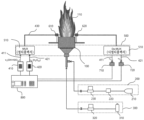
- FIG. 1 is a block diagram of an OH radical concentration measurement system in a reaction region using laser absorption spectroscopy according to an embodiment of the present invention.
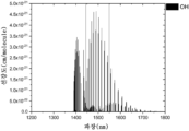
- FIG. 2 is a line intensity graph measured by a first laser according to an embodiment of the present invention.
- FIG. 3 is a graph illustrating an enlarged portion of a section of the graph of FIG. 3 .
- FIG. 5 is a flowchart of a method for measuring the concentration of OH radicals in a reaction region using laser absorption spectroscopy according to an embodiment of the present invention.
- Figure 6 is a flow chart showing in detail the step of measuring the OH radical concentration of Figure 5.
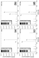
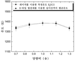
- FIG. 7 is a graph showing a method for measuring the concentration of OH radicals in the reaction zone using laser absorption spectroscopy according to an embodiment of the present invention and the temperature of the reaction zone measured with an R-type thermocouple.
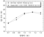
- FIG 8 and 9 are graphs showing the H 2 O concentration and the OH radical concentration measured by a method for measuring OH radical concentration in a reaction region using laser absorption spectroscopy and chemical reaction simulation according to an embodiment of the present invention.
- FIG. 1 is a block diagram of an OH radical concentration measurement system in a reaction region using laser absorption spectroscopy according to an embodiment of the present invention.
- the system 1 for measuring the concentration of OH radicals in a reaction region using laser absorption spectroscopy includes a reaction system 100, an air supply unit 200, a gas supply unit 300, a first laser irradiation unit 410, The second laser irradiation unit 420, the WDM system 500, the first collimating lens 610, the second collimating lens 620, the first photodetector 710, the second photodetector 720, and the control unit ( 800) may be included.
- the OH radical concentration measuring system 1 in the reaction zone using laser absorption spectroscopy is installed in the reaction system and can measure the reaction zone temperature, H 2 O concentration, and OH radical concentration generated in the reaction zone.
- the reaction region refers to a region in which various reactions occur as well as chemical reactions that generate heat and light, such as chemical reactions or flames.
- the reaction system 100 is a combustor, and the reaction region 110 may be a flame generated in the combustor.
- the air supply unit 200 may include an air storage unit 210, an air drying system 220, and a first mass flow controller 230.
- the air storage unit 210 may store air compressed by a compressor. Compressed air is supplied to the reaction system 100 through the air drying system 220 and the first mass flow controller 230, and may serve as an oxidizing agent in the reaction region 110.
- the air drying system 220 receives compressed air from the air storage unit 210, removes contaminants such as dust, oil, and moisture contained in the compressed air within a reference value based on the required degree to supply optimal compressed air. It is a system.
- the first mass flow controller 230 may measure and control the flow rate of compressed air. As the first mass flow controller 230 monitors the flow rate of compressed air, compressed air can be supplied to the reaction system 100 at a predetermined flow rate.
- the gas supply unit 300 may include a gas storage unit 310 and a second mass flow controller 320 .
- the gas storage unit 310 may store gas serving as a fuel in the reaction region 110 in the reaction system 100 .
- gas serving as a fuel in the reaction region 110 in the reaction system 100 .
- CH4 (methane) gas may be stored in the gas storage unit 310 .
- the gas storage unit 310 may supply the stored gas to the reaction system 100 through the second mass flow controller 320 .
- the second mass flow controller 320 may measure and control the flow rate of gas. As the second mass flow controller 320 monitors the gas flow rate, the gas can be supplied to the reaction system 100 at a preset flow rate.
- the first laser irradiator 410 may irradiate a first laser 411 having a first wavelength.
- the first wavelength may be in the range of 1450 to 1550 nm.
- the second laser irradiator 420 may irradiate a second laser 421 having a second wavelength.
- the second wavelength may be in the range of 1300 to 1400 nm.
- the first laser 411 and the second laser 421 having different wavelength ranges may be simultaneously irradiated through the first laser irradiation unit 410 and the second laser irradiation unit 420 .
- a WDM (Wavelength Division Multiplexing) system is for combining and separating a first laser 411 and a second laser 421 having different wavelength ranges, a multiplexer (510) and a de-multiplexer (520) can include
- the multiplexer 510 mixes the first laser 411 and the second laser generated by the first laser irradiation unit 410 and the second laser irradiation unit 420 into one laser, so that the mixed laser 430 is formed in the reaction area (110) to be investigated.
- the demultiplexer 520 may separate the mixed laser 430 transmitted through the reaction region 110 into a first laser 411 and a second laser 421 using a difference in refractive index of a wavelength.
- the first collimating lens 610 may perform collimating on the mixed laser 430 passing through the multiplexer 510 . Accordingly, the first collimating lens 610 may irradiate the mixed laser 430 to a predetermined measurement position within the reaction region 110 .
- the second collimating lens 620 may condense the mixed laser 430 irradiated from the first collimating lens 610 and transmitted through the reaction region 110, and transmit the mixed laser 430 to the aforementioned de-multiplexer 520. .
- the mixed laser 430 sequentially passing through the multiplexer 510, the first collimating lens 610, the reaction region 110, and the second collimating lens 620 is a de-multiplexer 520 ) can be separated into the first laser 411 and the second laser 421 again.
- the first photodetector 710 may focus the first laser 411 separated by the demultiplexer 520 .
- the first photodetector 710 may be a photodiode.
- the first photodetector 710 may detect a light absorption signal of the first laser 411 .
- the first photodetector 710 may detect an overlap signal (OH+H 2 O) obtained by overlapping the OH radical light absorption signal and the first H 2 O light absorption signal from the first laser 411 .
- the second photodetector 720 may focus the second laser 421 separated by the demultiplexer 520 .
- the second photodetector 720 may be a photodiode.
- the second photodetector 720 may detect a light absorption signal of the second laser 421 . Specifically, the second photodetector 720 may detect a single H 2 O light absorption signal absorbed by a single component of H 2 O from the second laser 421 .
- the controller 800 receives and receives the light absorption signal of the first laser 411 detected by the first photodetector 710 and the light absorption signal of the second laser 421 detected by the second photodetector 720. By analyzing the reaction zone temperature, H 2 O concentration and OH radical concentration can be measured.
- FIG. 2 is a line intensity graph measured by a first laser according to an embodiment of the present invention
- FIG. 3 is a graph showing an enlarged portion of a section of the graph of FIG. 3
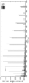
- FIG. 4 is a graph according to an embodiment of the present invention. It is a line intensity graph measured by the second laser.
- the first laser can effectively measure a line intensity range of 3.5 x 10 -21 or more within a wavelength range of 1400 to 1600 nm.
- the OH radical line intensity is high and the H 2 O line intensity is measured to be low, and the OH radical and H 2 O signals may overlap.
- the concentration of OH radicals in the reaction area corresponding to the concentration range of 0.01 to 0.5% can be measured.
- the second laser may measure flame temperature and H 2 O concentration in a linear intensity range of 1.0 x 10 -22 to 9.0 x 10 -22 within a wavelength range of 1300 to 1400 nm.
- the H 2 O concentration may be measurable in a flame environment corresponding to between 5% and 20%.
- FIG. 5 is a flowchart of a method for measuring the concentration of OH radicals in a reaction region using laser absorption spectroscopy according to an embodiment of the present invention.
- the method for measuring the concentration of OH radicals in the reaction region using laser absorption spectroscopy includes irradiating a first laser and a second laser (S100), mixing the first laser and the second laser (S200), and mixing the laser into the reaction region irradiating (S300), separating the mixed laser into a first laser and a second laser (S400), detecting the light absorption signal of the first laser and the second laser (S500), analyzing the light absorption signal and measuring the OH radical concentration (S600).
- the system 1 for measuring the concentration of OH radicals in a reaction region using laser absorption spectroscopy may irradiate a first laser and a second laser having different wavelengths (S100).
- the first laser irradiation unit 410 may irradiate a first laser 411 having a first wavelength
- the second laser irradiation unit 420 may irradiate a second laser 421 having a second wavelength.
- the first laser 411 and the second laser 421 of different wavelengths may be irradiated simultaneously.
- the system 1 for measuring the concentration of OH radicals in the reaction region using laser absorption spectroscopy may mix the first laser and the second laser (S200).
- the mixed laser 430 is irradiated by mixing the first laser 411 and the second laser 421 into one laser in a multiplexer 510 .
- the OH radical concentration measuring system 1 in the reaction region using laser absorption spectroscopy may irradiate the mixed laser to the reaction region generated in the reaction system (S300).
- the mixed laser 430 passing through the multiplexer 510 may be irradiated to a predetermined measurement position within the reaction region 110 generated in the reaction system 100 through the first collimating lens 610. there is.
- the system 1 for measuring the concentration of OH radicals in the reaction region using laser absorption spectroscopy may separate the mixed laser transmitted through the reaction region into a first laser and a second laser (S400).
- the mixed laser 430 transmitted through the reaction region 110 may be separated into a first laser 411 and a second laser 421 by a difference in refractive index of wavelength in a demultiplexer 520. there is.
- an overlapping signal (OH+H 2 O) of the OH radical light absorption signal and the first H 2 O light absorption signal may be detected from the first laser, and a single H 2 O light absorption signal may be detected from the second laser. (S500).
- the OH radical concentration measuring system 1 in the reaction region using laser absorption spectroscopy measures the OH radical concentration by separating only the first H 2 O optical absorption signal from the overlapping signal based on the single H 2 O optical absorption signal. It can (S600). Specifically, the light absorption signal of the first laser 411 detected by the first light detection unit 710 and the light absorption signal of the second laser 421 detected by the second light detection unit 720 in the control unit 800 By receiving and analyzing the reaction zone temperature, H 2 O concentration and OH radical concentration can be measured.
- the controller 800 controls the temperature of the reaction region and the concentration of H 2 O based on the Direct Absorption Spectroscopy (DAS) method among the Tunable Diode Laser Absorption Spectroscopy (TDLAS) method based on the optical method. And OH radical concentration can be measured simultaneously.
- DAS Direct Absorption Spectroscopy
- TDLAS Tunable Diode Laser Absorption Spectroscopy
- Equation 1 Equation 1 below, which represents a relationship between initial intensity and transmitted intensity.
- the absorption coefficient (k) of Equation 1 may be expressed as in Equation 2, and the product of the absorption coefficient (k) and the optical measurement distance (L) may be expressed as absorbance ( ⁇ ).
- the kind of chemical species to be measured in one embodiment of the present invention may be H 2 O and OH radicals.
- the DAS theory can be derived from Equation 2 above, and the step of measuring the OH radical concentration based on the DAS method will be described later.
- Figure 6 is a flow chart showing in detail the step of measuring the OH radical concentration of Figure 5.
- Measuring the OH radical concentration (S600) includes measuring the reaction zone temperature (S610), measuring the second H 2 O concentration (S620), and measuring the first H 2 O absorbance area (S630). ), deriving the OH radical absorbance by removing the first H 2 O absorbance area (S640), and measuring the OH radical concentration (S650).
- control unit 800 may measure the reaction region temperature based on a single H 2 O light absorption signal (S610). Specifically, two single H 2 O light absorption signals may exist, and the two single H 2 O light absorption signals are respectively referred to as a second H 2 O light absorption signal and a third H 2 O light absorption signal. The second H 2 O light absorption signal and the third H 2 O light absorption signal may exist within a wavelength range of the second laser 421 without overlapping each other.
- the temperature of the reaction region can be measured by substituting the data obtained from the second H 2 O light absorption signal and the third H 2 O light absorption signal into Equation 3 below.
- T flame is the temperature of the reaction region
- h is the Planck constant
- c is the speed of light
- k is the Boltzmann constant
- E" 1 _H20(#2) is the low-level state energy of the second H 2 O optical absorption signal
- E" 2 _H20(#2) is the low-level state energy of the 3rd H 2 O light absorption signal
- a 1_H2O(#2) is the absorbance area of the 2nd H 2 O light absorption signal
- a 2_H2O(#2) is the 3rd H 2
- S 1_H2O(#2) (T 0 ) is the second line intensity of the H 2 O light absorption signal at the reference temperature
- S 2_H2O(#2) (T 0 ) is the third at the reference temperature
- the linear intensity of the H 2 O light absorption signal, T 0 is the reference temperature.
- Equation 3 when there is only one single H 2 O light absorption signal, it is not applicable to Equation 3, that is, it is impossible to measure the temperature of the reaction region through the second laser 421.
- the temperature of the reaction region can be measured using other measuring sensors such as thermocouples and pyrometers.
- control unit 800 may measure the second H 2 O concentration included in the single H 2 O light absorption signal based on the second H 2 O line intensity of the single H 2 O light absorption signal analyzed from the reaction region temperature. It can (S620). Specifically, the second H 2 O linear intensity can be analyzed in the HITRAN Database by applying the measured reaction zone temperature value, and the second H 2 O concentration ( ⁇ H 2 O (#2 ) ) can be calculated.
- ⁇ H O (#2) is the second H 2 O absorbance of a single H 2 O light absorption signal
- P is the pressure in the measurement environment
- ⁇ H O (#2) is the second H of a single H 2 O light absorption signal 2 O concentration
- S i,j (T) is the second H 2 O line intensity of a single H 2 O optical absorption signal
- L is the optical measurement distance
- a H 2 O (#2) is the first H 2 O optical absorption signal 2 H 2 O is the absorbance area.
- Equation 4 is a function for obtaining the absorbance area
- Equation 5 which is a function for obtaining the concentration of H 2 O, can be derived from Equation 4 above.
- the controller 800 may measure the first H 2 O absorbance area of the first H 2 O light absorption signal based on the second H 2 O concentration (S630). Specifically, as shown in Equation 6 below, the first H 2 O concentration ( ⁇ H 2 O (#1) ) included in the overlapping signal (OH+H 2 O) and the second H 2 O included in the single H 2 O light absorption signal The H 2 O concentration ( ⁇ H 2 O (#2) ) may be the same. This can be theoretically established because the first laser 411 and the second laser 421 are transmitted through the same time and space. Accordingly, the first H 2 O absorbance area A H 2 O (# 1) may be measured by substituting the previously measured second H 2 O concentration ⁇ H 2 O( # 2) into Equation 7 below.
- ⁇ H2O(#2) is the second H2O concentration of the single H2O light absorption signal
- ⁇ H2O(#1) is the first H2O concentration of the overlapping signal.
- a H2O(#1) is the first H2O absorbance area of the first H2O light absorption signal
- ⁇ H2O(#1) is the first H2O absorbance of the first H2O light absorption signal
- P is the pressure in the measurement environment
- ⁇ H2O(#2) is the second H 2 O concentration of the single H 2 O light absorption signal
- S i,j (T) is the second H 2 O of the single H 2 O light absorption signal Line intensity
- L is the optical measurement distance.
- the controller 800 may derive the OH radical absorbance by removing the first H 2 O absorbance area from the absorbance area of the overlapped signal (OH+H 2 O) (S640).
- the absorbance area of the overlapping signal (OH+H 2 O) is a state previously measured from the light absorption signal of the first laser 411, and the first H 2 O absorbance area is obtained by Equation 7 above in step S630. It is a pre-measured state.
- Equation 8 a single OH radical absorbance ( ⁇ OH ) can be derived.
- a OH is the OH radical absorbance area of the OH radical light absorption signal
- a OH + H O (#1) is the absorbance area of the overlapping signal (OH + H O)
- a H O (# 1) is the first H 2 O light
- ⁇ OH is the OH radical absorbance of the OH radical light absorption signal
- ⁇ OH + H2O (#1) is the absorbance of the superimposed signal (OH + H2O)
- ⁇ H2O (#1) is the first It is the first H2O absorbance of the H 2 O optical absorption signal.
- control unit 800 may measure the OH radical concentration based on the OH radical line intensity analyzed from the temperature of the reaction region (S650). Specifically, the OH radical linear intensity can be analyzed in the HITRAN Database by applying the measured reaction zone temperature value, and the OH radical concentration ( ⁇ OH ) can be calculated by applying this to Equations 9 and 10 below.
- ⁇ OH is the OH radical absorbance of the OH radical light absorption signal
- P is the pressure in the measurement environment
- ⁇ OH is the OH radical concentration of the OH radical light absorption signal
- S i,j (T) is the OH radical light absorption signal OH radical linear intensity
- L is the optical measurement distance
- a OH is the OH radical absorbance area of the OH radical optical absorption signal.
- Equation 9 is a function for obtaining the absorbance area
- Equation 10 which is a function for obtaining the concentration of OH radicals, can be derived from Equation 9.
- the method for measuring the concentration of OH radicals in the reaction region using laser absorption spectroscopy is based on the Direct Absorption Spectroscopy (DAS) method, which is superimposed on the OH radical absorption signal in the near-infrared wavelength region.
- DAS Direct Absorption Spectroscopy
- FIG. 7 is a graph showing a method for measuring the concentration of OH radicals in the reaction zone using laser absorption spectroscopy according to an embodiment of the present invention and the temperature of the reaction zone measured with an R-type thermocouple
- FIGS. 8 and 9 are examples of the present invention. It is a graph showing the H 2 O concentration and the OH radical concentration measured by the OH radical concentration measurement method and chemical reaction simulation in the reaction region using laser absorption spectroscopy according to the embodiment.
- the temperature measured based on the DAS method of the present invention shows a similar tendency to the temperature measured with the R-Type thermocouple, and the H 2 O concentration and OH radical concentration are chemical reaction simulation Chemkin (GRI 3.0) and When compared, a similar tendency was obtained according to the equivalence ratio.
Landscapes
- Physics & Mathematics (AREA)
- Spectroscopy & Molecular Physics (AREA)
- General Physics & Mathematics (AREA)
- Engineering & Computer Science (AREA)
- Health & Medical Sciences (AREA)
- Life Sciences & Earth Sciences (AREA)
- Chemical & Material Sciences (AREA)
- Analytical Chemistry (AREA)
- Biochemistry (AREA)
- General Health & Medical Sciences (AREA)
- Immunology (AREA)
- Pathology (AREA)
- Theoretical Computer Science (AREA)
- Data Mining & Analysis (AREA)
- Mathematical Physics (AREA)
- Mathematical Analysis (AREA)
- Computational Mathematics (AREA)
- Algebra (AREA)
- Optics & Photonics (AREA)
- Mathematical Optimization (AREA)
- Pure & Applied Mathematics (AREA)
- Databases & Information Systems (AREA)
- Software Systems (AREA)
- General Engineering & Computer Science (AREA)
- Nuclear Medicine, Radiotherapy & Molecular Imaging (AREA)
- Toxicology (AREA)
- Investigating Or Analysing Materials By Optical Means (AREA)
Abstract
본 발명의 일 실시예에 따른 레이저 흡수분광법을 이용한 반응영역 내 OH라디칼 농도 측정 시스템은, 서로 다른 파장의 제1 레이저 및 제2 레이저를 조사하는 단계, 상기 제1 레이저 및 상기 제2 레이저를 혼합하는 단계, 반응시스템에서 발생하는 반응영역으로 혼합 레이저를 조사하는 단계, 상기 반응영역을 투과한 상기 혼합 레이저를 상기 제1 레이저 및 상기 제2 레이저로 분리하는 단계, 상기 제1 레이저에서 OH라디칼 광흡수신호 및 제1 H2O 광흡수신호의 중첩신호(OH+H2O)를 검출하고, 제2 레이저에서 H2O 단일성분에 의해 흡수된 단일 H2O 광흡수신호를 검출하는 단계 및 상기 단일 H2O 광흡수신호를 기초로, 상기 중첩신호에서 상기 제1 H2O 광흡수신호만을 분리함으로써 OH라디칼 농도를 측정하는 단계를 포함할 수 있다.
Description
레이저 흡수분광법을 이용한 반응영역 내 OH라디칼 농도 측정 방법에 관한 것이다.
전세계적으로 지구온난화 억제를 위해 탄소 중립 정책이 시행되고 있다. 현재 탄화수소 연료는 대부분의 연소 시스템의 에너지 생산에 기여하지만 탄소 중립 정책으로 탄화수소기반 연료 사용이 점차 줄어들고 있다. 이를 대체하기 위해서 탄화수소 연료 개질로부터 생산된 수소계열의 (수소, 암모니아 및 합성 연료) 연료 사용이 2050년까지 크게 증가할 것으로 예상된다. 하지만 수소, 암모니아 연료 기반 연소시스템에서도 대기오염물질의 전구물질(질소산화물)이 생성(온실가스와 trade-off)되기 때문에 새로운 고효율 저공해 수소, 암모니아 연료 기반 연소 시스템 개발이 요구되고 있다.
OH 라디칼은 연소 시스템의 효율과 대기오염물질 생성에 밀접한 화학종이다. 화염 내 OH 라디칼은 연쇄분지반응(Branching reaction)이나 전파 반응(Propagation reaction)에 주요한 운반자로 연소 효율에 밀접한 영향을 끼치고 또한 화염의 산화제를 공기로 사용할 때 고온 등 여러가지 조건에서 NOX로 변하기 때문에 미세먼지 전구물질 생성에도 연관성을 가진다. 하지만 큰 연소시스템에서 빠른 유동과 열악한 환경으로 인하여 OH 라디칼 농도 측정은 어려운 실정이다. 특히 화염 내 OH 라디칼은 약 2ns 안에 생성과 소멸이 일어나는 특성으로 정량적 농도 측정이 어렵다. 이러한 이유로 연소 환경에서 화염을 직접적으로 진단하기 위한 개발이 활발히 진행되고 있다. 그 중 비접촉식 방식으로 각광을 받고 있는 광학 측정 기술이 화염 거동을 이해하기 위한 방법으로 제안되고 있다.
화염 내 OH 라디칼을 측정하는 일반적인 광학 측정 방법은 레이저 유도 형광법(Laser Induced Fluorescence, LIF), 화학발광법 (Chemiluminescence, CL), 그리고 파장 가변형 다이오드 레이저 흡수 분광법 등으로 분류될 수 있다. 레이저 유도 형광법은 주로 정성적 이미지 분석에 사용되며 가혹한 환경에서 측정하기 어려운 대형 레이저 시스템의 단점을 가지고 있다. 화학발광법은 OH 라디칼 분포의 정성적 특성을 확인하는데 자주 사용되며 정량적 농도 분석에 오류가 존재한다. 마지막으로 본 발명에 적용된 좁은 선폭(narrow line width)의 레이저 광원을 사용하는 파장 가변형 다이오드 레이저 흡수 분광법은 화학종에 따라서 특정한 파장을 흡수하는 원리를 이용하기 때문에 정량적 농도 측정에 널리 적용되고 있는 방식이다. 또한 화염 및 가스 유동에서 높은 시간 분해능 및 in-situ 측정을 기반으로 가혹한 환경에서도 측정할 수 있는 장점을 가진다.
일반적으로 OH 라디칼을 측정하기 위해서 근적외선 파장의 레이저가 사용된다. 하지만 근적외선 영역에서 OH 라디칼 파장은 H2O 파장이 중첩되는 문제점을 가지고 있다. 이를 해결하기 위해 화염 내 OH 라디칼 농도를 측정하는 기존 방법은 흡수 분광학적 이론(HITRAN/HITEMP)을 기반으로 H2O 흡수 신호를 모사(Simulation)하여 OH 라디칼 흡수 신호에 중첩된 H2O 흡수 신호를 제거하는 방식으로 이루어졌다. 그러나 이러한 방법은 복잡한 모사 방식과 반복 계산(iterative calculations)이 필요하게 되는 문제점이 있었다.
본 발명의 일 실시예는, 광학 방식 기반의 파장 가변형 다이오드 레이저 흡수 분광법(Tunable Diode Laser Absorption Spectroscopy, TDLAS)방법 중 직접 흡수 분광법(Direct Absorption Spectroscopy, DAS)을 이용하여 반응영역 내 OH 라디칼 농도 측정 방법을 제안하고 복잡한 모사 방식과 반복 계산 없이 반응영역 온도, H2O 농도 및 OH라디칼 농도를 동시에 측정할 수 있는 레이저 흡수분광법을 이용한 반응영역 내 OH라디칼 농도 측정 방법을 제공하고자 한다.
본 발명의 일 실시예에 따른 레이저 흡수분광법을 이용한 반응영역 내 OH라디칼 농도 측정 시스템은, 서로 다른 파장의 제1 레이저 및 제2 레이저를 조사하는 단계, 상기 제1 레이저 및 상기 제2 레이저를 혼합하는 단계, 반응시스템에서 발생하는 반응영역으로 혼합 레이저를 조사하는 단계, 상기 반응영역을 투과한 상기 혼합 레이저를 상기 제1 레이저 및 상기 제2 레이저로 분리하는 단계, 상기 제1 레이저에서 OH라디칼 광흡수신호 및 제1 H2O 광흡수신호의 중첩신호(OH+H2O)를 검출하고, 제2 레이저에서 H2O 단일성분에 의해 흡수된 단일 H2O 광흡수신호를 검출하는 단계 및 상기 단일 H2O 광흡수신호를 기초로, 상기 중첩신호에서 상기 제1 H2O 광흡수신호만을 분리함으로써 OH라디칼 농도를 측정하는 단계를 포함할 수 있다.
상기 측정하는 단계는, 상기 단일 H2O 광흡수신호를 기초로 반응영역 온도를 측정하는 단계, 상기 반응영역 온도로부터 분석된 상기 단일 H2O 광흡수신호의 제2 H2O 선강도를 기초로, 상기 단일 H2O 광흡수신호에 포함된 제2 H2O 농도를 측정하는 단계, 상기 제2 H2O 농도를 기초로 상기 제1 H2O 광흡수신호의 제1 H2O 흡광도 면적을 측정하는 단계, 상기 중첩신호(OH+H2O)의 흡광도 면적에서 상기 제1 H2O 흡광도 면적을 제거하여 OH라디칼 흡광도를 도출하는 단계 및 상기 반응영역 온도로부터 분석된 OH라디칼 광흡수신호의 선강도를 기초로 상기 OH라디칼 농도를 측정하는 단계를 포함할 수 있다.
상기 반응영역 온도를 측정하는 단계는, 상기 단일 H2O 광흡수신호가 2개로 존재하고, 2개의 상기 단일 H2O 광흡수신호 각각은 제2 H2O 광흡수신호 및 제3 H2O 광흡수신호이며, 하기 수학식 3에 따라 상기 반응영역 온도를 측정할 수 있다.
[수학식 3]

(여기서, Tflame는 반응영역 온도, h는 플랑크 상수, c는 빛의 속도, k는 볼츠만 상수, E"1
_H20(#2)는 제2 H2O 광흡수신호의 저준위 상태에너지, E"2
_H20(#2)는 제3 H2O 광흡수신호의 저준위 상태에너지, A1_H2O(#2)는 제2 H2O 광흡수신호의 흡광도 면적, A2_H2O(#2)는 제3 H2O 광흡수신호의 흡광도 면적, S1_H2O(#2)(T0)는 기준온도에서 제2 H2O 광흡수신호의 선강도, S2_H2O(#2)(T0)는 기준온도에서 제3 H2O 광흡수신호의 선강도, T0는 기준온도이다.)
상기 단일 H2O 광흡수신호에 포함된 제2 H2O 농도를 측정하는 단계는, 하기 수학식 4로부터 도출된 하기 수학식 5에 따라 상기 제2 H2O 농도를 측정할 수 있다.
[수학식 4]

[수학식 5]

(여기서, αH2O(#2)는 단일 H2O 광흡수신호의 제2 H2O 흡광도, P는 측정환경 내 압력, χH2O(#2)는 단일 H2O 광흡수신호의 제2 H2O 농도, Si,j(T)는 단일 H2O 광흡수신호의 제2 H2O 선강도, L는 광측정거리, AH2O(#2)는 단일 H2O 광흡수신호의 제2 H2O 흡광도 면적이다.)
상기 중첩신호(OH+H2O)에 포함된 제1 H2O 농도와, 상기 단일 H2O 광흡수신호에 포함된 제2 H2O 농도는 동일하며, 이는 하기 수학식 6으로 표현될 수 있다.
[수학식 6]

(여기서, χH2O(#2)는 단일 H2O 광흡수신호의 제2 H2O 농도, χH2O(#1)는 중첩신호의 제1 H2O 농도이다.)
상기 제1 H2O 광흡수신호의 제1 H2O 흡광도 면적을 측정하는 단계는, 상기 수학식 4 및 상기 수학식 6으로부터 도출된 하기 수학식 7에 따라 상기 제1 H2O 흡광도 면적을 측정할 수 있다.
[수학식 7]

(여기서, AH2O(#1)는 제1 H2O 광흡수신호의 제1 H2O 흡광도 면적, αH2O(#1)는 제1 H2O 광흡수신호의 제1 H2O 흡광도, P는 측정환경 내 압력, χH2O(#2)는 단일 H2O 광흡수신호의 제2 H2O 농도, Si,j(T)는 단일 H2O 광흡수신호의 제2 H2O 선강도, L은 광측정거리이다.)
상기 OH라디칼 흡광도를 도출하는 단계는, 하기 수학식 8에 따라 상기 OH라디칼 흡광도를 도출할 수 있다.
[수학식 8]

(여기서, AOH는 OH라디칼 광흡수신호의 OH라디칼 흡광도 면적, AOH
+H2O(#1)는 중첩신호(OH+H2O)의 흡광도 면적, AH2O(#1)는 제1 H2O 광흡수신호의 제1 H2O 흡광도 면적, αOH는 OH라디칼 광흡수신호의 OH라디칼 흡광도, αOH
+H2O(#1)는 중첩신호(OH+H2O)의 흡광도, αH2O(#1)는 제1 H2O 광흡수신호의 제1 H2O 흡광도이다.)
상기 반응영역 온도로부터 분석된 OH라디칼 선강도를 기초로 상기 OH라디칼 농도를 측정하는 단계는, 하기 수학식 9로부터 도출된 하기 수학식 10에 따라 상기 OH라디칼 농도를 측정할 수 있다.
[수학식 9]

[수학식 10]

(여기서, αOH는 OH라디칼 광흡수신호의 OH라디칼 흡광도, P는 측정환경 내 압력, χOH는 OH라디칼 광흡수신호의 OH라디칼 농도, Si,j(T)는 OH라디칼 광흡수신호의 OH라디칼 선강도, L는 광측정거리, AOH는 OH라디칼 광흡수신호의 OH라디칼 흡광도 면적이다.)
제1 레이저는 1450 ~ 1550 nm의 파장 범위를 가지고, 제2 레이저는 1300 nm ~ 1400 nm의 파장 범위를 가질 수 있다.
본 발명의 일 실시예에 따른 레이저 흡수분광법을 이용한 반응영역 내 OH라디칼 농도 측정 방법은, 향상된 DAS 방법을 기반으로 근적외선 파장 영역에서 OH 라디칼 흡수 신호에 중첩되는 H2O 흡수신호를 제거하는 방법을 적용하고, 복잡한 모사 방식과 반복 계산 없이 반응영역 온도, H2O 농도 및 OH라디칼 농도를 동시에 측정할 수 있는 효과가 있다.
도 1은 본 발명의 일 실시예에 따른 레이저 흡수분광법을 이용한 반응영역 내 OH라디칼 농도 측정 시스템의 구성도이다.
도 2는 본 발명의 일 실시예에 따른 제1 레이저로 측정한 선강도 그래프이다.
도 3은 도 3 그래프의 일부 구간을 확대하여 도시한 그래프이다.
도 4는 본 발명의 일 실시예에 따른 제2 레이저로 측정한 선강도 그래프이다.
도 5는 본 발명의 일 실시예에 따른 레이저 흡수분광법을 이용한 반응영역 내 OH라디칼 농도 측정 방법의 순서도이다.
도 6은 도 5의 OH라디칼 농도를 측정하는 단계를 상세히 나타낸 순서도이다.
도 7는 본 발명의 일 실시예에 따른 레이저 흡수분광법을 이용한 반응영역 내 OH라디칼 농도 측정 방법 및 R-type 열전대로 측정된 반응영역 온도를 나타낸 그래프이다.
도 8 및 도 9는 본 발명의 일 실시예에 따른 레이저 흡수분광법을 이용한 반응영역 내 OH라디칼 농도 측정 방법 및 화학반응시뮬레이션으로 측정된 H2O 농도 및 OH라디칼 농도를 각각 나타낸 그래프이다.
이하, 첨부한 도면을 참고로 하여 본 발명의 실시예에 대하여 본 발명이 속하는 기술분야에서 통상의 지식을 가진 자가 용이하게 실시할 수 있도록 상세히 설명한다. 본 발명은 여러 가지 상이한 형태로 구현될 수 있으며 여기에서 설명하는 실시예에 한정되지 않는다. 도면에서 본 발명을 명확하게 설명하기 위해서 설명과 관계없는 부분은 생략하였으며, 명세서 전체를 통하여 동일 또는 유사한 구성요소에 대해서는 동일한 참조부호를 붙였다.
본 명세서에서, "포함하다" 또는 "가지다" 등의 용어는 명세서상에 기재된 특징, 숫자, 단계, 동작, 구성 요소, 부품 또는 이들을 조합한 것이 존재함을 지정하려는 것이지, 하나 또는 그 이상의 다른 특징들이나 숫자, 단계, 동작, 구성 요소, 부분품 또는 이들을 조합한 것들의 존재 또는 부가 가능성을 미리 배제하지 않는 것으로 이해되어야 한다.
도 1은 본 발명의 일 실시예에 따른 레이저 흡수분광법을 이용한 반응영역 내 OH라디칼 농도 측정 시스템의 구성도이다.
먼저, 도 1을 참고로 본 발명의 일 실시예에 따른 레이저 흡수분광법을 이용한 반응영역 내 OH라디칼 농도 측정 시스템(1)에 대해 설명한다.
도 1을 참고하면, 레이저 흡수분광법을 이용한 반응영역 내 OH라디칼 농도 측정 시스템(1)은, 반응시스템(100), 공기공급부(200), 가스공급부(300), 제1 레이저조사부(410), 제2 레이저조사부(420), WDM 시스템(500), 제1 콜리메이트 렌즈(610), 제2 콜리메이트 렌즈(620), 제1 광검출부(710), 제2 광검출부(720) 및 제어부(800)를 포함할 수 있다.
레이저 흡수분광법을 이용한 반응영역 내 OH라디칼 농도 측정 시스템(1)은 반응시스템에 설치되어 반응영역에서 발생하는 반응영역 온도, H2O 농도, OH라디칼 농도를 측정할 수 있다. 여기서, 반응영역은 화학적 반응 또는 화염과 같이 열과 빛을 발생하는 화학반응뿐만 아니라 다양한 반응이 발생하는 영역을 의미한다. 도면들의 설명에서, 반응시스템(100)은 연소기이고, 반응영역(110)은 연소기에서 발생하는 화염일 수 있다.
공기공급부(200)는 공기저장부(210), 공기건조시스템(220), 제1 질량유량제어기(230)를 포함할 수 있다.
공기저장부(210)는 압축기에 의해 압축된 공기가 저장될 수 있다. 압축공기는 공기건조시스템(220) 및 제1 질량유량제어기(230)를 통해 반응시스템(100)로 공급되어, 반응영역(110)에서의 산화제로서 역할을 할 수 있다.
공기건조시스템(220)은 공기저장부(210)로부터 압축공기를 공급받아, 압축공기 중에 포함되는 먼지, 유분, 수분 등의 오염물질을 요구 정도에 기초한 기준값 내로 제거하여 최적의 압축공기를 공급하는 시스템이다.
제1 질량유량제어기(230)는 압축공기의 유량을 측정 및 제어할 수 있다. 제1 질량유량제어기(230)는 압축공기의 유량을 모니터링함에 따라, 압축공기를 기설정된 유량으로 반응시스템(100)에 공급되도록 할 수 있다.
가스공급부(300)는 가스저장부(310) 및 제2 질량유량제어기(320)를 포함할 수 있다.
가스저장부(310)는 반응시스템(100)에서 반응영역(110)에서의 연료로서 역할을 하는 가스가 저장될 수 있다. 예를 들어, 가스저장부(310)에는 CH4(메탄)가스가 저장될 수 있다. 가스저장부(310)는 저장된 가스를 제2 질량유량제어기(320)를 통해 반응시스템(100)로 공급할 수 있다.
제2 질량유량제어기(320)는 가스의 유량을 측정 및 제어할 수 있다. 제2 질량유량제어기(320)는 가스의 유량을 모니터링함에 따라, 가스를 기설정된 유량으로 반응시스템(100)에 공급되도록 할 수 있다.
제1 레이저조사부(410)는 제1 파장을 갖는 제1 레이저(411)를 조사할 수 있다. 예를 들어, 제1 파장은 1450 ~ 1550nm 범위일 수 있다.
제2 레이저조사부(420)는 제2 파장을 갖는 제2 레이저(421)를 조사할 수 있다. 예를 들어, 제2 파장은 1300 ~ 1400nm 범위일 수 있다.
즉, 제1 레이저조사부(410) 및 제2 레이저조사부(420)를 통해 서로 다른 파장 범위를 갖는 제1 레이저(411) 및 제2 레이저(421)를 동시에 조사할 수 있다.
WDM(Wavelength Division Multiplexing)시스템은 서로 다른 파장 범위를 갖는 제1 레이저(411) 및 제2 레이저(421)를 결합 및 분리하기 위한 것으로, 멀티플렉서(Multiplexer, 510) 및 디멀티플렉서(De-Multiplexer, 520)를 포함할 수 있다.
멀티플렉서(Multiplexer, 510)는 제1 레이저조사부(410) 및 제2 레이저조사부(420)에서 발생된 제1 레이저(411) 및 제2 레이저를 하나의 레이저로 혼합함으로써 혼합 레이저(430)가 반응영역(110)에 조사될 수 있도록 한다.
디멀티플렉서(De-Multiplexer, 520)는 반응영역(110)을 투과한 혼합 레이저(430)를 파장의 굴절률 차이를 이용하여 제1 레이저(411) 및 제2 레이저(421)로 다시 분리할 수 있다.
한편, 제1 콜리메이트 렌즈(610)는 멀티플렉서(Multiplexer, 510)를 통과한 혼합 레이저(430)에 대한 콜리메이팅을 수행할 수 있다. 이에 따라, 제1 콜리메이트 렌즈(610)는 혼합 레이저(430)를 반응영역(110) 내 소정의 측정 위치로 조사할 수 있다.
제2 콜리메이트 렌즈(620)는 제1 콜리메이트 렌즈(610)에서 조사되어 반응영역(110)을 투과한 혼합 레이저(430)를 집광하여 전술한 디멀티플렉서(De-Multiplexer, 520)로 전달할 수 있다.
즉, 멀티플렉서(Multiplexer, 510), 제1 콜리메이트 렌즈(610), 반응영역(110) 및 제2 콜리메이트 렌즈(620)를 순차적으로 통과한 혼합 레이저(430)는 디멀티플렉서(De-Multiplexer, 520)에서 다시 제1 레이저(411) 및 제2 레이저(421)로 분리될 수 있다.
제1 광검출부(710)는 디멀티플렉서(De-Multiplexer, 520)에서 분리된 제1 레이저(411)를 집광할 수 있다. 예를 들어, 제1 광검출부(710)는 포토 다이오드 일 수 있다.
또한, 제1 광검출부(710)는 제1 레이저(411)의 광흡수신호를 검출할 수 있다. 구체적으로, 제1 광검출부(710)는 제1 레이저(411)로부터 OH라디칼 광흡수신호 및 제1 H2O 광흡수신호가 중첩된 중첩신호(OH+H2O)를 검출할 수 있다.
제2 광검출부(720)는 디멀티플렉서(De-Multiplexer, 520)에서 분리된 제2 레이저(421)를 집광할 수 있다. 예를 들어, 제2 광검출부(720)는 포토 다이오드 일 수 있다.
또한, 제2 광검출부(720)는 제2 레이저(421)의 광흡수신호를 검출할 수 있다. 구체적으로, 제2 광검출부(720)는 제2 레이저(421)로부터 H2O 단일성분에 의해 흡수된 단일 H2O 광흡수신호를 검출할 수 있다.
제어부(800)는 제1 광검출부(710)에서 검출된 제1 레이저(411)의 광흡수신호와, 제2 광검출부(720)에서 검출된 제2 레이저(421)의 광흡수신호를 수신 및 분석하여 반응영역 온도, H2O 농도 및 OH라디칼 농도를 측정할 수 있다.
도 2는 본 발명의 일 실시예에 따른 제1 레이저로 측정한 선강도 그래프이고, 도 3은 도 3 그래프의 일부 구간을 확대하여 도시한 그래프이며, 도 4는 본 발명의 일 실시예에 따른 제2 레이저로 측정한 선강도 그래프이다.
도 2 내지 도 4는 1000K ~ 2000K (726.85C-1726.85C)사이 화염 온도 범위의 측정환경에서 측정되었다.
도 2 및 도 3을 참고하면, 제1 레이저는 1400 ~ 1600 nm 파장 범위내에서 3.5 x 10⁻²¹ 이상 강한 선강도 범위를 효과적으로 측정할 수 있다. 바람직하게는, 제1 레이저가 1450 ~ 1550nm 파장 범위일 경우 OH라디칼 선강도는 높고 H2O 선강도가 낮게 측정되며 OH라디칼 및 H2O 신호가 중첩될 수 있다. 이때, 0.01 ~ 0.5% 농도 범위에 해당되는 반응영역 내 OH라디칼 농도를 측정할 수 있다.
도 4를 참고하면, 제2 레이저는 1300 ~ 1400 nm 파장 범위내에서 1.0 x 10⁻²² ~ 9.0 x 10⁻²² 범위의 선강도 범위에서 화염온도 및 H2O 농도를 측정할 수 있다. 이때, H2O 농도 5 % - 20% 사이에 해당되는 화염 환경에서 측정가능 할 수 있다.
도 5는 본 발명의 일 실시예에 따른 레이저 흡수분광법을 이용한 반응영역 내 OH라디칼 농도 측정 방법의 순서도이다.
도 5를 참고로 레이저 흡수분광법을 이용한 반응영역 내 OH라디칼 농도 측정 방법에 대해서 설명한다.
레이저 흡수분광법을 이용한 반응영역 내 OH라디칼 농도 측정 방법은, 제1 레이저 및 제2 레이저를 조사하는 단계(S100), 제1 레이저 및 제2 레이저를 혼합하는 단계(S200), 반응영역으로 혼합 레이저를 조사하는 단계(S300), 혼합 레이저를 제1 레이저 및 제2 레이저로 분리하는 단계(S400), 제1 레이저 및 제2 레이저의 광흡수신호를 검출하는 단계(S500), 광흡수신호를 분석하여 OH라디칼 농도를 측정하는 단계(S600)를 포함할 수 있다.
먼저, 레이저 흡수분광법을 이용한 반응영역 내 OH라디칼 농도 측정 시스템(1)은 서로 다른 파장의 제1 레이저 및 제2 레이저를 조사할 수 있다(S100). 구체적으로, 제1 레이저조사부(410)에서 제1 파장을 갖는 제1 레이저(411)를 조사하고, 제2 레이저조사부(420)에서 제2 파장을 갖는 제2 레이저(421)를 조사할 수 있다. 이때, 서로 다른 파장의 제1 레이저(411) 및 제2 레이저(421)는 동시에 조사될 수 있다.
이후, 레이저 흡수분광법을 이용한 반응영역 내 OH라디칼 농도 측정 시스템(1)은 제1 레이저 및 제2 레이저를 혼합할 수 있다(S200). 구체적으로, 멀티플렉서(Multiplexer, 510)에서 제1 레이저(411) 및 제2 레이저(421)를 하나의 레이저로 혼합함으로써 혼합 레이저(430)가 조사될 수 있도록 한다.
이후, 레이저 흡수분광법을 이용한 반응영역 내 OH라디칼 농도 측정 시스템(1)은 반응시스템에서 발생하는 반응영역으로 혼합 레이저를 조사할 수 있다(S300). 구체적으로, 멀티플렉서(Multiplexer, 510)를 통과한 혼합 레이저(430)는 제1 콜리메이트 렌즈(610)를 통해 반응시스템(100)에서 발생하는 반응영역(110) 내 소정의 측정 위치로 조사될 수 있다.
이후, 레이저 흡수분광법을 이용한 반응영역 내 OH라디칼 농도 측정 시스템(1)은 반응영역을 투과한 혼합 레이저를 제1 레이저 및 제2 레이저로 분리할 수 있다(S400). 구체적으로, 반응영역(110)을 투과한 혼합 레이저(430)는 디멀티플렉서(De-Multiplexer, 520)에서 파장의 굴절률 차이에 의해 제1 레이저(411) 및 제2 레이저(421)로 다시 분리될 수 있다.
이후, 제1 레이저에서 OH라디칼 광흡수신호 및 제1 H2O 광흡수신호의 중첩신호(OH+H2O)를 검출하고, 제2 레이저로부터 단일 H2O 광흡수신호를 검출할 수 있다(S500).
이후, 레이저 흡수분광법을 이용한 반응영역 내 OH라디칼 농도 측정 시스템(1)은 단일 H2O 광흡수신호를 기초로, 중첩신호에서 제1 H2O 광흡수신호만을 분리함으로써 OH라디칼 농도를 측정할 수 있다(S600). 구체적으로, 제어부(800)에서 제1 광검출부(710)에서 검출된 제1 레이저(411)의 광흡수신호와, 제2 광검출부(720)에서 검출된 제2 레이저(421)의 광흡수신호를 수신 및 분석하여 반응영역 온도, H2O 농도 및 OH라디칼 농도를 측정할 수 있다.
이때, 제어부(800)는 광학 방식 기반의 파장 가변형 다이오드 레이저 흡수 분광법(Tunable Diode Laser Absorption Spectroscopy, TDLAS)방법 중 직접 흡수 분광법(Direct Absorption Spectroscopy, DAS) 방법을 기반으로 반응영역 온도, H2O 농도 및 OH라디칼 농도를 동시에 측정할 수 있다.
TDLAS이론은 Beer-Lambert 법칙에 근거한다. 구체적으로, 특정한 파장(v)을 가지는 레이저가 반응영역으로 투과될 때, 투과율은 초기 강도와 투과된 강도의 관계를 나타내는 하기의 수학식 1로 표현될 수 있다.
[수학식 1]

(여기서, τ는 투과율, I는 입사광의 세기, I0는 투사광의 세기, k는 흡수계수, L은 광측정거리이다.)
이때, 수학식 1의 흡수계수(k)는 수학식 2와 같이 표현될 수 있으며, 흡수 계수(k)와 광측정거리(L)의 곱은 흡광도(α)로 표현될 수 있다.
[수학식 2]

(여기서, k는 흡수계수, Si,j(T)는 측정되는 화학종의 선강도, P는 측정환경 내 압력, χi는 화학종(i)의 농도, φ는 흡수신호의 선형상이다.)
이때, 본 발명의 일 실시예에서 측정하고자 하는 화학종의 종류는 H2O 및 OH라디칼일 수 있다.
DAS 이론은 상기 수학식 2로부터 유도될 수 있으며, DAS 방법을 기반으로한 OH라디칼 농도를 측정하는 단계에 대해서 후술하도록 한다.
도 6은 도 5의 OH라디칼 농도를 측정하는 단계를 상세히 나타낸 순서도이다.
도 6을 참고하여 DAS 방법을 기반으로 반응영역 온도, H2O 농도 및 OH라디칼 농도를 측정하는 방법에 대해서 설명한다.
OH라디칼 농도를 측정하는 단계(S600)는, 반응영역 온도를 측정하는 단계(S610), 제2 H2O 농도를 측정하는 단계(S620), 제1 H2O 흡광도 면적을 측정하는 단계(S630), 제1 H2O 흡광도 면적을 제거하여 OH라디칼 흡광도를 도출하는 단계(S640), OH라디칼 농도를 측정하는 단계(S650)를 포함할 수 있다.
먼저, 제어부(800)는 단일 H2O 광흡수신호를 기초로 반응영역 온도를 측정할 수 있다(S610). 구체적으로, 단일 H2O 광흡수신호는 2개로 존재할 수 있으며, 2개의 단일 H2O 광흡수신호는 각각 제2 H2O 광흡수신호 및 제3 H2O 광흡수신호로 명명한다. 제2 H2O 광흡수신호 및 제3 H2O 광흡수신호는 제2 레이저(421)의 파장 범위 내에서 서로 겹치지 않게 존재할 수 있다.
이때, 제2 H2O 광흡수신호 및 제3 H2O 광흡수신호로부터 얻은 데이터를 하기 수학식 3에 대입함으로써 반응영역 온도를 측정할 수 있다.
[수학식 3]

(여기서, Tflame는 반응영역 온도, h는 플랑크 상수, c는 빛의 속도, k는 볼츠만 상수, E"1
_H20(#2)는 제2 H2O 광흡수신호의 저준위 상태에너지, E"2
_H20(#2)는 제3 H2O 광흡수신호의 저준위 상태에너지, A1_H2O(#2)는 제2 H2O 광흡수신호의 흡광도 면적, A2_H2O(#2)는 제3 H2O 광흡수신호의 흡광도 면적, S1_H2O(#2)(T0)는 기준온도에서 제2 H2O 광흡수신호의 선강도, S2_H2O(#2)(T0)는 기준온도에서 제3 H2O 광흡수신호의 선강도, T0는 기준온도이다.)
한편, 단일 H2O 광흡수신호가 1개만 있을 경우, 상기 수학식 3에 적용이 불가하며, 즉 제2 레이저(421)를 통한 반응영역 온도 측정이 불가하다. 이러한 경우, 열전대 및 파이로미터와 같은 다른 측정센서를 이용하여 반응영역 온도를 측정할 수 있다.
이후, 제어부(800)는 반응영역 온도로부터 분석된 단일 H2O 광흡수신호의 제2 H2O 선강도를 기초로 단일 H2O 광흡수신호에 포함된 제2 H2O 농도를 측정할 수 있다(S620). 구체적으로, 측정된 반응영역 온도 값을 적용하여 HITRAN Database에서 제2 H2O 선강도를 분석할 수 있고, 이를 하기 수학식 4 및 5에 적용하여 제2 H2O 농도(χH2O(#2))를 계산할 수 있다.
[수학식 4]

[수학식 5]

(여기서, αH2O(#2)는 단일 H2O 광흡수신호의 제2 H2O 흡광도, P는 측정환경 내 압력, χH2O(#2)는 단일 H2O 광흡수신호의 제2 H2O 농도, Si,j(T)는 단일 H2O 광흡수신호의 제2 H2O 선강도, L는 광측정거리, AH2O(#2)는 단일 H2O 광흡수신호의 제2 H2O 흡광도 면적이다.)
다른 예로, 단일 H2O 광흡수신호가 복수 개로 존재할 경우, 그 중 하나의 단일 H2O 광흡수신호로부터 얻은 데이터를 기준으로 계산한다.
이때, 상기 수학식 4는 흡광도 면적을 구하는 함수로써, 상기 수학식 4로부터 H2O의 농도를 구하는 함수인 수학식 5가 도출될 수 있다.
이후, 제어부(800)는 제2 H2O 농도를 기초로 상기 제1 H2O 광흡수신호의 제1 H2O 흡광도 면적을 측정할 수 있다(S630). 구체적으로, 하기 수학식 6과 같이 중첩신호(OH+H2O)에 포함된 제1 H2O 농도(χH2O
(#1))와, 상기 단일 H2O 광흡수신호에 포함된 제2 H2O 농도(χH2O
(#2))는 동일할 수 있다. 이는 제1 레이저(411) 및 제2 레이저(421)가 동일한 시간 및 공간으로 투과되었으므로 이론적으로 성립될 수 있다. 이에 따라, 하기 수학식 7에 기측정된 제2 H2O 농도(χH2O(#2)를 대입함으로써 제1 H2O 흡광도 면적(AH2O(#1))을 측정할 수 있다.
[수학식 6]

(여기서, χH2O(#2)는 단일 H2O 광흡수신호의 제2 H2O 농도, χH2O(#1)는 중첩신호의 제1 H2O 농도이다.)
[수학식 7]

(여기서, AH2O(#1)는 제1 H2O 광흡수신호의 제1 H2O 흡광도 면적, αH2O(#1)는 제1 H2O 광흡수신호의 제1 H2O 흡광도, P는 측정환경 내 압력, χH2O(#2)는 단일 H2O 광흡수신호의 제2 H2O 농도, Si,j(T)는 단일 H2O 광흡수신호의 제2 H2O 선강도, L은 광측정거리이다.)
이후, 제어부(800)는 중첩신호(OH+H2O)의 흡광도 면적에서 제1 H2O 흡광도 면적을 제거하여 OH라디칼 흡광도를 도출할 수 있다(S640). 구체적으로, 중첩신호(OH+H2O)의 흡광도 면적은 제1 레이저(411)의 광흡수신호로부터 기측정된 상태이고, 제1 H2O 흡광도 면적은 S630단계에서 상기 수학식 7에 의해 기측정된 상태이다.
이에 따라, 하기 수학식 8과 같이 중첩신호(OH+H2O)의 흡광도 면적(AOH
+H2O(#1))에서 제1 H2O 흡광도 면적(AH2O
(#1))을 제거함으로써, 단일의 OH라디칼 흡광도(αOH)를 도출할 수 있다.
[수학식 8]

(여기서, AOH는 OH라디칼 광흡수신호의 OH라디칼 흡광도 면적, AOH
+H2O(#1)는 중첩신호(OH+H2O)의 흡광도 면적, AH2O(#1)는 제1 H2O 광흡수신호의 제1 H2O 흡광도 면적, αOH는 OH라디칼 광흡수신호의 OH라디칼 흡광도, αOH
+H2O(#1)는 중첩신호(OH+H2O)의 흡광도, αH2O(#1)는 제1 H2O 광흡수신호의 제1 H2O 흡광도이다.)
이후, 제어부(800)는 반응영역 온도로부터 분석된 OH라디칼 선강도를 기초로 OH라디칼 농도를 측정할 수 있다(S650). 구체적으로, 측정된 반응영역 온도값을 적용하여 HITRAN Database에서 OH라디칼 선강도를 분석할 수 있고, 이를 하기 수학식 9 및 10에 적용하여 OH라디칼 농도(χOH)를 계산할 수 있다.
[수학식 9]

[수학식 10]

(여기서, αOH는 OH라디칼 광흡수신호의 OH라디칼 흡광도, P는 측정환경 내 압력, χOH는 OH라디칼 광흡수신호의 OH라디칼 농도, Si,j(T)는 OH라디칼 광흡수신호의 OH라디칼 선강도, L는 광측정거리, AOH는 OH라디칼 광흡수신호의 OH라디칼 흡광도 면적이다.)
이때, 상기 수학식 9는 흡광도 면적을 구하는 함수로써, 상기 수학식 9로부터 OH라디칼의 농도를 구하는 함수인 수학식 10이 도출될 수 있다.
즉, 본 발명의 일 실시예에 따른 레이저 흡수분광법을 이용한 반응영역 내 OH라디칼 농도 측정 방법은, 직접 흡수 분광법(Direct Absorption Spectroscopy, DAS) 방법을 기반으로 근적외선 파장 영역에서 OH 라디칼 흡수 신호에 중첩되는 H2O 흡수신호를 제거하는 방법을 적용함으로써, 복잡한 모사 방식과 반복 계산 없이 반응영역 온도, H2O 농도 및 OH라디칼 농도를 동시에 측정할 수 있는 효과가 있다.
도 7는 본 발명의 일 실시예에 따른 레이저 흡수분광법을 이용한 반응영역 내 OH라디칼 농도 측정 방법 및 R-type 열전대로 측정된 반응영역 온도를 나타낸 그래프이고, 도 8 및 도 9는 본 발명의 일 실시예에 따른 레이저 흡수분광법을 이용한 반응영역 내 OH라디칼 농도 측정 방법 및 화학반응시뮬레이션으로 측정된 H2O 농도 및 OH라디칼 농도를 각각 나타낸 그래프이다.
도 7를 참고하면, 본 발명의 DAS 방법을 기반으로 측정된 온도는 R-Type 열전대로 측정된 온도와 비슷한 경향성을 보이고, H2O 농도 및 OH라디칼 농도는 화학반응 시뮬레이션 Chemkin(GRI 3.0)과 비교했을 때 당량비에 따라서 유사한 경향성이 확보되었다.
이상에서 본 발명의 일 실시예에 대하여 설명하였으나, 본 발명의 사상은 본 명세서에 제시되는 실시 예에 제한되지 아니하며, 본 발명의 사상을 이해하는 당업자는 동일한 사상의 범위 내에서, 구성요소의 부가, 변경, 삭제, 추가 등에 의해서 다른 실시 예를 용이하게 제안할 수 있을 것이나, 이 또한 본 발명의 사상범위 내에 든다고 할 것이다.
Claims (9)
- 서로 다른 파장의 제1 레이저 및 제2 레이저를 조사하는 단계;상기 제1 레이저 및 상기 제2 레이저를 혼합하는 단계;반응시스템에서 발생하는 반응영역으로 혼합 레이저를 조사하는 단계;상기 반응영역을 투과한 상기 혼합 레이저를 상기 제1 레이저 및 상기 제2 레이저로 분리하는 단계;상기 제1 레이저에서 OH라디칼 광흡수신호 및 제1 H2O 광흡수신호의 중첩신호(OH+H2O)를 검출하고, 제2 레이저에서 H2O 단일성분에 의해 흡수된 단일 H2O 광흡수신호를 검출하는 단계; 및상기 단일 H2O 광흡수신호를 기초로, 상기 중첩신호에서 상기 제1 H2O 광흡수신호만을 분리함으로써 OH라디칼 농도를 측정하는 단계를 포함하는 레이저 흡수분광법을 이용한 반응영역 내 OH라디칼 농도 측정 방법.
- 제 1 항에 있어서,상기 측정하는 단계는,상기 단일 H2O 광흡수신호를 기초로 반응영역 온도를 측정하는 단계;상기 반응영역 온도로부터 분석된 상기 단일 H2O 광흡수신호의 제2 H2O 선강도를 기초로, 상기 단일 H2O 광흡수신호에 포함된 제2 H2O 농도를 측정하는 단계;상기 제2 H2O 농도를 기초로 상기 제1 H2O 광흡수신호의 제1 H2O 흡광도 면적을 측정하는 단계;상기 중첩신호(OH+H2O)의 흡광도 면적에서 상기 제1 H2O 흡광도 면적을 제거하여 OH라디칼 흡광도를 도출하는 단계; 및상기 반응영역 온도로부터 분석된 OH라디칼 광흡수신호의 선강도를 기초로 상기 OH라디칼 농도를 측정하는 단계를 포함하는 레이저 흡수분광법을 이용한 반응영역 내 OH라디칼 농도 측정 방법.
- 제 2 항에 있어서,상기 반응영역 온도를 측정하는 단계는,상기 단일 H2O 광흡수신호가 2개로 존재하고, 2개의 상기 단일 H2O 광흡수신호 각각은 제2 H2O 광흡수신호 및 제3 H2O 광흡수신호이며, 하기 수학식 3에 따라 상기 반응영역 온도를 측정하는 레이저 흡수분광법을 이용한 반응영역 내 OH라디칼 농도 측정 방법.[수학식 3]
 (여기서, Tflame는 반응영역 온도, h는 플랑크 상수, c는 빛의 속도, k는 볼츠만 상수, E"1 _H20(#2)는 제2 H2O 광흡수신호의 저준위 상태에너지, E"2 _H20(#2)는 제3 H2O 광흡수신호의 저준위 상태에너지, A1_H2O(#2)는 제2 H2O 광흡수신호의 흡광도 면적, A2_H2O(#2)는 제3 H2O 광흡수신호의 흡광도 면적, S1_H2O(#2)(T0)는 기준온도에서 제2 H2O 광흡수신호의 선강도, S2_H2O(#2)(T0)는 기준온도에서 제3 H2O 광흡수신호의 선강도, T0는 기준온도이다.)
 - 제 2 항에 있어서,상기 단일 H2O 광흡수신호에 포함된 제2 H2O 농도를 측정하는 단계는,하기 수학식 4로부터 도출된 하기 수학식 5에 따라 상기 제2 H2O 농도를 측정하는 레이저 흡수분광법을 이용한 반응영역 내 OH라디칼 농도 측정 방법.[수학식 4]
 [수학식 5]
 (여기서, αH2O(#2)는 단일 H2O 광흡수신호의 제2 H2O 흡광도, P는 측정환경 내 압력, χH2O(#2)는 단일 H2O 광흡수신호의 제2 H2O 농도, Si,j(T)는 단일 H2O 광흡수신호의 제2 H2O 선강도, L는 광측정거리, AH2O(#2)는 단일 H2O 광흡수신호의 제2 H2O 흡광도 면적이다.)
 - 제 4 항에 있어서,상기 중첩신호(OH+H2O)에 포함된 제1 H2O 농도와, 상기 단일 H2O 광흡수신호에 포함된 제2 H2O 농도는 동일하며, 이는 하기 수학식 6으로 표현되는 레이저 흡수분광법을 이용한 반응영역 내 OH라디칼 농도 측정 방법.[수학식 6]
 (여기서, χH2O(#2)는 단일 H2O 광흡수신호의 제2 H2O 농도, χH2O(#1)는 중첩신호의 제1 H2O 농도이다.)
 - 제 5 항에 있어서,상기 제1 H2O 광흡수신호의 제1 H2O 흡광도 면적을 측정하는 단계는,상기 수학식 4 및 상기 수학식 6으로부터 도출된 하기 수학식 7에 따라 상기 제1 H2O 흡광도 면적을 측정하는 레이저 흡수분광법을 이용한 반응영역 내 OH라디칼 농도 측정 방법.[수학식 7]
 (여기서, AH2O(#1)는 제1 H2O 광흡수신호의 제1 H2O 흡광도 면적, αH2O(#1)는 제1 H2O 광흡수신호의 제1 H2O 흡광도, P는 측정환경 내 압력, χH2O(#2)는 단일 H2O 광흡수신호의 제2 H2O 농도, Si,j(T)는 단일 H2O 광흡수신호의 제2 H2O 선강도, L은 광측정거리이다.)
 - 제 6 항에 있어서,상기 OH라디칼 흡광도를 도출하는 단계는,하기 수학식 8에 따라 상기 OH라디칼 흡광도를 도출하는 레이저 흡수분광법을 이용한 반응영역 내 OH라디칼 농도 측정 방법.[수학식 8]
 (여기서, AOH는 OH라디칼 광흡수신호의 OH라디칼 흡광도 면적, AOH +H2O(#1)는 중첩신호(OH+H2O)의 흡광도 면적, AH2O(#1)는 제1 H2O 광흡수신호의 제1 H2O 흡광도 면적, αOH는 OH라디칼 광흡수신호의 OH라디칼 흡광도, αOH +H2O(#1)는 중첩신호(OH+H2O)의 흡광도, αH2O(#1)는 제1 H2O 광흡수신호의 제1 H2O 흡광도이다.)
 - 제 7 항에 있어서,상기 반응영역 온도로부터 분석된 OH라디칼 선강도를 기초로 상기 OH라디칼 농도를 측정하는 단계는,하기 수학식 9로부터 도출된 하기 수학식 10에 따라 상기 OH라디칼 농도를 측정하는 레이저 흡수분광법을 이용한 반응영역 내 OH라디칼 농도 측정 방법.[수학식 9]
 [수학식 10]
 (여기서, αOH는 OH라디칼 광흡수신호의 OH라디칼 흡광도, P는 측정환경 내 압력, χOH는 OH라디칼 광흡수신호의 OH라디칼 농도, Si,j(T)는 OH라디칼 광흡수신호의 OH라디칼 선강도, L는 광측정거리, AOH는 OH라디칼 광흡수신호의 OH라디칼 흡광도 면적이다.)
 - 제 1 항에 있어서,제1 레이저는 1450 ~ 1550 nm의 파장 범위를 가지고, 제2 레이저는 1300 nm ~ 1400 nm의 파장 범위를 가지는 레이저 흡수분광법을 이용한 반응영역 내 OH라디칼 농도 측정 방법.
Applications Claiming Priority (2)
| Application Number | Priority Date | Filing Date | Title |
|---|---|---|---|
| KR10-2021-0168941 | 2021-11-30 | ||
| KR1020210168941A KR102553345B1 (ko) | 2021-11-30 | 2021-11-30 | 레이저 흡수분광법을 이용한 반응영역 내 oh라디칼 농도 측정 방법 |
Publications (1)
| Publication Number | Publication Date |
|---|---|
| WO2023101192A1 true WO2023101192A1 (ko) | 2023-06-08 |
Family
ID=86612496
Family Applications (1)
| Application Number | Title | Priority Date | Filing Date |
|---|---|---|---|
| PCT/KR2022/015192 Ceased WO2023101192A1 (ko) | 2021-11-30 | 2022-10-07 | 레이저 흡수분광법을 이용한 반응영역 내 oh라디칼 농도 측정 방법 |
Country Status (2)
| Country | Link |
|---|---|
| KR (1) | KR102553345B1 (ko) |
| WO (1) | WO2023101192A1 (ko) |
Citations (5)
| Publication number | Priority date | Publication date | Assignee | Title |
|---|---|---|---|---|
| KR20130110318A (ko) * | 2012-03-29 | 2013-10-10 | 주식회사 아이스기술 | 직접흡수광법을 이용한 가스농도 산출기법 |
| KR101767177B1 (ko) * | 2016-09-07 | 2017-08-24 | 한국생산기술연구원 | 다종가스 계측 방법 |
| KR102056794B1 (ko) * | 2017-10-31 | 2019-12-18 | 한국생산기술연구원 | 미세 광경로를 이용한 다종가스 동시 측정 tdlas 정렬 시스템 |
| KR102056767B1 (ko) * | 2017-10-31 | 2019-12-18 | 한국생산기술연구원 | 프로브형 광학 계측 장치 |
| KR20200125427A (ko) * | 2019-04-26 | 2020-11-04 | 가부시키가이샤 호리바 에스텍 | 흡광 분석 장치, 및 흡광 분석 장치용 프로그램이 기록된 프로그램 기록 매체 |
-
2021
- 2021-11-30 KR KR1020210168941A patent/KR102553345B1/ko active Active
-
2022
- 2022-10-07 WO PCT/KR2022/015192 patent/WO2023101192A1/ko not_active Ceased
Patent Citations (5)
| Publication number | Priority date | Publication date | Assignee | Title |
|---|---|---|---|---|
| KR20130110318A (ko) * | 2012-03-29 | 2013-10-10 | 주식회사 아이스기술 | 직접흡수광법을 이용한 가스농도 산출기법 |
| KR101767177B1 (ko) * | 2016-09-07 | 2017-08-24 | 한국생산기술연구원 | 다종가스 계측 방법 |
| KR102056794B1 (ko) * | 2017-10-31 | 2019-12-18 | 한국생산기술연구원 | 미세 광경로를 이용한 다종가스 동시 측정 tdlas 정렬 시스템 |
| KR102056767B1 (ko) * | 2017-10-31 | 2019-12-18 | 한국생산기술연구원 | 프로브형 광학 계측 장치 |
| KR20200125427A (ko) * | 2019-04-26 | 2020-11-04 | 가부시키가이샤 호리바 에스텍 | 흡광 분석 장치, 및 흡광 분석 장치용 프로그램이 기록된 프로그램 기록 매체 |
Also Published As
| Publication number | Publication date |
|---|---|
| KR20230081143A (ko) | 2023-06-07 |
| KR102553345B1 (ko) | 2023-07-07 |
Similar Documents
| Publication | Publication Date | Title |
|---|---|---|
| Liang et al. | Development of a new fiber-optic multi-target multispectral pyrometer for achievable true temperature measurement of the solid rocket motor plume | |
| Yuan et al. | Characterization on hetero-homogeneous ignition of pulverized coal particle streams using CH∗ chemiluminescence and 3 color pyrometry | |
| Huang et al. | Vision-based measurement of temperature distribution in a 500-kW model furnace using the two-colour method | |
| US6317205B1 (en) | Method for monitoring an optical system having a front lens disposed immediately at a combustion chamber, and a device for carrying out the method | |
| US6318891B1 (en) | Method of temperature measurement by correlation of chemiluminescent spectrum emitted by a flame with stored theoretical emission spectra for OH and/or CH radicals | |
| Veríssimo et al. | Experimental study on the influence of the thermal input on the reaction zone under flameless oxidation conditions | |
| JPS60231126A (ja) | 冶金炉の浴温度を羽口を介して測定する装置 | |
| Xu et al. | Measurement on the surface temperature of dispersed chars in a flat-flame burner using modified RGB pyrometry | |
| WO2001033200A1 (en) | Method for continuously monitoring chemical species and temperature in hot process gases | |
| PT897086E (pt) | Processo para a determinacao da radiacao media de um leito de combustao em instalacoes de incineracao e para o controlo do processo de combustao | |
| WO2023101192A1 (ko) | 레이저 흡수분광법을 이용한 반응영역 내 oh라디칼 농도 측정 방법 | |
| CA2541092A1 (en) | Infrared light sensors for diagnosis and control of industrial furnace gases | |
| WO2015080410A1 (ko) | 가스 검출 장치 및 가스 검출 방법 | |
| WO2021085716A1 (ko) | 화염 자발광 분광 기반의 연소 상태 진단 장치 및 방법 | |
| Thomsen et al. | Determining flame temperature by broadband two color pyrometry in a flame spreading over a thin solid in microgravity | |
| Sładek et al. | Procedure for in-fly particle temperature detection under combustion conditions | |
| WO2024172221A1 (ko) | 발전소 보일러의 연소상태 예측 장치 및 그 방법 | |
| WO2024106564A1 (ko) | 스펙트럼 학습기반 물질농도 측정장치 및 방법 | |
| Simpson et al. | Use of continuous infrared temperature image to optimize furnace operations | |
| WO1997004292A1 (en) | Multicolor optical pyrometer | |
| Vitkin et al. | Determination of the temperature and concentrations for the products of combustion of a hydrocarbon fuel on the basis of their infrared self-radiation | |
| WO2020085693A1 (ko) | 히트란 밴드패스필터와 gfc가 결합된 가스분석기를 이용한 가스 농도 보정방법 | |
| JP3035389B2 (ja) | 燃焼システム及び燃焼評価装置 | |
| JP2026027640A (ja) | 温度測定方法、温度測定装置及びコークス炉 | |
| WO2025198265A1 (ko) | 통합 모듈형 분광 시스템 및 이를 이용한 공정 진단방법 |
Legal Events
| Date | Code | Title | Description |
|---|---|---|---|
| 121 | Ep: the epo has been informed by wipo that ep was designated in this application |
Ref document number: 22901552 Country of ref document: EP Kind code of ref document: A1 |
|
| NENP | Non-entry into the national phase |
Ref country code: DE |
|
| 122 | Ep: pct application non-entry in european phase |
Ref document number: 22901552 Country of ref document: EP Kind code of ref document: A1 |