WO2023100856A1 - Catalyst, and method for producing compound using same - Google Patents
Catalyst, and method for producing compound using same Download PDFInfo
- Publication number
- WO2023100856A1 WO2023100856A1 PCT/JP2022/043923 JP2022043923W WO2023100856A1 WO 2023100856 A1 WO2023100856 A1 WO 2023100856A1 JP 2022043923 W JP2022043923 W JP 2022043923W WO 2023100856 A1 WO2023100856 A1 WO 2023100856A1
- Authority
- WO
- WIPO (PCT)
- Prior art keywords
- mass
- catalyst
- less
- pore diameter
- parts
- Prior art date
Links
- 239000003054 catalyst Substances 0.000 title claims abstract description 186
- 238000004519 manufacturing process Methods 0.000 title claims description 28
- 150000001875 compounds Chemical class 0.000 title description 13
- 239000011148 porous material Substances 0.000 claims abstract description 198
- 238000000034 method Methods 0.000 claims abstract description 127
- 238000009826 distribution Methods 0.000 claims abstract description 46
- QSHDDOUJBYECFT-UHFFFAOYSA-N mercury Chemical compound [Hg] QSHDDOUJBYECFT-UHFFFAOYSA-N 0.000 claims abstract description 42
- 229910052753 mercury Inorganic materials 0.000 claims abstract description 42
- 230000001186 cumulative effect Effects 0.000 claims abstract description 32
- XEEYBQQBJWHFJM-UHFFFAOYSA-N Iron Chemical compound [Fe] XEEYBQQBJWHFJM-UHFFFAOYSA-N 0.000 claims description 45
- -1 aldehyde compound Chemical class 0.000 claims description 41
- PXHVJJICTQNCMI-UHFFFAOYSA-N nickel Substances [Ni] PXHVJJICTQNCMI-UHFFFAOYSA-N 0.000 claims description 38
- 239000000203 mixture Substances 0.000 claims description 33
- 238000007254 oxidation reaction Methods 0.000 claims description 19
- 229910052750 molybdenum Inorganic materials 0.000 claims description 18
- ZOKXTWBITQBERF-UHFFFAOYSA-N Molybdenum Chemical compound [Mo] ZOKXTWBITQBERF-UHFFFAOYSA-N 0.000 claims description 17
- 229910052742 iron Inorganic materials 0.000 claims description 17
- 239000011733 molybdenum Substances 0.000 claims description 17
- HGINCPLSRVDWNT-UHFFFAOYSA-N Acrolein Chemical compound C=CC=O HGINCPLSRVDWNT-UHFFFAOYSA-N 0.000 claims description 16
- VYPSYNLAJGMNEJ-UHFFFAOYSA-N Silicium dioxide Chemical group O=[Si]=O VYPSYNLAJGMNEJ-UHFFFAOYSA-N 0.000 claims description 16
- 229910052759 nickel Inorganic materials 0.000 claims description 15
- JCXGWMGPZLAOME-UHFFFAOYSA-N bismuth atom Chemical compound [Bi] JCXGWMGPZLAOME-UHFFFAOYSA-N 0.000 claims description 13
- 229910052797 bismuth Inorganic materials 0.000 claims description 12
- KAKZBPTYRLMSJV-UHFFFAOYSA-N Butadiene Chemical compound C=CC=C KAKZBPTYRLMSJV-UHFFFAOYSA-N 0.000 claims description 10
- PNEYBMLMFCGWSK-UHFFFAOYSA-N aluminium oxide Inorganic materials [O-2].[O-2].[O-2].[Al+3].[Al+3] PNEYBMLMFCGWSK-UHFFFAOYSA-N 0.000 claims description 10
- 229910017052 cobalt Inorganic materials 0.000 claims description 10
- 239000010941 cobalt Substances 0.000 claims description 10
- GUTLYIVDDKVIGB-UHFFFAOYSA-N cobalt atom Chemical compound [Co] GUTLYIVDDKVIGB-UHFFFAOYSA-N 0.000 claims description 10
- 229910052760 oxygen Inorganic materials 0.000 claims description 10
- QVGXLLKOCUKJST-UHFFFAOYSA-N atomic oxygen Chemical compound [O] QVGXLLKOCUKJST-UHFFFAOYSA-N 0.000 claims description 9
- 230000003647 oxidation Effects 0.000 claims description 9
- 239000001301 oxygen Substances 0.000 claims description 9
- 229910052787 antimony Inorganic materials 0.000 claims description 8
- SMZOUWXMTYCWNB-UHFFFAOYSA-N 2-(2-methoxy-5-methylphenyl)ethanamine Chemical compound COC1=CC=C(C)C=C1CCN SMZOUWXMTYCWNB-UHFFFAOYSA-N 0.000 claims description 7
- NIXOWILDQLNWCW-UHFFFAOYSA-N 2-Propenoic acid Natural products OC(=O)C=C NIXOWILDQLNWCW-UHFFFAOYSA-N 0.000 claims description 7
- WATWJIUSRGPENY-UHFFFAOYSA-N antimony atom Chemical group [Sb] WATWJIUSRGPENY-UHFFFAOYSA-N 0.000 claims description 7
- 239000000377 silicon dioxide Substances 0.000 claims description 7
- 229910052721 tungsten Inorganic materials 0.000 claims description 7
- ZLMJMSJWJFRBEC-UHFFFAOYSA-N Potassium Chemical compound [K] ZLMJMSJWJFRBEC-UHFFFAOYSA-N 0.000 claims description 6
- HCHKCACWOHOZIP-UHFFFAOYSA-N Zinc Chemical group [Zn] HCHKCACWOHOZIP-UHFFFAOYSA-N 0.000 claims description 6
- 229910052700 potassium Inorganic materials 0.000 claims description 6
- 239000011591 potassium Substances 0.000 claims description 6
- WFKWXMTUELFFGS-UHFFFAOYSA-N tungsten Chemical group [W] WFKWXMTUELFFGS-UHFFFAOYSA-N 0.000 claims description 6
- 239000010937 tungsten Substances 0.000 claims description 6
- 229910052725 zinc Inorganic materials 0.000 claims description 6
- 239000011701 zinc Chemical group 0.000 claims description 6
- 229910052684 Cerium Inorganic materials 0.000 claims description 5
- FYYHWMGAXLPEAU-UHFFFAOYSA-N Magnesium Chemical compound [Mg] FYYHWMGAXLPEAU-UHFFFAOYSA-N 0.000 claims description 5
- 229910052792 caesium Inorganic materials 0.000 claims description 5
- TVFDJXOCXUVLDH-UHFFFAOYSA-N caesium atom Chemical compound [Cs] TVFDJXOCXUVLDH-UHFFFAOYSA-N 0.000 claims description 5
- ZMIGMASIKSOYAM-UHFFFAOYSA-N cerium Chemical compound [Ce][Ce][Ce][Ce][Ce][Ce][Ce][Ce][Ce][Ce][Ce][Ce][Ce][Ce][Ce][Ce][Ce][Ce][Ce][Ce][Ce][Ce][Ce][Ce][Ce][Ce][Ce][Ce][Ce][Ce][Ce][Ce][Ce][Ce][Ce][Ce][Ce][Ce] ZMIGMASIKSOYAM-UHFFFAOYSA-N 0.000 claims description 5
- 229910052749 magnesium Inorganic materials 0.000 claims description 5
- 239000011777 magnesium Substances 0.000 claims description 5
- 239000002243 precursor Substances 0.000 claims description 5
- VYZAMTAEIAYCRO-UHFFFAOYSA-N Chromium Chemical group [Cr] VYZAMTAEIAYCRO-UHFFFAOYSA-N 0.000 claims description 4
- DGAQECJNVWCQMB-PUAWFVPOSA-M Ilexoside XXIX Chemical compound C[C@@H]1CC[C@@]2(CC[C@@]3(C(=CC[C@H]4[C@]3(CC[C@@H]5[C@@]4(CC[C@@H](C5(C)C)OS(=O)(=O)[O-])C)C)[C@@H]2[C@]1(C)O)C)C(=O)O[C@H]6[C@@H]([C@H]([C@@H]([C@H](O6)CO)O)O)O.[Na+] DGAQECJNVWCQMB-PUAWFVPOSA-M 0.000 claims description 4
- XUIMIQQOPSSXEZ-UHFFFAOYSA-N Silicon Chemical compound [Si] XUIMIQQOPSSXEZ-UHFFFAOYSA-N 0.000 claims description 4
- ATJFFYVFTNAWJD-UHFFFAOYSA-N Tin Chemical group [Sn] ATJFFYVFTNAWJD-UHFFFAOYSA-N 0.000 claims description 4
- RTAQQCXQSZGOHL-UHFFFAOYSA-N Titanium Chemical compound [Ti] RTAQQCXQSZGOHL-UHFFFAOYSA-N 0.000 claims description 4
- 229910052804 chromium Inorganic materials 0.000 claims description 4
- 239000011651 chromium Chemical group 0.000 claims description 4
- WPBNNNQJVZRUHP-UHFFFAOYSA-L manganese(2+);methyl n-[[2-(methoxycarbonylcarbamothioylamino)phenyl]carbamothioyl]carbamate;n-[2-(sulfidocarbothioylamino)ethyl]carbamodithioate Chemical group [Mn+2].[S-]C(=S)NCCNC([S-])=S.COC(=O)NC(=S)NC1=CC=CC=C1NC(=S)NC(=O)OC WPBNNNQJVZRUHP-UHFFFAOYSA-L 0.000 claims description 4
- 229910052710 silicon Inorganic materials 0.000 claims description 4
- 239000010703 silicon Substances 0.000 claims description 4
- 229910052708 sodium Inorganic materials 0.000 claims description 4
- 239000011734 sodium Substances 0.000 claims description 4
- 229910052716 thallium Inorganic materials 0.000 claims description 4
- BKVIYDNLLOSFOA-UHFFFAOYSA-N thallium Chemical compound [Tl] BKVIYDNLLOSFOA-UHFFFAOYSA-N 0.000 claims description 4
- 229910052718 tin Inorganic materials 0.000 claims description 4
- 239000011135 tin Chemical group 0.000 claims description 4
- 239000010936 titanium Substances 0.000 claims description 4
- 229910052719 titanium Inorganic materials 0.000 claims description 4
- 229910052782 aluminium Inorganic materials 0.000 claims description 3
- XAGFODPZIPBFFR-UHFFFAOYSA-N aluminium Chemical compound [Al] XAGFODPZIPBFFR-UHFFFAOYSA-N 0.000 claims description 3
- 230000000737 periodic effect Effects 0.000 claims description 3
- 229910052701 rubidium Inorganic materials 0.000 claims description 3
- IGLNJRXAVVLDKE-UHFFFAOYSA-N rubidium atom Chemical compound [Rb] IGLNJRXAVVLDKE-UHFFFAOYSA-N 0.000 claims description 3
- 239000000654 additive Substances 0.000 abstract description 3
- 230000000996 additive effect Effects 0.000 abstract 1
- 239000012452 mother liquor Substances 0.000 description 67
- XLYOFNOQVPJJNP-UHFFFAOYSA-N water Substances O XLYOFNOQVPJJNP-UHFFFAOYSA-N 0.000 description 54
- 239000002994 raw material Substances 0.000 description 53
- 238000006243 chemical reaction Methods 0.000 description 46
- 239000000243 solution Substances 0.000 description 39
- PEDCQBHIVMGVHV-UHFFFAOYSA-N Glycerine Chemical compound OCC(O)CO PEDCQBHIVMGVHV-UHFFFAOYSA-N 0.000 description 38
- GRYLNZFGIOXLOG-UHFFFAOYSA-N Nitric acid Chemical compound O[N+]([O-])=O GRYLNZFGIOXLOG-UHFFFAOYSA-N 0.000 description 33
- 229910017604 nitric acid Inorganic materials 0.000 description 33
- 238000010304 firing Methods 0.000 description 32
- 239000011230 binding agent Substances 0.000 description 30
- 239000000843 powder Substances 0.000 description 30
- 238000000465 moulding Methods 0.000 description 25
- 239000012298 atmosphere Substances 0.000 description 22
- VCJMYUPGQJHHFU-UHFFFAOYSA-N iron(3+);trinitrate Chemical compound [Fe+3].[O-][N+]([O-])=O.[O-][N+]([O-])=O.[O-][N+]([O-])=O VCJMYUPGQJHHFU-UHFFFAOYSA-N 0.000 description 22
- QQONPFPTGQHPMA-UHFFFAOYSA-N propylene Natural products CC=C QQONPFPTGQHPMA-UHFFFAOYSA-N 0.000 description 22
- 125000004805 propylene group Chemical group [H]C([H])([H])C([H])([*:1])C([H])([H])[*:2] 0.000 description 22
- 238000001035 drying Methods 0.000 description 21
- 239000007788 liquid Substances 0.000 description 21
- 238000002156 mixing Methods 0.000 description 21
- 238000001694 spray drying Methods 0.000 description 20
- 238000001354 calcination Methods 0.000 description 19
- 235000011187 glycerol Nutrition 0.000 description 19
- 238000011068 loading method Methods 0.000 description 18
- 238000005469 granulation Methods 0.000 description 17
- 230000003179 granulation Effects 0.000 description 17
- 238000002360 preparation method Methods 0.000 description 16
- 239000002002 slurry Substances 0.000 description 16
- 230000003197 catalytic effect Effects 0.000 description 15
- 239000007789 gas Substances 0.000 description 15
- 239000002245 particle Substances 0.000 description 15
- 229920002678 cellulose Polymers 0.000 description 13
- 235000010980 cellulose Nutrition 0.000 description 13
- 238000005259 measurement Methods 0.000 description 13
- IJGRMHOSHXDMSA-UHFFFAOYSA-N Atomic nitrogen Chemical compound N#N IJGRMHOSHXDMSA-UHFFFAOYSA-N 0.000 description 12
- CURLTUGMZLYLDI-UHFFFAOYSA-N Carbon dioxide Chemical compound O=C=O CURLTUGMZLYLDI-UHFFFAOYSA-N 0.000 description 12
- DKGAVHZHDRPRBM-UHFFFAOYSA-N Tert-Butanol Chemical compound CC(C)(C)O DKGAVHZHDRPRBM-UHFFFAOYSA-N 0.000 description 12
- NLSCHDZTHVNDCP-UHFFFAOYSA-N caesium nitrate Chemical compound [Cs+].[O-][N+]([O-])=O NLSCHDZTHVNDCP-UHFFFAOYSA-N 0.000 description 12
- 239000001913 cellulose Substances 0.000 description 12
- RXPAJWPEYBDXOG-UHFFFAOYSA-N hydron;methyl 4-methoxypyridine-2-carboxylate;chloride Chemical compound Cl.COC(=O)C1=CC(OC)=CC=N1 RXPAJWPEYBDXOG-UHFFFAOYSA-N 0.000 description 12
- 238000002459 porosimetry Methods 0.000 description 12
- 230000008569 process Effects 0.000 description 12
- QGAVSDVURUSLQK-UHFFFAOYSA-N ammonium heptamolybdate Chemical compound N.N.N.N.N.N.O.O.O.O.O.O.O.O.O.O.O.O.O.O.O.O.O.O.O.O.O.O.O.O.[Mo].[Mo].[Mo].[Mo].[Mo].[Mo].[Mo] QGAVSDVURUSLQK-UHFFFAOYSA-N 0.000 description 11
- 239000007864 aqueous solution Substances 0.000 description 11
- UFMZWBIQTDUYBN-UHFFFAOYSA-N cobalt dinitrate Chemical compound [Co+2].[O-][N+]([O-])=O.[O-][N+]([O-])=O UFMZWBIQTDUYBN-UHFFFAOYSA-N 0.000 description 11
- 229910001981 cobalt nitrate Inorganic materials 0.000 description 11
- KBJMLQFLOWQJNF-UHFFFAOYSA-N nickel(ii) nitrate Chemical compound [Ni+2].[O-][N+]([O-])=O.[O-][N+]([O-])=O KBJMLQFLOWQJNF-UHFFFAOYSA-N 0.000 description 11
- 239000012018 catalyst precursor Substances 0.000 description 10
- FGIUAXJPYTZDNR-UHFFFAOYSA-N potassium nitrate Chemical compound [K+].[O-][N+]([O-])=O FGIUAXJPYTZDNR-UHFFFAOYSA-N 0.000 description 10
- 238000003756 stirring Methods 0.000 description 10
- LFQSCWFLJHTTHZ-UHFFFAOYSA-N Ethanol Chemical compound CCO LFQSCWFLJHTTHZ-UHFFFAOYSA-N 0.000 description 9
- 238000005299 abrasion Methods 0.000 description 9
- 230000000694 effects Effects 0.000 description 9
- NBIIXXVUZAFLBC-UHFFFAOYSA-N Phosphoric acid Chemical compound OP(O)(O)=O NBIIXXVUZAFLBC-UHFFFAOYSA-N 0.000 description 8
- 239000004480 active ingredient Substances 0.000 description 8
- 150000001299 aldehydes Chemical class 0.000 description 8
- 239000000470 constituent Substances 0.000 description 8
- 239000000047 product Substances 0.000 description 8
- 239000011261 inert gas Substances 0.000 description 7
- 239000007787 solid Substances 0.000 description 7
- 239000007921 spray Substances 0.000 description 7
- XKRFYHLGVUSROY-UHFFFAOYSA-N Argon Chemical compound [Ar] XKRFYHLGVUSROY-UHFFFAOYSA-N 0.000 description 6
- LYCAIKOWRPUZTN-UHFFFAOYSA-N Ethylene glycol Chemical compound OCCO LYCAIKOWRPUZTN-UHFFFAOYSA-N 0.000 description 6
- VQTUBCCKSQIDNK-UHFFFAOYSA-N Isobutene Chemical group CC(C)=C VQTUBCCKSQIDNK-UHFFFAOYSA-N 0.000 description 6
- OKKJLVBELUTLKV-UHFFFAOYSA-N Methanol Chemical compound OC OKKJLVBELUTLKV-UHFFFAOYSA-N 0.000 description 6
- 229910002092 carbon dioxide Inorganic materials 0.000 description 6
- 230000007423 decrease Effects 0.000 description 6
- 229910052757 nitrogen Inorganic materials 0.000 description 6
- 150000003839 salts Chemical class 0.000 description 6
- MYMOFIZGZYHOMD-UHFFFAOYSA-N Dioxygen Chemical compound O=O MYMOFIZGZYHOMD-UHFFFAOYSA-N 0.000 description 5
- 230000032683 aging Effects 0.000 description 5
- 239000001569 carbon dioxide Substances 0.000 description 5
- 150000001735 carboxylic acids Chemical class 0.000 description 5
- 229910001882 dioxygen Inorganic materials 0.000 description 5
- 239000008187 granular material Substances 0.000 description 5
- VLAPMBHFAWRUQP-UHFFFAOYSA-L molybdic acid Chemical compound O[Mo](O)(=O)=O VLAPMBHFAWRUQP-UHFFFAOYSA-L 0.000 description 5
- 239000003002 pH adjusting agent Substances 0.000 description 5
- 239000004323 potassium nitrate Substances 0.000 description 5
- 235000010333 potassium nitrate Nutrition 0.000 description 5
- 239000011164 primary particle Substances 0.000 description 5
- 239000011163 secondary particle Substances 0.000 description 5
- 239000002253 acid Substances 0.000 description 4
- 229910000147 aluminium phosphate Inorganic materials 0.000 description 4
- 230000008859 change Effects 0.000 description 4
- 239000010949 copper Substances 0.000 description 4
- 229910052751 metal Inorganic materials 0.000 description 4
- JKQOBWVOAYFWKG-UHFFFAOYSA-N molybdenum trioxide Chemical compound O=[Mo](=O)=O JKQOBWVOAYFWKG-UHFFFAOYSA-N 0.000 description 4
- 150000002823 nitrates Chemical class 0.000 description 4
- 239000007858 starting material Substances 0.000 description 4
- QTBSBXVTEAMEQO-UHFFFAOYSA-N Acetic acid Chemical compound CC(O)=O QTBSBXVTEAMEQO-UHFFFAOYSA-N 0.000 description 3
- VHUUQVKOLVNVRT-UHFFFAOYSA-N Ammonium hydroxide Chemical compound [NH4+].[OH-] VHUUQVKOLVNVRT-UHFFFAOYSA-N 0.000 description 3
- OYPRJOBELJOOCE-UHFFFAOYSA-N Calcium Chemical compound [Ca] OYPRJOBELJOOCE-UHFFFAOYSA-N 0.000 description 3
- WSFSSNUMVMOOMR-UHFFFAOYSA-N Formaldehyde Chemical compound O=C WSFSSNUMVMOOMR-UHFFFAOYSA-N 0.000 description 3
- MUBZPKHOEPUJKR-UHFFFAOYSA-N Oxalic acid Chemical compound OC(=O)C(O)=O MUBZPKHOEPUJKR-UHFFFAOYSA-N 0.000 description 3
- 239000004372 Polyvinyl alcohol Substances 0.000 description 3
- KWYUFKZDYYNOTN-UHFFFAOYSA-M Potassium hydroxide Chemical compound [OH-].[K+] KWYUFKZDYYNOTN-UHFFFAOYSA-M 0.000 description 3
- 229910052783 alkali metal Inorganic materials 0.000 description 3
- 150000001340 alkali metals Chemical class 0.000 description 3
- 235000011114 ammonium hydroxide Nutrition 0.000 description 3
- 229910052786 argon Inorganic materials 0.000 description 3
- 229910052791 calcium Inorganic materials 0.000 description 3
- 239000011575 calcium Substances 0.000 description 3
- 239000003795 chemical substances by application Substances 0.000 description 3
- 238000000576 coating method Methods 0.000 description 3
- 230000000052 comparative effect Effects 0.000 description 3
- 229910052802 copper Inorganic materials 0.000 description 3
- 150000001993 dienes Chemical class 0.000 description 3
- 150000002009 diols Chemical class 0.000 description 3
- 238000001704 evaporation Methods 0.000 description 3
- 229910052734 helium Inorganic materials 0.000 description 3
- 239000001307 helium Substances 0.000 description 3
- SWQJXJOGLNCZEY-UHFFFAOYSA-N helium atom Chemical compound [He] SWQJXJOGLNCZEY-UHFFFAOYSA-N 0.000 description 3
- 238000000691 measurement method Methods 0.000 description 3
- 239000002184 metal Substances 0.000 description 3
- 238000012856 packing Methods 0.000 description 3
- 229920002451 polyvinyl alcohol Polymers 0.000 description 3
- 239000012266 salt solution Substances 0.000 description 3
- RMAQACBXLXPBSY-UHFFFAOYSA-N silicic acid Chemical compound O[Si](O)(O)O RMAQACBXLXPBSY-UHFFFAOYSA-N 0.000 description 3
- 239000011949 solid catalyst Substances 0.000 description 3
- 150000005846 sugar alcohols Polymers 0.000 description 3
- 229910052720 vanadium Inorganic materials 0.000 description 3
- QGZKDVFQNNGYKY-UHFFFAOYSA-O Ammonium Chemical compound [NH4+] QGZKDVFQNNGYKY-UHFFFAOYSA-O 0.000 description 2
- UGFAIRIUMAVXCW-UHFFFAOYSA-N Carbon monoxide Chemical compound [O+]#[C-] UGFAIRIUMAVXCW-UHFFFAOYSA-N 0.000 description 2
- RYGMFSIKBFXOCR-UHFFFAOYSA-N Copper Chemical compound [Cu] RYGMFSIKBFXOCR-UHFFFAOYSA-N 0.000 description 2
- VEXZGXHMUGYJMC-UHFFFAOYSA-N Hydrochloric acid Chemical compound Cl VEXZGXHMUGYJMC-UHFFFAOYSA-N 0.000 description 2
- 229910002651 NO3 Inorganic materials 0.000 description 2
- JUJWROOIHBZHMG-UHFFFAOYSA-N Pyridine Chemical compound C1=CC=NC=C1 JUJWROOIHBZHMG-UHFFFAOYSA-N 0.000 description 2
- QAOWNCQODCNURD-UHFFFAOYSA-N Sulfuric acid Chemical compound OS(O)(=O)=O QAOWNCQODCNURD-UHFFFAOYSA-N 0.000 description 2
- GWEVSGVZZGPLCZ-UHFFFAOYSA-N Titan oxide Chemical compound O=[Ti]=O GWEVSGVZZGPLCZ-UHFFFAOYSA-N 0.000 description 2
- MCMNRKCIXSYSNV-UHFFFAOYSA-N Zirconium dioxide Chemical compound O=[Zr]=O MCMNRKCIXSYSNV-UHFFFAOYSA-N 0.000 description 2
- 230000001133 acceleration Effects 0.000 description 2
- QGZKDVFQNNGYKY-UHFFFAOYSA-N ammonia Natural products N QGZKDVFQNNGYKY-UHFFFAOYSA-N 0.000 description 2
- 150000003863 ammonium salts Chemical class 0.000 description 2
- 238000004458 analytical method Methods 0.000 description 2
- ADCOVFLJGNWWNZ-UHFFFAOYSA-N antimony trioxide Chemical compound O=[Sb]O[Sb]=O ADCOVFLJGNWWNZ-UHFFFAOYSA-N 0.000 description 2
- 230000008901 benefit Effects 0.000 description 2
- 238000004364 calculation method Methods 0.000 description 2
- 229910002091 carbon monoxide Inorganic materials 0.000 description 2
- 150000004649 carbonic acid derivatives Chemical class 0.000 description 2
- 150000001732 carboxylic acid derivatives Chemical class 0.000 description 2
- 239000000969 carrier Substances 0.000 description 2
- 239000011248 coating agent Substances 0.000 description 2
- 239000002131 composite material Substances 0.000 description 2
- 238000001816 cooling Methods 0.000 description 2
- 238000002036 drum drying Methods 0.000 description 2
- 230000008020 evaporation Effects 0.000 description 2
- 239000000835 fiber Substances 0.000 description 2
- 238000004108 freeze drying Methods 0.000 description 2
- 239000011964 heteropoly acid Substances 0.000 description 2
- 150000004679 hydroxides Chemical class 0.000 description 2
- 230000006872 improvement Effects 0.000 description 2
- 239000000463 material Substances 0.000 description 2
- 229910044991 metal oxide Inorganic materials 0.000 description 2
- 150000004706 metal oxides Chemical class 0.000 description 2
- 229910000476 molybdenum oxide Inorganic materials 0.000 description 2
- 150000002894 organic compounds Chemical class 0.000 description 2
- PQQKPALAQIIWST-UHFFFAOYSA-N oxomolybdenum Chemical class [Mo]=O PQQKPALAQIIWST-UHFFFAOYSA-N 0.000 description 2
- DHRLEVQXOMLTIM-UHFFFAOYSA-N phosphoric acid;trioxomolybdenum Chemical compound O=[Mo](=O)=O.O=[Mo](=O)=O.O=[Mo](=O)=O.O=[Mo](=O)=O.O=[Mo](=O)=O.O=[Mo](=O)=O.O=[Mo](=O)=O.O=[Mo](=O)=O.O=[Mo](=O)=O.O=[Mo](=O)=O.O=[Mo](=O)=O.O=[Mo](=O)=O.OP(O)(O)=O DHRLEVQXOMLTIM-UHFFFAOYSA-N 0.000 description 2
- BDERNNFJNOPAEC-UHFFFAOYSA-N propan-1-ol Chemical compound CCCO BDERNNFJNOPAEC-UHFFFAOYSA-N 0.000 description 2
- 239000012495 reaction gas Substances 0.000 description 2
- HBMJWWWQQXIZIP-UHFFFAOYSA-N silicon carbide Chemical compound [Si+]#[C-] HBMJWWWQQXIZIP-UHFFFAOYSA-N 0.000 description 2
- 229910010271 silicon carbide Inorganic materials 0.000 description 2
- 229910001220 stainless steel Inorganic materials 0.000 description 2
- 239000010935 stainless steel Substances 0.000 description 2
- 230000035882 stress Effects 0.000 description 2
- 150000003467 sulfuric acid derivatives Chemical class 0.000 description 2
- 125000000383 tetramethylene group Chemical group [H]C([H])([*:1])C([H])([H])C([H])([H])C([H])([H])[*:2] 0.000 description 2
- 150000004072 triols Chemical class 0.000 description 2
- 238000009849 vacuum degassing Methods 0.000 description 2
- GPPXJZIENCGNKB-UHFFFAOYSA-N vanadium Chemical compound [V]#[V] GPPXJZIENCGNKB-UHFFFAOYSA-N 0.000 description 2
- LNAZSHAWQACDHT-XIYTZBAFSA-N (2r,3r,4s,5r,6s)-4,5-dimethoxy-2-(methoxymethyl)-3-[(2s,3r,4s,5r,6r)-3,4,5-trimethoxy-6-(methoxymethyl)oxan-2-yl]oxy-6-[(2r,3r,4s,5r,6r)-4,5,6-trimethoxy-2-(methoxymethyl)oxan-3-yl]oxyoxane Chemical compound CO[C@@H]1[C@@H](OC)[C@H](OC)[C@@H](COC)O[C@H]1O[C@H]1[C@H](OC)[C@@H](OC)[C@H](O[C@H]2[C@@H]([C@@H](OC)[C@H](OC)O[C@@H]2COC)OC)O[C@@H]1COC LNAZSHAWQACDHT-XIYTZBAFSA-N 0.000 description 1
- QYIGOGBGVKONDY-UHFFFAOYSA-N 1-(2-bromo-5-chlorophenyl)-3-methylpyrazole Chemical compound N1=C(C)C=CN1C1=CC(Cl)=CC=C1Br QYIGOGBGVKONDY-UHFFFAOYSA-N 0.000 description 1
- MFGOFGRYDNHJTA-UHFFFAOYSA-N 2-amino-1-(2-fluorophenyl)ethanol Chemical compound NCC(O)C1=CC=CC=C1F MFGOFGRYDNHJTA-UHFFFAOYSA-N 0.000 description 1
- ATRRKUHOCOJYRX-UHFFFAOYSA-N Ammonium bicarbonate Chemical compound [NH4+].OC([O-])=O ATRRKUHOCOJYRX-UHFFFAOYSA-N 0.000 description 1
- OKTJSMMVPCPJKN-UHFFFAOYSA-N Carbon Chemical compound [C] OKTJSMMVPCPJKN-UHFFFAOYSA-N 0.000 description 1
- 239000004129 EU approved improving agent Substances 0.000 description 1
- 241000196324 Embryophyta Species 0.000 description 1
- 239000001856 Ethyl cellulose Substances 0.000 description 1
- ZZSNKZQZMQGXPY-UHFFFAOYSA-N Ethyl cellulose Chemical compound CCOCC1OC(OC)C(OCC)C(OCC)C1OC1C(O)C(O)C(OC)C(CO)O1 ZZSNKZQZMQGXPY-UHFFFAOYSA-N 0.000 description 1
- 239000005909 Kieselgur Substances 0.000 description 1
- WHXSMMKQMYFTQS-UHFFFAOYSA-N Lithium Chemical compound [Li] WHXSMMKQMYFTQS-UHFFFAOYSA-N 0.000 description 1
- STNJBCKSHOAVAJ-UHFFFAOYSA-N Methacrolein Chemical compound CC(=C)C=O STNJBCKSHOAVAJ-UHFFFAOYSA-N 0.000 description 1
- CERQOIWHTDAKMF-UHFFFAOYSA-N Methacrylic acid Chemical compound CC(=C)C(O)=O CERQOIWHTDAKMF-UHFFFAOYSA-N 0.000 description 1
- VVQNEPGJFQJSBK-UHFFFAOYSA-N Methyl methacrylate Chemical group COC(=O)C(C)=C VVQNEPGJFQJSBK-UHFFFAOYSA-N 0.000 description 1
- NHNBFGGVMKEFGY-UHFFFAOYSA-N Nitrate Chemical compound [O-][N+]([O-])=O NHNBFGGVMKEFGY-UHFFFAOYSA-N 0.000 description 1
- 240000007594 Oryza sativa Species 0.000 description 1
- 235000007164 Oryza sativa Nutrition 0.000 description 1
- 229910019142 PO4 Inorganic materials 0.000 description 1
- OAICVXFJPJFONN-UHFFFAOYSA-N Phosphorus Chemical compound [P] OAICVXFJPJFONN-UHFFFAOYSA-N 0.000 description 1
- 229910052772 Samarium Inorganic materials 0.000 description 1
- NINIDFKCEFEMDL-UHFFFAOYSA-N Sulfur Chemical compound [S] NINIDFKCEFEMDL-UHFFFAOYSA-N 0.000 description 1
- XSTXAVWGXDQKEL-UHFFFAOYSA-N Trichloroethylene Chemical compound ClC=C(Cl)Cl XSTXAVWGXDQKEL-UHFFFAOYSA-N 0.000 description 1
- IKHGUXGNUITLKF-XPULMUKRSA-N acetaldehyde Chemical compound [14CH]([14CH3])=O IKHGUXGNUITLKF-XPULMUKRSA-N 0.000 description 1
- 150000001242 acetic acid derivatives Chemical class 0.000 description 1
- 150000007513 acids Chemical class 0.000 description 1
- 230000002411 adverse Effects 0.000 description 1
- 238000005054 agglomeration Methods 0.000 description 1
- 230000002776 aggregation Effects 0.000 description 1
- 239000001099 ammonium carbonate Substances 0.000 description 1
- 235000012501 ammonium carbonate Nutrition 0.000 description 1
- APUPEJJSWDHEBO-UHFFFAOYSA-P ammonium molybdate Chemical compound [NH4+].[NH4+].[O-][Mo]([O-])(=O)=O APUPEJJSWDHEBO-UHFFFAOYSA-P 0.000 description 1
- 239000011609 ammonium molybdate Substances 0.000 description 1
- 229940010552 ammonium molybdate Drugs 0.000 description 1
- 235000018660 ammonium molybdate Nutrition 0.000 description 1
- 229910052785 arsenic Inorganic materials 0.000 description 1
- RQNWIZPPADIBDY-UHFFFAOYSA-N arsenic atom Chemical compound [As] RQNWIZPPADIBDY-UHFFFAOYSA-N 0.000 description 1
- 239000012752 auxiliary agent Substances 0.000 description 1
- 229910052788 barium Inorganic materials 0.000 description 1
- DSAJWYNOEDNPEQ-UHFFFAOYSA-N barium atom Chemical compound [Ba] DSAJWYNOEDNPEQ-UHFFFAOYSA-N 0.000 description 1
- 239000002585 base Substances 0.000 description 1
- 150000001621 bismuth Chemical class 0.000 description 1
- 229940036348 bismuth carbonate Drugs 0.000 description 1
- 150000001622 bismuth compounds Chemical class 0.000 description 1
- 229910000380 bismuth sulfate Inorganic materials 0.000 description 1
- WMWLMWRWZQELOS-UHFFFAOYSA-N bismuth(III) oxide Inorganic materials O=[Bi]O[Bi]=O WMWLMWRWZQELOS-UHFFFAOYSA-N 0.000 description 1
- 238000009835 boiling Methods 0.000 description 1
- KGBXLFKZBHKPEV-UHFFFAOYSA-N boric acid Chemical compound OB(O)O KGBXLFKZBHKPEV-UHFFFAOYSA-N 0.000 description 1
- 239000004327 boric acid Substances 0.000 description 1
- 239000006227 byproduct Substances 0.000 description 1
- HUCVOHYBFXVBRW-UHFFFAOYSA-M caesium hydroxide Inorganic materials [OH-].[Cs+] HUCVOHYBFXVBRW-UHFFFAOYSA-M 0.000 description 1
- 125000004432 carbon atom Chemical group C* 0.000 description 1
- 125000003178 carboxy group Chemical group [H]OC(*)=O 0.000 description 1
- 238000006555 catalytic reaction Methods 0.000 description 1
- 239000000919 ceramic Substances 0.000 description 1
- 150000001805 chlorine compounds Chemical class 0.000 description 1
- 238000006356 dehydrogenation reaction Methods 0.000 description 1
- 230000006866 deterioration Effects 0.000 description 1
- 230000002542 deteriorative effect Effects 0.000 description 1
- 238000011161 development Methods 0.000 description 1
- 230000018109 developmental process Effects 0.000 description 1
- JVLRYPRBKSMEBF-UHFFFAOYSA-K diacetyloxystibanyl acetate Chemical compound [Sb+3].CC([O-])=O.CC([O-])=O.CC([O-])=O JVLRYPRBKSMEBF-UHFFFAOYSA-K 0.000 description 1
- GMZOPRQQINFLPQ-UHFFFAOYSA-H dibismuth;tricarbonate Chemical compound [Bi+3].[Bi+3].[O-]C([O-])=O.[O-]C([O-])=O.[O-]C([O-])=O GMZOPRQQINFLPQ-UHFFFAOYSA-H 0.000 description 1
- BEQZMQXCOWIHRY-UHFFFAOYSA-H dibismuth;trisulfate Chemical compound [Bi+3].[Bi+3].[O-]S([O-])(=O)=O.[O-]S([O-])(=O)=O.[O-]S([O-])(=O)=O BEQZMQXCOWIHRY-UHFFFAOYSA-H 0.000 description 1
- KZHJGOXRZJKJNY-UHFFFAOYSA-N dioxosilane;oxo(oxoalumanyloxy)alumane Chemical compound O=[Si]=O.O=[Si]=O.O=[Al]O[Al]=O.O=[Al]O[Al]=O.O=[Al]O[Al]=O KZHJGOXRZJKJNY-UHFFFAOYSA-N 0.000 description 1
- 239000006185 dispersion Substances 0.000 description 1
- 125000004185 ester group Chemical group 0.000 description 1
- 235000010944 ethyl methyl cellulose Nutrition 0.000 description 1
- 238000001125 extrusion Methods 0.000 description 1
- 238000011049 filling Methods 0.000 description 1
- 239000012467 final product Substances 0.000 description 1
- 239000000499 gel Substances 0.000 description 1
- 229910052732 germanium Inorganic materials 0.000 description 1
- GNPVGFCGXDBREM-UHFFFAOYSA-N germanium atom Chemical compound [Ge] GNPVGFCGXDBREM-UHFFFAOYSA-N 0.000 description 1
- 239000003365 glass fiber Substances 0.000 description 1
- 239000010439 graphite Substances 0.000 description 1
- 229910002804 graphite Inorganic materials 0.000 description 1
- 150000004820 halides Chemical class 0.000 description 1
- 229910052736 halogen Inorganic materials 0.000 description 1
- 150000002367 halogens Chemical class 0.000 description 1
- 230000020169 heat generation Effects 0.000 description 1
- 238000010438 heat treatment Methods 0.000 description 1
- 239000012442 inert solvent Substances 0.000 description 1
- 239000004615 ingredient Substances 0.000 description 1
- 238000002347 injection Methods 0.000 description 1
- 239000007924 injection Substances 0.000 description 1
- 239000012784 inorganic fiber Substances 0.000 description 1
- MVFCKEFYUDZOCX-UHFFFAOYSA-N iron(2+);dinitrate Chemical compound [Fe+2].[O-][N+]([O-])=O.[O-][N+]([O-])=O MVFCKEFYUDZOCX-UHFFFAOYSA-N 0.000 description 1
- 229910052744 lithium Inorganic materials 0.000 description 1
- 230000007774 longterm Effects 0.000 description 1
- 230000014759 maintenance of location Effects 0.000 description 1
- 150000002739 metals Chemical class 0.000 description 1
- 229920000609 methyl cellulose Polymers 0.000 description 1
- 239000001923 methylcellulose Substances 0.000 description 1
- 235000010981 methylcellulose Nutrition 0.000 description 1
- 229920003087 methylethyl cellulose Polymers 0.000 description 1
- 150000007522 mineralic acids Chemical class 0.000 description 1
- 239000003595 mist Substances 0.000 description 1
- 150000005673 monoalkenes Chemical class 0.000 description 1
- 229910052863 mullite Inorganic materials 0.000 description 1
- 229910052758 niobium Inorganic materials 0.000 description 1
- 239000010955 niobium Substances 0.000 description 1
- GUCVJGMIXFAOAE-UHFFFAOYSA-N niobium atom Chemical compound [Nb] GUCVJGMIXFAOAE-UHFFFAOYSA-N 0.000 description 1
- 150000002826 nitrites Chemical class 0.000 description 1
- 238000005457 optimization Methods 0.000 description 1
- 235000006408 oxalic acid Nutrition 0.000 description 1
- 238000005839 oxidative dehydrogenation reaction Methods 0.000 description 1
- 125000004430 oxygen atom Chemical group O* 0.000 description 1
- 238000010979 pH adjustment Methods 0.000 description 1
- 235000021317 phosphate Nutrition 0.000 description 1
- 150000003013 phosphoric acid derivatives Chemical class 0.000 description 1
- 229910052698 phosphorus Inorganic materials 0.000 description 1
- 239000011574 phosphorus Substances 0.000 description 1
- 239000002244 precipitate Substances 0.000 description 1
- 238000012545 processing Methods 0.000 description 1
- 238000010298 pulverizing process Methods 0.000 description 1
- UMJSCPRVCHMLSP-UHFFFAOYSA-N pyridine Natural products COC1=CC=CN=C1 UMJSCPRVCHMLSP-UHFFFAOYSA-N 0.000 description 1
- 238000004064 recycling Methods 0.000 description 1
- 238000011160 research Methods 0.000 description 1
- 230000000717 retained effect Effects 0.000 description 1
- 235000009566 rice Nutrition 0.000 description 1
- KZUNJOHGWZRPMI-UHFFFAOYSA-N samarium atom Chemical compound [Sm] KZUNJOHGWZRPMI-UHFFFAOYSA-N 0.000 description 1
- 239000011265 semifinished product Substances 0.000 description 1
- 238000007493 shaping process Methods 0.000 description 1
- 238000004904 shortening Methods 0.000 description 1
- 239000000741 silica gel Substances 0.000 description 1
- 229910002027 silica gel Inorganic materials 0.000 description 1
- 239000002904 solvent Substances 0.000 description 1
- 241000894007 species Species 0.000 description 1
- 229910052712 strontium Inorganic materials 0.000 description 1
- CIOAGBVUUVVLOB-UHFFFAOYSA-N strontium atom Chemical compound [Sr] CIOAGBVUUVVLOB-UHFFFAOYSA-N 0.000 description 1
- 239000000126 substance Substances 0.000 description 1
- 229910052717 sulfur Inorganic materials 0.000 description 1
- 239000011593 sulfur Substances 0.000 description 1
- 239000000454 talc Substances 0.000 description 1
- 229910052623 talc Inorganic materials 0.000 description 1
Images

Classifications
-
- B—PERFORMING OPERATIONS; TRANSPORTING
- B01—PHYSICAL OR CHEMICAL PROCESSES OR APPARATUS IN GENERAL
- B01J—CHEMICAL OR PHYSICAL PROCESSES, e.g. CATALYSIS OR COLLOID CHEMISTRY; THEIR RELEVANT APPARATUS
- B01J23/00—Catalysts comprising metals or metal oxides or hydroxides, not provided for in group B01J21/00
- B01J23/70—Catalysts comprising metals or metal oxides or hydroxides, not provided for in group B01J21/00 of the iron group metals or copper
- B01J23/76—Catalysts comprising metals or metal oxides or hydroxides, not provided for in group B01J21/00 of the iron group metals or copper combined with metals, oxides or hydroxides provided for in groups B01J23/02 - B01J23/36
- B01J23/84—Catalysts comprising metals or metal oxides or hydroxides, not provided for in group B01J21/00 of the iron group metals or copper combined with metals, oxides or hydroxides provided for in groups B01J23/02 - B01J23/36 with arsenic, antimony, bismuth, vanadium, niobium, tantalum, polonium, chromium, molybdenum, tungsten, manganese, technetium or rhenium
- B01J23/85—Chromium, molybdenum or tungsten
- B01J23/88—Molybdenum
- B01J23/887—Molybdenum containing in addition other metals, oxides or hydroxides provided for in groups B01J23/02 - B01J23/36
-
- B—PERFORMING OPERATIONS; TRANSPORTING
- B01—PHYSICAL OR CHEMICAL PROCESSES OR APPARATUS IN GENERAL
- B01J—CHEMICAL OR PHYSICAL PROCESSES, e.g. CATALYSIS OR COLLOID CHEMISTRY; THEIR RELEVANT APPARATUS
- B01J35/00—Catalysts, in general, characterised by their form or physical properties
- B01J35/60—Catalysts, in general, characterised by their form or physical properties characterised by their surface properties or porosity
- B01J35/64—Pore diameter
-
- C—CHEMISTRY; METALLURGY
- C07—ORGANIC CHEMISTRY
- C07B—GENERAL METHODS OF ORGANIC CHEMISTRY; APPARATUS THEREFOR
- C07B61/00—Other general methods
-
- C—CHEMISTRY; METALLURGY
- C07—ORGANIC CHEMISTRY
- C07C—ACYCLIC OR CARBOCYCLIC COMPOUNDS
- C07C11/00—Aliphatic unsaturated hydrocarbons
- C07C11/12—Alkadienes
- C07C11/16—Alkadienes with four carbon atoms
- C07C11/167—1, 3-Butadiene
-
- C—CHEMISTRY; METALLURGY
- C07—ORGANIC CHEMISTRY
- C07C—ACYCLIC OR CARBOCYCLIC COMPOUNDS
- C07C45/00—Preparation of compounds having >C = O groups bound only to carbon or hydrogen atoms; Preparation of chelates of such compounds
- C07C45/27—Preparation of compounds having >C = O groups bound only to carbon or hydrogen atoms; Preparation of chelates of such compounds by oxidation
- C07C45/32—Preparation of compounds having >C = O groups bound only to carbon or hydrogen atoms; Preparation of chelates of such compounds by oxidation with molecular oxygen
- C07C45/33—Preparation of compounds having >C = O groups bound only to carbon or hydrogen atoms; Preparation of chelates of such compounds by oxidation with molecular oxygen of CHx-moieties
- C07C45/34—Preparation of compounds having >C = O groups bound only to carbon or hydrogen atoms; Preparation of chelates of such compounds by oxidation with molecular oxygen of CHx-moieties in unsaturated compounds
- C07C45/35—Preparation of compounds having >C = O groups bound only to carbon or hydrogen atoms; Preparation of chelates of such compounds by oxidation with molecular oxygen of CHx-moieties in unsaturated compounds in propene or isobutene
-
- C—CHEMISTRY; METALLURGY
- C07—ORGANIC CHEMISTRY
- C07C—ACYCLIC OR CARBOCYCLIC COMPOUNDS
- C07C47/00—Compounds having —CHO groups
- C07C47/20—Unsaturated compounds having —CHO groups bound to acyclic carbon atoms
- C07C47/21—Unsaturated compounds having —CHO groups bound to acyclic carbon atoms with only carbon-to-carbon double bonds as unsaturation
- C07C47/22—Acryaldehyde; Methacryaldehyde
-
- C—CHEMISTRY; METALLURGY
- C07—ORGANIC CHEMISTRY
- C07C—ACYCLIC OR CARBOCYCLIC COMPOUNDS
- C07C5/00—Preparation of hydrocarbons from hydrocarbons containing the same number of carbon atoms
- C07C5/42—Preparation of hydrocarbons from hydrocarbons containing the same number of carbon atoms by dehydrogenation with a hydrogen acceptor
- C07C5/48—Preparation of hydrocarbons from hydrocarbons containing the same number of carbon atoms by dehydrogenation with a hydrogen acceptor with oxygen as an acceptor
-
- C—CHEMISTRY; METALLURGY
- C07—ORGANIC CHEMISTRY
- C07C—ACYCLIC OR CARBOCYCLIC COMPOUNDS
- C07C51/00—Preparation of carboxylic acids or their salts, halides or anhydrides
- C07C51/16—Preparation of carboxylic acids or their salts, halides or anhydrides by oxidation
- C07C51/21—Preparation of carboxylic acids or their salts, halides or anhydrides by oxidation with molecular oxygen
- C07C51/25—Preparation of carboxylic acids or their salts, halides or anhydrides by oxidation with molecular oxygen of unsaturated compounds containing no six-membered aromatic ring
- C07C51/252—Preparation of carboxylic acids or their salts, halides or anhydrides by oxidation with molecular oxygen of unsaturated compounds containing no six-membered aromatic ring of propene, butenes, acrolein or methacrolein
-
- C—CHEMISTRY; METALLURGY
- C07—ORGANIC CHEMISTRY
- C07C—ACYCLIC OR CARBOCYCLIC COMPOUNDS
- C07C57/00—Unsaturated compounds having carboxyl groups bound to acyclic carbon atoms
- C07C57/02—Unsaturated compounds having carboxyl groups bound to acyclic carbon atoms with only carbon-to-carbon double bonds as unsaturation
- C07C57/03—Monocarboxylic acids
- C07C57/04—Acrylic acid; Methacrylic acid
-
- C—CHEMISTRY; METALLURGY
- C07—ORGANIC CHEMISTRY
- C07C—ACYCLIC OR CARBOCYCLIC COMPOUNDS
- C07C2523/00—Catalysts comprising metals or metal oxides or hydroxides, not provided for in group C07C2521/00
- C07C2523/70—Catalysts comprising metals or metal oxides or hydroxides, not provided for in group C07C2521/00 of the iron group metals or copper
- C07C2523/76—Catalysts comprising metals or metal oxides or hydroxides, not provided for in group C07C2521/00 of the iron group metals or copper combined with metals, oxides or hydroxides provided for in groups C07C2523/02 - C07C2523/36
- C07C2523/84—Catalysts comprising metals or metal oxides or hydroxides, not provided for in group C07C2521/00 of the iron group metals or copper combined with metals, oxides or hydroxides provided for in groups C07C2523/02 - C07C2523/36 with arsenic, antimony, bismuth, vanadium, niobium, tantalum, polonium, chromium, molybdenum, tungsten, manganese, technetium or rhenium
- C07C2523/85—Chromium, molybdenum or tungsten
- C07C2523/88—Molybdenum
- C07C2523/887—Molybdenum containing in addition other metals, oxides or hydroxides provided for in groups C07C2523/02 - C07C2523/36
Definitions
- the present invention relates to a novel catalyst that is highly active and capable of obtaining a target product in a high yield.
- the present invention relates to a catalyst that enables stable and high-yield production even in a high range.
- a method for producing unsaturated aldehydes and unsaturated carboxylic acids from raw materials such as propylene, isobutylene, and t-butyl alcohol, and a gas-phase catalytic oxidation method for producing 1,3-butadiene from butenes are widely used industrially. have been practiced and the use of bismuth- and molybdenum-based multimetal oxide catalysts is known to those skilled in the art. In particular, many reports have been made on methods for producing corresponding unsaturated aldehydes and unsaturated carboxylic acids using propylene, isobutylene, t-butyl alcohol, etc. as raw materials (for example, patent References 1, 2, etc.).
- a spray dryer is used when drying the mother liquor obtained by mixing various catalyst raw materials in the preparation process.
- methods other than drying with a spray dryer include evaporating the mother liquor to dryness or gelling. It is difficult to handle as a production method on an industrial scale, and the cost of the catalyst tends to be high.
- the catalysts generally distributed for the composite metal oxides have a specific surface area of 5 m 2 /g or more.
- the specific surface area is less than 5 m 2 /g, the specific surface area is small and the contact area between the starting material and the catalyst is small, resulting in a decrease in the reaction rate and, as a result, a decrease in the yield of the target product.
- As a method for increasing the specific surface area it is conceivable to increase the ratio of the pore volume with small pore diameters to the total pore volume.
- the yield is improved by increasing the proportion of the pore volume occupied by relatively small pore diameters in the total pore volume.
- Patent Document 5 describes a method for producing a strong catalyst by manipulating the relative centrifugal acceleration during granulation by a tumbling granulation method.
- this method provided high strength, it did not yield the desired level of yield. In other words, it has not been possible to realize an advanced catalyst that can maintain the required strength when filled, does not contain a strength aid, is low in cost, and has a high yield.
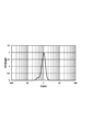
- mercury porosimetry measurement provides not only cumulative pore volume but also information on pore distribution with -dV/d (log D) on the vertical axis and D on the horizontal axis.
- V is the volume of injected mercury per sample weight (unit: mL/g)
- D is the pore diameter (unit: ⁇ m)
- logD is the natural logarithm of D
- d is the differential symbol.
- -dV/d (log D) in the pore distribution indicates the pore volume of pores with a pore diameter of D.
- the present invention proposes a catalyst with high selectivity and high yield of the target product.
- the present invention relates to 1) to 9) below.
- the catalyst (B/A) is 0.20 or more and 13.0 or less (V is the volume of mercury injected per sample weight (unit: mL/ g), D is the pore diameter (unit: ⁇ m), logD is the natural logarithm of D, -dV / d (logD) is the value obtained by differentiating the cumulative pore volume in a specific pore diameter range with the logarithm of the pore diameter ). 2)
- the catalyst of the present invention is very effective in improving the raw material conversion rate and yield while maintaining sufficient mechanical strength in the gas-phase catalytic oxidation reaction.
- the catalyst of the present invention has a pore volume distribution (-dV/d (log D) vs D) measured by a mercury intrusion method, and the -dV/d (log D) in the pore diameter range of 0.45 to 10.0 ⁇ m.
- A is the maximum value
- B is the maximum value of -dV/d (logD) in the pore diameter range of 0.040 to 0.45 ⁇ m
- (B/A) is 0.20 or more and 13.0 or less. It is characterized by Note that V is the volume of injected mercury per sample weight (unit: mL/g), D is the pore diameter (unit: ⁇ m), logD is the natural logarithm of D, and d is the differential symbol.
- the pore diameter and pore volume in the present invention are obtained by measuring by a mercury intrusion method using a porosimeter.
- the mercury intrusion method applies pressure to mercury with high surface tension and injects it into pores or gaps on the surface of a solid. is obtained, and based thereon, the pore diameter and the pore volume are obtained.
- a specific measurement method for example, without performing pretreatment such as vacuum degassing on the catalyst, using a fully automatic pore size distribution analyzer (for example, Anton Paar's mercury intrusion pore size analyzer Pore Master 60-GT).
- a sample weight of about 5 g is placed in a large cell (10 mm ⁇ 6 cm) with a cell volume of 2 cc, the cell is filled with mercury, and the mercury pressure and the volume of mercury filled in the pores are measured.
- the surface tension of mercury is set to 480 dyn/cm
- the contact angle of mercury is set to 140°
- the measurement temperature is set to 20° C.
- the range of pore diameters to be measured is set to 0.0036 ⁇ m to 400 ⁇ m.
- the cumulative specific surface area S is the specific surface area distribution ( ⁇ dS/d (logD) vs. D) and then integrating this over the entire pore size range. Specifically, from the numerical data of -dV/d (logD) at each pore diameter D of the above-mentioned pore distribution (-dV/d (logD) vs D), -dS/d (logD) Calculate In the following formula, Di is described to clarify that it is a calculation formula for a specific pore diameter, and the subscript i means the number of measurement points in the mercury intrusion method, starting from 1 and up to the number of measurement points.
- the catalysts of the present invention have specific ratios for -dV/d (log D) (units: mL/g) over a specific range of pore diameters.
- V is the volume of mercury injected per sample weight (unit: mL/g)
- D is the pore diameter (unit: ⁇ m)
- -dV/d (log D) is the cumulative total over a specific pore diameter range. It is the reciprocal of the value obtained by differentiating the pore volume with the logarithm of the pore diameter. That is, ⁇ dV/d(logD) can be considered as an index representing the pore volume distribution at a specific pore diameter D.
- the pore diameter range of 0.45 to 10.0 ⁇ m and the pore diameter range of 0.040 to 0.45 ⁇ m as the specific ranges. Then, the maximum value of -dV / d (logD) in the pore diameter range of 0.45 to 10.0 ⁇ m is A, and -dV / d (logD) in the pore diameter range of 0.040 to 0.45 ⁇ m Express the maximum value as B.
- the catalyst of the present invention has at least one It has a peak and (B/A) is 0.20 or more and 13.0 or less.
- the advantage of focusing on this pore diameter range is that the pores derived from the primary particles in the 0.040-0.45 ⁇ m pore size region and the secondary particles derived from the 0.45-10.0 ⁇ m pore size region.
- the pores each have a sharp pore distribution shape, and the catalytic performance can be improved by controlling the ratio of the maximum value in each pore diameter region within a certain range.
- the pore distribution derived from the primary particles and the pore distribution derived from the secondary particles have the same distribution shape, or the pores derived from the primary particles and the pores derived from the secondary particles have the same extent. .
- the shape and pore diameter of the pores derived from the primary particles are derived from the dispersed particles formed in the preparation liquid in the preparation step described later, and the shape and pore diameter of the pores derived from the secondary particles are It originates from the catalyst precursor formed in the drying step described below. That is, in the present invention, the pore distribution of the primary particles and the pore distribution of the secondary particles are adjusted by controlling the blending process and the drying process as described later, leading to the expression of the desired catalyst performance. is.
- the numerical range of (B/A) from 0.20 to 13.0 is also obtained by devising the composition and production method, and is a numerical range that is not satisfied with known catalysts.
- the catalyst of the present invention has a unique pore distribution shape that can only be achieved by controlling the preparation process and drying process described later. It is for
- the upper limit of (B/A) is, in order of preference, 10.0, 8.0, 6.0, 4.0, 2.0, 1.8, 1.7, 1.6, 1.5, 1. 2, 1.0, and particularly preferably 0.9.
- the lower limits are 0.3, 0.4 and 0.5 in the order of preference, and 0.6 is particularly preferred.
- the range of (B/A) is preferably 0.2 or more and 10.0 or less, 0.2 or more and 8.0 or less, 0.2 or more and 6.0 or less, 0.2 or more and 4.0 or less, 0 .2 or more and 2.0 or less, 0.2 or more and 1.8 or less, 0.2 or more and 1.7 or less, 0.2 or more and 1.6 or less, 0.3 or more and 1.5 or less, 0.4 or more and 1. 2 or less, 0.5 or more and 1.0 or less, and the most preferable range is 0.6 or more and 0.9 or less.
- the preferred range of the maximum value (A) of ⁇ dV/d (logD) in the pore diameter range of 0.45 to 4.0 ⁇ m is 0.01 or more and 1.90 or less.
- the lower limit is 0.02, 0.05, 0.10, 0.15, 0.20, 0.25 and 0.30 in the order of preference, and 0.35 is particularly preferred. Therefore, the more preferable range is from 0.02 to 1.90, from 0.05 to 1.90, from 0.10 to 1.90, from 0.15 to 1.75, and from 0.20 to 1.00. 50 or less, 0.25 or more and 1.25 or less, 0.30 or more and 1.00 or less, and the most preferable range is 0.35 or more and 0.90 or less.
- the preferred range of the maximum value (B) of ⁇ dV/d (logD) in the range of 0.040 to 0.45 ⁇ m is 0.01 or more and 1.00 or less, and the more preferred upper limit is 0.90, 0.80, 0.70, 0.60, particularly preferably 0.50.
- the lower limits are 0.05, 0.10, 0.15, 0.18, 0.19 and 0.20 in the order of preference, and 0.23 is particularly preferred. Therefore, the more preferable range is from 0.05 to 1.00, from 0.10 to 1.00, from 0.15 to 0.90, from 0.18 to 0.80, and from 0.19 to 0.19. 70 or less, 0.20 or more and 0.60 or less, and the most preferable range is 0.23 or more and 0.50 or less.
- the catalyst of the present invention has at least one peak each in the pore size range of 0.040 to 0.30 ⁇ m and the pore size range of 0.30 to 10.0 ⁇ m in the differential pore volume distribution (dV / dD vs D).
- dV / dD differential pore volume distribution
- D D
- V is the volume of injected mercury per sample weight (unit: mL/g)
- D is the pore diameter (unit: ⁇ m)
- d represents a differential symbol.
- the unit of dV/dD is mL/(g ⁇ m).
- the upper limit of (D / C) is 500.00, 100.00, 75.00, 50.00, 25.00, 10.00, 5.00, 4.50 in the order of preference, particularly preferably 4 .20.
- the lower limits are 0.05, 0.10, 0.20 and 0.30 in the order of preference, and 0.40 is particularly preferred. Therefore, the range is from 0.01 to 500.00, from 0.01 to 100.00, from 0.01 to 75.00, from 0.01 to 50.00, and from 0.05 to 25.00 in the preferred order.
- the preferred range of the maximum value (C) of dV/dD in the range of 0.30 to 10.0 ⁇ m is 0.01 or more and 100.00 or less, and the more preferred upper limits are 50.00, 10.00, 5.00, 2.50, 1.20, 1.10, 1.00, 0.90, 0.80, 0.70, and particularly preferably 0.65. Further, the lower limit is 0.02 and 0.05 in the preferred order, and 0.06 is particularly preferred.
- the more preferable ranges are 0.01 to 50.00, 0.01 to 10.00, 0.01 to 5.00, 0.01 to 2.50, and 0.01 to 1.00. 20 or less, 0.01 or more and 1.10 or less, 0.01 or more and 1.00 or less, 0.01 or more and 0.90 or less, 0.02 or more and 0.80 or less, 0.05 or more and 0.70 or less,
- the most preferable range is 0.06 or more and 0.65 or less.
- the preferred range of the maximum value (D) of dV/dD in the pore diameter range of 0.040 to 0.30 ⁇ m is 0.01 or more and 100.00 or less, and the more preferred upper limits are 50.00 and 10, respectively.
- the lower limit is 0.02, 0.05, 0.10, 0.15, 0.20 and 0.25 in the order of preference, and 0.30 is particularly preferred. Therefore, the more preferable ranges are 0.01 to 50.00, 0.01 to 10.00, 0.01 to 5.00, 0.02 to 2.50, and 0.05 to 1.00. 90 or less, 0.10 or more and 1.50 or less, 0.15 or more and 1.00 or less, 0.20 or more and 0.75 or less, 0.25 or more and 0.50 or less, and the most preferable range is 0.30 or more and 0 .45 or less.
- the catalyst of the present invention has at least one peak each in the pore size range of 0.040 to 0.35 ⁇ m and the pore size range of 0.35 to 100.0 ⁇ m in the differential pore volume distribution (dV vs D), And when the maximum value of dV in the pore diameter range of 0.35 to 100.0 ⁇ m is E and the maximum value of dV in the pore diameter range of 0.040 to 0.35 ⁇ m is F, (F / E) is 0.23 It is preferable that it is not less than 1000.00 and not more than 1000.00.
- dV represents the mercury intrusion volume (unit: mL/g) per sample weight in each measurement section measured by the mercury intrusion method.
- the upper limit of (F/E) is, in order of preference, 500.00, 100.00, 75.00, 50.00, 25.00, 10.00, 5.00, 4.50, 3.00, 2. 50, particularly preferably 2.35.
- the lower limits are 0.25, 0.30, 0.40 and 0.50 in the order of preference, with 0.54 being particularly preferred. Therefore, the more preferable range of (F/E) is 0.23 or more and 500.00 or less, 0.23 or more and 100.00 or less, 0.23 or more and 75.00 or less, 0.23 or more and 50.00 or less, 0.23 to 25.00, 0.23 to 10.00, 0.25 to 5.00, 0.30 to 4.50, 0.40 to 3.00, 0.50 to 2 0.50 or less, and the most preferable range is 0.54 or more and 2.35 or less.
- a preferred range of the maximum value of dV(E) in the range of 0.35 to 100.0 ⁇ m is 0.0001 or more and 0.5000 or less, and more preferred upper limits are 0.2500, 0.1000, 0.2500, 0.1000, 0.5000 or less. 0500, 0.0250, 0.0200, 0.0150, 0.0100, 0.0050, 0.0045, 0.0040, and particularly preferably 0.0035. Further, the lower limit is 0.0002, 0.0003 in the preferred order, and 0.0005 is particularly preferred. Therefore, the range is from 0.0001 to 0.2500, from 0.0001 to 0.1000, from 0.0001 to 0.0500, from 0.0001 to 0.0250, from 0.0001 to 0.0001, and from 0.0001 to 0.0250.
- the most preferable range is from 0.0005 to 0.0035.
- the preferred range of the maximum value of dV(F) in the range of pore diameters of 0.040 to 0.35 ⁇ m is 0.0001 or more and 0.5000 or less, and the more preferred upper limits are 0.2500 and 0.1000, respectively. , 0.0500, 0.0250, 0.0200, 0.0150, 0.0100, 0.0050, 0.0040, 0.0030, and particularly preferably 0.0020.
- the lower limits are 0.0002, 0.0005, 0.0008 and 0.0010 in the preferred order, and 0.0012 is particularly preferred. Therefore, the range is from 0.0001 to 0.2500, from 0.0001 to 0.1000, from 0.0001 to 0.0500, from 0.0001 to 0.0250, from 0.0001 to 0.0001, and from 0.0001 to 0.0250. 0200 or less, 0.0001 or more and 0.0150 or less, 0.0002 or more and 0.0100 or less, 0.0005 or more and 0.0050 or less, 0.0008 or more and 0.0040 or less, 0.0010 or more and 0.0030 or less, The most preferable range is 0.0012 or more and 0.0020 or less.
- the catalyst of the present invention has a cumulative specific surface area of less than 5.0 m 2 /g.
- a catalyst having a cumulative specific surface area of less than 5.0 m 2 /g has a drawback that the reaction rate decreases, resulting in a decrease in yield. ing.
- a catalyst with a small cumulative specific surface area can be expected to have increased catalyst strength.
- the present invention adopts a specific numerical range for the above (B/A) and realizes this range from the viewpoint of composition and production method, and the drawback is not solved even if the cumulative specific surface area is less than 5.0 m 2 /g. It has been successfully overcome and even taken advantage of.
- Preferred upper limits of the cumulative specific surface area are 4.5 m 2 /g, 4.0 m 2 /g, 3.5 m 2 /g, 3.3 m 2 /g, 3.0 m 2 /g, 2.7 m 2 / g, 2.5 m 2 /g, particularly preferably 2.0 m 2 /g.
- the lower limit can be assumed to be about 1.0 m 2 /g, but the preferred lower limits are 1.1 m 2 /g, 1.2 m 2 / g, 1.3 m 2 /g and 1.4 m 2 /g in order. , particularly preferably 1.5 m 2 /g.
- the preferred ranges of the cumulative specific surface area are, in order, 1.1 m 2 /g or more and 4.5 m 2 /g or less, 1.1 m 2 /g or more and 4.0 m 2 /g or less, 1.1 m 2 /g or more3.
- Methods for changing the pore volume parameter include adjusting the pH in the preparation process and setting the temperature in the drying process, but a particularly effective method is adjusting the pH in the preparation process.
- Adjustment of pH That is, in the preparation step of adding each supply source compound containing molybdenum, bismuth and iron to a solvent or solution, integrating and heating to obtain a prepared solution, the pH of the prepared solution is adjusted to 1.0 to 1.0 before the iron raw material is added. This is a method of adjusting to the range of 7.5. Methods for adjusting the pH include a method of lowering the pH by adding nitric acid or the like, and a method of raising the pH by adding aqueous ammonia or the like, which will be described later in detail.
- the lower limit of the pH of the prepared solution is more preferably 1.5, and further preferably 1.8, 2.0, 2.2, 2.5, 2.7, 3.0, 3.1, 3.0, 1.8, 2.0, 2.2, 2.5, 2.7, 3.0, 3.1, 3.5. 2, 3.5, 3.7, 3.8, 3.9. If the pH of the prepared solution is lower than 3.0, precipitates and gels are generated in the prepared solution, and there is a risk of clogging in the nozzle of the spray dryer in the drying process described later. The control can change the pore structure and also avoid the issue of spray plugging.
- the upper limit of the pH of the prepared solution is more preferably 7.3, and further preferably 7.0, 6.7, 6.5, 6.3, 6.1, 6.0, 5.9, 5 in order of preference. .8, 5.5, 5.3, 5.0, 4.8, 4.5. That is, the range of the pH value of the preparation solution is, in order of preference, 1.5 to 7.3, 1.5 to 7.0, 1.8 to 6.7, 2.0 to 6.5, 2.2 to 6.3, 2.5 to 6.1, 2.7 to 6.0, 3.0 to 5.9, 3.1 to 5.8, 3.2 to 5 0.5 or less, 3.5 or more and 5.3 or less, 3.7 or more and 5.0 or less, 3.8 or more and 4.8 or less, and most preferably 3.9 or more and 4.5 or less.
- the pH may fall within the above range without adding a pH adjuster before adding the iron raw material.
- the purpose is to adjust the pH within the above range.
- the pH adjuster in the method of lowering the pH, in addition to acids for pH adjustment that are generally used as catalyst raw materials by those skilled in the art, such as nitric acid, sulfuric acid, hydrochloric acid, and oxalic acid, elements of the catalytically active components described later Phosphoric acid, boric acid, molybdic acid, iron nitrate, and other pH adjusters whose elements remain after firing are included as long as they do not change the composition, but nitric acid is most preferred.
- the most preferable embodiment is to prepare a slurry in the order of adding the iron raw material, stirring the mixture, and then adding the bismuth raw material to the prepared solution.
- the lower limit of the stirring power is preferably 0.05 kw/m 3 , 0.10 kw/m 3 , 0.50 kw/m 3 and 1.00 kw/m 3
- the upper limit of the stirring power is preferably 4.50 kw/m 3 . , 4.00 kw/m 3 , 3.50 kw/m 3 , 3.00 kw/m 3 .
- the range of stirring power is 0.050.05 to 4.50 kw/m 3 , 0.10 to 4.00 kw/m 3 , 0.50 to 3.50 kw/m 3 in order of preference, and most preferably 1.0 kw/m 3 . 00 to 3.00 kw/ m3 .
- the dropping time of the pH adjuster is between 1 second and 5 minutes.
- the lower limit of the dropping time is preferably 5 seconds, 10 seconds and 15 seconds
- the upper limit of the dropping time is preferably 4 minutes, 3 minutes, 2 minutes 30 seconds, 2 minutes, 1 minute 30 seconds, 1 minute and 45 seconds. 30 seconds.
- the range of dropping time is, in order of preference, 5 seconds to 4 minutes, 5 seconds to 3 minutes, 5 seconds to 2 minutes 30 seconds, 5 seconds to 2 minutes, 5 seconds to 1 minute 30 seconds, 5 seconds to 1 minute, 10 seconds ⁇ 45 seconds, most preferably 15-30 seconds.
- the liquid temperature of the prepared liquid when the pH adjuster is dropped is 5 to 80°C.
- the lower limits of the liquid temperature are preferably 10°C, 20°C and 30°C
- the upper limits of the liquid temperature are preferably 70°C, 60°C, 50°C and 40°C. That is, the liquid temperature range is, in order of preference, 10 to 70°C, 10 to 60°C, and 20 to 50°C, most preferably 30 to 40°C.
- one method for obtaining the catalyst of the present invention is to adjust the pH in the preparation process, but another effective method is optimization of the rotation speed of the atomizer (rotary atomizer) in the case of spray drying.
- the optimum number of rotations of a rotary atomizer cannot be generalized because it is affected by the structure of the rotary atomizer and the spray dryer, the temperature, pH, and viscosity of the liquid to be dried, and the blending ratio of the catalyst constituents, but it is preferable. It is 10,000 rpm or more and 18,000 rpm or less. More preferably, the upper limit of the rotational speed of the rotary atomizer is 17,000 rpm, particularly preferably 16,000 rpm, and most preferably 15,000 rpm.
- a more preferred lower limit is 11,000 rpm, a particularly preferred lower limit is 12,000 rpm, and the most preferred lower limit is 13,000 rpm. That is, the range of rotation speed of the rotary atomizer is more preferably 11,000 rpm to 17,000 rpm, 12,000 rpm to 16,000 rpm, and most preferably 13,000 rpm to 15,000 rpm.
- the number of revolutions of the atomizer is also expressed by the relative centrifugal acceleration, and is preferably 6000G or more and 20000G or less. More preferable lower limits are 7500G, 8500G and 10000G in order, and more preferable upper limits are 18000G, 16000G and 14000G in order.
- the range of rotation speed of the rotary atomizer is more preferably 7500G or more and 18000G or less, 8500G or more and 16000G or less, and most preferably 10000G or more and 14000G or less.
- the inlet temperature of the atomizer for spray drying is preferably 180°C or higher and 320°C or lower. More preferred lower limits are 200°C, 220°C and 230°C in order, and more preferred upper limits are 300°C, 280°C and 270°C in order. More preferably, the inlet temperature is 200°C or higher and 300°C or lower, 220°C or higher and 280°C or lower, and most preferably 230°C or higher and 270°C or lower.
- the outlet temperature of the atomizer for spray drying is preferably 100° C. or higher and 150° C. or lower. More preferred lower limits are 101°C, 102°C, 103°C, 104°C and 105°C in order, and more preferred upper limits are 140°C, 130°C and 120°C in order. That is, the more preferable ranges for the outlet temperature are 101°C to 150°C, 102°C to 150°C, 103°C to 140°C, 104°C to 130°C, and most preferably 105°C to 120°C. . Furthermore, the difference between the inlet temperature and the outlet temperature is preferably 30°C or higher and 220°C or lower.
- More preferable lower limits are 50°C, 80°C, 100°C and 120°C in order, and more preferable upper limits are 200°C, 180°C, 165°C and 150°C in order. More preferably, the difference between the inlet temperature and the outlet temperature is 50°C to 200°C, 80°C to 180°C, 100°C to 165°C, and most preferably 120°C to 150°C.
- the range of the parameter SD given by the following formula in the method for producing the catalyst of the present invention is preferably 22 or more and 51 or less. More preferred lower limits are 26, 28, 30, 32, 34 and 35 in order, and more preferred upper limits are 48, 44, 42 and 40 in order.
- the more preferable range of SD is from 26 to 51, from 28 to 51, from 30 to 48, from 32 to 44, from 34 to 42, and most preferably from 35 to 40.
- SD 51.3 + 0.0766 x ⁇ (spray dryer inlet temperature, unit: °C) - (spray dryer outlet temperature, unit: °C) ⁇ - 0.00173 x (atomizer rotation speed, unit: rpm) That is, the catalyst of the present invention can be obtained by appropriately controlling the pH in the preparation step and the drying conditions in the drying step. Furthermore, the catalyst of the present invention can also be obtained by combining other methods described below as necessary.
- e1/b1 is 0.10 to 4.00, 0 .50 to 4.00, 1.00 to 4.00, 1.40 to 4.00, 1.50 to 4.00, 1.70 to 4.00, 1.90 to 3.00 50 or less, 2.00 or more and 3.00 or less.
- the upper limits of d1/b1 are 12.0, 11.0, 10.0 and 9.5 in the order of preference, and the lower limits of d1/b1 are 2.0, 3.0, 4.0, 5.0 and 2.0 in the order of preference.
- d1/b1 is 2.0 or more and 12.0 or less, 3.0 or more and 12.0 or less, 4.0 or more in order of preference. 12.0 or less, 5.0 or more and 12.0 or less, 5.5 or more and 12.0 or less, 6.0 or more and 11.0 or less, 6.5 or more and 10.0 or less, 7.0 or more and 9.5 or less be.
- the upper limits of c1/e1 are 4.0, 3.0, 2.5, 2.0, and 1.7 in the order of preference, and the lower limits of c1/e1 are in the order of preference 0.1, 0.4, 0.4, 0.1, 0.4, 0.1, 0.4, 0.1, 0.4, 0.1, 0.4, 0.1, 0.4, 0.1, 0.4, 0.1, 0.4, 0.1, 0.4, 0.1, 0.4, 0.1, 0.4, 0.1, 0.4, 0.1, 0.4, 0.1, 0.4, 0.1, 0.4, 0.1, 0.4, 0.1, 0.4, 0.4, 0.1, 0.4, 0.1, 0.4, 0.4, 0.1, 0.4, 0.1, 0.4, 0.1, 0.4, 0.1, 0.1, 0.4, 0.4, 0.1, 0.1, 0.4, 0.4, 0.1, 0.4, 0.1, 0.1, 0.4, 0.4, 0.1, 0.4, 0.1, 0.4, 0.4, 0.1, 0.4, 0.1, 0.4
- c1/e1 is 0.1 or more and 4.0 or less, 0.1 or more and 3.0 or less, 0.4 or more and 2.5 or less, 0.6 or more and 2.0 in order of preference. Below, it is 0.8 or more and 1.7 or less.
- the upper limit of c1/d1 is 2.0, 1.0, 0.8, 0.6 in the order of preference, and the lower limit of c1/d1 is 0.1, 0.2 in the order of preference.
- the ranges are 0.1 to 2.0, 0.1 to 1.0, 0.1 to 0.8, and 0.2 to 0.6 in order of preference.
- the upper limit of g1/d1 is 0.100, 0.050, 0.040, 0.030, 0.020 and 0.015 in the order of preference, and the lower limit of g1/d1 is 0.001, 0.015 in the order of preference. 002, 0.003, 0.004, and 0.005, and the range of g1/d1 is 0.001 or more and 0.100 or less, 0.001 or more and 0.050 or less, and 0.002 or more and 0.040 or less in order of preference. , 0.003 to 0.030, 0.004 to 0.020, and 0.005 to 0.015.
- the firing temperature is 200° C. or higher and 600° C. or lower, preferably 300° C. or higher and 550° C. or lower, more preferably 460° C. or higher and 550° C. or lower in both the preliminary firing and the main firing described later, and both of them.
- the firing time is 0.5 hours or more, preferably 1 hour or more and 40 hours or less, more preferably 2 hours or more and 15 hours or less, and most preferably 2 hours or more and 9 hours or less.
- the firing atmosphere has an oxygen concentration of 10% by volume or more and 40% by volume or less, preferably 15% by volume or more and 30% by volume or less, most preferably an air atmosphere.
- the temperature of the catalyst surface from the highest temperature (pre-calcination temperature or main-calcination temperature) during the calcination process to room temperature.
- the rate of decrease is 1°C/min or more and 200°C/min or less, preferably 5°C/min or more and 150°C/min or less, more preferably 10°C/min or more and 120°C/min or less, most preferably 50 °C/min or more and 100°C/min or less.
- a temperature-lowering method generally taken industrially, for example, a method of exposing the calcined catalyst removed from the calcining furnace to an inert atmosphere or a mist of an inert solvent, or a method of sufficiently cooling in advance Any technique for rapidly moving the calcined catalyst into the chamber is within the scope of the practice of this invention.
- Method (IV) is a method of controlling the application of mechanical impact, shear stress, etc. to the catalyst precursor and/or granules formed in each step, which will be described later. In this method, the mechanical impact, shear stress, etc.
- the details are not limited as long as it uses reagent-grade high-purity raw materials.
- the total content of sulfur and its compounds, lithium, halogens and their compounds, and lead is A feedstock that is below 1000 ppm by weight, preferably below 1000 ppm by weight, more preferably below 100 ppm by weight, and most preferably below 10 ppm by weight is used.
- the catalyst precursor is once obtained as granules and then molded, as will be described later. By obtaining the catalyst precursor as granules, each component of the catalyst can be produced more uniformly.
- method (VII) in the catalyst blending process described later, the cobalt raw material and the nickel raw material are mixed, reacted, slurried, and retained in the blending vessel for as short a time as possible. is a method for shortening the residence time after mixing the aqueous metal salt solution derived from molybdenum and alkali metals and the aqueous metallic salt solution derived from cobalt and nickel in the mixing pot, or specifying the pH in the mixing pot as described above.
- the retention time after charging the aqueous metal salt solution derived from cobalt and nickel into the mixing vessel is shortened.
- the residence time is preferably 24 hours, more preferably 1 hour, still more preferably 30 minutes, and most preferably 10 minutes.
- the above pH range is from 1 to 14, preferably from 2 to 10, more preferably from 2 to 8, and most preferably from 3 to 7.
- the method (VIII) there is a method in which each raw material is added all at once without being divided in the catalyst preparation step described later, or a method in which the concentration of nitric acid in the prepared solution is lowered.
- the above method of charging all at once means charging the next raw material after all the required amounts of each raw material have been charged.
- the concentration of nitrate ions in the prepared solution at the time of proceeding to the next step after completion of preparation is preferably 40% by mass or less, more preferably 35% by mass. below, more preferably 30% by mass or less, most preferably 25% by mass or less.
- the catalyst of the present invention preferably contains molybdenum, bismuth and iron, and more preferably has a composition represented by the following formula (1).
- Mo a1 Bi b1 Ni c1 Co d1 Fe e1 X f1 Y g1 Z h1 O i1 (1)
- Mo, Bi, Ni, Co and Fe represent molybdenum, bismuth, nickel, cobalt and iron respectively
- X represents tungsten, antimony, tin, zinc, chromium, manganese, magnesium, calcium, silicon, aluminum, cerium and at least one element selected from titanium
- Y is at least one element selected from sodium, potassium, cesium, rubidium, and thallium
- Z belongs to groups 1 to 16 of the periodic table
- Mo, Bi means at least one element selected from elements other than Ni, Co, Fe, X, and Y, and a1, b1, c1, d1, e1, f1, g1, h1, and i1 are molyb
- the lower limit of b1 is 0.1, 0.2, 0.3, 0.4, 0.5 and 0.6 in the preferred order, and the upper limit is 6.0, 5.0, 4.0 in the preferred order. 0, 3.0, 2.0, 1.8, 1.5, 1.2, 1.0, 0.9.
- the range of b1 is 0.1 or more and 6.0 or less, 0.1 or more and 5.0 or less, 0.1 or more and 4.0 or less, 0.1 or more and 3.0 or less, 0.1 or more and 2 0.0 or less, 0.2 or more and 1.8 or less, 0.3 or more and 1.5 or less, 0.4 or more and 1.2 or less, 0.5 or more and 1.0 or less, and the most preferable range is 0.6 0.9 or less.
- the lower limit of c1 is 0.1, 0.2, 0.3, 0.5, 0.7, 0.9, 1.1, 1.3, and 1.5 in the preferred order, and the upper limit is preferred. In order, they are 8.0, 7.0, 6.0, 5.0, 4.0, 3.5, 3.3.
- the range of c1 is, in order of preference, 0.1 to 8.0, 0.2 to 8.0, 0.3 to 8.0, 0.5 to 8.0, 0.7 to 8 0.0 or less, 0.8 or more and 7.0 or less, 0.9 or more and 6.0 or less, 1.0 or more and 5.0 or less, 1.1 or more and 4.0 or less, 1.3 or more and 3.5 or less , the most preferred range is from 1.5 to 3.3.
- the lower limits of d1 are 1.0, 2.0, 3.0, 4.0, 5.0 and 5.4 in the preferred order, and the upper limits are 10.0, 9.5 and 9.5 in the preferred order. 0, 8.5, 8.0, 7.5, 7.0.
- the range of d1 is, in order of preference, 1.0 to 10.0, 1.0 to 9.5, 2.0 to 9.0, 3.0 to 8.5, 4.0 to 8 0.0 or less, 5.0 or more and 7.5 or less, and the most preferable range is 5.4 or more and 7.0 or less.
- the lower limits of c1+d1 are 1.1, 2.0, 4.0, 6.0, 7.0 and 7.8 in preferred order, and the upper limits are 20.0, 15.0, 12.0 and 12.0 in preferred order. 5, 11.0, 10.0, 9.5.
- the range of c1 + d1 is, in order of preference, 1.1 or more and 20.0 or less, 2.0 or more and 15.0 or less, 4.0 or more and 12.5 or less, 6.0 or more and 11.0 or less, 7.0 or more It is 10.0 or less, and the most preferable range is 7.8 or more and 9.5 or less.
- the lower limit of e1 is 0.1, 0.2, 0.5, 0.8, 1.0, 1.5, 1.6 and 1.7 in the preferred order, and the upper limit is 5.0 in the preferred order. 0, 4.5, 4.0, 3.5, 3.0, 2.5, 2.2.
- the range of e1 is, in order of preference, from 0.1 to 5.0, from 0.2 to 5.0, from 0.5 to 4.5, from 0.8 to 4.0, and from 1.0 to 3. 0.5 or less, 1.5 or more and 3.0 or less, 1.6 or more and 2.5 or less, and the most preferable range is 1.7 or more and 2.2 or less.
- the upper limit of f1 is 1.8, 1.5, 1.0, 0.8 and 0.5 in order of preference, and the lower limit is preferably 0. That is, the range of f1 is from 0 to 1.8, from 0 to 1.5, from 0 to 1.0, from 0 to 0.8, and from 0 to 0.5 in the preferred order. is 0.
- the lower limits of g1 are 0.01, 0.02 and 0.03 in the preferred order, and the upper limits are 2, 1, 0.5, 0.4, 0.3, 0.2, 0.2 and 0.3 in the preferred order. 15, 0.09. That is, the range of g1 is 0.01 or more and 2 or less, 0.01 or more and 1 or less, 0.01 or more and 0.5 or less, 0.01 or more and 0.4 or less, 0.01 or more and 0.3 or less, 0 0.01 or more and 0.2 or less, 0.02 or more and 0.15 or less, and the most preferable range is 0.03 or more and 0.09 or less.
- the upper limit of h1 is 4.0, 3.0, 2.0, 1.8, 1.5, 1.0, 0.8 and 0.5 in order of preference, and the lower limit is preferably 0.
- the range of h1 is preferably 0 to 4.0, 0 to 3.0, 0 to 2.0, 0 to 1.8, 0 to 1.5, 0 to 1.0, 0 or more and 0.8 or less, 0 or more and 0.5 or less, and most preferably h1 is 0.
- X in formula (1) is preferably tungsten, antimony, zinc, magnesium, calcium or cerium, and particularly preferably antimony or zinc.
- Y in formula (1) is preferably sodium, potassium, or cesium, more preferably potassium or cesium, and particularly preferably potassium.
- Z in Formula (1) is preferably phosphorus.
- the drying temperature is not particularly limited as long as it can remove moisture, and when adjusting the pressure and time, normal temperature (25° C.) may be used. However, the drying temperature is preferably 80° C. or higher, more preferably 90° C. or higher, in order to more reliably remove moisture in a short period of time. When the pressure is not adjusted, the drying temperature is preferably 100°C or higher, more preferably 150°C or higher. As the preliminary firing, firing is performed at a temperature of about 200.degree. C. to 600.degree. C. for about 1 to 12 hours. There are no particular restrictions on the atmosphere during firing and the rate of temperature increase within the range known to those skilled in the art. The atmosphere is a compound atmosphere, and the rate of temperature increase is 0.01° C./min or more and 10° C./min or less.
- a catalyst in which a pre-calcined powder that has been pre-calcined after catalyst preparation is supported on an inert carrier is particularly effective as the catalyst of the present invention.
- the material of the inert carrier known materials such as alumina, silica, titania, zirconia, niobia, silica alumina, silicon carbide, carbide, and mixtures thereof can be used.
- the crystallinity of the crystalline phase and the mixing ratio are not particularly limited, either, and an appropriate range should be selected in consideration of the final catalyst performance, moldability, production efficiency, and the like.
- the mixing ratio of the carrier and the pre-calcined powder is calculated as the loading rate from the following formula according to the charged mass of each raw material.
- Support rate (mass of pre-fired powder used for molding)/ ⁇ (mass of pre-fired powder used for molding) + (mass of carrier used for molding) ⁇ x 100
- a preferable upper limit of the loading rate is 80% by mass, more preferably 60% by mass.
- a preferred lower limit is 20% by mass, more preferably 30% by mass. That is, the preferable range of the loading ratio is 20% by mass or more and 80% by mass or less, and the most preferable range is 30% by mass or more and 60% by mass or less.
- the inert carrier silica and/or alumina are preferred, and a mixture of silica and alumina is particularly preferred.
- binders that can be used include water, ethanol, methanol, propanol, polyhydric alcohols, polymeric binder polyvinyl alcohol, and inorganic binder silica sol aqueous solutions.
- diols such as ethylene glycol and triols such as glycerin are preferred, and an aqueous solution of glycerin having a concentration of 5% by mass or more is preferred.
- the amount of these binders to be used is usually 2 to 60 parts by mass with respect to 100 parts by mass of the pre-fired powder.
- the binder and the pre-fired powder may be supplied to the molding machine alternately or simultaneously.
- molybdenum components include molybdenum oxides such as molybdenum trioxide, molybdic acid, ammonium paramolybdate, and metamolybdenum.
- Molybdic acid such as ammonium acid or its salt, heteropolyacid containing molybdenum such as phosphomolybdic acid, silicomolybdic acid or its salt can be used.
- bismuth salts such as bismuth nitrate, bismuth carbonate, bismuth sulfate, bismuth acetate, bismuth trioxide, and bismuth metal can be used.
- These raw materials can be used as solids or in the form of aqueous solutions, nitric acid solutions, or slurries of bismuth compounds produced from these aqueous solutions, but it is preferred to use nitrates, their solutions, or slurries produced from these solutions.
- Starting materials for other component elements include ammonium salts, nitrates, nitrites, carbonates, subcarbonates, acetates, chlorides, inorganic acids, and inorganic acid salts of metal elements generally used in this type of catalyst.
- heteropolyacids, salts of heteropolyacids, sulfates, hydroxides, organic acid salts, oxides, or mixtures thereof may be used in combination, and ammonium salts and nitrates are preferably used.
- the compounds containing these active ingredients may be used alone, or two or more of them may be mixed and used.
- a slurry liquid can be obtained by uniformly mixing each active ingredient-containing compound and water.
- the amount of water used in the slurry liquid is not particularly limited as long as it can completely dissolve the entire amount of the compounds used or can be uniformly mixed.
- the amount of water to be used may be appropriately determined in consideration of the drying method and drying conditions. Generally, the amount of water used is 100 parts by mass or more and 2000 parts by mass or less with respect to 100 parts by mass of the total mass of the slurry-preparing compounds.
- the amount of water may be large, but if it is too large, the energy cost of the drying process becomes high, and there are many demerits such as inability to dry completely.
- the slurry liquid of the supply source compound of each component element is prepared by (i) a method of collectively mixing each of the aforementioned source compounds, (ii) a method of aging treatment after collectively mixing, and (iii) stepwise It is preferably prepared by a method of mixing, (iv) a method of repeating mixing and aging treatment in stages, and a method of combining (i) to (iv).
- the above-mentioned aging means "processing industrial raw materials or semi-finished products under specific conditions such as a certain period of time and a certain temperature to acquire or increase the required physical and chemical properties or to progress a predetermined reaction.
- the above-mentioned fixed time means a range of 5 minutes or more and 24 hours or less
- the above-mentioned fixed temperature means a range of room temperature or higher and the boiling point or lower of the aqueous solution or aqueous dispersion.
- the method (iii) of stepwise mixing is preferred from the standpoint of the activity and yield of the finally obtained catalyst, and more preferred is the stepwise mixing of the raw materials with the mother liquor in a completely dissolved solution.
- the most preferred method is a method of mixing various mixed liquids of an alkali metal solution and a nitrate with a mother liquor obtained by preparing a molybdenum raw material as a prepared liquid or slurry.
- the shape of the stirring blades of the stirrer used for mixing the essential active ingredients is not particularly limited.
- Arbitrary stirring blades such as blades can be used in one stage or two or more stages of the same blade or different blades in the vertical direction.
- a baffle baffle plate
- a baffle plate may be installed in the reaction vessel as required.
- the slurry liquid thus obtained is then dried.
- the drying method is not particularly limited as long as it can completely dry the slurry liquid, and examples thereof include drum drying, freeze drying, spray drying, and evaporation to dryness.
- spray drying which can dry a slurry liquid into powder or granules in a short period of time, is particularly preferred.
- the drying temperature of the spray drying varies depending on the concentration of the slurry liquid, the liquid feeding speed, etc., but generally the temperature at the outlet of the dryer is 70° C. or more and 150° C. or less.
- the catalyst precursor obtained as described above is preliminarily calcined, molded, and then calcined, so that the molded shape can be controlled and maintained. It is obtained, and stable catalyst performance can be expressed.
- a carrier such as silica
- non-support molding without using a carrier can be adopted.
- Specific molding methods include, for example, tablet molding, press molding, extrusion molding, and granulation molding.
- shape of the molded product for example, a cylindrical shape, a ring shape, a spherical shape, or the like can be appropriately selected in consideration of the operating conditions. , an average particle size of 3.0 mm or more and 10.0 mm or less, preferably an average particle size of 3.0 mm or more and 8.0 mm or less.
- a tumbling granulation method, a method using a centrifugal fluidized coating device, a wash coating method, and the like are widely known.
- the apparatus has a flat or uneven disk at the bottom of a fixed cylindrical container.
- the powder component is supported on the carrier by vigorously stirring the mixture by repeating the movement and adding the pre-baked powder.
- a binder at the time of carrying.
- binders include water, ethanol, methanol, propanol, polyhydric alcohols, polymeric binder polyvinyl alcohol, and inorganic binder silica sol aqueous solutions.
- diols such as ethylene glycol and triols such as glycerin are more preferred, and aqueous solutions of glycerin having a concentration of 5% by mass or more are even more preferred.
- aqueous solutions of glycerin having a concentration of 5% by mass or more are even more preferred.
- the amount of these binders to be used is usually 2 to 60 parts by mass with respect to 100 parts by mass of the pre-fired powder.
- the binder and the pre-baked powder may be supplied to the molding machine alternately or simultaneously during the carrying.
- a small amount of known additives such as graphite and talc may be added. Any of the molding aid, pore-forming agent, and carrier added in the molding process can be used as constituent elements of the active ingredient in the present invention, regardless of whether or not they have activity in the sense of converting the raw material into some other product. shall not be considered.
- the preliminary firing method, preliminary firing conditions, main firing method, and main firing conditions are not particularly limited, and known treatment methods and conditions can be applied.
- Preliminary calcination or main calcination is usually carried out at 200° C. or higher and 600° C. or lower, preferably 300° C. or higher and 550° C. or lower, under circulation of an oxygen-containing gas such as air or under circulation of an inert gas, for 0.5 hours or more, preferably It is carried out for 1 hour or more and 40 hours or less.
- the inert gas means a gas that does not lower the reaction activity of the catalyst, and specific examples thereof include nitrogen, carbon dioxide, helium, argon, and the like.
- the optimum conditions particularly in the main calcination differ. Since it is known to those skilled in the art to change the oxygen content, the maximum temperature reached, the firing time, etc., it is included in the scope of the present invention.
- the main firing process is performed after the preliminary firing process described above, and the maximum temperature reached in the main firing process (main firing temperature) is higher than the maximum temperature reached in the preliminary firing process (preliminary firing temperature). be high.
- calcination method such as a fluidized bed, rotary kiln, muffle furnace, or tunnel calciner, and an appropriate range should be selected in consideration of the final catalyst performance, mechanical strength, moldability, production efficiency, etc. is.
- the catalyst of the present invention is preferably used as a catalyst for producing an unsaturated aldehyde compound, an unsaturated carboxylic acid compound, or a conjugated diene compound, and more preferably used as a catalyst for producing an unsaturated aldehyde compound. is more preferable, and it is particularly preferable to use it as a catalyst for producing acrolein from propylene.
- the reaction tube inlet side It is known to those skilled in the art to pack different catalyst species in multiple layers to increase activity from the reactor tube outlet side.
- the catalyst of the present invention can be used on either the inlet side of the reaction tube, the outlet side of the reaction tube, or the intermediate catalyst layer. It is most preferable to use it for a simple catalyst. In multi-layer packing, two-layer or three-layer packing is particularly preferred.
- the catalyst of the present invention can be used not only as a first-stage catalyst, that is, a catalyst for producing an unsaturated aldehyde compound, but also as a second-stage catalyst, that is, a catalyst for producing an unsaturated carboxylic acid compound. can be used.
- a second-stage catalyst it is preferable to use a catalyst represented by the following formula (2).
- Mo, V, W, Cu, Sb and O respectively represent molybdenum, vanadium, tungsten, copper, antimony and oxygen
- X2 is at least one element selected from the group consisting of alkali metals and thallium
- Y2 is at least one element selected from the group consisting of magnesium, calcium, strontium, barium and zinc
- Z2 is niobium, cerium, tin, chromium, manganese, iron, cobalt, samarium, germanium, titanium and arsenic.
- Each represents at least one element selected from the group consisting of: a2, b2, c2, d2, e2, f2, g2, and h2 represent the atomic ratio of each element, 0 ⁇ a2 ⁇ 10, 0 ⁇ b2 ⁇ 10; , 0 ⁇ c2 ⁇ 6, 0 ⁇ d2 ⁇ 10, 0 ⁇ e2 ⁇ 0.5, 0 ⁇ f2 ⁇ 1, and 0 ⁇ g2 ⁇ 6, and h2 satisfies the valence of each component. is the number of oxygen atoms required.).
- the catalyst represented by the above formula (2) a method generally known as a method for preparing this type of catalyst, such as an oxide catalyst, a heteropolyacid, or a catalyst having a salt structure thereof can be employed.
- the catalyst of the present invention is used as the second-stage catalyst, the above-described method for obtaining the catalyst of the present invention can be appropriately applied in the production of the catalyst.
- Raw materials that can be used in producing the catalyst are not particularly limited, and various raw materials can be used.
- molybdenum oxides such as molybdenum trioxide, molybdic acid, molybdic acid such as ammonium molybdate or salts thereof, heteropolyacids containing molybdenum such as phosphomolybdic acid, silicomolybdic acid or salts thereof can be used.
- Antimony component raw materials that can be used are not particularly limited, but antimony trioxide or antimony acetate is preferable.
- raw materials for other elements such as vanadium, tungsten and copper, respective nitrates, sulfates, carbonates, phosphates, organic acid salts, halides, hydroxides, oxides and metals can be used.
- the compounds containing these active ingredients may be used alone, or two or more of them may be mixed and used.
- a slurry liquid obtained by mixing the above raw materials in water is dried to obtain a solid catalyst precursor.
- the drying method is not particularly limited as long as the slurry liquid can be dried completely, and examples thereof include drum drying, freeze drying, spray drying, and evaporation to dryness. Spray drying, which can be carried out, is preferred.
- the drying temperature of spray drying varies depending on the concentration of the slurry liquid, the liquid feeding speed, etc., but the temperature at the inlet of the dryer is generally 140 to 400 ° C., and the temperature at the outlet is 70 to 150 ° C.
- the inlet temperature is higher than the outlet temperature. get higher Moreover, it is preferable to dry so that the average particle size of the dried slurry obtained at this time is 10 to 700 ⁇ m.
- the second-stage catalyst precursor solid obtained as described above can be used as it is in the coating mixture, but calcination may improve moldability, which is preferable.
- the firing method and firing conditions are not particularly limited, and known treatment methods and conditions can be applied.
- the optimum calcination conditions vary depending on the catalyst raw material used, catalyst composition, preparation method, etc., but the calcination temperature is usually 100 to 350° C., preferably 150 to 300° C., and the calcination time is 1 to 20 hours.
- Firing is usually carried out in an air atmosphere, but it may be carried out in an inert gas atmosphere such as nitrogen, carbon dioxide, helium, argon, etc. After firing in an inert gas atmosphere, if necessary, further Firing may be performed in an air atmosphere.
- the calcined solid thus obtained is preferably pulverized before molding. Although there are no particular restrictions on the pulverization method, it is preferable to use a ball mill.
- the compound containing the active ingredient when preparing the slurry in the second step does not necessarily contain all the active ingredients, and some of the ingredients may be used before the following molding step. .
- the second-stage catalyst there are no particular restrictions on the shape of the second-stage catalyst, and it is used after molding into a pillar, tablet, ring, sphere, etc. in order to reduce the pressure loss of the reaction gas in the oxidation reaction.
- This loading is preferably carried out by the tumbling granulation method described below. In this method, for example, in an apparatus having a flat or uneven disk at the bottom of a fixed container, the disk is rotated at high speed to vigorously stir the carrier in the container by repeating rotation and revolution.
- a binder, a catalyst precursor solid, and, if necessary, other additives such as molding aids and strength improving agents are added to a support mixture, which is supported on a carrier.
- the method of adding the binder is as follows: 1) pre-mixed with the carrier mixture, 2) added at the same time as the carrier mixture is added into the fixed container, and 3) added after the carrier mixture is added into the fixed container. 4) adding the mixture for loading before adding it into the fixed container; 5) dividing the mixture for loading and the binder respectively; .
- the addition speed is adjusted using an auto feeder or the like so that a predetermined amount of the supporting mixture is supported on the carrier without the supporting mixture adhering to the walls of the stationary container or agglomeration of the supporting mixture.
- the binder include water, ethanol, polyhydric alcohol, polyvinyl alcohol as a polymeric binder, celluloses such as crystalline cellulose, methyl cellulose and ethyl cellulose, silica sol aqueous solution as an inorganic binder, and the like.
- a diol or a triol such as glycerin is preferable, and an aqueous solution of glycerin having a concentration of 5% by mass or more is particularly preferable.
- the amount of these binders to be used is usually 2 to 60 parts by mass, preferably 10 to 50 parts by mass, per 100 parts by mass of the supporting mixture.
- the carrier for the above-mentioned support include spherical carriers having a diameter of 1 to 15 mm, preferably 2.5 to 10 mm, such as silicon carbide, alumina, silica-alumina, mullite and alundum. These carriers usually have a porosity of 10 to 70%.
- silica gel, diatomaceous earth, alumina powder, etc. are mentioned as a shaping
- the amount of molding aid to be used is generally 1 to 60 parts by mass per 100 parts by mass of the solid catalyst precursor.
- inorganic fibers for example, ceramic fibers, whiskers, etc.
- Glass fibers are preferably used.
- the amount of these fibers to be used is usually 1 to 30 parts by weight per 100 parts by weight of the solid catalyst precursor.
- the forming aid, pore-forming agent, and carrier that are added, regardless of whether they have activity in the sense of converting the raw material into some other product, It shall not be considered as a constituent element of the active ingredient in the present invention.
- the supported catalyst obtained as described above can be directly used as a catalyst for the gas-phase catalytic oxidation reaction, but calcination may improve the catalytic activity, which is preferable.
- the firing method and firing conditions are not particularly limited, and known treatment methods and conditions can be applied.
- the optimum calcination conditions vary depending on the catalyst raw material used, catalyst composition, preparation method, etc., but the calcination temperature is usually 100 to 450° C., preferably 270 to 420° C., and the calcination time is 1 to 20 hours.
- Firing is usually carried out in an air atmosphere, but it may be carried out in an inert gas atmosphere such as nitrogen, carbon dioxide, helium, argon, etc. After firing in an inert gas atmosphere, if necessary, further Firing may be performed in an air atmosphere.
- an oxidation catalyst for producing conjugated diolefins (1,3-butadiene, etc.) from a mixed gas containing monoolefins (butenes, etc.) having 4 or more carbon atoms and molecular oxygen by catalytic oxidative dehydrogenation reaction, oxidation
- the catalyst is also useful as a dehydrogenation catalyst.
- the catalyst of the present invention can be effective in improving yield even in a region where catalytic activity is particularly high or in a region where catalytic activity is not high. It is also expected to improve the process stability of the exothermic partial oxidation reaction. Additionally, the catalysts of the present invention can be effective in reducing by-products such as carbon monoxide (CO) and carbon dioxide ( CO2 ), acetaldehyde, acetic acid, and formaldehyde that adversely affect the environment and final product quality. .
- CO carbon monoxide
- CO2 carbon dioxide
- the catalyst of the present invention thus obtained can be used, for example, in the production of acrolein and/or acrylic acid by gas-phase catalytic oxidation of propylene using a molecular oxygen-containing gas.
- the method of circulating the raw material gas may be an ordinary single flow method or a recycling method, and is not particularly limited as it can be carried out under generally used conditions.
- propylene as a starting material at room temperature is 1 to 10% by volume, preferably 4 to 9% by volume, molecular oxygen is 3 to 20% by volume, preferably 4 to 18% by volume, water vapor is 0 to 60% by volume, Preferably 4 to 50% by volume, 20 to 80% by volume, preferably 30 to 60% by volume of an inert gas such as carbon dioxide, nitrogen, etc. are filled in the reaction tube.
- the reaction is carried out at 450° C. under normal pressure to 10 atm and space velocity of 300 to 5000 h ⁇ 1 .
- the term "improved catalytic activity" means that the raw material conversion rate is high when the catalytic reaction is carried out at the same reaction bath temperature and compared.
- the corresponding unsaturated aldehyde and / or unsaturated carboxylic acid It means that the total yield of Moreover, unless otherwise specified, the yield refers to the effective yield described later.
- the constituent elements of the catalyst precursor refer to all elements used in the catalyst production process, but they disappear, sublimate, volatilize, and burn at a temperature lower than the maximum temperature of the firing process.
- the raw material and its constituent elements shall not be included in the constituent elements of the active component of the catalyst.
- silicon and other inorganic material-constituting elements contained in the forming aid and carrier in the forming step shall not be included as constituent elements of the active component of the catalyst.
- the hot spot temperature is the maximum temperature of the temperature distribution in the catalyst packed bed measured by installing a thermocouple in the longitudinal direction of the multitubular reaction tube, and the reaction bath temperature is the temperature of the reaction tube.
- unsaturated aldehydes and unsaturated aldehyde compounds are organic compounds having at least one double bond and at least one aldehyde in the molecule, such as acrolein and methacrolein.
- unsaturated carboxylic acid and unsaturated carboxylic acid compound are organic compounds having at least one double bond and at least one carboxyl group or an ester group thereof in the molecule, such as acrylic acid, methacrylic acid, It is methyl methacrylate.
- a conjugated diene is a diene that is chemically conjugated with double bonds separated by one single bond, such as 1,3-butadiene.
- the cumulative specific surface area is the sum of the specific surface areas in a specific pore size range of the catalyst measured by the measurement method described above. is the sum of the specific surface areas of It is also simply referred to as specific surface area.
- the cumulative pore volume is the sum of the pore volumes in a specific pore size range of the catalyst measured by the above-described measurement method, and unless otherwise specified, the total pore size range that can be detected by measurement. , is the sum of the pore volumes of the catalyst. It is also simply referred to as pore volume.
- the pore volume distribution in the present invention means that in the measurement of the cumulative pore volume described above, when V is the volume of injected mercury (unit: mL/g) and D is the pore diameter (unit: ⁇ m), A curve showing the distribution of the pore volume ratio at each pore diameter D, with ⁇ dV/d (logD), which is the reciprocal of V differentiated by the natural logarithm of D, on the vertical axis and D on the horizontal axis, Log Also referred to as differential pore size distribution, pore size distribution, or simply pore size distribution.
- the cumulative specific surface area and pore volume distribution of the obtained catalyst were measured by a mercury intrusion method, and the maximum value (A) of ⁇ dV / d (logD) in the range of pore diameters 0.45 to 10.0 ⁇ m and the pores
- the maximum value (B) of ⁇ dV/d (log D) in the diameter range of 0.040 to 0.45 ⁇ m was calculated.
- the catalyst 1 was measured using a fully automatic pore size distribution analyzer (Anton Paar Mercury Intrusion Pore Size Analyzer Pore Master 60-GT).
- the thus-obtained spherical molded article having a particle size of 5.3 mm was calcined at 530° C. for 4 hours in an air atmosphere to obtain a catalyst 4.
- Example 04 was added with 5% by mass of crystalline cellulose and thoroughly mixed, and then a 33% by mass glycerin solution was used as a binder by a tumbling granulation method so that the inert carrier had a loading rate of 50% by mass. %.
- the thus-obtained spherical molded article having a particle diameter of 5.3 mm was calcined at 500° C. for 4 hours in an air atmosphere to obtain a catalyst 6.
- the cumulative specific surface area and pore volume distribution of the catalyst obtained in the same manner as in Example 1 were measured by mercury porosimetry, and the results of (B/A) are shown in Table 3.
- the degree of abrasion was also determined in the same manner as in Example 1 and found to be 0.98%.
- the maximum value of dV / dD in the range of 0.30 to 10.0 ⁇ m in pore diameter (C), the maximum value of dV / dD in the range of 0.040 to 0.30 ⁇ m in pore diameter (D), (D /C), the maximum value of dV in the pore diameter range of 0.35 to 100.0 ⁇ m (E), the maximum value of dV in the pore diameter range of 0.040 to 0.35 ⁇ m (F), and (F / E) is shown in Table 4.
- Example 5 100 parts by mass of ammonium heptamolybdate was completely dissolved in 380 parts by mass of pure water heated to 60° C. (mother liquor 1). Next, 0.46 parts by mass of cesium nitrate was dissolved in 4.1 parts by mass of pure water and added to mother liquor 1 . Subsequently, 0.27 parts by mass of phosphoric acid (85% by mass) was added to mother liquor 1. Next, 31 parts by mass of ferric nitrate, 85 parts by mass of cobalt nitrate and 41 parts by mass of nickel nitrate were dissolved in 83 parts by mass of pure water heated to 60° C. and added to mother liquor 1 .
- the maximum value of dV / dD in the range of 0.30 to 10.0 ⁇ m in pore diameter (C), the maximum value of dV / dD in the range of 0.040 to 0.30 ⁇ m in pore diameter (D), (D /C), the maximum value of dV in the pore diameter range of 0.35 to 100.0 ⁇ m (E), the maximum value of dV in the pore diameter range of 0.040 to 0.35 ⁇ m (F), and (F / E) is shown in Table 4.
- the thus obtained spherical molded article having a particle size of 5.3 mm was calcined at 515° C. for 4 hours in an air atmosphere to obtain catalyst 8 .
- the maximum value of dV / dD in the range of 0.30 to 10.0 ⁇ m in pore diameter (C), the maximum value of dV / dD in the range of 0.040 to 0.30 ⁇ m in pore diameter (D), (D /C), the maximum value of dV in the pore diameter range of 0.35 to 100.0 ⁇ m (E), the maximum value of dV in the pore diameter range of 0.040 to 0.35 ⁇ m (F), and (F / E) is shown in Table 4.
- Example 7 100 parts by mass of ammonium heptamolybdate was completely dissolved in 380 parts by mass of pure water heated to 60° C. (mother liquor 1). Next, 0.46 parts by mass of cesium nitrate was dissolved in 4.1 parts by mass of pure water and added to mother liquor 1 . Subsequently, 0.22 parts by weight of phosphoric acid (85% by weight) was added to the mother liquor 1. Next, 34 parts by mass of ferric nitrate, 91 parts by mass of cobalt nitrate and 40 parts by mass of nickel nitrate were dissolved in 87 parts by mass of pure water heated to 60° C. and added to mother liquor 1 .
- the maximum value of dV / dD in the range of 0.30 to 10.0 ⁇ m in pore diameter (C), the maximum value of dV / dD in the range of 0.040 to 0.30 ⁇ m in pore diameter (D), (D /C), the maximum value of dV in the pore diameter range of 0.35 to 100.0 ⁇ m (E), the maximum value of dV in the pore diameter range of 0.040 to 0.35 ⁇ m (F), and (F / E) is shown in Table 4.
- Example 8 100 parts by mass of ammonium heptamolybdate was completely dissolved in 380 parts by mass of pure water heated to 60° C. (mother liquor 1). Next, 0.37 parts by mass of cesium nitrate was dissolved in 3.3 parts by mass of pure water and added to mother liquor 1 . Next, 38 parts by mass of ferric nitrate, 85 parts by mass of cobalt nitrate and 30 parts by mass of nickel nitrate were dissolved in 81 parts by mass of pure water heated to 60° C. and added to mother liquor 1 .
- Example 04 was added with 5% by mass of crystalline cellulose and thoroughly mixed, and then a 33% by mass glycerin solution was used as a binder by a tumbling granulation method so that the inert carrier had a loading rate of 50% by mass. %.
- the thus-obtained spherical molded article having a particle size of 5.3 mm was calcined at 500° C. for 4 hours in an air atmosphere to obtain catalyst 10 .
- the cumulative specific surface area and pore volume distribution of the catalyst obtained in the same manner as in Example 1 were measured by mercury porosimetry, and the results of (B/A) are shown in Table 3.
- the degree of abrasion was also determined in the same manner as in Example 1 and found to be 0.68%.
- the maximum value of dV / dD in the range of 0.30 to 10.0 ⁇ m in pore diameter (C), the maximum value of dV / dD in the range of 0.040 to 0.30 ⁇ m in pore diameter (D), (D /C), the maximum value of dV in the pore diameter range of 0.35 to 100.0 ⁇ m (E), the maximum value of dV in the pore diameter range of 0.040 to 0.35 ⁇ m (F), and (F / E) is shown in Table 4.
- the maximum value of dV / dD in the range of 0.30 to 10.0 ⁇ m in pore diameter (C), the maximum value of dV / dD in the range of 0.040 to 0.30 ⁇ m in pore diameter (D), (D /C), the maximum value of dV in the pore diameter range of 0.35 to 100.0 ⁇ m (E), the maximum value of dV in the pore diameter range of 0.040 to 0.35 ⁇ m (F), and (F / E) is shown in Table 4.
- the oxidation reaction of propylene was carried out by the following method, and the raw material conversion rate and effective yield were determined.
- a gas was introduced into the reaction tube at a propylene space velocity of 100 hr -1 with respect to the total catalyst to carry out the oxidation reaction of propylene.
- the reaction tube outlet gas was analyzed at a reaction bath temperature of 320° C. to obtain the raw material conversion rate and effective yield shown in Table 3.
- Tables 1 and 3 show that Catalysts 1 to 3 and Catalysts 6 to 10, in which (B/A) is within the range of the present invention, exhibit significantly high effective yields. Furthermore, it has been found that these catalysts have a degree of attrition of 3% or less and thus have a strength that can withstand practical use.
- the catalyst of the present invention when an unsaturated aldehyde compound, an unsaturated carboxylic acid compound, or a conjugated diene compound is oxidatively produced, it is possible to obtain a high yield in a region of high catalytic activity. .
Landscapes
- Chemical & Material Sciences (AREA)
- Organic Chemistry (AREA)
- Engineering & Computer Science (AREA)
- Materials Engineering (AREA)
- Chemical Kinetics & Catalysis (AREA)
- Oil, Petroleum & Natural Gas (AREA)
- Catalysts (AREA)
- Organic Low-Molecular-Weight Compounds And Preparation Thereof (AREA)
Abstract
Description
特に、プロピレン、イソブチレン、t-ブチルアルコール等を原料にして対応する不飽和アルデヒド、不飽和カルボン酸を製造する方法に関しては、その収率を向上する手段として多くの報告がなされている(例えば特許文献1、2等)。上記のような手段をもって改良をはかっても、プロピレン、イソブチレン、t-ブチルアルコール等の部分酸化反応により対応する不飽和アルデヒド及び/又は不飽和カルボン酸の製造において、さらなる収率の改善が求められている。例えば、目的生成物の収率は、製造に要するプロピレン、イソブチレン、t-ブチルアルコール等の使用量を左右し製造コストに多大な影響を与える。 A method for producing unsaturated aldehydes and unsaturated carboxylic acids from raw materials such as propylene, isobutylene, and t-butyl alcohol, and a gas-phase catalytic oxidation method for producing 1,3-butadiene from butenes are widely used industrially. have been practiced and the use of bismuth- and molybdenum-based multimetal oxide catalysts is known to those skilled in the art.
In particular, many reports have been made on methods for producing corresponding unsaturated aldehydes and unsaturated carboxylic acids using propylene, isobutylene, t-butyl alcohol, etc. as raw materials (for example,
1)
水銀圧入法により測定した細孔分布(-dV/d(logD) vs D)において、細孔直径0.45~10.0μmの範囲および細孔直径0.040~0.45μmの範囲に各々少なくとも一つのピークを有し、かつ細孔直径0.45~10.0μmの範囲における-dV/d(logD)の最大値をAとし、細孔直径0.040~0.45μmの範囲における-dV/d(logD)の最大値をBとした場合に、(B/A)が0.20以上13.0以下である触媒(Vはサンプル重量あたりの圧入された水銀の容積(単位:mL/g)、Dは細孔直径(単位:μm)、logDはDの自然対数、-dV/d(logD)は特定の細孔直径範囲における累積細孔容積を細孔直径の対数で微分した値の反数を表す)。
2)
累積比表面積が5m2/g未満である上記1)に記載の触媒。
3)
モリブデン、ビスマスおよび鉄を含む、上記1)又は2)に記載の触媒。
4)
下記式(1)で表される触媒組成を有する上記3)に記載の触媒。
Moa1Bib1Nic1Cod1Fee1Xf1Yg1Zh1Oi1・・・(1)
(式中、Mo、Bi、Ni、CoおよびFeはそれぞれモリブデン、ビスマス、ニッケル、コバルトおよび鉄を表し、Xはタングステン、アンチモン、錫、亜鉛、クロム、マンガン、マグネシウム、ケイ素、アルミニウム、セリウムおよびチタンから選ばれる少なくとも一種の元素、Yはナトリウム、カリウム、セシウム、ルビジウム、およびタリウムから選ばれる少なくとも一種の元素、Zは周期表の第1族から第16族に属し、上記Mo、Bi、Ni、Co、Fe、X、およびY以外の元素から選ばれる少なくとも一種の元素を意味するものであり、a1、b1、c1、d1、e1、f1、g1、h1、およびi1はそれぞれモリブデン、ビスマス、ニッケル、コバルト、鉄、X、Y、Zおよび酸素の原子数を表し、a1=12としたとき、0<b1≦7、0≦c1≦10、0<d1≦10、0<c1+d1≦20、0<e1≦5、0≦f1≦2、0≦g1≦3、0≦h1≦5を満たし、i1は各元素の酸化状態によって決まる値である。)
5)
不活性担体に担持された上記1)から4)のいずれか一項に記載の触媒。
6)
上記不活性担体がシリカ及び/又はアルミナである上記5)に記載の触媒。
7)
不飽和アルデヒド化合物、不飽和カルボン酸化合物、又は共役ジエン化合物製造用である上記1)から6)のいずれか一項に記載の触媒。
8)
上記1)から7)のいずれか一項に記載の触媒を用いた不飽和アルデヒド化合物、不飽和カルボン酸化合物、又は共役ジエン化合物の製造方法。
9)
上記不飽和アルデヒド化合物がアクロレインであり、上記不飽和カルボン酸化合物がアクリル酸であり、上記共役ジエン化合物がブタジエンである上記8)に記載の製造方法。 That is, the present invention relates to 1) to 9) below.
1)
In the pore size distribution (-dV/d (log D) vs D) measured by the mercury porosimetry method, there were at least -dV in the pore diameter range of 0.040 to 0.45 μm, with one peak and the maximum value of -dV / d (log D) in the pore diameter range of 0.45 to 10.0 μm. When the maximum value of /d (log D) is B, the catalyst (B/A) is 0.20 or more and 13.0 or less (V is the volume of mercury injected per sample weight (unit: mL/ g), D is the pore diameter (unit: μm), logD is the natural logarithm of D, -dV / d (logD) is the value obtained by differentiating the cumulative pore volume in a specific pore diameter range with the logarithm of the pore diameter ).
2)
The catalyst according to 1) above, which has a cumulative specific surface area of less than 5 m 2 /g.
3)
The catalyst according to 1) or 2) above, containing molybdenum, bismuth and iron.
4)
The catalyst according to 3) above, which has a catalyst composition represented by the following formula (1).
Mo a1 Bi b1 Ni c1 Co d1 Fe e1 X f1 Y g1 Z h1 O i1 (1)
(wherein Mo, Bi, Ni, Co and Fe represent molybdenum, bismuth, nickel, cobalt and iron, respectively; X represents tungsten, antimony, tin, zinc, chromium, manganese, magnesium, silicon, aluminum, cerium and titanium Y is at least one element selected from sodium, potassium, cesium, rubidium, and thallium; Z belongs to
5)
The catalyst according to any one of 1) to 4) supported on an inert carrier.
6)
The catalyst according to 5) above, wherein the inert carrier is silica and/or alumina.
7)
The catalyst according to any one of 1) to 6), which is used for producing an unsaturated aldehyde compound, an unsaturated carboxylic acid compound, or a conjugated diene compound.
8)
A method for producing an unsaturated aldehyde compound, an unsaturated carboxylic acid compound, or a conjugated diene compound using the catalyst according to any one of 1) to 7) above.
9)
8) above, wherein the unsaturated aldehyde compound is acrolein, the unsaturated carboxylic acid compound is acrylic acid, and the conjugated diene compound is butadiene.
本発明における細孔直径、細孔容積はポロシメーターを用いた水銀圧入法により測定することで結果を得る。ここで、水銀圧入法とは、表面張力の高い水銀に圧力を加え、固体表面の細孔もしくは隙間の中に圧入し、その時に加えた圧力と押し込まれた水銀容積との関係から細孔分布を求め、それに基づいて細孔直径及び、細孔容積を求める方法である。具体的な測定方法として、例えば触媒に対して真空脱気などの前処理を行わずに、全自動細孔分布測定装置(例えばAnton Paar社製水銀圧入孔径分析装置 Pore Master 60-GT)を用いて、試料重量約5gをセル容積2ccのラージセル(10mmΦ×6cm)に入れ、セルに水銀を充填して水銀圧と細孔に充填される水銀の容積を測定する方法が挙げられる。水銀表面張力を480dyn/cm、水銀接触角を140°と設定し、測定温度20℃、測定する細孔直径の範囲を0.0036μm~400μmとする条件のもと測定する。すべての細孔が円筒型であるとみなし、測定時に加えた圧力とWashburnの式を用いて解析を行うことで、触媒の各細孔直径の細孔分布を得ることができる。 [Method for measuring pore diameter and pore volume]
The pore diameter and pore volume in the present invention are obtained by measuring by a mercury intrusion method using a porosimeter. Here, the mercury intrusion method applies pressure to mercury with high surface tension and injects it into pores or gaps on the surface of a solid. is obtained, and based thereon, the pore diameter and the pore volume are obtained. As a specific measurement method, for example, without performing pretreatment such as vacuum degassing on the catalyst, using a fully automatic pore size distribution analyzer (for example, Anton Paar's mercury intrusion pore size analyzer Pore Master 60-GT). A sample weight of about 5 g is placed in a large cell (10 mmΦ×6 cm) with a cell volume of 2 cc, the cell is filled with mercury, and the mercury pressure and the volume of mercury filled in the pores are measured. The surface tension of mercury is set to 480 dyn/cm, the contact angle of mercury is set to 140°, the measurement temperature is set to 20° C., and the range of pore diameters to be measured is set to 0.0036 μm to 400 μm. By assuming that all pores are cylindrical and performing analysis using the pressure applied during measurement and the Washburn equation, the pore distribution of each pore diameter of the catalyst can be obtained.
累積比表面積Sは、本発明においては上述の水銀圧入法の測定結果を使用し、測定されたすべての細孔が円柱形状であると仮定して比表面積分布(-dS/d(logD) vs D)に変換したのち、すべての細孔径範囲にわたってこれを積分することで算出する。具体的には、上述の細孔分布(-dV/d(logD) vs D)の各細孔径Dにおける-dV/d(logD)の数値データから、以下計算式により-dS/d(logD)を算出する。以下式において、Diは特定の細孔径における計算式であることを明示するため記載しており、添え字のiは水銀圧入法における測定点の番号を意味し、1から始まり測定点の数まであるものとする。
-dS/d(logD)D=Di(単位:m2/g)=-dV/d(logD)D=Di(単位:mL/g)÷1,000,000(単位:mL/m3)×4÷(Di(単位:μm)÷1,000,000(単位:μm/m))
こうして得られた-dS/d(logD)D=Diを、測定したすべての細孔径範囲にわたり積分、具体的には区分求積により算出し、累積比表面積S(単位:m2/g)を得ることができる。区分求積の計算式は以下の通りである。

ここで、Σ[ ]はDに対して測定したすべての細孔径範囲の比表面積のうち、i=1と最大値(すなわち上述の通り水銀圧入法における測定点数)を省き和を取る演算である。i=1および最大値の場合を省く理由は、i=1および最大値において、隣接するデータが存在しない(例えば、i=1の場合に(logD)D=D0となるデータは存在しない)ためである。 [Method for measuring cumulative specific surface area]
The cumulative specific surface area S is the specific surface area distribution (−dS/d (logD) vs. D) and then integrating this over the entire pore size range. Specifically, from the numerical data of -dV/d (logD) at each pore diameter D of the above-mentioned pore distribution (-dV/d (logD) vs D), -dS/d (logD) Calculate In the following formula, Di is described to clarify that it is a calculation formula for a specific pore diameter, and the subscript i means the number of measurement points in the mercury intrusion method, starting from 1 and up to the number of measurement points. Assume that there is
-dS/d (log D) D = Di (unit: m2 /g) = -dV/d (log D) D = Di (unit: mL/g) ÷ 1,000,000 (unit: mL/ m3 ) × 4 ÷ (Di (unit: μm) ÷ 1,000,000 (unit: μm/m))
The -dS/d (log D) D = Di thus obtained is integrated over the entire measured pore size range, specifically calculated by piecewise quadrature, and the cumulative specific surface area S (unit: m 2 /g) is calculated. Obtainable. The piecewise quadrature calculation formula is as follows.
Here, Σ [ ] is the sum of the specific surface areas of all the pore diameter ranges measured for D, excluding i = 1 and the maximum value (i.e., the number of measurement points in the mercury porosimetry method as described above). . The reason for omitting the case of i = 1 and the maximum value is that there is no adjacent data at i = 1 and the maximum value (for example, there is no data where (logD) D = D0 when i = 1) is.
本発明の触媒は、特定の細孔直径の範囲での-dV/d(logD)(単位:mL/g)に関して特定の比率を有する。Vはサンプル重量あたりの圧入された水銀の容積(単位:mL/g)、Dは細孔直径(単位:μm)を表す為、-dV/d(logD)は特定の細孔直径範囲における累積細孔容積を細孔直径の対数で微分した値の反数である。すなわち-dV/d(logD)は、特定の細孔直径Dにおける細孔容積分布を表す指標と考えることができる。
本発明においては、上記特定の範囲として、細孔直径0.45~10.0μmの範囲と細孔直径0.040~0.45μmの範囲に着目する。そして、細孔直径0.45~10.0μmの範囲における-dV/d(logD)の最大値をAとし、細孔直径0.040~0.45μmの範囲における-dV/d(logD)の最大値をBとして表現する。 [−dV/d(logD)]
The catalysts of the present invention have specific ratios for -dV/d (log D) (units: mL/g) over a specific range of pore diameters. V is the volume of mercury injected per sample weight (unit: mL/g), and D is the pore diameter (unit: μm), so -dV/d (log D) is the cumulative total over a specific pore diameter range. It is the reciprocal of the value obtained by differentiating the pore volume with the logarithm of the pore diameter. That is, −dV/d(logD) can be considered as an index representing the pore volume distribution at a specific pore diameter D.
In the present invention, attention is paid to the pore diameter range of 0.45 to 10.0 μm and the pore diameter range of 0.040 to 0.45 μm as the specific ranges. Then, the maximum value of -dV / d (logD) in the pore diameter range of 0.45 to 10.0 μm is A, and -dV / d (logD) in the pore diameter range of 0.040 to 0.45 μm Express the maximum value as B.
本発明の触媒は、細孔分布(-dV/d(logD) vs D)において、0.040~0.45μmの細孔径範囲および0.45~10.0μmの細孔径範囲に各々少なくとも一つのピークを持ち、かつ(B/A)が0.20以上13.0以下である。
この細孔直径範囲に着目する利点は、0.040~0.45μmの細孔径領域にある一次粒子由来の細孔および0.45~10.0μmの細孔径領域にある二次粒子由来の細孔が、各々シャープな細孔分布形状を持ち、各々の細孔径領域における最大値の比率を一定の範囲に制御することで触媒性能が向上できる点である。言い換えると、一次粒子由来の細孔分布と二次粒子由来の細孔分布が同等の分布形状である点または一次粒子由来の細孔と二次粒子由来の細孔が同程度である点である。これまでそういった観点での開発はなされていない。すなわち、従来技術であれば0.45μmよりも小さい細孔径の細孔を増やすことにより、触媒としての反応活性を向上させていたが、同時に触媒の機械的強度も低下させていたことは上述の通りである。しかしながら、本発明者らによれば、後述する調合工程および乾燥工程を適切に制御することにより、0.45~10.0μmの範囲の細孔分布を制御でき、触媒としての十分な活性を有しつつ機械的強度も高い触媒を見出し、さらに驚くべきことに、この触媒が高い選択率も有することを見出し、本発明に至った。ここで、前記一次粒子由来の細孔の形状および細孔径は、後述する調合工程において調合液中で形成される分散粒子に由来し、前記二次粒子由来の細孔の形状および細孔径は、後述する乾燥工程において形成される触媒前駆体に由来する。すなわち、本発明は調合工程および乾燥工程において後述するような制御を行うことにより、それぞれ一次粒子の細孔分布及び二次粒子の細孔分布を調整し、所望の触媒性能の発現につながったものである。また、(B/A)が0.20以上13.0以下との数値範囲も、組成と製造方法の工夫から得られたものであって、公知の触媒では充足していない数値範囲となっている。これは本発明の触媒が、後述する調合工程および乾燥工程の制御によって初めて達成される特異な細孔分布形状によるものであるとの理由から、従来では使用できないと考えられる特徴を有することになる為である。
(B/A)の上限としては、好ましい順に10.0、8.0、6.0、4.0、2.0、1.8、1.7、1.6、1.5、1.2、1.0であり、特に好ましくは0.9である。また、下限としては、好ましい順に0.3、0.4、0.5であり、特に好ましくは0.6である。従って、(B/A)の範囲としては好ましい順に0.2以上10.0以下、0.2以上8.0以下、0.2以上6.0以下、0.2以上4.0以下、0.2以上2.0以下、0.2以上1.8以下、0.2以上1.7以下、0.2以上1.6以下、0.3以上1.5以下、0.4以上1.2以下、0.5以上1.0以下であり、最も好ましい範囲は0.6以上0.9以下である。
なお細孔直径0.45~4.0μmの範囲における-dV/d(logD)の最大値(A)の好ましい範囲としては、0.01以上1.90以下であり、更に好ましい上限は順に、1.75、1.50、1.25、1.00であり、特に好ましくは0.90である。また、下限としては、更に好ましい順に0.02、0.05、0.10、0.15、0.20、0.25、0.30であり、特に好ましくは0.35である。従って、より好ましい範囲としては順に0.02以上1.90以下、0.05以上1.90以下、0.10以上1.90以下、0.15以上1.75以下、0.20以上1.50以下、0.25以上1.25以下、0.30以上1.00以下であり、最も好ましい範囲は0.35以上0.90以下である。
0.040~0.45μmの範囲における-dV/d(logD)の最大値(B)の好ましい範囲としては、0.01以上1.00以下であり、更に好ましい上限は順に、0.90、0.80、0.70、0.60であり、特に好ましくは0.50である。また、下限としては、更に好ましい順に0.05、0.10、0.15、0.18、0.19、0.20であり、特に好ましくは0.23である。従って、より好ましい範囲としては順に0.05以上1.00以下、0.10以上1.00以下、0.15以上0.90以下、0.18以上0.80以下、0.19以上0.70以下、0.20以上0.60以下であり、最も好ましい範囲は0.23以上0.50以下である。 [(B/A)]
The catalyst of the present invention has at least one It has a peak and (B/A) is 0.20 or more and 13.0 or less.
The advantage of focusing on this pore diameter range is that the pores derived from the primary particles in the 0.040-0.45 μm pore size region and the secondary particles derived from the 0.45-10.0 μm pore size region. The pores each have a sharp pore distribution shape, and the catalytic performance can be improved by controlling the ratio of the maximum value in each pore diameter region within a certain range. In other words, the pore distribution derived from the primary particles and the pore distribution derived from the secondary particles have the same distribution shape, or the pores derived from the primary particles and the pores derived from the secondary particles have the same extent. . So far, no development has been done from this point of view. That is, in the prior art, by increasing the number of pores with a pore diameter smaller than 0.45 μm, the reaction activity as a catalyst was improved, but at the same time, the mechanical strength of the catalyst was also reduced. Street. However, according to the present inventors, the pore distribution in the range of 0.45 to 10.0 μm can be controlled by appropriately controlling the preparation process and drying process described later, and the catalyst has sufficient activity. The present inventors have found a catalyst that has a high mechanical strength while maintaining a high mechanical strength, and, surprisingly, that this catalyst also has a high selectivity, leading to the present invention. Here, the shape and pore diameter of the pores derived from the primary particles are derived from the dispersed particles formed in the preparation liquid in the preparation step described later, and the shape and pore diameter of the pores derived from the secondary particles are It originates from the catalyst precursor formed in the drying step described below. That is, in the present invention, the pore distribution of the primary particles and the pore distribution of the secondary particles are adjusted by controlling the blending process and the drying process as described later, leading to the expression of the desired catalyst performance. is. In addition, the numerical range of (B/A) from 0.20 to 13.0 is also obtained by devising the composition and production method, and is a numerical range that is not satisfied with known catalysts. there is This is because the catalyst of the present invention has a unique pore distribution shape that can only be achieved by controlling the preparation process and drying process described later. It is for
The upper limit of (B/A) is, in order of preference, 10.0, 8.0, 6.0, 4.0, 2.0, 1.8, 1.7, 1.6, 1.5, 1. 2, 1.0, and particularly preferably 0.9. The lower limits are 0.3, 0.4 and 0.5 in the order of preference, and 0.6 is particularly preferred. Therefore, the range of (B/A) is preferably 0.2 or more and 10.0 or less, 0.2 or more and 8.0 or less, 0.2 or more and 6.0 or less, 0.2 or more and 4.0 or less, 0 .2 or more and 2.0 or less, 0.2 or more and 1.8 or less, 0.2 or more and 1.7 or less, 0.2 or more and 1.6 or less, 0.3 or more and 1.5 or less, 0.4 or more and 1. 2 or less, 0.5 or more and 1.0 or less, and the most preferable range is 0.6 or more and 0.9 or less.
The preferred range of the maximum value (A) of −dV/d (logD) in the pore diameter range of 0.45 to 4.0 μm is 0.01 or more and 1.90 or less. 1.75, 1.50, 1.25 and 1.00, and particularly preferably 0.90. Further, the lower limit is 0.02, 0.05, 0.10, 0.15, 0.20, 0.25 and 0.30 in the order of preference, and 0.35 is particularly preferred. Therefore, the more preferable range is from 0.02 to 1.90, from 0.05 to 1.90, from 0.10 to 1.90, from 0.15 to 1.75, and from 0.20 to 1.00. 50 or less, 0.25 or more and 1.25 or less, 0.30 or more and 1.00 or less, and the most preferable range is 0.35 or more and 0.90 or less.
The preferred range of the maximum value (B) of −dV/d (logD) in the range of 0.040 to 0.45 μm is 0.01 or more and 1.00 or less, and the more preferred upper limit is 0.90, 0.80, 0.70, 0.60, particularly preferably 0.50. The lower limits are 0.05, 0.10, 0.15, 0.18, 0.19 and 0.20 in the order of preference, and 0.23 is particularly preferred. Therefore, the more preferable range is from 0.05 to 1.00, from 0.10 to 1.00, from 0.15 to 0.90, from 0.18 to 0.80, and from 0.19 to 0.19. 70 or less, 0.20 or more and 0.60 or less, and the most preferable range is 0.23 or more and 0.50 or less.
本発明の触媒は、微分細孔容積分布(dV/dD vs D)において、0.040~0.30μmの細孔径範囲および0.30~10.0μmの細孔径範囲に各々少なくとも一つのピークを持ち、かつ0.30~10.0μmの細孔径範囲におけるdV/dDの最大値をC、0.040~0.30μmの細孔径範囲におけるdV/dDの最大値をDとしたとき(D/C)が0.01以上1000.00以下である場合が好ましい。なお、Vはサンプル重量あたりの圧入された水銀の容積(単位:mL/g)であり、Dは細孔径(単位:μm)であり、dは微分記号を表す。また、dV/dDの単位はmL/(g・μm)である。
(D/C)の上限としては、好ましい順に500.00、100.00、75.00、50.00,25.00、10.00、5.00、4.50であり、特に好ましくは4.20である。また、下限としては、好ましい順に0.05、0.10、0.20、0.30であり、特に好ましくは0.40である。従って、範囲としてはより好ましい順に0.01以上500.00以下、0.01以上100.00以下、0.01以上75.00以下、0.01以上50.00以下、0.05以上25.00以下、0.10以上10.00以下、0.20以上5.00以下、0.30以上4.50以下であり、最も好ましい範囲は0.40以上4.20以下である。
0.30~10.0μmの範囲におけるdV/dDの最大値(C)の好ましい範囲としては、0.01以上100.00以下であり、更に好ましい上限は順に、50.00、10.00、5.00、2.50、1.20、1.10、1.00、0.90、0.80、0.70であり、特に好ましくは0.65である。また、下限としては、更に好ましい順に0.02、0.05であり、特に好ましくは0.06である。従って、より好ましい範囲としては順に0.01以上50.00以下、0.01以上10.00以下、0.01以上5.00以下、0.01以上2.50以下、0.01以上1.20以下、0.01以上1.10以下、0.01以上1.00以下、0.01以上0.90以下、0.02以上0.80以下、0.05以上0.70以下であり、最も好ましい範囲は0.06以上0.65以下である。
細孔直径0.040~0.30μmの範囲におけるdV/dDの最大値(D)の好ましい範囲としては、0.01以上100.00以下であり、更に好ましい上限は順に、50.00、10.00、5.00、2.50、1.90、1.50、1.00、0.75、0.50であり、特に好ましくは0.45である。また、下限としては、更に好ましい順に0.02、0.05、0.10、0.15、0.20、0.25であり、特に好ましくは0.30である。従って、より好ましい範囲としては順に0.01以上50.00以下、0.01以上10.00以下、0.01以上5.00以下、0.02以上2.50以下、0.05以上1.90以下、0.10以上1.50以下、0.15以上1.00以下、0.20以上0.75以下、0.25以上0.50以下であり、最も好ましい範囲は0.30以上0.45以下である。 [(D/C)]
The catalyst of the present invention has at least one peak each in the pore size range of 0.040 to 0.30 μm and the pore size range of 0.30 to 10.0 μm in the differential pore volume distribution (dV / dD vs D). When the maximum value of dV / dD in the pore diameter range of 0.30 to 10.0 μm is C, and the maximum value of dV / dD in the pore diameter range of 0.040 to 0.30 μm is D (D / C) is preferably 0.01 or more and 1000.00 or less. Note that V is the volume of injected mercury per sample weight (unit: mL/g), D is the pore diameter (unit: μm), and d represents a differential symbol. The unit of dV/dD is mL/(g·μm).
The upper limit of (D / C) is 500.00, 100.00, 75.00, 50.00, 25.00, 10.00, 5.00, 4.50 in the order of preference, particularly preferably 4 .20. The lower limits are 0.05, 0.10, 0.20 and 0.30 in the order of preference, and 0.40 is particularly preferred. Therefore, the range is from 0.01 to 500.00, from 0.01 to 100.00, from 0.01 to 75.00, from 0.01 to 50.00, and from 0.05 to 25.00 in the preferred order. 0.00 or less, 0.10 or more and 10.00 or less, 0.20 or more and 5.00 or less, 0.30 or more and 4.50 or less, and the most preferable range is 0.40 or more and 4.20 or less.
The preferred range of the maximum value (C) of dV/dD in the range of 0.30 to 10.0 μm is 0.01 or more and 100.00 or less, and the more preferred upper limits are 50.00, 10.00, 5.00, 2.50, 1.20, 1.10, 1.00, 0.90, 0.80, 0.70, and particularly preferably 0.65. Further, the lower limit is 0.02 and 0.05 in the preferred order, and 0.06 is particularly preferred. Therefore, the more preferable ranges are 0.01 to 50.00, 0.01 to 10.00, 0.01 to 5.00, 0.01 to 2.50, and 0.01 to 1.00. 20 or less, 0.01 or more and 1.10 or less, 0.01 or more and 1.00 or less, 0.01 or more and 0.90 or less, 0.02 or more and 0.80 or less, 0.05 or more and 0.70 or less, The most preferable range is 0.06 or more and 0.65 or less.
The preferred range of the maximum value (D) of dV/dD in the pore diameter range of 0.040 to 0.30 μm is 0.01 or more and 100.00 or less, and the more preferred upper limits are 50.00 and 10, respectively. 0.00, 5.00, 2.50, 1.90, 1.50, 1.00, 0.75, 0.50, and particularly preferably 0.45. Further, the lower limit is 0.02, 0.05, 0.10, 0.15, 0.20 and 0.25 in the order of preference, and 0.30 is particularly preferred. Therefore, the more preferable ranges are 0.01 to 50.00, 0.01 to 10.00, 0.01 to 5.00, 0.02 to 2.50, and 0.05 to 1.00. 90 or less, 0.10 or more and 1.50 or less, 0.15 or more and 1.00 or less, 0.20 or more and 0.75 or less, 0.25 or more and 0.50 or less, and the most preferable range is 0.30 or more and 0 .45 or less.
本発明の触媒は、差分細孔容積分布(dV vs D)において、0.040~0.35μmの細孔径範囲および0.35~100.0μmの細孔径範囲に各々少なくとも一つのピークを持ち、かつ0.35~100.0μmの細孔径範囲におけるdVの最大値をE、0.040~0.35μmの細孔径範囲におけるdVの最大値をFとしたとき(F/E)が0.23以上1000.00以下である場合が好ましい。なお、dVは水銀圧入法によって測定された各測定区間でのサンプル重量あたりの水銀圧入容積(単位:mL/g)を表す。
(F/E)の上限としては、好ましい順に500.00、100.00、75.00、50.00,25.00、10.00、5.00、4.50、3.00、2.50であり、特に好ましくは2.35である。また、下限としては、好ましい順に0.25、0.30、0.40、0.50であり、特に好ましくは0.54である。従って、(F/E)のより好ましい範囲としては順に0.23以上500.00以下、0.23以上100.00以下、0.23以上75.00以下、0.23以上50.00以下、0.23以上25.00以下、0.23以上10.00以下、0.25以上5.00以下、0.30以上4.50以下、0.40以上3.00以下、0.50以上2.50以下であり、最も好ましい範囲は0.54以上2.35以下である。
0.35~100.0μmの範囲におけるdV(E)の最大値の好ましい範囲としては、0.0001以上0.5000以下であり、更に好ましい上限は順に、0.2500、0.1000、0.0500、0.0250、0.0200、0.0150、0.0100、0.0050、0.0045、0.0040であり、特に好ましくは0.0035である。また、下限としては、更に好ましい順に0.0002、0.0003であり、特に好ましくは0.0005である。従って、範囲としてはより好ましい順に0.0001以上0.2500以下、0.0001以上0.1000以下、0.0001以上0.0500以下、0.0001以上0.0250以下、0.0001以上0.0200以下、0.0001以上0.0150以下、0.0001以上0.0100以下、0.0001以上0.0050以下、0.0002以上0.0045以下、0.0003以上0.0040以下であり、最も好ましい範囲は0.0005以上0.0035以下である。
細孔直径0.040~0.35μmの範囲におけるdV(F)の最大値の好ましい範囲としては、0.0001以上0.5000以下であり、更に好ましい上限は順に、0.2500、0.1000、0.0500、0.0250、0.0200、0.0150、0.0100、0.0050、0.0040、0.0030であり、特に好ましくは0.0020である。また、下限としては、更に好ましい順に0.0002、0.0005、0.0008、0.0010であり、特に好ましくは0.0012である。従って、範囲としてはより好ましい順に0.0001以上0.2500以下、0.0001以上0.1000以下、0.0001以上0.0500以下、0.0001以上0.0250以下、0.0001以上0.0200以下、0.0001以上0.0150以下、0.0002以上0.0100以下、0.0005以上0.0050以下、0.0008以上0.0040以下、0.0010以上0.0030以下であり、最も好ましい範囲は0.0012以上0.0020以下である。 [(F/E)]
The catalyst of the present invention has at least one peak each in the pore size range of 0.040 to 0.35 μm and the pore size range of 0.35 to 100.0 μm in the differential pore volume distribution (dV vs D), And when the maximum value of dV in the pore diameter range of 0.35 to 100.0 μm is E and the maximum value of dV in the pore diameter range of 0.040 to 0.35 μm is F, (F / E) is 0.23 It is preferable that it is not less than 1000.00 and not more than 1000.00. Note that dV represents the mercury intrusion volume (unit: mL/g) per sample weight in each measurement section measured by the mercury intrusion method.
The upper limit of (F/E) is, in order of preference, 500.00, 100.00, 75.00, 50.00, 25.00, 10.00, 5.00, 4.50, 3.00, 2. 50, particularly preferably 2.35. The lower limits are 0.25, 0.30, 0.40 and 0.50 in the order of preference, with 0.54 being particularly preferred. Therefore, the more preferable range of (F/E) is 0.23 or more and 500.00 or less, 0.23 or more and 100.00 or less, 0.23 or more and 75.00 or less, 0.23 or more and 50.00 or less, 0.23 to 25.00, 0.23 to 10.00, 0.25 to 5.00, 0.30 to 4.50, 0.40 to 3.00, 0.50 to 2 0.50 or less, and the most preferable range is 0.54 or more and 2.35 or less.
A preferred range of the maximum value of dV(E) in the range of 0.35 to 100.0 μm is 0.0001 or more and 0.5000 or less, and more preferred upper limits are 0.2500, 0.1000, 0.2500, 0.1000, 0.5000 or less. 0500, 0.0250, 0.0200, 0.0150, 0.0100, 0.0050, 0.0045, 0.0040, and particularly preferably 0.0035. Further, the lower limit is 0.0002, 0.0003 in the preferred order, and 0.0005 is particularly preferred. Therefore, the range is from 0.0001 to 0.2500, from 0.0001 to 0.1000, from 0.0001 to 0.0500, from 0.0001 to 0.0250, from 0.0001 to 0.0001, and from 0.0001 to 0.0250. 0200 or less, 0.0001 or more and 0.0150 or less, 0.0001 or more and 0.0100 or less, 0.0001 or more and 0.0050 or less, 0.0002 or more and 0.0045 or less, 0.0003 or more and 0.0040 or less, The most preferable range is from 0.0005 to 0.0035.
The preferred range of the maximum value of dV(F) in the range of pore diameters of 0.040 to 0.35 μm is 0.0001 or more and 0.5000 or less, and the more preferred upper limits are 0.2500 and 0.1000, respectively. , 0.0500, 0.0250, 0.0200, 0.0150, 0.0100, 0.0050, 0.0040, 0.0030, and particularly preferably 0.0020. The lower limits are 0.0002, 0.0005, 0.0008 and 0.0010 in the preferred order, and 0.0012 is particularly preferred. Therefore, the range is from 0.0001 to 0.2500, from 0.0001 to 0.1000, from 0.0001 to 0.0500, from 0.0001 to 0.0250, from 0.0001 to 0.0001, and from 0.0001 to 0.0250. 0200 or less, 0.0001 or more and 0.0150 or less, 0.0002 or more and 0.0100 or less, 0.0005 or more and 0.0050 or less, 0.0008 or more and 0.0040 or less, 0.0010 or more and 0.0030 or less, The most preferable range is 0.0012 or more and 0.0020 or less.
本発明の触媒は、累積比表面積が5.0m2/g未満である場合が好ましい。従来技術では累積比表面積が5.0m2/g未満の触媒は反応率が低下し、その結果収率が低下する欠点があり、これを補う技術が無い限り実現可能性は高くないと考えられている。一方で上述の通り、累積比表面積が小さい触媒は触媒の強度が上がることが期待できる。本発明は、上記(B/A)に特定の数値範囲を採用し、組成、製造方法の点からこの範囲を実現したところ、累積比表面積が5.0m2/g未満であっても欠点を克服し、さらにはその利点を活用することに成功したものである。
累積比表面積の好ましい上限としては、順に4.5m2/g、4.0m2/g、3.5m2/g、3.3m2/g、3.0m2/g、2.7m2/g、2.5m2/gであり、特に好ましくは2.0m2/gである。また下限は、1.0m2/g程度を想定できるが、好ましい下限としては順に1.1m2/g、1.2m2/g、1.3m2/g、1.4m2/gであり、特に好ましくは1.5m2/gである。従って、累積比表面積の好ましい範囲としては順に1.1m2/g以上4.5m2/g以下、1.1m2/g以上4.0m2/g以下、1.1m2/g以上3.5m2/g以下、1.1m2/g以上3.3m2/g以下、1.2m2/g以上3.0m2/g以下、1.3m2/g以上2.7m2/g以下、1.4m2/g以上2.5m2/g以下であり、最も好ましくは1.5m2/g以上2.0m2/g以下である。 [Cumulative specific surface area]
Preferably, the catalyst of the present invention has a cumulative specific surface area of less than 5.0 m 2 /g. In the prior art, a catalyst having a cumulative specific surface area of less than 5.0 m 2 /g has a drawback that the reaction rate decreases, resulting in a decrease in yield. ing. On the other hand, as described above, a catalyst with a small cumulative specific surface area can be expected to have increased catalyst strength. The present invention adopts a specific numerical range for the above (B/A) and realizes this range from the viewpoint of composition and production method, and the drawback is not solved even if the cumulative specific surface area is less than 5.0 m 2 /g. It has been successfully overcome and even taken advantage of.
Preferred upper limits of the cumulative specific surface area are 4.5 m 2 /g, 4.0
すなわち、モリブデン、ビスマスおよび鉄を含む各供給源化合物を溶媒または溶液に添加し一体化および加熱することにより調合液とする調合工程において、鉄原料の投入前に調合液のpHを1.0~7.5の範囲に調整する方法である。pHの調整方法としては、詳細は後述するが硝酸などの添加によりpHを下げる方法、またはアンモニア水などの添加によりpHを上げる方法が挙げられる。
調合液のpHの下限としてより好ましくは、1.5であり、さらに好ましい順に1.8、2.0、2.2、2.5、2.7、3.0、3.1、3.2、3.5、3.7、3.8、3.9である。調合液のpHが3.0より低いと調合液内に沈殿物やゲルが生じ後述する乾燥工程のスプレードライヤーにてノズル内で閉塞する恐れがあるが、本発明のようにスプレー条件とpHを制御することで細孔構造を変化させ、かつスプレーの閉塞の課題も回避することができる。また調合液のpHの上限としてより好ましくは、7.3であり、さらに好ましい順に7.0、6.7、6.5、6.3、6.1、6.0、5.9、5.8、5.5、5.3、5.0、4.8、4.5である。すなわち調合液のpHの値の範囲としては好ましい順に、1.5以上7.3以下、1.5以上7.0以下、1.8以上6.7以下、2.0以上6.5以下、2.2以上6.3以下、2.5以上6.1以下、2.7以上6.0以下、3.0以上5.9以下、3.1以上5.8以下、3.2以上5.5以下、3.5以上5.3以下、3.7以上5.0以下、3.8以上4.8以下であり、最も好ましくは3.9以上4.5以下である。本発明において、鉄原料の投入前に特にpH調整剤を添加せずとも、上記pHの範囲内に入ることがあるが、本発明の本質は鉄原料の投入前にpH調整剤を添加してpHを上記範囲内に調整することにある。
pH調整剤に関しては、pHを下げる方法においては硝酸、硫酸、塩酸、シュウ酸など当業者であれば触媒原料として使用する一般的なpH調整のための酸の他、後述する触媒活性成分の元素組成を変えない範囲内であればリン酸やホウ酸、モリブデン酸、硝酸鉄など焼成後に元素が残留するpH調整剤も含まれるものとするが、最も好ましくは硝酸である。pHを上げる方法においてはアンモニア水、ピリジン、炭酸アンモニウム水溶液など当業者であれば触媒原料として使用する一般的なpH調整のための塩基の他、後述する触媒活性成分の元素組成を変えない範囲内であれば水酸化カリウムや水酸化セシウムなど焼成後に元素が残留するpH調整剤も含まれるものとするが、最も好ましくはアンモニア水である。
またこの方法を実施する場合、鉄原料を投入し攪拌後にビスマス原料を調合液に投入するという順でスラリーを調製方法が最も好ましい実施態様である。
pH調整剤の滴下に際しては、攪拌動力として0.01~5.00kw/m3で攪拌しながら投入する。攪拌動力の下限として好ましくは0.05kw/m3、0.10kw/m3、0.50kw/m3、1.00kw/m3であり、攪拌動力の上限として好ましくは4.50kw/m3、4.00kw/m3、3.50kw/m3、3.00kw/m3である。すなわち攪拌動力の範囲は好ましい順に0.050.05~4.50kw/m3、0.10~4.00kw/m3、0.50~3.50kw/m3であり、最も好ましくは1.00~3.00kw/m3である。
pH調整剤の滴下時間は、1秒から5分の間である。滴下時間の下限として好ましくは5秒、10秒、15秒であり、滴下時間の上限として好ましくは4分、3分、2分30秒、2分、1分30秒、1分、45秒、30秒である。すなわち滴下時間の範囲は好ましい順に、5秒~4分、5秒~3分、5秒~2分30秒、5秒~2分、5秒~1分30秒、5秒~1分、10~45秒であり、最も好ましくは15~30秒である。
pH調整剤の滴下時の調合液の液温は、5~80℃である。液温の下限として好ましくは10℃、20℃、30℃であり、液温の上限として好ましくは70℃、60℃、50℃、40℃である。すなわち液温の範囲としては好ましい順に、10~70℃、10~60℃、20~50℃であり、最も好ましくは30~40℃である。 [Adjustment of pH]
That is, in the preparation step of adding each supply source compound containing molybdenum, bismuth and iron to a solvent or solution, integrating and heating to obtain a prepared solution, the pH of the prepared solution is adjusted to 1.0 to 1.0 before the iron raw material is added. This is a method of adjusting to the range of 7.5. Methods for adjusting the pH include a method of lowering the pH by adding nitric acid or the like, and a method of raising the pH by adding aqueous ammonia or the like, which will be described later in detail.
The lower limit of the pH of the prepared solution is more preferably 1.5, and further preferably 1.8, 2.0, 2.2, 2.5, 2.7, 3.0, 3.1, 3.0, 1.8, 2.0, 2.2, 2.5, 2.7, 3.0, 3.1, 3.5. 2, 3.5, 3.7, 3.8, 3.9. If the pH of the prepared solution is lower than 3.0, precipitates and gels are generated in the prepared solution, and there is a risk of clogging in the nozzle of the spray dryer in the drying process described later. The control can change the pore structure and also avoid the issue of spray plugging. In addition, the upper limit of the pH of the prepared solution is more preferably 7.3, and further preferably 7.0, 6.7, 6.5, 6.3, 6.1, 6.0, 5.9, 5 in order of preference. .8, 5.5, 5.3, 5.0, 4.8, 4.5. That is, the range of the pH value of the preparation solution is, in order of preference, 1.5 to 7.3, 1.5 to 7.0, 1.8 to 6.7, 2.0 to 6.5, 2.2 to 6.3, 2.5 to 6.1, 2.7 to 6.0, 3.0 to 5.9, 3.1 to 5.8, 3.2 to 5 0.5 or less, 3.5 or more and 5.3 or less, 3.7 or more and 5.0 or less, 3.8 or more and 4.8 or less, and most preferably 3.9 or more and 4.5 or less. In the present invention, the pH may fall within the above range without adding a pH adjuster before adding the iron raw material. The purpose is to adjust the pH within the above range.
With regard to the pH adjuster, in the method of lowering the pH, in addition to acids for pH adjustment that are generally used as catalyst raw materials by those skilled in the art, such as nitric acid, sulfuric acid, hydrochloric acid, and oxalic acid, elements of the catalytically active components described later Phosphoric acid, boric acid, molybdic acid, iron nitrate, and other pH adjusters whose elements remain after firing are included as long as they do not change the composition, but nitric acid is most preferred. In the method of raising the pH, in addition to bases for adjusting pH generally used as catalyst raw materials by those skilled in the art, such as aqueous ammonia, pyridine, aqueous ammonium carbonate, etc., within a range that does not change the elemental composition of the catalytically active components described later. If so, pH adjusters such as potassium hydroxide and cesium hydroxide, whose elements remain after firing, are also included, but ammonia water is most preferable.
When this method is carried out, the most preferable embodiment is to prepare a slurry in the order of adding the iron raw material, stirring the mixture, and then adding the bismuth raw material to the prepared solution.
When dropping the pH adjuster, it is added while stirring at a stirring power of 0.01 to 5.00 kw/m 3 . The lower limit of the stirring power is preferably 0.05 kw/m 3 , 0.10 kw/m 3 , 0.50 kw/m 3 and 1.00 kw/m 3 , and the upper limit of the stirring power is preferably 4.50 kw/m 3 . , 4.00 kw/m 3 , 3.50 kw/m 3 , 3.00 kw/m 3 . That is, the range of stirring power is 0.050.05 to 4.50 kw/m 3 , 0.10 to 4.00 kw/m 3 , 0.50 to 3.50 kw/m 3 in order of preference, and most preferably 1.0 kw/m 3 . 00 to 3.00 kw/ m3 .
The dropping time of the pH adjuster is between 1 second and 5 minutes. The lower limit of the dropping time is preferably 5 seconds, 10 seconds and 15 seconds, and the upper limit of the dropping time is preferably 4 minutes, 3 minutes, 2 minutes 30 seconds, 2 minutes, 1 minute 30 seconds, 1 minute and 45 seconds. 30 seconds. That is, the range of dropping time is, in order of preference, 5 seconds to 4 minutes, 5 seconds to 3 minutes, 5 seconds to 2 minutes 30 seconds, 5 seconds to 2 minutes, 5 seconds to 1 minute 30 seconds, 5 seconds to 1 minute, 10 seconds ~45 seconds, most preferably 15-30 seconds.
The liquid temperature of the prepared liquid when the pH adjuster is dropped is 5 to 80°C. The lower limits of the liquid temperature are preferably 10°C, 20°C and 30°C, and the upper limits of the liquid temperature are preferably 70°C, 60°C, 50°C and 40°C. That is, the liquid temperature range is, in order of preference, 10 to 70°C, 10 to 60°C, and 20 to 50°C, most preferably 30 to 40°C.
上述の通り、本発明の触媒を得る方法の一つとして調合工程におけるpHの調整があるが、そのほかに有効な方法は噴霧乾燥による場合の噴霧器(ロータリーアトマイザー)の回転数の最適化である。最適なロータリーアトマイザーの回転数は、ロータリーアトマイザーや噴霧乾燥器の構造、乾燥させる液体の温度やpH、粘度、および触媒構成成分の配合比率などに影響されるため一概には言えないが、好ましくは10,000rpm以上18,000rpm以下である。更に好ましいロータリーアトマイザー回転数の上限は、17,000rpmであり、特に好ましくは16,000rpmであり、最も好ましくは15,000rpmである。また更に好ましい下限は、11,000rpmであり、特に好ましい下限は12,000rpmであり、最も好ましい下限は13,000rpmである。すなわちロータリーアトマイザーの回転数のより好ましい範囲としては順に11,000rpm以上17,000rpm以下、12,000rpm以上16,000rpm以下であり、最も好ましくは13,000rpm以上15,000rpm以下である。
また、アトマイザーの回転数は相対遠心加速度によっても表され、6000G以上20000G以下であることが好ましい。より好ましい下限としては、順に7500G、8500G、10000Gであり、より好ましい上限としては、順に18000G、16000G、14000Gである。すなわちロータリーアトマイザーの回転数のより好ましい範囲は順に7500G以上18000G以下、8500G以上16000G以下であり、最も好ましくは10000G以上14000G以下である。
噴霧乾燥の噴霧器の入口温度としては、180℃以上320℃以下が好ましい。より好ましい下限としては、順に200℃、220℃、230℃であり、より好ましい上限は順に300℃、280℃、270℃である。すなわち入口温度としてより好ましい範囲は200℃以上300℃以下、220℃以上280℃以下であり、最も好ましくは230℃以上270℃以下である。
また、噴霧乾燥の噴霧器の出口温度としては、100℃以上150℃以下が好ましい。より好ましい下限としては、順に101℃、102℃、103℃、104℃、105℃であり、より好ましい上限は順に140℃、130℃、120℃である。すなわち出口温度としてより好ましい範囲は順に101℃以上150℃以下、102℃以上150℃以下、103℃以上140℃以下、104℃以上130℃以下であり、最も好ましくは105℃以上120℃以下である。
さらに、入口温度と出口温度の差としては、30℃以上220℃以下が好ましい。より好ましい下限としては、順に50℃、80℃、100℃、120℃であり、より好ましい上限は順に200℃、180℃、165℃、150℃である。すなわち入口温度と出口温度の差としてより好ましい範囲は順に50℃以上200℃以下、80℃以上180℃以下、100℃以上165℃以下であり、最も好ましくは120℃以上150℃以下である。
さらに、本発明の触媒の製法として以下式で与えられるパラメーターSDの範囲は、22以上51以下が好ましい。より好ましい下限としては、順に26、28、30、32、34、35であり、より好ましい上限は順に48、44、42、40である。すなわちSDのより好ましい範囲としてては26以上51以下、28以上51以下、30以上48以下、32以上44以下、34以上42以下であり、最も好ましくは35以上40以下である。
SD=51.3+0.0766×{(スプレードライヤーの入口温度、単位:℃)―(スプレードライヤーの出口温度、単位:℃)}-0.00173×(アトマイザー回転数、単位:rpm)
すなわち本発明の触媒は、上述した調合工程におけるpH制御および乾燥工程における乾燥条件を適切に制御することにより得ることができる。更に本発明の触媒は、以下に述べるその他の方法を必要に応じ組み合わせることによって得ることもできる。 [Drying conditions]
As described above, one method for obtaining the catalyst of the present invention is to adjust the pH in the preparation process, but another effective method is optimization of the rotation speed of the atomizer (rotary atomizer) in the case of spray drying. The optimum number of rotations of a rotary atomizer cannot be generalized because it is affected by the structure of the rotary atomizer and the spray dryer, the temperature, pH, and viscosity of the liquid to be dried, and the blending ratio of the catalyst constituents, but it is preferable. It is 10,000 rpm or more and 18,000 rpm or less. More preferably, the upper limit of the rotational speed of the rotary atomizer is 17,000 rpm, particularly preferably 16,000 rpm, and most preferably 15,000 rpm. A more preferred lower limit is 11,000 rpm, a particularly preferred lower limit is 12,000 rpm, and the most preferred lower limit is 13,000 rpm. That is, the range of rotation speed of the rotary atomizer is more preferably 11,000 rpm to 17,000 rpm, 12,000 rpm to 16,000 rpm, and most preferably 13,000 rpm to 15,000 rpm.
The number of revolutions of the atomizer is also expressed by the relative centrifugal acceleration, and is preferably 6000G or more and 20000G or less. More preferable lower limits are 7500G, 8500G and 10000G in order, and more preferable upper limits are 18000G, 16000G and 14000G in order. That is, the range of rotation speed of the rotary atomizer is more preferably 7500G or more and 18000G or less, 8500G or more and 16000G or less, and most preferably 10000G or more and 14000G or less.
The inlet temperature of the atomizer for spray drying is preferably 180°C or higher and 320°C or lower. More preferred lower limits are 200°C, 220°C and 230°C in order, and more preferred upper limits are 300°C, 280°C and 270°C in order. More preferably, the inlet temperature is 200°C or higher and 300°C or lower, 220°C or higher and 280°C or lower, and most preferably 230°C or higher and 270°C or lower.
Moreover, the outlet temperature of the atomizer for spray drying is preferably 100° C. or higher and 150° C. or lower. More preferred lower limits are 101°C, 102°C, 103°C, 104°C and 105°C in order, and more preferred upper limits are 140°C, 130°C and 120°C in order. That is, the more preferable ranges for the outlet temperature are 101°C to 150°C, 102°C to 150°C, 103°C to 140°C, 104°C to 130°C, and most preferably 105°C to 120°C. .
Furthermore, the difference between the inlet temperature and the outlet temperature is preferably 30°C or higher and 220°C or lower. More preferable lower limits are 50°C, 80°C, 100°C and 120°C in order, and more preferable upper limits are 200°C, 180°C, 165°C and 150°C in order. More preferably, the difference between the inlet temperature and the outlet temperature is 50°C to 200°C, 80°C to 180°C, 100°C to 165°C, and most preferably 120°C to 150°C.
Furthermore, the range of the parameter SD given by the following formula in the method for producing the catalyst of the present invention is preferably 22 or more and 51 or less. More preferred lower limits are 26, 28, 30, 32, 34 and 35 in order, and more preferred upper limits are 48, 44, 42 and 40 in order. That is, the more preferable range of SD is from 26 to 51, from 28 to 51, from 30 to 48, from 32 to 44, from 34 to 42, and most preferably from 35 to 40.
SD = 51.3 + 0.0766 x {(spray dryer inlet temperature, unit: °C) - (spray dryer outlet temperature, unit: °C)} - 0.00173 x (atomizer rotation speed, unit: rpm)
That is, the catalyst of the present invention can be obtained by appropriately controlling the pH in the preparation step and the drying conditions in the drying step. Furthermore, the catalyst of the present invention can also be obtained by combining other methods described below as necessary.
その他、本発明の触媒を得る手段として、後述する各製造工程での各条件を変更しても制御できるが、例えば、(I)触媒組成を変更する方法、(II)焼成条件を変更する方法、(III)焼成後の降温条件を変更する方法、(IV)触媒製造の全工程において、触媒およびその前駆体に機械的強度を加えないよう制御する方法、(V)純度の高い原料を使用する方法、および(I)から(VIII)を組み合わせる方法があげられる。なお方法(VI)、方法(VII)および方法(VIII)の詳細については後述する。
方法(I)に関しては、後述する組成式(1)において、e1/b1の上限として望ましい順に、4.00、3.50、3.00であり、e1/b1の下限は望ましい順に、0.10、0.50、1.00、1.40、1.50、1.70、1.90、2.00であり、e1/b1の範囲として好ましい順に0.10以上4.00以下、0.50以上4.00以下、1.00以上4.00以下、1.40以上4.00以下、1.50以上4.00以下、1.70以上4.00以下、1.90以上3.50以下、2.00以上3.00以下である。d1/b1の上限として望ましい順に、12.0、11.0、10.0、9.5であり、d1/b1の下限として望ましい順に、2.0、3.0、4.0、5.0、5.5、6.0、6.5、7.0であり、d1/b1の範囲として好ましい順に2.0以上12.0以下、3.0以上12.0以下、4.0以上12.0以下、5.0以上12.0以下、5.5以上12.0以下、6.0以上11.0以下、6.5以上10.0以下、7.0以上9.5以下である。c1/e1の上限として望ましい順に、4.0、3.0、2.5、2.0、1.7であり、c1/e1の下限として望ましい順に、0.1、0.4、0.6、0.8であり、c1/e1の範囲として好ましい順に0.1以上4.0以下、0.1以上3.0以下、0.4以上2.5以下、0.6以上2.0以下、0.8以上1.7以下である。c1/d1の上限として望ましい順に、2.0、1.0、0.8、0.6であり、c1/d1の下限として望ましい順に、0.1、0.2であり、c1/d1の範囲として好ましい順に0.1以上2.0以下、0.1以上1.0以下、0.1以上0.8以下、0.2以上0.6以下である。g1/d1の上限として望ましい順に、0.100、0.050、0.040、0.030、0.020、0.015であり、g1/d1の下限として好ましい順に、0.001、0.002、0.003、0.004、0.005であり、g1/d1の範囲として好ましい順に0.001以上0.100以下、0.001以上0.050以下、0.002以上0.040以下、0.003以上0.030以下、0.004以上0.020以下、0.005以上0.015以下である。g1/c1の上限として望ましい順に、0.070、0.050、0.046であり、g1/c1の下限として望ましい順に、0.005、0.010、0.012であり、g1/c1の範囲として好ましい順に0.005以上0.070以下、0.010以上0.050以下、0.012以上0.046以下である。
方法(II)に関しては、後述する予備焼成および本焼成、およびそれらの両方において、焼成温度は200℃以上600℃以下、好ましくは300℃以上550℃以下、より好ましくは460℃以上550℃以下である。焼成時間は0.5時間以上、好ましくは1時間以上40時間以下、より好ましくは2時間以上15時間以下、最も好ましくは2時間以上9時間以下である。焼成雰囲気は酸素濃度が10容量%以上40容量%以下、好ましくは15容量%以上30容量%以下、最も好ましくは空気雰囲気である。
方法(III)に関しては、後述する予備焼成および本焼成、およびそれらの両方において、焼成工程中の最高到達温度(予備焼成温度もしくは本焼温度)から、室温に低下するまでの触媒表面の温度の低下速度(降温速度)が、1℃/分以上200℃/分以下、好ましくは5℃/分以上150℃/分以下、より好ましくは10℃/分以上120℃/分以下、最も好ましくは50℃/分以上100℃/分以下、である。上述した降温速度範囲を達成するために一般に工業的に取られる降温手法、たとえば焼成炉から取り出した焼成後の触媒を不活性雰囲気や不活性な溶媒によるミストに暴露する手法や、あらかじめ十分に冷却された室内に焼成後の触媒を急速に移動させる手法はすべて、本発明実施の範疇となる。
方法(IV)に関しては、後述する触媒前駆体および/または各工程で形成された顆粒に対して、機械的な衝撃およびせん断応力等を加えないよう制御する手法である。当該手法では、顆粒に対して加えられうる機械的な衝撃およびせん断応力等を100kgf以下、好ましくは50kgf以下、より好ましくは20kgf以下、さらに好ましくは10kgf以下、最も好ましくは5kgf以下に制御する。
方法(V)に関しては、試薬級の高純度な原料を使用する方法であればその詳細を問わないが、たとえば硫黄およびその化合物、リチウム、ハロゲンおよびその化合物、鉛の含有量の合計が10000重量ppm以下、好ましくは1000重量ppm以下、より好ましくは100重量ppm、最も好ましくは10重量ppm以下である原料を使用する。
方法(VI)に関しては、後述するように触媒前駆体をいったん顆粒として得て、これを成型する方法が挙げられる。触媒前駆体を顆粒として得ることで、触媒の各成分をより均一に製造することができる。
方法(VII)に関しては、後述する触媒の調合工程において、コバルト原料とニッケル原料が調合釜の中で混合、反応、スラリー化、滞留する時間をなるべく短くなるよう制御する方法であり、より具体的にはモリブデンおよびアルカリ金属に由来する金属塩水溶液と、コバルトおよびニッケルに由来する金属塩水溶液の、調合釜での混合後の滞留時間を短くする方法、あるいは調合釜中のpHを上述の通り特定の範囲に制御した後、コバルトおよびニッケルに由来する金属塩水溶液を調合釜に投入した後の滞留時間を短くする方法である。上記滞留時間としては、24時間が好ましく、1時間がさらに好ましく、30分がさらに好ましく、10分が最も好ましい。上記pHの範囲としては1以上14以下、好ましくは2以上10以下、より好ましくは2以上8以下、最も好ましくは3以上7以下となる。
方法(VIII)に関しては、後述する触媒の調合工程において、各原料を調合工程の中で分割せず一括で投入する方法、あるいは調合液中の硝酸濃度を下げる方法が挙げられる。上記の一括で投入する方法とは、各原料の必要量を全て投入したのちに次の原料を投入することを意味する。また上記の調合液中の硝酸濃度を下げる方法では、調合完了し次工程に進む際の調合液の硝酸イオンとしての質量%での濃度が、好ましくは40質量%以下、より好ましくは35質量%以下、さらに好ましくは30質量%以下、最も好ましくは25質量%以下、である。 [Other methods]
In addition, as a means of obtaining the catalyst of the present invention, it can be controlled by changing each condition in each production process described later. , (III) a method of changing the temperature lowering conditions after calcination, (IV) a method of controlling not to add mechanical strength to the catalyst and its precursor in all processes of catalyst production, (V) using raw materials with high purity and a method of combining (I) to (VIII). The details of method (VI), method (VII) and method (VIII) will be described later.
Regarding the method (I), in the composition formula (1) described later, the upper limit of e1/b1 is 4.00, 3.50, and 3.00 in the order of preference, and the lower limit of e1/b1 is 0.00 in the order of preference. 10, 0.50, 1.00, 1.40, 1.50, 1.70, 1.90, 2.00, and the range of e1/b1 is 0.10 to 4.00, 0 .50 to 4.00, 1.00 to 4.00, 1.40 to 4.00, 1.50 to 4.00, 1.70 to 4.00, 1.90 to 3.00 50 or less, 2.00 or more and 3.00 or less. The upper limits of d1/b1 are 12.0, 11.0, 10.0 and 9.5 in the order of preference, and the lower limits of d1/b1 are 2.0, 3.0, 4.0, 5.0 and 2.0 in the order of preference. 0, 5.5, 6.0, 6.5, 7.0, and the range of d1/b1 is 2.0 or more and 12.0 or less, 3.0 or more and 12.0 or less, 4.0 or more in order of preference. 12.0 or less, 5.0 or more and 12.0 or less, 5.5 or more and 12.0 or less, 6.0 or more and 11.0 or less, 6.5 or more and 10.0 or less, 7.0 or more and 9.5 or less be. The upper limits of c1/e1 are 4.0, 3.0, 2.5, 2.0, and 1.7 in the order of preference, and the lower limits of c1/e1 are in the order of preference 0.1, 0.4, 0.4, 0.1, 0.4, 0.1, 0.4, 0.1, 0.4, 0.1, 0.1, 0.4, 0.1, 0.4, 0.1, 0.4, 0.1, 0.4, 0.1, 0.4, 0.1, 0.4, 0.1, 0.4, 0.1, 0.4, 0.1, 0.4, 0.4, 0.1, 0.4, 0.1, 0.1, 0.4, 0.4, 0.1, 0.1, 0.4, 0.4, 0.1, 0.4, 0.1, 0.4, 0.4, and 0.4. 6 and 0.8, and the range of c1/e1 is 0.1 or more and 4.0 or less, 0.1 or more and 3.0 or less, 0.4 or more and 2.5 or less, 0.6 or more and 2.0 in order of preference. Below, it is 0.8 or more and 1.7 or less. The upper limit of c1/d1 is 2.0, 1.0, 0.8, 0.6 in the order of preference, and the lower limit of c1/d1 is 0.1, 0.2 in the order of preference. The ranges are 0.1 to 2.0, 0.1 to 1.0, 0.1 to 0.8, and 0.2 to 0.6 in order of preference. The upper limit of g1/d1 is 0.100, 0.050, 0.040, 0.030, 0.020 and 0.015 in the order of preference, and the lower limit of g1/d1 is 0.001, 0.015 in the order of preference. 002, 0.003, 0.004, and 0.005, and the range of g1/d1 is 0.001 or more and 0.100 or less, 0.001 or more and 0.050 or less, and 0.002 or more and 0.040 or less in order of preference. , 0.003 to 0.030, 0.004 to 0.020, and 0.005 to 0.015. 0.070, 0.050, 0.046 in the order of preference for the upper limit of g1/c1; The ranges are 0.005 to 0.070, 0.010 to 0.050, and 0.012 to 0.046 in order of preference.
With respect to method (II), the firing temperature is 200° C. or higher and 600° C. or lower, preferably 300° C. or higher and 550° C. or lower, more preferably 460° C. or higher and 550° C. or lower in both the preliminary firing and the main firing described later, and both of them. be. The firing time is 0.5 hours or more, preferably 1 hour or more and 40 hours or less, more preferably 2 hours or more and 15 hours or less, and most preferably 2 hours or more and 9 hours or less. The firing atmosphere has an oxygen concentration of 10% by volume or more and 40% by volume or less, preferably 15% by volume or more and 30% by volume or less, most preferably an air atmosphere.
With respect to method (III), in pre-calcination and main-calcination described later, and both of them, the temperature of the catalyst surface from the highest temperature (pre-calcination temperature or main-calcination temperature) during the calcination process to room temperature. The rate of decrease (temperature drop rate) is 1°C/min or more and 200°C/min or less, preferably 5°C/min or more and 150°C/min or less, more preferably 10°C/min or more and 120°C/min or less, most preferably 50 °C/min or more and 100°C/min or less. In order to achieve the temperature-lowering rate range described above, a temperature-lowering method generally taken industrially, for example, a method of exposing the calcined catalyst removed from the calcining furnace to an inert atmosphere or a mist of an inert solvent, or a method of sufficiently cooling in advance Any technique for rapidly moving the calcined catalyst into the chamber is within the scope of the practice of this invention.
Method (IV) is a method of controlling the application of mechanical impact, shear stress, etc. to the catalyst precursor and/or granules formed in each step, which will be described later. In this method, the mechanical impact, shear stress, etc. that can be applied to the granules are controlled to 100 kgf or less, preferably 50 kgf or less, more preferably 20 kgf or less, still more preferably 10 kgf or less, most preferably 5 kgf or less.
Regarding the method (V), the details are not limited as long as it uses reagent-grade high-purity raw materials. For example, the total content of sulfur and its compounds, lithium, halogens and their compounds, and lead is A feedstock that is below 1000 ppm by weight, preferably below 1000 ppm by weight, more preferably below 100 ppm by weight, and most preferably below 10 ppm by weight is used.
As for the method (VI), there is a method in which the catalyst precursor is once obtained as granules and then molded, as will be described later. By obtaining the catalyst precursor as granules, each component of the catalyst can be produced more uniformly.
Regarding method (VII), in the catalyst blending process described later, the cobalt raw material and the nickel raw material are mixed, reacted, slurried, and retained in the blending vessel for as short a time as possible. is a method for shortening the residence time after mixing the aqueous metal salt solution derived from molybdenum and alkali metals and the aqueous metallic salt solution derived from cobalt and nickel in the mixing pot, or specifying the pH in the mixing pot as described above. After controlling to the range of , the retention time after charging the aqueous metal salt solution derived from cobalt and nickel into the mixing vessel is shortened. The residence time is preferably 24 hours, more preferably 1 hour, still more preferably 30 minutes, and most preferably 10 minutes. The above pH range is from 1 to 14, preferably from 2 to 10, more preferably from 2 to 8, and most preferably from 3 to 7.
As for the method (VIII), there is a method in which each raw material is added all at once without being divided in the catalyst preparation step described later, or a method in which the concentration of nitric acid in the prepared solution is lowered. The above method of charging all at once means charging the next raw material after all the required amounts of each raw material have been charged. In the above-described method for reducing the concentration of nitric acid in the prepared solution, the concentration of nitrate ions in the prepared solution at the time of proceeding to the next step after completion of preparation is preferably 40% by mass or less, more preferably 35% by mass. below, more preferably 30% by mass or less, most preferably 25% by mass or less.
本発明の触媒は、モリブデン、ビスマスおよび鉄を含むことが好ましく、下記式(1)で表される組成を有することがより好ましい。
Moa1Bib1Nic1Cod1Fee1Xf1Yg1Zh1Oi1・・・(1)
(式中、Mo、Bi、Ni、CoおよびFeはそれぞれモリブデン、ビスマス、ニッケル、コバルトおよび鉄を表し、Xはタングステン、アンチモン、錫、亜鉛、クロム、マンガン、マグネシウム、カルシウム、ケイ素、アルミニウム、セリウムおよびチタンから選ばれる少なくとも一種の元素、Yはナトリウム、カリウム、セシウム、ルビジウム、およびタリウムから選ばれる少なくとも一種の元素、Zは周期表の第1族から第16族に属し、上記Mo、Bi、Ni、Co、Fe、X、およびY以外の元素から選ばれる少なくとも一種の元素を意味するものであり、a1、b1、c1、d1、e1、f1、g1、h1、およびi1はそれぞれモリブデン、ビスマス、ニッケル、コバルト、鉄、X、Y、Zおよび酸素の原子数を表し、a1=12としたとき、0<b1≦7、0≦c1≦10、0<d1≦10、0<c1+d1≦20、0<e1≦5、0≦f1≦2、0≦g1≦3、0≦h1≦5を満たし、i1は各元素の酸化状態によって決まる値である。) [composition]
The catalyst of the present invention preferably contains molybdenum, bismuth and iron, and more preferably has a composition represented by the following formula (1).
Mo a1 Bi b1 Ni c1 Co d1 Fe e1 X f1 Y g1 Z h1 O i1 (1)
(Wherein, Mo, Bi, Ni, Co and Fe represent molybdenum, bismuth, nickel, cobalt and iron respectively, X represents tungsten, antimony, tin, zinc, chromium, manganese, magnesium, calcium, silicon, aluminum, cerium and at least one element selected from titanium, Y is at least one element selected from sodium, potassium, cesium, rubidium, and thallium, Z belongs to
b1の下限としては好ましい順に、0.1、0.2、0.3、0.4、0.5、0.6であり、上限としては好ましい順に、6.0、5.0、4.0、3.0、2.0、1.8、1.5、1.2、1.0、0.9である。すなわちb1の範囲としては好ましい順に、0.1以上6.0以下、0.1以上5.0以下、0.1以上4.0以下、0.1以上3.0以下、0.1以上2.0以下、0.2以上1.8以下、0.3以上1.5以下、0.4以上1.2以下、0.5以上1.0以下であり、最も好ましい範囲は、0.6以上0.9以下である。
c1の下限としては好ましい順に、0.1、0.2、0.3、0.5、0.7、0.9、1.1、1.3、1.5であり、上限としては好ましい順に、8.0、7.0、6.0、5.0、4.0、3.5、3.3である。すなわちc1の範囲としては好ましい順に、0.1以上8.0以下、0.2以上8.0以下、0.3以上8.0以下、0.5以上8.0以下、0.7以上8.0以下、0.8以上7.0以下、0.9以上6.0以下、1.0以上5.0以下、1.1以上4.0以下、1.3以上3.5以下であり、最も好ましい範囲は、1.5以上3.3以下である。
d1の下限としては好ましい順に、1.0、2.0、3.0、4.0、5.0、5.4であり、上限としては好ましい順に、10.0、9.5、9.0、8.5、8.0、7.5、7.0である。すなわちd1の範囲としては好ましい順に、1.0以上10.0以下、1.0以上9.5以下、2.0以上9.0以下、3.0以上8.5以下、4.0以上8.0以下、5.0以上7.5以下であり、最も好ましい範囲は、5.4以上7.0以下である。
c1+d1の下限としては好ましい順に、1.1、2.0、4.0、6.0、7.0、7.8であり、上限としては好ましい順に、20.0、15.0、12.5、11.0、10.0、9.5である。すなわち、c1+d1の範囲としては好ましい順に、1.1以上20.0以下、2.0以上15.0以下、4.0以上12.5以下、6.0以上11.0以下、7.0以上10.0以下であり、最も好ましい範囲は、7.8以上9.5以下である。
e1の下限としては好ましい順に、0.1、0.2、0.5、0.8、1.0、1.5、1.6、1.7であり、上限としては好ましい順に、5.0、4.5、4.0、3.5、3.0、2.5、2.2である。すなわちe1の範囲としては好ましい順に、0.1以上5.0以下、0.2以上5.0以下、0.5以上4.5以下、0.8以上4.0以下、1.0以上3.5以下、1.5以上3.0以下、1.6以上2.5以下であり、最も好ましい範囲は、1.7以上2.2以下である。
f1の上限としては好ましい順に、1.8、1.5、1.0、0.8、0.5であり、下限としては、0が好ましい。すなわちf1の範囲としては好ましい順に0以上1.8以下、0以上1.5以下、0以上1.0以下、0以上0.8以下、0以上0.5以下であり、最も好ましくはf1が0である。
g1の下限としては好ましい順に、0.01、0.02、0.03であり、上限としては好ましい順に、2、1、0.5、0.4、0.3、0.2、0.15、0.09である。すなわちg1の範囲としては好ましい順に0.01以上2以下、0.01以上1以下、0.01以上0.5以下、0.01以上0.4以下、0.01以上0.3以下、0.01以上0.2以下、0.02以上0.15以下であり、最も好ましい範囲は、0.03以上0.09以下である。
h1の上限としては好ましい順に、4.0、3.0、2.0、1.8、1.5、1.0、0.8、0.5であり、下限としては、0が好ましい。すなわちh1の範囲としては好ましい順に0以上4.0以下、0以上3.0以下、0以上2.0以下、0以上1.8以下、0以上1.5以下、0以上1.0以下、0以上0.8以下、0以上0.5以下であり、最も好ましくはh1が0である。 In the above formula (1), the preferred range of b1 to h1 when a1=12 is as follows.
The lower limit of b1 is 0.1, 0.2, 0.3, 0.4, 0.5 and 0.6 in the preferred order, and the upper limit is 6.0, 5.0, 4.0 in the preferred order. 0, 3.0, 2.0, 1.8, 1.5, 1.2, 1.0, 0.9. That is, the range of b1 is 0.1 or more and 6.0 or less, 0.1 or more and 5.0 or less, 0.1 or more and 4.0 or less, 0.1 or more and 3.0 or less, 0.1 or more and 2 0.0 or less, 0.2 or more and 1.8 or less, 0.3 or more and 1.5 or less, 0.4 or more and 1.2 or less, 0.5 or more and 1.0 or less, and the most preferable range is 0.6 0.9 or less.
The lower limit of c1 is 0.1, 0.2, 0.3, 0.5, 0.7, 0.9, 1.1, 1.3, and 1.5 in the preferred order, and the upper limit is preferred. In order, they are 8.0, 7.0, 6.0, 5.0, 4.0, 3.5, 3.3. That is, the range of c1 is, in order of preference, 0.1 to 8.0, 0.2 to 8.0, 0.3 to 8.0, 0.5 to 8.0, 0.7 to 8 0.0 or less, 0.8 or more and 7.0 or less, 0.9 or more and 6.0 or less, 1.0 or more and 5.0 or less, 1.1 or more and 4.0 or less, 1.3 or more and 3.5 or less , the most preferred range is from 1.5 to 3.3.
The lower limits of d1 are 1.0, 2.0, 3.0, 4.0, 5.0 and 5.4 in the preferred order, and the upper limits are 10.0, 9.5 and 9.5 in the preferred order. 0, 8.5, 8.0, 7.5, 7.0. That is, the range of d1 is, in order of preference, 1.0 to 10.0, 1.0 to 9.5, 2.0 to 9.0, 3.0 to 8.5, 4.0 to 8 0.0 or less, 5.0 or more and 7.5 or less, and the most preferable range is 5.4 or more and 7.0 or less.
The lower limits of c1+d1 are 1.1, 2.0, 4.0, 6.0, 7.0 and 7.8 in preferred order, and the upper limits are 20.0, 15.0, 12.0 and 12.0 in preferred order. 5, 11.0, 10.0, 9.5. That is, the range of c1 + d1 is, in order of preference, 1.1 or more and 20.0 or less, 2.0 or more and 15.0 or less, 4.0 or more and 12.5 or less, 6.0 or more and 11.0 or less, 7.0 or more It is 10.0 or less, and the most preferable range is 7.8 or more and 9.5 or less.
The lower limit of e1 is 0.1, 0.2, 0.5, 0.8, 1.0, 1.5, 1.6 and 1.7 in the preferred order, and the upper limit is 5.0 in the preferred order. 0, 4.5, 4.0, 3.5, 3.0, 2.5, 2.2. That is, the range of e1 is, in order of preference, from 0.1 to 5.0, from 0.2 to 5.0, from 0.5 to 4.5, from 0.8 to 4.0, and from 1.0 to 3. 0.5 or less, 1.5 or more and 3.0 or less, 1.6 or more and 2.5 or less, and the most preferable range is 1.7 or more and 2.2 or less.
The upper limit of f1 is 1.8, 1.5, 1.0, 0.8 and 0.5 in order of preference, and the lower limit is preferably 0. That is, the range of f1 is from 0 to 1.8, from 0 to 1.5, from 0 to 1.0, from 0 to 0.8, and from 0 to 0.5 in the preferred order. is 0.
The lower limits of g1 are 0.01, 0.02 and 0.03 in the preferred order, and the upper limits are 2, 1, 0.5, 0.4, 0.3, 0.2, 0.2 and 0.3 in the preferred order. 15, 0.09. That is, the range of g1 is 0.01 or more and 2 or less, 0.01 or more and 1 or less, 0.01 or more and 0.5 or less, 0.01 or more and 0.4 or less, 0.01 or more and 0.3 or less, 0 0.01 or more and 0.2 or less, 0.02 or more and 0.15 or less, and the most preferable range is 0.03 or more and 0.09 or less.
The upper limit of h1 is 4.0, 3.0, 2.0, 1.8, 1.5, 1.0, 0.8 and 0.5 in order of preference, and the lower limit is preferably 0. That is, the range of h1 is preferably 0 to 4.0, 0 to 3.0, 0 to 2.0, 0 to 1.8, 0 to 1.5, 0 to 1.0, 0 or more and 0.8 or less, 0 or more and 0.5 or less, and most preferably h1 is 0.
式(1)におけるYとしては、ナトリウム、カリウム、セシウムが好ましく、カリウム、セシウムが更に好ましく、カリウムが特に好ましい。
式(1)におけるZとしては、リンが好ましい。 X in formula (1) is preferably tungsten, antimony, zinc, magnesium, calcium or cerium, and particularly preferably antimony or zinc.
Y in formula (1) is preferably sodium, potassium, or cesium, more preferably potassium or cesium, and particularly preferably potassium.
Z in Formula (1) is preferably phosphorus.
予備焼成としては、200℃~600℃程度の温度で1~12時間程度の焼成を行う。焼成時の雰囲気や昇温速度は当業者の知る範囲であれば特に制限はないが、例えば空気雰囲気、窒素などの不活性雰囲気、メタノールやエタノールなどの有機化合物を0%より多く含んだ含有機化合物雰囲気であり、昇温速度は0.01℃/分以上10℃/分以下である。 The drying temperature is not particularly limited as long as it can remove moisture, and when adjusting the pressure and time, normal temperature (25° C.) may be used. However, the drying temperature is preferably 80° C. or higher, more preferably 90° C. or higher, in order to more reliably remove moisture in a short period of time. When the pressure is not adjusted, the drying temperature is preferably 100°C or higher, more preferably 150°C or higher.
As the preliminary firing, firing is performed at a temperature of about 200.degree. C. to 600.degree. C. for about 1 to 12 hours. There are no particular restrictions on the atmosphere during firing and the rate of temperature increase within the range known to those skilled in the art. The atmosphere is a compound atmosphere, and the rate of temperature increase is 0.01° C./min or more and 10° C./min or less.
触媒調製後に予備焼成を行った予備焼成粉体を不活性担体に担持させた触媒は、本発明の触媒として特に効果の優れたものである。
不活性担体の材質としてはアルミナ、シリカ、チタニア、ジルコニア、ニオビア、シリカアルミナ、炭化ケイ素、炭化物、およびこれらの混合物など公知の物を使用でき、さらにその粒径、吸水率、機械的強度、各結晶相の結晶化度や混合割合なども特に制限はなく、最終的な触媒の性能、成形性や生産効率等を考慮して適切な範囲を選択されるべきである。担体と予備焼成粉体の混合の割合は、各原料の仕込み質量により、下記式より担持率として算出される。なお、本操作において触媒成型助剤や強度向上剤等を用いる場合には、総量(分母)に算入する。
担持率(質量%)=(成形に使用した予備焼成粉体の質量)/{(成形に使用した予備焼成粉体の質量)+(成形に使用した担体の質量)}×100 [Support]
A catalyst in which a pre-calcined powder that has been pre-calcined after catalyst preparation is supported on an inert carrier is particularly effective as the catalyst of the present invention.
As the material of the inert carrier, known materials such as alumina, silica, titania, zirconia, niobia, silica alumina, silicon carbide, carbide, and mixtures thereof can be used. The crystallinity of the crystalline phase and the mixing ratio are not particularly limited, either, and an appropriate range should be selected in consideration of the final catalyst performance, moldability, production efficiency, and the like. The mixing ratio of the carrier and the pre-calcined powder is calculated as the loading rate from the following formula according to the charged mass of each raw material. In addition, when catalyst molding aids, strength improvers, etc. are used in this operation, they are included in the total amount (denominator).
Support rate (% by mass) = (mass of pre-fired powder used for molding)/{(mass of pre-fired powder used for molding) + (mass of carrier used for molding)} x 100
また好ましい下限は、20質量%であり、さらに好ましくは30質量%である。すなわち担持率として好ましい範囲は20質量%以上80質量%以下であり、最も好ましくは30質量%以上60質量%以下である。
なお不活性担体としては、シリカ及び/又はアルミナが好ましく、シリカとアルミナの混合物が特に好ましい。
なお、担持に際して、バインダーを使用するのが好ましい。使用できるバインダーの具体例としては、水やエタノール、メタノール、プロパノール、多価アルコール、高分子系バインダーのポリビニルアルコール、無機系バインダーのシリカゾル水溶液等が挙げられるが、エタノール、メタノール、プロパノール、多価アルコールが好ましく、エチレングリコール等のジオールやグリセリン等のトリオール等が好ましく、グリセリンの濃度5質量%以上の水溶液が好ましい。グリセリン水溶液を適量使用することにより成型性が良好となり、機械的強度の高い、高性能な触媒が得られる。これらバインダーの使用量は、予備焼成粉体100質量部に対して通常2~60質量部であるが、グリセリン水溶液の場合は10~30質量部が好ましい。担持に際してバインダーと予備焼成粉末は成型機に交互に供給しても、同時に供給してもよい。 A preferable upper limit of the loading rate is 80% by mass, more preferably 60% by mass.
A preferred lower limit is 20% by mass, more preferably 30% by mass. That is, the preferable range of the loading ratio is 20% by mass or more and 80% by mass or less, and the most preferable range is 30% by mass or more and 60% by mass or less.
As the inert carrier, silica and/or alumina are preferred, and a mixture of silica and alumina is particularly preferred.
In addition, it is preferable to use a binder at the time of carrying. Specific examples of binders that can be used include water, ethanol, methanol, propanol, polyhydric alcohols, polymeric binder polyvinyl alcohol, and inorganic binder silica sol aqueous solutions. is preferred, diols such as ethylene glycol and triols such as glycerin are preferred, and an aqueous solution of glycerin having a concentration of 5% by mass or more is preferred. By using an appropriate amount of the glycerin aqueous solution, moldability is improved, and a high-performance catalyst with high mechanical strength can be obtained. The amount of these binders to be used is usually 2 to 60 parts by mass with respect to 100 parts by mass of the pre-fired powder. At the time of carrying, the binder and the pre-fired powder may be supplied to the molding machine alternately or simultaneously.
本発明の触媒を構成する各元素の出発原料としては特に制限されるものではないが、例えばモリブデン成分の原料としては三酸化モリブデンのようなモリブデン酸化物、モリブデン酸、パラモリブデン酸アンモニウム、メタモリブデン酸アンモニウムのようなモリブデン酸またはその塩、リンモリブデン酸、ケイモリブデン酸のようなモリブデンを含むヘテロポリ酸またはその塩などを用いることができる。 [Method for producing catalyst, etc.]
Starting materials for the elements constituting the catalyst of the present invention are not particularly limited, but examples of molybdenum components include molybdenum oxides such as molybdenum trioxide, molybdic acid, ammonium paramolybdate, and metamolybdenum. Molybdic acid such as ammonium acid or its salt, heteropolyacid containing molybdenum such as phosphomolybdic acid, silicomolybdic acid or its salt can be used.
本発明の触媒は、第一段目の触媒、すなわち不飽和アルデヒド化合物を製造する為の触媒としてだけでなく、第二段目の触媒、すなわち不飽和カルボン酸化合物を製造するための触媒としても用いることができる。
第二段目の触媒としては、下記式(2)で表される触媒を用いることが好ましい。
Mo12Va2Wb2Cuc2Sbd2X2e2Y2f2Z2g2Oh2・・・(2)
(式中、Mo、V、W、Cu、SbおよびOはそれぞれ、モリブデン、バナジウム、タングステン、銅、アンチモンおよび酸素を示し、X2はアルカリ金属、およびタリウムからなる群より選ばれた少なくとも一種の元素を、Y2はマグネシウム、カルシウム、ストロンチウム、バリウムおよび亜鉛からなる群より選ばれた少なくとも一種の元素を、Z2はニオブ、セリウム、すず、クロム、マンガン、鉄、コバルト、サマリウム、ゲルマニウム、チタンおよび砒素からなる群より選ばれた少なくとも一種の元素をそれぞれ示す。またa2、b2、c2、d2、e2、f2、g2およびh2は各元素の原子比を表し、0<a2≦10、0≦b2≦10、0<c2≦6、0<d2≦10、0≦e2≦0.5、0≦f2≦1、0≦g2<6を満たす。また、h2は前記各成分の原子価を満足するのに必要な酸素原子数である。)。 [Second stage catalyst]
The catalyst of the present invention can be used not only as a first-stage catalyst, that is, a catalyst for producing an unsaturated aldehyde compound, but also as a second-stage catalyst, that is, a catalyst for producing an unsaturated carboxylic acid compound. can be used.
As the second-stage catalyst, it is preferable to use a catalyst represented by the following formula (2).
Mo 12 V a2 W b2 Cu c2 Sb d2 X2 e2 Y2 f2 Z2 g2 O h2 (2)
(Wherein, Mo, V, W, Cu, Sb and O respectively represent molybdenum, vanadium, tungsten, copper, antimony and oxygen, X2 is at least one element selected from the group consisting of alkali metals and thallium Y2 is at least one element selected from the group consisting of magnesium, calcium, strontium, barium and zinc, and Z2 is niobium, cerium, tin, chromium, manganese, iron, cobalt, samarium, germanium, titanium and arsenic. Each represents at least one element selected from the group consisting of: a2, b2, c2, d2, e2, f2, g2, and h2 represent the atomic ratio of each element, 0<a2≤10, 0≤b2≤10; , 0<c2≦6, 0<d2≦10, 0≦e2≦0.5, 0≦f2≦1, and 0≦g2<6, and h2 satisfies the valence of each component. is the number of oxygen atoms required.).
本発明の触媒を、プロピレン、イソブチレン、t-ブチルアルコール等を原料にして対応する不飽和アルデヒド、不飽和カルボン酸を製造する反応、特にプロピレンを分子状酸素又は分子状酸素含有ガスにより気相接触酸化してアクロレイン、アクリル酸を製造する反応に使用する場合において、触媒活性、および収率の向上をすることができ、公知の方法と比較して製品の価格競争力の向上に非常に有効である。また、炭素原子数4以上のモノオレフィン(ブテン類等)と分子状酸素を含む混合ガスから接触酸化脱水素反応により共役ジオレフィン(1,3-ブタジエン等)を製造する場合の酸化触媒、酸化脱水素触媒としても、当該触媒は有用である。 [Use of catalyst, etc.]
Reactions for producing corresponding unsaturated aldehydes and unsaturated carboxylic acids using the catalyst of the present invention from propylene, isobutylene, t-butyl alcohol, etc. as raw materials, in particular, gas phase contact of propylene with molecular oxygen or molecular oxygen-containing gas When used in reactions to produce acrolein and acrylic acid by oxidation, it can improve the catalytic activity and yield, and is very effective in improving the price competitiveness of products compared to known methods. be. In addition, an oxidation catalyst for producing conjugated diolefins (1,3-butadiene, etc.) from a mixed gas containing monoolefins (butenes, etc.) having 4 or more carbon atoms and molecular oxygen by catalytic oxidative dehydrogenation reaction, oxidation The catalyst is also useful as a dehydrogenation catalyst.
本発明において収率が高いとは、特に断りがない限り、プロピレン、イソブチレン、t-ブチルアルコール等を原料にして酸化反応を行った場合には、対応する不飽和アルデヒドおよび/または不飽和カルボン酸の合計収率が高いことを指す。また、特に断りがない限り、収率とは後述する有効収率を指す。
本明細書において触媒前駆体の構成元素とは、特に断りがない限り、上記触媒製造工程において使用するすべての元素を指すが、本焼工程の最高温度以下にて消失、昇華、揮発、燃焼する原料およびその構成元素は、触媒の活性成分の構成元素に含めないものとする。また、成形工程における成形助剤や担体に含まれるケイ素およびその他の無機材料を構成する元素も、触媒の活性成分の構成元素として含まれないものとする。
本明細書においてホットスポット温度とは、多管式反応管内の長軸方向に熱電対を設置し、測定される触媒充填層内の温度分布の最高温度であり、反応浴温度とは反応管の発熱を冷却する目的で使用される熱媒の設定温度である。上記温度分布の測定の点数には特に制限はないが、例えば触媒充填長を均等に分割する10~1000個の点の温度を測定する。
本明細書において不飽和アルデヒドおよび不飽和アルデヒド化合物とは、分子内に少なくとも一つの二重結合と少なくとも一つのアルデヒドを有する有機化合物であり、たとえばアクロレイン、メタクロレインである。本発明において不飽和カルボン酸および不飽和カルボン酸化合物とは、分子内に少なくとも一つの二重結合と少なくとも一つのカルボキシ基、またはそのエステル基を有する有機化合物であり、たとえばアクリル酸、メタクリル酸、メタクリル酸メチルである。本明細書において共役ジエンとは、1つの単結合によって二重結合が隔てられ化学的に共役したジエンであり、たとえば1,3-ブタジエンである。
本明細書において累積比表面積とは、前述した測定方法によって測定される触媒の特定の細孔径範囲での比表面積の総和であり、特に限定がなければ測定で検出できる全細孔径範囲における、触媒の比表面積の総和である。また、単に比表面積とも記載する。
本明細書において累積細孔容積とは、前述した測定方法によって測定される触媒の特定の細孔径範囲での細孔容積の総和であり、特に限定がなければ測定で検出できる全細孔径範囲における、触媒の細孔容積の総和である。また、単に細孔容積とも記載する。
本発明において細孔容積分布とは、前述した累積細孔容積の測定において、Vを圧入された水銀の容積(単位:mL/g)、Dを細孔直径(単位:μm)としたとき、VをDの自然対数で微分し反数とした-dV/d(logD)を縦軸に、横軸にDをとった各細孔径Dにおける細孔容積比の分布を示すカーブであり、Log微分細孔径分布、細孔径分布、または単に細孔分布とも記載する。 In this specification, unless otherwise specified, the term "improved catalytic activity" means that the raw material conversion rate is high when the catalytic reaction is carried out at the same reaction bath temperature and compared.
In the present invention, unless otherwise specified, when propylene, isobutylene, t-butyl alcohol or the like is used as a raw material for oxidation reaction, the corresponding unsaturated aldehyde and / or unsaturated carboxylic acid It means that the total yield of Moreover, unless otherwise specified, the yield refers to the effective yield described later.
In this specification, unless otherwise specified, the constituent elements of the catalyst precursor refer to all elements used in the catalyst production process, but they disappear, sublimate, volatilize, and burn at a temperature lower than the maximum temperature of the firing process. The raw material and its constituent elements shall not be included in the constituent elements of the active component of the catalyst. In addition, silicon and other inorganic material-constituting elements contained in the forming aid and carrier in the forming step shall not be included as constituent elements of the active component of the catalyst.
As used herein, the hot spot temperature is the maximum temperature of the temperature distribution in the catalyst packed bed measured by installing a thermocouple in the longitudinal direction of the multitubular reaction tube, and the reaction bath temperature is the temperature of the reaction tube. It is the set temperature of the heat medium used for the purpose of cooling heat generation. Although the number of points for measuring the temperature distribution is not particularly limited, for example, the temperatures of 10 to 1000 points that equally divide the catalyst filling length are measured.
As used herein, unsaturated aldehydes and unsaturated aldehyde compounds are organic compounds having at least one double bond and at least one aldehyde in the molecule, such as acrolein and methacrolein. In the present invention, the unsaturated carboxylic acid and unsaturated carboxylic acid compound are organic compounds having at least one double bond and at least one carboxyl group or an ester group thereof in the molecule, such as acrylic acid, methacrylic acid, It is methyl methacrylate. A conjugated diene, as used herein, is a diene that is chemically conjugated with double bonds separated by one single bond, such as 1,3-butadiene.
In the present specification, the cumulative specific surface area is the sum of the specific surface areas in a specific pore size range of the catalyst measured by the measurement method described above. is the sum of the specific surface areas of It is also simply referred to as specific surface area.
In the present specification, the cumulative pore volume is the sum of the pore volumes in a specific pore size range of the catalyst measured by the above-described measurement method, and unless otherwise specified, the total pore size range that can be detected by measurement. , is the sum of the pore volumes of the catalyst. It is also simply referred to as pore volume.
The pore volume distribution in the present invention means that in the measurement of the cumulative pore volume described above, when V is the volume of injected mercury (unit: mL/g) and D is the pore diameter (unit: μm), A curve showing the distribution of the pore volume ratio at each pore diameter D, with −dV/d (logD), which is the reciprocal of V differentiated by the natural logarithm of D, on the vertical axis and D on the horizontal axis, Log Also referred to as differential pore size distribution, pore size distribution, or simply pore size distribution.
原料転化率(%)=(反応したプロピレンのモル数)/(供給したプロピレンのモル数)×100
有効収率(%)=(生成したアクロレインおよびアクリル酸の合算モル数)/(供給したプロピレンのモル数)×100
有効選択率(%)=(生成したアクロレインおよびアクリル酸の合算モル数)/(反応したプロピレンのモル数)×100
担持率(質量%)=(成形に使用した予備焼成粉体の質量)/{(成形に使用した予備焼成粉体の質量)+(成形に使用した担体の質量)}×100 EXAMPLES The present invention will be described in more detail below with reference to examples. In the examples, the conversion rate, effective yield, effective selectivity, and loading were calculated according to the following equations.
Raw material conversion rate (%) = (number of moles of propylene reacted) / (number of moles of supplied propylene) x 100
Effective yield (%) = (total number of moles of acrolein and acrylic acid produced)/(number of moles of supplied propylene) x 100
Effective selectivity (%) = (total number of moles of acrolein and acrylic acid produced)/(number of moles of reacted propylene) x 100
Support rate (% by mass) = (mass of pre-fired powder used for molding)/{(mass of pre-fired powder used for molding) + (mass of carrier used for molding)} x 100
ヘプタモリブデン酸アンモニウム100質量部を60℃に加温した純水380質量部に完全溶解させた(母液1)。次に、硝酸カリウム0.32質量部を純水2.9質量部に溶解させて、母液1に加えた。次に、硝酸(60質量%)10.6質量部を母液1に加えpH=4になるようにした。次に、硝酸第二鉄32質量部、硝酸コバルト82質量部及び硝酸ニッケル38質量部を60℃に加温した純水81質量部に溶解させ、母液1に加えた。続いて硝酸ビスマス23質量部を60℃に加温した純水24質量部に硝酸(60質量%)5.8質量部を加えて調製した硝酸水溶液に溶解させ母液1に加えた。この母液1をスプレードライ法にてロータリーアトマイザーで15000rpm、入口温度250℃、出口温度110℃の条件で乾燥し、得られた乾燥粉体を440℃、4時間の条件で予備焼成した。こうして得られた予備焼成粉体(仕込み原料から計算される原子比はMo:Bi:Fe:Co:Ni:K=12:1.0:1.7:6.0:2.8:0.07)に対して5質量%分の結晶性セルロースを添加し、十分混合した後、転動造粒法にてバインダーとして33質量%グリセリン溶液を用いて、不活性の担体に担持率が50質量%となるように球状に担持成形した。こうして得られた粒径5.3mmの球状成形品について、520℃、4時間、空気雰囲気下の条件で本焼成を行い、触媒1を得た。得られた触媒の累積比表面積および細孔容積分布を水銀圧入法で測定し、細孔直径0.45~10.0μmの範囲における-dV/d(logD)の最大値(A)と細孔直径0.040~0.45μmの範囲における-dV/d(logD)の最大値(B)をそれぞれ算出した。具体的には、上記触媒1を真空脱気などの前処理を行わずに、全自動細孔分布測定装置(Anton Paar社製水銀圧入孔径分析装置 Pore Master 60-GT)を用いて、試料重量約5gをセル容積2ccのラージセル(10mmΦ×6cm)に入れ、セルに水銀を充填して水銀圧と充填された水銀の容積を測定した。水銀表面張力を480dyn/cm、水銀接触角を140°と設定し、測定温度20℃、測定細孔直径範囲0.0036μm~400μmの条件のもと測定し、測定結果をすべての細孔が円筒型であるとみなし、測定時に加えた圧力とWashburnの式を用いて解析を行い、触媒の各細孔直径の細孔分布を得た。(B/A)を求めた結果を表1に示す。さらに、細孔直径0.30~10.0μmの範囲におけるdV/dDの最大値(C)、細孔直径0.040~0.30μmの範囲におけるdV/dDの最大値(D)、(D/C)、細孔直径0.35~100.0μmの範囲におけるdVの最大値(E)、細孔直径0.040~0.35μmの範囲におけるdVの最大値(F)、および(F/E)を求めた結果を表2に示す。 [Example 1]
100 parts by mass of ammonium heptamolybdate was completely dissolved in 380 parts by mass of pure water heated to 60° C. (mother liquor 1). Next, 0.32 parts by mass of potassium nitrate was dissolved in 2.9 parts by mass of pure water and added to
触媒1を50.0g準備し、内部に一枚の邪魔板を備えた、半径14cmの円筒型回転機に仕込み23rpmで10分間回転させた。その後剥離した粉末を1.7mm間隔のふるいで除去し、粉末を除いた残存量(g)を秤量し、以下の式から磨損度を求めたところ、0.37%であった。
磨損度(%) = (50.0(g)- 残存量(g))/50.0(g)×100 (Abrasion measurement)
Abrasion rate (%) = (50.0 (g) - residual amount (g)) / 50.0 (g) x 100
ヘプタモリブデン酸アンモニウム100質量部を60℃に加温した純水380質量部に完全溶解させた(母液1)。次に、硝酸カリウム0.32質量部を純水2.9質量部に溶解させて、母液1に加えた。次に、硝酸(60質量%)10.6質量部を母液1に加えpH=4になるようにした。次に、硝酸第二鉄36質量部、硝酸コバルト92質量部及び硝酸ニッケル27質量部を60℃に加温した純水83質量部に溶解させ、母液1に加えた。続いて硝酸ビスマス18質量部を60℃に加温した純水19質量部に硝酸(60質量%)4.7質量部を加えて調製した硝酸水溶液に溶解させ母液1に加えた。この母液1をスプレードライ法にてロータリーアトマイザーで13500rpm、入口温度240℃、出口温度110℃の条件で乾燥し、得られた乾燥粉体を440℃、4時間の条件で予備焼成した。こうして得られた予備焼成粉体(仕込み原料から計算される原子比はMo:Bi:Fe:Co:Ni:K=12:0.8:1.9:6.7:2.0:0.07)に対して5質量%分の結晶性セルロースを添加し、十分混合した後、転動造粒法にてバインダーとして33質量%グリセリン溶液を用いて、不活性の担体に担持率が50質量%となるように球状に担持成形した。こうして得られた粒径5.3mmの球状成形品について、520℃、4時間、空気雰囲気下の条件で本焼成を行い、触媒2を得た。実施例1と同様に得られた触媒の累積比表面積および細孔容積分布を水銀圧入法で測定し、(B/A)を求めた結果を表1に示す。また磨損度も実施例1と同様の方法で求めたところ1.14%であった。さらに、細孔直径0.30~10.0μmの範囲におけるdV/dDの最大値(C)、細孔直径0.040~0.30μmの範囲におけるdV/dDの最大値(D)、(D/C)、細孔直径0.35~100.0μmの範囲におけるdVの最大値(E)、細孔直径0.040~0.35μmの範囲におけるdVの最大値(F)、および(F/E)を求めた結果を表2に示す。 [Example 2]
100 parts by mass of ammonium heptamolybdate was completely dissolved in 380 parts by mass of pure water heated to 60° C. (mother liquor 1). Next, 0.32 parts by mass of potassium nitrate was dissolved in 2.9 parts by mass of pure water and added to
ヘプタモリブデン酸アンモニウム100質量部を60℃に加温した純水380質量部に完全溶解させた(母液1)。次に、硝酸カリウム0.32質量部を純水2.9質量部に溶解させて、母液1に加えた。次に、硝酸(60質量%)10.6質量部を母液1に加えpH=4になるようにした。次に、硝酸第二鉄31質量部、硝酸コバルト84質量部及び硝酸ニッケル40質量部を60℃に加温した純水82質量部に溶解させ、母液1に加えた。続いて硝酸ビスマス18質量部を60℃に加温した純水19質量部に硝酸(60質量%)4.7質量部を加えて調製した硝酸水溶液に溶解させ母液1に加えた。この母液1をスプレードライ法にてロータリーアトマイザーで14000rpm、入口温度250℃、出口温度120℃の条件で乾燥し、得られた乾燥粉体を440℃、4時間の条件で予備焼成した。こうして得られた予備焼成粉体(仕込み原料から計算される原子比はMo:Bi:Fe:Co:Ni:K=12:0.8:1.6:6.1:2.9:0.07)に対して5質量%分の結晶性セルロースを添加し、十分混合した後、転動造粒法にてバインダーとして33質量%グリセリン溶液を用いて、不活性の担体に担持率が50質量%となるように球状に担持成形した。こうして得られた粒径5.3mmの球状成形品について、520℃、4時間の条件で本焼成を行い、触媒3を得た。実施例1と同様に得られた触媒の累積比表面積および細孔容積分布を水銀圧入法で測定し、(B/A)を求めた結果を表1に示す。また磨損度も実施例1と同様の方法で求めたところ0.77%であった。さらに、細孔直径0.30~10.0μmの範囲におけるdV/dDの最大値(C)、細孔直径0.040~0.30μmの範囲におけるdV/dDの最大値(D)、(D/C)、細孔直径0.35~100.0μmの範囲におけるdVの最大値(E)、細孔直径0.040~0.35μmの範囲におけるdVの最大値(F)、および(F/E)を求めた結果を表2に示す。 [Example 3]
100 parts by mass of ammonium heptamolybdate was completely dissolved in 380 parts by mass of pure water heated to 60° C. (mother liquor 1). Next, 0.32 parts by mass of potassium nitrate was dissolved in 2.9 parts by mass of pure water and added to
ヘプタモリブデン酸アンモニウム100質量部を60℃に加温した純水380質量部に完全溶解させた(母液1)。次に、硝酸カリウム0.45質量部を純水45質量部に溶解させて、母液1に加えた。次に、硝酸第二鉄38質量部、硝酸コバルト71質量部及び硝酸ニッケル38質量部を60℃に加温した純水76質量部に溶解させ、母液1に加えた。続いて硝酸ビスマス36質量部を60℃に加温した純水41質量部に硝酸(60質量%)9.7質量部を加えて調製した硝酸水溶液に溶解させ母液1に加えた。この母液1をスプレードライ法にてロータリーアトマイザーで14000rpm、入口温度240℃、出口温度115℃の条件で乾燥し、得られた乾燥粉体を440℃、4時間の条件で予備焼成した。こうして得られた予備焼成粉体(仕込み原料から計算される原子比はMo:Bi:Fe:Co:Ni:K=12:1.6:2.0:5.2:2.8:0.10)に対して5質量%分の結晶性セルロースを添加し、十分混合した後、転動造粒法にてバインダーとして33質量%グリセリン溶液を用いて、不活性の担体に担持率が50質量%となるように球状に担持成形した。こうして得られた粒径5.3mmの球状成形品について、530℃、4時間、空気雰囲気下の条件で本焼成を行い、触媒4を得た。 [Reference example 1]
100 parts by mass of ammonium heptamolybdate was completely dissolved in 380 parts by mass of pure water heated to 60° C. (mother liquor 1). Next, 0.45 parts by mass of potassium nitrate was dissolved in 45 parts by mass of pure water and added to
ヘプタモリブデン酸アンモニウム100質量部を60℃に加温した純水380質量部に完全溶解させた(母液1)。次に、硝酸カリウム0.17質量部を純水1.9質量部に溶解させて、母液1に加えた。次に、硝酸第二鉄41質量部、硝酸コバルト89質量部及び硝酸ニッケル33質量部を60℃に加温した純水85質量部に溶解させ、母液1に加えた。続いて硝酸ビスマス16質量部を60℃に加温した純水17質量部に硝酸(60質量%)4.1質量部を加えて調製した硝酸水溶液に溶解させ母液1に加えた。この母液1をスプレードライ法にて乾燥し、得られた乾燥粉体を440℃、4時間の条件で予備焼成した。こうして得られた予備焼成粉体(仕込み原料から計算される原子比はMo:Bi:Fe:Co:Ni:K=12:0.7:2.2:6.5:2.4:0.04)に対して5質量%分の結晶性セルロースを添加し、十分混合した後、転動造粒法にてバインダーとして33質量%グリセリン溶液を用いて、不活性の担体に担持率が50質量%となるように球状に担持成形した。こうして得られた粒径5.3mmの球状成形品について、550℃、4時間の条件で本焼成を行い、触媒5を得た。実施例1と同様に得られた触媒の累積比表面積および細孔容積分布を水銀圧入法で測定し、(B/A)を求めた結果を表1に示す。さらに、細孔直径0.30~10.0μmの範囲におけるdV/dDの最大値(C)、細孔直径0.040~0.30μmの範囲におけるdV/dDの最大値(D)、(D/C)、細孔直径0.35~100.0μmの範囲におけるdVの最大値(E)、細孔直径0.040~0.35μmの範囲におけるdVの最大値(F)、および(F/E)を求めた結果を表2に示す。 [Comparative Example 1]
100 parts by mass of ammonium heptamolybdate was completely dissolved in 380 parts by mass of pure water heated to 60° C. (mother liquor 1). Next, 0.17 parts by mass of potassium nitrate was dissolved in 1.9 parts by mass of pure water and added to


ヘプタモリブデン酸アンモニウム100質量部を60℃に加温した純水380質量部に完全溶解させた(母液1)。次に、硝酸セシウム0.37質量部を純水3.3質量部に溶解させて、母液1に加えた。次に、硝酸(60質量%)10.6質量部を母液1に加えpH=4になるようにした。次に、硝酸第二鉄38質量部、硝酸コバルト85質量部及び硝酸ニッケル27質量部を60℃に加温した純水80質量部に溶解させ、母液1に加えた。続いて硝酸ビスマス18質量部を60℃に加温した純水19質量部に硝酸(60質量%)4.7質量部を加えて調製した硝酸水溶液に溶解させ母液1に加えた。この母液1をスプレードライ法にてロータリーアトマイザーで14000rpm、入口温度240℃、出口温度110℃の条件で乾燥し、得られた乾燥粉体を440℃、4時間の条件で予備焼成した。こうして得られた予備焼成粉体(仕込み原料から計算される原子比はMo:Bi:Fe:Co:Ni:Cs=12:0.8:2.0:6.2:2.0:0.04)に対して5質量%分の結晶性セルロースを添加し、十分混合した後、転動造粒法にてバインダーとして33質量%グリセリン溶液を用いて、不活性の担体に担持率が50質量%となるように球状に担持成形した。こうして得られた粒径5.3mmの球状成形品について、500℃、4時間、空気雰囲気下の条件で本焼成を行い、触媒6を得た。実施例1と同様に得られた触媒の累積比表面積および細孔容積分布を水銀圧入法で測定し、(B/A)を求めた結果を表3に示す。また磨損度も実施例1と同様の方法で求めたところ0.98%であった。さらに、細孔直径0.30~10.0μmの範囲におけるdV/dDの最大値(C)、細孔直径0.040~0.30μmの範囲におけるdV/dDの最大値(D)、(D/C)、細孔直径0.35~100.0μmの範囲におけるdVの最大値(E)、細孔直径0.040~0.35μmの範囲におけるdVの最大値(F)、および(F/E)を求めた結果を表4に示す。 [Example 4]
100 parts by mass of ammonium heptamolybdate was completely dissolved in 380 parts by mass of pure water heated to 60° C. (mother liquor 1). Next, 0.37 parts by mass of cesium nitrate was dissolved in 3.3 parts by mass of pure water and added to
ヘプタモリブデン酸アンモニウム100質量部を60℃に加温した純水380質量部に完全溶解させた(母液1)。次に、硝酸セシウム0.46質量部を純水4.1質量部に溶解させて、母液1に加えた。続いて、リン酸(85質量%)0.27質量部を母液1に加えた。次に、硝酸第二鉄31質量部、硝酸コバルト85質量部及び硝酸ニッケル41質量部を60℃に加温した純水83質量部に溶解させ、母液1に加えた。続いて硝酸ビスマス20質量部を60℃に加温した純水21質量部に硝酸(60質量%)5.0質量部を加えて調製した硝酸水溶液に溶解させ母液1に加えた。この母液1をスプレードライ法にてロータリーアトマイザーで13500rpm、入口温度240℃、出口温度110℃の条件で乾燥し、得られた乾燥粉体を440℃、4時間の条件で予備焼成した。こうして得られた予備焼成粉体(仕込み原料から計算される原子比はMo:Bi:Fe:Co:Ni:Cs=12:0.9:1.6:6.2:3.0:0.05)に対して5質量%分の結晶性セルロースを添加し、十分混合した後、転動造粒法にてバインダーとして33質量%グリセリン溶液を用いて、不活性の担体に担持率が50質量%となるように球状に担持成形した。こうして得られた粒径5.3mmの球状成形品について、505℃、4時間、空気雰囲気下の条件で本焼成を行い、触媒7を得た。実施例1と同様に得られた触媒の累積比表面積および細孔容積分布を水銀圧入法で測定し、(B/A)を求めた結果を表3に示す。また磨損度も実施例1と同様の方法で求めたところ1.02%であった。さらに、細孔直径0.30~10.0μmの範囲におけるdV/dDの最大値(C)、細孔直径0.040~0.30μmの範囲におけるdV/dDの最大値(D)、(D/C)、細孔直径0.35~100.0μmの範囲におけるdVの最大値(E)、細孔直径0.040~0.35μmの範囲におけるdVの最大値(F)、および(F/E)を求めた結果を表4に示す。 [Example 5]
100 parts by mass of ammonium heptamolybdate was completely dissolved in 380 parts by mass of pure water heated to 60° C. (mother liquor 1). Next, 0.46 parts by mass of cesium nitrate was dissolved in 4.1 parts by mass of pure water and added to
ヘプタモリブデン酸アンモニウム100質量部を60℃に加温した純水380質量部に完全溶解させた(母液1)。次に、硝酸セシウム0.46質量部を純水4.1質量部に溶解させて、母液1に加えた。次に、硝酸(60質量%)10.6質量部を母液1に加えpH=4になるようにした。続いて、リン酸(85質量%)0.33質量部を母液1に加えた。次に、硝酸第二鉄30質量部、硝酸コバルト83質量部及び硝酸ニッケル43質量部を60℃に加温した純水83質量部に溶解させ、母液1に加えた。続いて硝酸ビスマス22質量部を60℃に加温した純水23質量部に硝酸(60質量%)5.5質量部を加えて調製した硝酸水溶液に溶解させ母液1に加えた。この母液1をスプレードライ法にてロータリーアトマイザーで15000rpm、入口温度250℃、出口温度110℃の条件で乾燥し、得られた乾燥粉体を440℃、4時間の条件で予備焼成した。こうして得られた予備焼成粉体(仕込み原料から計算される原子比はMo:Bi:Fe:Co:Ni:Cs=12:0.9:1.6:6.1:3.2:0.05)に対して5質量%分の結晶性セルロースを添加し、十分混合した後、転動造粒法にてバインダーとして33質量%グリセリン溶液を用いて、不活性の担体に担持率が50質量%となるように球状に担持成形した。こうして得られた粒径5.3mmの球状成形品について、515℃、4時間、空気雰囲気下の条件で本焼成を行い、触媒8を得た。実施例1と同様に得られた触媒の累積比表面積および細孔容積分布を水銀圧入法で測定し、(B/A)を求めた結果を表3に示す。また磨損度も実施例1と同様の方法で求めたところ0.77%であった。さらに、細孔直径0.30~10.0μmの範囲におけるdV/dDの最大値(C)、細孔直径0.040~0.30μmの範囲におけるdV/dDの最大値(D)、(D/C)、細孔直径0.35~100.0μmの範囲におけるdVの最大値(E)、細孔直径0.040~0.35μmの範囲におけるdVの最大値(F)、および(F/E)を求めた結果を表4に示す。 [Example 6]
100 parts by mass of ammonium heptamolybdate was completely dissolved in 380 parts by mass of pure water heated to 60° C. (mother liquor 1). Next, 0.46 parts by mass of cesium nitrate was dissolved in 4.1 parts by mass of pure water and added to
ヘプタモリブデン酸アンモニウム100質量部を60℃に加温した純水380質量部に完全溶解させた(母液1)。次に、硝酸セシウム0.46質量部を純水4.1質量部に溶解させて、母液1に加えた。続いて、リン酸(85質量%)0.22質量部を母液1に加えた。次に、硝酸第二鉄34質量部、硝酸コバルト91質量部及び硝酸ニッケル40質量部を60℃に加温した純水87質量部に溶解させ、母液1に加えた。続いて硝酸ビスマス20質量部を60℃に加温した純水21質量部に硝酸(60質量%)5.0質量部を加えて調製した硝酸水溶液に溶解させ母液1に加えた。この母液1をスプレードライ法にてロータリーアトマイザーで14500rpm、入口温度255℃、出口温度115℃の条件で乾燥し、得られた乾燥粉体を440℃、4時間の条件で予備焼成した。こうして得られた予備焼成粉体(仕込み原料から計算される原子比はMo:Bi:Fe:Co:Ni:Cs=12:0.9:1.8:6.6:2.9:0.05)に対して5質量%分の結晶性セルロースを添加し、十分混合した後、転動造粒法にてバインダーとして33質量%グリセリン溶液を用いて、不活性の担体に担持率が50質量%となるように球状に担持成形した。こうして得られた粒径5.3mmの球状成形品について、530℃、4時間、空気雰囲気下の条件で本焼成を行い、触媒9を得た。実施例1と同様に得られた触媒の累積比表面積および細孔容積分布を水銀圧入法で測定し、(B/A)を求めた結果を表3に示す。また磨損度も実施例1と同様の方法で求めたところ0.91%であった。さらに、細孔直径0.30~10.0μmの範囲におけるdV/dDの最大値(C)、細孔直径0.040~0.30μmの範囲におけるdV/dDの最大値(D)、(D/C)、細孔直径0.35~100.0μmの範囲におけるdVの最大値(E)、細孔直径0.040~0.35μmの範囲におけるdVの最大値(F)、および(F/E)を求めた結果を表4に示す。 [Example 7]
100 parts by mass of ammonium heptamolybdate was completely dissolved in 380 parts by mass of pure water heated to 60° C. (mother liquor 1). Next, 0.46 parts by mass of cesium nitrate was dissolved in 4.1 parts by mass of pure water and added to
ヘプタモリブデン酸アンモニウム100質量部を60℃に加温した純水380質量部に完全溶解させた(母液1)。次に、硝酸セシウム0.37質量部を純水3.3質量部に溶解させて、母液1に加えた。次に、硝酸第二鉄38質量部、硝酸コバルト85質量部及び硝酸ニッケル30質量部を60℃に加温した純水81質量部に溶解させ、母液1に加えた。続いて硝酸ビスマス18質量部を60℃に加温した純水19質量部に硝酸(60質量%)4.7質量部を加えて調製した硝酸水溶液に溶解させ母液1に加えた。この母液1をスプレードライ法にてロータリーアトマイザーで14000rpm、入口温度240℃、出口温度110℃の条件で乾燥し、得られた乾燥粉体を440℃、4時間の条件で予備焼成した。こうして得られた予備焼成粉体(仕込み原料から計算される原子比はMo:Bi:Fe:Co:Ni:Cs=12:0.8:2.0:6.2:2.2:0.04)に対して5質量%分の結晶性セルロースを添加し、十分混合した後、転動造粒法にてバインダーとして33質量%グリセリン溶液を用いて、不活性の担体に担持率が50質量%となるように球状に担持成形した。こうして得られた粒径5.3mmの球状成形品について、500℃、4時間、空気雰囲気下の条件で本焼成を行い、触媒10を得た。実施例1と同様に得られた触媒の累積比表面積および細孔容積分布を水銀圧入法で測定し、(B/A)を求めた結果を表3に示す。また磨損度も実施例1と同様の方法で求めたところ0.68%であった。さらに、細孔直径0.30~10.0μmの範囲におけるdV/dDの最大値(C)、細孔直径0.040~0.30μmの範囲におけるdV/dDの最大値(D)、(D/C)、細孔直径0.35~100.0μmの範囲におけるdVの最大値(E)、細孔直径0.040~0.35μmの範囲におけるdVの最大値(F)、および(F/E)を求めた結果を表4に示す。 [Example 8]
100 parts by mass of ammonium heptamolybdate was completely dissolved in 380 parts by mass of pure water heated to 60° C. (mother liquor 1). Next, 0.37 parts by mass of cesium nitrate was dissolved in 3.3 parts by mass of pure water and added to
ヘプタモリブデン酸アンモニウム100質量部を60℃に加温した純水380質量部に完全溶解させた(母液1)。次に、硝酸セシウム0.37質量部を純水3.3質量部に溶解させて、母液1に加えた。次に、硝酸第二鉄37質量部、硝酸コバルト85質量部及び硝酸ニッケル36質量部を60℃に加温した純水84質量部に溶解させ、母液1に加えた。続いて硝酸ビスマス21質量部を60℃に加温した純水23質量部に硝酸(60質量%)5.4質量部を加えて調製した硝酸水溶液に溶解させ母液1に加えた。この母液1をスプレードライ法にて乾燥し、得られた乾燥粉体を440℃、4時間の条件で予備焼成した。こうして得られた予備焼成粉体(仕込み原料から計算される原子比はMo:Bi:Fe:Co:Ni:Cs=12:0.9:2.0:6.2:2.6:0.04)に対して5質量%分の結晶性セルロースを添加し、十分混合した後、転動造粒法にてバインダーとして33質量%グリセリン溶液を用いて、不活性の担体に担持率が50質量%となるように球状に担持成形した。こうして得られた粒径5.3mmの球状成形品について、540℃、4時間の条件で本焼成を行い、触媒11を得た。実施例1と同様に得られた触媒の累積比表面積および細孔容積分布を水銀圧入法で測定し、(B/A)を求めた結果を表3に示す。さらに、細孔直径0.30~10.0μmの範囲におけるdV/dDの最大値(C)、細孔直径0.040~0.30μmの範囲におけるdV/dDの最大値(D)、(D/C)、細孔直径0.35~100.0μmの範囲におけるdVの最大値(E)、細孔直径0.040~0.35μmの範囲におけるdVの最大値(F)、および(F/E)を求めた結果を表4に示す。 [Comparative Example 2]
100 parts by mass of ammonium heptamolybdate was completely dissolved in 380 parts by mass of pure water heated to 60° C. (mother liquor 1). Next, 0.37 parts by mass of cesium nitrate was dissolved in 3.3 parts by mass of pure water and added to
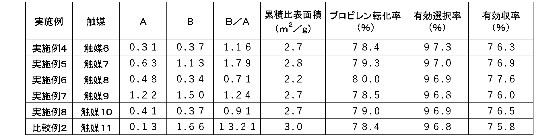

Claims (9)
- 水銀圧入法により測定した細孔分布(-dV/d(logD) vs D)において、細孔直径0.45~10.0μmの範囲および細孔直径0.040~0.45μmの範囲に各々少なくとも一つのピークを有し、かつ細孔直径0.45~10.0μmの範囲における-dV/d(logD)の最大値をAとし、細孔直径0.040~0.45μmの範囲における-dV/d(logD)の最大値をBとした場合に、(B/A)が0.20以上13.0以下である触媒(Vはサンプル重量あたりの圧入された水銀の容積(単位:mL/g)、Dは細孔直径(単位:μm)、logDはDの自然対数、-dV/d(logD)は特定の細孔直径範囲における累積細孔容積を細孔直径の対数で微分した値の反数を表す)。 In the pore distribution (-dV/d (log D) vs D) measured by the mercury intrusion method, at least -dV in the pore diameter range of 0.040 to 0.45 μm, with one peak and the maximum value of -dV / d (log D) in the pore diameter range of 0.45 to 10.0 μm. When the maximum value of /d (log D) is B, the catalyst (B/A) is 0.20 or more and 13.0 or less (V is the volume of mercury injected per sample weight (unit: mL/ g), D is the pore diameter (unit: μm), logD is the natural logarithm of D, -dV / d (logD) is the value obtained by differentiating the cumulative pore volume in a specific pore diameter range with the logarithm of the pore diameter ).
- 累積比表面積が5m2/g未満である請求項1に記載の触媒。 Catalyst according to claim 1, having a cumulative specific surface area of less than 5 m2 /g.
- モリブデン、ビスマスおよび鉄を含む、請求項1又は2に記載の触媒。 The catalyst according to claim 1 or 2, containing molybdenum, bismuth and iron.
- 下記式(1)で表される触媒組成を有する請求項3に記載の触媒。
Moa1Bib1Nic1Cod1Fee1Xf1Yg1Zh1Oi1・・・(1)
(式中、Mo、Bi、Ni、CoおよびFeはそれぞれモリブデン、ビスマス、ニッケル、コバルトおよび鉄を表し、Xはタングステン、アンチモン、錫、亜鉛、クロム、マンガン、マグネシウム、ケイ素、アルミニウム、セリウムおよびチタンから選ばれる少なくとも一種の元素、Yはナトリウム、カリウム、セシウム、ルビジウム、およびタリウムから選ばれる少なくとも一種の元素、Zは周期表の第1族から第16族に属し、上記Mo、Bi、Ni、Co、Fe、X、およびY以外の元素から選ばれる少なくとも一種の元素を意味するものであり、a1、b1、c1、d1、e1、f1、g1、h1、およびi1はそれぞれモリブデン、ビスマス、ニッケル、コバルト、鉄、X、Y、Zおよび酸素の原子数を表し、a1=12としたとき、0<b1≦7、0≦c1≦10、0<d1≦10、0<c1+d1≦20、0<e1≦5、0≦f1≦2、0≦g1≦3、0≦h1≦5を満たし、i1は各元素の酸化状態によって決まる値である。)
前駆体。 4. The catalyst according to claim 3, which has a catalyst composition represented by the following formula (1).
Mo a1 Bi b1 Ni c1 Co d1 Fe e1 X f1 Y g1 Z h1 O i1 (1)
(wherein Mo, Bi, Ni, Co and Fe represent molybdenum, bismuth, nickel, cobalt and iron, respectively; X represents tungsten, antimony, tin, zinc, chromium, manganese, magnesium, silicon, aluminum, cerium and titanium Y is at least one element selected from sodium, potassium, cesium, rubidium, and thallium; Z belongs to groups 1 to 16 of the periodic table; Mo, Bi, Ni, It means at least one element selected from elements other than Co, Fe, X, and Y, and a1, b1, c1, d1, e1, f1, g1, h1, and i1 are molybdenum, bismuth, and nickel, respectively. , cobalt, iron, X, Y, Z and oxygen. <e1 ≤ 5, 0 ≤ f1 ≤ 2, 0 ≤ g1 ≤ 3, 0 ≤ h1 ≤ 5, and i1 is a value determined by the oxidation state of each element.)
precursor. - 不活性担体に担持された請求項1から4のいずれか一項に記載の触媒。 The catalyst according to any one of claims 1 to 4 supported on an inert carrier.
- 前記不活性担体がシリカ及び/又はアルミナである請求項5に記載の触媒。 The catalyst according to claim 5, wherein the inert carrier is silica and/or alumina.
- 不飽和アルデヒド化合物、不飽和カルボン酸化合物、又は共役ジエン化合物製造用である請求項1から6のいずれか一項に記載の触媒。 The catalyst according to any one of claims 1 to 6, which is for producing an unsaturated aldehyde compound, an unsaturated carboxylic acid compound, or a conjugated diene compound.
- 請求項1から7のいずれか一項に記載の触媒を用いた不飽和アルデヒド化合物、不飽和カルボン酸化合物、又は共役ジエン化合物の製造方法。 A method for producing an unsaturated aldehyde compound, an unsaturated carboxylic acid compound, or a conjugated diene compound using the catalyst according to any one of claims 1 to 7.
- 前記不飽和アルデヒド化合物がアクロレインであり、前記不飽和カルボン酸化合物がアクリル酸であり、前記共役ジエン化合物がブタジエンである請求項8に記載の製造方法。 The production method according to claim 8, wherein the unsaturated aldehyde compound is acrolein, the unsaturated carboxylic acid compound is acrylic acid, and the conjugated diene compound is butadiene.
Priority Applications (3)
| Application Number | Priority Date | Filing Date | Title |
|---|---|---|---|
| JP2023531004A JP7383202B2 (en) | 2021-11-30 | 2022-11-29 | Catalyst and method for producing compounds using the same |
| KR1020247018177A KR20240116733A (en) | 2021-11-30 | 2022-11-29 | Catalyst and method for producing compounds using the same |
| CN202280079252.0A CN118338962A (en) | 2021-11-30 | 2022-11-29 | Catalyst and method for producing compound using the same |
Applications Claiming Priority (2)
| Application Number | Priority Date | Filing Date | Title |
|---|---|---|---|
| JP2021193719 | 2021-11-30 | ||
| JP2021-193719 | 2021-11-30 |
Publications (1)
| Publication Number | Publication Date |
|---|---|
| WO2023100856A1 true WO2023100856A1 (en) | 2023-06-08 |
Family
ID=86612186
Family Applications (1)
| Application Number | Title | Priority Date | Filing Date |
|---|---|---|---|
| PCT/JP2022/043923 WO2023100856A1 (en) | 2021-11-30 | 2022-11-29 | Catalyst, and method for producing compound using same |
Country Status (4)
| Country | Link |
|---|---|
| JP (1) | JP7383202B2 (en) |
| KR (1) | KR20240116733A (en) |
| CN (1) | CN118338962A (en) |
| WO (1) | WO2023100856A1 (en) |
Citations (9)
| Publication number | Priority date | Publication date | Assignee | Title |
|---|---|---|---|---|
| JP2007505740A (en) * | 2003-09-22 | 2007-03-15 | ビーエーエスエフ アクチェンゲゼルシャフト | Method for producing ring-shaped unsupported catalyst |
| JP2007511565A (en) * | 2003-11-18 | 2007-05-10 | ビーエーエスエフ アクチェンゲゼルシャフト | Method for producing acrolein by partial gas phase oxidation of propene by heterogeneous catalytic reaction |
| JP2008086877A (en) * | 2006-09-29 | 2008-04-17 | Nippon Shokubai Co Ltd | Catalyst for producing ethylene oxide and manufacturing method of ethylene oxide |
| JP2010029844A (en) * | 2008-07-04 | 2010-02-12 | Jgc Corp | Catalyst for catalytic partial oxidation of hydrocarbon and process for producing synthesis gas |
| JP5970542B2 (en) | 2012-04-23 | 2016-08-17 | 日本化薬株式会社 | Process for producing molded catalyst and process for producing diene or unsaturated aldehyde and / or unsaturated carboxylic acid using the molded catalyst |
| WO2016136882A1 (en) | 2015-02-27 | 2016-09-01 | 日本化薬株式会社 | Catalyst for manufacturing unsaturated aldehyde and/or unsaturated carboxylic acid and manufacturing method of same, and manufacturing method of unsaturated aldehyde and/or unsaturated carboxylic acid |
| JP2017024009A (en) | 2016-10-24 | 2017-02-02 | 旭化成株式会社 | Oxide catalyst |
| JP6447327B2 (en) | 2015-04-02 | 2019-01-09 | 三菱ケミカル株式会社 | Composite oxide catalyst, method for producing acrolein and acrylic acid using the same |
| JP2021193719A (en) | 2020-06-08 | 2021-12-23 | ソニーセミコンダクタソリューションズ株式会社 | Light receiving element and electronic device |
Family Cites Families (3)
| Publication number | Priority date | Publication date | Assignee | Title |
|---|---|---|---|---|
| JPS5970542U (en) | 1982-11-04 | 1984-05-14 | 永大産業株式会社 | cabinet |
| JPH0438986Y2 (en) | 1987-09-17 | 1992-09-11 | ||
| JP3186215B2 (en) | 1992-06-04 | 2001-07-11 | 松下電器産業株式会社 | Chisso reflow device |
-
2022
- 2022-11-29 WO PCT/JP2022/043923 patent/WO2023100856A1/en active Application Filing
- 2022-11-29 CN CN202280079252.0A patent/CN118338962A/en active Pending
- 2022-11-29 JP JP2023531004A patent/JP7383202B2/en active Active
- 2022-11-29 KR KR1020247018177A patent/KR20240116733A/en unknown
Patent Citations (9)
| Publication number | Priority date | Publication date | Assignee | Title |
|---|---|---|---|---|
| JP2007505740A (en) * | 2003-09-22 | 2007-03-15 | ビーエーエスエフ アクチェンゲゼルシャフト | Method for producing ring-shaped unsupported catalyst |
| JP2007511565A (en) * | 2003-11-18 | 2007-05-10 | ビーエーエスエフ アクチェンゲゼルシャフト | Method for producing acrolein by partial gas phase oxidation of propene by heterogeneous catalytic reaction |
| JP2008086877A (en) * | 2006-09-29 | 2008-04-17 | Nippon Shokubai Co Ltd | Catalyst for producing ethylene oxide and manufacturing method of ethylene oxide |
| JP2010029844A (en) * | 2008-07-04 | 2010-02-12 | Jgc Corp | Catalyst for catalytic partial oxidation of hydrocarbon and process for producing synthesis gas |
| JP5970542B2 (en) | 2012-04-23 | 2016-08-17 | 日本化薬株式会社 | Process for producing molded catalyst and process for producing diene or unsaturated aldehyde and / or unsaturated carboxylic acid using the molded catalyst |
| WO2016136882A1 (en) | 2015-02-27 | 2016-09-01 | 日本化薬株式会社 | Catalyst for manufacturing unsaturated aldehyde and/or unsaturated carboxylic acid and manufacturing method of same, and manufacturing method of unsaturated aldehyde and/or unsaturated carboxylic acid |
| JP6447327B2 (en) | 2015-04-02 | 2019-01-09 | 三菱ケミカル株式会社 | Composite oxide catalyst, method for producing acrolein and acrylic acid using the same |
| JP2017024009A (en) | 2016-10-24 | 2017-02-02 | 旭化成株式会社 | Oxide catalyst |
| JP2021193719A (en) | 2020-06-08 | 2021-12-23 | ソニーセミコンダクタソリューションズ株式会社 | Light receiving element and electronic device |
Also Published As
| Publication number | Publication date |
|---|---|
| CN118338962A (en) | 2024-07-12 |
| JPWO2023100856A1 (en) | 2023-06-08 |
| KR20240116733A (en) | 2024-07-30 |
| JP7383202B2 (en) | 2023-11-17 |
Similar Documents
| Publication | Publication Date | Title |
|---|---|---|
| JP6363464B2 (en) | Method for producing unsaturated carboxylic acid, and supported catalyst | |
| JP7418252B2 (en) | Catalyst precursor, catalyst using the same, and manufacturing method thereof | |
| WO2015008815A1 (en) | Method for producing unsaturated aldehyde and/or unsaturated carboxylic acid | |
| WO2014181839A1 (en) | Catalyst for manufacturing unsaturated aldehyde and/or unsaturated carboxylic acid, method for manufacturing same, and method for manufacturing unsaturated aldehyde and/or unsaturated carboxylic acid | |
| CN113905818B (en) | Catalyst, catalyst filling method, and method for producing compound using catalyst | |
| JP2020073581A (en) | Method of producing at least one of unsaturated aldehyde and unsaturated carboxylic acid, and catalyst for producing at least one of unsaturated aldehyde and unsaturated carboxylic acid | |
| CN113939364B (en) | Catalyst, method for producing compound using the catalyst, and compound | |
| WO2023100856A1 (en) | Catalyst, and method for producing compound using same | |
| JP7325688B1 (en) | Catalyst and method for producing compound using the same | |
| JP7170375B2 (en) | Catalyst and method for producing unsaturated aldehyde and unsaturated carboxylic acid using the same | |
| JP7105395B1 (en) | Catalyst precursor, catalyst using the same, method for producing compound, and method for producing catalyst | |
| JP7209901B1 (en) | Catalyst and method for producing compound by gas-phase oxidation reaction using the same | |
| WO2024135497A1 (en) | Catalyst, and compound production method using same | |
| WO2024135496A1 (en) | Catalyst and method for producing compound using same | |
| JP2023080395A (en) | Catalyst precursor, catalyst including the same, method for producing compound and method for producing catalyst | |
| JP2023112677A (en) | Catalyst, and method for producing compound by vapor-phase oxidation using the same | |
| JP2023081301A (en) | Catalyst, and method for producing compound using the same | |
| JP2022124634A (en) | Catalyst for production of isoprene and applications thereof | |
| JP2022082836A (en) | Catalyst production method | |
| JP2023141551A (en) | Catalyst and method for producing unsaturated aldehyde and/or unsaturated carboxylic acid using the same |
Legal Events
| Date | Code | Title | Description |
|---|---|---|---|
| WWE | Wipo information: entry into national phase |
Ref document number: 2023531004 Country of ref document: JP |
|
| 121 | Ep: the epo has been informed by wipo that ep was designated in this application |
Ref document number: 22901288 Country of ref document: EP Kind code of ref document: A1 |
|
| WWE | Wipo information: entry into national phase |
Ref document number: 202280079252.0 Country of ref document: CN |
|
| WWE | Wipo information: entry into national phase |
Ref document number: 18714756 Country of ref document: US |
|
| NENP | Non-entry into the national phase |
Ref country code: DE |
|
| ENP | Entry into the national phase |
Ref document number: 2022901288 Country of ref document: EP Effective date: 20240701 |