WO2023100561A1 - 測距装置、測距方法 - Google Patents
測距装置、測距方法 Download PDFInfo
- Publication number
- WO2023100561A1 WO2023100561A1 PCT/JP2022/040263 JP2022040263W WO2023100561A1 WO 2023100561 A1 WO2023100561 A1 WO 2023100561A1 JP 2022040263 W JP2022040263 W JP 2022040263W WO 2023100561 A1 WO2023100561 A1 WO 2023100561A1
- Authority
- WO
- WIPO (PCT)
- Prior art keywords
- signal
- circularly polarized
- mode
- unit
- radio waves
- Prior art date
- Legal status (The legal status is an assumption and is not a legal conclusion. Google has not performed a legal analysis and makes no representation as to the accuracy of the status listed.)
- Ceased
Links
Images













Classifications
-
- G—PHYSICS
- G01—MEASURING; TESTING
- G01S—RADIO DIRECTION-FINDING; RADIO NAVIGATION; DETERMINING DISTANCE OR VELOCITY BY USE OF RADIO WAVES; LOCATING OR PRESENCE-DETECTING BY USE OF THE REFLECTION OR RERADIATION OF RADIO WAVES; ANALOGOUS ARRANGEMENTS USING OTHER WAVES
- G01S7/00—Details of systems according to groups G01S13/00, G01S15/00, G01S17/00
- G01S7/02—Details of systems according to groups G01S13/00, G01S15/00, G01S17/00 of systems according to group G01S13/00
- G01S7/024—Details of systems according to groups G01S13/00, G01S15/00, G01S17/00 of systems according to group G01S13/00 using polarisation effects
- G01S7/026—Details of systems according to groups G01S13/00, G01S15/00, G01S17/00 of systems according to group G01S13/00 using polarisation effects involving the transmission of elliptically or circularly polarised waves
-
- G—PHYSICS
- G01—MEASURING; TESTING
- G01S—RADIO DIRECTION-FINDING; RADIO NAVIGATION; DETERMINING DISTANCE OR VELOCITY BY USE OF RADIO WAVES; LOCATING OR PRESENCE-DETECTING BY USE OF THE REFLECTION OR RERADIATION OF RADIO WAVES; ANALOGOUS ARRANGEMENTS USING OTHER WAVES
- G01S7/00—Details of systems according to groups G01S13/00, G01S15/00, G01S17/00
- G01S7/003—Transmission of data between radar, sonar or lidar systems and remote stations
- G01S7/006—Transmission of data between radar, sonar or lidar systems and remote stations using shared front-end circuitry, e.g. antennas
-
- G—PHYSICS
- G01—MEASURING; TESTING
- G01S—RADIO DIRECTION-FINDING; RADIO NAVIGATION; DETERMINING DISTANCE OR VELOCITY BY USE OF RADIO WAVES; LOCATING OR PRESENCE-DETECTING BY USE OF THE REFLECTION OR RERADIATION OF RADIO WAVES; ANALOGOUS ARRANGEMENTS USING OTHER WAVES
- G01S11/00—Systems for determining distance or velocity not using reflection or reradiation
- G01S11/02—Systems for determining distance or velocity not using reflection or reradiation using radio waves
-
- G—PHYSICS
- G01—MEASURING; TESTING
- G01S—RADIO DIRECTION-FINDING; RADIO NAVIGATION; DETERMINING DISTANCE OR VELOCITY BY USE OF RADIO WAVES; LOCATING OR PRESENCE-DETECTING BY USE OF THE REFLECTION OR RERADIATION OF RADIO WAVES; ANALOGOUS ARRANGEMENTS USING OTHER WAVES
- G01S13/00—Systems using the reflection or reradiation of radio waves, e.g. radar systems; Analogous systems using reflection or reradiation of waves whose nature or wavelength is irrelevant or unspecified
- G01S13/74—Systems using reradiation of radio waves, e.g. secondary radar systems; Analogous systems
- G01S13/82—Systems using reradiation of radio waves, e.g. secondary radar systems; Analogous systems wherein continuous-type signals are transmitted
- G01S13/84—Systems using reradiation of radio waves, e.g. secondary radar systems; Analogous systems wherein continuous-type signals are transmitted for distance determination by phase measurement
-
- G—PHYSICS
- G01—MEASURING; TESTING
- G01S—RADIO DIRECTION-FINDING; RADIO NAVIGATION; DETERMINING DISTANCE OR VELOCITY BY USE OF RADIO WAVES; LOCATING OR PRESENCE-DETECTING BY USE OF THE REFLECTION OR RERADIATION OF RADIO WAVES; ANALOGOUS ARRANGEMENTS USING OTHER WAVES
- G01S13/00—Systems using the reflection or reradiation of radio waves, e.g. radar systems; Analogous systems using reflection or reradiation of waves whose nature or wavelength is irrelevant or unspecified
- G01S13/87—Combinations of radar systems, e.g. primary radar and secondary radar
- G01S13/878—Combination of several spaced transmitters or receivers of known location for determining the position of a transponder or a reflector
-
- H—ELECTRICITY
- H01—ELECTRIC ELEMENTS
- H01Q—ANTENNAS, i.e. RADIO AERIALS
- H01Q13/00—Waveguide horns or mouths; Slot antennas; Leaky-waveguide antennas; Equivalent structures causing radiation along the transmission path of a guided wave
- H01Q13/08—Radiating ends of two-conductor microwave transmission lines, e.g. of coaxial lines, of microstrip lines
-
- H—ELECTRICITY
- H01—ELECTRIC ELEMENTS
- H01Q—ANTENNAS, i.e. RADIO AERIALS
- H01Q21/00—Antenna arrays or systems
- H01Q21/24—Combinations of antenna units polarised in different directions for transmitting or receiving circularly and elliptically polarised waves or waves linearly polarised in any direction
-
- H—ELECTRICITY
- H01—ELECTRIC ELEMENTS
- H01Q—ANTENNAS, i.e. RADIO AERIALS
- H01Q3/00—Arrangements for changing or varying the orientation or the shape of the directional pattern of the waves radiated from an antenna or antenna system
- H01Q3/24—Arrangements for changing or varying the orientation or the shape of the directional pattern of the waves radiated from an antenna or antenna system varying the orientation by switching energy from one active radiating element to another, e.g. for beam switching
-
- H—ELECTRICITY
- H01—ELECTRIC ELEMENTS
- H01Q—ANTENNAS, i.e. RADIO AERIALS
- H01Q9/00—Electrically-short antennas having dimensions not more than twice the operating wavelength and consisting of conductive active radiating elements
- H01Q9/04—Resonant antennas
- H01Q9/16—Resonant antennas with feed intermediate between the extremities of the antenna, e.g. centre-fed dipole
-
- H—ELECTRICITY
- H04—ELECTRIC COMMUNICATION TECHNIQUE
- H04B—TRANSMISSION
- H04B7/00—Radio transmission systems, i.e. using radiation field
- H04B7/02—Diversity systems; Multi-antenna system, i.e. transmission or reception using multiple antennas
- H04B7/10—Polarisation diversity; Directional diversity
Definitions
- This technology relates to ranging devices and mobile terminal devices, and more particularly to ranging devices and mobile terminal devices that perform ranging by transmitting and receiving circularly polarized radio waves.
- This technology aims to solve the above problems and aims to improve the accuracy of distance measurement.
- a ranging device performs, with other devices, first wireless communication using right-handed circularly polarized waves and second wireless communication using left-handed circularly polarized waves as communications for range finding by the phase-based method. and a first time waveform obtained by inverse Fourier transforming the frequency characteristic of the signal transmission path obtained based on the received signal by the first wireless communication and the received signal by the second wireless communication. and a distance measuring unit for measuring the distance to the other device based on a second time waveform obtained by inverse Fourier transforming the frequency characteristic of the signal transmission path obtained by the second time waveform.
- the first time waveform when receiving a circularly polarized radio wave that is easy for the antenna to receive among the right-handed circularly polarized wave and the left-handed circularly polarized wave, and the reception of the circularly polarized radio wave that is difficult for the antenna to receive A second temporal waveform of the time (or vice versa) can be used to identify direct wave components from other devices.
- the distance measurement method of the present technology includes a first wireless communication using right-handed circularly polarized waves and a second wireless communication using left-handed circularly polarized waves as communications for distance measurement using a phase-based method with another device. and a first time waveform obtained by performing an inverse Fourier transform on the frequency characteristic of a signal transmission path obtained based on the received signal by the first wireless communication and the received signal by the second wireless communication. and a second time waveform obtained by performing an inverse Fourier transform on the frequency characteristic of the signal transmission path obtained, and a process of measuring the distance to the other device.
- FIG. 4 is an example of a radio wave transmission/reception mode in an embodiment of the present technology, and is a diagram showing how a range finder receives a direct wave and a reflected wave reflected by a reflecting object.
- 1 is a block diagram of a computer device;
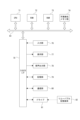
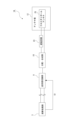
- FIG. 2 is a block diagram of each unit included in the range finder for transmitting and receiving radio waves;
- FIG. 3 is a functional block diagram of an arithmetic processing unit;
- FIG. FIG. 4 is a diagram showing an example of phase measurement in the phase-based method, and this diagram shows a case where radio waves are transmitted from the distance measuring device to the base station.
- FIG. 1 is a block diagram of a computer device
- FIG. 2 is a block diagram of each unit included in the range finder for transmitting and receiving radio waves
- FIG. 3 is a functional block diagram of an arithmetic processing unit
- FIG. 4 is a diagram showing an example of phase measurement in the phase-based method, and this diagram shows
- FIG. 4 is a diagram showing an example of phase measurement in a phase-based method, and this diagram shows a case where a rangefinder receives radio waves from a base station.
- FIG. 2 is an explanatory diagram of the phase of a signal propagation path measured in the phase-based method;
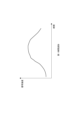
- FIG. 4 is a diagram illustrating phase characteristics with respect to frequency when the communication device is displaced; It is the figure which illustrated the inclination calculated from the phase characteristic.
- It is an explanatory diagram for explaining an example of a positioning method and this diagram is a diagram showing a state in which the positioning method is used in an ideal state.
- It is an explanatory diagram for explaining an example of a positioning method and this diagram is a diagram showing a state in which the positioning method is used in a state including an error.
- FIG. 1 is a block diagram showing an example of a configuration provided in a distance measuring device for reducing the influence of multipath; FIG. It is a figure for demonstrating a cross dipole antenna.
- FIG. 4 is a diagram showing an example of a first temporal waveform acquired when a first method is used as a direct wave component specifying method;
- FIG. 10 is a diagram showing an example of a second temporal waveform acquired when a first method is used as a direct wave component specifying method;
- FIG. 10 is a diagram showing changes in reception flags when the first method is used as a direct wave component specifying method;
- FIG. 10 is a diagram showing an example of a first temporal waveform acquired when a second method is used as a direct wave component specifying method;
- FIG. 4 is a diagram showing an example of a first temporal waveform acquired when a first method is used as a direct wave component specifying method
- FIG. 10 is a diagram showing an example of a second temporal waveform acquired when a
- FIG. 10 is a diagram showing an example of a second temporal waveform acquired when a second method is used as a direct wave component specifying method
- FIG. 10 is a diagram showing an example of a differential waveform acquired when a second method is used as a direct wave component specifying method
- 4 is a flow chart showing the flow of processing executed by the distance measuring device for distance measurement
- This figure is a block diagram showing an example of a configuration provided in a distance measuring device for reducing the influence of multipath.
- FIG. 1 is a block diagram showing an example of a configuration of a range finder having a hybrid coupler, which is an example of a configuration provided in a range finder for reducing the influence of multipath.
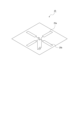
- FIG. 10 is a diagram showing an example using two sets of monopole antennas;
- FIG. 10 is a diagram showing an example using two sets of inverted-F antennas;
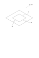
- FIG. 10 is a diagram showing an example using a plate-shaped inverted F antenna;
- FIG. 1 is a diagram showing an environment for accurately measuring position information of a ranging device 1 as a mobile terminal such as a smartphone owned by a user.
- the distance measuring device 1 measures the distance to the base station 2 by transmitting and receiving radio waves to and from the base station 2 whose position information is known. It is also possible to specify (estimate) the position information of itself by measuring distances to a plurality of base stations 2 .
- the base station 2 radiates right-hand circularly polarized wave (RHCP) radio waves, and the ranging device 1 receives the right-hand circularly polarized radio waves.
- RVCP right-hand circularly polarized wave
- the distance measuring device 1 since there is a reflector OB that is a perfect conductor around the distance measuring device 1 and the base station 2, the distance measuring device 1 receives only the direct wave DW in the radio waves transmitted from the base station 2. Instead of receiving the reflected wave RW reflected by the reflecting object OB.
- the distance measuring device 1 can receive only RHCP radio waves, it is not necessary to receive the reflected wave once.
- the direct wave component can be detected with high accuracy, the distance between the ranging device 1 and the base station 2 can be calculated with high accuracy, and highly accurate position information of the ranging device 1 can be obtained. It becomes possible.
- the distance measuring apparatus 1 receives not only the direct wave but also the one-time reflected wave, resulting in a decrease in distance measuring accuracy.
- the distance measuring device 1 has a configuration described later.
- the distance measuring device 1 is a computer device that performs various calculations. An example of the hardware configuration of the computer will be described with reference to FIG.
- a CPU (Central Processing Unit) 71 of the computer device functions as an arithmetic processing unit that performs various processes, and a nonvolatile memory such as a ROM (Read Only Memory) 72 and an EEP-ROM (Electrically Erasable Programmable Read-Only Memory).
- Various processes are executed according to programs stored in the unit 74 or programs loaded from the storage unit 79 to the RAM (Random Access Memory) 73 .
- the RAM 73 also appropriately stores data necessary for the CPU 71 to execute various processes.
- the CPU 71 may be implemented as a DSP (Digital Signal Processor) or the like.
- the CPU 71 performs signal processing, which will be described later, to perform processing for specifying a direct wave component, and also performs processing related to distance measurement.
- the CPU 71 , ROM 72 , RAM 73 and nonvolatile memory section 74 are interconnected via a bus 83 .
- An input/output interface (I/F) 75 is also connected to this bus 83 .
- the input/output interface 75 is connected to an input section 76 including operators and operating devices.
- an input section 76 including operators and operating devices.
- various operators and operating devices such as a keyboard, mouse, key, dial, touch panel, touch pad, remote controller, etc. are assumed.
- a user's operation is detected by the input unit 76 , and a signal corresponding to the input operation is interpreted by the CPU 71 .
- the input/output interface 75 is connected integrally or separately with a display unit 77 such as an LCD or an organic EL (Electronic Luminescent) panel, and an audio output unit 78 such as a speaker.
- the display unit 77 is a display unit that performs various displays, and is configured by, for example, a display device provided in the housing of the computer device, a separate display device connected to the computer device, or the like.
- the display unit 77 displays images for various image analysis processes, moving images to be processed, etc. on the display screen based on instructions from the CPU 71 . Further, the display unit 77 displays various operation menus, icons, messages, etc., ie, as a GUI (Graphical User Interface), based on instructions from the CPU 71 .
- GUI Graphic User Interface
- the input/output interface 75 may be connected to a storage unit 79 made up of a hard disk, solid-state memory, etc., and a communication unit 80 made up of a modem or the like.
- the communication unit 80 performs communication processing via a transmission line such as the Internet, and communication by wired/wireless communication with various devices, bus communication, and the like.
- a transmission line such as the Internet
- various devices such as the Internet
- wired/wireless communication with various devices, bus communication, and the like.
- the communication section 80 by providing an antenna section, various switches, etc., which will be described later as the communication section 80, transmission and reception of at least one of RHCP and LHCP radio waves is possible.
- a drive 81 is also connected to the input/output interface 75 as required, and a removable storage medium 82 such as a magnetic disk, optical disk, magneto-optical disk, or semiconductor memory is appropriately mounted.
- Data files such as programs used for each process can be read from the removable storage medium 82 by the drive 81 .
- the read data file is stored in the storage unit 79 , and the image and sound contained in the data file are output by the display unit 77 and the sound output unit 78 .
- Computer programs and the like read from the removable storage medium 82 are installed in the storage unit 79 as required.
- software for the processing of this embodiment can be installed via network communication by the communication unit 80 or via the removable storage medium 82 .
- the software may be stored in advance in the ROM 72, the storage unit 79, or the like.
- the information processing apparatus is not limited to being composed of a single computer device as shown in FIG. 2, and may be configured by systematizing a plurality of computer devices.
- the plurality of computer devices may be systematized by a LAN (Local Area Network) or the like, or may be remotely located by a VPN (Virtual Private Network) or the like using the Internet or the like.
- the plurality of computing devices may include computing devices as a group of servers (cloud) available through a cloud computing service.
- FIG. 3 shows a specific example of the configuration provided in the ranging device 1 or the base station 2 for transmitting and receiving circularly polarized radio waves for ranging.
- the distance measuring device 1 includes an arithmetic processing unit 3, a modulator 4, a DAC (Digital to Analog Converter) 5, a transmission unit 6, a frequency synthesizer 7, a transmission amplifier 8, and a transmission/reception switch. It has a section 9 , a splitter/combiner 10 , a polarization switching section 11 and an antenna section 12 .
- the distance measuring device 1 in this example is capable of performing wireless communication according to, for example, the BLE (Bluetooth Low Energy: Bluetooth is a registered trademark) system.
- BLE Bluetooth Low Energy: Bluetooth is a registered trademark
- With the BLE system it is possible to minimize the time required for operations that require a large amount of power, such as connection establishment and data communication. Therefore, power consumption can be suppressed, and the size of the distance measuring device 1 can be reduced.
- the arithmetic processing unit 3 supplies data to be transmitted to the modulator 4 .
- a modulator 4 modulates a signal for wireless communication with another device such as the base station 2 .
- modulation processing for example, IQ modulation is performed.
- I-channel (In-phase: in-phase component) and Q-channel (Quadrature: quadrature component) signals are used as baseband signals.
- the modulator 4 subjects the data to be transmitted supplied from the arithmetic processing unit 3 to modulation processing as IQ modulation.
- the DAC 5 converts the digital signal from the modulator 4 into an analog signal.
- An analog signal converted by the DAC 5 is supplied to the transmission section 6 .
- the transmission unit 6 is a block that transmits signals by communication using radio waves. As illustrated, the transmission unit 6 has a BPF (Band Pass Filter) 13 and a mixer 14 .
- the BPF 13 passes only signals in a specific frequency band. That is, the BPF 13 supplies the mixer 14 with only signals in a specific frequency band among the analog signals from the DAC 5 .
- the mixer 14 mixes the signal supplied from the BPF 13 with the local oscillation frequency supplied from the frequency synthesizer 7 to convert the signal into a transmission frequency for wireless communication.
- the frequency synthesizer 7 supplies frequencies used for transmission and reception. Specifically, the frequency synthesizer 7 has a local oscillator inside and is used for conversion between a radio frequency signal and a baseband signal for wireless communication.
- the transmission amplifier 8 amplifies the signal output from the transmission section 6 .
- the transmission/reception switching unit 9 is a switch for switching radio frequency (RF) signals.
- the transmission/reception switching unit 9 enables transmission of radio waves from the antenna unit 12 by connecting the transmission unit 6 to the splitter/combiner 10 when transmitting data, and connects the receiving unit 16 (to be described later) to the splitter/combiner 10 when receiving data. 10, the antenna section 12 can receive radio waves.
- RF radio frequency
- the distributor/combiner 10 distributes the signal output from the transmission/reception switching unit 9 to two systems during data transmission, and outputs the signal.
- Polarization switching section 11 applies a predetermined delay to one of the two-system signals output from splitter/combiner 10 . For example, a delay is applied so that the phase difference between the signals of the two systems is 90 degrees.
- Two electric wires feeder lines
- switching between RHCP and LHCP for radio waves is performed depending on which one of the two electric wires is supplied with the signal to which the delay is applied. conduct.
- the configurations of the distributor/combiner 10 and the polarization switching section 11 will be described in detail again.
- the antenna unit 12 is configured with one or more antennas for transmitting and receiving signals by wireless communication.
- the antenna section 12 in this embodiment is configured to have one antenna.
- the distance measuring device 1 includes an arithmetic processing unit 3, a transmission/reception switching unit 9, a distributor/synthesizer 10, a polarization switching unit 11, an antenna unit 12, and a reception amplifier 15. , a receiver 16, and an ADC (Analog to Digital Converter) 17.
- arithmetic processing unit 3 a transmission/reception switching unit 9, a distributor/synthesizer 10, a polarization switching unit 11, an antenna unit 12, and a reception amplifier 15.
- ADC Analog to Digital Converter
- the receiving unit 16 is a block that receives signals through radio wave communication.
- the receiver 16 has a mixer 18, a BPF 19, a VGA (Variable Gain Amplifier) 20, a BPF 21, and a VGA 22, as shown in FIG.
- the antenna unit 12 receives RHCP or LHCP radio waves and outputs them to the polarization switching unit 11 via two wires.
- the polarization switching section 11 applies a delay to one of the two systems of received signals output from the antenna section 12 and outputs it to the splitter/combiner 10 in the subsequent stage. At this time, the received signal of the RHCP radio wave is strengthened or the received signal of the LHCP radio wave is strengthened depending on which of the two systems of received signals the delay is applied to.
- the splitter/combiner 10 combines the two-system signals output from the polarization switching unit 11 into one-system signal, and outputs the signal to the reception amplifier 15 via the transmission/reception switching unit 9 .
- the reception amplifier 15 amplifies the signal output from the transmission/reception switching section 9 .
- the mixer 18 mixes the signal supplied from the receiving amplifier 15 with the local oscillation frequency supplied from the frequency synthesizer 7 to convert the signals into I-channel and Q-channel signals.
- An I-channel signal (denoted as “Ich” in the figure) is supplied to the BPF 19, and a Q-channel signal (denoted as "Qch” in the figure) is supplied to the BPF 21, respectively.
- the I-channel signal obtained by the mixer 18 is input to the BPF 19 to extract only the signal in a specific frequency band and supplied to the VGA 20 .
- the Q-channel signal obtained by the mixer 18 is input to the BPF 21 to extract only the signal in a specific frequency band and supplied to the VGA 22 .
- the VGA 20 and VGA 22 function as analog variable gain amplifiers that adjust the gains of the I-channel signal supplied from the BPF 19 and the Q-channel signal supplied from the BPF 21, respectively.
- the ADC 17 converts the I-channel and Q-channel signals from the receiver 16, that is, the I-channel and Q-channel signals output via the VGA 20 and VGA 22, from analog signals to digital signals.
- the I-channel and Q-channel signals converted into digital signals are supplied to the arithmetic processing unit 3 .
- the arithmetic processing unit 3 performs processing such as demodulating received data based on the data of the I-channel and Q-channel signals supplied from the ADC 17 . In addition, as described above, the arithmetic processing unit 3 supplies data to be transmitted to the modulator 4 and performs processing for modulation.
- the arithmetic processing unit 3 performs processing such as demodulating received data based on the data of the I-channel and Q-channel signals supplied from the ADC 17 . In addition, as described above, the arithmetic processing unit 3 supplies data to be transmitted to the modulator 4 and performs processing for modulation.
- the arithmetic processing unit 3 of the distance measuring device 1 in this example has a function as a communication processing unit F1 and a function as a switching unit F2 as functions for performing distance measurement using wireless communication. , a function as a frequency phase characteristic acquisition unit F3, and a function as a distance measurement unit F4.
- the communication processing unit F1 performs processing for supplying data to be transmitted to the modulator 4, processing for demodulating received data based on the data of each signal of the I channel and Q channel, and switching between transmission mode and reception mode for each unit. processing, etc.
- the switching unit F2 performs processing for switching between the first mode M1 in which communication is performed using RHCP radio waves and the second mode M2 in which communication is performed using LHCP radio waves.
- the frequency phase characteristic acquisition unit F3 acquires the phase characteristic with respect to the frequency of the signal propagation path with another communication device (for example, the base station 2).
- another communication device for example, the base station 2.
- processing is performed to acquire the phase characteristic with respect to the frequency of the signal propagation path. The distance measurement method using the phase-based method will be explained later.
- the distance measurement unit F4 calculates the distance to another communication device based on the phase characteristics for the frequency of the signal propagation path acquired by the frequency phase characteristics acquisition unit F3. A method of calculating the distance by the distance measuring unit F4 will also be described later.
- phase-based method> 5 and 6 are diagrams showing examples of phase measurement in the phase-based method.
- the phase-based method is a technology that can be implemented without using circularly polarized radio waves. In the following description, an example using radio waves of RHCP will be given.
- the phase is measured based on the results of communication using RHCP radio waves while changing the frequency between two devices (between the ranging device 1 and the base station 2 in FIG. 5).
- a measurement signal is transmitted from the distance measuring device 1 (initiator) to the base station 2 (reflector).
- the initiator here means a device that performs distance calculation processing based on the measured phase
- the reflector means a device paired with the initiator that exchanges measurement signals with the initiator.
- 5 and 6 mainly show the flow of measurement signals related to phase measurement. and the ADC 17 are omitted.
- a measurement signal is transmitted from the antenna included in the antenna section 12 from the arithmetic processing section 3 via the transmission section 6 .
- the measurement signal is received by the receiving section 16 via the antenna provided in the antenna section 12 .
- a measurement signal is returned from the base station 2 to the distance measuring device 1.
- the measurement signal is transmitted from the antenna of the antenna section 12 from the arithmetic processing section 3 via the transmission section 6, and in the rangefinder 1, the measurement signal is transmitted from the reception section 16 via the antenna of the antenna section 12. are received, and the phase characteristics between them are measured in the arithmetic processing unit 3 .
- round-trip communication it is possible to appropriately measure the phase characteristics between the two devices.
- FIG. 7 is an explanatory diagram of the phase ⁇ of the signal propagation path measured in the phase-based method.
- the base station 2 measures the signal phase ⁇ of the measurement signal.
- the signal phase ⁇ measured when the measurement signal is transmitted from the distance measuring device 1 (initiator) side to the base station 2 (reflector) side is denoted as " ⁇ IR" here.
- the distance measuring device 1 measures the signal phase ⁇ of the measurement signal.
- the signal phase ⁇ measured when the measurement signal is transmitted from the base station 2 side to the distance measuring device 1 side in this manner is denoted as " ⁇ RI".
- the signal phase ⁇ is obtained by the following [Equation 1] when the signals of the I channel and the Q channel obtained by receiving the measurement signal are set to "I” and "Q", respectively.
- the phase ⁇ of the signal propagation path is obtained based on the signal phase ⁇ IR and the signal phase ⁇ RI described above.
- the phase ⁇ is obtained by averaging the signal phase ⁇ IR and the signal phase ⁇ RI.
- the averaging operation here, in addition to the operation of obtaining the average value of the signal phases ⁇ IR and ⁇ RI, the addition operation of the signal phases ⁇ IR and ⁇ RI can also be performed.
- the phase ⁇ as described above is measured for each frequency while sequentially changing the frequency of the measurement signal within a predetermined frequency band.
- the phase ⁇ is measured for each of a plurality of frequencies.
- the "predetermined frequency band” here may be a frequency band defined as a usage band according to communication standards, such as the 2.4 GHz band (band from 2400 MHz to 2480 MHz) for BLE. .
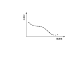
- the measurement results illustrated in FIG. 8 are obtained.
- the black circles in the figure represent the measurement results of the phase ⁇ at each frequency.
- the result shown in FIG. 8 can be rephrased as the phase characteristic with respect to the frequency of the signal propagation path.
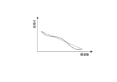
- the phase-based method distance measurement is performed based on the change in phase ⁇ when the frequency changes. Specifically, in the characteristics of the phase ⁇ with respect to frequency change, the magnitude of the gradient of the phase ⁇ as shown in FIG. 9 correlates with the magnitude of the distance. At this time, the steeper the slope of the phase ⁇ , the longer the distance. Therefore, the distance can be calculated based on the gradient of the phase ⁇ .
- the reason for using the group delay ⁇ is to eliminate the influence of the 2 ⁇ ambiguity of the phase.
- the group delay ⁇ is obtained by differentiating the phase ⁇ with respect to the angular frequency ⁇ .
- the method of calculating the distance based on the characteristics of the phase ⁇ with respect to frequency that is, the phase characteristics with respect to frequency of the signal propagation path is not limited to the above method, and various methods are conceivable.
- phase ⁇ with respect to frequency not only the characteristics of phase ⁇ with respect to frequency but also the characteristics of amplitude with respect to frequency are obtained.
- the characteristic is converted into a waveform obtained by inverse Fourier transform such as IFFT (Inverse Fast Fourier Transform) (a waveform with the horizontal axis as the time axis and the vertical axis as the signal intensity, hereinafter referred to as "time waveform"), and the time It is conceivable to adopt a method of obtaining the distance based on the waveform.
- IFFT Inverse Fast Fourier Transform
- the phase-based method Since the phase ⁇ changes according to the frequency, distance measurement by the phase-based method is possible in principle by measuring the phase ⁇ for at least two or more frequencies.
- the distance is calculated by obtaining the phase ⁇ from the measurement results of the signal phase ⁇ in both directions from the ranging device 1 to the base station 2 and from the base station 2 to the ranging device 1.
- this is a method for obtaining the distance based on the relative difference information of the signal phase ⁇ . Therefore, the phase-based method has the advantage that it is possible to prevent the accuracy of distance measurement from deteriorating due to the absolute value of the circuit delay of each block involved in signal transmission/reception and the variation due to the temperature characteristics.
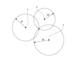
- the position of the distance measuring device 1 can be determined by triangulation. can be specified. Specifically, since the location of each base station 2 is known, the location of the distance measuring device 1 is determined by the distance from each base station 2 to each base station 2, as shown in FIG. It can be obtained as an intersection point (x mark in the figure) of three circles each having a radius of D (D1, D2 and D3 in the figure). However, in practice, it is rare for the three circles to intersect at one point. That is, even if the circles intersect, there are usually a plurality of points of intersection V present.
- FIG. 11 shows that the three circles do not intersect at one point, and the three circles produce a total of six points of intersection V1, P2, P3, P4, P5, and P6.
- the position of the device to be positioned (that is, the distance measuring device 1) can be calculated.
- the three points that connect the points to form a triangle that has the smallest area in other words, form an overlapping portion of three circles.
- a method of specifying three intersection points V (three points of intersection points V2, P4, and P5 in the example of the figure) and determining the barycentric position of the triangle formed by the three points as the position of the positioning target device can be cited.
- the positioning calculation method for specifying the position of the positioning target device using the distance D between the plurality of base stations 2 is limited to the positioning calculation method using the centroid method (centroid method) as described above. It is not limited to a specific method, but rather a variety of possible methods.
- the present embodiment has a configuration for reducing the influence of multipath, which is a problem when performing ranging or positioning as described above. Specifically, since the distance measuring device 1 includes the distributor/combiner 10 and the polarization switching unit 11, the direct wave component can be specified, so that the influence of multipath can be reduced.
- FIG. 12 omits the configuration of each unit provided between the arithmetic processing unit 3 and the transmission/reception switching unit 9 .
- the transmission/reception switching unit 9 is configured as, for example, an SPDT (Single-Pole/Double-Throw) switch, and switches between the transmission mode and the reception mode based on the transmission/reception switching signal S1 supplied from the arithmetic processing unit 3.
- SPDT Single-Pole/Double-Throw
- the transmission/reception switching unit 9 When switched to the transmission mode by the transmission/reception switching signal S1, the transmission/reception switching unit 9 outputs the signal from the transmission amplifier 8 to the splitter/combiner 10 in the subsequent stage.
- the distributor/combiner 10 distributes the signal output from the transmission/reception switching unit 9 to two systems and outputs the signal at the time of data transmission.
- the polarization switching section 11 includes a delay circuit 23 and a polarization switching switch 24 .
- the delay circuit 23 is provided to delay the phase of one of the two-system signals input from the distributor/combiner 10 by 90 degrees.
- the polarization switching switch 24 is configured as, for example, a DPDP (Double-Pole/Double-Throw) switch, and has four ports (first port P1, second port P2, third port P3, fourth port P4). I have.
- DPDP Double-Pole/Double-Throw
- the output signal from the divider/combiner 10 is input to the first port P1 through the delay circuit 23, and the output signal from the divider/combiner 10 is input to the second port P2. is entered. Also, the signal output from the third port P3 is input to the cross dipole antenna 25 of the antenna section 12 .
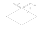
- the cross dipole antenna 25 has a structure in which two pairs of dipole antennas 25a and 25b are arranged orthogonally at 90 degrees.
- the radio waves radiated from the cross dipole antenna 25 can be circularly polarized.
- the feeding signal supplied to the dipole antenna 25a is set to +90 deg and -90 deg with respect to the feeding signal supplied to the dipole antenna 25b
- the circularly polarized waves of the radiated radio waves are RHCP and LHCP. can be switched.
- the method of feeding power to the cross dipole antenna 25 it is possible to switch between radiation of radio waves in the first mode M1 and radiation of radio waves in the second mode M2.
- the polarization changeover switch 24 is used as a switch for switching between RHCP and LHCP in this manner, and connects the signal input to the first port P1 to the third port P3 and the signal input to the second port P2 to the fourth port P2.
- a mode of connecting to the port P4 and a mode of connecting the signal input to the first port P1 to the fourth port P4 and the signal input to the second port P2 to the third port P3 are switched.
- the polarization switching switch 24 switches between the first port P1 and the second port P2, and the third port P3 and the fourth port P4. is switched between the first mode M1 for communication using RHCP radio waves and the second mode M2 for communication using LHCP radio waves.
- signals with a phase difference of 90 degrees from the dipole antennas 25 a and 25 b are input to the polarization switching switch 24 .
- the polarization switching signal S2 for switching to the first mode M1 for receiving RHCP radio waves from the arithmetic processing unit 3 is supplied to the polarization switching switch 24 .
- the signal output from the first port P1 through the delay circuit 23 and the signal output from the second port P2 are in phase. assumed.
- the splitter/combiner 10 synthesizes the two-system signals output from the polarization switching section 11 into one-system signal, and outputs the single-system signal to the transmission/reception switching section 9 . Therefore, both signals are combined in the distributor/combiner 10 and output to the subsequent transmission/reception switching section 9 as a received signal.
- the polarization switching signal S2 for switching to the second mode M2 for receiving LHCP radio waves from the arithmetic processing unit 3 is supplied to the polarization switching switch 24 .
- the signal output from the first port P1 through the delay circuit 23 and the signal output from the second port P2 are in phase. assumed. Therefore, both signals are combined in the distributor/combiner 10 and output to the subsequent transmission/reception switching section 9 as a received signal.
- the transmission/reception switching unit 9 outputs the signal from the splitter/combiner 10 to the reception amplifier 15 when switched to the reception mode by the transmission/reception switching signal S1.
- the splitter/combiner 10 when the ideal LHCP radio wave is received in the first mode M1 or when the ideal RHCP radio wave is received in the second mode M2, the splitter/combiner 10 It was described that the signal is not output from However, the radio waves received by the antenna unit 12 in a real environment are a mixture of various radio waves and noise. Therefore, even if the RHCP radio wave radiated from the base station 2 is received in the second mode M2, which does not correspond to it, the splitter/combiner 10 outputs some kind of signal. Similarly, even if the radio wave of LHCP emitted from the base station 2 is received in the first mode M1 that does not support it, some kind of signal is output from the splitter/combiner 10 .
- RHCP radio waves emitted from the base station 2 are received in the first mode M1, and LHCP radio waves are received in the second mode M2.
- the case is described as "receiving in supported mode”.
- the time waveform obtained by receiving in the compatible mode and the time waveform obtained by receiving in the non-compatible mode are used. .
- the time signal obtained by receiving the radio wave in the first mode M1 for receiving the radio wave of RHCP is defined as a first time waveform
- the time signal obtained by receiving the radio wave in the second mode M2 is defined as Let it be the second time waveform.
- the first time waveform is the time waveform based on reception in the compatible mode
- the second time waveform is the time waveform based on reception in the non-compatible mode. It is assumed that the time waveform is based on
- the first time waveform is the time waveform based on reception in the non-compliant mode
- the second time waveform is the time waveform based on reception in the compatible mode. It is assumed that the time waveform is based on
- a first method for identifying the direct wave component is a method using a noise determination threshold Th1.
- Th1 a noise determination threshold
- FIG. 14 shows a first temporal waveform, which is assumed to be a temporal waveform based on reception in the corresponding mode.
- FIG. 15 shows a second time waveform, which is a time waveform based on reception in the non-compliant mode.
- the noise determination threshold Th1 is a threshold for determining whether or not the received signal is noise. Specifically, when the noise determination threshold Th1 is not exceeded, it is determined that only noise is received, and when the noise determination threshold Th1 is exceeded, a signal other than noise, that is, a signal to be received is received. is determined to be
- the signal strength of the received signal exceeds the noise determination threshold Th1 at the timing of time T1. Therefore, it is determined that the signal received after time T1 contains the direct wave component.
- the period during which direct waves are received is referred to as a "direct wave reception period Tr". Also, in the first temporal waveform shown in FIG. 14, since the peak is positioned at time T2, it may be determined that the direct wave is received around time T2.
- the direct wave component is determined also using the second time waveform, which is the time waveform based on the reception in the non-supporting mode.
- the second time waveform shown in FIG. 15 the signal strength of the received signal exceeds the noise determination threshold Th1 at the timing of time T3.
- the result of determining the reception flag of the direct wave component (set to 1 when the direct wave is received and set to 0 otherwise), and the second time waveform of FIG. FIG. 16 shows the result of determining the reception flag of the direct wave component based on the above.
- the reception flag is set to "1" for both the first time waveform and the second time waveform around time T2. Therefore, it can be determined that the peak was formed during this period due to the reception of a large amount of noise components.
- the reception flag is set to "0" in the second time waveform, which is the time waveform based on the reception in the non-compliant mode, whereas the reception flag is set to "0" in the reception in the compatible mode.
- the reception flag is set to "1" in the first time waveform, which is the time waveform based on .
- the received signal that is likely to be buried in noise contains the direct wave component
- the period from time T1 to time T3 is the direct wave reception period Tr, or the direct wave reception period Tr is It can be determined that the period is included. That is, by using both the first time waveform and the second time waveform, erroneous determination of the direct wave reception period Tr based on the peak of the reception waveform can be avoided.
- a first method for specifying the direct wave component is a method using a difference waveform obtained by calculating the difference between the first time waveform and the second time waveform.
- a case where the base station 2 radiates RHCP radio waves will be described. This method is suitable in environments where the same level of noise is received in both the first mode M1 and the second mode M2.
- FIG. 17 shows a first temporal waveform, which is assumed to be a temporal waveform based on reception in the corresponding mode. Also, FIG. 18 shows a second time waveform, which is a time waveform based on reception in the non-compliant mode.
- the horizontal axis is time and the vertical axis is the signal strength of the received signal.
- a dull waveform is observed in the first temporal waveform shown in FIG. 17, and it is difficult to accurately specify the direct wave reception period Tr.
- the noise component is canceled and the direct wave component can be specified with high accuracy.
- the detection threshold Th2 may be used for determination (see FIG. 19).
- the horizontal axis in each of FIGS. 14 to 19 is the time axis, which can be rephrased as the axis representing the distance to the base station 2.
- FIG. Specifically, the distance to the base station 2 can be calculated by multiplying the time when the direct wave component is detected and the speed of light.
- Positioning can be measured by measuring distances to a plurality of base stations 2 using the method.
- step S101 the arithmetic processing unit 3 sets the first mode M1 to receive RHCP radio waves.
- the arithmetic processing unit 3 performs transmission/reception processing in step S102.
- the rangefinder 1 receives RHCP radio waves transmitted from the base station 2
- the base station 2 receives radio waves transmitted from the rangefinder 1 .
- This processing is performed to obtain the phase ⁇ for each frequency within a predetermined frequency band. This makes it possible to obtain the phase characteristic with respect to the frequency of the signal propagation path.
- step S103 the arithmetic processing unit 3 obtains the first time waveforms as shown in FIGS. 14 and 17 from the phase characteristics.
- step S104 the arithmetic processing unit 3 sets the second mode M2 in order to receive radio waves of LHCP.
- the arithmetic processing unit 3 performs transmission/reception processing in step S105.
- the transmission/reception processing is performed between the base station 2 and the distance measuring device 1 as in step S102.
- the arithmetic processing unit 3 obtains a second time waveform as shown in FIGS. 15 and 18 from the phase characteristics.
- step S107 the arithmetic processing unit 3 detects direct wave components using the first time waveform and the second time waveform. Specifically, as described above, a reception flag may be used, or a differential waveform may be calculated and used.
- step S108 the arithmetic processing unit 3 calculates the distance based on the detection result of the direct wave component.
- the radio wave transmitted from the base station 2 as either RHCP or LHCP is received by the distance measuring device 1 while switching between the first mode M1 and the second mode M2.
- the base station 2 is capable of transmitting only RHCP radio waves, and the ranging device 1 receives RHCP radio waves in the first mode M1 and also in the second mode M2. do.
- both the RHCP radio waves and the LHCP radio waves can be transmitted from the base station 2, and the distance measuring device 1A can receive only one of the RHCP radio waves and the LHCP radio waves. It is said that That is, the distance measuring device 1A can adopt only one of the first mode M1 and the second mode M2.
- FIG. 21 shows a configuration example of the distance measuring device 1A. 21, like FIG. 12, the configuration of each unit provided between the arithmetic processing unit 3 and the transmission/reception switching unit 9 is omitted.
- the range finder 1A does not include the polarization switching unit 11, it is possible to transmit and receive using only one of the RHCP radio waves and the LHCP radio waves.
- the distance measuring device 1A By switching radio waves transmitted by the base station 2 side between RHCP and LHCP, the distance measuring device 1A acquires a first time waveform based on reception in the compatible mode and a second time waveform based on reception in the non-compatible mode. It is possible to
- the same effect as in this modified example can be achieved by fixing to one of the modes. can do.
- the distance measuring device 1 described above is provided with the splitter/combiner 10 and the polarization switching unit 11 to enable transmission/reception of RHCP radio waves and transmission/reception of LHCP radio waves.
- a distance measuring device 1B in the second modification includes a polarization switching switch 24B and a hybrid coupler 26 instead of the splitter/combiner 10 and the polarization switching section 11. FIG.
- Fig. 22 shows a configuration example of the distance measuring device 1B. 22, like FIGS. 12 and 21, the configuration of each unit provided between the arithmetic processing unit 3 and the transmission/reception switching unit 9 is omitted.
- the distance measuring device 1B has a polarization switching switch 24B and a hybrid coupler 26.
- the polarization switching switch 24B is configured as an SPDT switch or the like, and functions as the polarization switching section 11 in FIG.
- the hybrid coupler 26 has four ports: a first port Po1, a second port Po2, a third port Po3, and a fourth port Po4.
- the two ports on the double-throw side of the polarization switching switch 24B are connected to the first port Po1 and the second port Po2, respectively.
- the hybrid coupler 26 can adjust the phase difference between the signal output from the third port Po3 and the signal output from the fourth port Po4 to 90 degrees.
- the hybrid coupler 26 When a signal is input to the first port Po1 and when a signal is input to the second port Po2, the hybrid coupler 26 outputs a signal output from the third port Po3 to the fourth port Po4. It is possible to switch between the case where the signal output from is advanced by 90 degrees and the case where it is delayed by 90 degrees.
- the polarization switching switch 24B switches between outputting the signal to the first port Po1 and the second port Po2 based on the polarization switching signal S2 supplied from the arithmetic processing unit 3. , the phase difference between the two signals output from the hybrid coupler 26 can be switched between 90 degrees and -90 degrees.
- the radio waves output from the cross dipole antenna 25 can be switched between RHCP and LHCP.
- the phase difference between the two output signals switches between 90 deg and -90 deg depending on whether the cross dipole antenna 25 receives RHCP radio waves or LHCP radio waves.
- the hybrid coupler 26 outputs a signal from the first port Po1 when the signal input to the third port Po3 is delayed by 90 degrees from the signal input to the fourth port Po4. At this time, no signal is output from the second port Po2.
- the hybrid coupler 26 outputs a signal from the second port Po2 when the signal input to the third port Po3 leads the signal input to the fourth port Po4 by 90 degrees. At this time, no signal is output from the first port Po1.
- the processing unit 3 switches the polarization switching signal S2 so that the polarization switching switch 24B receives only the output signal from the first port Po1, thereby receiving only one of the radio waves of RHCP and LHCP. possible configuration. Further, the arithmetic processing unit 3 can receive only the other circularly polarized radio wave by switching the polarization switching switch 24B to receive only the output signal from the second port Po2 by the polarization switching signal S2. can be configured.
- the arithmetic processing unit 3 can switch between the first mode M1 and the second mode M2 by the polarization switching signal S2.
- the antenna section 12 has only one antenna (cross dipole antenna 25). , 25L.
- Fig. 23 shows the configuration of the distance measuring device 1C. 23, like FIGS. 12, 21 and 22, the configuration of each unit provided between the arithmetic processing unit 3 and the transmission/reception switching unit 9 is omitted.
- the configuration of the distance measuring device 1C includes a configuration for RHCP and a configuration for LHCP for each of the transmission/reception switching unit 9, splitter/combiner 10, delay circuit 23, and cross dipole antenna 25.
- the ranging device 1C includes a transmission/reception switching unit 9R, a splitter/combiner 10R, a delay circuit 23R, and a cross dipole antenna 25R.
- the ranging device 1C includes a transmission/reception switching unit 9L, a splitter/combiner 10L, a delay circuit 23L, and a cross dipole antenna 25L.
- Arithmetic processing unit 3 switches transmission mode and reception mode in communication using cross dipole antenna 25R by supplying transmission/reception switching signal S1R to transmission/reception switching unit 9R. Further, the arithmetic processing unit 3 switches the transmission mode and the reception mode in communication using the cross dipole antenna 25L by supplying a transmission/reception switching signal S1L to the transmission/reception switching unit 9L.
- the configuration of the distance measuring device 1C is such that, for example, when the base station 2 transmits radio waves of RHCP, reception is performed in a corresponding mode using each unit corresponding to transmission and reception of radio waves of RHCP, and at the same time, reception of LHCP radio waves is performed. It is possible to perform reception in a non-compatible mode using each unit that supports wireless radio wave transmission/reception.
- the first time waveform and second time waveform can be acquired substantially at the same time, even in an environment where noise in the signal propagation path changes over time, the first time waveform and the second time waveform can be obtained.
- the influence of noise variations on waveforms can be minimized. That is, according to the configuration of the distance measuring device 1C, it is possible to improve the accuracy of distance measurement.
- the transmission/reception switching unit 9, the splitter/combiner 10, and the delay circuit 23 are configured to have one for RHCP and one for LHCP, respectively. It may be configured to be shared for RHCP and LHCP.
- the antenna section 12 (12C) in each example described above has the cross dipole antenna 25 (25R, 25L).
- the configuration of the antenna for transmitting and receiving radio waves of RHCP and LHCP is not limited to the cross dipole antenna.
- a patch antenna 27 may be used.
- the antenna section 12 includes a patch antenna 27 formed in a substantially rectangular shape, and a first wire 28 and a second wire connected to respective electrodes provided on two adjacent sides of the patch antenna 27 . 29.
- radio waves of RHCP or LHCP can be emitted.
- the phase of the signal supplied to the first wire 28 with respect to the signal supplied to the second wire 29 between +90 deg and -90 deg, communication by radio waves of RHCP and radio of LHCP It becomes possible to switch communication using radio waves.
- signals having a phase difference of 90 degrees are output from the first electric wire 28 and the second electric wire 29 to the subsequent stage.
- the delay circuit 23 (23R, 23L) is provided so that the phase difference is 90 degrees, but it is not necessary to delay one of the signals so that the phase difference is exactly 90 degrees. .
- the phase difference may be delayed between 30 degrees and 150 degrees, or may be delayed between 210 degrees and 330 degrees. Further, when switching from the mode of emitting radio waves of RHCP to the mode of emitting radio waves of LHCP at the time of transmission, the phase difference between the two signals supplied to the antenna unit 12 (12C) is between 30 degrees and 150 degrees. It can be realized by changing from the state in which the phase difference is in the range of 210 degrees to 330 degrees.
- the ranging device 1 (1A, 1B, 1C) communicates with another device (for example, the base station 2) for ranging by the phase-based method.
- a communication processing unit F1 that performs first wireless communication (transmission and reception based on RHCP) using circularly polarized waves and second wireless communication (transmitting and receiving based on LHCP) using left-hand circularly polarized waves, and based on the received signal by the first wireless communication
- the first time waveform see FIGS.
- the first time waveform when receiving a circularly polarized radio wave that is easy for the antenna to receive among the right-handed circularly polarized wave and the left-handed circularly polarized wave, and the reception of the circularly polarized radio wave that is difficult for the antenna to receive A second temporal waveform of the time (or vice versa) can be used to identify direct wave components from other devices. This makes it possible to calculate the distance to other devices with high accuracy. In addition, since the component of the primary reflected wave can be excluded, it is possible to further improve the distance measurement accuracy.
- the communication may be communication for receiving radio waves of polarized wave (LHCP).
- LHCP polarized wave
- a first time waveform and a second time waveform can be obtained.
- the distance measuring device 1A may include a signal receiving section (for example, the antenna section 12, the polarization switching section 11, the splitter/combiner 10) corresponding to either one of the radio waves. More specifically, the distance measuring device 1A includes an antenna section 12 that outputs a received signal having a phase difference based on reception of radio waves, and a combining section (delay circuit) that combines the received signals output from the antenna section 12. 23 and a distributor/combiner 10), and the combining unit is adapted to receive either right-handed circularly polarized (RHCP) radio waves or left-handed circularly polarized (LHCP) radio waves.
- RHCP right-handed circularly polarized
- LHCP left-handed circularly polarized
- the antenna unit 12 receives at least one of the circular radio waves as a direct wave component.
- the direction of rotation of the polarized wave and the direction of rotation of the circularly polarized wave corresponding to the antenna unit 12 are opposite to each other. Therefore, one of the first time waveform and the second time waveform does not contain many direct wave components but contains many noise components, making it possible to specify the noise components.
- the antenna unit 12 that outputs a received signal when receiving radio waves of the range finder 1 (1B, 1C) and the received signal output from the antenna unit 12 are synthesized.
- a combining unit (dividing/combining device 10 and delay circuit 23), a first mode M1 in which the combining unit performs combining corresponding to reception of a right-handed circularly polarized wave (RHCP) radio signal, and a combining unit in which left-handed circularly polarized wave a switching unit F2 for switching between a second mode M2 for performing synthesis corresponding to reception of radio wave signals of (LHCP), and the first radio communication is performed in a state where the radio wave is switched to the first mode M1.
- RHCP right-handed circularly polarized wave
- LHCP radio wave signals
- the second wireless communication may be wireless radio wave communication performed in the state switched to the second mode M2. That is, the switching unit F2 switches the polarization switching unit 11 or the polarization switching switch 24B to the first mode M1 so that the synthesizing unit performs synthesis corresponding to the reception of right-hand circularly polarized radio waves, and switches the polarization.
- the combining section performs combining corresponding to the reception of left-hand circularly polarized radio waves.
- either the right-handed circularly polarized radio wave or the left-handed circularly polarized radio wave transmitted from another device (base station 2) is received in the first mode M1 or received in the second mode M2. It is possible to receive by
- the combiner switches to the first mode M1.
- the synthesis unit receives Communication may be performed by receiving a radio wave of a specific circular polarization in a state of being switched to the 2-mode M2.
- the radio waves received from another device are received in both a mode (compatible mode) in which the rotational direction of the circularly polarized wave matches and a mode in which the direction of rotation does not match (non-compatible mode).
- base station 2 a mode (compatible mode) in which the rotational direction of the circularly polarized wave matches and a mode in which the direction of rotation does not match.
- a first time waveform and a second time waveform are obtained. Therefore, since direct waves from other devices can be specified, it is possible to perform highly accurate distance measurement.
- the antenna unit 12 (12C) included in the range finder 1 (1A, 1B, 1C) includes the cross dipole antennas 25 (25R, 25L) or patch antennas. It may be any of the antennas 27 .
- the cross dipole antenna 25 and the patch antenna 27 can be used to perform highly accurate distance measurement.
- the distance measuring device 1 may have a structure using two sets of monopole antennas instead of the cross dipole antenna 25 . Specifically, as shown in FIG. 25, it is composed of a ground plate 30 and two sets of monopole antennas 31a and 31b, and the phase difference between the monopole antennas 31a and 31b is 90 degrees. Apply a power supply signal.
- the range finder 1 may have a structure using two sets of inverted F antennas instead of the cross dipole antenna 25 .
- FIG. 26 it is composed of a ground plate 30 and two sets of inverted F antennas 32a and 32b, and the phase difference between the inverted F antennas 32a and 32b is 90 degrees. Apply a power supply signal.
- the distance measuring device 1 may be configured with a plate-shaped inverted F antenna instead of the patch antenna 27 .
- a ground plate 30 and a plate-like inverted F antenna 32 are provided, and a phase difference between a first electric wire 34a and a second electric wire 34b for supplying signals to the plate-like inverted F antenna 32 is provided. is 90 degrees.
- the switching unit F2 switches between the radio wave radiation in the first mode M1 and the radio wave radiation in the second mode M2 by switching the feeding method for the antenna unit 12 (12C). Switching may be performed.
- the antenna section 12 is composed of two pairs of dipole antennas 25a and 25b
- the phase difference between the feeding signals applied to the first dipole antenna 25a and the second dipole antenna 25b is set to 90 degrees.
- the radiation of radio waves in the first mode M1 and the radiation of radio waves in the second mode M2 can be switched.
- RHCP right-hand circularly polarized
- LHCP left-hand circularly polarized
- the switching unit F2 changes the phase difference between the two feed signals supplied to the antenna unit 12 (12C) from 30 degrees to 150 degrees to 210 degrees to 330 degrees.
- the mode may be switched by switching to the state in which the mode is switched. This makes it possible to switch radio communication from right-handed circularly polarized (RHCP) to left-handed circularly polarized (LHCP) or vice versa.
- RHCP right-handed circularly polarized
- LHCP left-handed circularly polarized
- the range finder 1B includes a switch element (polarization changeover switch 24B) and a signal input from the switch element to distribute signals to the antenna section 12 ( 12C) and output from the antenna unit 12, and a hybrid coupler 26 that combines the received signals and outputs them to the switching element, and the switching unit F2 outputs a switching signal to the switching element to switch the mode.
- a switch element polarization changeover switch 24B
- the switching unit F2 outputs a switching signal to the switching element to switch the mode.
- the antenna unit 12C includes a first antenna (cross dipole antenna 25R) capable of transmitting and receiving radio waves in the first mode M1, and a second A second antenna (cross dipole antenna 25L) capable of transmitting and receiving radio waves in mode M2 may be provided.
- a first antenna cross dipole antenna 25R
- a second A second antenna cross dipole antenna 25L
- an antenna suitable for receiving a direct wave component is provided. It can be specified, and highly accurate distance measurement can be performed.
- the distance measurement unit F4 sets the noise determination threshold Th1 in the first time waveform and the second time waveform.
- a time interval for which the determination result of whether or not it has exceeded is different may be determined as the direct wave reception period Tr, and distance measurement may be performed. This prevents the reflected wave component from being erroneously detected as the direct wave component, enabling appropriate distance measurement.
- the distance measuring unit F4 measures based on the difference between the first time waveform and the second time waveform. You can go distance.
- the direct wave component can be specified, so that the time period during which the direct wave component was mainly received can be specified, and appropriate distance measurement can be performed.
- the functions of the various distance measuring devices described above can be suitably implemented in portable terminal devices such as smartphones and tablet terminals.
- a mobile terminal device if the location information of the terminal itself can be specified with high accuracy, the usability of various applications can be improved. For example, in presenting advertisements using location information, it is possible to transmit appropriate advertisement information based on highly accurate location information and avoid transmitting inappropriate advertisement information. improvement and effective use of the communication band can be achieved.
- applications that perform navigation it is possible to reduce the presentation of incorrect guidance and prevent the user from making unnecessary movements, and in addition, it is possible to provide a user-friendly navigation function.
- a fair game environment can be provided by using highly accurate position information.
- This technology> (1) a communication processing unit that performs first wireless communication using right-handed circularly polarized waves and second wireless communication using left-handed circularly polarized waves as communications for distance measurement by a phase-based method with other devices; A first time waveform obtained by inverse Fourier transforming frequency characteristics of a signal transmission path obtained based on the received signal by the first wireless communication and a frequency of the signal transmission path obtained based on the received signal by the second wireless communication a distance measuring unit that measures the distance to the other device based on a second time waveform obtained by inverse Fourier transforming the characteristic.
- the first wireless communication is communication for receiving right-handed circularly polarized radio waves
- the range finder according to (1) wherein the second wireless communication is communication for receiving left-handed circularly polarized radio waves.
- the signal receiving unit has a synthesizing unit for synthesizing the two types of received signals,
- the distance measuring device according to (3), wherein the synthesizing unit performs synthesizing corresponding to either right-handed circularly polarized radio waves or left-handed circularly polarized radio waves.
- an antenna unit that outputs a received signal based on the reception of radio waves; a synthesizing unit that synthesizes the received signals output from the antenna unit; Switching between a first mode in which the synthesizing unit performs synthesizing corresponding to reception of a right-handed circularly polarized radio wave signal and a second mode in which the synthesizing unit performs synthesis corresponding to reception of a left-handed circularly polarized radio wave signal.
- the first wireless communication is radio wave communication performed in a state of being switched to the first mode
- the first radio communication is communication for receiving a radio wave of a specific circularly polarized wave, which is either a right-handed circularly polarized wave or a left-handed circularly polarized wave, in a state in which the synthesizing unit is switched to the first mode.
- the switching unit switches between radio wave radiation in the first mode and radio wave radiation in the second mode by switching a method of feeding power to the antenna unit.
- the distance measuring device according to .
- the switching unit performs mode switching by switching from a state in which the phase difference between two types of feed signals supplied to the antenna unit is 30 degrees or more and 150 degrees or less to a state in which the phase difference is 210 degrees or more and 330 degrees or less.
- the distance measuring device according to (8) above.
- the distance measuring device (10) a switch element; a hybrid coupler that distributes a signal input from the switch element, supplies it to the antenna unit, combines received signals output from the antenna unit, and outputs the combined signal to the switch element;
- the distance measuring device (10) wherein the switching unit performs mode switching by outputting a switching signal to the switching element.
- the antenna unit has a first antenna capable of transmitting/receiving radio waves in the first mode, and a second antenna capable of transmitting/receiving radio waves in the second mode.
- a distance measuring device according to any one of (6).
- the distance measuring unit determines a time interval in which the first time waveform and the second time waveform have different determination results as to whether or not the threshold value is exceeded as a direct wave reception period, and performs the distance measurement.
- the distance measuring device according to any one of (11) above.
- (13) The distance measuring device according to any one of (1) to (12) above, wherein the distance measurement unit performs the distance measurement based on a difference between the first time waveform and the second time waveform.
Landscapes
- Engineering & Computer Science (AREA)
- Radar, Positioning & Navigation (AREA)
- Remote Sensing (AREA)
- Computer Networks & Wireless Communication (AREA)
- Physics & Mathematics (AREA)
- General Physics & Mathematics (AREA)
- Signal Processing (AREA)
- Radar Systems Or Details Thereof (AREA)
- Variable-Direction Aerials And Aerial Arrays (AREA)
- Waveguide Aerials (AREA)
Abstract
本発明の測距装置(1)は、他の装置(2)との間で、位相ベース方式による測距のための通信として、右旋円偏波(RHCP)による第1無線通信と、左旋円偏波(LHCP)による第2無線通信とを行う通信処理部(F1)と、前記第1無線通信による受信信号に基づいて得られる信号伝送路の周波数特性を逆フーリエ変換して得られる第1時間波形と前記第2無線通信による受信信号に基づいて得られる信号伝送路の周波数特性を逆フーリエ変換して得られる第2時間波形とに基づいて、前記他の装置(2)との距離を測定する測距部(F4)と、を備える。 本発明によると、マルチパスによる測距精度の低下が改善される。
Description
本技術は測距装置、携帯端末装置に関し、特に円偏波の無線電波を送受信することにより測距を行う測距装置及び携帯端末装置についての技術に関する。
機器間の距離を適切に測定するためには測距精度が重要である。
下記特許文献1においては、指向性を切り換えることによって測距精度を改善する技術が開示されている。
下記特許文献1においては、指向性を切り換えることによって測距精度を改善する技術が開示されている。
しかし、ある機器から他の機器に対して無線電波を送信した際に、他の機器において直接波を受信した時刻と反射波を受信した時刻が近い場合については、指向性の切り換えを行うだけでは十分に直接波を抽出することができない虞がある。
本技術は、上記問題点の解決を図るものであり、測距精度の向上を図ることを目的とする。
本技術に係る測距装置は、他の装置との間で、位相ベース方式による測距のための通信として、右旋円偏波による第1無線通信と、左旋円偏波による第2無線通信とを行う通信処理部と、前記第1無線通信による受信信号に基づいて得られる信号伝送路の周波数特性を逆フーリエ変換して得られる第1時間波形と前記第2無線通信による受信信号に基づいて得られる信号伝送路の周波数特性を逆フーリエ変換して得られる第2時間波形とに基づいて、前記他の装置との距離を測定する測距部と、を備えたものである。
例えば、右旋円偏波と左旋円偏波のうちアンテナが受信しやすい円偏波の無線電波を受信したときの第1時間波形と、アンテナが受信しにくい円偏波の無線電波を受信したときの第2時間波形を用いて(或いはその逆でもよい)、他の装置からの直接波成分を特定することができる。
例えば、右旋円偏波と左旋円偏波のうちアンテナが受信しやすい円偏波の無線電波を受信したときの第1時間波形と、アンテナが受信しにくい円偏波の無線電波を受信したときの第2時間波形を用いて(或いはその逆でもよい)、他の装置からの直接波成分を特定することができる。
本技術の測距方法は、他の装置との間で、位相ベース方式による測距のための通信として、右旋円偏波による第1無線通信と、左旋円偏波による第2無線通信とを行う通信処理と、前記第1無線通信による受信信号に基づいて得られる信号伝送路の周波数特性を逆フーリエ変換して得られる第1時間波形と前記第2無線通信による受信信号に基づいて得られる信号伝送路の周波数特性を逆フーリエ変換して得られる第2時間波形とに基づいて、前記他の装置との距離を測定する処理と、を演算処理装置が実行する、ものである。
以下、実施の形態を次の順序で説明する。
<1.円偏波を利用した通信態様>
<2.測距装置の構成>
<3.位相ベース方式による測距及び測位>
<4.直接波成分の特定方法>
<4-1.第1の方法>
<4-2.第2の方法>
<4-3.測距方法>
<5.処理フロー>
<6.変形例>
<6-1.第1の変形例>
<6-2.第2の変形例>
<6-3.第3の変形例>
<6-4.第4の変形例>
<6-5.その他>
<7.まとめ>
<8.本技術>
<1.円偏波を利用した通信態様>
<2.測距装置の構成>
<3.位相ベース方式による測距及び測位>
<4.直接波成分の特定方法>
<4-1.第1の方法>
<4-2.第2の方法>
<4-3.測距方法>
<5.処理フロー>
<6.変形例>
<6-1.第1の変形例>
<6-2.第2の変形例>
<6-3.第3の変形例>
<6-4.第4の変形例>
<6-5.その他>
<7.まとめ>
<8.本技術>
<1.円偏波を利用した通信態様>
マルチパスによる測距精度の低下を改善するために、本実施の形態においては、円偏波の無線電波を用いた通信を行う。
先ず、理想環境における円偏波を用いた送受信について図1を参照して説明する。
図1は、ユーザが所持するスマートフォンなどの携帯端末としての測距装置1の位置情報を精度良く測定するための環境について示した図である。
マルチパスによる測距精度の低下を改善するために、本実施の形態においては、円偏波の無線電波を用いた通信を行う。
先ず、理想環境における円偏波を用いた送受信について図1を参照して説明する。
図1は、ユーザが所持するスマートフォンなどの携帯端末としての測距装置1の位置情報を精度良く測定するための環境について示した図である。
測距装置1は、位置情報が既知とされた基地局2に対して無線電波の送受信を行うことにより、基地局2までの距離を測定する。また、複数の基地局2に対して距離を測定することにより自身の位置情報を特定(推定)することも可能である。
基地局2は右旋円偏波(RHCP:Right Hand Circularly Polarized Wave)の無線電波を放射し、測距装置1は該右旋円偏波の無線電波を受信する。
ここで、測距装置1や基地局2の周囲には完全導体とされた反射物OBが存在するため、測距装置1は基地局2から送信される無線電波における直接波DWだけを受信するのではなく、反射物OBにおいて反射された反射波RWについても受信する。
基地局2から放射されたRHCPの無線電波が反射物OBにおいて鏡面反射された場合には左旋円偏波(LHCP:Left Hand Circularly Polarized Wave)に変化して測距装置1に受信される。
従って、測距装置1がRHCPの無線電波のみを受信可能な構成を採ることにより、1回反射波を受信せずに済む。これにより、直接波成分を高精度に検出することができるため、測距装置1と基地局2の距離を精度良く算出することができ、測距装置1の高精度な位置情報を得ることが可能となる。
しかし、実際の環境下では、反射物OBにおいて完全な鏡面反射が必ずしも起きるわけではないため、反射物OBにおける反射波は完全なLHCPの無線電波ではない。従って、測距装置1においては、直接波だけでなく1回反射波の成分も受信してしまい測距精度が低下してしまう。
この課題を解決するために測距装置1は後述する構成を備える。
<2.測距装置の構成>
測距装置1は各種の演算を行うコンピュータ装置とされている。コンピュータ装置のハードウェア構成の例について、図2を参照して説明する。
測距装置1は各種の演算を行うコンピュータ装置とされている。コンピュータ装置のハードウェア構成の例について、図2を参照して説明する。
コンピュータ装置のCPU(Central Processing Unit)71は、各種の処理を行う演算処理部として機能し、ROM(Read Only Memory)72や例えばEEP-ROM(Electrically Erasable Programmable Read-Only Memory)などの不揮発性メモリ部74に記憶されているプログラム、または記憶部79からRAM(Random Access Memory)73にロードされたプログラムに従って各種の処理を実行する。RAM73にはまた、CPU71が各種の処理を実行する上において必要なデータなども適宜記憶される。
CPU71は、DSP(Digital Signal Processor)等として実装されていてもよい。
CPU71は、後述する信号処理を行うことにより、直接波成分を特定する処理などを行うと共に、測距に関する処理を行う。
CPU71は、後述する信号処理を行うことにより、直接波成分を特定する処理などを行うと共に、測距に関する処理を行う。
CPU71、ROM72、RAM73、不揮発性メモリ部74は、バス83を介して相互に接続されている。このバス83にはまた、入出力インタフェース(I/F)75も接続されている。
入出力インタフェース75には、操作子や操作デバイスよりなる入力部76が接続される。
例えば入力部76としては、キーボード、マウス、キー、ダイヤル、タッチパネル、タッチパッド、リモートコントローラ等の各種の操作子や操作デバイスが想定される。
入力部76によりユーザの操作が検知され、入力された操作に応じた信号はCPU71によって解釈される。
例えば入力部76としては、キーボード、マウス、キー、ダイヤル、タッチパネル、タッチパッド、リモートコントローラ等の各種の操作子や操作デバイスが想定される。
入力部76によりユーザの操作が検知され、入力された操作に応じた信号はCPU71によって解釈される。
また入出力インタフェース75には、LCD或いは有機EL(Electronic Luminescent)パネルなどよりなる表示部77や、スピーカなどよりなる音声出力部78が一体又は別体として接続される。
表示部77は各種表示を行う表示部であり、例えばコンピュータ装置の筐体に設けられるディスプレイデバイスや、コンピュータ装置に接続される別体のディスプレイデバイス等により構成される。
表示部77は、CPU71の指示に基づいて表示画面上に各種の画像解析処理のための画像や処理対象の動画等の表示を実行する。また表示部77はCPU71の指示に基づいて、各種操作メニュー、アイコン、メッセージ等、即ちGUI(Graphical User Interface)としての表示を行う。
表示部77は各種表示を行う表示部であり、例えばコンピュータ装置の筐体に設けられるディスプレイデバイスや、コンピュータ装置に接続される別体のディスプレイデバイス等により構成される。
表示部77は、CPU71の指示に基づいて表示画面上に各種の画像解析処理のための画像や処理対象の動画等の表示を実行する。また表示部77はCPU71の指示に基づいて、各種操作メニュー、アイコン、メッセージ等、即ちGUI(Graphical User Interface)としての表示を行う。
入出力インタフェース75には、ハードディスクや固体メモリなどより構成される記憶部79や、モデムなどより構成される通信部80が接続される場合もある。
通信部80は、インターネット等の伝送路を介しての通信処理や、各種機器との有線/無線通信、バス通信などによる通信を行う。
本実施の形態における測距装置1においては、通信部80として後述するアンテナ部や各種のスイッチ等を備えることにより、RHCPやLHCPの無線電波の少なくとも一方についての送受信が可能とされている。
本実施の形態における測距装置1においては、通信部80として後述するアンテナ部や各種のスイッチ等を備えることにより、RHCPやLHCPの無線電波の少なくとも一方についての送受信が可能とされている。
入出力インタフェース75にはまた、必要に応じてドライブ81が接続され、磁気ディスク、光ディスク、光磁気ディスク、或いは半導体メモリなどのリムーバブル記憶媒体82が適宜装着される。
ドライブ81により、リムーバブル記憶媒体82から各処理に用いられるプログラム等のデータファイルなどを読み出すことができる。読み出されたデータファイルは記憶部79に記憶されたり、データファイルに含まれる画像や音声が表示部77や音声出力部78で出力されたりする。またリムーバブル記憶媒体82から読み出されたコンピュータプログラム等は必要に応じて記憶部79にインストールされる。
ドライブ81により、リムーバブル記憶媒体82から各処理に用いられるプログラム等のデータファイルなどを読み出すことができる。読み出されたデータファイルは記憶部79に記憶されたり、データファイルに含まれる画像や音声が表示部77や音声出力部78で出力されたりする。またリムーバブル記憶媒体82から読み出されたコンピュータプログラム等は必要に応じて記憶部79にインストールされる。
このコンピュータ装置では、例えば本実施の形態の処理のためのソフトウェアを、通信部80によるネットワーク通信やリムーバブル記憶媒体82を介してインストールすることができる。或いは当該ソフトウェアは予めROM72や記憶部79等に記憶されていてもよい。
CPU71が各種のプログラムに基づいて処理動作を行うことで、後述する演算処理部を備えた各種の情報処理装置において必要な情報処理や通信処理が実行される。
なお、情報処理装置は、図2のようなコンピュータ装置が単一で構成されることに限らず、複数のコンピュータ装置がシステム化されて構成されてもよい。複数のコンピュータ装置は、LAN(Local Area Network)等によりシステム化されていてもよいし、インターネット等を利用したVPN(Virtual Private Network)等により遠隔地に配置されたものでもよい。複数のコンピュータ装置には、クラウドコンピューティングサービスによって利用可能なサーバ群(クラウド)としてのコンピュータ装置が含まれてもよい。
なお、情報処理装置は、図2のようなコンピュータ装置が単一で構成されることに限らず、複数のコンピュータ装置がシステム化されて構成されてもよい。複数のコンピュータ装置は、LAN(Local Area Network)等によりシステム化されていてもよいし、インターネット等を利用したVPN(Virtual Private Network)等により遠隔地に配置されたものでもよい。複数のコンピュータ装置には、クラウドコンピューティングサービスによって利用可能なサーバ群(クラウド)としてのコンピュータ装置が含まれてもよい。
円偏波の無線電波を送受信して測距を行うために測距装置1或いは基地局2が備える構成について、具体的な例を図3に示す。
測距装置1は、円偏波の無線電波を送信するために、演算処理部3、変調器4、DAC(Digital to Analog Converter)5、送信部6、周波数シンセサイザ7、送信アンプ8、送受信切換部9、分配・合成器10、偏波切換部11、アンテナ部12を備えている。
本例における測距装置1は、例えば、BLE(Bluetooth Low Energy:Bluetoothは登録商標)方式に従った無線通信を行うことが可能とされる。BLE方式では、接続確立やデータ通信等、大きな電力を必要とする動作にかかる時間を極力短縮することが可能となる。このため、消費電力を抑制でき、測距装置1の小型化が可能となる。
演算処理部3は、送信対象のデータを変調器4に供給する。
変調器4は、基地局2などの他の装置と無線通信を行うための信号の変調処理を行う。ここでは変調処理として、例えばIQ変調を行うものとする。IQ変調では、ベースバンド信号としてIチャネル(In-phase:同相成分)とQチャネル(Quadrature:直交成分)の各信号が用いられる。
具体的に、変調器4は演算処理部3から供給される送信対象のデータに対し、IQ変調としての変調処理を施す。
具体的に、変調器4は演算処理部3から供給される送信対象のデータに対し、IQ変調としての変調処理を施す。
DAC5は、変調器4からのデジタル信号をアナログ信号に変換する。このDAC5によって変換されたアナログ信号は、送信部6に供給される。
送信部6は、無線電波を用いた通信により信号を送信するブロックである。図示のように送信部6は、BPF(Band Pass Filter)13とミキサ14とを有する。BPF13は、特定の周波数帯の信号のみを通過させる。すなわち、BPF13は、DAC5からのアナログ信号について、特定の周波数帯の信号のみをミキサ14に供給する。
ミキサ14は、BPF13から供給される信号に対し周波数シンセサイザ7から供給される局部発振周波数を混合することにより、無線通信の送信周波数に変換する。
周波数シンセサイザ7は、送受信の際に用いられる周波数を供給する。具体的に、周波数シンセサイザ7は、内部に局部発振器を備えており、無線通信の高周波信号とベースバンド信号の変換に利用される。
送信アンプ8は、送信部6から出力された信号を増幅する。
送受信切換部9は、高周波(RF:Radio Frequency)信号を切り替えるスイッチである。送受信切換部9は、データの送信時には送信部6を分配・合成器10に接続することによりアンテナ部12から無線電波の送信を可能とし、データの受信時には後述する受信部16を分配・合成器10に接続することによりアンテナ部12において無線電波の受信を可能とする。
分配・合成器10は、データの送信時においては、送受信切換部9から出力された信号を2系統に分配した信号を出力する。
偏波切換部11は、分配・合成器10から出力された2系統の信号のうちの一方の信号に対して所定の遅延を印加する。例えば、2系統の信号の位相差が90degとなるように遅延を印加する。アンテナ部12には2本の電線(給電線)が接続されており、遅延が印加された信号を2本の電線のうち何れの電線に供給するかによって無線電波についてのRHCPとLHCPの切り換えを行う。
分配・合成器10と偏波切換部11の構成については改めて詳述する。
分配・合成器10と偏波切換部11の構成については改めて詳述する。
アンテナ部12は、無線通信により信号送受信を行うための1または複数のアンテナを有して構成されている。本実施の形態におけるアンテナ部12は一つのアンテナを有して構成されている。
測距装置1は、円偏波の無線電波を受信するために、演算処理部3、送受信切換部9、分配・合成器10、偏波切換部11、アンテナ部12に加えて、受信アンプ15、受信部16、ADC(Analog to Digital Converter)17を備えている。
受信部16は無線電波の通信により信号を受信するブロックである。受信部16は図3に示すように、ミキサ18、BPF19、VGA(Variable Gain Amplifier)20、BPF21、及びVGA22を有する。
アンテナ部12は、RHCPまたはLHCPの無線電波を受信し、2本の電線を介して偏波切換部11に出力する。
偏波切換部11は、アンテナ部12から出力された2系統の受信信号の一方に対して遅延を印加させて後段の分配・合成器10に出力する。このとき、2系統の受信信号のうち何れの信号に対して遅延を印加させるかによって、RHCPの無線電波の受信信号を強めたり、LHCPの無線電波の受信信号を強めたりする。
分配・合成器10は、偏波切換部11から出力された2系統の信号を合成して1系統の信号とし、送受信切換部9を介して受信アンプ15に出力する。
受信アンプ15は、送受信切換部9から出力された信号を増幅する。ミキサ18は、受信アンプ15から供給される信号に対し周波数シンセサイザ7から供給される局部発振周波数を混合することにより、IチャネルとQチャネルの各信号に変換する。Iチャネルの信号(図中「Ich」と表記)はBPF19に供給され、Qチャネルの信号(図中「Qch」と表記)はBPF21にそれぞれ供給される。
ミキサ18で得られたIチャネルの信号はBPF19に入力されて特定の周波数帯の信号のみが抽出され、VGA20に供給される。一方、ミキサ18で得られたQチャネルの信号はBPF21に入力されて特定の周波数帯の信号のみが抽出され、VGA22に供給される。
VGA20、VGA22は、それぞれBPF19から供給されたIチャネルの信号、BPF21から供給されたQチャネルの信号について利得を調整するアナログ可変利得アンプとして機能する。
ADC17は、受信部16からのIチャネル、Qチャネルの信号、すなわちVGA20、VGA22を介して出力されるIチャネル、Qチャネルの信号をアナログ信号からデジタル信号に変換する。
デジタル信号に変換されたIチャネル、Qチャネルの信号は、演算処理部3に供給される。
デジタル信号に変換されたIチャネル、Qチャネルの信号は、演算処理部3に供給される。
演算処理部3は、ADC17から供給されたIチャネル、Qチャネルの各信号のデータに基づいて受信データを復調する処理等を行う。また、演算処理部3は、上述したように、送信対象のデータを変調器4に供給して変調させる処理を行う。
演算処理部3は、ADC17から供給されたIチャネル、Qチャネルの各信号のデータに基づいて受信データを復調する処理等を行う。また、演算処理部3は、上述したように、送信対象のデータを変調器4に供給して変調させる処理を行う。
なお、本例における測距装置1の演算処理部3は、図4に示すように、無線通信を利用した測距を行うための機能として、通信処理部F1としての機能と、切換部F2としての機能と、対周波数位相特性取得部F3としての機能と、測距部F4としての機能を有している。
通信処理部F1は、送信対象のデータを変調器4に供給する処理や、Iチャネル、Qチャネルの各信号のデータに基づいて受信データを復調する処理や、各部について送信モードと受信モードを切り換える処理などを行う。
切換部F2は、RHCPの無線電波を用いた通信を行う第1モードM1とLHCPの無線電波を用いた通信を行う第2モードM2を切り換える処理を行う。
対周波数位相特性取得部F3は、他の通信装置(例えば基地局2)との間における信号伝搬路の周波数に対する位相特性を取得する。
本例では、無線通信を利用した測距として、位相ベース方式による測距を行うため、信号伝搬路の周波数に対する位相特性を取得する処理を行う。
なお、位相ベース方式による測距の手法については後に改めて説明する。
本例では、無線通信を利用した測距として、位相ベース方式による測距を行うため、信号伝搬路の周波数に対する位相特性を取得する処理を行う。
なお、位相ベース方式による測距の手法については後に改めて説明する。
測距部F4は、対周波数位相特性取得部F3が取得した信号伝搬路の周波数に対する位相特性に基づき、他の通信装置との間の距離を計算する。なお、測距部F4による距離の計算手法についても改めて後述する。
<3.位相ベース方式による測距及び測位>
図5及び図6は、位相ベース方式における位相測定の態様例を示す図である。なお、位相ベース方式は、円偏波の無線電波を用いなくても実施可能な技術である。以下の説明においては、RHCPの無線電波を用いる例を挙げる。
図5及び図6は、位相ベース方式における位相測定の態様例を示す図である。なお、位相ベース方式は、円偏波の無線電波を用いなくても実施可能な技術である。以下の説明においては、RHCPの無線電波を用いる例を挙げる。
位相ベース方式では、二つの装置間(図5においては、測距装置1と基地局2間)で周波数を変更しながらRHCPの無線電波を用いた通信を行った結果に基づき、位相を測定する。
この際には、先ず、図5に示すように、測距装置1(イニシエータ)から基地局2(リフレクタ)に向けて測定信号が送信される。
ここで言うイニシエータとは、測定した位相に基づく距離の計算処理を行う側の装置を意味し、リフレクタは、イニシエータとの間で測定信号をやりとりする、イニシエータと対をなす装置を意味する。
この際には、先ず、図5に示すように、測距装置1(イニシエータ)から基地局2(リフレクタ)に向けて測定信号が送信される。
ここで言うイニシエータとは、測定した位相に基づく距離の計算処理を行う側の装置を意味し、リフレクタは、イニシエータとの間で測定信号をやりとりする、イニシエータと対をなす装置を意味する。
なお、図5及び図6は、位相測定に関する測定信号の流れを主に示すものであり、例えば変調器4やDAC5、周波数シンセサイザ7、送信アンプ8、分配・合成器10、偏波切換部11及びADC17の図示は省略している。
図5において、イニシエータとしての測距装置1では、演算処理部3から送信部6を介してアンテナ部12が備えるアンテナから測定信号が送信される。また、リフレクタとしての基地局2では、アンテナ部12が備えるアンテナを介して受信部16により測定信号が受信される。
図5において、イニシエータとしての測距装置1では、演算処理部3から送信部6を介してアンテナ部12が備えるアンテナから測定信号が送信される。また、リフレクタとしての基地局2では、アンテナ部12が備えるアンテナを介して受信部16により測定信号が受信される。
そして、図6に示すように、基地局2から測距装置1に向けて測定信号が返送される。すなわち、基地局2では、演算処理部3から送信部6を介してアンテナ部12のアンテナから測定信号が送信され、測距装置1では、アンテナ部12のアンテナを介して受信部16により測定信号が受信されて、演算処理部3において両者間の位相特性が測定される。
このように往復通信を行うことにより、二つの装置間の位相特性を適切に測定することが可能となる。
このように往復通信を行うことにより、二つの装置間の位相特性を適切に測定することが可能となる。
図7は、位相ベース方式において測定される信号伝搬路の位相θについての説明図である。
図5に示すように測距装置1側から基地局2側への測定信号の送信を行った場合には、基地局2において、該測定信号についての信号位相φが測定される。ここで、このような測距装置1(イニシエータ)側から基地局2(リフレクタ)側への測定信号送信を行った際に測定される信号位相φのことを、ここでは「φIR」と表記する。
また、図6Bに示すように基地局2側から測距装置1側への測定信号送信を行った場合には、測距装置1において、該測定信号についての信号位相φが測定される。このように基地局2側から測距装置1側への測定信号送信を行った際に測定される信号位相φのことを「φRI」と表記する。
ここで、信号位相φは、測定信号の受信により得られたIチャネル、Qチャネルの信号をそれぞれ「I」「Q」としたときに、下記[式1]により求まるものである。
図5に示すように測距装置1側から基地局2側への測定信号の送信を行った場合には、基地局2において、該測定信号についての信号位相φが測定される。ここで、このような測距装置1(イニシエータ)側から基地局2(リフレクタ)側への測定信号送信を行った際に測定される信号位相φのことを、ここでは「φIR」と表記する。
また、図6Bに示すように基地局2側から測距装置1側への測定信号送信を行った場合には、測距装置1において、該測定信号についての信号位相φが測定される。このように基地局2側から測距装置1側への測定信号送信を行った際に測定される信号位相φのことを「φRI」と表記する。
ここで、信号位相φは、測定信号の受信により得られたIチャネル、Qチャネルの信号をそれぞれ「I」「Q」としたときに、下記[式1]により求まるものである。
φ=arctan(Q/I) ・・・[式1]
そして、位相ベース方式では、上記した信号位相φIRと信号位相φRIとに基づき、信号伝搬路の位相θを求める。具体的に、位相θとしては、これら信号位相φIRと信号位相φRIとを平均化することで求める。ここでの平均化の演算としては、これら信号位相φIRと信号位相φRIとの平均値を求める演算の他、信号位相φIRと信号位相φRIとの足し算としての演算を行うこともできる。
位相ベース方式では、上記のような位相θの測定を、測定信号の周波数を所定の周波数帯域内で順次変化させながら、周波数ごとに行う。換言すれば、複数の周波数ごとに位相θの測定を行うものである。なお、ここでの「所定の周波数帯域」としては、例えばBLEであれば2.4GHz帯(2400MHzから2480MHzの帯域)等、通信規格上の使用帯域として定められた周波数帯域とすることが考えられる。
上記のように所定の周波数帯域内で周波数ごとに位相θの測定を行うと、図8に例示するような測定結果が得られる。図中の黒丸が各周波数での位相θの測定結果を表している。
この図8に示す結果は、信号伝搬路の周波数に対する位相特性と換言することができる。
この図8に示す結果は、信号伝搬路の周波数に対する位相特性と換言することができる。
位相ベース方式では、周波数が変化した際の位相θの変化態様に基づいて測距が行われる。具体的に、周波数の変化に対する位相θの特性においては、図9に示すような位相θの傾きの大きさが距離の大きさと相関する。このとき、位相θの傾きが急峻であるほど距離が大きいことを表すものとなる。従って、位相θの傾きに基づいて、距離を算出することができる。
具体的な距離の計算手法としては、位相θの傾きから群遅延τを求め、群遅延τに光速(=299792458m/s)を乗算するという手法を一例として挙げることができる。群遅延τを用いるのは、位相の2π不定性の影響を排除するためである。なお、群遅延τは、位相θを角周波数ωで微分したものである。
ここで、周波数に対する位相θの特性、すなわち、信号伝搬路の周波数に対する位相特性に基づく距離の計算手法については上記手法に限定されるものではなく、多様な手法が考えられる。
例えば、周波数に対する位相θの特性のみでなく、周波数に対する振幅の特性を取得する、換言すれば、位相θの周波数特性のみでなく振幅の周波数特性を取得するものとし、これら位相θ、振幅の周波数特性をIFFT(Inverse Fast Fourier Transform)等の逆フーリエ変換により得た波形(横軸を時間軸とし縦軸を信号強度とした波形であり、以降「時間波形」と記載)に変換し、該時間波形に基づいて距離を求めるといった手法を採ることが考えられる。
位相θは周波数に応じて変化するため、位相ベース方式による測距は、原理的には、少なくとも2以上の周波数について位相θを測定することで可能である。
位相ベース方式は、図6で説明したように測距装置1から基地局2、基地局2から測距装置1の双方向での信号位相φの測定結果から位相θを求めて距離を計算する方式であり、これは、換言すれば、信号位相φの相対差情報に基づき距離を求める方式であると言える。そのため、位相ベース方式は、信号送受信に係る各ブロックの回路遅延の絶対値や温度特性によるばらつき値により測距精度が低下してしまうことの防止を図ることができるという利点がある。
位相ベース方式は、図6で説明したように測距装置1から基地局2、基地局2から測距装置1の双方向での信号位相φの測定結果から位相θを求めて距離を計算する方式であり、これは、換言すれば、信号位相φの相対差情報に基づき距離を求める方式であると言える。そのため、位相ベース方式は、信号送受信に係る各ブロックの回路遅延の絶対値や温度特性によるばらつき値により測距精度が低下してしまうことの防止を図ることができるという利点がある。
続いて、測位について図10及び図11を参照して説明する。
例えば、測距装置1が少なくとも三つの基地局2との間でそれぞれ測距を行い、それら三つの基地局2との間の距離Dが特定できれば、三角測量法により測距装置1の位置を特定することができる。具体的に、各基地局2の配置位置は既知であることから、測距装置1の位置は、図10に示すように、各基地局2の位置を中心とし、各基地局2までの距離D(図中、D1、D2及びD3)をそれぞれ半径とする三つの円の交点(図中の×印)として求めることができる。
ただし、実際上、三つの円が一点で交わることは稀である。すなわち、円が交わるとしても、複数の交点Vが存在するのが通常である。図11には、三つの円が一点で交わらず、それら三つの円によって合計六つ交点V1、P2、P3、P4、P5、P6が生じている様子を示している。この場合には、これら交点Vによって形成された領域に基づき、測位対象装置(つまり測距装置1)の位置を算出することができる。具体的には、六つの交点Vのうちから選択され得る3点のうち、各点を結んで形成される三角形の面積が最小となる3点、換言すれば、三つの円が重なる部分を形成する三つの交点V(図の例では交点V2、P4、P5の3点)を特定し、該3点による三角形の重心位置を測位対象装置の位置として求める手法を挙げることができる。
例えば、測距装置1が少なくとも三つの基地局2との間でそれぞれ測距を行い、それら三つの基地局2との間の距離Dが特定できれば、三角測量法により測距装置1の位置を特定することができる。具体的に、各基地局2の配置位置は既知であることから、測距装置1の位置は、図10に示すように、各基地局2の位置を中心とし、各基地局2までの距離D(図中、D1、D2及びD3)をそれぞれ半径とする三つの円の交点(図中の×印)として求めることができる。
ただし、実際上、三つの円が一点で交わることは稀である。すなわち、円が交わるとしても、複数の交点Vが存在するのが通常である。図11には、三つの円が一点で交わらず、それら三つの円によって合計六つ交点V1、P2、P3、P4、P5、P6が生じている様子を示している。この場合には、これら交点Vによって形成された領域に基づき、測位対象装置(つまり測距装置1)の位置を算出することができる。具体的には、六つの交点Vのうちから選択され得る3点のうち、各点を結んで形成される三角形の面積が最小となる3点、換言すれば、三つの円が重なる部分を形成する三つの交点V(図の例では交点V2、P4、P5の3点)を特定し、該3点による三角形の重心位置を測位対象装置の位置として求める手法を挙げることができる。
なお、複数の基地局2との間の距離Dを用いて測位対象装置の位置を特定する測位演算の手法としては、上記のような重心法(セントロイド法)による測位演算手法に限定されるものではなく、多様に考えらるものであり、特定の手法に限定されるものではない。
本実施の形態においては、上述したような測距または測位を行う際に問題となるマルチパスの影響を軽減する構成を備えている。
具体的には、測距装置1が分配・合成器10と偏波切換部11とを備えることにより、直接波成分を特定することができるため、マルチパスの影響を軽減することができる。
具体的には、測距装置1が分配・合成器10と偏波切換部11とを備えることにより、直接波成分を特定することができるため、マルチパスの影響を軽減することができる。
具体的に、図12を参照して説明する。なお、図12においては、演算処理部3と送受信切換部9と分配・合成器10と偏波切換部11とアンテナ部12とを抜粋して示している。即ち、演算処理部3と送受信切換部9の間に設けられた各部の構成を省略して図12に示している。
送受信切換部9は、例えばSPDT(Single-Pole/Double-Throw)スイッチなどとして構成されており、演算処理部3から供給される送受信切換信号S1に基づいて送信モードと受信モードを切り換える。
先ず、送信モードに切り換えられた場合の各部の動きについて説明する。
送受信切換部9は、送受信切換信号S1によって送信モードに切り換えられた場合に、送信アンプ8からの信号を後段の分配・合成器10に出力する。
送受信切換部9は、送受信切換信号S1によって送信モードに切り換えられた場合に、送信アンプ8からの信号を後段の分配・合成器10に出力する。
分配・合成器10は、上述したように、データの送信時においては、送受信切換部9から出力された信号を2系統に分配して信号を出力する。
偏波切換部11は、遅延回路23と偏波切換スイッチ24とを備えている。
遅延回路23は、分配・合成器10から入力された2系統の信号のうち一方の信号の位相を90deg遅延させるために設けられている。
遅延回路23は、分配・合成器10から入力された2系統の信号のうち一方の信号の位相を90deg遅延させるために設けられている。
偏波切換スイッチ24は、例えば、DPDP(Double-Pole/Double-Throw)スイッチなどとして構成され、四つのポート(第1ポートP1、第2ポートP2、第3ポートP3、第4ポートP4)を備えている。
図12に示す例では、第1ポートP1には、分配・合成器10からの出力信号が遅延回路23を介して入力され、第2ポートP2には、分配・合成器10からの出力信号が入力される。また、第3ポートP3から出力された信号は、アンテナ部12が有するクロスダイポールアンテナ25に入力される。
ここで、クロスダイポールアンテナ25の構造について簡単に説明する(図13)。
クロスダイポールアンテナ25は、二組のダイポールアンテナ25a、25bが90度直交して配置された構造を採る。
クロスダイポールアンテナ25は、二組のダイポールアンテナ25a、25bが90度直交して配置された構造を採る。
ここで、ダイポールアンテナ25aへ供給する給電信号とダイポールアンテナ25bへ供給する給電信号の位相差を90degとすることにより、クロスダイポールアンテナ25から放射される無線電波を円偏波とすることが可能である。
また、ダイポールアンテナ25aへ供給する給電信号をダイポールアンテナ25bへ供給する給電信号に対して+90degとした場合と-90degとした場合とで、放射される無線電波の円偏波をRHCPとLHCPとで切り換えることができる。換言すれば、クロスダイポールアンテナ25への給電方法を切り換えることで第1モードM1における無線電波の放射と第2モードM2における無線電波の放射を切り換えることができる。
また、ダイポールアンテナ25aへ供給する給電信号をダイポールアンテナ25bへ供給する給電信号に対して+90degとした場合と-90degとした場合とで、放射される無線電波の円偏波をRHCPとLHCPとで切り換えることができる。換言すれば、クロスダイポールアンテナ25への給電方法を切り換えることで第1モードM1における無線電波の放射と第2モードM2における無線電波の放射を切り換えることができる。
即ち、図12に戻って説明を続けると、遅延回路23によって90deg位相を遅らせた信号を第3ポートP3からアンテナ部12に供給した場合と、第4ポートP4からアンテナ部12に供給した場合とで、アンテナ部12から放射される無線電波がRHCPとLHCPで切り換わる。
偏波切換スイッチ24は、このようにRHCPとLHCPを切り換えるためのスイッチとされ、第1ポートP1に入力された信号を第3ポートP3に接続し第2ポートP2に入力された信号を第4ポートP4に接続するモードと、第1ポートP1に入力された信号を第4ポートP4に接続し第2ポートP2に入力された信号を第3ポートP3に接続するモードとを切り換えるものである。
具体的には、演算処理部3によって供給される偏波切換信号S2に基づいて、偏波切換スイッチ24は、第1ポートP1及び第2ポートP2と、第3ポートP3及び第4ポートP4との接続態様を切り換えることで、RHCPの無線電波を用いた通信を行う第1モードM1とLHCPの無線電波を用いた通信を行う第2モードM2の切り換えを行う。
次に、送受信切換部9が受信モードに切り換えられた場合の各部の動きについて説明する。
アンテナ部12のクロスダイポールアンテナ25においては、各ダイポールアンテナ25a、25bから90deg位相がずれた信号が偏波切換スイッチ24に入力される。
ここで、演算処理部3からRHCPの無線電波を受信する第1モードM1に切り換えるための偏波切換信号S2が偏波切換スイッチ24に供給されているとする。
このとき、例えば、理想的なRHCPの無線電波を受信している場合には、第1ポートP1から遅延回路23を経て出力される信号と第2ポートP2から出力される信号は、同位相のものとされる。
データの受信時においては、分配・合成器10は、偏波切換部11から出力された2系統の信号を合成して1系統の信号とし、送受信切換部9へ出力する。
従って、分配・合成器10において双方の信号が合成されて受信信号として後段の送受信切換部9に出力される。
このとき、例えば、理想的なRHCPの無線電波を受信している場合には、第1ポートP1から遅延回路23を経て出力される信号と第2ポートP2から出力される信号は、同位相のものとされる。
データの受信時においては、分配・合成器10は、偏波切換部11から出力された2系統の信号を合成して1系統の信号とし、送受信切換部9へ出力する。
従って、分配・合成器10において双方の信号が合成されて受信信号として後段の送受信切換部9に出力される。
一方、理想的なLHCPの無線電波を受信している場合には、第1ポートP1から遅延回路23を経て出力される信号と第2ポートP2から出力される信号は逆位相のものとなる。
従って、分配・合成器10において双方の信号が合成されることにより信号が打ち消し合うため、送受信切換部9に信号が出力されないこととなる。
従って、分配・合成器10において双方の信号が合成されることにより信号が打ち消し合うため、送受信切換部9に信号が出力されないこととなる。
また、演算処理部3からLHCPの無線電波を受信する第2モードM2に切り換えるための偏波切換信号S2が偏波切換スイッチ24に供給されているとする。
このとき、例えば、理想的なLHCPの無線電波を受信している場合には、第1ポートP1から遅延回路23を経て出力される信号と第2ポートP2から出力される信号は、同位相のものとされる。
従って、分配・合成器10において双方の信号が合成されて受信信号として後段の送受信切換部9に出力される。
このとき、例えば、理想的なLHCPの無線電波を受信している場合には、第1ポートP1から遅延回路23を経て出力される信号と第2ポートP2から出力される信号は、同位相のものとされる。
従って、分配・合成器10において双方の信号が合成されて受信信号として後段の送受信切換部9に出力される。
一方、理想的なRHCPの無線電波を受信している場合には、第1ポートP1から遅延回路23を経て出力される信号と第2ポートP2から出力される信号は逆位相のものとなる。
従って、分配・合成器10において双方の信号が合成されることにより信号が打ち消し合うため、送受信切換部9に信号が出力されないこととなる。
従って、分配・合成器10において双方の信号が合成されることにより信号が打ち消し合うため、送受信切換部9に信号が出力されないこととなる。
このように、演算処理部3からの偏波切換信号S2によって、偏波切換部11のモードを切り換えることにより、RHCPの無線電波とLHCPの無線電波の何れの電波を受信するかが切り換わる。
送受信切換部9は、送受信切換信号S1によって受信モードに切り換えられた場合に、分配・合成器10からの信号を受信アンプ15に出力する。
なお、ここでの説明においては、第1モードM1において理想的なLHCPの無線電波を受信したとき、或いは第2モードM2において理想的なRHCPの無線電波を受信したときに、分配・合成器10から信号が出力されないことを記載した。
しかし、実環境においてアンテナ部12で受信する無線電波は、各種の電波やノイズが混合されたものである。
従って、基地局2から放射されたRHCPの無線電波を対応しない第2モードM2で受信したとしても、分配・合成器10から何らかの信号が出力される。同様に、基地局2から放射されたLHCPの無線電波を対応しない第1モードM1で受信したとしても、分配・合成器10から何らかの信号が出力される。
しかし、実環境においてアンテナ部12で受信する無線電波は、各種の電波やノイズが混合されたものである。
従って、基地局2から放射されたRHCPの無線電波を対応しない第2モードM2で受信したとしても、分配・合成器10から何らかの信号が出力される。同様に、基地局2から放射されたLHCPの無線電波を対応しない第1モードM1で受信したとしても、分配・合成器10から何らかの信号が出力される。
以降の説明においては、基地局2から放射されたRHCPの無線電波を第1モードM1で受信する場合や、LHCPの無線電波を第2モードM2で受信する場合について、即ち対応するモードで受信する場合について、「対応モードでの受信」と記載する。
また、基地局2から放射されたRHCPの無線電波を第2モードM2で受信する場合や、LHCPの無線電波を第1モードM1で受信する場合について、即ち対応しないモードで受信する場合について、「非対応モードでの受信」と記載する。
また、基地局2から放射されたRHCPの無線電波を第2モードM2で受信する場合や、LHCPの無線電波を第1モードM1で受信する場合について、即ち対応しないモードで受信する場合について、「非対応モードでの受信」と記載する。
<4.直接波成分の特定方法>
上述したように、測距及び測位を高精度に行うためには、各種の電波やノイズが混合された無線電波を受信した場合に、基地局2から放射された無線電波の直接波成分を特定することが重要である。
上述したように、測距及び測位を高精度に行うためには、各種の電波やノイズが混合された無線電波を受信した場合に、基地局2から放射された無線電波の直接波成分を特定することが重要である。
本実施の形態においては、直接波成分を特定するために、対応モードでの受信を行うことにより得られた時間波形と、非対応モードでの受信を行うことにより得られた時間波形とを用いる。
ここで、RHCPの無線電波を受信するための第1モードM1における無線電波の受信によって得られた時間信号を第1時間波形とし、第2モードM2における無線電波の受信によって得られた時間信号を第2時間波形とする。
即ち、基地局2が放射する無線電波がRHCPのものであった場合には、第1時間波形は対応モードでの受信に基づく時間波形とされ、第2時間波形は非対応モードでの受信に基づく時間波形とされる。
一方、基地局2が放射する無線電波がLHCPのものであった場合には、第1時間波形は非対応モードでの受信に基づく時間波形とされ、第2時間波形は対応モードでの受信に基づく時間波形とされる。
ここでは、幾つかの方法について添付図を参照して説明する。
<4-1.第1の方法>
直接波成分を特定するための第1の方法は、ノイズ判定閾値Th1を用いた方法である。ここでは、基地局2がRHCPの無線電波を放射した場合について説明する。
直接波成分を特定するための第1の方法は、ノイズ判定閾値Th1を用いた方法である。ここでは、基地局2がRHCPの無線電波を放射した場合について説明する。
図14は、第1時間波形を示したものであり、対応モードでの受信に基づく時間波形とされる。
また、図15は、第2時間波形を示したものであり、非対応モードでの受信に基づく時間波形とされる。
また、図15は、第2時間波形を示したものであり、非対応モードでの受信に基づく時間波形とされる。
両図とも、横軸が時間とされ、縦軸が受信信号の信号強度とされる。ノイズ判定閾値Th1は、受信した信号がノイズであるか否かを判定するための閾値である。具体的には、ノイズ判定閾値Th1を超えない場合にはノイズのみを受信していると判定され、ノイズ判定閾値Th1を超える場合にはノイズ以外の信号、即ち、受信すべき信号を受信していると判定される。
図14に示す第1時間波形においては、時間T1のタイミングで受信信号の信号強度がノイズ判定閾値Th1を超える。従って、時間T1以降に受信した信号に直接波成分が含まれていると判定される。以降の説明においては、直接波を受信している期間を「直接波受信期間Tr」と記載する。
また、図14に示す第1時間波形においては、時間T2にピークが位置しているため、時間T2付近で直接波を受信していると判定される虞がある。
また、図14に示す第1時間波形においては、時間T2にピークが位置しているため、時間T2付近で直接波を受信していると判定される虞がある。
ところで、本実施の形態においては、非対応モードでの受信に基づく時間波形である第2時間波形も用いて直接波成分を判定するものである。
図15に示す第2時間波形においては、時間T3のタイミングで受信信号の信号強度がノイズ判定閾値Th1を超える。
図15に示す第2時間波形においては、時間T3のタイミングで受信信号の信号強度がノイズ判定閾値Th1を超える。
図14の第1時間波形に基づいて直接波成分の受信フラグ(直接波を受信している期間を1とし、それ以外を0とする)を判定した結果と、図15の第2時間波形に基づいて直接波成分の受信フラグを判定した結果を図16に示す。
図示するように、時間T2付近については、第1時間波形及び第2時間波形ともに受信フラグが「1」とされている。従って、この期間についてはノイズ成分を多く受信したことによってピークが形成されたと判定することができる。
一方、時間T1から時間T3の間の期間は非対応モードでの受信に基づく時間波形である第2時間波形においては受信フラグが「0」とされているのに対して、対応モードでの受信に基づく時間波形である第1時間波形においては受信フラグが「1」とされている。
即ち、図14に示すようにノイズに埋もれそうな受信信号に直接波成分が含まれており、時間T1から時間T3までの期間が直接波受信期間Trである、或いは、直接波受信期間Trが含まれた期間であると判定することができる。
即ち、第1時間波形と第2時間波形の双方を用いることにより、受信波形のピークに基づく直接波受信期間Trの誤判定を回避することができる。
即ち、第1時間波形と第2時間波形の双方を用いることにより、受信波形のピークに基づく直接波受信期間Trの誤判定を回避することができる。
<4-2.第2の方法>
直接波成分を特定するための第1の方法は、第1時間波形と第2時間波形の差分を算出して得られる差分波形を用いた方法である。ここでは、基地局2がRHCPの無線電波を放射した場合について説明する。この方法は、第1モードM1と第2モードM2の双方において同レベルのノイズが受信される環境において好適である。
直接波成分を特定するための第1の方法は、第1時間波形と第2時間波形の差分を算出して得られる差分波形を用いた方法である。ここでは、基地局2がRHCPの無線電波を放射した場合について説明する。この方法は、第1モードM1と第2モードM2の双方において同レベルのノイズが受信される環境において好適である。
図17は、第1時間波形を示したものであり、対応モードでの受信に基づく時間波形とされる。
また、図18は、第2時間波形を示したものであり、非対応モードでの受信に基づく時間波形とされる。
また、図18は、第2時間波形を示したものであり、非対応モードでの受信に基づく時間波形とされる。
両図とも、横軸が時間とされ、縦軸が受信信号の信号強度とされる。
図17に示す第1時間波形においては、なまった波形が観測されており、直接波受信期間Trを正確に特定することが難しい。
そこで、非対応モードでの第2時間波形を取得し、その差分を算出して差分波形を得る。差分波形の一例を図19に示す。
図示するように、ノイズ成分がキャンセルされて、直接波成分の特定を高精度で行うことができる。
なお、直接波成分の立ち上がりを検出するために、検出閾値Th2を用いて判定してもよい(図19参照)。
<4-3.測距方法>
第1または第2の方法を用いて直接波成分を特定した後は、基地局2との距離を測定する処理を行う。図14から図19の各図における横軸は時間軸であり、基地局2との距離を表した軸と換言することができる。具体的には、直接波成分が検出された時間と光速の乗算を行うことにより、基地局2との距離を算出することができる。
第1または第2の方法を用いて直接波成分を特定した後は、基地局2との距離を測定する処理を行う。図14から図19の各図における横軸は時間軸であり、基地局2との距離を表した軸と換言することができる。具体的には、直接波成分が検出された時間と光速の乗算を行うことにより、基地局2との距離を算出することができる。
なお、測位については、当該手法を用いて複数の基地局2との距離を測定することにより計測可能である。
<5.処理フロー>
測距装置1の演算処理部3(CPU71)が測距を行うために実行する処理の流れについて、図20を参照して説明する。
測距装置1の演算処理部3(CPU71)が測距を行うために実行する処理の流れについて、図20を参照して説明する。
演算処理部3はステップS101において、RHCPの無線電波を受信するために第1モードM1を設定する。
続いて、演算処理部3はステップS102において、送受信処理を行う。該送受信処理では、基地局2から送信されたRHCPの無線電波を測距装置1で受信すると共に、測距装置1で送信した無線電波を基地局2で受信する。
この処理は、所定の周波数帯域内で周波数ごとの位相θを得るために行われる。これにより、信号伝搬路の周波数に対する位相特性を得ることができる。
この処理は、所定の周波数帯域内で周波数ごとの位相θを得るために行われる。これにより、信号伝搬路の周波数に対する位相特性を得ることができる。
演算処理部3はステップS103において、位相特性から図14や図17に示すような第1時間波形を得る。
演算処理部3はステップS104において、LHCPの無線電波を受信するために第2モードM2を設定する。
演算処理部3はステップS105において、送受信処理を行う。該送受信処理では、ステップS102と同様に、基地局2と測距装置1との間で行う。
演算処理部3はステップS106において、位相特性から図15や図18に示すような第2時間波形を得る。
演算処理部3はステップS107において、第1時間波形及び第2時間波形を用いて直接波成分を検出する。具体的には、前述したように、受信フラグを用いてもよいし、差分波形を算出して用いてもよい。
演算処理部3はステップS108において、直接波成分の検出結果に基づいて距離を算出する。
<6.変形例>
各種の変形例について説明する。
<6-1.第1の変形例>
上述した例では、基地局2から送信されたRHCPまたはLHCPの何れか一方とされた無線電波について、測距装置1において第1モードM1と第2モードM2を切り換えながら受信する例について説明した。例えば、上述した例では、基地局2はRHCPの無線電波のみを送信可能とされており、測距装置1では、RHCPの無線電波を第1モードM1で受信すると共に、第2モードM2でも受信する。
各種の変形例について説明する。
<6-1.第1の変形例>
上述した例では、基地局2から送信されたRHCPまたはLHCPの何れか一方とされた無線電波について、測距装置1において第1モードM1と第2モードM2を切り換えながら受信する例について説明した。例えば、上述した例では、基地局2はRHCPの無線電波のみを送信可能とされており、測距装置1では、RHCPの無線電波を第1モードM1で受信すると共に、第2モードM2でも受信する。
第1の変形例では、基地局2からRHCPの無線電波とLHCPの無線電波の双方を送信可能とされ、測距装置1AはRHCPの無線電波とLHCPの無線電波の何れか一方のみを受信可能とされている。即ち、測距装置1Aは、第1モードM1と第2モードM2の何れか一方の形態のみを採ることが可能とされている。
測距装置1Aの構成例について図21に示す。なお、図21においては図12と同様に、演算処理部3と送受信切換部9の間に設けられた各部の構成を省略して示している。
測距装置1Aは、偏波切換部11を備えていないことにより、RHCPの無線電波とLHCPの無線電波の何れか一方のみを用いて送受信が可能とされている。
基地局2側で送信する無線電波をRHCPとLHCPで切り換えることにより、測距装置1Aにおいて、対応モードでの受信に基づく第1時間波形と非対応モードでの受信に基づく第2時間波形を取得することが可能とされる。
なお、上述したように、測距装置1が第1モードM1と第2モードM2を切り替え可能に構成されていたとしても、いずれかのモードに固定することにより本変形例と同様のことを実現することができる。
<6-2.第2の変形例>
上述した測距装置1では、分配・合成器10と偏波切換部11を備えることによりRHCPの無線電波の送受信とLHCPの無線電波の送受信が可能とされていた。
第2の変形例における測距装置1Bでは、分配・合成器10と偏波切換部11の代わりに、偏波切換スイッチ24Bとハイブリッドカプラ26とを備えている。
上述した測距装置1では、分配・合成器10と偏波切換部11を備えることによりRHCPの無線電波の送受信とLHCPの無線電波の送受信が可能とされていた。
第2の変形例における測距装置1Bでは、分配・合成器10と偏波切換部11の代わりに、偏波切換スイッチ24Bとハイブリッドカプラ26とを備えている。
測距装置1Bの構成例について図22に示す。なお、図22においては図12及び図21と同様に、演算処理部3と送受信切換部9の間に設けられた各部の構成を省略して示している。
測距装置1Bは、偏波切換スイッチ24Bとハイブリッドカプラ26を備えている。
偏波切換スイッチ24Bは、SPDTスイッチなどとして構成されており、図3における偏波切換部11として機能する。
ハイブリッドカプラ26は、第1ポートPo1、第2ポートPo2、第3ポートPo3、第4ポートPo4の四つのポートを備えている。
ハイブリッドカプラ26は、第1ポートPo1、第2ポートPo2、第3ポートPo3、第4ポートPo4の四つのポートを備えている。
偏波切換スイッチ24Bの双投側の二つのポートは、それぞれ第1ポートPo1と第2ポートPo2に接続されている。ハイブリッドカプラ26は、第3ポートPo3から出力される信号と第4ポートPo4から出力される信号の位相差を90degに調整することができる。
測距装置1BがRHCPまたはLHCPの無線電波を送信する際の挙動について説明する。
ハイブリッドカプラ26は、第1ポートPo1に対して信号が入力された場合と、第2ポートPo2に対して信号が入力された場合とで、第3ポートPo3から出力される信号が第4ポートPo4から出力される信号に対して90deg進む場合と90deg遅れる場合とを切り換えることができる。
ハイブリッドカプラ26は、第1ポートPo1に対して信号が入力された場合と、第2ポートPo2に対して信号が入力された場合とで、第3ポートPo3から出力される信号が第4ポートPo4から出力される信号に対して90deg進む場合と90deg遅れる場合とを切り換えることができる。
即ち、偏波切換スイッチ24Bは、演算処理部3から供給される偏波切換信号S2に基づいて、信号を第1ポートPo1に出力するか、或いは、第2ポートPo2に出力するかを切り換えることで、ハイブリッドカプラ26から出力される二つの信号の位相差を90degと-90degで切り換えることができる。
これにより、クロスダイポールアンテナ25から出力される無線電波をRHCPとLHCPとで切り換えることができる。
次に、測距装置1Bが基地局2から送信される無線電波を受信する際の挙動について説明する。
クロスダイポールアンテナ25から出力される二つの信号は、一方がハイブリッドカプラ26の第3ポートPo3へ入力され他方が第4ポートPo4へ入力される。また、クロスダイポールアンテナ25がRHCPの無線電波を受信した場合とLHCPの無線電波を受信した場合とで、出力される二つの信号の位相差が90degと-90degとで切り換わる。
ハイブリッドカプラ26は、第3ポートPo3へ入力される信号が第4ポートPo4へ入力される信号よりも90deg遅れていた場合に、第1ポートPo1から信号を出力する。このとき、第2ポートPo2からは信号が出力されない。
また、ハイブリッドカプラ26は、第3ポートPo3へ入力される信号が第4ポートPo4へ入力される信号よりも90deg進んでいた場合に、第2ポートPo2から信号を出力する。このとき、第1ポートPo1からは信号が出力されない。
そこで、演算処理部3は、偏波切換信号S2によって偏波切換スイッチ24Bが第1ポートPo1からの出力信号のみを受け取るように切り換えることで、RHCPとLHCPの何れか一方の無線電波のみを受信可能な構成とすることができる。また、演算処理部3は、偏波切換信号S2によって偏波切換スイッチ24Bが第2ポートPo2からの出力信号のみを受け取るように切り換えることで、他方の円偏波の無線電波のみを受信可能な構成とすることができる。
即ち、演算処理部3は、偏波切換信号S2によって第1モードM1と第2モードM2とを切り換え可能とされる。
このような構成を採用しても上述した作用効果を得ることができる。
<6-3.第3の変形例>
上述した例では、アンテナ部12が一つのアンテナ(クロスダイポールアンテナ25)のみを備えている例を示したが、第3の変形例における測距装置1Cにおけるアンテナ部12Cは二つのクロスダイポールアンテナ25R、25Lを備えている。
上述した例では、アンテナ部12が一つのアンテナ(クロスダイポールアンテナ25)のみを備えている例を示したが、第3の変形例における測距装置1Cにおけるアンテナ部12Cは二つのクロスダイポールアンテナ25R、25Lを備えている。
測距装置1Cの構成について図23に示す。なお、図23においては図12、図21及び図22と同様に、演算処理部3と送受信切換部9の間に設けられた各部の構成を省略して示している。
測距装置1Cの構成は、送受信切換部9、分配・合成器10、遅延回路23及びクロスダイポールアンテナ25それぞれについて、RHCP用の構成とLHCP用の構成を備えている。
具体的に、RHCPの無線電波の送受信を行うための構成として、測距装置1Cは、送受信切換部9R、分配・合成器10R、遅延回路23R及びクロスダイポールアンテナ25Rを備えている。
また、LHCPの無線電波の送受信を行うための構成として、測距装置1Cは、送受信切換部9L、分配・合成器10L、遅延回路23L及びクロスダイポールアンテナ25Lを備えている。
演算処理部3は、送受信切換部9Rに対して送受信切換信号S1Rを供給することにより、クロスダイポールアンテナ25Rを用いた通信における送信モードと受信モードを切り換える。
また、演算処理部3は、送受信切換部9Lに対して送受信切換信号S1Lを供給することにより、クロスダイポールアンテナ25Lを用いた通信における送信モードと受信モードを切り換える。
また、演算処理部3は、送受信切換部9Lに対して送受信切換信号S1Lを供給することにより、クロスダイポールアンテナ25Lを用いた通信における送信モードと受信モードを切り換える。
測距装置1Cの構成は、例えば、基地局2がRHCPの無線電波を送信してきた場合において、RHCPの無線電波の送受信に対応した各部を用いて対応モードでの受信を行うと同時に、LHCPの無線電波の送受信に対応した各部を用いて非対応モードでの受信を行うことができる。
従って、上述した第1時間波形と第2時間波形を略同時に取得することができるため、例えば、信号伝搬路におけるノイズが時間経過と共に変化する環境であっても、第1時間波形と第2時間波形に対するノイズのばらつきによる影響を最小限にとどめることができる。即ち、測距装置1Cの構成によれば測距精度の向上を図ることができる。
なお、図23に示す測距装置1Cおいては、送受信切換部9と分配・合成器10と遅延回路23それぞれについてRHCP用のものとLHCP用のものを備えるように構成したが、一部をRHCP用とLHCP用で共用するように構成してもよい。
<6-4.第4の変形例>
上述した各例におけるアンテナ部12(12C)はクロスダイポールアンテナ25(25R、25L)を備えていた。
RHCP及びLHCPの無線電波の送受信を行うためのアンテナの構成はクロスダイポールアンテナに限られない。例えば、図24に示すように、パッチアンテナ27とされていてもよい。
上述した各例におけるアンテナ部12(12C)はクロスダイポールアンテナ25(25R、25L)を備えていた。
RHCP及びLHCPの無線電波の送受信を行うためのアンテナの構成はクロスダイポールアンテナに限られない。例えば、図24に示すように、パッチアンテナ27とされていてもよい。
具体的には、アンテナ部12は、略矩形状に形成されたパッチアンテナ27と、該パッチアンテナ27の隣り合う2辺に設けられた各電極対して接続された第1電線28と第2電線29とを備えて構成されている。
無線電波の送信時においては、第1電線28と第2電線29とに位相差が90degとなる信号を供給することにより、RHCPまたはLHCPの無線電波を放射することができる。そして、第2電線29に供給する信号に対して第1電線28に供給する信号の位相を+90degとする場合と-90degとする場合とを切り換えることにより、RHCPの無線電波による通信とLHCPの無線電波による通信を切り換えることが可能となる。
また、RHCPまたはLHCPの無線電波の受信時においては、第1電線28と第2電線29から位相差が90degとされた信号が後段に出力される。後段におけるモードを第1モードM1と第2モードM2とで適切に切り換えることにより、RHCPやLHCPとされた無線電波を受信することができる。
<6-5.その他>
上述した各例においては、位相差が90degとなるように遅延回路23(23R、23L)が設けられていたが、必ずしも位相差が90deg丁度となるように一方の信号を遅延させなくてもよい。
上述した各例においては、位相差が90degとなるように遅延回路23(23R、23L)が設けられていたが、必ずしも位相差が90deg丁度となるように一方の信号を遅延させなくてもよい。
例えば、位相差が30degから150degの間となるように遅延させてもよいし、位相差が210degから330degの間となるように遅延させてもよい。
また、送信時においてRHCPの無線電波を放射するモードからLHCPの無線電波を放射するモードへと切り換える場合には、アンテナ部12(12C)に供給する二つの信号の位相差が30degから150degの間とされた状態から位相差が210degから330degの間とされた状態へと変更することにより実現できる。
また、送信時においてRHCPの無線電波を放射するモードからLHCPの無線電波を放射するモードへと切り換える場合には、アンテナ部12(12C)に供給する二つの信号の位相差が30degから150degの間とされた状態から位相差が210degから330degの間とされた状態へと変更することにより実現できる。
<7.まとめ>
上述した各例で説明したように、測距装置1(1A、1B、1C)は、他の装置(例えば基地局2)との間で、位相ベース方式による測距のための通信として、右旋円偏波による第1無線通信(RHCPに基づく送受信)と、左旋円偏波による第2無線通信(LHCPに基づく送受信)とを行う通信処理部F1と、第1無線通信による受信信号に基づいて得られる信号伝送路の周波数特性を逆フーリエ変換して得られる第1時間波形(図14、図17参照)と第2無線通信による受信信号に基づいて得られる信号伝送路の周波数特性を逆フーリエ変換して得られる第2時間波形(図15、図18参照)とに基づいて、他の装置との距離を測定する測距部F4と、を備えている。
例えば、右旋円偏波と左旋円偏波のうちアンテナが受信しやすい円偏波の無線電波を受信したときの第1時間波形と、アンテナが受信しにくい円偏波の無線電波を受信したときの第2時間波形を用いて(或いはその逆)、他の装置からの直接波成分を特定することができる。
これにより、他の装置との距離を高精度で算出することが可能となる。また、一次反射波の成分を除外することができるため、測距精度をより高めることが可能となる。
上述した各例で説明したように、測距装置1(1A、1B、1C)は、他の装置(例えば基地局2)との間で、位相ベース方式による測距のための通信として、右旋円偏波による第1無線通信(RHCPに基づく送受信)と、左旋円偏波による第2無線通信(LHCPに基づく送受信)とを行う通信処理部F1と、第1無線通信による受信信号に基づいて得られる信号伝送路の周波数特性を逆フーリエ変換して得られる第1時間波形(図14、図17参照)と第2無線通信による受信信号に基づいて得られる信号伝送路の周波数特性を逆フーリエ変換して得られる第2時間波形(図15、図18参照)とに基づいて、他の装置との距離を測定する測距部F4と、を備えている。
例えば、右旋円偏波と左旋円偏波のうちアンテナが受信しやすい円偏波の無線電波を受信したときの第1時間波形と、アンテナが受信しにくい円偏波の無線電波を受信したときの第2時間波形を用いて(或いはその逆)、他の装置からの直接波成分を特定することができる。
これにより、他の装置との距離を高精度で算出することが可能となる。また、一次反射波の成分を除外することができるため、測距精度をより高めることが可能となる。
図21等を参照して第1の変形例で説明したように、第1無線通信は、右旋円偏波(RHCP)の無線電波を受信する通信とされ、第2無線通信は、左旋円偏波(LHCP)の無線電波を受信する通信とされてもよい。
他の装置(基地局2)から送信される右旋円偏波と左旋円偏波の2種類の無線電波について、何れか一方の円偏波の対応したアンテナ(クロスダイポールアンテナ25Rまたはクロスダイポールアンテナ25L)で受信することにより、第1時間波形と第2時間波形とを得ることができる。これら二つの時間波形を用いることで、他の装置からの直接波を特定することができるため、高精度の測距を行うことが可能となる。
他の装置(基地局2)から送信される右旋円偏波と左旋円偏波の2種類の無線電波について、何れか一方の円偏波の対応したアンテナ(クロスダイポールアンテナ25Rまたはクロスダイポールアンテナ25L)で受信することにより、第1時間波形と第2時間波形とを得ることができる。これら二つの時間波形を用いることで、他の装置からの直接波を特定することができるため、高精度の測距を行うことが可能となる。
図21等を参照して第1の変形例で説明したように、他の装置(基地局2)から放射された右旋円偏波(RHCP)の無線電波と左旋円偏波(LHCP)の無線電波の何れか一方に対応した信号受信部(例えばアンテナ部12、偏波切換部11、分配・合成器10)を測距装置1Aが備えていてもよい。
より具体的には、測距装置1Aは、無線電波の受信に基づいて位相差のある受信信号を出力するアンテナ部12と、アンテナ部12から出力される受信信号を合成する合成部(遅延回路23及び分配・合成器10)と、を備え、合成部は、右旋円偏波(RHCP)の無線電波と左旋円偏波(LHCP)の無線電波の何れか一方の受信に対応するものとされてもよい。
これにより、基地局2が右旋円偏波の無線電波と左旋円偏波の無線電波の双方を順に放射した場合に、アンテナ部12においては、少なくとも一方の受信について、直接波成分としての円偏波の回転方向とアンテナ部12が対応している円偏波の回転方向が逆方向となる。従って、第1時間波形と第2時間波形のうちの一方は、直接波成分を多く含まずにノイズ成分を多く含むものとなり、ノイズ成分を特定することが可能となる。
より具体的には、測距装置1Aは、無線電波の受信に基づいて位相差のある受信信号を出力するアンテナ部12と、アンテナ部12から出力される受信信号を合成する合成部(遅延回路23及び分配・合成器10)と、を備え、合成部は、右旋円偏波(RHCP)の無線電波と左旋円偏波(LHCP)の無線電波の何れか一方の受信に対応するものとされてもよい。
これにより、基地局2が右旋円偏波の無線電波と左旋円偏波の無線電波の双方を順に放射した場合に、アンテナ部12においては、少なくとも一方の受信について、直接波成分としての円偏波の回転方向とアンテナ部12が対応している円偏波の回転方向が逆方向となる。従って、第1時間波形と第2時間波形のうちの一方は、直接波成分を多く含まずにノイズ成分を多く含むものとなり、ノイズ成分を特定することが可能となる。
図12、図22等を参照して説明したように、測距装置1(1B、1C)無線電波の受信時に受信信号を出力するアンテナ部12と、アンテナ部12から出力される受信信号を合成する合成部(分配・合成器10及び遅延回路23)と、合成部が右旋円偏波(RHCP)の電波信号の受信に対応した合成を行う第1モードM1と合成部が左旋円偏波(LHCP)の電波信号の受信に対応した合成を行う第2モードM2とを切り換える切換部F2と、を備え、第1無線通信は、第1モードM1に切り換えられた状態で行われる無線電波の通信とされ、第2無線通信は、第2モードM2に切り換えられた状態で行われる無線電波の通信とされてもよい。
即ち、切換部F2は、偏波切換部11或いは偏波切換スイッチ24Bを第1モードM1に切り換えることにより合成部が右旋円偏波の無線電波の受信に対応した合成を行い、偏波切換部11或いは偏波切換スイッチ24Bを第2モードM2に切り換えることにより合成部が左旋円偏波の無線電波の受信に対応した合成を行う。
これにより、他の装置(基地局2)から送信された右旋円偏波の無線電波と左旋円偏波の無線電波の何れか一方に対して、第1モードM1による受信と第2モードM2による受信を行うことが可能となる。
即ち、切換部F2は、偏波切換部11或いは偏波切換スイッチ24Bを第1モードM1に切り換えることにより合成部が右旋円偏波の無線電波の受信に対応した合成を行い、偏波切換部11或いは偏波切換スイッチ24Bを第2モードM2に切り換えることにより合成部が左旋円偏波の無線電波の受信に対応した合成を行う。
これにより、他の装置(基地局2)から送信された右旋円偏波の無線電波と左旋円偏波の無線電波の何れか一方に対して、第1モードM1による受信と第2モードM2による受信を行うことが可能となる。
直接波成分の特定方法として図14から図19の各図を参照して説明したように、第1無線通信は、合成部(遅延回路23及び分配・合成器10)が第1モードM1に切り換えられた状態で右旋円偏波(RHCP)と左旋円偏波(LHCP)の何れかとされた特定円偏波の無線電波の受信を行う通信とされ、第2無線通信は、合成部が第2モードM2に切り換えられた状態で特定円偏波の無線電波の受信を行う通信とされてもよい。
これにより、他の装置(基地局2)から受信した無線電波についての円偏波の回転方向が一致したモード(対応モード)と一致していないモード(非対応モード)の双方で受信が行われ、第1時間波形と第2時間波形が取得される。従って、他の装置からの直接波を特定することができるため、高精度の測距を行うことが可能となる。
これにより、他の装置(基地局2)から受信した無線電波についての円偏波の回転方向が一致したモード(対応モード)と一致していないモード(非対応モード)の双方で受信が行われ、第1時間波形と第2時間波形が取得される。従って、他の装置からの直接波を特定することができるため、高精度の測距を行うことが可能となる。
図12、図13及び図24等を参照して説明したように、測距装置1(1A、1B、1C)が備えるアンテナ部12(12C)は、クロスダイポールアンテナ25(25R、25L)またはパッチアンテナ27の何れかとされてもよい。
これにより、クロスダイポールアンテナ25やパッチアンテナ27を用いて、高精度の測距を行うことが可能となる。
また、クロスダイポールアンテナ25の代わりに二組のモノポールアンテナを用いた構造を測距装置1が有していてもよい。具体的には、図25に示すように、グランド板30と二組のモノポールアンテナ31a、31bを有して構成され、それぞれのモノポールアンテナ31a、31bに対して位相差が90degとされた給電信号を印加する。
或いは、クロスダイポールアンテナ25の代わりに二組の逆Fアンテナを用いた構造を測距装置1が有していてもよい。具体的には、図26に示すように、グランド板30と二組の逆Fアンテナ32a、32bを有して構成され、それぞれの逆Fアンテナ32a、32bに対して位相差が90degとされた給電信号を印加する。
更に、パッチアンテナ27の代わりに板状逆Fアンテナを備えて測距装置1が構成されていてもよい。具体的には、図27に示すように、グランド板30と板状逆Fアンテナ32を備え、板状逆Fアンテナ32に信号を供給する第1電線34aと第2電線34bに対して位相差が90degとなる信号を供給する。
これらの変形例はあくまで一例であり、その他にも各種のアンテナ形態を採用することにより測距装置1における高精度の測距を実現してもよい。
これにより、クロスダイポールアンテナ25やパッチアンテナ27を用いて、高精度の測距を行うことが可能となる。
また、クロスダイポールアンテナ25の代わりに二組のモノポールアンテナを用いた構造を測距装置1が有していてもよい。具体的には、図25に示すように、グランド板30と二組のモノポールアンテナ31a、31bを有して構成され、それぞれのモノポールアンテナ31a、31bに対して位相差が90degとされた給電信号を印加する。
或いは、クロスダイポールアンテナ25の代わりに二組の逆Fアンテナを用いた構造を測距装置1が有していてもよい。具体的には、図26に示すように、グランド板30と二組の逆Fアンテナ32a、32bを有して構成され、それぞれの逆Fアンテナ32a、32bに対して位相差が90degとされた給電信号を印加する。
更に、パッチアンテナ27の代わりに板状逆Fアンテナを備えて測距装置1が構成されていてもよい。具体的には、図27に示すように、グランド板30と板状逆Fアンテナ32を備え、板状逆Fアンテナ32に信号を供給する第1電線34aと第2電線34bに対して位相差が90degとなる信号を供給する。
これらの変形例はあくまで一例であり、その他にも各種のアンテナ形態を採用することにより測距装置1における高精度の測距を実現してもよい。
図13等を参照して説明したように、切換部F2は、アンテナ部12(12C)に対する給電方法を切り換えることで第1モードM1における無線電波の放射と第2モードM2における無線電波の放射の切り換えを行ってもよい。
例えば、アンテナ部12が二組のダイポールアンテナ25a、25bによって構成されている場合には、第1ダイポールアンテナ25aと第2ダイポールアンテナ25bとに印加される給電信号の位相差を90degに設定する。このとき、第1ダイポールアンテナ25aへの給電信号の位相が90deg進むように給電する給電方法と、第2ダイポールアンテナ25bへの給電信号の位相が90deg進むように給電する給電方法とを切り換えることで、第1モードM1における無線電波の放射と第2モードM2における無線電波の放射とを切り換えることができる。
これにより、右旋円偏波(RHCP)の無線電波による通信と左旋円偏波(LHCP)の無線電波による通信を切り換えることが可能となる。
また、アンテナ部12がパッチアンテナ27とされた場合には、パッチアンテナ27に設けられた二つの電極に対して90deg位相をずらした給電信号を供給する。そして、二つの電極に供給する給電信号を入れ換えることで、第1モードM1の電波放射と第2モードM2の電波放射を切り換えることができる。
モードの切り換えを行うことで、右旋円偏波の無線電波による通信と左旋円偏波の無線電波による通信を切り換えることが可能となる。
例えば、アンテナ部12が二組のダイポールアンテナ25a、25bによって構成されている場合には、第1ダイポールアンテナ25aと第2ダイポールアンテナ25bとに印加される給電信号の位相差を90degに設定する。このとき、第1ダイポールアンテナ25aへの給電信号の位相が90deg進むように給電する給電方法と、第2ダイポールアンテナ25bへの給電信号の位相が90deg進むように給電する給電方法とを切り換えることで、第1モードM1における無線電波の放射と第2モードM2における無線電波の放射とを切り換えることができる。
これにより、右旋円偏波(RHCP)の無線電波による通信と左旋円偏波(LHCP)の無線電波による通信を切り換えることが可能となる。
また、アンテナ部12がパッチアンテナ27とされた場合には、パッチアンテナ27に設けられた二つの電極に対して90deg位相をずらした給電信号を供給する。そして、二つの電極に供給する給電信号を入れ換えることで、第1モードM1の電波放射と第2モードM2の電波放射を切り換えることができる。
モードの切り換えを行うことで、右旋円偏波の無線電波による通信と左旋円偏波の無線電波による通信を切り換えることが可能となる。
その他にて記載したように、切換部F2は、アンテナ部12(12C)に供給する2種類の給電信号の位相差が30度以上150度以下とされた状態から210度以上330度以下とされた状態へと切り換えることでモードの切り換えを行ってもよい。
これにより、無線電波による通信を右旋円偏波(RHCP)のものから左旋円偏波(LHCP)のものへと切り換えること、或いは、その逆に切り換えることが可能となる。
これにより、無線電波による通信を右旋円偏波(RHCP)のものから左旋円偏波(LHCP)のものへと切り換えること、或いは、その逆に切り換えることが可能となる。
第2の変形例において図23等を参照して説明したように、測距装置1Bは、スイッチ素子(偏波切換スイッチ24B)と、スイッチ素子から入力された信号を分配してアンテナ部12(12C)に供給しアンテナ部12から出力される受信信号を合成してスイッチ素子に出力するハイブリッドカプラ26と、を備え、切換部F2は、スイッチ素子に対する切換信号を出力することによりモードの切り換えを行ってもよい。
これにより、アンテナ部12で受信した右旋円偏波(RHCP)の無線電波と左旋円偏波(LHCP)の無線電波のうち、スイッチ素子によって選択されたモードに対応した円偏波の無線電波を受信することができる。
ハイブリッドカプラ26において90degなどの所定の位相差が自動的に作られることで、スイッチ素子を切り換えるだけでモードの変更を容易に行うことができる。
これにより、アンテナ部12で受信した右旋円偏波(RHCP)の無線電波と左旋円偏波(LHCP)の無線電波のうち、スイッチ素子によって選択されたモードに対応した円偏波の無線電波を受信することができる。
ハイブリッドカプラ26において90degなどの所定の位相差が自動的に作られることで、スイッチ素子を切り換えるだけでモードの変更を容易に行うことができる。
第3の変形例において図23等を参照して説明したように、アンテナ部12Cは、第1モードM1による無線電波の送受信が可能とされた第1アンテナ(クロスダイポールアンテナ25R)と、第2モードM2による無線電波の送受信が可能とされた第2アンテナ(クロスダイポールアンテナ25L)とを有していてもよい。
第1アンテナからの受信信号に基づいて第1時間波形を生成し、第2アンテナからの受信信号に基づいて第2時間波形を生成することで、直接波成分を受信するのに適したアンテナを特定することができ、高精度の測距を行うことが可能となる。
第1アンテナからの受信信号に基づいて第1時間波形を生成し、第2アンテナからの受信信号に基づいて第2時間波形を生成することで、直接波成分を受信するのに適したアンテナを特定することができ、高精度の測距を行うことが可能となる。
直接波成分の特定方法における第1の方法において図14から図16の各図を参照して説明したように、測距部F4は、第1時間波形と第2時間波形においてノイズ判定閾値Th1を超えたか否かの判定結果が異なる時間区間を直接波受信期間Trと判定して測距を行ってもよい。
これにより、反射波成分を誤って直接波成分として検出してしまうことが防止され、適切な測距を行うことができる。
これにより、反射波成分を誤って直接波成分として検出してしまうことが防止され、適切な測距を行うことができる。
直接波成分の特定方法における第2の方法において図17から図19の各図を参照して説明したように、測距部F4は、第1時間波形と第2時間波形の差分に基づいて測距を行ってもよい。
これにより、直接波成分を特定することが可能となるため、直接波成分を主に受信していた時間帯を特定することができ、適切な測距を行うことが可能となる。
これにより、直接波成分を特定することが可能となるため、直接波成分を主に受信していた時間帯を特定することができ、適切な測距を行うことが可能となる。
なお、上述した各種の測距装置としての機能は、スマートフォンやタブレット端末などの携帯端末装置において好適に実装することができる。携帯端末装置においては、端末自身の位置情報を高精度に特定することができれば、各種のアプリケーションの使い勝手等を向上させることができる。
例えば、位置情報を用いた広告提示においては、高精度な位置情報に基づいて適切な広告情報を送信することができると共に、不適切な広告情報を送信せずに済むため、ユーザの利便性の向上や通信帯域の有効利用を図ることができる。
また、ナビゲーションを行うアプリケーションにおいては、誤った案内を提示してしまうことを削減しユーザに無駄な移動をさせずに済むことに加えて、使い勝手のよいナビゲーション機能を提供することができる。
更に、位置情報を用いたゲームアプリケーションにおいては、高精度な位置情報を用いることで公平なゲーム環境を提供することができる。
例えば、位置情報を用いた広告提示においては、高精度な位置情報に基づいて適切な広告情報を送信することができると共に、不適切な広告情報を送信せずに済むため、ユーザの利便性の向上や通信帯域の有効利用を図ることができる。
また、ナビゲーションを行うアプリケーションにおいては、誤った案内を提示してしまうことを削減しユーザに無駄な移動をさせずに済むことに加えて、使い勝手のよいナビゲーション機能を提供することができる。
更に、位置情報を用いたゲームアプリケーションにおいては、高精度な位置情報を用いることで公平なゲーム環境を提供することができる。
なお、本明細書に記載された効果はあくまでも例示であって限定されるものではなく、また他の効果があってもよい。
また、上述した各例はいかように組み合わせてもよく、各種の組み合わせを用いた場合であっても上述した種々の作用効果を得ることが可能である。
<8.本技術>
(1)
他の装置との間で、位相ベース方式による測距のための通信として、右旋円偏波による第1無線通信と、左旋円偏波による第2無線通信とを行う通信処理部と、
前記第1無線通信による受信信号に基づいて得られる信号伝送路の周波数特性を逆フーリエ変換して得られる第1時間波形と前記第2無線通信による受信信号に基づいて得られる信号伝送路の周波数特性を逆フーリエ変換して得られる第2時間波形とに基づいて、前記他の装置との距離を測定する測距部と、を備えた
測距装置。
(2)
前記第1無線通信は、右旋円偏波の無線電波を受信する通信とされ、
前記第2無線通信は、左旋円偏波の無線電波を受信する通信とされた
上記(1)に記載の測距装置。
(3)
前記他の装置から放射された右旋円偏波の無線電波と左旋円偏波の無線電波の何れか一方に対応した信号受信部を備えた
上記(2)に記載の測距装置。
(4)
円偏波の無線電波の受信に基づいて位相差のある2種類の受信信号を出力するアンテナ部を備え、
前記信号受信部は、前記2種類の受信信号を合成する合成部を有し、
前記合成部は、右旋円偏波の無線電波と左旋円偏波の無線電波の何れか一方に対応した合成を行う
上記(3)に記載の測距装置。
(5)
無線電波の受信に基づいて受信信号を出力するアンテナ部と、
前記アンテナ部から出力される前記受信信号を合成する合成部と、
前記合成部が右旋円偏波の電波信号の受信に対応した合成を行う第1モードと前記合成部が左旋円偏波の電波信号の受信に対応した合成を行う第2モードとを切り換える切換部と、を備え、
前記第1無線通信は、前記第1モードに切り換えられた状態で行われる無線電波の通信とされ、
前記第2無線通信は、前記第2モードに切り換えられた状態で行われる無線電波の通信とされた
上記(1)に記載の測距装置。
(6)
前記第1無線通信は、前記合成部が前記第1モードに切り換えられた状態で右旋円偏波と左旋円偏波の何れかとされた特定円偏波の無線電波の受信を行う通信とされ、
前記第2無線通信は、前記合成部が前記第2モードに切り換えられた状態で前記特定円偏波の無線電波の受信を行う通信とされた
上記(5)に記載の測距装置。
(7)
前記アンテナ部は、クロスダイポールアンテナまたはパッチアンテナの何れかとされた
上記(4)から上記(6)の何れかに記載の測距装置。
(8)
前記切換部は、前記アンテナ部に対する給電方法を切り換えることで前記第1モードにおける無線電波の放射と前記第2モードにおける無線電波の放射の切り換えを行う
上記(5)から上記(6)の何れかに記載の測距装置。
(9)
前記切換部は、前記アンテナ部に供給する2種類の給電信号の位相差が30度以上150度以下とされた状態から210度以上330度以下とされた状態へと切り換えることでモードの切り換えを行う
上記(8)に記載の測距装置。
(10)
スイッチ素子と、
前記スイッチ素子から入力された信号を分配して前記アンテナ部に供給し前記アンテナ部から出力される受信信号を合成して前記スイッチ素子に出力するハイブリッドカプラをと、備え、
前記切換部は、前記スイッチ素子に対する切換信号を出力することによりモードの切り換えを行う
上記(9)に記載の測距装置。
(11)
前記アンテナ部は、前記第1モードによる無線電波の送受信が可能とされた第1アンテナと、前記第2モードによる無線電波の送受信が可能とされた第2アンテナとを有する
上記(5)から上記(6)の何れかに記載の測距装置。
(12)
前記測距部は、前記第1時間波形と前記第2時間波形において閾値を超えたか否かの判定結果が異なる時間区間を直接波受信期間と判定して前記測距を行う
上記(1)から上記(11)の何れかに記載の測距装置。
(13)
前記測距部は、前記第1時間波形と前記第2時間波形の差分に基づいて前記測距を行う
上記(1)から上記(12)の何れかに記載の測距装置。
(14)
他の装置との間で、位相ベース方式による測距のための通信として、右旋円偏波による第1無線通信と、左旋円偏波による第2無線通信とを行う通信処理と、
前記第1無線通信による受信信号に基づいて得られる信号伝送路の周波数特性を逆フーリエ変換して得られる第1時間波形と前記第2無線通信による受信信号に基づいて得られる信号伝送路の周波数特性を逆フーリエ変換して得られる第2時間波形とに基づいて、前記他の装置との距離を測定する処理と、を演算処理装置が実行する
測距方法。
(1)
他の装置との間で、位相ベース方式による測距のための通信として、右旋円偏波による第1無線通信と、左旋円偏波による第2無線通信とを行う通信処理部と、
前記第1無線通信による受信信号に基づいて得られる信号伝送路の周波数特性を逆フーリエ変換して得られる第1時間波形と前記第2無線通信による受信信号に基づいて得られる信号伝送路の周波数特性を逆フーリエ変換して得られる第2時間波形とに基づいて、前記他の装置との距離を測定する測距部と、を備えた
測距装置。
(2)
前記第1無線通信は、右旋円偏波の無線電波を受信する通信とされ、
前記第2無線通信は、左旋円偏波の無線電波を受信する通信とされた
上記(1)に記載の測距装置。
(3)
前記他の装置から放射された右旋円偏波の無線電波と左旋円偏波の無線電波の何れか一方に対応した信号受信部を備えた
上記(2)に記載の測距装置。
(4)
円偏波の無線電波の受信に基づいて位相差のある2種類の受信信号を出力するアンテナ部を備え、
前記信号受信部は、前記2種類の受信信号を合成する合成部を有し、
前記合成部は、右旋円偏波の無線電波と左旋円偏波の無線電波の何れか一方に対応した合成を行う
上記(3)に記載の測距装置。
(5)
無線電波の受信に基づいて受信信号を出力するアンテナ部と、
前記アンテナ部から出力される前記受信信号を合成する合成部と、
前記合成部が右旋円偏波の電波信号の受信に対応した合成を行う第1モードと前記合成部が左旋円偏波の電波信号の受信に対応した合成を行う第2モードとを切り換える切換部と、を備え、
前記第1無線通信は、前記第1モードに切り換えられた状態で行われる無線電波の通信とされ、
前記第2無線通信は、前記第2モードに切り換えられた状態で行われる無線電波の通信とされた
上記(1)に記載の測距装置。
(6)
前記第1無線通信は、前記合成部が前記第1モードに切り換えられた状態で右旋円偏波と左旋円偏波の何れかとされた特定円偏波の無線電波の受信を行う通信とされ、
前記第2無線通信は、前記合成部が前記第2モードに切り換えられた状態で前記特定円偏波の無線電波の受信を行う通信とされた
上記(5)に記載の測距装置。
(7)
前記アンテナ部は、クロスダイポールアンテナまたはパッチアンテナの何れかとされた
上記(4)から上記(6)の何れかに記載の測距装置。
(8)
前記切換部は、前記アンテナ部に対する給電方法を切り換えることで前記第1モードにおける無線電波の放射と前記第2モードにおける無線電波の放射の切り換えを行う
上記(5)から上記(6)の何れかに記載の測距装置。
(9)
前記切換部は、前記アンテナ部に供給する2種類の給電信号の位相差が30度以上150度以下とされた状態から210度以上330度以下とされた状態へと切り換えることでモードの切り換えを行う
上記(8)に記載の測距装置。
(10)
スイッチ素子と、
前記スイッチ素子から入力された信号を分配して前記アンテナ部に供給し前記アンテナ部から出力される受信信号を合成して前記スイッチ素子に出力するハイブリッドカプラをと、備え、
前記切換部は、前記スイッチ素子に対する切換信号を出力することによりモードの切り換えを行う
上記(9)に記載の測距装置。
(11)
前記アンテナ部は、前記第1モードによる無線電波の送受信が可能とされた第1アンテナと、前記第2モードによる無線電波の送受信が可能とされた第2アンテナとを有する
上記(5)から上記(6)の何れかに記載の測距装置。
(12)
前記測距部は、前記第1時間波形と前記第2時間波形において閾値を超えたか否かの判定結果が異なる時間区間を直接波受信期間と判定して前記測距を行う
上記(1)から上記(11)の何れかに記載の測距装置。
(13)
前記測距部は、前記第1時間波形と前記第2時間波形の差分に基づいて前記測距を行う
上記(1)から上記(12)の何れかに記載の測距装置。
(14)
他の装置との間で、位相ベース方式による測距のための通信として、右旋円偏波による第1無線通信と、左旋円偏波による第2無線通信とを行う通信処理と、
前記第1無線通信による受信信号に基づいて得られる信号伝送路の周波数特性を逆フーリエ変換して得られる第1時間波形と前記第2無線通信による受信信号に基づいて得られる信号伝送路の周波数特性を逆フーリエ変換して得られる第2時間波形とに基づいて、前記他の装置との距離を測定する処理と、を演算処理装置が実行する
測距方法。
1、1A、1B、1C 測距装置
2 基地局(他の装置)
12、12C アンテナ部
24 偏波切換スイッチ(切換部)
24B 偏波切換スイッチ(スイッチ素子)
25 クロスダイポールアンテナ
25R クロスダイポールアンテナ(第1アンテナ)
25L クロスダイポールアンテナ(第2アンテナ)
26 ハイブリッドカプラ
27 パッチアンテナ
M1 第1モード
M2 第2モード
Tr 直接波受信期間
F1 通信処理部
F2 切換部
F4 測距部
2 基地局(他の装置)
12、12C アンテナ部
24 偏波切換スイッチ(切換部)
24B 偏波切換スイッチ(スイッチ素子)
25 クロスダイポールアンテナ
25R クロスダイポールアンテナ(第1アンテナ)
25L クロスダイポールアンテナ(第2アンテナ)
26 ハイブリッドカプラ
27 パッチアンテナ
M1 第1モード
M2 第2モード
Tr 直接波受信期間
F1 通信処理部
F2 切換部
F4 測距部
Claims (14)
- 他の装置との間で、位相ベース方式による測距のための通信として、右旋円偏波による第1無線通信と、左旋円偏波による第2無線通信とを行う通信処理部と、
前記第1無線通信による受信信号に基づいて得られる信号伝送路の周波数特性を逆フーリエ変換して得られる第1時間波形と前記第2無線通信による受信信号に基づいて得られる信号伝送路の周波数特性を逆フーリエ変換して得られる第2時間波形とに基づいて、前記他の装置との距離を測定する測距部と、を備えた
測距装置。 - 前記第1無線通信は、右旋円偏波の無線電波を受信する通信とされ、
前記第2無線通信は、左旋円偏波の無線電波を受信する通信とされた
請求項1に記載の測距装置。 - 前記他の装置から放射された右旋円偏波の無線電波と左旋円偏波の無線電波の何れか一方に対応した信号受信部を備えた
請求項2に記載の測距装置。 - 円偏波の無線電波の受信に基づいて位相差のある2種類の受信信号を出力するアンテナ部を備え、
前記信号受信部は、前記2種類の受信信号を合成する合成部を有し、
前記合成部は、右旋円偏波の無線電波と左旋円偏波の無線電波の何れか一方に対応した合成を行う
請求項3に記載の測距装置。 - 無線電波の受信時に受信信号を出力するアンテナ部と、
前記アンテナ部から出力される前記受信信号を合成する合成部と、
前記合成部が右旋円偏波の電波信号の受信に対応した合成を行う第1モードと前記合成部が左旋円偏波の電波信号の受信に対応した合成を行う第2モードとを切り換える切換部と、を備え、
前記第1無線通信は、前記第1モードに切り換えられた状態で行われる無線電波の通信とされ、
前記第2無線通信は、前記第2モードに切り換えられた状態で行われる無線電波の通信とされた
請求項1に記載の測距装置。 - 前記第1無線通信は、前記合成部が前記第1モードに切り換えられた状態で右旋円偏波と左旋円偏波の何れかとされた特定円偏波の無線電波の受信を行う通信とされ、
前記第2無線通信は、前記合成部が前記第2モードに切り換えられた状態で前記特定円偏波の無線電波の受信を行う通信とされた
請求項5に記載の測距装置。 - 前記アンテナ部は、クロスダイポールアンテナまたはパッチアンテナの何れかとされた
請求項4に記載の測距装置。 - 前記切換部は、前記アンテナ部に対する給電方法を切り換えることで前記第1モードにおける無線電波の放射と前記第2モードにおける無線電波の放射の切り換えを行う
請求項5に記載の測距装置。 - 前記切換部は、前記アンテナ部に供給する2種類の給電信号の位相差が30度以上150度以下とされた状態から210度以上330度以下とされた状態へと切り換えることでモードの切り換えを行う
請求項8に記載の測距装置。 - スイッチ素子と、
前記スイッチ素子から入力された信号を分配して前記アンテナ部に供給し前記アンテナ部から出力される受信信号を合成して前記スイッチ素子に出力するハイブリッドカプラをと、備え、
前記切換部は、前記スイッチ素子に対する切換信号を出力することによりモードの切り換えを行う
請求項9に記載の測距装置。 - 前記アンテナ部は、前記第1モードによる無線電波の送受信が可能とされた第1アンテナと、前記第2モードによる無線電波の送受信が可能とされた第2アンテナとを有する
請求項5に記載の測距装置。 - 前記測距部は、前記第1時間波形と前記第2時間波形において閾値を超えたか否かの判定結果が異なる時間区間を直接波受信期間と判定して前記測距を行う
請求項1に記載の測距装置。 - 前記測距部は、前記第1時間波形と前記第2時間波形の差分に基づいて前記測距を行う
請求項1に記載の測距装置。 - 他の装置との間で、位相ベース方式による測距のための通信として、右旋円偏波による第1無線通信と、左旋円偏波による第2無線通信とを行う通信処理と、
前記第1無線通信による受信信号に基づいて得られる信号伝送路の周波数特性を逆フーリエ変換して得られる第1時間波形と前記第2無線通信による受信信号に基づいて得られる信号伝送路の周波数特性を逆フーリエ変換して得られる第2時間波形とに基づいて、前記他の装置との距離を測定する処理と、を演算処理装置が実行する
測距方法。
Priority Applications (1)
| Application Number | Priority Date | Filing Date | Title |
|---|---|---|---|
| US18/712,792 US20250020763A1 (en) | 2021-12-01 | 2022-10-27 | Distance measuring device and distance measuring method |
Applications Claiming Priority (2)
| Application Number | Priority Date | Filing Date | Title |
|---|---|---|---|
| JP2021-195224 | 2021-12-01 | ||
| JP2021195224A JP2025014079A (ja) | 2021-12-01 | 2021-12-01 | 測距装置、測距方法 |
Publications (1)
| Publication Number | Publication Date |
|---|---|
| WO2023100561A1 true WO2023100561A1 (ja) | 2023-06-08 |
Family
ID=86611873
Family Applications (1)
| Application Number | Title | Priority Date | Filing Date |
|---|---|---|---|
| PCT/JP2022/040263 Ceased WO2023100561A1 (ja) | 2021-12-01 | 2022-10-27 | 測距装置、測距方法 |
Country Status (3)
| Country | Link |
|---|---|
| US (1) | US20250020763A1 (ja) |
| JP (1) | JP2025014079A (ja) |
| WO (1) | WO2023100561A1 (ja) |
Cited By (1)
| Publication number | Priority date | Publication date | Assignee | Title |
|---|---|---|---|---|
| JP2025110211A (ja) * | 2024-01-15 | 2025-07-28 | 国立研究開発法人宇宙航空研究開発機構 | アンテナ装置 |
Families Citing this family (1)
| Publication number | Priority date | Publication date | Assignee | Title |
|---|---|---|---|---|
| US20250038409A1 (en) * | 2023-07-25 | 2025-01-30 | Analog Devices International Unlimited Company | Antenna array with dual circularly polarized antennas |
Citations (6)
| Publication number | Priority date | Publication date | Assignee | Title |
|---|---|---|---|---|
| JPH08321799A (ja) * | 1995-05-25 | 1996-12-03 | Nippondenso Co Ltd | 無線通信装置及び通信システム |
| JP2010041566A (ja) * | 2008-08-07 | 2010-02-18 | Furuno Electric Co Ltd | クロスダイポールアンテナ |
| JP2011529174A (ja) * | 2008-07-25 | 2011-12-01 | フラウンホーファーゲゼルシャフト ツール フォルデルング デル アンゲヴァンテン フォルシユング エー.フアー. | 可動物体の距離及び/又は方位を決定する装置及び方法 |
| US20150346332A1 (en) * | 2014-06-02 | 2015-12-03 | Ensco, Inc. | Unwrapping and prediction of distance and velocity measurements using carrier signals |
| JP2019174416A (ja) * | 2018-03-29 | 2019-10-10 | 株式会社東海理化電機製作所 | 測距システム |
| WO2021193386A1 (ja) * | 2020-03-25 | 2021-09-30 | ソニーセミコンダクタソリューションズ株式会社 | 通信装置、通信システム及び通信方法 |
Family Cites Families (2)
| Publication number | Priority date | Publication date | Assignee | Title |
|---|---|---|---|---|
| US10804998B2 (en) * | 2018-05-07 | 2020-10-13 | ENK Wireless, Inc. | Systems/methods of providing increased wireless capacity, vehicular safety, electrical power wirelessly, and device control responsive to geographic position |
| KR102195458B1 (ko) * | 2019-01-04 | 2020-12-28 | 한국과학기술원 | Rf 스위치를 이용한 고해상도 다중 편파 주파수 변조 연속파 영상 레이더 시스템 및 이미지 처리 방법 |
-
2021
- 2021-12-01 JP JP2021195224A patent/JP2025014079A/ja active Pending
-
2022
- 2022-10-27 US US18/712,792 patent/US20250020763A1/en active Pending
- 2022-10-27 WO PCT/JP2022/040263 patent/WO2023100561A1/ja not_active Ceased
Patent Citations (6)
| Publication number | Priority date | Publication date | Assignee | Title |
|---|---|---|---|---|
| JPH08321799A (ja) * | 1995-05-25 | 1996-12-03 | Nippondenso Co Ltd | 無線通信装置及び通信システム |
| JP2011529174A (ja) * | 2008-07-25 | 2011-12-01 | フラウンホーファーゲゼルシャフト ツール フォルデルング デル アンゲヴァンテン フォルシユング エー.フアー. | 可動物体の距離及び/又は方位を決定する装置及び方法 |
| JP2010041566A (ja) * | 2008-08-07 | 2010-02-18 | Furuno Electric Co Ltd | クロスダイポールアンテナ |
| US20150346332A1 (en) * | 2014-06-02 | 2015-12-03 | Ensco, Inc. | Unwrapping and prediction of distance and velocity measurements using carrier signals |
| JP2019174416A (ja) * | 2018-03-29 | 2019-10-10 | 株式会社東海理化電機製作所 | 測距システム |
| WO2021193386A1 (ja) * | 2020-03-25 | 2021-09-30 | ソニーセミコンダクタソリューションズ株式会社 | 通信装置、通信システム及び通信方法 |
Cited By (2)
| Publication number | Priority date | Publication date | Assignee | Title |
|---|---|---|---|---|
| JP2025110211A (ja) * | 2024-01-15 | 2025-07-28 | 国立研究開発法人宇宙航空研究開発機構 | アンテナ装置 |
| JP7765107B2 (ja) | 2024-01-15 | 2025-11-06 | 国立研究開発法人宇宙航空研究開発機構 | アンテナ装置 |
Also Published As
| Publication number | Publication date |
|---|---|
| US20250020763A1 (en) | 2025-01-16 |
| JP2025014079A (ja) | 2025-01-29 |
Similar Documents
| Publication | Publication Date | Title |
|---|---|---|
| US9414353B2 (en) | Apparatus and method for antenna alignment | |
| CN109143218B (zh) | 一种基于vhf雷达的闪电定位系统及闪电定位方法 | |
| WO2023100561A1 (ja) | 測距装置、測距方法 | |
| EP2843437B1 (en) | Direction of arrival determination for a radio signal | |
| KR101345748B1 (ko) | 무선주파수 신호의 방향 추정 장치 및 방법 | |
| JP7212217B2 (ja) | レーダーシステムにおけるノイズ測定 | |
| US10560856B2 (en) | Phase shifter, antenna, and base station | |
| EP3531161A2 (en) | Methods and apparatuses for determining the relative location of two narrowband devices | |
| CN112585815B (zh) | 电子装置及其操作方法 | |
| EP2904416A1 (en) | Configuring a sound system | |
| JP2018088671A (ja) | 受信機試験 | |
| CN107121675B (zh) | 具有杂波抑制功能的远程位移测量装置、系统及方法 | |
| JP2007010639A5 (ja) | ||
| US20130162460A1 (en) | High-accuracy detection in collaborative tracking systems | |
| CN115453449B (zh) | 估算方位角的通讯装置、用于通讯装置的估算方法及计算发射角以估算位置的通讯装置 | |
| CN111613881A (zh) | 测向接收装置及测向系统 | |
| JP2019039843A (ja) | 電力測定装置 | |
| JP2016223779A (ja) | 電波到来方向標定装置および電波到来方向標定方法 | |
| US8120533B2 (en) | Method and system for deriving location information from utility lines | |
| CN112534292B (zh) | 电波到来方向推定装置 | |
| WO2024241927A1 (ja) | 角度演算装置、角度演算方法 | |
| WO2023176266A1 (ja) | 情報処理装置、情報処理方法、プログラム | |
| US20240393420A1 (en) | Information processing device, information processing method, and program | |
| JP2950279B2 (ja) | 目標信号距離測定装置 | |
| JP2015200562A (ja) | レーダ用給電回路 |
Legal Events
| Date | Code | Title | Description |
|---|---|---|---|
| 121 | Ep: the epo has been informed by wipo that ep was designated in this application |
Ref document number: 22900994 Country of ref document: EP Kind code of ref document: A1 |
|
| WWE | Wipo information: entry into national phase |
Ref document number: 18712792 Country of ref document: US |
|
| NENP | Non-entry into the national phase |
Ref country code: DE |
|
| 122 | Ep: pct application non-entry in european phase |
Ref document number: 22900994 Country of ref document: EP Kind code of ref document: A1 |
|
| NENP | Non-entry into the national phase |
Ref country code: JP |