WO2023100554A1 - 太陽電池ビーコン及びビーコンシステム - Google Patents
太陽電池ビーコン及びビーコンシステム Download PDFInfo
- Publication number
- WO2023100554A1 WO2023100554A1 PCT/JP2022/040090 JP2022040090W WO2023100554A1 WO 2023100554 A1 WO2023100554 A1 WO 2023100554A1 JP 2022040090 W JP2022040090 W JP 2022040090W WO 2023100554 A1 WO2023100554 A1 WO 2023100554A1
- Authority
- WO
- WIPO (PCT)
- Prior art keywords
- radio wave
- beacon
- solar cell
- wave absorbing
- reflecting part
- Prior art date
- Legal status (The legal status is an assumption and is not a legal conclusion. Google has not performed a legal analysis and makes no representation as to the accuracy of the status listed.)
- Ceased
Links
Images










Classifications
-
- G—PHYSICS
- G01—MEASURING; TESTING
- G01S—RADIO DIRECTION-FINDING; RADIO NAVIGATION; DETERMINING DISTANCE OR VELOCITY BY USE OF RADIO WAVES; LOCATING OR PRESENCE-DETECTING BY USE OF THE REFLECTION OR RERADIATION OF RADIO WAVES; ANALOGOUS ARRANGEMENTS USING OTHER WAVES
- G01S1/00—Beacons or beacon systems transmitting signals having a characteristic or characteristics capable of being detected by non-directional receivers and defining directions, positions, or position lines fixed relatively to the beacon transmitters; Receivers co-operating therewith
- G01S1/02—Beacons or beacon systems transmitting signals having a characteristic or characteristics capable of being detected by non-directional receivers and defining directions, positions, or position lines fixed relatively to the beacon transmitters; Receivers co-operating therewith using radio waves
- G01S1/68—Marker, boundary, call-sign, or like beacons transmitting signals not carrying directional information
-
- G—PHYSICS
- G01—MEASURING; TESTING
- G01S—RADIO DIRECTION-FINDING; RADIO NAVIGATION; DETERMINING DISTANCE OR VELOCITY BY USE OF RADIO WAVES; LOCATING OR PRESENCE-DETECTING BY USE OF THE REFLECTION OR RERADIATION OF RADIO WAVES; ANALOGOUS ARRANGEMENTS USING OTHER WAVES
- G01S5/00—Position-fixing by co-ordinating two or more direction or position line determinations; Position-fixing by co-ordinating two or more distance determinations
- G01S5/02—Position-fixing by co-ordinating two or more direction or position line determinations; Position-fixing by co-ordinating two or more distance determinations using radio waves
-
- H—ELECTRICITY
- H01—ELECTRIC ELEMENTS
- H01G—CAPACITORS; CAPACITORS, RECTIFIERS, DETECTORS, SWITCHING DEVICES, LIGHT-SENSITIVE OR TEMPERATURE-SENSITIVE DEVICES OF THE ELECTROLYTIC TYPE
- H01G9/00—Electrolytic capacitors, rectifiers, detectors, switching devices, light-sensitive or temperature-sensitive devices; Processes of their manufacture
- H01G9/20—Light-sensitive devices
-
- H—ELECTRICITY
- H01—ELECTRIC ELEMENTS
- H01Q—ANTENNAS, i.e. RADIO AERIALS
- H01Q1/00—Details of, or arrangements associated with, antennas
- H01Q1/42—Housings not intimately mechanically associated with radiating elements, e.g. radome
-
- H—ELECTRICITY
- H01—ELECTRIC ELEMENTS
- H01Q—ANTENNAS, i.e. RADIO AERIALS
- H01Q15/00—Devices for reflection, refraction, diffraction or polarisation of waves radiated from an antenna, e.g. quasi-optical devices
- H01Q15/14—Reflecting surfaces; Equivalent structures
-
- H—ELECTRICITY
- H02—GENERATION; CONVERSION OR DISTRIBUTION OF ELECTRIC POWER
- H02S—GENERATION OF ELECTRIC POWER BY CONVERSION OF INFRARED RADIATION, VISIBLE LIGHT OR ULTRAVIOLET LIGHT, e.g. USING PHOTOVOLTAIC [PV] MODULES
- H02S10/00—PV power plants; Combinations of PV energy systems with other systems for the generation of electric power
-
- H—ELECTRICITY
- H10—SEMICONDUCTOR DEVICES; ELECTRIC SOLID-STATE DEVICES NOT OTHERWISE PROVIDED FOR
- H10F—INORGANIC SEMICONDUCTOR DEVICES SENSITIVE TO INFRARED RADIATION, LIGHT, ELECTROMAGNETIC RADIATION OF SHORTER WAVELENGTH OR CORPUSCULAR RADIATION
- H10F19/00—Integrated devices, or assemblies of multiple devices, comprising at least one photovoltaic cell covered by group H10F10/00, e.g. photovoltaic modules
- H10F19/80—Encapsulations or containers for integrated devices, or assemblies of multiple devices, having photovoltaic cells
Definitions
- the present disclosure relates to solar cell beacons and beacon systems. This application claims priority based on Japanese Patent Application No. 2021-193696 filed in Japan on November 30, 2021, the contents of which are incorporated herein.
- a solar battery beacon is equipped with a solar battery that converts light, etc. emitted by a lighting device into electric power.
- the solar cell beacon operates with the electric power and emits radio waves.
- solar battery beacons Compared to beacons with primary batteries that discharge power, solar battery beacons have the advantage of not requiring battery replacement and significantly reducing maintenance work.
- a solar beacon can transmit radio waves depends on the illuminance of the light that illuminates the solar beacon. Therefore, in order to cause the solar cell to emit radio waves, it is necessary to set the illuminance of the light to a sufficient illuminance.
- Patent Document 1 discloses a beacon.
- the beacon includes a substrate on which an antenna is mounted and a radio wave absorber.
- An antenna radiates a signal wave.
- the radio wave absorber is arranged on the side surface, back surface, front surface, or the like of the substrate.
- a radio wave absorber placed in front of the substrate has an opening through which part of the signal wave radiated from the antenna passes (paragraphs [0059] and [0060]).
- the solar battery beacons installed in the area cannot transmit radio waves and cannot provide functions to the area.
- a solar-powered beacon is a beacon that provides a positioning function to an area where it is installed by transmitting radio waves for positioning
- the solar-powered beacon installed in that area will transmit radio waves for positioning. and cannot provide positioning functionality to the area.
- One aspect of the present disclosure aims, for example, to provide a solar-powered beacon that can provide functionality in areas that do not have sufficient illumination.
- a solar battery beacon of one aspect of the present disclosure includes a solar battery that generates electric power, a transmission device that operates with the electric power and emits radio waves, a transparent radio wave absorption/reflection part that absorbs or reflects the radio waves, Prepare.
- a beacon system includes a solar cell beacon that includes a solar cell that generates power, a transmitter that operates with the power and transmits radio waves, and a transparent beacon that absorbs or reflects the radio waves. and a screen comprising a radio wave absorbing/reflecting portion.
- FIG. 1 is a cross-sectional view schematically illustrating a solar cell beacon of a first embodiment
- FIG. 3 is a side view schematically illustrating a radio wave absorbing/reflecting part provided in the solar cell beacon of the first embodiment
- FIG. 10 is a cross-sectional view schematically illustrating a solar cell beacon of a first modified example of the first embodiment
- FIG. 5 is a cross-sectional view schematically illustrating a solar cell beacon of a second embodiment
- FIG. 11 is a cross-sectional view schematically illustrating a solar cell beacon of a first modified example of the second embodiment;
- FIG. 11 is a perspective view schematically illustrating a solar cell beacon of a third embodiment;
- FIG. 11 is a cross-sectional view schematically illustrating a solar cell beacon of a fourth embodiment;
- 5 is a graph showing the relationship between dielectric loss tangent tan ⁇ , dielectric constant ⁇ ′ and penetration depth D of each substance at 2.45 GHz.
- FIG. 2 is a cross-sectional view schematically illustrating an experimental device for measuring received signal strength indicator (RSSI) of radio waves emitted by a solar-powered beacon that does not include a radio wave absorber/reflector.
- RSSI received signal strength indicator
- FIG. 1 is a cross-sectional view schematically illustrating an experimental device for measuring RSSI of radio waves emitted by a solar cell beacon having a radio wave absorption/reflection part
- FIG. FIG. 12 is a graph showing changes in RSSI with time, measured using the experimental apparatus shown in FIG. 11, when the solar cell beacon does not include a radio wave absorbing/reflecting part
- 13 is a graph showing changes in RSSI with time, measured using the experimental apparatus illustrated in FIG. 12, when the solar cell beacon has a radio wave absorbing/reflecting part and the radio wave absorbing/reflecting part is pure water.
- 4 is a graph showing the relationship between temperature, dielectric constant ⁇ ′, and dielectric loss factor ⁇ ′′ of 1% agar gel containing NaCl at various concentrations.
- FIG. 11 is a cross-sectional view schematically illustrating a solar cell beacon of a sixth embodiment
- FIG. 20 is a cross-sectional view schematically illustrating a solar cell beacon of a first modified example of the sixth embodiment
- It is a perspective view which illustrates the beacon system of 7th Embodiment typically.
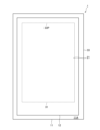
- FIG. 1 is a plan view schematically illustrating a solar battery beacon according to the first embodiment.
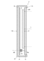
- FIG. 2 is a cross-sectional view schematically illustrating the solar battery beacon of the first embodiment.
- the solar cell beacon 1 of the first embodiment illustrated in FIGS. 1 and 2 converts the light L that irradiates the solar cell beacon 1 into electric power, operates with the electric power, and emits radio waves RW.
- the radio waves RW are radio waves for positioning, and the solar cell beacon 1 provides positioning functions by transmitting radio waves for positioning.
- the radio waves RW may be radio waves other than radio waves for positioning, and the solar cell beacon 1 may provide functions other than the positioning function.
- the solar battery beacon 1 is installed in an area with sufficient illuminance and transmits radio waves RW toward areas without sufficient illuminance. This allows the solar beacon 1 to provide positioning functionality in areas that do not have sufficient illumination.
- the solar battery beacon 1 is installed in a room where a lighting device is installed. Therefore, the light L is mainly light emitted by the lighting device. However, the light L may be light other than the light emitted by the illumination. For example, the light L may be sunlight.
- the radio wave RW is a radio wave conforming to the Bluetooth (registered trademark) Low Energy (BLE) standard. Therefore, the radio wave RW has a frequency belonging to the frequency band of 2.4 GHz. However, the radio wave RW may have a frequency that does not belong to the 2.4 GHz frequency band.
- Radio waves RW are received by smartphones and used for positioning by smartphones.
- the radio waves RW may be received by terminals other than smartphones, and may be used for purposes other than positioning.
- the solar battery beacon 1 includes a solar battery beacon main body 11 and a radio wave absorption/reflector 12 .
- the solar cell beacon main body 11 has a plate-like shape. For this reason, the solar battery beacon body 11 has a first principal surface 11A and a second principal surface 11B. The second main surface 11B is on the side opposite to the side on which the first main surface 11A is present.
- the first main surface 11A includes a light receiving surface 21. As shown in FIG.
- the solar battery beacon main body 11 converts the light L that irradiates the light receiving surface 21 into electric power, operates with the electric power, and emits radio waves RW.
- the solar battery beacon main body 11 may have a shape other than the plate-like shape.
- the radio wave absorber/reflector 12 has a plate-like shape.
- the radio wave absorber/reflector 12 is arranged on the first main surface 11A.
- the radio wave absorbing/reflecting portion 12 may contact the first main surface 11A or may not contact the first main surface 11A. Therefore, there may be no space between the radio wave absorbing/reflecting portion 12 and the first main surface 11A, or there may be a space between the radio wave absorbing/reflecting portion 12 and the first main surface 11A.
- the radio wave absorber/reflector 12 is arranged on the light receiving surface 21 of the solar cell beacon main body 11 to cover the light receiving surface 21 .
- the radio wave absorber/reflector 12 may cover the entire light receiving surface 21 or only a portion of the light receiving surface 21 as long as the intensity of the radio wave RW can be reduced by 5 dBm or more, as will be described later. . Therefore, the area occupied by the radio wave absorbing/reflecting portion 12 may be equal to or larger than the area of the light receiving surface 21 or may be smaller than the area of the light receiving surface 21 .
- the radio wave absorber/reflector 12 may have a shape other than the plate shape.
- the radio wave absorbing/reflecting part 12 is attached to the first main surface of the solar battery beacon main body 11 by adhesion with an adhesive substance, fixing by fixing members such as screws and clips, fitting into grooves formed in the solar battery beacon main body 11, and the like. 11A.
- the radio wave absorption/reflection part 12 is transparent. Therefore, the radio wave absorbing/reflecting portion 12 transmits the light L in the thickness direction of the radio wave absorbing/reflecting portion 12 .
- the transmitted light L irradiates the light receiving surface 21 .
- the radio wave absorber/reflector 12 absorbs or reflects the radio wave RW and controls the directivity of the radio wave RW.
- the solar cell beacon 1 emits radio waves RW in the direction in which the second main surface 11B of the solar cell beacon main body 11 where the radio wave absorbing/reflecting part 12 is not arranged faces. Therefore, the solar battery beacon 1 transmits radio waves RW in the direction opposite to the direction in which the light receiving surface 21 of the solar battery beacon main body 11 faces. This allows the solar battery beacon 1 installed in an area with sufficient illuminance to transmit radio waves RW to an area without sufficient illuminance.
- radio wave absorption/reflection parts are colored. Therefore, when the radio wave absorbing/reflecting portion covering the light receiving surface 21 of the solar cell beacon main body 11 is made of a general radio wave absorbing/reflecting portion, the light receiving surface 21 is prevented from receiving the light L. However, in the first embodiment, since the radio wave absorbing/reflecting portion 12 covering the light receiving surface 21 is transparent, the light receiving surface 21 does not prevent the light L from being received by the second solar cell beacon main body 11. A radio wave RW can be transmitted in the direction in which the main surface 11B faces.
- the solar battery beacon main body 11 includes a solar battery 31 , a transmitter 32 and a housing 33 .
- the solar cell 31 has a light receiving surface 21 and converts the light L received by the light receiving surface 21 into electric power to generate power.
- Solar cell 31 is not particularly limited, but is preferably a dye-sensitized solar cell with high energy conversion efficiency.
- the transmitting device 32 operates with the generated power and transmits radio waves RW.
- the housing 33 accommodates the solar cell 31 and the transmission device 32 .
- the housing 33 is formed with an opening 33P.
- Light receiving surface 21 of solar cell 31 is exposed to the outside of housing 33 through opening 33P.
- the radio wave absorber/reflector 12 is arranged on the outer surface of the housing 33 and closes the opening 33P.
- the radio wave absorber/reflector 12 may not block the opening 33P.
- the transmitting device 32 includes a circuit board 41 and an antenna 42 .
- the circuit board 41 generates high frequency power.
- the antenna 42 is mounted on the circuit board 41.
- the antenna 42 converts the generated high-frequency power into radio waves RW and radiates the radio waves RW.
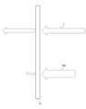
- FIG. 3 is a side view schematically illustrating the radio wave absorber/reflector provided in the solar cell beacon of the first embodiment.
- the radio wave absorber/reflector 12 absorbs or reflects the radio wave RW and reduces the intensity of the radio wave RW by 5 dBm or more. Therefore, the intensity of the radio wave RW reaching the receiving location when the radio wave absorbing/reflecting unit 12 is arranged in the propagation path of the radio wave RW is the same as that of the receiving location when the radio wave absorbing/reflecting unit 12 is not arranged in the propagation path of the radio wave RW.
- the intensity of the radio wave RW reaching the receiving location when the radio wave RW passes through the radio wave absorbing/reflecting portion 12 is the intensity of the radio wave RW reaching the receiving location when the radio wave RW does not pass through the radio wave absorbing/reflecting portion 12. 5 dBm or more lower than
- the radio wave absorber/reflector 12 transmits the light L and has a visible light transmittance of 10% or more.
- Light L is visible light having a wavelength of 370-780 nm.
- the radio wave absorber/reflector 12 is solid.
- the radio wave absorbing/reflecting portion 12 includes at least one selected from the group consisting of, for example, a transparent conductive film and a semiconductor film.
- the transparent conductive film is, for example, a group consisting of indium tin oxide (ITO), fluorine-doped tin oxide (FTO), zinc oxide (ZnO), tin oxide (SnO 2 ), titanium oxide (TiO 2 ), metal thin films and carbon nanotubes.
- the semiconductor film contains, for example, at least one selected from the group consisting of gallium nitride (GaN) and silicon carbide (SiC).
- the solar battery beacon 1 may have a transparent layer sandwiching the radio wave absorbing/reflecting part 12 .
- the transparent layer is made of resin, glass, or the like.
- the resin includes, for example, at least one selected from the group consisting of acrylic resin (PMMA), polyethylene terephthalate (PET) resin and polycarbonate (PC) resin.
- FIG. 4 is a cross-sectional view schematically illustrating a solar battery beacon of a first modification of the first embodiment.
- the radio wave absorbing/reflecting portion 12 is arranged on the second main surface 11B.
- the solar battery beacon 1M mainly emits radio waves RW in the direction in which the first main surface 11A of the solar battery beacon main body 11 where the radio wave absorbing/reflecting part 12 is not arranged faces.
- the radio wave absorbing/reflecting portion 12 is arranged on the second main surface 11B, the radio wave absorbing/reflecting portion 12 does not have to be transparent.
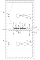
- FIG. 5 is a cross-sectional view schematically illustrating a usage example of the solar cell beacon of the first embodiment.
- a first lighting device 55 capable of illuminating the first area 53 is installed in the first area 53
- a second lighting device 55 capable of illuminating the second area 54 is installed in the second area 54 .
- lighting device 56 is installed.
- the first lighting device 55 is turned on to illuminate the first area 53
- the second lighting device 56 is turned off to illuminate the second area 54 . do not have. Therefore, the first area 53 has sufficient illuminance, but the second area 54 does not have sufficient illuminance.
- a first smartphone 57 for positioning exists in the first area 53
- a second smartphone 58 for positioning exists in the second area 54 .
- the first smart phone 57 may be replaced with a device other than a smart phone.
- the second smart phone 58 may be replaced with a device other than a smart phone.
- the partition 52 has a first wall surface 52A and a second wall surface 52B.
- the first wall surface 52A faces the first area 53 and is illuminated by the first lighting device 55, and the second wall surface 52B faces the second area 54 and is not illuminated.
- Solar cell beacons 1 and 1M are attached on the first wall surface 52A of the partition 52.
- the solar battery beacon 1 is mounted on the first wall surface 52A of the partition 52 so that the second main surface 11B of the solar battery beacon body 11 faces the first wall surface 52A.
- the light receiving surface 21 of the solar cell beacon main body 11 faces the first area 53 having sufficient illuminance.
- the solar battery beacon 1 can convert the first light L1 that irradiates the first area 53 into electric power, generate electric power, operate with the generated electric power, and transmit the first radio waves RW1. can.
- the second main surface 11B of the solar cell beacon body 11 on which the radio wave absorbing/reflecting part 12 is not installed faces the second area 54 .
- the solar battery beacon 1 can transmit the first radio wave RW1 toward the second area 54 that does not have sufficient illuminance.
- the second smartphone 58 existing in the second area 54 which could not be positioned conventionally, can perform positioning.
- the solar battery beacon 1M is also mounted on the first wall surface 52A of the partition 52 so that the second main surface 11B of the solar battery beacon body 11 faces the first wall surface 52A.
- the light receiving surface 21 of the solar cell beacon main body 11 faces the first area 53 having sufficient illuminance.
- the solar battery beacon 1M can convert the first light L1 that irradiates the first area 53 into electric power, generate electric power, operate with the generated electric power, and transmit the second radio waves RW2. can.
- the first main surface 11A of the solar battery beacon main body 11 on which the radio wave absorbing/reflecting part 12 is not installed faces the first area 53.
- the solar cell beacon 1M can transmit the second radio wave RW2 toward the first area 53 having sufficient illuminance.
- the first smartphone 57 existing in the first area 53 can perform positioning.
- FIG. 6 is a cross-sectional view schematically illustrating the solar battery beacon of the second embodiment.
- a housing 33 accommodates the radio wave absorbing/reflecting part 12.
- Radio wave absorber/reflector 12 is arranged on light receiving surface 21 of solar cell 31 .
- FIG. 7 is a cross-sectional view schematically illustrating a solar cell beacon of a first modified example of the second embodiment.
- the solar battery beacon 2M of the first modification of the second embodiment illustrated in FIG. placed in The solar battery beacon 2M mainly emits radio waves RW in the direction in which the first main surface 11A of the solar battery beacon main body 11 where the radio wave absorbing/reflecting part 12 is not arranged faces. If the radio wave absorber/reflector 12 is arranged between the transmitting device 32 and the second principal surface 11B, the radio wave absorber/reflector 12 may not be transparent.
- FIG. 8 is a perspective view schematically illustrating the solar cell beacon of the third embodiment.
- the solar battery beacon 3 of the third embodiment illustrated in FIG. 1 is the solar battery beacon 3 of the third embodiment illustrated in FIG.
- the transparent case 13 is formed with an accommodation space 13S capable of accommodating the solar cell beacon main body 11 .
- the transparent case 13 is transparent and made of acrylic resin, for example.
- the radio wave absorber/reflector 12 is attached to the transparent case 13.
- the solar cell beacon main body 11 can be inserted into and removed from the transparent case 13 .
- the solar battery beacon main body 11 When the solar battery beacon main body 11 is inserted into the transparent case 13, the solar battery beacon main body 11 is accommodated in the accommodation space 13S. Also, the radio wave absorbing/reflecting part 12 is arranged on the first main surface 11A of the solar cell beacon main body 11 . Therefore, when the solar battery beacon main body 11 is inserted into the transparent case 13 , the radio wave absorbing/reflecting part 12 is arranged on the light receiving surface 21 of the solar battery beacon main body 11 to cover the light receiving surface 21 . This facilitates switching between a state in which the radio wave absorbing/reflecting portion 12 covers the light receiving surface 21 and a state in which the radio wave absorbing/reflecting portion 12 does not cover the light receiving surface 21 .
- FIG. 9 is a cross-sectional view schematically illustrating the solar cell beacon of the fourth embodiment.
- the radio wave absorbing/reflecting portion 12 is liquid.
- the solar cell beacon 4 also includes a transparent container 14 .
- the radio wave absorber/reflector 12 contains, for example, at least one selected from the group consisting of water, ethyl alcohol, methyl alcohol, ethylene glycol and glycerin.
- Ethyl alcohol, methyl alcohol, ethylene glycol and glycerin are examples of alcohols.
- Water, ethyl alcohol, methyl alcohol, ethylene glycol and glycerin are examples of substances with hydroxyl groups.
- FIG. 10 is a graph showing the relationship between dielectric loss tangent tan ⁇ , dielectric constant ⁇ ' and penetration depth D of each substance at 2.45 GHz.
- the horizontal axis of the graph in FIG. 10 represents the dielectric loss tangent tan ⁇
- the vertical axis of the graph in FIG. 10 represents the dielectric constant ⁇ '.
- points indicating the dielectric loss tangent tan ⁇ and the dielectric constant ⁇ ' of each material are plotted, and a line indicating the dielectric loss tangent tan ⁇ and the dielectric constant ⁇ ' giving each penetration depth D is drawn.
- the penetration depth D is the depth at which the microwave power is attenuated by half.
- the penetration depth D is expressed by Equation (1) using the frequency f [Hz], relative permittivity ⁇ r and dielectric loss tangent tan ⁇ .
- the material constituting the radio wave absorbing/reflecting part 12 In order for the radio wave absorbing/reflecting part 12 to reduce the intensity of the radio wave RW by 5 dBm or more, the material constituting the radio wave absorbing/reflecting part 12 must have a penetration depth D of 0.03 m or less at the frequency of the radio wave RW. is. Then, referring to FIG. 10, it can be understood that water, ethyl alcohol, methyl alcohol, ethylene glycol and glycerin mentioned above can be mentioned as substances having a penetration depth D of 0.03 m or less at 2.45 GHz. can.
- the dielectric loss factor ⁇ ′′ is obtained from the product ⁇ r ⁇ tan ⁇ of the dielectric constant ⁇ r (dielectric constant ⁇ ′) and the dielectric loss tangent tan ⁇ . ' and the dielectric loss factor ⁇ '' are shown in Table 1.
- a housing space 14S for housing the radio wave absorbing/reflecting section 12 is formed in the transparent container 14 .
- the transparent container 14 is arranged on the first main surface 11A of the solar cell beacon main body 11 .
- the radio wave absorbing/reflecting part 12 is arranged on the light receiving surface 21 of the solar cell beacon main body 11 and covers the light receiving surface 21 .
- the radio wave absorbing/reflecting part 12 transmits the light L in the thickness direction, absorbs or reflects the radio wave RW, and controls the directivity of the radio wave RW.
- the transparent container 14 is transparent and made of, for example, resin or glass.
- the resin includes, for example, at least one selected from the group consisting of acrylic resin (PMMA), polyethylene terephthalate (PET) resin and polycarbonate (PC) resin.
- FIG. 11 is a cross-sectional view schematically illustrating an experimental device for measuring the received signal strength indicator (RSSI) of radio waves emitted by a solar battery beacon that does not have a radio wave absorption/reflection part.
- FIG. 12 is a cross-sectional view schematically illustrating an experimental device for measuring RSSI of radio waves emitted by a solar cell beacon having a radio wave absorbing/reflecting part.
- RSSI received signal strength indicator
- a radio wave receiver 61 1 m away from the solar cell beacon 4A without the radio wave absorbing/reflecting unit 12 receives the radio wave RW4A transmitted by the solar cell beacon 4A.
- a radio wave receiver 61 1 m away from the solar cell beacon 4B having the radio wave absorbing/reflecting part 12 receives the radio wave RW4B transmitted by the solar cell beacon 4B.
- the radio wave absorber/reflector 12 has a thickness of 1.5 cm.
- FIG. 13 is a graph showing changes in RSSI over time, measured using the experimental device shown in FIG. 11, when the solar battery beacon does not include a radio wave absorbing/reflecting part.
- FIG. 14 is a graph showing changes in RSSI over time, measured using the experimental apparatus shown in FIG. 12, when the solar cell beacon has a radio wave absorption/reflection portion and the radio wave absorption/reflection portion is pure water. be.
- the radio wave absorbing/reflecting part 12 made of pure water reduces the RSSI by about 15 dbm.
- the radio wave absorption/reflection part 12 contains a solvent and a solute.
- a solute is dissolved in a solvent.
- the solvent includes, for example, at least one selected from the group consisting of water, ethyl alcohol, methyl alcohol, ethylene glycol and glycerin.
- the solute includes, for example, at least one selected from the group consisting of electrolytes and sucrose. Electrolytes include, for example, sodium chloride (NaCl).
- Fig. 15 is a graph showing the relationship between temperature, dielectric constant ⁇ ' and dielectric loss factor ⁇ " of 1% agar gel containing NaCl at various concentrations.
- Fig. 16 is a graph showing 1% agar gel containing sucrose at various concentrations.
- 2 is a graph showing the relationship between the temperature of , the dielectric constant ⁇ ′ and the dielectric loss factor ⁇ ′′.
- FIG. 17 is a graph showing changes in RSSI over time, measured using the experimental apparatus shown in FIG. 12, when the solar cell beacon has a radio wave absorption/reflection portion and the radio wave absorption/reflection portion is pure water.
- FIG. 18 shows changes in RSSI over time, measured using the experimental apparatus shown in FIG. 12, when the solar cell beacon has a radio wave absorption/reflection part and the radio wave absorption/reflection part is a 23% NaCl aqueous solution. graph.
- FIG. 19 is a cross-sectional view schematically illustrating the solar battery beacon of the sixth embodiment.
- a solar cell beacon 6 of the sixth embodiment illustrated in FIG. 19 includes a first antireflection film 15 .
- a first antireflection film 15 is attached to the outer surface 14A of the transparent container 14 . Thereby, the reflection of the light L on the outer surface 14A can be suppressed. Thereby, the visible light transmittance of the radio wave absorber/reflector including the radio wave absorber/reflector 12 and the transparent container 14 can be increased.
- FIG. 20 is a cross-sectional view schematically illustrating a solar cell beacon of a first modified example of the sixth embodiment.
- a solar cell beacon 6M of a first modified example of the sixth embodiment illustrated in FIG. 20 includes a second antireflection film 16 in addition to the first antireflection film 15.
- a second antireflection film 16 is attached to the inner surface 14B of the transparent container 14 . Thereby, the reflection of the light L on the inner surface 14B can be suppressed. Thereby, the visible light transmittance of the radio wave absorber/reflector including the radio wave absorber/reflector 12 and the transparent container 14 can be increased.
- the second antireflection film 16 is not attached to the inner surface 14B of the transparent container 14. Therefore, the radio wave absorbing/reflecting portion 12 and the transparent container 14 form an interface on the inner surface 14B.
- the difference between the refractive index of the radio wave absorbing/reflecting portion 12 and the refractive index of the transparent container 14 is 2.0 or less.
- radio wave absorption/reflection Part 12 consists of water with a refractive index of 1.33.
- a refractive liquid for example, is used to adjust the refractive index of the liquid.
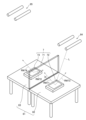
- FIG. 21 is a perspective view schematically illustrating a beacon system according to a seventh embodiment.
- the beacon system 7 of the seventh embodiment illustrated in FIG. 21 includes a screen 71, a first solar battery beacon 72 and a second solar battery beacon 73.
- the screen 71 divides the room 81 into a first area 82 and a second area 83 .
- the screen 71 is also called a partition or the like.
- a first lighting device 84 capable of illuminating the first area 82 is installed in the first area 82, and a first lighting device 84 capable of illuminating the second area 83 is installed in the second area 83.
- a second lighting device 85 is installed. However, for energy saving, the first lighting device 84 is turned on to illuminate the first area 82, while the second lighting device 85 is turned off to illuminate the second area 83. do not have.
- the screen 71 has a radio wave absorbing/reflecting part similar to the radio wave absorbing/reflecting part 12 provided in the solar cell beacon 1 of the first embodiment. Therefore, the screen 71 hardly transmits a radio wave RW71 traveling from the first area 82 to the second area 83 and hardly transmits a radio wave RW72 traveling from the second area 83 to the first area 82 . Thereby, the screen 71 controls the directivity of radio waves emitted by the first solar cell beacon 72 and the second solar cell beacon 73 . However, the screen 71 transmits light traveling from the first area 82 to the second area 83 and transmits light traveling from the second area 83 to the first area 82 . Thereby, the first lighting device 84 can also illuminate the second area 83 to some extent.
- Each of the first solar cell beacon 72 and the second solar cell beacon 73 includes a solar cell 31 , a transmitter 32 and a housing 33 .
- a first solar beacon 72 is installed in a first area 82 and a second solar beacon 73 is installed in a second area 83 .
- the first solar cell beacon 72 receives light L emitted by a first lighting device 84 installed in the first area 82 and transmits a first radio wave RW73 within the first area 82 .
- the first solar beacon 72 thereby provides positioning functionality to the first area 82 .
- the second solar battery beacon 73 receives the light L emitted by the first lighting device 84 installed in the first area 82 through the screen 71, and emits the second radio wave in the second area 83. Send RW74.
- the second solar beacon 73 provides the positioning function to the second area 83 .
- the screen 71 having the radio wave absorbing/reflecting part 12 the directivity of the radio waves emitted by the first solar battery beacon 72 and the second solar battery beacon 73 is controlled, and positioning is performed for each area partitioned by the screen 71. function can be provided. Further, since the radio wave absorbing/reflecting portion 12 provided in the screen 71 is transparent, the screen 71 does not prevent the illuminance of the partitioned area from being sufficiently high.
Landscapes
- Engineering & Computer Science (AREA)
- Physics & Mathematics (AREA)
- General Physics & Mathematics (AREA)
- Radar, Positioning & Navigation (AREA)
- Remote Sensing (AREA)
- Power Engineering (AREA)
- Computer Networks & Wireless Communication (AREA)
- Microelectronics & Electronic Packaging (AREA)
- Electromagnetism (AREA)
- Photovoltaic Devices (AREA)
Abstract
太陽電池ビーコンは、電力を発電する太陽電池と、前記電力により動作して電波を発信する発信装置と、透明であり前記電波を吸収又は反射する電波吸収/反射部と、を備える。
Description
本開示は、太陽電池ビーコン及びビーコンシステムに関する。本願は、2021年11月30日に、日本に出願された特願2021-193696号に基づく優先権を主張するものであり、その内容をここに援用する。
太陽電池ビーコンは、照明装置により放射された光等を電力に変換する太陽電池を備える。太陽電池ビーコンは、当該電力により動作して電波を発信する。
太陽電池ビーコンは、電力を放電する一次電池を備えるビーコンと比較して、電池の交換が不要でありメンテナンスの手間を大幅に削減することができるという利点を有する。
一方で、太陽電池ビーコンが電波を発信することができるか否かは、太陽電池ビーコンを照射する光の照度に依存する。このため、太陽電池に電波を発信させるためには、当該光の照度を十分な照度とする必要がある。
特許文献1は、ビーコンを開示する。当該ビーコンは、アンテナが実装された基板及び電波吸収体を備える。アンテナは、信号波を放射する。電波吸収体は、基板の側面、背面、正面等に配置される。基板の正面に配置される電波吸収体は、アンテナから放射された信号波の一部を通過させる開口を有する(段落[0059]及び[0060])。
照明装置が設置された室内であっても、照明装置により放射された光が十分に届かず十分な照度を有しないエリアが存在することがある。
当該エリアに設置された太陽電池ビーコンは、電波を発信することができず、当該エリアに機能を提供することができない。例えば、太陽電池ビーコンが、測位のための電波を発信して設置されたエリアに測位機能を提供するビーコンである場合は、当該エリアに設置された太陽電池ビーコンは、測位のための電波を発信することができず、当該エリアに測位機能を提供することができない。
本開示は、この問題に鑑みてなされた。本開示の一態様は、例えば、十分な照度を有しないエリアに機能を提供することができる太陽電池ビーコンを提供することを目的とする。
本開示の一態様の太陽電池ビーコンは、電力を発電する太陽電池と、前記電力により動作して電波を発信する発信装置と、透明であり前記電波を吸収又は反射する電波吸収/反射部と、を備える。
本開示の他の一態様のビーコンシステムは、電力を発電する太陽電池と、前記電力により動作して電波を発信する発信装置と、を備える太陽電池ビーコンと、透明であり前記電波を吸収又は反射する電波吸収/反射部を備える衝立と、を備える。
以下、本開示の実施形態について、図面を参照しつつ説明する。なお、図面については、同一又は同等の要素には同一の符号を付し、重複する説明は省略する。
1 第1実施形態
1.1 太陽電池ビーコンの概略
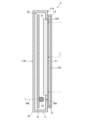
図1は、第1実施形態の太陽電池ビーコンを模式的に図示する平面図である。図2は、第1実施形態の太陽電池ビーコンを模式的に図示する断面図である。
1.1 太陽電池ビーコンの概略
図1は、第1実施形態の太陽電池ビーコンを模式的に図示する平面図である。図2は、第1実施形態の太陽電池ビーコンを模式的に図示する断面図である。
図1及び図2に図示される第1実施形態の太陽電池ビーコン1は、太陽電池ビーコン1を照射する光Lを電力に変換し、当該電力により動作して電波RWを発信する。
電波RWは、測位のための電波であり、太陽電池ビーコン1は、測位のための電波を発信して測位機能を提供する。ただし、電波RWが、測位のための電波以外の電波であってもよく、太陽電池ビーコン1が、測位機能以外の機能を提供してもよい。
太陽電池ビーコン1は、十分な照度を有するエリアに設置され、十分な照度を有しないエリアに向けて電波RWを発信する。これにより、太陽電池ビーコン1は、十分な照度を有しないエリアに測位機能を提供する。
太陽電池ビーコン1は、照明装置が設置された室内に設置される。このため、光Lは、主に、当該照明装置により放射される光である。ただし、光Lが、当該照明により放射される光以外の光であってもよい。例えば、光Lが、太陽光であってもよい。
電波RWは、ブルートゥース(登録商標)・ロー・エナジー(BLE)の規格に準拠した電波である。このため、電波RWは、2.4GHzの周波数帯に属する周波数を有する。ただし、電波RWが、2.4GHzの周波数帯に属しない周波数を有してもよい。
電波RWは、スマートフォンにより受信され、スマートフォンによる測位に用いられる。電波RWが、スマートフォン以外の端末により受信されてもよく、測位以外の用途に用いられてもよい。
1.2 太陽電池ビーコンの構成
図1及び図2に図示されるように、太陽電池ビーコン1は、太陽電池ビーコン本体11及び電波吸収/反射部12を備える。
図1及び図2に図示されるように、太陽電池ビーコン1は、太陽電池ビーコン本体11及び電波吸収/反射部12を備える。
太陽電池ビーコン本体11は、板状の形状を有する。このため、太陽電池ビーコン本体11は、第1の主面11A及び第2の主面11Bを有する。第2の主面11Bは、第1の主面11Aがある側と反対の側にある。第1の主面11Aは、受光面21を含む。太陽電池ビーコン本体11は、受光面21を照射する光Lを電力に変換し、当該電力により動作して電波RWを発信する。太陽電池ビーコン本体11が、板状の形状以外の形状を有してもよい。
電波吸収/反射部12は、板状の形状を有する。電波吸収/反射部12は、第1の主面11Aの上に配置される。電波吸収/反射部12は、第1の主面11Aに接触してもよいし、第1の主面11Aに接触しなくてもよい。したがって、電波吸収/反射部12と第1の主面11Aとの間に空間が存在しなくてもよいし、電波吸収/反射部12と第1の主面11Aとの間に空間が存在してもよい。電波吸収/反射部12は、太陽電池ビーコン本体11の受光面21の上に配置され、受光面21を覆う。電波吸収/反射部12は、後述するように電波RWの強度を5dBm以上低下させることができる限り、受光面21の全体を覆ってもよいし、受光面21の一部のみを覆ってもよい。したがって、電波吸収/反射部12が占める面積は、受光面21の面積以上であってもよいし、受光面21の面積より小さくてもよい。電波吸収/反射部12が、板状の形状以外の形状を有してもよい。
電波吸収/反射部12は、粘着物質による接着、ねじ、クリップ等の固定部材による固定、太陽電池ビーコン本体11に形成された溝へのはめ込み等により、太陽電池ビーコン本体11の第1の主面11Aに取り付けられる。
電波吸収/反射部12は、透明である。このため、電波吸収/反射部12は、電波吸収/反射部12の厚さ方向に光Lを透過させる。透過させられた光Lは、受光面21を照射する。
電波吸収/反射部12は、電波RWを吸収又は反射し、電波RWの指向性を制御する。これにより、太陽電池ビーコン1は、電波吸収/反射部12が配置されない太陽電池ビーコン本体11の第2の主面11Bが向く方向に電波RWを発信する。したがって、太陽電池ビーコン1は、太陽電池ビーコン本体11の受光面21が向く方向と反対の方向に電波RWを発信する。これにより、十分な照度を有するエリアに設置された太陽電池ビーコン1に、十分な照度を有しないエリアに向けて電波RWを発信させることができる。
一般的な電波吸収/反射部には、色が着いている。このため、太陽電池ビーコン本体11の受光面21を覆う電波吸収/反射部が一般的な電波吸収/反射部からなる場合は、受光面21が光Lを受光することが阻害される。しかし、第1実施形態においては、受光面21を覆う電波吸収/反射部12が透明であるため、受光面21が光Lを受光することを阻害することなく太陽電池ビーコン本体11の第2の主面11Bが向く方向に電波RWを発信することができる。
1.3 太陽電池ビーコン本体
図1及び図2に図示されるように、太陽電池ビーコン本体11は、太陽電池31、発信装置32及びハウジング33を備える。
図1及び図2に図示されるように、太陽電池ビーコン本体11は、太陽電池31、発信装置32及びハウジング33を備える。
太陽電池31は、受光面21を有し、受光面21により受光された光Lを電力に変換して電力を発電する。太陽電池31は、特に制限されないが、望ましくは、高いエネルギー変換効率を有する色素増感太陽電池である。
発信装置32は、発電された電力により動作して電波RWを発信する。
ハウジング33は、太陽電池31及び発信装置32を収容する。ハウジング33には、開口33Pが形成される。太陽電池31の受光面21は、開口33Pからハウジング33の外部に向かって露出する。電波吸収/反射部12は、ハウジング33の外面の上に配置されて開口33Pを塞ぐ。電波吸収/反射部12が開口33Pを塞がなくてもよい。
1.4 発信装置
図2に図示されるように、発信装置32は、回路基板41及びアンテナ42を備える。
図2に図示されるように、発信装置32は、回路基板41及びアンテナ42を備える。
回路基板41は、高周波電力を生成する。
アンテナ42は、回路基板41の上に実装される。アンテナ42は、生成された高周波電力を電波RWに変換して電波RWを放射する。
1.5 電波吸収/反射部
図3は、第1実施形態の太陽電池ビーコンに備えられる電波吸収/反射部を模式的に図示する側面図である。
図3は、第1実施形態の太陽電池ビーコンに備えられる電波吸収/反射部を模式的に図示する側面図である。
電波吸収/反射部12は、電波RWを吸収又は反射し、電波RWの強度を5dBm以上低下させる。したがって、電波RWの伝搬経路に電波吸収/反射部12が配置された場合に受信場所に到達する電波RWの強度は、電波RWの伝搬経路に電波吸収/反射部12が配置されない場合に受信場所に到達する電波RWの強度より5dBm以上低い。すなわち、電波RWが電波吸収/反射部12を透過する場合に受信場所に到達する電波RWの強度は、電波RWが電波吸収/反射部12を透過しない場合に受信場所に到達する電波RWの強度より5dBm以上低い。
電波吸収/反射部12は、光Lを透過させ、10%以上の可視光透過率を有する。光Lは、370~780nmの波長を有する可視光である。
電波吸収/反射部12は、固体である。電波吸収/反射部12が固体である場合は、電波吸収/反射部12は、例えば、透明導電膜及び半導体膜からなる群より選択される少なくとも1種を含む。透明導電膜は、例えば、酸化インジウムスズ(ITO)、フッ素ドープ酸化スズ(FTO)、酸化亜鉛(ZnO)、酸化スズ(SnO2)、酸化チタン(TiO2)、金属薄膜及びカーボンナノチューブからなる群より選択される少なくとも1種を含む。半導体膜は、例えば、窒化ガリウム(GaN)及び炭化ケイ素(SiC)からなる群より選択される少なくとも1種を含む。
太陽電池ビーコン1が、電波吸収/反射部12を挟む透明層を備えてもよい。透明層は、樹脂、ガラス等からなる。樹脂は、例えば、アクリル樹脂(PMMA)、ポリエチレンテレフタレート(PET)樹脂及びポリカーボネート(PC)樹脂からなる群より選択される少なくとも1種を含む。
1.6 変形例
図4は、第1実施形態の第1変形例の太陽電池ビーコンを模式的に図示する断面図である。
図4は、第1実施形態の第1変形例の太陽電池ビーコンを模式的に図示する断面図である。
図4に図示される第1実施形態の第1変形例の太陽電池ビーコン1Mにおいては、電波吸収/反射部12が、第2の主面11Bの上に配置される。太陽電池ビーコン1Mは、主に電波吸収/反射部12が配置されない太陽電池ビーコン本体11の第1の主面11Aが向く方向に電波RWを発信する。電波吸収/反射部12が第2の主面11Bの上に配置される場合は、電波吸収/反射部12が透明でなくてもよい。
1.7 太陽ビーコンの使用例
図5は、第1実施形態の太陽電池ビーコンの使用例を模式的に図示する断面図である。
図5は、第1実施形態の太陽電池ビーコンの使用例を模式的に図示する断面図である。
図5に図示される第1実施形態の太陽電池ビーコン1及び1Mの使用例においては、室内51がパーティション52により第1のエリア53及び第2のエリア54に仕切られる。
第1のエリア53には、第1のエリア53を照明することができる第1の照明装置55が設置され、第2のエリア54には、第2のエリア54を照明することができる第2の照明装置56が設置されている。ただし、省エネルギーのために、第1の照明装置55は、点灯されて第1のエリア53を照明しているが、第2の照明装置56は、消灯されて第2のエリア54を照明していない。このため、第1のエリア53は、十分な照度を有するが、第2のエリア54は、十分な照度を有しない。
第1のエリア53には、測位を行う第1のスマートフォン57が存在しており、第2のエリア54には、測位を行う第2のスマートフォン58が存在している。第1のスマートフォン57が、スマートフォン以外の機器に置き換えられてもよい。第2のスマートフォン58が、スマートフォン以外の機器に置き換えられてもよい。
パーティション52は、第1の壁面52A及び第2の壁面52Bを有する。第1の壁面52Aは、第1のエリア53に面し、第1の照明装置55により照明され、第2の壁面52Bは、第2のエリア54に面し、照明されない。
パーティション52の第1の壁面52Aの上には、太陽電池ビーコン1及び1Mが取り付けられる。
太陽電池ビーコン1は、太陽電池ビーコン本体11の第2の主面11Bがパーティション52の第1の壁面52Aに対向するように第1の壁面52Aの上に取り付けられる。
これにより、太陽電池ビーコン1においては、太陽電池ビーコン本体11の受光面21が、十分な照度を有する第1のエリア53を向く。これにより、太陽電池ビーコン1は、第1のエリア53を照射する第1の光L1を電力に変換して電力を発電し、発電した電力により動作して第1の電波RW1を発信することができる。
また、太陽電池ビーコン1においては、電波吸収/反射部12が設置されない太陽電池ビーコン本体11の第2の主面11Bが、第2のエリア54を向く。これにより、太陽電池ビーコン1は、十分な照度を有しない第2のエリア54に向けて第1の電波RW1を発信することができる。これにより、従来測位を行うことができなかった第2のエリア54に存在する第2のスマートフォン58は、測位を行うことができる。
太陽電池ビーコン1Mも、太陽電池ビーコン本体11の第2の主面11Bがパーティション52の第1の壁面52Aに対向するように第1の壁面52Aの上に取り付けられる。
これにより、太陽電池ビーコン1Mにおいては、太陽電池ビーコン本体11の受光面21が、十分な照度を有する第1のエリア53を向く。これにより、太陽電池ビーコン1Mは、第1のエリア53を照射する第1の光L1を電力に変換して電力を発電し、発電した電力により動作して第2の電波RW2を発信することができる。
また、太陽電池ビーコン1Mにおいては、電波吸収/反射部12が設置されない太陽電池ビーコン本体11の第1の主面11Aが、第1のエリア53を向く。これにより、太陽電池ビーコン1Mは、十分な照度を有する第1のエリア53に向けて第2の電波RW2を発信することができる。これにより、第1のエリア53に存在する第1のスマートフォン57は、測位を行うことができる。
2 第2実施形態
以下では、第2実施形態が第1実施形態と相違する点が説明される。説明されない点については、第1実施形態において採用される構成と同様の構成が第2実施形態においても採用される。第1実施形態以外の実施形態において採用される構成と同様の構成が第2実施形態において採用されてもよい。
以下では、第2実施形態が第1実施形態と相違する点が説明される。説明されない点については、第1実施形態において採用される構成と同様の構成が第2実施形態においても採用される。第1実施形態以外の実施形態において採用される構成と同様の構成が第2実施形態において採用されてもよい。
図6は、第2実施形態の太陽電池ビーコンを模式的に図示する断面図である。
図6に図示される第2実施形態の太陽電池ビーコン2においては、ハウジング33が電波吸収/反射部12を収容する。電波吸収/反射部12は、太陽電池31の受光面21の上に配置される。
特許文献1に開示されるビーコンと同様に透明でない電波吸収材が太陽電池31と発信装置32との間に配置された場合は、太陽電池31と発信装置32とを電気的に接続するための開口が電波吸収材に形成される必要がある。しかし、太陽電池ビーコン2においては、太陽電池31と発信装置32との間ではなく太陽電池31の受光面21の上に電波吸収/反射部12が配置されるため、太陽電池31と発信装置32とを電気的に接続するための開口が電波吸収/反射部12に形成される必要がない。このため、電波吸収/反射部12を太陽電池ビーコン2に組み込むことは容易である。
図7は、第2実施形態の第1変形例の太陽電池ビーコンを模式的に図示する断面図である。
図7に図示される第2実施形態の第1変形例の太陽電池ビーコン2Mにおいては、電波吸収/反射部12が、発信装置32と太陽電池ビーコン本体11の第2の主面11Bとの間に配置される。太陽電池ビーコン2Mは、主に電波吸収/反射部12が配置されない太陽電池ビーコン本体11の第1の主面11Aが向く方向に電波RWを発信する。電波吸収/反射部12が発信装置32と第2の主面11Bとの間に配置される場合は、電波吸収/反射部12が透明でなくてもよい。
3 第3実施形態
以下では、第3実施形態が第1実施形態と相違する点が説明される。説明されない点については、第1実施形態において採用される構成と同様の構成が第3実施形態においても採用される。第1実施形態以外の実施形態において採用される構成と同様の構成が第3実施形態において採用されてもよい。
以下では、第3実施形態が第1実施形態と相違する点が説明される。説明されない点については、第1実施形態において採用される構成と同様の構成が第3実施形態においても採用される。第1実施形態以外の実施形態において採用される構成と同様の構成が第3実施形態において採用されてもよい。
図8は、第3実施形態の太陽電池ビーコンを模式的に図示する斜視図である。
図8に図示される第3実施形態の太陽電池ビーコン3は、太陽電池ビーコン本体11、電波吸収/反射部12及び透明ケース13を備える。
透明ケース13には、太陽電池ビーコン本体11を収容することができる収容空間13Sが形成される。透明ケース13は、透明であり、例えば、アクリル樹脂からなる。
電波吸収/反射部12は、透明ケース13に取り付けられる。
太陽電池ビーコン本体11は、透明ケース13に対して挿抜可能である。
太陽電池ビーコン本体11が透明ケース13に対して挿入された場合は、太陽電池ビーコン本体11が、収容空間13Sに収容される。また、電波吸収/反射部12が、太陽電池ビーコン本体11の第1の主面11Aの上に配置される。このため、太陽電池ビーコン本体11が透明ケース13に対して挿入された場合は、電波吸収/反射部12は、太陽電池ビーコン本体11の受光面21の上に配置され、受光面21を覆う。これにより、電波吸収/反射部12が受光面21を覆う状態と電波吸収/反射部12が受光面21を覆わない状態とを切り替えることが容易になる。
4 第4実施形態
以下では、第4実施形態が第1実施形態と相違する点が説明される。説明されない点については、第1実施形態において採用される構成と同様の構成が第4実施形態においても採用される。第1実施形態以外の実施形態において採用される構成と同様の構成が第4実施形態において採用されてもよい。
以下では、第4実施形態が第1実施形態と相違する点が説明される。説明されない点については、第1実施形態において採用される構成と同様の構成が第4実施形態においても採用される。第1実施形態以外の実施形態において採用される構成と同様の構成が第4実施形態において採用されてもよい。
図9は、第4実施形態の太陽電池ビーコンを模式的に図示する断面図である。
図9に図示される第4実施形態の太陽電池ビーコン4においては、電波吸収/反射部12が、液体である。また、太陽電池ビーコン4は、透明容器14を備える。
電波吸収/反射部12は、例えば、水、エチルアルコール、メチルアルコール、エチレングリコール及びグリセリンからなる群より選択される少なくとも1種を含む。エチルアルコール、メチルアルコール、エチレングリコール及びグリセリンは、アルコールの例である。水、エチルアルコール、メチルアルコール、エチレングリコール及びグリセリンは、水酸基を有する物質の例である。
以下では、電波吸収/反射部12を構成する物質の選定について説明する。
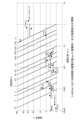
図10は、2.45GHzにおける各物質の誘電正接tanδ、誘電率ε’及び浸透深さDの関係を示すグラフである。
図10のグラフの横軸には、誘電正接tanδがとられており、図10のグラフの縦軸には、誘電率ε’がとられている。図10のグラフ内には、各物質の誘電正接tanδ及び誘電率ε’を示す点がプロットされており、各浸透深さDを与える誘電正接tanδ及び誘電率ε’を示す線が引かれている。
浸透深さDは、マイクロ波の電力が半分に減衰する深さである。浸透深さDは、周波数f[Hz]、比誘電率εr及び誘電正接tanδを用いて、式(1)により表される。

電波吸収/反射部12が電波RWの強度を5dBm以上低下させるためには、電波RWの周波数において電波吸収/反射部12を構成する物質が0.03m以下の浸透深さDを有することが必要である。そして、図10を参照すると、2.45GHzにおいて0.03m以下の浸透深さDを有する物質として、先述した水、エチルアルコール、メチルアルコール、エチレングリコール及びグリセリンを挙げることができることを理解することができる。
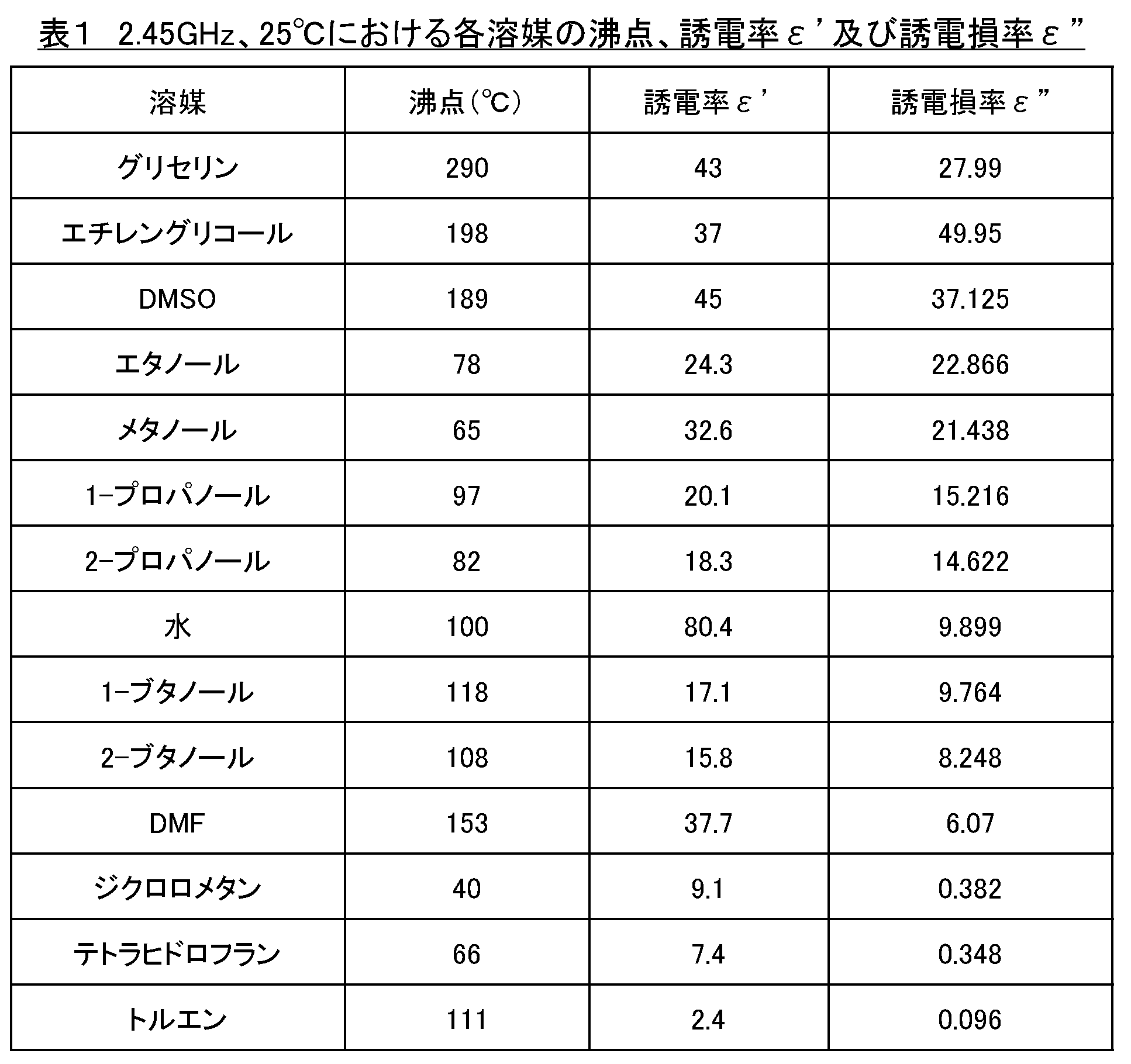
誘電損率ε”は、誘電率εr(誘電率ε’)と誘電正接tanδとの積εr×tanδから求められる。参考として、2.45GHz、25℃における各溶媒の沸点、誘電率ε’及び誘電損率ε”を表1に示す。
透明容器14には、電波吸収/反射部12を収容する収容空間14Sが形成される。透明容器14は、太陽電池ビーコン本体11の第1の主面11Aの上に配置される。これにより、電波吸収/反射部12は、太陽電池ビーコン本体11の受光面21の上に配置され、受光面21を覆う。これにより、電波吸収/反射部12は、厚さ方向に光Lを透過させ、電波RWを吸収又は反射し、電波RWの指向性を制御する。
透明容器14は、透明であり、例えば、樹脂、ガラス等からなる。樹脂は、例えば、アクリル樹脂(PMMA)、ポリエチレンテレフタレート(PET)樹脂及びポリカーボネート(PC)樹脂からなる群より選択される少なくとも1種を含む。
図11は、電波吸収/反射部を備えない太陽電池ビーコンにより発信された電波の受信信号強度(RSSI)を測定するための実験装置を模式的に図示する断面図である。図12は、電波吸収/反射部を備える太陽電池ビーコンにより発信された電波のRSSIを測定するための実験装置を模式的に図示する断面図である。
図11に図示される実験装置においては、電波吸収/反射部12を備えない太陽電池ビーコン4Aから1m離れた電波受信機61が、太陽電池ビーコン4Aにより発信された電波RW4Aを受信している。図12に図示される実験装置においては、電波吸収/反射部12を備える太陽電池ビーコン4Bから1m離れた電波受信機61が、太陽電池ビーコン4Bにより発信された電波RW4Bを受信している。電波吸収/反射部12は、1.5cmの厚さを有する。
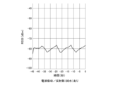
図13は、図11に図示される実験装置を用いて測定された、太陽電池ビーコンが電波吸収/反射部を備えない場合のRSSIの時間変化を示すグラフである。図14は、図12に図示される実験装置を用いて測定された、太陽電池ビーコンが電波吸収/反射部を備え電波吸収/反射部が純水である場合のRSSIの時間変化を示すグラフである。
図13及び図14からは、純水である電波吸収/反射部12は、RSSIを約15dbm低下させることを理解することができる。
5 第5実施形態
以下では、第5実施形態が第4実施形態と相違する点が説明される。説明されない点については、第4実施形態において採用される構成と同様の構成が第5実施形態においても採用される。第4実施形態以外の実施形態において採用される構成と同様の構成が第5実施形態において採用されてもよい。
以下では、第5実施形態が第4実施形態と相違する点が説明される。説明されない点については、第4実施形態において採用される構成と同様の構成が第5実施形態においても採用される。第4実施形態以外の実施形態において採用される構成と同様の構成が第5実施形態において採用されてもよい。
第5実施形態の太陽電池ビーコンにおいては、電波吸収/反射部12が、溶媒及び溶質を含む。溶質は、溶媒に溶解している。溶媒は、例えば、水、エチルアルコール、メチルアルコール、エチレングリコール及びグリセリンからなる群より選択される少なくとも1種を含む。溶質は、例えば、電解質及びショ糖からなる群より選択される少なくとも1種を含む。電解質は、例えば、塩化ナトリウム(NaCl)を含む。
図15は、各濃度のNaClを含む1%寒天ゲルの温度、誘電率ε’及び誘電損率ε”の関係を示すグラフである。図16は、各濃度のショ糖を含む1%寒天ゲルの温度、誘電率ε’及び誘電損率ε”の関係を示すグラフである。
図15からは、NaClの濃度が高くなるほど、誘電損率ε”が高くなることを理解することができる。また、図16からは、ショ糖の濃度が高くなるほど、誘電損率ε”が高くなることを理解することができる。これらのことから、NaCl、ショ糖等の溶質の濃度が高くなるほど、誘電損率ε”が高くなり、電波吸収/反射部12による電波RWの吸収量が大きくなることを理解することができる。
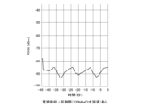
図17は、図12に図示される実験装置を用いて測定された、太陽電池ビーコンが電波吸収/反射部を備え電波吸収/反射部が純水である場合のRSSIの時間変化を示すグラフである。図18は、図12に図示される実験装置を用いて測定された、太陽電池ビーコンが電波吸収/反射部を備え電波吸収/反射部が23%NaCl水溶液である場合のRSSIの時間変化を示すグラフである。
図17及び図18からは、NaClは、RSSIを低下させることを理解することができる。
6 第6実施形態
以下では、第6実施形態が第4実施形態と相違する点が説明される。説明されない点については、第4実施形態において採用される構成と同様の構成が第6実施形態においても採用される。第4実施形態以外の実施形態において採用される構成と同様の構成が第6実施形態において採用されてもよい。
以下では、第6実施形態が第4実施形態と相違する点が説明される。説明されない点については、第4実施形態において採用される構成と同様の構成が第6実施形態においても採用される。第4実施形態以外の実施形態において採用される構成と同様の構成が第6実施形態において採用されてもよい。
図19は、第6実施形態の太陽電池ビーコンを模式的に図示する断面図である。
図19に図示される第6実施形態の太陽電池ビーコン6は、第1の反射防止フィルム15を備える。第1の反射防止フィルム15は、透明容器14の外面14Aに貼られる。これにより、外面14Aにおける光Lの反射を抑制することができる。これにより、電波吸収/反射部12及び透明容器14を備える電波吸収/反射体の可視光透過率を高くすることができる。
図20は、第6実施形態の第1変形例の太陽電池ビーコンを模式的に図示する断面図である。
図20に図示される第6実施形態の第1変形例の太陽電池ビーコン6Mは、第1の反射防止フィルム15に加えて第2の反射防止フィルム16を備える。第2の反射防止フィルム16は、透明容器14の内面14Bに貼られる。これにより、内面14Bにおける光Lの反射を抑制することができる。これにより、電波吸収/反射部12及び透明容器14を備える電波吸収/反射体の可視光透過率を高くすることができる。
太陽電池ビーコン6においては、透明容器14の内面14Bに第2の反射防止フィルム16が貼られない。このため、内面14Bにおいて、電波吸収/反射部12と透明容器14とが界面を形成する。この場合は、望ましくは、電波吸収/反射部12の屈折率と透明容器14の屈折率との差が2.0以下とされる。例えば、透明容器14が屈折率1.49のアクリル樹脂、屈折率1.64のポリエチレンテレフタレート樹脂、屈折率1.58のポリカーボネート樹脂又は屈折率1.51のガラスからなる場合は、電波吸収/反射部12は、屈折率1.33の水からなる。これにより、内面14Bに第2の反射防止フィルム16が貼られていなくても、内面14Bにおける光Lの反射を抑制することができる。液体の屈折率の調整には、例えば、屈折液が用いられる。
7 第7実施形態
図21は、第7実施形態のビーコンシステムを模式的に図示する斜視図である。
図21は、第7実施形態のビーコンシステムを模式的に図示する斜視図である。
図21に図示される第7実施形態のビーコンシステム7は、衝立71、第1の太陽電池ビーコン72及び第2の太陽電池ビーコン73を備える。
衝立71は、室内81を第1のエリア82及び第2のエリア83に仕切る。衝立71は、パーティション等とも呼ばれる。
第1のエリア82には、第1のエリア82を照明することができる第1の照明装置84が設置されており、第2のエリア83には、第2のエリア83を照明することができる第2の照明装置85が設置されている。ただし、省エネルギーのために、第1の照明装置84は、点灯されて第1のエリア82を照明しているが、第2の照明装置85は、消灯されて第2のエリア83を照明していない。
衝立71は、第1実施形態の太陽電池ビーコン1に備えられる電波吸収/反射部12と同様の電波吸収/反射部を備える。このため、衝立71は、第1のエリア82から第2のエリア83へ向かう電波RW71をほとんど透過させず、第2のエリア83から第1のエリア82へ向かう電波RW72をほとんど透過させない。これにより、衝立71は、第1の太陽電池ビーコン72及び第2の太陽電池ビーコン73により発信される電波の指向性を制御する。ただし、衝立71は、第1のエリア82から第2のエリア83へ向かう光を透過させ、第2のエリア83から第1のエリア82へ向かう光を透過させる。これにより、第1の照明装置84は、第2のエリア83もある程度照明することができる。
第1の太陽電池ビーコン72及び第2の太陽電池ビーコン73の各々は、太陽電池31、発信装置32及びハウジング33を備える。第1の太陽電池ビーコン72は、第1のエリア82に設置され、第2の太陽電池ビーコン73は、第2のエリア83に設置される。第1の太陽電池ビーコン72は、第1のエリア82に設置された第1の照明装置84により放射された光Lを受光し、第1のエリア82内に第1の電波RW73を発信する。これにより、第1の太陽電池ビーコン72は、第1のエリア82に測位機能を提供する。第2の太陽電池ビーコン73は、第1のエリア82に設置された第1の照明装置84により放射された光Lを衝立71を介して受光し、第2のエリア83内に第2の電波RW74を発信する。これにより、第2の太陽電池ビーコン73は、第2のエリア83に測位機能を提供する。
電波吸収/反射部12を備える衝立71によれば、第1の太陽電池ビーコン72及び第2の太陽電池ビーコン73により発信される電波の指向性を制御して衝立71により仕切られるエリアごとに測位機能を提供することができる。また、衝立71に備えられる電波吸収/反射部12は、透明であるため、衝立71は、仕切られるエリアの照度を十分なものとすることを妨げない。
Claims (16)
- 電力を発電する太陽電池と、
前記電力により動作して電波を発信する発信装置と、
透明であり前記電波を吸収又は反射する電波吸収/反射部と、
を備える太陽電池ビーコン。 - 前記太陽電池は、光を受光する受光面を有し、前記光を前記電力に変換し、
前記電波吸収/反射部は、前記受光面の上に配置される
請求項1に記載の太陽電池ビーコン。 - 前記電波吸収/反射部は、前記電波の強度を5dBm以上低下させる
請求項1又は2に記載の太陽電池ビーコン。 - 前記電波吸収/反射部は、10%以上の可視光透過率を有する
請求項1から3までのいずれかに記載の太陽電池ビーコン。 - 前記電波吸収/反射部は、酸化インジウムスズ、フッ素ドープ酸化スズ、酸化亜鉛、酸化スズ、酸化チタン、金属薄膜、カーボンナノチューブ、窒化ガリウム及び炭化ケイ素からなる群より選択される少なくとも1種を含む
請求項1から4までのいずれかに記載の太陽電池ビーコン。 - 前記電波吸収/反射部は、液体であり、
前記電波吸収/反射部を収容する透明容器を備える
請求項1から4までのいずれかに記載の太陽電池ビーコン。 - 前記電波吸収/反射部は、水、エチルアルコール、メチルアルコール、エチレングリコール及びグリセリンからなる群より選択される少なくとも1種を含む
請求項6に記載の太陽電池ビーコン。 - 前記電波吸収/反射部は、溶媒と、前記溶媒に溶解した溶質と、を含む
請求項6又は7に記載の太陽電池ビーコン。 - 前記溶質は、電解質及びショ糖からなる群より選択される少なくとも1種を含む
請求項8に記載の太陽電池ビーコン。 - 前記透明容器の外面に貼られる第1の反射防止フィルムを備える
請求項6から9までのいずれかに記載の太陽電池ビーコン。 - 前記透明容器の内面に貼られる第2の反射防止フィルムを備える
請求項10に記載の太陽電池ビーコン。 - 前記電波吸収/反射部と前記透明容器とが界面を形成し、
前記電波吸収/反射部の屈折率と前記透明容器の屈折率との差が2.0以下である
請求項10に記載の太陽電池ビーコン。 - 前記太陽電池及び前記発信装置を収容するハウジングを備え、
前記電波吸収/反射部は、前記ハウジングの外面の上に配置される
請求項1から12までのいずれかに記載の太陽電池ビーコン。 - 前記太陽電池、前記発信装置及び前記電波吸収/反射部を収容するハウジングを備える請求項1から12までのいずれかに記載の太陽電池ビーコン。
- 透明ケースと、
前記太陽電池及び前記発信装置を備え、前記透明ケースに対して挿抜可能な太陽電池ビーコン本体と、
を備え、
前記電波吸収/反射部は、前記透明ケースに取り付けられる
請求項1から14までのいずれかに記載の太陽電池ビーコン。 - 電力を発電する太陽電池と、前記電力により動作して電波を発信する発信装置と、を備える太陽電池ビーコンと、
透明であり前記電波を吸収又は反射する電波吸収/反射部を備える衝立と、
を備えるビーコンシステム。
Applications Claiming Priority (2)
| Application Number | Priority Date | Filing Date | Title |
|---|---|---|---|
| JP2021-193696 | 2021-11-30 | ||
| JP2021193696 | 2021-11-30 |
Publications (1)
| Publication Number | Publication Date |
|---|---|
| WO2023100554A1 true WO2023100554A1 (ja) | 2023-06-08 |
Family
ID=86611941
Family Applications (1)
| Application Number | Title | Priority Date | Filing Date |
|---|---|---|---|
| PCT/JP2022/040090 Ceased WO2023100554A1 (ja) | 2021-11-30 | 2022-10-27 | 太陽電池ビーコン及びビーコンシステム |
Country Status (1)
| Country | Link |
|---|---|
| WO (1) | WO2023100554A1 (ja) |
Citations (8)
| Publication number | Priority date | Publication date | Assignee | Title |
|---|---|---|---|---|
| JP2001320224A (ja) * | 2000-05-10 | 2001-11-16 | Nippon Telegr & Teleph Corp <Ntt> | アンテナ光起電力素子一体化装置 |
| JP2002076769A (ja) * | 2000-08-30 | 2002-03-15 | Shigeo Kawasaki | 能動素子アンテナ |
| JP2011060872A (ja) * | 2009-09-08 | 2011-03-24 | Ig Kogyo Kk | 透光性電波吸収体 |
| JP2015106814A (ja) * | 2013-11-29 | 2015-06-08 | 東京エレクトロニツクシステムズ株式会社 | 電波送信装置及び位置測定システム |
| US20150260823A1 (en) * | 2014-03-11 | 2015-09-17 | Crestron Electronics, Inc. | Method of enclosing and powering a bluetooth emitter |
| JP2015190979A (ja) * | 2014-03-27 | 2015-11-02 | パナソニック インテレクチュアル プロパティ コーポレーション オブアメリカPanasonic Intellectual Property Corporation of America | 位置計測方法、位置計測プログラム及び無線装置 |
| WO2019098068A1 (ja) * | 2017-11-17 | 2019-05-23 | 日本電産株式会社 | ビーコンネットワーク、移動体測位システムおよび物流管理システム |
| WO2019107514A1 (ja) * | 2017-12-01 | 2019-06-06 | Agc株式会社 | アンテナユニット、およびアンテナ付きガラス板 |
-
2022
- 2022-10-27 WO PCT/JP2022/040090 patent/WO2023100554A1/ja not_active Ceased
Patent Citations (8)
| Publication number | Priority date | Publication date | Assignee | Title |
|---|---|---|---|---|
| JP2001320224A (ja) * | 2000-05-10 | 2001-11-16 | Nippon Telegr & Teleph Corp <Ntt> | アンテナ光起電力素子一体化装置 |
| JP2002076769A (ja) * | 2000-08-30 | 2002-03-15 | Shigeo Kawasaki | 能動素子アンテナ |
| JP2011060872A (ja) * | 2009-09-08 | 2011-03-24 | Ig Kogyo Kk | 透光性電波吸収体 |
| JP2015106814A (ja) * | 2013-11-29 | 2015-06-08 | 東京エレクトロニツクシステムズ株式会社 | 電波送信装置及び位置測定システム |
| US20150260823A1 (en) * | 2014-03-11 | 2015-09-17 | Crestron Electronics, Inc. | Method of enclosing and powering a bluetooth emitter |
| JP2015190979A (ja) * | 2014-03-27 | 2015-11-02 | パナソニック インテレクチュアル プロパティ コーポレーション オブアメリカPanasonic Intellectual Property Corporation of America | 位置計測方法、位置計測プログラム及び無線装置 |
| WO2019098068A1 (ja) * | 2017-11-17 | 2019-05-23 | 日本電産株式会社 | ビーコンネットワーク、移動体測位システムおよび物流管理システム |
| WO2019107514A1 (ja) * | 2017-12-01 | 2019-06-06 | Agc株式会社 | アンテナユニット、およびアンテナ付きガラス板 |
Similar Documents
| Publication | Publication Date | Title |
|---|---|---|
| CN100402774C (zh) | 采用太阳能电池的发光砌块 | |
| US20140376076A1 (en) | Vehicle lamp with electrochromic element | |
| US8919987B2 (en) | LED display unit with solar panels and LED display device including same | |
| US9837852B1 (en) | Harnessing front light in e-readers to generate electricity | |
| CN101583823A (zh) | 照明设备 | |
| TWI599827B (zh) | 顯示裝置 | |
| WO2023100554A1 (ja) | 太陽電池ビーコン及びビーコンシステム | |
| CN201764322U (zh) | 一种带金属杯状散热导光罩的led筒灯 | |
| CN211372075U (zh) | 一种具有防水性能的均匀发光的导光结构及摄像机 | |
| US20100232145A1 (en) | Portable light with integral-designed light source body | |
| CN211345166U (zh) | 一种全透明汽车转向灯 | |
| CN217426152U (zh) | 一种带有补光结构的人脸识别机 | |
| CN208566449U (zh) | 一种可显示电量的便携式投光灯 | |
| CN220171715U (zh) | 一种灯光模组 | |
| CN204477905U (zh) | 一种发光均匀的太阳能平板照明装置 | |
| CN202972916U (zh) | 一种屋顶照明的光学系统 | |
| CN217825242U (zh) | 一种具有照明功能的扩音器 | |
| CN201764295U (zh) | 具有反光罩的led灯管 | |
| KR102701165B1 (ko) | 태양광 패널을 갖는 led 조명 장치 | |
| CN221975070U (zh) | 灯盖及汽车尾灯 | |
| CN212618031U (zh) | 一种具有氛围功能的太阳能路灯 | |
| CN224080147U (zh) | 一种光能充电灯具 | |
| CN216901231U (zh) | 背光模组及显示装置 | |
| CN105276511A (zh) | 一种发光均匀的太阳能平板照明装置 | |
| CN211180773U (zh) | 鼠标 |
Legal Events
| Date | Code | Title | Description |
|---|---|---|---|
| 121 | Ep: the epo has been informed by wipo that ep was designated in this application |
Ref document number: 22900987 Country of ref document: EP Kind code of ref document: A1 |
|
| NENP | Non-entry into the national phase |
Ref country code: DE |
|
| 122 | Ep: pct application non-entry in european phase |
Ref document number: 22900987 Country of ref document: EP Kind code of ref document: A1 |
|
| NENP | Non-entry into the national phase |
Ref country code: JP |