WO2023100382A1 - Storage box and opening/closing device - Google Patents
Storage box and opening/closing device Download PDFInfo
- Publication number
- WO2023100382A1 WO2023100382A1 PCT/JP2022/006520 JP2022006520W WO2023100382A1 WO 2023100382 A1 WO2023100382 A1 WO 2023100382A1 JP 2022006520 W JP2022006520 W JP 2022006520W WO 2023100382 A1 WO2023100382 A1 WO 2023100382A1
- Authority
- WO
- WIPO (PCT)
- Prior art keywords
- storage box
- pressure
- pressure release
- movable portion
- closed position
- Prior art date
Links
- 238000007789 sealing Methods 0.000 claims abstract description 3
- 238000004804 winding Methods 0.000 claims description 22
- 230000000149 penetrating effect Effects 0.000 claims description 3
- 230000005484 gravity Effects 0.000 description 20
- 230000005489 elastic deformation Effects 0.000 description 5
- 230000000630 rising effect Effects 0.000 description 5
- 238000010586 diagram Methods 0.000 description 4
- 238000000034 method Methods 0.000 description 4
- 238000006243 chemical reaction Methods 0.000 description 3
- 230000000694 effects Effects 0.000 description 3
- 239000000463 material Substances 0.000 description 3
- 229910052751 metal Inorganic materials 0.000 description 3
- 239000002184 metal Substances 0.000 description 3
- 229920005989 resin Polymers 0.000 description 3
- 239000011347 resin Substances 0.000 description 3
- 239000000126 substance Substances 0.000 description 3
- XEEYBQQBJWHFJM-UHFFFAOYSA-N Iron Chemical compound [Fe] XEEYBQQBJWHFJM-UHFFFAOYSA-N 0.000 description 2
- 230000004048 modification Effects 0.000 description 2
- 238000012986 modification Methods 0.000 description 2
- 239000013585 weight reducing agent Substances 0.000 description 2
- RYGMFSIKBFXOCR-UHFFFAOYSA-N Copper Chemical compound [Cu] RYGMFSIKBFXOCR-UHFFFAOYSA-N 0.000 description 1
- CWYNVVGOOAEACU-UHFFFAOYSA-N Fe2+ Chemical compound [Fe+2] CWYNVVGOOAEACU-UHFFFAOYSA-N 0.000 description 1
- 230000009471 action Effects 0.000 description 1
- 230000002411 adverse Effects 0.000 description 1
- 229910052782 aluminium Inorganic materials 0.000 description 1
- XAGFODPZIPBFFR-UHFFFAOYSA-N aluminium Chemical compound [Al] XAGFODPZIPBFFR-UHFFFAOYSA-N 0.000 description 1
- 239000004760 aramid Substances 0.000 description 1
- 229920003235 aromatic polyamide Polymers 0.000 description 1
- 238000005452 bending Methods 0.000 description 1
- 229910052802 copper Inorganic materials 0.000 description 1
- 239000010949 copper Substances 0.000 description 1
- 230000007423 decrease Effects 0.000 description 1
- 230000001934 delay Effects 0.000 description 1
- 238000007599 discharging Methods 0.000 description 1
- 238000006073 displacement reaction Methods 0.000 description 1
- 239000000428 dust Substances 0.000 description 1
- 238000005516 engineering process Methods 0.000 description 1
- 239000003822 epoxy resin Substances 0.000 description 1
- 238000000605 extraction Methods 0.000 description 1
- 239000011810 insulating material Substances 0.000 description 1
- 229910052742 iron Inorganic materials 0.000 description 1
- 239000007769 metal material Substances 0.000 description 1
- 230000002093 peripheral effect Effects 0.000 description 1
- 229920000647 polyepoxide Polymers 0.000 description 1
- 229920013716 polyethylene resin Polymers 0.000 description 1
- 229920005594 polymer fiber Polymers 0.000 description 1
- 238000005381 potential energy Methods 0.000 description 1
- 230000001681 protective effect Effects 0.000 description 1
- 230000035939 shock Effects 0.000 description 1
- 229910001220 stainless steel Inorganic materials 0.000 description 1
- 239000010935 stainless steel Substances 0.000 description 1
- 229920005992 thermoplastic resin Polymers 0.000 description 1
- 229920001187 thermosetting polymer Polymers 0.000 description 1
- 230000007704 transition Effects 0.000 description 1
Images


Classifications
-
- H—ELECTRICITY
- H01—ELECTRIC ELEMENTS
- H01H—ELECTRIC SWITCHES; RELAYS; SELECTORS; EMERGENCY PROTECTIVE DEVICES
- H01H33/00—High-tension or heavy-current switches with arc-extinguishing or arc-preventing means
- H01H33/02—Details
- H01H33/53—Cases; Reservoirs, tanks, piping or valves, for arc-extinguishing fluid; Accessories therefor, e.g. safety arrangements, pressure relief devices
- H01H33/56—Gas reservoirs
-
- H—ELECTRICITY
- H02—GENERATION; CONVERSION OR DISTRIBUTION OF ELECTRIC POWER
- H02B—BOARDS, SUBSTATIONS OR SWITCHING ARRANGEMENTS FOR THE SUPPLY OR DISTRIBUTION OF ELECTRIC POWER
- H02B1/00—Frameworks, boards, panels, desks, casings; Details of substations or switching arrangements
- H02B1/26—Casings; Parts thereof or accessories therefor
- H02B1/28—Casings; Parts thereof or accessories therefor dustproof, splashproof, drip-proof, waterproof or flameproof
-
- H—ELECTRICITY
- H02—GENERATION; CONVERSION OR DISTRIBUTION OF ELECTRIC POWER
- H02B—BOARDS, SUBSTATIONS OR SWITCHING ARRANGEMENTS FOR THE SUPPLY OR DISTRIBUTION OF ELECTRIC POWER
- H02B13/00—Arrangement of switchgear in which switches are enclosed in, or structurally associated with, a casing, e.g. cubicle
- H02B13/02—Arrangement of switchgear in which switches are enclosed in, or structurally associated with, a casing, e.g. cubicle with metal casing
- H02B13/025—Safety arrangements, e.g. in case of excessive pressure or fire due to electrical defect
Definitions
- This application relates to storage boxes and opening/closing devices.
- a switchgear includes a switch and a storage box such as a protective box that stores the switch and prevents the switch from being exposed to foreign matter such as rain or dust.
- This storage box is configured to have a high airtightness in order to prevent foreign matter from entering the interior.
- the storage box is provided with a pressure release device for preventing the pressure increase when the current is interrupted.
- the pressure relief device is configured to prevent a sudden increase in pressure inside the storage box by releasing the gas inside the storage box to the outside when the current is interrupted while maintaining the sealability of the storage box except when the current is interrupted. be.
- a pressure release hole formed in the storage box and a pressure release lid that opens the pressure release hole when the current is interrupted and seals the pressure release hole when the current is not interrupted. is disclosed (see, for example, Patent Document 1).
- an O-ring mounting member is provided around the pressure-releasing hole to form a convex shape
- the pressure-releasing lid is formed in a concave shape so as to cover the pressure-releasing hole, including the O-ring mounting member. It is The pressure-releasing lid utilizes the relationship between the elastic force of the torsion coil spring and the increase in internal pressure when the current is interrupted, and transitions between the open position and the closed position.
- the pressure release lid is provided with a locked member for holding the position in the closed position.
- the pressure-releasing lid is held in a closed position by locking the member to be locked with a locking member provided in the pressure-releasing hole, and foreign matter can be prevented from entering the storage box.
- the present application discloses a technique for solving the above-described problems, and provides a storage box and an opening/closing device capable of reducing the weight of the storage box while preventing foreign matter from entering the storage box.
- the purpose is to
- the storage box disclosed in the present application is a storage box in which a switch is housed, a pressure release hole is provided in the side wall for releasing the internal pressure, and a pressure release device for the switch is attached to the side wall.
- the pressure release device of the container includes a movable part that can move between a closed position that seals the pressure release hole and an open position that opens the pressure release hole, and an elastically deformable part that deforms according to the movement of the movable part.
- the elastic force of the deformation portion applies a load to the movable portion in the direction of returning to the closed position when the movable portion is in the open position.
- FIG. 1 Another form of the storage box disclosed in the present application is a storage box in which a switch is stored, a pressure release hole for releasing the internal pressure is provided in the side wall, and a pressure release device for the switch is attached to the side wall.
- the box, the pressure release device of the switch has a movable part that rotates around one end as a central axis and can move between a closed position that seals the pressure release hole and an open position that opens the pressure release hole.
- a torsion coil spring that applies a load to the movable part in a direction to hold it in the closed position when it is in the open position, and a torsion coil spring that applies a load to the movable part in a direction to return to the closed position when the movable part is in the open position; has a flat plate-like portion and an arm provided at one end of the plate-like portion and provided with a hole into which a shaft is fitted, and rotates with the shaft as a whole.
- the storage box disclosed in the present application it is possible to reduce the weight of the storage box while preventing foreign matter from entering the storage box.
- FIG. 1 is a perspective view of an opening/closing device according to Embodiment 1.
- FIG. 1 is a front view of a pressure relief device according to Embodiment 1.
- FIG. 2 is an exploded view of the parts of the pressure relief device according to Embodiment 1;
- 1 is a front view of a pressure relief plate according to Embodiment 1;
- FIG. 4 is a front view showing another example of the pressure relief plate according to Embodiment 1;
- FIG. 4 is a front view showing another example of the pressure relief plate according to Embodiment 1;
- FIG. FIG. 4 is a perspective view illustrating a method of fixing the torsion coil spring according to Embodiment 1;
- FIG. 2 is a sectional view taken along line AA of the pressure relief device according to Embodiment 1, showing a state in which the pressure relief plate is in the closed position;
- FIG. 2 is a sectional view taken along line AA of the pressure relief device according to Embodiment 1, showing a state in which the pressure relief plate is at the open position;
- FIG. 10 is a diagram for explaining the return operation of the pressure relief plate;
- FIG. 10 is a sectional view taken along line AA of the pressure relief device according to Embodiment 2, showing a state in which the pressure relief plate is in the closed position;
- FIG. 10 is a sectional view taken along line AA of the pressure relief device according to Embodiment 2, showing a state in which the pressure relief plate is at the open position;
- FIG. 11 is a cross-sectional view of the pressure relief device according to Embodiment 3, taken along the line AA.
- FIG. 11 is a front view of a pressure relief device according to Embodiment 4;
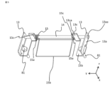
- FIG. 1 is a perspective view of an opening/closing device according to Embodiment 1.
- the switchgear 1000 includes, for example, a power switch 100 and a storage box 91 such as a protection box that stores the switch.
- the storage box 91 is, for example, a two-tiered box body, and has a highly airtight structure so as to prevent foreign matter from entering the inside.
- coordinate axes are set as follows. That is, the vertical direction is the z-axis, and the x-axis and the y-axis are set in a direction perpendicular to the z-axis, that is, in the horizontal direction.
- the x-axis is set along the long side direction of the storage box 91
- the y-axis is set along the short side direction of the storage box 91 .
- the upward direction is the +z-axis direction
- the downward direction is the -z-axis direction.
- the x-axis and the y-axis as shown in FIG. 1, one side is the +x-axis direction and the +y-axis direction, and the opposite direction is the -x-axis direction and the -y-axis direction positive direction.
- the upper part 91A of the storage box has a trapezoidal cross section so that the top side is narrower.
- the shape of the storage box 91 is not limited to that shown in FIG.
- Pressure relief devices 10A and 10B are attached to the outer side surfaces of side walls 91Aa along the short side direction (y-axis direction) of the upper portion 91A.
- a pressure release hole is provided in the side wall 91Aa at a position where the pressure release device is attached.
- two pressure release devices are attached to each side wall 91Aa on both sides, but the number and attachment positions of the pressure release devices to be attached are not particularly limited.
- the pressure release device 10 may be attached to the side wall 91Ab along the long side direction (x-axis direction) of the storage box 91 .
- a side wall 91Bb along the long side direction (x-axis direction) is provided with a hole (not shown) through which the busbar 92 passes.
- the pressure release device 10A will be described as an example.
- FIG. 2 is a front view of the pressure relief device according to Embodiment 1, and is a diagram when the pressure relief device 10A is viewed in the +x-axis direction of FIG. Since the same applies to the pressure relief device 10B, it will be simply referred to as the pressure relief device 10 hereinafter.
- the pressure relief device 10 is attached to a pressure relief device attachment portion 91d provided at a predetermined position on the side wall 91Aa.
- the position and range of the pressure release device mounting portion 91d are not particularly limited as long as the pressure release hole 91c formed in the side wall 91Aa and a screw hole required for mounting the pressure release device 10 can be formed.
- the pressure-releasing device 10 includes a pressure-releasing plate 11 covering the pressure-releasing hole 91c, a cover 12 covering the pressure-releasing plate 11, and two plate-like members arranged on both sides of the movable portion 11c of the pressure-releasing plate 11 in the y-axis direction.
- the pressure relief plate 11 has the same outer shape as the cover 12, and is configured to prevent a gap from occurring between the cover 12 and the pressure relief device attachment portion 91d when the pressure relief plate 11 is attached to the pressure relief device attachment portion 91d together with the cover 12. It has become.
- a U-shaped slit 11a is provided in the pressure release plate 11, and a movable portion 11c is provided in a range surrounded by the U-shaped slit 11a.
- the movable portion 11c moves between a closed position in which the pressure release hole 91c is closed by closely contacting the side wall 91Aa and an open position in which the pressure release hole 91c is opened by separating from the side wall 91Aa. in position. Therefore, the position and range of the movable portion 11c must be configured so that at least the pressure release hole 91c can be sealed.
- a more detailed configuration of the pressure relief plate 11 will be described later.
- the cover 12 is attached to the pressure release device attachment portion 91d. Although not shown in FIG. 2, the cover 12 has an opening corresponding to the movable portion 11c. Moreover, a grippable handle portion 12 a is integrally provided on the upper portion of the cover 12 . The handle portion 12a is configured by projecting both ends in the y-axis direction of the upper portion of the cover 12 upward and connecting the projecting portions on both sides.
- the support 13 is integrally fixed to the storage box 91 with the pressure relief plate 11 and the cover 12 by fastening members such as bolts and nuts.
- the shaft 14 is rotatably supported by the support 13 by passing through the through hole 13aa. Further, axial displacement of the shaft 14 is restricted by interference with the inner wall of the cover 12 at both ends in the axial direction, so that the shaft 14 is prevented from falling out of the through hole 13aa.
- the torsion coil spring 15 has a pressing portion 15 b that applies the load due to the elastic force of the torsion coil spring 15 to the movable portion 11 c of the pressure release plate 11 .
- FIG. 3 is an exploded view of the parts of the pressure relief device according to Embodiment 1, and the dashed-dotted line in FIG.
- a hole 91e into which the bolt 81 is inserted is provided at a predetermined position of the pressure release device mounting portion 91d.
- the pressure relief device 10 is attached to the storage box 91 (pressure relief device attachment portion 91d) as follows. First, as shown in FIG. 3, the support 13 with the torsion coil spring 15 and the shaft 14 attached thereto is inserted into the cover 12 through the opening 12b provided at the lower end of the cover 12 to form one component. .
- the pressure relief plate 11 is arranged so as to be sandwiched between the components (cover 12, support 13, shaft 14, and torsion coil spring 15) and the pressure relief device mounting portion 91d, and bolts 81 and nuts 82 are used to secure the pressure relief plate 11.
- Each component is attached to the pressure relief device mounting portion 91d by fastening and fixing the above components and the pressure relief plate 11 with a screw.
- the opening 12c of the cover 12 and the movable portion 11c of the pressure release plate 11 are aligned.
- the side surface of the cover 12 on the side of the pressure release device mounting portion 91d is brought into close contact with the pressure release device mounting portion 91d except for the opening 12c.
- Each component attached to the pressure release device attachment portion 91d is also provided with a hole for inserting the bolt 81 at a position corresponding to the hole 91e.
- the pressure relief device 10 is attached to the pressure relief device mounting portion 91d using the fastening members such as the bolts 81 and the nuts 82, but a mounting method using other fixing members such as rivets may also be used. good.
- FIG. 4A is a front view of the pressure-releasing plate according to Embodiment 1, and is a view when the pressure-releasing plate 11 is seen in the +x-axis direction of FIG.
- the pressure release plate 11 has an outer shape similar to that of the cover 12, and has an outer shape such that the upper portion is partially recessed.
- a U-shaped slit 11a is provided in the vertical central portion of the pressure release plate 11, and a movable portion 11c is provided in a range surrounded by the U-shaped slit 11a.
- a deformable portion 11b that extends in the y-axis direction and is elastically deformable is provided at the upper end of the movable portion 11c, at the opening of the U-shaped slit 11a.
- the movable portion 11c rotates about the y-axis centering on the deformable portion 11b due to elastic deformation of the deformable portion 11b.
- the movable portion 11c opens and closes like a hinge, and the movable portion 11c can move between the closed position and the opened position.
- An area of the pressure release plate 11 other than the area surrounded by the U-shaped slit 11a serves as a fixing portion 11d.
- a hole 11e into which a bolt 81 is inserted is formed in the fixed portion 11d, and is fixed to the pressure release device mounting portion 91d by a bolt 81 and a nut 82. As shown in FIG. The position and number of the holes 11e correspond to the positions and number of the holes 91e of the pressure release device mounting portion 91d.
- FIG. 4B is a front view showing another example of the pressure relief plate according to Embodiment 1.
- the pressure release plate 111 extends in the y-axis direction and has an elastically deformable deformable portion 111b at the center in the z-axis direction.
- the deformable portion 111b is formed across both ends of the pressure release plate 111 in the y-axis direction, with a fixed portion 111d above the deformable portion 111b and a movable portion 111c below the deformable portion 111b.
- the movable portion 111c rotates about the y-axis around the deformable portion 111b due to elastic deformation of the deformable portion 111b. As a result, the movable portion 111c opens and closes like a hinge, and the movable portion 111c can move between the closed position and the opened position.
- a hole 11e into which a bolt 81 is inserted is formed in the fixed portion 111d, and is fixed to the pressure release device mounting portion 91d by a bolt 81 and a nut 82. As shown in FIG.
- FIG. 4C is a front view showing another example of the pressure relief plate according to Embodiment 1.
- the pressure-releasing plate 112 has two linear slits 11f1 and 11f2 extending from the central portion of the pressure-releasing plate 112 in the z-axis direction to the lower end at portions facing each other. extends in the y-axis direction between the linear slit 11f1 and the linear slit 11f2.
- a movable portion 112c is formed between the linear slit 11f1 and the linear slit 11f2.
- a fixed portion 112d is formed on the end side in the y-axis direction from the linear slit 11f2.
- the movable portion 112c opens and closes like a hinge, and the movable portion 112c can move between a closed position and an open position.
- a hole 11e into which a bolt 81 is inserted is formed in the fixed portion 112d, and is fixed to the pressure release device mounting portion 91d by a bolt 81 and a nut 82.
- the linear slit 11f1 and the linear slit 11f2 correspond to the first slit portion and the second slit portion, respectively.
- the pressure release plate may be configured to have two slits in mutually opposing portions, and the area sandwiched between these two slits may be the movable portion.
- FIG. 5 is a perspective view explaining a fixing method of the torsion coil spring according to Embodiment 1.
- the coordinate axes shown in FIG. 5 indicate directions when the pressure release device 10 is attached to the storage box 91 .
- the support 13 is formed by bending two plate-like members into an L shape, and is fixed to both sides of the movable portion 11c of the pressure release plate 11 in the y-axis direction.
- the support body 13 has a side portion 13a which is orthogonal to the y-axis direction and provided with a through hole 13aa through which the shaft 14 penetrates, and a hole which is orthogonal to the side portion 13a (perpendicular to the x-axis direction) and into which the bolt 81 is inserted.
- a gap is provided between the rising portion 13 c and the shaft 14 .
- the width of this gap is configured to be smaller than the thickness of the windings forming the winding portion 15 a of the torsion coil spring 15 .
- a hole 13ca is provided in the raised portion 13c.
- the through holes 13aa provided in the side portions 13a of the supports 13 on both sides face each other.
- the shaft 14 extends along the y-axis direction and is supported by the supports 13 on both sides by passing through the through holes 13aa on both sides.
- the supporting member 13 is not limited to a plate-like member as long as it supports the shaft 14 on both sides of the movable portion 11c in the y-axis direction.
- it may be a box body provided with a hole through which the shaft 14 penetrates and fixed to the pressure release device mounting portion 91d.
- the torsion coil spring 15 has a double torsion shape as described above, and is fixed to the shaft 14 by penetrating the shaft 14 through the two winding portions 15a.
- the winding portion 15a is arranged inside the rising portion 13c, that is, between the movable portion 11c and the rising portion 13c. As described above, the width of the gap between the raised portion 13c and the shaft 14 is smaller than the thickness of the winding wire that constitutes the winding portion 15a. The movement is restricted by the raised portion 13c.
- One end of the winding portion 15a extends in the -z-axis direction (downward), and the winding portions 15a on both sides form a U-shaped pressing portion 15b.
- the U-shaped pressing portion 15b is connected to one end of each of the two winding portions.
- the pressing portion 15 b serves as an action point of the torsion coil spring 15 .
- the other end 15c of the winding portion 15a passes through the hole 13ca of the raised portion 13c and engages with the hole 13ca.
- the end portion 15 c serves as a fixed end of the torsion coil spring 15 .
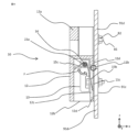
- FIG. 6 is a cross-sectional view taken along line AA of the pressure relief device according to Embodiment 1, showing a state in which the pressure relief plate is in the closed position.
- the deformation portion 11b is not deformed, and the pressure relief plate 11 as a whole has a flat plate shape extending in the vertical direction.
- the movable portion 11 c is in close contact with the pressure release device mounting portion 91 d to close the pressure release hole 91 c and the opening 12 c of the cover 12 . Due to the elastic force of the torsion coil spring 15, the pressing portion 15b applies a load F to the movable portion 11c so as to press it against the pressure release device mounting portion 91d, thereby holding the movable portion 11c in the closed position.
- the portions other than the opening 12c are fixed to the pressure release device mounting portion 91d without a gap, and are in close contact with the pressure release device mounting portion 91d.
- An opening 12b is provided at the bottom, and the lower end 12d of the cover 12 on the +x-axis direction side is also in close contact with the pressure release device mounting portion 91d. Therefore, the cover 12 seamlessly covers the outer circumference of the movable portion 11c in the closed position. Foreign matter entering the cover 12 through the opening 12b is prevented from entering the storage box 91 by the movable portion 11c in the closed position. Therefore, the cover 12 having the structure described above prevents foreign matter from entering the storage box 91 not only from the horizontal direction (x-axis direction and y-axis direction) and from above but also from below. be able to.
- FIG. 7 is a cross-sectional view taken along line AA of the pressure relief device according to Embodiment 1, showing a state in which the pressure relief plate is at the open position.
- the switch 100 housed in the storage box 91 performs a current interruption operation
- the pressure inside the storage box 91 rises.
- the increased pressure increases the load P on the movable portion 11 c of the pressure release plate 11 in the direction toward the outside of the storage box 91 .
- the load F is applied to the movable portion 11c mainly by the torsion coil spring 15.
- the load P exceeds the load F.
- the deformable portion 11b begins to elastically deform, and the movable portion 11c is separated from the pressure release device mounting portion 91d.
- the movable portion 11c is pushed by the load P and rotates around the y-axis with the deformation portion 11b as the center.
- the direction of rotation is the direction in which the movable portion 11c is lifted (the clockwise direction in FIG. 7).
- the movable portion 11c rotates until its lower end contacts the inner wall of the cover 12 and reaches the open position shown in FIG. Note that the holding portion 15b of the torsion coil spring 15 is also rotated by the rotation of the movable portion 11c.
- the “first pressure” is predetermined by the mass of the movable portion 11 c and the elastic force of the torsion coil spring 15 .
- the gas G in the storage box 91 flows out of the storage box 91 through the pressure relief hole 91c and the opening 12c. begin to be released.
- the pressure is released.
- the gas G released to the outside of the storage box 91 flows into the cover 12, but since the cover 12 covers the pressure release hole 91c without gaps, the gas G flows out of the cover 12 only through the opening 12b. released.
- the movable portion 11c When the movable portion 11c is in the open position, the movable portion 11c is subjected to a load P, a reaction force N (not shown) from the inner surface of the cover 12, a load F from the torsion coil spring 15, and an elastic force of the deformable portion 11b.
- a load FK (not shown in FIG. 7) and a gravity FG (not shown in FIG. 7) are applied.
- the load P acts to keep the movable portion 11c at the open position, and the reaction force N prevents further rotation of the movable portion 11c.
- the load F acts to return the movable portion 11c to the closed position as shown in FIG.
- the load FK also acts to restore the movable portion 11c to the closed position.
- Gravity FG also acts to return the movable portion 11c to the closed position.
- the movable portion 11c After returning to the closed position, the movable portion 11c is pressed against the pressure release device mounting portion 91d by the pressing portion 15b to close the pressure release hole 91c.
- the “second pressure” is determined in advance by the mass of the movable portion 11 c, the elastic force of the deformable portion 11 b, and the elastic force of the torsion coil spring 15 .
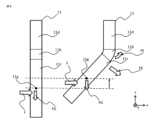
- FIG. 8 is a diagram for explaining the return operation of the pressure relief plate.
- FIG. 8 shows the pressure relief plate 11 in the closed position on the left side and the pressure relief plate 11 in the open position on the right side.
- the gravity FG acts on the center of gravity 11g of the movable portion 11c. has a component in the direction perpendicular to the side of
- the gravity FG is directed to return to the closed position (counterclockwise around the y-axis in FIG. 8) so that the movable portion 11c returns from the open position to the closed position and the center of gravity 11g returns to the closed position. to rotate the movable portion 11c.
- the deformable portion 11b is not deformed in the state of being in the closed position, and no elastic force is generated.
- the deformation portion 11b in the open position, the deformation portion 11b is elastically deformed so that the +x side expands and the ⁇ x side contracts, and an elastic force FE is generated in the deformation portion 11b so as to cancel this elastic deformation.
- a load FK acts on the movable portion 11c in the open position in the direction of returning to the closed position.
- the load F acts on the movable portion 11c in the direction of returning to the closed position from the torsion coil spring 15 (not shown in FIG. 8).
- the pressure release device 10 is configured to automatically return the movable portion 11c of the pressure release plate 11 from the open position to the closed position using the load F, the gravity FG, and the load FK.
- the pressure release plate 11 is made of a thin plate made of an elastically deformable resin material.
- the thickness of the pressure relief plate 11 is not limited, but the thinner it is, the lighter the pressure relief plate 11 is, and the less the load caused by the impact and vibration caused by the operation of the switch 100, the pressure relief plate 11 is held in the closed position.
- the load (closing load) for closing can be made smaller. When the closing load is smaller, a smaller torsion coil spring 15 can be used, and the size and weight of the pressure relief device 10 can be reduced.
- the elastic force of the deformable portion 11b and the gravitational force acting on the movable portion 11c are also reduced.
- the elastic force of the deformable portion 11b and the gravity acting on the movable portion 11c act to move the movable portion 11c to the closed position. easier to move to Therefore, when the current interrupting operation is performed by the switch 100 and the pressure inside the storage box 91 rises, the movable portion 11c moves to the open position in a shorter period of time. can be suppressed more. In this case, the required strength of the storage box 91 can be further reduced, and the structure of the storage box 91 can be simplified and the weight of the storage box 91 can be further reduced.
- the strength of the pressure relief plate 11 can be increased, although the effects such as weight reduction described above are not as good as when the pressure relief plate 11 is configured to be thin.
- the movable portion of the pressure relief plate of the first embodiment is configured to return from the open position to the closed position using only the elastic force of the pressure relief plate itself, the elastic force of the torsion coil spring, and gravity. Therefore, the movable part of the pressure relief plate can be realized simply and lightly. Since the pressure is released more quickly when the pressure release hole is more widely opened, the faster the movable portion moves from the closed position to the open position, the faster the pressure is released.
- the weight of the movable part is reduced as described above, considering the influence of gravity, the lighter the movable part, the faster the movement from the closed position to the open position is performed, and the quicker the pressure is released, the more quickly the storage box can be moved.
- the internal pressure rise can be suppressed more effectively. If the pressure rise in the storage box can be suppressed more effectively, the strength required for the storage box can be reduced. As a result, the structure of the storage box can be simplified and the weight of the storage box can be reduced.
- the top and sides of the pressure relief plate are covered with a cover, foreign matter is prevented from entering the storage box.
- the handle is integrated into the upper part of the cover, there is no need to separately provide a handle that serves as a handle when transporting the storage box, and the number of parts can be reduced.
- the winding portion is arranged so as to be sandwiched between the raised portion provided on the support and the movable portion of the pressure discharge plate, and the width of the gap between the raised portion and the shaft is the width of the winding that constitutes the winding portion.
- the winding portion is configured such that movement of the winding portion along the axial direction of the shaft is restricted by the rising portion.
- the cover covers the pressure release hole without gaps, the gas released to the outside of the storage box 91 during pressure release is released downward from the cover only through the opening at the lower end of the cover.
- the substance released together with the gas from the storage box is discharged only downward, it is possible to prevent the substance from scattering over a wide area, and to suppress the adverse effects of the substance on the peripheral equipment. can be done.
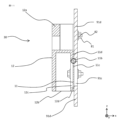
- FIG. 9 is a cross-sectional view taken along line AA of the pressure relief device according to Embodiment 2, showing a state in which the pressure relief plate is in the closed position.
- FIG. 10 is a diagram showing a state in which the pressure release plate is in the open position.
- Pressure-releasing device 20 is obtained by replacing pressure-releasing plate 11 of pressure-releasing device 10 in Embodiment 1 with pressure-releasing plate 21 shown in FIGS.
- the pressure release plate 21 has a plate-like portion and an arm (described later), and is made of a material that is difficult to elastically deform.
- the pressure-releasing plate 21 does not have a portion that is elastically deformed, and the entire plate-like portion of the pressure-releasing plate 21 serves as the movable portion 21c.
- the pressure relief plate 21 is made of, for example, a ferrous metal such as iron or stainless steel, a nonferrous metal such as aluminum or copper, or an insulating material (thermoplastic resin or thermosetting resin) such as epoxy resin or polyethylene resin. It has greater rigidity than the pressure relief plate 11 . Although the thickness of the pressure release plate 21 is not particularly limited, it is preferable to make it thinner from the viewpoint of weight reduction.
- the pressure release plate 21 is provided with an arm 27 at the upper end of the movable portion 21c.
- the arm 27 is made of metal, for example, and configured to stand up from the movable portion 21c.
- the arm 27 extends from the movable portion 21c in the ⁇ x-axis direction.
- the arm 27 is provided with a hole 27a into which the shaft 14 is fitted, and the arm 27 and the movable portion 21c are fixed to the shaft 14 which is fitted into the hole 27a. This configuration allows the movable portion 21 c to rotate together with the shaft 14 .
- a torsion coil spring 15 is attached to the shaft 14, and the load of the torsion coil spring 15 holds the movable portion 21c in the closed position as in the first embodiment. Also, the movable portion 21c moves from the closed position to the open position due to the increase in pressure inside the storage box 91 when the current is interrupted. Further, unlike the pressure release plate 11 of the first embodiment, although it is not affected by elastic deformation and elastic force, it is the same as the first embodiment in that it returns to the closed position after the pressure is released. When the load F and the gravity FG (not shown in FIGS. 9 and 10) due to the torsion coil spring 15 exceed the load P (not shown in FIGS. 9 and 10) due to the pressure inside the storage box 91, the load F and the gravity FG The pressure relief plate 21 in the open position returns to the closed position.
- the movable portion 21c has a cut portion 21f in which the corner of the upper end facing the storage box 91 is cut to remove the edge.
- the upper end of the movable portion 21c facing the storage box 91 is pressed against the pressure release device mounting portion 91d.
- the edge may interfere with the -x side surface of the pressure release device mounting portion 91d, hindering smooth movement from the closed position to the open position, but the cut portion 21f is formed.
- the cut portion 21f slides on the -x side surface of the pressure release device mounting portion 91d. Therefore, smooth movement of the movable portion 21c from the closed position to the open position is not hindered.
- Others are the same as those of the first embodiment, so description thereof will be omitted.
- the pressure release plate is made of a metal material or a resin material that has greater rigidity and hardly undergoes elastic deformation. Therefore, the flame retardancy and strength of the pressure relief plate can be further enhanced.
- FIG. 11 is a cross-sectional view taken along line AA of the pressure relief device according to Embodiment 3, showing a state in which the pressure relief plate is in the closed position.
- the pressure relief device 30 is the same as the pressure relief device 10 of the first embodiment, except that the torsion coil spring 15 is omitted. Further, along with the omission of the torsion coil spring 15, the shaft 14 and the support 13 are also omitted. As described above, since the deformation portion 11b has elasticity, the pressure release plate 11 alone can provide a certain degree of sealing performance.
- the elastic force of the deformable portion 11b applies a load to the movable portion 11c in the direction of holding it in the closed position.
- the elastic force of the deformation portion 11b applies a load to the movable portion 11c in the direction of returning to the closed position. That is, even without the load F of the torsion coil spring 15, the return operation from the open position to the closed position is realized by the load due to the elastic force of the deformation portion 11b and the gravity FG.
- Others are the same as those of the first embodiment, so description thereof will be omitted.
- Embodiment 4 will be described with reference to FIG. 1 to 12 are denoted by the same reference numerals, and description thereof will be omitted.
- 12 is a front view of a pressure relief device according to Embodiment 4.
- the pressure release device 40 is constructed by omitting the handle portion 12a from the cover 12 of the first embodiment as a cover 42. As shown in FIG. Others are the same as those of the first embodiment, so description thereof will be omitted.
- the handle is omitted from the cover, so the cover is downsized. Therefore, it is possible to reduce the size and weight of the pressure relief device.
Abstract
Obtained in the present invention are a storage box and an opening/closing device that make it possible to reduce the weight of the storage box while also preventing foreign matter from entering the storage box. A storage box (91) houses an opener/closer (100), and has a pressure release hole (91c) provided to a side wall for releasing internal pressure, and a pressure release device (10) attached to the (side wall 91c). The pressure release device (10) is provided with: a pressure release plate (11) comprising a movable part (11c) which is capable of moving between a sealed position for sealing the pressure release hole (91c) and an open position for opening the pressure release hole (91c); and a deformable part (11b) that is elastically deformable and deforms according to the movement of the movable part (11c). When the movable part (11c) is at the open position, a load is applied, due to the elastic force of the deformable part (11b), to the movable part (11c) in a direction of return to the sealed position.
Description
本願は、収納箱および開閉装置に関するものである。
This application relates to storage boxes and opening/closing devices.
開閉装置は、開閉器と、開閉器を収納し、開閉器が雨または塵埃などの異物に暴露されることを防ぐ保護箱などの収納箱を備える。この収納箱は、異物の内部への侵入を防ぐために高い密閉性を持つように構成される。一方、電流遮断時においてはアーク発弧により収納箱内部の圧力が上昇する可能性があるため、電流遮断時の圧力上昇を防ぐための放圧装置が収納箱に設けられる。放圧装置は、電流遮断時以外は収納箱の密閉性を維持しつつ、電流遮断時に収納箱内部の気体を外部に放出することにより、収納箱内部の急激な圧力上昇を防ぐように構成される。このような放圧装置を実現する構成として、収納箱に形成された放圧孔と、電流遮断時は放圧孔を開放するとともに、電流遮断時以外は放圧孔を密閉する放圧蓋とを備えた放圧構造が開示されている(例えば、特許文献1参考)。特許文献1の放圧構造では、放圧孔の周辺にOリング取付部材を設けて凸状に形成し、放圧蓋は、Oリング取付部材も含めて放圧孔を覆うように凹状に構成されている。放圧蓋は、ねじりコイルばねの弾性力と電流遮断時の内圧上昇の関係を利用し、開放位置と密閉位置を推移する。さらに放圧蓋には、その位置を密閉位置に保持するための被係止部材が設けられている。放圧蓋は、放圧孔に設けられた係止部材に上記被係止部材を係止させることにより密閉位置に保持され、収納箱内への異物の侵入を防ぐことができる。
A switchgear includes a switch and a storage box such as a protective box that stores the switch and prevents the switch from being exposed to foreign matter such as rain or dust. This storage box is configured to have a high airtightness in order to prevent foreign matter from entering the interior. On the other hand, since there is a possibility that the pressure inside the storage box will increase due to arcing when the current is interrupted, the storage box is provided with a pressure release device for preventing the pressure increase when the current is interrupted. The pressure relief device is configured to prevent a sudden increase in pressure inside the storage box by releasing the gas inside the storage box to the outside when the current is interrupted while maintaining the sealability of the storage box except when the current is interrupted. be. As a configuration for realizing such a pressure release device, a pressure release hole formed in the storage box and a pressure release lid that opens the pressure release hole when the current is interrupted and seals the pressure release hole when the current is not interrupted. is disclosed (see, for example, Patent Document 1). In the pressure release structure of Patent Document 1, an O-ring mounting member is provided around the pressure-releasing hole to form a convex shape, and the pressure-releasing lid is formed in a concave shape so as to cover the pressure-releasing hole, including the O-ring mounting member. It is The pressure-releasing lid utilizes the relationship between the elastic force of the torsion coil spring and the increase in internal pressure when the current is interrupted, and transitions between the open position and the closed position. Further, the pressure release lid is provided with a locked member for holding the position in the closed position. The pressure-releasing lid is held in a closed position by locking the member to be locked with a locking member provided in the pressure-releasing hole, and foreign matter can be prevented from entering the storage box.
特許文献1の放圧構造では、凹状の形状および被係止部材の取り付けにより、簡単な板状部材のみで構成される放圧板と比べて放圧蓋の質量が増加している。このため、放圧蓋にはより大きな重力が働く。放圧蓋に働く重力は、放圧蓋の密閉位置から開放位置への移動を遅らせる方向に作用するため、特許文献1における放圧蓋は、電流遮断時における密閉位置から開放位置への移動により長い時間を要する。電流遮断から放圧までの時間が長期化する場合、その間の圧力上昇に備えるため、収納箱の強度を増加させる必要があるが、強度増加は収納箱の構造の複雑化および収納箱の重量化を招いてしまう。
In the pressure-releasing structure of Patent Document 1, the mass of the pressure-releasing lid is increased due to the recessed shape and attachment of the engaged member compared to the pressure-releasing plate composed only of a simple plate-like member. For this reason, a larger gravity acts on the pressure release lid. Gravity acting on the pressure-releasing lid acts in a direction that delays the movement of the pressure-releasing lid from the closed position to the open position. takes a long time. If the time from current interruption to pressure release is long, it is necessary to increase the strength of the storage box in order to prepare for the pressure rise during that time. invites
本願は、上記のような課題を解決するための技術を開示するものであり、収納箱内への異物の侵入を防ぎつつ、収納箱の軽量化を図ることができる収納箱および開閉装置を得ることを目的とする。
The present application discloses a technique for solving the above-described problems, and provides a storage box and an opening/closing device capable of reducing the weight of the storage box while preventing foreign matter from entering the storage box. The purpose is to
本願に開示される収納箱は、開閉器を収納し、内部の圧力を放圧する放圧孔が側壁に設けられ、側壁には開閉器の放圧装置が取り付けられた収納箱であって、開閉器の放圧装置は、放圧孔を密閉する密閉位置と放圧孔を開放する開放位置との間を移動可能な可動部と、弾性変形可能であり、可動部の移動に合わせて変形する変形部とを有する放圧板を備え、変形部の弾性力は、可動部が開放位置にあるときに、密閉位置に復帰する方向に可動部に荷重を加えるものである。
The storage box disclosed in the present application is a storage box in which a switch is housed, a pressure release hole is provided in the side wall for releasing the internal pressure, and a pressure release device for the switch is attached to the side wall. The pressure release device of the container includes a movable part that can move between a closed position that seals the pressure release hole and an open position that opens the pressure release hole, and an elastically deformable part that deforms according to the movement of the movable part. The elastic force of the deformation portion applies a load to the movable portion in the direction of returning to the closed position when the movable portion is in the open position.
また、本願に開示される収納箱の別の形態は、開閉器を収納し、内部の圧力を放圧する放圧孔が側壁に設けられ、側壁には開閉器の放圧装置が取り付けられた収納箱であって、開閉器の放圧装置は、一端を中心軸として回動し、放圧孔を密閉する密閉位置と放圧孔を開放する開放位置との間を移動可能な可動部を有する放圧板と、中心軸の方向の両側において側壁に固定される支持体と、支持体に設けられた貫通孔を貫通して支持体に支持されるシャフトと、シャフトに固定され、可動部が密閉位置にあるときは密閉位置に保持する方向に可動部に荷重を加え、可動部が開放位置にあるときは密閉位置に復帰する方向に可動部に荷重を加えるねじりコイルばねとを備え、放圧板は、平板形状の板状部と、板状部の一端に設けられ、シャフトが篏合する孔が設けられたアームとを有し、シャフトとともに全体が回動するものである。
Further, another form of the storage box disclosed in the present application is a storage box in which a switch is stored, a pressure release hole for releasing the internal pressure is provided in the side wall, and a pressure release device for the switch is attached to the side wall. The box, the pressure release device of the switch, has a movable part that rotates around one end as a central axis and can move between a closed position that seals the pressure release hole and an open position that opens the pressure release hole. A pressure release plate, a support fixed to the side wall on both sides in the direction of the central axis, a shaft penetrating through a through hole provided in the support and supported by the support, fixed to the shaft, and the movable part is sealed. a torsion coil spring that applies a load to the movable part in a direction to hold it in the closed position when it is in the open position, and a torsion coil spring that applies a load to the movable part in a direction to return to the closed position when the movable part is in the open position; has a flat plate-like portion and an arm provided at one end of the plate-like portion and provided with a hole into which a shaft is fitted, and rotates with the shaft as a whole.
本願に開示される収納箱によれば、収納箱内への異物の侵入を防ぎつつ、収納箱の軽量化を図ることができる。
According to the storage box disclosed in the present application, it is possible to reduce the weight of the storage box while preventing foreign matter from entering the storage box.
実施の形態1.
実施の形態1を図1から図8に基づいて説明する。図1は、実施の形態1における開閉装置の斜視図である。開閉装置1000は、例えば電力用の開閉器100と、この開閉器を収納している保護箱などの収納箱91とを備えている。収納箱91は、例えば上下2段の箱体であり、内部への異物の混入を防ぐように、高い密閉性を有する構成を持つ。なお、以下では説明のために、下記のように座標軸を設定する。すなわち、鉛直方向をz軸とし、z軸と直交する方向、すなわち水平方向にx軸およびy軸を設定する。収納箱91の長辺方向に沿う方向にx軸を設定し、収納箱91の短辺方向に沿う方向にy軸を設定する。またz軸について、上方向を+z軸方向、下方向を-z軸方向とする。x軸およびy軸については、図1に示すように一方を+x軸方向および+y軸方向とし、その反対方向を-x軸方向および-y軸方向正方向とする。収納箱の上部91Aは、上面側が狭くなるように台形の断面を持つ。ただし、収納箱91の形状は、図1に示すものに限定されない。 Embodiment 1.
Embodiment 1 will be described with reference to FIGS. 1 to 8. FIG. FIG. 1 is a perspective view of an opening/closing device according to Embodiment 1. FIG. Theswitchgear 1000 includes, for example, a power switch 100 and a storage box 91 such as a protection box that stores the switch. The storage box 91 is, for example, a two-tiered box body, and has a highly airtight structure so as to prevent foreign matter from entering the inside. For the sake of explanation, coordinate axes are set as follows. That is, the vertical direction is the z-axis, and the x-axis and the y-axis are set in a direction perpendicular to the z-axis, that is, in the horizontal direction. The x-axis is set along the long side direction of the storage box 91 , and the y-axis is set along the short side direction of the storage box 91 . Regarding the z-axis, the upward direction is the +z-axis direction, and the downward direction is the -z-axis direction. As for the x-axis and the y-axis, as shown in FIG. 1, one side is the +x-axis direction and the +y-axis direction, and the opposite direction is the -x-axis direction and the -y-axis direction positive direction. The upper part 91A of the storage box has a trapezoidal cross section so that the top side is narrower. However, the shape of the storage box 91 is not limited to that shown in FIG.
実施の形態1を図1から図8に基づいて説明する。図1は、実施の形態1における開閉装置の斜視図である。開閉装置1000は、例えば電力用の開閉器100と、この開閉器を収納している保護箱などの収納箱91とを備えている。収納箱91は、例えば上下2段の箱体であり、内部への異物の混入を防ぐように、高い密閉性を有する構成を持つ。なお、以下では説明のために、下記のように座標軸を設定する。すなわち、鉛直方向をz軸とし、z軸と直交する方向、すなわち水平方向にx軸およびy軸を設定する。収納箱91の長辺方向に沿う方向にx軸を設定し、収納箱91の短辺方向に沿う方向にy軸を設定する。またz軸について、上方向を+z軸方向、下方向を-z軸方向とする。x軸およびy軸については、図1に示すように一方を+x軸方向および+y軸方向とし、その反対方向を-x軸方向および-y軸方向正方向とする。収納箱の上部91Aは、上面側が狭くなるように台形の断面を持つ。ただし、収納箱91の形状は、図1に示すものに限定されない。 Embodiment 1.
Embodiment 1 will be described with reference to FIGS. 1 to 8. FIG. FIG. 1 is a perspective view of an opening/closing device according to Embodiment 1. FIG. The
上部91Aにおいて、短辺方向(y軸方向)に沿う側壁91Aaの外側面には、放圧装置10Aおよび10B、すなわち開閉器の放圧装置が取り付けられる。図1には記載されていないが、側壁91Aaにおいて放圧装置が取り付けられる位置には放圧孔が設けられる。図1では、両側の側壁91Aaに1つずつ、2つ1組で放圧装置を取り付けているが、取り付ける放圧装置の数および取付け位置は特に限定されない。収納箱91の長辺方向(x軸方向)に沿う側壁91Abに放圧装置10を取り付けてもよい。下部91Bにおいて、長辺方向(x軸方向)に沿う側壁91Bbには、母線92が貫通する孔(図示無し)が設けられている。
以降の説明では、放圧装置10Aを例に説明する。 Pressure relief devices 10A and 10B, ie, switch pressure relief devices, are attached to the outer side surfaces of side walls 91Aa along the short side direction (y-axis direction) of the upper portion 91A. Although not shown in FIG. 1, a pressure release hole is provided in the side wall 91Aa at a position where the pressure release device is attached. In FIG. 1, two pressure release devices are attached to each side wall 91Aa on both sides, but the number and attachment positions of the pressure release devices to be attached are not particularly limited. The pressure release device 10 may be attached to the side wall 91Ab along the long side direction (x-axis direction) of the storage box 91 . In the lower portion 91B, a side wall 91Bb along the long side direction (x-axis direction) is provided with a hole (not shown) through which the busbar 92 passes.
In the following description, thepressure release device 10A will be described as an example.
以降の説明では、放圧装置10Aを例に説明する。
In the following description, the
図2は、実施の形態1における放圧装置の正面図であり、図1の+x軸方向に放圧装置10Aを見た場合の図である。なお、放圧装置10Bについても同様であるので、以降では単に放圧装置10として説明する。
FIG. 2 is a front view of the pressure relief device according to Embodiment 1, and is a diagram when the pressure relief device 10A is viewed in the +x-axis direction of FIG. Since the same applies to the pressure relief device 10B, it will be simply referred to as the pressure relief device 10 hereinafter.
放圧装置10は、側壁91Aaの予め定められた位置に設けられた放圧装置取付け部91dに取り付けられる。放圧装置取付け部91dの位置および範囲は、側壁91Aaに形成された放圧孔91cを含み、放圧装置10の取付けに必要なねじ穴などを形成可能であれば特に限定されない。放圧装置10は、放圧孔91cを覆う放圧板11と、放圧板11を覆うカバー12と、放圧板11の可動部11cのy軸方向両側に配置された2つの板状部材を含んで構成され、放圧装置取付け部91dに固定された支持体13と、支持体13に設けられた貫通孔13aaを貫通するシャフト14と、シャフト14に取り付けられたダブルトーション形状のねじりコイルばね15とを備えている。なお、図2では円形の孔を2個隣接して設けたものを放圧孔91cとしているが、放圧孔91cの形状および数はこの限りではなく、任意に設ける事ができる。
The pressure relief device 10 is attached to a pressure relief device attachment portion 91d provided at a predetermined position on the side wall 91Aa. The position and range of the pressure release device mounting portion 91d are not particularly limited as long as the pressure release hole 91c formed in the side wall 91Aa and a screw hole required for mounting the pressure release device 10 can be formed. The pressure-releasing device 10 includes a pressure-releasing plate 11 covering the pressure-releasing hole 91c, a cover 12 covering the pressure-releasing plate 11, and two plate-like members arranged on both sides of the movable portion 11c of the pressure-releasing plate 11 in the y-axis direction. A support 13 fixed to a pressure release device mounting portion 91d, a shaft 14 passing through a through hole 13aa provided in the support 13, and a double torsion-shaped torsion coil spring 15 attached to the shaft 14. It has In FIG. 2, two adjacent circular holes are used as the pressure release holes 91c.
放圧板11はカバー12と同様の外形を有し、カバー12とともに放圧装置取付け部91dに取り付けられた際に、カバー12と放圧装置取付け部91dとの間に隙間が生じることを防ぐ構成となっている。また、放圧板11にはU字スリット11aが設けられており、U字スリット11aに囲まれた範囲には、移動可能な可動部11cが設けられている。可動部11cは、側壁91Aaに密着して放圧孔91cを密閉する密閉位置と、側壁91Aaから離間して放圧孔91cを開放する開放位置との間を移動するもので、通常時は密閉位置にある。このため、可動部11cの位置および範囲は、少なくとも放圧孔91cを密閉可能に構成する必要がある。放圧板11のより詳細な構成については後述する。
The pressure relief plate 11 has the same outer shape as the cover 12, and is configured to prevent a gap from occurring between the cover 12 and the pressure relief device attachment portion 91d when the pressure relief plate 11 is attached to the pressure relief device attachment portion 91d together with the cover 12. It has become. A U-shaped slit 11a is provided in the pressure release plate 11, and a movable portion 11c is provided in a range surrounded by the U-shaped slit 11a. The movable portion 11c moves between a closed position in which the pressure release hole 91c is closed by closely contacting the side wall 91Aa and an open position in which the pressure release hole 91c is opened by separating from the side wall 91Aa. in position. Therefore, the position and range of the movable portion 11c must be configured so that at least the pressure release hole 91c can be sealed. A more detailed configuration of the pressure relief plate 11 will be described later.
カバー12は、放圧装置取付け部91dに取り付けられる。図2では図示省略しているが、カバー12は、可動部11cに対応させて開口部が設けられている。また、カバー12の上部には把持可能なハンドル部12aが一体に設けられている。ハンドル部12aは、カバー12の上部のy軸方向両側端部を上方に突出させ、両側の突出部を連結することで構成される。
The cover 12 is attached to the pressure release device attachment portion 91d. Although not shown in FIG. 2, the cover 12 has an opening corresponding to the movable portion 11c. Moreover, a grippable handle portion 12 a is integrally provided on the upper portion of the cover 12 . The handle portion 12a is configured by projecting both ends in the y-axis direction of the upper portion of the cover 12 upward and connecting the projecting portions on both sides.
支持体13は、ボルトおよびナット等の締結部材により、収納箱91に対して放圧板11およびカバー12と一体に固定される。シャフト14は、貫通孔13aaを貫通することで支持体13に回動可能に支持される。またシャフト14は、軸方向の両端がカバー12の内壁と干渉することで軸方向の変位が制限されており、貫通孔13aaからの脱落が防がれている。ねじりコイルばね15は、ねじりコイルばね15の弾性力による荷重を放圧板11の可動部11cに加える押さえ部15bを有している。
The support 13 is integrally fixed to the storage box 91 with the pressure relief plate 11 and the cover 12 by fastening members such as bolts and nuts. The shaft 14 is rotatably supported by the support 13 by passing through the through hole 13aa. Further, axial displacement of the shaft 14 is restricted by interference with the inner wall of the cover 12 at both ends in the axial direction, so that the shaft 14 is prevented from falling out of the through hole 13aa. The torsion coil spring 15 has a pressing portion 15 b that applies the load due to the elastic force of the torsion coil spring 15 to the movable portion 11 c of the pressure release plate 11 .
図3は、実施の形態1における放圧装置の部品展開図であり、図3中の一点鎖線は締結部材であるボルト81とナット82の組立位置を示すものである。図3に示すように、放圧装置取付け部91dの予め定められた位置には、ボルト81が挿入される孔91eが設けられている。放圧装置10は、以下のようにして収納箱91(放圧装置取付け部91d)に取り付けられる。まず、図3に示すように、ねじりコイルばね15およびシャフト14を取り付けた状態の支持体13をカバー12の下端に設けられた開口部12bからカバー12の内部に挿入して1つの部品とする。次に、上記部品(カバー12、支持体13、シャフト14、およびねじりコイルばね15)と放圧装置取付け部91dとの間に挟むように放圧板11を配置し、ボルト81およびナット82を用いて上記部品と放圧板11とを締結固定することにより、各部品を放圧装置取付け部91dに取り付ける。この際、カバー12の開口部12cと放圧板11の可動部11cの位置を合わせる。また、放圧装置取付け部91d側のカバー12の側面は、開口部12cを除いて放圧装置取付け部91dに密着させる。
FIG. 3 is an exploded view of the parts of the pressure relief device according to Embodiment 1, and the dashed-dotted line in FIG. As shown in FIG. 3, a hole 91e into which the bolt 81 is inserted is provided at a predetermined position of the pressure release device mounting portion 91d. The pressure relief device 10 is attached to the storage box 91 (pressure relief device attachment portion 91d) as follows. First, as shown in FIG. 3, the support 13 with the torsion coil spring 15 and the shaft 14 attached thereto is inserted into the cover 12 through the opening 12b provided at the lower end of the cover 12 to form one component. . Next, the pressure relief plate 11 is arranged so as to be sandwiched between the components (cover 12, support 13, shaft 14, and torsion coil spring 15) and the pressure relief device mounting portion 91d, and bolts 81 and nuts 82 are used to secure the pressure relief plate 11. Each component is attached to the pressure relief device mounting portion 91d by fastening and fixing the above components and the pressure relief plate 11 with a screw. At this time, the opening 12c of the cover 12 and the movable portion 11c of the pressure release plate 11 are aligned. In addition, the side surface of the cover 12 on the side of the pressure release device mounting portion 91d is brought into close contact with the pressure release device mounting portion 91d except for the opening 12c.
なお、放圧装置取付け部91dに取り付けられるそれぞれの部品においても、孔91eに対応する位置にボルト81を挿入するための孔が設けられている。また、実施の形態1ではボルト81およびナット82といった締結部材を用いて放圧装置10を放圧装置取付け部91dに取り付けているが、リベット等、他の固定部材を用いる取付け方法を用いてもよい。
Each component attached to the pressure release device attachment portion 91d is also provided with a hole for inserting the bolt 81 at a position corresponding to the hole 91e. Further, in Embodiment 1, the pressure relief device 10 is attached to the pressure relief device mounting portion 91d using the fastening members such as the bolts 81 and the nuts 82, but a mounting method using other fixing members such as rivets may also be used. good.
次に、放圧板11のより詳細な構成について説明する。図4Aは、実施の形態1に係る放圧板の正面図であり、図1の+x軸方向に放圧板11を見た場合の図である。上述したように、放圧板11はカバー12と同様の外形を持ち、上部が一部窪んだような外形を持つ。放圧板11の上下方向中心部にはU字スリット11aが設けられており、U字スリット11aに囲まれる範囲に可動部11cが設けられる。可動部11cの上端、U字スリット11aの開口部分には、y軸方向に延び、弾性変形可能な変形部11bが設けられている。可動部11cは、変形部11bが弾性変形することにより、変形部11bを中心としてy軸回りに回動する。これにより、可動部11cはヒンジ状に開閉運動し、可動部11cは密閉位置と開放位置との間を移動可能となっている。放圧板11のうち、U字スリット11aで囲まれる範囲以外の領域は固定部11dとなっている。固定部11dにはボルト81が挿入される孔11eが形成されており、ボルト81およびナット82により放圧装置取付け部91dに固定される。孔11eの位置および数は、放圧装置取付け部91dの孔91eの位置および数に対応している。
Next, a more detailed configuration of the pressure relief plate 11 will be described. FIG. 4A is a front view of the pressure-releasing plate according to Embodiment 1, and is a view when the pressure-releasing plate 11 is seen in the +x-axis direction of FIG. As described above, the pressure release plate 11 has an outer shape similar to that of the cover 12, and has an outer shape such that the upper portion is partially recessed. A U-shaped slit 11a is provided in the vertical central portion of the pressure release plate 11, and a movable portion 11c is provided in a range surrounded by the U-shaped slit 11a. A deformable portion 11b that extends in the y-axis direction and is elastically deformable is provided at the upper end of the movable portion 11c, at the opening of the U-shaped slit 11a. The movable portion 11c rotates about the y-axis centering on the deformable portion 11b due to elastic deformation of the deformable portion 11b. As a result, the movable portion 11c opens and closes like a hinge, and the movable portion 11c can move between the closed position and the opened position. An area of the pressure release plate 11 other than the area surrounded by the U-shaped slit 11a serves as a fixing portion 11d. A hole 11e into which a bolt 81 is inserted is formed in the fixed portion 11d, and is fixed to the pressure release device mounting portion 91d by a bolt 81 and a nut 82. As shown in FIG. The position and number of the holes 11e correspond to the positions and number of the holes 91e of the pressure release device mounting portion 91d.
図4Bは、実施の形態1に係る放圧板の他の例を示す正面図である。図4Bに示す例では、U字スリット11aが形成されていない。放圧板111は、y軸方向に延び、弾性変形可能な変形部111bがz軸方向の中央部に設けられている。変形部111bは、y軸方向について放圧板111の両端に亘って形成されており、変形部111bよりも上部が固定部111d、変形部111bよりも下部が可動部111cとなっている。可動部111cは、変形部111bが弾性変形することにより、変形部111bを中心としてy軸回りに回動する。これにより、可動部111cはヒンジ状に開閉運動し、可動部111cは密閉位置と開放位置との間を移動可能となっている。固定部111dにはボルト81が挿入される孔11eが形成されており、ボルト81およびナット82により放圧装置取付け部91dに固定される。
FIG. 4B is a front view showing another example of the pressure relief plate according to Embodiment 1. FIG. In the example shown in FIG. 4B, the U-shaped slit 11a is not formed. The pressure release plate 111 extends in the y-axis direction and has an elastically deformable deformable portion 111b at the center in the z-axis direction. The deformable portion 111b is formed across both ends of the pressure release plate 111 in the y-axis direction, with a fixed portion 111d above the deformable portion 111b and a movable portion 111c below the deformable portion 111b. The movable portion 111c rotates about the y-axis around the deformable portion 111b due to elastic deformation of the deformable portion 111b. As a result, the movable portion 111c opens and closes like a hinge, and the movable portion 111c can move between the closed position and the opened position. A hole 11e into which a bolt 81 is inserted is formed in the fixed portion 111d, and is fixed to the pressure release device mounting portion 91d by a bolt 81 and a nut 82. As shown in FIG.
図4Cは、実施の形態1に係る放圧板の他の例を示す正面図である。放圧板112は、互いに対向する部位において、放圧板112のz軸方向の中央部から下端に延びる2つの直線スリット11f1および直線スリット11f2を形成し、変形部112bは、放圧板112のz軸方向の中央部において、直線スリット11f1と直線スリット11f2との間でy軸方向に延びている。放圧板112においては、直線スリット11f1と直線スリット11f2との間に可動部112cが形成され、それ以外の部分、すなわち、変形部112bよりも上部と、変形部112bよりも下部だが、直線スリット11f1と直線スリット11f2よりもy軸方向について端側に固定部112dが形成されている。可動部112cはヒンジ状に開閉運動し、可動部112cは密閉位置と開放位置との間を移動可能となっている。固定部112dにはボルト81が挿入される孔11eが形成されており、ボルト81およびナット82により放圧装置取付け部91dに固定される。直線スリット11f1および直線スリット11f2は、それぞれ第1のスリット部および第2のスリット部に相当する。このように、互いに対向する部位に2つのスリットを有し、これら2つのスリットに挟まれた領域が可動部となるように放圧板を構成してもよい。
FIG. 4C is a front view showing another example of the pressure relief plate according to Embodiment 1. FIG. The pressure-releasing plate 112 has two linear slits 11f1 and 11f2 extending from the central portion of the pressure-releasing plate 112 in the z-axis direction to the lower end at portions facing each other. extends in the y-axis direction between the linear slit 11f1 and the linear slit 11f2. In the pressure release plate 112, a movable portion 112c is formed between the linear slit 11f1 and the linear slit 11f2. A fixed portion 112d is formed on the end side in the y-axis direction from the linear slit 11f2. The movable portion 112c opens and closes like a hinge, and the movable portion 112c can move between a closed position and an open position. A hole 11e into which a bolt 81 is inserted is formed in the fixed portion 112d, and is fixed to the pressure release device mounting portion 91d by a bolt 81 and a nut 82. As shown in FIG. The linear slit 11f1 and the linear slit 11f2 correspond to the first slit portion and the second slit portion, respectively. In this manner, the pressure release plate may be configured to have two slits in mutually opposing portions, and the area sandwiched between these two slits may be the movable portion.
図5は、実施の形態1に係るねじりコイルばねの固定方法を説明する斜視図である。なお、図5に示している座標軸は、放圧装置10が収納箱91に取り付けられた状態における方向を示している。支持体13は、2つの板状の部材をそれぞれL字状に折り曲げて構成したもので、放圧板11の可動部11cのy軸方向両側に固定される。支持体13は、y軸方向と直交し、シャフト14が貫通する貫通孔13aaが設けられた側部13aと、側部13aと直交(x軸方向と直交)し、ボルト81が挿入される孔(図示無し)が設けられた底部13bと、底部13bのうち、内側(可動部11cに近い側)の一部を-x軸方向、すなわちシャフト14の側に立ち上げた立ち上げ部13cとを備えている。立ち上げ部13cとシャフト14との間には隙間を設ける。この隙間の幅は、ねじりコイルばね15の巻線部15aを構成する巻き線の太さよりも小さくなるように構成する。また立ち上げ部13cには、孔13caが設けられている。両側の支持体13の側部13aに設けられた貫通孔13aaは互いに対向している。シャフト14は、y軸方向に沿って延び、両側の貫通孔13aaを貫通することで両側の支持体13により支持されている。なお、支持体13は可動部11cのy軸方向両側でシャフト14を支持する構成であればよいので、板状のものに限定されない。例えば、シャフト14が貫通する孔が設けられ、放圧装置取付け部91dに固定された箱体であってもよい。
FIG. 5 is a perspective view explaining a fixing method of the torsion coil spring according to Embodiment 1. FIG. The coordinate axes shown in FIG. 5 indicate directions when the pressure release device 10 is attached to the storage box 91 . The support 13 is formed by bending two plate-like members into an L shape, and is fixed to both sides of the movable portion 11c of the pressure release plate 11 in the y-axis direction. The support body 13 has a side portion 13a which is orthogonal to the y-axis direction and provided with a through hole 13aa through which the shaft 14 penetrates, and a hole which is orthogonal to the side portion 13a (perpendicular to the x-axis direction) and into which the bolt 81 is inserted. (not shown) provided, and a raised portion 13c in which part of the inner side (closer to the movable portion 11c) of the bottom portion 13b is raised in the -x-axis direction, that is, on the shaft 14 side. I have. A gap is provided between the rising portion 13 c and the shaft 14 . The width of this gap is configured to be smaller than the thickness of the windings forming the winding portion 15 a of the torsion coil spring 15 . A hole 13ca is provided in the raised portion 13c. The through holes 13aa provided in the side portions 13a of the supports 13 on both sides face each other. The shaft 14 extends along the y-axis direction and is supported by the supports 13 on both sides by passing through the through holes 13aa on both sides. Note that the supporting member 13 is not limited to a plate-like member as long as it supports the shaft 14 on both sides of the movable portion 11c in the y-axis direction. For example, it may be a box body provided with a hole through which the shaft 14 penetrates and fixed to the pressure release device mounting portion 91d.
ねじりコイルばね15は、上述したようにダブルトーション形状を有し、2つの巻線部15aにシャフト14が貫通することでシャフト14に固定されている。巻線部15aは、立ち上げ部13cよりも内側、すなわち、可動部11cと立ち上げ部13cとの間に配置する。上述したように、立ち上げ部13cとシャフト14との間の隙間の幅は、巻線部15aを構成する巻き線の太さよりも小さいため、巻線部15aは、シャフト14の軸方向に沿った移動が立ち上げ部13cにより制限される構成となっている。また巻線部15aは、一方の端部が-z軸方向(下方向)に延びており、両側の巻線部15aによってコ字状の押さえ部15bを形成している。換言すると、コ字状に形成された押さえ部15bが、2つの巻線部のそれぞれの一端に接続されている。押さえ部15bは、ねじりコイルばね15の作用点となる。巻線部15aの他方の端部15cは、立ち上げ部13cの孔13caを貫通し、孔13caと係合している。これにより、端部15cはねじりコイルばね15の固定端となっている。
The torsion coil spring 15 has a double torsion shape as described above, and is fixed to the shaft 14 by penetrating the shaft 14 through the two winding portions 15a. The winding portion 15a is arranged inside the rising portion 13c, that is, between the movable portion 11c and the rising portion 13c. As described above, the width of the gap between the raised portion 13c and the shaft 14 is smaller than the thickness of the winding wire that constitutes the winding portion 15a. The movement is restricted by the raised portion 13c. One end of the winding portion 15a extends in the -z-axis direction (downward), and the winding portions 15a on both sides form a U-shaped pressing portion 15b. In other words, the U-shaped pressing portion 15b is connected to one end of each of the two winding portions. The pressing portion 15 b serves as an action point of the torsion coil spring 15 . The other end 15c of the winding portion 15a passes through the hole 13ca of the raised portion 13c and engages with the hole 13ca. As a result, the end portion 15 c serves as a fixed end of the torsion coil spring 15 .
図6は、実施の形態1における放圧装置のA-A断面図であり、放圧板が密閉位置にある状態を示す図である。図6に示すように、放圧板11が密閉位置にある状態では変形部11bは変形しておらず、放圧板11全体が上下方向に延びる平板状をなす。可動部11cは、放圧装置取付け部91dに密着し、放圧孔91c、およびカバー12の開口部12cを閉塞している。押さえ部15bは、ねじりコイルばね15の弾性力により、放圧装置取付け部91dに押し付けるように可動部11cに荷重Fを加え、可動部11cを密閉位置に保持している。
FIG. 6 is a cross-sectional view taken along line AA of the pressure relief device according to Embodiment 1, showing a state in which the pressure relief plate is in the closed position. As shown in FIG. 6, when the pressure relief plate 11 is in the closed position, the deformation portion 11b is not deformed, and the pressure relief plate 11 as a whole has a flat plate shape extending in the vertical direction. The movable portion 11 c is in close contact with the pressure release device mounting portion 91 d to close the pressure release hole 91 c and the opening 12 c of the cover 12 . Due to the elastic force of the torsion coil spring 15, the pressing portion 15b applies a load F to the movable portion 11c so as to press it against the pressure release device mounting portion 91d, thereby holding the movable portion 11c in the closed position.
なお、カバー12の+x軸方向側(収納箱91側)の側壁において、開口部12c以外の箇所は、放圧装置取付け部91dと隙間なく固定され、放圧装置取付け部91dと密着ている。下方には開口部12bが設けられているが、カバー12の+x軸方向側の下端部12dも放圧装置取付け部91dに密着している。このため、カバー12は、密閉位置にある可動部11cの外周を切れ目なく覆っている。開口部12bからカバー12内に侵入した異物は、密閉位置にある可動部11cにより収納箱91内への侵入が防がれる。このため、上記のような構造を持つカバー12により、水平方向(x軸方向およびy軸方向)および上方向からだけでなく下方向からについても、収納箱91内への異物の侵入を防止することができる。
In addition, on the side wall of the cover 12 on the +x-axis direction side (on the side of the storage box 91), the portions other than the opening 12c are fixed to the pressure release device mounting portion 91d without a gap, and are in close contact with the pressure release device mounting portion 91d. An opening 12b is provided at the bottom, and the lower end 12d of the cover 12 on the +x-axis direction side is also in close contact with the pressure release device mounting portion 91d. Therefore, the cover 12 seamlessly covers the outer circumference of the movable portion 11c in the closed position. Foreign matter entering the cover 12 through the opening 12b is prevented from entering the storage box 91 by the movable portion 11c in the closed position. Therefore, the cover 12 having the structure described above prevents foreign matter from entering the storage box 91 not only from the horizontal direction (x-axis direction and y-axis direction) and from above but also from below. be able to.
放圧装置10による放圧動作について説明する。図7は、実施の形態1における放圧装置のA-A断面図であり、放圧板が開放位置にある状態を示す図である。収納箱91に収納されている開閉器100が電流遮断動作を行うと、収納箱91内の圧力が上昇する。図7に示すように、上昇した圧力は、放圧板11の可動部11cに対し、収納箱91の外側に向かう方向に荷重Pを増大させる。上述したように、可動部11cには主にねじりコイルばね15により荷重Fが加えられているが、収納箱91内の圧力が上昇して第1の圧力を上回ると荷重Pが荷重Fを上回り、変形部11bが弾性変形を始めて可動部11cが放圧装置取付け部91dから離間する。可動部11cは荷重Pに押され、変形部11bを中心としてy軸回りに回動する。回動の方向は、可動部11cが持ち上がる方向(図7では時計回りの方向)である。可動部11cは、その下端がカバー12の内壁に当接するまで回動し、図7に示す開放位置に達する。なお、上記した可動部11cの回動により、ねじりコイルばね15の押さえ部15bも回動する。可動部11cが開放位置に達したとき、押さえ部15bの下端および端部15cの下端もカバー12の内側面に当接する。なお、「第1の圧力」は、可動部11cの質量およびねじりコイルばね15の弾性力により予め定められる。
The pressure release operation by the pressure release device 10 will be described. FIG. 7 is a cross-sectional view taken along line AA of the pressure relief device according to Embodiment 1, showing a state in which the pressure relief plate is at the open position. When the switch 100 housed in the storage box 91 performs a current interruption operation, the pressure inside the storage box 91 rises. As shown in FIG. 7 , the increased pressure increases the load P on the movable portion 11 c of the pressure release plate 11 in the direction toward the outside of the storage box 91 . As described above, the load F is applied to the movable portion 11c mainly by the torsion coil spring 15. However, when the pressure inside the storage box 91 rises and exceeds the first pressure, the load P exceeds the load F. , the deformable portion 11b begins to elastically deform, and the movable portion 11c is separated from the pressure release device mounting portion 91d. The movable portion 11c is pushed by the load P and rotates around the y-axis with the deformation portion 11b as the center. The direction of rotation is the direction in which the movable portion 11c is lifted (the clockwise direction in FIG. 7). The movable portion 11c rotates until its lower end contacts the inner wall of the cover 12 and reaches the open position shown in FIG. Note that the holding portion 15b of the torsion coil spring 15 is also rotated by the rotation of the movable portion 11c. When the movable portion 11c reaches the open position, the lower end of the pressing portion 15b and the lower end of the end portion 15c are also brought into contact with the inner surface of the cover 12. As shown in FIG. The “first pressure” is predetermined by the mass of the movable portion 11 c and the elastic force of the torsion coil spring 15 .
可動部11cが放圧装置取付け部91dから離間して放圧孔91cの閉塞が解かれると、収納箱91内のガスGが放圧孔91cおよび開口部12cを介して収納箱91の外部に放出され始める。このようにガスGを収納箱91の外部に放出することにより、放圧が行われる。収納箱91の外部に放出されたガスGはカバー12内に流入するが、カバー12は放圧孔91cを隙間なく覆っているので、ガスGは開口部12bを介してのみカバー12の外部に放出される。
When the movable portion 11c is separated from the pressure relief device mounting portion 91d and the blockage of the pressure relief hole 91c is released, the gas G in the storage box 91 flows out of the storage box 91 through the pressure relief hole 91c and the opening 12c. begin to be released. By discharging the gas G to the outside of the storage box 91 in this manner, the pressure is released. The gas G released to the outside of the storage box 91 flows into the cover 12, but since the cover 12 covers the pressure release hole 91c without gaps, the gas G flows out of the cover 12 only through the opening 12b. released.
可動部11cが開放位置にあるとき、可動部11cには、荷重P、カバー12の内側面からの反力N(図示無し)、ねじりコイルばね15からの荷重F、変形部11bの弾性力による荷重FK(図7では省略)、重力FG(図7では省略)が加わっている。荷重Pは可動部11cを開放位置に留めるように作用し、反力Nは可動部11cのさらなる回動を防ぐ。荷重Fは、図7に示すように、可動部11cが密閉位置に復帰するように作用する。また、変形部11bは元の形状に戻ろうとすることから、荷重FKも可動部11cが密閉位置に復帰するように作用する。また、重力FGも可動部11cが密閉位置に復帰するように作用する。放圧により収納箱91内の圧力が減少して第2の圧力を下回ると、荷重Pにより可動部11cを開放位置に保持する力が荷重F、荷重FK、重力FGにより可動部11cを密閉位置に復帰させる力を下回り、可動部11cは密閉位置に戻るように復帰動作を始め、最終的に密閉位置に戻る。密閉位置に戻った後、可動部11cは、押さえ部15bにより放圧装置取付け部91dに押し付けられ、放圧孔91cを閉塞する。なお、「第2の圧力」は、可動部11cの質量、変形部11bの弾性力、およびねじりコイルばね15の弾性力により予め定められる。
When the movable portion 11c is in the open position, the movable portion 11c is subjected to a load P, a reaction force N (not shown) from the inner surface of the cover 12, a load F from the torsion coil spring 15, and an elastic force of the deformable portion 11b. A load FK (not shown in FIG. 7) and a gravity FG (not shown in FIG. 7) are applied. The load P acts to keep the movable portion 11c at the open position, and the reaction force N prevents further rotation of the movable portion 11c. The load F acts to return the movable portion 11c to the closed position as shown in FIG. Further, since the deformable portion 11b tends to return to its original shape, the load FK also acts to restore the movable portion 11c to the closed position. Gravity FG also acts to return the movable portion 11c to the closed position. When the pressure in the storage box 91 decreases due to the pressure release and falls below the second pressure, the force that holds the movable portion 11c at the open position due to the load P changes the movable portion 11c to the closed position due to the load F, the load FK, and the gravity FG. , the movable portion 11c begins to return to the closed position, and finally returns to the closed position. After returning to the closed position, the movable portion 11c is pressed against the pressure release device mounting portion 91d by the pressing portion 15b to close the pressure release hole 91c. The “second pressure” is determined in advance by the mass of the movable portion 11 c, the elastic force of the deformable portion 11 b, and the elastic force of the torsion coil spring 15 .
放圧板11の復帰動作についてさらに説明する。図8は、放圧板の復帰動作について説明する図である。比較のため、図8には左側に密閉位置にある状態の放圧板11を記載し、右側に開放位置にある状態の放圧板11を記載している。まず、可動部11cの重心11gには、重力FGが作用するが、可動部11cが開放位置にあるときは重力FGの方向に対して可動部11cが傾いているため、重力FGは可動部11cの側面と直交する方向の成分を持つ。また、開放位置の状態と密閉位置の状態を比較すると、開放位置における重心11gの方が密閉位置における重心11gよりも高い位置にあるため、開放位置では重力についてより大きな位置エネルギーを持つ。従って、重力FGは、可動部11cを開放位置から密閉位置に復帰させて重心11gが密閉位置の状態に戻るように、密閉位置に戻る方向(図8ではy軸回りに反時計回りの方向)に可動部11cを回動させるように作用する。
The return operation of the pressure relief plate 11 will be further described. FIG. 8 is a diagram for explaining the return operation of the pressure relief plate. For comparison, FIG. 8 shows the pressure relief plate 11 in the closed position on the left side and the pressure relief plate 11 in the open position on the right side. First, the gravity FG acts on the center of gravity 11g of the movable portion 11c. has a component in the direction perpendicular to the side of Further, when comparing the state of the open position and the state of the closed position, since the center of gravity 11g in the open position is higher than the center of gravity 11g in the closed position, the open position has greater potential energy with respect to gravity. Therefore, the gravity FG is directed to return to the closed position (counterclockwise around the y-axis in FIG. 8) so that the movable portion 11c returns from the open position to the closed position and the center of gravity 11g returns to the closed position. to rotate the movable portion 11c.
次に、変形部11bの弾性力について、密閉位置にある状態では変形部11bは変形しておらず、弾性力は生じない。一方、開放位置にある状態では、変形部の+x側が伸び、-x側が縮むように弾性変形をしており、この弾性変形を解消するように、変形部11bには弾性力FEが発生している。弾性力FEにより、開放位置にある可動部11cは、密閉位置に戻る方向に荷重FKが作用する。
Next, regarding the elastic force of the deformable portion 11b, the deformable portion 11b is not deformed in the state of being in the closed position, and no elastic force is generated. On the other hand, in the open position, the deformation portion 11b is elastically deformed so that the +x side expands and the −x side contracts, and an elastic force FE is generated in the deformation portion 11b so as to cancel this elastic deformation. . Due to the elastic force FE, a load FK acts on the movable portion 11c in the open position in the direction of returning to the closed position.
さらに、上述のとおり、可動部11cには、ねじりコイルばね15(図8では省略)からも密閉位置に戻る方向に荷重Fが作用する。以上のとおり、荷重F、重力FG、荷重FKを利用し、放圧装置10は、放圧板11の可動部11cが開放位置から密閉位置に自動復帰するように構成されているのである。
Furthermore, as described above, the load F acts on the movable portion 11c in the direction of returning to the closed position from the torsion coil spring 15 (not shown in FIG. 8). As described above, the pressure release device 10 is configured to automatically return the movable portion 11c of the pressure release plate 11 from the open position to the closed position using the load F, the gravity FG, and the load FK.
なお、放圧板11は、弾性変形可能な樹脂材料による薄板で構成される。例えば、アラミドポリマー繊維を含む絶縁紙を用いて放圧板11を構成することが考えられる。放圧板11の厚さに制限はないが、より薄く構成するほどより軽量となり、開閉器100の動作による衝撃および振動で放圧板11に生じる荷重が小さくなるため、放圧板11を密閉位置に保持するための荷重(閉荷重)をより小さくすることができる。閉荷重がより小さい場合、より小型のねじりコイルばね15を用いることができ、放圧装置10の小型化および軽量化も可能となる。また、放圧板11をより薄く構成した場合、変形部11bの弾性力および可動部11cに作用する重力も小さくなる。上述したように、変形部11bの弾性力および可動部11cに作用する重力は可動部11cを密閉位置に移動させるようにはたらくので、これらの力が小さい場合は放圧時に可動部11cを開放位置に移動させやすくなる。このため、開閉器100により電流遮断動作が行われ、収納箱91内の圧力が上昇した場合に、可動部11cがより短時間で開放位置に移動することとなり、収納箱91内の圧力上昇をより抑制することができる。この場合、収納箱91の必要強度をより低減でき、収納箱91の構造の簡略化および収納箱91の軽量化をさらに図ることができる。
The pressure release plate 11 is made of a thin plate made of an elastically deformable resin material. For example, it is conceivable to construct the pressure relief plate 11 using insulating paper containing aramid polymer fibers. The thickness of the pressure relief plate 11 is not limited, but the thinner it is, the lighter the pressure relief plate 11 is, and the less the load caused by the impact and vibration caused by the operation of the switch 100, the pressure relief plate 11 is held in the closed position. The load (closing load) for closing can be made smaller. When the closing load is smaller, a smaller torsion coil spring 15 can be used, and the size and weight of the pressure relief device 10 can be reduced. Further, when the pressure release plate 11 is configured to be thinner, the elastic force of the deformable portion 11b and the gravitational force acting on the movable portion 11c are also reduced. As described above, the elastic force of the deformable portion 11b and the gravity acting on the movable portion 11c act to move the movable portion 11c to the closed position. easier to move to Therefore, when the current interrupting operation is performed by the switch 100 and the pressure inside the storage box 91 rises, the movable portion 11c moves to the open position in a shorter period of time. can be suppressed more. In this case, the required strength of the storage box 91 can be further reduced, and the structure of the storage box 91 can be simplified and the weight of the storage box 91 can be further reduced.
反対に放圧板11の厚さを大きくした場合、上述した軽量化等の効果は放圧板11を薄く構成した場合には及ばないものの、放圧板11の強度の増加を図ることができる。
On the contrary, when the thickness of the pressure relief plate 11 is increased, the strength of the pressure relief plate 11 can be increased, although the effects such as weight reduction described above are not as good as when the pressure relief plate 11 is configured to be thin.
実施の形態1によれば、収納箱内への異物の侵入を防ぎつつ、収納箱の軽量化を図ることができる。すなわち、実施の形態1の放圧板の可動部は、放圧板自身の弾性力、ねじりコイルばねの弾性力、および重力のみを利用して開放位置から密閉位置への復帰を実現する構成となっており、放圧板の可動部は簡素かつ軽量に実現できる。放圧は、放圧孔がより広く開放されている方が速く行われるので、可動部が密閉位置から開放位置により速く移動するほど、放圧が速く行われる。上記ように可動部を軽量化すると、重力の影響を考えた場合、可動がより軽量なほど密閉位置から開放位置への移動がより短時間で行われ、放圧が素早く行われることで収納箱内の圧力上昇をより効果的に抑制することができる。収納箱内の圧力上昇をより効果的に抑制できる場合、収納箱に必要な強度も小さくて済む。これにより、収納箱の構造の簡略化および収納箱の軽量化を図ることができる。また、放圧板の上方および側方はカバーに覆われているため、収納箱内への異物の侵入も防がれている。
According to Embodiment 1, it is possible to reduce the weight of the storage box while preventing foreign objects from entering the storage box. In other words, the movable portion of the pressure relief plate of the first embodiment is configured to return from the open position to the closed position using only the elastic force of the pressure relief plate itself, the elastic force of the torsion coil spring, and gravity. Therefore, the movable part of the pressure relief plate can be realized simply and lightly. Since the pressure is released more quickly when the pressure release hole is more widely opened, the faster the movable portion moves from the closed position to the open position, the faster the pressure is released. When the weight of the movable part is reduced as described above, considering the influence of gravity, the lighter the movable part, the faster the movement from the closed position to the open position is performed, and the quicker the pressure is released, the more quickly the storage box can be moved. The internal pressure rise can be suppressed more effectively. If the pressure rise in the storage box can be suppressed more effectively, the strength required for the storage box can be reduced. As a result, the structure of the storage box can be simplified and the weight of the storage box can be reduced. In addition, since the top and sides of the pressure relief plate are covered with a cover, foreign matter is prevented from entering the storage box.
なお、電流遮断時に収納箱内の圧力が上昇すると、開閉器100内部の消弧室内にあるアークが再点弧しやすくなることが一般的に知られている。アークの再点弧が発生すると、開閉器100が発生させるアーク電圧が低減するため、電流遮断時間が長くなる問題があったが、実施の形態1における放圧装置には収納箱内の圧力上昇を低減させる効果もあるため、アークの再点弧を防止し、電流遮断時間の短縮が実現可能となる。
It is generally known that if the pressure inside the storage box rises when the current is cut off, the arc inside the arc extinguishing chamber inside the switch 100 is likely to ignite again. When the arc re-ignition occurs, the arc voltage generated by the switch 100 is reduced. Since it also has the effect of reducing
また、カバーの上部にハンドル部を一体に設けたため、収納箱を運搬する際に取っ手となるハンドルを別途設ける必要がなくなり、部品点数を削減することができる。
In addition, since the handle is integrated into the upper part of the cover, there is no need to separately provide a handle that serves as a handle when transporting the storage box, and the number of parts can be reduced.
また、支持体に設けた立ち上げ部と放圧板の可動部とで巻線部を挟むように配置し、立ち上げ部とシャフトとの間の隙間の幅は、巻線部を構成する巻き線の太さよりも小さいため、巻線部は、シャフトの軸方向に沿った巻線部の移動が立ち上げ部により制限される構成となっている。これにより、放圧装置の密閉動作および開放動作に伴って振動および衝撃が生じても、ねじりコイルばねの位置がシャフトの軸方向に沿ってずれることなく固定される。このため、放圧板に与える荷重にばらつきが生じることを抑制することができる。
In addition, the winding portion is arranged so as to be sandwiched between the raised portion provided on the support and the movable portion of the pressure discharge plate, and the width of the gap between the raised portion and the shaft is the width of the winding that constitutes the winding portion. , the winding portion is configured such that movement of the winding portion along the axial direction of the shaft is restricted by the rising portion. As a result, even if vibrations and shocks occur due to the closing and opening operations of the pressure release device, the position of the torsion coil spring is fixed without shifting along the axial direction of the shaft. Therefore, it is possible to suppress variations in the load applied to the pressure release plate.
また、カバーは放圧孔を隙間なく覆っているため、放圧時に収納箱91の外部に放出されたガスは、カバー下端の開口部を介してのみカバーから下方に放出される。このため、収納箱内からガスとともに放出される放出物は下方のみに放出されるので、放出物が広範囲に飛散されることを防ぐことができ、放出物による周辺機器への悪影響を抑制することができる。
In addition, since the cover covers the pressure release hole without gaps, the gas released to the outside of the storage box 91 during pressure release is released downward from the cover only through the opening at the lower end of the cover. As a result, since the substance released together with the gas from the storage box is discharged only downward, it is possible to prevent the substance from scattering over a wide area, and to suppress the adverse effects of the substance on the peripheral equipment. can be done.
また、開放位置において、放圧板の可動部の下端、およびねじりコイルばねの固定端および押さえ部の下端がカバーの内側面に当接するため、カバーの内側面からの反力により可動部およびねじりコイルばねの移動量が制限され、放圧板およびねじりコイルばねの破損を防ぐことができる。
In the open position, the lower end of the movable portion of the pressure relief plate, the fixed end of the torsion coil spring, and the lower end of the pressing portion abut against the inner surface of the cover, so that the movable portion and the torsion coil are displaced by the reaction force from the inner surface of the cover. The amount of movement of the spring is limited, and damage to the pressure relief plate and torsion coil spring can be prevented.
実施の形態2.
次に、実施の形態2を図9および図10に基づいて説明する。なお、図1から図8と同一または相当部分については同一符号を付し、その説明を省略する。図9は、実施の形態2における放圧装置のA-A断面図であり、放圧板が密閉位置にある状態を示す図である。また図10は、放圧板が開放位置にある状態を示す図である。放圧装置20は、実施の形態1における放圧装置10の放圧板11を図9および図10に示す放圧板21に置き換えたものである。放圧板21は、板状部とアーム(後述)を有し、弾性変形しにくい材質で構成される。このため、放圧板11の変形部11bのように弾性変形する部位は放圧板21にはなく、放圧板21は、上記板状部の全体が可動部21cとなっている。放圧板21は、例えば、鉄またはステンレスなどの鉄系金属、アルミニウム、銅などの非鉄金属、もしくは、エポキシ樹脂またはポリエチレン樹脂などの絶縁物(熱可塑性樹脂または熱硬化性樹脂)などで構成され、放圧板11と比べて大きな剛性を持つ。なお、放圧板21の厚さは特に限定されないが、軽量化の観点から、より薄く構成する方が好ましい。 Embodiment 2.
Next, Embodiment 2 will be described with reference to FIGS. 9 and 10. FIG. 1 to 8 are denoted by the same reference numerals, and description thereof will be omitted. FIG. 9 is a cross-sectional view taken along line AA of the pressure relief device according to Embodiment 2, showing a state in which the pressure relief plate is in the closed position. FIG. 10 is a diagram showing a state in which the pressure release plate is in the open position. Pressure-releasingdevice 20 is obtained by replacing pressure-releasing plate 11 of pressure-releasing device 10 in Embodiment 1 with pressure-releasing plate 21 shown in FIGS. The pressure release plate 21 has a plate-like portion and an arm (described later), and is made of a material that is difficult to elastically deform. Therefore, unlike the deformable portion 11b of the pressure-releasing plate 11, the pressure-releasing plate 21 does not have a portion that is elastically deformed, and the entire plate-like portion of the pressure-releasing plate 21 serves as the movable portion 21c. The pressure relief plate 21 is made of, for example, a ferrous metal such as iron or stainless steel, a nonferrous metal such as aluminum or copper, or an insulating material (thermoplastic resin or thermosetting resin) such as epoxy resin or polyethylene resin. It has greater rigidity than the pressure relief plate 11 . Although the thickness of the pressure release plate 21 is not particularly limited, it is preferable to make it thinner from the viewpoint of weight reduction.
次に、実施の形態2を図9および図10に基づいて説明する。なお、図1から図8と同一または相当部分については同一符号を付し、その説明を省略する。図9は、実施の形態2における放圧装置のA-A断面図であり、放圧板が密閉位置にある状態を示す図である。また図10は、放圧板が開放位置にある状態を示す図である。放圧装置20は、実施の形態1における放圧装置10の放圧板11を図9および図10に示す放圧板21に置き換えたものである。放圧板21は、板状部とアーム(後述)を有し、弾性変形しにくい材質で構成される。このため、放圧板11の変形部11bのように弾性変形する部位は放圧板21にはなく、放圧板21は、上記板状部の全体が可動部21cとなっている。放圧板21は、例えば、鉄またはステンレスなどの鉄系金属、アルミニウム、銅などの非鉄金属、もしくは、エポキシ樹脂またはポリエチレン樹脂などの絶縁物(熱可塑性樹脂または熱硬化性樹脂)などで構成され、放圧板11と比べて大きな剛性を持つ。なお、放圧板21の厚さは特に限定されないが、軽量化の観点から、より薄く構成する方が好ましい。 Embodiment 2.
Next, Embodiment 2 will be described with reference to FIGS. 9 and 10. FIG. 1 to 8 are denoted by the same reference numerals, and description thereof will be omitted. FIG. 9 is a cross-sectional view taken along line AA of the pressure relief device according to Embodiment 2, showing a state in which the pressure relief plate is in the closed position. FIG. 10 is a diagram showing a state in which the pressure release plate is in the open position. Pressure-releasing
放圧板21は、可動部21cの上端にアーム27が設けられている。アーム27は、例えば金属製であり、可動部21cから立ち上がるように構成される。図9に示すように可動部21cが密閉位置にある場合は、アーム27は可動部21cから-x軸方向に伸びている。アーム27には、シャフト14が篏合する孔27aが設けられており、孔27aに篏合したシャフト14にアーム27および可動部21cが固定される。この構成により、可動部21cはシャフト14とともに回動可能である。シャフト14にねじりコイルばね15が取り付けられ、ねじりコイルばね15の荷重により可動部21cが密閉位置に保持される点は実施の形態1と同様である。また、電流遮断時における収納箱91内の圧力上昇により、可動部21cが密閉位置から開放位置に移動する点も同様である。また、実施の形態1の放圧板11のような弾性変形および弾性力の影響はないものの、放圧後には密閉位置に戻る点も実施の形態1と同様である。ねじりコイルばね15による荷重Fおよび重力FG(図9および図10では省略)が収納箱91内の圧力による荷重P(図9および図10では省略)を上回ったとき、荷重Fおよび重力FGにより、開放位置にある放圧板21は、密閉位置に復帰する。
The pressure release plate 21 is provided with an arm 27 at the upper end of the movable portion 21c. The arm 27 is made of metal, for example, and configured to stand up from the movable portion 21c. When the movable portion 21c is in the closed position as shown in FIG. 9, the arm 27 extends from the movable portion 21c in the −x-axis direction. The arm 27 is provided with a hole 27a into which the shaft 14 is fitted, and the arm 27 and the movable portion 21c are fixed to the shaft 14 which is fitted into the hole 27a. This configuration allows the movable portion 21 c to rotate together with the shaft 14 . A torsion coil spring 15 is attached to the shaft 14, and the load of the torsion coil spring 15 holds the movable portion 21c in the closed position as in the first embodiment. Also, the movable portion 21c moves from the closed position to the open position due to the increase in pressure inside the storage box 91 when the current is interrupted. Further, unlike the pressure release plate 11 of the first embodiment, although it is not affected by elastic deformation and elastic force, it is the same as the first embodiment in that it returns to the closed position after the pressure is released. When the load F and the gravity FG (not shown in FIGS. 9 and 10) due to the torsion coil spring 15 exceed the load P (not shown in FIGS. 9 and 10) due to the pressure inside the storage box 91, the load F and the gravity FG The pressure relief plate 21 in the open position returns to the closed position.
可動部21cは、上端の収納箱91に対向する側の角がカットされ、エッジが取り除かれたカット部21fを形成している。可動部21cは、密閉位置から開放位置に移動するとき、上端の収納箱91に対向する側が放圧装置取付け部91dに押し付けられる形となる。この際、エッジがあると該エッジと放圧装置取付け部91dの-x側の面が干渉し、密閉位置から開放位置へのスムーズな移動が妨げられる虞があるが、カット部21fを形成したことによりカット部21fが放圧装置取付け部91dの-x側の面の上を滑るように移動する。このため、可動部21cの密閉位置から開放位置へのスムーズな移動が妨げられることがない。
その他については実施の形態1と同様であるので、その説明を省略する。 Themovable portion 21c has a cut portion 21f in which the corner of the upper end facing the storage box 91 is cut to remove the edge. When the movable portion 21c moves from the closed position to the open position, the upper end of the movable portion 21c facing the storage box 91 is pressed against the pressure release device mounting portion 91d. At this time, if there is an edge, the edge may interfere with the -x side surface of the pressure release device mounting portion 91d, hindering smooth movement from the closed position to the open position, but the cut portion 21f is formed. As a result, the cut portion 21f slides on the -x side surface of the pressure release device mounting portion 91d. Therefore, smooth movement of the movable portion 21c from the closed position to the open position is not hindered.
Others are the same as those of the first embodiment, so description thereof will be omitted.
その他については実施の形態1と同様であるので、その説明を省略する。 The
Others are the same as those of the first embodiment, so description thereof will be omitted.
実施の形態2によれば、より剛性が大きく弾性変形をほとんどしない金属製材料または樹脂製材料により放圧板を構成した。このため、放圧板の難燃性および強度をより高めることができる。
According to the second embodiment, the pressure release plate is made of a metal material or a resin material that has greater rigidity and hardly undergoes elastic deformation. Therefore, the flame retardancy and strength of the pressure relief plate can be further enhanced.
実施の形態3.
次に、実施の形態3を図11に基づいて説明する。なお、図1から図10と同一または相当部分については同一符号を付し、その説明を省略する。図11は、実施の形態3における放圧装置のA-A断面図であり、放圧板が密閉位置にある状態を示す図である。放圧装置30は、実施の形態1の放圧装置10からねじりコイルばね15を省略したものである。また、ねじりコイルばね15の省略に伴い、シャフト14および支持体13も省略している。上述したように、変形部11bには弾性があるので、放圧板11のみでもある程度の密閉性は得られる。すなわち、可動部11cが密閉位置にあるときは、変形部11bの弾性力は密閉位置に保持する方向に可動部11cに荷重を加える。また、図8から分かるように、可動部11cが開放位置にあるとき、変形部11bの弾性力は密閉位置に復帰する方向に可動部11cに荷重を加える。すなわち、ねじりコイルばね15の荷重Fが無くとも、変形部11bの弾性力による荷重と重力FGにより、開放位置から密閉位置への復帰動作は実現される。
その他については実施の形態1と同様であるので、その説明を省略する。 Embodiment 3.
Next, Embodiment 3 will be described with reference to FIG. 1 to 10 are denoted by the same reference numerals, and description thereof will be omitted. FIG. 11 is a cross-sectional view taken along line AA of the pressure relief device according to Embodiment 3, showing a state in which the pressure relief plate is in the closed position. Thepressure relief device 30 is the same as the pressure relief device 10 of the first embodiment, except that the torsion coil spring 15 is omitted. Further, along with the omission of the torsion coil spring 15, the shaft 14 and the support 13 are also omitted. As described above, since the deformation portion 11b has elasticity, the pressure release plate 11 alone can provide a certain degree of sealing performance. That is, when the movable portion 11c is in the closed position, the elastic force of the deformable portion 11b applies a load to the movable portion 11c in the direction of holding it in the closed position. Further, as can be seen from FIG. 8, when the movable portion 11c is at the open position, the elastic force of the deformation portion 11b applies a load to the movable portion 11c in the direction of returning to the closed position. That is, even without the load F of the torsion coil spring 15, the return operation from the open position to the closed position is realized by the load due to the elastic force of the deformation portion 11b and the gravity FG.
Others are the same as those of the first embodiment, so description thereof will be omitted.
次に、実施の形態3を図11に基づいて説明する。なお、図1から図10と同一または相当部分については同一符号を付し、その説明を省略する。図11は、実施の形態3における放圧装置のA-A断面図であり、放圧板が密閉位置にある状態を示す図である。放圧装置30は、実施の形態1の放圧装置10からねじりコイルばね15を省略したものである。また、ねじりコイルばね15の省略に伴い、シャフト14および支持体13も省略している。上述したように、変形部11bには弾性があるので、放圧板11のみでもある程度の密閉性は得られる。すなわち、可動部11cが密閉位置にあるときは、変形部11bの弾性力は密閉位置に保持する方向に可動部11cに荷重を加える。また、図8から分かるように、可動部11cが開放位置にあるとき、変形部11bの弾性力は密閉位置に復帰する方向に可動部11cに荷重を加える。すなわち、ねじりコイルばね15の荷重Fが無くとも、変形部11bの弾性力による荷重と重力FGにより、開放位置から密閉位置への復帰動作は実現される。
その他については実施の形態1と同様であるので、その説明を省略する。 Embodiment 3.
Next, Embodiment 3 will be described with reference to FIG. 1 to 10 are denoted by the same reference numerals, and description thereof will be omitted. FIG. 11 is a cross-sectional view taken along line AA of the pressure relief device according to Embodiment 3, showing a state in which the pressure relief plate is in the closed position. The
Others are the same as those of the first embodiment, so description thereof will be omitted.
実施の形態3によれば、ねじりコイルばね、シャフト、および支持体を省略したので、放圧装置の構成をより簡素化するとともに、放圧装置のさらなる軽量化を図ることができる。
According to Embodiment 3, since the torsion coil spring, shaft, and support are omitted, the configuration of the pressure relief device can be further simplified, and the weight of the pressure relief device can be further reduced.
実施の形態4.
次に、実施の形態4を図12に基づいて説明する。なお、図1から図12と同一または相当部分については同一符号を付し、その説明を省略する。図12は、実施の形態4における放圧装置の正面図である。放圧装置40は、実施の形態1のカバー12からハンドル部12aを省略したものをカバー42として構成したものである。
その他については実施の形態1と同様であるので、その説明を省略する。Embodiment 4.
Next,Embodiment 4 will be described with reference to FIG. 1 to 12 are denoted by the same reference numerals, and description thereof will be omitted. 12 is a front view of a pressure relief device according to Embodiment 4. FIG. The pressure release device 40 is constructed by omitting the handle portion 12a from the cover 12 of the first embodiment as a cover 42. As shown in FIG.
Others are the same as those of the first embodiment, so description thereof will be omitted.
次に、実施の形態4を図12に基づいて説明する。なお、図1から図12と同一または相当部分については同一符号を付し、その説明を省略する。図12は、実施の形態4における放圧装置の正面図である。放圧装置40は、実施の形態1のカバー12からハンドル部12aを省略したものをカバー42として構成したものである。
その他については実施の形態1と同様であるので、その説明を省略する。
Next,
Others are the same as those of the first embodiment, so description thereof will be omitted.
実施の形態4によれば、カバーからハンドルを省略したのでカバーが小型化した。このため、放圧装置の小型化と、さらなる軽量化を図ることができる。
According to Embodiment 4, the handle is omitted from the cover, so the cover is downsized. Therefore, it is possible to reduce the size and weight of the pressure relief device.
本願は、様々な例示的な実施の形態及び実施例が記載されているが、1つ、または複数の実施の形態に記載された様々な特徴、態様、及び機能は特定の実施の形態の適用に限られるのではなく、単独で、または様々な組み合わせで実施の形態に適用可能である。
従って、例示されていない無数の変形例が、本願に開示される技術の範囲内において想定される。例えば、少なくとも1つの構成要素を変形する場合、追加する場合または省略する場合、さらには、少なくとも1つの構成要素を抽出し、他の実施の形態の構成要素と組み合わせる場合が含まれるものとする。 While this application describes various exemplary embodiments and examples, various features, aspects, and functions described in one or more embodiments may not apply to particular embodiments. can be applied to the embodiments singly or in various combinations.
Therefore, countless modifications not illustrated are envisioned within the scope of the technology disclosed in the present application. For example, modification, addition or omission of at least one component, extraction of at least one component, and combination with components of other embodiments shall be included.
10、10A、10B、20、30、40 放圧装置、11、111、112、21 放圧板、11a U字スリット、11b、111b、112b 変形部、11c、111c、112c、21c 可動部、11d、111d、112d 固定部、11f1、11f2 直線スリット、12、42 カバー、12a ハンドル部、12b、12c 開口部、12d 下端部、13 支持体、13a 側部、13aa 貫通孔、13b 底部、13c 立ち上げ部、14 シャフト、15 ねじりコイルばね、15a 巻線部、15b 押さえ部、15c 端部、21f カット部、27 アーム、91 収納箱、91Aa、91Ab 側壁、91c 放圧孔、91d 放圧装置取付け部、100 開閉器、1000 開閉装置、F 荷重、FG 重力、FE 弾性力、FK 荷重、P 荷重
10, 10A, 10B, 20, 30, 40 pressure release device, 11, 111, 112, 21 pressure release plate, 11a U-shaped slit, 11b, 111b, 112b deformation portion, 11c, 111c, 112c, 21c movable portion, 11d, 111d, 112d fixing part, 11f1, 11f2 linear slit, 12, 42 cover, 12a handle part, 12b, 12c opening part, 12d lower end part, 13 support body, 13a side part, 13aa through hole, 13b bottom part, 13c rising part , 14 shaft, 15 torsion coil spring, 15a winding part, 15b pressing part, 15c end part, 21f cut part, 27 arm, 91 storage box, 91Aa, 91Ab side wall, 91c pressure release hole, 91d pressure release device mounting part, 100 switch, 1000 switchgear, F load, FG gravity, FE elastic force, FK load, P load
Claims (14)
- 開閉器を収納し、内部の圧力を放圧する放圧孔が側壁に設けられ、前記側壁には開閉器の放圧装置が取り付けられた収納箱であって、
前記開閉器の放圧装置は、
前記放圧孔を密閉する密閉位置と前記放圧孔を開放する開放位置との間を移動可能な可動部と、弾性変形可能であり、前記可動部の移動に合わせて変形する変形部とを有する放圧板を備え、
前記変形部の弾性力は、前記可動部が前記開放位置にあるときに、前記密閉位置に復帰する方向に前記可動部に荷重を加えることを特徴とする収納箱。 A storage box in which a switch is housed, a side wall is provided with a pressure release hole for releasing internal pressure, and a pressure release device for the switch is attached to the side wall,
The pressure release device for the switch,
a movable portion movable between a closed position for sealing the pressure release hole and an open position for opening the pressure release hole; a pressure relief plate having
The storage box, wherein the elastic force of the deformable portion applies a load to the movable portion in the direction of returning to the closed position when the movable portion is at the open position. - 前記放圧板には、互いに対向する第1のスリット部および第2のスリット部が形成されており、前記第1のスリット部および前記第2のスリット部に挟まれた領域に前記可動部が形成されている請求項1に記載の収納箱。 A first slit portion and a second slit portion facing each other are formed in the pressure release plate, and the movable portion is formed in a region sandwiched between the first slit portion and the second slit portion. The storage box according to claim 1, wherein:
- 前記放圧板は、U字スリットが設けられ、前記U字スリットに囲まれる範囲に前記可動部が設けられている請求項1に記載の収納箱。 The storage box according to claim 1, wherein the pressure release plate is provided with a U-shaped slit, and the movable portion is provided in a range surrounded by the U-shaped slit.
- 前記可動部が前記密閉位置にあるときは前記密閉位置に保持する方向に前記可動部に荷重を加え、前記可動部が前記開放位置にあるときは前記密閉位置に復帰する方向に前記可動部に荷重を加えるねじりコイルばねをさらに備えている請求項1から3のいずれか1項に記載の収納箱。 When the movable portion is at the closed position, a load is applied to the movable portion in a direction to maintain the closed position, and when the movable portion is at the open position, the movable portion is applied in a direction to return to the closed position. 4. The storage box according to any one of claims 1 to 3, further comprising a load-applying torsion coil spring.
- 前記可動部は、一端を中心軸として回動する可動部であり、
前記中心軸の方向の両側において前記側壁に固定された支持体と、前記支持体に設けられた貫通孔を貫通して前記支持体に支持されるシャフトをさらに備え、
前記ねじりコイルばねは、前記シャフトに固定されている請求項4に記載の収納箱。 The movable part is a movable part that rotates about one end as a central axis,
further comprising supports fixed to the side walls on both sides in the direction of the central axis, and shafts penetrating through holes provided in the supports and supported by the supports,
5. The storage box according to claim 4, wherein said torsion coil spring is fixed to said shaft. - 開閉器を収納し、内部の圧力を放圧する放圧孔が側壁に設けられ、前記側壁には開閉器の放圧装置が取り付けられた収納箱であって、
前記開閉器の放圧装置は、
一端を中心軸として回動し、前記放圧孔を密閉する密閉位置と前記放圧孔を開放する開放位置との間を移動可能な可動部を有する放圧板と、
前記中心軸の方向の両側において前記側壁に固定される支持体と、
前記支持体に設けられた貫通孔を貫通して前記支持体に支持されるシャフトと、
前記シャフトに固定され、前記可動部が前記密閉位置にあるときは前記密閉位置に保持する方向に前記可動部に荷重を加え、前記可動部が前記開放位置にあるときは前記密閉位置に復帰する方向に前記可動部に荷重を加えるねじりコイルばねとを備え、
前記放圧板は、平板形状の板状部と、前記板状部の一端に設けられ、前記シャフトが篏合する孔が設けられたアームとを有し、前記シャフトとともに全体が回動することを特徴とする収納箱。 A storage box in which a switch is housed, a side wall is provided with a pressure release hole for releasing internal pressure, and a pressure release device for the switch is attached to the side wall,
The pressure release device for the switch,
a pressure release plate having a movable portion that rotates about one end as a central axis and is movable between a closed position that seals the pressure release hole and an open position that opens the pressure release hole;
supports fixed to the side walls on both sides in the direction of the central axis;
a shaft that passes through a through-hole provided in the support and is supported by the support;
It is fixed to the shaft, applies a load to the movable part in a direction to hold it in the closed position when the movable part is in the closed position, and returns to the closed position when the movable part is in the open position. a torsion coil spring that applies a load to the movable part in the direction of
The pressure relief plate has a plate-like portion and an arm provided at one end of the plate-like portion and provided with a hole into which the shaft is fitted, and rotates as a whole together with the shaft. Characteristic storage box. - 前記ねじりコイルばねは、前記シャフトが貫通する2つの巻線部と、コ字状に形成されて前記2つの巻線部のそれぞれの一端に接続し、前記可動部に荷重を加える押さえ部を備えている請求項5または6に記載の収納箱。 The torsion coil spring includes two winding portions through which the shaft penetrates, and a pressing portion formed in a U-shape and connected to one end of each of the two winding portions to apply a load to the movable portion. 7. The storage box according to claim 5 or 6.
- 前記支持体は、それぞれL字状に折り曲げられた2つの板状部材を有し、前記2つの板状部材は、前記中心軸と直交し、前記貫通孔が設けられる側部と、前記側部と直交する底部と、前記底部のうち、前記可動部に近い側の一部を前記シャフトの側に立ち上げた立ち上げ部をそれぞれ有し、前記立ち上げ部は、前記中心軸の方向について前記巻線部を前記可動部と挟むとともに、前記シャフトとの間に、前記巻線部を構成する巻き線の太さよりも小さい幅を持つ隙間が設けられている請求項7に記載の収納箱。 The support has two plate-shaped members each bent into an L-shape, and the two plate-shaped members are orthogonal to the central axis and have a side portion provided with the through hole and a side portion. and a raised portion formed by raising a portion of the bottom closer to the movable portion toward the shaft, and the raised portion is arranged in the direction of the central axis in the direction of the central axis. 8. The storage box according to claim 7, wherein the winding portion is sandwiched between the movable portion and a gap having a width smaller than the thickness of the winding wire forming the winding portion is provided between the winding portion and the shaft.
- 前記放圧板は、前記側壁の側の上端の角がカットされている請求項6に記載の収納箱。 The storage box according to claim 6, wherein the pressure relief plate has an upper corner cut on the side wall side.
- 前記放圧板の上方および側方を覆い、下端に開口部が設けられたカバーをさらに備えた請求項1から9のいずれか1項に記載の収納箱。 The storage box according to any one of claims 1 to 9, further comprising a cover that covers the upper side and sides of the pressure release plate and has an opening at the lower end.
- 前記放圧板の上方および側方を覆い、下端に開口部が設けられたカバーをさらに備え、
前記押さえ部は、前記可動部が前記開放位置にあるときに、前記カバーの内側面に当接する請求項7または8に記載の収納箱。 further comprising a cover that covers the top and sides of the pressure relief plate and has an opening at the bottom end;
9. The storage box according to claim 7, wherein the pressing portion abuts on the inner surface of the cover when the movable portion is in the open position. - 前記カバーの上部には、把持可能なハンドル部が一体に設けられている請求項10または11に記載の収納箱。 12. The storage box according to claim 10, wherein a grippable handle is integrally provided on the upper part of the cover.
- 前記可動部は、通常時は前記密閉位置に保持され、前記開閉器の電流遮断動作により前記圧力が上昇して前記圧力が予め定められた第1の圧力を上回ったとき、前記開放位置に移動して前記収納箱の内部の圧力を放圧するとともに、前記圧力が予め定められた第2の圧力を下回ったとき、前記密閉位置に復帰する請求項1から12のいずれか1項に記載の収納箱。 The movable portion is normally held at the closed position, and moves to the open position when the pressure rises due to current interrupting operation of the switch and the pressure exceeds a predetermined first pressure. 13. The storage box according to any one of claims 1 to 12, wherein the pressure inside the storage box is released, and when the pressure drops below a predetermined second pressure, the storage box returns to the closed position. box.
- 請求項1から13のいずれか1項に記載の収納箱と、前記収納箱に収容された開閉器とを備えた開閉装置。 A switching device comprising the storage box according to any one of claims 1 to 13 and a switch housed in the storage box.
Applications Claiming Priority (2)
| Application Number | Priority Date | Filing Date | Title |
|---|---|---|---|
| JP2021-193808 | 2021-11-30 | ||
| JP2021193808 | 2021-11-30 |
Publications (1)
| Publication Number | Publication Date |
|---|---|
| WO2023100382A1 true WO2023100382A1 (en) | 2023-06-08 |
Family
ID=86611753
Family Applications (1)
| Application Number | Title | Priority Date | Filing Date |
|---|---|---|---|
| PCT/JP2022/006520 WO2023100382A1 (en) | 2021-11-30 | 2022-02-18 | Storage box and opening/closing device |
Country Status (1)
| Country | Link |
|---|---|
| WO (1) | WO2023100382A1 (en) |
Citations (11)
| Publication number | Priority date | Publication date | Assignee | Title |
|---|---|---|---|---|
| JPS4028109Y1 (en) * | 1963-08-16 | 1965-09-27 | ||
| JPS543241A (en) * | 1977-06-08 | 1979-01-11 | Meidensha Electric Mfg Co Ltd | Enclosed switchboard |
| JPS55115214U (en) * | 1979-02-07 | 1980-08-14 | ||
| JPS5632905U (en) * | 1979-08-20 | 1981-03-31 | ||
| JPS58145001U (en) * | 1982-03-23 | 1983-09-29 | 株式会社日立製作所 | closed switchboard |
| JPS6298402U (en) * | 1985-12-06 | 1987-06-23 | ||
| JPS63127205U (en) * | 1987-02-10 | 1988-08-19 | ||
| US6407331B1 (en) * | 2001-03-21 | 2002-06-18 | Eaton Corporation | Pressure relief panel for arc resistant cabinets |
| JP2003263944A (en) | 2002-03-11 | 2003-09-19 | Energy Support Corp | Bursting structure for switch |
| JP2005129347A (en) * | 2003-10-23 | 2005-05-19 | Toko Electric Corp | High pressure switch and cabinet |
| JP2014165984A (en) * | 2013-02-22 | 2014-09-08 | Toshiba Corp | Discharge apparatus of metal closing type switch gear |
-
2022
- 2022-02-18 WO PCT/JP2022/006520 patent/WO2023100382A1/en active Application Filing
Patent Citations (11)
| Publication number | Priority date | Publication date | Assignee | Title |
|---|---|---|---|---|
| JPS4028109Y1 (en) * | 1963-08-16 | 1965-09-27 | ||
| JPS543241A (en) * | 1977-06-08 | 1979-01-11 | Meidensha Electric Mfg Co Ltd | Enclosed switchboard |
| JPS55115214U (en) * | 1979-02-07 | 1980-08-14 | ||
| JPS5632905U (en) * | 1979-08-20 | 1981-03-31 | ||
| JPS58145001U (en) * | 1982-03-23 | 1983-09-29 | 株式会社日立製作所 | closed switchboard |
| JPS6298402U (en) * | 1985-12-06 | 1987-06-23 | ||
| JPS63127205U (en) * | 1987-02-10 | 1988-08-19 | ||
| US6407331B1 (en) * | 2001-03-21 | 2002-06-18 | Eaton Corporation | Pressure relief panel for arc resistant cabinets |
| JP2003263944A (en) | 2002-03-11 | 2003-09-19 | Energy Support Corp | Bursting structure for switch |
| JP2005129347A (en) * | 2003-10-23 | 2005-05-19 | Toko Electric Corp | High pressure switch and cabinet |
| JP2014165984A (en) * | 2013-02-22 | 2014-09-08 | Toshiba Corp | Discharge apparatus of metal closing type switch gear |
Similar Documents
| Publication | Publication Date | Title |
|---|---|---|
| KR20100126530A (en) | Contact device | |
| US11152174B2 (en) | Dual thomson coil-actuated, double-bellows vacuum circuit interrupter | |
| WO2023100382A1 (en) | Storage box and opening/closing device | |
| KR20110058717A (en) | Breaker | |
| US5934115A (en) | Circuit breaker panelboard lock assembly | |
| JP5219942B2 (en) | Case for power conditioner | |
| CN113924828A (en) | Explosion-proof housing with reinforcing frame | |
| JP4601408B2 (en) | Switchgear | |
| WO2019039087A1 (en) | Sealed compressor | |
| JP5116905B2 (en) | Switchgear | |
| US6729016B2 (en) | Method for making a modular reed switch assembly | |
| EP3651177B1 (en) | Switch device and opening/closing detection device | |
| US7495190B2 (en) | Electrical switch | |
| JP4592514B2 (en) | Movable electrode stopper structure of switch | |
| US8076597B2 (en) | Actuator for actuating a safety switch | |
| JP6991650B2 (en) | Waterproof structure between the housing of the electrical and electronic device storage box and the unit | |
| JPS58106463A (en) | Electric equipment provided with impact detector | |
| WO2023233954A1 (en) | Pressure relief valve | |
| JP4420328B2 (en) | Lid opening / closing mechanism | |
| KR200492868Y1 (en) | Mechanical spring operating device of circuit breaker of gas insulated switchgear | |
| JP4601364B2 (en) | Vacuum circuit breaker | |
| WO2023053191A1 (en) | Tank type circuit-breaker | |
| WO2022138607A1 (en) | Vacuum isolator | |
| JPH08153434A (en) | Sealed contact device | |
| JP3353556B2 (en) | Sealed contact device |
Legal Events
| Date | Code | Title | Description |
|---|---|---|---|
| 121 | Ep: the epo has been informed by wipo that ep was designated in this application |
Ref document number: 22900819 Country of ref document: EP Kind code of ref document: A1 |
|
| WWE | Wipo information: entry into national phase |
Ref document number: 2023564727 Country of ref document: JP |