WO2023100293A1 - 光学パルスストレッチャ、レーザ装置及び電子デバイスの製造方法 - Google Patents
光学パルスストレッチャ、レーザ装置及び電子デバイスの製造方法 Download PDFInfo
- Publication number
- WO2023100293A1 WO2023100293A1 PCT/JP2021/044119 JP2021044119W WO2023100293A1 WO 2023100293 A1 WO2023100293 A1 WO 2023100293A1 JP 2021044119 W JP2021044119 W JP 2021044119W WO 2023100293 A1 WO2023100293 A1 WO 2023100293A1
- Authority
- WO
- WIPO (PCT)
- Prior art keywords
- pulsed laser
- laser light
- pulse stretcher
- optical
- optical pulse
- Prior art date
- Legal status (The legal status is an assumption and is not a legal conclusion. Google has not performed a legal analysis and makes no representation as to the accuracy of the status listed.)
- Ceased
Links
Images








Classifications
-
- G—PHYSICS
- G03—PHOTOGRAPHY; CINEMATOGRAPHY; ANALOGOUS TECHNIQUES USING WAVES OTHER THAN OPTICAL WAVES; ELECTROGRAPHY; HOLOGRAPHY
- G03F—PHOTOMECHANICAL PRODUCTION OF TEXTURED OR PATTERNED SURFACES, e.g. FOR PRINTING, FOR PROCESSING OF SEMICONDUCTOR DEVICES; MATERIALS THEREFOR; ORIGINALS THEREFOR; APPARATUS SPECIALLY ADAPTED THEREFOR
- G03F7/00—Photomechanical, e.g. photolithographic, production of textured or patterned surfaces, e.g. printing surfaces; Materials therefor, e.g. comprising photoresists; Apparatus specially adapted therefor
- G03F7/70—Microphotolithographic exposure; Apparatus therefor
- G03F7/70483—Information management; Active and passive control; Testing; Wafer monitoring, e.g. pattern monitoring
- G03F7/7055—Exposure light control in all parts of the microlithographic apparatus, e.g. pulse length control or light interruption
- G03F7/70566—Polarisation control
-
- G—PHYSICS
- G02—OPTICS
- G02B—OPTICAL ELEMENTS, SYSTEMS OR APPARATUS
- G02B17/00—Systems with reflecting surfaces, with or without refracting elements
- G02B17/02—Catoptric systems, e.g. image erecting and reversing system
- G02B17/023—Catoptric systems, e.g. image erecting and reversing system for extending or folding an optical path, e.g. delay lines
-
- G—PHYSICS
- G02—OPTICS
- G02B—OPTICAL ELEMENTS, SYSTEMS OR APPARATUS
- G02B17/00—Systems with reflecting surfaces, with or without refracting elements
- G02B17/02—Catoptric systems, e.g. image erecting and reversing system
- G02B17/06—Catoptric systems, e.g. image erecting and reversing system using mirrors only, i.e. having only one curved mirror
- G02B17/0647—Catoptric systems, e.g. image erecting and reversing system using mirrors only, i.e. having only one curved mirror using more than three curved mirrors
- G02B17/0663—Catoptric systems, e.g. image erecting and reversing system using mirrors only, i.e. having only one curved mirror using more than three curved mirrors off-axis or unobscured systems in which not all of the mirrors share a common axis of rotational symmetry, e.g. at least one of the mirrors is warped, tilted or decentered with respect to the other elements
-
- G—PHYSICS
- G02—OPTICS
- G02B—OPTICAL ELEMENTS, SYSTEMS OR APPARATUS
- G02B27/00—Optical systems or apparatus not provided for by any of the groups G02B1/00 - G02B26/00, G02B30/00
- G02B27/28—Optical systems or apparatus not provided for by any of the groups G02B1/00 - G02B26/00, G02B30/00 for polarising
- G02B27/288—Filters employing polarising elements, e.g. Lyot or Solc filters
-
- G—PHYSICS
- G02—OPTICS
- G02F—OPTICAL DEVICES OR ARRANGEMENTS FOR THE CONTROL OF LIGHT BY MODIFICATION OF THE OPTICAL PROPERTIES OF THE MEDIA OF THE ELEMENTS INVOLVED THEREIN; NON-LINEAR OPTICS; FREQUENCY-CHANGING OF LIGHT; OPTICAL LOGIC ELEMENTS; OPTICAL ANALOGUE/DIGITAL CONVERTERS
- G02F1/00—Devices or arrangements for the control of the intensity, colour, phase, polarisation or direction of light arriving from an independent light source, e.g. switching, gating or modulating; Non-linear optics
- G02F1/01—Devices or arrangements for the control of the intensity, colour, phase, polarisation or direction of light arriving from an independent light source, e.g. switching, gating or modulating; Non-linear optics for the control of the intensity, phase, polarisation or colour
- G02F1/0136—Devices or arrangements for the control of the intensity, colour, phase, polarisation or direction of light arriving from an independent light source, e.g. switching, gating or modulating; Non-linear optics for the control of the intensity, phase, polarisation or colour for the control of polarisation, e.g. state of polarisation [SOP] control, polarisation scrambling, TE-TM mode conversion or separation
-
- G—PHYSICS
- G02—OPTICS
- G02F—OPTICAL DEVICES OR ARRANGEMENTS FOR THE CONTROL OF LIGHT BY MODIFICATION OF THE OPTICAL PROPERTIES OF THE MEDIA OF THE ELEMENTS INVOLVED THEREIN; NON-LINEAR OPTICS; FREQUENCY-CHANGING OF LIGHT; OPTICAL LOGIC ELEMENTS; OPTICAL ANALOGUE/DIGITAL CONVERTERS
- G02F1/00—Devices or arrangements for the control of the intensity, colour, phase, polarisation or direction of light arriving from an independent light source, e.g. switching, gating or modulating; Non-linear optics
- G02F1/01—Devices or arrangements for the control of the intensity, colour, phase, polarisation or direction of light arriving from an independent light source, e.g. switching, gating or modulating; Non-linear optics for the control of the intensity, phase, polarisation or colour
- G02F1/09—Devices or arrangements for the control of the intensity, colour, phase, polarisation or direction of light arriving from an independent light source, e.g. switching, gating or modulating; Non-linear optics for the control of the intensity, phase, polarisation or colour based on magneto-optical elements, e.g. exhibiting Faraday effect
-
- G—PHYSICS
- G02—OPTICS
- G02F—OPTICAL DEVICES OR ARRANGEMENTS FOR THE CONTROL OF LIGHT BY MODIFICATION OF THE OPTICAL PROPERTIES OF THE MEDIA OF THE ELEMENTS INVOLVED THEREIN; NON-LINEAR OPTICS; FREQUENCY-CHANGING OF LIGHT; OPTICAL LOGIC ELEMENTS; OPTICAL ANALOGUE/DIGITAL CONVERTERS
- G02F1/00—Devices or arrangements for the control of the intensity, colour, phase, polarisation or direction of light arriving from an independent light source, e.g. switching, gating or modulating; Non-linear optics
- G02F1/01—Devices or arrangements for the control of the intensity, colour, phase, polarisation or direction of light arriving from an independent light source, e.g. switching, gating or modulating; Non-linear optics for the control of the intensity, phase, polarisation or colour
- G02F1/09—Devices or arrangements for the control of the intensity, colour, phase, polarisation or direction of light arriving from an independent light source, e.g. switching, gating or modulating; Non-linear optics for the control of the intensity, phase, polarisation or colour based on magneto-optical elements, e.g. exhibiting Faraday effect
- G02F1/092—Operation of the cell; Circuit arrangements
-
- G—PHYSICS
- G03—PHOTOGRAPHY; CINEMATOGRAPHY; ANALOGOUS TECHNIQUES USING WAVES OTHER THAN OPTICAL WAVES; ELECTROGRAPHY; HOLOGRAPHY
- G03F—PHOTOMECHANICAL PRODUCTION OF TEXTURED OR PATTERNED SURFACES, e.g. FOR PRINTING, FOR PROCESSING OF SEMICONDUCTOR DEVICES; MATERIALS THEREFOR; ORIGINALS THEREFOR; APPARATUS SPECIALLY ADAPTED THEREFOR
- G03F7/00—Photomechanical, e.g. photolithographic, production of textured or patterned surfaces, e.g. printing surfaces; Materials therefor, e.g. comprising photoresists; Apparatus specially adapted therefor
- G03F7/20—Exposure; Apparatus therefor
- G03F7/2002—Exposure; Apparatus therefor with visible light or UV light, through an original having an opaque pattern on a transparent support, e.g. film printing, projection printing; by reflection of visible or UV light from an original such as a printed image
- G03F7/2008—Exposure; Apparatus therefor with visible light or UV light, through an original having an opaque pattern on a transparent support, e.g. film printing, projection printing; by reflection of visible or UV light from an original such as a printed image characterised by the reflectors, diffusers, light or heat filtering means or anti-reflective means used
-
- G—PHYSICS
- G03—PHOTOGRAPHY; CINEMATOGRAPHY; ANALOGOUS TECHNIQUES USING WAVES OTHER THAN OPTICAL WAVES; ELECTROGRAPHY; HOLOGRAPHY
- G03F—PHOTOMECHANICAL PRODUCTION OF TEXTURED OR PATTERNED SURFACES, e.g. FOR PRINTING, FOR PROCESSING OF SEMICONDUCTOR DEVICES; MATERIALS THEREFOR; ORIGINALS THEREFOR; APPARATUS SPECIALLY ADAPTED THEREFOR
- G03F7/00—Photomechanical, e.g. photolithographic, production of textured or patterned surfaces, e.g. printing surfaces; Materials therefor, e.g. comprising photoresists; Apparatus specially adapted therefor
- G03F7/70—Microphotolithographic exposure; Apparatus therefor
- G03F7/70008—Production of exposure light, i.e. light sources
- G03F7/70025—Production of exposure light, i.e. light sources by lasers
-
- G—PHYSICS
- G03—PHOTOGRAPHY; CINEMATOGRAPHY; ANALOGOUS TECHNIQUES USING WAVES OTHER THAN OPTICAL WAVES; ELECTROGRAPHY; HOLOGRAPHY
- G03F—PHOTOMECHANICAL PRODUCTION OF TEXTURED OR PATTERNED SURFACES, e.g. FOR PRINTING, FOR PROCESSING OF SEMICONDUCTOR DEVICES; MATERIALS THEREFOR; ORIGINALS THEREFOR; APPARATUS SPECIALLY ADAPTED THEREFOR
- G03F7/00—Photomechanical, e.g. photolithographic, production of textured or patterned surfaces, e.g. printing surfaces; Materials therefor, e.g. comprising photoresists; Apparatus specially adapted therefor
- G03F7/70—Microphotolithographic exposure; Apparatus therefor
- G03F7/70008—Production of exposure light, i.e. light sources
- G03F7/70041—Production of exposure light, i.e. light sources by pulsed sources, e.g. multiplexing, pulse duration, interval control or intensity control
-
- H—ELECTRICITY
- H01—ELECTRIC ELEMENTS
- H01S—DEVICES USING THE PROCESS OF LIGHT AMPLIFICATION BY STIMULATED EMISSION OF RADIATION [LASER] TO AMPLIFY OR GENERATE LIGHT; DEVICES USING STIMULATED EMISSION OF ELECTROMAGNETIC RADIATION IN WAVE RANGES OTHER THAN OPTICAL
- H01S3/00—Lasers, i.e. devices using stimulated emission of electromagnetic radiation in the infrared, visible or ultraviolet wave range
- H01S3/005—Optical devices external to the laser cavity, specially adapted for lasers, e.g. for homogenisation of the beam or for manipulating laser pulses, e.g. pulse shaping
-
- H—ELECTRICITY
- H01—ELECTRIC ELEMENTS
- H01S—DEVICES USING THE PROCESS OF LIGHT AMPLIFICATION BY STIMULATED EMISSION OF RADIATION [LASER] TO AMPLIFY OR GENERATE LIGHT; DEVICES USING STIMULATED EMISSION OF ELECTROMAGNETIC RADIATION IN WAVE RANGES OTHER THAN OPTICAL
- H01S3/00—Lasers, i.e. devices using stimulated emission of electromagnetic radiation in the infrared, visible or ultraviolet wave range
- H01S3/005—Optical devices external to the laser cavity, specially adapted for lasers, e.g. for homogenisation of the beam or for manipulating laser pulses, e.g. pulse shaping
- H01S3/0057—Temporal shaping, e.g. pulse compression, frequency chirping
-
- H—ELECTRICITY
- H01—ELECTRIC ELEMENTS
- H01S—DEVICES USING THE PROCESS OF LIGHT AMPLIFICATION BY STIMULATED EMISSION OF RADIATION [LASER] TO AMPLIFY OR GENERATE LIGHT; DEVICES USING STIMULATED EMISSION OF ELECTROMAGNETIC RADIATION IN WAVE RANGES OTHER THAN OPTICAL
- H01S3/00—Lasers, i.e. devices using stimulated emission of electromagnetic radiation in the infrared, visible or ultraviolet wave range
- H01S3/10—Controlling the intensity, frequency, phase, polarisation or direction of the emitted radiation, e.g. switching, gating, modulating or demodulating
-
- H—ELECTRICITY
- H01—ELECTRIC ELEMENTS
- H01S—DEVICES USING THE PROCESS OF LIGHT AMPLIFICATION BY STIMULATED EMISSION OF RADIATION [LASER] TO AMPLIFY OR GENERATE LIGHT; DEVICES USING STIMULATED EMISSION OF ELECTROMAGNETIC RADIATION IN WAVE RANGES OTHER THAN OPTICAL
- H01S3/00—Lasers, i.e. devices using stimulated emission of electromagnetic radiation in the infrared, visible or ultraviolet wave range
- H01S3/14—Lasers, i.e. devices using stimulated emission of electromagnetic radiation in the infrared, visible or ultraviolet wave range characterised by the material used as the active medium
- H01S3/22—Gases
- H01S3/223—Gases the active gas being polyatomic, i.e. containing two or more atoms
- H01S3/225—Gases the active gas being polyatomic, i.e. containing two or more atoms comprising an excimer or exciplex
- H01S3/2251—ArF, i.e. argon fluoride is comprised for lasing around 193 nm
-
- H—ELECTRICITY
- H01—ELECTRIC ELEMENTS
- H01S—DEVICES USING THE PROCESS OF LIGHT AMPLIFICATION BY STIMULATED EMISSION OF RADIATION [LASER] TO AMPLIFY OR GENERATE LIGHT; DEVICES USING STIMULATED EMISSION OF ELECTROMAGNETIC RADIATION IN WAVE RANGES OTHER THAN OPTICAL
- H01S3/00—Lasers, i.e. devices using stimulated emission of electromagnetic radiation in the infrared, visible or ultraviolet wave range
- H01S3/23—Arrangements of two or more lasers not provided for in groups H01S3/02 - H01S3/22, e.g. tandem arrangements of separate active media
- H01S3/2366—Arrangements of two or more lasers not provided for in groups H01S3/02 - H01S3/22, e.g. tandem arrangements of separate active media comprising a gas as the active medium
-
- H—ELECTRICITY
- H01—ELECTRIC ELEMENTS
- H01S—DEVICES USING THE PROCESS OF LIGHT AMPLIFICATION BY STIMULATED EMISSION OF RADIATION [LASER] TO AMPLIFY OR GENERATE LIGHT; DEVICES USING STIMULATED EMISSION OF ELECTROMAGNETIC RADIATION IN WAVE RANGES OTHER THAN OPTICAL
- H01S3/00—Lasers, i.e. devices using stimulated emission of electromagnetic radiation in the infrared, visible or ultraviolet wave range
- H01S3/14—Lasers, i.e. devices using stimulated emission of electromagnetic radiation in the infrared, visible or ultraviolet wave range characterised by the material used as the active medium
- H01S3/22—Gases
- H01S3/223—Gases the active gas being polyatomic, i.e. containing two or more atoms
- H01S3/225—Gases the active gas being polyatomic, i.e. containing two or more atoms comprising an excimer or exciplex
Definitions
- the present disclosure relates to an optical pulse stretcher, a laser device, and a method of manufacturing an electronic device.
- a KrF excimer laser device that outputs laser light with a wavelength of about 248 nm and an ArF excimer laser device that outputs laser light with a wavelength of about 193 nm are used.
- the spectral line width of the spontaneous oscillation light of the KrF excimer laser device and the ArF excimer laser device is as wide as 350-400 pm. Therefore, if the projection lens is made of a material that transmits ultraviolet light, such as KrF and ArF laser light, chromatic aberration may occur. As a result, resolution can be reduced. Therefore, it is necessary to narrow the spectral line width of the laser light output from the gas laser device to such an extent that the chromatic aberration can be ignored. Therefore, in the laser resonator of the gas laser device, a line narrowing module (LNM) including a band narrowing element (etalon, grating, etc.) is provided in order to narrow the spectral line width.
- LNM line narrowing module
- a gas laser device whose spectral line width is narrowed will be referred to as a band-narrowed gas laser device.
- An optical pulse stretcher is an optical pulse stretcher that stretches the pulse width of pulsed laser light, and includes a polarizer that separates a component in a specific polarization direction of the incident pulsed laser light, and a polarizer a delay optical system including a plurality of mirrors through which the pulsed laser light reflected or transmitted propagates; a first magnet; and a first Faraday material; a first Faraday rotator for rotating the pulse width of pulsed laser light, and includes a polarizer that separates a component in a specific polarization direction of the incident pulsed laser light, and a polarizer a delay optical system including a plurality of mirrors through which the pulsed laser light reflected or transmitted propagates; a first magnet; and a first Faraday material; a first Faraday rotator for rotating the
- a laser device includes an oscillator that outputs pulsed laser light, and an optical pulse stretcher that stretches the pulse width of the pulsed laser light, wherein the optical pulse stretcher comprises an incident pulsed laser light a polarizer that separates a specific polarization direction of the polarizer, a delay optical system including a plurality of mirrors through which the pulsed laser light reflected or transmitted through the polarizer propagates, a first magnet and a first Faraday material, and a delay a first Faraday rotator arranged on the optical path of the optical system and rotating the polarization direction of the pulsed laser light.
- the optical pulse stretcher comprises an incident pulsed laser light a polarizer that separates a specific polarization direction of the polarizer, a delay optical system including a plurality of mirrors through which the pulsed laser light reflected or transmitted through the polarizer propagates, a first magnet and a first Faraday material, and a delay a first Faraday rotator arranged on the optical path of the optical
- a method for manufacturing an electronic device includes an oscillator that outputs pulsed laser light and an optical pulse stretcher that stretches the pulse width of the pulsed laser light, wherein the optical pulse stretcher includes A delay optical system including a polarizer that separates a specific polarization direction of a pulsed laser beam, a plurality of mirrors through which the pulsed laser beam reflected or transmitted through the polarizer propagates, a first magnet, and a first Faraday material. and a first Faraday rotator arranged on the optical path of the delay optical system to rotate the polarization direction of the pulsed laser light, generating laser light whose pulse width is stretched by the laser device, and exposing the laser light. It involves exposing a photosensitive substrate to laser light in an exposure apparatus for outputting to an apparatus to manufacture an electronic device.
- FIG. 1 is a graph showing an example of the relationship between the angle between the transmission axis of the polarizer and the polarization direction of incident light and the transmittance.
- FIG. 2 schematically shows the configuration of a laser device according to a comparative example.
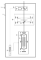
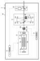
- 3 schematically shows the configuration of a laser device according to Embodiment 1.
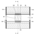
- FIG. 4 is a cross-sectional view showing details of the configuration of the Faraday rotator.
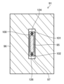
- FIG. 5 is a cross-sectional view along line 5-5 in FIG. FIG.
- FIG. 6 is an explanatory diagram showing an example of the polarization direction of pulsed laser light entering an optical pulse stretcher (OPS) and the polarization direction of pulsed laser light that has passed through the OPS.
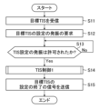
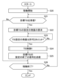
- 7 is a flowchart showing an example 1 of control processing in the laser device according to the first embodiment.
- FIG. FIG. 8 is a flowchart showing an example 2 of control processing in the laser device according to the first embodiment.
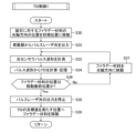
- FIG. 9 is a flow chart showing an example of a subroutine applied to step S14 of FIG. 7 or step S24 of FIG. 10 is a flowchart showing a modification of TIS control in the laser device according to Embodiment 1.
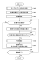
- FIG. FIG. 11 is a flow chart showing an example of a subroutine of processing applied to step S40 of FIG. FIG.
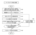
- FIG. 12 is a flowchart showing an example of a subroutine of processing applied to step S46 of FIG. 13 schematically shows the configuration of a laser device according to Modification 1 of Embodiment 1.
- FIG. FIG. 14 schematically shows the configuration of a laser device according to Modification 2 of Embodiment 1.
- FIG. 15 schematically shows the configuration of a laser device according to Embodiment 2.
- FIG. 16 is an explanatory diagram showing an example of the polarization direction of the pulsed laser light entering the second Faraday rotator and the polarization direction of the pulsed laser light that has passed through the OPS.
- 17 is a flowchart illustrating an example of control processing in the laser device according to the second embodiment;
- FIG. 18 is a flow chart showing an example of a subroutine of processing applied to step S74 of FIG.
- FIG. 19 schematically shows the configuration of a laser device according to Modification 1 of Embodiment 2.
- FIG. 20 schematically shows the configuration of a laser device according to Modification 2 of Embodiment 2.
- FIG. 21 schematically shows a configuration example of an exposure apparatus.
- Polarizer is an optical element that separates light in a specific polarization direction (transmission axis direction) from light whose polarization direction is orthogonal to that.
- transmission axis direction transmission axis direction
- each polarization component is separated by the following ratio.
- Malus' law Malus' law.
- FIG. 1 is a graph showing an example of the relationship between the angle between the transmission axis of the polarizer and the polarization direction of incident light and the transmittance.
- the horizontal axis of FIG. 1 represents the angle ⁇ between the transmission axis of the polarizer and the polarized light, and the vertical axis represents the transmittance.
- TIS Time-Integral Square
- I(t) represents the light intensity over time.
- FIG. 2 schematically shows the configuration of a laser apparatus 2 according to a comparative example.
- the comparative examples of the present disclosure are forms known by the applicant to be known only by the applicant, and not known examples to which the applicant admits.
- the laser device 2 includes an oscillator 10 , an optical pulse stretcher (OPS) 50 , a monitor module 60 and a laser controller 70 .
- OPS optical pulse stretcher
- OPS 50 and a monitor module 60 are arranged in this order on the optical path of the pulsed laser light output from the oscillator 10 .
- Oscillator 10 includes chamber 14 , rear mirror 17 and output coupling mirror 18 .
- the output coupling mirror 18 and the rear mirror 17 are arranged to form an optical resonator.
- the chamber 14 is arranged on the optical path of the optical resonator and includes a pair of discharge electrodes 15a and 15b and two windows 16a and 16b through which laser light is transmitted.
- An excimer laser gas is introduced into the chamber 14 .
- the excimer laser gas may contain, for example, Ar gas or Kr gas as a rare gas, F2 gas as a halogen gas, and Ne gas as a buffer gas.
- the OPS 50 includes a beam splitter 52 and concave mirrors 54a, 54b, 54c, and 54d, which form a delay optical path.
- the beam splitter 52 is arranged on the optical path of the laser light, and is coated with a film that transmits part of the pulsed laser light and reflects the other part of the pulsed laser light.
- the reflectance of beam splitter 52 is preferably about 60%.
- the beam splitter 52 causes the laser device 2 to output the pulsed laser light that has passed through the beam splitter 52 as described above.
- the concave mirrors 54a to 54d are all concave mirrors with substantially the same focal length f.
- the concave mirrors 54a-54d are arranged so as to have the following relationship. That is, the image at the position of the beam splitter 52 of the laser beam reflected by the beam splitter 52 is reversed by the concave mirrors 54a and 54b and formed into an image. Concave mirrors 54a-54d are arranged to return to the splitter 52 and form an image in the normal direction. In this case, the delay optical path length L is 8f.
- the monitor module 60 includes a beam splitter 62 and an optical sensor 63.
- Optical sensor 63 may be, for example, a biplanar discharge tube or a photodiode. Data measured using the optical sensor 63 is transmitted to the laser controller 70 .
- a high voltage pulse is applied between the discharge electrodes 15a and 15b in the chamber 14 from a power source (not shown).
- a discharge occurs between the discharge electrodes 15a and 15b in the chamber 14, the laser gas is excited, and an optical resonator composed of the output coupling mirror 18 and the rear mirror 17 emits a pulsed laser beam with an ultraviolet wavelength of 150 nm to 380 nm. is output from the out-coupling mirror 18 .
- the pulsed laser light output from the output coupling mirror 18 is incident on the OPS 50, and a portion of the pulsed laser light passes through the delay optical path within the OPS 50 multiple times, thereby being extended to a predetermined pulse width.
- a portion of the pulsed laser light that has passed through the OPS 50 is transmitted through the beam splitter 62 and output from the laser device 2 .
- Another portion of the pulsed laser beam that has passed through the OPS 50 is reflected by the beam splitter 62 and enters the optical sensor 63 .
- the optical sensor 63 measures the pulse energy E, and the obtained data is transmitted from the monitor module 60 to the laser controller 70 .
- the laser control unit 70 controls the voltage of the high voltage pulse output from the power source (not shown) so that the difference ⁇ E between the target pulse energy Et and the measured pulse energy E approaches zero.
- Method 1 requires preparing in advance a plurality of standard OPS housings with different circular optical path lengths. .
- method 2 it is necessary to prepare in advance a plurality of types of standard products with different reflectances of the beam splitter 52 .
- both method 1 and method 2 require replacement with a standard product, which requires a great deal of time and effort.
- only the configuration of the prepared standard product can be changed, and the degree of freedom of change is small, making it difficult to optimize the pulse width or pulse waveform.
- FIG. 3 schematically shows the configuration of a laser device 2A according to the first embodiment. Regarding the laser device 2A shown in FIG. 3, points different from the configuration shown in FIG. 2 will be described.
- the window 16b of the chamber 14 may be arranged, for example, at Brewster's angle.
- the polarization of the pulsed laser light emitted from the chamber 14 may be linear polarization or random polarization.
- the laser device 2A includes an OPS 51 instead of the OPS 50 in FIG.
- the OPS 51 has a Faraday rotator 91 arranged on a delay optical path composed of concave mirrors 54a to 54d.
- the Faraday rotator 91 is arranged, for example, on the optical path between the concave mirrors 54b and 54c.
- the Faraday rotator 91 may be placed anywhere on the delay optical path.
- the Faraday rotator 91 is preferably arranged on the optical path of the collimated light.
- a polarizer 53 is arranged in the OPS 51 instead of the beam splitter 52 in FIG.
- the polarizer 53 is coated with a film that highly transmits P-polarized light and highly reflects S-polarized light.
- Faraday rotator 91 includes Faraday material 95 and magnets 96 .
- the Faraday material 95 may be calcium fluoride ( CaF2 ) crystals or synthetic quartz.
- Magnet 96 may be a permanent magnet or an electromagnet.
- FIG. 4 is a cross-sectional view showing the details of the configuration of the Faraday rotator 91.
- FIG. FIG. 4 shows a cross section parallel to the optical axis of the pulsed laser beam.
- a centerline CL in FIG. 4 represents the center of the magnet 96 .
- FIG. 5 is a cross-sectional view along line 5-5 in FIG.
- the actuator 120 that controls the amount of rotation of the polarization direction is arranged on the Faraday rotator 91 .
- the actuator 120 may be, for example, a mechanism that moves the Faraday material 95 with respect to the magnet 96 in the optical axis direction of the pulsed laser beam.
- the movable amount (maximum amount of movement) of the Faraday material 95 by the actuator 120 is preferably at least half the length of the pulsed laser beam of the Faraday material 95 in the optical axis direction.
- a minimum unit of movement of the Faraday material 95 by the actuator 120 may be, for example, about 0.2 mm.
- the actuator 120 may be configured to move the magnet 96 with respect to the Faraday material 95 in the optical axis direction of the pulsed laser beam.
- the Faraday rotator 91 is an example of the "first Faraday rotator” in the present disclosure.
- Faraday material 95 and magnet 96 are examples of “first Faraday material” and “first magnet” in this disclosure.
- Actuator 120 is an example of a "first actuator” in the present disclosure.
- the actuator 120 is not limited to a moving mechanism for relatively moving the Faraday material 95 and the magnet 96.
- the magnet 96 may be an electromagnet and a mechanism for controlling the current flowing through the electromagnet, or a heater or the like. may be a mechanism for controlling the temperature of the magnet 96 using
- the term "actuator” is not limited to a device that performs a mechanical operation, and refers to a mechanism (mechanism) capable of changing the amount of rotation of the polarization direction by the Faraday rotator 91 by changing current, temperature, etc. It is used as a term for the concept that also includes
- the cross-sectional shape of the Faraday material 95 may also be a vertically long rectangle.
- the cross-sectional shape of the magnetic field generating portion 97 of the magnet 96 where the Faraday material 95 is arranged may be a vertically long rectangle oriented in the same direction as the cross-sectional shape of the Faraday material 95 .
- the Faraday material 95 is placed in the magnetic field generating portion 97 of the magnet 96 while being held by the Faraday material holder 100 .
- the cross-sectional shape of the Faraday material holder 100 perpendicular to the optical axis of the pulsed laser beam may be a vertically long rectangle like the Faraday material 95 .
- a through hole 101 is formed at one end of the Faraday material holder 100 in the longitudinal direction of the oblong rectangle, and a female screw hole 102 is formed at the other end.
- a guide shaft 124 is inserted into the through hole 101, and a rod-shaped male screw 126 is screwed into the hole 102 of the female screw.
- the Faraday material holder 100 is held by the plates 121a and 121b via the guide shaft 124 and the male screw 126.
- Male screw 126 is rotatably held and connected to actuator 120 .
- Magnets 96 are also held between plates 121a and 121b.
- Actuator 120 is an example of the "first movement mechanism" in the present disclosure.
- the laser device 2A includes an OPS control section 72 that receives the measurement result of the optical sensor 63 and controls the actuator 120.
- the OPS controller 72 is connected to the laser controller 70 .
- the OPS controller 72 can receive the measurement result of the optical sensor 63 via the laser controller 70 .
- Each of the laser control unit 70 and the OPS control unit 72 is configured using a processor.
- a processor of the present disclosure is a processing device that includes a storage device that stores a control program and a CPU (Central Processing Unit) that executes the control program.
- the processor is specially configured or programmed to perform the various processes contained in this disclosure.
- the processor may include an integrated circuit typified by FPGA (Field Programmable Gate Array) and ASIC (Application Specific Integrated Circuit).
- the processing functions of the OPS controller 72 may be incorporated within the laser controller 70 .
- the functions of laser controller 70 and OPS controller 72 may be implemented by one or more processors.
- the strength of the magnetic field of the magnetic field generator 97 of the magnet 96 changes depending on the position in the optical axis direction. Therefore, by changing the position of the Faraday material 95 in the optical axis direction of the pulsed laser light with respect to the magnet 96 with the actuator 120, the amount of rotation of the polarization of the pulsed laser light by the Faraday rotator 91 can be controlled.
- the pulsed laser light output from the oscillator 10 and polarized in a specific direction is transmitted through the polarizer 53 in the component parallel to the transmission axis of the polarizer 53 and passes through the OPS 51 .
- a component orthogonal to the transmission axis of the polarizer 53 is reflected by the polarizer 53 and propagates through the delay optical path within the OPS 51 .
- FIG. 6 is an explanatory diagram showing an example of the polarization direction of the pulsed laser light incident on the OPS 51 and the polarization direction of the pulsed laser light that has passed through the OPS 51 .
- a double-headed arrow shown in a circle in FIG. 6 represents the polarization direction of the pulsed laser beam.
- FIG. 6 shows the polarization direction of the pulsed laser beam when viewed in the propagation direction of the pulsed laser beam.
- the pulsed laser beam component transmitted through the polarizer 53 passes through the OPS 51 , and the pulsed laser beam component reflected by the polarizer 53 propagates through the delay optical path in the OPS 51 .
- a pulsed laser beam component reflected by the polarizer 53 may pass through the OPS 51 .
- a Faraday rotator 91 rotates the polarization direction of the pulsed laser light reflected by the polarizer 53, concave mirror 54a, and concave mirror 54b.
- the pulsed laser light whose polarization direction has been rotated returns to the polarizer 53, and the component parallel to the transmission axis of the polarizer 53 is transmitted and propagates through the delay optical path within the OPS 2 again.
- Components orthogonal to the transmission axis of polarizer 53 are reflected and pass through OPS 51 .
- perpendicular or “perpendicular” in this specification is not limited to being strictly perpendicular or perpendicular unless otherwise specified, unless otherwise clear from the context. It includes the concept of substantially perpendicular or substantially perpendicular, including a range of practically acceptable angular differences that are not equal to each other.
- parallel in this specification is not limited to being strictly parallel unless otherwise specified, except where it is clear from the context. It includes the concept of near-parallel, which includes the range of angular differences between
- the OPS control unit 72 can control the actuator 120 of the Faraday rotator 91 to change the amount of rotation of the polarization direction.
- the OPS control unit 72 controls the actuator 120 to move the Faraday material 95 in the optical axis direction by a predetermined movement amount to change the polarization direction, and based on the measurement result of the optical sensor 63 for each position of the Faraday material 95. , may determine the amount of rotation of the Faraday rotator 91 .
- the concave mirrors 54a, 54b, 54c, and 54d forming the delay optical path of the OPS 51 are an example of the "delay optical system" in the present disclosure.
- the concave mirrors 54a, 54b, 54c, and 54d are examples of "a plurality of mirrors" in the present disclosure.
- FIG. 7 is a flowchart showing an example 1 of control processing in the laser device 2A according to the first embodiment.
- FIG. 7 shows a flow in which the OPS control unit 72 obtains the pulse waveform from the optical sensor 63, calculates the pulse width (TIS), and controls the Faraday rotator 91 so that the TIS satisfies the target. .
- TIS pulse width
- the OPS control unit 72 receives the target TIS.
- the target TIS may be received from, for example, a processing device or exposure device (not shown).
- step S12 the OPS control unit 72 issues an oscillation request for setting the target TIS.
- step S13 the OPS control unit 72 determines whether or not the TIS setting oscillation is permitted. When the determination result of step S13 is No determination, the OPS control unit 72 repeats step S13.
- step S14 the OPS control unit 72 performs first TIS control.
- the first TIS control is denoted as "TIS control 1".
- the first TIS control subroutine applied to step S14 will be described later with reference to FIG.
- step S15 after step S14, the OPS control unit 72 transmits a signal indicating the end of setting the target TIS.
- step S15 the OPS control unit 72 terminates the flowchart of FIG.
- FIG. 8 is a flowchart showing an example 2 of control processing in the laser device 2A according to the first embodiment.
- the flowchart shown in FIG. 8 may be executed, for example, after the flowchart in FIG. 7 is completed.
- step S20 the laser control unit 70 starts operating the laser device 2A.
- step S21 the OPS control unit 72 determines whether or not the target TIS has been received.
- the OPS control unit 72 proceeds to step S22.
- Each step from step S22 to step S25 may be the same as the corresponding step from step S12 to step S15 in FIG. 7, and redundant description will be omitted.
- step S26 after step S25, the laser control unit 70 determines whether or not to end the operation of the laser device 2A. When the determination result of step S26 is No determination, it returns to step S21.
- step S21 determines whether the OPS control unit 72 is a correct OPS control unit 72 is a correct OPS control unit 72 . If the determination result of step S21 is No, the OPS control unit 72 proceeds to step S26.
- step S26 If the determination result in step S26 is Yes, the laser control unit 70 stops the laser device 2A and terminates the flowchart of FIG.
- FIG. 9 is a flow chart showing an example of a subroutine applied to step S14 of FIG. 7 or step S24 of FIG.
- step S30 the OPS control unit 72 moves the position of the Faraday material 95 with respect to the magnet 96 in the optical axis direction to the initial position.
- the position of the Faraday material 95 in the optical axis direction is defined by the central position of the Faraday material 95, for example.
- the initial position of Faraday material 95 may be, for example, the center position of magnet 96 .
- step S32 the OPS control unit 72 causes the oscillator 10 to output pulsed laser light.
- step S33 the OPS control unit 72 measures the pulse waveform with the optical sensor 63.
- step S34 the OPS control unit 72 calculates the TIS from the measured pulse waveform, and stores the calculated TIS value in association with the position of the Faraday material 95.
- step S36 the OPS control unit 72 determines whether the position of the Faraday material 95 is the final movement position. If the determination result in step S36 is No, the OPS controller 72 proceeds to step S37 and moves the Faraday material 95 in the optical axis direction. The amount of movement at this time may be a predetermined amount of movement, such as 0.5 mm. After step S37, the process returns to step S33.
- step S36 If the determination result of step S36 is Yes, the OPS control unit 72 proceeds to step S38.
- step S38 the OPS control unit 72 stops outputting the pulsed laser beam.
- step S39 the OPS control unit 72 moves the Faraday material 95 to a position that satisfies the target value of TIS (target TIS).
- target TIS target TIS
- the OPS controller 72 may move the Faraday material 95 to the position where the TIS is the longest.
- the OPS control unit 72 controls the actuator 120 so that the TIS becomes equal to or greater than the target value.
- step S39 the OPS control unit 72 ends the flowchart in FIG. 9 and returns to the flowchart in FIG. 7 or 8.
- FIG. 10 is a flow chart showing a modification of TIS control in the laser device 2A according to the first embodiment.
- the flowchart of FIG. 10 is an example of a method of preparing table data describing the relationship between the TIS and the position of the Faraday material 95 in advance and controlling the Faraday rotator 91 based on this table data.
- step S40 the OPS control unit 72 creates and stores table data. A subroutine of the processing applied to step S40 will be described later using FIG.
- step S41 the OPS control unit 72 transmits an oscillation preparation completion signal.
- step S42 the laser control unit 70 starts operating the laser device 2A.
- steps S43 to S48 may be the same as the corresponding steps of steps S21 to S26 in FIG. However, instead of step S24 in FIG. 8, step S46 is included in FIG.
- step S46 the OPS control unit 72 performs the second TIS control.
- the second TIS control subroutine applied to step S46 will be described later with reference to FIG.
- FIG. 11 is a flowchart showing an example of a subroutine of processing applied to step S40 of FIG.
- step S50 the OPS control unit 72 moves the position of the Faraday material 95 with respect to the magnet 96 in the optical axis direction to the initial position.
- step S50 to step S54 may be the same as the corresponding step from step S30 to step S34 in FIG.
- step S55 after step S54, the OPS control unit 72 records the position of the Faraday material 95 and the data of the TIS in table data.
- step S56 the OPS control unit 72 determines whether the position of the Faraday material 95 is the final movement position.
- step S56 to step S58 may be the same as the corresponding step from step S36 to step S38 in FIG.
- table data indicating the relationship between the position of the Faraday material 95 and the TIS is obtained. Since the position of the Faraday material 95 corresponds to the control amount of the actuator 120 , the table data may define the relationship between the TIS and the control amount of the actuator 120 .
- step S58 the OPS control unit 72 ends the flowchart of FIG. 11 and returns to the flowchart of FIG.
- FIG. 12 is a flowchart showing an example of a subroutine of processing applied to step S46 of FIG.
- the OPS control unit 72 reads the target position of the Faraday material 95 capable of achieving the target TIS from the table data.
- step S61 the OPS control unit 72 drives the actuator 120 so as to move the Faraday material 95 to the target position.
- step S61 the OPS control unit 72 ends the flowchart in FIG. 12 and returns to the flowchart in FIG.
- the pulse width (TIS) can be changed to an arbitrary pulse width without changing the constituent elements of the optical system, such as changing the circuit optical path length or changing the optical parts. Further, according to the OPS 51 according to the first embodiment, it is possible to satisfy the target value of the pulse width (TIS) without changing the components of the optical system.
- FIG. 13 schematically shows the configuration of a laser device 2B according to Modification 1 of Embodiment 1. As shown in FIG. Regarding the configuration shown in FIG. 13, points different from FIG. 3 will be described.
- the oscillator 10A of the laser device 2B includes a band narrowing module (LNM) 11 instead of the rear mirror 17 of FIG.
- LNM 11 includes a prism beam expander 12 for narrowing the spectral linewidth and a grating 13 .
- the prism beam expander 12 and the grating 13 are arranged in a Littrow arrangement in which the incident angle and the diffraction angle match.
- the LNM 11 is an example of a "band-narrowing optical system" in the present disclosure.
- the output coupling mirror 18 is a reflecting mirror with a reflectance of 40% to 60%. Output coupling mirror 18 and LNM 11 are arranged to form an optical resonator.
- a high voltage pulse is applied to the discharge electrodes 15a and 15b in the chamber 14 from a power source (not shown).
- a discharge is generated between the discharge electrodes 15a and 15b in the chamber 14, the laser gas is excited, and an ultraviolet wavelength of 150 nm to 380 nm narrowed by the optical resonator composed of the output coupling mirror 18 and the LNM 11. of pulsed laser light is output from the output coupling mirror 18 .
- Other operations are the same as those of the laser device 2A according to the first embodiment described with reference to FIG.
- the pulsed laser light of the narrowed ultraviolet wavelength can be changed to an arbitrary pulse width and pulse waveform without changing the components of the optical system.
- FIG. 14 schematically shows the configuration of a laser device 2C according to Modification 2 of Embodiment 1. As shown in FIG. Regarding the configuration shown in FIG. 14, points different from FIG. 3 will be described.
- the laser device 2C is composed of a MOPO (Master Oscillator Power Oscillator) system in which the oscillator 10 portion of FIG.
- An MO beam steering unit 20 is arranged between the oscillation stage laser 10 A and the amplification stage laser 30
- a PO beam steering unit 40 is arranged between the amplification stage laser 30 and the OPS 51 .
- the oscillation stage laser 10A includes an LNM 11, a chamber 14, and an output coupling mirror 18.
- the configuration of the oscillation stage laser 10A may be the same as that of the oscillator 10 described with reference to FIG.
- the MO beam steering unit 20 includes a high reflection mirror 21 and a high reflection mirror 22 and is arranged so that the pulsed laser light output from the oscillation stage laser 10A is incident on the amplification stage laser 30 .
- the amplification stage laser 30 includes a chamber 34 , a rear mirror 37 and an output coupling mirror 38 .
- the output coupling mirror 38 and the rear mirror 37 constitute an optical resonator, and the chamber 34 is arranged on the optical path of this optical resonator.
- Amplification stage laser 30 is an example of an "amplifier" in this disclosure.
- the configuration of the chamber 34 may be similar to that of the chamber 14.
- the chamber 34 includes a pair of discharge electrodes 35a, 35b and two windows 36a, 36b, and an excimer laser gas is introduced into the chamber 34. As shown in FIG.
- the rear mirror 37 may be a partially reflective mirror with a reflectance of 50% to 90%.
- Out-coupling mirror 38 may be a partially reflective mirror with a reflectivity of 10% to 30%.
- the PO beam steering unit 40 includes a high reflection mirror 43 and a high reflection mirror 44 and is arranged so that the pulsed laser light output from the amplification stage laser 30 is incident on the OPS 51 .
- a high voltage pulse is applied between the discharge electrodes 15a and 15b in the chamber 14 from a power source (not shown).
- a discharge is generated between the discharge electrodes 15a and 15b in the chamber 14, the laser gas is excited, and an ultraviolet wavelength of 150 nm to 380 nm narrowed by the optical resonator composed of the output coupling mirror 18 and the LNM 11. of pulsed laser light is output from the output coupling mirror 18 .
- the pulsed laser light output from the output coupling mirror 18 passes through the MO beam steering unit 20 and enters the rear mirror 37 of the amplification stage laser 30 as seed light.
- the pulsed laser beam output from the output coupling mirror 18 is an example of the "first pulsed laser beam" in the present disclosure.
- a high voltage pulse is applied between the discharge electrodes 35 a and 35 b in the chamber 34 from a power source (not shown) at the timing when the seed light transmitted through the rear mirror 37 enters the chamber 34 .
- a discharge is generated between the discharge electrodes 35a and 35b in the chamber 34, the laser gas is excited, the seed light is amplified by the Fabry-Perot optical resonator composed of the output coupling mirror 38 and the rear mirror 37, and the output coupling mirror
- the amplified pulsed laser light is output from 38 .
- the pulsed laser light output from the amplification stage laser 30 enters the OPS 51 via the PO beam steering unit 40 .
- the operation of the OPS 51 is the same as in the first embodiment.
- the high-energy pulsed laser light with a narrowed ultraviolet wavelength can be changed to an arbitrary pulse width and pulse waveform without changing the components of the optical system.
- FIG. 15 schematically shows the configuration of a laser device 2D according to the second embodiment. Regarding the configuration shown in FIG. 15, points different from FIG. 3 will be described.
- a Faraday rotator 202 is arranged upstream of the OPS 51 in the laser device 2D.
- Faraday rotator 202 includes Faraday material 205 and magnets 206 .
- the structure of the Faraday rotator 202 may be similar to the structure of the Faraday rotator 91 described in FIGS.
- the Faraday rotator 202 is provided with an actuator (not shown) that moves the Faraday material 205 with respect to the magnet 206 in the optical axis direction of the pulsed laser beam.
- the Faraday rotator 91 disposed in the delay optical path of the OPS 51 is referred to as the first Faraday rotator 91
- the Faraday rotator 202 disposed upstream of the OPS 51 is referred to as the second Faraday rotator 202. and described.
- the Faraday material 95, the magnet 96, and the actuator 120 of the first Faraday rotator 91 are referred to as the first Faraday material 95, the first magnet 96, and the first actuator 120, and the second Faraday rotation
- the Faraday material 205, magnet 206 and actuator of child 202 are referred to as second Faraday material 205, second magnet 206 and second actuator.
- the maximum amount of movement of the second Faraday material 205 by the second actuator is preferably at least half the length of the second Faraday material 205 in the optical axis direction of the pulsed laser beam.
- the minimum movement unit of the second actuator may be approximately 0.2 mm, for example.
- the second actuator may move the second magnet 206 with respect to the second Faraday material 205 in the optical axis direction of the pulsed laser beam.
- a second actuator is an example of a "second moving mechanism" in the present disclosure.
- FIG. 16 is an explanatory diagram showing an example of the polarization direction of the pulsed laser light entering the second Faraday rotator 202 and the polarization direction of the pulsed laser light that has passed through the OPS 51 .
- the second Faraday rotator 202 rotates the polarization direction of the pulsed laser light polarized in a specific direction output from the amplification stage laser 30 .
- FIG. 16 shows an example in which the polarization direction rotates clockwise.
- the pulsed laser beam whose polarization direction has been rotated passes through the OPS 51 through the polarizer 53 , which transmits the component parallel to the transmission axis of the polarizer 53 .
- a component orthogonal to the transmission axis of the polarizer 53 is reflected by the polarizer 53 and propagates through the delay optical path within the OPS 51 .
- the pulsed laser beam component transmitted through the polarizer 53 passes through the OPS 51 , and the pulsed laser beam component reflected by the polarizer 53 propagates through the delay optical path in the OPS 51 .
- the reflected pulsed laser beam component may propagate through the delay optical path in the OPS 51 , and the reflected pulsed laser beam component may pass through the OPS 51 .
- the pulsed laser beam reflected by the polarizer 53 is rotated in the polarization direction by the first Faraday rotator 91 on the delay optical path in the OPS 51 .
- the pulsed laser light whose polarization direction has been rotated by the first Faraday rotator 91 returns to the polarizer 53 , and the component parallel to the transmission axis of the polarizer 53 is transmitted and propagates through the delay optical path in the OPS 51 again.
- the component orthogonal to the transmission axis of the polarizer 53 is reflected and passes through the OPS 51 .
- the OPS control unit 72 may control the first actuator 120 of the first Faraday rotator 91 to change the amount of rotation of the polarization direction.
- the OPS controller 72 may control the second actuator of the second Faraday rotator 202 to change the amount of rotation of the polarization direction.
- the OPS control unit 72 may determine the amount of rotation of the first Faraday rotator 91 based on the measurement result of the optical sensor 63 .
- the OPS controller 72 may determine the amount of rotation of the second Faraday rotator 202 based on the measurement result of the optical sensor 63 .
- the OPS control unit 72 may control the amount of rotation of the second Faraday rotator 202 in order to change the waveform of the first half of the pulse waveform of the pulse laser light output from the laser device 2D.
- the OPS control unit 72 may control the amount of rotation of the first Faraday rotator 91 in order to change the waveform of the latter half of the pulse waveform of the pulse laser light output from the laser device 2D.
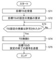
- FIG. 17 is a flowchart showing an example of control processing in the laser device 2D according to the second embodiment. Regarding the flow chart of FIG. 17, points different from FIG. 7 will be described.
- Steps S71 to S73 of FIG. 17 are the same as the corresponding steps of steps S11 to S13 of FIG.
- the flowchart of FIG. 17 includes step S74 instead of step S14 of FIG.
- step S73 the OPS control unit 72 proceeds to step S74.
- step S74 the OPS control unit 72 performs third TIS control. The third TIS control subroutine applied to step S74 will be described later with reference to FIG.
- Step S75 after step S74 is the same as step S15 in FIG. After step S75, the OPS control unit 72 terminates the flowchart of FIG.
- FIG. 18 is a flowchart showing an example of the third TIS control.
- the flowchart of FIG. 18 is an example of a subroutine of processing applied to step S74 of FIG.
- the first Faraday material 95 is referred to as "Faraday material 1”
- the first magnet 96 as “Magnet 1”
- the second Faraday material 205 as “Faraday material 2”
- the second magnet 206 is denoted as "magnet 2”.
- step S80 the OPS control unit 72 moves the position of the first Faraday material 95 with respect to the first magnet 96 in the optical axis direction to the initial position.
- Step S80 may be similar to step S30 of FIG.
- step S81 the OPS control unit 72 moves the position of the second Faraday material 205 with respect to the second magnet 206 in the optical axis direction to the initial position.
- the position of the second Faraday material 205 in the optical axis direction is defined by the central position of the second Faraday material 205, for example.
- the initial position of the second Faraday material 205 may be, for example, the central position of the second magnet 206 .
- step S82 the OPS control unit 72 causes the oscillator 10 to output pulsed laser light.
- step S83 the OPS control unit 72 measures the pulse waveform with the optical sensor 63. Then, in step S84, the OPS controller 72 calculates TIS from the measured pulse waveform and stores the value in association with the positions of the first Faraday material 95 and the second Faraday material 205. FIG.
- step S86 the OPS control unit 72 determines whether or not the position of the first Faraday material 95 is the final movement position. If the determination result in step S86 is No, the OPS controller 72 proceeds to step S87 and moves the first Faraday material 95 in the optical axis direction. Steps S86 and S87 are the same as steps S36 and S37 in FIG. After step S87, the process returns to step S83.
- step S86 the OPS control unit 72 proceeds to step S90.
- step S90 the OPS controller 72 determines whether the position of the second Faraday material 205 is the final movement position. If the determination result in step S90 is No, the OPS controller 72 proceeds to step S91 and moves the first Faraday material 95 to the initial position.
- step S92 the OPS controller 72 moves the second Faraday material 205 in the optical axis direction.
- the amount of movement at this time may be a predetermined amount of movement, such as 0.5 mm.
- step S90 the OPS control unit 72 proceeds to step S94.
- step S94 the OPS controller 72 stops outputting the pulsed laser beam.
- step S96 the OPS control unit 72 moves the first Faraday material 95 and the second Faraday material 205 to a position that satisfies the target value of TIS (target TIS).
- target TIS target TIS
- the OPS controller 72 may move the first Faraday material 95 and the second Faraday material 205 to the position where the TIS is the longest.
- step S96 the OPS control unit 72 ends the flowchart in FIG. 18 and returns to the flowchart in FIG.
- the relationship between the TIS, the position of the first Faraday material 95, and the position of the second Faraday material 205 is similar to the examples described with reference to FIGS. may be prepared in advance, and the first Faraday rotator 91 and the second Faraday rotator 202 may be controlled based on this table data.
- the pulse width and change the pulse waveform of the pulsed laser light without changing the components of the optical system, such as changing the optical path length or changing the optical components. can.
- the target value of the pulse width (TIS) can be satisfied without changing the components of the optical system.
- the pulsed laser light incident on the OPS 51 and the transmission axis of the polarizer 53 are orthogonal to each other, all components of the pulsed laser light are reflected by the polarizer 53 and propagate through the delay optical path. Then, only the pulsed laser light component orthogonal to the transmission axis of the polarizer 53 is reflected by the polarizer 53 and passes through the OPS 51 . Therefore, the pulsed laser light that has passed through the OPS 51 has only components perpendicular to the transmission axis of the polarizer 53 (high polarization purity).
- the configuration of the second embodiment can be applied to applications requiring high polarization purity, such as light sources for exposure apparatuses.
- FIG. 19 schematically shows the configuration of a laser device 2E according to Modification 1 of Embodiment 2. As shown in FIG. Regarding the configuration shown in FIG. 19, the differences from FIG. 15 will be described.
- the oscillator 10A of the laser device 2E includes an LNM11 instead of the rear mirror 17 in FIG.
- the configuration of LNM 11 may be similar to that of FIG.
- the pulsed laser light of the narrowed ultraviolet wavelength can be changed to an arbitrary pulse width and pulse waveform without changing the components of the optical system.
- FIG. 20 schematically shows the configuration of a laser device 2F according to Modification 2 of Embodiment 2. As shown in FIG. Regarding the configuration shown in FIG. 20, points different from FIG. 15 will be described.
- the laser device 2F is composed of a MOPO (Master Oscillator Power Oscillator) system in which the oscillator 10A portion in FIG.
- An MO beam steering unit 20 is arranged between the oscillation stage laser 10 A and the amplification stage laser 30
- a PO beam steering unit 40 is arranged between the amplification stage laser 30 and the OPS 51 .
- the configurations of the oscillation stage laser 10A, the MO beam steering unit 20, the amplification stage laser 30 and the PO beam steering unit 40 may be the same as in FIG.
- the high-energy pulsed laser light of the narrowed ultraviolet wavelength can be changed to an arbitrary pulse width and pulse waveform without changing the components of the optical system.
- the configuration of the oscillation stage laser 10A shown in FIGS. 14 and 19 is not limiting, and a solid-state laser system including a semiconductor laser and a wavelength conversion system, for example, may be employed.
- a wavelength conversion system may be constructed using a nonlinear optical crystal. That is, the oscillation stage laser is not limited to a gas laser, and may be an ultraviolet solid-state laser that outputs pulsed laser light with an ultraviolet wavelength.
- the oscillation stage laser may be a solid-state laser that oscillates at a wavelength of approximately 193.4 nm, or an ultraviolet solid-state laser that outputs fourth harmonic light of a titanium sapphire laser (wavelength of approximately 774 nm).
- the amplifier is not limited to a configuration having a Fabry-Perot resonator such as the amplification-stage laser 30 shown in FIG. 14, and may have a configuration having a ring resonator. Further, the amplifier is not limited to a configuration having an optical resonator, and may be a simple amplifier such as an excimer amplifier.
- the amplifier may be a multi-pass amplifier such as a 3-pass amplifier that amplifies the seed light by reflecting it off a cylindrical mirror and passing it through the discharge space three times.
- FIG. 21 schematically shows a configuration example of an exposure apparatus 80 .
- Exposure apparatus 80 includes illumination optical system 804 and projection optical system 806 .
- the laser device 2 ⁇ /b>A generates laser light and outputs the laser light to the exposure device 80 .
- the illumination optical system 804 illuminates a reticle pattern of a reticle (not shown) placed on the reticle stage RT with the laser light incident from the laser device 2A.
- the projection optical system 806 reduces and projects the laser light transmitted through the reticle to form an image on a workpiece (not shown) placed on the workpiece table WT.
- the workpiece is a photosensitive substrate, such as a semiconductor wafer, coated with photoresist.
- the exposure apparatus 80 synchronously translates the reticle stage RT and the workpiece table WT, thereby exposing the workpiece to laser light reflecting the reticle pattern.
- a semiconductor device can be manufactured through a plurality of processes.
- a semiconductor device is an example of an "electronic device" in this disclosure.
- Laser devices 2B to 2F may be used instead of the laser device 2A.
Landscapes
- Physics & Mathematics (AREA)
- General Physics & Mathematics (AREA)
- Optics & Photonics (AREA)
- Engineering & Computer Science (AREA)
- Electromagnetism (AREA)
- Nonlinear Science (AREA)
- Plasma & Fusion (AREA)
- Power Engineering (AREA)
- Lasers (AREA)
Abstract
Description
1.用語の説明
1.1 偏光子
1.2 TIS(Time-Integral Square)
2.比較例に係るレーザ装置の概要
2.1 構成
2.2 動作
2.3 課題
3.実施形態1
3.1 構成
3.2 動作
3.3 制御フローの例1
3.4 制御フローの例2
3.5 効果
3.6 変形例1
3.6.1 構成
3.6.2 動作
3.6.3 効果
3.7 変形例2
3.7.1 構成
3.7.2 動作
3.7.3 効果
4.実施形態2
4.1 構成
4.2 動作
4.3 制御フローの例
4.4 効果
4.5 変形例1
4.5.1 構成
4.5.2 動作
4.5.3 効果
4.6 変形例2
4.6.1 構成
4.6.2 動作
4.6.3 効果
5.レーザ装置の変形例
6.電子デバイスの製造方法について
7.その他
以下、本開示の実施形態について、図面を参照しながら詳しく説明する。以下に説明される実施形態は、本開示のいくつかの例を示すものであって、本開示の内容を限定するものではない。また、各実施形態で説明される構成及び動作の全てが本開示の構成及び動作として必須であるとは限らない。なお、同一の構成要素には同一の参照符号を付して、重複する説明を省略する。
1.1 偏光子
偏光子とは、特定の偏光方向(透過軸方向)の光とそれと偏光方向が直交する光を分離する光学素子をいう。偏光子の透過軸に対して光の偏光方向がθ度傾いている場合、各偏光成分は下式の割合で分離される。下式の関係をマリュー(Malus)の法則という。

TISは、レーザ光のパルス幅の長さを表す指標であり、下式より計算される。

2.1 構成
図2は、比較例に係るレーザ装置2の構成を概略的に示す。本開示の比較例とは、出願人のみによって知られていると出願人が認識している形態であって、出願人が自認している公知例ではない。レーザ装置2は、発振器10と、光学パルスストレッチャ(Optical Pulse Stretcher:OPS)50と、モニタモジュール60と、レーザ制御部70と、を含む。
レーザ制御部70の制御に基づき、不図示の電源より高電圧パルスがチャンバ14内の放電電極15a、15b間に印加される。チャンバ14内の放電電極15a、15b間で放電が発生すると、レーザガスが励起され、出力結合ミラー18とリアミラー17とで構成される光共振器によって、波長が150nmから380nmの紫外線波長のパルスレーザ光が出力結合ミラー18から出力される。
OPS50で伸長されるパルス幅又はパルス波形を変更する方法には例えば以下の2つがある。
[方法2]ビームスプリッタ52の反射率の変更
方法1は、周回光路長が異なる複数種類のOPSの筐体の水準品を事前に用意しておく必要がある。方法2は、ビームスプリッタ52の反射率が異なる複数種類の水準品を事前に用意しておく必要がある。さらに、方法1及び方法2のどちらの方法も水準品への交換が必要で交換作業の手間が大きくかかる。また、変更できるのは、用意した水準品の構成のみであり、変更の自由度も小さく、パルス幅又はパルス波形の最適化が困難である。
3.1 構成
図3は、実施形態1に係るレーザ装置2Aの構成を概略的に示す。図3に示すレーザ装置2Aについて、図2に示す構成と異なる点を説明する。
特定の方向に偏光したパルスレーザ光が、磁場が印加されたファラデー材料95を透過するとき、偏光方向が回転する。ファラデー回転子91でのパルスレーザ光の偏光方向の回転量は、磁場の強さ、ファラデー材料95が持つ屈折率などの物理量及びファラデー材料95の長さで決まる。
図7は、実施形態1に係るレーザ装置2Aにおける制御処理の例1を示すフローチャートである。図7には、OPS制御部72が光センサ63よりパルス波形を取得してパルス幅(TIS)を計算し、TISが目標を満たすように、ファラデー回転子91を制御するフローが示されている。
図10は、実施形態1に係るレーザ装置2AにおけるTIS制御の変形例を示すフローチャートである。図10のフローチャートは、予めTISとファラデー材料95の位置との関係を記述したテーブルデータを作成しておき、このテーブルデータに基づいてファラデー回転子91を制御する方法の例である。
実施形態1に係るOPS51によれば、周回光路長の変更や光学部品の変更といった光学系の構成要素の変更を行うことなく、任意のパルス幅(TIS)に変更できる。また、実施形態1に係るOPS51によれば、光学系の構成要素を変更せずに、パルス幅(TIS)の目標値を満たすことができる。
3.6.1 構成
図13は、実施形態1の変形例1に係るレーザ装置2Bの構成を概略的に示す。図13に示す構成について、図3と異なる点を説明する。
レーザ制御部70の制御に基づき、不図示の電源より高電圧パルスがチャンバ14内の放電電極15a、15bに印加される。チャンバ14内の放電電極15a、15b間で放電が発生すると、レーザガスが励起され、出力結合ミラー18とLNM11とで構成される光共振器によって、狭帯域化された波長が150nmから380nmの紫外線波長のパルスレーザ光が出力結合ミラー18から出力される。その他の動作は、図3で説明した実施形態1に係るレーザ装置2Aの動作と同様である。
実施形態1の変形例1に係るレーザ装置2Bによれば、狭帯域化された紫外線波長のパルスレーザ光のパルス幅を伸長及びパルス波形を変更することができる。
3.7.1 構成
図14は、実施形態1の変形例2に係るレーザ装置2Cの構成を概略的に示す。図14に示す構成について、図3と異なる点を説明する。
レーザ制御部70の制御に基づき、不図示の電源より高電圧パルスがチャンバ14内の放電電極15a、15b間に印加される。チャンバ14内の放電電極15a、15b間で放電が発生すると、レーザガスが励起され、出力結合ミラー18とLNM11とで構成される光共振器によって、狭帯域化された波長が150nmから380nmの紫外線波長のパルスレーザ光が出力結合ミラー18から出力される。
実施形態1の変形例2に係るレーザ装置2Cによれば、狭帯域化された紫外線波長の高エネルギのパルスレーザ光のパルス幅を伸長及びパルス波形を変更することができる。
4.1 構成
図15は、実施形態2に係るレーザ装置2Dの構成を概略的に示す。図15に示す構成について、図3と異なる点を説明する。
図16は、第2のファラデー回転子202に入射するパルスレーザ光の偏光方向と、OPS51を通過したパルスレーザ光の偏光方向との例を示す説明図である。
図17は、実施形態2に係るレーザ装置2Dにおける制御処理の例を示すフローチャートである。図17のフローチャートについて、図7と異なる点を説明する。
実施形態2によれば、周回光路長の変更や光学部品の変更といった光学系の構成要素の変更を行うことなく、パルスレーザ光のパルス幅を伸長及びパルス波形を変更することができる。また、実施形態2によれば、光学系の構成要素を変更せずに、パルス幅(TIS)の目標値を満たすことができる。
4.5.1 構成
図19は、実施形態2の変形例1に係るレーザ装置2Eの構成を概略的に示す。図19に示す構成について、図15と異なる点を説明する。
レーザ装置2Eの発振器10Aの動作は、図13の発振器10Aと同様である。その他の動作は、図15で説明した実施形態2に係るレーザ装置2Dの動作と同様である。
実施形態2の変形例1に係るレーザ装置2Eによれば、狭帯域化された紫外線波長のパルスレーザ光のパルス幅を伸長及びパルス波形を変更することができる。
4.6.1 構成
図20は、実施形態2の変形例2に係るレーザ装置2Fの構成を概略的に示す。図20に示す構成について、図15と異なる点を説明する。
レーザ装置2Fの動作は、レーザ装置2Cの動作と同様である。
実施形態2の変形例2に係るレーザ装置2Fによれば、狭帯域化された紫外線波長の高エネルギのパルスレーザ光のパルス幅を伸長及びパルス波形を変更することができる。
図14及び図19に示す発振段レーザ10Aの構成に限らず、例えば、半導体レーザと、波長変換システムとを含む固体レーザシステムを採用してもよい。波長変換システムは非線形光学結晶を用いて構成し得る。すなわち、発振段レーザは、ガスレーザに限らず、紫外線波長のパルスレーザ光を出力する紫外線固体レーザであってもよい。例えば、発振段レーザは、波長約193.4nmを発振する固体レーザ、あるいは、チタンサファイヤレーザ(波長約774nm)の第4高調波光を出力する紫外線固体レーザでもよい。
図21は、露光装置80の構成例を概略的に示す。露光装置80は、照明光学系804と投影光学系806とを含む。レーザ装置2Aはレーザ光を生成し、レーザ光を露光装置80に出力する。照明光学系804は、レーザ装置2Aから入射したレーザ光によって、レチクルステージRT上に配置された不図示のレチクルのレチクルパターンを照明する。投影光学系806は、レチクルを透過したレーザ光を、縮小投影してワークピーステーブルWT上に配置された不図示のワークピースに結像させる。ワークピースはフォトレジストが塗布された半導体ウエハ等の感光基板である。
上記の説明は、制限ではなく単なる例示を意図している。したがって、特許請求の範囲を逸脱することなく本開示の実施形態に変更を加えることができることは、当業者には明らかである。また、本開示の実施形態を組み合わせて使用することも当業者には明らかである。
Claims (20)
- パルスレーザ光のパルス幅を伸長する光学パルスストレッチャであって、
入射した前記パルスレーザ光の特定の偏光方向の成分を分離する偏光子と、
前記偏光子を反射又は透過した前記パルスレーザ光が伝搬する複数のミラーを含む遅延光学系と、
第1の磁石と第1のファラデー材料とを含み、前記遅延光学系の光路上に配置され前記パルスレーザ光の偏光方向を回転させる第1のファラデー回転子と、
を備える、
光学パルスストレッチャ。 - 請求項1に記載の光学パルスストレッチャであって、
前記第1のファラデー回転子における前記パルスレーザ光の偏光方向の回転量を変更可能な第1のアクチュエータと、
前記第1のアクチュエータを制御するプロセッサと、をさらに備える、
光学パルスストレッチャ。 - 請求項2に記載の光学パルスストレッチャであって、
前記第1のアクチュエータは、前記第1の磁石に対する前記第1のファラデー材料の前記パルスレーザ光の光軸方向の位置を変える第1の移動機構である、
光学パルスストレッチャ。 - 請求項1に記載の光学パルスストレッチャであって、
第2の磁石と第2のファラデー材料とを含み、前記偏光子に入射する前記パルスレーザ光の偏光方向を回転させる第2のファラデー回転子を
さらに備える、光学パルスストレッチャ。 - 請求項4に記載の光学パルスストレッチャであって、
前記第1のファラデー回転子における前記パルスレーザ光の偏光方向の回転量を変更可能な第1のアクチュエータと、
前記第2のファラデー回転子における前記パルスレーザ光の偏光方向の回転量を変更可能な第2のアクチュエータと、
前記第1のアクチュエータ及び前記第2のアクチュエータを制御するプロセッサと、
をさらに備える、光学パルスストレッチャ。 - 請求項5に記載の光学パルスストレッチャであって、
前記第1のアクチュエータは、前記第1の磁石に対する前記第1のファラデー材料の前記パルスレーザ光の光軸方向の位置を変える第1の移動機構であり、
前記第2のアクチュエータは、前記第2の磁石に対する前記第2のファラデー材料の前記パルスレーザ光の光軸方向の位置を変える第2の移動機構である、
光学パルスストレッチャ。 - 請求項1に記載の光学パルスストレッチャであって、
前記光学パルスストレッチャに入射する前記パルスレーザ光の偏光方向と前記偏光子の透過軸とが直交する、
光学パルスストレッチャ。 - 請求項1に記載の光学パルスストレッチャであって、
前記複数のミラーは、4枚の凹面ミラーを含む、
光学パルスストレッチャ。 - 請求項4に記載の光学パルスストレッチャであって、
前記第1のファラデー材料及び前記第2のファラデー材料のそれぞれは、フッ化カルシウム又は合成石英である、
光学パルスストレッチャ。 - パルスレーザ光を出力する発振器と、
前記パルスレーザ光のパルス幅を伸長する光学パルスストレッチャと、を備え、
前記光学パルスストレッチャは、
入射した前記パルスレーザ光の特定の偏光方向を分離する偏光子と、
前記偏光子を反射又は透過した前記パルスレーザ光が伝搬する複数のミラーを含む遅延光学系と、
第1の磁石と第1のファラデー材料とを含み、前記遅延光学系の光路上に配置され前記パルスレーザ光の偏光方向を回転させる第1のファラデー回転子と、
を備える、レーザ装置。 - 請求項10に記載のレーザ装置であって、
前記パルスレーザ光の偏光方向の回転量を変更可能な第1のアクチュエータと、
前記第1のアクチュエータを制御するプロセッサと、
をさらに備える、レーザ装置。 - 請求項11に記載のレーザ装置であって、
前記第1のアクチュエータは、前記第1の磁石に対する前記第1のファラデー材料の前記パルスレーザ光の光軸方向の位置を変える第1の移動機構である、
レーザ装置。 - 請求項11に記載のレーザ装置であって、
前記光学パルスストレッチャを通過した前記パルスレーザ光のパルス波形を計測する光センサをさらに備え、
前記プロセッサは、前記パルス波形からパルス幅を算出し、前記パルス幅が目標値以上になるように前記第1のアクチュエータを制御する、
レーザ装置。 - 請求項11に記載のレーザ装置であって、
前記プロセッサは、前記光学パルスストレッチャを通過した前記パルスレーザ光のパルス幅と、前記第1のアクチュエータの制御量との関係を示すテーブルデータを用いて、前記パルス幅が目標値以上になるように前記第1のアクチュエータを制御する、
レーザ装置。 - 請求項10に記載のレーザ装置であって、
前記光学パルスストレッチャに入射する前記パルスレーザ光の偏光方向と前記偏光子の透過軸とが直交する、
レーザ装置。 - 請求項10に記載のレーザ装置であって、
前記発振器は、紫外線波長の前記パルスレーザ光のスペクトル線幅を狭帯域化する狭帯域化光学系を含む、
レーザ装置。 - 請求項10に記載のレーザ装置であって、
前記発振器は、
紫外線波長の第1のパルスレーザ光を出力する発振段レーザと、
前記発振段レーザから出力された前記第1のパルスレーザ光を増幅して出力する増幅器と、を含む、
レーザ装置。 - 請求項10に記載のレーザ装置であって、
第2の磁石と第2のファラデー材料とを含み、前記光学パルスストレッチャに入射する前記パルスレーザ光の偏光方向を回転させる第2のファラデー回転子を
さらに備える、レーザ装置。 - 請求項18に記載のレーザ装置であって、
前記第1のファラデー回転子における前記パルスレーザ光の偏光方向の回転量を変更可能な第1のアクチュエータと、
前記第2のファラデー回転子における前記パルスレーザ光の偏光方向の回転量を変更可能な第2のアクチュエータと、
前記第1のアクチュエータ及び前記第2のアクチュエータを制御するプロセッサと、
をさらに備える、レーザ装置。 - 電子デバイスの製造方法であって、
パルスレーザ光を出力する発振器と、
前記パルスレーザ光のパルス幅を伸長する光学パルスストレッチャと、を備え、
前記光学パルスストレッチャは、
入射した前記パルスレーザ光の特定の偏光方向を分離する偏光子と、
前記偏光子を反射又は透過した前記パルスレーザ光が伝搬する複数のミラーを含む遅延光学系と、
第1の磁石と第1のファラデー材料とを含み、前記遅延光学系の光路上に配置され前記パルスレーザ光の偏光方向を回転させる第1のファラデー回転子と、
を備える、レーザ装置によって前記パルス幅が伸長されたレーザ光を生成し、
前記レーザ光を露光装置に出力し、
電子デバイスを製造するために、前記露光装置内で感光基板に前記レーザ光を露光することを含む電子デバイスの製造方法。
Priority Applications (4)
| Application Number | Priority Date | Filing Date | Title |
|---|---|---|---|
| PCT/JP2021/044119 WO2023100293A1 (ja) | 2021-12-01 | 2021-12-01 | 光学パルスストレッチャ、レーザ装置及び電子デバイスの製造方法 |
| CN202180103980.6A CN118202534A (zh) | 2021-12-01 | 2021-12-01 | 光学脉冲展宽器、激光装置以及电子器件的制造方法 |
| JP2023564342A JP7782814B2 (ja) | 2021-12-01 | 2021-12-01 | 光学パルスストレッチャ、レーザ装置及び電子デバイスの製造方法 |
| US18/656,729 US20240291219A1 (en) | 2021-12-01 | 2024-05-07 | Optical pulse stretcher, laser apparatus, and electronic device manufacturing method |
Applications Claiming Priority (1)
| Application Number | Priority Date | Filing Date | Title |
|---|---|---|---|
| PCT/JP2021/044119 WO2023100293A1 (ja) | 2021-12-01 | 2021-12-01 | 光学パルスストレッチャ、レーザ装置及び電子デバイスの製造方法 |
Related Child Applications (1)
| Application Number | Title | Priority Date | Filing Date |
|---|---|---|---|
| US18/656,729 Continuation US20240291219A1 (en) | 2021-12-01 | 2024-05-07 | Optical pulse stretcher, laser apparatus, and electronic device manufacturing method |
Publications (1)
| Publication Number | Publication Date |
|---|---|
| WO2023100293A1 true WO2023100293A1 (ja) | 2023-06-08 |
Family
ID=86611793
Family Applications (1)
| Application Number | Title | Priority Date | Filing Date |
|---|---|---|---|
| PCT/JP2021/044119 Ceased WO2023100293A1 (ja) | 2021-12-01 | 2021-12-01 | 光学パルスストレッチャ、レーザ装置及び電子デバイスの製造方法 |
Country Status (4)
| Country | Link |
|---|---|
| US (1) | US20240291219A1 (ja) |
| JP (1) | JP7782814B2 (ja) |
| CN (1) | CN118202534A (ja) |
| WO (1) | WO2023100293A1 (ja) |
Citations (5)
| Publication number | Priority date | Publication date | Assignee | Title |
|---|---|---|---|---|
| CN107565360A (zh) * | 2017-08-21 | 2018-01-09 | 华中科技大学 | 一种半导体激光器泵浦的克尔透镜锁模钛宝石激光器 |
| JP2019207989A (ja) * | 2018-05-30 | 2019-12-05 | 浜松ホトニクス株式会社 | レーザ装置 |
| WO2020038707A1 (en) * | 2018-08-22 | 2020-02-27 | Asml Netherlands B.V. | Pulse stretcher and method |
| WO2020256885A1 (en) * | 2019-06-20 | 2020-12-24 | Cymer, Llc | Output light beam formation apparatus |
| WO2021171516A1 (ja) * | 2020-02-27 | 2021-09-02 | ギガフォトン株式会社 | パルス幅伸長装置、及び電子デバイスの製造方法 |
Family Cites Families (2)
| Publication number | Priority date | Publication date | Assignee | Title |
|---|---|---|---|---|
| JP2013218286A (ja) * | 2012-03-14 | 2013-10-24 | Gigaphoton Inc | ファラデーローテータ、光アイソレータ、レーザ装置、および極端紫外光生成装置 |
| US11348784B2 (en) * | 2019-08-12 | 2022-05-31 | Beijing E-Town Semiconductor Technology Co., Ltd | Enhanced ignition in inductively coupled plasmas for workpiece processing |
-
2021
- 2021-12-01 CN CN202180103980.6A patent/CN118202534A/zh active Pending
- 2021-12-01 WO PCT/JP2021/044119 patent/WO2023100293A1/ja not_active Ceased
- 2021-12-01 JP JP2023564342A patent/JP7782814B2/ja active Active
-
2024
- 2024-05-07 US US18/656,729 patent/US20240291219A1/en active Pending
Patent Citations (5)
| Publication number | Priority date | Publication date | Assignee | Title |
|---|---|---|---|---|
| CN107565360A (zh) * | 2017-08-21 | 2018-01-09 | 华中科技大学 | 一种半导体激光器泵浦的克尔透镜锁模钛宝石激光器 |
| JP2019207989A (ja) * | 2018-05-30 | 2019-12-05 | 浜松ホトニクス株式会社 | レーザ装置 |
| WO2020038707A1 (en) * | 2018-08-22 | 2020-02-27 | Asml Netherlands B.V. | Pulse stretcher and method |
| WO2020256885A1 (en) * | 2019-06-20 | 2020-12-24 | Cymer, Llc | Output light beam formation apparatus |
| WO2021171516A1 (ja) * | 2020-02-27 | 2021-09-02 | ギガフォトン株式会社 | パルス幅伸長装置、及び電子デバイスの製造方法 |
Also Published As
| Publication number | Publication date |
|---|---|
| CN118202534A (zh) | 2024-06-14 |
| JP7782814B2 (ja) | 2025-12-09 |
| JPWO2023100293A1 (ja) | 2023-06-08 |
| US20240291219A1 (en) | 2024-08-29 |
Similar Documents
| Publication | Publication Date | Title |
|---|---|---|
| JP7065138B2 (ja) | 光ビーム計測装置 | |
| CN109314365B (zh) | 激光系统 | |
| CN114902143B (zh) | 脉冲宽度扩展装置和电子器件的制造方法 | |
| CN111656273A (zh) | 波长转换系统和加工方法 | |
| US20230375847A1 (en) | Optical isolator, ultraviolet laser device, and electronic device manufacturing method | |
| JP7782814B2 (ja) | 光学パルスストレッチャ、レーザ装置及び電子デバイスの製造方法 | |
| JP7738069B2 (ja) | 光アイソレータ、紫外線レーザ装置及び電子デバイスの製造方法 | |
| US20240128701A1 (en) | Ultraviolet laser device and electronic device manufacturing method | |
| CN115039298B (zh) | 激光装置和电子器件的制造方法 | |
| US20240235149A1 (en) | Laser apparatus and electronic device manufacturing method | |
| JP2025041919A (ja) | 紫外線レーザ装置、電子デバイスの製造方法、及びシステム | |
| JP7801374B2 (ja) | レーザ装置、光路調整方法、及び電子デバイスの製造方法 | |
| JP7537690B2 (ja) | 光アイソレータ、紫外線レーザ装置及び電子デバイスの製造方法 | |
| JP2006179600A (ja) | 多段増幅型レーザシステム | |
| US20250357721A1 (en) | Laser system and electronic device manufacturing method | |
| US20250187110A1 (en) | Laser processing system, laser processing method, and electronic device manufacturing method | |
| US20250264642A1 (en) | Output mirror for ultraviolet laser beam, ultraviolet laser apparatus, and electronic device manufacturing method | |
| CN113659416B (zh) | 双波长激光共轴输出系统与方法 | |
| US20250364775A1 (en) | Laser device, exposure apparatus, and electronic device manufacturing method | |
| US20240258757A1 (en) | Pulse stretcher and electronic device manufacturing method | |
| JP2025126842A (ja) | レーザシステム、及び電子デバイスの製造方法 | |
| CN121713342A (zh) | 激光装置以及电子器件的制造方法 | |
| JP2025101950A (ja) | レーザ装置、及び電子デバイスの製造方法 | |
| CN119654751A (zh) | 激光装置以及电子器件的制造方法 | |
| CN113169507A (zh) | 激光系统和电子器件的制造方法 |
Legal Events
| Date | Code | Title | Description |
|---|---|---|---|
| 121 | Ep: the epo has been informed by wipo that ep was designated in this application |
Ref document number: 21966377 Country of ref document: EP Kind code of ref document: A1 |
|
| WWE | Wipo information: entry into national phase |
Ref document number: 202180103980.6 Country of ref document: CN |
|
| ENP | Entry into the national phase |
Ref document number: 2023564342 Country of ref document: JP Kind code of ref document: A |
|
| NENP | Non-entry into the national phase |
Ref country code: DE |
|
| 122 | Ep: pct application non-entry in european phase |
Ref document number: 21966377 Country of ref document: EP Kind code of ref document: A1 |