WO2023095864A1 - Analysis device, program for analysis device, and analysis method - Google Patents
Analysis device, program for analysis device, and analysis method Download PDFInfo
- Publication number
- WO2023095864A1 WO2023095864A1 PCT/JP2022/043508 JP2022043508W WO2023095864A1 WO 2023095864 A1 WO2023095864 A1 WO 2023095864A1 JP 2022043508 W JP2022043508 W JP 2022043508W WO 2023095864 A1 WO2023095864 A1 WO 2023095864A1
- Authority
- WO
- WIPO (PCT)
- Prior art keywords
- concentration
- absorption
- measuring
- wavelength
- calculated based
- Prior art date
Links
- 238000004458 analytical method Methods 0.000 title claims description 17
- VNWKTOKETHGBQD-UHFFFAOYSA-N methane Chemical compound C VNWKTOKETHGBQD-UHFFFAOYSA-N 0.000 claims abstract description 227
- 238000010521 absorption reaction Methods 0.000 claims abstract description 119
- OTMSDBZUPAUEDD-UHFFFAOYSA-N Ethane Chemical compound CC OTMSDBZUPAUEDD-UHFFFAOYSA-N 0.000 claims abstract description 109
- OKKJLVBELUTLKV-UHFFFAOYSA-N Methanol Chemical compound OC OKKJLVBELUTLKV-UHFFFAOYSA-N 0.000 claims abstract description 109
- CURLTUGMZLYLDI-UHFFFAOYSA-N Carbon dioxide Chemical compound O=C=O CURLTUGMZLYLDI-UHFFFAOYSA-N 0.000 claims abstract description 92
- VGGSQFUCUMXWEO-UHFFFAOYSA-N Ethene Chemical compound C=C VGGSQFUCUMXWEO-UHFFFAOYSA-N 0.000 claims abstract description 86
- 239000005977 Ethylene Substances 0.000 claims abstract description 86
- QGZKDVFQNNGYKY-UHFFFAOYSA-N Ammonia Chemical compound N QGZKDVFQNNGYKY-UHFFFAOYSA-N 0.000 claims abstract description 82
- UGFAIRIUMAVXCW-UHFFFAOYSA-N Carbon monoxide Chemical compound [O+]#[C-] UGFAIRIUMAVXCW-UHFFFAOYSA-N 0.000 claims abstract description 63
- 229910002091 carbon monoxide Inorganic materials 0.000 claims abstract description 63
- HSFWRNGVRCDJHI-UHFFFAOYSA-N alpha-acetylene Natural products C#C HSFWRNGVRCDJHI-UHFFFAOYSA-N 0.000 claims abstract description 54
- 229910002092 carbon dioxide Inorganic materials 0.000 claims abstract description 46
- XLYOFNOQVPJJNP-UHFFFAOYSA-N water Substances O XLYOFNOQVPJJNP-UHFFFAOYSA-N 0.000 claims abstract description 45
- 239000001569 carbon dioxide Substances 0.000 claims abstract description 42
- 125000002534 ethynyl group Chemical group [H]C#C* 0.000 claims abstract description 40
- 229910021529 ammonia Inorganic materials 0.000 claims abstract description 37
- 238000000034 method Methods 0.000 claims description 79
- 238000004364 calculation method Methods 0.000 claims description 42
- 230000000694 effects Effects 0.000 claims description 28
- 239000007789 gas Substances 0.000 description 102
- 238000005259 measurement Methods 0.000 description 88
- 230000002452 interceptive effect Effects 0.000 description 49
- 239000004065 semiconductor Substances 0.000 description 37
- 230000010355 oscillation Effects 0.000 description 31
- WSFSSNUMVMOOMR-UHFFFAOYSA-N Formaldehyde Chemical compound O=C WSFSSNUMVMOOMR-UHFFFAOYSA-N 0.000 description 28
- 230000006870 function Effects 0.000 description 28
- 238000012937 correction Methods 0.000 description 19
- GQPLMRYTRLFLPF-UHFFFAOYSA-N Nitrous Oxide Chemical compound [O-][N+]#N GQPLMRYTRLFLPF-UHFFFAOYSA-N 0.000 description 16
- 238000012545 processing Methods 0.000 description 16
- 238000000862 absorption spectrum Methods 0.000 description 15
- RAHZWNYVWXNFOC-UHFFFAOYSA-N Sulphur dioxide Chemical compound O=S=O RAHZWNYVWXNFOC-UHFFFAOYSA-N 0.000 description 14
- IKHGUXGNUITLKF-UHFFFAOYSA-N Acetaldehyde Chemical compound CC=O IKHGUXGNUITLKF-UHFFFAOYSA-N 0.000 description 13
- LFQSCWFLJHTTHZ-UHFFFAOYSA-N Ethanol Chemical compound CCO LFQSCWFLJHTTHZ-UHFFFAOYSA-N 0.000 description 13
- MWUXSHHQAYIFBG-UHFFFAOYSA-N Nitric oxide Chemical compound O=[N] MWUXSHHQAYIFBG-UHFFFAOYSA-N 0.000 description 12
- 238000010586 diagram Methods 0.000 description 10
- 235000019441 ethanol Nutrition 0.000 description 7
- 239000000567 combustion gas Substances 0.000 description 6
- 238000002485 combustion reaction Methods 0.000 description 6
- 230000031700 light absorption Effects 0.000 description 6
- 239000001272 nitrous oxide Substances 0.000 description 6
- 238000002474 experimental method Methods 0.000 description 5
- 230000003287 optical effect Effects 0.000 description 5
- 239000000126 substance Substances 0.000 description 5
- 238000002835 absorbance Methods 0.000 description 4
- 229910000069 nitrogen hydride Inorganic materials 0.000 description 4
- 230000003595 spectral effect Effects 0.000 description 4
- MGWGWNFMUOTEHG-UHFFFAOYSA-N 4-(3,5-dimethylphenyl)-1,3-thiazol-2-amine Chemical compound CC1=CC(C)=CC(C=2N=C(N)SC=2)=C1 MGWGWNFMUOTEHG-UHFFFAOYSA-N 0.000 description 3
- 230000001678 irradiating effect Effects 0.000 description 3
- JCXJVPUVTGWSNB-UHFFFAOYSA-N nitrogen dioxide Inorganic materials O=[N]=O JCXJVPUVTGWSNB-UHFFFAOYSA-N 0.000 description 3
- 238000006243 chemical reaction Methods 0.000 description 2
- 238000007599 discharging Methods 0.000 description 2
- 239000003345 natural gas Substances 0.000 description 2
- 238000005070 sampling Methods 0.000 description 2
- 238000001228 spectrum Methods 0.000 description 2
- YBNMDCCMCLUHBL-UHFFFAOYSA-N (2,5-dioxopyrrolidin-1-yl) 4-pyren-1-ylbutanoate Chemical compound C=1C=C(C2=C34)C=CC3=CC=CC4=CC=C2C=1CCCC(=O)ON1C(=O)CCC1=O YBNMDCCMCLUHBL-UHFFFAOYSA-N 0.000 description 1
- 229910000530 Gallium indium arsenide Inorganic materials 0.000 description 1
- 229910000661 Mercury cadmium telluride Inorganic materials 0.000 description 1
- OYLGJCQECKOTOL-UHFFFAOYSA-L barium fluoride Chemical compound [F-].[F-].[Ba+2] OYLGJCQECKOTOL-UHFFFAOYSA-L 0.000 description 1
- 229910001632 barium fluoride Inorganic materials 0.000 description 1
- WUKWITHWXAAZEY-UHFFFAOYSA-L calcium difluoride Chemical compound [F-].[F-].[Ca+2] WUKWITHWXAAZEY-UHFFFAOYSA-L 0.000 description 1
- 229910001634 calcium fluoride Inorganic materials 0.000 description 1
- 239000003245 coal Substances 0.000 description 1
- 238000013500 data storage Methods 0.000 description 1
- 230000007423 decrease Effects 0.000 description 1
- 230000003247 decreasing effect Effects 0.000 description 1
- 230000001419 dependent effect Effects 0.000 description 1
- 238000001514 detection method Methods 0.000 description 1
- 238000010790 dilution Methods 0.000 description 1
- 239000012895 dilution Substances 0.000 description 1
- 238000002309 gasification Methods 0.000 description 1
- 238000012986 modification Methods 0.000 description 1
- 230000004048 modification Effects 0.000 description 1
- 238000005504 petroleum refining Methods 0.000 description 1
- 239000010453 quartz Substances 0.000 description 1
- 230000005855 radiation Effects 0.000 description 1
- 230000004043 responsiveness Effects 0.000 description 1
- 230000035945 sensitivity Effects 0.000 description 1
- VYPSYNLAJGMNEJ-UHFFFAOYSA-N silicon dioxide Inorganic materials O=[Si]=O VYPSYNLAJGMNEJ-UHFFFAOYSA-N 0.000 description 1
- 238000002945 steepest descent method Methods 0.000 description 1
- 239000012780 transparent material Substances 0.000 description 1
Images


Classifications
-
- G—PHYSICS
- G01—MEASURING; TESTING
- G01N—INVESTIGATING OR ANALYSING MATERIALS BY DETERMINING THEIR CHEMICAL OR PHYSICAL PROPERTIES
- G01N21/00—Investigating or analysing materials by the use of optical means, i.e. using sub-millimetre waves, infrared, visible or ultraviolet light
- G01N21/17—Systems in which incident light is modified in accordance with the properties of the material investigated
- G01N21/25—Colour; Spectral properties, i.e. comparison of effect of material on the light at two or more different wavelengths or wavelength bands
- G01N21/31—Investigating relative effect of material at wavelengths characteristic of specific elements or molecules, e.g. atomic absorption spectrometry
- G01N21/35—Investigating relative effect of material at wavelengths characteristic of specific elements or molecules, e.g. atomic absorption spectrometry using infrared light
- G01N21/3504—Investigating relative effect of material at wavelengths characteristic of specific elements or molecules, e.g. atomic absorption spectrometry using infrared light for analysing gases, e.g. multi-gas analysis
Definitions
- the present invention relates to analyzers and the like used for, for example, component analysis of gas.
- Interference components other than the component cause measurement errors. Specifically, the absorption spectrum of the interfering component overlaps the absorption peak position of the component to be measured, resulting in an error in concentration determination.
- Patent Document 1 is considered as a method for correcting the interference effect of the interference component on the component to be measured.
- the wavelength range in which the measurement target component appropriately absorbs is used for measurement. need to use.
- the wavelength range it is possible to some degree of preliminary examination using a database of infrared absorption spectra that has been published such as HITRAN. It is possible only by repeating the experiment with the measurement target gas and the interfering gas.
- the appropriate wavelength range differs depending on its concentration, pressure, temperature, and the type and concentration range of coexisting interference gases.
- the analysis apparatus of Patent Document 1 does not consider an appropriate wavelength range for more effectively reducing the interference effect, and it is difficult to say that this alone can effectively remove the interference effect on the measurement target component.
- the present invention has been made in view of the above-described problems, and is intended to eliminate carbon dioxide (CO 2 ), carbon monoxide (CO), ethylene (C 2 H 4 ), ethane (C 2 H 4 ), and ethane (C 2 H 4 ) in the process gas. 6 ), water ( H2O ), acetylene ( C2H2 ), methane ( CH4 ), ammonia ( NH3 ), and methanol ( CH3OH ).
- the main object is to effectively reduce the .
- the analyzer measures the concentration of at least one of carbon dioxide, carbon monoxide, ethylene, ethane, water, acetylene, methane, ammonia, and methanol to be measured in process gas.
- a laser light source for irradiating the process gas with reference light
- a photodetector for detecting intensity of sample light transmitted through the process gas by the reference light
- a concentration calculation unit for calculating the concentration of the component to be measured, wherein the concentration calculation unit is between 4.23 and 4.24 ⁇ m, or between 4.34 and 4.0 ⁇ m when measuring the concentration of the carbon dioxide.
- the concentration is calculated based on the absorption of carbon dioxide between 35 ⁇ m and the concentration of carbon monoxide is measured, the concentration of carbon monoxide between 4.59 and 4.61 ⁇ m is calculated, and the water
- the concentration of water calculates the concentration of water between 5.89 and 6.12 ⁇ m, and when measuring the concentration of acetylene, between 7.56 and 7.66 ⁇ m, or 7.
- the concentration of methane when calculating the concentration of acetylene between 27 and 7.81 ⁇ m and measuring the concentration of methane, the concentration of methane between 7.67 and 7.80 ⁇ m or between 8.10 and 8.14 ⁇ m
- the concentration of ethylene calculate the concentration of ethylene between 8.46 and 8.60 ⁇ m, and when measuring the concentration of ethane, 6.13 to 6.14 ⁇ m or between 6.09 and 6.45 ⁇ m, and when measuring the concentration of ammonia, between 6.06 and 6.25 ⁇ m, or between 8.62 and 9.09 ⁇ m
- the concentration is calculated based on the absorption of ammonia between 9.35 and 9.62 ⁇ m. .
- the analyzer of the present invention modulates the oscillation wavelength of the laser light source, acquires the absorption modulation signal or absorption spectrum by collecting the absorption signals at each wavelength, and obtains the absorption modulation signal or absorption spectrum of the measurement target component and the interference component. Interference effects can be further reduced by utilizing differences in features. At that time, the wider the wavelength modulation range, the more differences in the characteristics of the absorption modulation signal or the absorption spectrum of the component to be measured and the interference component can be obtained. decreases, resulting in decreased measurement sensitivity. Therefore, considering the balance, it is desirable to set the wavelength modulation range between 0.1 and 2 cm ⁇ 1 in accordance with the shape of the absorption modulation signal or absorption spectrum of the component to be measured and the interference component.
- the analyzer of the present invention uses a quantum cascade laser as a light source that oscillates laser light in the mid-infrared region where these gases exhibit the strongest absorption, and realizes a long optical path length by means of a multi-reflection cell or a resonance cell. Therefore, the above gases can be measured even at low concentrations of 100 ppm or less.
- the long optical path length is 1 m or more and 100 m or less, preferably 1 m or more and 50 m or less, more preferably 5 m or more and 30 m or less, and even more preferably 5 m or more and 15 m or less.
- the laser light source emits laser light having an oscillation wavelength including wavelengths between 4.23 and 4.24 ⁇ m.
- a wavelength between 4.23 and 4.24 ⁇ m, preferably a wavelength between 4.234 and 4.238 ⁇ m, more preferably 4.2347 ⁇ m or 4.2371 ⁇ m is the most intense of carbon dioxide (CO 2 ).
- the analyzer of the present invention uses a multi-reflection cell or the like to measure the concentration of medium-concentration carbon dioxide (CO 2 ) of 100 ppm to 1%. Concentrations are calculated based on absorption of carbon dioxide (CO 2 ).
- the laser light source emits laser light having an oscillation wavelength including wavelengths between 4.34 and 4.35 ⁇ m.
- a wavelength between 4.34 and 4.35 ⁇ m, preferably a wavelength between 4.342 and 4.347 ⁇ m, more preferably 4.3428 ⁇ m, or 4.3469 ⁇ m is the intermediate of carbon dioxide (CO 2 ).
- the analyzer of the present invention uses a multi-reflection cell or the like to measure the concentration of carbon monoxide (CO) at a low concentration of 100 ppm or less, carbon monoxide (CO) between 4.59 and 4.61 ⁇ m Concentrations are calculated based on absorption of CO).
- the laser light source emits laser light with an oscillation wavelength including wavelengths between 4.59 and 4.61 ⁇ m.
- a wavelength between 4.59 and 4.61 ⁇ m, preferably between 4.594 and 4.604 ⁇ m, more preferably 4.5950 ⁇ m or 4.6024 ⁇ m is the most intense of carbon monoxide (CO).
- the analyzer of the present invention uses a multi-reflection cell or the like to measure the concentration of water (H 2 O) at a low concentration of 100 ppm or less, water (H 2 O) between 5.89 and 6.12 ⁇ m Calculate the concentration based on the absorption of O).
- the laser light source emits laser light with an oscillation wavelength including wavelengths between 5.89 and 6.12 ⁇ m.
- Water (H 2 O) has the strongest one of the absorption lines exists and the absorption intensity of the interfering components methane ( CH4 ), ethylene ( C2H4 ), and/or ethane ( C2H6 ) in the process gas in this wavelength region is small, Their interference effect is small.
- a wavelength between 5.89 and 6.12 ⁇ m, preferably a wavelength between 6.046 and 6.114 ⁇ m, more preferably 6.0486 ⁇ m, or 6.1138 ⁇ m is the above-mentioned wavelength of water (H 2 O).
- the absorption intensity is small and their interference effects are small.
- the measurement of low concentrations of water ( H2O ) in process gases containing high concentrations of methane ( CH4 ), ethylene ( C2H4 ), and/or ethane ( C2H6 ) Accuracy can be improved.
- the analysis device of the present invention uses a multi-reflection cell or the like to measure the concentration of acetylene (C 2 H 2 ) at a low concentration of 100 ppm or less, and the measurement is between 7.56 and 7.66 ⁇ m, or 7.5. Concentrations are calculated based on the absorption of acetylene (C 2 H 2 ) between 27 and 7.81 ⁇ m.
- the laser light source emits laser light with an oscillation wavelength including wavelengths between 7.56 and 7.66 ⁇ m or between 7.27 and 7.81 ⁇ m.
- Acetylene (C 2 H 2 ) has the strongest absorption line in the 3.0-3.1 ⁇ m wavelength band, which is difficult to achieve with quantum cascade lasers.
- a wavelength band of 3.0 to 3.1 ⁇ m can be measured by using an interband cascade laser (ICL).
- ICL interband cascade laser
- wavelengths between 7.56 and 7.66 ⁇ m, preferably between 7.594 and 7.651 ⁇ m are feasible with quantum cascade lasers, and wavelengths in the 3.0-3.1 ⁇ m wavelength band.
- the next strongest absorption line is present, more preferably at a wavelength of 7.5966 ⁇ m, 7.6233 ⁇ m, or 7.6501 ⁇ m, where the strongest absorption line in this wavelength band is present, and is an interfering component in the process gas, methane ( CH 4 ), ethylene (C 2 H 4 ), and/or ethane (C 2 H 6 ) have relatively small absorption intensities, and their interference effects are small.
- a wavelength between 7.56 and 7.66 ⁇ m preferably a wavelength between 7.566 and 7.634 ⁇ m, more preferably a wavelength of 7.5698 ⁇ m, 7.6231 ⁇ m or 7.6367 ⁇ m is the above 7.5966 ⁇ m, methane (CH 4 ), ethylene (C 2 H 4 ), and/or ethane (C 2 H 6 ) have smaller absorption intensities than wavelengths of 7.6233 ⁇ m or 7.6501 ⁇ m, Their interference effect is smaller.
- acetylene ( C2H2 ) in process gases containing high concentrations of methane (CH4), ethylene ( C2H4 ), and/or ethane ( C2H6 ) Measurement accuracy can be improved.
- a Concentrations are calculated based on the absorption of acetylene (C 2 H 2 ) between 7.81 ⁇ m.
- the laser light source emits laser light with an oscillation wavelength including wavelengths between 7.27 and 7.59 ⁇ m or between 7.64 and 7.81 ⁇ m.
- the concentration of methane is calculated based on the absorption of acetylene between 7.378 and 7.638 ⁇ m, between 7.378 and 7.603 ⁇ m, and between 7.629 and 7.683 ⁇ m. More preferably, the concentration of methane is calculated based on the absorption of acetylene at wavelengths of 7.5966 ⁇ m, 7.6501 ⁇ m, 7.5698 ⁇ m and 7.6367 ⁇ m.
- the analyzer of the present invention uses a multi-reflection cell or the like to measure the concentration of low-concentration methane (CH 4 ) of 100 ppm or less, methane (CH 4 ) between 7.67 and 7.80 ⁇ m Calculate the concentration based on the absorption of
- the laser light source emits laser light having an oscillation wavelength including wavelengths between 7.67 and 7.80 ⁇ m.
- a wavelength between 7.67 and 7.80 ⁇ m, preferably a wavelength between 7.670 and 7.792 ⁇ m, more preferably 7.6704 ⁇ m or 7.7914 ⁇ m has the strongest absorption of methane (CH 4 ).
- the analyzer of the present invention uses a multi-reflection cell or the like to measure the concentration of methane (CH 4 ) at a medium concentration of 100 ppm to 1%. Concentrations are calculated based on the absorption of ( CH4 ).
- the laser light source emits laser light with an oscillation wavelength including wavelengths between 8.10 and 8.14 ⁇ m.
- the analyzer of the present invention uses a multi-reflection cell or the like to measure the concentration of methane (CH 4 ) at a high concentration of 1% or more, methane (CH 4 ) between 8.10 and 8.13 ⁇ m ( Concentrations are calculated based on the absorption of CH4 ).
- the laser light source emits laser light having an oscillation wavelength including wavelengths between 8.10 and 8.13 ⁇ m.
- a wavelength between 8.10 and 8.13 ⁇ m, preferably between 8.102 and 8.121 ⁇ m, more preferably 8.1022 ⁇ m, or 8.1206 ⁇ m is a relatively weak
- ethylene (C 2 H 4 ) and ethane (C 2 H 6 ) which are interference components in the process gas in this wavelength region
- the analyzer of the present invention uses a multi-reflection cell or the like to measure the concentration of ethylene (C 2 H 4 ) at a high concentration of 1% or more, ethylene between 8.46 and 8.60 ⁇ m ( Concentrations are calculated based on the absorption of C2H4 ) .
- the laser light source emits laser light having an oscillation wavelength including wavelengths between 8.46 and 8.60 ⁇ m. Wavelengths between 8.46 and 8.60 ⁇ m, preferably between 8.464 and 8.599 ⁇ m, more preferably 8.4647 ⁇ m, or 8.5981 ⁇ m are comparable to ethylene (C 2 H 4 ).
- the analyzer of the present invention When measuring the concentration of ethane (C 2 H 6 ) at a high concentration of 1% or more using a multi-reflection cell or the like, the analyzer of the present invention has a range of 6.13 to 6.14 ⁇ m, or 6 Concentrations are calculated based on the absorption of ethane (C 2 H 6 ) between 0.09 and 6.45 ⁇ m.
- the laser light source emits laser light with an oscillation wavelength including wavelengths between 6.13 and 6.14 ⁇ m or between 6.09 and 6.45 ⁇ m.
- the absorption intensity of methane (CH 4 ) and/or ethylene (C 2 H 4 ), which are interfering components in the medium, is small, and their interference effects are small. As a result, it is possible to improve the measurement accuracy of the concentration of high-concentration ethane (C 2 H 6 ) in process gas containing high-concentration methane (CH 4 ) and/or ethylene (C 2 H 4 ). .
- the analyzer of the present invention uses a multi-reflection cell or the like to measure the concentration of ammonia (NH 3 ) at a medium concentration of 100 ppm to 200 ppm or a low concentration of 100 ppm or less. Concentrations are calculated based on the absorption of ammonia (NH 3 ) between 8.62 and 9.09 ⁇ m.
- the laser light source emits laser light with an oscillation wavelength including wavelengths between 6.06 and 6.25 ⁇ m or between 8.62 and 9.09 ⁇ m.
- the concentration is calculated based on the absorption of ammonia between 6.141-6.153 ⁇ m or between 8.939-8.968 ⁇ m, more preferably 6.1450 ⁇ m, 6.1487 ⁇ m, 6.1496 ⁇ m , 8.9604 ⁇ m, 8.9473 ⁇ m, or 8.7671 ⁇ m.
- the analyzer of the present invention uses a multi-reflection cell or the like to measure the concentration of methanol (CH 3 OH) at a high concentration of 1% or less, and the concentration of methanol between 9.35 and 9.62 ⁇ m. Concentrations are calculated based on absorption.
- the laser light source emits laser light having an oscillation wavelength including wavelengths between 9.35 and 9.62 ⁇ m.
- the concentration is calculated based on the methanol absorption between 9.477 and 9.526 ⁇ m, more preferably the concentration is calculated based on the methanol absorption at 9.5168 ⁇ m, 9.5042 ⁇ m, or 9.4861 ⁇ m. do.
- the analysis method according to the present invention is a method for measuring the concentration of at least one of carbon dioxide, carbon monoxide, ethylene, ethane, water, acetylene, methane, ammonia, and methanol to be measured in process gas.
- concentration is calculated based on the absorption of carbon dioxide between 4.23 and 4.24 ⁇ m, or between 4.34 and 4.35 ⁇ m, and the carbon monoxide
- concentration is calculated based on the absorption of carbon monoxide between 4.59 and 4.61 ⁇ m.
- the concentration is calculated based on the absorption of water between When calculating the concentration based on and measuring the concentration of methane, the concentration is calculated based on the absorption of methane between 7.67 and 7.80 ⁇ m, or between 8.10 and 8.14 ⁇ m.
- the concentration is calculated based on the absorption of ethylene between 8.46 and 8.60 ⁇ m, and when the concentration of ethane is measured, the concentration is calculated from 6.13 to 6.0 ⁇ m. 8. Calculate the concentration based on the absorption of ethane between 14 ⁇ m, or between 6.09 and 6.45 ⁇ m, and measure the concentration of ammonia between 6.06 and 6.25 ⁇ m, or 8.
- the concentration is calculated based on the absorption of ammonia between 62 and 9.09 ⁇ m, and when the concentration of methanol is measured, the concentration is calculated based on the absorption of methanol between 9.35 and 9.62 ⁇ m. It is characterized by
- FIG. 1 is an overall schematic diagram of an analysis device according to an embodiment of the present invention
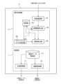
- FIG. It is a functional block diagram of the signal processing device in the same embodiment.
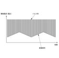
- FIG. 4 is a diagram showing drive current (voltage) and modulation signal in pseudo continuous oscillation;
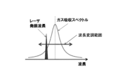
- FIG. 4 is a schematic diagram showing a method of modulating a laser oscillation wavelength in the same embodiment;
- 5 is a time-series graph showing an example of oscillation wavelength, light intensity I(t), logarithmic intensity L(t), feature signal F i (t), and correlation value S i (t) in the same embodiment.
- FIG. 4 is a diagram showing drive current (voltage) and modulation signal in pseudo continuous oscillation
- FIG. 4 is a schematic diagram showing a method of modulating a laser oscillation wavelength in the same embodiment
- 5 is a time-series graph showing an example of oscillation wavelength, light intensity I(t), logarithmic intensity L(t), feature signal F i (t), and correlation value S i (t)
- FIG. 4 is a diagram showing wavelength shift and modulation width shift in an intensity-related signal (absorption signal); 4 is a graph showing (a) wavelength correction relational data and (b) modulation correction relational data in the same embodiment. 4 is a lookup table showing (a) wavelength correction relational data and (b) modulation correction relational data in the same embodiment.
- FIG. 10 is a diagram showing a conceptual diagram of concentration calculation using a single correlation value and a measured correlation value in the same embodiment; It is a functional block diagram of a signal processing device in a modified embodiment.
- FIG. 11 is an overall schematic diagram of an analysis device according to a modified embodiment;
- FIG. 4 is a schematic diagram showing spectral changes due to coexistence effects and spectral changes due to pressure changes;
- the analysis device 100 of the present embodiment is a concentration measurement device that measures the concentration of a measurement target component contained in a combustion gas such as a combustion gas or a combustion exhaust gas, or a sample gas such as a process gas.
- a combustion gas such as a combustion gas or a combustion exhaust gas
- a sample gas such as a process gas.
- the gas being burned is the gas being burned in an internal combustion engine such as an automobile, an external combustion engine, an industrial furnace, an incinerator, a turbine, or a power plant, etc.
- the combustion exhaust gas is an internal combustion engine such as an automobile, It is a post-combustion gas discharged from an external combustion engine, an industrial furnace, an incinerator, a turbine, or a power plant.
- Process gas refers to gas in chemical plants such as petrochemical, coal chemical, natural gas chemical, petroleum refining, methanation, and gasification furnaces. It includes gas or gas produced in a chemical plant.
- the analyzer 100 of the present embodiment is connected to an introduction channel for introducing a sampling gas into the analyzer 100, and is also connected to a discharge channel for discharging the gas analyzed by the analyzer 100. It is A pump for introducing the sampling gas into the analyzer 100 is provided in the introduction channel or the discharge channel.
- the introduction channel may be configured to directly sample the exhaust gas from an exhaust pipe or the like, or may be configured to introduce the exhaust gas from a bag in which the exhaust gas is collected. It may be configured to introduce exhaust gas diluted by a dilution device such as a volume sampler.
- the cell 1 is made of a transparent material such as quartz, calcium fluoride, barium fluoride, etc., which hardly absorbs light in the absorption wavelength band of the component to be measured, and has a light entrance and a light exit. Although not shown, the cell 1 is provided with an inlet port for introducing gas into the interior and an outlet port for discharging the internal gas. introduced into a transparent material such as quartz, calcium fluoride, barium fluoride, etc., which hardly absorbs light in the absorption wavelength band of the component to be measured, and has a light entrance and a light exit. Although not shown, the cell 1 is provided with an inlet port for introducing gas into the interior and an outlet port for discharging the internal gas. introduced into a transparent material such as quartz, calcium fluoride, barium fluoride, etc., which hardly absorbs light in the absorption wavelength band of the component to be measured, and has a light entrance and a light exit. Although not shown, the cell 1 is provided with an inlet port for introducing gas into
- the semiconductor laser 2 here is a quantum cascade laser (QCL), which is a type of semiconductor laser 2, and oscillates mid-infrared (4 to 12 ⁇ m) laser light.
- QCL quantum cascade laser
- This semiconductor laser 2 is capable of modulating (changing) the oscillation wavelength by a given current (or voltage). Note that other types of lasers may be used as long as the oscillation wavelength is variable, and the temperature may be changed to change the oscillation wavelength.
- the temperature controller 3 adjusts the temperature of the semiconductor laser 2, and uses a thermoelectric conversion element such as a Peltier element.
- the temperature control unit 3 of the present embodiment has a semiconductor laser 2 and a temperature sensor (not shown) for detecting the temperature of the semiconductor laser 2 mounted on the heat absorption surface, which is the upper surface, and a temperature sensor (not shown) for detecting the temperature of the semiconductor laser 2.
- a heat sink (not shown) such as radiation fins is provided.
- the temperature control section 3 adjusts the temperature of the semiconductor laser 2 by controlling the applied DC voltage (DC current) according to a target temperature given by a temperature control control section 72 which will be described later.
- the temperature sensor 4 detects the ambient temperature of the semiconductor laser 2. Here, it detects the temperature in the atmosphere inside the package housing the semiconductor laser and the temperature control unit 3, or the ambient temperature outside the package. .
- the photodetector 5 here uses a thermal type such as a thermopile that is relatively inexpensive, but other types such as quantum type such as HgCdTe, InGaAs, InAsSb, or PbSe with good responsiveness are used.
- a photoelectric element may also be used.
- the signal processing device 6 includes at least one of an analog electric circuit consisting of a buffer, an amplifier, etc., a digital electric circuit consisting of a CPU, a memory, etc., and an AD converter, a DA converter, etc. that mediate between these analog/digital electric circuits.
- a control unit 7 for controlling the semiconductor laser 2 and the temperature control unit 3 as shown in FIG. also, it functions as a signal processing section 8 that receives an output signal from the photodetector 5 and calculates the concentration of the component to be measured by arithmetically processing the value.
- the control unit 7 has a light source control unit 71 that controls the oscillation and modulation width of the semiconductor laser 2 and a temperature control unit 72 that controls the temperature control unit 3 to a predetermined temperature.
- the light source control unit 71 controls a current source (or voltage source) that drives the semiconductor laser 2 by outputting a current (or voltage) control signal. Specifically, as shown in FIG. 3, the light source control unit 71 applies a drive current (or drive voltage) for wavelength modulation to a predetermined frequency, in addition to the drive current (or drive voltage) for causing the semiconductor laser 2 to pulse-oscillate. , and the oscillation wavelength of the laser light output from the semiconductor laser 2 is modulated at a predetermined frequency with respect to the center wavelength. As a result, the semiconductor laser 2 emits modulated light modulated at a predetermined modulation frequency.
- the light source control unit 71 changes the driving current in a triangular waveform, and modulates the oscillation wavelength in a triangular waveform (see “Oscillation wavelength" in FIG. 5).
- the driving current is modulated by another function so that the oscillation wavelength becomes triangular.
- the oscillation wavelength of the laser beam is modulated with the peak of the light absorption spectrum of the component to be measured as the central wavelength.
- the light source control unit 71 may change the drive current in a sine wave, sawtooth wave, or any function, and modulate the oscillation wavelength in a sine wave, sawtooth wave, or any function.
- the analyzer 100 detects nitrogen monoxide (NO), nitrogen dioxide (NO 2 ), nitrous oxide (N 2 O), ammonia (NH 3 ), ethane (C 2 H 6 ), formaldehyde in the combustion gas. (HCHO), acetaldehyde ( CH3CHO ) sulfur dioxide ( SO2 ), methane ( CH4 ), methanol ( CH3OH ) or ethanol ( C2H5OH ), when measuring the concentration of at least one of
- the light source controller 71 modulates the semiconductor laser 2 so that the wavelength modulation range is as follows.
- the semiconductor laser 2 is appropriately selected to emit modulated light modulated within the following wavelength modulation range.
- the light source control unit 71 sets the wavelength modulation range of the laser light to include wavelengths between 5.24 and 5.26 ⁇ m. modulate. Specifically, the light source control unit 71 modulates the wavelength modulation range of the laser light so as to preferably include a wavelength of 5.245 to 5.247 ⁇ m, more preferably a wavelength of 5.2462 ⁇ m. Such modulation can reduce the interfering effects of water (H 2 O), carbon dioxide (CO 2 ) and/or ethylene (C 2 H 4 ) and low concentrations of nitric oxide (NO). can improve the measurement accuracy of the concentration of
- the light source control unit 71 adjusts the wavelength modulation range of the laser light to include wavelengths between 6.14 and 6.26 ⁇ m. modulate. Specifically, the light source control unit 71 modulates the wavelength modulation range of the laser light so that it preferably includes a wavelength of 6.145 to 6.254 ⁇ m, more preferably a wavelength of 6.2322 ⁇ m or 6.2538 ⁇ m. . Such modulation can reduce the interfering effects of water (H 2 O) and/or ammonia (NH 3 ) and improve the measurement accuracy of low-concentration nitrogen dioxide (NO 2 ) concentrations. can be done.
- modulation can reduce the interfering effects of water (H 2 O) and/or ammonia (NH 3 ) and improve the measurement accuracy of low-concentration nitrogen dioxide (NO 2 ) concentrations. can be done.
- the light source control unit 71 sets the wavelength modulation range of the laser light to include wavelengths between 7.84 and 7.91 ⁇ m. modulate as follows. Specifically, the light source control unit 71 sets the wavelength modulation range of the laser light to 7, preferably a wavelength between 7.845 and 7.907, more preferably 7.8455 ⁇ m, 7.8509 ⁇ m, 7.8784 ⁇ m, or 7.8455 ⁇ m, 7.8509 ⁇ m, and 7.8784 ⁇ m. Modulate to include the wavelength of 9067 ⁇ m.
- Such modulation can reduce the interfering effects of water (H 2 O), methane (CH 4 ) and/or acetylene (C 2 H 2 ) and low concentrations of nitrous oxide (N 2 O). ) can improve the measurement accuracy of the concentration.
- the light source control unit 71 modulates the wavelength modulation range of the laser light so as to include wavelengths between 9.38 and 9.56 ⁇ m.
- the light source control unit 71 modulates the wavelength modulation range of the laser light so that it preferably includes a wavelength between 9.384 and 9.557 ⁇ m, more preferably a wavelength of 9.3847 ⁇ m or 9.5566 ⁇ m. .
- the interfering effects of water ( H2O ), carbon dioxide ( CO2 ) and/or ethylene ( C2H4 ) can be reduced, and low concentrations of ammonia ( NH3 ) can be reduced . Concentration measurement accuracy can be improved.
- the light source controller 71 sets the wavelength modulation range of the laser light to include wavelengths between 3.33 and 3.36 ⁇ m. modulate to Specifically, the light source control unit 71 determines that the wavelength modulation range of the laser light is preferably a wavelength between 3.336 and 3.352 ⁇ m, more preferably a wavelength of 3.3368 ⁇ m, 3.3482 ⁇ m, or 3.3519 ⁇ m. is modulated to include Such modulation can reduce the interfering effects of water (H 2 O), methane (CH 4 ) and/or ethylene (C 2 H 4 ), and low concentrations of ethane (C 2 H 6 ). can improve the measurement accuracy of the concentration of
- the light source control unit 71 modulates the wavelength modulation range of the laser light so as to include wavelengths between 5.65 and 5.67 ⁇ m. . Specifically, the light source control unit 71 modulates the wavelength modulation range of the laser light so as to preferably include a wavelength between 5.651 and 5.652, more preferably a wavelength of 5.6514 ⁇ m. Such modulation can reduce the interfering effects of water (H 2 O) and/or ammonia (NH 3 ) and improve the measurement accuracy of low-concentration formaldehyde (HCHO) concentrations. . In addition, since these wavelengths also coincide with the strong absorption band of acetaldehyde (CH 3 CHO), simultaneous measurement of formaldehyde (HCHO) and acetaldehyde (CH 3 CHO) is possible.
- HCHO acetaldehyde
- the light source control unit 71 can also modulate the wavelength modulation range of the laser light so as to preferably include a wavelength between 5.665 and 5.667 ⁇ m, more preferably a wavelength of 5.6660 ⁇ m.
- the absorption intensity of formaldehyde (HCHO) is slightly lower than the wavelength of 5.6514 ⁇ m, but the absorption intensity of water (H 2 O) is smaller, and their interference effects are smaller. As a result, the formaldehyde (HCHO) concentration measurement accuracy can be improved.
- This wavelength also coincides with the strong absorption band of acetaldehyde (CH 3 CHO), enabling measurement of acetaldehyde (CH 3 CHO) or simultaneous measurement of formaldehyde (HCHO) and acetaldehyde (CH 3 CHO).
- the light source control unit 71 adjusts the wavelength modulation range of the laser light to include wavelengths between 7.38 and 7.42 ⁇ m. modulate. Specifically, the light source control unit 71 preferably modulates the wavelength modulation range of the laser light to include a wavelength of 7.385 to 7.417 ⁇ m, more preferably a wavelength of 7.3856 ⁇ m or 7.4163 ⁇ m. .
- the light source control unit 71 modulates the wavelength modulation range of the laser light so as to include wavelengths between 7.50 and 7.54 ⁇ m.
- the light source control unit 71 modulates the wavelength modulation range of the laser light so as to preferably include a wavelength of 7.503 to 7.504 ⁇ m, more preferably a wavelength of 7.5035 ⁇ m.
- Such modulation can reduce the interfering effects of water ( H2O ), sulfur dioxide ( SO2 ), acetylene ( C2H2 ) and/or nitrous oxide ( N2O ), It is possible to improve the measurement accuracy of the low-concentration methane (CH 4 ) concentration.
- by modulating to include 7.5035 ⁇ m there is an absorption line of water (H 2 O) near this wavelength, and simultaneous measurement of methane (CH 4 ) and water (H 2 O) is possible. becomes.
- the light source control unit 71 can also modulate the wavelength modulation range of the laser light so as to preferably include a wavelength between 7.535 and 7.536 ⁇ m, more preferably a wavelength of 7.5354 ⁇ m.
- the absorption intensity of methane (CH 4 ) is almost equivalent to the wavelength of 7.5035 ⁇ m above, and the interference components in the combustion gas in this wavelength range are water (H 2 O), sulfur dioxide (SO 2 ), acetylene ( C 2 H 2 ) and/or nitrous oxide (N 2 O) have smaller absorption intensities and their interfering effects are smaller. As a result, it is possible to improve the measurement accuracy of the concentration of methane (CH 4 ).
- the light source control unit 71 adjusts the wavelength modulation range of the laser light to include wavelengths between 9.45 and 9.47 ⁇ m. modulate. Specifically, the light source control unit 71 modulates the wavelength modulation range of the laser light so as to preferably include a wavelength between 9.467 and 9.468 ⁇ m, more preferably a wavelength of 9.4671 ⁇ m. By modulating in this way, the interfering effects of ethylene ( C2H4 ), ammonia ( NH3 ) and/or carbon dioxide ( CO2 ) can be reduced, and low concentrations of methanol ( CH3OH ) can be reduced. Concentration measurement accuracy can be improved. These wavelengths also coincide with the strong absorption band of ethanol (C 2 H 5 OH), allowing simultaneous measurement of methanol (CH 3 OH) and ethanol (C 2 H 5 OH).
- the light source control unit 71 can also modulate the wavelength modulation range of the laser light so as to preferably include a wavelength between 9.455 and 9.456 ⁇ m, more preferably a wavelength of 9.4557 ⁇ m.
- ethylene (C 2 H 4 ) which has an absorption intensity of methanol (CH 3 OH) or ethanol (C 2 H 5 OH) approximately equivalent to the above 9.4671 ⁇ m, and is an interference component in the combustion gas in this wavelength region; Ammonia (NH 3 ) and/or carbon dioxide (CO 2 ) have lower absorption intensities and their interference effects are smaller.
- NH 3 methanol
- CO 2 carbon dioxide
- the analyzer 100 detects carbon dioxide (CO 2 ), carbon monoxide (CO), ethylene (C 2 H 4 ), ammonia (NH 3 ), ethane (C 2 H 6 ), water (H 2 O), acetylene (C 2 H 2 ), methane (CH 4 ), ammonia (NH 3 ), and methanol (CH 3 OH).
- the semiconductor laser 2 is modulated within the wavelength modulation range.
- the light source control unit 71 adjusts the wavelength modulation range of the laser light to include wavelengths between 4.23 and 4.24 ⁇ m. modulate. Specifically, the light source control unit 71 preferably controls the wavelength modulation range of the laser light to be between 4.234 ⁇ m and 4.238 ⁇ m, or between 4.235 ⁇ m and 4.238 ⁇ m, more preferably between 4.2347 ⁇ m and 4.2347 ⁇ m. Modulate to include the wavelength of 2371 ⁇ m.
- the light source control unit 71 determines that the wavelength modulation range of the laser light includes wavelengths between 4.34 and 4.35 ⁇ m. modulate as follows. Specifically, the light source control unit 71 modulates the wavelength modulation range of the laser light so that it preferably includes a wavelength between 4.342 and 4.347 ⁇ m, more preferably a wavelength of 4.3428 ⁇ m or 4.3469 ⁇ m. .
- the light source control unit 71 sets the wavelength modulation range of the laser light between 4.59 and 4.61 ⁇ m, or between 4.59 and 4.59 ⁇ m. 4. Modulate to include the 60 ⁇ m wavelength. Specifically, the light source control unit 71 modulates the wavelength modulation range of the laser light so that it preferably includes a wavelength between 4.594 and 4.604 ⁇ m, more preferably a wavelength of 4.5950 ⁇ m or 4.6024 ⁇ m. .
- the light source control unit 71 adjusts the wavelength modulation range of the laser light to include wavelengths between 5.89 and 6.12 ⁇ m. modulate. Specifically, the light source control unit 71 preferably modulates the wavelength modulation range of the laser light to include a wavelength of 5.896 to 5.934 ⁇ m, more preferably 5.8965 ⁇ m or 5.9353 ⁇ m. .
- the light source control unit 71 modulates the wavelength modulation range of the laser light so as to preferably include a wavelength of 6.046 to 6.114 ⁇ m, more preferably a wavelength of 6.0486 ⁇ m or 6.1138 ⁇ m. can also By modulating in this way, the interfering effects of methane ( CH4 ), ethylene ( C2H4 ) and/or ethane ( C2H6 ) can be reduced, and high concentrations of methane ( CH4 ), The measurement accuracy of dilute water ( H2O ) concentrations in process gases containing ethylene ( C2H4 ) and/or ethane ( C2H6 ) can be improved.
- the light source control unit 71 sets the wavelength modulation range of the laser light between 7.56 ⁇ m and 7.66 ⁇ m. Modulate to include wavelengths between 7.81 ⁇ m, between 7.27-7.24 ⁇ m, or between 7.25-7.81 ⁇ m.
- the light source control unit 71 preferably determines that the wavelength modulation range of the laser light is between 7.378 and 7.638 ⁇ m, between 7.378 and 7.603 ⁇ m, between 7.378 and 7.420 ⁇ m, a wavelength between 7.430 and 7.603 ⁇ m, between 7.430 and 7.638 ⁇ m, between 7.629 and 7.683 ⁇ m, or between 7.594 and 7.651 ⁇ m, more preferably 7.5966 ⁇ m, Modulate to include wavelengths of 7.6233 ⁇ m or 7.6501 ⁇ m.
- the light source control unit 71 preferably controls the wavelength modulation range of the laser light to include wavelengths between 7.566 and 7.634 ⁇ m, more preferably 7.5698 ⁇ m, 7.6231 ⁇ m, or 7.6367 ⁇ m. It can also be modulated. By modulating in this way, the interfering effects of methane ( CH4 ), ethylene ( C2H4 ) and/or ethane ( C2H6 ) can be reduced, and high concentrations of methane ( CH4 ), The measurement accuracy of low concentrations of acetylene ( C2H2 ) in process gases containing ethylene ( C2H4 ) and/or ethane ( C2H6 ) can be improved.
- the light source control unit 71 modulates the wavelength modulation range of the laser light so as to include wavelengths between 7.67 and 7.80 ⁇ m.
- the light source control unit 71 preferably modulates the wavelength modulation range of the laser light so as to include a wavelength between 7.670 and 7.792 ⁇ m, more preferably a wavelength of 7.6704 ⁇ m or 7.7914 ⁇ m. .
- the interfering effects of ethylene ( C2H4 ) and/or ethane ( C2H6 ) can be reduced, and high concentrations of ethylene ( C2H4 ) and/or ethane ( C 2 H 6 ) can be used to improve the measurement accuracy of the concentration of low-concentration methane (CH 4 ) in the process gas.
- the light source controller 71 sets the wavelength modulation range of the laser light to include wavelengths between 8.10 and 8.14 ⁇ m. modulate to Specifically, the light source control unit 71 modulates the wavelength modulation range of the laser light so that it preferably includes a wavelength between 8.107 and 8.139, more preferably a wavelength of 8.1073 ⁇ m or 8.1381 ⁇ m. .
- the light source control unit 71 adjusts the wavelength modulation range of the laser light to include wavelengths between 8.10 and 8.13 ⁇ m. modulate. Specifically, the light source control unit 71 modulates the wavelength modulation range of the laser light so that it preferably includes a wavelength between 8.102 and 8.121, more preferably a wavelength of 8.1022 ⁇ m or 8.1206 ⁇ m. .
- the light source control unit 71 adjusts the wavelength modulation range of the laser light to include wavelengths between 8.10 and 8.13 ⁇ m. modulate. Specifically, the light source control unit 71 modulates the wavelength modulation range of the laser light so as to include the wavelength of 8.1022 ⁇ m or 8.1206 ⁇ m.
- the light source control unit 71 sets the wavelength modulation range of the laser light to include wavelengths between 8.46 and 8.60 ⁇ m. modulate as follows. Specifically, the light source control unit 71 preferably modulates the wavelength modulation range of the laser light to include a wavelength of 8.464 to 8.599 ⁇ m, more preferably a wavelength of 8.4647 ⁇ m or 8.5981 ⁇ m. .
- the interfering effects of methane ( CH4 ) and/or ethane ( C2H6 ) can be reduced, and high concentrations of methane ( CH4 ) and/or ethane ( C2H6 ) can be reduced .
- ) can be improved in measuring the concentration of high-concentration ethylene (C 2 H 4 ) in the process gas.
- the light source control unit 71 sets the wavelength modulation range of the laser light to 6.09 ⁇ m between 6.13 ⁇ m and 6.14 ⁇ m. Modulate to include wavelengths between ⁇ 6.45 ⁇ m, 6.09-6.39 ⁇ m, or 6.41 ⁇ m-6.45 ⁇ m. Specifically, the light source control unit 71 controls the wavelength modulation range of the laser light to be preferably between 6.135 ⁇ m and 6.139 ⁇ m, or between 6.463 ⁇ m and 6.619 ⁇ m, more preferably between 6.1384 ⁇ m and 6.1384 ⁇ m.
- the interfering effects of methane ( CH4 ) and/or ethylene ( C2H4 ) can be reduced, and high concentrations of methane ( CH4 ) and/or ethylene ( C2H4 ) can be reduced.
- ) can be improved in measuring the concentration of high-concentration ethane (C 2 H 6 ) in the process gas.
- the light source control unit 71 sets the wavelength modulation range of the laser light to between 6.06 and 6.25 ⁇ m. , 6.06-6.14 ⁇ m, 6.15-6.17 ⁇ m, 6.19-6.25 ⁇ m, or 8.62-9.09 ⁇ m.
- the light source control unit 71 preferably determines that the wavelength modulation range of the laser light is between 6.141 and 6.153 ⁇ m, between 6.141 and 6.149 ⁇ m, between 6.150 and 6.153 ⁇ m, or Modulated to include wavelengths between 8.939 and 8.968 ⁇ m, more preferably 6.1450 ⁇ m, 6.1487 ⁇ m, 6.1496 ⁇ m, 8.9604 ⁇ m, 8.9473 ⁇ m, or 8.7671 ⁇ m.
- the interfering effects of methane ( CH4 ) and/or ethylene ( C2H4 ) can be reduced, and high concentrations of methane ( CH4 ) and/or ethylene ( C2H4 ) can be reduced.
- the light source control unit 71 sets the wavelength modulation range of the laser light to include wavelengths between 9.35 and 9.62 ⁇ m. modulate as follows. Specifically, the light source control unit 71 determines that the wavelength modulation range of the laser light preferably includes a wavelength between 9.477 and 9.526 ⁇ m, more preferably a wavelength of 9.5168 ⁇ m, 9.5042 ⁇ m, or 9.4861 ⁇ m. modulate as follows.
- the temperature control section 72 controls the current source (or voltage source) of the temperature control section 3 by outputting a control signal for setting the temperature control section 3 to a predetermined target temperature. Thereby, the temperature control unit 3 controls the temperature of the semiconductor laser 2 to a predetermined target temperature.
- control unit 7 of the present embodiment uses a correction parameter P( ⁇ ) (FIG. 6 ), and modulation correction indicating the relationship between the ambient temperature and the correction parameter P( ⁇ w) for correcting the modulation width deviation of the semiconductor laser 2 (see FIG. 6).
- a relational data storage unit 73 for storing relational data is provided.
- the relational data for wavelength correction is shown in FIG. 7(a). It is generated by obtaining a certain target temperature change amount in advance by experiment or calculation.
- P( ⁇ ) is the target temperature change amount
- T0 is the reference temperature (for example, room temperature (25° C.))
- tk is the temperature at the ambient temperature T relative to the reference temperature T0 . This is a coefficient indicating the degree of influence of the target temperature change amount.
- the relational data for wavelength correction may be in formula form as shown in FIG. 7(a), or may be in lookup table form as shown in FIG. 8(a).
- the relation data for modulation correction is shown in FIG. 7(b). It is generated by obtaining a certain drive voltage (current) change amount in advance by experiment or calculation.
- P( ⁇ w) is the amount of change in the drive voltage (current)
- T 0 is the reference temperature (for example, room temperature (25° C.))
- v k is the ambient temperature relative to the reference temperature T 0 . This is a coefficient indicating the degree of influence of the amount of change in drive voltage (current) at temperature T.
- the modulation correction related data may be in the formula format as shown in FIG. 7(b) or in the lookup table format as shown in FIG. 8(b).
- the temperature control unit 72 also corrects the wavelength deviation of the semiconductor laser 2 by changing the target temperature of the temperature control unit 3 using the temperature detected by the temperature sensor 4 and the relationship data for wavelength correction.
- the light source control unit 71 also corrects the modulation width of the semiconductor laser 2 by changing the drive voltage or drive current of the semiconductor laser 2 using the temperature detected by the temperature sensor 4 and the relationship data for modulation correction. Specifically, the light source controller 71 corrects the modulation width by adjusting the amplitude or offset of the modulation voltage (modulation current) for modulating the wavelength.
- the signal processing unit 8 includes a logarithm calculation unit 81, a correlation value calculation unit 82, a storage unit 83, a wavelength shift determination unit 84, a density calculation unit 85, and the like.
- the logarithmic calculator 81 performs logarithmic calculation on the light intensity signal, which is the output signal of the photodetector 5 .
- the function I(t) representing the change over time of the light intensity signal obtained by the photodetector 5 becomes like the "light intensity I(t)" in FIG. logarithmic intensity L(t)".
- the correlation value calculator 82 calculates correlation values between an intensity-related signal related to the intensity of sample light and a plurality of predetermined feature signals.
- a feature signal is a signal for extracting a waveform feature of an intensity-related signal by taking a correlation with the intensity-related signal.
- the feature signal for example, a sine wave signal or various signals matching waveform features desired to be extracted from other intensity-related signals can be used.
- the correlation value calculator 82 calculates correlation values between an intensity-related signal related to the intensity of the sample light and a plurality of feature signals with which a correlation different from a sine wave signal (sine function) is obtained with respect to the intensity-related signal. Calculate Here, the correlation value calculator 82 uses the logarithmically calculated light intensity signal (logarithmic intensity L(t)) as the intensity-related signal.
- the correlation value calculator 82 calculates the correlation value Si It is desirable to calculate a corrected sample correlation value S′ i by subtracting a reference correlation value Ri , which is a correlation value between the intensity-related signal L 0 (t) of the reference light and the plurality of feature signals F i (t), from .
- Ri a correlation value between the intensity-related signal L 0 (t) of the reference light and the plurality of feature signals F i (t)
- the configuration may be such that the reference correlation value is not subtracted.
- the acquisition timing of the reference light is simultaneous with the sample light, before or after the measurement, or any timing.
- the reference light intensity-related signal or the reference correlation value may be acquired in advance and stored in the storage unit 83 .
- a method of obtaining reference light simultaneously is, for example, to provide two photodetectors 5, split the modulated light from the semiconductor laser 2 by a beam splitter or the like, and use one for sample light measurement and the other for reference. It is conceivable to use it for optical measurement.
- the correlation value calculator 82 uses, as the plurality of feature signals F i (t), a function that makes it easier to capture the waveform feature of the logarithmic intensity L(t) than a sine function.
- a function based on a Lorentzian function close to the shape of the absorption spectrum as shown in the following equation (Equation 2) and a function based on the Lorentzian function It is conceivable to use a partial differential function of the deviation from the reference time position.
- w is the Lorentz width
- s is the shift from the reference time position of the absorption peak due to wavelength shift
- A is an arbitrary constant
- a 1 , A 2 and A 3 are F 1 (t)
- This is an offset that adjusts F 2 (t) and F 3 (t) so that they become zero when integrated over the modulation period.
- a function based on the Voigt function, a function based on the Gaussian function, or the like can be used instead of the function based on the Lorentz function.
- the storage unit 83 stores the measurement obtained from each intensity-related signal and a plurality of feature signals F i (t) when the measurement target component and each interference component exist independently in the known wavelength shift amount of the reference light.
- a single correlation value which is a correlation value per unit concentration of each of the target component and each interference component, is stored.
- the plurality of feature signals F i (t) used to obtain this single correlation value are the same as the plurality of feature signals F i (t) used in the correlation value calculator 82 . In this manner, the storage unit 83 stores individual correlation values for each wavelength shift of various reference beams.
- the storage unit 83 subtracts the reference correlation value from the correlation value when the measurement target component and each interference component exist alone, and then performs correction for conversion per unit concentration. It is desirable to store a single correlation value that As a result, the offset included in the single correlation value is removed, and the correlation value becomes proportional to the concentrations of the measurement target component and the interfering component, thereby reducing measurement errors. Note that the configuration may be such that the reference correlation value is not subtracted.
- the wavelength shift determination unit 84 determines the wavelength shift amount W of the reference light from the light intensity signal, which is the output signal of the photodetector 5 .
- the following procedure can be considered.
- Each single correlation value s itar ( W k ) and s iint (W k ) are obtained in advance, and the sample correlation value obtained at the time of measurement and the single correlation value are compared and collated to determine the wavelength shift W of the reference light.
- Specific comparison and collation methods include, for example, the nonlinear least-squares method involving iterative calculation using the steepest descent method, the Gauss-Newton method, the Levenberg-Marquardt method, and the like.
- the number of required feature signals is equal to or greater than the sum of the number of types of measurement target components and the number of types of interference components plus one.
- the reason for adding 1 is to correspond to the amount of wavelength shift, which is a parameter common to the light absorption spectrum of each component.
- (b) Determine the wavelength shift amount W of the reference light using relational data indicating the relationship between the ambient temperature and the wavelength shift amount W and the measured ambient temperature.
- the relational data is generated in advance by obtaining the wavelength shift W of the reference light for each ambient temperature of the light source 2 by experiment or calculation.
- the concentration calculator 85 calculates the concentration of the component to be measured using the plurality of sample correlation values obtained by the correlation value calculator 82 .
- the concentration calculator 85 calculates the plurality of sample correlation values obtained by the correlation value calculator 82 , the wavelength shift amount W determined by the wavelength shift determiner 84 , and the plurality of independent values stored in the storage unit 83 .
- the concentration of the component to be measured is calculated based on the correlation value. More specifically, the density calculation unit 85 corrects and acquires the plurality of single correlation values stored in the storage unit 83 from the wavelength shift amount W obtained by the wavelength shift determination unit 84 . Then, the concentration calculation unit 85 calculates the plurality of sample correlation values obtained by the correlation value calculation unit 82, the corrected plurality of single correlation values corresponding to the determined wavelength shift amount W, the measurement target component and each interference. The concentration of the component to be measured is calculated by solving simultaneous equations consisting of the concentration of each component (see FIG. 9).
- the sample gas contains one component to be measured and one interfering component.
- the light source control unit 71 controls the semiconductor laser 2 to obtain the absorption spectrum of the component to be measured at a predetermined modulation frequency and modulation depth.
- the wavelength of the laser light is modulated around the peak of .
- the reference correlation value may be measured by performing the reference measurement using the zero gas.
- a span gas (a gas with a known component concentration) into the cell 1 to perform a reference measurement.
- This reference measurement is performed for each of a span gas in which the component to be measured exists alone and a span gas in which the interfering component alone exists.
- the logarithmic calculator 61 receives each output signal of the photodetector 5 for each wavelength shift amount of the reference light and calculates the logarithmic intensity L(t). Then, the correlation value calculator 82 calculates the correlation values between the logarithmic intensity L(t) and the three feature signals F 1 (t), F 2 (t), and F 3 (t), and from the correlation values By dividing the result obtained by subtracting the reference correlation value by the concentration of the span gas, a single correlation value, which is the correlation value of each span gas per unit concentration, is calculated. Instead of calculating the single correlation value, the relationship between the span gas concentration and the correlation value of the span gas may be stored.
- the correlation value calculator 82 calculates the correlation value S 1tar ( wk ) of the component to be measured. , S 2tar (w k ), S 3tar (w k ).
- S 1tar (w k ) is the correlation value with the first feature signal
- S 2tar (w k ) is the correlation value with the second feature signal
- S 3tar (w k ) is , is the correlation value with the third feature signal.
- the correlation value calculator 82 subtracts the reference correlation value Ri from the correlation values S 1tar (w k ), S 2tar (w k ), and S 3tar (w k ) to obtain the span gas concentration c of the component to be measured.
- the single correlation values s 1tar (w k ), s 2tar (w k ), s 3tar (w k ) are calculated. This procedure is performed by changing the set temperature of the semiconductor laser 2 while sequentially changing the amount of wavelength deviation of the reference light (for example, from ⁇ 0.01 cm ⁇ 1 to +0.01 cm ⁇ 1 in increments of 0.001 cm ⁇ 1 ) . ) for each wavelength shift amount, and the relationship between the obtained single correlation value for each wavelength shift amount and the wavelength shift is stored.
- the span gas concentration c tar of the component to be measured is input to the signal processing unit 8 in advance by a user or the like.
- the correlation value calculator 82 calculates the correlation value S1int ( wk ) of the interference component. , S 2int (w k ), and S 3int (w k ).
- S 1int (w k ) is the correlation value with the first feature signal
- S 2int (w k ) is the correlation value with the second feature signal
- S 3int (w k ) is , is the correlation value with the third feature signal.
- the correlation value calculator 82 subtracts the reference correlation value Ri from the correlation values S 1int (w k ), S 2int (w k ), and S 3int (w k ) to obtain the span gas concentration c int of the interference component. to calculate the single correlation values s 1int (w k ), s 2int (w k ), s 3int (w k ).
- This procedure is performed by changing the set temperature of the semiconductor laser 2 while sequentially changing the amount of wavelength deviation of the reference light (for example, from ⁇ 0.01 cm ⁇ 1 to +0.01 cm ⁇ 1 in increments of 0.001 cm ⁇ 1 ) . ) for each wavelength shift amount, and the relationship between the obtained single correlation value for each wavelength shift amount and the wavelength shift amount is stored.
- the span gas concentration c int of the interference component is input to the signal processing unit 8 in advance by a user or the like.
- Single correlation values s 1tar (w k ), s 2tar (w k ) , s 3tar (w k ), s 1int (w k ), s 2int (w k ) and s 3int (w k ) are stored in the storage unit 83 . Note that this reference measurement may be performed before product shipment, or may be performed periodically.
- the light source controller 71 controls the semiconductor laser 2 to modulate the wavelength of the laser light with a predetermined modulation frequency and modulation depth centering on the peak of the absorption spectrum of the component to be measured.
- the temperature control section 72 changes the target temperature of the temperature control section 3 using the detected temperature and the wavelength correction relationship data obtained by the temperature sensor 4 to correct the wavelength deviation of the semiconductor laser 2 .
- the light source control unit 71 also corrects the modulation width of the semiconductor laser 2 by changing the drive voltage or drive current of the semiconductor laser 2 using the temperature detected by the temperature sensor 4 and the relationship data for modulation correction.
- a sample gas is then introduced into the cell 1 by an operator or automatically, and a sample measurement is performed.
- the logarithmic calculator 81 receives the output signal of the photodetector 3 and calculates the logarithmic intensity L(t). Then, the correlation value calculator 82 calculates sample correlation values S 1 , S 2 , S between the logarithmic intensity L(t) and the plurality of feature signals F 1 (t), F 2 (t), F 3 (t). 3 is calculated, and sample correlation values S' 1 and S' 2 are calculated by subtracting the reference correlation value R i from the correlation value.
- the wavelength shift determination unit 84 determines the wavelength shift amount W by the method described above.
- the concentration calculator 85 calculates the wavelength shift amount W Determine the single correlation values s' 1tar , s' 2tar , s' 1int , s' 2int of the measured component and the interfering component corrected by .
- a method of determination for example, a method using linear interpolation, quadratic interpolation, spline interpolation, or the like can be considered.
- the density calculation unit 85 calculates the sample correlation values S′ 1 and S′ 2 corrected by the reference correlation values calculated by the correlation value calculation unit 82, and the corrected single correlation values s′ 1tar , s′ 2tar and s′ 1int . , s′ 2int , and the concentrations C tar and C int of the component to be measured and each interfering component, respectively (see FIG. 9).
- Equation 4 By solving the n-dimensional simultaneous equations represented by this equation (Equation 4), it is possible to determine the concentration corrected for the interference effects of each gas of the measurement target component and the interfering component. Note that even if the sample does not contain any interfering components, it is possible to determine the concentration corrected for the interference effects of each gas of the measurement target component and the interfering component by solving the above n-dimensional simultaneous equations. can.
- the temperature sensor 4 for detecting the temperature around the laser light source 2 detects the temperature around the laser light source 2 using the first relationship data indicating the relationship between the ambient temperature of the laser light source 2 and the parameter for correcting the wavelength deviation of the laser light source 2. Since the target temperature of the temperature control unit 3 is changed from the temperature, it is possible to reduce changes in the oscillation wavelength of the laser light source due to changes in the ambient temperature. As a result, the change in the absorption spectrum due to the change in the laser light source can be reduced without using a reference cell filled with a reference gas, and the concentration of the component to be measured can be accurately measured.
- the wavelength shift amount W of the reference light is determined by calculation, and the determined wavelength shift amount W is used to further correct the influence of the wavelength shift of the reference light. Since the concentration of the component to be measured is calculated, the change in the light absorption spectrum of the component to be measured caused by the wavelength shift of the reference light, which cannot be suppressed by physical wavelength shift correction, is corrected, and the concentration of the component to be measured is measured with even higher accuracy. can do.
- the logarithmic intensity L(t), which is an intensity-related signal related to the intensity of the sample light, and the plurality of characteristic signals F i (t) for the logarithmic intensity L(t) ), and the concentration of the component to be measured is calculated using the plurality of calculated correlation values Si .
- the concentration of the component to be measured can be measured with simple calculations without complicated spectral calculations. For example, several hundred data points are required for general spectrum fitting, but in the present invention, at most several to several tens of correlation values can be used to calculate concentrations with equivalent accuracy.
- the load of arithmetic processing can be dramatically reduced, an advanced arithmetic processing device becomes unnecessary, the cost of the analysis device 100 can be reduced, and the size can be reduced.
- the plurality of feature signals use signals that can obtain a correlation different from that of the sine wave signal, the accuracy is equal to or higher than that of an analyzer that performs concentration calculation by a method using conventional lock-in detection. It is possible to determine the concentration of the component to be measured.
- the logarithmic calculator 61 in each of the above-described embodiments logarithmically calculates the light intensity signal of the photodetector 3.
- the intensity of the sample light and the reference light It is also possible to calculate the logarithm (so-called absorbance) of the ratio to the intensity of the modulated light.
- the logarithmic calculator 61 may calculate the logarithm of the intensity of the sample light, calculate the logarithm of the intensity of the reference light, and then subtract them to calculate the absorbance. After obtaining the ratio of the intensity of , the absorbance may be calculated by taking the logarithm of the ratio.
- the correlation value calculator 62 in each of the above embodiments calculates the correlation value between the intensity-related signal and the feature signal, but instead calculates the inner product value of the intensity-related signal and the feature signal. good too.
- the signal processing unit 8 of the analyzer 100 determines a broadening factor that indicates the rate of change in the optical absorption spectrum of the component to be measured or the interference component caused by the coexisting component contained in the sample.
- a lighting factor determination unit 86 is provided.
- the broadening factor determining section 86 determines a broadening factor FB that indicates the change rate of the light absorption spectra of the measurement target component and the interference component caused by the coexisting components contained in the sample. If the coexistence effect of the coexisting component on the interference component should also be considered, the broadening factor FB is added and determined for each component.
- each single correlation value s itar ( p k ) and s iint (p k ) are obtained in advance, and the sample correlation value obtained at the time of measurement and the single correlation value are compared and collated to determine the broadening factor F B .
- the single correlation value is converted and used using the pressure value in the cell and the relationship of the following formula (Equation 5).
- the number of required feature signals is equal to or greater than the sum of the number of types of components to be measured, the number of types of interference components, and the number of types of broadening factors.
- p is the sample pressure measured by the pressure sensor 7
- F B is the broadening factor determined by the broadening factor determination unit 86
- sij is the single correlation value at each pressure stored in the storage unit 63.
- s' ij is the corrected single correlation value. Note that the above formula (Equation 5) is obtained by multiplying the single correlation value s ij (p) at the pressure p of the sample at the time of sample measurement by 1/FB times the single correlation value at the pressure obtained by multiplying the pressure by FB . indicates that the corrected single correlation value s' ij is obtained. If the interference component is also affected by broadening due to the coexisting component, the broadening factor of the interference component may be determined separately to correct the single correlation value of the interference component. This makes it possible to further improve the measurement accuracy.
- the broadening factor FB is determined using the relationship data indicating the relationship between the concentration of the coexisting component and the broadening factor FB and the measured concentration of the coexisting component.
- the relational data is generated in advance by determining the broadening factor FB for each concentration of the coexisting component by experiment or calculation.
- the measured concentrations of the coexisting components may be those measured by the analyzer 100 of the present embodiment before coexistence influence correction, or the concentrations of the coexisting components may be measured using another analyzer.
- the concentration calculator 65 calculates the concentration of the component to be measured using the plurality of sample correlation values obtained by the correlation value calculator 62 .
- the density calculation unit 65 calculates the plurality of sample correlation values obtained by the correlation value calculation unit 62, the broadening factor FB determined by the broadening factor determination unit 64, and the plurality of correlation values stored in the storage unit 63.
- the concentration of the component to be measured is calculated based on the single correlation value of .
- the density calculator 65 corrects and acquires the plurality of single correlation values stored in the storage 63 from the broadening factor FB obtained by the broadening factor determiner 64 .
- the concentration calculation unit 65 calculates the plurality of sample correlation values obtained by the correlation value calculation unit 62, the corrected plurality of single correlation values corresponding to the determined broadening factor FB , the component to be measured, and each The concentration of the component to be measured is calculated by solving simultaneous equations consisting of the concentrations of the interfering components.
- the concentration calculator 65 calculates the single correlation value for the pressure p k in each cell stored in the storage unit 63, the pressure value p in the cell measured by the pressure sensor 7, and the broadening factor determination unit Using the broadening factor F B determined by 64 and the above equation (Equation 5), the single correlation values s′ 1tar , s′ of the component to be measured corrected for both the pressure in the cell and the broadening factor 2tar and the single correlation values s' 1int and s' 2int of the interference components corrected only for the pressure in the cell (assuming a broadening factor of 1).
- a method of determination for example, a method using linear interpolation, quadratic interpolation, spline interpolation, or the like can be considered.
- the density calculation unit 65 calculates the sample correlation values S′ 1 and S′ 2 corrected by the reference correlation values calculated by the correlation value calculation unit 62, and the corrected single correlation values s′ 1tar , s′ 2tar and s′. Solve the following simultaneous binary equations consisting of 1 int , s′ 2 int and the concentrations C tar , C int of the component to be measured and the interfering component, respectively.
- the concentration C tar of the component to be measured from which the interference effect and the coexistence effect have been removed can be determined by a simple and reliable calculation of solving the simultaneous equations of the above equation (Equation 6).
- the modulation width correction of the laser light source 2 of the present invention can suppress changes in the modulation width of the laser light source due to changes in the ambient temperature, and correct broadening due to coexistence effects. can be measured with higher accuracy.
- the analysis device 100 may include a plurality of laser light sources 2 for irradiating the cells 2 with laser light and a plurality of temperature control units 3 corresponding thereto.
- the plurality of laser light sources 2 correspond to, for example, the measurement target components exemplified in the above embodiments.
- the plurality of laser light sources 2 are pulse-oscillated by the light source control unit 71 with the same oscillation cycle and different oscillation timings.
- the control contents of the light source control section 71 and the temperature control section 72 for each laser light source 2 and each temperature control section 3 are the same as in the above embodiment.
- the signal processing device 6 separates the signal of each of the plurality of laser light sources 2 from the light intensity signal obtained by the photodetector 5 , and uses the separated light absorption signal of each laser light source 2 to generate a signal for each laser light source 2 . Calculate the concentration of the corresponding component to be measured. Calculation of the concentration of the component to be measured by the signal processing unit 8 is the same as in the above embodiment.
- the wavelength shift is corrected physically and the wavelength shift is corrected by calculation, but the wavelength shift may not be corrected by calculation.
- the wavelength shift may be corrected by calculation without physically correcting the wavelength shift, or the wavelength shift may be corrected by calculation without physically correcting the wavelength shift.
- the modulation width deviation may not be corrected.
- the storage unit 83 stores the single correlation value corrected using the reference correlation value.
- the unit 83 may be configured to subtract the reference correlation value from the uncorrected single correlation value and then obtain the corrected single correlation value converted per unit density.
- the plurality of feature signals are not limited to the above embodiment, and may be different functions. Further, as the feature signal, for example, a function indicating a waveform (sample spectrum) of light intensity, logarithmic intensity, or absorbance obtained by flowing a span gas of known concentration may be used. Also, when measuring the concentration of one component to be measured, at least one characteristic signal is sufficient.
- the number of single correlation values and sample correlation values larger than the number of gas kinds is obtained using feature signals of more than n kinds, It is also possible to create simultaneous equations with a greater number of elements than the number of gas species, and determine the concentration of each component by the least squares method. Become.
- the signal processing unit of the embodiment uses an intensity-related signal related to the intensity of the sample light and a feature signal that provides a predetermined correlation with the intensity-related signal to obtain a concentration-dependent measurement of the component to be measured. function of the correlation value calculation unit for calculating the correlation value and the concentration calculation unit for calculating the concentration of the component to be measured using the correlation value obtained by the correlation value calculation unit. may be used.
- the light source is not limited to a semiconductor laser, but may be any other type of laser, or any light source that is a single-wavelength light source that has a sufficient half-value width to ensure measurement accuracy and that can be wavelength-modulated. may
- the concentration of at least one of carbon dioxide, carbon monoxide, ethylene, ethane, water, acetylene, methane, ammonia, and methanol in process gas can be measured with high accuracy.
Abstract
The present invention is for precisely measuring the concentration of a component to be measured in a processed gas. According to the present invention, the concentration of carbon dioxide is calculated on the basis of absorption at 4.23-4.24 μm or 4.34-4.35 μm by carbon dioxide, the concentration of carbon monoxide is calculated on the basis of absorption at 4.59-4.61 μm by carbon monoxide, the concentration of water is calculated on the basis of absorption at 5.89-6.12 μm by water, the concentration of acetylene is calculated on the basis of absorption at 7.56-7.66 μm or 7.27-7.81 μm by acetylene, the concentration of methane is calculated on the basis of absorption at 7.67-7.80 μm or 8.10-8.14 μm by methane, the concentration of ethylene is calculated on the basis of absorption at 8.46-8.60 μm by ethylene, the concentration of ethane is calculated on the basis of absorption at 6.13-6.14 μm or 6.09-6.45 μm by ethane, the concentration of ammonia is calculated on the basis of absorption at 6.06-6.25 μm or 8.62-9.09 μm by ammonia, and the concentration of methanol is calculated on the basis of absorption at 9.35-9.62 μm by methanol.
Description
本発明は、例えばガスの成分分析等に用いられる分析装置等に関するものである。
The present invention relates to analyzers and the like used for, for example, component analysis of gas.
化学プラントに使用される天然ガス等を含むプロセスガスの二酸化炭素(CO2)、一酸化炭素(CO)、エチレン(C2H4)、エタン(C2H6)、水(H2O)、アセチレン(C2H2)、メタン(CH4)、アンモニア(NH3)、メタノール(CH3OH)の少なくとも1つである測定対象成分を測定する場合には、プロセスガスに含まれる測定対象成分以外の干渉成分により測定誤差が生じる。具体的には、上記の測定対象成分の吸収ピーク位置に干渉成分の吸収スペクトルが重なってしまい、濃度定量に誤差が生じてしまう。
Carbon dioxide (CO 2 ), carbon monoxide (CO), ethylene (C 2 H 4 ), ethane (C 2 H 6 ), water (H 2 O) of process gases including natural gas used in chemical plants , acetylene (C 2 H 2 ), methane (CH 4 ), ammonia (NH 3 ), and methanol (CH 3 OH). Interference components other than the component cause measurement errors. Specifically, the absorption spectrum of the interfering component overlaps the absorption peak position of the component to be measured, resulting in an error in concentration determination.
一方で、測定対象成分に対する干渉成分の干渉影響を補正するものとしては、特許文献1に示すものが考えられている。
On the other hand, the method shown in Patent Document 1 is considered as a method for correcting the interference effect of the interference component on the component to be measured.
しかしながら、特許文献1の分析装置を用いる場合においても、プロセスガス中の測定対象成分に対する干渉影響をより効果的に低減するためには、適切な測定対象成分の吸収が存在する波長範囲を測定に用いる必要がある。その波長範囲の選択には、HITRANなどの公開されている赤外吸収スペクトルのデータベースを用いてある程度の予備検討は可能であるが、データベースを利用できるガス種や波長範囲は限定的であり、実際に測定対象ガスおよび干渉ガスによる実験を繰り返すことで初めて可能となる。また同じ測定対象成分でも、その濃度・圧力・温度や共存する干渉ガスの種類や濃度レンジによって、適切な波長範囲は異なる。特許文献1の分析装置では、干渉影響をより効果的に低減するための適切な波長範囲については考慮しておらず、これだけでは測定対象成分に対する干渉影響を効果的に除去できるとは言い難い。
However, even in the case of using the analysis apparatus of Patent Document 1, in order to more effectively reduce the interference effect on the measurement target component in the process gas, the wavelength range in which the measurement target component appropriately absorbs is used for measurement. need to use. For the selection of the wavelength range, it is possible to some degree of preliminary examination using a database of infrared absorption spectra that has been published such as HITRAN. It is possible only by repeating the experiment with the measurement target gas and the interfering gas. Moreover, even for the same component to be measured, the appropriate wavelength range differs depending on its concentration, pressure, temperature, and the type and concentration range of coexisting interference gases. The analysis apparatus of Patent Document 1 does not consider an appropriate wavelength range for more effectively reducing the interference effect, and it is difficult to say that this alone can effectively remove the interference effect on the measurement target component.
そこで、本発明は上述したような問題に鑑みてなされたものであり、プロセスガス中の二酸化炭素(CO2)、一酸化炭素(CO)、エチレン(C2H4)、エタン(C2H6)、水(H2O)、アセチレン(C2H2)、メタン(CH4)、アンモニア(NH3)、メタノール(CH3OH)の少なくとも1つである測定対象成分の濃度に対する干渉影響をより効果的に低減して、精度良く測定することをその主たる課題とするものである。
Therefore, the present invention has been made in view of the above-described problems, and is intended to eliminate carbon dioxide (CO 2 ), carbon monoxide (CO), ethylene (C 2 H 4 ), ethane (C 2 H 4 ), and ethane (C 2 H 4 ) in the process gas. 6 ), water ( H2O ), acetylene ( C2H2 ), methane ( CH4 ), ammonia ( NH3 ), and methanol ( CH3OH ). The main object is to effectively reduce the .
すなわち、本発明に係る分析装置は、プロセスガス中の二酸化炭素、一酸化炭素、エチレン、エタン、水、アセチレン、メタン、アンモニア、メタノールの少なくとも1つである測定対象成分の濃度を測定するものであって、前記プロセスガスに参照光を照射するレーザ光源と、前記参照光が前記プロセスガスを透過したサンプル光の強度を検出する光検出器と、前記光検出器の出力信号に基づいて、前記測定対象成分の濃度を算出する濃度算出部とを備え、前記濃度算出部は、前記二酸化炭素の濃度を測定する場合には、4.23~4.24μmの間、又は4.34~4.35μmの間の二酸化炭素の吸収に基づいて濃度を算出し、前記一酸化炭素の濃度を測定する場合には、4.59~4.61μmの間の一酸化炭素の濃度を算出し、前記水の濃度を測定する場合には、5.89~6.12μmの間の水の濃度を算出し、前記アセチレンの濃度を測定する場合には、7.56~7.66μmの間、又は7.27~7.81μmの間のアセチレンの濃度を算出し、前記メタンの濃度を測定する場合には、7.67~7.80μmの間、又は8.10~8.14μmの間のメタンの濃度を算出し、前記エチレンの濃度を測定する場合には、8.46~8.60μmの間のエチレンの濃度を算出し、前記エタンの濃度を測定する場合には、6.13~6.14μmの間、又は6.09~6.45μmの間のエタンの濃度を算出し、前記アンモニアの濃度を測定する場合には、6.06~6.25μmの間、又は8.62~9.09μmの間のアンモニアの吸収に基づいて濃度を算出し、前記メタノールの濃度を測定する場合には、9.35~9.62μmの間のメタノールの吸収に基づいて濃度を算出することを特徴とする。
That is, the analyzer according to the present invention measures the concentration of at least one of carbon dioxide, carbon monoxide, ethylene, ethane, water, acetylene, methane, ammonia, and methanol to be measured in process gas. a laser light source for irradiating the process gas with reference light; a photodetector for detecting intensity of sample light transmitted through the process gas by the reference light; and a concentration calculation unit for calculating the concentration of the component to be measured, wherein the concentration calculation unit is between 4.23 and 4.24 μm, or between 4.34 and 4.0 μm when measuring the concentration of the carbon dioxide. When the concentration is calculated based on the absorption of carbon dioxide between 35 μm and the concentration of carbon monoxide is measured, the concentration of carbon monoxide between 4.59 and 4.61 μm is calculated, and the water When measuring the concentration of , calculate the concentration of water between 5.89 and 6.12 μm, and when measuring the concentration of acetylene, between 7.56 and 7.66 μm, or 7. When calculating the concentration of acetylene between 27 and 7.81 μm and measuring the concentration of methane, the concentration of methane between 7.67 and 7.80 μm or between 8.10 and 8.14 μm When measuring the concentration of ethylene, calculate the concentration of ethylene between 8.46 and 8.60 μm, and when measuring the concentration of ethane, 6.13 to 6.14 μm or between 6.09 and 6.45 μm, and when measuring the concentration of ammonia, between 6.06 and 6.25 μm, or between 8.62 and 9.09 μm The concentration is calculated based on the absorption of ammonia between 9.35 and 9.62 μm. .
この分析装置であれば、プロセスガス中の二酸化炭素(CO2)、一酸化炭素(CO)、エチレン(C2H4)、エタン(C2H6)、水(H2O)、アセチレン(C2H2)、メタン(CH4)、アンモニア(NH3)、メタノール(CH3OH)の少なくとも1つである測定対象成分の濃度を精度良く測定することができる。詳細は後述する。
With this analyzer, carbon dioxide (CO 2 ), carbon monoxide (CO), ethylene (C 2 H 4 ), ethane (C 2 H 6 ), water (H 2 O), acetylene ( C 2 H 2 ), methane (CH 4 ), ammonia (NH 3 ), and methanol (CH 3 OH). Details will be described later.
また本発明の分析装置は、レーザ光源の発振波長を変調して、各波長における吸収信号を集めた吸収変調信号又は吸収スペクトルを取得し、測定対象成分と干渉成分の吸収変調信号又は吸収スペクトルの特徴の違いを利用することで、干渉影響をさらに低減することができる。その際、波長変調範囲が広いほど、測定対象成分と干渉成分の吸収変調信号又は吸収スペクトルの特徴の違いがより得られるが、その代償として、測定対象成分の吸収ピークが波長変調範囲に占める割合が減少するため、測定感度が低下する。したがって、そのバランスを考え、測定対象成分と干渉成分の吸収変調信号又は吸収スペクトルの形状に合わせて、波長変調範囲を0.1~2cm-1の間に設定することが望ましい。
Further, the analyzer of the present invention modulates the oscillation wavelength of the laser light source, acquires the absorption modulation signal or absorption spectrum by collecting the absorption signals at each wavelength, and obtains the absorption modulation signal or absorption spectrum of the measurement target component and the interference component. Interference effects can be further reduced by utilizing differences in features. At that time, the wider the wavelength modulation range, the more differences in the characteristics of the absorption modulation signal or the absorption spectrum of the component to be measured and the interference component can be obtained. decreases, resulting in decreased measurement sensitivity. Therefore, considering the balance, it is desirable to set the wavelength modulation range between 0.1 and 2 cm −1 in accordance with the shape of the absorption modulation signal or absorption spectrum of the component to be measured and the interference component.
また本発明の分析装置は、これらのガスが最も強い吸収を示す中赤外領域のレーザ光を発振する量子カスケードレーザを光源として用いて、多重反射セル又は共振セルによって長い光路長を実現することで、上記のガスを100ppm以下の低濃度においても計測することができる。ここで、長い光路長としては、1m以上100m以下であり、1m以上50m以下が好ましく、また、5m以上30m以下がより好ましく、さらに、5m以上15m以下がより好ましい。
Further, the analyzer of the present invention uses a quantum cascade laser as a light source that oscillates laser light in the mid-infrared region where these gases exhibit the strongest absorption, and realizes a long optical path length by means of a multi-reflection cell or a resonance cell. Therefore, the above gases can be measured even at low concentrations of 100 ppm or less. Here, the long optical path length is 1 m or more and 100 m or less, preferably 1 m or more and 50 m or less, more preferably 5 m or more and 30 m or less, and even more preferably 5 m or more and 15 m or less.
本発明の分析装置は、多重反射セル等を用いて、100ppm以下の低濃度の二酸化炭素(CO2)の濃度を測定する場合には、4.23~4.24μmの間の二酸化炭素(CO2)の吸収に基づいて濃度を算出する。ここで、前記レーザ光源は、4.23~4.24μmの間の波長を含む発振波長のレーザ光を射出する。
4.23~4.24μmの間の波長、好ましくは4.234~4.238μmの間の波長、より好ましくは4.2347μm、又は4.2371μmの波長は、二酸化炭素(CO2)の最も強い吸収線が存在し、この波長領域のプロセスガス中における干渉成分であるメタン(CH4)、エチレン(C2H4)、及び/又はエタン(C2H6)の吸収強度が小さく、それらの干渉影響が小さい。その結果、高濃度のメタン(CH4)、エチレン(C2H4)、エタン(C2H6)が含まれるプロセスガス中の低濃度の二酸化炭素(CO2)の濃度の測定精度を向上することができる。 When the analyzer of the present invention uses a multi-reflection cell or the like to measure the concentration of carbon dioxide (CO 2 ) at a low concentration of 100 ppm or less, carbon dioxide (CO 2 ) Calculate the concentration based on the absorption. Here, the laser light source emits laser light having an oscillation wavelength including wavelengths between 4.23 and 4.24 μm.
A wavelength between 4.23 and 4.24 μm, preferably a wavelength between 4.234 and 4.238 μm, more preferably 4.2347 μm or 4.2371 μm is the most intense of carbon dioxide (CO 2 ). Absorption lines exist, and the absorption intensity of methane (CH 4 ), ethylene (C 2 H 4 ), and/or ethane (C 2 H 6 ), which are interfering components in the process gas in this wavelength range, is small. Small interference effect. As a result, it improves the measurement accuracy of low concentrations of carbon dioxide ( CO2 ) in process gases containing high concentrations of methane ( CH4 ), ethylene ( C2H4 ), and ethane ( C2H6 ) . can do.
また、本発明の分析装置は、多重反射セル等を用いて、100ppm~1%の中濃度の二酸化炭素(CO2)の濃度を測定する場合には、4.34~4.35μmの間の二酸化炭素(CO2)の吸収に基づいて濃度を算出する。ここで、前記レーザ光源は、4.34~4.35μmの間の波長を含む発振波長のレーザ光を射出する。
4.34~4.35μmの間の波長、好ましくは4.342~4.347μmの間の波長、より好ましくは4.3428μm、又は4.3469μmの波長は、二酸化炭素(CO2)の中程度の強さの吸収線の一つが存在し、この波長領域のプロセスガス中における干渉成分であるメタン(CH4)、エチレン(C2H4)、及び/又はエタン(C2H6)の吸収強度が小さく、それらの干渉影響が小さい。その結果、高濃度のメタン(CH4)、エチレン(C2H4)、及び/又はエタン(C2H6)が含まれるプロセスガス中の中濃度の二酸化炭素(CO2)の濃度の測定精度を向上することができる。 In addition, the analyzer of the present invention uses a multi-reflection cell or the like to measure the concentration of medium-concentration carbon dioxide (CO 2 ) of 100 ppm to 1%. Concentrations are calculated based on absorption of carbon dioxide (CO 2 ). Here, the laser light source emits laser light having an oscillation wavelength including wavelengths between 4.34 and 4.35 μm.
A wavelength between 4.34 and 4.35 μm, preferably a wavelength between 4.342 and 4.347 μm, more preferably 4.3428 μm, or 4.3469 μm is the intermediate of carbon dioxide (CO 2 ). and the absorption of the interfering components methane (CH 4 ), ethylene (C 2 H 4 ), and/or ethane (C 2 H 6 ) in the process gas in this wavelength range. Their strength is small and their interference effects are small. As a result, the measurement of medium concentrations of carbon dioxide (CO 2 ) in process gases containing high concentrations of methane (CH 4 ), ethylene (C 2 H 4 ), and/or ethane (C 2 H 6 ) Accuracy can be improved.
本発明の分析装置は、多重反射セル等を用いて、100ppm以下の低濃度の一酸化炭素(CO)の濃度を測定する場合には、4.59~4.61μmの間の一酸化炭素(CO)の吸収に基づいて濃度を算出する。ここで、前記レーザ光源は、4.59~4.61μmの間の波長を含む発振波長のレーザ光を射出する。
4.59~4.61μmの間の波長、好ましくは4.594~4.604μmの間の波長、より好ましくは4.5950μm、又は4.6024μmの波長は、一酸化炭素(CO)の最も強い吸収線の一つが存在し、この波長領域のプロセスガス中における干渉成分であるメタン(CH4)、エチレン(C2H4)、及び/又はエタン(C2H6)の吸収強度が小さく、それらの干渉影響が小さい。その結果、高濃度のメタン(CH4)、エチレン(C2H4)、及び/又はエタン(C2H6)が含まれるプロセスガス中の低濃度の一酸化炭素(CO)の濃度の測定精度を向上することができる。また、高濃度のエチレン(C2H4)、エタン(C2H6)を同時に計測することも可能である。 When the analyzer of the present invention uses a multi-reflection cell or the like to measure the concentration of carbon monoxide (CO) at a low concentration of 100 ppm or less, carbon monoxide (CO) between 4.59 and 4.61 μm Concentrations are calculated based on absorption of CO). Here, the laser light source emits laser light with an oscillation wavelength including wavelengths between 4.59 and 4.61 μm.
A wavelength between 4.59 and 4.61 μm, preferably between 4.594 and 4.604 μm, more preferably 4.5950 μm or 4.6024 μm is the most intense of carbon monoxide (CO). one of the absorption lines exists and the absorption intensity of the interfering components methane ( CH4 ), ethylene ( C2H4 ), and/or ethane ( C2H6 ) in the process gas in this wavelength region is small, Their interference effect is small. As a result, the measurement of low concentrations of carbon monoxide (CO) in process gases containing high concentrations of methane ( CH4 ), ethylene ( C2H4 ), and/or ethane ( C2H6 ) Accuracy can be improved. It is also possible to simultaneously measure high-concentration ethylene (C 2 H 4 ) and ethane (C 2 H 6 ).
本発明の分析装置は、多重反射セル等を用いて、100ppm以下の低濃度の水(H2O)の濃度を測定する場合には、5.89~6.12μmの間の水(H2O)の吸収に基づいて濃度を算出する。ここで、前記レーザ光源は、5.89~6.12μmの間の波長を含む発振波長のレーザ光を射出する。
5.89~6.12μmの間の波長、好ましくは5.896~5.934μmの間の波長、より好ましくは5.8965μm、又は5.9353μmの波長は、水(H2O)の最も強い吸収線の一つが存在し、この波長領域のプロセスガス中における干渉成分であるメタン(CH4)、エチレン(C2H4)、及び/又はエタン(C2H6)の吸収強度が小さく、それらの干渉影響が小さい。その結果、高濃度のメタン(CH4)、エチレン(C2H4)、及び/又はエタン(C2H6)が含まれるプロセスガス中の低濃度の水(H2O)の濃度の測定精度を向上することができる。
5.89~6.12μmの間の波長、好ましくは6.046~6.114μmの間の波長、より好ましくは6.0486μm、又は6.1138μmの波長は、水(H2O)の上記の波長の次に強い吸収線の一つが存在し、この波長領域のプロセスガス中における干渉成分であるメタン(CH4)、エチレン(C2H4)、及び/又はエタン(C2H6)の吸収強度が小さく、それらの干渉影響が小さい。その結果、高濃度のメタン(CH4)、エチレン(C2H4)、及び/又はエタン(C2H6)が含まれるプロセスガス中の低濃度の水(H2O)の濃度の測定精度を向上することができる。 When the analyzer of the present invention uses a multi-reflection cell or the like to measure the concentration of water (H 2 O) at a low concentration of 100 ppm or less, water (H 2 O) between 5.89 and 6.12 μm Calculate the concentration based on the absorption of O). Here, the laser light source emits laser light with an oscillation wavelength including wavelengths between 5.89 and 6.12 μm.
Water (H 2 O) has the strongest one of the absorption lines exists and the absorption intensity of the interfering components methane ( CH4 ), ethylene ( C2H4 ), and/or ethane ( C2H6 ) in the process gas in this wavelength region is small, Their interference effect is small. As a result, the measurement of low concentrations of water ( H2O ) in process gases containing high concentrations of methane ( CH4 ), ethylene ( C2H4 ), and/or ethane ( C2H6 ) Accuracy can be improved.
A wavelength between 5.89 and 6.12 μm, preferably a wavelength between 6.046 and 6.114 μm, more preferably 6.0486 μm, or 6.1138 μm is the above-mentioned wavelength of water (H 2 O). There is one of the strongest absorption lines next to the wavelength of methane (CH 4 ), ethylene (C 2 H 4 ), and/or ethane (C 2 H 6 ), which are interfering components in process gases in this wavelength region. The absorption intensity is small and their interference effects are small. As a result, the measurement of low concentrations of water ( H2O ) in process gases containing high concentrations of methane ( CH4 ), ethylene ( C2H4 ), and/or ethane ( C2H6 ) Accuracy can be improved.
本発明の分析装置は、多重反射セル等を用いて、100ppm以下の低濃度のアセチレン(C2H2)の濃度を測定する場合には、7.56~7.66μmの間、又は7.27~7.81μmの間のアセチレン(C2H2)の吸収に基づいて濃度を算出する。ここで、前記レーザ光源は、7.56~7.66μmの間、又は7.27~7.81μmの間の波長を含む発振波長のレーザ光を射出する。
アセチレン(C2H2)は、3.0~3.1μmの波長帯に最も強い吸収線が存在するが、この波長帯は、量子カスケードレーザで実現するのは困難である。なお、3.0~3.1μmの波長帯は、インターバンドカスケードレーザ(ICL)を用いることによって測定可能である。一方、7.56~7.66μmの間の波長、好ましくは、7.594~7.651μmの間の波長は、量子カスケードレーザで実現可能であり、3.0~3.1μmの波長帯の次に強い吸収線が存在し、より好ましくは7.5966μm、7.6233μm、又は7.6501μmの波長に、この波長帯における最も強い吸収線が存在し、プロセスガス中における干渉成分であるメタン(CH4)、エチレン(C2H4)、及び/又はエタン(C2H6)の吸収強度が比較的小さく、それらの干渉影響が小さい。その結果、高濃度のメタン(CH4)、エチレン(C2H4)、及び/又はエタン(C2H6)が含まれるプロセスガス中の低濃度のアセチレン(C2H2)の濃度の測定精度を向上することができる。
7.56~7.66μmの間の波長、好ましくは7.566~7.634μmの間の波長、より好ましくは7.5698μm、7.6231μm又は7.6367μmの波長は、上記の7.5966μm、7.6233μm、又は7.6501μmの波長よりは、吸収強度が小さいが、メタン(CH4)、エチレン(C2H4)、及び/又はエタン(C2H6)の吸収強度がより小さく、それらの干渉影響がより小さい。その結果、高濃度のメタン(CH4)、エチレン(C2H4)、及び/又はエタン(C2H6)が含まれるプロセスガス中の低濃度のアセチレン(C2H2)の濃度の測定精度を向上することができる。
また、100ppm以下の低濃度のアセチレン(C2H2)及び1000ppm以下の中濃度のメタン(CH4)を同時測定するためには、7.27~7.59μmの間、又は7.64~7.81μmの間のアセチレン(C2H2)の吸収に基づいて濃度を算出する。ここで、前記レーザ光源は、7.27~7.59μmの間、又は7.64~7.81μmの間の波長を含む発振波長のレーザ光を射出する。ここで、7.378~7.638μmの間、7.378~7.603μmの間、7.629~7.683μmの間のアセチレンの吸収に基づいてメタンの濃度を算出することが望ましい。より好ましくは、7.5966μm、7.6501μm、7.5698μm、7.6367μmの波長のアセチレンの吸収に基づいてメタンの濃度を算出する。 The analysis device of the present invention uses a multi-reflection cell or the like to measure the concentration of acetylene (C 2 H 2 ) at a low concentration of 100 ppm or less, and the measurement is between 7.56 and 7.66 μm, or 7.5. Concentrations are calculated based on the absorption of acetylene (C 2 H 2 ) between 27 and 7.81 μm. Here, the laser light source emits laser light with an oscillation wavelength including wavelengths between 7.56 and 7.66 μm or between 7.27 and 7.81 μm.
Acetylene (C 2 H 2 ) has the strongest absorption line in the 3.0-3.1 μm wavelength band, which is difficult to achieve with quantum cascade lasers. A wavelength band of 3.0 to 3.1 μm can be measured by using an interband cascade laser (ICL). On the other hand, wavelengths between 7.56 and 7.66 μm, preferably between 7.594 and 7.651 μm are feasible with quantum cascade lasers, and wavelengths in the 3.0-3.1 μm wavelength band. The next strongest absorption line is present, more preferably at a wavelength of 7.5966 μm, 7.6233 μm, or 7.6501 μm, where the strongest absorption line in this wavelength band is present, and is an interfering component in the process gas, methane ( CH 4 ), ethylene (C 2 H 4 ), and/or ethane (C 2 H 6 ) have relatively small absorption intensities, and their interference effects are small. As a result, low concentrations of acetylene ( C2H2 ) in process gases containing high concentrations of methane (CH4), ethylene ( C2H4 ), and/or ethane ( C2H6 ) Measurement accuracy can be improved.
A wavelength between 7.56 and 7.66 μm, preferably a wavelength between 7.566 and 7.634 μm, more preferably a wavelength of 7.5698 μm, 7.6231 μm or 7.6367 μm is the above 7.5966 μm, methane (CH 4 ), ethylene (C 2 H 4 ), and/or ethane (C 2 H 6 ) have smaller absorption intensities than wavelengths of 7.6233 μm or 7.6501 μm, Their interference effect is smaller. As a result, low concentrations of acetylene ( C2H2 ) in process gases containing high concentrations of methane (CH4), ethylene ( C2H4 ), and/or ethane ( C2H6 ) Measurement accuracy can be improved.
In order to simultaneously measure low concentrations of acetylene (C 2 H 2 ) of 100 ppm or less and medium concentrations of methane (CH 4 ) of 1000 ppm or less, a Concentrations are calculated based on the absorption of acetylene (C 2 H 2 ) between 7.81 μm. Here, the laser light source emits laser light with an oscillation wavelength including wavelengths between 7.27 and 7.59 μm or between 7.64 and 7.81 μm. Here, it is desirable to calculate the concentration of methane based on the absorption of acetylene between 7.378 and 7.638 μm, between 7.378 and 7.603 μm, and between 7.629 and 7.683 μm. More preferably, the concentration of methane is calculated based on the absorption of acetylene at wavelengths of 7.5966 μm, 7.6501 μm, 7.5698 μm and 7.6367 μm.
本発明の分析装置は、多重反射セル等を用いて、100ppm以下の低濃度のメタン(CH4)の濃度を測定する場合には、7.67~7.80μmの間のメタン(CH4)の吸収に基づいて濃度を算出する。ここで、前記レーザ光源は、7.67~7.80μmの間の波長を含む発振波長のレーザ光を射出する。
7.67~7.80μmの間の波長、好ましくは7.670~7.792μmの間の波長、より好ましくは7.6704μm、又は7.7914μmの波長は、メタン(CH4)の最も強い吸収線の一つが存在し、この波長領域のプロセスガス中における干渉成分であるエチレン(C2H4)、及び/又はエタン(C2H6)の吸収強度が小さく、それらの干渉影響が小さい。その結果、高濃度のエチレン(C2H4)、及び/又はエタン(C2H6)が含まれるプロセスガス中の低濃度のメタン(CH4)の濃度の測定精度を向上することができる。 When the analyzer of the present invention uses a multi-reflection cell or the like to measure the concentration of low-concentration methane (CH 4 ) of 100 ppm or less, methane (CH 4 ) between 7.67 and 7.80 μm Calculate the concentration based on the absorption of Here, the laser light source emits laser light having an oscillation wavelength including wavelengths between 7.67 and 7.80 μm.
A wavelength between 7.67 and 7.80 μm, preferably a wavelength between 7.670 and 7.792 μm, more preferably 7.6704 μm or 7.7914 μm has the strongest absorption of methane (CH 4 ). One of the lines exists and the absorption intensity of ethylene (C 2 H 4 ) and/or ethane (C 2 H 6 ), which are interfering components in the process gas in this wavelength range, is small and their interference effects are small. As a result, it is possible to improve the measurement accuracy of the low-concentration methane (CH 4 ) concentration in the process gas containing high-concentration ethylene (C 2 H 4 ) and/or ethane ( C 2 H 6 ). .
また、本発明の分析装置は、多重反射セル等を用いて、100ppm~1%の中濃度のメタン(CH4)の濃度を測定する場合には、8.10~8.14μmの間のメタン(CH4)の吸収に基づいて濃度を算出する。ここで、前記レーザ光源は、8.10~8.14μmの間の波長を含む発振波長のレーザ光を射出する。
8.10~8.14μmの間の波長、好ましくは8.107~8.139μmの間の波長、より好ましくは8.1073μm、又は8.1381μmの波長は、メタン(CH4)の中程度の強さの吸収線の一つが存在し、この波長領域のプロセスガス中における干渉成分であるエチレン(C2H4)、及び/又はエタン(C2H6)の吸収強度が小さく、それらの干渉影響が小さい。その結果、高濃度のエチレン(C2H4)、及び/又はエタン(C2H6)が含まれるプロセスガス中の中濃度のメタン(CH4)の濃度の測定精度を向上することができる。 In addition, the analyzer of the present invention uses a multi-reflection cell or the like to measure the concentration of methane (CH 4 ) at a medium concentration of 100 ppm to 1%. Concentrations are calculated based on the absorption of ( CH4 ). Here, the laser light source emits laser light with an oscillation wavelength including wavelengths between 8.10 and 8.14 μm.
A wavelength between 8.10 and 8.14 μm, preferably a wavelength between 8.107 and 8.139 μm, more preferably 8.1073 μm, or 8.1381 μm, is the medium wavelength of methane (CH 4 ). There is one strong absorption line, and the absorption intensity of ethylene (C 2 H 4 ) and/or ethane (C 2 H 6 ), which are interfering components in the process gas in this wavelength range, is small and their interference small impact. As a result, it is possible to improve the measurement accuracy of medium-concentration methane ( CH 4 ) concentration in process gas containing high-concentration ethylene (C 2 H 4 ) and/or ethane (C 2 H 6 ). .
また、本発明の分析装置は、多重反射セル等を用いて、1%以上の高濃度のメタン(CH4)の濃度を測定する場合には、8.10~8.13μmの間のメタン(CH4)の吸収に基づいて濃度を算出する。ここで、前記レーザ光源は、8.10~8.13μmの間の波長を含む発振波長のレーザ光を射出する。
8.10~8.13μmの間の波長、好ましくは8.102~8.121μmの間の波長、より好ましくは8.1022μm、又は8.1206μmの波長は、メタン(CH4)の比較的弱い吸収線の一つが存在し、この波長領域のプロセスガス中における干渉成分であるエチレン(C2H4)、エタン(C2H6)の吸収強度が小さく、それらの干渉影響が小さい。その結果、高濃度のエチレン(C2H4)、エタン(C2H6)が含まれるプロセスガス中の高濃度のメタン(CH4)の濃度の測定精度を向上することができる。 In addition, when the analyzer of the present invention uses a multi-reflection cell or the like to measure the concentration of methane (CH 4 ) at a high concentration of 1% or more, methane (CH 4 ) between 8.10 and 8.13 μm ( Concentrations are calculated based on the absorption of CH4 ). Here, the laser light source emits laser light having an oscillation wavelength including wavelengths between 8.10 and 8.13 μm.
A wavelength between 8.10 and 8.13 μm, preferably between 8.102 and 8.121 μm, more preferably 8.1022 μm, or 8.1206 μm is a relatively weak There is one absorption line, and the absorption intensity of ethylene (C 2 H 4 ) and ethane (C 2 H 6 ), which are interference components in the process gas in this wavelength region, is small, and their interference effect is small. As a result, it is possible to improve the measurement accuracy of the concentration of high-concentration methane (CH 4 ) in the process gas containing high-concentration ethylene (C 2 H 4 ) and ethane ( C 2 H 6 ).
本発明の分析装置は、多重反射セル等を用いて、1%以上の高濃度のエチレン(C2H4)の濃度を測定する場合には、8.46~8.60μmの間のエチレン(C2H4)の吸収に基づいて濃度を算出する。ここで、前記レーザ光源は、8.46~8.60μmの間の波長を含む発振波長のレーザ光を射出する。
8.46~8.60μmの間の波長、好ましくは8.464~8.599μmの間の波長、より好ましくは8.4647μm、又は8.5981μmの波長は、エチレン(C2H4)の比較的弱い吸収線の一つが存在し、この波長領域のプロセスガス中における干渉成分であるメタン(CH4)、及び/又はエタン(C2H6)の吸収強度が小さく、それらの干渉影響が小さい。その結果、高濃度のメタン(CH4)、及び/又はエタン(C2H6)が含まれるプロセスガス中の高濃度のエチレン(C2H4)の濃度の測定精度を向上することができる。 When the analyzer of the present invention uses a multi-reflection cell or the like to measure the concentration of ethylene (C 2 H 4 ) at a high concentration of 1% or more, ethylene between 8.46 and 8.60 μm ( Concentrations are calculated based on the absorption of C2H4 ) . Here, the laser light source emits laser light having an oscillation wavelength including wavelengths between 8.46 and 8.60 μm.
Wavelengths between 8.46 and 8.60 μm, preferably between 8.464 and 8.599 μm, more preferably 8.4647 μm, or 8.5981 μm are comparable to ethylene (C 2 H 4 ). One of the weak absorption lines exists, and the absorption intensity of methane (CH 4 ) and/or ethane (C 2 H 6 ), which are interference components in the process gas in this wavelength range, is small, and their interference effects are small. . As a result, it is possible to improve the measurement accuracy of the high-concentration ethylene (C 2 H 4 ) concentration in the process gas containing high-concentration methane (CH 4 ) and/or ethane (C 2 H 6 ). .
本発明の分析装置は、多重反射セル等を用いて、1%以上の高濃度のエタン(C2H6)の濃度を測定する場合には、6.13~6.14μmの間、又は6.09~6.45μmの間のエタン(C2H6)の吸収に基づいて濃度を算出する。ここで、前記レーザ光源は、6.13~6.14μmの間、又は6.09~6.45μmの間の波長を含む発振波長のレーザ光を射出する。なお、1%以上3%以下の高濃度のエタン(C2H6)の濃度を測定する場合には、6.09~6.45μmの間のエタン(C2H6)の吸収に基づいて濃度を算出することが望ましい。
6.13~6.14μmの間、又は6.09~6.45μmの間の波長、好ましくは6.135~6.139μmの間、又は6.463~6.619μmの間の波長、より好ましくは6.1384μm、6.4673μm、6.5008μm、6.5624μm、又は6.6145μmの波長は、エタン(C2H6)の比較的弱い吸収線の一つが存在し、この波長領域のプロセスガス中における干渉成分であるメタン(CH4)、及び/又はエチレン(C2H4)の吸収強度が小さく、それらの干渉影響が小さい。その結果、高濃度のメタン(CH4)、及び/又はエチレン(C2H4)が含まれるプロセスガス中の高濃度のエタン(C2H6)の濃度の測定精度を向上することができる。 When measuring the concentration of ethane (C 2 H 6 ) at a high concentration of 1% or more using a multi-reflection cell or the like, the analyzer of the present invention has a range of 6.13 to 6.14 μm, or 6 Concentrations are calculated based on the absorption of ethane (C 2 H 6 ) between 0.09 and 6.45 μm. Here, the laser light source emits laser light with an oscillation wavelength including wavelengths between 6.13 and 6.14 μm or between 6.09 and 6.45 μm. In addition, when measuring the concentration of ethane (C 2 H 6 ) at a high concentration of 1% or more and 3% or less, based on the absorption of ethane (C 2 H 6 ) between 6.09 and 6.45 μm It is desirable to calculate the concentration.
Wavelengths between 6.13 and 6.14 μm, or between 6.09 and 6.45 μm, preferably between 6.135 and 6.139 μm, or between 6.463 and 6.619 μm, more preferably At wavelengths of 6.1384 μm, 6.4673 μm, 6.5008 μm, 6.5624 μm, or 6.6145 μm, there exists one of the relatively weak absorption lines of ethane (C 2 H 6 ), and the process gas in this wavelength region The absorption intensity of methane (CH 4 ) and/or ethylene (C 2 H 4 ), which are interfering components in the medium, is small, and their interference effects are small. As a result, it is possible to improve the measurement accuracy of the concentration of high-concentration ethane (C 2 H 6 ) in process gas containing high-concentration methane (CH 4 ) and/or ethylene (C 2 H 4 ). .
本発明の分析装置は、多重反射セル等を用いて、100ppm~200ppmの中濃度又は100ppm以下の低濃度のアンモニア(NH3)の濃度を測定する場合には、6.06~6.25μmの間、又は8.62~9.09μmの間のアンモニア(NH3)の吸収に基づいて濃度を算出する。ここで、前記レーザ光源は、6.06~6.25μmの間、又は8.62~9.09μmの間の波長を含む発振波長のレーザ光を射出する。好ましくは、6.141~6.153μmの間、又は8.939~8.968μmの間のアンモニアの吸収に基づいて濃度を算出し、より好ましくは、6.1450μm、6.1487μm、6.1496μm、8.9604μm、8.9473μm、又は8.7671μmのアンモニアの吸収に基づいて濃度を算出する。
The analyzer of the present invention uses a multi-reflection cell or the like to measure the concentration of ammonia (NH 3 ) at a medium concentration of 100 ppm to 200 ppm or a low concentration of 100 ppm or less. Concentrations are calculated based on the absorption of ammonia (NH 3 ) between 8.62 and 9.09 μm. Here, the laser light source emits laser light with an oscillation wavelength including wavelengths between 6.06 and 6.25 μm or between 8.62 and 9.09 μm. Preferably, the concentration is calculated based on the absorption of ammonia between 6.141-6.153 μm or between 8.939-8.968 μm, more preferably 6.1450 μm, 6.1487 μm, 6.1496 μm , 8.9604 μm, 8.9473 μm, or 8.7671 μm.
本発明の分析装置は、多重反射セル等を用いて、1%以下の高濃度以下のメタノール(CH3OH)の濃度を測定する場合には、9.35~9.62μmの間のメタノールの吸収に基づいて濃度を算出する。ここで、前記レーザ光源は、9.35~9.62μmの間の波長を含む発振波長のレーザ光を射出する。好ましくは、9.477~9.526μmの間のメタノールの吸収に基づいて濃度を算出し、より好ましくは、9.5168μm、9.5042μm、又は9.4861μmのメタノールの吸収に基づいて濃度を算出する。
The analyzer of the present invention uses a multi-reflection cell or the like to measure the concentration of methanol (CH 3 OH) at a high concentration of 1% or less, and the concentration of methanol between 9.35 and 9.62 μm. Concentrations are calculated based on absorption. Here, the laser light source emits laser light having an oscillation wavelength including wavelengths between 9.35 and 9.62 μm. Preferably, the concentration is calculated based on the methanol absorption between 9.477 and 9.526 μm, more preferably the concentration is calculated based on the methanol absorption at 9.5168 μm, 9.5042 μm, or 9.4861 μm. do.
また、本発明に係る分析方法は、プロセスガス中の二酸化炭素、一酸化炭素、エチレン、エタン、水、アセチレン、メタン、アンモニア、メタノールの少なくとも1つである測定対象成分の濃度を測定する方法であって、
前記二酸化炭素の濃度を測定する場合には、4.23~4.24μmの間、又は4.34~4.35μmの間の二酸化炭素の吸収に基づいて濃度を算出し、前記一酸化炭素の濃度を測定する場合には、4.59~4.61μmの間の一酸化炭素の吸収に基づいて濃度を算出し、前記水の濃度を測定する場合には、5.89~6.12μmの間の水の吸収に基づいて濃度を算出し、前記アセチレンの濃度を測定する場合には、7.56~7.66μmの間、7.27~7.81μmの間、の間のアセチレンの吸収に基づいて濃度を算出し、前記メタンの濃度を測定する場合には、7.67~7.80μmの間、又は8.10~8.14μmの間のメタンの吸収に基づいて濃度を算出し、前記エチレンの濃度を測定する場合には、8.46~8.60μmの間のエチレンの吸収に基づいて濃度を算出し、前記エタンの濃度を測定する場合には、6.13~6.14μmの間、又は6.09~6.45μmの間のエタンの吸収に基づいて濃度を算出し、前記アンモニアの濃度を測定する場合には、6.06~6.25μmの間、又は8.62~9.09μmの間のアンモニアの吸収に基づいて濃度を算出し、前記メタノールの濃度を測定する場合には、9.35~9.62μmの間のメタノールの吸収に基づいて濃度を算出することを特徴とする。 Further, the analysis method according to the present invention is a method for measuring the concentration of at least one of carbon dioxide, carbon monoxide, ethylene, ethane, water, acetylene, methane, ammonia, and methanol to be measured in process gas. There is
When measuring the concentration of carbon dioxide, the concentration is calculated based on the absorption of carbon dioxide between 4.23 and 4.24 μm, or between 4.34 and 4.35 μm, and the carbon monoxide When measuring the concentration, the concentration is calculated based on the absorption of carbon monoxide between 4.59 and 4.61 μm. When the concentration of acetylene is measured, the concentration is calculated based on the absorption of water between When calculating the concentration based on and measuring the concentration of methane, the concentration is calculated based on the absorption of methane between 7.67 and 7.80 μm, or between 8.10 and 8.14 μm. , when the concentration of ethylene is measured, the concentration is calculated based on the absorption of ethylene between 8.46 and 8.60 μm, and when the concentration of ethane is measured, the concentration is calculated from 6.13 to 6.0 μm. 8. Calculate the concentration based on the absorption of ethane between 14 μm, or between 6.09 and 6.45 μm, and measure the concentration of ammonia between 6.06 and 6.25 μm, or 8. The concentration is calculated based on the absorption of ammonia between 62 and 9.09 μm, and when the concentration of methanol is measured, the concentration is calculated based on the absorption of methanol between 9.35 and 9.62 μm. It is characterized by
以上に述べた本発明によれば、光吸収を利用した分析装置において、周囲温度の変化によるレーザ光源の発振波長の変化を、参照ガスが封入された参照セルを用いることなく低減して、測定対象成分の濃度を精度良く測定することができる。
According to the present invention described above, in an analyzer using light absorption, changes in the oscillation wavelength of a laser light source due to changes in ambient temperature are reduced without using a reference cell filled with a reference gas, and measurements are made. The concentration of the target component can be measured with high accuracy.
本実施形態の分析装置100は、燃焼中のガス若しくは燃焼排ガス等の燃焼ガス又はプロセスガス等のサンプルガス中に含まれる測定対象成分の濃度を測定する濃度測定装置であり、図1に示すように、サンプルガスが導入されるセル1と、セル1に変調するレーザ光を照射するレーザ光源たる半導体レーザ2と、半導体レーザ2の温度を調整する温調部3と、半導体レーザ2の周囲温度を検出する温度センサ4と、セル1を透過したレーザ光であるサンプル光の光路上に設けられてサンプル光を受光する光検出器5と、光検出器5の出力信号を受信し、その値に基づいて測定対象成分の濃度を算出する信号処理装置6とを備えている。ここで、燃焼中のガスとは、自動車等の内燃機関、外燃機関、工業炉、焼却炉、タービン又は発電所等において燃焼中のガスであり、燃焼排ガスとは、自動車等の内燃機関、外燃機関、工業炉、焼却炉、タービン又は発電所等から排出される燃焼後のガスである。また、プロセスガスとは、石油化学、石炭化学、天然ガス化学、石油精製、メタネーション、ガス化炉などの化学プラントにおけるガスであり、天然ガス等の原料ガスの他、化学プラントにおいて分離されたガス、又は、化学プラントにおいて生成されたガス等を含む。
The analysis device 100 of the present embodiment is a concentration measurement device that measures the concentration of a measurement target component contained in a combustion gas such as a combustion gas or a combustion exhaust gas, or a sample gas such as a process gas. A cell 1 into which a sample gas is introduced, a semiconductor laser 2 as a laser light source for irradiating the cell 1 with modulated laser light, a temperature controller 3 for adjusting the temperature of the semiconductor laser 2, and the ambient temperature of the semiconductor laser 2. a temperature sensor 4 for detecting the temperature sensor 4, a photodetector 5 provided on the optical path of the sample light which is laser light transmitted through the cell 1 and receiving the sample light, and receiving the output signal of the photodetector 5, the value of which is and a signal processing device 6 for calculating the concentration of the component to be measured based on. Here, the gas being burned is the gas being burned in an internal combustion engine such as an automobile, an external combustion engine, an industrial furnace, an incinerator, a turbine, or a power plant, etc., and the combustion exhaust gas is an internal combustion engine such as an automobile, It is a post-combustion gas discharged from an external combustion engine, an industrial furnace, an incinerator, a turbine, or a power plant. Process gas refers to gas in chemical plants such as petrochemical, coal chemical, natural gas chemical, petroleum refining, methanation, and gasification furnaces. It includes gas or gas produced in a chemical plant.
なお、本実施形態の分析装置100には、分析装置100にサンプリングガスを導入するための導入流路が接続されており、また、分析装置100により分析されたガスが排出する排出流路が接続されている。そして、導入流路又は排出流路には、分析装置100にサンプリングガスを導入するためのポンプが設けられている。また、導入流路は、排気管等からの排ガスをダイレクトでサンプリングする構成であっても良いし、排ガスが捕集されたバッグから排ガスを導入する構成であっても良いし、例えばCVS(Constant volume sampler)等の希釈装置により希釈された排ガスを導入する構成であっても良い。
The analyzer 100 of the present embodiment is connected to an introduction channel for introducing a sampling gas into the analyzer 100, and is also connected to a discharge channel for discharging the gas analyzed by the analyzer 100. It is A pump for introducing the sampling gas into the analyzer 100 is provided in the introduction channel or the discharge channel. In addition, the introduction channel may be configured to directly sample the exhaust gas from an exhaust pipe or the like, or may be configured to introduce the exhaust gas from a bag in which the exhaust gas is collected. It may be configured to introduce exhaust gas diluted by a dilution device such as a volume sampler.
各部を説明する。
セル1は、測定対象成分の吸収波長帯域において光の吸収がほとんどない石英、フッ化カルシウム、フッ化バリウム等の透明材質で光の入射口及び出射口が形成されたものである。このセル1には、図示しないが、ガスを内部に導入するためのインレットポートと、内部のガスを排出するためのアウトレットポートとが設けられており、サンプルガスは、このインレットポートからセル1内に導入される。 Each part will be explained.
Thecell 1 is made of a transparent material such as quartz, calcium fluoride, barium fluoride, etc., which hardly absorbs light in the absorption wavelength band of the component to be measured, and has a light entrance and a light exit. Although not shown, the cell 1 is provided with an inlet port for introducing gas into the interior and an outlet port for discharging the internal gas. introduced into
セル1は、測定対象成分の吸収波長帯域において光の吸収がほとんどない石英、フッ化カルシウム、フッ化バリウム等の透明材質で光の入射口及び出射口が形成されたものである。このセル1には、図示しないが、ガスを内部に導入するためのインレットポートと、内部のガスを排出するためのアウトレットポートとが設けられており、サンプルガスは、このインレットポートからセル1内に導入される。 Each part will be explained.
The
半導体レーザ2は、ここでは半導体レーザ2の一種である量子カスケードレーザ(QCL:Quantum Cascade Laser)であり、中赤外(4~12μm)のレーザ光を発振する。この半導体レーザ2は、与えられた電流(又は電圧)によって、発振波長を変調する(変える)ことが可能なものである。なお、発振波長が可変でさえあれば、他のタイプのレーザを用いても良く、発振波長を変化させるために、温度を変化させる等しても構わない。
The semiconductor laser 2 here is a quantum cascade laser (QCL), which is a type of semiconductor laser 2, and oscillates mid-infrared (4 to 12 μm) laser light. This semiconductor laser 2 is capable of modulating (changing) the oscillation wavelength by a given current (or voltage). Note that other types of lasers may be used as long as the oscillation wavelength is variable, and the temperature may be changed to change the oscillation wavelength.
温調部3は、半導体レーザ2の温度を調整するものであり、例えばペルチェ素子等の熱電変換素子を用いたものである。本実施形態の温調部3は、その上面である吸熱面に半導体レーザ2及び半導体レーザ2の温度を検出するための温度センサ(不図示)が搭載されており、下面である放熱面に例えば放熱フィン等のヒートシンク(不図示)が設けられている。この温調部3は、後述する温調制御部72により与えられた目標温度に従って、印加される直流電圧(直流電流)が制御されることによって、半導体レーザ2の温度を調整する。
The temperature controller 3 adjusts the temperature of the semiconductor laser 2, and uses a thermoelectric conversion element such as a Peltier element. The temperature control unit 3 of the present embodiment has a semiconductor laser 2 and a temperature sensor (not shown) for detecting the temperature of the semiconductor laser 2 mounted on the heat absorption surface, which is the upper surface, and a temperature sensor (not shown) for detecting the temperature of the semiconductor laser 2. A heat sink (not shown) such as radiation fins is provided. The temperature control section 3 adjusts the temperature of the semiconductor laser 2 by controlling the applied DC voltage (DC current) according to a target temperature given by a temperature control control section 72 which will be described later.
温度センサ4は、半導体レーザ2の周囲温度を検出するものであり、ここでは、半導体レーザ及び温調部3を収容するパッケージ内の雰囲気中の温度、又はパッケージ外の近傍の周囲温度を検出する。
The temperature sensor 4 detects the ambient temperature of the semiconductor laser 2. Here, it detects the temperature in the atmosphere inside the package housing the semiconductor laser and the temperature control unit 3, or the ambient temperature outside the package. .
光検出器5は、ここでは、比較的安価なサーモパイル等の熱型のものを用いているが、その他のタイプのもの、例えば、応答性がよいHgCdTe、InGaAs、InAsSb、又はPbSe等の量子型光電素子を用いても構わない。
The photodetector 5 here uses a thermal type such as a thermopile that is relatively inexpensive, but other types such as quantum type such as HgCdTe, InGaAs, InAsSb, or PbSe with good responsiveness are used. A photoelectric element may also be used.
信号処理装置6は、バッファ、増幅器等からなるアナログ電気回路と、CPU、メモリ等からなるデジタル電気回路と、それらアナログ/デジタル電気回路間を仲立ちするADコンバータ、DAコンバータ等の少なくとも1つを具備したものであり、前記メモリの所定領域に格納した所定のプログラムに従ってCPUやその周辺機器が協働することによって、図2に示すように、半導体レーザ2及び温調部3を制御する制御部7や、光検出器5からの出力信号を受信し、その値を演算処理して測定対象成分の濃度を算出する信号処理部8としての機能を発揮する。
The signal processing device 6 includes at least one of an analog electric circuit consisting of a buffer, an amplifier, etc., a digital electric circuit consisting of a CPU, a memory, etc., and an AD converter, a DA converter, etc. that mediate between these analog/digital electric circuits. A control unit 7 for controlling the semiconductor laser 2 and the temperature control unit 3 as shown in FIG. Also, it functions as a signal processing section 8 that receives an output signal from the photodetector 5 and calculates the concentration of the component to be measured by arithmetically processing the value.
以下に各部を詳述する。
制御部7は、半導体レーザ2の発振と変調幅を制御する光源制御部71と、温調部3を所定温度に制御する温調制御部72とを有している。 Each part is described in detail below.
Thecontrol unit 7 has a light source control unit 71 that controls the oscillation and modulation width of the semiconductor laser 2 and a temperature control unit 72 that controls the temperature control unit 3 to a predetermined temperature.
制御部7は、半導体レーザ2の発振と変調幅を制御する光源制御部71と、温調部3を所定温度に制御する温調制御部72とを有している。 Each part is described in detail below.
The
光源制御部71は、電流(又は電圧)制御信号を出力することによって半導体レーザ2を駆動させる電流源(又は電圧源)を制御するものである。具体的に光源制御部71は、図3に示すように、半導体レーザ2をパルス発振させるための駆動電流(又は駆動電圧)とは別に、波長変調を与える駆動電流(又は駆動電圧)を所定周波数で変化させ、半導体レーザ2から出力されるレーザ光の発振波長を中心波長に対して所定周波数で変調させる。これによって、半導体レーザ2は、所定の変調周波数で変調された変調光を射出することになる。
The light source control unit 71 controls a current source (or voltage source) that drives the semiconductor laser 2 by outputting a current (or voltage) control signal. Specifically, as shown in FIG. 3, the light source control unit 71 applies a drive current (or drive voltage) for wavelength modulation to a predetermined frequency, in addition to the drive current (or drive voltage) for causing the semiconductor laser 2 to pulse-oscillate. , and the oscillation wavelength of the laser light output from the semiconductor laser 2 is modulated at a predetermined frequency with respect to the center wavelength. As a result, the semiconductor laser 2 emits modulated light modulated at a predetermined modulation frequency.
この実施形態においては、光源制御部71は駆動電流を三角波状に変化させ、発振波長を三角波状に変調する(図5の「発振波長」参照)。実際には、発振波長が三角波状になるように、駆動電流の変調を別の関数で行う。また、レーザ光の発振波長は、図4に示すように、測定対象成分の光吸収スペクトルのピークを中心波長として変調されるようにしてある。その他、光源制御部71は、駆動電流を正弦波状や鋸波状、または任意の関数状に変化させ、発振波長を正弦波状や鋸波状、または任意の関数状に変調してもよい。
In this embodiment, the light source control unit 71 changes the driving current in a triangular waveform, and modulates the oscillation wavelength in a triangular waveform (see "Oscillation wavelength" in FIG. 5). In practice, the driving current is modulated by another function so that the oscillation wavelength becomes triangular. Also, as shown in FIG. 4, the oscillation wavelength of the laser beam is modulated with the peak of the light absorption spectrum of the component to be measured as the central wavelength. In addition, the light source control unit 71 may change the drive current in a sine wave, sawtooth wave, or any function, and modulate the oscillation wavelength in a sine wave, sawtooth wave, or any function.
具体的に分析装置100が、燃焼ガス中の一酸化窒素(NO)、二酸化窒素(NO2)、亜酸化窒素(N2O)、アンモニア(NH3)、エタン(C2H6)、ホルムアルデヒド(HCHO)、アセトアルデヒド(CH3CHO)二酸化硫黄(SO2)、メタン(CH4)、メタノール(CH3OH)又はエタノール(C2H5OH)の少なくとも1つの濃度を測定する場合には、光源制御部71は、以下の波長変調範囲となるように半導体レーザ2を変調させる。なお、半導体レーザ2は、以下の波長変調範囲で変調された変調光を射出できるものが適宜選択される。
Specifically, the analyzer 100 detects nitrogen monoxide (NO), nitrogen dioxide (NO 2 ), nitrous oxide (N 2 O), ammonia (NH 3 ), ethane (C 2 H 6 ), formaldehyde in the combustion gas. (HCHO), acetaldehyde ( CH3CHO ) sulfur dioxide ( SO2 ), methane ( CH4 ), methanol ( CH3OH ) or ethanol ( C2H5OH ), when measuring the concentration of at least one of The light source controller 71 modulates the semiconductor laser 2 so that the wavelength modulation range is as follows. The semiconductor laser 2 is appropriately selected to emit modulated light modulated within the following wavelength modulation range.
測定対象成分が100ppm以下の低濃度の一酸化窒素(NO)の場合には、光源制御部71は、レーザ光の波長変調範囲が、5.24~5.26μmの間の波長を含むように変調させる。具体的に光源制御部71は、レーザ光の波長変調範囲が、好ましくは5.245~5.247μmの間の波長、より好ましくは5.2462μmの波長を含むように変調させる。このように変調させることによって、水(H2O)、二酸化炭素(CO2)及び/又はエチレン(C2H4)の干渉影響を小さくすることができ、低濃度の一酸化窒素(NO)の濃度の測定精度を向上することができる。
When the component to be measured is nitric oxide (NO) at a low concentration of 100 ppm or less, the light source control unit 71 sets the wavelength modulation range of the laser light to include wavelengths between 5.24 and 5.26 μm. modulate. Specifically, the light source control unit 71 modulates the wavelength modulation range of the laser light so as to preferably include a wavelength of 5.245 to 5.247 μm, more preferably a wavelength of 5.2462 μm. Such modulation can reduce the interfering effects of water (H 2 O), carbon dioxide (CO 2 ) and/or ethylene (C 2 H 4 ) and low concentrations of nitric oxide (NO). can improve the measurement accuracy of the concentration of
測定対象成分が100ppm以下の低濃度の二酸化窒素(NO2)の場合には、光源制御部71は、レーザ光の波長変調範囲が、6.14~6.26μmの間の波長を含むように変調させる。具体的に光源制御部71は、レーザ光の波長変調範囲が、好ましくは6.145~6.254μmの間の波長、より好ましくは6.2322μm、又は6.2538μmの波長を含むように変調させる。このように変調させることによって、水(H2O)及び/又はアンモニア(NH3)の干渉影響を小さくすることができ、低濃度の二酸化窒素(NO2)の濃度の測定精度を向上することができる。
When the component to be measured is low-concentration nitrogen dioxide (NO 2 ) of 100 ppm or less, the light source control unit 71 adjusts the wavelength modulation range of the laser light to include wavelengths between 6.14 and 6.26 μm. modulate. Specifically, the light source control unit 71 modulates the wavelength modulation range of the laser light so that it preferably includes a wavelength of 6.145 to 6.254 μm, more preferably a wavelength of 6.2322 μm or 6.2538 μm. . Such modulation can reduce the interfering effects of water (H 2 O) and/or ammonia (NH 3 ) and improve the measurement accuracy of low-concentration nitrogen dioxide (NO 2 ) concentrations. can be done.
測定対象成分が100ppm以下の低濃度の亜酸化窒素(N2O)の場合には、光源制御部71は、レーザ光の波長変調範囲が、7.84~7.91μmの間の波長を含むように変調させる。具体的に光源制御部71は、レーザ光の波長変調範囲が、7好ましくは7.845~7.907の間の波長、より好ましくは7.8455μm、7.8509μm、7.8784μm、又は7.9067μmの波長を含むように変調させる。このように変調させることによって、水(H2O)、メタン(CH4)及び/又はアセチレン(C2H2)の干渉影響を小さくすることができ、低濃度の亜酸化窒素(N2O)の濃度の測定精度を向上することができる。
When the component to be measured is nitrous oxide (N 2 O) with a low concentration of 100 ppm or less, the light source control unit 71 sets the wavelength modulation range of the laser light to include wavelengths between 7.84 and 7.91 μm. modulate as follows. Specifically, the light source control unit 71 sets the wavelength modulation range of the laser light to 7, preferably a wavelength between 7.845 and 7.907, more preferably 7.8455 μm, 7.8509 μm, 7.8784 μm, or 7.8455 μm, 7.8509 μm, and 7.8784 μm. Modulate to include the wavelength of 9067 μm. Such modulation can reduce the interfering effects of water (H 2 O), methane (CH 4 ) and/or acetylene (C 2 H 2 ) and low concentrations of nitrous oxide (N 2 O). ) can improve the measurement accuracy of the concentration.
測定対象成分が100ppm以下の低濃度のアンモニア(NH3)の場合には、光源制御部71は、レーザ光の波長変調範囲が、9.38~9.56μmの間の波長を含むように変調させる。具体的に光源制御部71は、レーザ光の波長変調範囲が、好ましくは9.384~9.557μmの間の波長、より好ましくは9.3847μm、又は9.5566μmの波長を含むように変調させる。このように変調させることによって、水(H2O)、二酸化炭素(CO2)及び/又はエチレン(C2H4)の干渉影響を小さくすることができ、低濃度のアンモニア(NH3)の濃度の測定精度を向上することができる。
When the component to be measured is low-concentration ammonia (NH 3 ) of 100 ppm or less, the light source control unit 71 modulates the wavelength modulation range of the laser light so as to include wavelengths between 9.38 and 9.56 μm. Let Specifically, the light source control unit 71 modulates the wavelength modulation range of the laser light so that it preferably includes a wavelength between 9.384 and 9.557 μm, more preferably a wavelength of 9.3847 μm or 9.5566 μm. . By modulating in this way, the interfering effects of water ( H2O ), carbon dioxide ( CO2 ) and/or ethylene ( C2H4 ) can be reduced, and low concentrations of ammonia ( NH3 ) can be reduced . Concentration measurement accuracy can be improved.
測定対象成分が100ppm以下の低濃度のエタン(C2H6)の場合には、光源制御部71は、レーザ光の波長変調範囲が、3.33~3.36μmの間の波長を含むように変調させる。具体的に光源制御部71は、レーザ光の波長変調範囲が、好ましくは3.336~3.352μmの間の波長、より好ましくは3.3368μm、3.3482μm、又は3.3519μmの波長の波長を含むように変調させる。このように変調させることによって、水(H2O)、メタン(CH4)及び/又はエチレン(C2H4)の干渉影響を小さくすることができ、低濃度のエタン(C2H6)の濃度の測定精度を向上することができる。
When the component to be measured is low-concentration ethane (C 2 H 6 ) of 100 ppm or less, the light source controller 71 sets the wavelength modulation range of the laser light to include wavelengths between 3.33 and 3.36 μm. modulate to Specifically, the light source control unit 71 determines that the wavelength modulation range of the laser light is preferably a wavelength between 3.336 and 3.352 μm, more preferably a wavelength of 3.3368 μm, 3.3482 μm, or 3.3519 μm. is modulated to include Such modulation can reduce the interfering effects of water (H 2 O), methane (CH 4 ) and/or ethylene (C 2 H 4 ), and low concentrations of ethane (C 2 H 6 ). can improve the measurement accuracy of the concentration of
測定対象成分が100ppm以下の低濃度のホルムアルデヒド(HCHO)の場合には、光源制御部71は、レーザ光の波長変調範囲が、5.65~5.67μmの間の波長を含むように変調させる。具体的に光源制御部71は、レーザ光の波長変調範囲が、好ましくは5.651~5.652の間の波長、より好ましくは5.6514μmの波長を含むように変調させる。このように変調させることによって、水(H2O)及び/又はアンモニア(NH3)の干渉影響を小さくすることができ、低濃度のホルムアルデヒド(HCHO)の濃度の測定精度を向上することができる。また、これらの波長は、アセトアルデヒド(CH3CHO)の強い吸収帯とも一致するため、ホルムアルデヒド(HCHO)及びアセトアルデヒド(CH3CHO)の同時計測が可能となる。
When the component to be measured is low-concentration formaldehyde (HCHO) of 100 ppm or less, the light source control unit 71 modulates the wavelength modulation range of the laser light so as to include wavelengths between 5.65 and 5.67 μm. . Specifically, the light source control unit 71 modulates the wavelength modulation range of the laser light so as to preferably include a wavelength between 5.651 and 5.652, more preferably a wavelength of 5.6514 μm. Such modulation can reduce the interfering effects of water (H 2 O) and/or ammonia (NH 3 ) and improve the measurement accuracy of low-concentration formaldehyde (HCHO) concentrations. . In addition, since these wavelengths also coincide with the strong absorption band of acetaldehyde (CH 3 CHO), simultaneous measurement of formaldehyde (HCHO) and acetaldehyde (CH 3 CHO) is possible.
また、光源制御部71は、レーザ光の波長変調範囲が、好ましくは5.665~5.667μmの間の波長、より好ましくは5.6660μmの波長を含むように変調させることもできる。上記の5.6514μmの波長よりもホルムアルデヒド(HCHO)の吸収強度はやや小さいが、水(H2O)の吸収強度がより小さく、それらの干渉影響がより小さい。その結果、ホルムアルデヒド(HCHO)の濃度の測定精度を向上することができる。また、この波長は、アセトアルデヒド(CH3CHO)の強い吸収帯とも一致するため、アセトアルデヒド(CH3CHO)の計測、又はホルムアルデヒド(HCHO)及びアセトアルデヒド(CH3CHO)の同時計測が可能となる。
The light source control unit 71 can also modulate the wavelength modulation range of the laser light so as to preferably include a wavelength between 5.665 and 5.667 μm, more preferably a wavelength of 5.6660 μm. The absorption intensity of formaldehyde (HCHO) is slightly lower than the wavelength of 5.6514 μm, but the absorption intensity of water (H 2 O) is smaller, and their interference effects are smaller. As a result, the formaldehyde (HCHO) concentration measurement accuracy can be improved. This wavelength also coincides with the strong absorption band of acetaldehyde (CH 3 CHO), enabling measurement of acetaldehyde (CH 3 CHO) or simultaneous measurement of formaldehyde (HCHO) and acetaldehyde (CH 3 CHO).
測定対象成分が100ppm以下の低濃度の二酸化硫黄(SO2)の場合には、光源制御部71は、レーザ光の波長変調範囲が、7.38~7.42μmの間の波長を含むように変調させる。具体的に光源制御部71は、レーザ光の波長変調範囲が、好ましくは7.385~7.417μmの間の波長、より好ましくは7.3856μm、又は7.4163μmの波長を含むように変調させる。このように変調させることによって、水(H2O)、メタン(CH4)、アセチレン(C2H2)及び/又は亜酸化窒素(N2O)の干渉影響を小さくすることができ、低濃度の二酸化硫黄(SO2)の濃度の測定精度を向上することができる。
When the component to be measured is low-concentration sulfur dioxide (SO 2 ) of 100 ppm or less, the light source control unit 71 adjusts the wavelength modulation range of the laser light to include wavelengths between 7.38 and 7.42 μm. modulate. Specifically, the light source control unit 71 preferably modulates the wavelength modulation range of the laser light to include a wavelength of 7.385 to 7.417 μm, more preferably a wavelength of 7.3856 μm or 7.4163 μm. . By modulating in this way, the interfering effects of water ( H2O ), methane ( CH4 ), acetylene ( C2H2 ) and/or nitrous oxide ( N2O ) can be reduced, resulting in a low The measurement accuracy of the concentration of sulfur dioxide (SO 2 ) can be improved.
測定対象成分が100ppm以下の低濃度のメタン(CH4)の場合には、光源制御部71は、レーザ光の波長変調範囲が、7.50~7.54μmの間の波長を含むように変調させる。具体的に光源制御部71は、レーザ光の波長変調範囲が、好ましくは7.503~7.504μmの間の波長、より好ましくは7.5035μmの波長を含むように変調させる。このように変調させることによって、水(H2O)、二酸化硫黄(SO2)、アセチレン(C2H2)及び/又は亜酸化窒素(N2O)の干渉影響を小さくすることができ、低濃度のメタン(CH4)の濃度の測定精度を向上することができる。また、7.5035μmを含むように変調させることで、この波長の近傍には、水(H2O)の吸収線があり、メタン(CH4)及び水(H2O)の同時計測が可能となる。
When the component to be measured is low-concentration methane (CH 4 ) of 100 ppm or less, the light source control unit 71 modulates the wavelength modulation range of the laser light so as to include wavelengths between 7.50 and 7.54 μm. Let Specifically, the light source control unit 71 modulates the wavelength modulation range of the laser light so as to preferably include a wavelength of 7.503 to 7.504 μm, more preferably a wavelength of 7.5035 μm. Such modulation can reduce the interfering effects of water ( H2O ), sulfur dioxide ( SO2 ), acetylene ( C2H2 ) and/or nitrous oxide ( N2O ), It is possible to improve the measurement accuracy of the low-concentration methane (CH 4 ) concentration. In addition, by modulating to include 7.5035 μm, there is an absorption line of water (H 2 O) near this wavelength, and simultaneous measurement of methane (CH 4 ) and water (H 2 O) is possible. becomes.
また、光源制御部71は、レーザ光の波長変調範囲が、好ましくは7.535~7.536μmの間の波長、より好ましくは7.5354μmの波長を含むように変調させることもできる。上記の7.5035μmの波長とほぼ同等のメタン(CH4)の吸収強度であり、この波長領域の燃焼ガス中における干渉成分である水(H2O)、二酸化硫黄(SO2)、アセチレン(C2H2)及び/又は亜酸化窒素(N2O)の吸収強度がより小さく、それらの干渉影響がより小さい。その結果、メタン(CH4)の濃度の測定精度を向上することができる。
The light source control unit 71 can also modulate the wavelength modulation range of the laser light so as to preferably include a wavelength between 7.535 and 7.536 μm, more preferably a wavelength of 7.5354 μm. The absorption intensity of methane (CH 4 ) is almost equivalent to the wavelength of 7.5035 μm above, and the interference components in the combustion gas in this wavelength range are water (H 2 O), sulfur dioxide (SO 2 ), acetylene ( C 2 H 2 ) and/or nitrous oxide (N 2 O) have smaller absorption intensities and their interfering effects are smaller. As a result, it is possible to improve the measurement accuracy of the concentration of methane (CH 4 ).
測定対象成分が100ppm以下の低濃度のメタノール(CH3OH)の場合には、光源制御部71は、レーザ光の波長変調範囲が、9.45~9.47μmの間の波長を含むように変調させる。具体的に光源制御部71は、レーザ光の波長変調範囲が、好ましくは9.467~9.468μmの間の波長、より好ましくは9.4671μmの波長を含むように変調させる。このように変調させることによって、エチレン(C2H4)、アンモニア(NH3)及び/又は二酸化炭素(CO2)の干渉影響を小さくすることができ、低濃度のメタノール(CH3OH)の濃度の測定精度を向上することができる。また、これらの波長は、エタノール(C2H5OH)の強い吸収帯とも一致するため、メタノール(CH3OH)及びエタノール(C2H5OH)の同時計測が可能となる。
When the component to be measured is low-concentration methanol (CH 3 OH) of 100 ppm or less, the light source control unit 71 adjusts the wavelength modulation range of the laser light to include wavelengths between 9.45 and 9.47 μm. modulate. Specifically, the light source control unit 71 modulates the wavelength modulation range of the laser light so as to preferably include a wavelength between 9.467 and 9.468 μm, more preferably a wavelength of 9.4671 μm. By modulating in this way, the interfering effects of ethylene ( C2H4 ), ammonia ( NH3 ) and/or carbon dioxide ( CO2 ) can be reduced, and low concentrations of methanol ( CH3OH ) can be reduced. Concentration measurement accuracy can be improved. These wavelengths also coincide with the strong absorption band of ethanol (C 2 H 5 OH), allowing simultaneous measurement of methanol (CH 3 OH) and ethanol (C 2 H 5 OH).
また、光源制御部71は、レーザ光の波長変調範囲が、好ましくは9.455~9.456μmの間の波長、より好ましくは9.4557μmの波長を含むように変調させることもできる。上記の9.4671μmとほぼ同等のメタノール(CH3OH)又はエタノール(C2H5OH)の吸収強度であり、この波長領域の燃焼ガス中における干渉成分であるエチレン(C2H4)、アンモニア(NH3)及び/又は二酸化炭素(CO2)の吸収強度がより小さく、それらの干渉影響がより小さい。その結果、メタノール(CH3OH)又はエタノール(C2H5OH)の濃度の測定精度を向上することができる。また、メタノール(CH3OH)及びエタノール(C2H5OH)の同時計測が可能となる。
The light source control unit 71 can also modulate the wavelength modulation range of the laser light so as to preferably include a wavelength between 9.455 and 9.456 μm, more preferably a wavelength of 9.4557 μm. ethylene (C 2 H 4 ), which has an absorption intensity of methanol (CH 3 OH) or ethanol (C 2 H 5 OH) approximately equivalent to the above 9.4671 μm, and is an interference component in the combustion gas in this wavelength region; Ammonia (NH 3 ) and/or carbon dioxide (CO 2 ) have lower absorption intensities and their interference effects are smaller. As a result, it is possible to improve the measurement accuracy of the concentration of methanol (CH 3 OH) or ethanol (C 2 H 5 OH). Simultaneous measurement of methanol (CH 3 OH) and ethanol (C 2 H 5 OH) is also possible.
また、分析装置100が、プロセスガス中の二酸化炭素(CO2)、一酸化炭素(CO)、エチレン(C2H4)、アンモニア(NH3)、エタン(C2H6)、水(H2O)、アセチレン(C2H2)、メタン(CH4)、アンモニア(NH3)、メタノール(CH3OH)の少なくとも1つの濃度を測定する場合には、光源制御部71は、以下の波長変調範囲となるように半導体レーザ2を変調させる。
In addition, the analyzer 100 detects carbon dioxide (CO 2 ), carbon monoxide (CO), ethylene (C 2 H 4 ), ammonia (NH 3 ), ethane (C 2 H 6 ), water (H 2 O), acetylene (C 2 H 2 ), methane (CH 4 ), ammonia (NH 3 ), and methanol (CH 3 OH). The semiconductor laser 2 is modulated within the wavelength modulation range.
測定対象成分が100ppm以下の低濃度の二酸化炭素(CO2)の場合には、光源制御部71は、レーザ光の波長変調範囲が、4.23~4.24μmの間の波長を含むように変調させる。具体的に光源制御部71は、レーザ光の波長変調範囲が、好ましくは4.234~4.238μm、又は4.235~4.238μmの間の波長、より好ましくは4.2347μm、又は4.2371μmの波長を含むように変調させる。このように変調させることによって、メタン(CH4)、エチレン(C2H4)及び/又はエタン(C2H6)の干渉影響を小さくすることができ、高濃度のメタン(CH4)、エチレン(C2H4)及び/又はエタン(C2H6)が含まれるプロセスガス中の低濃度の二酸化炭素(CO2)の濃度の測定精度を向上することができる。
When the component to be measured is low-concentration carbon dioxide (CO 2 ) of 100 ppm or less, the light source control unit 71 adjusts the wavelength modulation range of the laser light to include wavelengths between 4.23 and 4.24 μm. modulate. Specifically, the light source control unit 71 preferably controls the wavelength modulation range of the laser light to be between 4.234 μm and 4.238 μm, or between 4.235 μm and 4.238 μm, more preferably between 4.2347 μm and 4.2347 μm. Modulate to include the wavelength of 2371 μm. By modulating in this way, the interfering effects of methane ( CH4 ), ethylene ( C2H4 ) and/or ethane ( C2H6 ) can be reduced, and high concentrations of methane ( CH4 ), It is possible to improve the accuracy of measuring the concentration of low concentrations of carbon dioxide (CO 2 ) in process gases containing ethylene (C 2 H 4 ) and/or ethane (C 2 H 6 ).
測定対象成分が100ppm~1%の中濃度の二酸化炭素(CO2)の場合には、光源制御部71は、レーザ光の波長変調範囲が、4.34~4.35μmの間の波長を含むように変調させる。具体的に光源制御部71は、レーザ光の波長変調範囲が、好ましくは4.342~4.347μmの間の波長、より好ましくは4.3428μm、又は4.3469μmの波長を含むように変調させる。このように変調させることによって、メタン(CH4)、エチレン(C2H4)及び/又はエタン(C2H6)の干渉影響を小さくすることができ、高濃度のメタン(CH4)、エチレン(C2H4)及び/又はエタン(C2H6)が含まれるプロセスガス中の中濃度の二酸化炭素(CO2)の濃度の測定精度を向上することができる。
When the component to be measured is medium-concentration carbon dioxide (CO 2 ) of 100 ppm to 1%, the light source control unit 71 determines that the wavelength modulation range of the laser light includes wavelengths between 4.34 and 4.35 μm. modulate as follows. Specifically, the light source control unit 71 modulates the wavelength modulation range of the laser light so that it preferably includes a wavelength between 4.342 and 4.347 μm, more preferably a wavelength of 4.3428 μm or 4.3469 μm. . By modulating in this way, the interfering effects of methane ( CH4 ), ethylene ( C2H4 ) and/or ethane ( C2H6 ) can be reduced, and high concentrations of methane ( CH4 ), The accuracy of measuring the concentration of medium concentrations of carbon dioxide (CO 2 ) in process gases containing ethylene (C 2 H 4 ) and/or ethane (C 2 H 6 ) can be improved.
測定対象成分が100ppm以下の低濃度の一酸化炭素(CO)の場合には、光源制御部71は、レーザ光の波長変調範囲が、4.59~4.61μmの間、又は4.59~4.60μmの波長を含むように変調させる。具体的に光源制御部71は、レーザ光の波長変調範囲が、好ましくは4.594~4.604μmの間の波長、より好ましくは4.5950μm、又は4.6024μmの波長を含むように変調させる。このように変調させることによって、メタン(CH4)、エチレン(C2H4)及び/又はエタン(C2H6)の干渉影響を小さくすることができ、高濃度のメタン(CH4)、エチレン(C2H4)及び/又はエタン(C2H6)が含まれるプロセスガス中の低濃度の一酸化炭素(CO)の濃度の測定精度を向上することができる。
When the component to be measured is low-concentration carbon monoxide (CO) of 100 ppm or less, the light source control unit 71 sets the wavelength modulation range of the laser light between 4.59 and 4.61 μm, or between 4.59 and 4.59 μm. 4. Modulate to include the 60 μm wavelength. Specifically, the light source control unit 71 modulates the wavelength modulation range of the laser light so that it preferably includes a wavelength between 4.594 and 4.604 μm, more preferably a wavelength of 4.5950 μm or 4.6024 μm. . By modulating in this way, the interfering effects of methane ( CH4 ), ethylene ( C2H4 ) and/or ethane ( C2H6 ) can be reduced, and high concentrations of methane ( CH4 ), The measurement accuracy of low concentrations of carbon monoxide (CO) in process gases containing ethylene ( C2H4 ) and/or ethane ( C2H6 ) can be improved.
測定対象成分が100ppm以下の低濃度の水(H2O)の場合には、光源制御部71は、レーザ光の波長変調範囲が、5.89~6.12μmの間の波長を含むように変調させる。具体的に光源制御部71は、レーザ光の波長変調範囲が、好ましくは5.896~5.934μmの間の波長、より好ましくは5.8965μm、又は5.9353μmの波長を含むように変調させる。このように変調させることによって、メタン(CH4)、エチレン(C2H4)及び/又はエタン(C2H6)の干渉影響を小さくすることができ、高濃度のメタン(CH4)、エチレン(C2H4)及び/又はエタン(C2H6)が含まれるプロセスガス中の低濃度の水(H2O)の濃度の測定精度を向上することができる。
When the component to be measured is water (H 2 O) with a low concentration of 100 ppm or less, the light source control unit 71 adjusts the wavelength modulation range of the laser light to include wavelengths between 5.89 and 6.12 μm. modulate. Specifically, the light source control unit 71 preferably modulates the wavelength modulation range of the laser light to include a wavelength of 5.896 to 5.934 μm, more preferably 5.8965 μm or 5.9353 μm. . By modulating in this way, the interfering effects of methane ( CH4 ), ethylene ( C2H4 ) and/or ethane ( C2H6 ) can be reduced, and high concentrations of methane ( CH4 ), The measurement accuracy of dilute water ( H2O ) concentrations in process gases containing ethylene ( C2H4 ) and/or ethane ( C2H6 ) can be improved.
また、光源制御部71は、レーザ光の波長変調範囲が、好ましくは6.046~6.114μmの間の波長、より好ましくは6.0486μm、又は6.1138μmの波長を含むように変調させることもできる。このように変調させることによって、メタン(CH4)、エチレン(C2H4)及び/又はエタン(C2H6)の干渉影響を小さくすることができ、高濃度のメタン(CH4)、エチレン(C2H4)及び/又はエタン(C2H6)が含まれるプロセスガス中の低濃度の水(H2O)の濃度の測定精度を向上することができる。
Further, the light source control unit 71 modulates the wavelength modulation range of the laser light so as to preferably include a wavelength of 6.046 to 6.114 μm, more preferably a wavelength of 6.0486 μm or 6.1138 μm. can also By modulating in this way, the interfering effects of methane ( CH4 ), ethylene ( C2H4 ) and/or ethane ( C2H6 ) can be reduced, and high concentrations of methane ( CH4 ), The measurement accuracy of dilute water ( H2O ) concentrations in process gases containing ethylene ( C2H4 ) and/or ethane ( C2H6 ) can be improved.
測定対象成分が100ppm以下の低濃度のアセチレン(C2H2)の場合には、光源制御部71は、レーザ光の波長変調範囲が、7.56~7.66μmの間、7.27~7.81μmの間、7.27~7.24μmの間、又は7.25~7.81μmの間の波長を含むように変調させる。具体的に光源制御部71は、レーザ光の波長変調範囲が、好ましくは、7.378~7.638μmの間、7.378~7.603μmの間、7.378~7.420μmの間、7.430~7.603μmの間、7.430~7.638μmの間、7.629~7.683μmの間、又は7.594~7.651μmの間の波長、より好ましくは7.5966μm、7.6233μm、又は7.6501μmの波長を含むように変調させる。このように変調させることによって、メタン(CH4)、エチレン(C2H4)及び/又はエタン(C2H6)の干渉影響を小さくすることができ、高濃度のメタン(CH4)、エチレン(C2H4)及び/又はエタン(C2H6)が含まれるプロセスガス中の低濃度のアセチレン(C2H2)の濃度の測定精度を向上することができる。
When the component to be measured is acetylene (C 2 H 2 ) with a low concentration of 100 ppm or less, the light source control unit 71 sets the wavelength modulation range of the laser light between 7.56 μm and 7.66 μm. Modulate to include wavelengths between 7.81 μm, between 7.27-7.24 μm, or between 7.25-7.81 μm. Specifically, the light source control unit 71 preferably determines that the wavelength modulation range of the laser light is between 7.378 and 7.638 μm, between 7.378 and 7.603 μm, between 7.378 and 7.420 μm, a wavelength between 7.430 and 7.603 μm, between 7.430 and 7.638 μm, between 7.629 and 7.683 μm, or between 7.594 and 7.651 μm, more preferably 7.5966 μm, Modulate to include wavelengths of 7.6233 μm or 7.6501 μm. By modulating in this way, the interfering effects of methane ( CH4 ), ethylene ( C2H4 ) and/or ethane ( C2H6 ) can be reduced, and high concentrations of methane ( CH4 ), The measurement accuracy of low concentrations of acetylene ( C2H2 ) in process gases containing ethylene ( C2H4 ) and/or ethane ( C2H6 ) can be improved.
また、光源制御部71は、レーザ光の波長変調範囲が、好ましくは7.566~7.634μmの間の波長、より好ましくは7.5698μm、7.6231μm又は7.6367μmの波長を含むように変調させることもできる。このように変調させることによって、メタン(CH4)、エチレン(C2H4)及び/又はエタン(C2H6)の干渉影響を小さくすることができ、高濃度のメタン(CH4)、エチレン(C2H4)及び/又はエタン(C2H6)が含まれるプロセスガス中の低濃度のアセチレン(C2H2)の濃度の測定精度を向上することができる。
Further, the light source control unit 71 preferably controls the wavelength modulation range of the laser light to include wavelengths between 7.566 and 7.634 μm, more preferably 7.5698 μm, 7.6231 μm, or 7.6367 μm. It can also be modulated. By modulating in this way, the interfering effects of methane ( CH4 ), ethylene ( C2H4 ) and/or ethane ( C2H6 ) can be reduced, and high concentrations of methane ( CH4 ), The measurement accuracy of low concentrations of acetylene ( C2H2 ) in process gases containing ethylene ( C2H4 ) and/or ethane ( C2H6 ) can be improved.
測定対象成分が100ppm以下の低濃度のメタン(CH4)の場合には、光源制御部71は、レーザ光の波長変調範囲が、7.67~7.80μmの間の波長を含むように変調させる。具体的に光源制御部71は、レーザ光の波長変調範囲が、好ましくは7.670~7.792μmの間の波長、より好ましくは7.6704μm、又は7.7914μmの波長を含むように変調させる。このように変調させることによって、エチレン(C2H4)及び/又はエタン(C2H6)の干渉影響を小さくすることができ、高濃度のエチレン(C2H4)及び/又はエタン(C2H6)が含まれるプロセスガス中の低濃度のメタン(CH4)の濃度の測定精度を向上することができる。
When the component to be measured is low-concentration methane (CH 4 ) of 100 ppm or less, the light source control unit 71 modulates the wavelength modulation range of the laser light so as to include wavelengths between 7.67 and 7.80 μm. Let Specifically, the light source control unit 71 preferably modulates the wavelength modulation range of the laser light so as to include a wavelength between 7.670 and 7.792 μm, more preferably a wavelength of 7.6704 μm or 7.7914 μm. . By modulating in this manner , the interfering effects of ethylene ( C2H4 ) and/or ethane ( C2H6 ) can be reduced, and high concentrations of ethylene ( C2H4 ) and/or ethane ( C 2 H 6 ) can be used to improve the measurement accuracy of the concentration of low-concentration methane (CH 4 ) in the process gas.
測定対象成分が100ppm~1%の中濃度のメタン(CH4)の場合には、光源制御部71は、レーザ光の波長変調範囲が、8.10~8.14μmの間の波長を含むように変調させる。具体的に光源制御部71は、レーザ光の波長変調範囲が、好ましくは8.107~8.139の間の波長、より好ましくは8.1073μm、又は8.1381μmの波長を含むように変調させる。このように変調させることによって、エチレン(C2H4)及び/又はエタン(C2H6)の干渉影響を小さくすることができ、高濃度のエチレン(C2H4)及び/又はエタン(C2H6)が含まれるプロセスガス中の中濃度のメタン(CH4)の濃度の測定精度を向上することができる。
When the component to be measured is medium-concentration methane (CH 4 ) of 100 ppm to 1%, the light source controller 71 sets the wavelength modulation range of the laser light to include wavelengths between 8.10 and 8.14 μm. modulate to Specifically, the light source control unit 71 modulates the wavelength modulation range of the laser light so that it preferably includes a wavelength between 8.107 and 8.139, more preferably a wavelength of 8.1073 μm or 8.1381 μm. . By modulating in this manner , the interfering effects of ethylene ( C2H4 ) and/or ethane ( C2H6 ) can be reduced, and high concentrations of ethylene ( C2H4 ) and/or ethane ( It is possible to improve the measurement accuracy of medium-concentration methane (CH 4 ) concentration in process gas containing C 2 H 6 ).
測定対象成分が1%以上の高濃度のメタン(CH4)の場合には、光源制御部71は、レーザ光の波長変調範囲が、8.10~8.13μmの間の波長を含むように変調させる。具体的に光源制御部71は、レーザ光の波長変調範囲が、好ましくは8.102~8.121の間の波長、より好ましくは8.1022μm、又は8.1206μmの波長を含むように変調させる。このように変調させることによって、エチレン(C2H4)及び/又はエタン(C2H6)の干渉影響を小さくすることができ、高濃度のエチレン(C2H4)及び/又はエタン(C2H6)が含まれるプロセスガス中の高濃度のメタン(CH4)の濃度の測定精度を向上することができる。
When the component to be measured is methane (CH 4 ) with a high concentration of 1% or more, the light source control unit 71 adjusts the wavelength modulation range of the laser light to include wavelengths between 8.10 and 8.13 μm. modulate. Specifically, the light source control unit 71 modulates the wavelength modulation range of the laser light so that it preferably includes a wavelength between 8.102 and 8.121, more preferably a wavelength of 8.1022 μm or 8.1206 μm. . By modulating in this manner , the interfering effects of ethylene ( C2H4 ) and/or ethane ( C2H6 ) can be reduced, and high concentrations of ethylene ( C2H4 ) and/or ethane ( It is possible to improve the measurement accuracy of the concentration of high-concentration methane (CH 4 ) in the process gas containing C 2 H 6 ).
測定対象成分が1%以上の高濃度のメタン(CH4)の場合には、光源制御部71は、レーザ光の波長変調範囲が、8.10~8.13μmの間の波長を含むように変調させる。具体的に光源制御部71は、レーザ光の波長変調範囲が、8.1022μm、又は8.1206μmの波長を含むように変調させる。このように変調させることによって、エチレン(C2H4)及び/又はエタン(C2H6)の干渉影響を小さくすることができ、高濃度のエチレン(C2H4)及び/又はエタン(C2H6)が含まれるプロセスガス中の高濃度のメタン(CH4)の濃度の測定精度を向上することができる。
When the component to be measured is methane (CH 4 ) with a high concentration of 1% or more, the light source control unit 71 adjusts the wavelength modulation range of the laser light to include wavelengths between 8.10 and 8.13 μm. modulate. Specifically, the light source control unit 71 modulates the wavelength modulation range of the laser light so as to include the wavelength of 8.1022 μm or 8.1206 μm. By modulating in this manner , the interfering effects of ethylene ( C2H4 ) and/or ethane ( C2H6 ) can be reduced, and high concentrations of ethylene ( C2H4 ) and/or ethane ( It is possible to improve the measurement accuracy of the concentration of high-concentration methane (CH 4 ) in the process gas containing C 2 H 6 ).
測定対象成分が1%以上の高濃度のエチレン(C2H4)の場合には、光源制御部71は、レーザ光の波長変調範囲が、8.46~8.60μmの間の波長を含むように変調させる。具体的に光源制御部71は、レーザ光の波長変調範囲が、好ましくは8.464~8.599μmの間の波長、より好ましくは8.4647μm、又は8.5981μmの波長を含むように変調させる。このように変調させることによって、メタン(CH4)及び/又はエタン(C2H6)の干渉影響を小さくすることができ、高濃度のメタン(CH4)及び/又はエタン(C2H6)が含まれるプロセスガス中の高濃度のエチレン(C2H4)の濃度の測定精度を向上することができる。
When the component to be measured is ethylene (C 2 H 4 ) with a high concentration of 1% or more, the light source control unit 71 sets the wavelength modulation range of the laser light to include wavelengths between 8.46 and 8.60 μm. modulate as follows. Specifically, the light source control unit 71 preferably modulates the wavelength modulation range of the laser light to include a wavelength of 8.464 to 8.599 μm, more preferably a wavelength of 8.4647 μm or 8.5981 μm. . By modulating in this manner , the interfering effects of methane ( CH4 ) and/or ethane ( C2H6 ) can be reduced, and high concentrations of methane ( CH4 ) and/or ethane ( C2H6 ) can be reduced . ) can be improved in measuring the concentration of high-concentration ethylene (C 2 H 4 ) in the process gas.
測定対象成分が1%以上の高濃度のエタン(C2H6)の場合には、光源制御部71は、レーザ光の波長変調範囲が、6.13~6.14μmの間、6.09~6.45μmの間、6.09~6.39μmの間、又は6.41μm~6.45μmの間の波長を含むように変調させる。具体的に光源制御部71は、レーザ光の波長変調範囲が、好ましくは6.135~6.139μmの間、又は6.463~6.619μmの間の波長、より好ましくは6.1384μm、6.4673μm、6.5008μm、6.5624μm、又は6.6145μmの波長を含むように変調させる。このように変調させることによって、メタン(CH4)及び/又はエチレン(C2H4)の干渉影響を小さくすることができ、高濃度のメタン(CH4)及び/又はエチレン(C2H4)が含まれるプロセスガス中の高濃度のエタン(C2H6)の濃度の測定精度を向上することができる。
When the component to be measured is ethane (C 2 H 6 ) with a high concentration of 1% or more, the light source control unit 71 sets the wavelength modulation range of the laser light to 6.09 μm between 6.13 μm and 6.14 μm. Modulate to include wavelengths between ˜6.45 μm, 6.09-6.39 μm, or 6.41 μm-6.45 μm. Specifically, the light source control unit 71 controls the wavelength modulation range of the laser light to be preferably between 6.135 μm and 6.139 μm, or between 6.463 μm and 6.619 μm, more preferably between 6.1384 μm and 6.1384 μm. modulated to include wavelengths of 0.4673 μm, 6.5008 μm, 6.5624 μm, or 6.6145 μm. By modulating in this manner , the interfering effects of methane ( CH4 ) and/or ethylene ( C2H4 ) can be reduced, and high concentrations of methane ( CH4 ) and/or ethylene ( C2H4 ) can be reduced. ) can be improved in measuring the concentration of high-concentration ethane (C 2 H 6 ) in the process gas.
測定対象成分が100ppm~200ppmの中濃度又は100ppm以下の低濃度のアンモニア(NH3)の場合には、光源制御部71は、レーザ光の波長変調範囲が、6.06~6.25μmの間、6.06~6.14μmの間、6.15~6.17μmの間、6.19~6.25μmの間、又は8.62~9.09μmの間の波長を含むように変調させる。具体的に光源制御部71は、レーザ光の波長変調範囲が、好ましくは6.141~6.153μmの間、6.141~6.149μmの間、6.150~6.153μmの間、又は8.939~8.968μmの間の波長、より好ましくは6.1450μm、6.1487μm、6.1496μm、8.9604μm、8.9473μm、又は8.7671μmの波長を含むように変調させる。このように変調させることによって、メタン(CH4)及び/又はエチレン(C2H4)の干渉影響を小さくすることができ、高濃度のメタン(CH4)及び/又はエチレン(C2H4)が含まれるプロセスガス中の中濃度又は低濃度のアンモニア(NH3)の濃度の測定精度を向上することができる。
When the component to be measured is medium concentration of 100 ppm to 200 ppm or low concentration of ammonia (NH 3 ) of 100 ppm or less, the light source control unit 71 sets the wavelength modulation range of the laser light to between 6.06 and 6.25 μm. , 6.06-6.14 μm, 6.15-6.17 μm, 6.19-6.25 μm, or 8.62-9.09 μm. Specifically, the light source control unit 71 preferably determines that the wavelength modulation range of the laser light is between 6.141 and 6.153 μm, between 6.141 and 6.149 μm, between 6.150 and 6.153 μm, or Modulated to include wavelengths between 8.939 and 8.968 μm, more preferably 6.1450 μm, 6.1487 μm, 6.1496 μm, 8.9604 μm, 8.9473 μm, or 8.7671 μm. By modulating in this manner , the interfering effects of methane ( CH4 ) and/or ethylene ( C2H4 ) can be reduced, and high concentrations of methane ( CH4 ) and/or ethylene ( C2H4 ) can be reduced. ) can improve the measurement accuracy of medium or low concentrations of ammonia (NH 3 ) in process gases.
測定対象成分が1%以下の高濃度以下のメタノール(CH3OH)の場合には、光源制御部71は、レーザ光の波長変調範囲が、9.35~9.62μmの間の波長を含むように変調させる。具体的に光源制御部71は、レーザ光の波長変調範囲が、好ましくは9.477~9.526μmの間の波長、より好ましくは9.5168μm、9.5042μm、又は9.4861μmの波長を含むように変調させる。このように変調させることによって、エチレン(C2H4)、アンモニア(NH3)及び/又は二酸化炭素(CO2)の干渉影響を小さくすることができ、低濃度のメタノール(CH3OH)の濃度の測定精度を向上することができる。なお、メタノールを測定する場合には、セル1の内部を15kPa以下に減圧する必要がある。
When the component to be measured is methanol (CH 3 OH) with a high concentration of 1% or less, the light source control unit 71 sets the wavelength modulation range of the laser light to include wavelengths between 9.35 and 9.62 μm. modulate as follows. Specifically, the light source control unit 71 determines that the wavelength modulation range of the laser light preferably includes a wavelength between 9.477 and 9.526 μm, more preferably a wavelength of 9.5168 μm, 9.5042 μm, or 9.4861 μm. modulate as follows. By modulating in this way, the interfering effects of ethylene ( C2H4 ), ammonia ( NH3 ) and/or carbon dioxide ( CO2 ) can be reduced, and low concentrations of methanol ( CH3OH ) can be reduced. Concentration measurement accuracy can be improved. When measuring methanol, the pressure inside the cell 1 must be reduced to 15 kPa or less.
温調制御部72は、温調部3を所定の目標温度にするための制御信号を出力することによって温調部3の電流源(又は電圧源)を制御するものである。これによって、温調部3は、半導体レーザ2を所定の目標温度に温調することになる。
The temperature control section 72 controls the current source (or voltage source) of the temperature control section 3 by outputting a control signal for setting the temperature control section 3 to a predetermined target temperature. Thereby, the temperature control unit 3 controls the temperature of the semiconductor laser 2 to a predetermined target temperature.
そして、本実施形態の制御部7は、半導体レーザ2の周囲温度と半導体レーザ2の測定対象成分を測定するための目標波長に対する波長ずれを補正するための補正用パラメータP(Δλ)(図6参照)との関係を示す波長補正用関係データ、及び、当該周囲温度と半導体レーザ2の変調幅ずれを補正するための補正用パラメータP(Δw)(図6参照)との関係を示す変調補正用関係データを格納する関係データ格納部73を備えている。
Then, the control unit 7 of the present embodiment uses a correction parameter P(Δλ) (FIG. 6 ), and modulation correction indicating the relationship between the ambient temperature and the correction parameter P(Δw) for correcting the modulation width deviation of the semiconductor laser 2 (see FIG. 6). A relational data storage unit 73 for storing relational data is provided.
ここで、波長補正用関係データは、図7(a)に示すものであり、予め、半導体レーザ2の周囲温度毎に半導体レーザ2の波長ずれを補正するのに必要なパラメータP(Δλ)である目標温度変化量を予め実験により又は計算により求めることで生成される。図7(a)において、P(Δλ)は、目標温度変化量であり、T0は、基準温度(例えば室温(25℃))であり、tkは、基準温度T0に対する周囲温度Tにおける目標温度変化量の影響度合いを示す係数である。波長補正用関係データは、図7(a)のように式形式のものであっても良いし、図8(a)のようにルックアップテーブル形式であっても良い。
Here, the relational data for wavelength correction is shown in FIG. 7(a). It is generated by obtaining a certain target temperature change amount in advance by experiment or calculation. In FIG. 7(a), P(Δλ) is the target temperature change amount, T0 is the reference temperature (for example, room temperature (25° C.)), and tk is the temperature at the ambient temperature T relative to the reference temperature T0 . This is a coefficient indicating the degree of influence of the target temperature change amount. The relational data for wavelength correction may be in formula form as shown in FIG. 7(a), or may be in lookup table form as shown in FIG. 8(a).
また、変調補正用関係データは、図7(b)に示すものであり、予め、半導体レーザ2の周囲温度毎に半導体レーザ2の変調幅ずれを補正するのに必要なパラメータP(Δw)である駆動電圧(電流)変化量を予め実験により又は計算により求めることで生成される。図7(b)において、P(Δw)は、駆動電圧(電流)変化量であり、T0は、基準温度(例えば室温(25℃))であり、vkは、基準温度T0に対する周囲温度Tにおける駆動電圧(電流)変化量の影響度合いを示す係数である。変調補正用関係データは、図7(b)のように式形式のものであっても良いし、図8(b)のようにルックアップテーブル形式であっても良い。
Further, the relation data for modulation correction is shown in FIG. 7(b). It is generated by obtaining a certain drive voltage (current) change amount in advance by experiment or calculation. In FIG. 7B, P(Δw) is the amount of change in the drive voltage (current), T 0 is the reference temperature (for example, room temperature (25° C.)), and v k is the ambient temperature relative to the reference temperature T 0 . This is a coefficient indicating the degree of influence of the amount of change in drive voltage (current) at temperature T. The modulation correction related data may be in the formula format as shown in FIG. 7(b) or in the lookup table format as shown in FIG. 8(b).
また、温調制御部72は、温度センサ4により得られる検出温度及び波長補正用関係データを用いて、温調部3の目標温度を変更して、半導体レーザ2の波長ずれを補正する。また、光源制御部71は、温度センサ4により得られる検出温度及び変調補正用関係データを用いて、半導体レーザ2の駆動電圧又は駆動電流を変更して、半導体レーザ2の変調幅を補正する。具体的に光源制御部71は、波長を変調させるための変調電圧(変調電流)の振幅又はオフセットを調整することによって、変調幅を補正する。
The temperature control unit 72 also corrects the wavelength deviation of the semiconductor laser 2 by changing the target temperature of the temperature control unit 3 using the temperature detected by the temperature sensor 4 and the relationship data for wavelength correction. The light source control unit 71 also corrects the modulation width of the semiconductor laser 2 by changing the drive voltage or drive current of the semiconductor laser 2 using the temperature detected by the temperature sensor 4 and the relationship data for modulation correction. Specifically, the light source controller 71 corrects the modulation width by adjusting the amplitude or offset of the modulation voltage (modulation current) for modulating the wavelength.
信号処理部8は、対数演算部81、相関値算出部82、格納部83、波長ずれ決定部84、濃度算出部85等からなる。
The signal processing unit 8 includes a logarithm calculation unit 81, a correlation value calculation unit 82, a storage unit 83, a wavelength shift determination unit 84, a density calculation unit 85, and the like.
対数演算部81は、光検出器5の出力信号である光強度信号に対数演算を施すものである。光検出器5により得られる光強度信号の継時変化を示す関数I(t)は、図5の「光強度I(t)」のようになり、対数演算を施すことにより、図5の「対数強度L(t)」のようになる。
The logarithmic calculator 81 performs logarithmic calculation on the light intensity signal, which is the output signal of the photodetector 5 . The function I(t) representing the change over time of the light intensity signal obtained by the photodetector 5 becomes like the "light intensity I(t)" in FIG. logarithmic intensity L(t)".
相関値算出部82は、サンプル光の強度に関連する強度関連信号と複数の所定の特徴信号とのそれぞれの相関値を算出するものである。特徴信号とは、強度関連信号と相関を取ることで、強度関連信号の波形特徴を抽出するための信号である。特徴信号としては、例えば正弦波信号や、それ以外の強度関連信号から抽出したい波形特徴に合わせた様々な信号を用いることができる。
The correlation value calculator 82 calculates correlation values between an intensity-related signal related to the intensity of sample light and a plurality of predetermined feature signals. A feature signal is a signal for extracting a waveform feature of an intensity-related signal by taking a correlation with the intensity-related signal. As the feature signal, for example, a sine wave signal or various signals matching waveform features desired to be extracted from other intensity-related signals can be used.
以下では、特徴信号に正弦波信号以外のものを用いた場合の例を説明する。相関値算出部82は、サンプル光の強度に関連する強度関連信号と、当該強度関連信号に対して正弦波信号(正弦関数)とは異なる相関が得られる複数の特徴信号とのそれぞれの相関値を算出する。ここでは、相関値算出部82は、対数演算された光強度信号(対数強度L(t))を強度関連信号として用いる。
An example of using a feature signal other than a sine wave signal will be described below. The correlation value calculator 82 calculates correlation values between an intensity-related signal related to the intensity of the sample light and a plurality of feature signals with which a correlation different from a sine wave signal (sine function) is obtained with respect to the intensity-related signal. Calculate Here, the correlation value calculator 82 uses the logarithmically calculated light intensity signal (logarithmic intensity L(t)) as the intensity-related signal.
また、相関値算出部82は、測定対象成分の種類数及び干渉影響を除去すべき干渉成分の種類数を合わせた数以上の特徴信号Fi(t)(i=1,2,・・・,n)を用いて、下式(数1)により、サンプル光の強度関連信号と複数の特徴信号とのそれぞれの相関値である複数のサンプル相関値Siを算出するものである。なお、下式(数1)におけるTは、変調の周期である。
Further, the correlation value calculator 82 calculates feature signals F i (t) (i=1, 2, . , n), the following equation (Equation 1) is used to calculate a plurality of sample correlation values Si , which are correlation values between the intensity-related signal of the sample light and the plurality of characteristic signals. Note that T in the following equation (Equation 1) is the period of modulation.

相関値算出部82は、サンプル相関値を算出する時、式(数1)のように、サンプル光の強度関連信号L(t)と複数の特徴信号Fi(t)との相関値Siからリファレンス光の強度関連信号L0(t)と複数の特徴信号Fi(t)との相関値であるリファレンス相関値Riを差し引く補正をしたサンプル相関値S′iを算出することが望ましい。これにより、サンプル相関値に含まれるオフセットを除去し、測定対象成分及び干渉成分の濃度に比例した相関値となり、測定誤差を低減できる。なお、リファレンス相関値を差し引かない構成であっても良い。
When calculating the sample correlation value, the correlation value calculator 82 calculates the correlation value Si It is desirable to calculate a corrected sample correlation value S′ i by subtracting a reference correlation value Ri , which is a correlation value between the intensity-related signal L 0 (t) of the reference light and the plurality of feature signals F i (t), from . As a result, the offset contained in the sample correlation value is removed, the correlation value is proportional to the concentrations of the measurement target component and the interfering component, and the measurement error can be reduced. Note that the configuration may be such that the reference correlation value is not subtracted.
ここで、リファレンス光の取得タイミングは、サンプル光と同時、測定の前後又は任意のタイミングである。リファレンス光の強度関連信号又はリファレンス相関値は、予め取得して格納部83に記憶させておいても良い。また、リファレンス光を同時に取得する方法は、例えば、光検出器5を2つ設けて、半導体レーザ2からの変調光をビームスプリッタなどにより分岐させて、一方をサンプル光測定用とし、他方をリファレンス光測定用とすることが考えられる。
Here, the acquisition timing of the reference light is simultaneous with the sample light, before or after the measurement, or any timing. The reference light intensity-related signal or the reference correlation value may be acquired in advance and stored in the storage unit 83 . A method of obtaining reference light simultaneously is, for example, to provide two photodetectors 5, split the modulated light from the semiconductor laser 2 by a beam splitter or the like, and use one for sample light measurement and the other for reference. It is conceivable to use it for optical measurement.
本実施形態では、相関値算出部82は、複数の特徴信号Fi(t)として、正弦関数よりも対数強度L(t)の波形特徴を捉えやすい関数を用いている。測定対象成分及び1つの干渉成分を含むサンプルガスで、さらに参照光の波長ずれの影響を補正したい場合には、3つの特徴信号F1(t)、F2(t)、F3(t)を用いることが考えられ、この3つの特徴信号としては、例えば、以下の式(数2)に示すような吸収スペクトルの形に近いローレンツ関数に基づいた関数と、当該ローレンツ関数に基づいた関数の基準時間位置からのずれの偏微分関数とを用いることが考えられる。なお、式(数2)のwはローレンツ幅、sは波長ずれによる吸収ピークの基準時間位置からのずれ、Aは任意の定数、A1、A2、A3はそれぞれF1(t)、F2(t)、F3(t)を変調周期で積分した時にゼロになるように調整するオフセットである。このような関数を特徴信号として用いると参照光の波長ずれの影響によるスペクトル変化をより感度良くとらえることができ、参照光の波長ずれの影響の補正をより精度よく実施することができる。また、特徴信号としては、ローレンツ関数に基づいた関数の代わりに、フォークト関数に基づいた関数、又はガウス関数に基づいた関数等を用いることもできる。このような関数を特徴信号に用いることで、正弦関数を用いた時よりもより大きな相関値を得ることができ、測定精度を向上させることができる。
In the present embodiment, the correlation value calculator 82 uses, as the plurality of feature signals F i (t), a function that makes it easier to capture the waveform feature of the logarithmic intensity L(t) than a sine function. In a sample gas containing a component to be measured and one interfering component, if it is desired to further correct the influence of the wavelength shift of the reference light, three characteristic signals F 1 (t), F 2 (t), F 3 (t) As the three characteristic signals, for example, a function based on a Lorentzian function close to the shape of the absorption spectrum as shown in the following equation (Equation 2) and a function based on the Lorentzian function It is conceivable to use a partial differential function of the deviation from the reference time position. In the equation (2), w is the Lorentz width, s is the shift from the reference time position of the absorption peak due to wavelength shift, A is an arbitrary constant, A 1 , A 2 and A 3 are F 1 (t), This is an offset that adjusts F 2 (t) and F 3 (t) so that they become zero when integrated over the modulation period. If such a function is used as a feature signal, it is possible to more sensitively detect spectral changes due to the influence of the wavelength shift of the reference light, and to correct the influence of the wavelength shift of the reference light more accurately. Also, as the feature signal, a function based on the Voigt function, a function based on the Gaussian function, or the like can be used instead of the function based on the Lorentz function. By using such a function as the feature signal, it is possible to obtain a larger correlation value than when using the sine function, thereby improving the measurement accuracy.

格納部83は、既知の参照光の波長ずれ量における測定対象成分及び各干渉成分が単独で存在する場合のそれぞれの強度関連信号と、複数の特徴信号Fi(t)とから求められた測定対象成分及び各干渉成分それぞれの単位濃度当たりの相関値である単独相関値を格納するものである。この単独相関値を求めるのに用いる複数の特徴信号Fi(t)は、相関値算出部82で用いる複数の特徴信号Fi(t)と同一である。このように格納部83には、種々の参照光の波長ずれ毎の単独相関値が格納される。
The storage unit 83 stores the measurement obtained from each intensity-related signal and a plurality of feature signals F i (t) when the measurement target component and each interference component exist independently in the known wavelength shift amount of the reference light. A single correlation value, which is a correlation value per unit concentration of each of the target component and each interference component, is stored. The plurality of feature signals F i (t) used to obtain this single correlation value are the same as the plurality of feature signals F i (t) used in the correlation value calculator 82 . In this manner, the storage unit 83 stores individual correlation values for each wavelength shift of various reference beams.
ここで、格納部83は、単独相関値を格納する時、測定対象成分及び各干渉成分が単独で存在する場合の相関値からリファレンス相関値を差し引いた上で、単位濃度当たりに換算する補正をした単独相関値を格納することが望ましい。これにより、単独相関値に含まれるオフセットを除去し、測定対象成分及び干渉成分の濃度に比例した相関値となり、測定誤差を低減できる。なお、リファレンス相関値を差し引かない構成であっても良い。
Here, when storing the single correlation value, the storage unit 83 subtracts the reference correlation value from the correlation value when the measurement target component and each interference component exist alone, and then performs correction for conversion per unit concentration. It is desirable to store a single correlation value that As a result, the offset included in the single correlation value is removed, and the correlation value becomes proportional to the concentrations of the measurement target component and the interfering component, thereby reducing measurement errors. Note that the configuration may be such that the reference correlation value is not subtracted.
波長ずれ決定部84は、光検出器5の出力信号である光強度信号から、参照光の波長ずれ量Wを決定するものである。
The wavelength shift determination unit 84 determines the wavelength shift amount W of the reference light from the light intensity signal, which is the output signal of the photodetector 5 .
波長ずれ量Wの決定方法としては、例えば、以下の手順が考えられる。
As a method for determining the wavelength shift amount W, for example, the following procedure can be considered.
(a)各参照光の波長ずれWk(k=1,2,・・・,l)における測定対象成分及び干渉成分の各特徴信号Fi(t)に対応する各単独相関値sitar(Wk)、siint(Wk)を予め取得し、測定時に得られたサンプル相関値と、前記単独相関値とを比較、照合して、参照光の波長ずれWを決定する。具体的な比較及び照合の方法としては、例えば、最急降下法、ガウス・ニュートン法、レーベンバーグ・マルカート法などを用いた反復計算を伴う非線形最小二乗法が挙げられる。この方法の場合、必要な特徴信号の数は、測定対象成分の種類数と干渉成分の種類数とを合わせた数に1を加えた数以上となる。1を加えた理由は、各成分の光吸収スペクトルに共通するパラメータである波長ずれ量に対応するためである。
( a ) Each single correlation value s itar ( W k ) and s iint (W k ) are obtained in advance, and the sample correlation value obtained at the time of measurement and the single correlation value are compared and collated to determine the wavelength shift W of the reference light. Specific comparison and collation methods include, for example, the nonlinear least-squares method involving iterative calculation using the steepest descent method, the Gauss-Newton method, the Levenberg-Marquardt method, and the like. In this method, the number of required feature signals is equal to or greater than the sum of the number of types of measurement target components and the number of types of interference components plus one. The reason for adding 1 is to correspond to the amount of wavelength shift, which is a parameter common to the light absorption spectrum of each component.
(b)周囲温度と波長ずれ量Wの関係を示す関係データと、測定された周囲温度とを用いて、参照光の波長ずれ量Wを決定する。このとき、前記関係データは、予め、光源2の周囲温度毎に参照光の波長ずれWを実験により又は計算により求めることで生成される。
(b) Determine the wavelength shift amount W of the reference light using relational data indicating the relationship between the ambient temperature and the wavelength shift amount W and the measured ambient temperature. At this time, the relational data is generated in advance by obtaining the wavelength shift W of the reference light for each ambient temperature of the light source 2 by experiment or calculation.
濃度算出部85は、相関値算出部82により得られた複数のサンプル相関値を用いて測定対象成分の濃度を算出するものである。
The concentration calculator 85 calculates the concentration of the component to be measured using the plurality of sample correlation values obtained by the correlation value calculator 82 .
具体的に濃度算出部85は、相関値算出部82により得られた複数のサンプル相関値と、波長ずれ決定部84により決定された波長ずれ量Wと、格納部83に格納された複数の単独相関値とに基づいて、測定対象成分の濃度を算出するものである。より詳細には、濃度算出部85は、波長ずれ決定部84により得られた波長ずれ量Wから、格納部83に格納された複数の単独相関値を補正して取得する。そして、濃度算出部85は、相関値算出部82により得られた複数のサンプル相関値と、決定された波長ずれ量Wに対応する補正された複数の単独相関値と、測定対象成分及び各干渉成分それぞれの濃度とからなる連立方程式を解くことにより、測定対象成分の濃度を算出するものである(図9参照)。
Specifically, the concentration calculator 85 calculates the plurality of sample correlation values obtained by the correlation value calculator 82 , the wavelength shift amount W determined by the wavelength shift determiner 84 , and the plurality of independent values stored in the storage unit 83 . The concentration of the component to be measured is calculated based on the correlation value. More specifically, the density calculation unit 85 corrects and acquires the plurality of single correlation values stored in the storage unit 83 from the wavelength shift amount W obtained by the wavelength shift determination unit 84 . Then, the concentration calculation unit 85 calculates the plurality of sample correlation values obtained by the correlation value calculation unit 82, the corrected plurality of single correlation values corresponding to the determined wavelength shift amount W, the measurement target component and each interference. The concentration of the component to be measured is calculated by solving simultaneous equations consisting of the concentration of each component (see FIG. 9).
次に、前記各部の詳細説明を兼ねて、この分析装置100の動作の一例を説明する。以下では、サンプルガス中に1つの測定対象成分と1つの干渉成分とが含まれる場合を想定している。
Next, an example of the operation of this analysis device 100 will be described along with detailed description of each part. In the following, it is assumed that the sample gas contains one component to be measured and one interfering component.
<リファレンス測定>
周囲温度が基準温度T0(例えば室温25℃)で一定の状態で、まず、光源制御部71が、半導体レーザ2を制御し、所定の変調周波数と変調深さで且つ測定対象成分の吸収スペクトルのピークを中心に、レーザ光の波長を変調する。なお、スパンガスを用いたリファレンス測定の前に、ゼロガスを用いたリファレンス測定を行い、リファレンス相関値の測定を行ってもよい。 <Reference measurement>
In a state where the ambient temperature is constant at the reference temperature T 0 (for example, room temperature 25° C.), first, the lightsource control unit 71 controls the semiconductor laser 2 to obtain the absorption spectrum of the component to be measured at a predetermined modulation frequency and modulation depth. The wavelength of the laser light is modulated around the peak of . Before the reference measurement using the span gas, the reference correlation value may be measured by performing the reference measurement using the zero gas.
周囲温度が基準温度T0(例えば室温25℃)で一定の状態で、まず、光源制御部71が、半導体レーザ2を制御し、所定の変調周波数と変調深さで且つ測定対象成分の吸収スペクトルのピークを中心に、レーザ光の波長を変調する。なお、スパンガスを用いたリファレンス測定の前に、ゼロガスを用いたリファレンス測定を行い、リファレンス相関値の測定を行ってもよい。 <Reference measurement>
In a state where the ambient temperature is constant at the reference temperature T 0 (for example, room temperature 25° C.), first, the light
次に、オペレータにより又は自動的に、セル1内にスパンガス(成分濃度既知のガス)が導入されて、リファレンス測定が行われる。このリファレンス測定は、測定対象成分が単独で存在するスパンガスと、干渉成分が単独で存在するスパンガスとのそれぞれにおいて行われる。
Next, the operator or automatically introduces a span gas (a gas with a known component concentration) into the cell 1 to perform a reference measurement. This reference measurement is performed for each of a span gas in which the component to be measured exists alone and a span gas in which the interfering component alone exists.
具体的には、リファレンス測定において、対数演算部61が参照光の各波長ずれ量における光検出器5の各出力信号を受信して対数強度L(t)を算出する。そして、相関値算出部82は、その対数強度L(t)と3つの特徴信号F1(t)、F2(t)、F3(t)との相関値を算出し、その相関値からリファレンス相関値を差し引いたものをスパンガスの濃度で割ることにより、単位濃度当たりの各スパンガスの相関値である単独相関値を算出する。なお、単独相関値を算出する代わりに、スパンガス濃度と当該スパンガスの相関値との関係を記憶させておいても良い。
Specifically, in the reference measurement, the logarithmic calculator 61 receives each output signal of the photodetector 5 for each wavelength shift amount of the reference light and calculates the logarithmic intensity L(t). Then, the correlation value calculator 82 calculates the correlation values between the logarithmic intensity L(t) and the three feature signals F 1 (t), F 2 (t), and F 3 (t), and from the correlation values By dividing the result obtained by subtracting the reference correlation value by the concentration of the span gas, a single correlation value, which is the correlation value of each span gas per unit concentration, is calculated. Instead of calculating the single correlation value, the relationship between the span gas concentration and the correlation value of the span gas may be stored.
具体的には以下の通りである。
参照光の波長ずれ量をwkに調整し、測定対象成分が単独で存在するスパンガスをセル1内に導入することにより、相関値算出部82により測定対象成分の相関値S1tar(wk)、S2tar(wk)、S3tar(wk)を算出する。ここで、S1tar(wk)は、第1の特徴信号との相関値であり、S2tar(wk)は、第2の特徴信号との相関値であり、S3tar(wk)は、第3の特徴信号との相関値である。そして、相関値算出部82は、それら相関値S1tar(wk)、S2tar(wk)、S3tar(wk)からリファレンス相関値Riを差し引いたものを測定対象成分のスパンガス濃度ctarで割ることにより、単独相関値s1tar(wk)、s2tar(wk)、s3tar(wk)を算出する。この手順を半導体レーザ2の設定温度を変化させるなどの方法により、参照光の波長ずれ量を順次変化させながら(例えば、-0.01cm-1~+0.01cm-1を0.001cm-1毎)、各波長ずれ量において行い、得られた各波長ずれ量における単独相関値とその波長ずれの関係を記憶しておく。なお、測定対象成分のスパンガス濃度ctarは、予めユーザ等により信号処理部8に入力される。 Specifically, it is as follows.
By adjusting the wavelength shift amount of the reference light to wk and introducing the span gas in which the component to be measured exists alone into thecell 1, the correlation value calculator 82 calculates the correlation value S 1tar ( wk ) of the component to be measured. , S 2tar (w k ), S 3tar (w k ). Here, S 1tar (w k ) is the correlation value with the first feature signal, S 2tar (w k ) is the correlation value with the second feature signal, and S 3tar (w k ) is , is the correlation value with the third feature signal. Then, the correlation value calculator 82 subtracts the reference correlation value Ri from the correlation values S 1tar (w k ), S 2tar (w k ), and S 3tar (w k ) to obtain the span gas concentration c of the component to be measured. By dividing by tar , the single correlation values s 1tar (w k ), s 2tar (w k ), s 3tar (w k ) are calculated. This procedure is performed by changing the set temperature of the semiconductor laser 2 while sequentially changing the amount of wavelength deviation of the reference light (for example, from −0.01 cm −1 to +0.01 cm −1 in increments of 0.001 cm −1 ) . ) for each wavelength shift amount, and the relationship between the obtained single correlation value for each wavelength shift amount and the wavelength shift is stored. Note that the span gas concentration c tar of the component to be measured is input to the signal processing unit 8 in advance by a user or the like.
参照光の波長ずれ量をwkに調整し、測定対象成分が単独で存在するスパンガスをセル1内に導入することにより、相関値算出部82により測定対象成分の相関値S1tar(wk)、S2tar(wk)、S3tar(wk)を算出する。ここで、S1tar(wk)は、第1の特徴信号との相関値であり、S2tar(wk)は、第2の特徴信号との相関値であり、S3tar(wk)は、第3の特徴信号との相関値である。そして、相関値算出部82は、それら相関値S1tar(wk)、S2tar(wk)、S3tar(wk)からリファレンス相関値Riを差し引いたものを測定対象成分のスパンガス濃度ctarで割ることにより、単独相関値s1tar(wk)、s2tar(wk)、s3tar(wk)を算出する。この手順を半導体レーザ2の設定温度を変化させるなどの方法により、参照光の波長ずれ量を順次変化させながら(例えば、-0.01cm-1~+0.01cm-1を0.001cm-1毎)、各波長ずれ量において行い、得られた各波長ずれ量における単独相関値とその波長ずれの関係を記憶しておく。なお、測定対象成分のスパンガス濃度ctarは、予めユーザ等により信号処理部8に入力される。 Specifically, it is as follows.
By adjusting the wavelength shift amount of the reference light to wk and introducing the span gas in which the component to be measured exists alone into the
また、参照光の波長ずれ量をwkに調整し、干渉成分が単独で存在するスパンガスをセル1内に導入することにより、相関値算出部82により干渉成分の相関値S1int(wk)、S2int(wk)、S3int(wk)を算出する。ここで、S1int(wk)は、第1の特徴信号との相関値であり、S2int(wk)は、第2の特徴信号との相関値であり、S3int(wk)は、第3の特徴信号との相関値である。そして、相関値算出部82は、それら相関値S1int(wk)、S2int(wk)、S3int(wk)からリファレンス相関値Riを差し引いたものを干渉成分のスパンガス濃度cintで割ることにより、単独相関値s1int(wk)、s2int(wk)、s3int(wk)を算出する。この手順を半導体レーザ2の設定温度を変化させるなどの方法により、参照光の波長ずれ量を順次変化させながら(例えば、-0.01cm-1~+0.01cm-1を0.001cm-1毎)、各波長ずれ量において行い、得られた各波長ずれ量における単独相関値とその波長ずれ量の関係を記憶しておく。なお、干渉成分のスパンガス濃度cintは、予めユーザ等により信号処理部8に入力される。
Further, by adjusting the wavelength shift amount of the reference light to wk and introducing the span gas in which the interference component exists alone into the cell 1, the correlation value calculator 82 calculates the correlation value S1int ( wk ) of the interference component. , S 2int (w k ), and S 3int (w k ). Here, S 1int (w k ) is the correlation value with the first feature signal, S 2int (w k ) is the correlation value with the second feature signal, and S 3int (w k ) is , is the correlation value with the third feature signal. Then, the correlation value calculator 82 subtracts the reference correlation value Ri from the correlation values S 1int (w k ), S 2int (w k ), and S 3int (w k ) to obtain the span gas concentration c int of the interference component. to calculate the single correlation values s 1int (w k ), s 2int (w k ), s 3int (w k ). This procedure is performed by changing the set temperature of the semiconductor laser 2 while sequentially changing the amount of wavelength deviation of the reference light (for example, from −0.01 cm −1 to +0.01 cm −1 in increments of 0.001 cm −1 ) . ) for each wavelength shift amount, and the relationship between the obtained single correlation value for each wavelength shift amount and the wavelength shift amount is stored. Note that the span gas concentration c int of the interference component is input to the signal processing unit 8 in advance by a user or the like.
上記により算出された各参照光の波長ずれ量wkにおける単独相関値s1tar(wk)、s2tar(wk)、s3tar(wk)、s1int(wk)、s2int(wk)、s3int(wk)は、格納部83に格納される。なお、このリファレンス測定は、製品出荷前に行うようにしても良いし、定期的に行うようにしてもよい。
Single correlation values s 1tar (w k ), s 2tar (w k ) , s 3tar (w k ), s 1int (w k ), s 2int (w k ) and s 3int (w k ) are stored in the storage unit 83 . Note that this reference measurement may be performed before product shipment, or may be performed periodically.
<サンプル測定>
光源制御部71が、半導体レーザ2を制御し、所定の変調周波数と変調深さで且つ測定対象成分の吸収スペクトルのピークを中心に、レーザ光の波長を変調する。ここで、温調制御部72は、温度センサ4により得られる検出温度及び波長補正用関係データを用いて、温調部3の目標温度を変更して、半導体レーザ2の波長ずれを補正する。また、光源制御部71は、温度センサ4により得られる検出温度及び変調補正用関係データを用いて、半導体レーザ2の駆動電圧又は駆動電流を変更して、半導体レーザ2の変調幅を補正する。 <Sample measurement>
Thelight source controller 71 controls the semiconductor laser 2 to modulate the wavelength of the laser light with a predetermined modulation frequency and modulation depth centering on the peak of the absorption spectrum of the component to be measured. Here, the temperature control section 72 changes the target temperature of the temperature control section 3 using the detected temperature and the wavelength correction relationship data obtained by the temperature sensor 4 to correct the wavelength deviation of the semiconductor laser 2 . The light source control unit 71 also corrects the modulation width of the semiconductor laser 2 by changing the drive voltage or drive current of the semiconductor laser 2 using the temperature detected by the temperature sensor 4 and the relationship data for modulation correction.
光源制御部71が、半導体レーザ2を制御し、所定の変調周波数と変調深さで且つ測定対象成分の吸収スペクトルのピークを中心に、レーザ光の波長を変調する。ここで、温調制御部72は、温度センサ4により得られる検出温度及び波長補正用関係データを用いて、温調部3の目標温度を変更して、半導体レーザ2の波長ずれを補正する。また、光源制御部71は、温度センサ4により得られる検出温度及び変調補正用関係データを用いて、半導体レーザ2の駆動電圧又は駆動電流を変更して、半導体レーザ2の変調幅を補正する。 <Sample measurement>
The
次に、オペレータにより又は自動的に、セル1内にサンプルガスが導入されて、サンプル測定が行われる。
A sample gas is then introduced into the cell 1 by an operator or automatically, and a sample measurement is performed.
具体的には、サンプル測定において、対数演算部81が光検出器3の出力信号を受信して対数強度L(t)を算出する。そして、相関値算出部82は、その対数強度L(t)と複数の特徴信号F1(t)、F2(t)、F3(t)とのサンプル相関値S1、S2、S3を算出し、その相関値からリファレンス相関値Riを差し引いたサンプル相関値S′1、S′2を算出する。
Specifically, in sample measurement, the logarithmic calculator 81 receives the output signal of the photodetector 3 and calculates the logarithmic intensity L(t). Then, the correlation value calculator 82 calculates sample correlation values S 1 , S 2 , S between the logarithmic intensity L(t) and the plurality of feature signals F 1 (t), F 2 (t), F 3 (t). 3 is calculated, and sample correlation values S' 1 and S' 2 are calculated by subtracting the reference correlation value R i from the correlation value.
また、波長ずれ決定部84は、上述した方法により、波長ずれ量Wを決定する。
Also, the wavelength shift determination unit 84 determines the wavelength shift amount W by the method described above.
濃度算出部85は、格納部83に格納された各参照光の波長ずれ量wkにおける単独相関値と、波長ずれ決定部84により決定された波長ずれ量Wとを用いて、波長ずれ量Wで補正した測定対象成分及び干渉成分の単独相関値s′1tar、s′2tar、s′1int、s′2intとを決定する。決定の方法は、例えば、線形補間、2次補間、スプライン補間などを使う方法が考えられる。
The concentration calculator 85 calculates the wavelength shift amount W Determine the single correlation values s' 1tar , s' 2tar , s' 1int , s' 2int of the measured component and the interfering component corrected by . As a method of determination, for example, a method using linear interpolation, quadratic interpolation, spline interpolation, or the like can be considered.
そして、濃度算出部85は、相関値算出部82が算出したリファレンス相関値で補正したサンプル相関値S′1、S′2と、補正した単独相関値s′1tar、s′2tar、s′1int、s′2intと、測定対象成分及び各干渉成分それぞれの濃度Ctar、Cintとからなる以下の二元連立方程式を解く(図9参照)。
Then, the density calculation unit 85 calculates the sample correlation values S′ 1 and S′ 2 corrected by the reference correlation values calculated by the correlation value calculation unit 82, and the corrected single correlation values s′ 1tar , s′ 2tar and s′ 1int . , s′ 2int , and the concentrations C tar and C int of the component to be measured and each interfering component, respectively (see FIG. 9).

なお、干渉成分が2以上存在すると想定し得る場合でも、干渉成分の数だけ、単独相関値を追加して、成分種の数と同じ元数の連立方程式を解くことで、同様に干渉影響及び共存影響が取り除かれた測定対象成分の濃度を決定することができる。
Even if it is possible to assume that there are two or more interference components, by adding single correlation values for the number of interference components and solving simultaneous equations with the same number of elements as the number of component species, the interference influence and The concentration of the measurand component with coexistence effects removed can be determined.
すなわち、一般に測定対象成分と干渉成分を合わせてn種のガスが存在する場合、i番目の特徴信号におけるj番目のガス種の補正した単独相関値をs′ij、j番目のガス種の濃度をCj、i番目の特徴信号Fi(t)におけるサンプル相関値をSiとすると、以下の式(数4)が成り立つ。
That is, in general, when there are n types of gases including the measurement target component and the interference component, the corrected single correlation value of the j-th gas type in the i-th characteristic signal is s' ij , and the concentration of the j-th gas type is is C j , and the sample correlation value in the i-th feature signal F i (t) is S i , the following equation (Equation 4) holds.

この式(数4)で表されるn元連立方程式を解くことで、測定対象成分及び干渉成分の各ガスの干渉影響が補正された濃度を決定することができる。なお、サンプル中に干渉成分が含まれない場合であっても、上記のn元連立方程式を解くことにより、測定対象成分及び干渉成分の各ガスの干渉影響が補正された濃度を決定することができる。
By solving the n-dimensional simultaneous equations represented by this equation (Equation 4), it is possible to determine the concentration corrected for the interference effects of each gas of the measurement target component and the interfering component. Note that even if the sample does not contain any interfering components, it is possible to determine the concentration corrected for the interference effects of each gas of the measurement target component and the interfering component by solving the above n-dimensional simultaneous equations. can.
<本実施形態の効果>
このように構成した本実施形態の分析装置100によれば、プロセスガス中の二酸化炭素(CO2)、一酸化炭素(CO)、エチレン(C2H4)、エタン(C2H6)、水(H2O)、アセチレン(C2H2)、メタン(CH4)の少なくとも1つである測定対象成分の濃度を精度良く測定することができる。 <Effects of this embodiment>
According to theanalyzer 100 of the present embodiment configured as described above, carbon dioxide (CO 2 ), carbon monoxide (CO), ethylene (C 2 H 4 ), ethane (C 2 H 6 ), The concentration of the component to be measured, which is at least one of water (H 2 O), acetylene (C 2 H 2 ), and methane (CH 4 ), can be measured with high accuracy.
このように構成した本実施形態の分析装置100によれば、プロセスガス中の二酸化炭素(CO2)、一酸化炭素(CO)、エチレン(C2H4)、エタン(C2H6)、水(H2O)、アセチレン(C2H2)、メタン(CH4)の少なくとも1つである測定対象成分の濃度を精度良く測定することができる。 <Effects of this embodiment>
According to the
また、レーザ光源2の周囲温度とレーザ光源2の波長ずれを補正するためのパラメータとの関係を示す第1の関係データを用いて、レーザ光源2の周囲の温度を検出する温度センサ4の検出温度から、温調部3の目標温度を変更するので、周囲温度の変化によるレーザ光源の発振波長の変化を低減することができる。その結果、レーザ光源の変化による吸収スペクトルの変化を、参照ガスが封入された参照セルを用いることなく低減して、測定対象成分の濃度を精度良く測定することができる。
Also, the temperature sensor 4 for detecting the temperature around the laser light source 2 detects the temperature around the laser light source 2 using the first relationship data indicating the relationship between the ambient temperature of the laser light source 2 and the parameter for correcting the wavelength deviation of the laser light source 2. Since the target temperature of the temperature control unit 3 is changed from the temperature, it is possible to reduce changes in the oscillation wavelength of the laser light source due to changes in the ambient temperature. As a result, the change in the absorption spectrum due to the change in the laser light source can be reduced without using a reference cell filled with a reference gas, and the concentration of the component to be measured can be accurately measured.
特に本実施形態では、周囲温度の変化による波長ずれ及び変調幅を補正しているので、プロセスガス中の二酸化炭素(CO2)、一酸化炭素(CO)、エチレン(C2H4)、エタン(C2H6)、水(H2O)、アセチレン(C2H2)又はメタン(CH4)それぞれの濃度を測定する場合の波長変調範囲を精度良く設定することができ、それらの濃度を精度良く測定することができる。
Especially in this embodiment, since the wavelength deviation and modulation width due to changes in the ambient temperature are corrected, carbon dioxide (CO 2 ), carbon monoxide (CO), ethylene (C 2 H 4 ), ethane in the process gas (C 2 H 6 ), water (H 2 O), acetylene (C 2 H 2 ) or methane (CH 4 ). can be measured with high accuracy.
また、上記の物理的な波長ずれの補正に加えて、演算により参照光の波長ずれ量Wを決定し、決定された波長ずれ量Wを用いて、参照光の波長ずれの影響をさらに補正した測定対象成分の濃度を算出するので、物理的な波長ずれ補正だけでは抑え込めない参照光の波長ずれによって生じる測定対象成分の光吸収スペクトルの変化を補正し、測定対象成分の濃度をさらに精度良く測定することができる。
In addition to correcting the physical wavelength shift described above, the wavelength shift amount W of the reference light is determined by calculation, and the determined wavelength shift amount W is used to further correct the influence of the wavelength shift of the reference light. Since the concentration of the component to be measured is calculated, the change in the light absorption spectrum of the component to be measured caused by the wavelength shift of the reference light, which cannot be suppressed by physical wavelength shift correction, is corrected, and the concentration of the component to be measured is measured with even higher accuracy. can do.
また本実施形態の分析装置100によれば、サンプル光の強度に関連する強度関連信号である対数強度L(t)と、当該対数強度L(t)に対して複数の特徴信号Fi(t)とのそれぞれの相関値Siを算出し、算出された複数の相関値Siを用いて測定対象成分の濃度を算出するので、吸収信号を吸収スペクトルへ変換することなく、吸収信号の特徴を劇的に少ない変数で捉えることができ、複雑なスペクトル演算処理をすることなく、測定対象成分の濃度を簡単な演算で測定できる。例えば一般的なスペクトルフィッティングで用いるデータ点数は数百点必要だが、本発明ではせいぜい数個から数十個程度の相関値を使えば同等の精度で濃度の算出が可能となる。その結果、演算処理の負荷を劇的に小さくすることができ、高度な演算処理装置が不要となり、分析装置100のコストを削減することができるとともに、小型化が可能となる。
ここで、複数の特徴信号が、正弦波信号とは異なる相関が得られる信号を用いているので、従来のロックイン検波を用いた手法により濃度演算を行う分析装置と同等或いはそれ以上の精度で測定対象成分の濃度を求めることができる。 Further, according to theanalyzer 100 of the present embodiment, the logarithmic intensity L(t), which is an intensity-related signal related to the intensity of the sample light, and the plurality of characteristic signals F i (t) for the logarithmic intensity L(t) ), and the concentration of the component to be measured is calculated using the plurality of calculated correlation values Si . can be captured with a dramatically reduced number of variables, and the concentration of the component to be measured can be measured with simple calculations without complicated spectral calculations. For example, several hundred data points are required for general spectrum fitting, but in the present invention, at most several to several tens of correlation values can be used to calculate concentrations with equivalent accuracy. As a result, the load of arithmetic processing can be dramatically reduced, an advanced arithmetic processing device becomes unnecessary, the cost of the analysis device 100 can be reduced, and the size can be reduced.
Here, since the plurality of feature signals use signals that can obtain a correlation different from that of the sine wave signal, the accuracy is equal to or higher than that of an analyzer that performs concentration calculation by a method using conventional lock-in detection. It is possible to determine the concentration of the component to be measured.
ここで、複数の特徴信号が、正弦波信号とは異なる相関が得られる信号を用いているので、従来のロックイン検波を用いた手法により濃度演算を行う分析装置と同等或いはそれ以上の精度で測定対象成分の濃度を求めることができる。 Further, according to the
Here, since the plurality of feature signals use signals that can obtain a correlation different from that of the sine wave signal, the accuracy is equal to or higher than that of an analyzer that performs concentration calculation by a method using conventional lock-in detection. It is possible to determine the concentration of the component to be measured.
<その他の実施形態>
例えば、前記各実施形態の対数演算部61は、光検出器3の光強度信号を対数演算するものであったが、光検出器3の光強度信号を用いて、サンプル光の強度と参照光である変調光の強度との比の対数(いわゆる吸光度)を算出するものであってもよい。このとき、対数演算部61は、サンプル光の強度の対数を演算し、リファレンス光の強度の対数を演算した後にそれらを差し引くことで吸光度を算出しても良いし、サンプル光の強度とリファレンス光の強度との比を求めた後にその比の対数を取ることで吸光度を算出してもよい。 <Other embodiments>
For example, the logarithmic calculator 61 in each of the above-described embodiments logarithmically calculates the light intensity signal of thephotodetector 3. However, using the light intensity signal of the photodetector 3, the intensity of the sample light and the reference light It is also possible to calculate the logarithm (so-called absorbance) of the ratio to the intensity of the modulated light. At this time, the logarithmic calculator 61 may calculate the logarithm of the intensity of the sample light, calculate the logarithm of the intensity of the reference light, and then subtract them to calculate the absorbance. After obtaining the ratio of the intensity of , the absorbance may be calculated by taking the logarithm of the ratio.
例えば、前記各実施形態の対数演算部61は、光検出器3の光強度信号を対数演算するものであったが、光検出器3の光強度信号を用いて、サンプル光の強度と参照光である変調光の強度との比の対数(いわゆる吸光度)を算出するものであってもよい。このとき、対数演算部61は、サンプル光の強度の対数を演算し、リファレンス光の強度の対数を演算した後にそれらを差し引くことで吸光度を算出しても良いし、サンプル光の強度とリファレンス光の強度との比を求めた後にその比の対数を取ることで吸光度を算出してもよい。 <Other embodiments>
For example, the logarithmic calculator 61 in each of the above-described embodiments logarithmically calculates the light intensity signal of the
また、前記各実施形態の相関値算出部62は、強度関連信号と特徴信号との相関値を算出するものであったが、強度関連信号と特徴信号との内積値を算出するものであってもよい。
Further, the correlation value calculator 62 in each of the above embodiments calculates the correlation value between the intensity-related signal and the feature signal, but instead calculates the inner product value of the intensity-related signal and the feature signal. good too.
さらに、前記実施形態の分析装置100の波長ずれを補正する機能に加えて、又は、波長ずれを補正する機能に代えて、共存影響によるブロードニング(図12参照)を補正する機能を有していても良い。この場合、分析装置100の信号処理部8は、図10に示すように、サンプルに含まれる共存成分により生じる測定対象成分又は干渉成分の光吸収スペクトルの変化率を示すブロードニングファクタを決定するブロードニングファクタ決定部86を備えている。
Furthermore, in addition to the function of correcting the wavelength shift of the analysis apparatus 100 of the above-described embodiment, or instead of the function of correcting the wavelength shift, it has a function of correcting broadening due to coexistence (see FIG. 12). can be In this case, as shown in FIG. 10, the signal processing unit 8 of the analyzer 100 determines a broadening factor that indicates the rate of change in the optical absorption spectrum of the component to be measured or the interference component caused by the coexisting component contained in the sample. A lighting factor determination unit 86 is provided.
ブロードニングファクタ決定部86は、サンプルに含まれる共存成分により生じる測定対象成分及び干渉成分の光吸収スペクトルの変化率を示すブロードニングファクタFBを決定するものである。なお、干渉成分に対する共存成分による共存影響も考慮すべき場合は、ブロードニングファクタFBはその成分ごとに追加され、決定される。
The broadening factor determining section 86 determines a broadening factor FB that indicates the change rate of the light absorption spectra of the measurement target component and the interference component caused by the coexisting components contained in the sample. If the coexistence effect of the coexisting component on the interference component should also be considered, the broadening factor FB is added and determined for each component.
ブロードニングファクタFBの決定方法としては、例えば、以下の(a)又は(b)の手順が考えられる。
As a method for determining the broadening factor FB , for example, the following procedure (a) or (b) can be considered.
(a)セル内の各圧力pk(k=1,2,・・・,l)における測定対象成分及び干渉成分の各特徴信号Fi(t)に対応する各単独相関値sitar(pk)、siint(pk)を予め取得し、測定時に得られたサンプル相関値と、前記単独相関値とを比較、照合してブロードニングファクタFBを決定する。なお、比較、照合の際、セル内の圧力値と、下記の式(数5)の関係とを用いて、前記単独相関値を変換して用いる。この方法の場合、必要な特徴信号の数は、測定対象成分の種類数と干渉成分の種類数とブロードニングファクタの種類数を合わせた数以上となる。

(a ) Each single correlation value s itar ( p k ) and s iint (p k ) are obtained in advance, and the sample correlation value obtained at the time of measurement and the single correlation value are compared and collated to determine the broadening factor F B . When comparing and verifying, the single correlation value is converted and used using the pressure value in the cell and the relationship of the following formula (Equation 5). In the case of this method, the number of required feature signals is equal to or greater than the sum of the number of types of components to be measured, the number of types of interference components, and the number of types of broadening factors.
ここで、pは圧力センサ7により測定されたサンプルの圧力、FBはブロードニングファクタ決定部86により決定されたブロードニングファクタ、sijは格納部63に格納された各圧力における単独相関値であり、s′ijは補正された単独相関値である。なお、上記式(数5)は、サンプル測定時のサンプルの圧力pにおける単独相関値sij(p)に対して、圧力をFB倍した圧力における単独相関値を1/FB倍することによって、補正した単独相関値s′ijを求めることを示している。
なお、干渉成分も共存成分によってブロードニングの影響を受ける場合は、干渉成分のブロードニングファクタを別途決定して、干渉成分の単独相関値を補正してもよい。これによって、さらに測定精度を上げることができる。 Here, p is the sample pressure measured by thepressure sensor 7, F B is the broadening factor determined by the broadening factor determination unit 86, and sij is the single correlation value at each pressure stored in the storage unit 63. , and s' ij is the corrected single correlation value. Note that the above formula (Equation 5) is obtained by multiplying the single correlation value s ij (p) at the pressure p of the sample at the time of sample measurement by 1/FB times the single correlation value at the pressure obtained by multiplying the pressure by FB . indicates that the corrected single correlation value s' ij is obtained.
If the interference component is also affected by broadening due to the coexisting component, the broadening factor of the interference component may be determined separately to correct the single correlation value of the interference component. This makes it possible to further improve the measurement accuracy.
なお、干渉成分も共存成分によってブロードニングの影響を受ける場合は、干渉成分のブロードニングファクタを別途決定して、干渉成分の単独相関値を補正してもよい。これによって、さらに測定精度を上げることができる。 Here, p is the sample pressure measured by the
If the interference component is also affected by broadening due to the coexisting component, the broadening factor of the interference component may be determined separately to correct the single correlation value of the interference component. This makes it possible to further improve the measurement accuracy.
(b)共存成分の濃度及びブロードニングファクタFBの関係を示す関係データと、測定された共存成分の濃度とを用いて、ブロードニングファクタFBを決定する。
このとき、前記関係データは、予め、共存成分の各濃度毎にブロードニングファクタFBを実験により又は計算により求めることで生成される。測定された共存成分の濃度は、本実施形態の分析装置100により、共存影響補正前に測定したものであってもよいし、別の分析装置を用いて共存成分の濃度を測定したものであっても良い。 (b) The broadening factor FB is determined using the relationship data indicating the relationship between the concentration of the coexisting component and the broadening factor FB and the measured concentration of the coexisting component.
At this time, the relational data is generated in advance by determining the broadening factor FB for each concentration of the coexisting component by experiment or calculation. The measured concentrations of the coexisting components may be those measured by theanalyzer 100 of the present embodiment before coexistence influence correction, or the concentrations of the coexisting components may be measured using another analyzer. can be
このとき、前記関係データは、予め、共存成分の各濃度毎にブロードニングファクタFBを実験により又は計算により求めることで生成される。測定された共存成分の濃度は、本実施形態の分析装置100により、共存影響補正前に測定したものであってもよいし、別の分析装置を用いて共存成分の濃度を測定したものであっても良い。 (b) The broadening factor FB is determined using the relationship data indicating the relationship between the concentration of the coexisting component and the broadening factor FB and the measured concentration of the coexisting component.
At this time, the relational data is generated in advance by determining the broadening factor FB for each concentration of the coexisting component by experiment or calculation. The measured concentrations of the coexisting components may be those measured by the
濃度算出部65は、相関値算出部62により得られた複数のサンプル相関値を用いて測定対象成分の濃度を算出するものである。
The concentration calculator 65 calculates the concentration of the component to be measured using the plurality of sample correlation values obtained by the correlation value calculator 62 .
具体的に濃度算出部65は、相関値算出部62により得られた複数のサンプル相関値と、ブロードニングファクタ決定部64により決定されたブロードニングファクタFBと、格納部63に格納された複数の単独相関値とに基づいて、測定対象成分の濃度を算出するものである。より詳細には、濃度算出部65は、ブロードニングファクタ決定部64により得られたブロードニングファクタFBから、格納部63に格納された複数の単独相関値を補正して取得する。そして、濃度算出部65は、相関値算出部62により得られた複数のサンプル相関値と、決定されたブロードニングファクタFBに対応する補正された複数の単独相関値と、測定対象成分及び各干渉成分それぞれの濃度とからなる連立方程式を解くことにより、測定対象成分の濃度を算出するものである。
Specifically, the density calculation unit 65 calculates the plurality of sample correlation values obtained by the correlation value calculation unit 62, the broadening factor FB determined by the broadening factor determination unit 64, and the plurality of correlation values stored in the storage unit 63. The concentration of the component to be measured is calculated based on the single correlation value of . More specifically, the density calculator 65 corrects and acquires the plurality of single correlation values stored in the storage 63 from the broadening factor FB obtained by the broadening factor determiner 64 . Then, the concentration calculation unit 65 calculates the plurality of sample correlation values obtained by the correlation value calculation unit 62, the corrected plurality of single correlation values corresponding to the determined broadening factor FB , the component to be measured, and each The concentration of the component to be measured is calculated by solving simultaneous equations consisting of the concentrations of the interfering components.
より詳細には、濃度算出部65は、格納部63に格納された各セル内の圧力pkにおける単独相関値と、圧力センサ7によって測定したセル内の圧力値pと、ブロードニングファクタ決定部64により決定されたブロードニングファクタFBと、上述した式(数5)とを用いて、セル内の圧力とブロードニングファクタの両方で補正した測定対象成分の単独相関値s′1tar、s′2tarと、セル内の圧力でのみ補正した(ブロードニングファクタは1とする)干渉成分の単独相関値s′1int、s′2intとを決定する。決定の方法は、例えば、線形補間、2次補間、スプライン補間などを使う方法が考えられる。
More specifically, the concentration calculator 65 calculates the single correlation value for the pressure p k in each cell stored in the storage unit 63, the pressure value p in the cell measured by the pressure sensor 7, and the broadening factor determination unit Using the broadening factor F B determined by 64 and the above equation (Equation 5), the single correlation values s′ 1tar , s′ of the component to be measured corrected for both the pressure in the cell and the broadening factor 2tar and the single correlation values s' 1int and s' 2int of the interference components corrected only for the pressure in the cell (assuming a broadening factor of 1). As a method of determination, for example, a method using linear interpolation, quadratic interpolation, spline interpolation, or the like can be considered.
そして、濃度算出部65は、相関値算出部62が算出したリファレンス相関値で補正したサンプル相関値S′1、S′2、と、補正した単独相関値s′1tar、s′2tar、s′1int、s′2intと、測定対象成分及び干渉成分それぞれの濃度Ctar、Cintとからなる以下の二元連立方程式を解く。
Then, the density calculation unit 65 calculates the sample correlation values S′ 1 and S′ 2 corrected by the reference correlation values calculated by the correlation value calculation unit 62, and the corrected single correlation values s′ 1tar , s′ 2tar and s′. Solve the following simultaneous binary equations consisting of 1 int , s′ 2 int and the concentrations C tar , C int of the component to be measured and the interfering component, respectively.

これにより、上式(数6)の連立方程式を解くという簡単かつ確実な演算により、干渉影響及び共存影響が取り除かれた測定対象成分の濃度Ctarを決定することができる。この構成であれば、本発明のレーザ光源2の変調幅補正により、周囲温度変化によるレーザ光源の変調幅の変化を抑えて、共存影響によるブロードニングを正しく補正することができるので、測定対象成分の濃度をより一層精度良く測定することができる。
As a result, the concentration C tar of the component to be measured from which the interference effect and the coexistence effect have been removed can be determined by a simple and reliable calculation of solving the simultaneous equations of the above equation (Equation 6). With this configuration, the modulation width correction of the laser light source 2 of the present invention can suppress changes in the modulation width of the laser light source due to changes in the ambient temperature, and correct broadening due to coexistence effects. can be measured with higher accuracy.
また、分析装置100は、図11に示すように、セル2にレーザ光を照射する複数のレーザ光源2及びそれに対応する複数の温調部3を備えるものであってもよい。複数のレーザ光源2は、例えば前記実施形態に例示した測定対象成分に対応したものとすることが考えられる。ここで、分析装置100は、複数のレーザ光源2は、光源制御部71によって、互いに同じ発振周期で且つそれらの発振タイミングが互いに異なるようにパルス発振される。ここで、各レーザ光源2及び各温調部3に対する光源制御部71及び温調制御部72の制御内容は前記実施形態と同じである。信号処理装置6は、光検出器5により得られた光強度信号から、複数のレーザ光源2それぞれの信号を分離し、分離した各レーザ光源2の光吸収信号を用いて、各レーザ光源2に対応する測定対象成分の濃度を算出する。なお、信号処理部8による測定対象成分の濃度の算出は前記実施形態と同様である。
In addition, as shown in FIG. 11, the analysis device 100 may include a plurality of laser light sources 2 for irradiating the cells 2 with laser light and a plurality of temperature control units 3 corresponding thereto. It is conceivable that the plurality of laser light sources 2 correspond to, for example, the measurement target components exemplified in the above embodiments. Here, in the analyzer 100, the plurality of laser light sources 2 are pulse-oscillated by the light source control unit 71 with the same oscillation cycle and different oscillation timings. Here, the control contents of the light source control section 71 and the temperature control section 72 for each laser light source 2 and each temperature control section 3 are the same as in the above embodiment. The signal processing device 6 separates the signal of each of the plurality of laser light sources 2 from the light intensity signal obtained by the photodetector 5 , and uses the separated light absorption signal of each laser light source 2 to generate a signal for each laser light source 2 . Calculate the concentration of the corresponding component to be measured. Calculation of the concentration of the component to be measured by the signal processing unit 8 is the same as in the above embodiment.
前記実施形態では、物理的に波長ずれを補正するとともに演算により波長ずれを補正するものであったが、演算による波長ずれを補正しないものであっても良い。又は、物理的に波長ずれを補正すること無く、演算による波長ずれを補正するものであってもよく、物理的に波長ずれを補正せずに、かつ、演算による波長ずれを補正しないものであっても良い。
In the above embodiment, the wavelength shift is corrected physically and the wavelength shift is corrected by calculation, but the wavelength shift may not be corrected by calculation. Alternatively, the wavelength shift may be corrected by calculation without physically correcting the wavelength shift, or the wavelength shift may be corrected by calculation without physically correcting the wavelength shift. can be
また、前記実施形態では、周囲温度による波長ずれだけでなく変調幅のずれも補正しているが、変調幅のずれは補正しない構成であっても良い。
Further, in the above embodiment, not only the wavelength deviation due to the ambient temperature but also the modulation width deviation is corrected, but the modulation width deviation may not be corrected.
また、前記各実施形態では、格納部83はリファレンス相関値を用いて補正した単独相関値を格納するものであったが、格納部883に補正前の単独相関値を格納しておき、濃度算出部83が、補正前の単独相関値からリファレンス相関値を差し引いた上で、単位濃度当たりに換算する補正をした単独相関値を求める構成としても良い。
In each of the above-described embodiments, the storage unit 83 stores the single correlation value corrected using the reference correlation value. The unit 83 may be configured to subtract the reference correlation value from the uncorrected single correlation value and then obtain the corrected single correlation value converted per unit density.
複数の特徴信号は、前記実施形態に限られず、互いに異なる関数であれば良い。また、特徴信号として、例えば濃度既知のスパンガスを流して得られた光強度や対数強度又は吸光度の波形(サンプルスペクトル)を示す関数を用いてもよい。また、1つの測定対象成分の濃度を測定する場合には、特徴信号は少なくとも1つあれば良い。
The plurality of feature signals are not limited to the above embodiment, and may be different functions. Further, as the feature signal, for example, a function indicating a waveform (sample spectrum) of light intensity, logarithmic intensity, or absorbance obtained by flowing a span gas of known concentration may be used. Also, when measuring the concentration of one component to be measured, at least one characteristic signal is sufficient.
さらに、測定対象成分と干渉成分を合わせてn種のガスが存在する場合、nより大きい種類の特徴信号を用いて、ガス種の数より大きい個数の単独相関値及びサンプル相関値を求めて、ガス種の数よりも大きい元数の連立方程式を作り、最小二乗法で、各成分濃度を決定してもよく、こうすることで、より測定ノイズに対しても誤差の小さい濃度決定が可能となる。
Furthermore, when there are n kinds of gases including the measurement target component and the interfering components, the number of single correlation values and sample correlation values larger than the number of gas kinds is obtained using feature signals of more than n kinds, It is also possible to create simultaneous equations with a greater number of elements than the number of gas species, and determine the concentration of each component by the least squares method. Become.
前記実施形態の信号処理部は、前記サンプル光の強度に関連する強度関連信号と、当該強度関連信号に対して所定の相関が得られる特徴信号とを用いて、前記測定対象成分の濃度に依存する相関値を算出する相関値算出部、及び前記相関値算出部により得られた相関値を用いて前記測定対象成分の濃度を算出する濃度算出部の機能を発揮するものであったが、その他の演算方法を用いたものであっても良い。
The signal processing unit of the embodiment uses an intensity-related signal related to the intensity of the sample light and a feature signal that provides a predetermined correlation with the intensity-related signal to obtain a concentration-dependent measurement of the component to be measured. function of the correlation value calculation unit for calculating the correlation value and the concentration calculation unit for calculating the concentration of the component to be measured using the correlation value obtained by the correlation value calculation unit. may be used.
光源も、半導体レーザに関わらず、他のタイプのレーザでもよいし、測定精度を担保するに十分な半値幅をもつ単波長光源であって、波長変調さえできるものなら、どのような光源を用いてもよい。
The light source is not limited to a semiconductor laser, but may be any other type of laser, or any light source that is a single-wavelength light source that has a sufficient half-value width to ensure measurement accuracy and that can be wavelength-modulated. may
本発明によれば、プロセスガス中の二酸化炭素、一酸化炭素、エチレン、エタン、水、アセチレン、メタン、アンモニア、メタノールの少なくとも1つである測定対象成分の濃度を精度良く測定することができる。
According to the present invention, the concentration of at least one of carbon dioxide, carbon monoxide, ethylene, ethane, water, acetylene, methane, ammonia, and methanol in process gas can be measured with high accuracy.
その他、本発明の趣旨に反しない限りにおいて様々な実施形態の変形や組み合わせを行っても構わない。
In addition, various modifications and combinations of the embodiments may be made as long as they do not contradict the spirit of the present invention.
100・・・分析装置
1 ・・・セル
2 ・・・レーザ光源(半導体レーザ)
3 ・・・温調部
4 ・・・温度センサ
5 ・・・光検出器
6 ・・・信号処理装置
7 ・・・制御部
81 ・・・対数演算部
82 ・・・相関値算出部
83 ・・・格納部
84 ・・・波長ずれ決定部
85 ・・・濃度算出部 100...Analyzer 1... Cell 2... Laser light source (semiconductor laser)
3 ...temperature control section 4 ... temperature sensor 5 ... photodetector 6 ... signal processing device 7 ... control section 81 ... logarithmic operation section 82 ... correlation value calculation section 83 . . Storage unit 84 .. Wavelength shift determination unit 85 .. Concentration calculation unit
1 ・・・セル
2 ・・・レーザ光源(半導体レーザ)
3 ・・・温調部
4 ・・・温度センサ
5 ・・・光検出器
6 ・・・信号処理装置
7 ・・・制御部
81 ・・・対数演算部
82 ・・・相関値算出部
83 ・・・格納部
84 ・・・波長ずれ決定部
85 ・・・濃度算出部 100...
3 ...
Claims (7)
- プロセスガス中の二酸化炭素、一酸化炭素、エチレン、エタン、水、アセチレン、メタン、アンモニア、メタノールの少なくとも1つである測定対象成分の濃度を測定するものであって、
前記プロセスガスに参照光を照射するレーザ光源と、
前記参照光が前記プロセスガスを透過したサンプル光の強度を検出する光検出器と、
前記光検出器の出力信号に基づいて、前記測定対象成分の濃度を算出する濃度算出部とを備え、
前記濃度算出部は、
前記二酸化炭素の濃度を測定する場合には、4.23~4.24μmの間、又は4.34~4.35μmの間の二酸化炭素の吸収に基づいて濃度を算出し、
前記一酸化炭素の濃度を測定する場合には、4.59~4.61μmの間の一酸化炭素の吸収に基づいて濃度を算出し、
前記水の濃度を測定する場合には、5.89~6.12μmの間の水の吸収に基づいて濃度を算出し、
前記アセチレンの濃度を測定する場合には、7.56~7.66μmの間、又は7.27~7.81μmの間のアセチレンの吸収に基づいて濃度を算出し、
前記メタンの濃度を測定する場合には、7.67~7.80μmの間、又は8.10~8.14μmの間のメタンの吸収に基づいて濃度を算出し、
前記エチレンの濃度を測定する場合には、8.46~8.60μmの間のエチレンの吸収に基づいて濃度を算出し、
前記エタンの濃度を測定する場合には、6.13~6.14μmの間、又は6.09~6.45μmの間のエタンの吸収に基づいて濃度を算出し、
前記アンモニアの濃度を測定する場合には、6.06~6.25μmの間、又は8.62~9.09μmの間のアンモニアの吸収に基づいて濃度を算出し、
前記メタノールの濃度を測定する場合には、9.35~9.62μmの間のメタノールの吸収に基づいて濃度を算出する、分析装置。 Measuring the concentration of at least one of carbon dioxide, carbon monoxide, ethylene, ethane, water, acetylene, methane, ammonia, and methanol in a process gas,
a laser light source that irradiates the process gas with reference light;
a photodetector that detects the intensity of sample light in which the reference light is transmitted through the process gas;
a concentration calculation unit that calculates the concentration of the component to be measured based on the output signal of the photodetector;
The concentration calculation unit
When measuring the concentration of carbon dioxide, the concentration is calculated based on the absorption of carbon dioxide between 4.23 and 4.24 μm or between 4.34 and 4.35 μm,
When measuring the concentration of carbon monoxide, the concentration is calculated based on the absorption of carbon monoxide between 4.59 and 4.61 μm,
when measuring the concentration of water, calculating the concentration based on the absorption of water between 5.89 and 6.12 μm;
When measuring the concentration of acetylene, the concentration is calculated based on the absorption of acetylene between 7.56 and 7.66 μm or between 7.27 and 7.81 μm,
When measuring the concentration of methane, the concentration is calculated based on the absorption of methane between 7.67 and 7.80 μm or between 8.10 and 8.14 μm,
When measuring the concentration of ethylene, the concentration is calculated based on the absorption of ethylene between 8.46 and 8.60 μm,
When measuring the concentration of ethane, the concentration is calculated based on the absorption of ethane between 6.13 and 6.14 μm or between 6.09 and 6.45 μm,
When measuring the concentration of ammonia, the concentration is calculated based on the absorption of ammonia between 6.06 and 6.25 μm or between 8.62 and 9.09 μm,
The analyzer, when measuring the concentration of methanol, calculates the concentration based on the absorption of methanol between 9.35 and 9.62 μm. - 前記濃度算出部は、
前記二酸化炭素の濃度を測定する場合には、4.234~4.238μmの間、又は4.342~4.347μmの間の二酸化炭素の吸収に基づいて濃度を算出し、
前記一酸化炭素の濃度を測定する場合には、4.594~4.604μmの間の一酸化炭素の吸収に基づいて濃度を算出し、
前記水の濃度を測定する場合には、5.896~5.934μmの間、又は6.046~6.114μmの間の水の吸収に基づいて濃度を算出し、
前記アセチレンの濃度を測定する場合には、7.378~7.638μmの間、7.378~7.603μmの間、7.629~7.683μmの間、7.594~7.651μmの間、又は7.566~7.634μmの間のアセチレンの吸収に基づいて濃度を算出し、
前記メタンの濃度を測定する場合には、7.670~7.792μmの間、8.107~8.139μmの間、又は8.102~8.121μmの間のメタンの吸収に基づいて濃度を算出し、
前記エチレンの濃度を測定する場合には、8.464~8.599μmの間のエチレンの吸収に基づいて濃度を算出し、
前記エタンの濃度を測定する場合には、6.135~6.139μmの間、又は6.463~6.619μmの間のエタンの吸収に基づいて濃度を算出し、
前記アンモニアの濃度を測定する場合には、6.141~6.153μmの間、又は8.939~8.968μmの間のアンモニアの吸収に基づいて濃度を算出し、
前記メタノールの濃度を測定する場合には、9.477~9.526μmの間のメタノールの吸収に基づいて濃度を算出する、請求項1に記載の分析装置。 The concentration calculation unit
When measuring the concentration of carbon dioxide, the concentration is calculated based on the absorption of carbon dioxide between 4.234 and 4.238 μm or between 4.342 and 4.347 μm,
When measuring the concentration of carbon monoxide, the concentration is calculated based on the absorption of carbon monoxide between 4.594 and 4.604 μm,
When measuring the concentration of water, the concentration is calculated based on the absorption of water between 5.896 and 5.934 μm or between 6.046 and 6.114 μm,
When measuring the concentration of the acetylene, between 7.378 and 7.638 μm, between 7.378 and 7.603 μm, between 7.629 and 7.683 μm, between 7.594 and 7.651 μm , or calculate the concentration based on the absorption of acetylene between 7.566 and 7.634 μm,
When measuring the concentration of methane, the concentration is determined based on the absorption of methane between 7.670 and 7.792 μm, between 8.107 and 8.139 μm, or between 8.102 and 8.121 μm. calculate,
When measuring the concentration of ethylene, the concentration is calculated based on the absorption of ethylene between 8.464 and 8.599 μm,
When measuring the concentration of ethane, the concentration is calculated based on the absorption of ethane between 6.135 and 6.139 μm or between 6.463 and 6.619 μm,
When measuring the concentration of ammonia, the concentration is calculated based on the absorption of ammonia between 6.141 and 6.153 μm or between 8.939 and 8.968 μm,
2. The analyzer according to claim 1, wherein when measuring the concentration of methanol, the concentration is calculated based on the absorption of methanol between 9.477 and 9.526 μm. - 前記濃度算出部は、
前記二酸化炭素の濃度を測定する場合には、4.2347μm、4.2371μm、4.3428μm、又は4.3469μmの波長の二酸化炭素の吸収に基づいて濃度を算出し、
前記一酸化炭素の濃度を測定する場合には、4.5950μm、又は4.6024μmの一酸化炭素の吸収に基づいて濃度を算出し、
前記水の濃度を測定する場合には、5.8965μm、5.9353μm、6.0486μm、又は6.1138μmの水の吸収に基づいて濃度を算出し、
前記アセチレンの濃度を測定する場合には、7.5966μm、7.6233μm、、7.6501μm、7.5698μm、7.6367μm、又は7.6231μmのアセチレンの吸収に基づいて濃度を算出し、
前記メタンの濃度を測定する場合には、7.6704μm、7.7914μm、8.1073μm、8.1381μm、8.1022μm、又は8.1206μmのメタンの吸収に基づいて濃度を算出し、
前記エチレンの濃度を測定する場合には、8.4647μm、又は8.5981μmのエチレンの吸収に基づいて濃度を算出し、
前記エタンの濃度を測定する場合には、6.1384μm、6.4673μm、6.5008μm、6.5624μm、又は6.6145μmのエタンの吸収に基づいて濃度を算出し、
前記アンモニアの濃度を測定する場合には、6.1450μm、6.1487μm、6.1496μm、8.9604μm、8.9473μm、又は8.7671μmのアンモニアの吸収に基づいて濃度を算出し、
前記メタノールの濃度を測定する場合には、9.5168μm、9.5042μm、又は9.4861μmのメタノールの吸収に基づいて濃度を算出する、請求項1又は2に記載の分析装置。 The concentration calculation unit
When measuring the concentration of carbon dioxide, the concentration is calculated based on the absorption of carbon dioxide at a wavelength of 4.2347 μm, 4.2371 μm, 4.3428 μm, or 4.3469 μm,
When measuring the concentration of carbon monoxide, the concentration is calculated based on the absorption of carbon monoxide at 4.5950 μm or 4.6024 μm,
when measuring the concentration of water, calculate the concentration based on water absorption at 5.8965 μm, 5.9353 μm, 6.0486 μm, or 6.1138 μm;
When measuring the concentration of acetylene, the concentration is calculated based on the absorption of acetylene at 7.5966 μm, 7.6233 μm, 7.6501 μm, 7.5698 μm, 7.6367 μm, or 7.6231 μm,
When measuring the concentration of methane, the concentration is calculated based on the absorption of methane at 7.6704 μm, 7.7914 μm, 8.1073 μm, 8.1381 μm, 8.1022 μm, or 8.1206 μm,
When measuring the concentration of ethylene, the concentration is calculated based on the absorption of ethylene at 8.4647 μm or 8.5981 μm,
When measuring the concentration of ethane, the concentration is calculated based on the absorption of ethane at 6.1384 μm, 6.4673 μm, 6.5008 μm, 6.5624 μm, or 6.6145 μm,
When measuring the concentration of ammonia, the concentration is calculated based on the absorption of ammonia at 6.1450 μm, 6.1487 μm, 6.1496 μm, 8.9604 μm, 8.9473 μm, or 8.7671 μm,
3. The analyzer according to claim 1, wherein when measuring the concentration of methanol, the concentration is calculated based on absorption of methanol at 9.5168 μm, 9.5042 μm, or 9.4861 μm. - 前記濃度算出部は、前記プロセスガスに含まれる前記測定対象成分以外の干渉成分の干渉影響を補正して前記測定対象成分の濃度を算出する、請求項1乃至3の何れか一項に記載の分析装置。 4. The concentration calculator according to any one of claims 1 to 3, wherein said concentration calculator calculates the concentration of said component to be measured by correcting interference effects of interference components other than said component to be measured contained in said process gas. Analysis equipment.
- 前記レーザ光源は、量子カスケードレーザである、請求項1乃至4の何れか一項に記載の分析装置。 The analyzer according to any one of claims 1 to 4, wherein the laser light source is a quantum cascade laser.
- 前記プロセスガスが導入されるセルをさらに備え、
前記セルは、多重反射セル又は共振セルである、請求項1乃至5の何れか一項に記載の分析装置。 further comprising a cell into which the process gas is introduced;
6. The analyzer according to any one of claims 1 to 5, wherein said cell is a multi-reflection cell or a resonant cell. - プロセスガス中の二酸化炭素、一酸化炭素、エチレン、エタン、水、アセチレン、メタン、アンモニア、メタノールの少なくとも1つである測定対象成分の濃度を測定する方法であって、
前記二酸化炭素の濃度を測定する場合には、4.23~4.24μmの間、又は4.34~4.35μmの間の二酸化炭素の吸収に基づいて濃度を算出し、
前記一酸化炭素の濃度を測定する場合には、4.59~4.61μmの間の一酸化炭素の吸収に基づいて濃度を算出し、
前記水の濃度を測定する場合には、5.89~6.12μmの間の水の吸収に基づいて濃度を算出し、
前記アセチレンの濃度を測定する場合には、7.56~7.66μmの間、又は7.27~7.81μmの間のアセチレンの吸収に基づいて濃度を算出し、
前記メタンの濃度を測定する場合には、7.67~7.80μmの間、又は8.10~8.14μmの間のメタンの吸収に基づいて濃度を算出し、
前記エチレンの濃度を測定する場合には、8.46~8.60μmの間のエチレンの吸収に基づいて濃度を算出し、
前記エタンの濃度を測定する場合には、6.13~6.14μmの間、又は6.09~6.45μmの間のエタンの吸収に基づいて濃度を算出し、
前記アンモニアの濃度を測定する場合には、6.06~6.25μmの間、又は8.62~9.09μmの間のアンモニアの吸収に基づいて濃度を算出し、
前記メタノールの濃度を測定する場合には、9.35~9.62μmの間のメタノールの吸収に基づいて濃度を算出する、分析方法。 A method for measuring the concentration of at least one of carbon dioxide, carbon monoxide, ethylene, ethane, water, acetylene, methane, ammonia, and methanol in a process gas, comprising:
When measuring the concentration of carbon dioxide, the concentration is calculated based on the absorption of carbon dioxide between 4.23 and 4.24 μm or between 4.34 and 4.35 μm,
When measuring the concentration of carbon monoxide, the concentration is calculated based on the absorption of carbon monoxide between 4.59 and 4.61 μm,
when measuring the concentration of water, calculating the concentration based on the absorption of water between 5.89 and 6.12 μm;
When measuring the concentration of acetylene, the concentration is calculated based on the absorption of acetylene between 7.56 and 7.66 μm or between 7.27 and 7.81 μm,
When measuring the concentration of methane, the concentration is calculated based on the absorption of methane between 7.67 and 7.80 μm or between 8.10 and 8.14 μm,
When measuring the concentration of ethylene, the concentration is calculated based on the absorption of ethylene between 8.46 and 8.60 μm,
When measuring the concentration of ethane, the concentration is calculated based on the absorption of ethane between 6.13 and 6.14 μm or between 6.09 and 6.45 μm,
When measuring the concentration of ammonia, the concentration is calculated based on the absorption of ammonia between 6.06 and 6.25 μm or between 8.62 and 9.09 μm,
The analysis method, wherein when the concentration of methanol is measured, the concentration is calculated based on the absorption of methanol between 9.35 and 9.62 μm.
Applications Claiming Priority (2)
| Application Number | Priority Date | Filing Date | Title |
|---|---|---|---|
| JP2021-191219 | 2021-11-25 | ||
| JP2021191219 | 2021-11-25 |
Publications (1)
| Publication Number | Publication Date |
|---|---|
| WO2023095864A1 true WO2023095864A1 (en) | 2023-06-01 |
Family
ID=86539597
Family Applications (1)
| Application Number | Title | Priority Date | Filing Date |
|---|---|---|---|
| PCT/JP2022/043508 WO2023095864A1 (en) | 2021-11-25 | 2022-11-25 | Analysis device, program for analysis device, and analysis method |
Country Status (1)
| Country | Link |
|---|---|
| WO (1) | WO2023095864A1 (en) |
Citations (4)
| Publication number | Priority date | Publication date | Assignee | Title |
|---|---|---|---|---|
| WO1995026497A1 (en) * | 1994-03-25 | 1995-10-05 | Nippon Sanso Corporation | Infrared spectrochemical gas analysis and apparatus used for the same |
| JP2002507739A (en) * | 1998-03-24 | 2002-03-12 | シュラムバーガー アンデュストリエ ソシエテ アノニム | Wavelength calibration method for electromagnetic radiation filtering device |
| JP2006052955A (en) * | 2004-08-09 | 2006-02-23 | Japan Science & Technology Agency | Concentration measuring method of trace amount of material in gas |
| WO2006085646A1 (en) * | 2005-02-14 | 2006-08-17 | Japan Science And Technology Agency | Apparatus for gas concentration measuring according to gas correlation method |
-
2022
- 2022-11-25 WO PCT/JP2022/043508 patent/WO2023095864A1/en unknown
Patent Citations (4)
| Publication number | Priority date | Publication date | Assignee | Title |
|---|---|---|---|---|
| WO1995026497A1 (en) * | 1994-03-25 | 1995-10-05 | Nippon Sanso Corporation | Infrared spectrochemical gas analysis and apparatus used for the same |
| JP2002507739A (en) * | 1998-03-24 | 2002-03-12 | シュラムバーガー アンデュストリエ ソシエテ アノニム | Wavelength calibration method for electromagnetic radiation filtering device |
| JP2006052955A (en) * | 2004-08-09 | 2006-02-23 | Japan Science & Technology Agency | Concentration measuring method of trace amount of material in gas |
| WO2006085646A1 (en) * | 2005-02-14 | 2006-08-17 | Japan Science And Technology Agency | Apparatus for gas concentration measuring according to gas correlation method |
Similar Documents
| Publication | Publication Date | Title |
|---|---|---|
| EP3218695B1 (en) | Target analyte detection and quantification in sample gases with complex background compositions | |
| JP5907442B2 (en) | Laser gas analyzer | |
| EP2179271B1 (en) | Energy meter for mixed streams of combustible compounds | |
| CN108226064B (en) | Analysis apparatus, computer-readable storage medium, and analysis method | |
| US10935489B2 (en) | Analysis apparatus and analysis method | |
| CN109425583B (en) | Spectral analysis device, spectral analysis method, and storage medium | |
| US20180149586A1 (en) | Gas analysis apparatus and gas analysis method | |
| CN116297268A (en) | Method for simultaneously detecting concentration of ammonia gas and concentration of water vapor on line | |
| Kasyutich et al. | Mid-infrared laser absorption spectrometers based upon all-diode laser difference frequency generation and a room temperature quantum cascade laser for the detection of CO, N 2 O and NO | |
| CN110715905A (en) | Spectrum measuring apparatus | |
| JP6886507B2 (en) | Analyzer, program for analyzer and analysis method | |
| WO2023095864A1 (en) | Analysis device, program for analysis device, and analysis method | |
| WO2023095876A1 (en) | Analysis device and analysis method | |
| WO2023095881A1 (en) | Analysis device, program for analysis device, and analysis method | |
| WO2018231065A1 (en) | Chemical analysis method for measurement of tetrafluoromethane, cf4, with improved selectivity | |
| WO2021241589A1 (en) | Analysis device, program for analysis device, and analysis method | |
| Corsi et al. | Detection of HCl on the first and second overtone using semiconductor diode lasers at 1.7 μm and 1.2 μm. | |
| WO2023106196A1 (en) | Analysis device and analysis method | |
| US20220244176A1 (en) | Sample analyzing apparatus | |
| Smith et al. | The prospects of LEDs, diode detectors and negative luminescence in infrared sensing of gases and spectroscopy | |
| WO2020262640A1 (en) | Analysis device | |
| US10727646B2 (en) | Sweeping signal generating device | |
| JP7473546B2 (en) | Analysis equipment | |
| Tang et al. | Direct absorption measurement of ambient nitric oxide based on room-temperature pulsed quantum cascade laser | |
| Guinet et al. | Pollutants monitoring in the sub-THz frequency domain |
Legal Events
| Date | Code | Title | Description |
|---|---|---|---|
| 121 | Ep: the epo has been informed by wipo that ep was designated in this application |
Ref document number: 22898646 Country of ref document: EP Kind code of ref document: A1 |