WO2023095623A1 - Arc welding method and arc welding device - Google Patents
Arc welding method and arc welding device Download PDFInfo
- Publication number
- WO2023095623A1 WO2023095623A1 PCT/JP2022/041869 JP2022041869W WO2023095623A1 WO 2023095623 A1 WO2023095623 A1 WO 2023095623A1 JP 2022041869 W JP2022041869 W JP 2022041869W WO 2023095623 A1 WO2023095623 A1 WO 2023095623A1
- Authority
- WO
- WIPO (PCT)
- Prior art keywords
- welding
- short
- pulse
- circuit
- arc
- Prior art date
Links
Images


Classifications
-
- B—PERFORMING OPERATIONS; TRANSPORTING
- B23—MACHINE TOOLS; METAL-WORKING NOT OTHERWISE PROVIDED FOR
- B23K—SOLDERING OR UNSOLDERING; WELDING; CLADDING OR PLATING BY SOLDERING OR WELDING; CUTTING BY APPLYING HEAT LOCALLY, e.g. FLAME CUTTING; WORKING BY LASER BEAM
- B23K9/00—Arc welding or cutting
- B23K9/06—Arrangements or circuits for starting the arc, e.g. by generating ignition voltage, or for stabilising the arc
- B23K9/073—Stabilising the arc
-
- B—PERFORMING OPERATIONS; TRANSPORTING
- B23—MACHINE TOOLS; METAL-WORKING NOT OTHERWISE PROVIDED FOR
- B23K—SOLDERING OR UNSOLDERING; WELDING; CLADDING OR PLATING BY SOLDERING OR WELDING; CUTTING BY APPLYING HEAT LOCALLY, e.g. FLAME CUTTING; WORKING BY LASER BEAM
- B23K9/00—Arc welding or cutting
- B23K9/09—Arrangements or circuits for arc welding with pulsed current or voltage
-
- B—PERFORMING OPERATIONS; TRANSPORTING
- B23—MACHINE TOOLS; METAL-WORKING NOT OTHERWISE PROVIDED FOR
- B23K—SOLDERING OR UNSOLDERING; WELDING; CLADDING OR PLATING BY SOLDERING OR WELDING; CUTTING BY APPLYING HEAT LOCALLY, e.g. FLAME CUTTING; WORKING BY LASER BEAM
- B23K9/00—Arc welding or cutting
- B23K9/095—Monitoring or automatic control of welding parameters
-
- B—PERFORMING OPERATIONS; TRANSPORTING
- B23—MACHINE TOOLS; METAL-WORKING NOT OTHERWISE PROVIDED FOR
- B23K—SOLDERING OR UNSOLDERING; WELDING; CLADDING OR PLATING BY SOLDERING OR WELDING; CUTTING BY APPLYING HEAT LOCALLY, e.g. FLAME CUTTING; WORKING BY LASER BEAM
- B23K9/00—Arc welding or cutting
- B23K9/12—Automatic feeding or moving of electrodes or work for spot or seam welding or cutting
Definitions
- the present invention relates to an arc welding method and an arc welding apparatus.
- Patent Document 1 in consumable electrode type arc welding in which pulse welding and short-circuit welding are alternately repeated, the welding current immediately before the transition from pulse welding to short-circuit welding is made lower than the base current in the pulse. is disclosed.
- the present invention has been made in view of this point, and its purpose is to improve the bonding quality between members having different heat capacities.
- a first aspect is an arc welding method in which a welding wire, which is a consumable electrode, is fed toward a welding object, and an arc is generated between the welding wire and the welding object for welding,
- the object to be welded has a first member and a second member having a larger heat capacity than the first member, and alternately crosses the boundary position between the first member and the second member a plurality of times, welding while weaving a welding torch; and performing a first weld to the first member and a second weld to the second member during the weaving operation.
- At least short-circuit welding is performed in the first welding
- at least pulse welding is performed in the second welding
- the welding The welding current is applied to the welding so that a reverse polarity period in which the wire becomes the positive electrode and the object to be welded becomes the negative electrode and a positive polarity period in which the welding wire becomes the negative electrode and the object to be welded becomes the positive electrode are alternately repeated multiple times. Flow through the wire and the object to be welded.
- the second member has a larger heat capacity than the first member. Welding is performed while weaving the welding torch so as to alternately cross the boundary position between the first member and the second member a plurality of times. During the weaving operation, a first weld is made to the first member while a second weld is made to the second member. At least short-circuit welding is performed in the first welding. At least pulse welding is performed in the second welding.
- the polarity of the welding current to be applied to the welding wire and the welding object is switched so that the reverse polarity period and the positive polarity period are alternately repeated multiple times, and the welding current is applied to the welding wire and the welding object.
- the amount of welding wire deposited can be increased while reducing the heat input to the object to be welded.
- the object to be welded melts during the reverse polarity period, while the welding wire melts during the positive polarity period.
- the reversed polarity reverse polarity period
- the polarity of the welding current to be applied to the welding wire and the object to be welded is switched repeatedly so that the welding wire is switched to the negative electrode and the object to be welded to the positive electrode (positive polarity period). While the amount of heat input to the object to be welded is reduced, a large amount of the welding wire is melted, and the amount of welding can be increased.
- a second aspect is the arc welding method of the first aspect, wherein in at least one of the first welding and the second welding, a short-circuit welding period in which the short-circuit welding is performed and a pulse welding period in which the pulse welding is performed alternately.
- a third weld is made by switching to .
- the third welding is performed in at least one of the first welding and the second welding.
- the third weld has intermediate properties of higher heat input than short-circuit welding and lower heat input than pulse welding.
- a third aspect is the arc welding method of the second aspect, wherein when the third welding is performed in the first welding, the ratio of the short-circuit welding period of the short-circuit welding performed during the third welding is set to the pulse and when the third welding is performed in the second welding, the ratio of the pulse welding period of the pulse welding performed during the third welding is set to the above-mentioned pulse welding period of the short-circuit welding. greater than the short-circuit welding period.
- the third aspect includes a short-circuit welding period in which short-circuit welding is performed and a pulse welding period in which pulse welding is performed.
- a short-circuit welding period in which short-circuit welding is performed When performing the third welding of the first member having a small heat capacity, the proportion of the short-circuit welding period during which short-circuit welding with low heat input is performed is increased compared to pulse welding. Further, when the second member having a large heat capacity is subjected to the third welding, the proportion of the pulse welding period in which high heat input pulse welding is performed is increased. Thereby, the 3rd welding can be performed under suitable conditions.
- a fourth aspect is the arc welding method of the second or third aspect, wherein in the second welding, before the welding torch crosses the boundary position so as to move from the second member to the first member, A step of switching in order of the pulse welding, the third welding, and the short-circuit welding is provided.
- the welding torch before the welding torch is moved from the second member with a large heat capacity toward the first member with a small heat capacity, the welding is gradually shifted to short-circuit welding. As a result, sudden changes in heat input can be suppressed while coordinating pulse welding, third welding, and short-circuit welding.
- a fifth aspect is the arc welding method according to any one of the second to fourth aspects, wherein in the third welding, at least one of the number of pulses during pulse welding and the number of short circuits during short-circuit welding is gradually changed.
- a sixth aspect is the arc welding method according to any one of the first to fifth aspects, wherein the welding torch is applied when crossing the boundary position so as to move from the first member to the second member.
- a welding current is greater than the welding current applied before the welding torch crosses the boundary location.
- the welding current applied when crossing the boundary position is an average welding current that is an average current as a moving average of the welding current, and the average welding current applied to the welding wire when crossing the boundary position
- a seventh aspect is the arc welding method according to any one of the second to sixth aspects, wherein when the welding torch crosses the boundary position from the second member toward the first member, the The percentage of short-circuit times of the short-circuit welds in weld 3 is greater than the percentage of short-circuit times of the short-circuit welds in weld 3 before the welding torch crosses the boundary location.
- the ratio of the number of short circuits when the welding torch crosses the boundary position is made larger than the ratio of the number of short circuits before the welding torch crosses the boundary position, and when the welding torch crosses the boundary position from before crossing the boundary position, short circuits
- the ratio of the number of times it is possible to ensure bead build-up at the boundary position in a low heat input state.
- a step formed at the boundary between the thin plate and the thick plate can be filled.
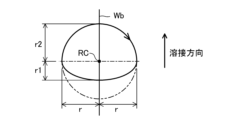
- An eighth aspect is the arc welding method according to any one of the first to seventh aspects, wherein the weaving operation is a spiral weaving operation that moves along a spiral trajectory, and on the boundary position, the The distance from the center position of the spiral locus to the spiral locus on the rear side in the welding direction is shorter than the distance to the spiral locus on the front side in the welding direction.
- the distance from the spiral center position to the spiral locus on the rear side in the welding direction on the boundary position is shorter than the distance to the spiral locus on the front side in the welding direction, thereby improving penetration. It is possible to secure the build-up of the bead by suppressing it.
- a ninth aspect is the arc welding method according to any one of the first to eighth aspects, in which the welding wire is fed at a constant speed in at least one of the first welding and the second welding.
- the welding wire is fed at a constant speed.
- a tenth aspect is the arc welding method according to any one of the first to eighth aspects, wherein at least one of the first welding and the second welding alternately and periodically forwards and reverses the welding wire. to repeatedly feed the welding wire.
- the welding wire is fed by alternately and periodically repeating forward feeding and reverse feeding.
- the heat input given to the object to be welded can be reduced. Specifically, when the welding wire short-circuits with the object to be welded, the welding voltage becomes close to 0 V, and the heat input, which is the amount of heat per unit time, becomes extremely small.
- the welding wire when the welding wire is fed back and forth, the welding wire is fed forward, and when the welding wire short-circuits with the object to be welded, the welding wire is fed backward, and when an arc is generated between the welding wire and the object to be welded, welding is performed. Since the wire is accelerated forward, the number of short-circuits can be greatly improved compared to the case where the welding wire is constantly fed toward the object to be welded. As a result, the effect of periodically cooling the object to be welded can be obtained.
- An eleventh aspect is the arc welding method according to any one of the second to tenth aspects, wherein the weaving operation is a spiral weaving operation that moves along a spiral trajectory, and the short-circuit welding that performs the short-circuit welding
- the third welding is performed in which the period and the pulse welding period for performing the pulse welding are switched multiple times, and the proportion of the pulse welding period is increased in front of the center position of the spiral locus in the welding direction, while welding The proportion of the short-circuit welding period is increased in the backward direction.
- pulse welding has a higher heat input than short-circuit welding, and a molten pool is formed by increasing the proportion of the pulse welding period in which high heat input pulse welding is performed forward in the welding direction.
- the molten pool is cooled by increasing the proportion of the short-circuit welding period in which short-circuit welding with a low heat input is performed behind the pulse welding in the welding direction.
- a twelfth aspect is an arc welding apparatus that feeds a welding wire, which is a consumable electrode, toward a welding object and generates an arc between the welding wire and the welding object for welding,
- the object to be welded has a first member and a second member having a larger heat capacity than the first member, and alternately crosses the boundary position between the first member and the second member a plurality of times,
- a welding unit that performs welding while a welding torch performs a weaving operation; while performing a second welding on the second member, wherein the first welding is at least a short-circuit welding and the second welding is at least a pulse welding is performed, and in at least one of the first welding and the second welding, a reverse polarity period in which the welding wire becomes the positive electrode and the welding object becomes the negative electrode, and the welding wire becomes the negative electrode and the welding object becomes the positive electrode.
- a welding current is passed through the welding wire and the object to be welded so that the positive polarity period is alternately repeated a plurality of
- short-circuit welding has a lower heat input than pulse welding, and by performing low-heat-input short-circuit welding on the first member having a small heat capacity, burn-through of the first member is prevented. can be suppressed. In addition, by performing high heat input pulse welding on the second member having a large heat capacity, insufficient penetration can be suppressed.
- FIG. 1 is a schematic configuration diagram of an arc welding apparatus according to this embodiment.
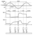
- FIG. 2 is a diagram showing waveforms of welding current, welding voltage, and welding wire feed speed in short-circuit welding, and droplet transfer states.
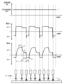
- FIG. 3 is a diagram showing waveforms of welding current, welding voltage, and welding wire feed speed in pulse welding, and droplet transfer states.
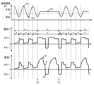
- FIG. 4 is a diagram showing waveforms of welding current, welding voltage, and welding wire feed speed in pulse mix welding.
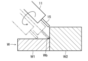
- FIG. 5 is a side cross-sectional view showing a state in which arc welding is performed while performing a spiral weaving operation.
- FIG. 6 is a perspective view showing a state of arc welding while performing a spiral weaving operation.
- FIG. 7 is a perspective view for explaining the timing of switching between short-circuit welding, pulse welding, and pulse mix welding.
- FIG. 8 is a diagram showing the trajectory of the spiral weaving motion according to the modified example of the present embodiment.
- the arc welding apparatus 1 welds the object W to be welded by generating an arc 16 between the welding wire 15, which is a consumable electrode, and the object W to be welded.
- the arc welding device 1 has a welding unit 10 and a control section 30.
- the welding unit 10 has a welding torch 11 , a feed motor 12 , a robot 13 and a power converter 20 .
- the feed motor 12 feeds the welding wire 15 to the welding torch 11 at a predetermined feed speed.
- the robot 13 has multiple joints.
- a welding torch 11 is attached to the tip of the robot 13 .
- the robot 13 moves the position of the welding torch 11 with respect to the object W to be welded. Although details will be described later, the robot 13 causes the welding torch 11 to spiral weave along a spiral trajectory.
- the power conversion section 20 has a primary side rectification section 21 , a switching section 22 , a main transformer 23 , a secondary side rectification section 24 , a reactor 25 , a voltage detection section 26 and a current detection section 27 .
- the primary side rectifying section 21 rectifies and outputs the output of the input power supply 5 .
- the switching section 22 converts the DC output from the primary side rectifying section 21 into AC.
- a switching unit 22 controls a welding output consisting of a welding current and a welding voltage.
- the main transformer 23 converts the AC voltage output by the switching section 22 .
- the output of the main transformer 23 is output as welding output via the secondary side rectifier 24 and the reactor 25 .
- the secondary rectifier 24 rectifies the secondary output of the main transformer 23 .
- Voltage detector 26 detects welding voltage V.
- Current detector 27 detects welding current I. As shown in FIG.
- the control unit 30 includes a drive unit 31, a short-circuit welding control unit 33 that performs control for first welding including short-circuit welding, a pulse welding control unit 32 that performs control for second welding including pulse welding, A pulse mix welding control unit 34 that performs control for the third welding described later, a welding condition setting unit 35, a storage unit 36, a feed speed control unit 37, a first switching unit 38, and a second switching unit. 39 and a robot control unit 40 .
- the driving section 31 controls the switching section 22 .
- the pulse welding control section 32 performs control for pulse welding.
- the short-circuit welding control section 33 performs control for short-circuit welding.
- the pulse mix welding control section 34 performs control for the third welding.
- the third welding is a welding method in which short-circuit welding and pulse welding are alternately repeated multiple times each at a fixed number of times.
- the third welding is defined as "pulse mix welding", and this expression is used in the following description.
- the feeding of the welding wire 15 is basically forward and reverse feeding of the welding wire 15 in the case of short-circuit welding, and the feeding of the welding wire 15 in the case of pulse welding is fundamentally constant. preferably. However, it is not necessarily limited to this form.
- the feeding speed of the welding wire 15 may be changed during pulse welding.
- the welding wire 15 may be fed at a constant rate during short-circuit welding.
- the number of pulses during pulse welding and the number of short circuits during short circuit welding may be gradually changed.
- the number of pulses during pulse welding and the number of short circuits during short-circuit welding may be gradually changed.
- sudden changes in heat input can be suppressed.
- FIG. 4 which will be described later, the number of pulses is two and the number of short circuits is repeated three times, but the number of pulses may be changed to three and the number of short circuits may be changed to two and repeated multiple times. Note that the number of pulses and the number of short circuits are merely examples, and are not limited to these.
- the timing of gradually changing the number of pulses and the number of short circuits may be, for example, a predetermined welding distance, a predetermined welding time, or each preset teaching point.
- the welding condition setting unit 35 sets welding conditions including welding current and welding voltage. Specifically, the welding condition setting unit 35 controls the set welding current for welding, the set welding voltage for welding, the feeding speed of the welding wire 15, the type of shielding gas, the material of the welding wire 15, the welding wire 15 diameter, pulse welding period and pulse output frequency, short circuit welding period and short circuit output frequency, etc. are set.
- the shield gas is used differently depending on the welding wire material and application.
- argon gas (Ar) is used for welding aluminum alloys.
- MIG gas (98% Ar+2% O2) is used for welding stainless steel.
- MAG gas 80% Ar+20% CO2) is used for mild steel welding.
- Carbon dioxide gas (CO2) is used when welding of mild steel is cost-sensitive.
- the kind of shielding gas is just an example.
- a predetermined threshold value is stored in the storage unit 36 .
- the thresholds stored in the storage unit 36 are thresholds for welding parameters related to the heat input applied to the welding target W, such as welding current, welding voltage, and feed speed. Based on the output from the welding condition setting unit 35, the storage unit 36 outputs pre-stored welding operations, appropriate control values, the feeding speed of the welding wire 15, and the like.
- the feed speed control unit 37 controls the feed speed of the welding wire 15 according to the welding current set by the welding condition setting unit 35 .
- the feeding speed and the welding current are mutually correlated. More specifically, the average welding speed as a moving average (also referred to as feed rate) and the average welding current as an average current as a moving average (also referred to as set current) are correlated with each other.
- the first switching unit 38 outputs a signal for welding output of any one of the pulse welding control unit 32, the short-circuit welding control unit 33, and the pulse mix welding control unit 34 according to the output of the storage unit 36.
- the second switching unit 39 selects one of the feed speed outputs of the pulse welding control unit 32, the short-circuit welding control unit 33, and the pulse mix welding control unit 34 according to the output of the storage unit 36.
- the robot control unit 40 controls the operation of the robot 13.
- the robot control unit 40 moves the welding torch 11 along the welding direction of the object W to be welded by giving a current command to a motor (not shown) of each axis of the robot 13 .
- the arc welding apparatus 1 supplies a shielding gas from a gas supply port (not shown) to shield the welding location of the welding object W from the outside air while supplying current between the welding wire 15 and the welding object W.
- an arc 16 is generated between the welding wire 15 and the object W to be welded, and the heat of the arc 16 melts the tip of the welding wire 15 and part of the object W to be welded.
- the melted welding wire 15 becomes a droplet and drips onto the object W to be welded, forming a molten pool together with a part of the object W melted by the heat of the arc 16 .
- the welding torch 11 moves in the welding direction while spirally weaving the object W to be welded.
- a bead is formed on the object W to be welded as the welding torch 11 moves, and the object W to be welded is welded.
- the arc welding device 1 welds the welding target W while switching between short-circuit welding, pulse welding, and pulse-mix welding.
- Fig. 2 is a diagram showing waveforms of welding current, welding voltage, and welding wire feed speed in short-circuit welding, and a state of droplet transfer.
- the vertical axis indicates the welding current I, the welding voltage V, and the feed speed WF, and the horizontal axis indicates time.
- short-circuit welding there is a short-circuit period in which the welding wire 15 and the object W to be welded are in contact with each other and short-circuited, and an arc state in which an arc 16 is generated between the welding wire 15 and the object W to be welded.
- the welding current I is controlled so as to alternately transition to an arc period of .
- the welding wire 15 and the object W to be welded are short-circuited.
- An arc 16 is generated between the welding wire 15 and the object W to be welded during the arc period.
- a welding current of 100 A is applied to the welding wire 15, for example.
- P1 indicates the time point at which the short circuit is started, and in the short circuit period from P1 to P2, the short circuit current is gradually increased after outputting the short circuit initial current for a predetermined time from the time point P1.
- P2 indicates the point in time when the short circuit state ends and the arc state occurs.
- the first welding current of peak current is output immediately after the arc is generated, and then the welding current is shifted to the second welding current lower than the first welding current.
- From P2 to P3 is an arc period in which an arc 16 is generated between the welding wire 15 and the object W to be welded. During this arc period, an arc 16 is generated between the welding wire 15 and the object W to be welded, and the heat of the arc 16 forms a droplet at the tip of the welding wire 15 and partially melts the object W to be welded.
- P3 indicates the point in time when a short circuit occurs next to P1, and is in the same state as at point P1.
- the short-circuit welding alternately and periodically repeats the short-circuit period from P1 (P3) to P2 and the short-circuit period from P2 to P3.
- the welding wire is fed with a predetermined frequency and a predetermined velocity amplitude in a sinusoidal waveform having this as a basic waveform, and the forward feed and the reverse feed are alternately repeated multiple times. control.
- a short circuit occurs around time P1
- an arc occurs around time P2.
- the next short circuit occurs around the time point P3.
- FIG. 3 is a diagram showing the waveforms of the welding current, welding voltage, and welding wire feed speed in pulse welding, and the state of droplet transfer.
- the vertical axis indicates the welding current I, the welding voltage V, and the feed speed WF, and the horizontal axis indicates time.
- the welding current is set to 200A, for example.
- the arc welding device 1 sets the wire feeding speed based on the set welding current I. Various pulse parameters forming the AC pulse waveform are set based on this wire feed speed.
- the pulse parameters are, as shown in FIG. the sexual current value Ien and the like.
- the feeding speed of the welding wire 15 is maintained at a constant feeding speed WF1.
- the welding current I is controlled so that the welding wire 15 becomes negative and the welding target W becomes positive during the positive polarity period Ten of EN(-) of the positive polarity region.
- the welding current I is controlled so that the welding wire 15 becomes the positive electrode and the welding target W becomes the negative electrode.
- the welding current I gradually increases in absolute value toward the peak current value Ip during the reverse polarity period Tep of EP(+) in the reverse polarity region, and is maintained at the peak current value Ip during the peak current period Tp.
- the absolute value of the welding current I gradually decreases from the peak current value Ip toward the base current value Ib, and is maintained at the base current value Ib during the base current period Tb.
- the reverse polarity period Tep of the reverse polarity region EP(+) is switched to the positive polarity period Ten of the positive polarity region EN( ⁇ ), and the welding current I changes from the base current value Ib to the positive polarity current value Ien. .
- the arc welding apparatus 1 generates an arc 16 between the welding wire 15 and the object W to be welded, and the heat of the arc 16 forms a droplet at the tip of the welding wire 15 and partially melts the object W to be welded. melt.
- the droplets formed at the tip of the welding wire 15 move from the tip of the welding wire 15 to the object W to be welded by droplet transfer, forming a molten pool on the object W to be welded. In this way, the transfer of the droplets does not short-circuit the welding wire 15 and the object W to be welded, the arc 16 is continuously generated at the peak current and the base current, and the droplets formed at the tip of the welding wire 15 are , so that one pulse and one drop in which one droplet transfers to the welding object W for each pulse of one peak current is released in the air from the tip of the welding wire 15, and the welding object Go to W.
- the arc welding apparatus 1 maintains the arc length H of the arc 16 at the reference arc length H1 in the droplet separation state after droplet transfer.
- Fig. 4 is a diagram showing waveforms of welding current, welding voltage, and welding wire feed speed in pulse mix welding.
- Pulse mix welding is welding in which a pulse welding period Tp in which pulse welding is performed and a short-circuit welding period Ts in which short-circuit welding is performed are alternately repeated multiple times.
- pulse mix welding which is a combination of direct current short-circuit welding as direct current welding and alternating current pulse welding as alternating current welding, will be described.
- the vertical axis indicates the welding current I, the welding voltage V, and the feed speed WF, and the horizontal axis indicates time.
- AC pulse welding is performed during the pulse welding period Tp.
- the welding wire 15 is the positive electrode and the welding object W is the negative electrode in the reverse polarity region EP (+), and the welding wire 15 is the negative electrode in the positive polarity region EN (-).
- the welding current I is controlled so as to alternately repeat a positive polarity period in which the workpiece W becomes the positive electrode.
- Direct current short-circuit welding is performed during the short-circuit welding period Ts.
- the welding wire 15 is the positive electrode and the welding object W is the negative electrode in the EP (+) of the reverse polarity region, and the welding wire 15 and the welding object W are short-circuited.
- the welding current I is controlled to transition alternately between a short-circuit period S of the wire 15 and one or more arc periods A that generate an arc 16 between the welding wire 15 and the work piece W to be welded.
- the pulse welding period Tp and the short-circuit welding period Ts are alternately repeated such that the pulse welding period Tp follows the short-circuit welding period Ts, and the short-circuit welding period Ts follows the pulse welding period Tp.
- the feed speed control unit 37 gives a control output to the feed motor 12 so that the feed speed WF of the welding wire 15 becomes a preset feed speed during the pulse welding period Tp and the short-circuit welding period Ts. As a result, the welding wire 15 is fed at the constant third feeding speed WF3 during the pulse welding period Tp.
- the feeding speed WF of the welding wire 15 is changed according to a periodic waveform having a predetermined amplitude and period.
- the feed speed WF shown in FIG. 4 varies according to a sine wave as a periodic waveform.
- the short circuit is opened at the pulse start time Tps at which the number of short circuits preset by the welding condition setting unit 35 has been counted.
- control is performed so that the reverse polarity peak of the AC pulse is output as it is.
- the pulse start time Tps may be the time when the time preset by the welding condition setting unit 35 has elapsed.
- a pulse welding period Tp for performing pulse welding is started from the pulse start time Tps.
- the pulse mix welding control unit 34 starts the pulse welding period Tp and generates the first pulse among the plurality of pulses.
- the feed speed WF continues to change according to the periodic waveform during the short-circuit welding period Ts, and the welding wire 15 is fed at the pulse welding period Tp set in advance by the welding condition setting unit 35.
- the feeder 14 feeds the welding wire 15 at the third feed speed WF3. .
- the pulse mix welding control unit 34 After that, during the pulse welding period Tp, when the number of pulses set in advance by the welding condition setting unit 35 is counted, or when the time set in advance by the welding condition setting unit 35 elapses, the pulse mix welding control unit 34 After forming the last pulse, the welding current I is changed from the positive polarity peak of the AC pulse directly to the peak current of the short-circuit welding.
- the feed speed WF is changed from the third feed speed WF3 during the pulse welding period Tp according to the above-described periodic waveform, and the welding wire 15 is fed forward and backward. started sending to
- the pulse welding period Tp and the short-circuit welding period Ts are alternately repeated under the set conditions, and the welding wire 15 is fed at the optimum feeding speed WF in each mode at that time. I do.
- the welding wire is arranged so that the reverse polarity period and the positive polarity period are alternately repeated multiple times.
- the heat input given to the welding object W is can be reduced, and the welding amount of the welding wire 15 can be increased.
- the object W to be welded melts during the reverse polarity period, while the welding wire 15 melts during the positive polarity period.
- the reversed polarity in which the welding wire 15 is positive and the welding object W is negative is continuous.
- the polarities of the welding current I supplied to the welding wire 15 and the welding object W are switched so that the period is alternately repeated a plurality of times, and the welding wire 15 becomes the negative electrode and the welding object W becomes the positive electrode periodically.
- AC pulse welding has a larger heat input than DC short-circuit welding and a smaller heat input than DC pulse welding.
- short-circuit welding, pulse welding, and pulse-mix welding are switched according to the heat capacity of the object W to be welded.
- the object W to be welded has a first member W1 and a second member W2.
- the plate thickness of the second member W2 is thicker than the plate thickness of the first member W1. Therefore, the heat capacity of the second member W2 is larger than the heat capacity of the first member W1.
- the first member W1 and the second member W2 are made of aluminum, for example.
- the first member W1 and the second member W2 are arranged in a state of facing each other.
- the position where the first member W1 and the second member W2 meet is the boundary position Wb between the first member W1 and the second member W2.
- the arc welding apparatus 1 performs welding while spirally weaving the welding torch 11 so as to alternately cross the boundary position Wb between the first member W1 and the second member W2 a plurality of times.
- the spiral weaving operation is an operation in which the welding torch 11 is moved along a spiral locus by moving the welding torch 11 along a circular locus in the welding direction.
- the welding wire 15 fed from the welding torch 11 is separated by the rotation radius r from the rotation center RC moving in the welding direction on the boundary position Wb between the first member W1 and the second member W2. In addition, it turns so as to revolve around the center of rotation RC at a predetermined rotation frequency.
- the size of the radius of gyration r shown in FIG. 6 is merely an example, and the present invention is not limited to this.
- the welding torch 11 may be moved to a position where the welding wire 15 can be supplied to the upper surface of the second member W2.
- the arc welding apparatus 1 switches the welding operation so that the first welding is performed on the first member W1 and the second welding is performed on the second member W2 during the spiral weaving operation.
- the first welding includes at least low heat input short-circuit welding.
- the second welding includes at least high heat input pulse welding.
- a third weld is performed in at least one of the first weld and the second weld.
- the third welding is pulse-mix welding in which short-circuit welding and pulse welding are alternately repeated multiple times each at a predetermined number of times.
- the arc welding start position on the boundary position Wb between the first member W1 and the second member W2 is 0°, and the arc is rotated clockwise around the rotation center RC in the welding direction. Welding shall be performed.
- the section from 20° to 160° is the first section 41
- the section from 160° to 190° is the second section 42
- the section from 190° to 350° is the third section 43
- the section from 350° to 20°. is the fourth segment 44 .
- the angle range of each section is just an example.
- the first switching unit 38 selects the output of the short-circuit welding control unit 33 suitable for the first member W1 having a small heat capacity in the first welding for welding the first member W1, and performs short-circuit welding. conduct.
- the first switching section 38 may select the output of the pulse mix welding control section 34 to perform pulse mix welding after the start of short-circuit welding.
- Pulse mix welding is a third welding in which a pulse welding period Tp in which pulse welding is performed and a short-circuit welding period Ts in which short-circuit welding is performed are alternately repeated multiple times. It is a weld with intermediate properties with low heat input. By performing pulse mix welding, it is possible to suppress sudden changes in heat input when the welding current is changed.
- the controller 30 controls the welding unit so that the proportion of the short-circuit welding period Ts in which short-circuit welding is performed during pulse mix welding is greater than the pulse welding period Tp in which pulse welding is performed. 10 operations. This allows pulse-mix welding to be performed under appropriate conditions. In the first welding, only short-circuit welding may be performed, and pulse mix welding may not be performed. Further, in pulse mix welding, the number of pulses during pulse welding and the number of short circuits during short circuit welding may be gradually changed.
- the second section 42 is a region spanning the first member W1 and the second member W2.
- the welding operation is performed such that the first welding in which at least short-circuit welding is performed on the first member W1 is performed, and the second welding in which at least pulse welding is performed on the second member W2 is performed. switch.
- the first switching unit 38 selects the output of the pulse mix welding control unit 34 and alternately repeats the pulse welding period Tp in which pulse welding is performed and the short-circuit welding period Ts in which short-circuit welding is performed multiple times. Pulse mix welding is performed as the third welding. By performing pulse mix welding, it is possible to suppress sudden changes in heat input when the welding current is changed.
- the control unit 30 determines that the proportion of the short-circuit welding period Ts in which short-circuit welding is performed during pulse mix welding is greater than the pulse welding period Tp in which pulse welding is performed. The operation of the welding unit 10 is controlled so that the Further, when pulse mix welding is performed in the second welding performed on the second member W2, the control unit 30 sets the ratio of the short circuit welding period Ts in which short circuit welding is performed during pulse mix welding to the pulse welding period in which pulse welding is performed. The operation of the welding unit 10 is controlled so as to be less than Tp.
- the proportion of the short-circuit welding period Ts in which short-circuit welding is performed during pulse mix welding is greater than when performed on the second member W2, and the second member When performing short-circuit welding on W2, the ratio of the short-circuit welding period Ts during which short-circuit welding is performed during pulse mix welding shall be smaller than when performing short-circuit welding on the first member W1.
- the proportion of the short-circuit welding period in which short-circuit welding with a small heat input is performed is increased, and welding is performed.
- the target region is the second member W2 having a larger heat capacity than the first member W1
- the proportion of the pulse welding period in which the heat input is larger than that of the short-circuit welding can be increased. can perform pulse-mix welding.
- pulse mix welding the number of pulses during pulse welding and the number of short circuits during short circuit welding may be gradually changed.
- the control unit 30 increases the welding current applied to the welding wire 15 before the welding torch 11 moving from the first member W1 to the second member W2 crosses the boundary position Wb. control 10.
- the welding current applied when welding torch 11 crosses boundary position Wb so that welding torch 11 moves from first member W1 to second member W2 is the welding current applied before welding torch 11 crosses boundary position Wb. greater than the current.
- the average welding current (set current ) is greater than the average welding current applied before the welding torch 11 crosses the boundary position Wb.
- a larger welding current is applied to the welding wire 15 in the second section 42 than the welding current applied to the welding wire 15 in the first section 41 .
- the average welding current and the feeding amount of the welding wire 15 are in a corresponding relationship.
- the amount of welding wire 15 fed may be increased compared to the first section 41 and the third section 43 to secure the amount of welding and welding may be performed.
- the first switching unit 38 selects the output of the pulse welding control unit 32 suitable for the second member W2 having a large heat capacity in the second welding for welding the second member W2, and performs pulse welding. conduct.
- the first switching unit 38 selects the output of the pulse mix welding control unit 34 to switch between the pulse welding period Tp during which pulse welding is performed and the short-circuit welding period Ts during which short-circuit welding is performed.
- Pulse mix welding may be performed as the third welding in which the steps are alternately repeated a plurality of times. By performing pulse mix welding, it is possible to suppress sudden changes in heat input when the welding current is changed.
- the control unit 30 sets the proportion of the pulse welding period Tp in which pulse welding is performed during pulse mix welding to be higher than the short-circuit welding period Ts in which short-circuit welding is performed.
- the operation of the welding unit 10 is controlled so that the This allows pulse-mix welding to be performed under appropriate conditions.
- in the second welding only pulse welding may be performed, and pulse mix welding may not be performed.
- the ratio of the pulse welding period Tp in which pulse welding is performed or the number of pulses during pulse welding, the ratio of the short-circuit welding period Ts in which short-circuit welding is performed, or the number of short circuits during short-circuit welding are gradually changed.
- the fourth section 44 is a region spanning the first member W1 and the second member W2.
- the welding operation is performed such that the first welding in which at least short-circuit welding is performed on the first member W1 is performed, and the second welding in which at least pulse welding is performed on the second member W2 is performed. switch.
- the first switching unit 38 selects the output of the pulse mix welding control unit 34 and alternately repeats the pulse welding period Tp in which pulse welding is performed and the short-circuit welding period Ts in which short-circuit welding is performed multiple times. Pulse mix welding is performed as the third welding. By performing pulse mix welding, it is possible to suppress sudden changes in heat input when the welding current is changed.
- the control unit 30 determines that the proportion of the short-circuit welding period Ts in which short-circuit welding is performed during pulse mix welding is greater than the pulse welding period Tp in which pulse welding is performed. The operation of the welding unit 10 is controlled so that the Further, when pulse mix welding is performed in the second welding performed on the second member W2, the control unit 30 sets the ratio of the short circuit welding period Ts in which short circuit welding is performed during pulse mix welding to the pulse welding period in which pulse welding is performed. The operation of the welding unit 10 is controlled so as to be less than Tp.
- the proportion of the short-circuit welding period Ts in which short-circuit welding is performed during pulse mix welding is greater than when performed on the second member W2, and the second member When performing short-circuit welding on W2, the ratio of the short-circuit welding period Ts during which short-circuit welding is performed during pulse mix welding shall be smaller than when performing short-circuit welding on the first member W1.
- the proportion of the short-circuit welding period in which short-circuit welding with a small heat input is performed is increased, and welding is performed.
- the proportion of the pulse welding period in which the heat input is larger than that of the short-circuit welding can be increased. can perform pulse-mix welding.
- pulse mix welding the number of pulses during pulse welding and the number of short circuits during short circuit welding may be gradually changed.
- the fourth section 44 before the welding torch 11 crosses the boundary position Wb between the first member W1 and the second member W2 from the second member W2 having a large heat capacity toward the first member W1 having a small heat capacity. , during pulse mix welding, gradually increase the ratio of the short-circuit welding period Ts during which short-circuit welding is performed with a lower heat input than pulse welding. In other words, the ratio of the number of short-circuits in pulse mix welding when crossing the boundary position Wb is greater than the ratio of the number of short-circuits in pulse mix welding before the welding torch 11 crosses the boundary position Wb. .
- the ratio of the number of short circuits when the welding torch 11 crosses the boundary position Wb is made larger than the ratio of the number of short circuits before the welding torch 11 crosses the boundary position Wb, and the boundary position is detected before crossing the boundary position Wb.
- short-circuit welding has a lower heat input than pulse welding.
- pulse mix welding in which a short-circuit welding period Ts for performing short-circuit welding and a pulse welding period Tp for performing pulse welding are alternately repeated multiple times at a predetermined rate, in the short-circuit welding period Ts, short-circuit welding with a low heat input has a cooling effect. . Therefore, heat input to the first member W1 is suppressed, and burn-through can be suppressed. Further, during the pulse welding period Tp, the arc 16 spreads and the width of the bead widens, and the droplets of the welding wire 15 are regularly detached and transferred to the bead formed by high heat input pulse welding, and the spatter is generated. less.
- the welding speed can be increased without reducing the welding quality due to burn-through.
- the molten pool melted by high heat input pulse welding is cooled by low heat input short circuit welding during spiral weaving, and the scales of the bead are cooled. considered to be easier to generate. As a result, the welding speed can be increased while ensuring the welding quality.
- the arc welding method using the arc welding apparatus 1 it is possible to improve the joint quality between members having different heat capacities. Specifically, at least short-circuit welding is performed on the first member W1 having a small heat capacity, and short-circuit welding with a low heat input is mainly performed compared to pulse welding, in other words, short-circuit welding that performs low heat input short-circuit welding. By increasing the ratio of the period Ts, burn-through of the first member W1 can be suppressed. Further, at least pulse welding is performed on the second member W2 having a large heat capacity, and high heat input pulse welding is mainly performed, in other words, the proportion of the pulse welding period Tp in which high heat input pulse welding is performed is increased. By doing so, it is possible to suppress the occurrence of insufficient penetration.
- the heat capacities are different by adjusting the welding conditions.
- Welding parameters welding current I, welding voltage V, feeding speed of the welding wire 15, thickness of the welding object W, etc.
- short-circuit welding, pulse welding, and pulse mix welding can be set.
- the arc welding apparatus 1 performs welding while spirally weaving the welding torch 11 along the welding direction.
- the welding wire 15 fed from the welding torch 11 is separated from the rotation center RC moving on the boundary position Wb between the first member W1 and the second member W2 by a rotation radius r and a predetermined Rotational movement is performed so as to revolve around the center of rotation RC at the rotation frequency.
- the distance r1 from the rotational position RC of the spiral locus to the spiral locus on the rear side in the welding direction is set to the forward side in the welding direction. is shorter than the distance r2 to the spiral trajectory.
- the distance r2 to the spiral locus on the front side in the welding direction is set to the same length as the rotation radius r, and the distance r1 to the spiral locus on the rear side in the welding direction is set shorter than the distance r2.
- the distance r1 may be the same length as the turning radius r, and the distance r2 may be longer than the distance r1.
- the thickness of the second member W2 is made thicker than the thickness of the first member W1 so as to have different heat capacities.
- the heat capacities may be different.
- the first member W1 and the second member W2 may have the same plate thickness, and the first member W1 may be made of aluminum and the second member W2 may be made of a mild steel material.
- the first member W1 has a small heat capacity
- the second member W2 has a large heat capacity
- the heat capacities are different.
- the second member W2 has a relatively large heat capacity compared to the first member W1.
- arc welding is performed while the first member W1 and the second member W2 are butted against each other, but the present invention is not limited to this form.
- the first member W1 and the second member W2 may be overlapped in the thickness direction, and the corners of the first member W1 and the second member W2 may be arc-welded.
- the heat capacity of the overlapped portion of the first member W1 and the second member W2 is larger than the heat capacity of the portion where the first member W1 and the second member W2 are not overlapped. Become. Therefore, the overlapped portion of the two plate materials is assumed to be the second member, and the non-overlapping portion is assumed to be the first member. do it.
- pulse mix welding is performed in the first welding and the second welding, but it is not limited to this form.
- the first welding may be short-circuit welding and the second welding may be pulse welding.
- the first welding may be short-circuit welding, and the second welding may be pulse-mix welding.
- the first welding may be pulse mix welding, and the second welding may be pulse welding.
- the welding torch 11 is made to spirally weave, but it is not limited to this form.
- the welding torch 11 is periodically oscillated left and right with respect to the boundary position Wb so as to alternately cross the boundary position Wb of the first member W1 and the second member W2 a plurality of times, and the weaving progresses in the welding progress direction.
- the welding torch 11 may be weaved in a zigzag manner. In this case, it is preferable that the weaving operation is performed to oscillate periodically to the left and right with respect to the boundary position Wb at a fine and acute angle.
- the radius r of the spiral trajectory during the spiral weaving operation is set to the same radius r on the first member W1 side and the second member W2 side, but may be set to different radii.
- the welding wire 15 is fed by periodically repeating forward feeding and reverse feeding of the welding wire 15, but it is not limited to this form.
- the welding wire 15 may be fed at a constant speed.
- the proportion of pulse welding may be increased in the forward direction in the welding direction from the center position of the spiral trajectory, while the proportion of short-circuit welding may be increased in the rearward direction in the welding direction. .
- a molten pool is formed by increasing the ratio of high heat input pulse welding in the front of the welding direction, and the molten pool is formed by increasing the ratio of low heat input short-circuit welding in the rear of the welding direction. is cooled.
- an arc welding method that combines direct current short-circuit welding and alternating current pulse welding has been described, but it is not limited to this form.
- an arc welding method that combines AC short-circuit welding and AC pulse welding may be used.
- an arc welding method combining AC short-circuit welding and DC pulse welding may be used.
- the amount of heat input to the welding object W is the lowest in AC short-circuit welding (forward and reverse wire feeding method), Short-circuit welding (forward and reverse wire feeding method), DC short-circuit welding (constant wire feeding method), AC pulse welding, and DC pulse welding are used in this order.
- AC short-circuit welding as AC welding has a lower heat input than DC short-circuit welding as DC welding.
- short-circuit welding and pulse welding are simply referred to, they indicate direct-current short-circuit welding and direct-current pulse welding as direct current welding.
- DC welding the reversed polarity (reverse polarity period) in which the welding wire 15 becomes the positive electrode and the object to be welded W becomes the negative electrode continues.
- the positive polarity (positive polarity period) in which W is positive may be continuous. Since the positive polarity continues, the amount of heat input to the object W to be welded decreases, while the welding wire 15 melts more, resulting in a greater amount of welding.
- the present invention is extremely useful and has high industrial applicability because it can improve the quality of bonding between members with different heat capacities.
- Reference Signs List 1 arc welding device 10 welding unit 11 welding torch 13 robot 15 welding wire 30 control unit 32 pulse welding control unit 33 short-circuit welding control unit 34 pulse mix welding control unit 40 robot control unit W object to be welded W1 first member W2 second member Wb Boundary position
Abstract
The thermal capacity of a second member W2 is higher than that of a first member W1. Welding is performed by causing a welding torch 11 to take a weaving motion so as to move across the boundary location Wb between the first member W1 and the second member W2. During the weaving motion, first welding is performed on the first member W1, and second welding is performed on the second member W2. In the first welding, at least short circuit welding is performed. In the second welding, at least pulse welding is performed.
Description
本発明は、アーク溶接方法及びアーク溶接装置に関するものである。
The present invention relates to an arc welding method and an arc welding apparatus.
特許文献1には、パルス溶接と短絡溶接とを交互に繰り返して行う消耗電極式のアーク溶接において、パルス溶接から短絡溶接へ移行直前の溶接電流を、パルスでのベース電流より下げるようにした構成が開示されている。
In Patent Document 1, in consumable electrode type arc welding in which pulse welding and short-circuit welding are alternately repeated, the welding current immediately before the transition from pulse welding to short-circuit welding is made lower than the base current in the pulse. is disclosed.
ところで、板厚や材質の違いに起因して熱容量が異なる2つの部材をアーク溶接する場合、例えば、板厚の薄い部材に対して高入熱のパルス溶接を行うと、部材が溶落ちてしまい、接合不良が発生するおそれがある。
By the way, when arc welding two members with different heat capacities due to differences in plate thickness or material, for example, if pulse welding is performed with a high heat input to a thin member, the member may burn through. , there is a risk that poor bonding may occur.
本発明は、かかる点に鑑みてなされたものであり、その目的は、熱容量の異なる部材同士の接合品質を向上させることにある。
The present invention has been made in view of this point, and its purpose is to improve the bonding quality between members having different heat capacities.
第1の態様は、消耗電極である溶接ワイヤを溶接対象物へ向けて送給し、該溶接ワイヤと該溶接対象物との間にアークを発生させて溶接するアーク溶接方法であって、前記溶接対象物は、第1部材と、該第1部材よりも熱容量の大きい第2部材と、を有し、前記第1部材と前記第2部材との境界位置を交互に複数回横切るように、溶接トーチをウィービング動作しながら溶接を行うステップと、前記ウィービング動作中に、前記第1部材に対して第1溶接を行う一方、前記第2部材に対して第2溶接を行うように、溶接動作を切り替えるステップと、を備え、前記第1溶接では、少なくとも短絡溶接が行われ、前記第2溶接では、少なくともパルス溶接が行われ、前記第1溶接及び前記第2溶接の少なくとも一方において、前記溶接ワイヤが正極となり前記溶接対象物が負極となる逆極性期間と、該溶接ワイヤが負極となり該溶接対象物が正極となる正極性期間とが交互に複数回繰り返されるように、溶接電流を該溶接ワイヤと該溶接対象物とに流す。
A first aspect is an arc welding method in which a welding wire, which is a consumable electrode, is fed toward a welding object, and an arc is generated between the welding wire and the welding object for welding, The object to be welded has a first member and a second member having a larger heat capacity than the first member, and alternately crosses the boundary position between the first member and the second member a plurality of times, welding while weaving a welding torch; and performing a first weld to the first member and a second weld to the second member during the weaving operation. wherein at least short-circuit welding is performed in the first welding, at least pulse welding is performed in the second welding, and in at least one of the first welding and the second welding, the welding The welding current is applied to the welding so that a reverse polarity period in which the wire becomes the positive electrode and the object to be welded becomes the negative electrode and a positive polarity period in which the welding wire becomes the negative electrode and the object to be welded becomes the positive electrode are alternately repeated multiple times. Flow through the wire and the object to be welded.
第1の態様では、第2部材は、第1部材よりも熱容量が大きい。第1部材と第2部材との境界位置を交互に複数回横切るように、溶接トーチをウィービング動作させながら溶接を行う。ウィービング動作中、第1部材に対して第1溶接を行う一方、第2部材に対して第2溶接を行う。第1溶接では、少なくとも短絡溶接が行われる。第2溶接では、少なくともパルス溶接が行われる。
In the first aspect, the second member has a larger heat capacity than the first member. Welding is performed while weaving the welding torch so as to alternately cross the boundary position between the first member and the second member a plurality of times. During the weaving operation, a first weld is made to the first member while a second weld is made to the second member. At least short-circuit welding is performed in the first welding. At least pulse welding is performed in the second welding.
これにより、熱容量の異なる部材同士の接合品質を向上させることができる。具体的に、熱容量の小さい第1部材に対して低入熱の短絡溶接を行うことで、第1部材が溶落ちてしまうのを抑えることができる。また、熱容量の大きい第2部材に対して高入熱のパルス溶接を行うことで、溶込み不足が生じるのを抑えることができる。
This makes it possible to improve the quality of bonding between members with different heat capacities. Specifically, by performing low heat input short-circuit welding on the first member having a small heat capacity, burn-through of the first member can be suppressed. In addition, by performing high heat input pulse welding on the second member having a large heat capacity, insufficient penetration can be suppressed.
このように、溶接トーチのウィービング動作と同期して、溶接法を切り替えることで、板厚の異なる溶接対象物や複雑な形状の溶接対象物の溶接において、適切な入熱を与えることができる。その結果、溶落ちが無く、所望の溶込み深さを得ることができる。
In this way, by switching the welding method in synchronization with the weaving operation of the welding torch, it is possible to apply an appropriate heat input when welding objects with different plate thicknesses or objects with complicated shapes. As a result, a desired penetration depth can be obtained without burn-through.
また、逆極性期間と正極性期間とが交互に複数回繰り返されるように、溶接ワイヤと溶接対象物とに流す溶接電流の極性を切り替えて、溶接電流を溶接ワイヤと溶接対象物とに流すようにした交流溶接では、溶接対象物に与える入熱を小さくしつつ、溶接ワイヤの溶着量を多くすることができる。
Also, the polarity of the welding current to be applied to the welding wire and the welding object is switched so that the reverse polarity period and the positive polarity period are alternately repeated multiple times, and the welding current is applied to the welding wire and the welding object. In AC welding, the amount of welding wire deposited can be increased while reducing the heat input to the object to be welded.
具体的に、交流溶接では、逆極性期間において溶接対象物が溶ける一方、正極性期間において溶接ワイヤが溶けることとなる。つまり、交流溶接では、直流溶接のように、溶接ワイヤが正極となり溶接対象物が負極となる逆極性(逆極性期間)が連続するのではなく、逆極性期間と正極性期間とが交互に複数回繰り返されるように、溶接ワイヤと溶接対象物とに流す溶接電流の極性を切り替えて、周期的に、溶接ワイヤが負極となり溶接対象物が正極となる正極性(正極性期間)に切り替わるため、溶接対象物に対する入熱量が少なくなる一方、溶接ワイヤが多く溶けることとなり、溶着量を多くすることができる。
Specifically, in AC welding, the object to be welded melts during the reverse polarity period, while the welding wire melts during the positive polarity period. In other words, in AC welding, unlike DC welding, the reversed polarity (reverse polarity period) in which the welding wire becomes the positive electrode and the object to be welded becomes the negative electrode is continuous. The polarity of the welding current to be applied to the welding wire and the object to be welded is switched repeatedly so that the welding wire is switched to the negative electrode and the object to be welded to the positive electrode (positive polarity period). While the amount of heat input to the object to be welded is reduced, a large amount of the welding wire is melted, and the amount of welding can be increased.
第2の態様は、第1の態様のアーク溶接方法において、前記第1溶接及び前記第2溶接の少なくとも一方では、前記短絡溶接を行う短絡溶接期間と前記パルス溶接を行うパルス溶接期間とを交互に複数回切り替える第3溶接が行われる。
A second aspect is the arc welding method of the first aspect, wherein in at least one of the first welding and the second welding, a short-circuit welding period in which the short-circuit welding is performed and a pulse welding period in which the pulse welding is performed alternately. A third weld is made by switching to .
第2の態様では、第1溶接及び第2溶接の少なくとも一方において、第3溶接を行う。第3溶接は、短絡溶接よりも入熱が高く且つパルス溶接よりも入熱が低い中間の特性を有する。第3溶接を行うことで、溶接電流を変化させた場合の急激な入熱の変化を抑えることができる。
In the second aspect, the third welding is performed in at least one of the first welding and the second welding. The third weld has intermediate properties of higher heat input than short-circuit welding and lower heat input than pulse welding. By performing the third welding, it is possible to suppress a rapid change in heat input when the welding current is changed.
第3の態様は、第2の態様のアーク溶接方法において、前記第1溶接で前記第3溶接を行う場合、該第3溶接中に行う前記短絡溶接の前記短絡溶接期間の割合を、前記パルス溶接の前記パルス溶接期間よりも多くするステップと、前記第2溶接で前記第3溶接を行う場合、該第3溶接中に行う前記パルス溶接の前記パルス溶接期間の割合を、前記短絡溶接の前記短絡溶接期間よりも多くするステップと、を備える。
A third aspect is the arc welding method of the second aspect, wherein when the third welding is performed in the first welding, the ratio of the short-circuit welding period of the short-circuit welding performed during the third welding is set to the pulse and when the third welding is performed in the second welding, the ratio of the pulse welding period of the pulse welding performed during the third welding is set to the above-mentioned pulse welding period of the short-circuit welding. greater than the short-circuit welding period.
第3の態様では、短絡溶接を行う短絡溶接期間とパルス溶接を行うパルス溶接期間とを含む。熱容量の小さい第1部材を第3溶接する場合、パルス溶接に比べて低入熱の短絡溶接を行う短絡溶接期間の割合を多くするようにしている。また、熱容量の大きい第2部材を第3溶接する場合、高入熱のパルス溶接を行うパルス溶接期間の割合を多くするようにしている。これにより、適切な条件下で、第3溶接を行うことができる。
The third aspect includes a short-circuit welding period in which short-circuit welding is performed and a pulse welding period in which pulse welding is performed. When performing the third welding of the first member having a small heat capacity, the proportion of the short-circuit welding period during which short-circuit welding with low heat input is performed is increased compared to pulse welding. Further, when the second member having a large heat capacity is subjected to the third welding, the proportion of the pulse welding period in which high heat input pulse welding is performed is increased. Thereby, the 3rd welding can be performed under suitable conditions.
第4の態様は、第2又は3の態様のアーク溶接方法において、前記第2溶接において、前記第2部材から前記第1部材へ向かうように、前記溶接トーチが前記境界位置を横切る前に、前記パルス溶接、前記第3溶接、及び前記短絡溶接の順に切り替えるステップを備える。
A fourth aspect is the arc welding method of the second or third aspect, wherein in the second welding, before the welding torch crosses the boundary position so as to move from the second member to the first member, A step of switching in order of the pulse welding, the third welding, and the short-circuit welding is provided.
第4の態様では、熱容量の大きい第2部材から熱容量の小さい第1部材に向かって溶接トーチを移動させる前に、徐々に短絡溶接に移行させるようにしている。これにより、パルス溶接、第3溶接、短絡溶接を連携させながら、急激な入熱の変化を抑えることができる。
In the fourth aspect, before the welding torch is moved from the second member with a large heat capacity toward the first member with a small heat capacity, the welding is gradually shifted to short-circuit welding. As a result, sudden changes in heat input can be suppressed while coordinating pulse welding, third welding, and short-circuit welding.
第5の態様は、第2~4の態様の何れか1つのアーク溶接方法において、前記第3溶接において、パルス溶接中のパルス回数及び短絡溶接中の短絡回数の少なくとも一方を徐々に変化させるステップを備える。
A fifth aspect is the arc welding method according to any one of the second to fourth aspects, wherein in the third welding, at least one of the number of pulses during pulse welding and the number of short circuits during short-circuit welding is gradually changed. Prepare.
第5の態様では、パルス溶接中のパルス回数及び短絡溶接中の短絡回数の少なくとも一方を徐々に変化させることで、急激な入熱の変化を抑えることができる。
In the fifth aspect, by gradually changing at least one of the number of pulses during pulse welding and the number of short circuits during short-circuit welding, it is possible to suppress sudden changes in heat input.
第6の態様は、第1~5の態様の何れか1つのアーク溶接方法において、前記溶接トーチが前記第1部材から前記第2部材へ向かうように、前記境界位置を横切る際に印加される溶接電流は、該溶接トーチが該境界位置を横切る前に印加される溶接電流よりも大きい。
A sixth aspect is the arc welding method according to any one of the first to fifth aspects, wherein the welding torch is applied when crossing the boundary position so as to move from the first member to the second member. A welding current is greater than the welding current applied before the welding torch crosses the boundary location.
第6の態様では、境界位置を横切る際に印加される溶接電流は、溶接電流の移動平均としての平均電流である平均溶接電流であり、境界位置を横切る際に、溶接ワイヤに印加する平均溶接電流を大きくすることで、境界位置における溶接ワイヤの送給量を増加させ、ビードの肉盛りを確保することができる。これにより、薄板と厚板との境界に生じる段差を埋めることができる。
In the sixth aspect, the welding current applied when crossing the boundary position is an average welding current that is an average current as a moving average of the welding current, and the average welding current applied to the welding wire when crossing the boundary position By increasing the current, it is possible to increase the feeding amount of the welding wire at the boundary position and ensure the build-up of the bead. As a result, a step formed at the boundary between the thin plate and the thick plate can be filled.
第7の態様は、第2~6の態様の何れか1つのアーク溶接方法において、前記溶接トーチが前記第2部材から前記第1部材へ向かうように、前記境界位置を横切る際の、前記第3溶接での前記短絡溶接の短絡回数の割合は、該溶接トーチが該境界位置を横切る前の、前記第3溶接での前記短絡溶接の短絡回数の割合よりも大きい。
A seventh aspect is the arc welding method according to any one of the second to sixth aspects, wherein when the welding torch crosses the boundary position from the second member toward the first member, the The percentage of short-circuit times of the short-circuit welds in weld 3 is greater than the percentage of short-circuit times of the short-circuit welds in weld 3 before the welding torch crosses the boundary location.
第7の態様では、境界位置を横切る際の短絡回数の割合を、溶接トーチが境界位置を横切る前の短絡回数の割合よりも大きくし、境界位置を横切る前から境界位置を横切る際に、短絡回数の割合を増加させることで、低入熱状態で、境界位置におけるビードの肉盛りを確保することができる。これにより、薄板と厚板との境界に生じる段差を埋めることができる。
In the seventh aspect, the ratio of the number of short circuits when the welding torch crosses the boundary position is made larger than the ratio of the number of short circuits before the welding torch crosses the boundary position, and when the welding torch crosses the boundary position from before crossing the boundary position, short circuits By increasing the ratio of the number of times, it is possible to ensure bead build-up at the boundary position in a low heat input state. As a result, a step formed at the boundary between the thin plate and the thick plate can be filled.
第8の態様は、第1~7の態様の何れか1つのアーク溶接方法において、前記ウィービング動作は、螺旋状の軌跡に沿って移動する螺旋ウィービング動作であり、前記境界位置上での、前記螺旋状の軌跡の中心位置から溶接方向の後方側の螺旋軌跡までの距離は、溶接方向の前方側の螺旋軌跡までの距離よりも短い。
An eighth aspect is the arc welding method according to any one of the first to seventh aspects, wherein the weaving operation is a spiral weaving operation that moves along a spiral trajectory, and on the boundary position, the The distance from the center position of the spiral locus to the spiral locus on the rear side in the welding direction is shorter than the distance to the spiral locus on the front side in the welding direction.
第8の態様では、境界位置上での、螺旋中心位置から溶接方向の後方側の螺旋軌跡までの距離を、溶接方向の前方側の螺旋軌跡までの距離よりも短くすることで、溶込みを抑えてビードの肉盛りを確保することができる。
In the eighth aspect, the distance from the spiral center position to the spiral locus on the rear side in the welding direction on the boundary position is shorter than the distance to the spiral locus on the front side in the welding direction, thereby improving penetration. It is possible to secure the build-up of the bead by suppressing it.
第9の態様は、第1~8の態様の何れか1つのアーク溶接方法において、前記第1溶接及び前記第2溶接の少なくとも一方では、前記溶接ワイヤを一定速度で送給する。
A ninth aspect is the arc welding method according to any one of the first to eighth aspects, in which the welding wire is fed at a constant speed in at least one of the first welding and the second welding.
第9の態様では、溶接ワイヤを一定速度で送給するようにしている。
In the ninth aspect, the welding wire is fed at a constant speed.
第10の態様は、第1~8の態様の何れか1つのアーク溶接方法において、前記第1溶接及び前記第2溶接の少なくとも一方では、前記溶接ワイヤの正送と逆送を交互に周期的に繰り返して該溶接ワイヤを送給する。
A tenth aspect is the arc welding method according to any one of the first to eighth aspects, wherein at least one of the first welding and the second welding alternately and periodically forwards and reverses the welding wire. to repeatedly feed the welding wire.
第10の態様では、溶接ワイヤの正送と逆送を交互に周期的に繰り返して溶接ワイヤを送給するようにしている。
In the tenth aspect, the welding wire is fed by alternately and periodically repeating forward feeding and reverse feeding.
これにより、溶接対象物に与える入熱を小さくすることができる。具体的に、溶接ワイヤが溶接対象物に短絡すると、溶接電圧が0V近くになり、単位時間当たりの熱量である入熱量が極端に小さくなる。
As a result, the heat input given to the object to be welded can be reduced. Specifically, when the welding wire short-circuits with the object to be welded, the welding voltage becomes close to 0 V, and the heat input, which is the amount of heat per unit time, becomes extremely small.
ここで、溶接ワイヤを正逆送する場合、溶接ワイヤを正送し、溶接ワイヤが溶接対象物に短絡すると溶接ワイヤを逆送し、溶接ワイヤと溶接対象物との間でアークが発生すると溶接ワイヤを正送へと加速するので、溶接ワイヤを溶接対象物に向かって一定送給する場合に比べて、短絡回数が飛躍的に向上する。これにより、溶接対象物を周期的に冷却する効果を得ることができる。
Here, when the welding wire is fed back and forth, the welding wire is fed forward, and when the welding wire short-circuits with the object to be welded, the welding wire is fed backward, and when an arc is generated between the welding wire and the object to be welded, welding is performed. Since the wire is accelerated forward, the number of short-circuits can be greatly improved compared to the case where the welding wire is constantly fed toward the object to be welded. As a result, the effect of periodically cooling the object to be welded can be obtained.
また、短絡時に溶接ワイヤを正逆送することで、スパッタの発生を抑え、溶接品質を高めることができる。
In addition, by feeding the welding wire forward and backward during a short circuit, it is possible to suppress the occurrence of spatter and improve welding quality.
第11の態様は、第2~10の態様の何れか1つのアーク溶接方法において、前記ウィービング動作は、螺旋状の軌跡に沿って移動する螺旋ウィービング動作であり、前記短絡溶接を行う前記短絡溶接期間と前記パルス溶接を行う前記パルス溶接期間とを複数回切り替える前記第3溶接を行い、前記螺旋状の軌跡の中心位置よりも溶接方向の前方において前記パルス溶接期間の割合を多くする一方、溶接方向の後方において前記短絡溶接期間の割合を多くする。
An eleventh aspect is the arc welding method according to any one of the second to tenth aspects, wherein the weaving operation is a spiral weaving operation that moves along a spiral trajectory, and the short-circuit welding that performs the short-circuit welding The third welding is performed in which the period and the pulse welding period for performing the pulse welding are switched multiple times, and the proportion of the pulse welding period is increased in front of the center position of the spiral locus in the welding direction, while welding The proportion of the short-circuit welding period is increased in the backward direction.
第11の態様では、パルス溶接は短絡溶接に比べて高入熱であり、溶接方向の前方において高入熱のパルス溶接を行うパルス溶接期間の割合を多くすることで溶融池が形成され、螺旋ウィービング動作において、溶接方向の後方においてパルス溶接に比べて低入熱の短絡溶接を行う短絡溶接期間の割合を多くすることで溶融池が冷却される。これにより、溶接対象物の溶落ちを抑えるとともに、ビードのウロコ状の波目を明瞭化することができる。
In the eleventh aspect, pulse welding has a higher heat input than short-circuit welding, and a molten pool is formed by increasing the proportion of the pulse welding period in which high heat input pulse welding is performed forward in the welding direction. In the weaving operation, the molten pool is cooled by increasing the proportion of the short-circuit welding period in which short-circuit welding with a low heat input is performed behind the pulse welding in the welding direction. As a result, the burn-through of the object to be welded can be suppressed, and the scale-like waves of the bead can be clarified.
第12の態様は、消耗電極である溶接ワイヤを溶接対象物へ向けて送給し、該溶接ワイヤと該溶接対象物との間にアークを発生させて溶接するアーク溶接装置であって、前記溶接対象物は、第1部材と、該第1部材よりも熱容量の大きい第2部材と、を有し、前記第1部材と前記第2部材との境界位置を交互に複数回横切るように、溶接トーチをウィービング動作しながら溶接を行う溶接ユニットと、前記溶接ユニットの動作を制御する制御部と、を備え、前記制御部は、前記ウィービング動作中に、前記第1部材に対して第1溶接を行う一方、前記第2部材に対して第2溶接を行うように、前記溶接ユニットの動作を制御し、前記第1溶接では、少なくとも短絡溶接が行われ、前記第2溶接では、少なくともパルス溶接が行われ、前記第1溶接及び前記第2溶接の少なくとも一方において、前記溶接ワイヤが正極となり前記溶接対象物が負極となる逆極性期間と、該溶接ワイヤが負極となり該溶接対象物が正極となる正極性期間とが交互に複数回繰り返されるように、溶接電流を該溶接ワイヤと該溶接対象物とに流す。
A twelfth aspect is an arc welding apparatus that feeds a welding wire, which is a consumable electrode, toward a welding object and generates an arc between the welding wire and the welding object for welding, The object to be welded has a first member and a second member having a larger heat capacity than the first member, and alternately crosses the boundary position between the first member and the second member a plurality of times, A welding unit that performs welding while a welding torch performs a weaving operation; while performing a second welding on the second member, wherein the first welding is at least a short-circuit welding and the second welding is at least a pulse welding is performed, and in at least one of the first welding and the second welding, a reverse polarity period in which the welding wire becomes the positive electrode and the welding object becomes the negative electrode, and the welding wire becomes the negative electrode and the welding object becomes the positive electrode. A welding current is passed through the welding wire and the object to be welded so that the positive polarity period is alternately repeated a plurality of times.
第12の態様では、短絡溶接はパルス溶接に比べて低入熱であり、熱容量の小さい第1部材に対して低入熱の短絡溶接を行うことで、第1部材が溶落ちてしまうのを抑えることができる。また、熱容量の大きい第2部材に対して高入熱のパルス溶接を行うことで、溶込み不足が生じるのを抑えることができる。
In the twelfth aspect, short-circuit welding has a lower heat input than pulse welding, and by performing low-heat-input short-circuit welding on the first member having a small heat capacity, burn-through of the first member is prevented. can be suppressed. In addition, by performing high heat input pulse welding on the second member having a large heat capacity, insufficient penetration can be suppressed.
本開示の態様によれば、熱容量の異なる部材同士の接合品質を向上させることができる。
According to the aspect of the present disclosure, it is possible to improve the joint quality between members having different heat capacities.
以下、本発明の実施形態を図面に基づいて説明する。なお、以下の好ましい実施形態の説明は、本質的に例示に過ぎず、本発明、その適用物或いはその用途を制限することを意図するものではない。
Hereinafter, embodiments of the present invention will be described based on the drawings. It should be noted that the following description of preferred embodiments is essentially merely an example, and is not intended to limit the present invention, its applications, or its uses.
図1に示すように、アーク溶接装置1は、消耗電極である溶接ワイヤ15と溶接対象物Wとの間でアーク16を発生させることで、溶接対象物Wを溶接する。
As shown in FIG. 1, the arc welding apparatus 1 welds the object W to be welded by generating an arc 16 between the welding wire 15, which is a consumable electrode, and the object W to be welded.
アーク溶接装置1は、溶接ユニット10と、制御部30とを有する。溶接ユニット10は、溶接トーチ11と、送給モータ12と、ロボット13と、電力変換部20とを有する。送給モータ12は、所定の送給速度で、溶接ワイヤ15を溶接トーチ11に送給する。
The arc welding device 1 has a welding unit 10 and a control section 30. The welding unit 10 has a welding torch 11 , a feed motor 12 , a robot 13 and a power converter 20 . The feed motor 12 feeds the welding wire 15 to the welding torch 11 at a predetermined feed speed.
ロボット13は、複数の関節部を有する。ロボット13の先端部には、溶接トーチ11が取り付けられる。ロボット13は、溶接対象物Wに対する溶接トーチ11の位置を移動させる。詳しくは後述するが、ロボット13は、螺旋状の軌跡に沿って溶接トーチ11を螺旋ウィービング動作させる。
The robot 13 has multiple joints. A welding torch 11 is attached to the tip of the robot 13 . The robot 13 moves the position of the welding torch 11 with respect to the object W to be welded. Although details will be described later, the robot 13 causes the welding torch 11 to spiral weave along a spiral trajectory.
電力変換部20は、一次側整流部21と、スイッチング部22と、主変圧器23と、二次側整流部24と、リアクトル25と、電圧検出部26と、電流検出部27とを有する。
The power conversion section 20 has a primary side rectification section 21 , a switching section 22 , a main transformer 23 , a secondary side rectification section 24 , a reactor 25 , a voltage detection section 26 and a current detection section 27 .
一次側整流部21は、入力電源5の出力を整流して出力する。スイッチング部22は、一次側整流部21からの直流出力を交流に変換する。スイッチング部22は、溶接電流と溶接電圧よりなる溶接出力を制御する。
The primary side rectifying section 21 rectifies and outputs the output of the input power supply 5 . The switching section 22 converts the DC output from the primary side rectifying section 21 into AC. A switching unit 22 controls a welding output consisting of a welding current and a welding voltage.
主変圧器23は、スイッチング部22の出力する交流の電圧を変換する。主変圧器23の出力は、二次側整流部24とリアクトル25とを介して、溶接出力として出力される。二次側整流部24は、主変圧器23の二次側出力を整流する。電圧検出部26は、溶接電圧Vを検出する。電流検出部27は、溶接電流Iを検出する。
The main transformer 23 converts the AC voltage output by the switching section 22 . The output of the main transformer 23 is output as welding output via the secondary side rectifier 24 and the reactor 25 . The secondary rectifier 24 rectifies the secondary output of the main transformer 23 . Voltage detector 26 detects welding voltage V. As shown in FIG. Current detector 27 detects welding current I. As shown in FIG.
制御部30は、駆動部31と、短絡溶接を含む第1溶接のための制御を行う短絡溶接制御部33と、パルス溶接を含む第2溶接のための制御を行うパルス溶接制御部32と、後述する第3溶接のための制御を行うパルスミックス溶接制御部34と、溶接条件設定部35と、記憶部36と、送給速度制御部37と、第1切替部38と、第2切替部39と、ロボット制御部40とを有する。
The control unit 30 includes a drive unit 31, a short-circuit welding control unit 33 that performs control for first welding including short-circuit welding, a pulse welding control unit 32 that performs control for second welding including pulse welding, A pulse mix welding control unit 34 that performs control for the third welding described later, a welding condition setting unit 35, a storage unit 36, a feed speed control unit 37, a first switching unit 38, and a second switching unit. 39 and a robot control unit 40 .
駆動部31は、スイッチング部22を制御する。パルス溶接制御部32は、パルス溶接のための制御を行う。短絡溶接制御部33は、短絡溶接のための制御を行う。パルスミックス溶接制御部34は、第3溶接のための制御を行う。
The driving section 31 controls the switching section 22 . The pulse welding control section 32 performs control for pulse welding. The short-circuit welding control section 33 performs control for short-circuit welding. The pulse mix welding control section 34 performs control for the third welding.
ここで、第3溶接は、短絡溶接と、パルス溶接とを、それぞれ一定の回数で交互に複数回繰り返す溶接法である。本実施形態では、第3溶接のことを「パルスミックス溶接」と定義して、以降の説明では、この表現を用いて記載する。
Here, the third welding is a welding method in which short-circuit welding and pulse welding are alternately repeated multiple times each at a fixed number of times. In the present embodiment, the third welding is defined as "pulse mix welding", and this expression is used in the following description.
なお、パルスミックス溶接において、溶接ワイヤ15の送給は、短絡溶接の場合に溶接ワイヤ15を正逆送することを基本とし、パルス溶接の場合に溶接ワイヤ15を一定送給することを基本とするのが好ましい。ただし、必ずしもこの形態に限定するものではない。例えば、パルス溶接中に、溶接ワイヤ15の送給速度を変更しても良い。また、短絡溶接中に、溶接ワイヤ15を一定送給としても良い。
In the pulse mix welding, the feeding of the welding wire 15 is basically forward and reverse feeding of the welding wire 15 in the case of short-circuit welding, and the feeding of the welding wire 15 in the case of pulse welding is fundamentally constant. preferably. However, it is not necessarily limited to this form. For example, the feeding speed of the welding wire 15 may be changed during pulse welding. Also, the welding wire 15 may be fed at a constant rate during short-circuit welding.
また、パルスミックス溶接において、パルス溶接中のパルス回数や、短絡溶接中の短絡回数を徐々に変更させるようにしてもよい。パルス溶接中のパルス回数及び短絡溶接中の短絡回数の少なくとも一方を徐々に変化させることで、急激な入熱の変化を抑えることができる。例えば、後述する図4では、パルス回数を2回、短絡回数を3回として繰り返しているが、パルス回数を3回、短絡回数を2回に変更して複数回繰り返すようにしてもよい。なお、パルス回数や短絡回数は、あくまでも一例であり、これに限定するものではない。
Also, in pulse mix welding, the number of pulses during pulse welding and the number of short circuits during short circuit welding may be gradually changed. By gradually changing at least one of the number of pulses during pulse welding and the number of short circuits during short-circuit welding, sudden changes in heat input can be suppressed. For example, in FIG. 4, which will be described later, the number of pulses is two and the number of short circuits is repeated three times, but the number of pulses may be changed to three and the number of short circuits may be changed to two and repeated multiple times. Note that the number of pulses and the number of short circuits are merely examples, and are not limited to these.
また、パルス回数や短絡回数を徐々に変更させるタイミングとしては、例えば、所定の溶接距離、所定の溶接時間、又は予め設定されたティーチングポイント毎に行うようにすればよい。
Also, the timing of gradually changing the number of pulses and the number of short circuits may be, for example, a predetermined welding distance, a predetermined welding time, or each preset teaching point.
溶接条件設定部35は、溶接電流と溶接電圧とを含む溶接条件を設定する。具体的に、溶接条件設定部35は、溶接を行うための設定溶接電流、溶接を行うための設定溶接電圧、溶接ワイヤ15の送給速度、シールドガスの種類、溶接ワイヤ15の材質、溶接ワイヤ15の径、パルス溶接の期間やパルス出力回数、短絡溶接の期間や短絡出力回数等を設定する。
The welding condition setting unit 35 sets welding conditions including welding current and welding voltage. Specifically, the welding condition setting unit 35 controls the set welding current for welding, the set welding voltage for welding, the feeding speed of the welding wire 15, the type of shielding gas, the material of the welding wire 15, the welding wire 15 diameter, pulse welding period and pulse output frequency, short circuit welding period and short circuit output frequency, etc. are set.
シールドガスは、溶接ワイヤ材質や用途によって使い分ける。例えば、アルミ合金の溶接の場合は、アルゴンガス(Ar)を用いる。ステンレスの溶接の場合は、MIGガス(98%Ar+2%O2)を用いる。軟鋼の溶接の場合は、MAGガス(80%Ar+20%CO2)を用いる。軟鋼の溶接においてコスト重視の場合は、炭酸ガス(CO2)を用いる。なお、シールドガスの種類は、あくまでも一例である。
The shield gas is used differently depending on the welding wire material and application. For example, argon gas (Ar) is used for welding aluminum alloys. For welding stainless steel, MIG gas (98% Ar+2% O2) is used. For mild steel welding, MAG gas (80% Ar+20% CO2) is used. Carbon dioxide gas (CO2) is used when welding of mild steel is cost-sensitive. In addition, the kind of shielding gas is just an example.
記憶部36には、所定の閾値が記憶される。記憶部36に記憶された閾値は、溶接対象物Wに与える入熱に関係する溶接パラメータでの閾値であり、溶接電流、溶接電圧、送給速度などである。記憶部36は、溶接条件設定部35からの出力に基づいて、予め記憶している溶接動作、適正な制御値、溶接ワイヤ15の送給速度などを出力する。
A predetermined threshold value is stored in the storage unit 36 . The thresholds stored in the storage unit 36 are thresholds for welding parameters related to the heat input applied to the welding target W, such as welding current, welding voltage, and feed speed. Based on the output from the welding condition setting unit 35, the storage unit 36 outputs pre-stored welding operations, appropriate control values, the feeding speed of the welding wire 15, and the like.
送給速度制御部37は、溶接条件設定部35で設定される溶接電流の設定電流に応じて溶接ワイヤ15の送給速度を制御する。ここで、送給速度と溶接電流は、互いに相関関係にある。より具体的には、移動平均としての平均溶接速度(送給量とも言う)と移動平均としての平均電流である平均溶接電流(設定電流とも言う)とは、互いに相関関係にある。
The feed speed control unit 37 controls the feed speed of the welding wire 15 according to the welding current set by the welding condition setting unit 35 . Here, the feeding speed and the welding current are mutually correlated. More specifically, the average welding speed as a moving average (also referred to as feed rate) and the average welding current as an average current as a moving average (also referred to as set current) are correlated with each other.
第1切替部38は、記憶部36の出力に応じて、パルス溶接制御部32、短絡溶接制御部33、パルスミックス溶接制御部34の何れかの溶接出力のための信号を出力する。
The first switching unit 38 outputs a signal for welding output of any one of the pulse welding control unit 32, the short-circuit welding control unit 33, and the pulse mix welding control unit 34 according to the output of the storage unit 36.
第2切替部39は、記憶部36の出力に応じて、パルス溶接制御部32、短絡溶接制御部33、パルスミックス溶接制御部34の何れかの送給速度の出力を選択する。
The second switching unit 39 selects one of the feed speed outputs of the pulse welding control unit 32, the short-circuit welding control unit 33, and the pulse mix welding control unit 34 according to the output of the storage unit 36.
ロボット制御部40は、ロボット13の動作を制御する。ロボット制御部40は、ロボット13の各軸のモータ(図示省略)に対して電流指令を与えることで、溶接対象物Wの溶接方向に沿って溶接トーチ11を移動させる。
The robot control unit 40 controls the operation of the robot 13. The robot control unit 40 moves the welding torch 11 along the welding direction of the object W to be welded by giving a current command to a motor (not shown) of each axis of the robot 13 .
〈アーク溶接装置の制御方法〉
次に、アーク溶接装置1の動作について説明する。アーク溶接装置1は、図示しないガス供給口からシールドガスを供給して、溶接対象物Wの溶接箇所を外気からシールドしつつ、溶接ワイヤ15と溶接対象物Wとの間に電流を供給する。 <Method for controlling arc welding equipment>
Next, the operation of arc welding device 1 will be described. The arc welding apparatus 1 supplies a shielding gas from a gas supply port (not shown) to shield the welding location of the welding object W from the outside air while supplying current between thewelding wire 15 and the welding object W.
次に、アーク溶接装置1の動作について説明する。アーク溶接装置1は、図示しないガス供給口からシールドガスを供給して、溶接対象物Wの溶接箇所を外気からシールドしつつ、溶接ワイヤ15と溶接対象物Wとの間に電流を供給する。 <Method for controlling arc welding equipment>
Next, the operation of arc welding device 1 will be described. The arc welding apparatus 1 supplies a shielding gas from a gas supply port (not shown) to shield the welding location of the welding object W from the outside air while supplying current between the
これにより、溶接ワイヤ15と溶接対象物Wとの間にアーク16を発生させ、アーク16の熱で溶接ワイヤ15の先端部と溶接対象物Wの一部を溶かす。溶けた溶接ワイヤ15は、溶滴となり溶接対象物W上に滴下して、アーク16の熱により溶けた溶接対象物Wの一部と共に溶融池を形成する。
As a result, an arc 16 is generated between the welding wire 15 and the object W to be welded, and the heat of the arc 16 melts the tip of the welding wire 15 and part of the object W to be welded. The melted welding wire 15 becomes a droplet and drips onto the object W to be welded, forming a molten pool together with a part of the object W melted by the heat of the arc 16 .
溶接トーチ11は、溶接対象物Wに対して螺旋ウィービング動作しながら溶接方向に移動する。溶接対象物Wには、溶接トーチ11の移動に伴ってビードが形成され、溶接対象物Wが溶着される。
The welding torch 11 moves in the welding direction while spirally weaving the object W to be welded. A bead is formed on the object W to be welded as the welding torch 11 moves, and the object W to be welded is welded.
アーク溶接装置1は、短絡溶接と、パルス溶接と、パルスミックス溶接とを切り替えながら、溶接対象物Wを溶接する。
The arc welding device 1 welds the welding target W while switching between short-circuit welding, pulse welding, and pulse-mix welding.
図2は、短絡溶接における溶接電流、溶接電圧、及び溶接ワイヤ送給速度の波形と、溶滴移行状態を示す図である。図2において、縦軸は溶接電流Iと溶接電圧Vと送給速度WFとを示し、横軸は時間を示す。
Fig. 2 is a diagram showing waveforms of welding current, welding voltage, and welding wire feed speed in short-circuit welding, and a state of droplet transfer. In FIG. 2, the vertical axis indicates the welding current I, the welding voltage V, and the feed speed WF, and the horizontal axis indicates time.
短絡溶接では、溶接ワイヤ15と溶接対象物Wとが接触して短絡している短絡状態である短絡期間と、溶接ワイヤ15と溶接対象物Wとの間にアーク16が発生しているアーク状態であるアーク期間とに交互に移行するように、溶接電流Iが制御される。短絡期間では、溶接ワイヤ15と溶接対象物Wとが短絡する。アーク期間では、溶接ワイヤ15と溶接対象物Wとの間でアーク16が発生する。短絡溶接では、例えば、100Aの溶接電流が溶接ワイヤ15に印加される。
In short-circuit welding, there is a short-circuit period in which the welding wire 15 and the object W to be welded are in contact with each other and short-circuited, and an arc state in which an arc 16 is generated between the welding wire 15 and the object W to be welded. The welding current I is controlled so as to alternately transition to an arc period of . During the short-circuit period, the welding wire 15 and the object W to be welded are short-circuited. An arc 16 is generated between the welding wire 15 and the object W to be welded during the arc period. In short-circuit welding, a welding current of 100 A is applied to the welding wire 15, for example.
図2において、P1は、短絡を開始した時点を示しており、P1からP2の短絡期間において、P1時点から短絡初期電流を所定時間出力した後、短絡電流を徐々に増加する。
In FIG. 2, P1 indicates the time point at which the short circuit is started, and in the short circuit period from P1 to P2, the short circuit current is gradually increased after outputting the short circuit initial current for a predetermined time from the time point P1.
P2は、短絡状態が終了してアーク状態が発生した時点を示している。P2からP3のアーク期間において、アーク発生直後にピーク電流の第1の溶接電流を出力し、その後、第1の溶接電流より低い第2の溶接電流へ移行する。P2からP3は、溶接ワイヤ15と溶接対象物Wとの間にアーク16が発生するアーク状態であるアーク期間である。このアーク期間により溶接ワイヤ15と溶接対象物Wとの間にアーク16を発生させ、アーク16の熱で溶接ワイヤ15の先端部に溶滴を形成するとともに溶接対象物Wの一部を溶かす。
P2 indicates the point in time when the short circuit state ends and the arc state occurs. In the arc period from P2 to P3, the first welding current of peak current is output immediately after the arc is generated, and then the welding current is shifted to the second welding current lower than the first welding current. From P2 to P3 is an arc period in which an arc 16 is generated between the welding wire 15 and the object W to be welded. During this arc period, an arc 16 is generated between the welding wire 15 and the object W to be welded, and the heat of the arc 16 forms a droplet at the tip of the welding wire 15 and partially melts the object W to be welded.
P3は、P1の次の短絡が発生した時点を示しており、P1の時点と同様の状態である。溶接ワイヤ15と溶接対象物Wとが接触し短絡することにより、アーク期間で形成された溶接ワイヤ15の先端部に溶滴を溶接対象物Wに短絡移行し、溶融池を形成し短絡溶接を行う。
P3 indicates the point in time when a short circuit occurs next to P1, and is in the same state as at point P1. When the welding wire 15 and the object W to be welded come into contact with each other and cause a short circuit, droplets formed during the arc period are transferred to the tip of the welding wire 15 to short-circuit the object W, forming a molten pool and performing short-circuit welding. conduct.
このように、短絡溶接は、P1(P3)からP2の短絡期間とP2からP3の短絡期間を交互に周期的に繰り返す。
In this way, the short-circuit welding alternately and periodically repeats the short-circuit period from P1 (P3) to P2 and the short-circuit period from P2 to P3.
また、図2に示す例では、所定の周波数と所定の速度振幅であって、これを基本波形とした正弦波状に、正送と逆送とを交互に周期的に複数回繰り返す溶接ワイヤ送給制御を行う。そして、正送側のピーク時では、P1時点周辺で短絡が発生し、逆送側のピーク時では、P2時点周辺でアークが発生することとなる。また、P2時点の後の正送のピーク時に、P3時点周辺で次の短絡が発生する。
Further, in the example shown in FIG. 2, the welding wire is fed with a predetermined frequency and a predetermined velocity amplitude in a sinusoidal waveform having this as a basic waveform, and the forward feed and the reverse feed are alternately repeated multiple times. control. At the peak time on the forward feed side, a short circuit occurs around time P1, and at the peak time on the reverse feed side, an arc occurs around time P2. Further, at the peak of forward feed after the time point P2, the next short circuit occurs around the time point P3.
以上のように、P1からP3までを制御の1周期とし、これを繰り返して溶接を行う。
As described above, from P1 to P3 is defined as one cycle of control, and welding is performed by repeating this cycle.
図3は、パルス溶接における溶接電流、溶接電圧、及び溶接ワイヤ送給速度の波形と、溶滴移行状態を示す図である。図3において、縦軸は溶接電流Iと溶接電圧Vと送給速度WFとを示し、横軸は時間を示す。パルス溶接では、溶接電流を、例えば、200Aに設定する。
FIG. 3 is a diagram showing the waveforms of the welding current, welding voltage, and welding wire feed speed in pulse welding, and the state of droplet transfer. In FIG. 3, the vertical axis indicates the welding current I, the welding voltage V, and the feed speed WF, and the horizontal axis indicates time. In pulse welding, the welding current is set to 200A, for example.
アーク溶接装置1は、設定された溶接電流Iの大きさに基づいてワイヤ送給速度を設定する。このワイヤ送給速度に基づき、交流パルス波形を構成する各種のパルスパラメータが設定される。
The arc welding device 1 sets the wire feeding speed based on the set welding current I. Various pulse parameters forming the AC pulse waveform are set based on this wire feed speed.
ここで、パルスパラメータは、図3に示すように逆極性期間Tepにおけるピーク電流値Ip、ベース電流値Ib、ピーク電流期間Tp、ベース電流期間Tb、正極性期間Ten、及び正極性期間Tenにおける正極性電流値Ien等である。
Here, the pulse parameters are, as shown in FIG. the sexual current value Ien and the like.
図3に示す例では、交流溶接としての交流のパルス溶接において、溶接ワイヤ15の送給速度は、一定の送給速度WF1のまま維持される。正極性領域のEN(-)の正極性期間Tenでは、溶接ワイヤ15が負極となり、溶接対象物Wが正極となるように、溶接電流Iが制御される。逆極性領域のEP(+)の逆極性期間Tepでは、溶接ワイヤ15が正極となり、溶接対象物Wが負極となるように、溶接電流Iが制御される。これにより、溶接電流Iは、逆極性領域のEP(+)の逆極性期間Tepにおけるピーク電流値Ipへ向けて絶対値が次第に増加し、ピーク電流期間Tpにおいてピーク電流値Ipに維持される。
In the example shown in FIG. 3, in AC pulse welding as AC welding, the feeding speed of the welding wire 15 is maintained at a constant feeding speed WF1. The welding current I is controlled so that the welding wire 15 becomes negative and the welding target W becomes positive during the positive polarity period Ten of EN(-) of the positive polarity region. In the reverse polarity period Tep of EP(+) in the reverse polarity region, the welding current I is controlled so that the welding wire 15 becomes the positive electrode and the welding target W becomes the negative electrode. As a result, the welding current I gradually increases in absolute value toward the peak current value Ip during the reverse polarity period Tep of EP(+) in the reverse polarity region, and is maintained at the peak current value Ip during the peak current period Tp.
そして、溶接電流Iは、ピーク電流値Ipからベース電流値Ibへ向けて絶対値が次第に減少し、ベース電流期間Tbにおいてベース電流値Ibに維持される。その後、逆極性領域のEP(+)の逆極性期間Tepから正極性領域のEN(-)の正極性期間Tenに切り替えられ、溶接電流Iがベース電流値Ibから正極性電流値Ienに変化する。
Then, the absolute value of the welding current I gradually decreases from the peak current value Ip toward the base current value Ib, and is maintained at the base current value Ib during the base current period Tb. After that, the reverse polarity period Tep of the reverse polarity region EP(+) is switched to the positive polarity period Ten of the positive polarity region EN(−), and the welding current I changes from the base current value Ib to the positive polarity current value Ien. .
アーク溶接装置1は、溶接ワイヤ15と溶接対象物Wとの間にアーク16を発生させ、アーク16の熱で溶接ワイヤ15の先端部に溶滴を形成するとともに溶接対象物Wの一部を溶かす。
The arc welding apparatus 1 generates an arc 16 between the welding wire 15 and the object W to be welded, and the heat of the arc 16 forms a droplet at the tip of the welding wire 15 and partially melts the object W to be welded. melt.
溶接ワイヤ15の先端部に形成された溶滴は、溶滴移行により溶接ワイヤ15の先端から溶接対象物Wに移って付着し、溶接対象物Wに溶融池を形成する。このように、溶滴の移行は、溶接ワイヤ15と溶接対象物Wと短絡せず、ピーク電流とベース電流で連続してアーク16が発生し、溶接ワイヤ15の先端に形成された溶滴は、1つのピーク電流の1回のパルス毎に1つの溶滴が溶接対象物Wに溶滴移行する1パルス1ドロップとなるように、溶接ワイヤ15の先端から空中で離脱して、溶接対象物Wへ移行する。
The droplets formed at the tip of the welding wire 15 move from the tip of the welding wire 15 to the object W to be welded by droplet transfer, forming a molten pool on the object W to be welded. In this way, the transfer of the droplets does not short-circuit the welding wire 15 and the object W to be welded, the arc 16 is continuously generated at the peak current and the base current, and the droplets formed at the tip of the welding wire 15 are , so that one pulse and one drop in which one droplet transfers to the welding object W for each pulse of one peak current is released in the air from the tip of the welding wire 15, and the welding object Go to W.
アーク溶接装置1は、溶滴が溶滴移行した溶滴の離脱状態において、アーク16のアーク長Hを、基準のアーク長H1に維持する。
The arc welding apparatus 1 maintains the arc length H of the arc 16 at the reference arc length H1 in the droplet separation state after droplet transfer.
図4は、パルスミックス溶接における溶接電流、溶接電圧、及び溶接ワイヤ送給速度の波形を示す図である。パルスミックス溶接は、パルス溶接を行うパルス溶接期間Tpと短絡溶接を行う短絡溶接期間Tsとを交互に複数回繰り返して行う溶接である。ここでは、直流の溶接としての直流の短絡溶接と、交流溶接としての交流のパルス溶接とを組み合わせたパルスミックス溶接について、説明する。図4において、縦軸は溶接電流Iと溶接電圧Vと送給速度WFを示し、横軸は時間を示す。
Fig. 4 is a diagram showing waveforms of welding current, welding voltage, and welding wire feed speed in pulse mix welding. Pulse mix welding is welding in which a pulse welding period Tp in which pulse welding is performed and a short-circuit welding period Ts in which short-circuit welding is performed are alternately repeated multiple times. Here, pulse mix welding, which is a combination of direct current short-circuit welding as direct current welding and alternating current pulse welding as alternating current welding, will be described. In FIG. 4, the vertical axis indicates the welding current I, the welding voltage V, and the feed speed WF, and the horizontal axis indicates time.
パルス溶接期間Tpにおいて、交流のパルス溶接を行う。交流のパルス溶接では、逆極性領域のEP(+)において、溶接ワイヤ15が正極となり溶接対象物Wが負極となる逆極性期間と、正極性領域のEN(-)において、溶接ワイヤ15が負極となり溶接対象物Wが正極となる正極性期間とを交互に繰り返すように、溶接電流Iが制御される。
AC pulse welding is performed during the pulse welding period Tp. In AC pulse welding, the welding wire 15 is the positive electrode and the welding object W is the negative electrode in the reverse polarity region EP (+), and the welding wire 15 is the negative electrode in the positive polarity region EN (-). The welding current I is controlled so as to alternately repeat a positive polarity period in which the workpiece W becomes the positive electrode.
短絡溶接期間Tsにおいて、直流の短絡溶接を行う。直流の短絡溶接では、逆極性領域のEP(+)において、溶接ワイヤ15が正極となり溶接対象物Wが負極となる逆極性であり、溶接ワイヤ15と溶接対象物Wとを短絡させる1つ以上の短絡期間Sと、溶接ワイヤ15と溶接対象物Wとの間でアーク16を発生する1つ以上のアーク期間Aとに交互にそれぞれに移行するように溶接電流Iが制御される。
Direct current short-circuit welding is performed during the short-circuit welding period Ts. In DC short-circuit welding, the welding wire 15 is the positive electrode and the welding object W is the negative electrode in the EP (+) of the reverse polarity region, and the welding wire 15 and the welding object W are short-circuited. The welding current I is controlled to transition alternately between a short-circuit period S of the wire 15 and one or more arc periods A that generate an arc 16 between the welding wire 15 and the work piece W to be welded.
パルス溶接期間Tpが短絡溶接期間Tsに続き、短絡溶接期間Tsがパルス溶接期間Tpに続くように、パルス溶接期間Tpと短絡溶接期間Tsが交互に繰り返される。
The pulse welding period Tp and the short-circuit welding period Ts are alternately repeated such that the pulse welding period Tp follows the short-circuit welding period Ts, and the short-circuit welding period Ts follows the pulse welding period Tp.
送給速度制御部37は、パルス溶接期間Tpと短絡溶接期間Tsにおいて、溶接ワイヤ15の送給速度WFが予め設定した送給速度となるように、送給モータ12に制御出力を与える。これにより、パルス溶接期間Tpでは、一定の第3送給速度WF3で溶接ワイヤ15が送給される。
The feed speed control unit 37 gives a control output to the feed motor 12 so that the feed speed WF of the welding wire 15 becomes a preset feed speed during the pulse welding period Tp and the short-circuit welding period Ts. As a result, the welding wire 15 is fed at the constant third feeding speed WF3 during the pulse welding period Tp.
一方、短絡溶接期間Tsでは、溶接ワイヤ15の送給速度WFを、所定の振幅及び周期を有する周期的波形にしたがって変化させる。図4に示す送給速度WFは、周期的波形として正弦波にしたがって変化する。
On the other hand, during the short-circuit welding period Ts, the feeding speed WF of the welding wire 15 is changed according to a periodic waveform having a predetermined amplitude and period. The feed speed WF shown in FIG. 4 varies according to a sine wave as a periodic waveform.
溶接条件設定部35で予め設定された回数の短絡がカウントされたパルス開始時点Tpsで、短絡を開放する。短絡の開放時に、そのまま交流パルスの逆極性のピークを出すように制御する。なお、パルス開始時点Tpsは、溶接条件設定部35で予め設定された時間が経過した時点としてもよい。パルス開始時点Tpsよりパルス溶接を行うパルス溶接期間Tpが開始される。
The short circuit is opened at the pulse start time Tps at which the number of short circuits preset by the welding condition setting unit 35 has been counted. When the short circuit is opened, control is performed so that the reverse polarity peak of the AC pulse is output as it is. It should be noted that the pulse start time Tps may be the time when the time preset by the welding condition setting unit 35 has elapsed. A pulse welding period Tp for performing pulse welding is started from the pulse start time Tps.
パルスミックス溶接制御部34は、パルス溶接期間Tpを開始して複数のパルスのうちの最初のパルスを発生させる。
The pulse mix welding control unit 34 starts the pulse welding period Tp and generates the first pulse among the plurality of pulses.
パルス開始時点Tps後も継続して短絡溶接期間Tsでの周期的波形にしたがって送給速度WFは変化したまま、溶接条件設定部35で予め設定されたパルス溶接期間Tpでの溶接ワイヤ15の第3送給速度WF3へ向かって変化し、送給速度WFがパルス溶接期間Tpにおいて第3送給速度WF3に達すると、送給部14は溶接ワイヤ15を第3送給速度WF3で送給する。
Even after the pulse start point Tps, the feed speed WF continues to change according to the periodic waveform during the short-circuit welding period Ts, and the welding wire 15 is fed at the pulse welding period Tp set in advance by the welding condition setting unit 35. When the feed speed WF reaches the third feed speed WF3 during the pulse welding period Tp, the feeder 14 feeds the welding wire 15 at the third feed speed WF3. .
その後、パルス溶接期間Tpで、溶接条件設定部35で予め設定された回数のパルスがカウントされる、又は溶接条件設定部35で予め設定された時間が経過すると、パルスミックス溶接制御部34は、最後のパルスを形成した後で、溶接電流Iを、交流パルスの正極性のピークから直接、短絡溶接のピーク電流に変化させる。
After that, during the pulse welding period Tp, when the number of pulses set in advance by the welding condition setting unit 35 is counted, or when the time set in advance by the welding condition setting unit 35 elapses, the pulse mix welding control unit 34 After forming the last pulse, the welding current I is changed from the positive polarity peak of the AC pulse directly to the peak current of the short-circuit welding.
溶接電流Iが送給切替時点Tvsで送給速度WFをパルス溶接期間Tpでの第3送給速度WF3から上述した周期的波形にしたがって変化させて、溶接ワイヤ15を正送方向と逆送方向とに送給し始める。
At the feed switching time Tvs of the welding current I, the feed speed WF is changed from the third feed speed WF3 during the pulse welding period Tp according to the above-described periodic waveform, and the welding wire 15 is fed forward and backward. started sending to
このようにすることで、パルス溶接期間Tpと短絡溶接期間Tsとを設定条件で交互に繰り返しながら、かつ、その時の各モードでの最適な送給速度WFで溶接ワイヤ15を送給しつつ溶接を行う。
By doing so, the pulse welding period Tp and the short-circuit welding period Ts are alternately repeated under the set conditions, and the welding wire 15 is fed at the optimum feeding speed WF in each mode at that time. I do.
また、直流の溶接としての直流の短絡溶接と、交流溶接としての交流のパルス溶接とを組み合わせたパルスミックス溶接において、逆極性期間と正極性期間とが交互に複数回繰り返されるように、溶接ワイヤ15と溶接対象物Wとに流す溶接電流Iの極性を切り替えて、溶接電流Iを溶接ワイヤ15と溶接対象物Wとに流すようにした交流のパルス溶接では、溶接対象物Wに与える入熱を小さくしつつ、溶接ワイヤ15の溶着量を多くすることができる。
Further, in pulse mix welding that combines direct current short-circuit welding as direct current welding and alternating current pulse welding as alternating current welding, the welding wire is arranged so that the reverse polarity period and the positive polarity period are alternately repeated multiple times. In AC pulse welding in which the polarity of the welding current I applied to the welding wire 15 and the welding object W is switched so that the welding current I is applied to the welding wire 15 and the welding object W, the heat input given to the welding object W is can be reduced, and the welding amount of the welding wire 15 can be increased.
具体的に、交流のパルス溶接は、逆極性期間において溶接対象物Wが溶ける一方、正極性期間において溶接ワイヤ15が溶けることとなる。つまり、交流のパルス溶接では、直流のパルス溶接のように、溶接ワイヤ15が正極となり溶接対象物Wが負極となる逆極性(逆極性期間)が連続するのではなく、逆極性期間と正極性期間とが交互に複数回繰り返されるように、溶接ワイヤ15と溶接対象物Wとに流す溶接電流Iの極性を切り替えて、周期的に、溶接ワイヤ15が負極となり溶接対象物Wが正極となる正極性(正極性期間)に切り替わるため、溶接対象物Wに対する入熱量が少なくなる一方、溶接ワイヤ15が多く溶けることとなり、溶着量を多くすることができる。交流のパルス溶接は、直流の短絡溶接に比べて入熱量が大きく、直流のパルス溶接に比べて入熱量が少ない。
Specifically, in AC pulse welding, the object W to be welded melts during the reverse polarity period, while the welding wire 15 melts during the positive polarity period. In other words, in AC pulse welding, unlike DC pulse welding, the reversed polarity (reverse polarity period) in which the welding wire 15 is positive and the welding object W is negative is continuous. The polarities of the welding current I supplied to the welding wire 15 and the welding object W are switched so that the period is alternately repeated a plurality of times, and the welding wire 15 becomes the negative electrode and the welding object W becomes the positive electrode periodically. Since the polarity is switched to the positive polarity (positive polarity period), the amount of heat input to the object W to be welded decreases, while the welding wire 15 melts more, so that the welding amount can be increased. AC pulse welding has a larger heat input than DC short-circuit welding and a smaller heat input than DC pulse welding.
本実施形態では、溶接対象物Wの熱容量に応じて、短絡溶接、パルス溶接、パルスミックス溶接を切り替えるようにしている。
In this embodiment, short-circuit welding, pulse welding, and pulse-mix welding are switched according to the heat capacity of the object W to be welded.
具体的に、図5及び図6に示すように、溶接対象物Wは、第1部材W1と、第2部材W2とを有する。第2部材W2の板厚は、第1部材W1の板厚よりも厚い。そのため、第2部材W2の熱容量は、第1部材W1の熱容量よりも大きい。第1部材W1及び第2部材W2は、例えば、アルミニウムで形成される。第1部材W1及び第2部材W2は、互いに突き合わされた状態で配置される。
Specifically, as shown in FIGS. 5 and 6, the object W to be welded has a first member W1 and a second member W2. The plate thickness of the second member W2 is thicker than the plate thickness of the first member W1. Therefore, the heat capacity of the second member W2 is larger than the heat capacity of the first member W1. The first member W1 and the second member W2 are made of aluminum, for example. The first member W1 and the second member W2 are arranged in a state of facing each other.
第1部材W1及び第2部材W2を突き合わせた位置は、第1部材W1及び第2部材W2の境界位置Wbである。アーク溶接装置1は、第1部材W1及び第2部材W2の境界位置Wbを交互に複数回横切るように、溶接トーチ11を螺旋ウィービング動作させながら溶接を行う。
The position where the first member W1 and the second member W2 meet is the boundary position Wb between the first member W1 and the second member W2. The arc welding apparatus 1 performs welding while spirally weaving the welding torch 11 so as to alternately cross the boundary position Wb between the first member W1 and the second member W2 a plurality of times.
ここで、螺旋ウィービング動作とは、溶接トーチ11を円形状の軌道で移動させながら溶接方向に移動させることで、溶接トーチ11を螺旋状の軌跡に沿って移動させる動作である。
Here, the spiral weaving operation is an operation in which the welding torch 11 is moved along a spiral locus by moving the welding torch 11 along a circular locus in the welding direction.
図6に示す例では、溶接トーチ11から送給される溶接ワイヤ15は、第1部材W1及び第2部材W2の境界位置Wb上を溶接方向に移動する回転中心RCから回転半径rだけ離れて且つ所定の回転周波数で回転中心RCを周回するように旋回移動する。なお、図6に示す回転半径rの大きさは、あくまでも一例であり、これに限定するものではない。例えば、図5及び図6において、第2部材W2の上面に溶接ワイヤ15を供給可能な位置まで溶接トーチ11を移動させてもよい。
In the example shown in FIG. 6, the welding wire 15 fed from the welding torch 11 is separated by the rotation radius r from the rotation center RC moving in the welding direction on the boundary position Wb between the first member W1 and the second member W2. In addition, it turns so as to revolve around the center of rotation RC at a predetermined rotation frequency. It should be noted that the size of the radius of gyration r shown in FIG. 6 is merely an example, and the present invention is not limited to this. For example, in FIGS. 5 and 6, the welding torch 11 may be moved to a position where the welding wire 15 can be supplied to the upper surface of the second member W2.
アーク溶接装置1は、螺旋ウィービング動作中に、第1部材W1に対して第1溶接を行う一方、第2部材W2に対して第2溶接を行うように、溶接動作を切り替える。第1溶接は、低入熱の短絡溶接を少なくとも含む。第2溶接は、高入熱のパルス溶接を少なくとも含む。第1溶接及び第2溶接の少なくとも一方では、第3溶接が行われる。第3溶接は、短絡溶接とパルス溶接とをそれぞれ一定の回数で交互に複数回繰り返すパルスミックス溶接である。
The arc welding apparatus 1 switches the welding operation so that the first welding is performed on the first member W1 and the second welding is performed on the second member W2 during the spiral weaving operation. The first welding includes at least low heat input short-circuit welding. The second welding includes at least high heat input pulse welding. A third weld is performed in at least one of the first weld and the second weld. The third welding is pulse-mix welding in which short-circuit welding and pulse welding are alternately repeated multiple times each at a predetermined number of times.
以下、短絡溶接と、パルス溶接と、パルスミックス溶接とを切り替えるタイミングについて、図7を参照しながら説明する。
The timing for switching between short-circuit welding, pulse welding, and pulse-mix welding will be described below with reference to FIG.
図7に示すように、第1部材W1及び第2部材W2の境界位置Wb上におけるアーク溶接の開始位置を0°とし、回転中心RCを中心に時計回り方向に回転させながら、溶接方向にアーク溶接を行うものとする。
As shown in FIG. 7, the arc welding start position on the boundary position Wb between the first member W1 and the second member W2 is 0°, and the arc is rotated clockwise around the rotation center RC in the welding direction. Welding shall be performed.
図7では、20°~160°の区間を第1区間41、160°~190°の区間を第2区間42、190°~350°の区間を第3区間43、350°~20°の区間を第4区間44とする。なお、各区間の角度範囲はあくまでも一例である。
In FIG. 7, the section from 20° to 160° is the first section 41, the section from 160° to 190° is the second section 42, the section from 190° to 350° is the third section 43, and the section from 350° to 20°. is the fourth segment 44 . Note that the angle range of each section is just an example.
第1区間41では、第1切替部38は、第1部材W1を溶接する第1溶接において、熱容量の小さい第1部材W1に適した短絡溶接制御部33の出力を選択して、短絡溶接を行う。
In the first section 41, the first switching unit 38 selects the output of the short-circuit welding control unit 33 suitable for the first member W1 having a small heat capacity in the first welding for welding the first member W1, and performs short-circuit welding. conduct.
第1区間41では、第1切替部38は、短絡溶接の開始後、パルスミックス溶接制御部34の出力を選択して、パルスミックス溶接を行ってもよい。パルスミックス溶接は、パルス溶接を行うパルス溶接期間Tpと短絡溶接を行う短絡溶接期間Tsとを交互に複数回繰り返して行う第3溶接であり、短絡溶接よりも入熱が高く且つパルス溶接よりも入熱が低い中間の特性を有する溶接である。パルスミックス溶接を行うことで、溶接電流を変化させた場合の急激な入熱の変化を抑えることができる。
In the first section 41, the first switching section 38 may select the output of the pulse mix welding control section 34 to perform pulse mix welding after the start of short-circuit welding. Pulse mix welding is a third welding in which a pulse welding period Tp in which pulse welding is performed and a short-circuit welding period Ts in which short-circuit welding is performed are alternately repeated multiple times. It is a weld with intermediate properties with low heat input. By performing pulse mix welding, it is possible to suppress sudden changes in heat input when the welding current is changed.
第1溶接においてパルスミックス溶接を行う場合、制御部30は、パルスミックス溶接中に短絡溶接を行う短絡溶接期間Tsの割合が、パルス溶接を行うパルス溶接期間Tpよりも多くなるように、溶接ユニット10の動作を制御する。これにより、適切な条件下で、パルスミックス溶接を行うことができる。なお、第1溶接において、短絡溶接のみを行い、パルスミックス溶接を行わないように制御してもよい。また、パルスミックス溶接において、パルス溶接中のパルス回数や、短絡溶接中の短絡回数を徐々に変更させるようにしてもよい。
When pulse mix welding is performed in the first welding, the controller 30 controls the welding unit so that the proportion of the short-circuit welding period Ts in which short-circuit welding is performed during pulse mix welding is greater than the pulse welding period Tp in which pulse welding is performed. 10 operations. This allows pulse-mix welding to be performed under appropriate conditions. In the first welding, only short-circuit welding may be performed, and pulse mix welding may not be performed. Further, in pulse mix welding, the number of pulses during pulse welding and the number of short circuits during short circuit welding may be gradually changed.
第2区間42は、第1部材W1と第2部材W2にまたがる領域である。第2区間42では、第1部材W1に対して少なくとも短絡溶接が行われる第1溶接を行う一方、第2部材W2に対して少なくともパルス溶接が行われる第2溶接を行うように、溶接動作を切り替える。
The second section 42 is a region spanning the first member W1 and the second member W2. In the second section 42, the welding operation is performed such that the first welding in which at least short-circuit welding is performed on the first member W1 is performed, and the second welding in which at least pulse welding is performed on the second member W2 is performed. switch.
具体的に、第1切替部38は、パルスミックス溶接制御部34の出力を選択して、パルス溶接を行うパルス溶接期間Tpと短絡溶接を行う短絡溶接期間Tsとを交互に複数回繰り返して行う第3溶接としてのパルスミックス溶接を行う。パルスミックス溶接を行うことで、溶接電流を変化させた場合の急激な入熱の変化を抑えることができる。
Specifically, the first switching unit 38 selects the output of the pulse mix welding control unit 34 and alternately repeats the pulse welding period Tp in which pulse welding is performed and the short-circuit welding period Ts in which short-circuit welding is performed multiple times. Pulse mix welding is performed as the third welding. By performing pulse mix welding, it is possible to suppress sudden changes in heat input when the welding current is changed.
第1部材W1に対して行う第1溶接においてパルスミックス溶接を行う場合、制御部30は、パルスミックス溶接中に短絡溶接を行う短絡溶接期間Tsの割合が、パルス溶接を行うパルス溶接期間Tpよりも多くなるように、溶接ユニット10の動作を制御する。また、第2部材W2に対して行う第2溶接においてパルスミックス溶接を行う場合、制御部30は、パルスミックス溶接中に短絡溶接を行う短絡溶接期間Tsの割合が、パルス溶接を行うパルス溶接期間Tpよりも少なくなるように、溶接ユニット10の動作を制御する。
When pulse mix welding is performed in the first welding performed on the first member W1, the control unit 30 determines that the proportion of the short-circuit welding period Ts in which short-circuit welding is performed during pulse mix welding is greater than the pulse welding period Tp in which pulse welding is performed. The operation of the welding unit 10 is controlled so that the Further, when pulse mix welding is performed in the second welding performed on the second member W2, the control unit 30 sets the ratio of the short circuit welding period Ts in which short circuit welding is performed during pulse mix welding to the pulse welding period in which pulse welding is performed. The operation of the welding unit 10 is controlled so as to be less than Tp.
言い換えると、パルスミックス溶接において、第1部材W1に対して行う場合は、第2部材W2に対して行う場合よりパルスミックス溶接中に短絡溶接を行う短絡溶接期間Tsの割合が多く、第2部材W2に対して行う場合は、第1部材W1に対して行う場合よりパルスミックス溶接中に短絡溶接を行う短絡溶接期間Tsの割合が少ないものとする。
In other words, when pulse mix welding is performed on the first member W1, the proportion of the short-circuit welding period Ts in which short-circuit welding is performed during pulse mix welding is greater than when performed on the second member W2, and the second member When performing short-circuit welding on W2, the ratio of the short-circuit welding period Ts during which short-circuit welding is performed during pulse mix welding shall be smaller than when performing short-circuit welding on the first member W1.
これにより、パルスミックス溶接中において、溶接が行われる溶接対象領域が熱容量の小さい第1部材W1の場合は、入熱量が小さい短絡溶接を行う短絡溶接期間の割合を多くし、溶接が行われる溶接対象領域が第1部材W1に比べて熱容量の大きい第2部材W2の場合は、入熱量が短絡溶接に比べて大きいパルス溶接を行うパルス溶接期間の割合を多くすることができ、適切な条件下で、パルスミックス溶接を行うことができる。
As a result, during pulse mix welding, when the welding target region to be welded is the first member W1 with a small heat capacity, the proportion of the short-circuit welding period in which short-circuit welding with a small heat input is performed is increased, and welding is performed. When the target region is the second member W2 having a larger heat capacity than the first member W1, the proportion of the pulse welding period in which the heat input is larger than that of the short-circuit welding can be increased. can perform pulse-mix welding.
なお、第1溶接において、短絡溶接のみを行い、パルスミックス溶接を行わないように制御してもよい。また、パルスミックス溶接において、パルス溶接中のパルス回数や、短絡溶接中の短絡回数を徐々に変更させるようにしてもよい。
It should be noted that in the first welding, only short-circuit welding may be performed, and pulse mix welding may not be performed. Further, in pulse mix welding, the number of pulses during pulse welding and the number of short circuits during short circuit welding may be gradually changed.
第2区間42では、制御部30は、第1部材W1から第2部材W2に向かう溶接トーチ11が境界位置Wbを横切る前に、溶接ワイヤ15に印加する溶接電流を増加させるように、溶接ユニット10を制御する。言い換えると、溶接トーチ11が第1部材W1から第2部材W2へ向かうように、境界位置Wbを横切る際に印加される溶接電流は、溶接トーチ11が境界位置Wbを横切る前に印加される溶接電流よりも大きい。具体的には、溶接トーチ11が第1部材W1から第2部材W2へ向かうように、境界位置Wbを横切る際に印加される溶接電流の移動平均としての平均電流である平均溶接電流(設定電流とも言う)は、溶接トーチ11が境界位置Wbを横切る前に印加される平均溶接電流よりも大きい。これにより、第2区間42では、第1区間41において溶接ワイヤ15に印加される溶接電流よりも大きな溶接電流が、溶接ワイヤ15に印加される。
In the second section 42, the control unit 30 increases the welding current applied to the welding wire 15 before the welding torch 11 moving from the first member W1 to the second member W2 crosses the boundary position Wb. control 10. In other words, the welding current applied when welding torch 11 crosses boundary position Wb so that welding torch 11 moves from first member W1 to second member W2 is the welding current applied before welding torch 11 crosses boundary position Wb. greater than the current. Specifically, the average welding current (set current ) is greater than the average welding current applied before the welding torch 11 crosses the boundary position Wb. As a result, a larger welding current is applied to the welding wire 15 in the second section 42 than the welding current applied to the welding wire 15 in the first section 41 .
また、平均溶接電流と溶接ワイヤ15の送給量は対応関係にあり、このため、境界位置Wbを含む第1部材W1と第2部材W2との段差部分の領域である第2区間42は、第1区間41及び第3区間43に比べて溶接ワイヤ15の送給量を増加させて溶着量を確保して溶接を行っても良い。
In addition, the average welding current and the feeding amount of the welding wire 15 are in a corresponding relationship. The amount of welding wire 15 fed may be increased compared to the first section 41 and the third section 43 to secure the amount of welding and welding may be performed.
このように、熱容量が小さい第1部材W1から熱容量が大きい第2部材W2に向かう溶接トーチ11が境界位置Wbを横切る際に、溶接ワイヤ15に印加する電流値を大きくすることで、境界位置Wbにおける溶接ワイヤ15の送給量を増加させ、ビードの肉盛りを確保することができる。これにより、熱容量が小さい薄板と熱容量が大きい厚板との境界に生じる段差を埋めることができる。
In this way, when the welding torch 11 moving from the first member W1 having a small heat capacity to the second member W2 having a large heat capacity crosses the boundary position Wb, by increasing the current value applied to the welding wire 15, the boundary position Wb By increasing the feeding amount of the welding wire 15 at , it is possible to secure the build-up of the bead. As a result, a step formed at the boundary between a thin plate with a small heat capacity and a thick plate with a large heat capacity can be filled.
第3区間43では、第1切替部38は、第2部材W2を溶接する第2溶接において、熱容量の大きい第2部材W2に適したパルス溶接制御部32の出力を選択して、パルス溶接を行う。
In the third section 43, the first switching unit 38 selects the output of the pulse welding control unit 32 suitable for the second member W2 having a large heat capacity in the second welding for welding the second member W2, and performs pulse welding. conduct.
第3区間43では、第1切替部38は、パルス溶接の開始後、パルスミックス溶接制御部34の出力を選択して、パルス溶接を行うパルス溶接期間Tpと短絡溶接を行う短絡溶接期間Tsとを交互に複数回繰り返して行う第3溶接としてのパルスミックス溶接を行ってもよい。パルスミックス溶接を行うことで、溶接電流を変化させた場合の急激な入熱の変化を抑えることができる。
In the third section 43, after the pulse welding is started, the first switching unit 38 selects the output of the pulse mix welding control unit 34 to switch between the pulse welding period Tp during which pulse welding is performed and the short-circuit welding period Ts during which short-circuit welding is performed. Pulse mix welding may be performed as the third welding in which the steps are alternately repeated a plurality of times. By performing pulse mix welding, it is possible to suppress sudden changes in heat input when the welding current is changed.
第2部材W2に対して行う第2溶接においてパルスミックス溶接を行う場合、制御部30は、パルスミックス溶接中にパルス溶接を行うパルス溶接期間Tpの割合が、短絡溶接を行う短絡溶接期間Tsよりも多くなるように、溶接ユニット10の動作を制御する。これにより、適切な条件下で、パルスミックス溶接を行うことができる。なお、第2溶接において、パルス溶接のみを行い、パルスミックス溶接を行わないように制御してもよい。また、パルスミックス溶接において、パルス溶接を行うパルス溶接期間Tpの割合又はパルス溶接中のパルス回数や、短絡溶接を行う短絡溶接期間Tsの割合又は短絡溶接中の短絡回数を徐々に変更させるようにしてもよい。
When pulse mix welding is performed in the second welding performed on the second member W2, the control unit 30 sets the proportion of the pulse welding period Tp in which pulse welding is performed during pulse mix welding to be higher than the short-circuit welding period Ts in which short-circuit welding is performed. The operation of the welding unit 10 is controlled so that the This allows pulse-mix welding to be performed under appropriate conditions. In addition, in the second welding, only pulse welding may be performed, and pulse mix welding may not be performed. In addition, in pulse mix welding, the ratio of the pulse welding period Tp in which pulse welding is performed or the number of pulses during pulse welding, the ratio of the short-circuit welding period Ts in which short-circuit welding is performed, or the number of short circuits during short-circuit welding are gradually changed. may
第4区間44は、第1部材W1と第2部材W2にまたがる領域である。第4区間44では、第1部材W1に対して少なくとも短絡溶接が行われる第1溶接を行う一方、第2部材W2に対して少なくともパルス溶接が行われる第2溶接を行うように、溶接動作を切り替える。
The fourth section 44 is a region spanning the first member W1 and the second member W2. In the fourth section 44, the welding operation is performed such that the first welding in which at least short-circuit welding is performed on the first member W1 is performed, and the second welding in which at least pulse welding is performed on the second member W2 is performed. switch.
具体的に、第1切替部38は、パルスミックス溶接制御部34の出力を選択して、パルス溶接を行うパルス溶接期間Tpと短絡溶接を行う短絡溶接期間Tsとを交互に複数回繰り返して行う第3溶接としてのパルスミックス溶接を行う。パルスミックス溶接を行うことで、溶接電流を変化させた場合の急激な入熱の変化を抑えることができる。
Specifically, the first switching unit 38 selects the output of the pulse mix welding control unit 34 and alternately repeats the pulse welding period Tp in which pulse welding is performed and the short-circuit welding period Ts in which short-circuit welding is performed multiple times. Pulse mix welding is performed as the third welding. By performing pulse mix welding, it is possible to suppress sudden changes in heat input when the welding current is changed.
第1部材W1に対して行う第1溶接においてパルスミックス溶接を行う場合、制御部30は、パルスミックス溶接中に短絡溶接を行う短絡溶接期間Tsの割合が、パルス溶接を行うパルス溶接期間Tpよりも多くなるように、溶接ユニット10の動作を制御する。また、第2部材W2に対して行う第2溶接においてパルスミックス溶接を行う場合、制御部30は、パルスミックス溶接中に短絡溶接を行う短絡溶接期間Tsの割合が、パルス溶接を行うパルス溶接期間Tpよりも少なくなるように、溶接ユニット10の動作を制御する。
When pulse mix welding is performed in the first welding performed on the first member W1, the control unit 30 determines that the proportion of the short-circuit welding period Ts in which short-circuit welding is performed during pulse mix welding is greater than the pulse welding period Tp in which pulse welding is performed. The operation of the welding unit 10 is controlled so that the Further, when pulse mix welding is performed in the second welding performed on the second member W2, the control unit 30 sets the ratio of the short circuit welding period Ts in which short circuit welding is performed during pulse mix welding to the pulse welding period in which pulse welding is performed. The operation of the welding unit 10 is controlled so as to be less than Tp.
言い換えると、パルスミックス溶接において、第1部材W1に対して行う場合は、第2部材W2に対して行う場合よりパルスミックス溶接中に短絡溶接を行う短絡溶接期間Tsの割合が多く、第2部材W2に対して行う場合は、第1部材W1に対して行う場合よりパルスミックス溶接中に短絡溶接を行う短絡溶接期間Tsの割合が少ないものとする。
In other words, when pulse mix welding is performed on the first member W1, the proportion of the short-circuit welding period Ts in which short-circuit welding is performed during pulse mix welding is greater than when performed on the second member W2, and the second member When performing short-circuit welding on W2, the ratio of the short-circuit welding period Ts during which short-circuit welding is performed during pulse mix welding shall be smaller than when performing short-circuit welding on the first member W1.
これにより、パルスミックス溶接中において、溶接が行われる溶接対象領域が熱容量の小さい第2部材W1の場合は、入熱量が小さい短絡溶接を行う短絡溶接期間の割合を多くし、溶接が行われる溶接対象領域が第1部材W1に比べて熱容量の大きい第2部材W2の場合は、入熱量が短絡溶接に比べて大きいパルス溶接を行うパルス溶接期間の割合を多くすることができ、適切な条件下で、パルスミックス溶接を行うことができる。
As a result, during pulse mix welding, when the welding target region to be welded is the second member W1 having a small heat capacity, the proportion of the short-circuit welding period in which short-circuit welding with a small heat input is performed is increased, and welding is performed. When the target region is the second member W2 having a larger heat capacity than the first member W1, the proportion of the pulse welding period in which the heat input is larger than that of the short-circuit welding can be increased. can perform pulse-mix welding.
なお、第1溶接において、短絡溶接のみを行い、パルスミックス溶接を行わないように制御してもよい。また、パルスミックス溶接において、パルス溶接中のパルス回数や、短絡溶接中の短絡回数を徐々に変更させるようにしてもよい。
It should be noted that in the first welding, only short-circuit welding may be performed, and pulse mix welding may not be performed. Further, in pulse mix welding, the number of pulses during pulse welding and the number of short circuits during short circuit welding may be gradually changed.
これにより、パルス溶接、パルスミックス溶接、短絡溶接を連携させながら、急激な入熱の変化を抑えることができる。
This makes it possible to suppress sudden changes in heat input while coordinating pulse welding, pulse mix welding, and short-circuit welding.
またさらに、第4区間44において、溶接トーチ11が熱容量の大きい第2部材W2から熱容量の小さい第1部材W1に向かって、第1部材W1と第2部材W2との境界位置Wbを横切る前に、パルスミックス溶接中において、パルス溶接に比べて低入熱の短絡溶接を行う短絡溶接期間Tsの割合を徐々に増加させる。言い換えると、境界位置Wbを横切る際の、パルスミックス溶接の短絡溶接の短絡回数の割合は、溶接トーチ11が境界位置Wbを横切る前の、パルスミックス溶接の短絡溶接の短絡回数の割合よりも多い。
Furthermore, in the fourth section 44, before the welding torch 11 crosses the boundary position Wb between the first member W1 and the second member W2 from the second member W2 having a large heat capacity toward the first member W1 having a small heat capacity. , during pulse mix welding, gradually increase the ratio of the short-circuit welding period Ts during which short-circuit welding is performed with a lower heat input than pulse welding. In other words, the ratio of the number of short-circuits in pulse mix welding when crossing the boundary position Wb is greater than the ratio of the number of short-circuits in pulse mix welding before the welding torch 11 crosses the boundary position Wb. .
このように、溶接トーチ11が境界位置Wbを横切る際の短絡回数の割合を、溶接トーチ11が境界位置Wbを横切る前の短絡回数の割合よりも大きくし、境界位置Wbを横切る前から境界位置Wbを横切る際に、短絡回数の割合を増加させることで、低入熱の状態で、境界位置Wbにおけるビードの肉盛りを確保することができる。これにより、熱容量が小さい薄板と熱容量が大きい厚板との境界に生じる段差を埋めることができる。
In this way, the ratio of the number of short circuits when the welding torch 11 crosses the boundary position Wb is made larger than the ratio of the number of short circuits before the welding torch 11 crosses the boundary position Wb, and the boundary position is detected before crossing the boundary position Wb. By increasing the ratio of the number of short circuits when crossing Wb, it is possible to ensure bead build-up at the boundary position Wb in a state of low heat input. As a result, a step formed at the boundary between a thin plate with a small heat capacity and a thick plate with a large heat capacity can be filled.
また、短絡溶接はパルス溶接に比べて低入熱である。短絡溶接を行う短絡溶接期間Tsとパルス溶接を行うパルス溶接期間Tpとを所定の割合で交互に複数回繰り返すパルスミックス溶接において、短絡溶接期間Tsでは、低入熱の短絡溶接で冷却効果がある。そのため、第1部材W1への入熱が抑制され、溶落ちを抑制することができる。また、パルス溶接期間Tpでは、アーク16が広がってビードの幅が広がるとともに、高入熱のパルス溶接で形成されるビードに溶接ワイヤ15の溶滴が規則的に離脱して移行し、スパッタが少なくなる。
In addition, short-circuit welding has a lower heat input than pulse welding. In pulse mix welding in which a short-circuit welding period Ts for performing short-circuit welding and a pulse welding period Tp for performing pulse welding are alternately repeated multiple times at a predetermined rate, in the short-circuit welding period Ts, short-circuit welding with a low heat input has a cooling effect. . Therefore, heat input to the first member W1 is suppressed, and burn-through can be suppressed. Further, during the pulse welding period Tp, the arc 16 spreads and the width of the bead widens, and the droplets of the welding wire 15 are regularly detached and transferred to the bead formed by high heat input pulse welding, and the spatter is generated. less.
また、螺旋ウィービング動作中にパルスミックス溶接を行うことで、溶落ちなどにより、溶接品質を落とすこと無く、溶接速度を上げることができる。
Also, by performing pulse-mix welding during the spiral weaving operation, the welding speed can be increased without reducing the welding quality due to burn-through.
具体的に、螺旋ウィービング動作を行いながらパルスミックス溶接を行う場合、高入熱のパルス溶接で溶融した溶融池が、螺旋ウィービング動作中に低入熱の短絡溶接で冷却され、ビードのウロコ目が生成されやすくなると考えられる。これにより、溶接品質を確保しながら、溶接速度を速くすることができる。
Specifically, when pulse mix welding is performed while spiral weaving is being performed, the molten pool melted by high heat input pulse welding is cooled by low heat input short circuit welding during spiral weaving, and the scales of the bead are cooled. considered to be easier to generate. As a result, the welding speed can be increased while ensuring the welding quality.
以上のように、本実施形態に係るアーク溶接装置1を用いたアーク溶接方法によれば、熱容量の異なる部材同士の接合品質を向上させることができる。具体的に、熱容量の小さい第1部材W1に対して少なくとも短絡溶接を行い、パルス溶接に比べて低入熱の短絡溶接を主に行うことで、言い換えると低入熱の短絡溶接を行う短絡溶接期間Tsの割合を多くすることで、第1部材W1が溶落ちてしまうのを抑えることができる。また、熱容量の大きい第2部材W2に対して少なくともパルス溶接を行い、高入熱のパルス溶接を主に行うことで、言い換えると高入熱のパルス溶接を行うパルス溶接期間Tpの割合を多くすることで、溶込み不足が生じるのを抑えることができる。
As described above, according to the arc welding method using the arc welding apparatus 1 according to the present embodiment, it is possible to improve the joint quality between members having different heat capacities. Specifically, at least short-circuit welding is performed on the first member W1 having a small heat capacity, and short-circuit welding with a low heat input is mainly performed compared to pulse welding, in other words, short-circuit welding that performs low heat input short-circuit welding. By increasing the ratio of the period Ts, burn-through of the first member W1 can be suppressed. Further, at least pulse welding is performed on the second member W2 having a large heat capacity, and high heat input pulse welding is mainly performed, in other words, the proportion of the pulse welding period Tp in which high heat input pulse welding is performed is increased. By doing so, it is possible to suppress the occurrence of insufficient penetration.
また、本実施形態に係るアーク溶接装置1を用いたアーク溶接方法によれば、多くの溶接箇所で互いに厚みが異なる溶接対象物Wであっても、溶接条件を調整することで、熱容量が異なる部材の組み合わせからなる溶接対象物Wに対して、溶接対象物Wへの入熱に関係する溶接パラメータ(溶接電流I、溶接電圧V、溶接ワイヤ15の送給速度、溶接対象物Wの厚み等)に応じて、短絡溶接、パルス溶接、パルスミックス溶接を設定することができる。これにより、低スパッタで溶接対象物Wの溶接部の溶落ち等を抑制した生産性の高い高品質な溶接が可能となる。
Further, according to the arc welding method using the arc welding apparatus 1 according to the present embodiment, even if the objects W to be welded have different thicknesses at many welding locations, the heat capacities are different by adjusting the welding conditions. Welding parameters (welding current I, welding voltage V, feeding speed of the welding wire 15, thickness of the welding object W, etc.) related to the heat input to the welding object W, which is a combination of members, are determined. ), short-circuit welding, pulse welding, and pulse mix welding can be set. As a result, it is possible to perform high-quality welding with high productivity, which suppresses burn-through and the like of the welded portion of the object W to be welded with low spatter.
-本実施形態の変形例-
図8に示すように、アーク溶接装置1は、溶接方向に沿って溶接トーチ11を螺旋ウィービング動作させながら溶接を行う。図8に示す例では、溶接トーチ11から送給される溶接ワイヤ15は、第1部材W1及び第2部材W2の境界位置Wb上を移動する回転中心RCから回転半径rだけ離れて且つ所定の回転周波数で回転中心RCを周回するように旋回移動する。 -Modified example of this embodiment-
As shown in FIG. 8, the arc welding apparatus 1 performs welding while spirally weaving thewelding torch 11 along the welding direction. In the example shown in FIG. 8, the welding wire 15 fed from the welding torch 11 is separated from the rotation center RC moving on the boundary position Wb between the first member W1 and the second member W2 by a rotation radius r and a predetermined Rotational movement is performed so as to revolve around the center of rotation RC at the rotation frequency.
図8に示すように、アーク溶接装置1は、溶接方向に沿って溶接トーチ11を螺旋ウィービング動作させながら溶接を行う。図8に示す例では、溶接トーチ11から送給される溶接ワイヤ15は、第1部材W1及び第2部材W2の境界位置Wb上を移動する回転中心RCから回転半径rだけ離れて且つ所定の回転周波数で回転中心RCを周回するように旋回移動する。 -Modified example of this embodiment-
As shown in FIG. 8, the arc welding apparatus 1 performs welding while spirally weaving the
図8に示す例では、溶接トーチ11を円形状の軌道で移動させるのではなく、螺旋状の軌跡の回転位置RCから溶接方向の後方側の螺旋軌跡までの距離r1を、溶接方向の前方側の螺旋軌跡までの距離r2よりも短くしている。これにより、溶接方向の後方側におけるアーク16の発生範囲を小さくして、溶込みを抑えてビードの肉盛りを確保することができる。
In the example shown in FIG. 8, instead of moving the welding torch 11 along a circular orbit, the distance r1 from the rotational position RC of the spiral locus to the spiral locus on the rear side in the welding direction is set to the forward side in the welding direction. is shorter than the distance r2 to the spiral trajectory. As a result, it is possible to reduce the arc 16 generation range on the rear side in the welding direction, suppress the penetration, and secure the build-up of the bead.
なお、図8に示す例では、溶接方向の前方側の螺旋軌跡までの距離r2を回転半径rと同じ長さにし、溶接方向の後方側の螺旋軌跡までの距離r1を距離r2よりも短くしているが、この形態に限定するものではない。例えば、距離r1を回転半径rと同じ長さにし、距離r2を距離r1よりも長くしてもよい。
In the example shown in FIG. 8, the distance r2 to the spiral locus on the front side in the welding direction is set to the same length as the rotation radius r, and the distance r1 to the spiral locus on the rear side in the welding direction is set shorter than the distance r2. However, it is not limited to this form. For example, the distance r1 may be the same length as the turning radius r, and the distance r2 may be longer than the distance r1.
《その他の実施形態》
前記実施形態については、以下のような構成としてもよい。 <<Other embodiments>>
The above embodiment may be configured as follows.
前記実施形態については、以下のような構成としてもよい。 <<Other embodiments>>
The above embodiment may be configured as follows.
本実施形態では、第2部材W2の板厚を第1部材W1の板厚よりも厚くすることで、熱容量を異なるものとしたが、例えば、第1部材W1及び第2部材W2の材質を変更することで、熱容量を異なるものとしてもよい。例えば、第1部材W1及び第2部材W2を同じ板厚にして、第1部材W1をアルミニウム、第2部材W2を軟鋼材系材料で形成してもよい。これにより、第1部材W1は熱容量が小さく、第2部材W2は熱容量が大きく、熱容量が異なるものとなる。言い換えると第2部材W2は、第1部材W1に比べて熱容量が相対的に大きくなる。
In the present embodiment, the thickness of the second member W2 is made thicker than the thickness of the first member W1 so as to have different heat capacities. By doing so, the heat capacities may be different. For example, the first member W1 and the second member W2 may have the same plate thickness, and the first member W1 may be made of aluminum and the second member W2 may be made of a mild steel material. As a result, the first member W1 has a small heat capacity, the second member W2 has a large heat capacity, and the heat capacities are different. In other words, the second member W2 has a relatively large heat capacity compared to the first member W1.
本実施形態では、第1部材W1及び第2部材W2を突き合わせた状態でアーク溶接するようにしたが、この形態に限定するものではない。例えば、第1部材W1及び第2部材W2を厚み方向に重ね合わせた状態とし、第1部材W1及び第2部材W2の隅部をアーク溶接するようにしてもよい。
In this embodiment, arc welding is performed while the first member W1 and the second member W2 are butted against each other, but the present invention is not limited to this form. For example, the first member W1 and the second member W2 may be overlapped in the thickness direction, and the corners of the first member W1 and the second member W2 may be arc-welded.
ここで、例えば、第1部材W1及び第2部材W2の板厚が同じであれば、第1部材W1及び第2部材W2の重ね合わせ部分の熱容量が、重ね合わされていない部分の熱容量よりも大きくなる。そのため、2つの板材の重ね合わせ部分を第2部材、重ね合わされていない部分を第1部材と想定して設定し、本実施形態と同様に、短絡溶接、パルス溶接、パルスミックス溶接を切り替えるようにすればよい。
Here, for example, if the plate thicknesses of the first member W1 and the second member W2 are the same, the heat capacity of the overlapped portion of the first member W1 and the second member W2 is larger than the heat capacity of the portion where the first member W1 and the second member W2 are not overlapped. Become. Therefore, the overlapped portion of the two plate materials is assumed to be the second member, and the non-overlapping portion is assumed to be the first member. do it.
本実施形態では、第1溶接及び第2溶接において、パルスミックス溶接を行うようにしたが、この形態に限定するものではない。例えば、第1溶接を短絡溶接、第2溶接をパルス溶接としてもよい。また、第1溶接を短絡溶接、第2溶接をパルスミックス溶接としてもよい。また、第1溶接をパルスミックス溶接、第2溶接をパルス溶接としてもよい。
In the present embodiment, pulse mix welding is performed in the first welding and the second welding, but it is not limited to this form. For example, the first welding may be short-circuit welding and the second welding may be pulse welding. Alternatively, the first welding may be short-circuit welding, and the second welding may be pulse-mix welding. Alternatively, the first welding may be pulse mix welding, and the second welding may be pulse welding.
本実施形態では、溶接トーチ11を螺旋ウィービング動作させるようにしたが、この形態に限定するものではない。例えば、第1部材W1及び第2部材W2の境界位置Wbを交互に複数回横切るように、溶接トーチ11を境界位置Wbに対して、左右に周期的に揺動させながら溶接進行方向に進むウィービング動作とし、溶接トーチ11をジグザグ状にウィービング動作させるようにしてもよい。この場合、ウィービング動作は、境界位置Wbに対して、左右に周期的に揺動は細かく鋭角で揺動させるのが好ましい。
In this embodiment, the welding torch 11 is made to spirally weave, but it is not limited to this form. For example, the welding torch 11 is periodically oscillated left and right with respect to the boundary position Wb so as to alternately cross the boundary position Wb of the first member W1 and the second member W2 a plurality of times, and the weaving progresses in the welding progress direction. Alternatively, the welding torch 11 may be weaved in a zigzag manner. In this case, it is preferable that the weaving operation is performed to oscillate periodically to the left and right with respect to the boundary position Wb at a fine and acute angle.
本実施形態では、螺旋ウィービング動作時の螺旋軌跡の半径rを、第1部材W1側と第2部材W2側とで同じ半径rにしたが、異なる半径にしてもよい。
In this embodiment, the radius r of the spiral trajectory during the spiral weaving operation is set to the same radius r on the first member W1 side and the second member W2 side, but may be set to different radii.
本実施形態では、溶接ワイヤ15の正送と逆送を周期的に繰り返して溶接ワイヤ15を送給するようにしたが、この形態に限定するものではない。例えば、溶接ワイヤ15を一定速度で送給するようにしてもよい。
In the present embodiment, the welding wire 15 is fed by periodically repeating forward feeding and reverse feeding of the welding wire 15, but it is not limited to this form. For example, the welding wire 15 may be fed at a constant speed.
本実施形態において、ウィービング動作中に、螺旋状の軌跡の中心位置よりも溶接方向の前方においてパルス溶接の割合を多くする一方、溶接方向の後方において短絡溶接の割合を多くするようにしてもよい。このようにすれば、溶接方向の前方において高入熱のパルス溶接の割合を多くすることで溶融池が形成され、溶接方向の後方において低入熱の短絡溶接の割合を多くすることで溶融池が冷却される。これにより、溶接対象物Wの溶落ちを抑えるとともに、ビードのウロコ状の波目を明瞭化することができる。
In this embodiment, during the weaving operation, the proportion of pulse welding may be increased in the forward direction in the welding direction from the center position of the spiral trajectory, while the proportion of short-circuit welding may be increased in the rearward direction in the welding direction. . In this way, a molten pool is formed by increasing the ratio of high heat input pulse welding in the front of the welding direction, and the molten pool is formed by increasing the ratio of low heat input short-circuit welding in the rear of the welding direction. is cooled. As a result, it is possible to suppress the burn-through of the object W to be welded and to clarify the scale-like wavy lines of the bead.
本実施形態では、直流の短絡溶接と、交流のパルス溶接とを組み合わせたアーク溶接方法について説明したが、この形態に限定するものではない。例えば、交流の短絡溶接と、交流のパルス溶接とを組み合わせたアーク溶接方法であってもよい。また、交流の短絡溶接と、直流のパルス溶接とを組み合わせたアーク溶接方法であってもよい。
In the present embodiment, an arc welding method that combines direct current short-circuit welding and alternating current pulse welding has been described, but it is not limited to this form. For example, an arc welding method that combines AC short-circuit welding and AC pulse welding may be used. Alternatively, an arc welding method combining AC short-circuit welding and DC pulse welding may be used.
また、ワイヤ送給量を一定とした場合、溶接対象物Wに対する入熱量は、交流の短絡溶接(ワイヤ正逆送方式)が最も少なく、交流の短絡溶接(ワイヤ一定送給方式)、直流の短絡溶接(ワイヤ正逆送方式)、直流の短絡溶接(ワイヤ一定送給方式)、交流のパルス溶接、直流のパルス溶接の順に多くなる。
When the wire feed amount is constant, the amount of heat input to the welding object W is the lowest in AC short-circuit welding (forward and reverse wire feeding method), Short-circuit welding (forward and reverse wire feeding method), DC short-circuit welding (constant wire feeding method), AC pulse welding, and DC pulse welding are used in this order.
ここで、交流溶接としての交流の短絡溶接は、直流の溶接としての直流の短絡溶接に比べて入熱量が低い。なお、単に短絡溶接、パルス溶接とした場合は、直流溶接としての、直流の短絡溶接、直流のパルス溶接を示す。また、直流溶接は、溶接ワイヤ15が正極となり溶接対象物Wが負極となる逆極性(逆極性期間)が連続するとしたが、これに限らず、場合によって、溶接ワイヤ15が負極となり溶接対象物Wが正極となる正極性(正極性期間)が連続するものとしても良い。正極性が連続するため、溶接対象物Wに対する入熱量が少なくなる一方、溶接ワイヤ15がより多く溶けることとなり、溶着量がより多くなる。
Here, AC short-circuit welding as AC welding has a lower heat input than DC short-circuit welding as DC welding. In addition, when short-circuit welding and pulse welding are simply referred to, they indicate direct-current short-circuit welding and direct-current pulse welding as direct current welding. In DC welding, the reversed polarity (reverse polarity period) in which the welding wire 15 becomes the positive electrode and the object to be welded W becomes the negative electrode continues. The positive polarity (positive polarity period) in which W is positive may be continuous. Since the positive polarity continues, the amount of heat input to the object W to be welded decreases, while the welding wire 15 melts more, resulting in a greater amount of welding.
そのため、溶接トーチのウィービング動作と同期して、溶接法を切り替えることで、板厚の異なる溶接対象物や複雑な形状の溶接対象物の溶接において、適切な入熱を与えることができる。
Therefore, by switching the welding method in synchronization with the weaving operation of the welding torch, it is possible to provide an appropriate heat input when welding objects with different plate thicknesses or objects with complicated shapes.
以上説明したように、本発明は、熱容量の異なる部材同士の接合品質を向上させることができるという実用性の高い効果が得られることから、きわめて有用で産業上の利用可能性は高い。
As described above, the present invention is extremely useful and has high industrial applicability because it can improve the quality of bonding between members with different heat capacities.
1 アーク溶接装置
10 溶接ユニット
11 溶接トーチ
13 ロボット
15 溶接ワイヤ
30 制御部
32 パルス溶接制御部
33 短絡溶接制御部
34 パルスミックス溶接制御部
40 ロボット制御部
W 溶接対象物
W1 第1部材
W2 第2部材
Wb 境界位置 Reference Signs List 1arc welding device 10 welding unit 11 welding torch 13 robot 15 welding wire 30 control unit 32 pulse welding control unit 33 short-circuit welding control unit 34 pulse mix welding control unit 40 robot control unit W object to be welded W1 first member W2 second member Wb Boundary position
10 溶接ユニット
11 溶接トーチ
13 ロボット
15 溶接ワイヤ
30 制御部
32 パルス溶接制御部
33 短絡溶接制御部
34 パルスミックス溶接制御部
40 ロボット制御部
W 溶接対象物
W1 第1部材
W2 第2部材
Wb 境界位置 Reference Signs List 1
Claims (12)
- 消耗電極である溶接ワイヤを溶接対象物へ向けて送給し、該溶接ワイヤと該溶接対象物との間にアークを発生させて溶接するアーク溶接方法であって、
前記溶接対象物は、第1部材と、該第1部材よりも熱容量の大きい第2部材と、を有し、
前記第1部材と前記第2部材との境界位置を交互に複数回横切るように、溶接トーチをウィービング動作しながら溶接を行うステップと、
前記ウィービング動作中に、前記第1部材に対して第1溶接を行う一方、前記第2部材に対して第2溶接を行うように、溶接動作を切り替えるステップと、を備え、
前記第1溶接では、少なくとも短絡溶接が行われ、
前記第2溶接では、少なくともパルス溶接が行われ、
前記第1溶接及び前記第2溶接の少なくとも一方において、前記溶接ワイヤが正極となり前記溶接対象物が負極となる逆極性期間と、該溶接ワイヤが負極となり該溶接対象物が正極となる正極性期間とが交互に複数回繰り返されるように、溶接電流を該溶接ワイヤと該溶接対象物とに流す
アーク溶接方法。 An arc welding method in which a welding wire, which is a consumable electrode, is fed toward a welding object, and an arc is generated between the welding wire and the welding object for welding,
The object to be welded has a first member and a second member having a larger heat capacity than the first member,
Welding while weaving the welding torch so as to alternately cross the boundary position between the first member and the second member a plurality of times;
switching welding operations during the weaving operation such that a first weld is performed on the first member and a second weld is performed on the second member;
At least short-circuit welding is performed in the first welding,
At least pulse welding is performed in the second welding,
In at least one of the first welding and the second welding, a reversed polarity period in which the welding wire is positive and the object to be welded is negative, and a positive polarity period in which the welding wire is negative and the object to be welded is positive. and are alternately repeated multiple times. - 請求項1のアーク溶接方法において、
前記第1溶接及び前記第2溶接の少なくとも一方では、前記短絡溶接を行う短絡溶接期間と前記パルス溶接を行うパルス溶接期間とを交互に複数回切り替える第3溶接が行われる
アーク溶接方法。 In the arc welding method of claim 1,
At least one of the first welding and the second welding is an arc welding method in which third welding is performed in which a short-circuit welding period in which the short-circuit welding is performed and a pulse welding period in which the pulse welding is performed are alternately switched multiple times. - 請求項2のアーク溶接方法において、
前記第1溶接で前記第3溶接を行う場合、該第3溶接中に行う前記短絡溶接の前記短絡溶接期間の割合を、前記パルス溶接の前記パルス溶接期間よりも多くするステップと、
前記第2溶接で前記第3溶接を行う場合、該第3溶接中に行う前記パルス溶接の前記パルス溶接期間の割合を、前記短絡溶接の前記短絡溶接期間よりも多くするステップと、を備える
アーク溶接方法。 In the arc welding method of claim 2,
When the third welding is performed in the first welding, the ratio of the short-circuit welding period of the short-circuit welding performed during the third welding is made larger than the pulse welding period of the pulse welding;
and when the third welding is performed in the second welding, the proportion of the pulse welding period of the pulse welding performed during the third welding is made larger than the short-circuit welding period of the short-circuit welding. Welding method. - 請求項2又は3のアーク溶接方法において、
前記第2溶接において、前記第2部材から前記第1部材へ向かうように、前記溶接トーチが前記境界位置を横切る前に、前記パルス溶接、前記第3溶接、及び前記短絡溶接の順に切り替えるステップを備える
アーク溶接方法。 In the arc welding method of claim 2 or 3,
In the second welding, switching in order from the pulse welding, the third welding, and the short-circuit welding before the welding torch crosses the boundary position so as to move from the second member to the first member. arc welding method comprising; - 請求項2~4の何れか1つのアーク溶接方法において、
前記第3溶接において、パルス溶接中のパルス回数及び短絡溶接中の短絡回数の少なくとも一方を徐々に変化させるステップを備える
アーク溶接方法。 In the arc welding method according to any one of claims 2 to 4,
An arc welding method comprising the step of gradually changing at least one of the number of pulses during pulse welding and the number of short circuits during short circuit welding in the third welding. - 請求項1~5の何れか1つのアーク溶接方法において、
前記溶接トーチが前記第1部材から前記第2部材へ向かうように、前記境界位置を横切る際に印加される溶接電流は、該溶接トーチが該境界位置を横切る前に印加される溶接電流よりも大きい
アーク溶接方法。 In the arc welding method according to any one of claims 1 to 5,
The welding current applied in crossing the boundary location so that the welding torch is directed from the first member to the second member is less than the welding current applied before the welding torch crosses the boundary location. Large arc welding method. - 請求項2~6の何れか1つのアーク溶接方法において、
前記溶接トーチが前記第2部材から前記第1部材へ向かうように、前記境界位置を横切る際の、前記第3溶接での前記短絡溶接の短絡回数の割合は、該溶接トーチが該境界位置を横切る前の、前記第3溶接での前記短絡溶接の短絡回数の割合よりも大きい
アーク溶接方法。 In the arc welding method according to any one of claims 2 to 6,
The percentage of the number of short-circuits in the short-circuit weld in the third weld when the welding torch crosses the boundary location as the welding torch crosses the boundary location from the second member to the first member. A method of arc welding that is greater than the percentage of short-circuit times of said short-circuit weld at said third weld before traversing. - 請求項1~7の何れか1つのアーク溶接方法において、
前記ウィービング動作は、螺旋状の軌跡に沿って移動する螺旋ウィービング動作であり、
前記境界位置上での、前記螺旋状の軌跡の中心位置から溶接方向の後方側の螺旋軌跡までの距離は、溶接方向の前方側の螺旋軌跡までの距離よりも短い
アーク溶接方法。 In the arc welding method according to any one of claims 1 to 7,
The weaving motion is a spiral weaving motion that moves along a spiral trajectory,
The arc welding method, wherein the distance from the center position of the spiral locus on the boundary position to the spiral locus on the rear side in the welding direction is shorter than the distance to the spiral locus on the front side in the welding direction. - 請求項1~8の何れか1つのアーク溶接方法において、
前記第1溶接及び前記第2溶接の少なくとも一方では、前記溶接ワイヤを一定速度で送給する
アーク溶接方法。 In the arc welding method according to any one of claims 1 to 8,
An arc welding method in which the welding wire is fed at a constant speed in at least one of the first welding and the second welding. - 請求項1~8の何れか1つのアーク溶接方法において、
前記第1溶接及び前記第2溶接の少なくとも一方では、前記溶接ワイヤの正送と逆送を交互に周期的に繰り返して該溶接ワイヤを送給する
アーク溶接方法。 In the arc welding method according to any one of claims 1 to 8,
An arc welding method, wherein in at least one of the first welding and the second welding, forward feeding and reverse feeding of the welding wire are alternately and periodically repeated to feed the welding wire. - 請求項2~10の何れか1つのアーク溶接方法において、
前記ウィービング動作は、螺旋状の軌跡に沿って移動する螺旋ウィービング動作であり、前記短絡溶接を行う前記短絡溶接期間と前記パルス溶接を行う前記パルス溶接期間とを複数回切り替える前記第3溶接を行い、
前記螺旋状の軌跡の中心位置よりも溶接方向の前方において前記パルス溶接期間の割合を多くする一方、溶接方向の後方において前記短絡溶接期間の割合を多くする
アーク溶接方法。 In the arc welding method according to any one of claims 2 to 10,
The weaving operation is a spiral weaving operation that moves along a spiral trajectory, and the third welding is performed by switching the short-circuit welding period in which the short-circuit welding is performed and the pulse welding period in which the pulse welding is performed multiple times. ,
An arc welding method for increasing the proportion of the pulse welding period forward in the welding direction from the center position of the spiral locus, and increasing the proportion of the short-circuit welding period rearward in the welding direction. - 消耗電極である溶接ワイヤを溶接対象物へ向けて送給し、該溶接ワイヤと該溶接対象物との間にアークを発生させて溶接するアーク溶接装置であって、
前記溶接対象物は、第1部材と、該第1部材よりも熱容量の大きい第2部材と、を有し、
前記第1部材と前記第2部材との境界位置を交互に複数回横切るように、溶接トーチをウィービング動作しながら溶接を行う溶接ユニットと、
前記溶接ユニットの動作を制御する制御部と、を備え、
前記制御部は、前記ウィービング動作中に、前記第1部材に対して第1溶接を行う一方、前記第2部材に対して第2溶接を行うように、前記溶接ユニットの動作を制御し、
前記第1溶接では、少なくとも短絡溶接が行われ、
前記第2溶接では、少なくともパルス溶接が行われ、
前記第1溶接及び前記第2溶接の少なくとも一方において、前記溶接ワイヤが正極となり前記溶接対象物が負極となる逆極性期間と、該溶接ワイヤが負極となり該溶接対象物が正極となる正極性期間とが交互に複数回繰り返されるように、溶接電流を該溶接ワイヤと該溶接対象物とに流す
アーク溶接装置。 An arc welding apparatus that feeds a welding wire, which is a consumable electrode, toward a welding object and generates an arc between the welding wire and the welding object for welding,
The object to be welded has a first member and a second member having a larger heat capacity than the first member,
a welding unit that performs welding while performing a weaving operation of the welding torch so as to alternately cross the boundary position between the first member and the second member a plurality of times;
a control unit that controls the operation of the welding unit,
The control unit controls the operation of the welding unit so as to perform a first weld on the first member and a second weld on the second member during the weaving operation,
At least short-circuit welding is performed in the first welding,
At least pulse welding is performed in the second welding,
In at least one of the first welding and the second welding, a reversed polarity period in which the welding wire is positive and the object to be welded is negative, and a positive polarity period in which the welding wire is negative and the object to be welded is positive. and are alternately repeated multiple times.
Applications Claiming Priority (2)
| Application Number | Priority Date | Filing Date | Title |
|---|---|---|---|
| JP2021193502 | 2021-11-29 | ||
| JP2021-193502 | 2021-11-29 |
Publications (1)
| Publication Number | Publication Date |
|---|---|
| WO2023095623A1 true WO2023095623A1 (en) | 2023-06-01 |
Family
ID=86539474
Family Applications (1)
| Application Number | Title | Priority Date | Filing Date |
|---|---|---|---|
| PCT/JP2022/041869 WO2023095623A1 (en) | 2021-11-29 | 2022-11-10 | Arc welding method and arc welding device |
Country Status (1)
| Country | Link |
|---|---|
| WO (1) | WO2023095623A1 (en) |
Citations (4)
| Publication number | Priority date | Publication date | Assignee | Title |
|---|---|---|---|---|
| JP2012529991A (en) * | 2009-06-18 | 2012-11-29 | フロニウス・インテルナツィオナール・ゲゼルシャフト・ミット・ベシュレンクテル・ハフツング | How to change the welding process during a welding operation and how to input heat before the welding operation |
| WO2013190746A1 (en) * | 2012-06-18 | 2013-12-27 | パナソニック株式会社 | Arc-welding method and arc-welding apparatus |
| WO2016075871A1 (en) * | 2014-11-11 | 2016-05-19 | パナソニックIpマネジメント株式会社 | Arc welding control method |
| WO2019146318A1 (en) * | 2018-01-24 | 2019-08-01 | パナソニックIpマネジメント株式会社 | Arc welding controlling method |
-
2022
- 2022-11-10 WO PCT/JP2022/041869 patent/WO2023095623A1/en unknown
Patent Citations (4)
| Publication number | Priority date | Publication date | Assignee | Title |
|---|---|---|---|---|
| JP2012529991A (en) * | 2009-06-18 | 2012-11-29 | フロニウス・インテルナツィオナール・ゲゼルシャフト・ミット・ベシュレンクテル・ハフツング | How to change the welding process during a welding operation and how to input heat before the welding operation |
| WO2013190746A1 (en) * | 2012-06-18 | 2013-12-27 | パナソニック株式会社 | Arc-welding method and arc-welding apparatus |
| WO2016075871A1 (en) * | 2014-11-11 | 2016-05-19 | パナソニックIpマネジメント株式会社 | Arc welding control method |
| WO2019146318A1 (en) * | 2018-01-24 | 2019-08-01 | パナソニックIpマネジメント株式会社 | Arc welding controlling method |
Similar Documents
| Publication | Publication Date | Title |
|---|---|---|
| JP5278634B2 (en) | Arc welding control method and arc welding apparatus | |
| US9895760B2 (en) | Method and system to increase heat input to a weld during a short-circuit arc welding process | |
| JP6695030B2 (en) | Control method of arc welding | |
| CA2282880C (en) | Short circuit welder | |
| US8937267B2 (en) | Method and system to increase heat input to a weld during a short-circuit arc welding process | |
| US8373093B2 (en) | Method and system to increase heat input to a weld during a short-circuit arc welding process | |
| WO2013136643A1 (en) | Arc welding control method and arc welding device | |
| JP6596669B2 (en) | Control method of arc welding | |
| JP2015523217A (en) | Adjustable rotary arc welding method and system | |
| CN105880799B (en) | Method and system for increasing heat input to a weld during short circuit arc welding | |
| JP2010264487A (en) | Arc welding method | |
| WO2020110786A1 (en) | Arc welding control method | |
| WO2023095623A1 (en) | Arc welding method and arc welding device | |
| WO2017033978A1 (en) | Welding method and arc welding device | |
| WO2023095562A1 (en) | Arc welding method and arc welding device | |
| JP5972109B2 (en) | AC pulse arc welding control method | |
| EP4180163A1 (en) | Welding or additive manufacturing system with discontinuous electrode feeding | |
| CN112004631B (en) | Arc welding control method | |
| WO2023042565A1 (en) | Welding control method, welding control device, welding power supply, welding system, program, welding method, and additive manufacturing method | |
| WO2023223739A1 (en) | Control method of weld bead form, electric power source control method, additive manufacturing method, control device, electric power source device, welding system, and additive manufacturing system and program | |
| JP2001225168A (en) | Consumable electrode gas shielded arc welding method | |
| CN114654048A (en) | Hybrid injection and flow pulse welding | |
| JP2023158362A (en) | Plasma arc hybrid welding device | |
| RU2429111C2 (en) | Combined method of pulse control of welding process using consumable electrode | |
| Ono et al. | Development of Plasma GMA welding system |
Legal Events
| Date | Code | Title | Description |
|---|---|---|---|
| 121 | Ep: the epo has been informed by wipo that ep was designated in this application |
Ref document number: 22898407 Country of ref document: EP Kind code of ref document: A1 |