WO2023095190A1 - Screw fastening structure and gas insulation opening/closing device using screw fastening structure - Google Patents
Screw fastening structure and gas insulation opening/closing device using screw fastening structure Download PDFInfo
- Publication number
- WO2023095190A1 WO2023095190A1 PCT/JP2021/042918 JP2021042918W WO2023095190A1 WO 2023095190 A1 WO2023095190 A1 WO 2023095190A1 JP 2021042918 W JP2021042918 W JP 2021042918W WO 2023095190 A1 WO2023095190 A1 WO 2023095190A1
- Authority
- WO
- WIPO (PCT)
- Prior art keywords
- screw
- fastened
- fastening structure
- members
- screw fastening
- Prior art date
Links
- 238000009413 insulation Methods 0.000 title abstract 2
- 239000000853 adhesive Substances 0.000 claims abstract description 72
- 230000001070 adhesive effect Effects 0.000 claims abstract description 72
- 230000009467 reduction Effects 0.000 abstract description 4
- 230000000694 effects Effects 0.000 description 9
- 238000000034 method Methods 0.000 description 9
- 239000004020 conductor Substances 0.000 description 6
- RYGMFSIKBFXOCR-UHFFFAOYSA-N Copper Chemical compound [Cu] RYGMFSIKBFXOCR-UHFFFAOYSA-N 0.000 description 3
- 229910052782 aluminium Inorganic materials 0.000 description 3
- XAGFODPZIPBFFR-UHFFFAOYSA-N aluminium Chemical compound [Al] XAGFODPZIPBFFR-UHFFFAOYSA-N 0.000 description 3
- 230000015572 biosynthetic process Effects 0.000 description 3
- 229910052802 copper Inorganic materials 0.000 description 3
- 239000010949 copper Substances 0.000 description 3
- 230000035515 penetration Effects 0.000 description 3
- 230000008569 process Effects 0.000 description 3
- 238000005520 cutting process Methods 0.000 description 2
- 238000004519 manufacturing process Methods 0.000 description 2
- 229910052751 metal Inorganic materials 0.000 description 2
- 239000002184 metal Substances 0.000 description 2
- 230000004048 modification Effects 0.000 description 2
- 238000012986 modification Methods 0.000 description 2
- 238000003672 processing method Methods 0.000 description 2
- 230000008901 benefit Effects 0.000 description 1
- 230000008859 change Effects 0.000 description 1
- 239000003795 chemical substances by application Substances 0.000 description 1
- 230000006866 deterioration Effects 0.000 description 1
- 230000005684 electric field Effects 0.000 description 1
- 230000006872 improvement Effects 0.000 description 1
- 230000009545 invasion Effects 0.000 description 1
- 230000035939 shock Effects 0.000 description 1
Images


Classifications
-
- F—MECHANICAL ENGINEERING; LIGHTING; HEATING; WEAPONS; BLASTING
- F16—ENGINEERING ELEMENTS AND UNITS; GENERAL MEASURES FOR PRODUCING AND MAINTAINING EFFECTIVE FUNCTIONING OF MACHINES OR INSTALLATIONS; THERMAL INSULATION IN GENERAL
- F16B—DEVICES FOR FASTENING OR SECURING CONSTRUCTIONAL ELEMENTS OR MACHINE PARTS TOGETHER, e.g. NAILS, BOLTS, CIRCLIPS, CLAMPS, CLIPS OR WEDGES; JOINTS OR JOINTING
- F16B35/00—Screw-bolts; Stay-bolts; Screw-threaded studs; Screws; Set screws
-
- F—MECHANICAL ENGINEERING; LIGHTING; HEATING; WEAPONS; BLASTING
- F16—ENGINEERING ELEMENTS AND UNITS; GENERAL MEASURES FOR PRODUCING AND MAINTAINING EFFECTIVE FUNCTIONING OF MACHINES OR INSTALLATIONS; THERMAL INSULATION IN GENERAL
- F16B—DEVICES FOR FASTENING OR SECURING CONSTRUCTIONAL ELEMENTS OR MACHINE PARTS TOGETHER, e.g. NAILS, BOLTS, CIRCLIPS, CLAMPS, CLIPS OR WEDGES; JOINTS OR JOINTING
- F16B39/00—Locking of screws, bolts or nuts
- F16B39/02—Locking of screws, bolts or nuts in which the locking takes place after screwing down
-
- F—MECHANICAL ENGINEERING; LIGHTING; HEATING; WEAPONS; BLASTING
- F16—ENGINEERING ELEMENTS AND UNITS; GENERAL MEASURES FOR PRODUCING AND MAINTAINING EFFECTIVE FUNCTIONING OF MACHINES OR INSTALLATIONS; THERMAL INSULATION IN GENERAL
- F16B—DEVICES FOR FASTENING OR SECURING CONSTRUCTIONAL ELEMENTS OR MACHINE PARTS TOGETHER, e.g. NAILS, BOLTS, CIRCLIPS, CLAMPS, CLIPS OR WEDGES; JOINTS OR JOINTING
- F16B39/00—Locking of screws, bolts or nuts
- F16B39/22—Locking of screws, bolts or nuts in which the locking takes place during screwing down or tightening
-
- H—ELECTRICITY
- H02—GENERATION; CONVERSION OR DISTRIBUTION OF ELECTRIC POWER
- H02B—BOARDS, SUBSTATIONS OR SWITCHING ARRANGEMENTS FOR THE SUPPLY OR DISTRIBUTION OF ELECTRIC POWER
- H02B13/00—Arrangement of switchgear in which switches are enclosed in, or structurally associated with, a casing, e.g. cubicle
- H02B13/02—Arrangement of switchgear in which switches are enclosed in, or structurally associated with, a casing, e.g. cubicle with metal casing
- H02B13/035—Gas-insulated switchgear
Definitions
- the present disclosure relates to a looseness-preventing screw fastening structure that uses adhesive means to fix screwed screws, and a gas-insulated switchgear that uses this screw fastening structure.
- Screw fastening is to fasten and fix two or more fastened members using screws.
- an anaerobic adhesive is used to prevent the screws from loosening, and is applied to the threads of the screws to seal the screw and the mechanically fastened member. It is configured to prevent loosening by filling the gap.
- Such means for applying adhesive requires skill to consistently apply the necessary and sufficient minimum amount of adhesive in a stable manner. If the amount of adhesive is too little, the necessary anti-loosening performance cannot be obtained.
- An insulating layer is formed when the surplus adhesive that has flowed out enters between the members to be fastened.
- the insulating layer When the insulating layer is generated in the current-carrying portion of the member to be fastened, the current-carrying area is reduced due to the area of the insulating layer. As a result, electrical resistance increases, resulting in an increase in the amount of heat generated, and an insulating layer with low thermal conductivity intervenes between the members to be fastened, resulting in a decrease in heat transfer performance. may impair reliability performance.
- the fastening structure described in Patent Document 1 can prevent the adhesive flowing out from the tapered hole during fastening from entering between the fastened members, but it is necessary to apply complicated processing to the bolt and nut.
- a structure in which the member to be fastened is threaded is often used as a measure to secure the phase-to-phase distance of the component parts and to alleviate the concentration of the electric field. It is difficult to apply a fastening structure using a bolt and a nut as in the invention according to the above.
- the present disclosure has been made to solve the above-described problems.
- a screw fastening structure capable of preventing the entry of agents.
- a screw fastening structure has a screw having a screw shaft portion with a thread formed thereon, and a screw hole through which the screw shaft portion passes, and a plurality of covers fastened by the screws inserted into the screw holes.
- Adhesive for fixing the fastening member, the screw shaft portion and the screw hole, the edge of the screw hole in the contact surface where the plurality of fastened members contact each other, and the position facing the contact surface of the screw shaft portion At least one of them is provided with a recessed relief part filled with a part of the adhesive.
- a gas-insulated switchgear includes a sealed container in which an insulating gas is sealed, and components including a circuit breaker, a disconnecting switch, a busbar, and a cable mounted in the sealed container.
- a plurality of components are fastened together as members to be fastened using a screw fastening structure.
- the screw fastening structure according to the present disclosure it is possible to prevent the adhesive from entering between the members to be fastened with a simple structure. As a result, when fastening members having electrical conductivity, it is possible to prevent deterioration of conduction performance due to penetration of the adhesive between the members to be fastened. According to the gas-insulated switchgear using the screw fastening structure according to the present disclosure, it is possible to prevent an increase in electrical resistance between fastened conductive components, and improve efficiency and reliability.
- FIG. 1 is a schematic cross-sectional view showing a configuration example of a gas-insulated switchgear according to Embodiment 1 of the present disclosure
- FIG. 1 is a side view showing a schematic structure of a screw fastening structure according to Embodiment 1 of the present disclosure
- FIG. 1 is a cross-sectional view showing a schematic structure of a screw fastening structure according to Embodiment 1 of the present disclosure
- FIG. FIG. 3 is an enlarged cross-sectional view of a region B in FIG. 2
- 3 is an enlarged cross-sectional view of region B in FIG. 2 showing a modification of the screw fastening structure according to Embodiment 1 of the present disclosure
- FIG. 5 is a side view showing a schematic structure of a screw fastening structure according to Embodiment 2 of the present disclosure
- FIG. 9 is a plan view showing a schematic structure of a contact surface in a screw fastening structure according to Embodiment 2 of the present disclosure
- FIG. 8 is an enlarged sectional view showing a DD section in FIG. 7
- FIG. 11 is a side view showing a schematic structure of a screw fastening structure according to Embodiment 3 of the present disclosure
- FIG. 10 is a cross-sectional view showing a schematic structure of a screw fastening structure according to Embodiment 3 of the present disclosure
- FIG. 11 is a side view showing a schematic structure of a screw fastening structure according to Embodiment 4 of the present disclosure;
- FIG. 11 is a plan view showing a schematic structure of a contact surface in a screw fastening structure according to Embodiment 4 of the present disclosure;
- FIG. 11 is a cross-sectional view showing a schematic structure of a screw fastening structure according to Embodiment 5 of the present disclosure;
- FIG. 11 is a cross-sectional view showing a schematic structure of a screw in a screw fastening structure according to Embodiment 5 of the present disclosure;
- FIG. 11 is a cross-sectional view showing a schematic structure of a screw fastening structure according to Embodiment 6 of the present disclosure;
- FIG. 11 is a cross-sectional view showing a schematic structure of a screw in a screw fastening structure according to Embodiment 6 of the present disclosure;
- FIG. 17 is an enlarged sectional view showing the HH section in FIG. 16
- FIG. 1 is a schematic cross-sectional view showing a configuration example of a gas-insulated switchgear using a screw fastening structure according to Embodiment 1.
- FIG. 1 is a schematic cross-sectional view showing a configuration example of a gas-insulated switchgear using a screw fastening structure according to Embodiment 1.
- the gas-insulated switchgear 100 includes components including a circuit breaker 20, a disconnecting switch 30, a busbar 40, and a cable 60 mounted in a sealed container 50 filled with insulating gas.
- component parts such as the circuit breaker 20 , the disconnecting switch 30 , the busbar 40 and the cable 60 are connected by the conductor section 70 .
- a conductive member such as copper or aluminum is used for the conductor portion 70 .
- the connection between each component and the conductor part 70 in the gas-insulated switchgear 100 and the connection between the conductor parts 70 are essential to ensure shock resistance, conductivity, and heat transfer during operation of the device. Fastened mainly with screws.
- portions of the components and conductors that are fastened with screws are referred to as fastened members.
- the member to be fastened is, for example, a metal plate portion of the component.
- a screw fastening structure 101 is used in which a member to be fastened is fastened with a screw in a portion surrounded by a dotted line.
- the arrangement position and the number of the screw fastening structures in the gas-insulated switchgear are not limited to this.
- the screw fastening structure according to the present disclosure is applicable to all connections between conductive members.
- FIG. 2 is a side view showing a schematic structure of the screw fastening structure 101 according to Embodiment 1.
- FIG. 3 is a cross-sectional view showing a schematic structure of the screw fastening structure 101, showing a cross section AA parallel to the axial direction of the shaft portion of the screw 3 in FIG.
- axial refers to the direction along the shank of the screw.
- the radial direction refers to the radial direction around the shank of the screw.
- Circumferential direction refers to the direction along the direction of rotation of the screw.
- the radially inner side is the side closer to the shaft center in the radial direction.
- the radially outer side is the side away from the shaft center in the radial direction.
- a screw fastening structure 101 according to Embodiment 1 is a structure in which fastened members 1 and 2 are fastened with screws 3 .
- Conductive members such as copper and aluminum are used for the members to be fastened 1 and 2 .
- Screw holes 1a and 2a through which screws 3 pass are formed in the members to be fastened 1 and 2, respectively.
- the members to be fastened 1 and 2 are fastened by screws 3 inserted into the screw holes 1a and 2a, and the surfaces where the members to be fastened 1 and 2 come into contact with each other are contact surfaces 6.
- the screw 3 is passed through the locking part 4 and the threaded hole 1a of the member to be fastened 1, and screwed into the threaded hole 2a of the member to be fastened 2, which has been threaded in advance.
- the locking portion 4 functions as a washer.
- the contact surface 6 between the member to be fastened 2 and the member to be fastened 1 contacts the adhesive applied to the screw shaft portion 5, and when the members to be fastened 1 and 2 are tightened, the screw shaft A recessed relief portion 7 is provided to allow the adhesive from the portion 5 to escape.
- the release portion 7 prevents the adhesive from entering the contact surface between the members 1 and 2 to be fastened by releasing excess adhesive to the release portion 7 during tightening.
- the relief part contacts the adhesive means that the relief part is in contact with a part of the adhesive when the member to be fastened is fixed by screwing, or the adhesive that has flowed into the relief part is in contact with the adhesive. Yes, including that part of the adhesive is filled in the relief portion. The same applies to the following description.
- the relief portion 7 provided in the member to be fastened 2 is arranged radially outward of the screw shaft portion 5 so that the contact surface 6 of the member to be fastened 2 extends in the direction in which the members to be fastened come into contact with each other. It is formed so as to be recessed inward from the surface.
- the relief portion 7 is formed by counterbore processing the edge portion 16 of the screw hole 2a in the contact surface 6 along the circumferential direction.
- FIG. 5 shows an enlarged cross-sectional view of a relief portion 7a, which is a modification of the relief portion 7.
- the contact surface 6 of the member to be fastened 2 is provided with a recessed relief portion 7a for releasing the adhesive from the screw shaft portion 5 when the members to be fastened 1, 2 are tightened.
- the relief portion 7a contacts the adhesive applied to the screw shaft portion 5 on the radially outer side of the screw shaft portion 5, and is recessed inward from the surface of the contact surface 6 in the direction in which the members to be fastened come into contact with each other.
- the edge 16 of the screw hole 2a is chamfered along the circumferential direction. Not only can chamfering be easily performed, but also the chamfered members to be fastened can be easily handled and safety can be ensured.
- the processing method of the relief portion in Embodiment 1 is not limited to counterbore processing or chamfering by cutting.
- the relief portion 7 shown in FIG. 4 and the relief portion 7a shown in FIG. It may be provided only partially in the circumferential direction. Since there is little influence on the area of the contact surface 6, there is little influence on the conductive performance. Further, in this case, the axial depth and radial size of the relief portions 7, 7a can be changed as required. For example, when the relief portion 7 is provided only partially in the circumferential direction of the screw hole 2a, it extends along the hole wall of the screw hole 2a to the entire thickness direction of the member 2 to be fastened in the axial direction. It may be formed to penetrate.
- the escape portion 7 shown in FIG. 4 and the escape portion 7a shown in FIG. 5 are formed on the member to be fastened 2 side. A face may also be formed.
- the relief portion is provided in the threaded holes of the members to be fastened 1 and 2 so as not to contact the contact surfaces of the members to be fastened 1 and 2. Also good.
- the relief portion may be formed in a concave shape. In this case, the adhesive can escape and the occurrence of an insulating layer on the contact surface between the members to be fastened can be prevented. , the effect of preventing the formation of an insulating layer due to penetration of the adhesive into the contact surface can be further improved.
- the screw fastening structure according to Embodiment 1 when the members to be fastened are tightened together, excess adhesive from the screw shank escapes to the escape portion due to the simple structure, so that the adhesive does not reach the contact surface between the members to be fastened. It is possible to prevent the generation of an insulating layer due to penetration and prevent an increase in electrical resistance between members to be fastened. Further, according to the gas-insulated switchgear using the screw fastening structure according to Embodiment 1, it is possible to prevent an increase in electrical resistance between fastened conductive components, and to improve efficiency and reliability.
- Embodiment 2 In the second embodiment, the same reference numerals are used for the same components as in the first embodiment of the present disclosure, and the description of the same or corresponding parts is omitted.
- a screw fastening structure according to Embodiment 2 will be described with reference to the drawings.
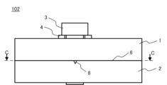
- FIG. 6 is a side view showing a schematic structure of the screw fastening structure 102 according to Embodiment 2.
- FIG. FIG. 7 shows a cross section C--C perpendicular to the axial direction of the screw 3 in FIG. It is a top view.
- FIG. 8 is an enlarged sectional view showing a DD section in FIG.
- the screw fastening structure according to the second embodiment is a structure in which the members to be fastened 1 and 2 are fastened with screws 3, as in the first embodiment.
- the relief portion 7 of the first embodiment is formed at the edge portion 16 of the screw hole 2a in the contact surface 6 of the member 2 to be fastened, whereas the relief portion 8 is formed in the screw fastening structure 102 according to the second embodiment. is formed to extend linearly at the contact surface 6 .
- the relief portion 8 is formed on the contact surface 6 so as to extend from the screw hole 2a.
- One end of the relief portion 8 contacts the adhesive applied to the screw shaft portion 5 in the screw hole 2a, and the other end extends from the screw hole 2a toward the end portion of the member 2 to be fastened.
- the release portion 8 allows the adhesive from the screw shaft portion 5 to escape when the members to be fastened 1 and 2 are tightened. It is processed into a groove shape so as to be recessed inward.
- the relief portion 8 shown in FIGS. 7 and 8 is two straight grooves extending from both sides of the screw hole 2a to the end of the member 2 to be fastened.
- the length, angle, and number of arrangement are not limited to these.
- the contact surface 6 may be formed radially so as to extend toward the end portion of the member 2 to be fastened around the screw hole 2a, or may be formed in a curved shape.
- the cross-sectional shape of the groove of the relief portion 8 is not limited to the triangular concave shape shown in FIG. 8, and may be a square or round concave shape.
- the adhesive can escape and the insulating layer can prevent the occurrence of
- gas-insulated switchgear using the screw fastening structure 102 according to the second embodiment can be configured similarly to the gas-insulated switchgear 100 using the screw fastening structure 101 according to the first embodiment.
- the screw fastening structure according to the second embodiment and the gas-insulated switchgear using this screw fastening structure have the same effects as those of the first embodiment. Furthermore, since the release portion can be linearly extended and made longer, it is possible to release more adhesive than the release portion of the first embodiment. This can further improve the effect of preventing an increase in electrical resistance between fastened conductive components.
- Embodiment 3 In the third embodiment, the same reference numerals are used for the same components as in the first embodiment of the present disclosure, and the description of the same or corresponding parts is omitted.
- a screw fastening structure according to Embodiment 3 will be described with reference to the drawings.
- FIG. 9 is a side view showing a schematic structure of the screw fastening structure 103 according to Embodiment 3.
- FIG. 9A is a side view of the screw fastening structure 103 viewed from the front
- FIG. 9B is a side view of the screw fastening structure 103 viewed from the side.
- the sides shown in FIGS. 9(a) and 9(b) are perpendicular to each other.
- FIG. 10 is a cross-sectional view showing the EE cross section in FIG.
- the screw fastening structure according to the third embodiment has three or more fastening members laminated in the thickness direction. , and is fastened by a plurality of screws 3 from the outside of the surfaces of the members to be fastened that face each other in the thickness direction.
- the inner member to be fastened 12 is sandwiched between the member to be fastened 11 and the member to be fastened 13 on the outer side in the thickness direction. structure.
- Conductive members such as copper and aluminum are used for the members 11, 12 and 13 to be fastened.
- the plurality of screws 3 in the screw fastening structure 103 are, for example, a screw 3a on the member to be fastened 11 side and screws 3b and 3c on the member to be fastened 13 side.
- Screw holes 11a, 12a, and 13a through which the screws 3 pass are formed in the members to be fastened 11, 12, and 13, respectively.
- Fastened members 11, 12, and 13 include screws 3a inserted into screw holes 11a and 12a from the side of the member 11 to be fastened, and screws 3b inserted into the screw holes 13a and 12a from the side of the member 13 to be fastened. , 3c.
- a screw thread is formed on a screw shaft portion 5, which is a shaft portion, and an adhesive (not shown) is applied in advance to each screw thread portion.
- the screw 3a is passed through the locking part 4 and the threaded hole 11a of the member to be fastened 11, and screwed into the threaded hole 12a of the member to be fastened 12, which has been threaded in advance. 12 is concluded. Further, the screws 3b and 3c are respectively passed through the locking portion 4 and the threaded holes 13a of the member 13 to be fastened, and screwed into the other two threaded holes 12a of the member 12 to be threaded in advance. 13 and the member to be fastened 12 are fastened. Thereby, the members to be fastened 11, 12, 13 are fastened.
- both surfaces in the thickness direction of the members to be fastened sandwiched inside are contact surfaces.
- the adhesive from the screw shaft portion 5 escapes when a plurality of members to be fastened is tightened.
- Relief portions 17 formed in a concave shape are provided respectively. That is, when both surfaces of the member to be fastened 12 in the thickness direction are contact surfaces, the relief portions 17 are formed on both surfaces of the member to be fastened 12 .
- Relief portions 17 provided in the members to be fastened 12 are counterbored so as to be recessed inward from the surface in the direction in which the members to be fastened come into contact with each other at the edges 16 of the screw holes 12a on the contact surfaces 6a and 6b. It is formed by being The release portion 17 contacts the adhesive applied to the screw shaft portion 5 and releases excess adhesive from the screw shaft portion 5 to the release portion 17 during tightening, thereby allowing the adhesive to flow between the members 11 and 12 to be fastened. Intrusion into the contact surface 6a and the contact surface 6b between the members 12 and 13 to be fastened is prevented.
- the relief portion 17 may be provided radially outside the screw shaft portion 5 along the entire circumference of the screw hole 12a in the circumferential direction. may be provided only. Further, like the relief portion 7 in the first embodiment, for example, when the relief portion 17 is provided only partially in the circumferential direction of the screw hole 12a, it extends axially along the hole wall of the screw hole 12a, It may be formed so as to pass through the hole 12a.
- the processing method of the relief portion 17 is not limited to counterbore processing, and chamfering processing as shown in FIG. 5 may be used. 10 are formed on the contact surface on the side of the member to be fastened 12, the contact surfaces on the side of the members to be fastened 11, 13 or the respective members to be fastened 11, 12, 13. It may be formed entirely on the contact surface.
- the relief portions 17 are formed intensively on the contact surfaces on both sides of the member to be fastened 12, only one component needs to be processed, leading to cost reduction.
- a gas-insulated switchgear using the screw fastening structure 103 according to the third embodiment can be configured similarly to the gas-insulated switchgear 100 using the screw fastening structure 101 according to the first embodiment.
- the screw fastening structure according to the third embodiment even when multiple layers of the members to be fastened are tightened, excess adhesive from the screw shaft portion is allowed to escape to the release portion, so that the adhesive is applied to the contact surface between the members to be fastened. It is possible to prevent the generation of an insulating layer due to the invasion of the metal and prevent an increase in the electrical resistance between the members to be fastened. Further, according to the gas-insulated switchgear using the screw fastening structure according to the third embodiment, it is possible to prevent an increase in electrical resistance between conductive components fastened in multiple layers, thereby improving efficiency and reliability. can.
- Embodiment 4 In Embodiment 4, the same reference numerals are used for the same components as in Embodiments 2 and 3 of the present disclosure, and descriptions of the same or corresponding portions are omitted.
- a screw fastening structure according to Embodiment 4 will be described with reference to the drawings.
- FIG. 11 is a side view showing a schematic structure of a screw fastening structure 104 according to Embodiment 4.
- FIG. 11(a) is a side view of the screw fastening structure 104 viewed from the front
- FIG. 11(b) is a side view of the screw fastening structure 104 viewed from the side.
- the sides shown in FIGS. 11(a) and 11(b) are perpendicular to each other.
- FIG. 12 shows a FF section and a GG section in FIG. 11(a), and is a plan view of the contact surfaces 6a and 6b on both sides in the thickness direction of the member 12 to be fastened.
- the relief portion 18 for letting the adhesive escape is provided in contrast to the relief portion 17 formed in the edge portion 16 of the screw hole 12a in the screw fastening structure 103 according to the third embodiment. is formed to extend linearly on the contact surface of the member to be fastened 12 .
- the screw fastening structure 104 has a structure in which fastened members 11, 12, and 13 are layered in the thickness direction, similarly to the screw fastening structure 103 according to the third embodiment.
- the fastening method of the screw fastening structure 104 is the same as that of the screw fastening structure 103 according to the third embodiment.
- FIGS. 11 and 12 on the contact surfaces 6a and 6b where the member to be fastened 12 contacts the members to be fastened 11 and 13, respectively, the adhesive from the screw shaft portion 5 is removed when the plurality of members to be fastened are tightened.
- Relief portions 18, which are recessed grooves for relief, are provided respectively.
- the relief portion 18 is formed to contact the adhesive applied to the screw shaft portion 5 and linearly extend from the edge portion 16 of the screw hole 12a. are provided on the surfaces of the
- the contact surfaces 6a and 6b of the member 12 to be fastened have a plurality of screw holes 12a.
- Relief portions 18 provided in the member to be fastened 12 are processed into groove shapes so as to be recessed inward from the surfaces of the contact surfaces 6a and 6b so as to connect the screw holes 12a between the respective screw holes 12a.
- the relief portion 18 is not limited to the shape of the plane and cross section shown in FIGS.
- the groove shape of the relief portion 18 is not limited to the triangular cross section shown in FIG. 11(b), and may be square or circular.
- the contact surfaces 6a and 6b are formed in the same way on the contact surfaces 6a and 6b on the side of the member to be fastened 12, which is easy to process into one part with the same specifications, and has the advantage of reducing costs. be.
- the contact surfaces 6a and 6b may be provided with relief portions having different specifications, if necessary.
- a groove-shaped relief portion and a relief portion counterbored at the edge of the screw hole may be provided. good.
- the relief portions 18 are formed by concentrating on the contact surfaces on both sides of the member to be fastened 12, only one part needs to be processed, leading to cost reduction.
- a gas-insulated switchgear using the screw fastening structure 104 according to the fourth embodiment can be configured similarly to the gas-insulated switchgear 100 using the screw fastening structure 101 according to the first embodiment.
- the screw fastening structure according to the fourth embodiment and the gas-insulated switchgear using this screw fastening structure have the same effects as those of the third embodiment. Furthermore, since the release portion can be linearly extended and made longer, it is possible to release more adhesive than the release portion of the third embodiment. This can further improve the effect of preventing an increase in electrical resistance between conductive components fastened in multiple layers.
- Embodiment 5 In Embodiment 5, the same reference numerals are used for the same components as in Embodiment 1 of the present disclosure, and the description of the same or corresponding parts is omitted.
- a screw fastening structure according to Embodiment 5 will be described with reference to the drawings.
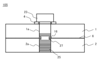
- FIG. 13 is a cross-sectional view showing a schematic structure of a screw fastening structure 105 according to Embodiment 5.
- FIG. 14 is a cross-sectional view showing a schematic structure of the screw 23 in the screw fastening structure 105.
- FIG. 13 and 14 are sectional views parallel to the axial direction of the screw 23.
- the relief portion is provided on the contact surface of the member to be fastened. It becomes the structure provided in the part.
- a screw fastening structure 105 is a structure in which fastened members 1 and 2 are fastened with screws 23 .
- an adhesive (not shown) is applied in advance to a threaded shaft portion 25, which is a shaft portion on which threads are formed.
- the screw shaft portion 25 and the screw holes 1a and 2a are fixed by the adhesive between the screw shaft portion 25 and the screw holes 1a and 2a. This prevents screw loosening.
- the screw 23 is passed through the locking part 4 and the threaded hole 1a of the member to be fastened 1, and screwed into the threaded hole 2a of the member to be fastened 2, which has been threaded in advance. 2 is concluded.
- part of the threaded shaft portion 25 of the screw 23 is preliminarily recessed to provide a relief portion 27 formed in a concave shape.
- the relief portion 27 is formed so as to be recessed radially inward from the surface of the screw shaft portion 25 , and the relief processing position is adjusted so as to face the contact surfaces 6 of the fastened members 1 and 2 .
- the relief portion 27 faces the contact surface 6 of the members to be fastened 1 and 2 and is in contact with the adhesive applied to the screw shaft portion 25 .
- the relief portion facing the position of the contact surface of the member to be fastened means that the relief portion provided in the screw shaft portion is provided at a position corresponding to the contact surface in the axial direction so as to match the height of the contact surface. means that As a result, excess adhesive from the screw shaft portion 25 is allowed to escape to the release portion 27, thereby preventing the adhesive from entering the contact surface 6 between the members 1 and 2 to be fastened.
- the relief portion 27 may be formed over the entire circumference of the screw shaft portion 25 along the circumferential direction, or may be formed only partially in the circumferential direction of the screw shaft portion 25 by adjusting the length.
- the release portion 27 is formed along the entire circumference of the screw shaft portion 25 along the circumferential direction, it is possible to release more adhesive. Further, when the release portion 27 is formed only partially in the circumferential direction of the screw shaft portion 25, it is possible to ensure both the performance of releasing the adhesive and the strength of the screw shaft portion.
- the relief portion 27 is formed along the entire circumference of the screw shaft portion 25 along the circumferential direction, the shape or size of the relief portion 27 differs from that of the thread groove of the screw shaft portion 5 .
- the width is wider compared to the spacing of the thread grooves.
- the depth of the radially inward depression from the surface of the screw shaft portion 25 is greater than that of the thread groove.
- the relief portion 27 may be formed by other cutting processes than the relief process.
- the relief portion 27 of the screw shaft portion 25 may be provided at a position that does not face the contact surface 6 between the member to be fastened 1 and the member to be fastened 2. .
- the adhesive can escape and the occurrence of an insulating layer on the contact surface between the members to be fastened can be prevented. It is possible to further improve the effect of preventing the formation of an insulating layer due to the intrusion of
- a gas-insulated switchgear using the screw fastening structure 105 according to the fifth embodiment can be configured similarly to the gas-insulated switchgear 100 using the screw fastening structure 101 according to the first embodiment.
- the screw fastening structure according to the fifth embodiment and the gas-insulated switchgear using this screw fastening structure have the same effects as those of the first embodiment. Furthermore, compared to processing the relief portion on the contact surface of the member to be fastened in Embodiments 1 to 3, the relief portion of the screw can be easily manufactured by relief processing or the like, and mass production is also possible. Since it can be applied even when processing is difficult due to the size and shape of the member to be fastened, improvement in manufacturing efficiency and cost reduction can be expected.
- Embodiment 6 In Embodiment 6, the same reference numerals are used for the same components as in Embodiments 1 and 5 of the present disclosure, and descriptions of the same or corresponding portions are omitted.
- a screw fastening structure according to Embodiment 6 will be described with reference to the drawings.
- FIG. 15 is a cross-sectional view showing a schematic structure of a screw fastening structure 106 according to Embodiment 6.
- FIG. 16 is a cross-sectional view showing a schematic structure of the screw 33 in the screw fastening structure 106 of FIG. 15.
- FIG. 15 and 16 are sectional views parallel to the axial direction of the screw 33.
- FIG. 17 is a sectional view taken along line HH in FIG. 16 and perpendicular to the axial direction of the screw 33. As shown in FIG.
- the relief portion 27 is provided in the circumferential direction of the screw shaft portion 25.
- the screw fastening structure 106 according to the sixth embodiment includes relief portions for releasing the adhesive. 37 is provided in the axial direction on the screw shaft portion 35 of the screw 33 .
- a screw fastening structure 106 is a structure in which fastened members 1 and 2 are fastened with screws 33 .
- an adhesive (not shown) is applied in advance to a screw shaft portion 35, which is a shaft portion having threads formed thereon.
- the screw shaft portion 35 and the screw holes 1a and 2a are fixed by the adhesive between the screw shaft portion 35 and the screw holes 1a and 2a. This prevents screw loosening.
- the screw 33 is passed through the locking part 4 and the threaded hole 1a of the member to be fastened 1, and screwed into the threaded hole 2a of the member to be fastened 2, which has been threaded in advance. 2 is concluded.
- the threaded shaft portion 35 of the screw 33 is pre-processed to form a groove in the axial direction, and is provided with a recessed relief portion 37 .
- the relief portion 37 is formed on the surface of the screw shaft portion 35 so as to be recessed radially inward from the surface of the screw shaft portion 35 in parallel with the axial direction.
- the relief portion 37 is processed into a groove shape, and the processed position is adjusted so as to face the contact surfaces 6 of the members 1 and 2 to be fastened.
- the relief portion 37 faces the contact surfaces 6 of the members to be fastened 1 and 2 and is in contact with the adhesive applied to the screw shaft portion 35 .
- excess adhesive from the screw shaft portion 35 is allowed to escape to the release portion 37, thereby preventing the adhesive from entering the contact surface 6 between the members 1 and 2 to be fastened.
- the relief portion 37 may be formed over the entire length of the screw shaft portion 35 along the axial direction of the screw shaft portion 35, or may be formed only partially in the axial direction of the screw shaft portion 35 by adjusting the length. .
- the relief portion 37 may be provided at a position not facing the contact surface 6 of the screw shaft portion 25 between the fastened member 1 and the fastened member 2 as long as it contacts the adhesive applied to the screw shaft portion 35 . In this case, the adhesive can escape and the occurrence of an insulating layer on the contact surface between the members to be fastened can be prevented. It is possible to further improve the effect of preventing the formation of an insulating layer due to the intrusion of
- a gas-insulated switchgear using the screw fastening structure 104 according to the fourth embodiment can be configured similarly to the gas-insulated switchgear 100 using the screw fastening structure 101 according to the first embodiment.
- the screw fastening structure according to the sixth embodiment and the gas-insulated switchgear using this screw fastening structure have the same effects as those of the fifth embodiment. Furthermore, since the release portion can be formed up to the maximum length of the shaft portion by being provided in the axial direction of the screw, it is possible to release more adhesive than the release portion of the fifth embodiment. In addition, since the relief portion extends in the axial direction intersecting the contact surface between the members to be fastened, the position can be adjusted according to the height of the contact surface in the axial direction like the relief portion in the fifth embodiment. Even if it is not provided, it can be provided at a position facing the contact surface, which facilitates processing.
Abstract
Provided are a screw fastening structure capable of preventing reduction in conductivity and a gas insulation opening/closing device using this screw fastening structure. A screw fastening structure according to the present disclosure is provided with: a screw (3) that has a screw shaft portion (5) with a screw thread formed; a plurality of fastening subject components (1, 2) that respectively have screw holes (1a, 2a) through which the screw shaft portion (5) passes and that are fastened to each other by the screw (3) inserted in the screw holes (1a, 2a); an adhesive for adhering and fixing the screw shaft portion (5) and the screw holes (1a, 2a) to each other; and a recessed flank portion (7) that is provided at least in one of a contact surface (6) at which the plurality of fastening subject components (1, 2) are in contact with each other and the screw shaft portion (5) and is filled with a portion of the adhesive.
Description
本開示は、ねじ込んだねじを固定するために接着手段を用いた緩み防止のねじ締結構造、および、このねじ締結構造を用いたガス絶縁開閉装置に関するものである。
The present disclosure relates to a looseness-preventing screw fastening structure that uses adhesive means to fix screwed screws, and a gas-insulated switchgear that uses this screw fastening structure.
ねじ締結とは、ねじを用いて2個以上の被締結部材を締め付けて固定することである。ねじの緩み防止の締結構造について、一般的にねじのねじ緩み止め用に、嫌気性接着剤を用い、ねじのねじ山に塗布してねじと機械的に締結された被締結部材との間の隙間を充填することにより緩み防止するように構成している。このような接着剤を塗布する手段は、必要にして充分な最低量の接着剤を常時安定的に塗布するのに熟練を要す。接着剤が少ない場合は、必要なねじ緩み防止性能を得ることができず、接着剤が多い場合は、ねじ締結時に、ねじ山から余った余剰接着剤が流れ出る。流れ出た余剰接着剤が被締結部材同士の間に入り込むと絶縁層ができる。絶縁層が被締結部材の通電部で発生した場合は、絶縁層の面積分の影響で通電面積が減少する。これにより電気抵抗が増加することで発熱量が増え、熱伝導率が低い絶縁層が被締結部材間に介在することで伝熱性能の低下となり、温度上昇基準が定められている電気機器の場合は信頼性能を損なう可能性がある。
Screw fastening is to fasten and fix two or more fastened members using screws. Regarding the fastening structure to prevent the loosening of screws, in general, an anaerobic adhesive is used to prevent the screws from loosening, and is applied to the threads of the screws to seal the screw and the mechanically fastened member. It is configured to prevent loosening by filling the gap. Such means for applying adhesive requires skill to consistently apply the necessary and sufficient minimum amount of adhesive in a stable manner. If the amount of adhesive is too little, the necessary anti-loosening performance cannot be obtained. An insulating layer is formed when the surplus adhesive that has flowed out enters between the members to be fastened. When the insulating layer is generated in the current-carrying portion of the member to be fastened, the current-carrying area is reduced due to the area of the insulating layer. As a result, electrical resistance increases, resulting in an increase in the amount of heat generated, and an insulating layer with low thermal conductivity intervenes between the members to be fastened, resulting in a decrease in heat transfer performance. may impair reliability performance.
特許文献1に開示された締結構造では、接着剤が配置されるテーパー穴およびテーパー穴に連通する溝を有するボルトと、テーパー穴に挿入して溝を押し広げる円錐台状の突起部が内底面に設けられた袋ナットとを利用して、接着剤がテーパー穴から溝へ流れ込むことによりねじ締結の緩みを防止している。
In the fastening structure disclosed in Patent Document 1, a tapered hole in which an adhesive is placed, a bolt having a groove communicating with the tapered hole, and a truncated cone-shaped protrusion that is inserted into the tapered hole and expands the groove are formed on the inner bottom surface. By using a cap nut provided at the end, the adhesive flows into the groove from the tapered hole to prevent loosening of the screw fastening.
しかしながら、特許文献1に記載された締結構造は、締結時にテーパー穴から流れ出た接着剤が被締結部材の間に入り込むことは防げるが、ボルト及びナットにそれぞれ複雑な加工を施す必要がある。また、ガス絶縁開閉装置のような高電圧を扱う機器などでは、構成部品の相間距離の確保や電界集中の緩和対策として被締結部材にねじ切り加工する構造を用いることが多いことから、特許文献1に係る発明のようなボルトとナットとを用いた締結構造は適用しにくい。
However, the fastening structure described in Patent Document 1 can prevent the adhesive flowing out from the tapered hole during fastening from entering between the fastened members, but it is necessary to apply complicated processing to the bolt and nut. In addition, in equipment such as gas-insulated switchgear that handles high voltage, a structure in which the member to be fastened is threaded is often used as a measure to secure the phase-to-phase distance of the component parts and to alleviate the concentration of the electric field. It is difficult to apply a fastening structure using a bolt and a nut as in the invention according to the above.
本開示は、上記のような問題点を解決するためになされたもので、被締結部材をねじによって締結する構造に接着剤が使用される場合、簡潔な構造により被締結部材間の隙間に接着剤の入り込みを防止できるねじ締結構造を提供する。
SUMMARY OF THE INVENTION The present disclosure has been made to solve the above-described problems. Provided is a screw fastening structure capable of preventing the entry of agents.
本開示に係るねじ締結構造は、ねじ山が形成されたねじ軸部を有するねじと、ねじ軸部が貫通するねじ穴をそれぞれ有し、ねじ穴に挿入されたねじによって締結された複数の被締結部材と、ねじ軸部とねじ穴とを固着する接着剤と、複数の被締結部材同士が互いに接触する接触面におけるねじ穴の縁部、および、ねじ軸部の接触面に対向する位置のうち、少なくとも一方に設けられ、接着剤の一部が充填された、凹み状に形成された逃し部とを備える。
本開示に係るガス絶縁開閉装置は、絶縁ガスが封入されている密閉容器と、密閉容器に搭載された遮断器、断路器、母線、およびケーブルを含む構成部品と、を備え、本開示に係るねじ締結構造を用い、複数の構成部品が被締結部材として互いに締結されている。 A screw fastening structure according to the present disclosure has a screw having a screw shaft portion with a thread formed thereon, and a screw hole through which the screw shaft portion passes, and a plurality of covers fastened by the screws inserted into the screw holes. Adhesive for fixing the fastening member, the screw shaft portion and the screw hole, the edge of the screw hole in the contact surface where the plurality of fastened members contact each other, and the position facing the contact surface of the screw shaft portion At least one of them is provided with a recessed relief part filled with a part of the adhesive.
A gas-insulated switchgear according to the present disclosure includes a sealed container in which an insulating gas is sealed, and components including a circuit breaker, a disconnecting switch, a busbar, and a cable mounted in the sealed container. A plurality of components are fastened together as members to be fastened using a screw fastening structure.
本開示に係るねじ締結構造によれば、簡潔な構造により被締結部材間に接着剤の入り込みを防止することができる。これにより、通電性のある被締結部材を締結する場合、被締結部材間に接着剤の入り込みによる導通性能の低下を防止することができる。
本開示に係るねじ締結構造を用いたガス絶縁開閉装置によれば、締結された導電性のある構成部品間の電気抵抗の増加を防止でき、効率と信頼性を高めることができる。 According to the screw fastening structure according to the present disclosure, it is possible to prevent the adhesive from entering between the members to be fastened with a simple structure. As a result, when fastening members having electrical conductivity, it is possible to prevent deterioration of conduction performance due to penetration of the adhesive between the members to be fastened.
According to the gas-insulated switchgear using the screw fastening structure according to the present disclosure, it is possible to prevent an increase in electrical resistance between fastened conductive components, and improve efficiency and reliability.
以下、本開示に係る実施形態について図面を参照して説明する。なお、以下の各実施形態において、同様の構成要素については同一の符号を付している。
Hereinafter, embodiments according to the present disclosure will be described with reference to the drawings. In addition, in each of the following embodiments, the same reference numerals are given to the same components.
実施の形態1.
図1は実施の形態1に係るねじ締結構造を用いたガス絶縁開閉装置の構成例を示す概略断面図である。Embodiment 1.
FIG. 1 is a schematic cross-sectional view showing a configuration example of a gas-insulated switchgear using a screw fastening structure according toEmbodiment 1. FIG.
図1は実施の形態1に係るねじ締結構造を用いたガス絶縁開閉装置の構成例を示す概略断面図である。
FIG. 1 is a schematic cross-sectional view showing a configuration example of a gas-insulated switchgear using a screw fastening structure according to
図1示すように、ガス絶縁開閉装置100は、絶縁ガスが封入されている密閉容器50に遮断器20と、断路器30と、母線40と、ケーブル60を含む構成部品が搭載されている。また、高電圧が印加される主回路部では、遮断器20、断路器30、母線40、ケーブル60などの構成部品が、導体部70によって接続されている。導体部70は、銅やアルミなどの導電性部材が用いられる。ガス絶縁開閉装置100における各構成部品と導体部70との間の接続、および導体部70間の接続は、機器の動作時の衝撃の耐性や導電性、伝熱性の確保が必須となるため、主にねじで締結することが多い。以下、各構成部品および導体部においてねじによって締結される部分を被締結部材として説明する。被締結部材は例えば、構成部品の金属板部である。
図1に示すように、点線で囲まれた部分において被締結部材がねじにより締結されたねじ締結構造101が用いられている。なお、ガス絶縁開閉装置におけるねじ締結構造の配置位置および数はこの限りではない。本開示に係るねじ締結構造は、導電性部材の間の接続に全て適用可能である。 As shown in FIG. 1, the gas-insulatedswitchgear 100 includes components including a circuit breaker 20, a disconnecting switch 30, a busbar 40, and a cable 60 mounted in a sealed container 50 filled with insulating gas. In the main circuit section to which a high voltage is applied, component parts such as the circuit breaker 20 , the disconnecting switch 30 , the busbar 40 and the cable 60 are connected by the conductor section 70 . A conductive member such as copper or aluminum is used for the conductor portion 70 . The connection between each component and the conductor part 70 in the gas-insulated switchgear 100 and the connection between the conductor parts 70 are essential to ensure shock resistance, conductivity, and heat transfer during operation of the device. Fastened mainly with screws. In the following description, portions of the components and conductors that are fastened with screws are referred to as fastened members. The member to be fastened is, for example, a metal plate portion of the component.
As shown in FIG. 1, ascrew fastening structure 101 is used in which a member to be fastened is fastened with a screw in a portion surrounded by a dotted line. In addition, the arrangement position and the number of the screw fastening structures in the gas-insulated switchgear are not limited to this. The screw fastening structure according to the present disclosure is applicable to all connections between conductive members.
図1に示すように、点線で囲まれた部分において被締結部材がねじにより締結されたねじ締結構造101が用いられている。なお、ガス絶縁開閉装置におけるねじ締結構造の配置位置および数はこの限りではない。本開示に係るねじ締結構造は、導電性部材の間の接続に全て適用可能である。 As shown in FIG. 1, the gas-insulated
As shown in FIG. 1, a
次に、ねじ締結構造101の構造について説明する。
図2は実施の形態1に係るねじ締結構造101の概略構造を示す側面図である。図3は図2におけるねじ3の軸部の軸方向に平行するA-A断面を示し、ねじ締結構造101の概略構造を示す断面図である。
以下の説明において、軸方向はねじの軸部に沿った方向を指す。径方向はねじの軸部を中心としたときの半径方向を指す。周方向はねじの回転方向に沿った方向を指す。径方向の内側とは、半径方向において、軸部中心に近づく側である。径方向の外側とは、半径方向において軸部中心から遠ざかる側である。 Next, the structure of thescrew fastening structure 101 will be described.
FIG. 2 is a side view showing a schematic structure of thescrew fastening structure 101 according to Embodiment 1. FIG. 3 is a cross-sectional view showing a schematic structure of the screw fastening structure 101, showing a cross section AA parallel to the axial direction of the shaft portion of the screw 3 in FIG.
In the following description, axial refers to the direction along the shank of the screw. The radial direction refers to the radial direction around the shank of the screw. Circumferential direction refers to the direction along the direction of rotation of the screw. The radially inner side is the side closer to the shaft center in the radial direction. The radially outer side is the side away from the shaft center in the radial direction.
図2は実施の形態1に係るねじ締結構造101の概略構造を示す側面図である。図3は図2におけるねじ3の軸部の軸方向に平行するA-A断面を示し、ねじ締結構造101の概略構造を示す断面図である。
以下の説明において、軸方向はねじの軸部に沿った方向を指す。径方向はねじの軸部を中心としたときの半径方向を指す。周方向はねじの回転方向に沿った方向を指す。径方向の内側とは、半径方向において、軸部中心に近づく側である。径方向の外側とは、半径方向において軸部中心から遠ざかる側である。 Next, the structure of the
FIG. 2 is a side view showing a schematic structure of the
In the following description, axial refers to the direction along the shank of the screw. The radial direction refers to the radial direction around the shank of the screw. Circumferential direction refers to the direction along the direction of rotation of the screw. The radially inner side is the side closer to the shaft center in the radial direction. The radially outer side is the side away from the shaft center in the radial direction.
実施の形態1に係るねじ締結構造101は、被締結部材1、2をねじ3で締め付けている構造である。
被締結部材1、2は、銅、アルミなどの導電性部材が用いられる。被締結部材1、2に、それぞれねじ3が貫通するためのねじ穴1a、2aが形成されている。被締結部材1、2は、ねじ穴に1a、2a挿入されたねじ3によって締結され、被締結部材1、2同士が互いに接触する表面は接触面6である。
ねじ3において、軸部となるねじ軸部5にはねじ山が形成されており、ねじ山の部分に予め接着剤(図示せず)が塗布されている。被締結部材1、2がねじ3によって締め付けられた状態では、ねじ軸部5とねじ穴1a、2aとの間の接着剤によりねじ軸部5とねじ穴1a、2aとが固着される。これによりねじ緩みが防止される。 Ascrew fastening structure 101 according to Embodiment 1 is a structure in which fastened members 1 and 2 are fastened with screws 3 .
Conductive members such as copper and aluminum are used for the members to be fastened 1 and 2 . Screw holes 1a and 2a through which screws 3 pass are formed in the members to be fastened 1 and 2, respectively. The members to be fastened 1 and 2 are fastened by screws 3 inserted into the screw holes 1a and 2a, and the surfaces where the members to be fastened 1 and 2 come into contact with each other are contact surfaces 6. FIG.
In thescrew 3, a screw thread is formed on a screw shaft portion 5, which is a shaft portion, and an adhesive (not shown) is applied in advance to the thread portion. When the members to be fastened 1 and 2 are tightened by the screws 3, the screw shaft portion 5 and the screw holes 1a and 2a are fixed by the adhesive between the screw shaft portion 5 and the screw holes 1a and 2a. This prevents screw loosening.
被締結部材1、2は、銅、アルミなどの導電性部材が用いられる。被締結部材1、2に、それぞれねじ3が貫通するためのねじ穴1a、2aが形成されている。被締結部材1、2は、ねじ穴に1a、2a挿入されたねじ3によって締結され、被締結部材1、2同士が互いに接触する表面は接触面6である。
ねじ3において、軸部となるねじ軸部5にはねじ山が形成されており、ねじ山の部分に予め接着剤(図示せず)が塗布されている。被締結部材1、2がねじ3によって締め付けられた状態では、ねじ軸部5とねじ穴1a、2aとの間の接着剤によりねじ軸部5とねじ穴1a、2aとが固着される。これによりねじ緩みが防止される。 A
Conductive members such as copper and aluminum are used for the members to be fastened 1 and 2 . Screw
In the
締結方法について、ねじ3を係止部4と被締結部材1のねじ穴1aに通し、予めねじ切り加工を施した被締結部材2のねじ穴2aにねじ込むことにより、被締結部材1と被締結部材2を締結する。係止部4は、座金の機能を有している。
Regarding the fastening method, the screw 3 is passed through the locking part 4 and the threaded hole 1a of the member to be fastened 1, and screwed into the threaded hole 2a of the member to be fastened 2, which has been threaded in advance. 2. The locking portion 4 functions as a washer.
図3に示すように、被締結部材2と被締結部材1との接触面6において、ねじ軸部5に塗布された接着剤に接触し、被締結部材1、2が締め付けられる際にねじ軸部5からの接着剤を逃すため凹み状に形成された逃し部7が設けられている。逃し部7は、締め付け時の余剰接着剤を逃し部7に逃すことにより、接着剤が被締結部材1、2間の接触面への侵入を防ぐ。
ここで、逃し部が接着剤に接触するとは、被締結部材がねじ締めにより固定された場合において、逃し部が接着剤の一部に接触している状態、或いは逃し部に流れ込んだ接着剤があり、接着剤の一部が逃し部に充填されていることを含む。以下の説明においても同様である。
図3における一点鎖線で囲まれた領域Bの拡大断面図を図4に示す。図4に示すように、被締結部材2に設けられた逃し部7は、ねじ軸部5の径方向の外側に、被締結部材同士が接触する方向において、被締結部材2の接触面6の表面から内側に凹むように形成されている。逃し部7は、接触面6におけるねじ穴2aの縁部16に、周方向に沿ってザグリ加工が施されることにより形成されている。 As shown in FIG. 3, thecontact surface 6 between the member to be fastened 2 and the member to be fastened 1 contacts the adhesive applied to the screw shaft portion 5, and when the members to be fastened 1 and 2 are tightened, the screw shaft A recessed relief portion 7 is provided to allow the adhesive from the portion 5 to escape. The release portion 7 prevents the adhesive from entering the contact surface between the members 1 and 2 to be fastened by releasing excess adhesive to the release portion 7 during tightening.
Here, the relief part contacts the adhesive means that the relief part is in contact with a part of the adhesive when the member to be fastened is fixed by screwing, or the adhesive that has flowed into the relief part is in contact with the adhesive. Yes, including that part of the adhesive is filled in the relief portion. The same applies to the following description.
FIG. 4 shows an enlarged cross-sectional view of a region B surrounded by a dashed line in FIG. As shown in FIG. 4 , therelief portion 7 provided in the member to be fastened 2 is arranged radially outward of the screw shaft portion 5 so that the contact surface 6 of the member to be fastened 2 extends in the direction in which the members to be fastened come into contact with each other. It is formed so as to be recessed inward from the surface. The relief portion 7 is formed by counterbore processing the edge portion 16 of the screw hole 2a in the contact surface 6 along the circumferential direction.
ここで、逃し部が接着剤に接触するとは、被締結部材がねじ締めにより固定された場合において、逃し部が接着剤の一部に接触している状態、或いは逃し部に流れ込んだ接着剤があり、接着剤の一部が逃し部に充填されていることを含む。以下の説明においても同様である。
図3における一点鎖線で囲まれた領域Bの拡大断面図を図4に示す。図4に示すように、被締結部材2に設けられた逃し部7は、ねじ軸部5の径方向の外側に、被締結部材同士が接触する方向において、被締結部材2の接触面6の表面から内側に凹むように形成されている。逃し部7は、接触面6におけるねじ穴2aの縁部16に、周方向に沿ってザグリ加工が施されることにより形成されている。 As shown in FIG. 3, the
Here, the relief part contacts the adhesive means that the relief part is in contact with a part of the adhesive when the member to be fastened is fixed by screwing, or the adhesive that has flowed into the relief part is in contact with the adhesive. Yes, including that part of the adhesive is filled in the relief portion. The same applies to the following description.
FIG. 4 shows an enlarged cross-sectional view of a region B surrounded by a dashed line in FIG. As shown in FIG. 4 , the
また、図5に逃し部7の変形例となる逃し部7aの拡大断面図を示す。
図5に示すように、被締結部材2の接触面6に、被締結部材1、2が締め付けられる際にねじ軸部5からの接着剤を逃すため凹み状に形成された逃し部7aが設けられている。逃し部7aは、ねじ軸部5の径方向の外側に、ねじ軸部5に塗布された接着剤に接触し、被締結部材同士が接触する方向において、接触面6の表面から内側に凹むように、ねじ穴2aの縁部16に周方向に沿って面取り加工が施されることにより形成されている。面取り加工は簡易にできるだけでなく、面取り加工された被締結部材も扱いやすくなり、安全性が確保できる。 5 shows an enlarged cross-sectional view of arelief portion 7a, which is a modification of the relief portion 7. As shown in FIG.
As shown in FIG. 5, thecontact surface 6 of the member to be fastened 2 is provided with a recessed relief portion 7a for releasing the adhesive from the screw shaft portion 5 when the members to be fastened 1, 2 are tightened. It is The relief portion 7a contacts the adhesive applied to the screw shaft portion 5 on the radially outer side of the screw shaft portion 5, and is recessed inward from the surface of the contact surface 6 in the direction in which the members to be fastened come into contact with each other. 2, the edge 16 of the screw hole 2a is chamfered along the circumferential direction. Not only can chamfering be easily performed, but also the chamfered members to be fastened can be easily handled and safety can be ensured.
図5に示すように、被締結部材2の接触面6に、被締結部材1、2が締め付けられる際にねじ軸部5からの接着剤を逃すため凹み状に形成された逃し部7aが設けられている。逃し部7aは、ねじ軸部5の径方向の外側に、ねじ軸部5に塗布された接着剤に接触し、被締結部材同士が接触する方向において、接触面6の表面から内側に凹むように、ねじ穴2aの縁部16に周方向に沿って面取り加工が施されることにより形成されている。面取り加工は簡易にできるだけでなく、面取り加工された被締結部材も扱いやすくなり、安全性が確保できる。 5 shows an enlarged cross-sectional view of a
As shown in FIG. 5, the
実施の形態1における逃し部は、加工方法が切削によりザグリ加工、面取り加工に限らない。また、図4に示す逃し部7と図5に示す逃し部7aは、接触面6におけるねじ穴2aの縁部16に、ねじ穴2aの周方向に沿って全周に設けられてもよく、周方向において一部のみ設けられても良い。接触面6の面積に影響が少ないため、導電性能へ影響も少ない。また、この場合、逃し部7、7aの軸方向の深さおよび径方向の大きさは必要に応じて変えられる。例えば、逃し部7はねじ穴2aの周方向において一部のみ設けられる場合、軸方向において、ねじ穴2aの穴壁に沿って被締結部材2の厚み方向の全長まで延伸し、ねじ穴2aを貫通するように形成されてもよい。これにより、被締結部材1、2間の導電性能および締結性能を両立させることができる。
また、図4に示す逃し部7と図5に示す逃し部7aは、被締結部材2側に形成されているが、被締結部材1側の接触面もしくは被締結部材1、2の両方の接触面とも形成されてもよい。 The processing method of the relief portion inEmbodiment 1 is not limited to counterbore processing or chamfering by cutting. The relief portion 7 shown in FIG. 4 and the relief portion 7a shown in FIG. It may be provided only partially in the circumferential direction. Since there is little influence on the area of the contact surface 6, there is little influence on the conductive performance. Further, in this case, the axial depth and radial size of the relief portions 7, 7a can be changed as required. For example, when the relief portion 7 is provided only partially in the circumferential direction of the screw hole 2a, it extends along the hole wall of the screw hole 2a to the entire thickness direction of the member 2 to be fastened in the axial direction. It may be formed to penetrate. Thereby, both the conductive performance and the fastening performance between the members to be fastened 1 and 2 can be achieved.
Theescape portion 7 shown in FIG. 4 and the escape portion 7a shown in FIG. 5 are formed on the member to be fastened 2 side. A face may also be formed.
また、図4に示す逃し部7と図5に示す逃し部7aは、被締結部材2側に形成されているが、被締結部材1側の接触面もしくは被締結部材1、2の両方の接触面とも形成されてもよい。 The processing method of the relief portion in
The
なお、ねじ軸部5に塗布された接着剤と接触すれば、逃し部は被締結部材1と被締結部材2との接触面にかからない被締結部材1、2のねじ穴の中に設けられても良い。例えば、ねじ穴の穴壁に一部を切り欠き加工することにより、逃し部として凹み状に形成してもよい。この場合、接着剤を逃すことができ、被締結部材間の接触面に絶縁層の発生を防ぐことができるが、逃し部は被締結部材の接触面におけるねじ穴の縁部に設けられることにより、接触面に接着剤の侵入による絶縁層の発生を防ぐ効果をさらに向上できる。
If the adhesive applied to the screw shaft portion 5 comes into contact with the adhesive, the relief portion is provided in the threaded holes of the members to be fastened 1 and 2 so as not to contact the contact surfaces of the members to be fastened 1 and 2. Also good. For example, by notching a portion of the hole wall of the screw hole, the relief portion may be formed in a concave shape. In this case, the adhesive can escape and the occurrence of an insulating layer on the contact surface between the members to be fastened can be prevented. , the effect of preventing the formation of an insulating layer due to penetration of the adhesive into the contact surface can be further improved.
実施の形態1に係るねじ締結構造によれば、簡潔な構造により被締結部材同士を締め付ける時にねじ軸部からの余剰接着剤を逃し部に逃すことにより被締結部材間の接触面に接着剤の侵入による絶縁層の発生を防ぎ、被締結部材同士間の電気抵抗の増加を防止できる。
また、実施の形態1に係るねじ締結構造を用いたガス絶縁開閉装置によれば、締結された導電性のある構成部品間の電気抵抗増加を防止でき、効率と信頼性を高めることができる。 According to the screw fastening structure according toEmbodiment 1, when the members to be fastened are tightened together, excess adhesive from the screw shank escapes to the escape portion due to the simple structure, so that the adhesive does not reach the contact surface between the members to be fastened. It is possible to prevent the generation of an insulating layer due to penetration and prevent an increase in electrical resistance between members to be fastened.
Further, according to the gas-insulated switchgear using the screw fastening structure according toEmbodiment 1, it is possible to prevent an increase in electrical resistance between fastened conductive components, and to improve efficiency and reliability.
また、実施の形態1に係るねじ締結構造を用いたガス絶縁開閉装置によれば、締結された導電性のある構成部品間の電気抵抗増加を防止でき、効率と信頼性を高めることができる。 According to the screw fastening structure according to
Further, according to the gas-insulated switchgear using the screw fastening structure according to
実施の形態2.
実施の形態2では、本開示の実施の形態1と同一の構成要素には同一の符号を使用し、同一または対応する部分についての説明は省略する。以下、図面を参照して、実施の形態2に係るねじ締結構造について説明する。Embodiment 2.
In the second embodiment, the same reference numerals are used for the same components as in the first embodiment of the present disclosure, and the description of the same or corresponding parts is omitted. Hereinafter, a screw fastening structure according toEmbodiment 2 will be described with reference to the drawings.
実施の形態2では、本開示の実施の形態1と同一の構成要素には同一の符号を使用し、同一または対応する部分についての説明は省略する。以下、図面を参照して、実施の形態2に係るねじ締結構造について説明する。
In the second embodiment, the same reference numerals are used for the same components as in the first embodiment of the present disclosure, and the description of the same or corresponding parts is omitted. Hereinafter, a screw fastening structure according to
図6は実施の形態2に係るねじ締結構造102の概略構造を示す側面図である。図7は図6におけるねじ3の軸方向に垂直するC-C断面を示し、被締結部材2の上方から見た被締結部材1と接触する被締結部材2の接触面6の概略構造を示す平面図である。図8は図7におけるD-D断面を示す拡大断面図である。
FIG. 6 is a side view showing a schematic structure of the screw fastening structure 102 according to Embodiment 2. FIG. FIG. 7 shows a cross section C--C perpendicular to the axial direction of the screw 3 in FIG. It is a top view. FIG. 8 is an enlarged sectional view showing a DD section in FIG.
実施の形態2に係るねじ締結構造は、実施の形態1と同様に、被締結部材1、2をねじ3で締め付けている構造である。実施の形態1の逃し部7は、被締結部材2の接触面6におけるねじ穴2aの縁部16に形成されることに対して、実施の形態2に係るねじ締結構造102では、逃し部8は接触面6において線状に延伸するように形成されている。
The screw fastening structure according to the second embodiment is a structure in which the members to be fastened 1 and 2 are fastened with screws 3, as in the first embodiment. The relief portion 7 of the first embodiment is formed at the edge portion 16 of the screw hole 2a in the contact surface 6 of the member 2 to be fastened, whereas the relief portion 8 is formed in the screw fastening structure 102 according to the second embodiment. is formed to extend linearly at the contact surface 6 .
図7に示すように、逃し部8は、接触面6において、ねじ穴2aを起点に延伸するように形成されている。逃し部8は、一端がねじ穴2aにおいてねじ軸部5に塗布された接着剤に接触し、他端がねじ穴2aから被締結部材2の端部方向に向かって延伸している。
図8に示すように、逃し部8は、被締結部材1、2が締め付けられる際にねじ軸部5からの接着剤を逃すため、被締結部材同士が接触する方向において接触面6の表面から内側に凹むように溝形状に加工されている。 As shown in FIG. 7, therelief portion 8 is formed on the contact surface 6 so as to extend from the screw hole 2a. One end of the relief portion 8 contacts the adhesive applied to the screw shaft portion 5 in the screw hole 2a, and the other end extends from the screw hole 2a toward the end portion of the member 2 to be fastened.
As shown in FIG. 8, therelease portion 8 allows the adhesive from the screw shaft portion 5 to escape when the members to be fastened 1 and 2 are tightened. It is processed into a groove shape so as to be recessed inward.
図8に示すように、逃し部8は、被締結部材1、2が締め付けられる際にねじ軸部5からの接着剤を逃すため、被締結部材同士が接触する方向において接触面6の表面から内側に凹むように溝形状に加工されている。 As shown in FIG. 7, the
As shown in FIG. 8, the
図7、8に示す逃し部8は、ねじ穴2aの両側からそれぞれ被締結部材2の端部まで延伸する2本の直線状の溝となるが、逃し部8の平面と断面の形状、延伸長さと角度、及び配置の本数はこれに限定するものではない。例えば、接触面6において、ねじ穴2aを中心に被締結部材2の端部方向へ延びるように放射状に形成されても良く、曲線状に形成されても良い。また、逃し部8の溝の断面形状について、図8に示す断面が三角形の凹み状に限らず、四角でも丸形の凹み状でも良い。
The relief portion 8 shown in FIGS. 7 and 8 is two straight grooves extending from both sides of the screw hole 2a to the end of the member 2 to be fastened. The length, angle, and number of arrangement are not limited to these. For example, the contact surface 6 may be formed radially so as to extend toward the end portion of the member 2 to be fastened around the screw hole 2a, or may be formed in a curved shape. Further, the cross-sectional shape of the groove of the relief portion 8 is not limited to the triangular concave shape shown in FIG. 8, and may be a square or round concave shape.
また、実施の形態1と同様に、実施の形態2における逃し部8は、被締結部材1、2の少なくとも何れか一方の接触面に形成されると、接着剤を逃すことができ、絶縁層の発生を防ぐことができる。
Further, as in the first embodiment, when the relief portion 8 in the second embodiment is formed on the contact surface of at least one of the members 1 and 2 to be fastened, the adhesive can escape and the insulating layer can prevent the occurrence of
また、実施の形態2に係るねじ締結構造102を用いたガス絶縁開閉装置は、実施の形態1に係るねじ締結構造101を用いたガス絶縁開閉装置100と同様に構成できる。
Also, the gas-insulated switchgear using the screw fastening structure 102 according to the second embodiment can be configured similarly to the gas-insulated switchgear 100 using the screw fastening structure 101 according to the first embodiment.
実施の形態2に係るねじ締結構造およびこのねじ締結構造を用いたガス絶縁開閉装置によれば、実施の形態1と同様な効果を有する。
さらに、逃し部は線状で延伸し、長さが長くできるため、実施の形態1の逃し部より多くの接着剤を逃すことが可能である。これにより、締結された導電性のある構成部品間の電気抵抗増加の防止効果をさらに向上できる。 The screw fastening structure according to the second embodiment and the gas-insulated switchgear using this screw fastening structure have the same effects as those of the first embodiment.
Furthermore, since the release portion can be linearly extended and made longer, it is possible to release more adhesive than the release portion of the first embodiment. This can further improve the effect of preventing an increase in electrical resistance between fastened conductive components.
実施の形態3
実施の形態3では、本開示の実施の形態1と同一の構成要素には同一の符号を使用し、同一または対応する部分についての説明は省略する。以下、図面を参照して、実施の形態3に係るねじ締結構造について説明する。Embodiment 3
In the third embodiment, the same reference numerals are used for the same components as in the first embodiment of the present disclosure, and the description of the same or corresponding parts is omitted. Hereinafter, a screw fastening structure according toEmbodiment 3 will be described with reference to the drawings.
実施の形態3では、本開示の実施の形態1と同一の構成要素には同一の符号を使用し、同一または対応する部分についての説明は省略する。以下、図面を参照して、実施の形態3に係るねじ締結構造について説明する。
In the third embodiment, the same reference numerals are used for the same components as in the first embodiment of the present disclosure, and the description of the same or corresponding parts is omitted. Hereinafter, a screw fastening structure according to
図9は実施の形態3に係るねじ締結構造103の概略構造を示す側面図である。図9(a)はねじ締結構造103を前面からみた側面図となる場合、図9(b)はねじ締結構造103を横からみた側面図となる。図9(a)と図9(b)に示す側面は互いに垂直している。図10は図9(b)におけるE-E断面を示し、ねじ締結構造103の概略構造を示す断面図である。
FIG. 9 is a side view showing a schematic structure of the screw fastening structure 103 according to Embodiment 3. FIG. 9A is a side view of the screw fastening structure 103 viewed from the front, and FIG. 9B is a side view of the screw fastening structure 103 viewed from the side. The sides shown in FIGS. 9(a) and 9(b) are perpendicular to each other. FIG. 10 is a cross-sectional view showing the EE cross section in FIG.
実施の形態1に係るねじ締結構造101における2つの被締結部材がねじ3で締め付けられる構造に対して、実施の形態3に係るねじ締結構造は、3つ以上の被締結部材が厚み方向に積層され、被締結部材の厚み方向に対向する表面の外側から複数個のねじ3により締め付けられている構造となる。
図9、10に示すように、実施の形態3に係るねじ締結構造103は、厚み方向において、内側の被締結部材12は、外側の被締結部材11と被締結部材13により挟まれている積層構造となる。被締結部材11、12、13は、銅、アルミなどの導電性部材が用いられる。
ねじ締結構造103における複数個のねじ3は、例えば被締結部材11側のねじ3a、および被締結部材13側のねじ3b、3cの3つのねじである。被締結部材11、12、13において、それぞれねじ3が貫通するためのねじ穴11a、12a、13aが形成されている。被締結部材11、12、13は、被締結部材11側からねじ穴に11a、12a挿入された挿入されるねじ3a、および、被締結部材13側からねじ穴に13a、12a挿入されたねじ3b、3cによって締め付けられている。
また、各ねじ3において、軸部となるねじ軸部5にはそれぞれねじ山が形成されており、ねじ山の部分にそれぞれ予め接着剤(図示せず)が塗布されている。被締結部材11、12、13が複数のねじ3によって締め付けられた状態では、各々のねじ軸部5とねじ穴11a、12a、13aとの間の接着剤によりねじ軸部5とねじ穴11a、12a、13aとが固着される。これによりねじ緩みが防止される。 In contrast to thescrew fastening structure 101 according to the first embodiment in which two fastening members are fastened with screws 3, the screw fastening structure according to the third embodiment has three or more fastening members laminated in the thickness direction. , and is fastened by a plurality of screws 3 from the outside of the surfaces of the members to be fastened that face each other in the thickness direction.
As shown in FIGS. 9 and 10, in thescrew fastening structure 103 according to the third embodiment, the inner member to be fastened 12 is sandwiched between the member to be fastened 11 and the member to be fastened 13 on the outer side in the thickness direction. structure. Conductive members such as copper and aluminum are used for the members 11, 12 and 13 to be fastened.
The plurality ofscrews 3 in the screw fastening structure 103 are, for example, a screw 3a on the member to be fastened 11 side and screws 3b and 3c on the member to be fastened 13 side. Screw holes 11a, 12a, and 13a through which the screws 3 pass are formed in the members to be fastened 11, 12, and 13, respectively. Fastened members 11, 12, and 13 include screws 3a inserted into screw holes 11a and 12a from the side of the member 11 to be fastened, and screws 3b inserted into the screw holes 13a and 12a from the side of the member 13 to be fastened. , 3c.
In eachscrew 3, a screw thread is formed on a screw shaft portion 5, which is a shaft portion, and an adhesive (not shown) is applied in advance to each screw thread portion. When the members to be fastened 11, 12, 13 are tightened by the plurality of screws 3, the adhesive between the screw shafts 5 and the screw holes 11a, 12a, 13a causes the screw shafts 5 and the screw holes 11a, 11a, 11a, 11a, 11a, 11a 12a and 13a are fixed. This prevents screw loosening.
図9、10に示すように、実施の形態3に係るねじ締結構造103は、厚み方向において、内側の被締結部材12は、外側の被締結部材11と被締結部材13により挟まれている積層構造となる。被締結部材11、12、13は、銅、アルミなどの導電性部材が用いられる。
ねじ締結構造103における複数個のねじ3は、例えば被締結部材11側のねじ3a、および被締結部材13側のねじ3b、3cの3つのねじである。被締結部材11、12、13において、それぞれねじ3が貫通するためのねじ穴11a、12a、13aが形成されている。被締結部材11、12、13は、被締結部材11側からねじ穴に11a、12a挿入された挿入されるねじ3a、および、被締結部材13側からねじ穴に13a、12a挿入されたねじ3b、3cによって締め付けられている。
また、各ねじ3において、軸部となるねじ軸部5にはそれぞれねじ山が形成されており、ねじ山の部分にそれぞれ予め接着剤(図示せず)が塗布されている。被締結部材11、12、13が複数のねじ3によって締め付けられた状態では、各々のねじ軸部5とねじ穴11a、12a、13aとの間の接着剤によりねじ軸部5とねじ穴11a、12a、13aとが固着される。これによりねじ緩みが防止される。 In contrast to the
As shown in FIGS. 9 and 10, in the
The plurality of
In each
締結方法について、ねじ3aを係止部4と被締結部材11のねじ穴11aに通し、予めねじ切り加工を施した被締結部材12のねじ穴12aにねじ込むことにより、被締結部材11と被締結部材12は締結される。また、ねじ3b、3cをそれぞれ係止部4と被締結部材13のねじ穴13aに通し、予めねじ切り加工を施した被締結部材12のほかの2つのねじ穴12aにねじ込むことにより、被締結部材13と被締結部材12は締結される。これにより、被締結部材11、12、13は締結される。
Regarding the fastening method, the screw 3a is passed through the locking part 4 and the threaded hole 11a of the member to be fastened 11, and screwed into the threaded hole 12a of the member to be fastened 12, which has been threaded in advance. 12 is concluded. Further, the screws 3b and 3c are respectively passed through the locking portion 4 and the threaded holes 13a of the member 13 to be fastened, and screwed into the other two threaded holes 12a of the member 12 to be threaded in advance. 13 and the member to be fastened 12 are fastened. Thereby, the members to be fastened 11, 12, 13 are fastened.
実施の形態3では、3つ以上の被締結部材が積層されるため、内側に挟まれる被締結部材は厚み方向の両側の表面とも接触面となる。図10に示すように、被締結部材12が被締結部材11、13とそれぞれ接触する接触面6a、6bにおいて、複数の被締結部材が締め付けられる際にねじ軸部5からの接着剤を逃すため凹み状に形成された逃し部17がそれぞれ設けられている。すなわち、被締結部材12は厚み方向の両側の表面とも接触面となる場合、逃し部17は被締結部材12の両側の表面にそれぞれ形成されている。
In Embodiment 3, since three or more members to be fastened are stacked, both surfaces in the thickness direction of the members to be fastened sandwiched inside are contact surfaces. As shown in FIG. 10, at contact surfaces 6a and 6b where the member to be fastened 12 contacts the members to be fastened 11 and 13, respectively, the adhesive from the screw shaft portion 5 escapes when a plurality of members to be fastened is tightened. Relief portions 17 formed in a concave shape are provided respectively. That is, when both surfaces of the member to be fastened 12 in the thickness direction are contact surfaces, the relief portions 17 are formed on both surfaces of the member to be fastened 12 .
被締結部材12に設けられた逃し部17は、それぞれ接触面6a、6bにおけるねじ穴12aの縁部16に、被締結部材同士が接触する方向において、表面から内側に凹むようにザグリ加工が施されることにより形成されている。逃し部17は、ねじ軸部5に塗布された接着剤に接触し、締め付け時にねじ軸部5からの余剰接着剤を逃し部17に逃すことにより、接着剤が被締結部材11、12間の接触面6a、および被締結部材12、13間の接触面6bへの侵入を防ぐ。
Relief portions 17 provided in the members to be fastened 12 are counterbored so as to be recessed inward from the surface in the direction in which the members to be fastened come into contact with each other at the edges 16 of the screw holes 12a on the contact surfaces 6a and 6b. It is formed by being The release portion 17 contacts the adhesive applied to the screw shaft portion 5 and releases excess adhesive from the screw shaft portion 5 to the release portion 17 during tightening, thereby allowing the adhesive to flow between the members 11 and 12 to be fastened. Intrusion into the contact surface 6a and the contact surface 6b between the members 12 and 13 to be fastened is prevented.
実施の形態1における逃し部7と同様に、逃し部17はねじ軸部5の径方向の外側に、ねじ穴12aの周方向に沿って全周に設けられてもよく、周方向において一部のみ設けられても良い。また、実施の形態1における逃し部7と同様に、例えば、逃し部17はねじ穴12aの周方向において一部のみ設けられる場合、軸方向にねじ穴12aの穴壁に沿って延伸し、ねじ穴12aを貫通するように形成されてもよい。
As with the relief portion 7 in the first embodiment, the relief portion 17 may be provided radially outside the screw shaft portion 5 along the entire circumference of the screw hole 12a in the circumferential direction. may be provided only. Further, like the relief portion 7 in the first embodiment, for example, when the relief portion 17 is provided only partially in the circumferential direction of the screw hole 12a, it extends axially along the hole wall of the screw hole 12a, It may be formed so as to pass through the hole 12a.
また、実施の形態1における逃し部7と同様に、逃し部17は、加工方法がザグリ加工に限定せず、図5に示すような面取り加工でもよい。
また、図10に示す複数の逃し部17は、被締結部材12側の接触面に形成されているが、被締結部材11、13側の接触面もしくは被締結部材11、12、13の各々の接触面に全て形成されてもよい。被締結部材12の両側の接触面に集中して逃し部17を形成する場合、一つの部品のみを加工すればよいので、コスト減につながる。 Further, similarly to therelief portion 7 in the first embodiment, the processing method of the relief portion 17 is not limited to counterbore processing, and chamfering processing as shown in FIG. 5 may be used.
10 are formed on the contact surface on the side of the member to be fastened 12, the contact surfaces on the side of the members to be fastened 11, 13 or the respective members to be fastened 11, 12, 13. It may be formed entirely on the contact surface. When therelief portions 17 are formed intensively on the contact surfaces on both sides of the member to be fastened 12, only one component needs to be processed, leading to cost reduction.
また、図10に示す複数の逃し部17は、被締結部材12側の接触面に形成されているが、被締結部材11、13側の接触面もしくは被締結部材11、12、13の各々の接触面に全て形成されてもよい。被締結部材12の両側の接触面に集中して逃し部17を形成する場合、一つの部品のみを加工すればよいので、コスト減につながる。 Further, similarly to the
10 are formed on the contact surface on the side of the member to be fastened 12, the contact surfaces on the side of the members to be fastened 11, 13 or the respective members to be fastened 11, 12, 13. It may be formed entirely on the contact surface. When the
また、実施の形態3に係るねじ締結構造103を用いたガス絶縁開閉装置は、実施の形態1に係るねじ締結構造101を用いたガス絶縁開閉装置100と同様に構成できる。
Also, a gas-insulated switchgear using the screw fastening structure 103 according to the third embodiment can be configured similarly to the gas-insulated switchgear 100 using the screw fastening structure 101 according to the first embodiment.
実施の形態3に係るねじ締結構造によれば、複数層の被締結部材を締め付ける時においても、ねじ軸部からの余剰接着剤を逃し部に逃すことにより被締結部材間の接触面に接着剤の侵入による絶縁層の発生を防ぎ、被締結部材同士間の電気抵抗の増加を防止できる。
また、実施の形態3に係るねじ締結構造を用いたガス絶縁開閉装置によれば、複数層締結された導電性のある構成部品間の電気抵抗増加を防止でき、効率と信頼性を高めることができる。 According to the screw fastening structure according to the third embodiment, even when multiple layers of the members to be fastened are tightened, excess adhesive from the screw shaft portion is allowed to escape to the release portion, so that the adhesive is applied to the contact surface between the members to be fastened. It is possible to prevent the generation of an insulating layer due to the invasion of the metal and prevent an increase in the electrical resistance between the members to be fastened.
Further, according to the gas-insulated switchgear using the screw fastening structure according to the third embodiment, it is possible to prevent an increase in electrical resistance between conductive components fastened in multiple layers, thereby improving efficiency and reliability. can.
実施の形態4
実施の形態4では、本開示の実施の形態2、3と同一の構成要素には同一の符号を使用し、同一または対応する部分についての説明は省略する。以下、図面を参照して、実施の形態4に係るねじ締結構造について説明する。Embodiment 4
InEmbodiment 4, the same reference numerals are used for the same components as in Embodiments 2 and 3 of the present disclosure, and descriptions of the same or corresponding portions are omitted. Hereinafter, a screw fastening structure according to Embodiment 4 will be described with reference to the drawings.
実施の形態4では、本開示の実施の形態2、3と同一の構成要素には同一の符号を使用し、同一または対応する部分についての説明は省略する。以下、図面を参照して、実施の形態4に係るねじ締結構造について説明する。
In
図11は実施の形態4に係るねじ締結構造104の概略構造を示す側面図である。図11(a)はねじ締結構造104を前面からみた側面図となる場合、図11(b)はねじ締結構造104を横からみた側面図となる。図11(a)と図11(b)に示す側面は互いに垂直している。図12は図11(a)におけるF-F断面とG-G断面を示し、被締結部材12の厚み方向両側の接触面6a、6bの平面図である。
FIG. 11 is a side view showing a schematic structure of a screw fastening structure 104 according to Embodiment 4. FIG. 11(a) is a side view of the screw fastening structure 104 viewed from the front, and FIG. 11(b) is a side view of the screw fastening structure 104 viewed from the side. The sides shown in FIGS. 11(a) and 11(b) are perpendicular to each other. FIG. 12 shows a FF section and a GG section in FIG. 11(a), and is a plan view of the contact surfaces 6a and 6b on both sides in the thickness direction of the member 12 to be fastened.
実施の形態3に係るねじ締結構造103におけるねじ穴12aの縁部16に形成された逃し部17に対して、実施の形態4に係るねじ締結構造104では、接着剤を逃すための逃し部18は、被締結部材12の接触面において線状に延伸するように形成されている。
In the screw fastening structure 104 according to the fourth embodiment, the relief portion 18 for letting the adhesive escape is provided in contrast to the relief portion 17 formed in the edge portion 16 of the screw hole 12a in the screw fastening structure 103 according to the third embodiment. is formed to extend linearly on the contact surface of the member to be fastened 12 .
図11に示すように、ねじ締結構造104は実施の形態3に係るねじ締結構造103と同様に、被締結部材11、12、13が厚み方向に積層された構造となる。ねじ締結構造104の締結方法は実施の形態3に係るねじ締結構造103と同様である。
図11、12に示すように、被締結部材12が被締結部材11、13とそれぞれ接触する接触面6a、6bにおいて、複数の被締結部材が締め付けられる際にねじ軸部5からの接着剤を逃すための凹み状の溝となる逃し部18がそれぞれ設けられている。逃し部18は、ねじ軸部5に塗布された接着剤に接触し、ねじ穴12aの縁部16を起点に線状に延伸するように形成されており、被締結部材12の厚み方向の両側の表面にそれぞれ設けられている。 As shown in FIG. 11, thescrew fastening structure 104 has a structure in which fastened members 11, 12, and 13 are layered in the thickness direction, similarly to the screw fastening structure 103 according to the third embodiment. The fastening method of the screw fastening structure 104 is the same as that of the screw fastening structure 103 according to the third embodiment.
As shown in FIGS. 11 and 12, on the contact surfaces 6a and 6b where the member to be fastened 12 contacts the members to be fastened 11 and 13, respectively, the adhesive from thescrew shaft portion 5 is removed when the plurality of members to be fastened are tightened. Relief portions 18, which are recessed grooves for relief, are provided respectively. The relief portion 18 is formed to contact the adhesive applied to the screw shaft portion 5 and linearly extend from the edge portion 16 of the screw hole 12a. are provided on the surfaces of the
図11、12に示すように、被締結部材12が被締結部材11、13とそれぞれ接触する接触面6a、6bにおいて、複数の被締結部材が締め付けられる際にねじ軸部5からの接着剤を逃すための凹み状の溝となる逃し部18がそれぞれ設けられている。逃し部18は、ねじ軸部5に塗布された接着剤に接触し、ねじ穴12aの縁部16を起点に線状に延伸するように形成されており、被締結部材12の厚み方向の両側の表面にそれぞれ設けられている。 As shown in FIG. 11, the
As shown in FIGS. 11 and 12, on the contact surfaces 6a and 6b where the member to be fastened 12 contacts the members to be fastened 11 and 13, respectively, the adhesive from the
また、図12に示すように、被締結部材12の接触面6a、6bにおいて、ねじ穴12aが複数有する。被締結部材12に設けられた逃し部18は、各ねじ穴12aの間に、ねじ穴12aを繋ぐように、接触面6a、6bの表面から内側に凹むように溝形状に加工されている。
Further, as shown in FIG. 12, the contact surfaces 6a and 6b of the member 12 to be fastened have a plurality of screw holes 12a. Relief portions 18 provided in the member to be fastened 12 are processed into groove shapes so as to be recessed inward from the surfaces of the contact surfaces 6a and 6b so as to connect the screw holes 12a between the respective screw holes 12a.
図7に示す実施の形態2に係るねじ締結構造102における逃し部8について、1つのねじ穴に対して溝加工を2か所に施す場合、3つのねじ穴では6か所の溝形状の加工が必要である。これに対して、図12に示すねじ締結構造104に設けられた逃し部18では、ねじ穴12aの間を繋ぐように溝形状の加工を施すことにより、3つのねじ穴に対して4か所の溝形状の加工でねじ軸部からの余剰接着剤を逃すことができる。接着剤を逃す性能が確保されると同時に、加工数が削減できる。
Regarding the escape portion 8 in the screw fastening structure 102 according to Embodiment 2 shown in FIG. is necessary. On the other hand, in the relief portion 18 provided in the screw fastening structure 104 shown in FIG. Excess adhesive from the screw shaft can be released by processing the groove shape. The number of processes can be reduced at the same time as securing the ability to release the adhesive.
なお、実施の形態2における逃し部8と同様に、逃し部18は図11、12に示す平面と断面の形状、延伸長さと角度、及び配置の本数はこれに限定するものではない。例えば、逃し部18の溝形状について、図11(b)に示す断面が三角形状に限らず、四角でも丸形状でも良い。
As with the relief portion 8 in Embodiment 2, the relief portion 18 is not limited to the shape of the plane and cross section shown in FIGS. For example, the groove shape of the relief portion 18 is not limited to the triangular cross section shown in FIG. 11(b), and may be square or circular.
また、図12に示す複数の逃し部18は、被締結部材12側の接触面6a、6bにおいて同じように形成されており、一つの部品に同じ仕様で加工しやすく、コスト減につながる利点がある。なお、必要に応じて接触面6a、6bにそれぞれ異なる仕様の逃し部を設けても良い。また、例えば、実施の形態3と組み合わせ、中間層となる被締結部材の2つの接触面において、溝形状の逃し部とねじ穴の縁部にザグリ加工された逃し部とがそれぞれ設けられてもよい。
12 are formed in the same way on the contact surfaces 6a and 6b on the side of the member to be fastened 12, which is easy to process into one part with the same specifications, and has the advantage of reducing costs. be. It should be noted that the contact surfaces 6a and 6b may be provided with relief portions having different specifications, if necessary. Further, for example, in combination with Embodiment 3, on the two contact surfaces of the member to be fastened that serves as an intermediate layer, a groove-shaped relief portion and a relief portion counterbored at the edge of the screw hole may be provided. good.
また、被締結部材11、13側の接触面もしくは被締結部材11、12、13の各々の接触面に全て形成されてもよい。被締結部材12の両側の接触面に集中して逃し部18を形成する場合、一つの部品のみを加工すればよいので、コスト減につながる。
Further, it may be formed entirely on the contact surfaces of the members to be fastened 11, 13 or on the contact surfaces of the members to be fastened 11, 12, 13. When the relief portions 18 are formed by concentrating on the contact surfaces on both sides of the member to be fastened 12, only one part needs to be processed, leading to cost reduction.
また、実施の形態4に係るねじ締結構造104を用いたガス絶縁開閉装置は、実施の形態1に係るねじ締結構造101を用いたガス絶縁開閉装置100と同様に構成できる。
Also, a gas-insulated switchgear using the screw fastening structure 104 according to the fourth embodiment can be configured similarly to the gas-insulated switchgear 100 using the screw fastening structure 101 according to the first embodiment.
実施の形態4に係るねじ締結構造およびこのねじ締結構造を用いたガス絶縁開閉装置によれば、実施の形態3と同様な効果を有する。
さらに、逃し部は線状で延伸し、長さが長くできるため、実施の形態3の逃し部より多くの接着剤を逃すことが可能である。これにより、複数層締結された導電性のある構成部品間の電気抵抗増加の防止効果をさらに向上できる。 The screw fastening structure according to the fourth embodiment and the gas-insulated switchgear using this screw fastening structure have the same effects as those of the third embodiment.
Furthermore, since the release portion can be linearly extended and made longer, it is possible to release more adhesive than the release portion of the third embodiment. This can further improve the effect of preventing an increase in electrical resistance between conductive components fastened in multiple layers.
実施の形態5
実施の形態5では、本開示の実施の形態1と同一の構成要素には同一の符号を使用し、同一または対応する部分についての説明は省略する。以下、図面を参照して、実施の形態5に係るねじ締結構造について説明する。Embodiment 5
InEmbodiment 5, the same reference numerals are used for the same components as in Embodiment 1 of the present disclosure, and the description of the same or corresponding parts is omitted. Hereinafter, a screw fastening structure according to Embodiment 5 will be described with reference to the drawings.
実施の形態5では、本開示の実施の形態1と同一の構成要素には同一の符号を使用し、同一または対応する部分についての説明は省略する。以下、図面を参照して、実施の形態5に係るねじ締結構造について説明する。
In
図13は実施の形態5に係るねじ締結構造105の概略構造を示す断面図である。図14はねじ締結構造105におけるねじ23の概略構造を示す断面図である。図13、14はねじ23の軸方向に平行する断面図となる。
実施の形態1に係るねじ締結構造101における逃し部が被締結部材の接触面設けられる構造に対して、実施の形態5に係るねじ締結構造105は、接着剤を逃すための逃し部がねじ軸部に設けられている構造となる。 FIG. 13 is a cross-sectional view showing a schematic structure of ascrew fastening structure 105 according to Embodiment 5. As shown in FIG. FIG. 14 is a cross-sectional view showing a schematic structure of the screw 23 in the screw fastening structure 105. As shown in FIG. 13 and 14 are sectional views parallel to the axial direction of the screw 23. FIG.
In thescrew fastening structure 101 according to the first embodiment, the relief portion is provided on the contact surface of the member to be fastened. It becomes the structure provided in the part.
実施の形態1に係るねじ締結構造101における逃し部が被締結部材の接触面設けられる構造に対して、実施の形態5に係るねじ締結構造105は、接着剤を逃すための逃し部がねじ軸部に設けられている構造となる。 FIG. 13 is a cross-sectional view showing a schematic structure of a
In the
図13に示すように、実施の形態5に係るねじ締結構造105は、被締結部材1、2をねじ23で締め付けている構造である。ねじ23において、ねじ山が形成された軸部となるねじ軸部25には、予め接着剤(図示せず)が塗布されている。被締結部材1、2がねじ23によって締め付けられた状態では、ねじ軸部25とねじ穴1a、2aとの間の接着剤によりねじ軸部25とねじ穴1a、2aとが固着される。これによりねじ緩みが防止される。
As shown in FIG. 13 , a screw fastening structure 105 according to Embodiment 5 is a structure in which fastened members 1 and 2 are fastened with screws 23 . In the screw 23, an adhesive (not shown) is applied in advance to a threaded shaft portion 25, which is a shaft portion on which threads are formed. When the members to be fastened 1 and 2 are tightened by the screws 23, the screw shaft portion 25 and the screw holes 1a and 2a are fixed by the adhesive between the screw shaft portion 25 and the screw holes 1a and 2a. This prevents screw loosening.
締結方法について、ねじ23を係止部4と被締結部材1のねじ穴1aに通し、予めねじ切り加工を施した被締結部材2のねじ穴2aにねじ込むことにより、被締結部材1と被締結部材2は締結される。
Regarding the fastening method, the screw 23 is passed through the locking part 4 and the threaded hole 1a of the member to be fastened 1, and screwed into the threaded hole 2a of the member to be fastened 2, which has been threaded in advance. 2 is concluded.
図13、14に示すように、ねじ23のねじ軸部25の一部には予めぬすみ加工が施され、凹み状に形成された逃し部27が設けられている。逃し部27は、ねじ軸部25の表面から径方向の内側に凹むように形成されており、被締結部材1、2の接触面6に対向するようにぬすみ加工の位置が調整される。被締結部材1、2を締め付ける際に、逃し部27は、被締結部材1、2の接触面6の位置に対向し、ねじ軸部25に塗布された接着剤に接触している。
ここで、逃し部は被締結部材の接触面の位置に対向するとは、ねじ軸部に設けられた逃し部は、軸方向において接触面の高さに合わせ、接触面に対応する位置に設けられることを意味する。これにより、ねじ軸部25からの余剰接着剤を逃し部27に逃すことにより、接着剤が被締結部材1、2間の接触面6への侵入を防ぐ。 As shown in FIGS. 13 and 14, part of the threadedshaft portion 25 of the screw 23 is preliminarily recessed to provide a relief portion 27 formed in a concave shape. The relief portion 27 is formed so as to be recessed radially inward from the surface of the screw shaft portion 25 , and the relief processing position is adjusted so as to face the contact surfaces 6 of the fastened members 1 and 2 . When the members to be fastened 1 and 2 are tightened, the relief portion 27 faces the contact surface 6 of the members to be fastened 1 and 2 and is in contact with the adhesive applied to the screw shaft portion 25 .
Here, the relief portion facing the position of the contact surface of the member to be fastened means that the relief portion provided in the screw shaft portion is provided at a position corresponding to the contact surface in the axial direction so as to match the height of the contact surface. means that As a result, excess adhesive from thescrew shaft portion 25 is allowed to escape to the release portion 27, thereby preventing the adhesive from entering the contact surface 6 between the members 1 and 2 to be fastened.
ここで、逃し部は被締結部材の接触面の位置に対向するとは、ねじ軸部に設けられた逃し部は、軸方向において接触面の高さに合わせ、接触面に対応する位置に設けられることを意味する。これにより、ねじ軸部25からの余剰接着剤を逃し部27に逃すことにより、接着剤が被締結部材1、2間の接触面6への侵入を防ぐ。 As shown in FIGS. 13 and 14, part of the threaded
Here, the relief portion facing the position of the contact surface of the member to be fastened means that the relief portion provided in the screw shaft portion is provided at a position corresponding to the contact surface in the axial direction so as to match the height of the contact surface. means that As a result, excess adhesive from the
逃し部27は、ねじ軸部25の周方向に沿って全周にわたって形成されてもよく、長さを調整してねじ軸部25の周方向の一部のみ形成されてもよい。逃し部27はねじ軸部25の周方向に沿って全周に形成される場合、より多くの接着剤を逃すことが可能である。また、逃し部27はねじ軸部25の周方向の一部のみ形成される場合、接着剤を逃す性能とねじ軸部の強度とも確保できる。
逃し部27はねじ軸部25の周方向に沿って全周に形成される場合、ねじ軸部5のねじ山の溝に比べて、形状または大きさが異なる。例えば、軸方向において、ねじ山の溝の間隔に比べて、幅がより広い。或は、径方向において、ねじ山の溝に比べて、ねじ軸部25の表面から径方向の内側に凹む深さがより大きい。
また、逃し部27は、ぬすみ加工に限らず、ほかの切削加工により形成されてもよい。 Therelief portion 27 may be formed over the entire circumference of the screw shaft portion 25 along the circumferential direction, or may be formed only partially in the circumferential direction of the screw shaft portion 25 by adjusting the length. When the release portion 27 is formed along the entire circumference of the screw shaft portion 25 along the circumferential direction, it is possible to release more adhesive. Further, when the release portion 27 is formed only partially in the circumferential direction of the screw shaft portion 25, it is possible to ensure both the performance of releasing the adhesive and the strength of the screw shaft portion.
When therelief portion 27 is formed along the entire circumference of the screw shaft portion 25 along the circumferential direction, the shape or size of the relief portion 27 differs from that of the thread groove of the screw shaft portion 5 . For example, in the axial direction the width is wider compared to the spacing of the thread grooves. Alternatively, in the radial direction, the depth of the radially inward depression from the surface of the screw shaft portion 25 is greater than that of the thread groove.
Also, therelief portion 27 may be formed by other cutting processes than the relief process.
逃し部27はねじ軸部25の周方向に沿って全周に形成される場合、ねじ軸部5のねじ山の溝に比べて、形状または大きさが異なる。例えば、軸方向において、ねじ山の溝の間隔に比べて、幅がより広い。或は、径方向において、ねじ山の溝に比べて、ねじ軸部25の表面から径方向の内側に凹む深さがより大きい。
また、逃し部27は、ぬすみ加工に限らず、ほかの切削加工により形成されてもよい。 The
When the
Also, the
なお、ねじ軸部25に塗布された接着剤と接触すれば、ねじ軸部25の逃し部27は被締結部材1と被締結部材2との接触面6に対向しない位置に設けられてもよい。この場合、接着剤を逃すことができ、被締結部材間の接触面に絶縁層の発生を防ぐことができるが、逃し部は接触面に対向する位置に設けられることにより、接触面に接着剤の侵入による絶縁層の発生を防ぐ効果をさらに向上できる。
In addition, if contact is made with the adhesive applied to the screw shaft portion 25, the relief portion 27 of the screw shaft portion 25 may be provided at a position that does not face the contact surface 6 between the member to be fastened 1 and the member to be fastened 2. . In this case, the adhesive can escape and the occurrence of an insulating layer on the contact surface between the members to be fastened can be prevented. It is possible to further improve the effect of preventing the formation of an insulating layer due to the intrusion of
また、実施の形態5に係るねじ締結構造105を用いたガス絶縁開閉装置は、実施の形態1に係るねじ締結構造101を用いたガス絶縁開閉装置100と同様に構成できる。
Also, a gas-insulated switchgear using the screw fastening structure 105 according to the fifth embodiment can be configured similarly to the gas-insulated switchgear 100 using the screw fastening structure 101 according to the first embodiment.
実施の形態5に係るねじ締結構造およびこのねじ締結構造を用いたガス絶縁開閉装置によれば、実施の形態1と同様な効果を有する。
さらに、実施の形態1から3における被締結部材の接触面に逃し部を加工することに比べて、ねじにおける逃し部はぬすみ加工等によって容易に作製でき、量産も可能である。被締結部材のサイズと形状により加工が難しい場合にも適用できるため、製造効率の向上およびコスト削減が期待できる。 The screw fastening structure according to the fifth embodiment and the gas-insulated switchgear using this screw fastening structure have the same effects as those of the first embodiment.
Furthermore, compared to processing the relief portion on the contact surface of the member to be fastened inEmbodiments 1 to 3, the relief portion of the screw can be easily manufactured by relief processing or the like, and mass production is also possible. Since it can be applied even when processing is difficult due to the size and shape of the member to be fastened, improvement in manufacturing efficiency and cost reduction can be expected.
さらに、実施の形態1から3における被締結部材の接触面に逃し部を加工することに比べて、ねじにおける逃し部はぬすみ加工等によって容易に作製でき、量産も可能である。被締結部材のサイズと形状により加工が難しい場合にも適用できるため、製造効率の向上およびコスト削減が期待できる。 The screw fastening structure according to the fifth embodiment and the gas-insulated switchgear using this screw fastening structure have the same effects as those of the first embodiment.
Furthermore, compared to processing the relief portion on the contact surface of the member to be fastened in
実施の形態6
実施の形態6では、本開示の実施の形態1、5と同一の構成要素には同一の符号を使用し、同一または対応する部分についての説明は省略する。以下、図面を参照して、実施の形態6に係るねじ締結構造について説明する。Embodiment 6
InEmbodiment 6, the same reference numerals are used for the same components as in Embodiments 1 and 5 of the present disclosure, and descriptions of the same or corresponding portions are omitted. Hereinafter, a screw fastening structure according to Embodiment 6 will be described with reference to the drawings.
実施の形態6では、本開示の実施の形態1、5と同一の構成要素には同一の符号を使用し、同一または対応する部分についての説明は省略する。以下、図面を参照して、実施の形態6に係るねじ締結構造について説明する。
In
図15は実施の形態6に係るねじ締結構造106の概略構造を示す断面図である。図16は図15のねじ締結構造106におけるねじ33の概略構造を示す断面図である。図15、16はねじ33の軸方向に平行する断面図となる。また、図17は図16におけるH-H断面を示し、ねじ33の軸方向に垂直する断面図である。
FIG. 15 is a cross-sectional view showing a schematic structure of a screw fastening structure 106 according to Embodiment 6. FIG. 16 is a cross-sectional view showing a schematic structure of the screw 33 in the screw fastening structure 106 of FIG. 15. FIG. 15 and 16 are sectional views parallel to the axial direction of the screw 33. FIG. 17 is a sectional view taken along line HH in FIG. 16 and perpendicular to the axial direction of the screw 33. As shown in FIG.
実施の形態5に係るねじ締結構造105における逃し部27はねじ軸部25において周方向に設けられる構造に対して、実施の形態6に係るねじ締結構造106は、接着剤を逃すための逃し部37がねじ33のねじ軸部35において軸方向に設けられている構造となる。
In the screw fastening structure 105 according to the fifth embodiment, the relief portion 27 is provided in the circumferential direction of the screw shaft portion 25. In contrast, the screw fastening structure 106 according to the sixth embodiment includes relief portions for releasing the adhesive. 37 is provided in the axial direction on the screw shaft portion 35 of the screw 33 .
図15に示すように、実施の形態6に係るねじ締結構造106は、被締結部材1、2をねじ33で締め付けている構造である。ねじ33において、ねじ山が形成された軸部となるねじ軸部35には、予め接着剤(図示せず)が塗布されている。被締結部材1、2がねじ33によって締め付けられた状態では、ねじ軸部35とねじ穴1a、2aとの間の接着剤によりねじ軸部35とねじ穴1a、2aとが固着される。これによりねじ緩みが防止される。
As shown in FIG. 15 , a screw fastening structure 106 according to Embodiment 6 is a structure in which fastened members 1 and 2 are fastened with screws 33 . In the screw 33, an adhesive (not shown) is applied in advance to a screw shaft portion 35, which is a shaft portion having threads formed thereon. When the members to be fastened 1 and 2 are tightened by the screws 33, the screw shaft portion 35 and the screw holes 1a and 2a are fixed by the adhesive between the screw shaft portion 35 and the screw holes 1a and 2a. This prevents screw loosening.
締結方法について、ねじ33を係止部4と被締結部材1のねじ穴1aに通し、予めねじ切り加工を施した被締結部材2のねじ穴2aにねじ込むことにより、被締結部材1と被締結部材2は締結される。
Regarding the fastening method, the screw 33 is passed through the locking part 4 and the threaded hole 1a of the member to be fastened 1, and screwed into the threaded hole 2a of the member to be fastened 2, which has been threaded in advance. 2 is concluded.
図16、17に示すように、ねじ33のねじ軸部35には予め軸方向に溝を形成する加工が施され、凹み状に形成された逃し部37が設けられている。逃し部37は、ねじ軸部35の表面において、軸方向に平行してねじ軸部35の表面から径方向の内側に凹むように形成されている。逃し部37は、溝形状に加工されており、被締結部材1、2の接触面6に対向するように加工の位置が調整される。被締結部材1、2が締め付けられる状態において、逃し部37は、被締結部材1、2の接触面6の位置に対向し、ねじ軸部35に塗布された接着剤に接触している。これにより、ねじ軸部35からの余剰接着剤を逃し部37に逃すことにより、接着剤が被締結部材1、2間の接触面6への侵入を防ぐ。
As shown in FIGS. 16 and 17, the threaded shaft portion 35 of the screw 33 is pre-processed to form a groove in the axial direction, and is provided with a recessed relief portion 37 . The relief portion 37 is formed on the surface of the screw shaft portion 35 so as to be recessed radially inward from the surface of the screw shaft portion 35 in parallel with the axial direction. The relief portion 37 is processed into a groove shape, and the processed position is adjusted so as to face the contact surfaces 6 of the members 1 and 2 to be fastened. When the members to be fastened 1 and 2 are tightened, the relief portion 37 faces the contact surfaces 6 of the members to be fastened 1 and 2 and is in contact with the adhesive applied to the screw shaft portion 35 . As a result, excess adhesive from the screw shaft portion 35 is allowed to escape to the release portion 37, thereby preventing the adhesive from entering the contact surface 6 between the members 1 and 2 to be fastened.
逃し部37は、ねじ軸部35の軸方向に沿ってねじ軸部35の全長にわたって形成されてもよく、長さを調整してねじ軸部35の軸方向の一部のみ形成されてもよい。
逃し部37は、ねじ軸部35に塗布された接着剤と接触すれば、ねじ軸部25の被締結部材1と被締結部材2との接触面6に対向しない位置に設けられてもよい。この場合、接着剤を逃すことができ、被締結部材間の接触面に絶縁層の発生を防ぐことができるが、逃し部は接触面に対向する位置に設けられることにより、接触面に接着剤の侵入による絶縁層の発生を防ぐ効果をさらに向上できる。 Therelief portion 37 may be formed over the entire length of the screw shaft portion 35 along the axial direction of the screw shaft portion 35, or may be formed only partially in the axial direction of the screw shaft portion 35 by adjusting the length. .
Therelief portion 37 may be provided at a position not facing the contact surface 6 of the screw shaft portion 25 between the fastened member 1 and the fastened member 2 as long as it contacts the adhesive applied to the screw shaft portion 35 . In this case, the adhesive can escape and the occurrence of an insulating layer on the contact surface between the members to be fastened can be prevented. It is possible to further improve the effect of preventing the formation of an insulating layer due to the intrusion of
逃し部37は、ねじ軸部35に塗布された接着剤と接触すれば、ねじ軸部25の被締結部材1と被締結部材2との接触面6に対向しない位置に設けられてもよい。この場合、接着剤を逃すことができ、被締結部材間の接触面に絶縁層の発生を防ぐことができるが、逃し部は接触面に対向する位置に設けられることにより、接触面に接着剤の侵入による絶縁層の発生を防ぐ効果をさらに向上できる。 The
The
また、実施の形態4に係るねじ締結構造104を用いたガス絶縁開閉装置は、実施の形態1に係るねじ締結構造101を用いたガス絶縁開閉装置100と同様に構成できる。
Also, a gas-insulated switchgear using the screw fastening structure 104 according to the fourth embodiment can be configured similarly to the gas-insulated switchgear 100 using the screw fastening structure 101 according to the first embodiment.
実施の形態6に係るねじ締結構造およびこのねじ締結構造を用いたガス絶縁開閉装置によれば、実施の形態5と同様な効果を有する。
さらに、逃し部はねじの軸方向に設けられることにより軸部の最大長さまで形成できるため、実施の形態5の逃し部より多くの接着剤を逃すことが可能である。また、逃し部は、被締結部材間の接触面に交差する軸方向に延伸しているため、実施の形態5における逃し部のように軸方向における接触面の高さに合わせて位置を調整しなくても、接触面に対向する位置に設けられることができるので、加工が容易になる。 The screw fastening structure according to the sixth embodiment and the gas-insulated switchgear using this screw fastening structure have the same effects as those of the fifth embodiment.
Furthermore, since the release portion can be formed up to the maximum length of the shaft portion by being provided in the axial direction of the screw, it is possible to release more adhesive than the release portion of the fifth embodiment. In addition, since the relief portion extends in the axial direction intersecting the contact surface between the members to be fastened, the position can be adjusted according to the height of the contact surface in the axial direction like the relief portion in the fifth embodiment. Even if it is not provided, it can be provided at a position facing the contact surface, which facilitates processing.
なお、以上の実施の形態に示した構成は、本開示の内容の一例を示すものであり、実施の形態の間の組み合わせ、および別の公知の技術と組み合わせることも可能であるし、本開示の要旨を逸脱しない範囲で、構成の一部を省略、変更することも可能である。
Note that the configurations shown in the above embodiments are examples of the contents of the present disclosure, and combinations between the embodiments and other known techniques are possible, and the present disclosure It is also possible to omit or change part of the configuration without departing from the gist of the above.
1、2、11、12、13 被締結部材、1a、2a、11a、12a、13a ねじ穴、3、3a、3b、23、33 ねじ、4 係止部、5、25、35 ねじ軸部、6、6a、6b 接触面、7、7a、8、17、18、27、37 逃し部、20 遮断器、30 断路器、40 母線、50 密閉容器、60 ケーブル、70 導体部、100 ガス絶縁開閉装置、101、102、103、104、105、106 ねじ締結構造
1, 2, 11, 12, 13 members to be fastened, 1a, 2a, 11a, 12a, 13a screw holes, 3, 3a, 3b, 23, 33 screws, 4 locking parts, 5, 25, 35 screw shafts, 6, 6a, 6b contact surface, 7, 7a, 8, 17, 18, 27, 37 escape part, 20 circuit breaker, 30 disconnector, 40 busbar, 50 sealed container, 60 cable, 70 conductor part, 100 gas insulated switching Device, 101, 102, 103, 104, 105, 106 Screw fastening structure
Claims (12)
- ねじ山が形成されたねじ軸部を有するねじと、
前記ねじ軸部が貫通するねじ穴をそれぞれ有し、前記ねじ穴に挿入された前記ねじによって締結された複数の被締結部材と、
前記ねじ軸部と前記ねじ穴とを固着する接着剤と、
複数の前記被締結部材同士が互いに接触する接触面における前記ねじ穴の縁部、および、前記ねじ軸部の前記接触面に対向する位置のうち、少なくとも一方に設けられ、前記接着剤の一部が充填された、凹み状に形成された逃し部と、
を備えるねじ締結構造。 a screw having a threaded shank;
a plurality of fastened members each having a screw hole through which the screw shaft portion passes, and fastened by the screw inserted into the screw hole;
an adhesive for fixing the screw shaft portion and the screw hole;
A portion of the adhesive provided on at least one of the edge portion of the screw hole on the contact surface where the plurality of members to be fastened contact each other and the position facing the contact surface of the screw shaft portion. a recessed relief portion filled with
screw fastening structure. - 前記逃し部は、前記接触面における前記ねじ穴の縁部に、前記被締結部材同士が接触する方向において、前記接触面の表面から内側に凹むように形成されることを特徴とする請求項1に記載のねじ締結構造。 The relief portion is formed at the edge of the screw hole on the contact surface so as to be recessed inward from the surface of the contact surface in a direction in which the members to be fastened come into contact with each other. The screw fastening structure described in .
- 前記逃し部は、前記ねじ穴の縁部において、周方向に沿ってザグリ加工を施すことにより形成される請求項2に記載のねじ締結構造。 The screw fastening structure according to claim 2, wherein the relief portion is formed by counterbore processing along the circumferential direction at the edge of the screw hole.
- 前記逃し部は、前記ねじ穴の縁部において、周方向に沿って面取り加工を施すことにより形成される請求項2に記載のねじ締結構造。 The screw fastening structure according to claim 2, wherein the relief portion is formed by chamfering the edge of the screw hole along the circumferential direction.
- 前記逃し部は、前記ねじ穴の縁部において、周方向の一部のみ形成されている請求項2から4の何れか1項に記載のねじ締結構造。 The screw fastening structure according to any one of claims 2 to 4, wherein the relief portion is formed only partially in the circumferential direction at the edge of the screw hole.
- 前記逃し部は、前記接触面において前記ねじ穴の縁部を起点に延伸するように形成され、前記被締結部材同士が接触する方向において、前記接触面の表面から内側に凹む溝形状となることを特徴とする請求項1に記載のねじ締結構造。 The relief portion is formed on the contact surface so as to extend from the edge of the screw hole as a starting point, and has a groove shape recessed inward from the surface of the contact surface in a direction in which the members to be fastened come into contact with each other. The screw fastening structure according to claim 1, characterized by:
- 一つの前記被締結部材に複数の前記ねじ穴を有し、
前記逃し部は、複数の前記ねじ穴を繋ぐように形成されていることを特徴とする請求項6に記載のねじ締結構造。 Having a plurality of said screw holes in one said member to be fastened,
7. The screw fastening structure according to claim 6, wherein the relief portion is formed so as to connect the plurality of screw holes. - 一つの前記被締結部材は、前記被締結部材同士が接触する方向における両側の表面に、それぞれ前記逃し部が形成されていることを特徴とする請求項2から7の何れか1項に記載のねじ締結構造。 8. The relief portion according to any one of claims 2 to 7, wherein each of the members to be fastened has the relief portions formed on both surfaces thereof in the direction in which the members to be fastened come into contact with each other. Screw fastening structure.
- 前記逃し部は、前記ねじ軸部の前記接触面に対向する位置に設けられ、
前記ねじ軸部の表面から径方向の内側に凹むように形成されていることを特徴とする請求項1に記載のねじ締結構造。 The escape portion is provided at a position facing the contact surface of the screw shaft,
The screw fastening structure according to claim 1, wherein the screw fastening structure is formed so as to be recessed radially inward from the surface of the screw shaft portion. - 前記逃し部は、前記ねじ軸部の周方向に形成されていることを特徴とする請求項9に記載のねじ締結構造。 The screw fastening structure according to claim 9, wherein the relief portion is formed in the circumferential direction of the screw shaft portion.
- 前記逃し部は、前記ねじ軸部の軸方向に形成されていることを特徴とする請求項9に記載のねじ締結構造。 The screw fastening structure according to claim 9, wherein the relief portion is formed in the axial direction of the screw shaft portion.
- 絶縁ガスが封入されている密閉容器と、
前記密閉容器に搭載された遮断器、断路器、母線、およびケーブルを含む構成部品と、を備え、
請求項1から請求項11のいずれか1項に記載されたねじ締結構造を用い、複数の前記構成部品が被締結部材として互いに締結されているガス絶縁開閉装置。 a closed container containing an insulating gas;
and components including circuit breakers, disconnectors, busbars, and cables mounted in the closed container,
A gas-insulated switchgear, wherein the screw fastening structure according to any one of claims 1 to 11 is used, and a plurality of the components are fastened together as members to be fastened.
Priority Applications (3)
| Application Number | Priority Date | Filing Date | Title |
|---|---|---|---|
| JP2022524225A JPWO2023095190A1 (en) | 2021-11-24 | 2021-11-24 | |
| PCT/JP2021/042918 WO2023095190A1 (en) | 2021-11-24 | 2021-11-24 | Screw fastening structure and gas insulation opening/closing device using screw fastening structure |
| TW111117803A TWI837658B (en) | 2021-11-24 | 2022-05-12 | Screw fastening structure and gas-insulated opening-closing device using the screw fastening structure |
Applications Claiming Priority (1)
| Application Number | Priority Date | Filing Date | Title |
|---|---|---|---|
| PCT/JP2021/042918 WO2023095190A1 (en) | 2021-11-24 | 2021-11-24 | Screw fastening structure and gas insulation opening/closing device using screw fastening structure |
Publications (1)
| Publication Number | Publication Date |
|---|---|
| WO2023095190A1 true WO2023095190A1 (en) | 2023-06-01 |
Family
ID=86539038
Family Applications (1)
| Application Number | Title | Priority Date | Filing Date |
|---|---|---|---|
| PCT/JP2021/042918 WO2023095190A1 (en) | 2021-11-24 | 2021-11-24 | Screw fastening structure and gas insulation opening/closing device using screw fastening structure |
Country Status (2)
| Country | Link |
|---|---|
| JP (1) | JPWO2023095190A1 (en) |
| WO (1) | WO2023095190A1 (en) |
Citations (9)
| Publication number | Priority date | Publication date | Assignee | Title |
|---|---|---|---|---|
| JPS50104752A (en) * | 1974-01-28 | 1975-08-19 | ||
| JPH02146957U (en) * | 1989-05-11 | 1990-12-13 | ||
| JPH08232939A (en) * | 1995-02-24 | 1996-09-10 | Artes:Kk | Bolt joining device together with adhesive |
| JPH09100822A (en) * | 1995-10-06 | 1997-04-15 | Artes:Kk | Fixing method of base plate and anchor bolt, and the base plate, the anchor bolt and nut |
| JP2000050438A (en) * | 1998-08-03 | 2000-02-18 | Hitachi Ltd | Gas insulated on/off device |
| JP2009002431A (en) * | 2007-06-21 | 2009-01-08 | Kayaba Ind Co Ltd | Screw fastening part structure |
| JP2012067789A (en) * | 2010-09-21 | 2012-04-05 | Ohashi Technica Inc | Weight reducing fastening member and method of manufacturing the fastening member |
| JP2013053704A (en) * | 2011-09-06 | 2013-03-21 | F Sekkei:Kk | Fastening member with looseness preventer |
| JP2014007890A (en) * | 2012-06-26 | 2014-01-16 | Fanuc Ltd | Motor having fastening structure using male screw with adhesive |
-
2021
- 2021-11-24 WO PCT/JP2021/042918 patent/WO2023095190A1/en active Application Filing
- 2021-11-24 JP JP2022524225A patent/JPWO2023095190A1/ja active Pending
Patent Citations (9)
| Publication number | Priority date | Publication date | Assignee | Title |
|---|---|---|---|---|
| JPS50104752A (en) * | 1974-01-28 | 1975-08-19 | ||
| JPH02146957U (en) * | 1989-05-11 | 1990-12-13 | ||
| JPH08232939A (en) * | 1995-02-24 | 1996-09-10 | Artes:Kk | Bolt joining device together with adhesive |
| JPH09100822A (en) * | 1995-10-06 | 1997-04-15 | Artes:Kk | Fixing method of base plate and anchor bolt, and the base plate, the anchor bolt and nut |
| JP2000050438A (en) * | 1998-08-03 | 2000-02-18 | Hitachi Ltd | Gas insulated on/off device |
| JP2009002431A (en) * | 2007-06-21 | 2009-01-08 | Kayaba Ind Co Ltd | Screw fastening part structure |
| JP2012067789A (en) * | 2010-09-21 | 2012-04-05 | Ohashi Technica Inc | Weight reducing fastening member and method of manufacturing the fastening member |
| JP2013053704A (en) * | 2011-09-06 | 2013-03-21 | F Sekkei:Kk | Fastening member with looseness preventer |
| JP2014007890A (en) * | 2012-06-26 | 2014-01-16 | Fanuc Ltd | Motor having fastening structure using male screw with adhesive |
Also Published As
| Publication number | Publication date |
|---|---|
| TW202321589A (en) | 2023-06-01 |
| JPWO2023095190A1 (en) | 2023-06-01 |
Similar Documents
| Publication | Publication Date | Title |
|---|---|---|
| CA3012621C (en) | Rapid installation thermoplastic eme protection cap | |
| JP5481827B2 (en) | battery | |
| US7862356B1 (en) | Busway water resistant joint pack or plug-in unit joint | |
| EP2903015B1 (en) | Circuit breaker | |
| KR101127155B1 (en) | Connecting device and switchboard using it | |
| US20110079411A1 (en) | Insulating spacer for gas-insulated electrical equipment | |
| CN111509920B (en) | Contact device, electric motor and method for contacting busbars with one another in an electric motor | |
| US20110284264A1 (en) | Conductor of high voltage electrical apparatus | |
| WO2023095190A1 (en) | Screw fastening structure and gas insulation opening/closing device using screw fastening structure | |
| EP2117015A1 (en) | High voltage bushing and high voltage device comprising such bushing | |
| WO2021187037A1 (en) | Connector | |
| EP3108494B1 (en) | Switching assembly and interconnect assembly therefor | |
| US7728235B2 (en) | Electrical power feed thru for aircraft fuselages | |
| TWI837658B (en) | Screw fastening structure and gas-insulated opening-closing device using the screw fastening structure | |
| JP6094604B2 (en) | Terminal block device | |
| WO2019145264A1 (en) | Busbar connection | |
| EP3391488B1 (en) | Busbar | |
| JP2014112552A (en) | Battery | |
| US10938129B2 (en) | High amperage component electrical mechanical installation | |
| KR20110128082A (en) | Rechargeable battery | |
| GB2123222A (en) | Cable glands | |
| KR20210034643A (en) | Electric bushing with anti-rotation mounting flange and method of mounting the same | |
| CN218498524U (en) | Busbar and related switch board thereof | |
| EP3951820A1 (en) | Medium or high voltage circuit breaker | |
| US20150099405A1 (en) | Mechanical Lug |
Legal Events
| Date | Code | Title | Description |
|---|---|---|---|
| WWE | Wipo information: entry into national phase |
Ref document number: 2022524225 Country of ref document: JP |
|
| 121 | Ep: the epo has been informed by wipo that ep was designated in this application |
Ref document number: 21965564 Country of ref document: EP Kind code of ref document: A1 |