WO2023090462A1 - 針先プロテクタ - Google Patents
針先プロテクタ Download PDFInfo
- Publication number
- WO2023090462A1 WO2023090462A1 PCT/JP2022/043255 JP2022043255W WO2023090462A1 WO 2023090462 A1 WO2023090462 A1 WO 2023090462A1 JP 2022043255 W JP2022043255 W JP 2022043255W WO 2023090462 A1 WO2023090462 A1 WO 2023090462A1
- Authority
- WO
- WIPO (PCT)
- Prior art keywords
- needle
- needle tip
- side plate
- plate portion
- puncture needle
- Prior art date
- Legal status (The legal status is an assumption and is not a legal conclusion. Google has not performed a legal analysis and makes no representation as to the accuracy of the status listed.)
- Ceased
Links
Images















Classifications
-
- A—HUMAN NECESSITIES
- A61—MEDICAL OR VETERINARY SCIENCE; HYGIENE
- A61M—DEVICES FOR INTRODUCING MEDIA INTO, OR ONTO, THE BODY; DEVICES FOR TRANSDUCING BODY MEDIA OR FOR TAKING MEDIA FROM THE BODY; DEVICES FOR PRODUCING OR ENDING SLEEP OR STUPOR
- A61M5/00—Devices for bringing media into the body in a subcutaneous, intra-vascular or intramuscular way; Accessories therefor, e.g. filling or cleaning devices, arm-rests
- A61M5/178—Syringes
- A61M5/31—Details
- A61M5/32—Needles; Details of needles pertaining to their connection with syringe or hub; Accessories for bringing the needle into, or holding the needle on, the body; Devices for protection of needles
- A61M5/3202—Devices for protection of the needle before use, e.g. caps
- A61M5/3204—Needle cap remover, i.e. devices to dislodge protection cover from needle or needle hub, e.g. deshielding devices
-
- A—HUMAN NECESSITIES
- A61—MEDICAL OR VETERINARY SCIENCE; HYGIENE
- A61M—DEVICES FOR INTRODUCING MEDIA INTO, OR ONTO, THE BODY; DEVICES FOR TRANSDUCING BODY MEDIA OR FOR TAKING MEDIA FROM THE BODY; DEVICES FOR PRODUCING OR ENDING SLEEP OR STUPOR
- A61M5/00—Devices for bringing media into the body in a subcutaneous, intra-vascular or intramuscular way; Accessories therefor, e.g. filling or cleaning devices, arm-rests
- A61M5/178—Syringes
- A61M5/31—Details
- A61M5/32—Needles; Details of needles pertaining to their connection with syringe or hub; Accessories for bringing the needle into, or holding the needle on, the body; Devices for protection of needles
- A61M5/3205—Apparatus for removing or disposing of used needles or syringes, e.g. containers; Means for protection against accidental injuries from used needles
- A61M5/321—Means for protection against accidental injuries by used needles
- A61M5/3243—Means for protection against accidental injuries by used needles being axially-extensible, e.g. protective sleeves coaxially slidable on the syringe barrel
- A61M5/3273—Means for protection against accidental injuries by used needles being axially-extensible, e.g. protective sleeves coaxially slidable on the syringe barrel freely sliding on needle shaft without connection to syringe or needle
-
- A—HUMAN NECESSITIES
- A61—MEDICAL OR VETERINARY SCIENCE; HYGIENE
- A61M—DEVICES FOR INTRODUCING MEDIA INTO, OR ONTO, THE BODY; DEVICES FOR TRANSDUCING BODY MEDIA OR FOR TAKING MEDIA FROM THE BODY; DEVICES FOR PRODUCING OR ENDING SLEEP OR STUPOR
- A61M25/00—Catheters; Hollow probes
- A61M25/01—Introducing, guiding, advancing, emplacing or holding catheters
- A61M25/06—Body-piercing guide needles or the like
- A61M25/0612—Devices for protecting the needle; Devices to help insertion of the needle, e.g. wings or holders
- A61M25/0618—Devices for protecting the needle; Devices to help insertion of the needle, e.g. wings or holders having means for protecting only the distal tip of the needle, e.g. a needle guard
-
- A—HUMAN NECESSITIES
- A61—MEDICAL OR VETERINARY SCIENCE; HYGIENE
- A61M—DEVICES FOR INTRODUCING MEDIA INTO, OR ONTO, THE BODY; DEVICES FOR TRANSDUCING BODY MEDIA OR FOR TAKING MEDIA FROM THE BODY; DEVICES FOR PRODUCING OR ENDING SLEEP OR STUPOR
- A61M5/00—Devices for bringing media into the body in a subcutaneous, intra-vascular or intramuscular way; Accessories therefor, e.g. filling or cleaning devices, arm-rests
- A61M5/178—Syringes
- A61M5/31—Details
- A61M5/32—Needles; Details of needles pertaining to their connection with syringe or hub; Accessories for bringing the needle into, or holding the needle on, the body; Devices for protection of needles
- A61M5/3205—Apparatus for removing or disposing of used needles or syringes, e.g. containers; Means for protection against accidental injuries from used needles
- A61M5/321—Means for protection against accidental injuries by used needles
- A61M5/3243—Means for protection against accidental injuries by used needles being axially-extensible, e.g. protective sleeves coaxially slidable on the syringe barrel
- A61M5/3245—Constructional features thereof, e.g. to improve manipulation or functioning
- A61M2005/3247—Means to impede repositioning of protection sleeve from needle covering to needle uncovering position
- A61M2005/325—Means obstructing the needle passage at distal end of a needle protection sleeve
Definitions
- the present invention relates to a needle tip protector that protects the needle tip of a puncture needle after use.
- a needle tip protector that is attached to the puncture needle and moves toward the needle tip to protect the needle tip of the puncture needle after use.
- a needle tip protector has a set of side plate portions extending toward the needle tip side from a bottom portion provided with an insertion hole for the puncture needle, as disclosed in U.S. Pat. No. 4,929,241 (Patent Document 1), for example.
- a needle tip covering portion that covers the needle tip is configured by bringing the tip portions of the pair of side plate portions closer to each other.
- the needle tip protector it is necessary to suppress lateral displacement with respect to the puncture needle.
- the side plate portion of the needle tip protector extends substantially parallel to the puncture needle by suppressing the lateral displacement of the needle tip protector with respect to the puncture needle. The state can be maintained to stabilize the withdrawal operation of the puncture needle.
- re-exposure of the needle tip of the puncture needle housed in the needle tip protector can be prevented by suppressing lateral displacement of the needle tip protector with respect to the puncture needle.
- a pair of side walls are provided on both side edges in the width direction of one of the side plate portions of the needle tip protector. It is conceivable to house the puncture needle between the side walls of the. However, the outer diameter of the puncture needle varies, and when the puncture needle becomes thin, the puncture needle and the side wall are separated, and there is concern that the tip of the needle may be exposed to the outside due to rattling.
- the needle tip protector of the conventional structure for example, when the needle tip is covered by the needle tip cover portion on one side plate portion, the needle tip moves along the needle tip cover portion to the other side plate portion side. When doing so, there is a risk that the tip of the needle will push open the other side plate and be exposed.
- the problem to be solved by the present invention is to provide a needle tip protector with a novel structure that can prevent re-exposure of the needle tip by preventing at least one of lateral positional displacement with respect to the puncture needle and push-opening by the needle tip. to do.
- a first aspect is a needle tip protector that is attached to a puncture needle and moves to the needle tip side to prevent the needle tip from being exposed, wherein the needle tip protector is attached to the puncture needle and moves toward the needle tip side from the bottom portion of the puncture needle located on the needle base side.
- a first side plate portion and a second side plate portion extending toward the needle tip side are provided facing each other with the puncture needle sandwiched from both sides, and the first side plate portion and the second side plate portion are provided with , side cover pieces protruding inward in the opposing direction are formed at each one width direction end edge portion opposite to each other in the plate width direction, and the first The puncture needle is positioned between the side cover pieces of the side plate portion and the second side plate portion.
- one side cover piece is formed on each of the first side plate portion and the second side plate portion, and the side cover pieces are opposite to each other in the plate width direction of the side plate portion. It is provided at each one of the width direction edge portions that are the sides. Therefore, the distance between the two side cover pieces is set small to suppress the movement of the needle tip, thereby stabilizing the protection of the needle tip. part can be easily formed.
- a second aspect is the needle tip protector according to the first aspect, wherein the center of each of the first side plate portion and the second side plate portion in the plate width direction is on the opposite side of each of the side cover pieces. is deviated from
- the center of each of the first and second side plate portions in the plate width direction is shifted to the side opposite to the side cover piece, so that the first and second side plate portions It is possible to form the side cover piece sufficiently close to the puncture needle while ensuring the plate width dimension and strength of the part.
- deformation of the needle tip protector against external force acting, for example, due to contact with the puncture needle is suppressed, and the lateral movement of the puncture needle is reliably restricted between the two side cover pieces, resulting in a needle tip protection state. improved stability and reliability are achieved.
- a third aspect is the needlepoint protector according to the first or second aspect, wherein the first side plate portion and the second side plate portion are positioned on opposite sides of the side cover pieces in the plate width direction.
- a protruding piece protruding inward in the opposite direction is formed at each one of the width direction end edges, and the protruding piece is positioned outside the side cover piece.
- the edge portions in the width direction on the side opposite to the side cover pieces spread flatly, and the protected state of the needle tip can be easily released by pressing the edge portions with a finger or the like. There is a risk.
- the protruding pieces are formed on the widthwise edge portions of the first and second side plate portions opposite to the side cover pieces, thereby Since it is difficult to push the widthwise edge of the second side plate portion with a finger or the like, it is possible to reduce the risk of the needle tip being unprotected.
- a fourth aspect is the needle tip protector according to any one of the first to third aspects, wherein the bottom portion has a flat plate shape having an insertion hole for the puncture needle, and both sides of the bottom portion
- the first side plate portion and the second side plate portion are integrally formed so as to stand up, and the side cover piece is separated from the base ends of the first side plate portion and the second side plate portion by 2.5 mm or more.
- the bottom portion there is provided a molding space that is open on both sides in the plate width direction between the facing surfaces of the base end portions of the first side plate portion and the second side plate portion. It is.
- the molding space is provided, so that the bottom portion is supported by a jig (mold) inserted into the molding space, and the first side plate portion and the second side plate portion are supported. It becomes possible to efficiently perform press working such as raising the side plate portion, and the productivity of the needle tip protector can be improved.
- a fifth aspect is the needle tip protector according to any one of the first to fourth aspects, wherein the first side plate portion and the second side plate portion approach each other to prevent the needle tip from being exposed.
- the projecting tip of each of the side cover pieces of the first side plate portion and the second side plate portion is pressed against one of the first side plate portion and the second side plate portion.
- the needle tip protector constructed according to this aspect in the needle tip protection state in which the first side plate portion and the second side plate portion are close to each other, the first side plate portion and the second side plate portion move in the direction of separating from each other. Since the force required for displacement is increased, it becomes difficult to release the needle tip protection state.
- a sixth aspect is a needle tip protector that is attached to a puncture needle and moves to the needle tip side to prevent the needle tip from being exposed, wherein the needle tip protector is attached to the puncture needle and moves toward the needle tip side from the bottom portion of the puncture needle located on the needle base side.
- a first side plate portion and a second side plate portion extending toward the needle tip side are provided facing each other with the puncture needle sandwiched from both sides, and at least the first side plate portion and the second side plate portion
- the center in the plate width direction is displaced in the plate width direction with respect to the needle axis of the puncture needle, and the first side plate portion and the second side plate are located at the width direction edge portion on the side closer to the puncture needle. It has a side cover piece protruding inward in the direction facing the part.
- the side cover piece is positioned close to the side of the puncture needle while ensuring the plate width dimension of the first side plate portion and/or the second side plate portion.
- a seventh aspect is a needle tip protector that is attached to a puncture needle and moves to the needle tip side to prevent the needle tip from being exposed, wherein the needle tip protector is attached to the puncture needle and moves toward the needle tip side from the bottom portion of the puncture needle located on the needle base side.
- At least one of the first side plate portion and the second side plate portion has a cutout shape opening at a side end portion in the width direction of the plate. and a side cover piece projecting inward in the concave portion in the direction in which the first side plate portion and the second side plate portion are opposed to each other.
- the side cover piece is provided in the concave portion formed in the side end portion of at least one of the first and second side plate portions.
- the piece can be provided at a position near the center in the width direction of the side plate portion, making it easier to arrange the side cover piece close to the puncture needle. Therefore, lateral displacement of the needle tip protector relative to the puncture needle is effectively prevented by the side cover piece.
- the required deformation rigidity and the like of the needle tip protector is secured on the distal end side, and for example, the protected state of the needle tip can be easily released. As a result, the tip of the puncture needle can be stably protected.
- the side cover piece Since the side cover piece is provided at the portion where the recessed portion with the smaller width dimension is formed, the side cover piece exerts a reinforcing effect, thereby suppressing a local decrease in the strength of the needle tip protector. can be done.
- An eighth aspect is a needle tip protector that is attached to a puncture needle and moves toward the needle tip to prevent the needle tip from being exposed, wherein the needle tip protector is attached to the puncture needle and moves toward the needle tip side from the bottom portion of the puncture needle located on the needle base side.
- a first side plate portion and a second side plate portion extending toward the needle tip side of the needle, and a needle protruding toward the puncture needle on the tip side of at least one of the first side plate portion and the second side plate portion
- a tip cover portion is provided, and a protruding distal end portion of the tip cover portion is provided with a tip stopper portion protruding toward the needle base.
- the needle tip protector of the conventional structure for example, when the needle tip is covered by the needle tip cover part on one side plate side, the needle tip tries to move along the needle tip cover part to the other side plate part side. Moreover, there is a possibility that the tip of the needle pushes open the other side plate and is exposed.
- the needle tip protector constructed according to this aspect when the needle tip tries to move toward the other side plate portion as described above, the needle tip restraining portion provided in the needle tip cover portion on the side of the one side plate portion Since the needle tip is caught and its movement toward the other side plate portion is restricted, it is possible to prevent the needle tip from coming off the needle tip cover portion and being exposed.
- a ninth aspect is a needle tip protector that is attached to a puncture needle and moves to the needle tip side to prevent the needle tip from being exposed, wherein the needle tip protector is attached to the puncture needle from the bottom portion located on the needle base side of the puncture needle.
- a first side plate portion and a second side plate portion extending toward the needle tip side are provided to face each other with the puncture needle sandwiched from both sides, and the first side plate portion and the second side plate portion are opposed to each other.
- a side regulating piece extending outward is provided, and the side regulating piece is provided with a regulating protrusion projecting toward the puncture needle.
- the regulation projection of the side regulation piece abuts against the side surface of the puncture needle, thereby restricting the tilting of the puncture needle and causing the needle tip to deviate from the needle tip protection portion.
- the restricting protrusion is provided so as to protrude in the direction of approaching the puncture needle from the side restricting piece located between the opposing first side plate portion and the second side plate portion, the protrusion of the restricting protrusion The tip can be brought closer to the puncture needle, and the tilting of the puncture needle can be quickly regulated at a small tilt angle.
- a tenth aspect is the needle tip protector described in the ninth aspect, wherein the restricting protrusion is provided at the end of the side restricting piece on the needle tip side.
- the regulating protrusion can easily function as a wall that prevents the needle tip from being exposed to the outside, and the situation where the needle tip is exposed to the outside can be reduced.
- the regulating protrusion contacts the puncture needle at a position close to the tip of the needle where the amount of sideways movement increases when the puncture needle tilts, tilting of the puncture needle is prevented in the initial tilting stage when the tilt angle of the puncture needle is small. can be prevented.
- An eleventh aspect is the needle tip protector according to the ninth or tenth aspect, wherein the side regulation piece is arranged to extend from the first side plate portion or the second side plate portion to the first side plate portion and the second side plate portion. It protrudes inward in the direction facing the .
- the side regulation piece extends to a position closer to the needle tip with a relatively small extension length compared to the case where the side regulation piece extends from the bottom, for example. This makes it possible to simplify manufacturing and reduce the rate of defective products.
- a twelfth aspect is a press-molded needle tip protector that is attached to a puncture needle and moves toward the needle tip to prevent the needle tip from being exposed, wherein A first side plate portion and a second side plate portion bent by a bending process are provided so as to face each other on the needle tip side of the puncture needle, and the bottom portion has a plate shape with an insertion hole for the puncture needle.
- the first side plate portion and the second side plate portion are integrally formed so as to rise from both sides of the bottom portion, and the bottom portion is provided with the first side plate portion and the second side plate portion extending in the width direction of the plate. , a convex portion protruding outward is formed.
- the cut surface of the portion other than the convex portion can be formed into a smooth shape with burrs and the like suppressed. . That is, after bending is performed to form the first and second side plate portions, the side cover pieces, etc. in a state in which the portion other than the convex portion is cut, the convex portion is cut to obtain the needle tip protector. It is possible to make it difficult for the cut surfaces other than the projections to be affected by distortion or the like due to processing. As a result, it is possible to improve the shape and dimensional accuracy of the cut surfaces other than the projections.
- a smooth shape can be obtained in which burrs and the like are suppressed, and the subsequent deburring process can be simplified. Also, if a cut surface other than the convex portion with high dimensional and shape accuracy is held by a jig or the like, highly accurate positioning becomes possible, and processing accuracy in the positioned state can be improved.
- the convex portion protruding to the outer periphery tends to come into contact with the needle hub.
- post-processing work such as chamfering can be facilitated compared to the case where post-processing such as chamfering is performed on the entire widthwise end surface of the bottom portion.
- a thirteenth aspect is a needle tip protector that is attached to a puncture needle and moves to the needle tip side to prevent the needle tip from being exposed, wherein the needle tip protector is attached to the puncture needle and moves toward the needle tip side, wherein the needle tip protector is attached to the puncture needle from the bottom located on the needle base side of the puncture needle.
- a first side plate portion and a second side plate portion extending toward the needle tip side are provided facing each other with the puncture needle sandwiched from both sides, and each tip portion of the first side plate portion and the second side plate portion constitutes a needle tip covering portion that covers the needle tip by relatively approaching each other, and the needle tip covering portion protrudes outward at the proximal end portion of the puncture needle that is on the base side of the puncture needle.
- a notch-shaped relief portion is formed on both sides in the plate width direction at the base end portion of the needle tip cover portion.
- the needle tip protector of this aspect since the outer shape of the proximal end of the needle tip covering portion when viewed in the axial direction is curved due to the formation of the relief portion, the needle tip protector is moved toward the inner periphery of the needle hub or the like toward the proximal end. It is possible to prevent the proximal end portion of the needle tip covering portion, which is the distal end portion of the needle tip protector, from damaging the inner surface of the needle hub or the like when the needle is inserted through the needle tip protector. That is, when the puncture needle is pulled out, the proximal end portion of the needle tip cover abuts against the inner surface of the needle hub or the like, thereby realizing relative movement between the needle tip protector and the puncture needle.
- the base end of the needle tip cover may scrape the inner surface of the needle hub. Therefore, by providing a notch-shaped relief portion at the base end portion of the needle tip cover portion and making this portion a curved shape when viewed in axial projection, the inner surface of the needle hub is scraped when it comes into contact with the needle hub. The fear can be reduced.
- a fourteenth aspect is a needle tip protector that is attached to a puncture needle and moves to the needle tip side to prevent the needle tip from being exposed, wherein the needle tip protector is attached to the puncture needle from a bottom portion located on the needle base side of the puncture needle.
- a first side plate portion and a second side plate portion extending toward the needle tip side are provided facing each other, and the bottom portion has a plate shape having an insertion hole for the puncture needle, and the first side plate portion and the second side plate portion are provided.
- Two side plate portions are integrally formed so as to rise from both sides of the bottom portion, and a thin stress transmission suppressing portion is formed on the bottom portion so as to surround the insertion hole.
- the insertion hole formed in the bottom requires high dimensional accuracy, for example, so that it engages with a partial large-diameter portion formed near the needle tip of the puncture needle. input may deform the insertion hole. Therefore, in this aspect, since the thin-walled portion surrounding the insertion hole is provided, the force acting from the outer peripheral side toward the inner peripheral side of the thin-walled portion is absorbed by the deformation of the thin-walled portion. It is difficult to transmit to the periphery of the insertion hole located on the inner peripheral side of the portion. Therefore, it is difficult for the insertion hole to deform due to the action of an external force, and the size and shape of the insertion hole can be set with high accuracy.
- re-exposure of the needle tip can be prevented by preventing at least one of lateral displacement with respect to the puncture needle and push-opening by the needle tip.
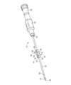
- FIG. 1 is a right side view of a needle assembly provided with a needle tip protector as a first embodiment of the present invention
- FIG. 2 is an enlarged view of the IV-IV cross section of FIG.
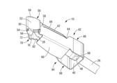
- FIG. 2 is an enlarged perspective view showing a needle tip protector that constitutes the needle assembly of FIG. 1
- 6 is a perspective view showing the needle tip protector shown in FIG. 5 at another angle
- FIG. 6 is a perspective view showing a state in which the needle tip protector of FIG. 5 is attached to the inner needle.
- 6 is a perspective view of a needle tip portion showing a needle tip protection state by the needle tip protector of FIG. 5;
- FIG. FIG. 14 is a perspective view showing the needle tip portion of FIG. 14 at another angle
- FIG. 14 is a vertical cross-sectional view of the tip portion of the needle shown in FIG. 14 and corresponds to the XVI-XVI cross section of FIG. 17; XVII-XVII sectional view of FIG.
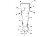
- FIG. 15 is an enlarged plan view showing the needle tip protector in the needle tip protection state shown in FIG. 14;
- FIG. 15 is a bottom view showing the needle tip protector in the needle tip protection state shown in FIG.
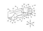
- FIG. 21 is a perspective view of a needle tip protector that constitutes the needle assembly of FIG. 20; 22 is a perspective view showing the needle tip protector of FIG. 21 at another angle;
- FIG. FIG. 20 is a cross-sectional view of the needle tip protector shown in FIG. 20, which corresponds to the XXIII-XXIII cross section of FIG. 24; XXIV-XXIV sectional view of FIG.
- FIG. 21 is a cross-sectional view of the needle tip portion showing the needle tip protection state by the needle tip protector of FIG. FIG.
- FIG. 25 is a cross-sectional view of a needle tip portion showing a state in which the needle tip is detached from the second needle tip cover portion in the needle tip protection state of FIG.
- FIG. 28 is a perspective view of a needle tip protector that constitutes the needle assembly of FIG. 27;
- FIG. 29 is a perspective view showing the needle tip protector of FIG. 28 from another angle;
- FIG. 28 is a plan view of the needle tip protector shown in FIG. 28 Front view of needle tip protector shown in FIG. Rear view of the needle tip protector shown in FIG. FIG.
- 35 is a cross-sectional view of the needle tip portion showing the needle tip protection state by the needle tip protector of FIG. 28, which corresponds to the XXXIV-XXXIV cross section of FIG. 35; XXXV-XXXV sectional view of FIG.
- FIG. 1 to 4 show a needle assembly 12 provided with a needle tip protector 10 as a first embodiment of the invention.
- the needle assembly 12 is configured by combining an outer needle unit 14 and an inner needle unit 16 .
- the front-back direction refers to the left-right direction in FIG. 1, which is the direction of the needle axis
- the up-down direction refers to the up-down direction in FIG. To tell.
- the left side in FIG. 1, which is on the needle tip 30 side, which will be described later, is the distal end
- the right side in FIG. 1 is the proximal end.
- the outer needle unit 14 has a structure in which an outer needle hub 20 is fixed to the base end portion of the outer needle 18 .
- the outer needle 18 is a tube-shaped member made of synthetic resin or the like, and the outer diameter of the tip portion decreases toward the tip.
- the proximal end portion of the outer needle 18 is inserted into the distal end portion of a cylindrical outer needle hub 20 , and the proximal end portion of the outer needle 18 and the distal end portion of the outer needle hub 20 are press-fitted by a caulking pin 22 . , is fixed to the outer needle hub 20 .
- the outer needle hub 20 is a generally cylindrical member made of hard synthetic resin, and has a luer taper that increases in diameter toward the base end on the inner peripheral surface.
- a syringe tip or connector (not shown) into the lumen of the outer needle hub 20
- an external circuit such as a syringe or an infusion line can be connected to the lumen of the outer needle hub 20.
- a threaded portion 23 protruding outward is formed at the base end portion of the outer needle hub 20, and the threaded portion 23 is screwed into a lock portion (not shown) to allow external circuits such as a syringe and an infusion line to be connected. can be prevented from coming out of the outer needle hub 20 unintentionally.
- a locking stepped portion 24 is formed on the inner peripheral surface of the outer needle hub 20 .
- the locking stepped portion 24 is a step provided so as to narrow the lumen of the outer needle hub 20 on the proximal side rather than the distal side, and the locking stepped portion 24 of this embodiment is enlarged in FIG. , it is constituted by a side wall surface on the base end side of a concave groove that opens in the inner peripheral surface of the outer needle hub 20 and extends annularly in the circumferential direction, and is provided continuously over the entire circumference.
- the inner needle unit 16 has a structure in which an inner needle hub 28 is attached to the base end portion of the inner needle 26 as a puncture needle.
- the inner needle 26 is a hollow needle made of medical metal such as stainless steel, and has a sharp tip 30 at its tip.
- the needle tip 30 is formed by having a blade surface 32 that widens at an angle to the tip of the inner needle 26 with respect to the needle axis.
- the proximal end portion of the inner needle 26 is inserted into the distal end portion of a cylindrical inner needle hub 28, and the inner needle 26 and the inner needle hub 28 are fixed by means of adhesion or the like.
- the inner needle hub 28 is a substantially cylindrical member made of hard synthetic resin.
- the distal end of the inner needle hub 28 is provided with a cylindrical connecting portion 34 that can be fitted into the proximal end opening of the outer needle hub 20 .
- a filter cap 36 is fitted to the proximal end opening of the inner needle hub 28 .
- the connecting portion 34 of the inner needle hub 28 is fitted into the base end opening portion of the outer needle hub 20, and the inner needle 26 is inserted through the outer needle 18 and the outer needle hub 20.
- the needle assembly 12 is constructed by combining them in a folded state.
- the outer needle unit 14 and the inner needle unit 16 apply a tensile force toward the proximal end side of the outer needle unit 14 to the inner needle unit 16, so that the connection portion 34 is fitted to the outer needle hub 20. released and separable from each other.
- a needle tip protector 10 is attached to the inner needle 26 .
- the needle tip protector 10 is made of a metal material such as medical stainless steel.
- the later-described parts constituting the needle tip protector 10 are integrally formed, and the needle tip protector 10 can be easily manufactured by, for example, pressing a metal base plate.
- the needle tip protector 10 has a first side plate portion 42 and a second side plate portion extending from both edges of a bottom portion 40 positioned on the needle base side of the inner needle 26 (on the side opposite to the needle tip 30). 44 has a structure extending toward the needle tip 30 side. 5 to 12, the needle tip protector 10 is shown in a state before actuation (before needle tip protection) for ease of viewing, but the needle tip protector 10 is shown after actuation (needle tip protection). 5 to 12 by attachment to the inner needle 26. As shown in FIGS.
- the bottom part 40 has a substantially rectangular flat plate shape and is provided with an insertion hole 46 penetrating in the plate thickness direction.
- a first side plate portion 42 and a second side plate portion 44 are integrally formed on a pair of opposing sides of the bottom portion 40 and extend to one side of the bottom portion 40 in the plate thickness direction.
- the first side plate portion 42 and the second side plate portion 44 of the present embodiment are arranged to face each other with the inner needle 26 interposed therebetween, and do not extend crosswise.
- the first side plate portion 42 has a substantially rectangular plate shape as a whole, and is longitudinal in the length direction (horizontal direction in FIG. 7), which is the extending direction from the bottom portion 40 .
- the first side plate portion 42 includes a first main body portion 48 extending from the bottom portion 40 and a first needle tip protection portion 50 located on the distal end side of the first main body portion 48 .
- the first side plate portion 42 preferably has a plate width dimension of 1 to 5 mm.
- the length direction is the direction in which the first and second side plate portions 42 and 44 extend from the bottom portion 40, and the vertical direction in FIG. 9 means the vertical direction in FIG.
- the first needle tip protection portion 50 includes a first tip protection piece 52 that protrudes to the tip side while being inclined toward the second side plate portion 44 side.
- a first return piece 54 that protrudes toward the second side plate portion 44 while being inclined toward the bottom portion 40 is provided on the front end side of the first tip protection piece 52 .
- a pair of side cover pieces 56 extending substantially perpendicular to the width direction and protruding in substantially the same direction as the first return pieces 54 are provided on both sides in the width direction of the tip portion of the first tip protection piece 52 . 56 is provided.
- the base end portion of the first tip protection piece 52 is provided with a first stepped portion 58 projecting outward toward the second side plate portion 44 , and the first stepped portion 58 extends toward the tip of the first body portion 48 . is integrally continuous with In other words, the base end of the first tip protection piece 52 is shifted from the tip of the first body portion 48 by the first stepped portion 58 to the side opposite to the second side plate portion 44 .
- a first notch 60 is formed in the tip end edge of the first return piece 54 protruding from the first tip protection piece 52 .
- the first notch 60 is provided in the center portion of the first return piece 54 in the width direction, and is wider than the thickness dimension (axial dimension) of the first return piece 54 .
- the dimension in the direction is increased, and the length is shorter than the width dimension of the first return piece 54 and extends in the width direction.
- the inner surface of the first notch 60 is a substantially arc-shaped curved surface having a smaller curvature than the outer peripheral surface of the inner needle 26, and the depth dimension of the first notch 60 increases toward the center in the width direction. It's becoming The inner surface of the first notch 60 has an arcuate shape that is less than half the circumference, and the length dimension of the first notch 60 in the width direction is larger than the diameter of the inner needle 26 .
- the first body portion 48 is provided with a first side cover piece 62 as a side cover piece. As shown in FIGS. 7 and 9, the first side cover piece 62 extends from one edge portion in the width direction of the first main body portion 48 toward the second side plate portion 44. It is provided at an intermediate position in the length direction of the portion 48 so as to be biased toward the distal end side.
- the first concave portion 64 is open at one end edge portion in the width direction of the first main body portion 48, and the width of the first main body portion 48 is narrowed at the portion where the first concave portion 64 is formed.
- the first concave portion 64 has a notch shape that penetrates the first main body portion 48 in the plate thickness direction, and is provided at an intermediate portion of the first main body portion 48 in the front-rear direction. It does not reach both ends in the front-rear direction of the first body portion 48 . Therefore, the first main body portion 48 is narrower than the first concave portion 64 at the portion where the first concave portion 64 is formed.
- the depth dimension in the vertical direction of the first recessed portion 64 decreases outward in the front-rear direction at both the front and rear end portions. In other words, the length dimension in the front-rear direction of the first concave portion 64 increases toward the side opening side. The depth dimension of the first concave portion 64 is maximum on both sides of the first side cover piece 62 in the front-rear direction.
- the first side cover piece 62 is provided so as to protrude inward in the left-right direction from the bottom of the first recessed portion 64 , and covers the widthwise outer end of the first main body portion 48 including the opening end of the first recessed portion 64 . is positioned on the inner side in the width direction.
- the first side cover piece 62 has a substantially constant protrusion height from the first side plate portion 42 at the base end portion near the bottom portion 40, and has a tip end portion near the first needle tip protection portion 50. The protrusion height is gradually reduced toward the tip.
- the first side cover piece 62 preferably has a length dimension of 1 to 5 mm and a maximum protrusion height dimension from the first body portion 48 of 1 to 3 mm.
- the first side cover piece 62 is arranged to reliably cover the side of the inner needle 26, and the protruding tip of the first side cover piece 62 is provided. and the second side plate portion 44 is prevented from malfunctioning.
- a first projecting piece 66 is provided on the first body portion 48 as a projecting piece. As shown in FIG. 8, the first protruding piece 66 extends from the other widthwise edge of the first body portion 48 toward the second side plate portion 44, and extends in the length direction of the first body portion 48. It is provided so as to deviate toward the distal end side at an intermediate position.
- the first protruding piece 66 is provided on the edge portion of the first main body portion 48 opposite to the first side cover piece 62 , and faces the first side cover piece 62 at a distance in the width direction. and distributed. In this embodiment, the first side cover piece 62 and the first protruding piece 66 extend substantially parallel to each other. As shown in FIG.
- the first protruding piece 66 has a length dimension (vertical dimension in FIG. 7) larger than that of the first side cover piece 62, and is It extends to both sides in the length direction.
- the protrusion height of the first projecting piece 66 from the first body portion 48 is substantially the same as that of the first side cover piece 62 .
- the first protruding piece 66 has a substantially constant protruding height at the proximal end portion in the length direction, and the protruding height at the distal end portion in the length direction increases toward the distal end. It is getting smaller towards
- the width direction of the first main body portion 48 is reduced. 9) is on the opposite side of the first side cover piece 62 in the width direction (first protruding piece 66 side).
- the central position of the bottom portion 40 substantially coincides with the central axis of the insertion hole 46, and substantially coincides with the needle axis of the inner needle 26 inserted through the insertion hole 46. Therefore, the two-dot chain line in FIG. , indicate the position of the needle shaft of the inner needle 26 in the width direction.
- the second side plate portion 44 has a substantially rectangular plate shape as a whole, and is longitudinal in the extending length direction from the bottom portion 40 (vertical direction in FIG. 7).
- the second side plate portion 44 includes a second main body portion 68 extending from the bottom portion 40 and a second needle tip protection portion 70 located on the distal end side of the second main body portion 68 .
- the second side plate portion 44 preferably has a plate width dimension of 1 to 5 mm.
- the second needle tip protection part 70 includes a second tip protection piece 72 that is inclined toward the first side plate part 42 toward the tip side, and that the tip of the second tip protection piece 72 is directed toward the bottom part 40 .
- a second return piece 74 is provided that protrudes toward the first side plate portion 42 while being inclined toward the side.
- the base end portion of the second tip protection piece 72 is provided with a second stepped portion 76 protruding outward toward the first side plate portion 42 , and the second stepped portion 76 extends from the second side plate portion 44 . It is integrally continuous with the tip of the two main body portions 68 .
- the base end of the second tip protection piece 72 is shifted from the tip of the second body portion 68 by the second stepped portion 76 to the side opposite to the first side plate portion 42 .
- Side cover pieces corresponding to the side cover pieces 56, 56 of the first needle tip protection portion 50 are not provided in the second needle tip protection portion 70, and the side of the second needle tip protection portion 70 is Open without being covered.
- the pair of side cover pieces 56 , 56 on both sides in the plate width direction are both provided on the first probe tip protection portion 50 .
- a second notch 78 is formed in the tip end edge of the second return piece 74 protruding from the second tip protection piece 72 .
- the second notch 78 is provided in the center portion of the second return piece 74 in the width direction, and is wider than the thickness dimension (axial dimension) of the second return piece 74 .
- the dimension in the direction is increased, and the length is shorter than the width dimension of the second return piece 74 and extends in the width direction.
- the inner surface of the second notch 78 is a substantially arc-shaped curved surface with a smaller curvature than the outer peripheral surface of the inner needle 26, and the depth dimension of the second notch 78 increases toward the center in the width direction. It's becoming The inner surface of the second notch 78 has an arc shape that is less than half the circumference, and the length dimension of the second notch 78 in the width direction is larger than the diameter of the inner needle 26 .
- the second body portion 68 is provided with a second side cover piece 80 as a side cover piece. As shown in FIGS. 8 and 10, the second side cover piece 80 extends from one edge portion in the width direction of the second body portion 68 toward the first side plate portion 42, and extends toward the first side plate portion 42. As shown in FIGS. It is provided at an intermediate position in the length direction of the portion 68 so as to be biased toward the distal end side.
- the second body portion 68 has an opening at one side end portion of the second body portion 68 , and the width of the second body portion 68 is narrowed at the second recessed portion 82 .
- the second concave portion 82 has a notch shape that penetrates the second main body portion 68 in the plate thickness direction, and is provided at an intermediate portion of the second main body portion 68 in the front-rear direction. It does not reach both ends of the second body portion 68 in the front-rear direction. Accordingly, the second main body portion 68 is narrower than the second concave portion 82 at the portion where the second concave portion 82 is formed.
- the second recessed portion 82 has a depth dimension in the up-down direction that decreases outward in the front-rear direction at both the front and rear end portions.
- the length dimension in the front-rear direction of the second concave portion 82 increases toward the side opening side.
- the depth dimension of the second concave portion 82 is maximum on both sides of the second side cover piece 80 in the front-rear direction.
- the second side cover piece 80 is provided so as to protrude inward in the left-right direction from the bottom of the second concave portion 82 , and extends from the widthwise outer end of the second body portion 68 including the opening end of the second concave portion 82 . is positioned on the inner side in the width direction.
- the second side cover piece 80 has a substantially constant protrusion height from the second side plate portion 44 at the base end portion near the bottom portion 40, and has a tip end portion near the second needle tip protection portion 70. The protrusion height is gradually reduced toward the tip.
- the second side cover piece 80 preferably has a length dimension of 1 to 5 mm and a maximum protrusion height dimension from the second body portion 68 of 1 to 3 mm.
- a second projecting piece 84 is provided on the second body portion 68 as a projecting piece. As shown in FIG. 7, the second protruding piece 84 extends from the other widthwise edge of the second body portion 68 toward the first side plate portion 42, and extends in the length direction of the second body portion 68. It is provided so as to deviate toward the distal end side at an intermediate position.
- the second protruding piece 84 is provided on the edge portion of the second main body portion 68 opposite to the second side cover piece 80 and faces the second side cover piece 80 in the width direction while being separated from each other. distributed. In this embodiment, the second side cover piece 80 and the second projecting piece 84 extend substantially parallel to each other. As shown in FIG.
- the second protruding piece 84 has a length dimension (vertical dimension in FIG. 8) larger than that of the second side cover piece 80. It extends to both sides in the length direction.
- the protrusion height of the second projecting piece 84 from the second body portion 68 is substantially the same as that of the second side cover piece 80 .
- the second projecting piece 84 has a substantially constant projecting height at the base end portion in the length direction, and the projecting height at the distal end portion in the length direction increases toward the tip. It is getting smaller towards
- the center position of the second side cover piece 80 and the second projecting piece 84 in the opposing direction (width direction) indicated by the dashed line in FIG. is shifted to the second projecting piece 84 side in the width direction with respect to the center position of .
- the center of the second main body portion 68 in the plate width direction (one-dot chain line in FIG. 10) is aligned with the bottom portion. 40 in the same direction (the two-dot chain line in FIG. 10), in the width direction, it is shifted to the side opposite to the second side cover piece 80 (the side of the second protruding piece 84).
- the center of the width direction of the portion of the first body portion 48 where the first side cover piece 62 and the first projecting piece 66 are formed (one-dot chain line in FIG. 9) and the second side of the second body portion 68
- the center in the plate width direction of the portion where the cover piece 80 and the second protruding piece 84 are formed (one-dot chain line in FIG. 10) is shifted to the side opposite to the side cover pieces 62 and 80 .
- the two-dot chain line in FIG. 10 also substantially coincides with the position of the needle shaft of the inner needle 26 in the width direction.
- the first side cover piece 62 and the second protruding piece 84 are provided at the edge portions on the same side in the width direction of the first side plate portion 42 and the second side plate portion 44, and the inner needle 26 before protecting the needle tip. They are overlapped with each other in the width direction in the attached state. As shown in FIG. 12 , the first side cover piece 62 is spaced inward in the width direction from the second projecting piece 84 . The first side cover piece 62 has a protruding height that does not reach the second side plate portion 44, and the second protruding piece 84 has a protruding height that does not reach the first side plate portion 42. The side cover piece 62 and the second projecting piece 84 partially overlap each other. In addition, as shown in FIG.
- the second protruding piece 84 extends to both sides of the first side cover piece 62 in the longitudinal direction.
- the longitudinal center position of the second protruding piece 84 is offset from the longitudinal center position of the first side cover piece 62 toward the opposite side (front end side) of the bottom portion 40 .
- the second side cover piece 80 and the first projecting piece 66 are provided at the edge portions on the same side in the width direction of the first side plate portion 42 and the second side plate portion 44. They overlap each other in the width direction when attached to the needle 26 .
- the second side cover piece 80 is spaced inward in the width direction from the first projecting piece 66 .
- the second side cover piece 80 has a protruding height that does not reach the first side plate portion 42
- the first protruding piece 66 has a protruding height that does not reach the second side plate portion 44.
- the side cover piece 80 and the first projecting piece 66 partially overlap each other.
- the first protruding piece 66 extends to both sides of the second side cover piece 80 in the longitudinal direction.
- the lengthwise center position of the first projecting piece 66 is biased toward the bottom portion 40 with respect to the lengthwise center position of the second side cover piece 80 .
- the first side cover piece 62 and the second side cover piece 80 are provided on opposite sides in the width direction, and are spaced apart from each other in the width direction.
- the first protruding piece 66 and the second protruding piece 84 are provided on opposite sides in the width direction, and face each other while being separated from each other in the width direction. 80 on both sides in the width direction.
- the first side cover piece 62 is longer than the second side cover piece 80, and the tip position is substantially the same as that of the second side cover piece 80.
- the base end position is closer to the bottom part 40 than the second side cover piece 80 is.
- the first protruding piece 66 and the second protruding piece 84 have substantially the same length dimension, and the first protruding piece 66 is arranged to be shifted toward the bottom portion 40 from the second protruding piece 84. .
- the first and second side cover pieces 62 and 80 and the first and second protruding pieces 66 and 84 are separated from the bottom portion 40 in the longitudinal direction toward the tip side. Between the first and second side cover pieces 62 and 80 and the first and second projecting pieces 66 and 84 and the bottom portion 40, between the facing surfaces of the first and second side plate portions 42 and 44, Molding spaces 86 are formed that penetrate in the width direction and are open on both sides in the width direction.
- the first and second side cover pieces 62, 80 and the first and second protruding pieces 66, 84 are 2.5 mm from the base end side (the tip surface of the bottom portion 40) of the first and second side plate portions 42, 44.
- the longitudinal dimension of the molding space 86 is preferably 2.5 mm or more, more preferably 3.5 mm or more.
- the lengthwise dimension of the molding space 86 is preferably 7 mm or less, more preferably 5 mm or less.
- the needle tip protector 10 is formed by, for example, pressing (progressive pressing) a blank metal plate that has been punched into a predetermined shape and bending it. It is possible to work while pressing. That is, during press working, the portion corresponding to the bottom portion 40 is sandwiched in the plate thickness direction by a support jig (not shown) that supports one surface and a pressing jig (not shown) that supports the other surface.
- the pressing jig has a shape that allows it to be inserted into the molding space 86, and is superimposed on the rising sides of the first and second side plate portions 42 and 44 with respect to the bottom portion 40. Since the bottom portion 40 can be held in a sandwiched state up to , molding of the needle tip protector 10 is facilitated.
- the pressing jig also functions as a mold for bending the first and second side plate portions 42 and 44 to form the bottom portion 40 .
- the raw metal plate processed into the needle tip protector 10 by the progressive press is made of, for example, stainless steel or titanium for medical use, and is preferably a plate material having a thickness of 0.1 to 0.3 mm. .
- the needle tip protector 10 is provided with a sufficiently small sliding resistance against the inner needle 26 and with deformation rigidity capable of stably maintaining the needle tip protection form. In addition, damage during press working is less likely to be a problem.
- the needle tip protector 10 may have a substantially constant thickness as a whole, or may have a partially thick portion and/or a thin portion.
- the needle tip protector 10 constructed as described above is attached to the inner needle 26 as shown in FIG. That is, the inner needle 26 is inserted through the insertion hole 46 formed in the bottom portion 40 of the needle tip protector 10 , and the first return piece 54 of the first needle tip protection portion 50 and the second needle tip protection portion 70 . It is inserted between it and the second return piece 74 . As a result, the inner needle 26 is arranged to pass through the gap between the first side plate portion 42 and the second side plate portion 44 of the needle tip protector 10 , so that the needle tip protector 10 is externally attached to the inner needle 26 . be worn.
- the inner needle 26 is positioned between the opposing first side cover piece 62 and the second side cover piece 80 of the needle tip protector 10, and is partially surrounded by the first and second side plates in the needle axial direction. It is surrounded by the portions 42,44 and the first and second side cover pieces 62,80.
- the needle tip protector 10 is arranged at a position away from the inner needle hub 28 toward the needle tip 30 for ease of viewing, but as shown in FIGS.
- the needle tip protector 10 can be positioned so that the bottom 40 contacts or is close to the tip of the inner needle hub 28 .
- the inner needle 26 When the needle tip protector 10 is attached to the inner needle 26, the inner needle 26 has a first notch 60 of the first return piece 54 and a second notch 60 of the second return piece 74, as shown in FIGS.
- the inner surfaces of the first and second notches 60 and 78 are in contact with the outer peripheral surface of the inner needle 26 .
- the first and second return pieces 54 and 74 come into contact with the inner needle 26 at the first and second notches 60 and 78, the first and second side plate portions 42 and 44 are elastically deformed.
- the first and second return pieces 54 and 74 are pressed against the inner needle 26 by the elastic restoring force of the second side plate portions 42 and 44 .
- the inner surfaces of the first and second cutouts 60 and 78 have a smaller curvature than the outer peripheral surface of the inner needle 26, the inner needle 26 and the first and second cutouts 60 and 78 at the first and second cutouts 60 and 78 have a smaller curvature.
- the contact area with the second return pieces 54 and 74 is made small.
- the needle shaft of the inner needle 26 is positioned so that the needle shaft of the first side plate portion 42 of the needle tip protector 10 is positioned relative to the center of the plate width direction of the first side plate portion 42 of the needle tip protector 10 . It is deviated to the approach side to the first side cover piece 62 in the plate width direction. Further, the needle shaft of the inner needle 26 is closer to the second side cover piece 80 in the plate width direction of the second side plate portion 44 than the center of the second side plate portion 44 in the needle tip protector 10 in the plate width direction. shifted to the side.
- first and second side plate portions 42 and 44 which are displaced in the plate width direction with respect to the needle axis of the inner needle 26
- the first and second side plate portions 42 and 44 are provided at the width direction edge portions on the approach side to the inner needle 26.
- a second side cover piece 62, 80 is provided.
- the needle tip protector 10 is accommodated in the lumen of the outer needle hub 20, as shown in FIGS.
- the tip portion of the needle tip protector 10 is tapered because the first and second tip protection pieces 52 and 72 are inclined toward the tip and approach each other.
- Both ends in the width direction of the first and second stepped portions 58 and 76 of the needle tip protector 10 are axially locked to the locking stepped portion 24 provided on the inner peripheral surface of the outer needle hub 20 . and its proximal movement relative to the outer needle hub 20 is restricted.
- the outermost rectangular portions of the bottom portion 40 and the needle tip cover portions 50 and 70 are can be arranged in close proximity to or in contact with the inner peripheral surface of the outer needle hub 20 .
- the connecting portion 34 of the inner needle hub 28 inserted into the outer needle hub 20 is partially extended in the circumferential direction. It may be made to protrude to the side (see FIGS. 3 and 13), and the protruding portion may enter the outer periphery of the bottom portion 40 of the needle tip protector 10 .
- the inner needle 26 and the outer needle 18 are punctured into a patient's blood vessel or the like.
- blood flows into the lumen of the inner needle hub 28 through the lumen of the inner needle 26.
- the filter 38 of the filter cap 36 attached to the inner needle hub 28 can prevent the blood that has flowed into the lumen of the inner needle hub 28 from leaking out from the opening on the proximal end side.
- the inner needle 26 After puncturing the blood vessel with the inner needle 26 and the outer needle 18, the inner needle 26 is pulled from the outer needle 18 to the proximal side by pulling the inner needle unit 16 toward the proximal side while holding the outer needle unit 14 at the puncturing position. can be pulled out. At this time, the connection between the inner needle hub 28 and the outer needle hub 20 is released, and the entire inner needle unit 16 is separated from the outer needle unit 14 .
- the end edges of the first and second barbed pieces 54 and 74 of the needle tip protector 10 slide against the outer peripheral surface of the inner needle 26 . Since the first and second barbed pieces 54 and 74 are slanted toward the inner needle 26 toward the proximal end side, when the inner needle 26 is pulled out, the end edges of the first and second barbed pieces 54 and 74 is less likely to get caught on minute irregularities on the outer peripheral surface of the inner needle 26, sliding resistance is suppressed, and smooth withdrawal of the inner needle 26 to the proximal end side is realized.
- the inner needle 26 When the inner needle 26 is pulled out to the proximal end side, the inner needle 26 is axially pulled by the first and second notches 60 and 78 provided in the first and second return pieces 54 and 74 of the needle tip protector 10. Being guided, smooth withdrawal of the inner needle 26 to the proximal end side is assisted.
- the first and second notches 60 and 78 have a length dimension in the width direction (horizontal direction in FIG. 4) that is larger than the diameter of the inner needle 26, so that the inner needle 26 can move in the width direction. Even if it moves a little, it is difficult to come off the first and second notches 60 and 78, and the function of guiding the inner needle 26 by the first and second notches 60 and 78 is effectively exhibited.
- first and second notches 60 and 78 are formed extending in the width direction of the first and second return pieces 54 and 74, the inner needle 26 and the first and second return pieces 54 and 74 are in contact with each other in a narrow range in the direction of the needle axis. For example, the sliding resistance due to the surface roughness of the contact portion is reduced, and the operation of pulling out the inner needle 26 is facilitated.
- the member thickness dimension of the first and second return pieces 54 and 74 is sufficiently smaller than the outer diameter of the inner needle 26. Since the tip surfaces of the first and second return pieces 54 and 74 are substantially perpendicular to the plate surface, the inner needle 26 and the first and second return pieces 54 and 74 in the attached state shown in FIG. 74 are in approximate line contact or point contact.
- the curvature of the inner surfaces of the first and second notches 60 and 78 is smaller than the curvature of the outer peripheral surface of the inner needle 26, so that the first and second return pieces 54 and 74 and the inner needle 26 are curved in the circumferential direction.
- the narrower contact range at 1 also reduces the resistance at the time of withdrawal.
- the inner needle 26 and the first and second return pieces 54, 74 are in contact with each other in a substantially point-contact state at one point, and the sliding resistance due to contact is sufficiently small. It is
- the outer needle unit 14 separated from the inner needle unit 16 is indwelled as an indwelling needle in a state of puncturing the blood vessel, and an external circuit (not shown) is connected to the proximal end side of the outer needle hub 20 to access the blood vessel. It functions as a port, and is used, for example, as an injection port for infusion or medicine, a blood removal port for artificial dialysis, or a blood return port.
- the needle tip 30 of the inner needle 26 is moved toward the needle tip 30 side with respect to the inner needle 26 by the needle tip protector 10, as shown in FIGS. covered. That is, when the inner needle 26 moves to the proximal side with respect to the needle tip protector 10 whose movement to the proximal side is restricted by the outer needle hub 20, the outer peripheral surface of the inner needle 26 and the first and second return pieces 54 , 74 are released, and the first and second side plate portions 42, 44 elastically restore their shape.
- the first and second side plate portions 42 and 44 are inclined toward the distal end so as to approach each other, and both the first needle tip protection portion 50 and the second needle tip protection portion 70 are positioned at the tip end of the inner needle 26 .
- a needle tip covering portion covering the needle tip 30 is constituted by the first and second needle tip protection portions 50 and 70 .
- the needle tip 30 of the inner needle 26 is not exposed to the distal side, and the movement of the inner needle 26 to the distal side is restricted by contact with the first and second needle tip protection portions 50 and 70. Therefore, the risk of erroneous puncture due to exposure of the inner needle 26 is avoided.
- the first and second return pieces 54 and 74 of the first and second needle tip protection portions 50 and 70 overlap each other on the tip end side of the needle tip 30.
- a high degree of safety is ensured by covering the distal end side of the inner needle 26 with the first and second needle tip protection portions 50 and 70 in a doubly manner.
- a pair of side cover pieces 56, 56 provided on the first needle tip protection portion 50 cover the needle tip 30 so that it is difficult to see from the outside. Further, even if the needle tip 30 moves to the distal end side, the pair of side cover pieces 56, 56 allows the needle tip 30 to move the first and second needle tip protection portions 50, 70 in the width direction (see FIG. 17). vertical direction) and is prevented from being exposed to the outside.
- the pair of side cover pieces 56, 56 are located on the sides of the second tip protection piece 72 and the second return piece 74 in the needle tip protection state.
- relative displacement of the first probe tip protection portion 50 and the second probe tip protection portion 70 to the side is It is limited by contact with the return piece 74 . Therefore, re-exposure of the needle tip 30 due to unintended relative lateral displacement of the first and second needle tip protection portions 50 and 70 is prevented.
- the first and second main body portions 48 and 68 of the first and second side plate portions 42 and 44 are approaching each other toward the distal end.
- the tip portions of the first and second body portions 48, 68 are close to the inner needle 26 in the left-right direction.
- the amount of displacement (deflection) of the inner needle 26 in the facing direction (horizontal direction) of the first and second body portions 48 and 68 is limited, and exposure of the needle tip 30 due to displacement in the lateral direction is prevented. be done.
- both the first and second side cover pieces 62 and 80 can be arranged sufficiently close to the thin inner needle 26 for medical use, for example, about 16 to 24 G, and the inner needle 26 can effectively limit the displacement of the vertical direction.
- a thin needle such as 24G, for example, can be obtained.
- both the first and second side cover pieces 62, 80 should be sufficiently close to the inner needle 26 while ensuring the member strength of the needle tip protector 10. can be distributed.
- the first side cover piece 62 is provided so as to protrude inward in the vertical direction from the first recessed portion 64 of the first side plate portion 42, and the second side cover piece 80 is provided on the second side plate portion 42.
- the second concave portion 82 of the portion 44 is provided to protrude inward in the vertical direction. ing.
- the first side plate portion 42 is wide on both sides of the first recessed portion 64 in the front-rear direction, and deformation rigidity is ensured. Further, the first side plate portion 42 is integrally provided with the first side cover piece 62 protruding inward at the narrow first concave portion 64 forming portion. Due to the reinforcing action of the cover piece 62, deformation rigidity is ensured. In the second side plate portion 44, similarly to the first side plate portion 42, deformation rigidity is ensured in the portion where the second recessed portion 82 is formed and both front and rear sides thereof.
- the tips of the first and second side cover pieces 62 and 80 protruding from the first and second side plate portions 42 and 44 are inclined in consideration of the needle tip protection state. It does not interfere with the first and second side plate portions 42 and 44 in the needle tip protection state in which the second side plate portions 42 and 44 are inclined. Therefore, the deformation (restoration of shape) of the first and second side plate portions 42 and 44 occurs reliably without being hindered by the first and second side cover pieces 62 and 80, so that the needle tip protector 10 can be used as intended. stably shifts to the needle tip protection mode.
- the first side plate portion 42 protrudes outward in the width direction beyond the second side cover piece 80, the dimension in the width direction is ensured, and strength such as deformation rigidity is ensured. If the first side plate portion 42 protrudes outward in the width direction from the second side cover piece 80 in this manner, the state of protection of the needle tip 30 by the needle tip protector 10 is reduced when the protrusion is pushed by hand. is likely to be released. Therefore, by providing the first projecting piece 66 on the projecting portion, it becomes difficult to push the projecting portion, and the needle tip protection state of the needle tip protector 10 is stably maintained. As shown in FIG.
- the first protruding piece 66 reaches a position covering the side of the second side plate portion 44 in the needle tip protection state, and even if the first protruding piece 66 is pressed with a finger, Since it is difficult for a finger to be caught on the second side plate portion 44 and pushed in by a large amount, it is difficult to release the needle tip protection state.
- the second projecting piece 84 provided on the second side plate portion 44 is pushed at the portion projecting outward in the width direction from the first side cover piece 62 of the second side plate portion 44 .
- the second projecting piece 84 is provided with a projecting height that does not reach the first side plate portion 42 slightly, but the projecting tip is close to the first side plate portion 42. Therefore, as with the first protruding piece 66, fingers and the like are caught on the first side plate portion 42, making it difficult to be pushed in. As shown in FIG.
- the needle tip protector 10 which protects the needle tip 30 of the inner needle 26 while being accommodated in the outer needle hub 20, is separated from the outer needle hub 20 as the inner needle 26 is pulled out to the proximal end side. Withdraw proximally. That is, in the needle tip protector 10 in the needle tip protection state, the first and second side plate portions 42 and 44 are deformed so as to approach each other toward the distal end. and the locking stepped portion 24 of the outer needle hub 20 are released in the axial direction, and the needle tip protector 10 is allowed to move to the proximal side with respect to the outer needle hub 20 .
- a large-diameter portion 88 is provided near the tip of the inner needle 26.
- the large-diameter portion 88 has a partially enlarged outer diameter.
- the outer diameter dimension is larger than the inner diameter dimension of the insertion hole 46 formed in the bottom portion 40 of the needle tip protector 10 .
- the needle tip protector 10 protects the needle tip 30 of the inner needle 26 and separates from the outer needle hub 20 that is indwelled while puncturing the blood vessel. In this way, when the inner needle unit 16 is separated from the outer needle unit 14, the needle tip 30 of the inner needle 26 is covered with the needle tip protector 10. Therefore, when handling the separated inner needle unit 16, In addition, accidental contact with the needle tip 30 of the inner needle 26 can be prevented, thereby ensuring safety.
- FIG. 20 shows a needle assembly 92 provided with a needle tip protector 90 as a second embodiment of the invention.
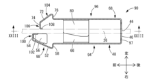
- the needle tip protector 90 is shown in FIGS. 21 to 24, and includes a first side plate portion 94 and a second side plate portion 96 extending from the bottom portion 40 toward the needle tip 30 (left side in FIG. 23). .
- members and parts that are substantially the same as those of the first embodiment are denoted by the same reference numerals in the drawings, and description thereof is omitted.
- the bottom portion 40 of the present embodiment is provided with a thin portion 97 as a stress transmission suppressing portion extending in a substantially square annular shape so as to surround the insertion hole 46 .
- the bottom portion 40 has a groove-like recessed shape on both front and back surfaces of the thin portion 97 .
- an external force acting from the outer peripheral side of the thin portion 97 is applied to the inner peripheral side. It is becoming difficult to transmit to This prevents the deformation of the inner peripheral portion of the bottom portion 40 and the accompanying deformation of the insertion hole 46 due to the action of an external force.
- the thin portion 97 is formed, for example, by coining similar to the thin portion 110 described later.
- the diameter of the insertion hole 46 of the bottom portion 40 is set according to the outer diameter of the inner needle 26, and in the present embodiment, the diameter is set smaller corresponding to the inner needle 26 thinner than in the first embodiment.
- the first side plate portion 94 has the same overall structure as the first side plate portion 42 of the first embodiment.
- the first side plate portion 94 has a structure in which a first needle tip protection portion 98 as a needle tip covering portion is integrally formed on the distal end side of the first body portion 48 .
- the first needle tip protection portion 98 includes a first needle tip cover portion 100 extending from the projecting tip of the first stepped portion 58 .
- the first needle tip cover portion 100 is composed of a first tip protection piece 52 provided continuously with the first stepped portion 58 and a first return piece 54 projecting from the tip of the first tip protection piece 52 . ing.
- the angle formed between the first tip protection pieces 52 is larger than in the first embodiment, and is an obtuse angle larger than 90°.
- a first needle tip stopper 102 is provided at the projecting tip of the first return piece 54 .
- the first needle tip restraining portion 102 has a rectangular plate shape and protrudes from the first return piece 54 toward the right side in FIG. 24, which is the needle base side.
- the first needle point restraining portion 102 is formed by bending, and is provided integrally and continuously with the first return piece 54 .
- Side cover pieces 56 , 56 extending from the first tip protection piece 52 are provided on the sides of the first needle tip protection portion 98 .
- the side cover piece 56 of the present embodiment is provided with a length reaching the first needle point restraining portion 102, and has a width dimension in the left-right direction larger than that of the first embodiment. Since the side covering piece 56 is wide enough to reach the first needle point restraining portion 102, the needle point 30 is less likely to be exposed to the side.
- the second side plate portion 96 has the same overall structure as the second side plate portion 44 of the first embodiment.
- the second side plate portion 96 has a structure in which a second needle tip protection portion 104 as a needle tip covering portion is integrally formed on the distal end side of the second body portion 68 .
- the second needle tip protection portion 104 includes a second needle tip cover portion 106 extending from the projecting tip of the second stepped portion 76 .
- the second needle tip cover portion 106 is composed of a second tip protection piece 72 provided continuously with the second stepped portion 76 and a second return piece 74 protruding from the tip of the second tip protection piece 72 . ing.
- the angle formed between the second tip protection pieces 72 of the second return pieces 74 of this embodiment is larger than that of the first embodiment, and is an obtuse angle larger than 90°.
- a second needle tip stopper 108 is provided at the projecting tip of the second return piece 74 .
- the second needle tip restraining portion 108 has a rectangular plate shape and protrudes from the second return piece 74 toward the right side in FIG. 24, which is the needle base side.
- the second needle point restraining portion 108 is formed by bending, and is provided integrally and continuously with the second return piece 74 .
- the protruding tip (end on the needle base side) of the first needle tip blocking portion 102 is closer to the tip side than the second needle tip protection portion 104 .
- the length dimension of the first needle tip restraining portion 102 is longer than the length dimension of the second needle tip restraining portion 108 . It is desirable that the axial distance between the first tip stop portion 102 and the second tip protection portion 104 is smaller than the length dimension of the first tip stop portion 102 .
- the first main body portion 48 of the first side plate portion 94 and the second main body portion 68 of the second side plate portion 96 each include a thin portion 110 linearly extending in the front-rear direction.
- the thin portion 110 is formed by coining (light forging by pressing a mold), and the thin portion 110 improves the deformation rigidity of the first and second main body portions 48 and 68, thereby forming a needle tip 30 which will be described later. Unintended opening of the first and second side plate portions 94 and 96 is prevented in the protection state of (2).
- the needle tip protector 90 is attached to the inner needle 26 as shown in FIG.
- the inner needle 26 is inserted between the first side plate portion 94 and the second side plate portion 96, and the first and second return pieces 54, 74 and the first and second needle tip restraining portions 102, 108 are connected to the inner needle. 26 is in contact with the outer peripheral surface.
- the first side plate portion 94 and the second side plate portion 96 are displaced in the left-right direction to the side away from each other, and the first side plate portion 94 and the second side plate portion 96 are moved toward each other. is acting.
- the first and second side cover pieces 62, 80 of this embodiment are arranged at a position closer to the inner needle 26 with a shorter distance between the facing surfaces than in the first embodiment. , and the allowable amount of movement of the inner needle 26 in the vertical direction is made smaller.
- the needle tip 30 of the inner needle 26 is covered and protected by the needle tip protector 90 moved to the needle tip 30 side, as shown in FIG. That is, the contact of the first and second return pieces 54 and 74 and the first and second needle tip restraining portions 102 and 108 to the inner needle 26 is released, so that the first and second needle tip protection portions 98 are released. , 104 are displaced so as to approach each other, and the first and second needle tip cover portions 100 and 106 move to the extension of the inner needle 26 on the needle tip 30 side.
- the distal end side of the needle tip 30 is covered with the first and second needle tip cover portions 100 and 106 , and the needle tip 30 of the inner needle 26 is put into a needle tip protection state by the needle tip protector 90 . Since the first needle tip restraining portion 102 is positioned on the distal end side without being caught by the second needle tip cover portion 106, it does not interfere with the approaching displacement of the first and second side plate portions 94 and 96. FIG.
- the projecting tip of the second side cover piece 80 is pressed against the first body portion 48 of the first side plate portion 94 .
- the projecting tip of the first side cover piece 62 is pressed against the second body portion 68 of the second side plate portion 96 .
- the biasing force of the first side plate portion 94 and the second side plate portion 96 in the mutually approaching direction is set to be larger, and the first side plate portion 94 and the second side plate portion 96 are moved in the mutually separating direction by the action of the external force. Displacement is less likely to occur.
- the connecting portion between the second return piece 74 and the second needle tip restraining portion 108 is pressed against the first tip protection piece 52 .
- the relative approaching displacement amount of the first and second needle tip protection portions 98 and 104 is defined. is ensured, it is difficult for the inner needle 26 to push open the first and second needle tip protection portions 98 and 104 .
- the side cover pieces 56, 56 extend further to the proximal side than the second needle tip cover portion 106.
- the needle tip 30 covered with the second needle tip cover portion 106 is positioned between the facing surfaces of the side cover pieces 56, 56, and is prevented from being exposed to the outside.
- the side cover pieces 56 and 56 are provided so as to cover the connecting portion between the second barbed piece 74 and the second needle tip restraining portion 108 , the needle tip 30 can move along the second barbed piece 74 . Even if the needle tip 30 moves until it abuts against the second needle tip restraining portion 108, the needle tip 30 is kept covered with the side cover pieces 56, 56 without being exposed to the side.
- the inner needle 26 moves relative to the needle tip protector 90, so that the needle tip 30 becomes the second needle tip cover as shown in FIG.
- the first needle tip cover portion 100 may come off from the portion 106 and be abutted against the first needle tip cover portion 100 .
- the first needle point stopping portion 102 is provided at the protruding tip portion of the first return piece 54, and the needle point 30 moved along the first return piece 54 moves toward the first needle point stopping portion.
- the needle tip 30 is prevented from coming off toward the protruding distal end side of the first return piece 54 .
- the needle tip 30 is kept in a protected state covered with the first needle tip cover portion 100, and erroneous puncture can be prevented.
- the second needle tip restraining portion 108 is provided at the protruding distal end portion of the second barbed piece 74 , and the needle tip 30 is prevented from moving from the second needle tip cover portion 106 to the protruding tip portion of the second barbed piece 74 . It becomes difficult to come off to the side. Therefore, even if the needle tip 30 of the inner needle 26 moves laterally with respect to the needle tip protector 90, the protection state of the needle tip 30 is maintained.
- the projection dimension of the second needle tip restraining portion 108 is smaller than the projection dimension of the first needle tip restraining portion 102 .
- the inner needle 26 is The contact angle at the contact portion is different from that of the first embodiment.
- the contact portion with the inner needle 26 is the distal end surface of the return pieces 54 and 74 approaching the inner needle 26 from an oblique direction.
- the needle tip restraining portions 102, 108 provided at the distal ends of the needle tip covering portions 98, 104 extend substantially parallel to the inner needle 26, and each surface of the needle tip restraining portions 102, 108 extends. is a contact portion with the inner needle 26 .
- the needle tip covering portion Although the return pieces 54 and 74 located at the most extreme ends of 50 and 70 are inclined toward the needle hub side, the exposure movement direction of the needle tip (the left direction in FIG. 16), it is not an effective return portion, but in the present embodiment, the needle tip restraining portions 102, 108 positioned at the most extreme ends of the needle tip covering portions 98, 104 protrudes in the direction opposite to the exposure movement direction of the needle tip (the left direction in FIG. 25 for the needle tip cover portion 98, and the right direction in FIG. 25 for the needle tip cover portion 104) and serves as an effective return portion.
- FIG. 27 shows part of a needle assembly 122 with a needle tip protector 120 as a third embodiment of the invention.
- the needle tip protector 120 has a bottom portion 124 located on the needle base side of the inner needle 26 (left side in FIG. 30) and a needle tip 30 side from the bottom portion 124 (in FIG. 30, It has a first side plate portion 94 and a second side plate portion 96 extending to the right side).
- the needle tip protector 120 of this embodiment when housed in an outer needle hub 138 (described later) shown in FIG. is housed in a rotated orientation. Therefore, in the following description, the vertical direction of the needle tip protector 120 corresponds to the horizontal direction of the needle tip protector 90, and the horizontal direction of the needle tip protector 120 corresponds to the vertical direction of the needle tip protector 90 of the second embodiment. do.
- the bottom portion 124 has a substantially rectangular flat plate shape as a whole, similar to the bottom portion 40 of the second embodiment.
- a portion 96 is integrally formed.
- the bottom portion 124 is formed with an insertion hole 46 penetrating through the central portion in the plate thickness direction.
- the bottom portion 124 is formed with protrusions 126 that protrude leftward or rightward from opposite side portions on both left and right sides.
- Two protrusions 126 are formed at positions separated from each other in the vertical direction on the opposite left and right sides of the bottom portion 124, and a total of four protrusions 126 are formed on both the left and right sides.
- the projections 126 need only be provided on the opposite left and right sides, and the number and arrangement of the protrusions 126 on each opposite left and right sides are not particularly limited.
- the needle tip protector 120 is a press-formed product, and when it is manufactured by pressing a metal base plate, the parts other than the four projections 126, 126, 126, 126 are first cut off from the metal base plate. . Separation (press cutting) from the base metal plate at positions outside the projections 126 is cutting from the plate-shaped base metal plate before stress such as bending is applied. High-precision cutting is possible without the occurrence of Next, each part of the needle tip protector 120 is formed by bending while maintaining continuity with the metal base plate at each convex part 126 . After that, the needle tip protector 120 is manufactured by cutting each projection 126 .
- the cut part of the convex part 126 is more likely to have burrs during cutting than the other cut parts that are cut before the bending process. tends to be low.
- the portion where burrs are generated and the portion where processing accuracy is low when cutting from the metal base plate is limited to the convex portion 126, and burrs are prevented and The improvement of processing precision is achieved.
- the portion with low processing accuracy is limited to the convex portion 126, by performing post-processing such as chamfering and polishing on the convex portion 126 as necessary, the entire cut portion can be processed while reducing the time and effort of post-processing. It is also possible to achieve high dimensional and shape accuracy over the entire length.
- the bottom portion 124 is curved toward the center of the vertical direction in a state where the portions other than the convex portions 126 are separated from the base metal plate, and the first, It is desirable to form the second side plate portions 94, 96 and the like by press bending. According to this, by separating each convex portion 126 from the metal base plate and canceling the bending deformation of the bottom portion 124, the bending angle of the first and second side plate portions 94 and 96 with respect to the metal base plate is not increased, and the first 1.
- the inclination angle of the second side plate portions 94 and 96 with respect to the bottom portion 124 can be set smaller than 90°.
- the shape of the needle tip protector 120 in the needle tip protection state described later can be easily realized.
- the bottom portion 124 since the convex portions 126 are formed at both ends in the left-right direction, the bottom portion 124 can be easily bent in an arc shape between the convex portions 126, 126 on both the left and right sides. Note that even if the bottom portion 124 is slightly curved as a result of being press-bent while being curved into an arc as described above, the bottom portion 124 can be regarded as substantially having a flat plate shape. Also, the bottom portion 124 may have a plate shape that is positively curved by bending or the like.
- a plate of the first side plate portion 94 is provided at the continuous portion between the first tip protection piece 52, which is the base end portion of the first needle tip protection portion 98, and the first stepped portion 58.
- a first relief portion 128 is formed as a relief portion at both end portions in the left-right direction, which is the width direction.
- the first relief portion 128 has a notch shape (in this embodiment, a curved concave notch shape) that opens outward in the left-right direction, and extends outward in the left-right direction. It has an expanded shape with a larger width dimension.
- the left and right end portions of the continuous portion with the shaped portion 58 have curved outlines compared to the case where there is no first relief portion 128, which is virtually indicated by the two-dot chain line, in a projection view in the direction of the needle axis.
- the continuous portion between the first tip protection piece 52 and the first stepped portion 58 in the first needle tip protection portion 98 is constricted and narrowed in the left-right direction.
- the needle tip protector 120 makes it difficult to scrape.
- the needle shaft is Since the outer needle hub 138 is chamfered when viewed from the direction, a wide contact surface can be ensured, and the inner peripheral surface of the outer needle hub 138 is less likely to be scratched or otherwise damaged.
- a second relief portion 130 as a relief portion is provided at both ends in the left-right direction.
- the base end portion of the second needle tip protection portion 104 is narrowed in a constriction shape by forming a notch-like second relief portion 130 .
- the first tip protection piece 52 provided with the first relief portion 128 and the first stepped portion 76 are connected.
- the same effect as that of the continuous portion with the portion 58 is exhibited.
- the first relief portion 128 and the second relief portion 130 may have substantially the same shape and size, or may have different shapes and sizes.
- the provided second relief portion 130 can be made smaller than the first relief portion 128 provided on the elongated first side plate portion 94 side.
- the second needle tip protection portion 104 of the second side plate portion 96 has right and left sides of the second needle tip protection portion 104 in the same manner as the side cover pieces 56 of the first side plate portion 94 .
- a side cover piece 132 is provided to cover the sides.
- the side cover piece 132 extends from the second return piece 74 of the second probe tip protection portion 104, as shown in FIGS.
- the length of the second needle tip protection portion 104 of the present embodiment is shorter than that of the second embodiment, and the length of the second return piece 74 is longer.
- a first restricting protrusion 134 as a restricting protrusion is formed on a first projecting piece 66 as a side restricting piece extending from the first side plate portion 94 to a space between the first side plate portion 94 and the second side plate portion 96 facing each other. It is As shown in FIGS. 28 to 31, the first restricting protrusion 134 protrudes inward in the left-right direction from the front side of the first protruding piece 66 toward the inner needle 26 side.
- the first restricting protrusion 134 of the present embodiment is formed integrally with the front end portion of the first projecting piece 66 by bending the front end portion of the first projecting piece 66 inward in the left-right direction and extending it. ing.
- the first restricting protrusion 134 has a projecting tip on the inner side in the left-right direction, which is positioned close to the outer peripheral surface of the inner needle 26 with a distance in the left-right direction.
- a second protruding piece 84 as a side regulating piece extending from the second side plate portion 96 to a space between the first side plate portion 94 and the second side plate portion 96 facing each other is provided as a regulating protrusion projecting toward the inner needle 26 side. is formed.
- the second restricting protrusion 136 differs from the first restricting protrusion 134 in that it is formed integrally with the front end of the second projecting piece 84 and projects in the left-right opposite direction.
- the first restricting protrusion 134 and the second restricting protrusion 136 are positioned apart from each other in the left-right direction in the state before the needle tip protection operation of the needle tip protector 120 shown in FIGS. 28 to 33 .
- the first and second restricting projections 134 and 136 are preferably integrally formed by bending as in the present embodiment, but for example, the tip portions of the first and second projecting pieces 66 and 84 are thick. It may be provided by partially thickening it by bulging or the like, or it may be attached as a separate part to the tip portions of the first and second protruding pieces 66 and 84 . Also, considering the position regulating effect due to contact with the inner needle 26, only one of the first and second regulating protrusions (134, 136) may be provided, or each protruding piece may be provided. 84, and furthermore, the specific formation position and shape of the side regulating piece extending between the opposed first and second side plate portions 94 and 96 and provided with the protruding piece 84 are as follows. Not limited.
- the needle tip protector 120 is accommodated in the inner periphery of the outer needle hub 138 and attached to the inner needle 26 in an externally inserted state.
- the needle tip protector 120 is such that the inner needle 26 is inserted between the first and second needle tip protection parts 98 and 104 so that the first and second side plate parts 94 and 96 are They are separated in the facing direction, and the first and second needle tip protection portions 98 and 104 are pressed against the inner needle 26 by the elasticity of the first and second side plate portions 94 and 96 and the bottom portion 124 .
- the circumferential direction of the needle tip protector 120 with respect to the blade surface 32 of the inner needle 26 is different from that in the first and second embodiments.
- the blade surface 32 faces the second side plate portion 96 side.
- the circumferential orientation of the needle tip protector 120 with respect to the inner needle 26 is not particularly limited.
- the outer needle hub 138 of the present embodiment has an enlarged diameter receiving portion 140 with a partially enlarged diameter on the inner circumference, and the first and second needles are spaced apart from each other by being externally attached to the inner needle 26 .
- the front protection portions 98 and 104 are accommodated in the enlarged diameter accommodation portion 140 .
- the maximum inner diameter dimension of the outer needle hub 138 at the portion where the enlarged diameter containing portion 140 is formed is larger than the maximum outer diameter dimension at the first and second needle tip protection portions 98 and 104 of the needle tip protector 120 attached to the inner needle 26. being enlarged.
- the enlarged diameter accommodation portion 140 has the maximum inner diameter dimension at the middle in the axial direction.
- the inner peripheral surface of the expanded diameter accommodating portion 140 is formed of a tapered surface that inclines inwardly with increasing distance from the maximum inner diameter portion in the axial direction.
- the inner peripheral surface of the enlarged diameter accommodation portion 140 has a sufficiently small inclination angle of the tapered surface on the proximal side in the axial direction from the maximum inner diameter portion, and the tapered surface on the distal end side in the axial direction from the maximum inner diameter portion. is smaller than the inclination angle of
- a locking protrusion 142 that protrudes from the inner peripheral surface is formed on the proximal end side (rear side) of the expanded diameter accommodating portion 140 in the outer needle hub 138 .
- the locking protrusion 142 may have a ring shape continuously provided over the entire circumference in the circumferential direction, may be provided partially in the circumferential direction, or may be provided in plurality in the circumferential direction. can.
- the locking protrusion 142 may have a substantially constant cross-sectional shape in the circumferential direction, or may have a cross-sectional shape that varies in the circumferential direction.
- the minimum inner diameter dimension of the outer needle hub 138 at the portion where the locking protrusion 142 is formed is larger than the diameter dimension through which the first and second needle tip protection portions 98, 104 of the needle tip protector 120 attached to the inner needle 26 can pass. is also smaller. As a result, when the inner needle 26 is pulled out to the proximal end side, the needle tip protector 120 locked to the locking projection 142 in the first and second needle tip protection portions 98 and 104 is prevented from the inner needle 26 by the needle tip protector 120 . Relative movement is made to the front 30 side.
- the needle tip protector 120 in the needle tip protection state can pass through the inner circumference of the locking projection 142 because the first and second needle tip protection portions 98 and 104 are close to each other. .
- the second needle tip stopper 108 is positioned on the blade surface 32, and the first and second needle tip protectors 98, 104 are inserted. , so that the first and second needle tip protectors 98, 104 of the needle tip protector 120 attached to the inner needle 26 are positioned closer to the distal end than the locking protrusion 142. can be inserted into
- the first and second needle tip protection portions 98 and 104 of the needle tip protector 120 are provided with the first and second relief portions 128 and 130 to reduce the maximum outer diameter. It is easy to insert into needle hub 138 . Also, when the needle tip protector 120 is inserted into the outer needle hub 138, the first and second needle tip protectors 98 and 104 are positioned inside the outer needle hub 138 at the portions where the first and second relief portions 128 and 130 are formed. Even if it contacts the peripheral surface, since the maximum outer diameter portions of the first and second probe tip protection portions 98 and 104 are chamfered by the formation of the first and second relief portions 128 and 130, the contact pressure is reduced. is reduced, and damage to the inner peripheral surface of the outer needle hub 138 is prevented.
- the bottom portion 124 of the needle tip protector 120 protrudes most outward in the left-right direction at the portion where the convex portion 126 is formed, so that the convex portion 126 easily contacts the inner periphery of the outer needle hub 138 . Therefore, by performing post-processing such as chamfering on the convex portion 126, damage to the outer needle hub 138 due to contact with the bottom portion 124 can be prevented more easily than when post-processing is performed on the entire left and right edges of the bottom portion 124. is also possible.
- the inner needle 26 When the inner needle 26 is pulled out toward the proximal side with respect to the outer needle hub 138, as shown in FIGS. It is adapted to house and protect the tip 30 of the needle 26 . As a result, the needle tip 30 of the inner needle 26 after use is not exposed, and it is possible to prevent accidental contact with the needle tip 30 and ensure safety. It should be noted that the operation and protection mode when the needle tip protector 120 protects the needle tip 30 will not be described for substantially the same points as in the second embodiment.
- the needle tip protector 120 of the present embodiment not only the first needle tip protection portion 98 is provided with the side cover piece 56 but also the second needle tip protection portion 104 is provided with the side cover piece 132 . there is Therefore, even if the side cover piece 56 of the first needle tip protection portion 98 moves to a position away from the upper and lower sides of the second needle tip protection portion 104, the needle tip 30 does not move to the second tip protection portion 104. The needle tip 30 is less likely to be exposed to the right and left sides, and more reliable protection of the needle tip 30 is realized.
- the first and second side plate portions 94 and 96 approach each other.
- the provided first and second restricting protrusions 134 and 136 are positioned close to each other with a predetermined distance on both left and right sides of the inner needle 26 .
- the contact with the protrusions 134 and 136 quickly regulates the initial stage of tilting when the tilt angle is small. Therefore, exposure of the needle tip 30 to the left and right sides is more reliably prevented.
- the first and second projecting pieces 66 and 84 are not essential, and either one of them may be provided, or none of them may be provided. Also, the first and second projecting pieces 66 and 84 are provided in order to effectively prevent, for example, the width direction end portions of the first and second side plate portions 42 and 44 from being pushed and the needle tip protection state being forcibly released. However, the length of the first and second projecting pieces 66,84 can be made smaller than the length of the first and second side cover pieces 62,80.
- first and second needle tip protection portions 50 and 70 are not particularly limited. That is, in the first needle tip protection portion 50 of the above-described embodiment, the structure having the first tip protection piece 52 and the first return piece 54 each having an inclined shape was exemplified. It is also possible to provide a plate-like first needle tip protection portion that protrudes toward the inner needle 26 at the tip substantially orthogonal to the needle axis direction. In this case, when the needle tip protector is attached to the inner needle 26, the protruding tip of the first needle tip protection portion contacts the outer peripheral surface of the inner needle 26, and the inner needle 26 is pulled out so that the first needle tip protection portion covers the distal end side of the inner needle 26 to protect the needle tip 30 . A similar structure can be adopted for the second needle tip protection portion.
- the center of the plate width direction of the portion 44 is biased toward the side opposite to the side cover pieces 62 and 80
- the centers of the portions 44 in the plate width direction may be set at positions substantially coinciding with each other in the width direction.
- the first and second side cover pieces 62 and 80 are notch-shaped first and second side cover pieces 62 and 80 that open at the side ends of the first and second side plate portions 42 and 44 in the plate width direction.
- the first and second concave portions 64 and 82 are not essential.
- 82 is provided, and at least one of the first and second side cover pieces 62 and 80 protrudes in the first and second concave portions 64 and 82 .
- the inner surface shapes of the first and second notches 60 and 78 are preferably curved surfaces with the deepest portion at the central portion in the width direction as shown in the first embodiment. It may extend in the width direction in the width direction, or may have a linear shape in which the depth dimension increases at a substantially constant rate of change from both sides in the width direction toward the center in the width direction.
- first and second notches 60 and 78 are formed in both the first and second side plate portions 42 and 44 .
- Either one of the side plate portions 42 and 44 may be provided with a notch, or both the first and second side plate portions 42 and 44 may not be provided with a notch.
- the first and second side plate portions 42, 44 shift to the needle tip protection state by elastic restoring force (spring force) when the abutment is released.
- the transition of the needle tip protector 10 to the needle tip protection state is not necessarily limited to deformation based on the elastic restoring force of the needle tip protector 10 .
- a ring member is arranged on the inner circumference of the outer needle hub 20 closer to the proximal side than the needle tip protector 10 , so that the needle tip protector 10 engages the large diameter portion 88 of the inner needle 26 .
- the first and second side plate portions 42 and 44 are brought closer to each other by the ring member, and the needle tip protector shifts to the needle tip protection state. You may do so.
- the ring member is detachable from the outer needle hub 20 in a state of being externally inserted into the needle tip protector 10, and holds the needle tip protector 10 in the needle tip protecting state.
- the side cover piece may be provided only on one side in the plate width direction with respect to the puncture needle. Further, in the embodiment according to the fifth aspect or the sixth aspect, for example, the pair of side cover pieces may be provided at both end edges in the plate width direction of either one of the first side plate portion and the second side plate portion. can also be set to
- the needle tip restraining portions are provided on both the first needle tip cover portion 100 and the second needle tip cover portion 106 . It may be provided on only one of the tip cover portion 100 and the second tip cover portion 106 .
- the present invention provides a needle tip protector that is attached to a puncture needle and moves toward the needle tip to prevent the needle tip from being exposed, and the needle tip protector is attached to the puncture needle from the bottom located on the needle base side of the puncture needle.
- the needle includes a first side plate portion and a second side plate portion extending toward the needle tip side of the needle, and the tip portions of the first side plate portion and the second side plate portion approach each other relatively to cover the needle tip.
- a notch extending in the plate width direction is provided in a tip end edge of at least one of the first side plate portion and the second side plate portion, and the puncture needle is provided with a front cover portion.
- the thirteenth aspect includes a thirteenth aspect in which the puncture needle is positioned so as to enter the notch when attached to.
- a recess extending in the needle axis direction is provided in the needle tip protector described in the above-mentioned Patent Document 1. It has a structure in which a groove is formed and the puncture needle is inserted into the bottom of the concave groove in abutting state. As a result, the contact force and restraint force of the needle tip protector with respect to the puncture needle become too large, and there is a possibility that the feeling of operation may be impaired due to frictional resistance and catching, especially when the puncture needle is pulled out.
- a notch extending in the plate width direction is provided in the tip edge of at least one of the first side plate portion and the second side plate portion.
- the needle tip protector is prevented from wobbling or the like when it is attached to the needle tip, and the stability can be improved by the guiding action even when moving toward the needle tip side.
- the groove extending in the needle axis direction as described in Patent Document 1 there are concerns about the problem of frictional resistance during movement of the puncture needle, and catching when tilting to the puncture needle. Such a problem is also avoided by making the notch extending to the .
- the needle tip protector according to the present invention can also be applied to a needle assembly with a hemostatic valve in which the lumen of the outer needle hub is blocked by the hemostatic valve after the puncture needle is removed.
- Needle tip protector (first embodiment) 12 Needle assembly 14 Outer needle unit 16 Inner needle unit 18 Outer needle 20 Outer needle hub 22 Crimping pin 23 Threaded portion 24 Locking stepped portion 26 Inner needle (puncture needle) 28 Inner needle hub 30 Needle tip 32 Blade surface 34 Connection part 36 Filter cap 38 Filter 40 Bottom part 42 First side plate part 44 Second side plate part 46 Insertion hole 48 First body part 50 First needle tip protection part (needle tip cover part ) 52 First tip protection piece 54 First return piece 56 Side cover piece 58 First stepped portion 60 First notch (notch) 62 first side cover piece (side cover piece) 64 first concave portion (concave portion) 66 first projecting piece (projecting piece) 68 Second body portion 70 Second needle tip protection portion (needle tip cover portion) 72 Second tip protection piece 74 Second return piece 76 Second stepped portion 78 Second notch (notch) 80 second side cover piece (side cover piece) 82 second concave portion (concave portion) 84 second projecting piece (projecting piece) 86 molding space
Landscapes
- Health & Medical Sciences (AREA)
- Engineering & Computer Science (AREA)
- Life Sciences & Earth Sciences (AREA)
- Hematology (AREA)
- Anesthesiology (AREA)
- Biomedical Technology (AREA)
- Heart & Thoracic Surgery (AREA)
- Animal Behavior & Ethology (AREA)
- General Health & Medical Sciences (AREA)
- Public Health (AREA)
- Veterinary Medicine (AREA)
- Vascular Medicine (AREA)
- Pulmonology (AREA)
- Biophysics (AREA)
- Environmental & Geological Engineering (AREA)
- Infusion, Injection, And Reservoir Apparatuses (AREA)
Priority Applications (3)
| Application Number | Priority Date | Filing Date | Title |
|---|---|---|---|
| EP22895743.7A EP4438084A4 (en) | 2021-11-22 | 2022-11-22 | NEEDLE TIP PROTECTION DEVICE |
| JP2023562442A JPWO2023090462A1 (https=) | 2021-11-22 | 2022-11-22 | |
| US18/712,595 US20250099688A1 (en) | 2021-11-22 | 2022-11-22 | Needle tip protector |
Applications Claiming Priority (4)
| Application Number | Priority Date | Filing Date | Title |
|---|---|---|---|
| JP2021189186 | 2021-11-22 | ||
| JP2021-189186 | 2021-11-22 | ||
| JP2022-087452 | 2022-05-30 | ||
| JP2022087452 | 2022-05-30 |
Publications (1)
| Publication Number | Publication Date |
|---|---|
| WO2023090462A1 true WO2023090462A1 (ja) | 2023-05-25 |
Family
ID=86397001
Family Applications (1)
| Application Number | Title | Priority Date | Filing Date |
|---|---|---|---|
| PCT/JP2022/043255 Ceased WO2023090462A1 (ja) | 2021-11-22 | 2022-11-22 | 針先プロテクタ |
Country Status (4)
| Country | Link |
|---|---|
| US (1) | US20250099688A1 (https=) |
| EP (1) | EP4438084A4 (https=) |
| JP (1) | JPWO2023090462A1 (https=) |
| WO (1) | WO2023090462A1 (https=) |
Cited By (1)
| Publication number | Priority date | Publication date | Assignee | Title |
|---|---|---|---|---|
| WO2025018230A1 (ja) | 2023-07-20 | 2025-01-23 | ニプロ株式会社 | 針先プロテクタ |
Citations (4)
| Publication number | Priority date | Publication date | Assignee | Title |
|---|---|---|---|---|
| US4929241A (en) | 1988-08-05 | 1990-05-29 | Kulli John C | Medical needle puncture guard |
| WO2010038471A1 (ja) * | 2008-10-03 | 2010-04-08 | 二プロ株式会社 | 針先保護用プロテクタ及び留置針組立体 |
| JP2011161020A (ja) * | 2010-02-10 | 2011-08-25 | Komatsu Precision Co Ltd | 針刺し防止装置 |
| WO2016080525A1 (ja) * | 2014-11-21 | 2016-05-26 | 二プロ株式会社 | 留置針組立体 |
Family Cites Families (2)
| Publication number | Priority date | Publication date | Assignee | Title |
|---|---|---|---|---|
| US6652486B2 (en) * | 2001-09-27 | 2003-11-25 | Medex, Inc. | Safety catheter |
| WO2017214110A1 (en) * | 2016-06-06 | 2017-12-14 | Centurion Medical Products Corporation | Needle safety clip, systems and methods |
-
2022
- 2022-11-22 US US18/712,595 patent/US20250099688A1/en active Pending
- 2022-11-22 WO PCT/JP2022/043255 patent/WO2023090462A1/ja not_active Ceased
- 2022-11-22 EP EP22895743.7A patent/EP4438084A4/en active Pending
- 2022-11-22 JP JP2023562442A patent/JPWO2023090462A1/ja active Pending
Patent Citations (4)
| Publication number | Priority date | Publication date | Assignee | Title |
|---|---|---|---|---|
| US4929241A (en) | 1988-08-05 | 1990-05-29 | Kulli John C | Medical needle puncture guard |
| WO2010038471A1 (ja) * | 2008-10-03 | 2010-04-08 | 二プロ株式会社 | 針先保護用プロテクタ及び留置針組立体 |
| JP2011161020A (ja) * | 2010-02-10 | 2011-08-25 | Komatsu Precision Co Ltd | 針刺し防止装置 |
| WO2016080525A1 (ja) * | 2014-11-21 | 2016-05-26 | 二プロ株式会社 | 留置針組立体 |
Non-Patent Citations (1)
| Title |
|---|
| See also references of EP4438084A4 |
Cited By (1)
| Publication number | Priority date | Publication date | Assignee | Title |
|---|---|---|---|---|
| WO2025018230A1 (ja) | 2023-07-20 | 2025-01-23 | ニプロ株式会社 | 針先プロテクタ |
Also Published As
| Publication number | Publication date |
|---|---|
| JPWO2023090462A1 (https=) | 2023-05-25 |
| EP4438084A4 (en) | 2026-02-11 |
| EP4438084A1 (en) | 2024-10-02 |
| US20250099688A1 (en) | 2025-03-27 |
Similar Documents
| Publication | Publication Date | Title |
|---|---|---|
| CA2553066C (en) | Needle guard clip with heel | |
| EP1752178B1 (en) | Needle guard mechanism with leaf spring | |
| CA2553106C (en) | Needle guard mechanism with angled strut wall | |
| CA2553064C (en) | Needle guard clip with lip | |
| AU2006276794B2 (en) | Needle guard mechanisms | |
| EP1752182A2 (en) | Duckbill catheter release mechanism | |
| WO2023090462A1 (ja) | 針先プロテクタ | |
| JP6919798B2 (ja) | 留置針組立体 | |
| WO2025018230A1 (ja) | 針先プロテクタ | |
| HK1102782A (en) | Needle guard mechanism with leaf spring | |
| HK1102774A (en) | Needle guard mechanism with needle support | |
| HK1102781A (en) | Needle guard mechanism with angled strut wall | |
| HK1102775A (en) | Needle guard clip with lip | |
| HK1102779A (en) | Needle guard strut wall clip | |
| HK1102780A (en) | Needle guard clip with stylus | |
| HK1102778A (en) | Needle guard mechanism with shroud | |
| HK1102777A (en) | Needle guard mechanism with anti-rotation feature | |
| HK1106455B (en) | Needle guard clip with heel | |
| HK1102776A (en) | Duckbill catheter release mechanism |
Legal Events
| Date | Code | Title | Description |
|---|---|---|---|
| 121 | Ep: the epo has been informed by wipo that ep was designated in this application |
Ref document number: 22895743 Country of ref document: EP Kind code of ref document: A1 |
|
| ENP | Entry into the national phase |
Ref document number: 2023562442 Country of ref document: JP Kind code of ref document: A |
|
| WWE | Wipo information: entry into national phase |
Ref document number: 2022895743 Country of ref document: EP |
|
| NENP | Non-entry into the national phase |
Ref country code: DE |
|
| ENP | Entry into the national phase |
Ref document number: 2022895743 Country of ref document: EP Effective date: 20240624 |
|
| WWP | Wipo information: published in national office |
Ref document number: 18712595 Country of ref document: US |